SDR - Smartrunk Programming Manual V 1.4.pdf · SDR Programming Software Revision V1.4 Page | 14...
120
SDR Programming Software Manual Rev V1.4 – August 2014
Transcript of SDR - Smartrunk Programming Manual V 1.4.pdf · SDR Programming Software Revision V1.4 Page | 14...

SDR
Programming
Software
Manual
Rev V1.4 – August 2014
SDR Programming Software Revision V1.4 P a g e | 2
Contents 1. SDR protocol ................................................................................................................................. 6
2. Programming Software: ................................................................................................................ 6
2.1. Installation ............................................................................................................................ 6
2.2. Running de software at the first time.................................................................................. 12
2.3. SDR programming software aspect and screen areas ......................................................... 14
2.3.1. File name screen area: ................................................................................................ 14
2.3.2. Menu Bar screen area:................................................................................................ 14
2.3.3. Quick Access Bar: ........................................................................................................ 15
2.3.4. Bank Bar ...................................................................................................................... 16
2.3.5. Frequency Chart.......................................................................................................... 16
2.3.6. Scroll Control .............................................................................................................. 16
2.3.7. Information Bar .......................................................................................................... 16
2.3.8. Software Version ........................................................................................................ 16
2.4. Software configuration ........................................................................................................ 17
2.4.1. Radio Communication: ............................................................................................... 17
2.4.2. Software Language: .................................................................................................... 18
2.4.3. Automatic Software Update ....................................................................................... 19
2.4.4. Changing the software region .................................................................................... 20
2.5. New program file creation: ................................................................................................. 21
2.6. Model selection................................................................................................................... 21
2.7. Radio Buttons Definition ..................................................................................................... 24
2.7.1. Long Press Timer ......................................................................................................... 25
2.7.2. Buttons Actions: ......................................................................................................... 26
2.8. Scan mode programming .................................................................................................... 35
2.8.1. Adding a new Scan Group: ......................................................................................... 37
2.8.2. Assigning a tag name to one scan group definition: .................................................. 37
2.8.3. Including the priority channel into one scan group ................................................... 37
2.8.4. Adding priority busy alert tone .................................................................................. 38
2.8.5. Assigning the Resume time to a Scan Group .............................................................. 38
2.8.6. Assigning a PTT resume time to a scan group ............................................................ 38
2.8.7. Reverting a transmission into a specific channel on scan mode ................................ 39
2.8.8. Deleting a Scan Group. ............................................................................................... 39
SDR Programming Software Revision V1.4 P a g e | 3
2.8.9. Exit from Scan Group programming mode ................................................................. 39
2.9. Setting the emergency mode: ............................................................................................. 40
2.9.1. Emergency Silent Mode: ............................................................................................. 41
2.9.2. Emergency mode local deactivation: ......................................................................... 41
2.9.3. Emergency report period ............................................................................................ 42
2.10. Enhanced optional programing ....................................................................................... 42
2.10.1. Analog Mic gain settings ............................................................................................. 43
2.10.2. Digital Mic gain settings.............................................................................................. 45
2.10.3. Minimum Volume Level:............................................................................................. 47
2.10.4. Private volume level ................................................................................................... 48
2.10.5. Squelch Level: ............................................................................................................. 48
2.10.6. Clone setup ................................................................................................................. 48
2.10.7. VOX control: ................................................................................................................ 49
2.10.8. Power Up mode: ......................................................................................................... 49
2.10.9. Disable RF Power: ....................................................................................................... 50
2.11. Radio and File Password Protection: ............................................................................... 51
2.11.1. User Password protection: ......................................................................................... 52
2.11.2. Dealer Password protection. ...................................................................................... 52
2.12. Phone book edition ......................................................................................................... 52
2.12.1. Adding a contact to the phone book .......................................................................... 54
2.12.2. Deleting a contact from phone book list .................................................................... 54
2.12.3. Editing a contact on the phone book directory. ......................................................... 55
2.13. Tuning the radio appearance ............................................................................................... 55
2.13.1. Adjusting the appearance of Display and LEDs .......................................................... 56
2.13.2. Adjusting the Radio Tones .......................................................................................... 58
2.13.3. Adjusting the annunciations messages ...................................................................... 60
2.14. MDC signaling configuration ........................................................................................... 62
2.14.1. MDC signaling parameters: ........................................................................................ 64
2.14.2. Advanced MDC parameters configuration ................................................................. 65
2.14.3. Adding an MDC profile: .............................................................................................. 68
2.14.4. Deleting an existing MDC profile ................................................................................ 68
2.15. Digital Profiles ................................................................................................................. 69
2.15.1. Digital profiles parameters: ........................................................................................ 70
2.15.2. Adding a Digital profile: .............................................................................................. 74
2.15.3. Deleting an existing Digital profile ............................................................................. 75
SDR Programming Software Revision V1.4 P a g e | 4
2.16. Programming the accessory port on Mobile radios ......................................................... 75
2.16.1. Accessory Pin configuration screen ............................................................................ 77
2.17. Programming advanced features..................................................................................... 85
2.17.1. Radio Announcement Update .................................................................................... 86
2.17.2. Radio System and user tones update ......................................................................... 87
2.17.3. Radio Display Font update .......................................................................................... 88
2.17.4. Radio Presentation Slide Show update ...................................................................... 89
2.17.5. Radio FI files update ................................................................................................... 89
2.17.6. Radio text string update ............................................................................................. 90
2.18. Memory banks ................................................................................................................ 90
2.18.1. Adding a new memory bank ...................................................................................... 91
2.18.2. Rename a memory bank ............................................................................................ 91
2.18.3. Clone a memory bank ................................................................................................. 92
2.18.4. Delete a memory bank ............................................................................................... 93
2.18.5. Adding a channel to a memory channel ..................................................................... 93
2.18.6. Updating the RX frequency of a channel:................................................................... 94
2.18.7. Updating the TX frequency of a channel .................................................................... 94
2.18.8. Changing the RX sub audio signaling of a channel ..................................................... 94
2.18.9. Changing the TX sub audio signaling of a channel ..................................................... 94
2.18.10. Adjusting the default TX power to a channel ......................................................... 95
2.18.11. Adjusting the squelch offset for a channel ............................................................. 95
2.19. Advanced channel configuration ..................................................................................... 96
2.19.1. Advanced configuration general tag........................................................................... 97
2.19.2. Channel mode tab ...................................................................................................... 99
2.19.3. Selecting additional options for the current channel. ............................................. 101
2.19.4. Advanced channel functions:.................................................................................... 105
2.19.5. Scan Group ................................................................................................................ 107
2.20. Reading the radio file .................................................................................................... 108
2.21. Writing a radio file ............................................................................................................. 110
2.22. Radio Alignment ............................................................................................................ 111
2.23. Radio factory Reset ....................................................................................................... 111
2.24. Radio Firmware Update: ............................................................................................... 113
2.25. Open an existing template or file .................................................................................. 115
2.26. Saving the dashboard information to the currently opened file.................................... 115
2.27. Saving current dashboard into different file .................................................................. 116
SDR Programming Software Revision V1.4 P a g e | 5
2.28. Exit from Programming software .................................................................................. 116
2.29. Manual software update ............................................................................................... 116
SDR Programming Software Revision V1.4 P a g e | 6
1. SDR protocol
SDR protocol has been developed considering the best of each one of the
existing open standards, but keeping in mind the market niche which we
are focused on.
It is extremely versatile and flexible to cover any market application, mixing
voice and data applications merged into a common terminal.
The protocol itself has been designed to support operational modes,
focused to cover any application worldwide.
2. Programming Software:
Any SDR radio has been equipped with USB 2.0 compatible port. Serial
data TTL compatible is also available on any radio.
Programming software has been designed to let you control any of the radio
features, looking for simplification of the programming process.
2.1. Installation
As you are a SmarTrunk distributor, the last updated programming
software is available on our web site:
http://www.smartrunk.com/SUPPORT.php
You must log-in using your User Name and Password then
proceed to download the latest software.
Please run the installation software by double click on the file name:
This file is a self-extractor program, which will proceed to install any
required file for SDR programming software.
The SDR programmer software has been designed to be compatible with Microsoft Windows XP,
Windows 7 and Windows 8, in 32 or 64 bits version. If your operative system does not matches any of
these options, please contact us to mailto:[email protected]
Note: 1 - SDR Programming Software Compatibility

SDR Programming Software Revision V1.4 P a g e | 7
Figure 1: SDR programming software welcome screen
Click on [Next] to start the installation process.
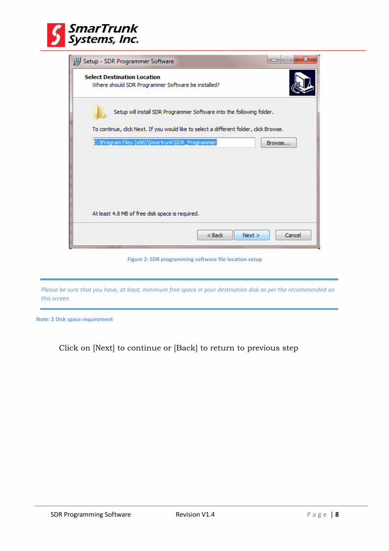
You will be prompted to introduce the destination folder. By default it is:
C:\Program Files (x86)\Smartrunk\SDR_Programmer
However, you can change it as per your convenience.
SDR Programming Software Revision V1.4 P a g e | 8
Figure 2: SDR programming software file location setup
Click on [Next] to continue or [Back] to return to previous step
Please be sure that you have, at least, minimum free space in your destination disk as per the recommended on
this screen
Note: 2 Disk space requirement
SDR Programming Software Revision V1.4 P a g e | 9
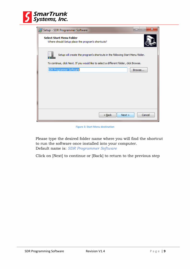
Figure 3: Start Menu destination
Please type the desired folder name where you will find the shortcut
to run the software once installed into your computer.
Default name is: SDR Programmer Software
Click on [Next] to continue or [Back] to return to the previous step
SDR Programming Software Revision V1.4 P a g e | 10
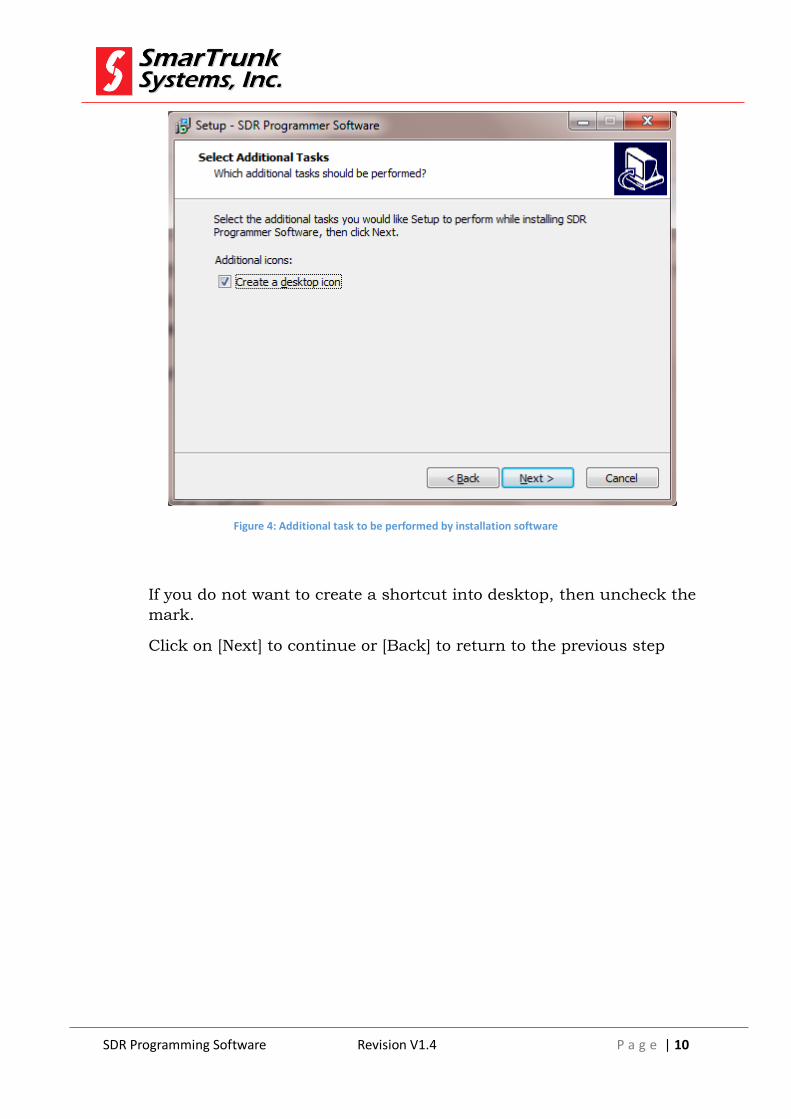
Figure 4: Additional task to be performed by installation software
If you do not want to create a shortcut into desktop, then uncheck the
mark.
Click on [Next] to continue or [Back] to return to the previous step

SDR Programming Software Revision V1.4 P a g e | 11
Figure 5: Installation parameters review
Check the option listed to ensure it is in agree to your desired settings,
then press [Install] to proceed with the installation or press [Back] to
return to the previous step.
As soon as you press install, the progress bar shows you the
installation process evolution. It will take only few seconds to perform.
As soon as the installation finishes, you will be asked to run the
software or to finish the process.
SDR Programming Software Revision V1.4 P a g e | 12
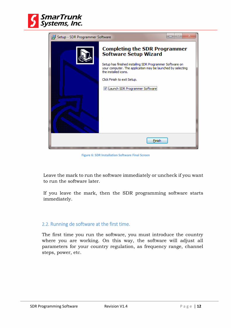
Figure 6: SDR Installation Software Final Screen
Leave the mark to run the software immediately or uncheck if you want
to run the software later.
If you leave the mark, then the SDR programming software starts
immediately.
2.2. Running de software at the first time.
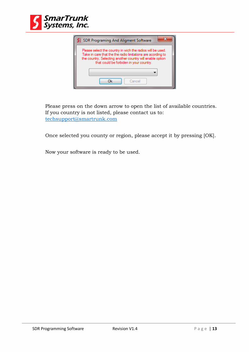
The first time you run the software, you must introduce the country
where you are working. On this way, the software will adjust all
parameters for your country regulation, as frequency range, channel
steps, power, etc.
SDR Programming Software Revision V1.4 P a g e | 13
Please press on the down arrow to open the list of available countries.
If you country is not listed, please contact us to:
Once selected you county or region, please accept it by pressing [OK].
Now your software is ready to be used.
SDR Programming Software Revision V1.4 P a g e | 14
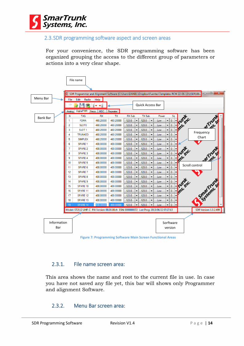
2.3. SDR programming software aspect and screen areas
For your convenience, the SDR programming software has been
organized grouping the access to the different group of parameters or
actions into a very clear shape.
2.3.1. File name screen area:
This area shows the name and root to the current file in use. In case
you have not saved any file yet, this bar will shows only Programmer
and alignment Software.
2.3.2. Menu Bar screen area:
File name
Bank Bar
Menu Bar
Quick Access Bar
Scroll control
Frequency
Chart
Information
Bar Sorftware
version
Figure 7: Programming Software Main Screen Functional Areas
SDR Programming Software Revision V1.4 P a g e | 15
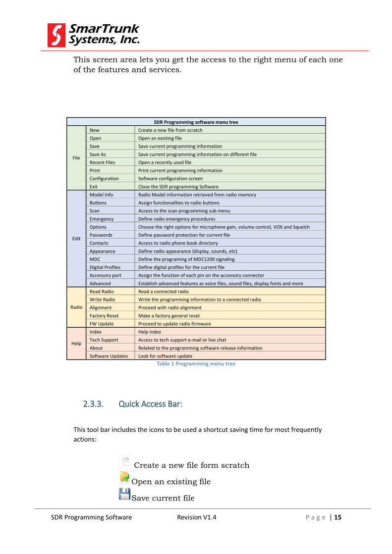
This screen area lets you get the access to the right menu of each one
of the features and services.
SDR Programming software menu tree
File
New Create a new file from scratch
Open Open an existing file
Save Save current programming information
Save As Save current programming information on different file
Recent Files Open a recently used file
Print Print current programming information
Configuration Software configuration screen
Exit Close the SDR programming Software
Edit
Model Info Radio Model information retrieved from radio memory
Buttons Assign functionalities to radio buttons
Scan Access to the scan programming sub menu
Emergency Define radio emergency procedures
Options Choose the right options for microphone gain, volume control, VOX and Squelch
Passwords Define password protection for current file
Contacts Access to radio phone book directory
Appearance Define radio appearance (display, sounds, etc)
MDC Define the programing of MDC1200 signaling
Digital Profiles Define digital profiles for the current file
Accessory port Assign the function of each pin on the accessory connector
Advanced Establish advanced features as voice files, sound files, display fonts and more
Radio
Read Radio Read a connected radio
Write Radio Write the programming information to a connected radio
Alignment Proceed with radio alignment
Factory Reset Make a factory general reset
FW Update Proceed to update radio firmware
Help
Index Help index
Tech Support Access to tech support e-mail or live chat
About Related to the programming software release information
Software Updates Look for software update
Table 1 Programming menu tree
2.3.3. Quick Access Bar:
This tool bar includes the icons to be used a shortcut saving time for most frequently
actions:
Create a new file form scratch
Open an existing file
Save current file
SDR Programming Software Revision V1.4 P a g e | 16
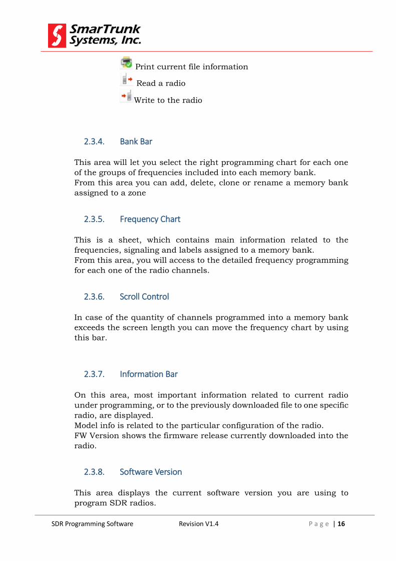
Print current file information
Read a radio
Write to the radio
2.3.4. Bank Bar
This area will let you select the right programming chart for each one
of the groups of frequencies included into each memory bank.
From this area you can add, delete, clone or rename a memory bank
assigned to a zone
2.3.5. Frequency Chart
This is a sheet, which contains main information related to the
frequencies, signaling and labels assigned to a memory bank.
From this area, you will access to the detailed frequency programming
for each one of the radio channels.
2.3.6. Scroll Control
In case of the quantity of channels programmed into a memory bank
exceeds the screen length you can move the frequency chart by using
this bar.
2.3.7. Information Bar
On this area, most important information related to current radio
under programming, or to the previously downloaded file to one specific
radio, are displayed.
Model info is related to the particular configuration of the radio.
FW Version shows the firmware release currently downloaded into the
radio.
2.3.8. Software Version
This area displays the current software version you are using to
program SDR radios.
SDR Programming Software Revision V1.4 P a g e | 17
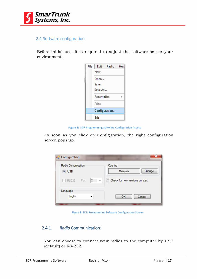
2.4. Software configuration
Before initial use, it is required to adjust the software as per your
environment.
Figure 8: SDR Programming Software Configuration Access
As soon as you click on Configuration, the right configuration
screen pops up.
Figure 9: SDR Programming Software Configuration Screen
2.4.1. Radio Communication:
You can choose to connect your radios to the computer by USB
(default) or RS-232.

SDR Programming Software Revision V1.4 P a g e | 18
In case you select RS-232, you must also indicate the port number
your hardware will provide to access to the radio. Serial data speed
and data mode is adjusted automatically by SDR software.
In case of USB media connection to the radio, it should be required
to install the drivers for your USB device.
As soon as you plug an SDR radio to the computer through the
USB port, you will be prompted to install the driver. Installation
software already copy the files into the selected directory you have
introduced into the installation time, under {Drivers} folder: For
example:
C:\Program Files(x86)\SmarTrunk\SDR_Programmer\Driver
Even when Serial RS-232 media can be used, most of actual
computers does not support real serial port, so we recommend the
USB media connection to the radio. Out or the compatibility with
existing hardware, USB media runs at 480Kbps which is many
times faster than RS-232.
2.4.2. Software Language:
You can choose the language for your software interface.
As SDR radio is not a standard device included into MS Windows standard library, you must install
the drivers before read or write a radio.
Note: 3 - Driver installation alert for USB Media Connection

SDR Programming Software Revision V1.4 P a g e | 19
Figure 10: Software Language Configuration Screen
Actually, only English, Spanish, Russian and Chinese are
available.
Select your desired language interface by click on the desired
option.
2.4.3. Automatic Software Update
New software updates shall include new features, revisions and
additional languages. It is very recommendable to keep the software
up to date.
Helping to keep your software up to date, the software can check
for new releases as soon as it starts.
Figure 11: Automatic Update Checkbox
Software update shall include new languages, so we recommend you try to keep your version
updated.
Note: 4 - Language Update Notice
SDR Programming Software Revision V1.4 P a g e | 20
In order to allow your software to check new versions as soon as it
starts, please check the mark (default).
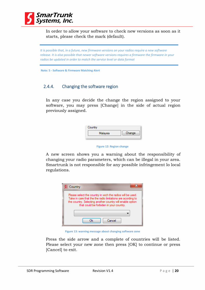
2.4.4. Changing the software region
In any case you decide the change the region assigned to your
software, you may press [Change] in the side of actual region
previously assigned.
Figure 12: Region change
A new screen shows you a warning about the responsibility of
changing your radio parameters, which can be illegal in your area.
Smartrunk is not responsible for any possible infringement lo local
regulations.
Figure 13: warning message about changing software zone
Press the side arrow and a complete of countries will be listed.
Please select your new zone then press [OK] to continue or press
[Cancel] to exit.
It is possible that, in a future, new firmware versions on your radios require a new software
release. It is also possible that newer software versions requires a firmware the firmware in your
radios be updated in order to match the service level or data format
Note: 5 - Software & Firmware Matching Alert
SDR Programming Software Revision V1.4 P a g e | 21
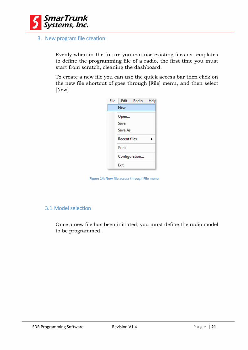
3. New program file creation:
Evenly when in the future you can use existing files as templates
to define the programming file of a radio, the first time you must
start from scratch, cleaning the dashboard.
To create a new file you can use the quick access bar then click on
the new file shortcut of goes through [File] menu, and then select
[New]
Figure 14: New file access through File menu
3.1. Model selection
Once a new file has been initiated, you must define the radio model
to be programmed.

SDR Programming Software Revision V1.4 P a g e | 22
Figure 15: Model information access through Edit Menu
SDR software can program any of the SmarTrunk Digital radios,
but each radio requires a proper definition for most of the
programming parameters.
One you get access to the Model Info menu, a new screen will pop
up:
Figure 16: Model Info Screen

SDR Programming Software Revision V1.4 P a g e | 23
To select your desired model, click on the right corner of the model
field then a scrollable list will drop down.
To select you model you must press cover the right name
corresponding to your model.
If your radio model is not in your list, please update your software.
If you are not sure about your model info, you can read the radio
by pressing on the quick access bar once your radio is connected
through the serial or USB cable with the computer where the SDR
programming software is running.
Model info is also into the serial number label inside of the radio,
removing the battery or in the bottom side of the mobile radios.
Once the model is selected, the correct frequency range, max power
and accessories are enabled into the model info screen.
Model: is the general model of the radio family
Internal Code: is a production code assigned to the radio into the
manufacturing process
Radio Type: is the type of radio (Mobile or portable)
Min Freq: Refer to the lower operational frequency that can be
programmed into your radio.
Max Freq: Refer to the lower operational frequency that can be
programmed into your radio.
Maximum Power: Is the maximum power supported by your RF
TX configuration. It may be different, depending on the region.
Keypad: will be active if your radio supports Keypad remote
(mobile) or built in (portable).
Bluetooth: Will be active if your radio is Bluetooth compatible.
GPS: Will be active if your radio has a built-in GPS or external GPS
is allowed (mobile).
Display: Will be active if your radio has display.
Accelerometer: Will be active if your radio has a built in G-sensor.
It is important to keep your software updated so ensure any SDR radio is into the model info list. If your
model is not into the current list, please update your radio
Note: 6 - Incomplete model info list requires software update

SDR Programming Software Revision V1.4 P a g e | 24
Once selected the right model press [OK] to accept it.
3.2. Radio Buttons Definition
Before using the radio, you must assign the functionality of each
one of the radio buttons.
Please click on [Edit] then [Buttons] to access to the buttons
definition screen.
Figure 17: Accessing to Radio Buttons screen
As soon as you click on Buttons, a new screen will displayed. The screen
and the functionality to be assigned to any buttons depends on the type
of radio and some of the features may be on shadows if your model does
not support it.
SDR Programming Software Revision V1.4 P a g e | 25
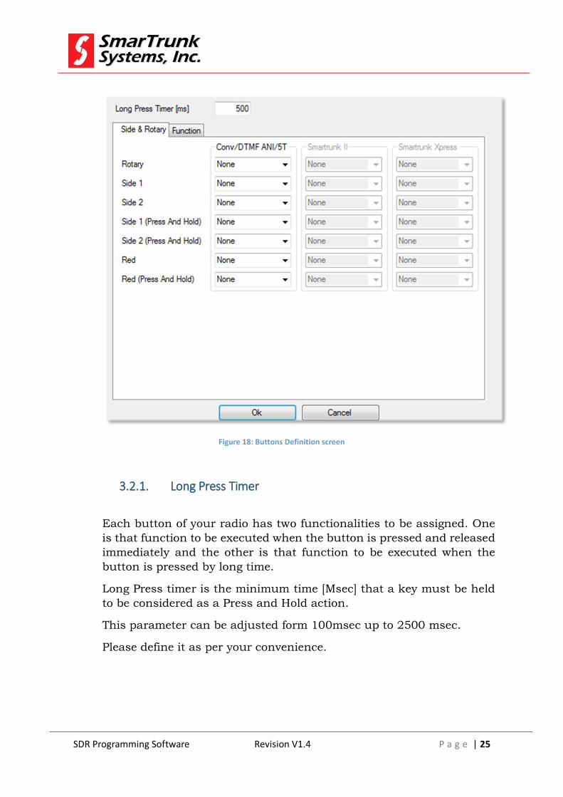
Figure 18: Buttons Definition screen
3.2.1. Long Press Timer
Each button of your radio has two functionalities to be assigned. One
is that function to be executed when the button is pressed and released
immediately and the other is that function to be executed when the
button is pressed by long time.
Long Press timer is the minimum time [Msec] that a key must be held
to be considered as a Press and Hold action.
This parameter can be adjusted form 100msec up to 2500 msec.
Please define it as per your convenience.

SDR Programming Software Revision V1.4 P a g e | 26
3.2.2. Buttons Actions:
The first folder on the Buttons Definition Screen lets you to assign
different functions to side buttons, emergency (top red push button)
or front buttons on mobile radios.
The second folder lets you select the additional function keys of your
radio. It may vary depending on the type of radio.
You must select the right folder to access to the right button list.
Click on the arrow to open the selection list of possible functions to
be assigned to any of the buttons, and then click on the desired
function to be assigned.
To finish the function assignment, press [Ok] to return to the main
dashboard.
Press And Hold means a long push function assigned to such button.
In the right area of the screen, the software shows the location of the
selected button on the type of radio to help you of the most
convenient function selection for that button.
Depending on the application firmware loaded into your radio core,
some functions may not be allowed to be selected or defined.
Depending on the kind of button, some functionalities are not
allowed.
The actions to be assigned to the buttons are:
3.2.2.1. Direct [Bank] Selection:
This function can only be assigned to the rotary encoder on
portable radios. Use this action to be assigned when you want to
use the rotary encoder to select a specific memory bank.
As the quantity of memory banks should be limited to the
maximum numbers of position of the encoder, in case you need
to address more banks than the number of slots, please use
[Bank Up] or [Bank Down] command.
SDR Programming Software Revision V1.4 P a g e | 27
3.2.2.2. Direct [Channel] Selection:
This function can only be assigned to the rotary encoder on
portable radios. Use this action to be assigned when you want to
use the rotary encoder to select a specific channel on the current
memory bank.
As the quantity of channels to be addressed should be limited to
the maximum numbers of position of the encoder, in case you
need to address more channels than the number of slots, please
use [Channel Up] or [Channel Down] command.
3.2.2.3. Bank up:
Assign this command to move one-step up on the memory bank
list. One bank up means select the next bank on the next folder
to the right into the folder list on the main SDR programming
software dashboard.
If the current memory bank selected is the last one on the right,
then you will jump to the first memory bank on the list.
In case only one Bank is programmed, this action takes no effect.
3.2.2.4. Bank Down:
In case your Bank selection points to un-programmed bank, the radio will alert with an alarm
tone and in case your radio has a display, the message UN-PROGRAMMED will be displayed
In case your Bank selection points to un-programmed bank, the radio will alert with an alarm
tone and in case your radio has a display, the message UN-PROGRAMMED will be displayed
Note: 7 – Un-programmed Bank message alert
Note: 8 – Un-programmed Bank message alert

SDR Programming Software Revision V1.4 P a g e | 28
Assign this command to move one-step down on the memory
bank list. One bank down means select the next bank on the next
folder to the left into the folder list on the main SDR programming
software dashboard.
If the current memory bank selected is the first one on the left,
then you will jump to the last memory bank on the list. (very right
side of the bank folders list)
In case only one Bank is programmed, this action takes no effect.
3.2.2.5. Channel Up
Assign this command to move one-step up on the list of channels
on the current memory bank. One Channel up means select the
next channel on the list of channels defined for the current
memory bank on the main SDR programming software
dashboard.
If the current selected channel selected is the last one on the list
of channels for the current list of channels for the current
memory bank, then it will jump to the first channel on the list
when this action is executed.
In case only one channel is programmed on the current memory
bank, this action takes no effect.
3.2.2.6. Channel Down:
Assign this command to move one-step up on the list of channels
on the current memory bank. One Channel down means select
the previous channel on the list of channels defined for the
current memory bank on the main SDR programming software
dashboard.
If the current selected channel selected is the first one on the list
of channels, for the current list of channels, on current memory
bank, then it will jump to the last channel on the list when this
action is executed.
In case only one channel is programmed on the current memory
bank, this action takes no effect.

SDR Programming Software Revision V1.4 P a g e | 29
3.2.2.7. Power Up:
Assign this command to change the RF output power selection.
This command will jump from Low Power to Mid Power, from Mid
Power to High Power, from High Power to Automatic Power or
from the Automatic Power to Low Power, depending on the
current power selection.
The absolute power assigned to each power selection must be
aligned as per Alignment section.
3.2.2.8. Power Down
Assign this command to scroll the RF output power selection.
This command will jump from High Power to Mid Power, from Mid
Power to Low Power, from Low Power to Automatic Power or from
the Automatic Power to High Power, depending on the current
power selection.
The absolute power assigned to each power selection must be
aligned as per Alignment section.
3.2.2.9. Monitor
Assign this command to open the audio path without any
signaling or carrier level consideration.
This command only operates on analog and hybrid mode.
3.2.2.10. Monitor Momentary
Assign this function when you want to open the audio path
without any signaling or carrier level consideration meantime the
assigned button is held.
As this function does not cares about any signaling, if you assign it to some radio into a fleet
you may know that the system privacy may be affected
Note: 9 - Monitor privacy warning for a fleet
SDR Programming Software Revision V1.4 P a g e | 30
This command only operates on analog and hybrid mode.
3.2.2.11. Signaling Override
Assign this command to open the audio path if exist a carrier with
higher level than the expected on the squelch level threshold.
This command only operates on analog and hybrid mode
3.2.2.12. Signal Override Momentary
Assign this command to open the audio path if exist a carrier with
higher level than the expected on the squelch level threshold
meantime the assigned button is held.
This command only operates on analog and hybrid mode.
3.2.2.13. Squelch Up:
Assign this command to increase one-step on the threshold level
to trigger the squelch.
If you reach the top of the values, this action will take no action.
It can’t be assigned to an instant action button. Only can be used as long press action
Note: 10 - Monitor Momentary allowed only to long press actions
As this function does not cares about any signaling, if you assign it to some radio into a fleet
you may know that the system privacy may be affected
Note: 11 – Signaling Override privacy warning for a fleet
It can’t be assigned to an instant action button. Only can be used as long press action
Note: 12 – Signaling Override Momentary allowed only to long press actions

SDR Programming Software Revision V1.4 P a g e | 31
The setting of this parameter modifies to the general radio
squelch level. Please note that any channel has a squelch offset
which adjust the noise floor for each frequency depending on the
environment.
Each step increase the threshold level in +2dB. This general
squelch control can run from -134dBm up to 0dBm.
3.2.2.14. Squelch Down
Assign this command to decrease one-step on the threshold level
to trigger the squelch.
Each step decrease the threshold level in -2dB. This general
squelch control can run from 0dBm down to -134dBm.
If you reach the bottom of the values, this action will take no
action.
The setting of this parameter modifies the general radio squelch
threshold level. Please note that any channel has a squelch offset
which adjust the noise floor for each frequency depending on the
environment.
3.2.2.15. Battery Status
Assign this command to ask for battery status.
This command only make sense only on portable radios.
When activated, this command will ask to the radio for display
report and voice report (if active).
In case the radio is on normal operation, it will show the real
current charge status in percentage, and the expected time to
finish (TTF) the remaining charge as per the average estimation
based on the last minute of power demand.
In case the radio is being recharged through USB port, it will
show the estimated time to complete the recharging process (TTF)
based on the last minute average of power demand.
The time estimation may be not accurate, especially because the
recharge process depends on the cell temperature and the duty
cycle on idle, Rx and TX status.

SDR Programming Software Revision V1.4 P a g e | 32
In case the radio is on the charger, this report is not supported.
3.2.2.16. RSSI (Received Signal Strength Indication)
Assign this action to request for a Received signal on the current
channel.
When executed, this command will play back the signal level in
case of analog or hybrid mode, and the level of accuracy on the
received data in case of digital mode (RDSI)
If your radio has a built-in display, it also will show the
information on the display temporary. If you want to know RSSI
or RDSI continuously, you can navigate the radio menu anytime
to set continuous RSSI measurement.
RSSI is also continuously displayed on radio display (if available)
as bars beyond the antenna symbol.
3.2.2.17. Toggle GPS
Assign this command to toggle GPS (on/off) in case your radio is
a portable one with built-in GPS sensor.
If enabled, your radio will announce actual GPS status after
executed the command. In case your radio has a built-in display,
you can also see the Satellite Dish Icon when the GPS sensor is
powered on.
3.2.2.18. GPS ON
Assign this command to turn On the GPS in case your radio is a
portable one with built-in GPS sensor
If enabled, your radio will announce actual GPS status after
executed the command. In case your radio has a built-in display,
On digital mode, an acceptable level of RDSI to recover the audio from the received data is over
80% of data accuracy (less than 20% BER). In case of analog signals, it may vary in function of
the noise floor for the channel, but commonly, signals better than -118dBm are acceptable
Note: 13 -RSSI and RDSI consideration for acceptable audio quality
SDR Programming Software Revision V1.4 P a g e | 33
you can also see the Satellite Dish Icon to prove the GPS sensor
has been powered on.
3.2.2.19. GPS Off
Assign this command to turn Off the GPS in case your radio is a
portable one with built-in GPS sensor
If enabled, your radio will announce actual GPS status after
executed the command. In case your radio has a built-in display,
you can also see the Satellite Dish in no longer in the display after
executed this command
3.2.2.20. Menu
Assign this command to let the user the access to the general
radio menu.
3.2.2.21. Scan
Assign this command to start the scan mode. Once pressed, the
radio will scan as per the program assigned to the scan mode.
3.2.2.22. Scan Group Up
Assign this command to increase the group of channels to be
scanned as per the program assigned to the scan mode.
If you reach the top group, you will start over from the bottom
one. If no scan groups were programmed, then this command
takes no action.
On Once the main menu is accessed, navigation control keys function are overridden getting
the default navigation functions Home, Back, OK and Menu Exit
Note: 14 - Alternative navigation keys function under menu mode alert
SDR Programming Software Revision V1.4 P a g e | 34
3.2.2.23. Scan Group Down
Assign this command to decrease the group of channels to be
scanned as per the program assigned to the scan mode.
If you reach the bottom group, you will start over from the top
one. If no scan groups were programmed, then this command
takes no action.
3.2.2.24. Default PTT ID
Assign this command to point to the default PTT ID assigned for
the radio as per the corresponding signaling program.
This feature is only valid in the channels with Selective calls
(Digital, MDC1200).
The default PTT ID depends on the signaling type programmed in
the channel. On MDC signaling, the default is an All Call ID,
meantime on any Digital mode the default ID can be assigned to
each radio as a specific ID.
3.2.2.25. Goto Phone Book
Assign this command if you want to create a shortcut to open the
phone book on the radio display. This function simplifies the call
setup on digital or MDC modes to access to a private of selective
call from the phone book directory.
3.2.2.26. Clear Hybrid
Hybrid mode is activated automatically as soon an analog carrier
with a positive signaling is received on digital mode.
Once the Hybrid mode is active, PTT transmits analog signals to
reply to the analog party.
Hybrid mode is held during 20 seconds after the last analog
carrier with positive signaling has been detected then it resumes
automatically going back to digital mode.
SDR Programming Software Revision V1.4 P a g e | 35
Hybrid mode is resumed also if a digital transmission is detected.
However, in case you wish to terminate the hybrid mode
immediately, you can assign this command to any key.
If so, when executed, it resumes the hybrid mode, then any
posterior PTT will be done on digital mode.
3.2.2.27. Set Hybrid
If an analog call must be initiated from a digital radio, then it
must be enforced to hybrid mode.
Assign this command to enforce the radio to hybrid mode.
3.2.2.28. Toggle Hybrid
Assign this command to use a single push button to jump from
digital to hybrid mode and vice versa.
3.2.2.29. Emergency
Assign this command to initiate the emergency mode.
Emergency routines may vary from different applications of your
networks and emergency console software.
Please refer to the emergency function for your current software
running on the Emergency/dispatch station.
3.3. Scan mode programming
To define the parameters of the scan mode operation, you must
select [Edit] then [Scan] on the Menu bar.
On emergency mode, the radio behavior is controlled remotely from the emergency control
software running into an emergency/dispatch console
Note: 15 - Emergency remote control

SDR Programming Software Revision V1.4 P a g e | 36
Figure 19: Accessing to the scan menu
Once you click on Scan, the scan screen is opened.
Figure 20: Scan groups programming screen
Scan group windows shows the information related to the scan
group and it lets you add, delete or modify the scan mode assigned
to different scan groups.
SDR Programming Software Revision V1.4 P a g e | 37
3.3.1. Adding a new Scan Group:
To add a new scan group, please focus the mouse pointer into the
scan group area then press the [Insert] key into your computer
keyboard. A new group with the name {Scan} will be added to your
scan group list
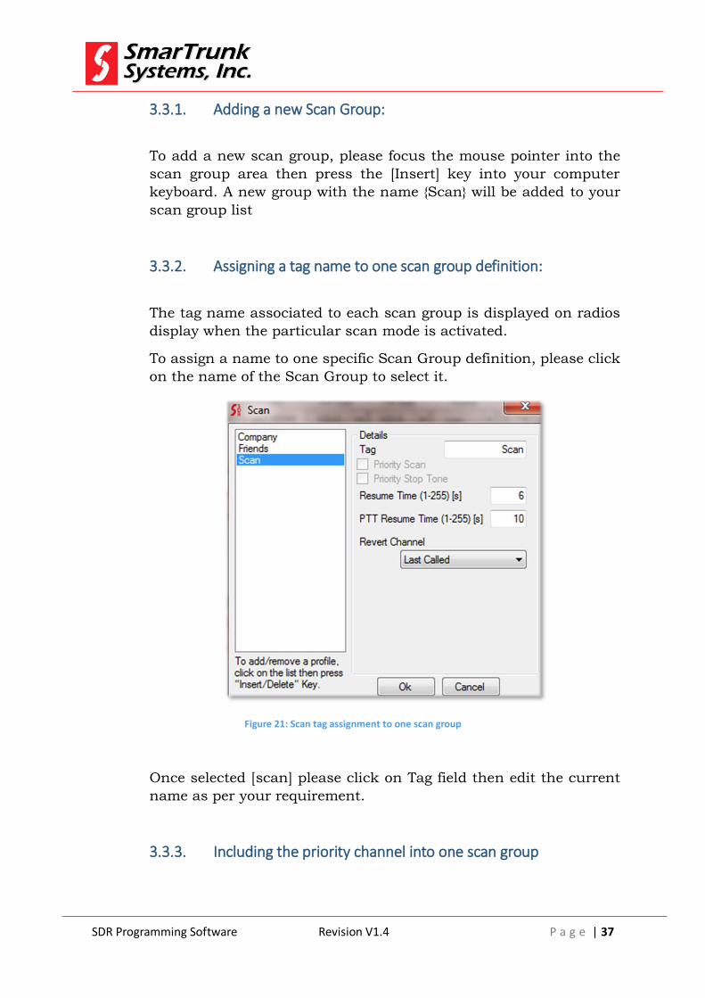
3.3.2. Assigning a tag name to one scan group definition:
The tag name associated to each scan group is displayed on radios
display when the particular scan mode is activated.
To assign a name to one specific Scan Group definition, please click
on the name of the Scan Group to select it.
Figure 21: Scan tag assignment to one scan group
Once selected [scan] please click on Tag field then edit the current
name as per your requirement.
3.3.3. Including the priority channel into one scan group
SDR Programming Software Revision V1.4 P a g e | 38
Running into scan mode, the radio will follow the scanning
frequencies as per scan group definition, but it should be required
to include a channel to be included into the current list, with higher
recurrence than any other channel in the list. If so, a priority
channel will be scanned once per each channel scanned, getting the
top priority.
The channel priority must be assigned into the channel definition
option screen.
To include the priority channel to the selected scan group, please
check the priority check-box.
3.3.4. Adding priority busy alert tone
If you need the radio generates an alert tone when the scan process
detects activity on the priority channel, then please check the
Priority Stop Tone.
3.3.5. Assigning the Resume time to a Scan Group
If a positive signal is detected, the scan process stops temporary,
waiting for any user action, which finishes the scan mode. If the user
does not take any action and the positive signal remains on the
channel, then the scan resumes after certain time.
Resume time controls the time to stays in a busy channel before
resumes the scan mode.
It support from 1 to 255 seconds. Default time is 6 seconds
3.3.6. Assigning a PTT resume time to a scan group
If the scan mode stops due to some positive signal and the user keys
the PTT, then the scan process will be automatically resumed after
certain delay.
PTT resumes time is the time to stay into the current channel after
the PTT has been released.
It support from 1 to 255 seconds. Default time is 10 seconds

SDR Programming Software Revision V1.4 P a g e | 39
3.3.7. Reverting a transmission into a specific channel on scan mode
You can specify the channel to be used to transmit, out of the
scanning process. It means, which should be the channel to revert
any transmission once the scan process has detected a positive
carrier.
By default, after the scan mode is activated, or after a power on cycle,
the radio will transmit into the first channel on the list.
To select the right revert mode, please click on Revert Channel arrow
then a drop list will be displayed.
Revert on the [last called] to transmit in the last channel where the
scan has stopped.
Choose [Selected] to revert on the channel selected by the user,
could be a channel that do not belong to the selected Scan Group.
Choose [Selected + Talk Around] to revert into the channel where
the scan has detected a positive signal, but in case the scanner has
not detected it, then the transmission will be directed to the user-
selected channel.
Choose [Priority] to revert into the priority channel. If there is not
priority channel, then it will revert on the last channel where a
positive signal has been detected.
Choose [Priority + Talk Around] to revert into the channel where
the scan has detected a positive signal, but in case the scanner has
not detected it, then the transmission will be directed to the priority
channel. If there is not priority channel, then it will revert on the last
channel where a positive signal has been detected.
3.3.8. Deleting a Scan Group.
To delete a scan group, please click on the group name then press
[Delete] on your computer keyboard. Only the last scan group can
be deleted if not in use into any profile.
3.3.9. Exit from Scan Group programming mode

SDR Programming Software Revision V1.4 P a g e | 40
Once finished the programming of the different scan groups and its
parameters, press [OK] to store the changes going back to the main
dashboard
3.4. Setting the emergency mode:
Emergency mode is triggered from an emergency command. Commonly
it is a long push on the red top button for portable radios or any
programmed function on mobile radio, but you can choose the most
convenient way to set the radio in emergency mode as per 3.4.
To access to the Emergency mode programming feature, please click on
[Menu] then in [Emergency] on the Menu bar area.
Figure 22: Access to the Emergency Programming menu through Menu bar
As soon as you click there, the Emergency programming screen comes
up.

SDR Programming Software Revision V1.4 P a g e | 41
Figure 23: Emergency programming screen
To finish the Emergency mode programming, press [Ok] or press
[Cancel] to exit.
3.4.1. Emergency Silent Mode:
Once the Emergency mode is launched due to any user action (press
the button assigned as emergency button) or due to any automate
procedure (GPS Geo Fence infringement, Man running detection or
man down detection), the radio will jump to Emergency mode. On
this mode, the radio reports an alarm via RF sending the GPS
location (if available), user ID, and alarm condition status, but it also
can generate a local alarm tone in the radio through the speaker to
alert this situation locally.
Check Silent Mode Box in order to do not generate any
sound through radio speaker to alert about the emergency mode
locally.
3.4.2. Emergency mode local deactivation:
Once the radio is set in the emergency mode, there are two ways to
terminate it: The first one is by pushing the emergency button again
and the second one is from the remote emergency monitoring
software, which can remotely deactivate the emergency mode over
the air.
If you want to allow local termination of the emergency model by
pressing the emergency button, then check the box
Remote deactivation is allowed anytime.

SDR Programming Software Revision V1.4 P a g e | 42
3.4.3. Emergency report period
Once in emergency mode, the radio will report the situation over the
air, repeating the process periodically.
To set the period for such action, please fill the field
Minimum possible value is 1 second and maximum is 255 seconds.
3.5. Enhanced optional programing
On this step, you can configure microphone gain, minimum audio
volume, main squelch level, clone mode, VOX sensibility and power on
mode.
To reach the optional programming, please go to the Menu index then
click on [Menu] then [Options]. Immediately the options screen will pops
up.
Figure 24: Option screen access through Menu bar
As soon as you click on Options, the Optional programming features
screen will pops up.

SDR Programming Software Revision V1.4 P a g e | 43
Figure 25: Options Program screen
To save the setting press [Ok] or [Cancel] to exit without saving the data
changes
3.5.1. Analog Mic gain settings
This area lest you set the most convenient mic gain for analog mode,
for internal or external microphone.
Figure 26: Analog mic gain screen
3.5.1.1. Analog AGC
Even when the mic gain can be adjusted manually, you can
override any gain setting and leaving the Automatic gain Control
to adjust the mic gain to ensure the most efficient modulation.
This feature is especially useful to use the radio in noisy
environments.

SDR Programming Software Revision V1.4 P a g e | 44
To enable this feature, please check the AGC box
The AGC will adjust the mic gain to guarantee maximum
deviation.
3.5.1.2. Analog Mic Gain:
If AGC is not in use, you can adjust the mic gain as per your
requirement. To select the right mic gain, please click on the
arrow of the Mic Gain tab. A drop down list will be expanded then
you can select the desired gain value.
Figure 27: Analog mic gain selection
3.5.1.3. External PTT mic gain:
In the event you plug an external microphone with PTT control,
the radio can adjust the gain for such input independently of the
internal mic gain.
Even when your gain selection should be too high, the radio has a built-in limiter to avoid over
deviation. Over certain values, the limiter may add some compression to the voice, adding some
distortion
Note: 16 - Over Gain limiter warning

SDR Programming Software Revision V1.4 P a g e | 45
To select the right External Mic gain, please click on the arrow of
the Ext PTT Mic Gain tab. A drop down list will be expanded then
you can select the desired gain value.
Figure 28: External PTT mic gain setup screen
3.5.2. Digital Mic gain settings
This area lets you set the most convenient mic gain for digital mode,
for internal or external microphone.
Figure 29: Digital mic gain screen
3.5.2.1. Digital AGC (automatic Gain Control)
Even when the mic gain can be adjusted manually, you can get a
better performance on noisy environments setting the Automatic
Gain Control to adjust the mic gain to ensure the most efficient
modulation.

SDR Programming Software Revision V1.4 P a g e | 46
Before to assign the automatic gain control, you must set the
target gain for the AGC, pressing on the right arrow of the Digital
Mic Gain drop list then click on the desired target.
Figure 30: Digital AGC target selection
To enable this feature, please check the AGC box
The AGC will adjust the mic gain to guarantee optimum audio
level.
3.5.2.2. Digital Mic Gain:
If AGC is not in use, you can adjust the mic gain as per your
requirement. To select the right mic gain, please click on the
arrow of the Mic Gain tab. A drop down list will be expanded then
you can select the desired gain value.
Figure 31: Digital mic gain selection
Wrong mic gain alignment on digital mode may create additional background noise and it will
result uncomfortable for other parties..
Note: 17 – Digital Over-Gain limiter warning
SDR Programming Software Revision V1.4 P a g e | 47
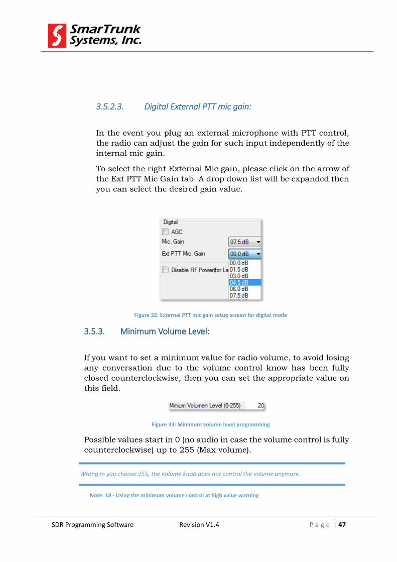
3.5.2.3. Digital External PTT mic gain:
In the event you plug an external microphone with PTT control,
the radio can adjust the gain for such input independently of the
internal mic gain.
To select the right External Mic gain, please click on the arrow of
the Ext PTT Mic Gain tab. A drop down list will be expanded then
you can select the desired gain value.
Figure 32: External PTT mic gain setup screen for digital mode
3.5.3. Minimum Volume Level:
If you want to set a minimum value for radio volume, to avoid losing
any conversation due to the volume control know has been fully
closed counterclockwise, then you can set the appropriate value on
this field.
Figure 33: Minimum volume level programming
Possible values start in 0 (no audio in case the volume control is fully
counterclockwise) up to 255 (Max volume).
Wrong In you choose 255, the volume knob does not control the volume anymore.
Note: 18 - Using the minimum volume control at high value warning

SDR Programming Software Revision V1.4 P a g e | 48
3.5.4. Private volume level
If the radio has G-sensor included, then it automatically detects the
radio position. The detected position is like expected for somebody
who moves the radio close to the ear, the radio understand that it
must jump to private mode.
Working on private mode, the audio volume is controlled by the value
that programmed on this field.
3.5.5. Squelch Level:
This is the main squelch level control for your radio. This level is the
main reference for the squelch threshold to open the speaker when
the detected carrier is over certain value.
When you assign any squelch control on radio buttons (see 3.2.2.13
and 3.2.2.14), the radio software adjust temporary this value. If a
power cycle happens, after boot, the radio loads again this value.
3.5.6. Clone setup
To simplify the radio programming, you can use a clone cable, which
allows you to send all programming data from a master radio to a
slave radio.
Figure 34: Clone screen settings
3.5.6.1. Clone Allow Source:

SDR Programming Software Revision V1.4 P a g e | 49
Check this box to enable this radio sending data as master radio.
3.5.6.2. Clone Allow Target:
Check this box to enable this radio to receive clone data from
other radio already defined as master (Source).
3.5.7. VOX control:
VOX lets the radio jump to TX mode when voice is detected on the
microphone input. This feature helps to use the radio as a hands
free device.
Sensibility of this feature is controlled by VOX control Threshold
level field
Set this parameter into a desired value. High values means high
sensibility and higher hold time. Lower values, implies lower
sensibility and shorter hold time.
3.5.8. Power Up mode:
In case you are programming a mobile device, ST-3118, the mode
that the radio starts when the DC power is connected, can be
adjusted from this control.
Figure 35: Power Up Mode control box
Press on the side arrow to open the list of options then press on the
desired one to load it.

SDR Programming Software Revision V1.4 P a g e | 50
Figure 36: Power on mode selection
3.5.8.1. Power on: Backup
Select this option if you want the mobile radio keep the same
status than it was at the time the DC power was interrupted.
That means that if the radio was powered off, then it will stay
powered off when the DC power be connected again, and in the
case the radio was powered on at the time the DC power was
disconnected, then it will become powered on automatically once
the DC power be reestablished.
3.5.8.2. Power on: On
Choose this option if you want the radio becomes powered on any
time DC power is reestablished.
3.5.8.3. Power On: Off
Choose this option if you want the radio remains powered off once
the DC Power becomes reestablished.
3.5.9. Disable RF Power:
For laboratory issues, sometimes it is important that the RF power
be deactivated to preserve the circuitry, specially the RF Power
Amplifier.
Check this box if you want to cancel the RF power amplifier but do
not forget to clear it before send the radio back to the user.
SDR Programming Software Revision V1.4 P a g e | 51
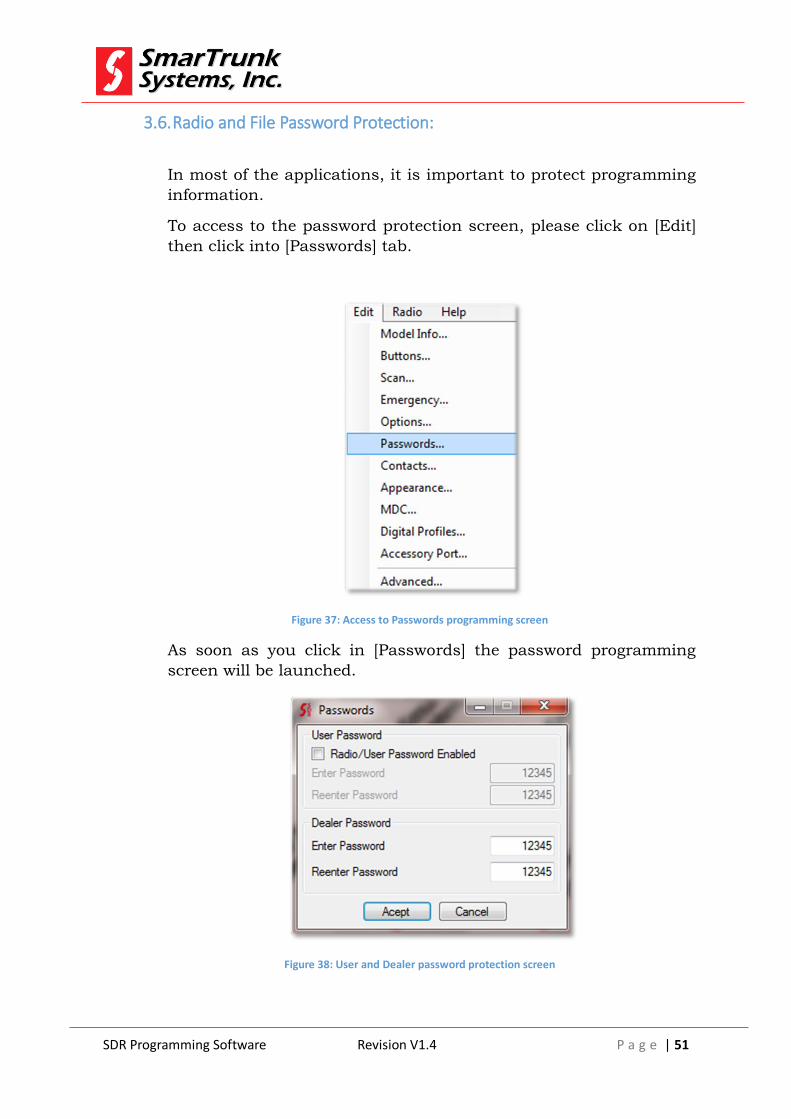
3.6. Radio and File Password Protection:
In most of the applications, it is important to protect programming
information.
To access to the password protection screen, please click on [Edit]
then click into [Passwords] tab.
Figure 37: Access to Passwords programming screen
As soon as you click in [Passwords] the password programming
screen will be launched.
Figure 38: User and Dealer password protection screen

SDR Programming Software Revision V1.4 P a g e | 52
3.6.1. User Password protection:
If you want to protect the radio itself, you can set Radio/User
Password Enabled checkbox. On this case, you must fill the
password and password confirmation fields with the code you expect
to be typed on radio keyboard to let the radio go to operational mode.
In case the password and the password confirmation do not match
each other, then the field will be highlighted in red, but it becomes
normal as soon as both keys are equal.
As soon as you turn on a radio password protected, you will be
prompted to type the password assigned on these fields. If the typed
password do not matches the right password, after the third try, it
will be locked and it must return to your dealer to be unlocked by a
new programming session.
3.6.2. Dealer Password protection.
The information you download to a radio, containing frequencies,
settings and other sensitive information is password protected.
Default password is 12345. If you use other password than default,
then you cannot read the radio with programming software.
Please be sure that you save the password information in a safe place
as backup.
If you want to change default password to any other key, please type
it into Dealer password field. In case the password and the password
confirmation do not match each other, then the field will be
highlighted in red, but it becomes normal as soon as both keys are
equal.
The password is assigned to the radio once you upload the
programming information to the radio.
That information is also saved into the file backup into your
computer if you save it, in such a case, you must enter the right
password to open the file on your computer.
3.7. Phone book edition
SDR Programming Software Revision V1.4 P a g e | 53
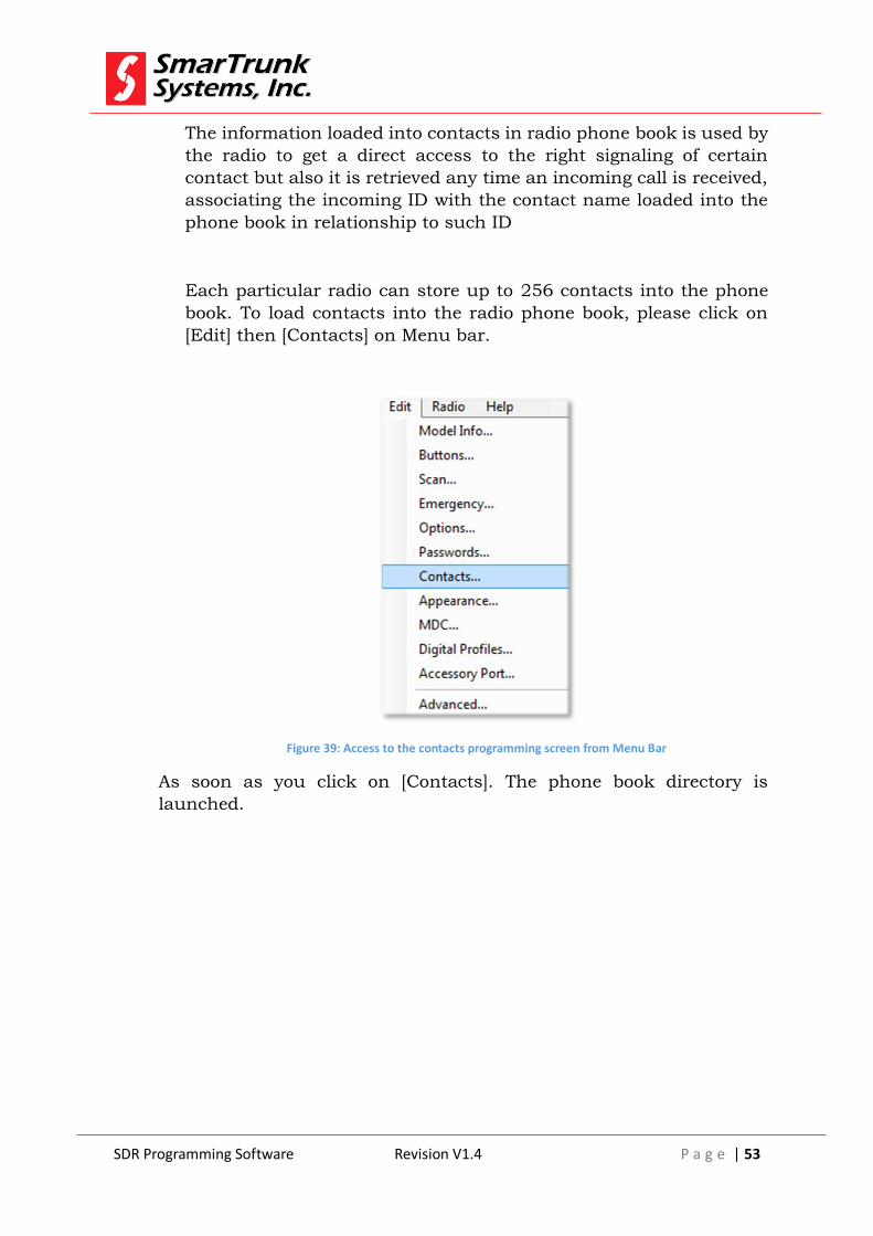
The information loaded into contacts in radio phone book is used by
the radio to get a direct access to the right signaling of certain
contact but also it is retrieved any time an incoming call is received,
associating the incoming ID with the contact name loaded into the
phone book in relationship to such ID
Each particular radio can store up to 256 contacts into the phone
book. To load contacts into the radio phone book, please click on
[Edit] then [Contacts] on Menu bar.
Figure 39: Access to the contacts programming screen from Menu Bar
As soon as you click on [Contacts]. The phone book directory is
launched.

SDR Programming Software Revision V1.4 P a g e | 54
Figure 40: Phone book screen
3.7.1. Adding a contact to the phone book
To add a new contact to the phone book, please click on the first
clear tag then type the tag name. You can use up to 16 characters
length for contact name.
After typed the new contact name, please assign the contact ID, by
typing the assigned ID to the user referred under such contact name.
Finally, assign the kind of signaling to be encoded or decoded to talk
with such user, by click on the arrow of Protocol column. You can
choose Digital or MDC1200 signaling.
Repeat these steps if you want to add more contacts then press [OK]
to store the changes or [Cancel] to discard it.
3.7.2. Deleting a contact from phone book list
SDR Programming Software Revision V1.4 P a g e | 55
To delete a contact from the phone book directory, click on the order
number (first column on the left side) to mark the contact the press
{Delete} into your computer keyboard to erase it.
Once you finish any desired changes, please press [OK] to store the
changes or [Cancel] to discard it.
3.7.3. Editing a contact on the phone book directory.
To change the information of any field on the current phone book
directory, please do click into the right field to change and introduce
any desired changes from your computer keyboard. If the field you
want to change is the signaling protocol, then click on the right
arrow to open the drop list, and then select the desired one.
Once you finish any desired changes, please press [OK] to store the
changes or [Cancel] to discard it.
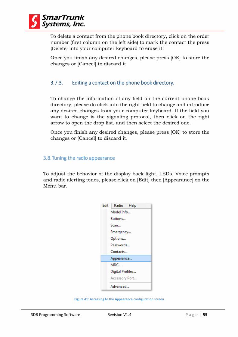
3.8. Tuning the radio appearance
To adjust the behavior of the display back light, LEDs, Voice prompts
and radio alerting tones, please click on [Edit] then [Appearance] on the
Menu bar.
Figure 41: Accessing to the Appearance configuration screen
SDR Programming Software Revision V1.4 P a g e | 56
As soon as you click on [Appearance] the Appearance screen will pops
up.
That screen contains three folders, which can be selected by doing click
on the folder name.
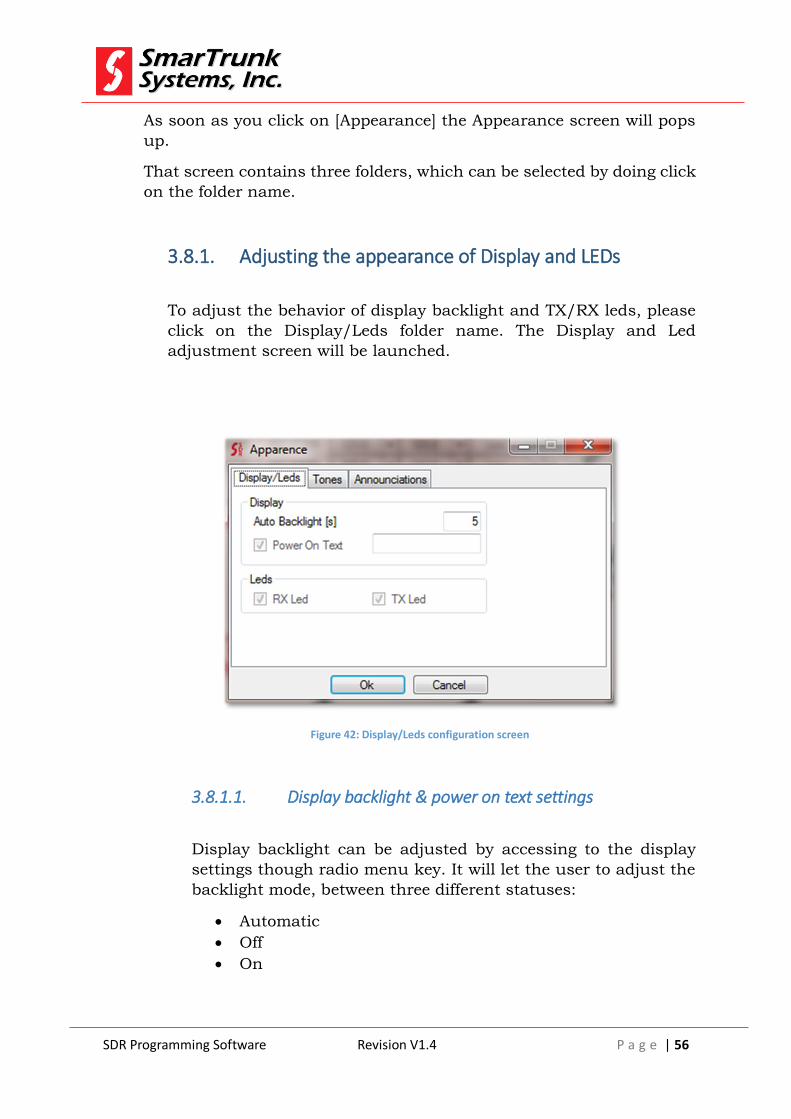
3.8.1. Adjusting the appearance of Display and LEDs
To adjust the behavior of display backlight and TX/RX leds, please
click on the Display/Leds folder name. The Display and Led
adjustment screen will be launched.
Figure 42: Display/Leds configuration screen
3.8.1.1. Display backlight & power on text settings
Display backlight can be adjusted by accessing to the display
settings though radio menu key. It will let the user to adjust the
backlight mode, between three different statuses:
Automatic
Off
On

SDR Programming Software Revision V1.4 P a g e | 57
In case Automatic mode is selected, the display and keyboard
backlight will remain on up to the quantity of seconds loaded into
Auto backlight field.
Figure 43: Auto backlight hold-on delay programming
To adjust such a time, please enter the quantity of seconds to
keep the backlight on after any key has been pressed or a new
positive signaling has been received. Valid values are between 1
sec. and 255 seconds.
This value can be adjusted also from radio menu, but it is a
temporary correction, which will be adjusted any time the radio
is turned on, using the value loaded into this field.
3.8.1.2. Enabling/disabling the power on text
Any time the radio is powered on, it can show a brief slide show
or just a simper power on text.
If the slide show is not loaded into radio memory, and you want
the radio shows a simple text when it starts, then check the Power
On Text Checkbox then type the right text into the field.
3.8.1.3. Adjusting the RX/TX Leds behavior
By some reason, some applications need no lights coming up
when a carrier is received of it is not required that the TX led
comes up when PTT is keyed.
To control such situations, please check/uncheck the right
control box of the Leds control area
Figure 44: Leds control area
SmarTrunk

SDR Programming Software Revision V1.4 P a g e | 58
3.8.2. Adjusting the Radio Tones
Some of the radio functions may generate an alert tone to the user.
To adjust it, please do click on the Tones tab on the Appearance
screen
Figure 45: Radio tones configuration screen
To store the selected values press [Ok], press into other tab or
press [Cancel] to exit without storing the changes.
3.8.2.1. Bells Tone level
In private incoming calls, a ring tone will be heard. Enter the right
volume for the ring tone into this field.
Ring tone volume can later be adjusted from radio menu. Values
must be set between 0 (no ring) and 255 (max value)
3.8.2.2. Scaling Tones Alerts
In some application, it is comfortable that the level of the ring
tones comes up gradually instead of make it a max level.
SDR Programming Software Revision V1.4 P a g e | 59
If you want gradually increasing ring tone volume, please check
this checkbox.
3.8.2.3. PTT keyed alerting tone control
If you want to activate an alert tone any time the PTT is keyed,
please check this checkbox. Otherwise, no sound should be
played back by radio when the PTT is keyed.
3.8.2.4. PTT de-keyed alerting tone control
If you want to activate an alert tone any time the PTT is de-keyed,
please check this checkbox. Otherwise, no sound should be
played back by radio when the PTT is de-keyed.
3.8.2.5. Key pulsed alerting tone
If you want to activate an alert tone any time any keyboard key is
pulsed, please check this checkbox. Otherwise, no sound should
be played back by radio when any keyboard key is pulsed.
3.8.2.6. TOT pre-expiration alerting tone control
Check this checkbox if you want the radio alert to the user 3
seconds before the Time Out Timer expires. If not checked, the
radio will never alert about timer expiration and the PTT will be
locked without any previous notice
3.8.2.7. Rotary switch moved alerting tone
SDR Programming Software Revision V1.4 P a g e | 60
If you want to activate an alert tone any time the rotary switch is
moved, please check this checkbox. Otherwise, no sound should
be played back by radio when the rotary switch is moved to a
different position.
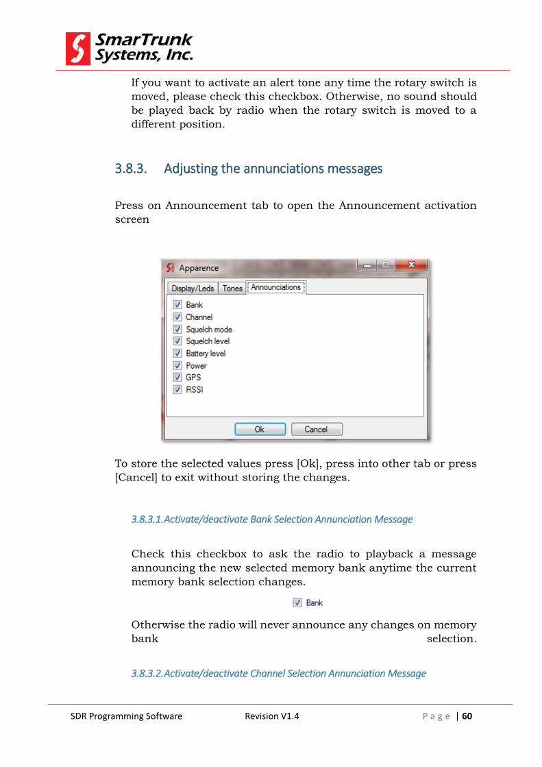
3.8.3. Adjusting the annunciations messages
Press on Announcement tab to open the Announcement activation
screen
To store the selected values press [Ok], press into other tab or press
[Cancel] to exit without storing the changes.
3.8.3.1. Activate/deactivate Bank Selection Annunciation Message
Check this checkbox to ask the radio to playback a message
announcing the new selected memory bank anytime the current
memory bank selection changes.
Otherwise the radio will never announce any changes on memory
bank selection.
3.8.3.2. Activate/deactivate Channel Selection Annunciation Message
SDR Programming Software Revision V1.4 P a g e | 61
Check this checkbox to ask the radio to playback a message
announcing the new selected channel any time the current
channel selection changes to other channel
Otherwise, the radio will never announce any changes on channel
selection.
3.8.3.3. Activate/deactivate Squelch Mode Selection Annunciation Message
Check this checkbox to ask the radio to playback a message
announcing the new status for radio squelch alternative
functionality. Possible messages are Squelch Monitor, Signaling
Override or Normal
Otherwise, the radio will never announce any change on squelch
operational mode.
3.8.3.4. Activate/deactivate Squelch level changes Annunciation Message
Check this checkbox to ask to the radio to announce the new
squelch level.
Otherwise, the radios will never announce any changes on
squelch level settings.
3.8.3.5. Activate/deactivate Battery Level Annunciation Message
Check this option to request a complete battery status report
announcement. This service will provide actual battery charge
and the remaining time to completely discharge the battery
considering the average of the last minute current demand.
In case the battery is being recharged from the USB port, this
message will report the remaining time to complete the
recharging process.
This function is only applicable to portable radios.
SDR Programming Software Revision V1.4 P a g e | 62
If unchecked, the radio will never announce current battery
status.
3.8.3.6. Activate/deactivate Power Level Annunciation Message
Check this mark to request an announcement any time the radio
RF power has been selected to other level than the current one.
Otherwise, the radio will never announce any change on RF
power level.
3.8.3.7. Activate/deactivate GPS status Annunciation Message
Check this box if you want the radio announce any changes into
the GPS status, for example, when it is powered on/off or when
the GPS is fixed or the signal has been lost.
Otherwise the radio will never playback any message when GPS
status changes
3.8.3.8. Activate/deactivate RSSI Level Annunciation Message
Check this box of you want that the radios announce the status
of RSS when requested by the user.
Otherwise, the report will be done only through display.
3.9. MDC signaling configuration
To define the analog MDC signaling, please click on [Edit] then [MDC]
on the Menu bar.

SDR Programming Software Revision V1.4 P a g e | 63
Figure 46: Accessing to the MDC signaling configuration screen
As soon as you click on [MDC] the MDC signaling definition screen will
pops up.
Figure 47: MDC Signaling control screen
After defined all the desired properties, press [Ok] to save, press
[Cancel] to exit or go to advanced mode by pressing [Advanced].

SDR Programming Software Revision V1.4 P a g e | 64
3.9.1. MDC signaling parameters:
MDC protocol is only for analog mode. It will be defined by many
parameters as descripted bellow.
3.9.1.1. TAG:
This is a label to be assigned to this particular signaling
configuration. You can type any name up to 16 characters on this
field.
3.9.1.2. [ID]
This is the Individual identification (ID) to be assigned to this
particular radio. This ID identifies the radio from any other radio
in a group. This field accept only numeric characters from 0 to 9
with 4 digit format.
In case PTT ID is required, this is the information that will be sent
over the air.
3.9.1.3. Selective Calls
Check this box if you want your radio only accept incoming calls
coming from other radios, which has the PPT ID active, only in
the event that the received ID matches any of the IDs defined on
this radio, as Individual or group ID
3.9.1.4. Group:

SDR Programming Software Revision V1.4 P a g e | 65
This particular radio may belong to certain group. Any time that
the group number filled on this tag, this radio will accept the
selective call.
To use this feature Selective Calls featured must be checked,
otherwise, this field will be in shadows.
3.9.1.5. Default PTT ID
If checked, this box enables the PTT ID field to load in the ID to
be sent over the air to initiate a selective call. This field length is
up to four digits (numeric only)
This function must be checked if you want to place a selective call
to any radio, which already has the selective call already enabled.
If this function is active, then PTT ANI features are disabled.
3.9.1.6. PTT ID
This couple of checkbox enable the over the air identification to
be sent any time the PTT is keyed or released. Both checkbox can
be set at the time. I so the radio will send both (PTT keyed and
released)
ANI should be displayed on the receivers but it does not allow
placing selective calls by itself.
3.9.2. Advanced MDC parameters configuration
To access to MDC advanced programming, please press [Advanced]
on MDC Signaling Screen
On this case, the screen will add a new section in the side where you
can adjust the advanced parameters.

SDR Programming Software Revision V1.4 P a g e | 66
Figure 48: Advanced MDC signaling screen
To save the changes on this screen, press [Ok]. To go back to Basic
mode press [Basic] or press [Cancel to Exit without saving the
changes.
3.9.2.1. TX Signaling with Sub Audio
Commonly, sub audible signaling as CTCSS or DCS must be
interrupted meantime the MDC signaling is generated. On this
way, the MDC signaling itself will be not audible on receivers.
However, in some cases, it is required to allow a possible repeater
to re-transmit the information for receivers.
In case you want to enable the sub audible signaling meantime
the MDC signaling is on the air, please check this box. Otherwise,
the signaling will be interrupted meantime MDC signaling is on
the air.
3.9.2.2. Pre Time:
The transmitter must wait few milliseconds before sending the
signaling after the RF power has reached the expected power to
guarantee the link. Most of the receivers needs, at least 50

SDR Programming Software Revision V1.4 P a g e | 67
milliseconds to ensure the reception once the carrier has been
sent over the air.
To avoid data lost due to this dead time, you can adjust the time
from the PTT asserted by the user up to the moment the signaling
start to be transmitted.
Please fill this field with the maximum expected delay to ensure
any radio into the system is ready to receive the MDC data frame.
Please consider to extend this time if you have a repeater in
middle, because the repeater itself adds additional delay.
In case there were radios with battery saver function active, you
must considerate it also adding additional pre time to ensures the
radio wakes up, detects the carriers and sets ready to decode
MDC information.
This value can be set from 1 millisecond up to 2550 milliseconds
3.9.2.3. Coast Time:
This represents the time the radio will consider to be merged into
a determinate call after the carrier got lost. In some cases, when
radios operates in the edge of the coverage area, this parameter
helps to keeps operating into the same call.
You must administrate this value to get a perfect balance between
unexpected exit of a call due to poor signal and the possibility to
be merged into other conversation different than the expected
one, in case the call changes meantime the radio comes back to
the coverage area.
This value can be set from 1 millisecond up to 2550 milliseconds.
3.9.2.4. Ack Pre Time

SDR Programming Software Revision V1.4 P a g e | 68
In some conditions, MDC protocol required the receiver
acknowledges the received information. In such a case, the radio
who receives the MDC data, must sets the radio in TX mode,
ensures the sender also changes from TX to RX and it radio is
ready to decode the ACK information.
This field controls the amount of milliseconds to wait before
sending an ACK frame to the sender.
This value can be set from 1 millisecond up to 2550 milliseconds.
3.9.3. Adding an MDC profile:
MDC must be defined by profiles, which later are assigned to the
different channels in the main dashboard.
To create a new profile, please click on any existing profile on the
MDC profile screen the press {Insert} into your computer keyboard
to add one more profile into the programming file.
Figure 49: MDC add/delete profile screen
Once created the new MDC profile, you can adjust any parameter as
explained before.
3.9.4. Deleting an existing MDC profile
Only the last profile in the list can be deleted due to the existing
relations between the list of profiles and the channels
programmed on the radio memory.
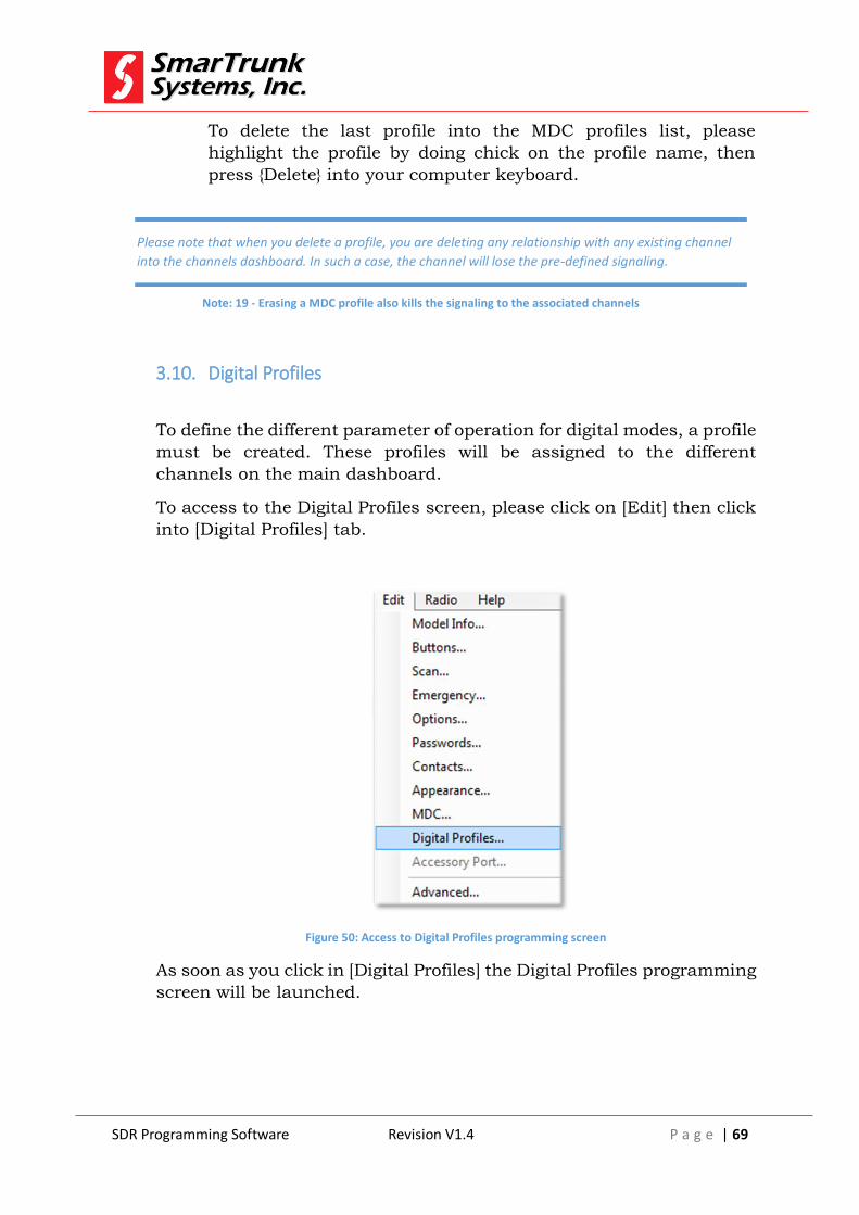
SDR Programming Software Revision V1.4 P a g e | 69
To delete the last profile into the MDC profiles list, please
highlight the profile by doing chick on the profile name, then
press {Delete} into your computer keyboard.
3.10. Digital Profiles
To define the different parameter of operation for digital modes, a profile
must be created. These profiles will be assigned to the different
channels on the main dashboard.
To access to the Digital Profiles screen, please click on [Edit] then click
into [Digital Profiles] tab.
Figure 50: Access to Digital Profiles programming screen
As soon as you click in [Digital Profiles] the Digital Profiles programming
screen will be launched.
Please note that when you delete a profile, you are deleting any relationship with any existing channel
into the channels dashboard. In such a case, the channel will lose the pre-defined signaling.
Note: 19 - Erasing a MDC profile also kills the signaling to the associated channels
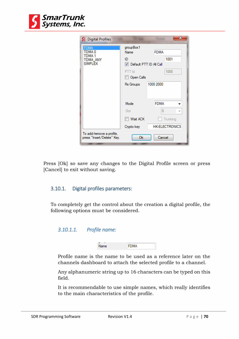
SDR Programming Software Revision V1.4 P a g e | 70
Press [Ok] so save any changes to the Digital Profile screen or press
[Cancel] to exit without saving.
3.10.1. Digital profiles parameters:
To completely get the control about the creation a digital profile, the
following options must be considered.
3.10.1.1. Profile name:
Profile name is the name to be used as a reference later on the
channels dashboard to attach the selected profile to a channel.
Any alphanumeric string up to 16 characters can be typed on this
field.
It is recommendable to use simple names, which really identifies
to the main characteristics of the profile.

SDR Programming Software Revision V1.4 P a g e | 71
3.10.1.2. ID
This is the Identification Credentials of the radio within a system.
Possible range between 1 and 65535.
This ID is used for Rx individual call address and identification
for ANI (PTT ANI).
You must be careful to do not duplicate this ID into any other
radio within the system to get a complete control of
communications privacy.
3.10.1.3. Default PTT ID/All Call
Check this box if you want the radio generates a call to any radio
in the system. On this case, the radio will send a signaling, which
overrides any selective call on the receiver.
Keep this feature unchecked if you want to keep some privacy
scenario into your system
3.10.1.4. PTT ID
In case the Default PTT to all call is unchecked, then you can
define the default destination ID to be sent over the air to place a
call.
Do not allow this feature to the profiles if you want to use selective/privacy calls in your system
Note: 20 - Privacy loss on All call active on digital profiles
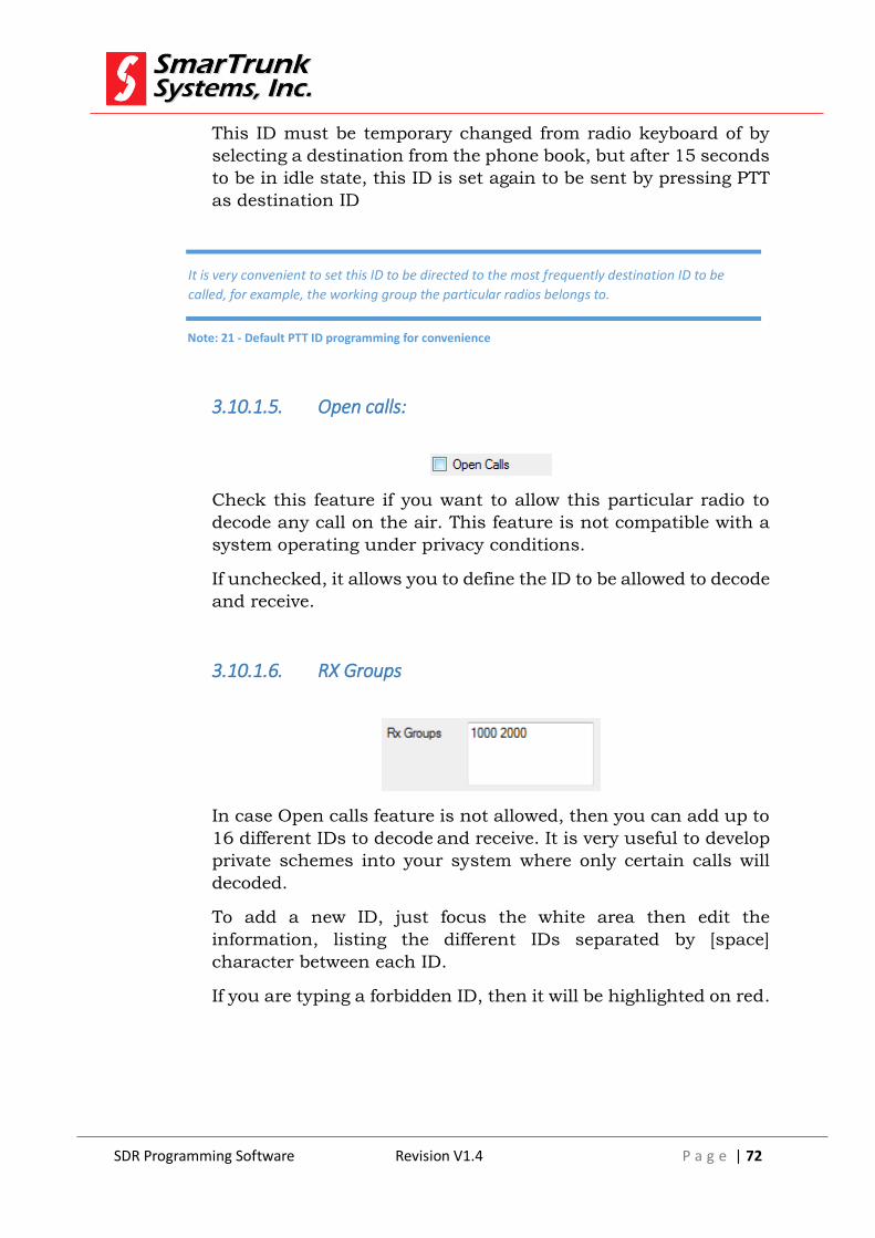
SDR Programming Software Revision V1.4 P a g e | 72
This ID must be temporary changed from radio keyboard of by
selecting a destination from the phone book, but after 15 seconds
to be in idle state, this ID is set again to be sent by pressing PTT
as destination ID
3.10.1.5. Open calls:
Check this feature if you want to allow this particular radio to
decode any call on the air. This feature is not compatible with a
system operating under privacy conditions.
If unchecked, it allows you to define the ID to be allowed to decode
and receive.
3.10.1.6. RX Groups
In case Open calls feature is not allowed, then you can add up to
16 different IDs to decode and receive. It is very useful to develop
private schemes into your system where only certain calls will
decoded.
To add a new ID, just focus the white area then edit the
information, listing the different IDs separated by [space]
character between each ID.
If you are typing a forbidden ID, then it will be highlighted on red.
It is very convenient to set this ID to be directed to the most frequently destination ID to be
called, for example, the working group the particular radios belongs to.
Note: 21 - Default PTT ID programming for convenience

SDR Programming Software Revision V1.4 P a g e | 73
3.10.1.7. Mode
On this tab, you can select the digital mode of operation for the
current profile.
To select the right one, press on the arrow to open the list of
possibilities.
FDMA: 6.25 Khz bandwidth digital transmission @ 4800
bps
TDMA: 12.5 Khz bandwidth transmissions @ 9600 bps
Click on the desired option from the drop list.
3.10.1.8. Wait ACK:
This feature allows the radio with this profile to know if the last
transmission has been correctly repeated through the repeater.
As soon as the user release the PTT, on the repeater queue, the
repeater qualifies such status then the radio who did the last
transmission will decode it to verify such information. In the case
the report sent from the repeater never arrives to the radio or it
arrives with a negative ACK, then the radio will generate an error
tone to report the last transmission never reach the destination
radios.
Check this box if you want the radio decodes de ACK then report
to the user the failed transmissions.
3.10.1.9. Trunking

SDR Programming Software Revision V1.4 P a g e | 74
Mark this box if you want this profile operates over a SDT
trunking architecture
3.10.1.10. Crypto Key
SDR protocol encrypts the data with 16 alphanumeric characters.
This key must be the same into any radio, which must share the
system; otherwise, it is not possible to communicate each other.
3.10.2. Adding a Digital profile:
Digital signaling and operational modes must be defined by profiles
that later are assigned to the different channels in the main
dashboard.
To create a new profile, please click on any existing profile on the
Digital profile screen then press {Insert} into your computer
keyboard to add one more profile into the programming file
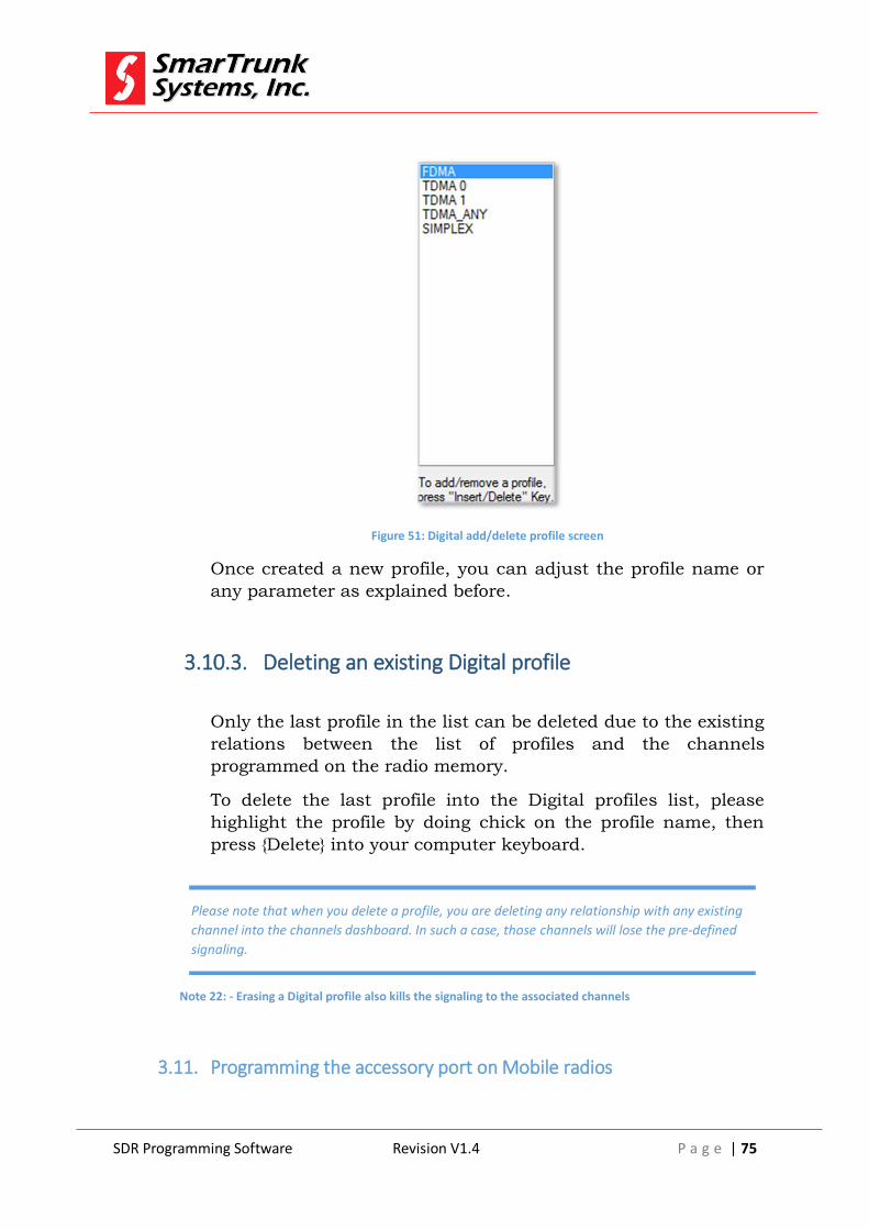
SDR Programming Software Revision V1.4 P a g e | 75
Figure 51: Digital add/delete profile screen
Once created a new profile, you can adjust the profile name or
any parameter as explained before.
3.10.3. Deleting an existing Digital profile
Only the last profile in the list can be deleted due to the existing
relations between the list of profiles and the channels
programmed on the radio memory.
To delete the last profile into the Digital profiles list, please
highlight the profile by doing chick on the profile name, then
press {Delete} into your computer keyboard.
3.11. Programming the accessory port on Mobile radios
Please note that when you delete a profile, you are deleting any relationship with any existing
channel into the channels dashboard. In such a case, those channels will lose the pre-defined
signaling.
Note 22: - Erasing a Digital profile also kills the signaling to the associated channels

SDR Programming Software Revision V1.4 P a g e | 76
ST-3118 mobile radio has a built in accessory port, which includes
many features and services.
In order to access to the programming of the accessory port, please
click on [Edit] then [Accessory Port] on the menu bar
Figure 52: Accessing to the Accessory Port definition Screen
As soon as you click on [Accessory Port], the accessory port
programming screen will pop up.
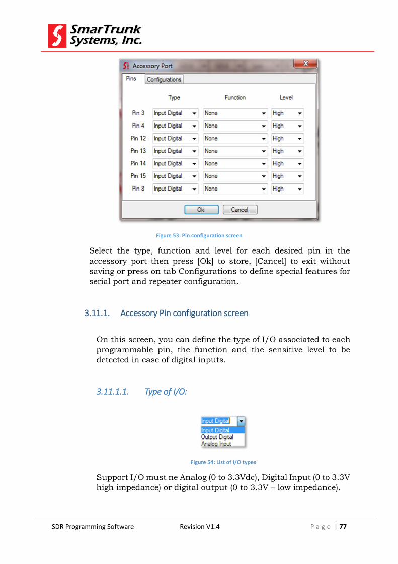
SDR Programming Software Revision V1.4 P a g e | 77
Figure 53: Pin configuration screen
Select the type, function and level for each desired pin in the
accessory port then press [Ok] to store, [Cancel] to exit without
saving or press on tab Configurations to define special features for
serial port and repeater configuration.
3.11.1. Accessory Pin configuration screen
On this screen, you can define the type of I/O associated to each
programmable pin, the function and the sensitive level to be
detected in case of digital inputs.
3.11.1.1. Type of I/O:
Figure 54: List of I/O types
Support I/O must ne Analog (0 to 3.3Vdc), Digital Input (0 to 3.3V
high impedance) or digital output (0 to 3.3V – low impedance).
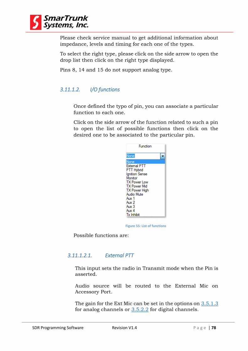
SDR Programming Software Revision V1.4 P a g e | 78
Please check service manual to get additional information about
impedance, levels and timing for each one of the types.
To select the right type, please click on the side arrow to open the
drop list then click on the right type displayed.
Pins 8, 14 and 15 do not support analog type.
3.11.1.2. I/O functions
Once defined the typo of pin, you can associate a particular
function to each one.
Click on the side arrow of the function related to such a pin
to open the list of possible functions then click on the
desired one to be associated to the particular pin.
Figure 55: List of functions
Possible functions are:
3.11.1.2.1. External PTT
This input sets the radio in Transmit mode when the Pin is
asserted.
Audio source will be routed to the External Mic on
Accessory Port.
The gain for the Ext Mic can be set in the options on 3.5.1.3
for analog channels or 3.5.2.2 for digital channels.
SDR Programming Software Revision V1.4 P a g e | 79
Transmission mode for this pin should be according to the channel.
3.11.1.2.2. PTT Hybrid
This pin will set the radio to transmit in hybrid mode.
It is especially useful if the radio will be part of an mixed fleet of analog and digital radios.
3.11.1.2.3. Ignition Sense
This PIN is used connected to the Ignition in cars or trucks
to turn off the radio when the car or truck engine is not running, to avoid the discharge of the vehicle battery.
When this pin is not powered from the ignition switch the radios is powered off, and when the pin is asserted the radio will power up.
This pin can be override using the Power Button.
If the Radio is Powered On, by pressing the power button
will turn off the radio. However, if the radio is off due to the Ignition sense and the power button in the radio is pressed,
the radio will be powered on but a power on timer will switch it off when the time is over. This operational mode will help to the user to use the radio anyway, even when
the ignition if not on.
3.11.1.2.4. Monitor
Enable the Monitor Function in the radio to override any signaling or squelch level.
3.11.1.2.5. TX Power Low
Asserting this pin will set the radio to transmit in the Low
power.
If the pin is released, then the radio will back to its normal power setting
SDR Programming Software Revision V1.4 P a g e | 80
3.11.1.2.6. Audio Mute
Asserting this pin, it mutes the audio to the Speaker.
3.11.1.2.7. Auxiliary Inputs
Auxiliary input to be used as telemetry to read the logic status from a remote location.
3.11.1.2.8. Tx Inhibit
If asserted, this pin will avoid the radio to goes to TX mode.
3.11.1.2.9. Ext Alarm
Output to be controller remotely from remote application
software (telemetry)
3.11.1.2.10. Carrier Detect
This pin is asserted when the RSSI level is higher than the Squelch level.
3.11.1.2.11. Aux Control
Auxiliary outputs, which can be remotely controller
(telemetry)
3.11.1.2.12. Public Address
This pin is asserted when the radio is routing Voice to the Speaker. In analog or digital Mode. This pin is not asserted
when the radio is playing tones or announces, so if the

SDR Programming Software Revision V1.4 P a g e | 81
radio will be used for Public Announces, this pin should be used to control the external amplifier.
3.11.1.2.13. AF Mute
This pin is asserted when the radio is using the speaker for
any kind of sounds, including Tones, Voice, announces etc.
3.11.1.2.14. Transmit
If the radio is transmitting this pin is asserted. Useful in cases when external cooler are required because the radio
will be a long time transmitting. For example, a fan can be turn on/off using this pin to reduce the power consumption.
3.11.1.2.15. Emergency
This pin is asserted if the radio in in emergency mode.
3.11.1.2.16. Sub Audio Detect
When the radio detects the sub audio programmed for the
channel, this pin is asserted
3.11.1.3. Serial port and repeater configuration
Click on Configuration tag on the Accessory pin configuration screen, to access to additional options for
repeater and serial port configuration.
A soon as you click on it, the configuration screen will be launched.

SDR Programming Software Revision V1.4 P a g e | 82
Figure 56: Configuration for serial port and repeater functionality
3.11.1.3.1. Adjusting the Serial port Mode:
Click on the side arrow to open the list of options for the
serial port functionality, then click on the right one to assign it to the port.
Possible serial port functionalities are:

SDR Programming Software Revision V1.4 P a g e | 83
3.11.1.3.2. GPS
Choose this function if the port will be used for interface with a compatible GPS.
3.11.1.3.3. PC (Base station)
Choose this mode to use this radio as a data base station connected to a computer.
3.11.1.3.4. Digital Repeater RX
Choose this option if the radio will be used as receiver into a repeater configuration back to back. This mode supports
also analog and hybrid modes
3.11.1.3.5. Digital Repeater RX:
Choose this option if the radio will be used as transmitter
into a repeater configuration back to back. This mode supports also analog and hybrid modes
3.11.1.3.6. Digital Simplex Repeater Transmitter
Choose this option if the radio will be used as transmitter into a simplex repeater configuration back to back. This
mode does not support analog or hybrid modes
3.11.1.3.7. Digital Simplex Repeater Receiver
Choose this option if the radio will be used as receiver into
a simplex repeater configuration back to back. This mode does not support analog or hybrid modes
Do not connect this port to an RS-232 compatible device. It is TTL levels only. Otherwise
it may be damaged
Note: 23 - Serial port compatibility to TTL level warning

SDR Programming Software Revision V1.4 P a g e | 84
3.11.1.3.8. Adjusting the serial port speed
Click on the side arrow to open the list of compatible speeds then clock on the desired on to store.
Figure 57: List of compatible serial port speed
3.11.1.3.9. Adjusting digital tail for repeater mode
Click on the side arrow to open the list of different tail length then click on the desired one.
3.11.1.4. Setting the Ignition Sense Override Timer
Click on the side arrow to open the list of possible timer
duration to keep the radio on in case the ignition sense is de-asserted. Refer to 3.11.1.2.3 to get details over Ignition sense

SDR Programming Software Revision V1.4 P a g e | 85
Figure 58: List of Ignition sense timer
3.11.1.5. Ext PTT release Time
How long the radio will stay transmitting after the external PTT
was de-asserted. This function is used to control the analog repeater tail.
Click on the side arrow to open the list of possible values for this function.
Figure 59: list of possible values for External PTT release delay
3.12. Programming advanced features
In order to get access to the advanced Programming features, you
must chick on [Menu] then [Advanced].

SDR Programming Software Revision V1.4 P a g e | 86
As soon as you click on advanced, the advanced features screen
will pop up.
3.12.1. Radio Announcement Update
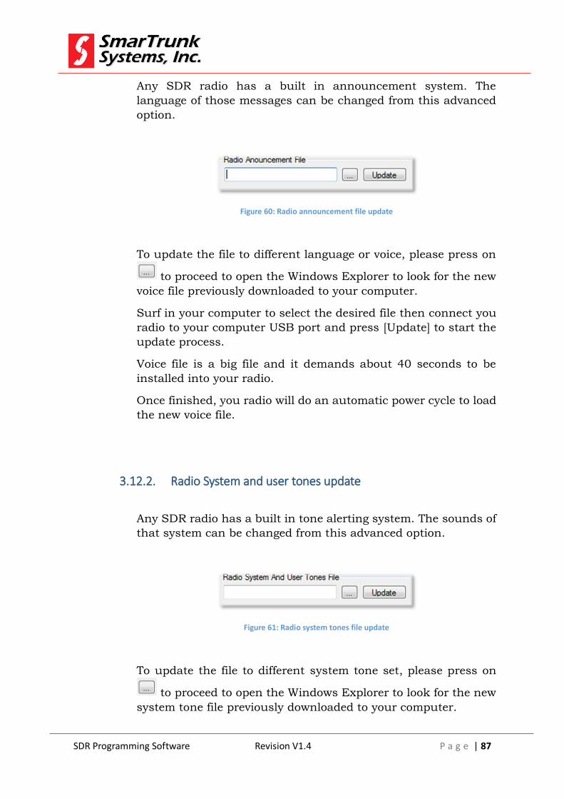
SDR Programming Software Revision V1.4 P a g e | 87
Any SDR radio has a built in announcement system. The
language of those messages can be changed from this advanced
option.
Figure 60: Radio announcement file update
To update the file to different language or voice, please press on
to proceed to open the Windows Explorer to look for the new
voice file previously downloaded to your computer.
Surf in your computer to select the desired file then connect you
radio to your computer USB port and press [Update] to start the
update process.
Voice file is a big file and it demands about 40 seconds to be
installed into your radio.
Once finished, you radio will do an automatic power cycle to load
the new voice file.
3.12.2. Radio System and user tones update
Any SDR radio has a built in tone alerting system. The sounds of
that system can be changed from this advanced option.
Figure 61: Radio system tones file update
To update the file to different system tone set, please press on
to proceed to open the Windows Explorer to look for the new
system tone file previously downloaded to your computer.
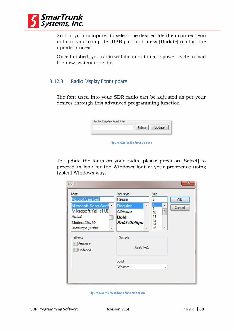
SDR Programming Software Revision V1.4 P a g e | 88
Surf in your computer to select the desired file then connect you
radio to your computer USB port and press [Update] to start the
update process.
Once finished, you radio will do an automatic power cycle to load
the new system tone file.
3.12.3. Radio Display Font update
The font used into your SDR radio can be adjusted as per your
desires through this advanced programming function
Figure 62: Radio font update
To update the fonts on your radio, please press on [Select] to
proceed to look for the Windows font of your preference using
typical Windows way.
Figure 63: MS Windows font selection

SDR Programming Software Revision V1.4 P a g e | 89
Once selected the font of your preference, please press [Ok] or
press [Cancel] to exit
Once selected the right font, press [Update] to transfer the new
font to your radio. This process may take about 30 seconds.
Once finished, you radio will do an automatic power cycle to load
the new font file.
3.12.4. Radio Presentation Slide Show update
When the radio is powered on, a short movie composed by 8
frames are displayed.
You can change the movie using this advance feature.
To update the file to different slide show, please press on to
proceed to open the Windows Explorer to look for the new
presentation file previously downloaded to your computer.
Surf in your computer to select the desired file then connect you
radio to your computer USB port and press [Update] to start the
update process.
Presentation movie file is a big file and it demands about 40
seconds to be installed into your radio.
Once finished, you radio will do an automatic power cycle to load
the new presentation file.
3.12.5. Radio FI files update
Some font may be not appropriate for SmarTrunk radio display resolution. In such a case try a
different font to read it easy.
Note: 24 - inappropriate font warning
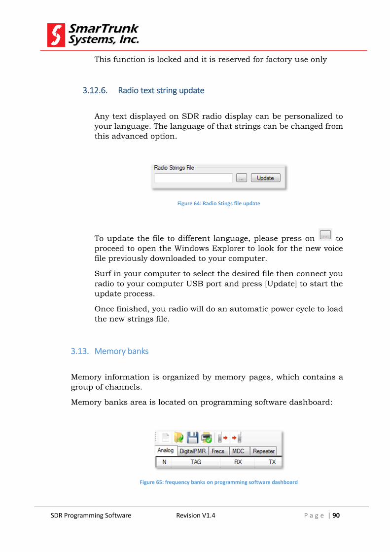
SDR Programming Software Revision V1.4 P a g e | 90
This function is locked and it is reserved for factory use only
3.12.6. Radio text string update
Any text displayed on SDR radio display can be personalized to
your language. The language of that strings can be changed from
this advanced option.
Figure 64: Radio Stings file update
To update the file to different language, please press on to
proceed to open the Windows Explorer to look for the new voice
file previously downloaded to your computer.
Surf in your computer to select the desired file then connect you
radio to your computer USB port and press [Update] to start the
update process.
Once finished, you radio will do an automatic power cycle to load
the new strings file.
3.13. Memory banks
Memory information is organized by memory pages, which contains a
group of channels.
Memory banks area is located on programming software dashboard:
Figure 65: frequency banks on programming software dashboard
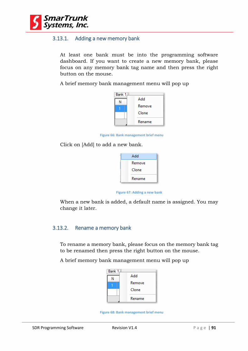
SDR Programming Software Revision V1.4 P a g e | 91
3.13.1. Adding a new memory bank
At least one bank must be into the programming software
dashboard. If you want to create a new memory bank, please
focus on any memory bank tag name and then press the right
button on the mouse.
A brief memory bank management menu will pop up
Figure 66: Bank management brief menu
Click on [Add] to add a new bank.
Figure 67: Adding a new bank
When a new bank is added, a default name is assigned. You may
change it later.
3.13.2. Rename a memory bank
To rename a memory bank, please focus on the memory bank tag
to be renamed then press the right button on the mouse.
A brief memory bank management menu will pop up
Figure 68: Bank management brief menu
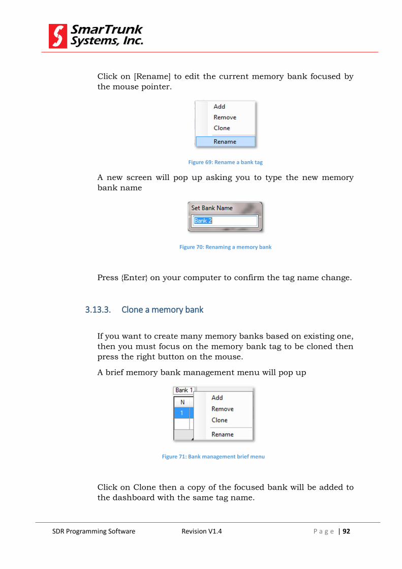
SDR Programming Software Revision V1.4 P a g e | 92
Click on [Rename] to edit the current memory bank focused by
the mouse pointer.
Figure 69: Rename a bank tag
A new screen will pop up asking you to type the new memory
bank name
Figure 70: Renaming a memory bank
Press {Enter} on your computer to confirm the tag name change.
3.13.3. Clone a memory bank
If you want to create many memory banks based on existing one,
then you must focus on the memory bank tag to be cloned then
press the right button on the mouse.
A brief memory bank management menu will pop up
Figure 71: Bank management brief menu
Click on Clone then a copy of the focused bank will be added to
the dashboard with the same tag name.
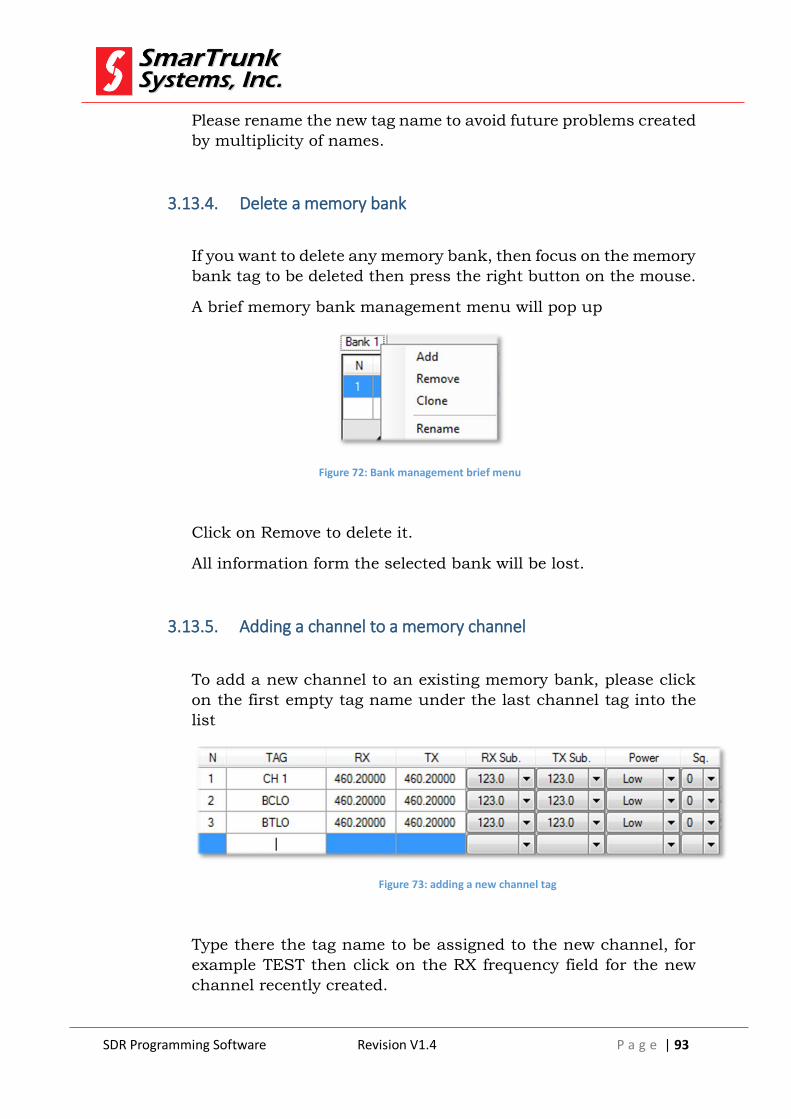
SDR Programming Software Revision V1.4 P a g e | 93
Please rename the new tag name to avoid future problems created
by multiplicity of names.
3.13.4. Delete a memory bank
If you want to delete any memory bank, then focus on the memory
bank tag to be deleted then press the right button on the mouse.
A brief memory bank management menu will pop up
Figure 72: Bank management brief menu
Click on Remove to delete it.
All information form the selected bank will be lost.
3.13.5. Adding a channel to a memory channel
To add a new channel to an existing memory bank, please click
on the first empty tag name under the last channel tag into the
list
Figure 73: adding a new channel tag
Type there the tag name to be assigned to the new channel, for
example TEST then click on the RX frequency field for the new
channel recently created.
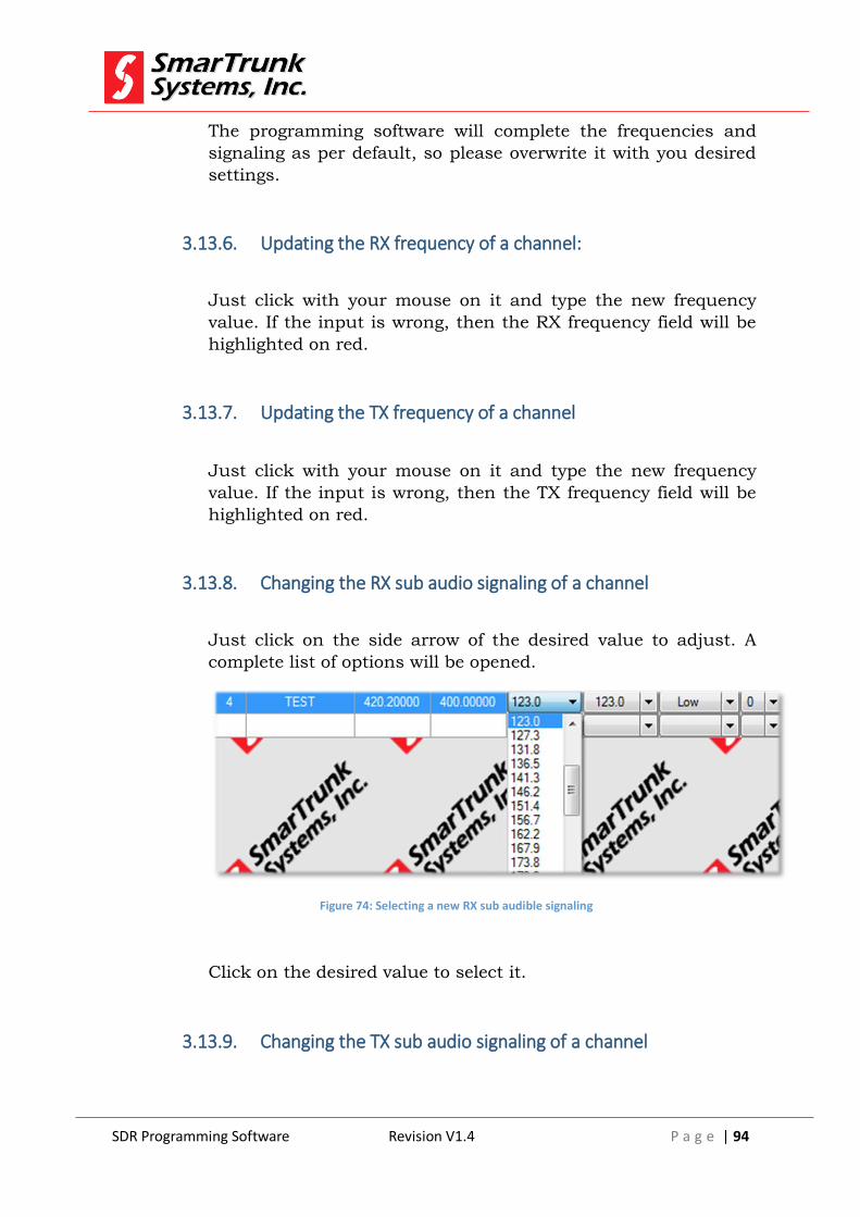
SDR Programming Software Revision V1.4 P a g e | 94
The programming software will complete the frequencies and
signaling as per default, so please overwrite it with you desired
settings.
3.13.6. Updating the RX frequency of a channel:
Just click with your mouse on it and type the new frequency
value. If the input is wrong, then the RX frequency field will be
highlighted on red.
3.13.7. Updating the TX frequency of a channel
Just click with your mouse on it and type the new frequency
value. If the input is wrong, then the TX frequency field will be
highlighted on red.
3.13.8. Changing the RX sub audio signaling of a channel
Just click on the side arrow of the desired value to adjust. A
complete list of options will be opened.
Figure 74: Selecting a new RX sub audible signaling
Click on the desired value to select it.
3.13.9. Changing the TX sub audio signaling of a channel
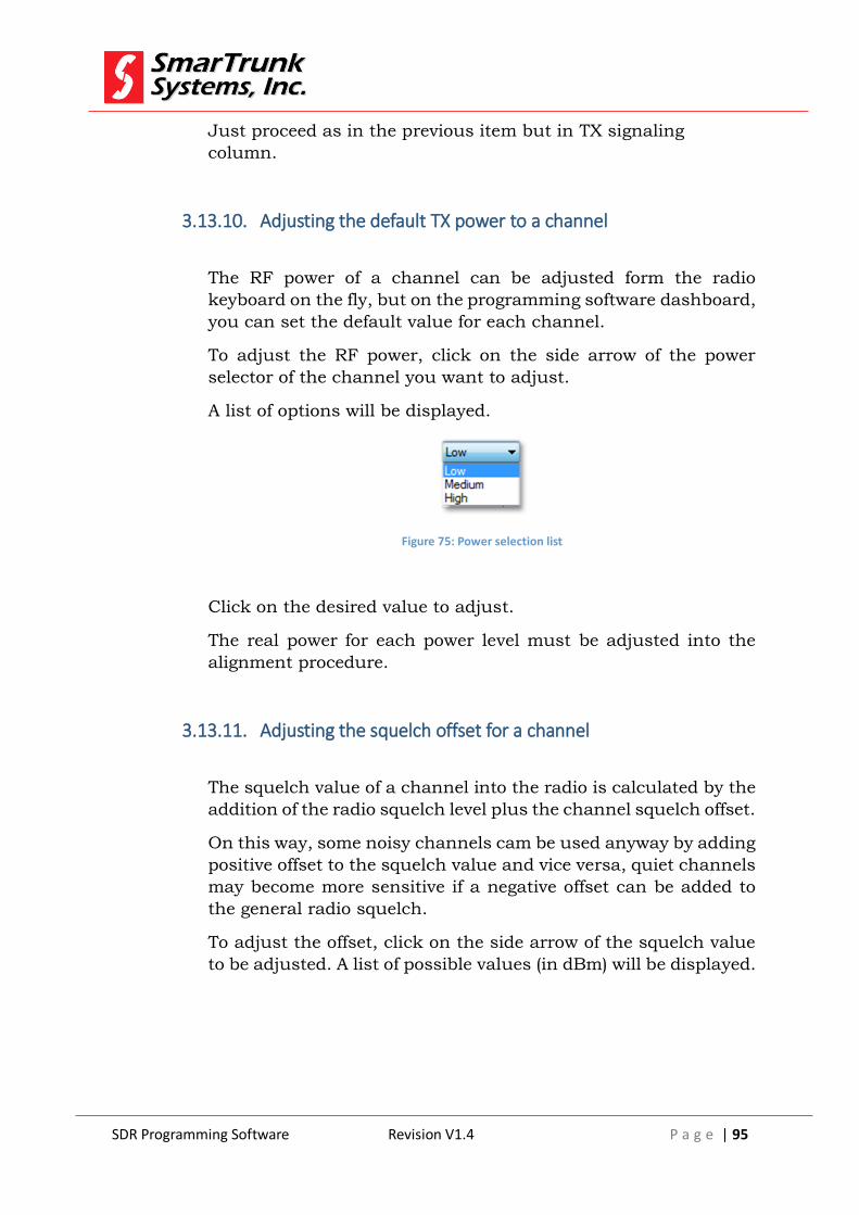
SDR Programming Software Revision V1.4 P a g e | 95
Just proceed as in the previous item but in TX signaling
column.
3.13.10. Adjusting the default TX power to a channel
The RF power of a channel can be adjusted form the radio
keyboard on the fly, but on the programming software dashboard,
you can set the default value for each channel.
To adjust the RF power, click on the side arrow of the power
selector of the channel you want to adjust.
A list of options will be displayed.
Figure 75: Power selection list
Click on the desired value to adjust.
The real power for each power level must be adjusted into the
alignment procedure.
3.13.11. Adjusting the squelch offset for a channel
The squelch value of a channel into the radio is calculated by the
addition of the radio squelch level plus the channel squelch offset.
On this way, some noisy channels cam be used anyway by adding
positive offset to the squelch value and vice versa, quiet channels
may become more sensitive if a negative offset can be added to
the general radio squelch.
To adjust the offset, click on the side arrow of the squelch value
to be adjusted. A list of possible values (in dBm) will be displayed.

SDR Programming Software Revision V1.4 P a g e | 96
Figure 76: Squelch offset setting
Click on the desire value to save it.
3.14. Advanced channel configuration
After the basic channel information has been loaded, you must double
click on the channel number to access to the advanced features
programming screen.
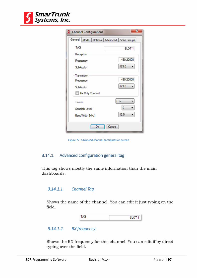
SDR Programming Software Revision V1.4 P a g e | 97
Figure 77: advanced channel configuration screen
3.14.1. Advanced configuration general tag
This tag shows mostly the same information than the main
dashboards.
3.14.1.1. Channel Tag
Shows the name of the channel. You can edit it just typing on the
field.
3.14.1.2. RX frequency:
Shows the RX frequency for this channel. You can edit if by direct
typing over the field.

SDR Programming Software Revision V1.4 P a g e | 98
Figure 78: Channel RX information
3.14.1.3. RX sub Audio Signaling:
Shows the CTCSS or DCS information for the current channel.
Click on the side arrow then select a different one if you want to
change it.
3.14.1.4. TX frequency:
Shows the TX frequency for this channel. You can edit if by direct
typing over the field.
Figure 79: Channel TX information
3.14.1.5. TX sub Audio Signaling:
Shows the CTCSS or DCS information for the current channel.
Click on the side arrow then select a different one if you want to
change it.
3.14.1.6. RX Only Channel
Check this box if you want to deny the transmission on current
channel.
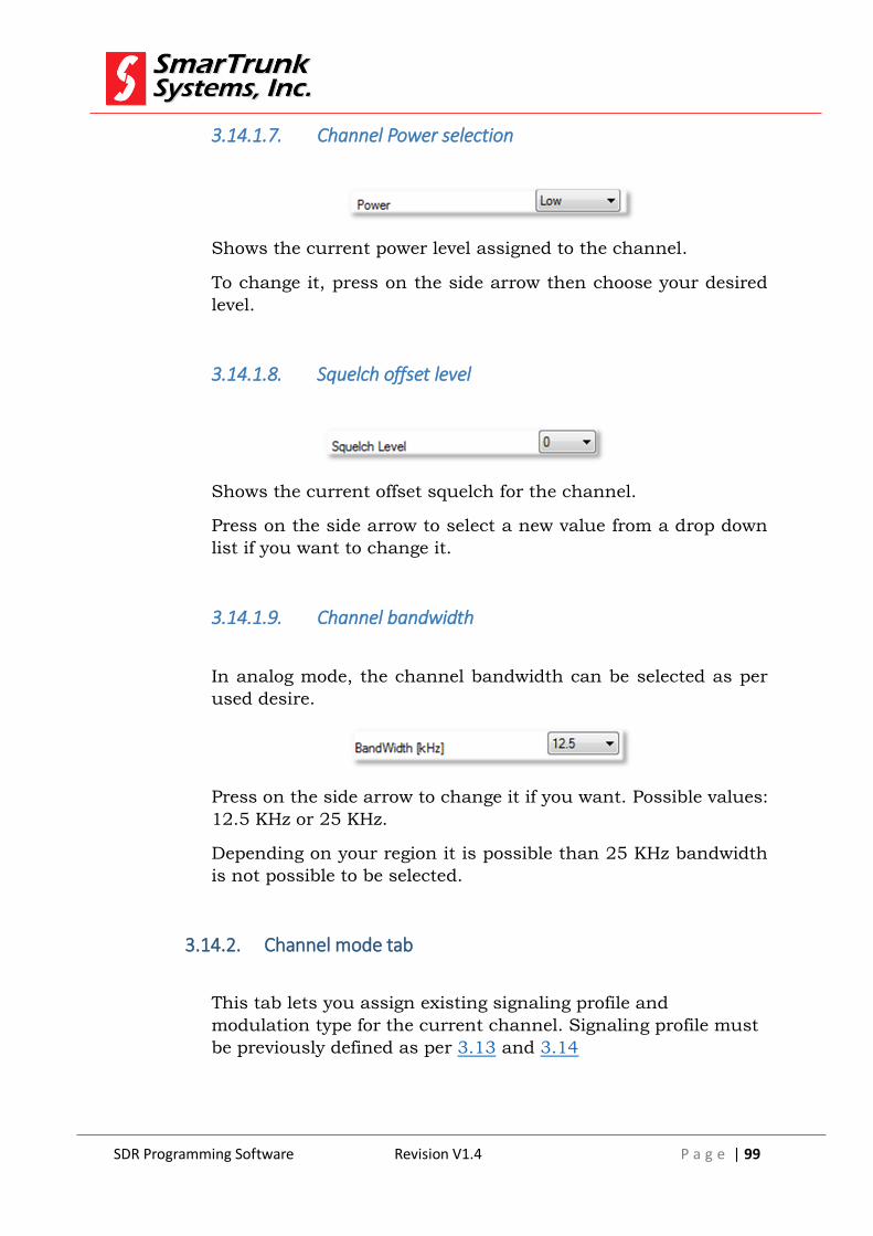
SDR Programming Software Revision V1.4 P a g e | 99
3.14.1.7. Channel Power selection
Shows the current power level assigned to the channel.
To change it, press on the side arrow then choose your desired
level.
3.14.1.8. Squelch offset level
Shows the current offset squelch for the channel.
Press on the side arrow to select a new value from a drop down
list if you want to change it.
3.14.1.9. Channel bandwidth
In analog mode, the channel bandwidth can be selected as per
used desire.
Press on the side arrow to change it if you want. Possible values:
12.5 KHz or 25 KHz.
Depending on your region it is possible than 25 KHz bandwidth
is not possible to be selected.
3.14.2. Channel mode tab
This tab lets you assign existing signaling profile and
modulation type for the current channel. Signaling profile must
be previously defined as per 3.13 and 3.14

SDR Programming Software Revision V1.4 P a g e | 100
Figure 80: Channel mode tab
Once selected the with parameters, press [Ok], press over
other tab to save it or [Cancel] to exit.
3.14.2.1. Channel function:
The type of signaling/modulation can be selected on this
tab.
To select a desired one press on the side arrow. A list the
options will be displayed.
Figure 81: type of modulation
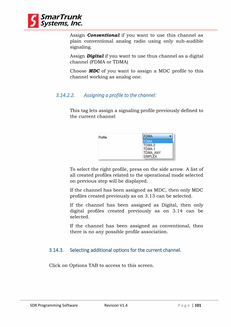
SDR Programming Software Revision V1.4 P a g e | 101
Assign Conventional if you want to use this channel as
plain conventional analog radio using only sub-audible
signaling.
Assign Digital if you want to use thus channel as a digital
channel (FDMA or TDMA)
Choose MDC of you want to assign a MDC profile to this
channel working as analog one.
3.14.2.2. Assigning a profile to the channel:
This tag lets assign a signaling profile previously defined to
the current channel
To select the right profile, press on the side arrow. A list of
all created profiles related to the operational mode selected
on previous step will be displayed.
If the channel has been assigned as MDC, then only MDC
profiles created previously as on 3.13 can be selected.
If the channel has been assigned as Digital, then only
digital profiles created previously as on 3.14 can be
selected.
If the channel has been assigned as conventional, then
there is no any possible profile association.
3.14.3. Selecting additional options for the current channel.
Click on Options TAB to access to this screen.

SDR Programming Software Revision V1.4 P a g e | 102
Figure 82: option tab advanced programming
Advanced options must be accessible depending on the type of
modulation selected o Mode tag.
3.14.3.1. Power Saving
Enable this function if the radio is allowed to enter in power saver
mode for this channel. The power saving feature is extremely efficient and sets most of the radio in sleep mode for 200 milliseconds with a very low current demand. It wakes up by
carried detection, button keyed, etc.
If this channel must decode some type of signaling, special
considerations must be taken because wake up process may delay the signaling decoding process, losing some information. In
this case, longer pre-transmission warm up must be considered.

SDR Programming Software Revision V1.4 P a g e | 103
3.14.3.2. Priority
Set this channel as the priority channel for the radio. Priority channel is used for priority scan, revert channel, direct channel.
3.14.3.3. Man Down
Enables the Man Down Function for this channel. According to the signaling mode selected for the channel the Man Down event will be reported.
`
3.14.3.4. Man Running
This function allows the administrator to know when a radio matches to the movement pattern for a Man Running. Like in the Man Down function the parameters are set in a different window
and the transitions mode depends on the selected channel function
3.14.3.5. Compander
Enable the audio compander function for this channel
3.14.3.6. Pre/De - Emphasis
Enable the Pre-Emphasis in Transition and the De-Emphasis in
reception for the current channel
3.14.3.7. Busy Channel Lock Out
When this function is set, the user can only transmit when the channel is free.
A channel is free when there is not carrier or in case the channel
has Sub-Audio programmed for reception, the radio do not detect the right Sub-Audio.
If the channel is in digital mode a channel is busy when is receiving a valid data frame.
SDR Programming Software Revision V1.4 P a g e | 104
3.14.3.8. Busy Tone Lock Tone
When this function is enabled, the user can press PTT only when
the radio does not detect carrier or the Receive Sub Audio matches to the programed as reception sub audio. This function
is useful in Pseudo-Trunking where the repeater has a tail and only are able to talk between them users programed with the
same reception Sub Audio.
3.14.3.9. Vox
Enables the VOX function for this channel. Vox function parameters are set in the "Options" windows and the Vox trigger
level can be changed on the fly by the user using the buttons or the radio rotary.
3.14.3.10. Beat
This function beat a bit the radio main clock so transmit or receive frequency is not a multiple of the main radio clock.
3.14.3.11. Data Channel
This option set the audio channel completely flat so the radio channel can be used to transmit any external modem signal.
3.14.3.12. Hybrid Mode
If it is enabled, this option allows the user to use the channel as analog also meantime the channel is programmed as a Digital
Channel.
For reception the transition is automatic, this means the radio
will automatically change to analog if detects that the sub audio received matches to the programmed in the channel.

SDR Programming Software Revision V1.4 P a g e | 105
After the radio changes to analog, it will stay in this mode for 20 seconds. This mode ends also if a digital transition is received.
Hybrid timer is extended 20 more seconds if the radio decodes sub audio or the user press PTT.
If the user press PTT within the 20 seconds the radio will transmit
in analog mode using the sub audio programmed for encoding.
When this mode is enabled in the radios display, the "HYB" icon
is show.
This way the user is able to maintain a conversation with an old
radio or a group of old radios, this is special useful in systems when not all radios has been changed to digital yet.
"Clear Hybrid Mode" function can be assigned to any function
button to exit from this mode.
3.14.4. Advanced channel functions:
Press on Advanced tab to access to this screen

SDR Programming Software Revision V1.4 P a g e | 106
Figure 83: advanced functionality
3.14.4.1. TOT (Time out Timer)
This function allows the administrator to prevent a user to keep
transmitting too much time setting the shared channel busy long time. Check this box to activate this feature.
3.18.4.1.1 Timer
Set the maximum time the user can transmit continuously
over this channel.
3.18.4.1.2 Penalty
When the maximum TOT is reached for how long the user has
to wait to be able to transmit again.
SDR Programming Software Revision V1.4 P a g e | 107
3.18.4.1.3 Release
How long the user has to de key the PTT button to reset the
time out timer and start the time out count again, this feature is to avoid the user to de key and key immediately when the
time out limit is approaching.
3.14.4.2. Scrambler
Enables or disables the scrambler function for this channel. Once the scrambler function is enabled, the user can change the
inversion frequency for the scrambler function by typing on the associated field
3.14.5. Scan Group
On this tab you can select to which scan group this channel will be
included, if do not belong to any groups or the radio do not have any scan group, this parameter has to be set to no data.

SDR Programming Software Revision V1.4 P a g e | 108
Figure 84: Scan groups
Press [Ok] to save the changes of [Cancel] to exit.
3.15. Reading the radio file
All the information already downloaded to your radio can be retrieved
anytime.
In case that information has been protected by password, you must
know such critical information to start the reading process.
To read the radio file from the radio, you must connect the radio to the
USB port on your computer, then you can use the shortcut in the quick
access bar or you go through [Radio] then click on Read Radio. F2
key on your computer keyboard can be used as a shortcut also.
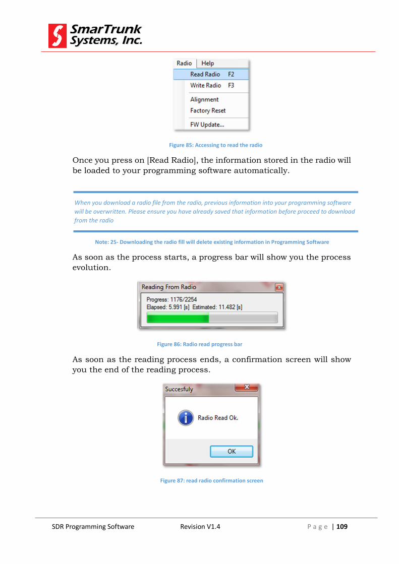
SDR Programming Software Revision V1.4 P a g e | 109
Figure 85: Accessing to read the radio
Once you press on [Read Radio], the information stored in the radio will
be loaded to your programming software automatically.
As soon as the process starts, a progress bar will show you the process
evolution.
Figure 86: Radio read progress bar
As soon as the reading process ends, a confirmation screen will show
you the end of the reading process.
Figure 87: read radio confirmation screen
When you download a radio file from the radio, previous information into your programming software
will be overwritten. Please ensure you have already saved that information before proceed to download
from the radio
Note: 25- Downloading the radio fill will delete existing information in Programming Software
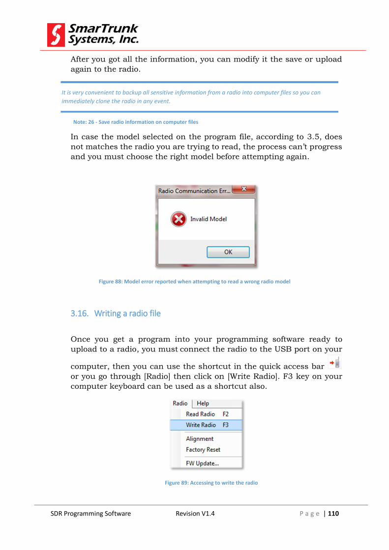
SDR Programming Software Revision V1.4 P a g e | 110
After you got all the information, you can modify it the save or upload
again to the radio.
In case the model selected on the program file, according to 3.5, does
not matches the radio you are trying to read, the process can’t progress
and you must choose the right model before attempting again.
Figure 88: Model error reported when attempting to read a wrong radio model
3.16. Writing a radio file
Once you get a program into your programming software ready to
upload to a radio, you must connect the radio to the USB port on your
computer, then you can use the shortcut in the quick access bar
or you go through [Radio] then click on [Write Radio]. F3 key on your
computer keyboard can be used as a shortcut also.
Figure 89: Accessing to write the radio
It is very convenient to backup all sensitive information from a radio into computer files so you can
immediately clone the radio in any event.
Note: 26 - Save radio information on computer files
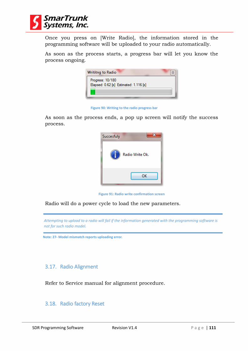
SDR Programming Software Revision V1.4 P a g e | 111
Once you press on [Write Radio], the information stored in the
programming software will be uploaded to your radio automatically.
As soon as the process starts, a progress bar will let you know the
process ongoing.
Figure 90: Writing to the radio progress bar
As soon as the process ends, a pop up screen will notify the success
process.
Figure 91: Radio write confirmation screen
Radio will do a power cycle to load the new parameters.
3.17. Radio Alignment
Refer to Service manual for alignment procedure.
3.18. Radio factory Reset
Attempting to upload to a radio will fail if the information generated with the programming software is
not for such radio model.
Note: 27- Model mismatch reports uploading error.

SDR Programming Software Revision V1.4 P a g e | 112
In case the radio has been realigned by somebody who does not
understand the procedure correctly or any other problem, which affect
to the radio performance, you can reset as per initial factory settings.
This process will erase all the information on your radio, which cannot
be recovered except from backup on computer files.
To proceed to reset he radio as per factory default, please click on
[Radio] then [Factory Reset]
Figure 92: Accessing to restore factory default settings
As soon as you click on [Factory Reset] a warning message will alert you
about the process ready to go. If you are not sure, please press [Cancel].
If you agree, please press [Yes] to continue.
Figure 93: warning message before restoring factory default
As soon as you press [Yes] the process starts. It demands only two
seconds, and then the confirmation message is displayed:

SDR Programming Software Revision V1.4 P a g e | 113
Figure 94: Factory default settings confirmation
As soon as this process ends, the radio will do a power cycle to load the
new parameters.
3.19. Radio Firmware Update:
Smartrunk will continue working to develop new features and services
for our radios so frequently you will find firmware updates into our web
site.
To download a new firmware to you radio, once you have downloaded it
into your computer, please clock on [Radio] then [FW Update]
Figure 95: Accessing to Radio firmware update screen
A soon as you click on [FW Update] a new screen will pop up.

SDR Programming Software Revision V1.4 P a g e | 114
Figure 96: radio FW Update application screen
To find the new firmware to be downloaded to the radio press to
proceed to open the Windows Explorer to look for the new voice file
previously downloaded to your computer.
Surf in your computer to select the desired file then connect you radio
to your computer USB port and press [Start] to initiate the firmware
update process.
A progress bar will show you the process progress.
Figure 97: Firmware update progress screen
Uploading a wrong firmware to your radio may cause a permanent damage to the circuitry.
Please verify several times that you are ready to upload a firmware version corresponding to
your radio model.
Note: 28 - Wrong model firmware upload warning
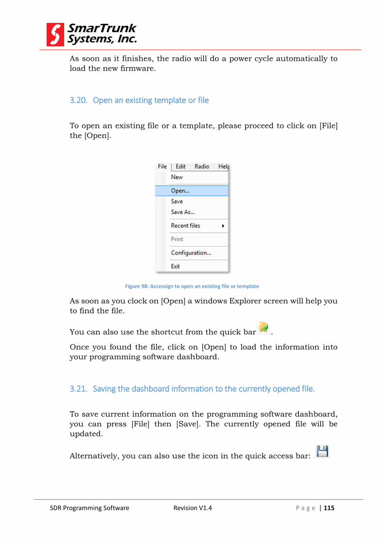
SDR Programming Software Revision V1.4 P a g e | 115
As soon as it finishes, the radio will do a power cycle automatically to
load the new firmware.
3.20. Open an existing template or file
To open an existing file or a template, please proceed to click on [File]
the [Open].
Figure 98: Accessign to open an existing file or template
As soon as you clock on [Open] a windows Explorer screen will help you
to find the file.
You can also use the shortcut from the quick bar .
Once you found the file, click on [Open] to load the information into
your programming software dashboard.
3.21. Saving the dashboard information to the currently opened file.
To save current information on the programming software dashboard,
you can press [File] then [Save]. The currently opened file will be
updated.
Alternatively, you can also use the icon in the quick access bar:

SDR Programming Software Revision V1.4 P a g e | 116
3.22. Saving current dashboard into different file
To save current information on the programming software dashboard
but in different file, you can press [File] then [Save As].
A typical windows Explorer screen will prompt you to type the desired
file name and find the file location. Once selected it, the information will
be saved into the file.
If the selected file name exist, the software will alert you to before
overwrite it.
3.23. Exit from Programming software
To exit from the programming software please proceed through [File]
then [Exit]
Figure 99: Exit from SDR programming software
3.24. Manual software update
Before exit verify if the current data has been saved. Any change will be lost.
Note: 29 - lost data on exit warning note

SDR Programming Software Revision V1.4 P a g e | 117
In case the automatic software update is not active (see 2.4.3), then you
can check for new updates by clicking on [Help] then [Software Update]
Figure 100: Manually checking firmware update
The software will look for the latest release in our web site. If your
software is up to date, then a confirmation screen will pop up.
Figure 101: Software up to date confirmation screen
If no, the new software will be downloaded automatically.
Proceed to install the new software as descripted on 3.1
SDR Programming Software Revision V1.4 P a g e | 118
List of Figures
Figure 3: SDR programming software welcome screen ......................................................................... 7
Figure 4: SDR programming software file location setup ...................................................................... 8
Figure 5: Start Menu destination .......................................................................................................... 9
Figure 6: Additional task to be performed by installation software .................................................... 10
Figure 7: Installation parameters review ............................................................................................. 11
Figure 8: SDR Installation Software Final Screen ................................................................................. 12
Figure 9: Programming Software Main Screen Functional Areas ........................................................ 14
Figure 10: SDR Programming Software Configuration Access ............................................................ 17
Figure 11: SDR Programming Software Configuration Screen ............................................................. 17
Figure 12: Software Language Configuration Screen........................................................................... 19
Figure 13: Automatic Update Checkbox .............................................................................................. 19
Figure 14: Region change .................................................................................................................... 20
Figure 15: warning message about changing software zone ............................................................... 20
Figure 16: New file access through File menu ..................................................................................... 21
Figure 17: Model information access through Edit Menu ................................................................... 22
Figure 18: Model Info Screen .............................................................................................................. 22
Figure 19: Accessing to Radio Buttons screen ..................................................................................... 24
Figure 20: Buttons Definition screen ................................................................................................... 25
Figure 21: Accessing to the scan menu ............................................................................................... 36
Figure 22: Scan groups programming screen ...................................................................................... 36
Figure 23: Scan tag assignment to one scan group ............................................................................. 37
Figure 24: Access to the Emergency Programming menu through Menu bar ..................................... 40
Figure 25: Emergency programming screen ........................................................................................ 41
Figure 26: Option screen access through Menu bar ........................................................................... 42
Figure 27: Options Program screen ..................................................................................................... 43
Figure 28: Analog mic gain screen ....................................................................................................... 43
Figure 29: Analog mic gain selection ................................................................................................... 44
Figure 30: External PTT mic gain setup screen .................................................................................... 45
Figure 31: Digital mic gain screen........................................................................................................ 45
Figure 32: Digital AGC target selection ................................................................................................ 46
Figure 33: Digital mic gain selection .................................................................................................... 46
Figure 34: External PTT mic gain setup screen for digital mode .......................................................... 47
Figure 35: Minimum volume level programming ................................................................................ 47
Figure 36: Clone screen settings ......................................................................................................... 48
Figure 37: Power Up Mode control box .............................................................................................. 49
Figure 38: Power on mode selection ................................................................................................... 50
Figure 39: Access to Passwords programming screen ......................................................................... 51
Figure 40: User and Dealer password protection screen .................................................................... 51
Figure 41: Access to the contacts programming screen from Menu Bar ............................................. 53
Figure 42: Phone book screen ............................................................................................................. 54
Figure 43: Accessing to the Appearance configuration screen ............................................................ 55
Figure 44: Display/Leds configuration screen ..................................................................................... 56
Figure 45: Auto backlight hold-on delay programming ....................................................................... 57
Figure 46: Leds control area ................................................................................................................ 57
Figure 47: Radio tones configuration screen ....................................................................................... 58
SDR Programming Software Revision V1.4 P a g e | 119
Figure 48: Accessing to the MDC signaling configuration screen ........................................................ 63
Figure 49: MDC Signaling control screen............................................................................................. 63
Figure 50: Advanced MDC signaling screen ........................................................................................ 66
Figure 51: MDC add/delete profile screen .......................................................................................... 68
Figure 52: Access to Digital Profiles programming screen ................................................................... 69
Figure 53: Digital add/delete profile screen ........................................................................................ 75
Figure 54: Accessing to the Accessory Port definition Screen ............................................................. 76
Figure 55: Pin configuration screen ..................................................................................................... 77
Figure 56: List of I/O types .................................................................................................................. 77
Figure 57: List of functions .................................................................................................................. 78
Figure 58: Configuration for serial port and repeater functionality .................................................... 82
Figure 59: List of compatible serial port speed ................................................................................... 84
Figure 60: List of Ignition sense timer ................................................................................................. 85
Figure 61: list of possible values for External PTT release delay.......................................................... 85
Figure 62: Radio announcement file update ....................................................................................... 87
Figure 63: Radio system tones file update .......................................................................................... 87
Figure 64: Radio font update .............................................................................................................. 88
Figure 65: MS Windows font selection................................................................................................ 88
Figure 66: Radio Stings file update ...................................................................................................... 90
Figure 67: frequency banks on programming software dashboard ..................................................... 90
Figure 68: Bank management brief menu ........................................................................................... 91
Figure 69: Adding a new bank ............................................................................................................. 91
Figure 70: Bank management brief menu ........................................................................................... 91
Figure 71: Rename a bank tag ............................................................................................................. 92
Figure 72: Renaming a memory bank ................................................................................................. 92
Figure 73: Bank management brief menu ........................................................................................... 92
Figure 74: Bank management brief menu ........................................................................................... 93
Figure 75: adding a new channel tag .................................................................................................. 93
Figure 76: Selecting a new RX sub audible signaling ........................................................................... 94
Figure 77: Power selection list ............................................................................................................ 95
Figure 78: Squelch offset setting ......................................................................................................... 96
Figure 79: advanced channel configuration screen ............................................................................. 97
Figure 80: Channel RX information ..................................................................................................... 98
Figure 81: Channel TX information...................................................................................................... 98
Figure 82: Channel mode tab ............................................................................................................ 100
Figure 83: type of modulation........................................................................................................... 100
Figure 84: option tab advanced programming .................................................................................. 102
Figure 85: advanced functionality ..................................................................................................... 106
Figure 86: Scan groups ...................................................................................................................... 108
Figure 87: Accessing to read the radio .............................................................................................. 109
Figure 88: Radio read progress bar ................................................................................................... 109
Figure 89: read radio confirmation screen ........................................................................................ 109
Figure 90: Model error reported when attempting to read a wrong radio model ............................ 110
Figure 91: Accessing to write the radio ............................................................................................. 110
Figure 92: Writing to the radio progress bar ..................................................................................... 111
Figure 93: Radio write confirmation screen ...................................................................................... 111
Figure 94: Accessing to restore factory default settings .................................................................... 112

SDR Programming Software Revision V1.4 P a g e | 120
Figure 95: warning message before restoring factory default ........................................................... 112
Figure 96: Factory default settings confirmation .............................................................................. 113
Figure 97: Accessing to Radio firmware update screen..................................................................... 113
Figure 98: radio FW Update application screen ................................................................................ 114
Figure 99: Firmware update progress screen .................................................................................... 114
Figure 100: Accessign to open an existing file or template ............................................................... 115
Figure 101: Exit from SDR programming software ............................................................................ 116
Figure 102: Manually checking firmware update .............................................................................. 117
Figure 103: Software up to date confirmation screen ....................................................................... 117