ICM-to-ICM Gateway User Guide for Cisco Unified ICM Enterprise … · ICM-to-ICM Gateway User Guide...
34
Americas Headquarters Cisco Systems, Inc. 170 West Tasman Drive San Jose, CA 95134-1706 USA http://www.cisco.com Tel: 408 526-4000 800 553-NETS (6387) Fax: 408 527-0883 ICM-to-ICM Gateway User Guide for Cisco Unified ICM Enterprise & Hosted Release 7.5(1) June 2009
-
Upload
vuongthien -
Category
Documents
-
view
297 -
download
0
Transcript of ICM-to-ICM Gateway User Guide for Cisco Unified ICM Enterprise … · ICM-to-ICM Gateway User Guide...

Americas HeadquartersCisco Systems, Inc.170 West Tasman DriveSan Jose, CA 95134-1706 USAhttp://www.cisco.comTel: 408 526-4000
800 553-NETS (6387)Fax: 408 527-0883
ICM-to-ICM Gateway User Guide for Cisco Unified ICM Enterprise & HostedRelease 7.5(1) June 2009

THE SPECIFICATIONS AND INFORMATION REGARDING THE PRODUCTS IN THIS MANUAL ARE SUBJECT TO CHANGE WITHOUT NOTICE. ALL STATEMENTS, INFORMATION, AND RECOMMENDATIONS IN THIS MANUAL ARE BELIEVED TO BE ACCURATE BUT ARE PRESENTED WITHOUT WARRANTY OF ANY KIND, EXPRESS OR IMPLIED. USERS MUST TAKE FULL RESPONSIBILITY FOR THEIR APPLICATION OF ANY PRODUCTS.
THE SOFTWARE LICENSE AND LIMITED WARRANTY FOR THE ACCOMPANYING PRODUCT ARE SET FORTH IN THE INFORMATION PACKET THAT SHIPPED WITH THE PRODUCT AND ARE INCORPORATED HEREIN BY THIS REFERENCE. IF YOU ARE UNABLE TO LOCATE THE SOFTWARE LICENSE OR LIMITED WARRANTY, CONTACT YOUR CISCO REPRESENTATIVE FOR A COPY.
The Cisco implementation of TCP header compression is an adaptation of a program developed by the University of California, Berkeley (UCB) as part of UCB’s public domain version of the UNIX operating system. All rights reserved. Copyright © 1981, Regents of the University of California.
NOTWITHSTANDING ANY OTHER WARRANTY HEREIN, ALL DOCUMENT FILES AND SOFTWARE OF THESE SUPPLIERS ARE PROVIDED “AS IS” WITH ALL FAULTS. CISCO AND THE ABOVE-NAMED SUPPLIERS DISCLAIM ALL WARRANTIES, EXPRESSED OR IMPLIED, INCLUDING, WITHOUT LIMITATION, THOSE OF MERCHANTABILITY, FITNESS FOR A PARTICULAR PURPOSE AND NONINFRINGEMENT OR ARISING FROM A COURSE OF DEALING, USAGE, OR TRADE PRACTICE.
IN NO EVENT SHALL CISCO OR ITS SUPPLIERS BE LIABLE FOR ANY INDIRECT, SPECIAL, CONSEQUENTIAL, OR INCIDENTAL DAMAGES, INCLUDING, WITHOUT LIMITATION, LOST PROFITS OR LOSS OR DAMAGE TO DATA ARISING OUT OF THE USE OR INABILITY TO USE THIS MANUAL, EVEN IF CISCO OR ITS SUPPLIERS HAVE BEEN ADVISED OF THE POSSIBILITY OF SUCH DAMAGES.
CCDE, CCENT, Cisco Eos, Cisco Lumin, Cisco Nexus, Cisco StadiumVision, the Cisco logo, DCE, and Welcome to the Human Network are trademarks; Changing the Way We Work, Live, Play, and Learn is a service mark; and Access Registrar, Aironet, AsyncOS, Bringing the Meeting To You, Catalyst, CCDA, CCDP, CCIE, CCIP, CCNA, CCNP, CCSP, CCVP, Cisco, the Cisco Certified Internetwork Expert logo, Cisco IOS, Cisco Press, Cisco Systems, Cisco Systems Capital, the Cisco Systems logo, Cisco Unity, Collaboration Without Limitation, EtherFast, EtherSwitch, Event Center, Fast Step, Follow Me Browsing, FormShare, GigaDrive, HomeLink, Internet Quotient, IOS, iPhone, iQ Expertise, the iQ logo, iQ Net Readiness Scorecard, iQuick Study, IronPort, the IronPort logo, LightStream, Linksys, MediaTone, MeetingPlace, MGX, Networkers, Networking Academy, Network Registrar, PCNow, PIX, PowerPanels, ProConnect, ScriptShare, SenderBase, SMARTnet, Spectrum Expert, StackWise, The Fastest Way to Increase Your Internet Quotient, TransPath, WebEx, and the WebEx logo are registered trademarks of Cisco Systems, Inc. and/or its affiliates in the United States and certain other countries.
All other trademarks mentioned in this document or Website are the property of their respective owners. The use of the word partner does not imply a partnership relationship between Cisco and any other company. (0805R)
Any Internet Protocol (IP) addresses used in this document are not intended to be actual addresses. Any examples, command display output, and figures included in the document are shown for illustrative purposes only. Any use of actual IP addresses in illustrative content is unintentional and coincidental.
ICM-to-ICM Gateway User Guide for Cisco Unified ICM Enterprise & Hosted Release 7.5(1)© 2009 Cisco Systems, Inc. All rights reserved.

ICM-to-ICM Gate
C O N T E N T S
About This Guide iiiPurpose iiiAudience iiiConventions iiiOrganization ivObtaining Documentation, Obtaining Support, and Security Guidelines 1-v
v
C H A P T E R 1 ICM-to-ICM Gateway Overview 1-1
What is ICM-to-ICM Gateway? 1-1
ICM-to-ICM Gateway Call Flow 1-2
ICM-to-ICM Communication 1-2
Pre-Routing 1-4
Post-Routing 1-5
Logical Connection Management and Fault Tolerance 1-6
ICM-to-ICM Gateway Requirements 1-8
C H A P T E R 2 ICM-to-ICM Gateway Configuration 2-1
Client ICM Configuration 2-1
Identify the Client for the Server 2-1
Defining Client ICM Configuration Data 2-2
Create or Configure the Gateway Process on the Client System Router 2-3
Configuring a New Gateway 2-3
Configuring an Existing Gateway 2-6
Client Script 2-7
Specifying a Fixed Local Port Number for the NetwrkCIC Process 2-8
Server Configuration 2-9
Defining and Configuring the INCRP NIC 2-9
Installing the INCRP NIC 2-9
How to Define the INCRP NIC 2-9
Configuring the INCRP NIC in ICM Setup 2-12
Setting Up Translation Route Labels 2-13
Modifying Routing Scripts 2-13
iway User Guide for Cisco ICM Enterprise & Hosted Editions Release 7.5(1)

Contents
I N D E X
iiICM-to-ICM Gateway User Guide for Cisco ICM Enterprise & Hosted Editions Release 7.5(1)

About This Guide
PurposeThis manual describes the ICM-to-ICM Gateway feature that is part of Cisco’s Intelligent Contact Management (ICM) software. It discusses ICM-to-ICM Gateway functionality, architecture, and call flows and provides step-by-step instructions for configuring ICM systems for ICM-to-ICM Gateway use.
AudienceThis manual is intended primarily for system administrators who will be responsible for configuring ICM systems for ICM-to-ICM Gateway use.
ConventionsThis manual uses the following conventions.
iiiICM-to-ICM Gateway User Guide for Cisco ICM Enterprise & Hosted Editions Release 7.5(1)
About This Guide
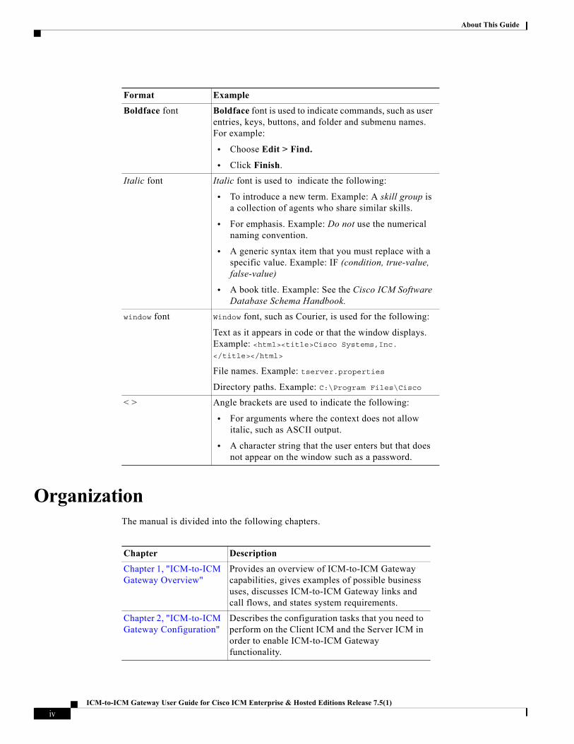
OrganizationThe manual is divided into the following chapters.
Format Example
Boldface font Boldface font is used to indicate commands, such as user entries, keys, buttons, and folder and submenu names. For example:
• Choose Edit > Find.
• Click Finish.
Italic font Italic font is used to indicate the following:
• To introduce a new term. Example: A skill group is a collection of agents who share similar skills.
• For emphasis. Example: Do not use the numerical naming convention.
• A generic syntax item that you must replace with a specific value. Example: IF (condition, true-value, false-value)
• A book title. Example: See the Cisco ICM Software Database Schema Handbook.
window font Window font, such as Courier, is used for the following:
Text as it appears in code or that the window displays. Example: <html><title>Cisco Systems,Inc. </title></html>
File names. Example: tserver.properties
Directory paths. Example: C:\Program Files\Cisco
< > Angle brackets are used to indicate the following:
• For arguments where the context does not allow italic, such as ASCII output.
• A character string that the user enters but that does not appear on the window such as a password.
Chapter Description
Chapter 1, "ICM-to-ICM Gateway Overview"
Provides an overview of ICM-to-ICM Gateway capabilities, gives examples of possible business uses, discusses ICM-to-ICM Gateway links and call flows, and states system requirements.
Chapter 2, "ICM-to-ICM Gateway Configuration"
Describes the configuration tasks that you need to perform on the Client ICM and the Server ICM in order to enable ICM-to-ICM Gateway functionality.
ivICM-to-ICM Gateway User Guide for Cisco ICM Enterprise & Hosted Editions Release 7.5(1)

About This GuideObtaining Documentation, Obtaining Support, and Security Guidelines
Obtaining Documentation, Obtaining Support, and Security Guidelines
For information on obtaining documentation, obtaining support, providing documentation feedback, security guidelines, and also recommended aliases and general Cisco documents, see the monthly What’s New in Cisco Product Documentation, which also lists all new and revised Cisco technical documentation, at:
http://www.cisco.com/en/US/docs/general/whatsnew/whatsnew.html
Subscribe to the What's New in Cisco Product Documentation as a Really Simple Syndication (RSS) feed and set content to be delivered directly to your desktop using a reader application. The RSS feeds are a free service and Cisco currently supports RSS version 2.0.
vICM-to-ICM Gateway User Guide for Cisco ICM Enterprise & Hosted Editions Release 7.5(1)

About This GuideObtaining Documentation, Obtaining Support, and Security Guidelines
viICM-to-ICM Gateway User Guide for Cisco ICM Enterprise & Hosted Editions Release 7.5(1)

ICM Administration Guide for Cisco ICM/IP
C H A P T E R 1
ICM-to-ICM Gateway OverviewThis chapter provides an overview of ICM-to-ICM Gateway. It discusses the following topics:
• Business uses for ICM-to-ICM Gateway
• The ICM-to-ICM Gateway link
• ICM-to-ICM Gateway call flows
• ICM-to-ICM Gateway fault tolerance capabilities
• ICM-to-ICM Gateway system and network configuration requirements
What is ICM-to-ICM Gateway?ICM-to-ICM Gateway extends the ICM software capability by allowing agents to simultaneously pre-route/post-route calls, and supply additional call-related information to a second agent on a different ICM. This enables the initial agent to pass on gathered information without the customer’s needing to repeat it to the second agent.
Following are some business scenarios where ICM-to-ICM Gateway functionality can be particularly useful.
• A customer calls the institutional department of a financial corporation for customer service assistance with a company-sponsored 401k. The customer then asks to be transferred to the retail department to obtain assistance with a personal account.
• Two corporations (for example, a bank and an insurance company), each of which has a contact center that uses an ICM, merge. It may often be desirable to transfer a call between the two companies; for example, to sell insurance to a bank customer.
• A customer calls a hotel to make a reservation. The hotel agent then asks the customer if he/she also needs to rent a car, and then transfers the customer to a car rental agent.
• A company uses an outsourcer to handle part of its overflow traffic. For example, the company service department handles paid support calls in-house but transfers warranty service requests to the outsourcer.
• A multi-national corporation encompasses several geographic regions; each geographic region has its own ICM.
In all these cases, ICM-to-ICM Gateway enables the call-related data to be transferred along with the call so the customer does not need to supply this information again.
1-1CC Enterprise & Hosted Editions Release 7.5(1)

Chapter 1 ICM-to-ICM Gateway OverviewICM-to-ICM Gateway Call Flow
ICM-to-ICM Gateway Call FlowFigure 1-1 illustrates basic ICM-to-ICM Gateway call flow.
Figure 1-1 Basic ICM-to-ICM Gateway Call Flow
1. A Client ICM receives a request. This could be a pre-route request from a service provider network (in which case the routing client is a NIC) or a post-route request from an ACD/IVR (in which case the PG acts as the routing client)
2. The Client ICM executes a script. At some point the script initiates a route request to the other ICM, referred to as the Server ICM. At this point the Server ICM must find a destination label for the call.
3. The Server ICM executes a script to select a destination label for the call. The Server ICM handles this call as a normal route request, save for the fact that the routing client is another ICM and not a service provider network or an ACD/IVR. Once a destination label is selected the Server ICM sends it back to the Client ICM.
4. When the Client ICM receives the destination label from the Server ICM, it passes the label directly to the routing client that initiated the route request. This does not happen under script control, but is an automatic process.
ICM-to-ICM CommunicationThe ICM-to-ICM Gateway link connects two ICMs through a Cisco proprietary protocol called INCRP (Intelligent Network Call Routing Protocol). Both ICMs have a component managing the connection.
The script node on the Client ICM is called an ICM Gateway. It sends the route requests and receives the responses (destination labels) from the Server ICM.
The component on the Server ICM is called an INCRP Network Interface Controller (INCRP NIC). The NIC receives route requests and sends responses back to the requester. An ICM can have an INCRP NIC, as well as other types of NICs.
Both the ICM Gateway and the INCRP NIC run on the Router machine, so no additional hardware is required.
1-2ICM Administration Guide for Cisco ICM/IPCC Enterprise & Hosted Editions Release 7.5(1)
Chapter 1 ICM-to-ICM Gateway OverviewICM-to-ICM Gateway Call Flow
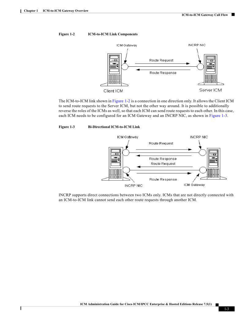
Figure 1-2 ICM-to-ICM Link Components
The ICM-to-ICM link shown in Figure 1-2 is a connection in one direction only. It allows the Client ICM to send route requests to the Server ICM, but not the other way around. It is possible to additionally reverse the roles of the ICMs as well, so that each ICM can send route requests to each other. In this case, each ICM needs to be configured for an ICM Gateway and an INCRP NIC, as shown in Figure 1-3.
Figure 1-3 Bi-Directional ICM-to-ICM Link
INCRP supports direct connections between two ICMs only. ICMs that are not directly connected with an ICM-to-ICM link cannot send each other route requests through another ICM.
1-3ICM Administration Guide for Cisco ICM/IPCC Enterprise & Hosted Editions Release 7.5(1)

Chapter 1 ICM-to-ICM Gateway OverviewICM-to-ICM Gateway Call Flow
Pre-RoutingFigure 1-4 illustrates a call flow scenario for a call that is pre-routed from one ICM to another.
Figure 1-4 Example Pre-Routing Call Flow
1. The Service Provider network sends a route request to the Client ICM.
2. The Client ICM receives the pre-route request and executes a routing script that determines that the route request is to be handed to another ICM. The ICM forwards the route request to the Server ICM.
3. The Server ICM executes a script that selects a peripheral target for the call and sends the corresponding label to the Client ICM.
4. If the selected target is reached using a translation route, the Server ICM sends the call context data to the selected peripheral, where it waits for the call to arrive. If translation routing is not used, this step is skipped.
5. The Client ICM forwards the destination label (that it received in Step 3) to the network.
6. The network connects the call to the selected destination on the Server ICM ACD/Agent.
7. If this was a translation routed call, the ACD connected to the Server ICM requests the call detail information from the PG where it has been waiting since Step 4 and sends the call to an agent.
1-4ICM Administration Guide for Cisco ICM/IPCC Enterprise & Hosted Editions Release 7.5(1)
Chapter 1 ICM-to-ICM Gateway OverviewICM-to-ICM Gateway Call Flow
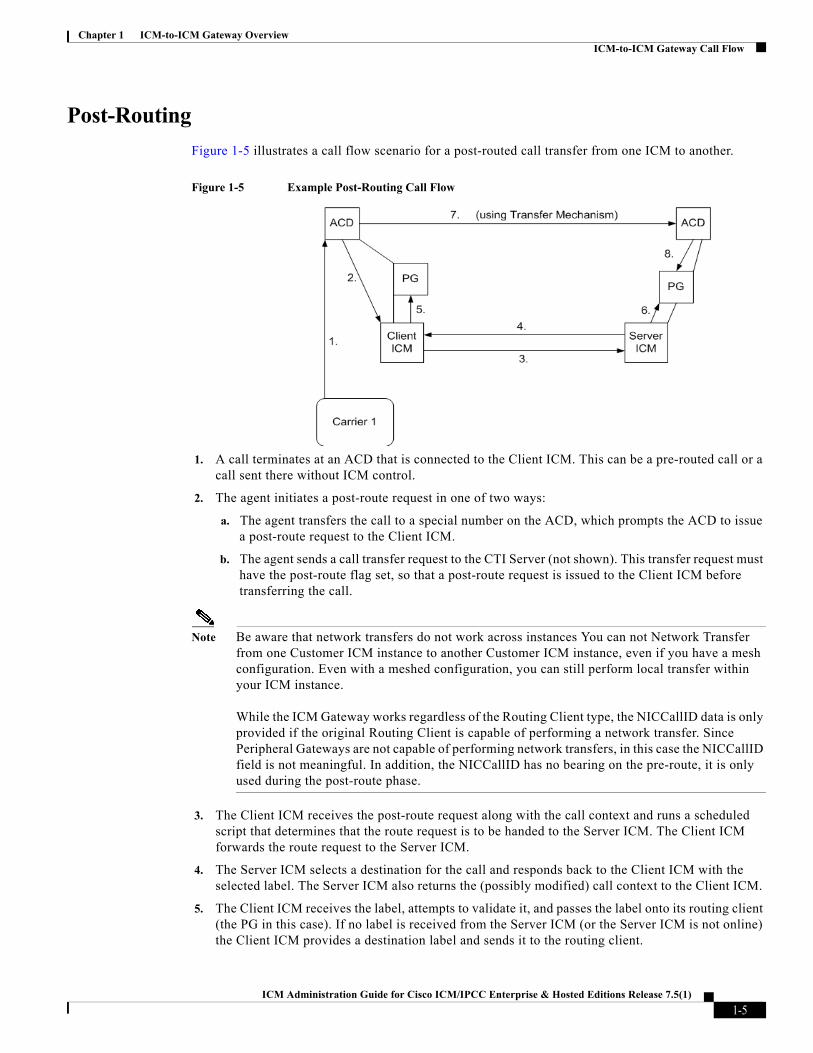
Post-RoutingFigure 1-5 illustrates a call flow scenario for a post-routed call transfer from one ICM to another.
Figure 1-5 Example Post-Routing Call Flow
1. A call terminates at an ACD that is connected to the Client ICM. This can be a pre-routed call or a call sent there without ICM control.
2. The agent initiates a post-route request in one of two ways:
a. The agent transfers the call to a special number on the ACD, which prompts the ACD to issue a post-route request to the Client ICM.
b. The agent sends a call transfer request to the CTI Server (not shown). This transfer request must have the post-route flag set, so that a post-route request is issued to the Client ICM before transferring the call.
Note Be aware that network transfers do not work across instances You can not Network Transfer from one Customer ICM instance to another Customer ICM instance, even if you have a mesh configuration. Even with a meshed configuration, you can still perform local transfer within your ICM instance. While the ICM Gateway works regardless of the Routing Client type, the NICCallID data is only provided if the original Routing Client is capable of performing a network transfer. Since Peripheral Gateways are not capable of performing network transfers, in this case the NICCallID field is not meaningful. In addition, the NICCallID has no bearing on the pre-route, it is only used during the post-route phase.
3. The Client ICM receives the post-route request along with the call context and runs a scheduled script that determines that the route request is to be handed to the Server ICM. The Client ICM forwards the route request to the Server ICM.
4. The Server ICM selects a destination for the call and responds back to the Client ICM with the selected label. The Server ICM also returns the (possibly modified) call context to the Client ICM.
5. The Client ICM receives the label, attempts to validate it, and passes the label onto its routing client (the PG in this case). If no label is received from the Server ICM (or the Server ICM is not online) the Client ICM provides a destination label and sends it to the routing client.
1-5ICM Administration Guide for Cisco ICM/IPCC Enterprise & Hosted Editions Release 7.5(1)

Chapter 1 ICM-to-ICM Gateway OverviewICM-to-ICM Gateway Call Flow
6. If the selected target was a peripheral target with an associated translation route, the Server ICM sends the translation route information to the PG, where the ACD waits until the call arrives at the ACD and the ACD retrieves the information from the PG (in Step 8). If the selected target does not use a translation route, this step is skipped. In that case, the call context is still transferred to the Server ICM but it is not available for the receiving ACD, since it cannot be matched with the call.
7. The original PG and the ACD transfer the call to its destination. The PG sends the destination label to the ACD. The ACD uses that information to disconnect the agent who requested the call transfer and connects the incoming call leg to its destination using a tie line or public network trunk.
8. If this is a translation route call, the ACD connected to the Server ICM receives the call, requests the call detail information from the PG (where it has been waiting since Step 6), and sends the call to an agent.
1-6ICM Administration Guide for Cisco ICM/IPCC Enterprise & Hosted Editions Release 7.5(1)

Chapter 1 ICM-to-ICM Gateway OverviewLogical Connection Management and Fault Tolerance
Logical Connection Management and Fault ToleranceBecause the ICM software is typically deployed as a synchronous duplex pair, the ICM-to-ICM Gateway is likewise deployed between ICM system pairs. This leverages the ICM software’s fault tolerant architecture and keeps the synchronous router pairs in sync.
ICM-to-ICM Gateway addresses the following other possible points of failure as follows:
• In the case of a link failure, each INCRP NIC has a link to both ICM Gateway components. Each INCRP NIC can therefore maintain communications with the other ICM Gateway.
• If an INCRP NIC fails, the Client ICM’s routers are synchronized and can communicate via the remaining INCRP NIC.
1-7ICM Administration Guide for Cisco ICM/IPCC Enterprise & Hosted Editions Release 7.5(1)

Chapter 1 ICM-to-ICM Gateway OverviewLogical Connection Management and Fault Tolerance
Note If a link failure or a NIC failure occurs, calls that were in progress at the time of the failure may be lost.
• If an ICM-to-ICM Gateway fails, the Server ICM’s routers are synchronized and can communicate via the remaining ICM-to-ICM Gateway.
Note For a more complete discussion of ICM Fault Tolerance, refer to the ICM Administration Guide for Cisco ICM Enterprise Edition.
1-8ICM Administration Guide for Cisco ICM/IPCC Enterprise & Hosted Editions Release 7.5(1)
Chapter 1 ICM-to-ICM Gateway OverviewICM-to-ICM Gateway Requirements
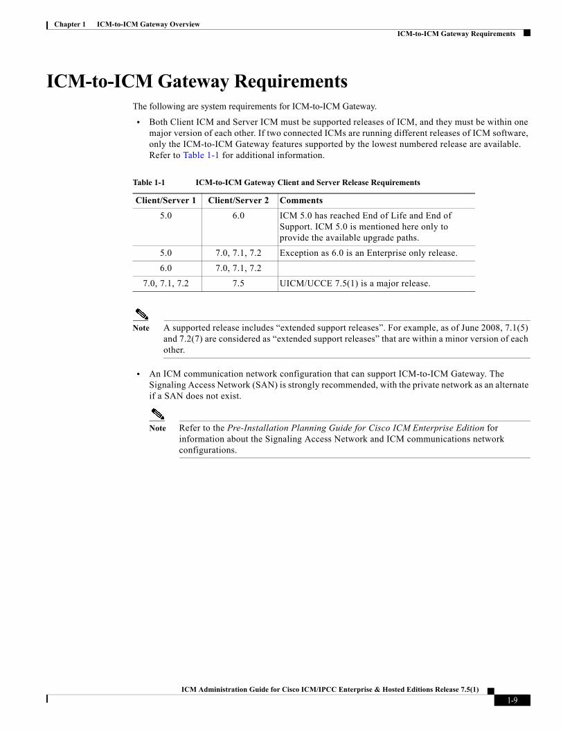
ICM-to-ICM Gateway RequirementsThe following are system requirements for ICM-to-ICM Gateway.
• Both Client ICM and Server ICM must be supported releases of ICM, and they must be within one major version of each other. If two connected ICMs are running different releases of ICM software, only the ICM-to-ICM Gateway features supported by the lowest numbered release are available. Refer to Table 1-1 for additional information.
Note A supported release includes “extended support releases”. For example, as of June 2008, 7.1(5) and 7.2(7) are considered as “extended support releases” that are within a minor version of each other.
• An ICM communication network configuration that can support ICM-to-ICM Gateway. The Signaling Access Network (SAN) is strongly recommended, with the private network as an alternate if a SAN does not exist.
Note Refer to the Pre-Installation Planning Guide for Cisco ICM Enterprise Edition for information about the Signaling Access Network and ICM communications network configurations.
Table 1-1 ICM-to-ICM Gateway Client and Server Release Requirements
Client/Server 1 Client/Server 2 Comments
5.0 6.0 ICM 5.0 has reached End of Life and End of Support. ICM 5.0 is mentioned here only to provide the available upgrade paths.
5.0 7.0, 7.1, 7.2 Exception as 6.0 is an Enterprise only release.
6.0 7.0, 7.1, 7.2
7.0, 7.1, 7.2 7.5 UICM/UCCE 7.5(1) is a major release.
1-9ICM Administration Guide for Cisco ICM/IPCC Enterprise & Hosted Editions Release 7.5(1)

Chapter 1 ICM-to-ICM Gateway OverviewICM-to-ICM Gateway Requirements
1-10ICM Administration Guide for Cisco ICM/IPCC Enterprise & Hosted Editions Release 7.5(1)

ICM Administration Guide for Cisco ICM/IP
C H A P T E R 2
ICM-to-ICM Gateway ConfigurationThis chapter includes instructions for the various tasks that you need to perform on the client and server systems in order for ICM-to-ICM Gateway to function correctly.
For the Client ICM, these tasks include the following:
• Configuring an ICM Gateway process on the Router.
• Making the necessary script changes for sending pre-route or post-route requests to the Server ICM.
• Optionally, specifying a fixed local port number for the Network CIC process.
For the Server ICM, these tasks include the following:
• Installing and Configuring an INCRP NIC on the Router.
• Setting up the necessary translation route labels.
• Making the necessary script changes for returning calls and labels to the Client ICM.
Note If you are implementing a bidirectional ICM-to-ICM Gateway link (see Chapter 1, “ICM-to-ICM Gateway Overview”), you need to perform Client and Server tasks on both ICM systems.
Client ICM ConfigurationThis section provides instructions for the configuration tasks you need to perform on the Client ICM.
Identify the Client for the ServerTo identify the ICM Gateway Client for the ICM Gateway Server, run a full ICM Setup on the Client Router machine.
Note For more information on router installation, refer to the ICM Installation Guide for Cisco ICM/IPCC Enterprise & Hosted Editions.
For each ICM-to-ICM Gateway client, perform the following steps.
Step 1 In the Router Properties screen, check the Remote Network Routing option box
Step 2 Use the NAM ID field to specify a Client ICM ID number.
2-1CC Enterprise & Hosted Editions Release 7.5(1)
Chapter 2 ICM-to-ICM Gateway ConfigurationDefining Client ICM Configuration Data
• If the associated Server ICM will be communicating with only one Client ICM, you can accept the default NAM ID field value of 0.
• If the associated Server ICM will be communicating with multiple Client ICMs, the NAM ID value:
– Needs to be a unique number for each Client ICM in the configuration.
– Must be non-zero; start with the number 1.
Note Make a note of this Client ICM ID number and use the same number for the Client ID setting in the Server ICM configuration.
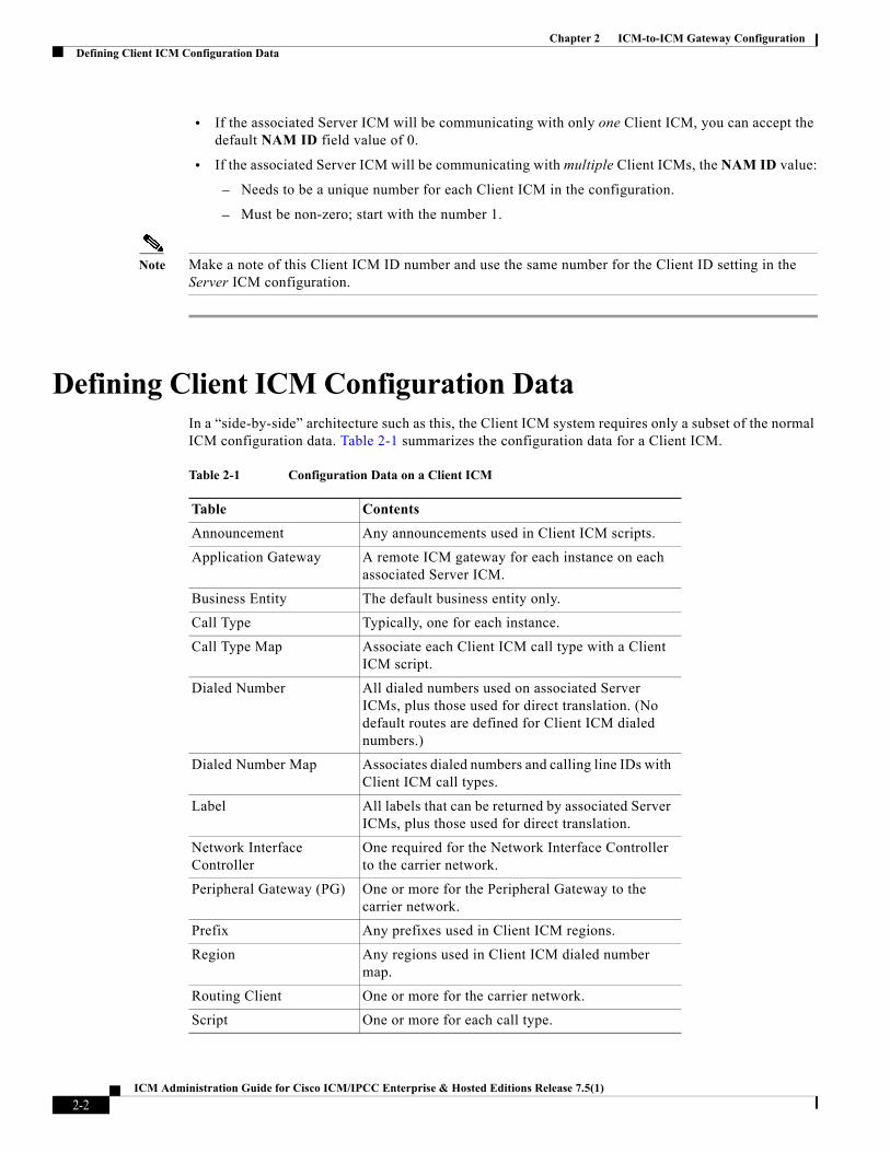
Defining Client ICM Configuration DataIn a “side-by-side” architecture such as this, the Client ICM system requires only a subset of the normal ICM configuration data. Table 2-1 summarizes the configuration data for a Client ICM.
Table 2-1 Configuration Data on a Client ICM
Table Contents
Announcement Any announcements used in Client ICM scripts.
Application Gateway A remote ICM gateway for each instance on each associated Server ICM.
Business Entity The default business entity only.
Call Type Typically, one for each instance.
Call Type Map Associate each Client ICM call type with a Client ICM script.
Dialed Number All dialed numbers used on associated Server ICMs, plus those used for direct translation. (No default routes are defined for Client ICM dialed numbers.)
Dialed Number Map Associates dialed numbers and calling line IDs with Client ICM call types.
Label All labels that can be returned by associated Server ICMs, plus those used for direct translation.
Network Interface Controller
One required for the Network Interface Controller to the carrier network.
Peripheral Gateway (PG) One or more for the Peripheral Gateway to the carrier network.
Prefix Any prefixes used in Client ICM regions.
Region Any regions used in Client ICM dialed number map.
Routing Client One or more for the carrier network.
Script One or more for each call type.
2-2ICM Administration Guide for Cisco ICM/IPCC Enterprise & Hosted Editions Release 7.5(1)

Chapter 2 ICM-to-ICM Gateway ConfigurationDefining Client ICM Configuration Data
The Client ICM needs only a limited configuration (dialed numbers, labels, basic routing scripts, etc.) while the instance-specific scripts, configuration, real-time, and historical data are stored on the Server ICM.
To set up your Client ICM configuration, run Configuration Manager on a Client ICM Admin Workstation.
Note For instructions on using Configuration Manager, refer to the ICM Configuration Guide for Cisco ICM Enterprise Edition.
Create or Configure the Gateway Process on the Client System RouterAn Application Gateway process must be configured on the Client ICM for each Server ICM that the Client ICM is going to communicate with.
Configuring a New Gateway
If you need to configure a new Application Gateway, perform the following steps.
Step 1 From the ICM Configuration Manager on an Admin Workstation associated with the Client ICM, select Calls > Application Gateway > Application Gateway List. The Application Gateway List window appears.
Step 2 Click Retrieve.
Step 3 Click Add. The Attributes tab appears.
2-3ICM Administration Guide for Cisco ICM/IPCC Enterprise & Hosted Editions Release 7.5(1)

Chapter 2 ICM-to-ICM Gateway ConfigurationDefining Client ICM Configuration Data
Step 4 Specify the following values on the Attributes tab:
• Name. Enter a name for the ICM Gateway.
• Type. Choose Remote ICM.
• Preferred Side. Indicates the preferred side of the Gateway to use when both are available. If only one side is available, ICM software uses that side regardless of preference.
• Encryption. Indicates whether requests to the Application Gateway are encrypted. Choose None.
• Fault Tolerance. If the Application Gateway is duplexed, specifies the fault-tolerance strategy it uses. Choose None.
• Connection. Choose whether the Gateway is Duplex (has both a Side and Side B connection), Simplex A (only has a Side A), or Simplex B (only has a Side B).
• Description. (Optional.) Additional information about the gateway.
Step 5 Click the Save button to create the gateway.
Note Make a note of the Application Gateway ID value, as you will need it when you run Setup to configure the INCRP NIC on the Server ICM.
Step 6 To set the connection information, click on the Connection Side A tab or the Connection Side B tab.
Step 7 To specify an address, click on the Enter Address button. The Enter NAM Addresses dialog box appears.
2-4ICM Administration Guide for Cisco ICM/IPCC Enterprise & Hosted Editions Release 7.5(1)

Chapter 2 ICM-to-ICM Gateway ConfigurationDefining Client ICM Configuration Data
Step 8 Specify the following information:
• NAM Mode. Select Single NAM.
• IP Address/Name. Enter the high priority IP address of the Server ICM. (Normally this is the public IP address, but if no public address is available, use the high priority private IP address.) This address must be the same address specified for the INCRP NIC on the targeted system. (You may use the hostname in place of the address.)
• Instance Number. Enter the Instance Number of the Server ICM (0 through 24).
• Side. Indicate which side of the Client ICM prefers this connection:
– Side A. Client ICM Side A prefers to use this connection.
– Side B. Client ICM Side B prefers to use this connection.
– None. Neither side of the Client ICM prefers to use this connection.
– Both Side A and B. Both sides of the Client ICM prefer to use this connection.
Note Consider network traffic in choosing this value. For example, if one side of the Client ICM is co-located with only one side of the Server ICM, you can make that the preferred connection in order to avoid unnecessary WAN traffic to the other side.
Step 9 When finished, click Save to save the changes.
Step 10 From the Application Gateway list, make note of the Application Gateway IDs number(s) for the server system(s). You will need to specify these Application Gateway ID number(s) during Server side configuration.
2-5ICM Administration Guide for Cisco ICM/IPCC Enterprise & Hosted Editions Release 7.5(1)

Chapter 2 ICM-to-ICM Gateway ConfigurationDefining Client ICM Configuration Data
The bottom half of the ConnectionSide A and Connection Side B tabs display a number of timeout and limit values. Accept the defaults for these values.
Configuring an Existing Gateway
If the gateway process is already present on the Router, perform the following steps to configure it for ICM-to-ICM Gateway use.
Step 1 Bring up the Calls > Application Gateway > Application Gateway List screen.
Step 2 Click Retrieve.
Step 3 From the Application Gateway list, make note of the Application Gateway IDs number(s) for the server system(s). You will need to specify these Application Gateway ID number(s) during Server side configuration.
Step 4 Configure the Connection Side A and Connection Side B tabs as needed.
Note Refer to the ICM Scripting and Media Routing Guide for Cisco ICM/IPCC Enterprise & Hosted Editions for instructions.
Step 5 Bring up the Enterprise > System Information Screen.
2-6ICM Administration Guide for Cisco ICM/IPCC Enterprise & Hosted Editions Release 7.5(1)
Chapter 2 ICM-to-ICM Gateway ConfigurationDefining Client ICM Configuration Data
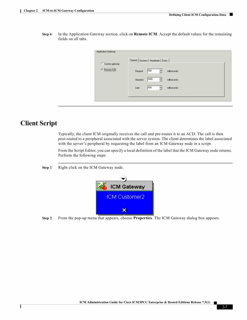
Step 6 In the Application Gateway section, click on Remote ICM. Accept the default values for the remaining fields on all tabs.
Client ScriptTypically, the client ICM originally receives the call and pre-routes it to an ACD. The call is then post-routed to a peripheral associated with the server system. The client determines the label associated with the server’s peripheral by requesting the label from an ICM Gateway node in a script.
From the Script Editor, you can specify a local definition of the label that the ICM Gateway node returns. Perform the following steps:
Step 1 Right click on the ICM Gateway node.
Step 2 From the pop-up menu that appears, choose Properties. The ICM Gateway dialog box appears.
2-7ICM Administration Guide for Cisco ICM/IPCC Enterprise & Hosted Editions Release 7.5(1)
Chapter 2 ICM-to-ICM Gateway ConfigurationDefining Client ICM Configuration Data
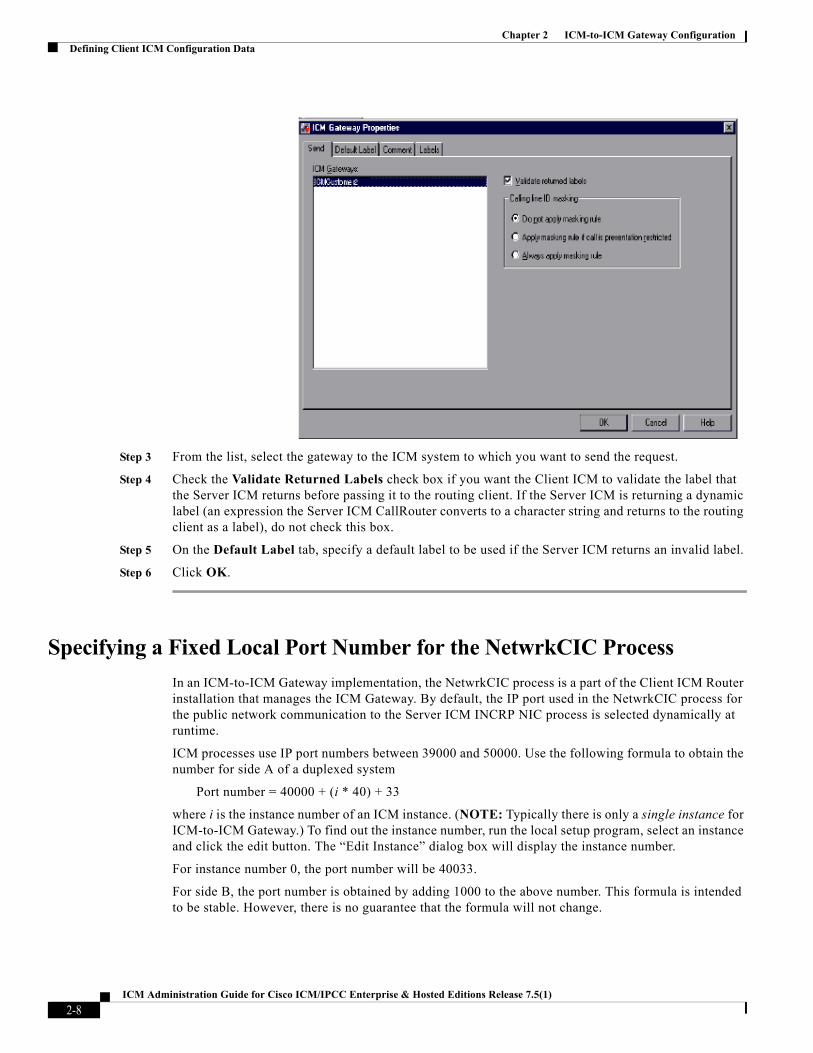
Step 3 From the list, select the gateway to the ICM system to which you want to send the request.
Step 4 Check the Validate Returned Labels check box if you want the Client ICM to validate the label that the Server ICM returns before passing it to the routing client. If the Server ICM is returning a dynamic label (an expression the Server ICM CallRouter converts to a character string and returns to the routing client as a label), do not check this box.
Step 5 On the Default Label tab, specify a default label to be used if the Server ICM returns an invalid label.
Step 6 Click OK.
Specifying a Fixed Local Port Number for the NetwrkCIC ProcessIn an ICM-to-ICM Gateway implementation, the NetwrkCIC process is a part of the Client ICM Router installation that manages the ICM Gateway. By default, the IP port used in the NetwrkCIC process for the public network communication to the Server ICM INCRP NIC process is selected dynamically at runtime.
ICM processes use IP port numbers between 39000 and 50000. Use the following formula to obtain the number for side A of a duplexed system
Port number = 40000 + (i * 40) + 33
where i is the instance number of an ICM instance. (NOTE: Typically there is only a single instance for ICM-to-ICM Gateway.) To find out the instance number, run the local setup program, select an instance and click the edit button. The “Edit Instance” dialog box will display the instance number.
For instance number 0, the port number will be 40033.
For side B, the port number is obtained by adding 1000 to the above number. This formula is intended to be stable. However, there is no guarantee that the formula will not change.
2-8ICM Administration Guide for Cisco ICM/IPCC Enterprise & Hosted Editions Release 7.5(1)

Chapter 2 ICM-to-ICM Gateway ConfigurationServer Configuration
This dynamic port allocation is an issue for some ICM customers. You can optionally modify the NetwrkCIC process to use a specific port number. If a specific port number is provided in the registry of the Client ICM machine, the NetwrkCIC process will instead bind to that port number when communicating with the server INCRP NIC process.
To specify this port number, add the following registry entry on the Client ICM machine:HKEY_LOCAL_MACHINE\SOFTWARE\Cisco Systems, Inc.\ICM\<instance name>\Router[A,B]\CIC\CurrentVersion\Configuration\CIC Public LAN IP Port
Specify this entry as a DWORD type.
This registry entry is not managed by the ICM Setup program. Therefore if you upgrade ICM software later, you must add the registry entry again.
If the registry entry is not present, the NetwrkCIC process uses the port dynamically allocated as usual.
If you change the port number while the NetwrkCIC process is running, you must restart the ICM router service for it to take effect.
Server ConfigurationThis section provides instructions for the configuration tasks you need to perform on the Server ICM.
Defining and Configuring the INCRP NICTo set up the INCRP NIC for each instance on the Server ICM, you must perform the following tasks:
• Install the INCRP NIC, if you have not already done so
• Define the INCRP NIC using the NIC Explorer tool
• Add INCRP NIC information using ICM Setup
Installing the INCRP NIC
If you need to install the INCRP NIC, refer to the ICM Installation Guide for Cisco ICM/IPCC Enterprise & Hosted Editions for guidelines and procedures.
How to Define the INCRP NIC
Step 1 Within the ICM Admin Workstation group, double-click AW Select. The Select ICM AW Service window appears.
Step 2 Select the instance you will be configuring.
Step 3 From the ICM Configuration Manager, invoke the NIC Explorer tool. The NIC Explorer window appears.
Step 4 In the Select filter data box, click Retrieve. This enables the Add NIC button.
Step 5 Click Add NIC. A new NIC and its routing client display in the tree window. Next to each is a To Be Inserted icon.
On the right of the tree window, tabbed fields also display the new NIC’s and routing client’s configuration information.
2-9ICM Administration Guide for Cisco ICM/IPCC Enterprise & Hosted Editions Release 7.5(1)
Chapter 2 ICM-to-ICM Gateway ConfigurationServer Configuration
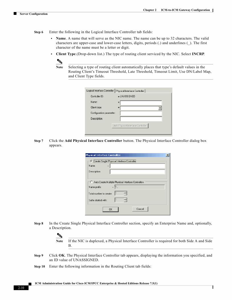
Step 6 Enter the following in the Logical Interface Controller tab fields:
• Name. A name that will serve as the NIC name. The name can be up to 32 characters. The valid characters are upper-case and lower-case letters, digits, periods (.) and underlines (_). The first character of the name must be a letter or digit.
• Client Type.(Drop-down list.) The type of routing client serviced by the NIC. Select INCRP.
Note Selecting a type of routing client automatically places that type’s default values in the Routing Client’s Timeout Threshold, Late Threshold, Timeout Limit, Use DN/Label Map, and Client Type fields.
Step 7 Click the Add Physical Interface Controller button. The Physical Interface Controller dialog box appears.
Step 8 In the Create Single Physical Interface Controller section, specify an Enterprise Name and, optionally, a Description.
Note If the NIC is duplexed, a Physical Interface Controller is required for both Side A and Side B.
Step 9 Click OK. The Physical Interface Controller tab appears, displaying the information you specified, and an ID value of UNASSIGNED.
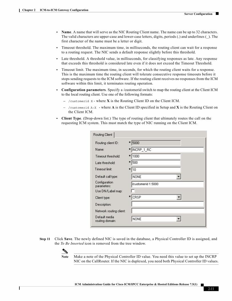
Step 10 Enter the following information in the Routing Client tab fields:
2-10ICM Administration Guide for Cisco ICM/IPCC Enterprise & Hosted Editions Release 7.5(1)
Chapter 2 ICM-to-ICM Gateway ConfigurationServer Configuration
• Name. A name that will serve as the NIC Routing Client name. The name can be up to 32 characters. The valid characters are upper-case and lower-case letters, digits, periods (.) and underlines (_). The first character of the name must be a letter or digit.
• Timeout threshold. The maximum time, in milliseconds, the routing client can wait for a response to a routing request. The NIC sends a default response slightly before this threshold.
• Late threshold. A threshold value, in milliseconds, for classifying responses as late. Any response that exceeds this threshold is considered late even if it does not exceed the Timeout Threshold.
• Timeout limit. The maximum time, in seconds, for which the routing client waits for a response. This is the maximum time the routing client will tolerate consecutive response timeouts before it stops sending requests to the ICM software. If the routing client receives no responses from the ICM software within this limit, it terminates routing operation.
• Configuration parameters. Specify a /customerid switch to map the routing client at the Client ICM to the local routing client. Use one of the following formats:
– /customerid X - where X is the Routing Client ID on the Client ICM.
– /customerid A:X - where A is the Client ID specified in Setup and X is the Routing Client on the Client ICM.
• Client Type. (Drop-down list.) The type of routing client that ultimately routes the call on the requesting ICM system. This must match the type of NIC running on the Client ICM.
Step 11 Click Save. The newly defined NIC is saved in the database, a Physical Controller ID is assigned, and the To Be Inserted icon is removed from the tree window.
Note Make a note of the Physical Controller ID value. You need this value to set up the INCRP NIC on the CallRouter. If the NIC is duplexed, you need both Physical Controller ID values.
2-11ICM Administration Guide for Cisco ICM/IPCC Enterprise & Hosted Editions Release 7.5(1)
Chapter 2 ICM-to-ICM Gateway ConfigurationServer Configuration
Step 12 Click Close to exit the NIC Explorer.
Configuring the INCRP NIC in ICM Setup
To configure the INCRP NIC on the Server ICM, run ICM Setup and edit the Router from the Server Router machine (rather than from the installation CD).
Note For more information on router installation, refer to the ICM Installation Guide for Cisco ICM/IPCC Enterprise & Hosted Editions.
Perform the following steps.
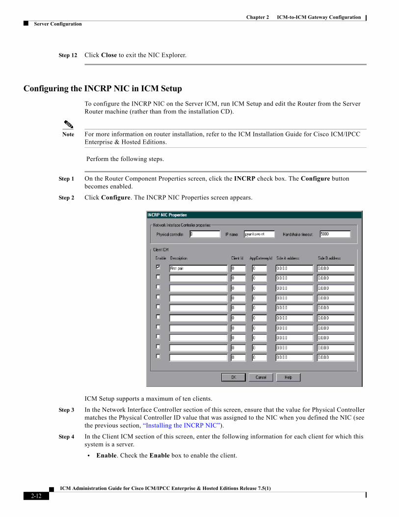
Step 1 On the Router Component Properties screen, click the INCRP check box. The Configure button becomes enabled.
Step 2 Click Configure. The INCRP NIC Properties screen appears.
ICM Setup supports a maximum of ten clients.
Step 3 In the Network Interface Controller section of this screen, ensure that the value for Physical Controller matches the Physical Controller ID value that was assigned to the NIC when you defined the NIC (see the previous section, “Installing the INCRP NIC”).
Step 4 In the Client ICM section of this screen, enter the following information for each client for which this system is a server.
• Enable. Check the Enable box to enable the client.
2-12ICM Administration Guide for Cisco ICM/IPCC Enterprise & Hosted Editions Release 7.5(1)

Chapter 2 ICM-to-ICM Gateway ConfigurationServer Configuration
• Description. Enter a description of the client (optional).
• Client ID. Enter the same value that you entered in the NAM ID field on the Router Properties screen during client machine router setup (see the “Identify the Client for the Server” section on page 2-1).
• Application Gateway ID. Enter the application gateway ID. This must match the application gateway ID as shown on the Calls > Application Gateway All list screen (see the “Create or Configure the Gateway Process on the Client System Router” section on page 2-3).
• Side A Address, Side B Address. If you are using the Signaling Access Network, enter the Signaling Access Network IP address for the client. Otherwise, enter the Public Network IP address.
Step 5 Click OK.
Setting Up Translation Route LabelsFrom the ICM-to-ICM Gateway server’s point of view it is doing a translation route to one of its peripheral targets. When you set up a translation route on the Server ICM, you must set up a label for the original routing client for a call to access each of the peripheral targets associated with the translation route. For example, if the routing client is an interexchange carrier (IXC), you must set up a label to the targets with the IXC. This allows the call to be initially sent to the translation route at the peripheral.
Note For instructions on how to run Translation Route Wizard and how to define translation route labels, refer to the ICM Configuration Guide for Cisco ICM Enterprise Edition.
Modifying Routing ScriptsThe server will require a script that handles requests from the client. The script is associated with a call type, which is in turn defined by the dialed number, calling line id, and caller entered digits.
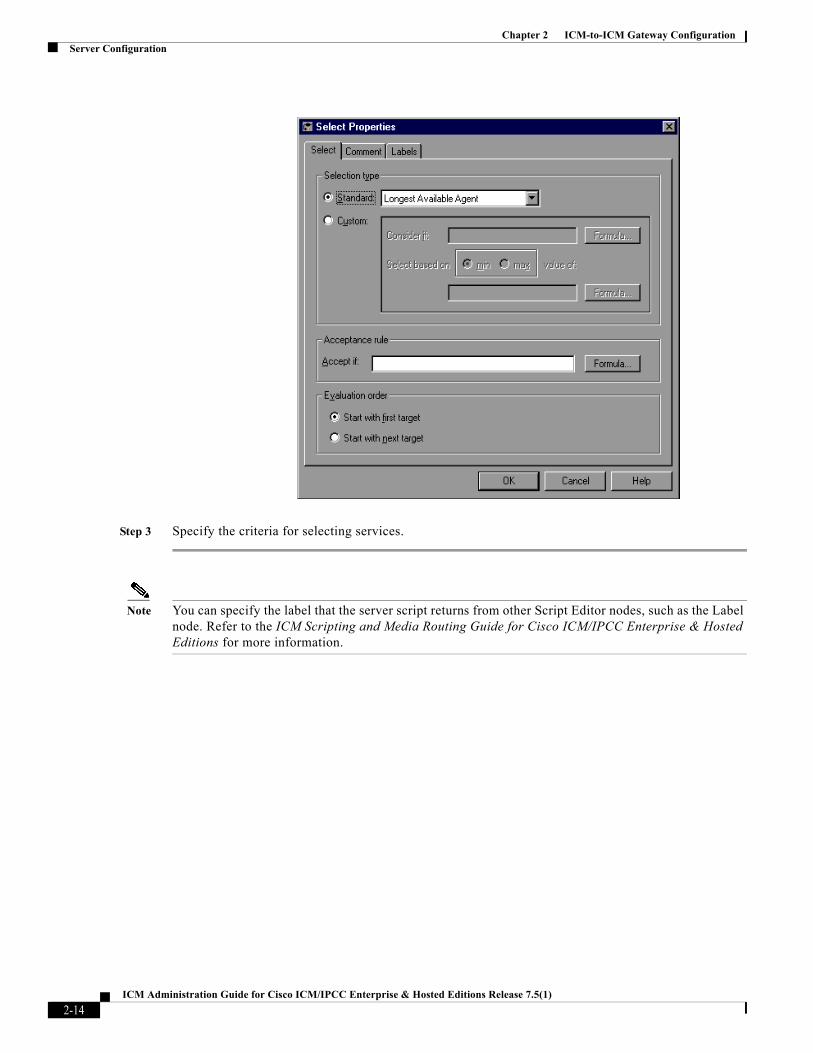
From the Script Editor, you can specify the label that the server script returns to the client. For example, you could create a Select node that routes calls to specified services under certain conditions. Perform the following steps.
Step 1 From Script Editor, connect the Select node to a Service node.
Step 2 Right click on the Select node and choose Properties. The dialog box appears.
2-13ICM Administration Guide for Cisco ICM/IPCC Enterprise & Hosted Editions Release 7.5(1)
Chapter 2 ICM-to-ICM Gateway ConfigurationServer Configuration
Step 3 Specify the criteria for selecting services.
Note You can specify the label that the server script returns from other Script Editor nodes, such as the Label node. Refer to the ICM Scripting and Media Routing Guide for Cisco ICM/IPCC Enterprise & Hosted Editions for more information.
2-14ICM Administration Guide for Cisco ICM/IPCC Enterprise & Hosted Editions Release 7.5(1)

ICM-to-ICM Gateway User Guide for Cisco I
I N D E X
B
Basic call flow 1-2
C
Client ICM
configuring 2-1
Router setup 2-1
script 2-7
D
defining
NIC 2-9
F
Fault tolerance 1-6
I
ICM Client
mapping Routing Clients 2-11
ICM Gateway node 2-7
ICM Gateway process 1-2
ICM-to-ICM Gateway
basic call flow 1-2
business uses 1-1
post-routing call flow 1-5
pre-routing call flow 1-4
system requirements 1-8
ICM-to-ICM link 1-2
INCRP NIC 1-2
Intelligent Network Call Routing Protocol (INCRP) 1-2
M
Mapping Client ICM and local Routing Clients 2-11
N
NAM
configuration data 2-2
Network Interface Controller (NIC)
defining 2-9
NIC
defining 2-9
P
Physical controller ID
INCRP NIC 2-10
Post-routing call flow 1-5
Pre-routing call flow 1-4
R
Router setup
Client ICM 2-1, 2-12
Routing Clients, mapping 2-11
S
Scripts
Client ICM 2-7
IN-1CM Enterprise & Hosted Editions Release 7.5(1)

Index
Server ICM 2-13
Server ICM
configuring 2-9
script 2-13
Signaling Access Network (SAN) 1-8
System requirements 1-8
IN-2ICM-to-ICM Gateway User Guide for Cisco ICM Enterprise &
Hosted Editions Release 7.5(1)