Hit U – 3G modem preliminary datasheet · - Downlink coding schemes – CS 1-4, MCS 1-9 ... The...
25
rev1.1 may 2012 Hit U – 3G modem preliminary datasheet
Transcript of Hit U – 3G modem preliminary datasheet · - Downlink coding schemes – CS 1-4, MCS 1-9 ... The...
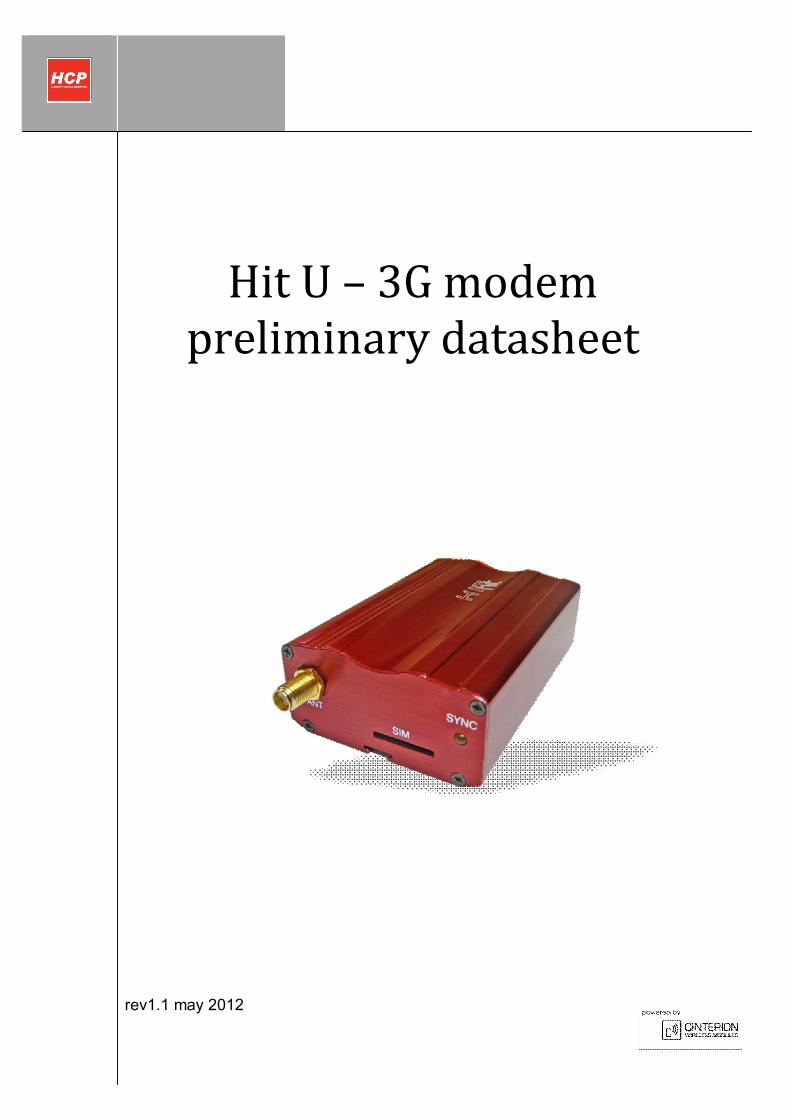
rev1.1 may 2012
Hit U – 3G modem preliminary datasheet
HIT U - 3G
Page 2 of 25
Copyright Transmittal, reproduction, dissemination and/or editing of this document as well as utilization of its contents and communication thereof to others without express authorization are prohibited. Offenders will be held liable for payment of damages. All rights created by patent grant or registration of a utility model or design patent are reserved. Copyright © 2012, HCP d.o.o Trademark notice Cinterion is registered trademark of ©Cinterion Wireless Modules GmbH in the Germany and/or other countries. All other registered trademarks or trademarks mentioned in this document are property of their respective owners.
HIT U - 3G
Page 3 of 25
Contents 1. Introduction .................................................................................................................................4
1.1 Related documents ............................................................................................................................. 4
1.2 Terms and Abbreviations ................................................................................................................... 5
1.3 Safety Precautions .............................................................................................................................. 7
2. Product Concept ...........................................................................................................................8
2.1 Key Features of HIT U 3G Terminal .................................................................................................. 8
3. Interface Description ...............................................................................................................10
3.1 Overview .............................................................................................................................................. 10
3.2 Block Diagram .................................................................................................................................... 11
3.3 Operating Modes of HIT U 3G terminal .......................................................................................... 12
3.4 Power Supply .................................................................................................................................... 13
3.4.1 Turn HIT U terminal on .................................................................................................................. 14
3.4.2 Reset HIT U terminal ...................................................................................................................... 14
3.4.3 Turn off HIT U terminal .................................................................................................................. 14 3.4.4 Disconnecting power supply ........................................................................................................................ 14 3.4.5 Automatic thermal shutdown........................................................................................................................ 15
3.5 USB Interface..................................................................................................................................... 16
3.6 SIM interface ...................................................................................................................................... 17
3.7 Status LED ......................................................................................................................................... 18
3.8 Antenna interface ............................................................................................................................. 19
4. Electrical and Environmental Characteristics....................................................................20
4.1 Apsolute Maximum Ratings ............................................................................................................. 20
4.2 Recommended Operating conditions ............................................................................................ 20
4.4 Storage Conditions ........................................................................................................................... 21
4.5 Electrical Specifications of the Application Interface ................................................................ 22 4.5.1 USB interface ............................................................................................................................................... 22 4.5.2 Antenna interface .......................................................................................................................................... 22
5. Mechanical Characteristics ....................................................................................................23
6. List of Parts and Accessories ...............................................................................................24
HIT U - 3G
Page 4 of 25
1. Introduction This document describes the hardware of HCP HIT U – USB 3G modem, with interface specifications, electrical and mechanical characteristics.
1.1 Related documents
[1] HC25 AT command set [2] HC25 Hardware interface description

HIT U - 3G
Page 5 of 25
1.2 Terms and Abbreviations Abbreviation Description ADC Analog-to-Digital Converter ARP Antenna Reference Point ASIC Application Specific Integrated Circuit ATC AT Cellular BTS Base Transceiver Station CB Cell Broadcast CODEC Coder-Decoder CPU Central Processing Unit DCE Data Circuit terminating Equipment DSP Digital Signal Processor DSR Data Set Ready DTR Data Terminal Ready EFR Enhanced Full Rate EGSM Enhanced GSM EMC Electromagnetic Compatibility ESD Electrostatic Discharge ETS European Telecommunication Standard FDMA Frequency Division Multiple Access FR Full rate G.C.F. GSM Conformity Forum GSM Global Standard for Mobile Communication HF Hands-free HR Half rate HW Hardware IC Integrated Circuit IF Intermediate Frequency IMEI International Mobile Equipment Identifier I/O Input/ Output IGT Ignition ISO International Standards Organization ITU International Telecommunications Union kbps kbits per second Li-Ion Lithium-Ion LVD Low voltage Directive Mbps Mbits per second MMI Machine Machine Interface MO Mobile Originated MS Mobile Station MT Mobile Terminated NC Not Connected NTC Negative Temperature Coefficient PA Power Amplifier PCB Printed Circuit Board PCM Pulse Code Modulation PCS Personal Communication System
HIT U - 3G
Page 6 of 25
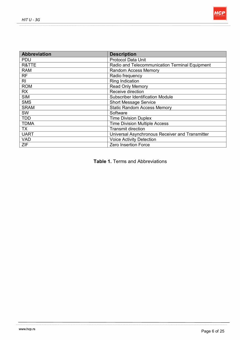
Abbreviation Description PDU Protocol Data Unit R&TTE Radio and Telecommunication Terminal Equipment RAM Random Access Memory RF Radio frequency RI Ring Indication ROM Read Only Memory RX Receive direction SIM Subscriber Identification Module SMS Short Message Service SRAM Static Random Access Memory SW Software TDD Time Division Duplex TDMA Time Division Multiple Access TX Transmit direction UART Universal Asynchronous Receiver and Transmitter VAD Voice Activity Detection ZIF Zero Insertion Force
Table 1. Terms and Abbreviations
HIT U - 3G
Page 7 of 25
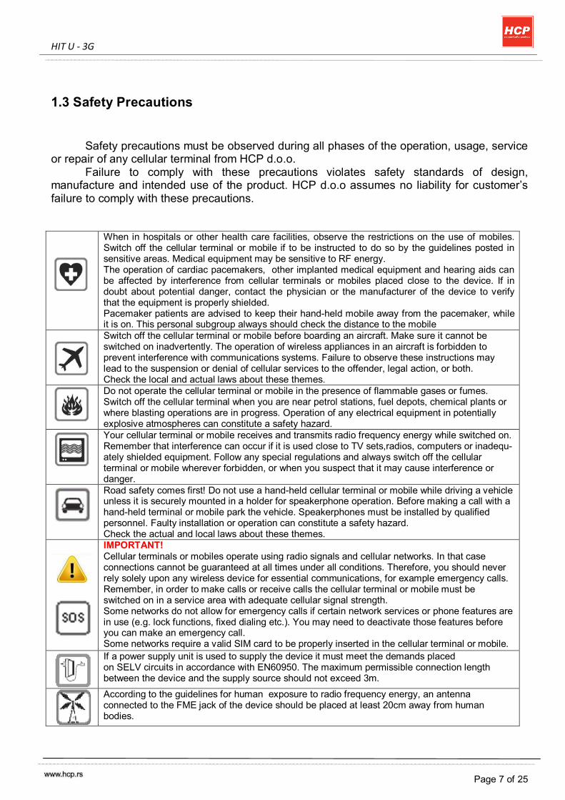
1.3 Safety Precautions
Safety precautions must be observed during all phases of the operation, usage, service or repair of any cellular terminal from HCP d.o.o.
Failure to comply with these precautions violates safety standards of design, manufacture and intended use of the product. HCP d.o.o assumes no liability for customer’s failure to comply with these precautions.
When in hospitals or other health care facilities, observe the restrictions on the use of mobiles. Switch off the cellular terminal or mobile if to be instructed to do so by the guidelines posted in sensitive areas. Medical equipment may be sensitive to RF energy. The operation of cardiac pacemakers, other implanted medical equipment and hearing aids can be affected by interference from cellular terminals or mobiles placed close to the device. If in doubt about potential danger, contact the physician or the manufacturer of the device to verify that the equipment is properly shielded. Pacemaker patients are advised to keep their hand-held mobile away from the pacemaker, while it is on. This personal subgroup always should check the distance to the mobile
Switch off the cellular terminal or mobile before boarding an aircraft. Make sure it cannot be switched on inadvertently. The operation of wireless appliances in an aircraft is forbidden to prevent interference with communications systems. Failure to observe these instructions may lead to the suspension or denial of cellular services to the offender, legal action, or both. Check the local and actual laws about these themes.
Do not operate the cellular terminal or mobile in the presence of flammable gases or fumes. Switch off the cellular terminal when you are near petrol stations, fuel depots, chemical plants or where blasting operations are in progress. Operation of any electrical equipment in potentially explosive atmospheres can constitute a safety hazard.
Your cellular terminal or mobile receives and transmits radio frequency energy while switched on. Remember that interference can occur if it is used close to TV sets,radios, computers or inadequ- ately shielded equipment. Follow any special regulations and always switch off the cellular terminal or mobile wherever forbidden, or when you suspect that it may cause interference or danger.
Road safety comes first! Do not use a hand-held cellular terminal or mobile while driving a vehicle unless it is securely mounted in a holder for speakerphone operation. Before making a call with a hand-held terminal or mobile park the vehicle. Speakerphones must be installed by qualified personnel. Faulty installation or operation can constitute a safety hazard. Check the actual and local laws about these themes.
IMPORTANT! Cellular terminals or mobiles operate using radio signals and cellular networks. In that case connections cannot be guaranteed at all times under all conditions. Therefore, you should never rely solely upon any wireless device for essential communications, for example emergency calls. Remember, in order to make calls or receive calls the cellular terminal or mobile must be switched on in a service area with adequate cellular signal strength. Some networks do not allow for emergency calls if certain network services or phone features are in use (e.g. lock functions, fixed dialing etc.). You may need to deactivate those features before you can make an emergency call. Some networks require a valid SIM card to be properly inserted in the cellular terminal or mobile.
If a power supply unit is used to supply the device it must meet the demands placed on SELV circuits in accordance with EN60950. The maximum permissible connection length between the device and the supply source should not exceed 3m.
According to the guidelines for human exposure to radio frequency energy, an antenna connected to the FME jack of the device should be placed at least 20cm away from human bodies.
HIT U - 3G
Page 8 of 25
2. Product Concept
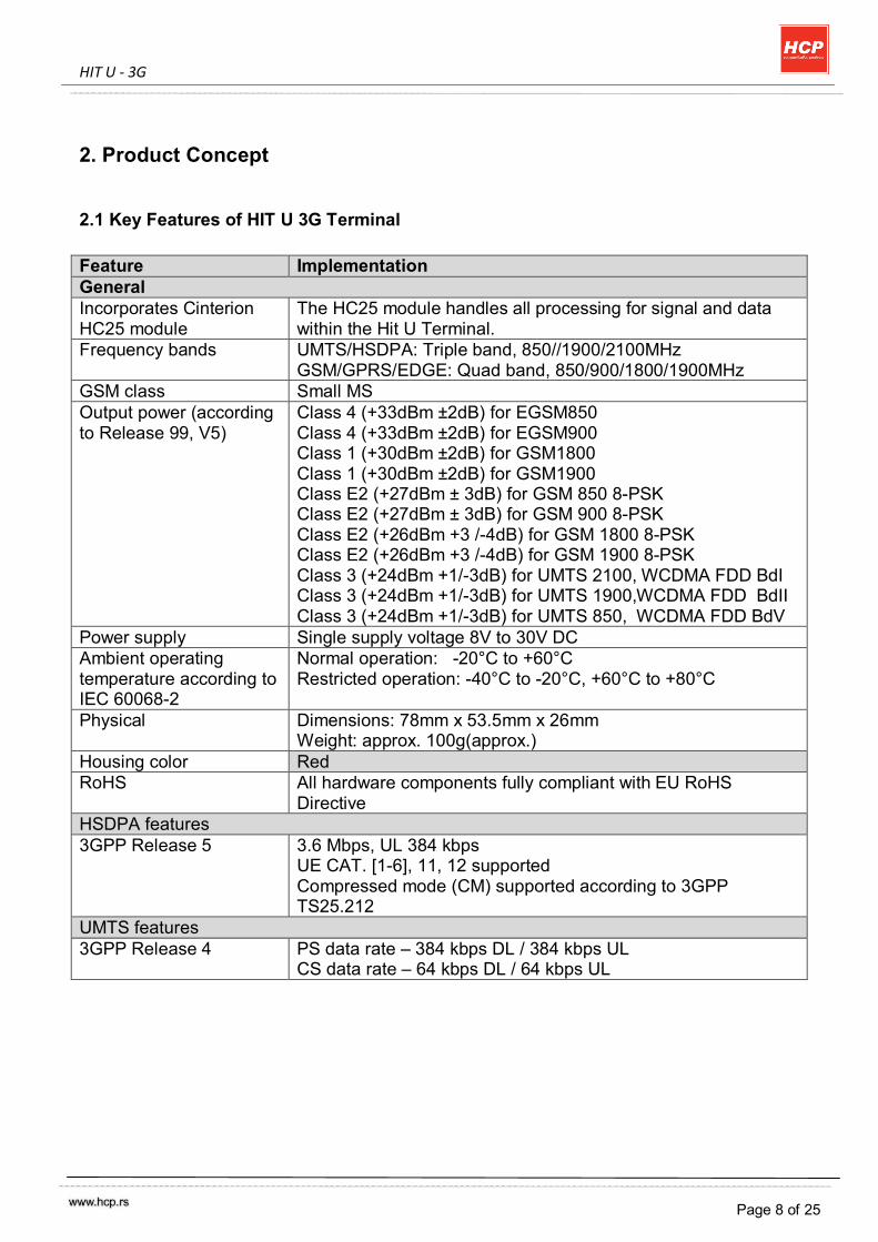
2.1 Key Features of HIT U 3G Terminal Feature Implementation General Incorporates Cinterion HC25 module
The HC25 module handles all processing for signal and data within the Hit U Terminal.
Frequency bands UMTS/HSDPA: Triple band, 850//1900/2100MHz GSM/GPRS/EDGE: Quad band, 850/900/1800/1900MHz
GSM class Small MS Output power (according to Release 99, V5)
Class 4 (+33dBm ±2dB) for EGSM850 Class 4 (+33dBm ±2dB) for EGSM900 Class 1 (+30dBm ±2dB) for GSM1800 Class 1 (+30dBm ±2dB) for GSM1900 Class E2 (+27dBm ± 3dB) for GSM 850 8-PSK Class E2 (+27dBm ± 3dB) for GSM 900 8-PSK Class E2 (+26dBm +3 /-4dB) for GSM 1800 8-PSK Class E2 (+26dBm +3 /-4dB) for GSM 1900 8-PSK Class 3 (+24dBm +1/-3dB) for UMTS 2100, WCDMA FDD BdI Class 3 (+24dBm +1/-3dB) for UMTS 1900,WCDMA FDD BdII Class 3 (+24dBm +1/-3dB) for UMTS 850, WCDMA FDD BdV
Power supply Single supply voltage 8V to 30V DC Ambient operating temperature according to IEC 60068-2
Normal operation: -20°C to +60°C Restricted operation: -40°C to -20°C, +60°C to +80°C
Physical Dimensions: 78mm x 53.5mm x 26mm Weight: approx. 100g(approx.)
Housing color Red RoHS All hardware components fully compliant with EU RoHS
Directive HSDPA features 3GPP Release 5 3.6 Mbps, UL 384 kbps
UE CAT. [1-6], 11, 12 supported Compressed mode (CM) supported according to 3GPP TS25.212
UMTS features 3GPP Release 4 PS data rate – 384 kbps DL / 384 kbps UL
CS data rate – 64 kbps DL / 64 kbps UL
HIT U - 3G
Page 9 of 25
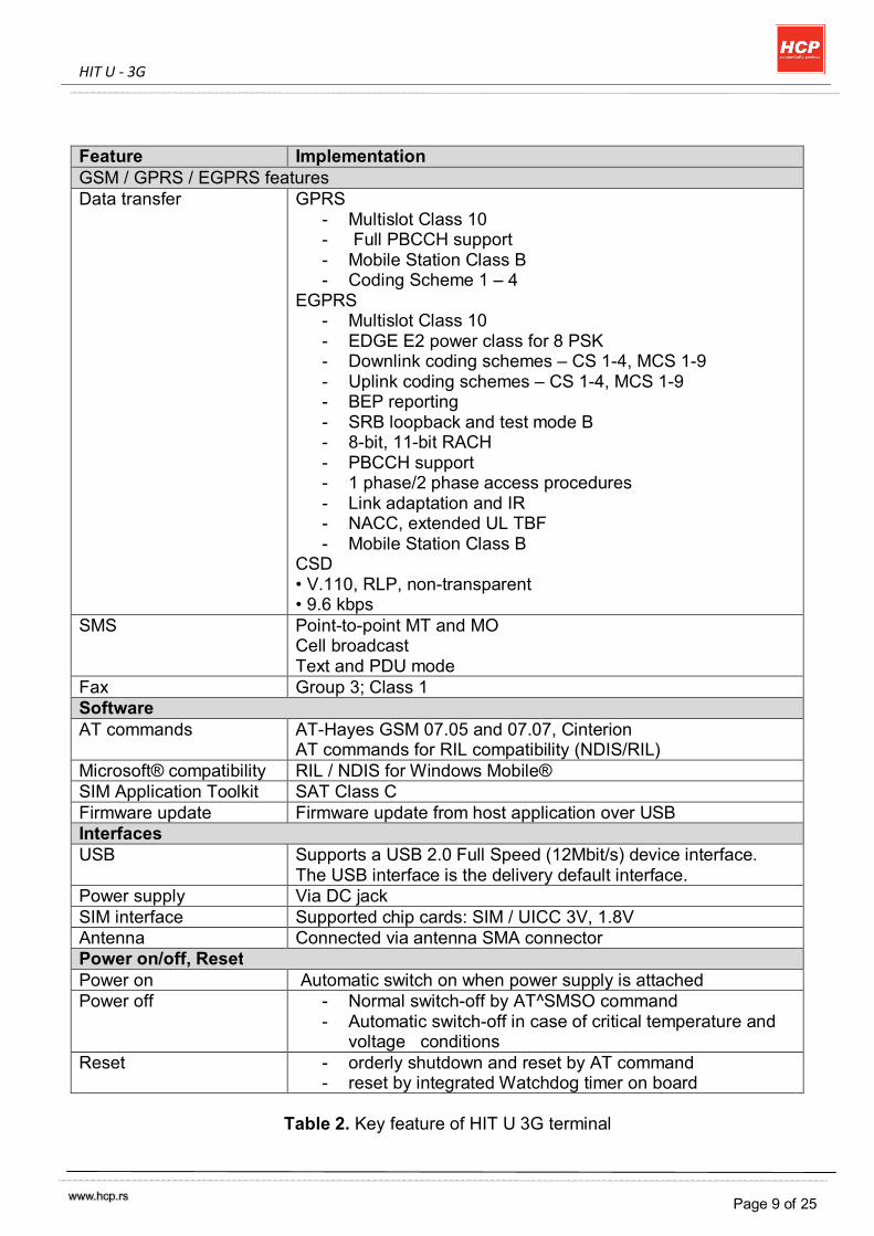
Feature Implementation GSM / GPRS / EGPRS features Data transfer GPRS
- Multislot Class 10 - Full PBCCH support - Mobile Station Class B - Coding Scheme 1 – 4
EGPRS - Multislot Class 10 - EDGE E2 power class for 8 PSK - Downlink coding schemes – CS 1-4, MCS 1-9 - Uplink coding schemes – CS 1-4, MCS 1-9 - BEP reporting - SRB loopback and test mode B - 8-bit, 11-bit RACH - PBCCH support - 1 phase/2 phase access procedures - Link adaptation and IR - NACC, extended UL TBF - Mobile Station Class B
CSD • V.110, RLP, non-transparent • 9.6 kbps
SMS Point-to-point MT and MO Cell broadcast Text and PDU mode
Fax Group 3; Class 1 Software AT commands AT-Hayes GSM 07.05 and 07.07, Cinterion
AT commands for RIL compatibility (NDIS/RIL) Microsoft® compatibility RIL / NDIS for Windows Mobile® SIM Application Toolkit SAT Class C Firmware update Firmware update from host application over USB Interfaces USB Supports a USB 2.0 Full Speed (12Mbit/s) device interface.
The USB interface is the delivery default interface. Power supply Via DC jack SIM interface Supported chip cards: SIM / UICC 3V, 1.8V Antenna Connected via antenna SMA connector Power on/off, Reset Power on Automatic switch on when power supply is attached Power off - Normal switch-off by AT^SMSO command
- Automatic switch-off in case of critical temperature and voltage conditions
Reset - orderly shutdown and reset by AT command - reset by integrated Watchdog timer on board
Table 2. Key feature of HIT U 3G terminal
HIT U - 3G
Page 10 of 25
3. Interface Description
3.1 Overview
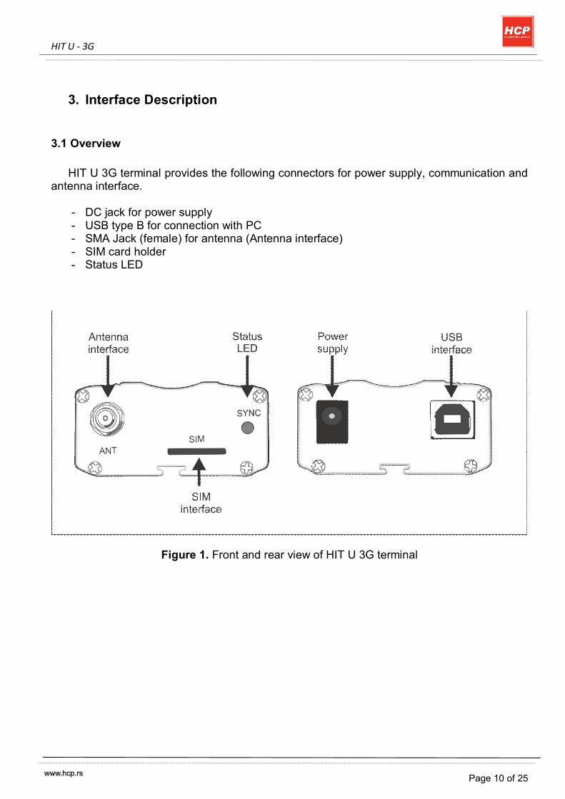
HIT U 3G terminal provides the following connectors for power supply, communication and antenna interface.
- DC jack for power supply - USB type B for connection with PC - SMA Jack (female) for antenna (Antenna interface) - SIM card holder - Status LED
Figure 1. Front and rear view of HIT U 3G terminal
HIT U - 3G
Page 11 of 25
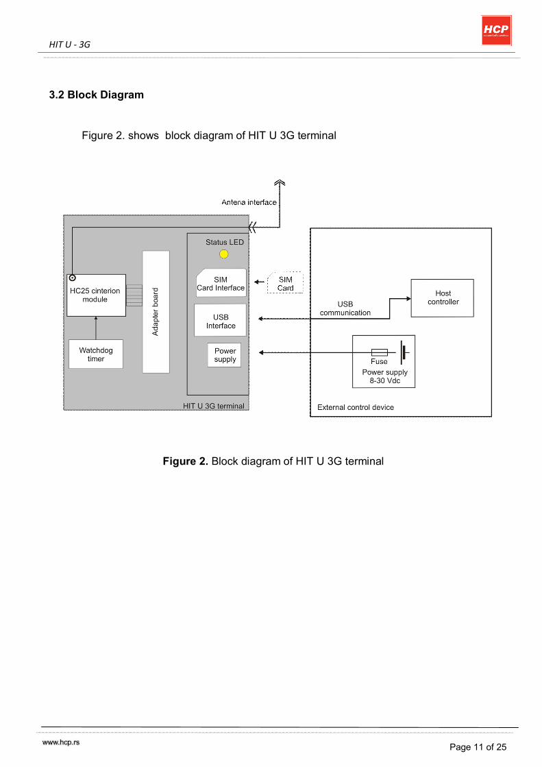
3.2 Block Diagram Figure 2. shows block diagram of HIT U 3G terminal
Figure 2. Block diagram of HIT U 3G terminal
HIT U - 3G
Page 12 of 25
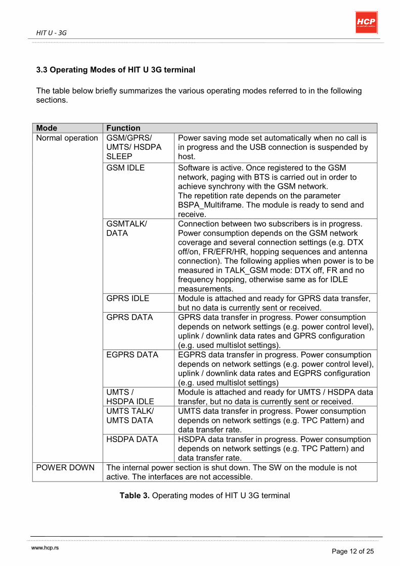
3.3 Operating Modes of HIT U 3G terminal The table below briefly summarizes the various operating modes referred to in the following sections. Mode Function Normal operation GSM/GPRS/
UMTS/ HSDPA SLEEP
Power saving mode set automatically when no call is in progress and the USB connection is suspended by host.
GSM IDLE Software is active. Once registered to the GSM network, paging with BTS is carried out in order to achieve synchrony with the GSM network. The repetition rate depends on the parameter BSPA_Multiframe. The module is ready to send and receive.
GSMTALK/ DATA
Connection between two subscribers is in progress. Power consumption depends on the GSM network coverage and several connection settings (e.g. DTX off/on, FR/EFR/HR, hopping sequences and antenna connection). The following applies when power is to be measured in TALK_GSM mode: DTX off, FR and no frequency hopping, otherwise same as for IDLE measurements.
GPRS IDLE Module is attached and ready for GPRS data transfer, but no data is currently sent or received.
GPRS DATA GPRS data transfer in progress. Power consumption depends on network settings (e.g. power control level), uplink / downlink data rates and GPRS configuration (e.g. used multislot settings).
EGPRS DATA EGPRS data transfer in progress. Power consumption depends on network settings (e.g. power control level), uplink / downlink data rates and EGPRS configuration (e.g. used multislot settings)
UMTS / HSDPA IDLE
Module is attached and ready for UMTS / HSDPA data transfer, but no data is currently sent or received.
UMTS TALK/ UMTS DATA
UMTS data transfer in progress. Power consumption depends on network settings (e.g. TPC Pattern) and data transfer rate.
HSDPA DATA HSDPA data transfer in progress. Power consumption depends on network settings (e.g. TPC Pattern) and data transfer rate.
POWER DOWN The internal power section is shut down. The SW on the module is not active. The interfaces are not accessible.
Table 3. Operating modes of HIT U 3G terminal
HIT U - 3G
Page 13 of 25
3.4 Power Supply
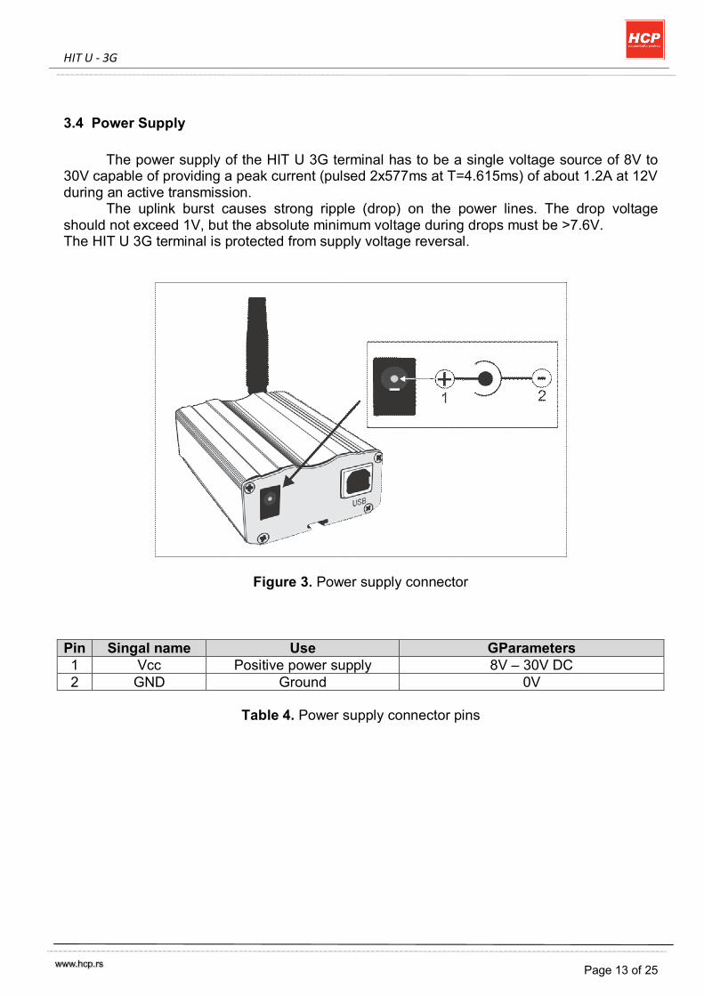
The power supply of the HIT U 3G terminal has to be a single voltage source of 8V to 30V capable of providing a peak current (pulsed 2x577ms at T=4.615ms) of about 1.2A at 12V during an active transmission.
The uplink burst causes strong ripple (drop) on the power lines. The drop voltage should not exceed 1V, but the absolute minimum voltage during drops must be >7.6V. The HIT U 3G terminal is protected from supply voltage reversal.
Figure 3. Power supply connector
Pin Singal name Use GParameters 1 Vcc Positive power supply 8V – 30V DC 2 GND Ground 0V
Table 4. Power supply connector pins
HIT U - 3G
Page 14 of 25
3.4.1 Turn HIT U terminal on
Hit U GMS module switches on automaticly when power supply is attached. After start-up, the GSM module enters the net searching state.
3.4.2 Reset HIT U terminal
One way to reset HIT U terminal is entering AT command AT+CFUN=x,1. For details on AT+CFUN please refer to [2]. Other ways for restarting HIT U terminal is:
- unplug both, power supply from DC jack and USB cable
- automatically by integrated watchdog timer on every 8 to 10 hours.
3.4.3 Turn off HIT U terminal
Normal shutdown:
- To turn off the HIT U use the AT^SMSO command, rather than disconnecting the power supply adapter.
This procedure lets the HIT U log off from the network and allows the software to
enter a secure state and save data before disconnecting the power supply. After AT^SMSO has been entered the HIT U returns the following result codes: ^SMSO: MS OFF OK ^SHUTDOWN
The "^SHUTDOWN" result code indicates that the HIT U turns off in less than 1 second. After the shutdown procedure is complete the HIT U enters the POWER DOWN mode. The status LED stops flashing.
3.4.4 Disconnecting power supply
Before disconnecting the power supply from the DC connector, make sure that the HIT U 3G terminal is in a safe condition. The best way is to wait 1s after the "^SHUTDOWN" result code has been indicated.

HIT U - 3G
Page 15 of 25
3.4.5 Automatic thermal shutdown Automatic shutdown takes effect if:
- Hit U GSM module HC25 exceeds the critical limits of overtemperature or undertemperature .
The board temperature is constantly monitore d by an internal NTC resistor. The values detected by the NTC resistor are measured directly on the board and are therefore not fully identical with the ambient temperature. Each time the board temperature goes out of range or back to normal, HC25 instantly displays an alert (if enabled).
- URCs indicating the level "1" or "-1" allow the user to take appropriate precautions, such as protecting the module from exposure to extreme conditions. The presentation of the URCs depends on the settings selected with the AT^SCTM write command:
AT^SCTM=1: Presentation of URCs is always enabled. AT^SCTM=0 (default): Presentation of URCs is enabled for 15 seconds time after start-up of HC25. After 15 seconds operation, the presentation will be disabled, i.e. no alert messages can be generated.
For more information about automatic shutdown refer to [1].
HIT U - 3G
Page 16 of 25
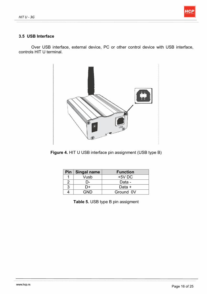
3.5 USB Interface
Over USB interface, external device, PC or other control device with USB interface, controls HIT U terminal.
Figure 4. HIT U USB interface pin assignment (USB type B)
Pin Singal name Function 1 Vusb +5V DC 2 D- Data - 3 D+ Data + 4 GND Ground 0V
Table 5. USB type B pin assigment
HIT U - 3G
Page 17 of 25
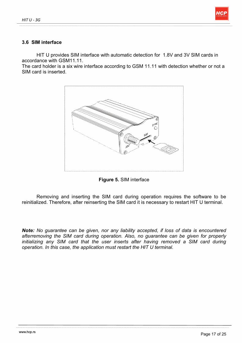
3.6 SIM interface
HIT U provides SIM interface with automatic detection for 1.8V and 3V SIM cards in accordance with GSM11.11. The card holder is a six wire interface according to GSM 11.11 with detection whether or not a SIM card is inserted.
Figure 5. SIM interface
Removing and inserting the SIM card during operation requires the software to be reinitialized. Therefore, after reinserting the SIM card it is necessary to restart HIT U terminal. Note: No guarantee can be given, nor any liability accepted, if loss of data is encountered afterremoving the SIM card during operation. Also, no guarantee can be given for properly initializing any SIM card that the user inserts after having removed a SIM card during operation. In this case, the application must restart the HIT U terminal.
HIT U - 3G
Page 18 of 25
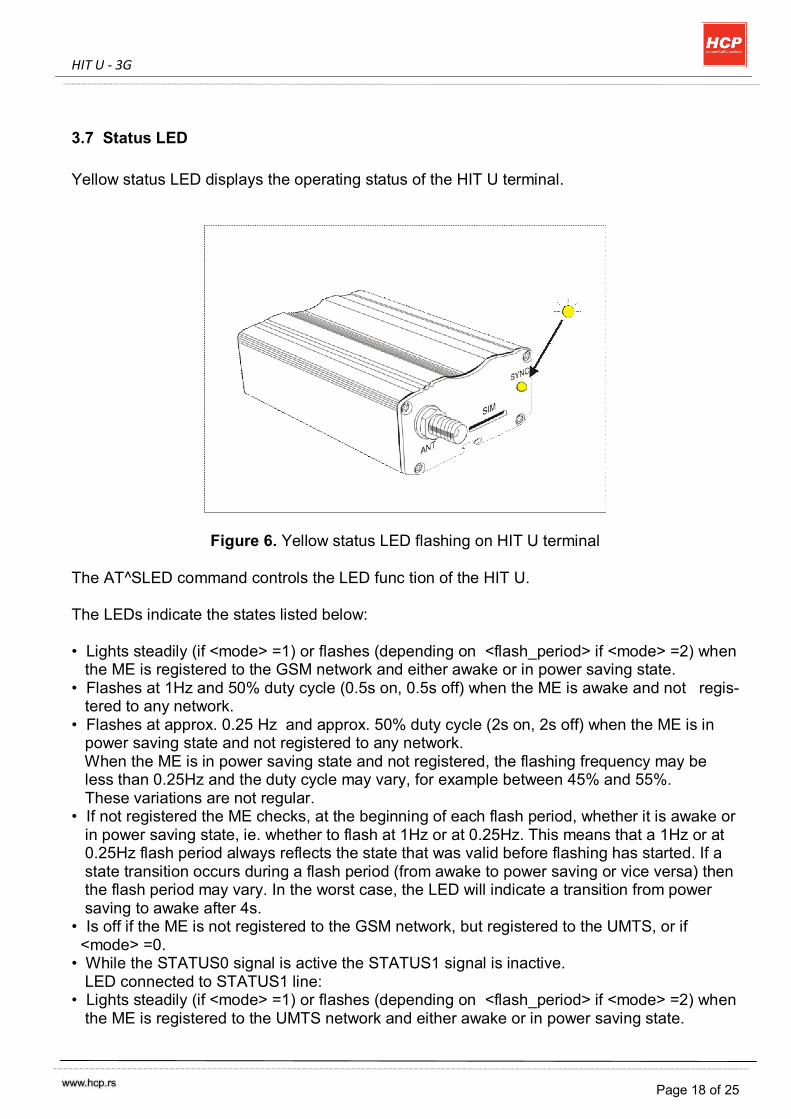
3.7 Status LED Yellow status LED displays the operating status of the HIT U terminal.
Figure 6. Yellow status LED flashing on HIT U terminal
The AT^SLED command controls the LED func tion of the HIT U. The LEDs indicate the states listed below: • Lights steadily (if <mode> =1) or flashes (depending on <flash_period> if <mode> =2) when the ME is registered to the GSM network and either awake or in power saving state. • Flashes at 1Hz and 50% duty cycle (0.5s on, 0.5s off) when the ME is awake and not regis- tered to any network. • Flashes at approx. 0.25 Hz and approx. 50% duty cycle (2s on, 2s off) when the ME is in power saving state and not registered to any network. When the ME is in power saving state and not registered, the flashing frequency may be less than 0.25Hz and the duty cycle may vary, for example between 45% and 55%. These variations are not regular. • If not registered the ME checks, at the beginning of each flash period, whether it is awake or in power saving state, ie. whether to flash at 1Hz or at 0.25Hz. This means that a 1Hz or at 0.25Hz flash period always reflects the state that was valid before flashing has started. If a state transition occurs during a flash period (from awake to power saving or vice versa) then the flash period may vary. In the worst case, the LED will indicate a transition from power saving to awake after 4s. • Is off if the ME is not registered to the GSM network, but registered to the UMTS, or if <mode> =0. • While the STATUS0 signal is active the STATUS1 signal is inactive. LED connected to STATUS1 line: • Lights steadily (if <mode> =1) or flashes (depending on <flash_period> if <mode> =2) when the ME is registered to the UMTS network and either awake or in power saving state.
HIT U - 3G
Page 19 of 25
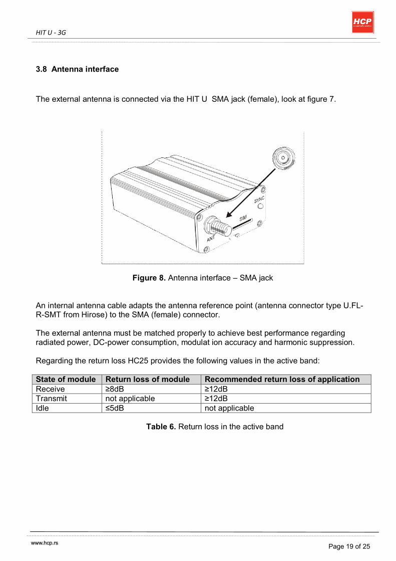
3.8 Antenna interface The external antenna is connected via the HIT U SMA jack (female), look at figure 7.
Figure 8. Antenna interface – SMA jack
An internal antenna cable adapts the antenna reference point (antenna connector type U.FL-R-SMT from Hirose) to the SMA (female) connector. The external antenna must be matched properly to achieve best performance regarding radiated power, DC-power consumption, modulat ion accuracy and harmonic suppression. Regarding the return loss HC25 provides the following values in the active band:
State of module Return loss of module Recommended return loss of application Receive ≥8dB ≥12dB Transmit not applicable ≥12dB Idle ≤5dB not applicable
Table 6. Return loss in the active band
HIT U - 3G
Page 20 of 25
4. Electrical and Environmental Characteristics
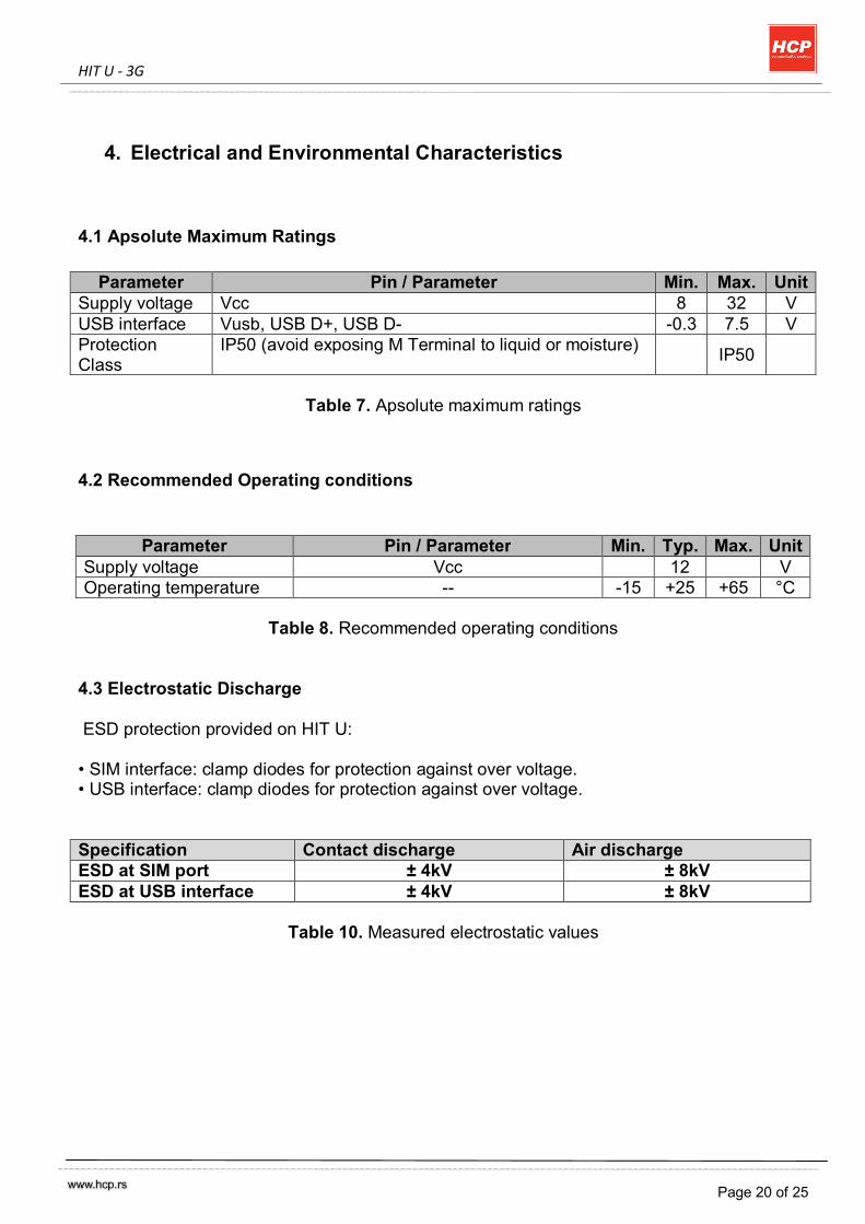
4.1 Apsolute Maximum Ratings
Parameter Pin / Parameter Min. Max. Unit Supply voltage Vcc 8 32 V USB interface Vusb, USB D+, USB D- -0.3 7.5 V Protection Class
IP50 (avoid exposing M Terminal to liquid or moisture) IP50
Table 7. Apsolute maximum ratings
4.2 Recommended Operating conditions
Parameter Pin / Parameter Min. Typ. Max. Unit Supply voltage Vcc 12 V Operating temperature -- -15 +25 +65 °C
Table 8. Recommended operating conditions
4.3 Electrostatic Discharge ESD protection provided on HIT U: • SIM interface: clamp diodes for protection against over voltage. • USB interface: clamp diodes for protection against over voltage. Specification Contact discharge Air discharge ESD at SIM port ± 4kV ± 8kV ESD at USB interface ± 4kV ± 8kV
Table 10. Measured electrostatic values
HIT U - 3G
Page 21 of 25
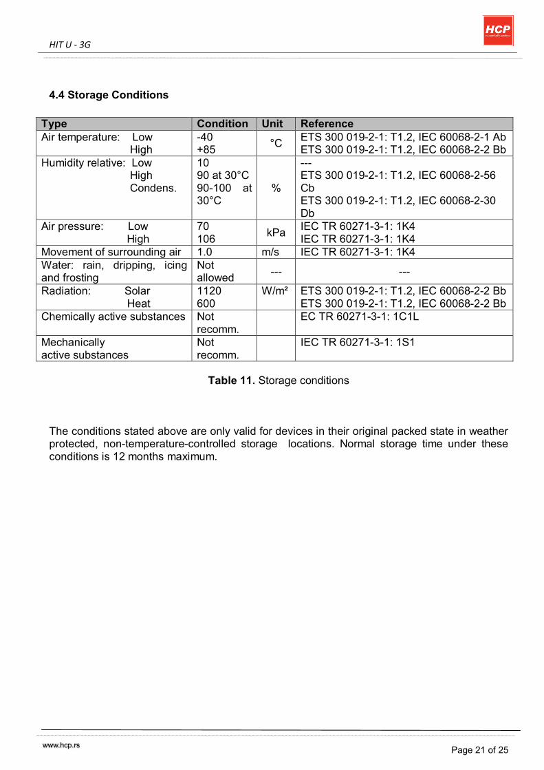
4.4 Storage Conditions
Type Condition Unit Reference Air temperature: Low High
-40 +85 °C ETS 300 019-2-1: T1.2, IEC 60068-2-1 Ab
ETS 300 019-2-1: T1.2, IEC 60068-2-2 Bb Humidity relative: Low High Condens.
10 90 at 30°C 90-100 at 30°C
%
--- ETS 300 019-2-1: T1.2, IEC 60068-2-56 Cb ETS 300 019-2-1: T1.2, IEC 60068-2-30 Db
Air pressure: Low High
70 106 kPa IEC TR 60271-3-1: 1K4
IEC TR 60271-3-1: 1K4 Movement of surrounding air 1.0 m/s IEC TR 60271-3-1: 1K4 Water: rain, dripping, icing and frosting
Not allowed --- ---
Radiation: Solar Heat
1120 600
W/m² ETS 300 019-2-1: T1.2, IEC 60068-2-2 Bb ETS 300 019-2-1: T1.2, IEC 60068-2-2 Bb
Chemically active substances Not recomm.
EC TR 60271-3-1: 1C1L
Mechanically active substances
Not recomm.
IEC TR 60271-3-1: 1S1
Table 11. Storage conditions
The conditions stated above are only valid for devices in their original packed state in weather protected, non-temperature-controlled storage locations. Normal storage time under these conditions is 12 months maximum.

HIT U - 3G
Page 22 of 25
4.5 Electrical Specifications of the Application Interface
4.5.1 USB interface
Hit U supports a USB 2.0 Full Speed (12Mbit/s) device interface. A USB host has to supportat least 6 „Message Pipes“ (see “Universal Serial Bus Specification Revision 2.0“3 for a definition of the term „Message Pipe“) to work with the Hit U USB interface.
The USB I/O-pins are capable of driving the signal at min 3.0V. They are 5V I/O
compliant.The Hit U module HC25 USB interface is powered by VUSB. VUSB must be supplied by the USB host in the range 4.5V to 5.25V The maximum load on VUSB is 10mA. While the USB connection is active, the module will not change into SLEEP Mode. To enable switching into SLEEP mode the USB host must bring its USB interface into Suspend state (see “Universal Serial Bus Specification Revision 2.0“3 for a description of the Suspend state). On incoming calls HC25 will then generate a remote wake up request to resume the USB connection. For more information about USB interface pins refer to [2], and for more information on on how to configure the USB interface by means of AT commands see [1].
4.5.2 Antenna interface
Parameter Conditions Min. Typ. Max. Unit HSDPA/UMTS connectivity Band I, II, V UMTS Frequency range Uplink (UE to Node B)
UMTS 850 Band V 824 849 MHz UMTS 1900 Band II 1850 1910 MHz UMTS 2100 Band I 1920 1980 MHz
UMTS Frequency range Downlink (Node B to UE)
UMTS 850 Band V 869 894 MHz UMTS 1900 Band II 1930 1990 MHz UMTS 2100 Band I 2110 2170 MHz
RF Power@ ARP with 50Ohm Load
UMTS 850 Band V +21 +23 +25 dBm UMTS 1900 Band II +21 +23 +25 dBm UMTS 2100 Band I +21 +23 +25 dBm
Table x. Antena interface
Please refer to [2] for more information about antenna interface (air interface).
HIT U - 3G
Page 23 of 25
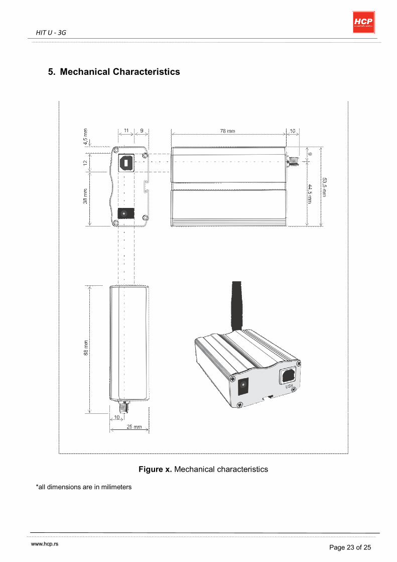
5. Mechanical Characteristics
Figure x. Mechanical characteristics
*all dimensions are in milimeters
HIT U - 3G
Page 24 of 25
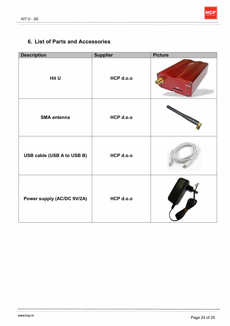
6. List of Parts and Accessories Description Supplier Picture
Hit U HCP d.o.o
SMA antenna HCP d.o.o
USB cable (USB A to USB B) HCP d.o.o
Power supply (AC/DC 9V/2A) HCP d.o.o
HIT U - 3G
Page 25 of 25
HCP d.o.o. Mirka Tomica – pasaz 37000 Krusevac SERBIA
Phn. +381.37.445.401
+381.37.418.790 Fax. +381.37.448.351 Website www.hcp.rs
Sales email: [email protected]
Support: [email protected]
Development: [email protected]