Helicopter deck on offshore installations · NORSOK Standard C-004 Edition 2, May 2013 Helicopter...
24
NORSOK Standard C-004 Edition 2, May 2013 Helicopter deck on offshore installations This NORSOK standard is developed with broad petroleum industry participation by interested parties in the Norwegian petroleum industry and is owned by the Norwegian petroleum industry represented by the Norwegian Oil and Gas Association and The Federation of Norwegian Industries. Please note that whilst every effort has been made to ensure the accuracy of this NORSOK standard, neither the Norwegian Oil and Gas Association nor The Federation of Norwegian Industries or any of their members will assume liability for any use thereof. Standards Norway is responsible for the administration and publication of this NORSOK standard. Standards Norway Telephone: + 47 67 83 86 00 Strandveien 18, P.O. Box 242 Fax: + 47 67 83 86 01 N-1326 Lysaker Email: [email protected] NORWAY Website: www.standard.no/petroleum Copyrights reserved © NORSOK. Any enquiries regarding reproduction should be addressed to Standard Online AS. www.standard.no
Transcript of Helicopter deck on offshore installations · NORSOK Standard C-004 Edition 2, May 2013 Helicopter...
NORSOK Standard
C-004 Edition 2, May 2013
Helicopter deck on offshore installations
This NORSOK standard is developed with broad petroleum industry participation by interested parties in the Norwegian petroleum industry and is owned by the Norwegian petroleum industry represented by the Norwegian Oil and Gas Association and The Federation of Norwegian Industries. Please note that whilst every effort has been made to ensure the accuracy of this NORSOK standard, neither the Norwegian Oil and Gas Association nor The Federation of Norwegian Industries or any of their members will assume liability for any use thereof. Standards Norway is responsible for the administration and publication of this NORSOK standard.
Standards Norway Telephone: + 47 67 83 86 00 Strandveien 18, P.O. Box 242 Fax: + 47 67 83 86 01 N-1326 Lysaker Email: [email protected] NORWAY Website: www.standard.no/petroleum
Copyrights reserved
© NORSOK. Any enquiries regarding reproduction should be addressed to Standard Online AS. www.standard.no

NORSOK Standard C-004, Edition 2, May 2013
NORSOK © 2013 1
NORSOK Standard C-004
Helicopter deck on offshore installations
Contents
1 Scope ..................................................................................................................................................... 3
2 Normative and informative references ................................................................................................... 3 2.1 Normative references ................................................................................................................... 3 2.2 Informative references ................................................................................................................. 3
3 Terms, definitions and abbreviations ..................................................................................................... 3 3.1 Terms and definitions ................................................................................................................... 3 3.2 Abbreviations ............................................................................................................................... 5
4 General requirements ............................................................................................................................. 5
5 Environmental effects ............................................................................................................................. 6 5.1 Wind analysis ............................................................................................................................... 6 5.2 Wind ............................................................................................................................................. 7 5.3 Structure induced turbulence ....................................................................................................... 7 5.4 Hot air flow ................................................................................................................................... 7 5.5 Hydrocarbon gas emission .......................................................................................................... 9 5.6 Ocean waves and installations in motion ..................................................................................... 9
6 Helicopter deck monitoring systems ...................................................................................................... 9
7 Visual points of reference (visual cues) ................................................................................................. 9
8 Helideck location .................................................................................................................................. 10
9 Obstacle-free sector, (OFS) ................................................................................................................. 10
10 Limited obstacle sector (LOS) .............................................................................................................. 10
11 Falling 5:1 gradient ............................................................................................................................... 12
12 Helideck design .................................................................................................................................... 12
13 Helideck materials and fabrication ....................................................................................................... 13
14 Helideck surface friction ....................................................................................................................... 13
15 Sub-zero conditions .............................................................................................................................. 13
16 Lowered perimeter walkway/safety net ................................................................................................ 14
17 Fire and rescue preparedness ............................................................................................................. 15 17.1 General ...................................................................................................................................... 15 17.2 Helideck drainage and passive fire suppression ....................................................................... 15
18 Lighting ................................................................................................................................................. 15 18.1 General ...................................................................................................................................... 15 18.2 Perimeter lights .......................................................................................................................... 16 18.3 Flood lights ................................................................................................................................. 16 18.4 Illumination of lowered perimeter walkway ................................................................................ 16 18.5 Windsock (wind direction indicator) ........................................................................................... 17 18.6 Warning lights, etc. ..................................................................................................................... 17
19 Cargo handling ..................................................................................................................................... 17
20 Tie-down points .................................................................................................................................... 17
NORSOK Standard C-004, Edition 2, May 2013
NORSOK © 2013 2
21 Auxiliary equipment ..............................................................................................................................17
22 Access by installation crane .................................................................................................................18
23 Marking .................................................................................................................................................18
24 Signs .....................................................................................................................................................18
25 Inspection and maintenance access ....................................................................................................18
Foreword
The NORSOK standards are developed by the Norwegian petroleum industry to ensure adequate safety, value adding and cost effectiveness for petroleum industry developments and operations. Furthermore, NORSOK standards are as far as possible intended to replace oil company specifications and serve as references in the authorities’ regulations.
The NORSOK standards are normally based on recognised international standards, adding the provisions deemed necessary to fill the broad needs of the Norwegian petroleum industry. Where relevant, NORSOK standards will be used to provide the Norwegian industry input to the international standardisation process. Subject to development and publication of international standards, the relevant NORSOK standard will be withdrawn.
The NORSOK standards are developed according to the consensus principle generally applicable standards work and according to established procedures defined in NORSOK A-001.
The NORSOK standards are prepared and published with support by the Norwegian Oil and Gas Association and the Federation of Norwegian Industries.
NORSOK standards are administered and published by Standards Norway.
Introduction
This NORSOK standard is based on practical experiences accumulated from helicopter operations on the Norwegian continental shelf. A primary goal of this standard is to set the framework for maximising flight safety and regularity on offshore helidecks.
This standard has been written and revised by NORSOK committee EGC.
Main changes from first edition to second edition are in summary:
general formatting and reformulation of text;
inclusion of operational experience feedback from recent projects;
new sections 5, 8, 13 and 15;
updates on flight environment and turbulence;
updates on LOS segment lines;
updates on sub-zero conditions;
updates on lowered walkway;
updates on helideck drainage and passive fire suppression;
updates on helideck lighting.
NORSOK Standard C-004, Edition 2, May 2013
NORSOK © 2013 3
1 Scope
This NORSOK standard defines the basic requirements for design, arrangement and engineering of helicopter decks on offshore installations in the petroleum industry. This NORSOK standard covers fixed type installations, normally unmanned installations, floating installations, production, drilling and storage vessels.
2 Normative and informative references
The following standards include provisions and guidelines which, through reference in this text, constitute provisions and guidelines of this NORSOK standard. Latest issue of the references shall be used unless otherwise agreed. Other recognized standards may be used provided it can be shown that they meet or exceed the requirements and guidelines of the standards referenced below.
2.1 Normative references
NORSOK C-002, Architectural components and equipment
NORSOK M-501, Surface preparation and protective coating
NORSOK N-001, Integrity of offshore structure
NORSOK N-002, Collection of met ocean data
NORSOK S-001, Technical safety
NORSOK S-002, Working environment
EN 1090-3, Execution of steel structures and aluminium structures, Part 3: Technical requirements for aluminium structures
BSL D 5-1,(FOR 1181), Bestemmelser for sivil luftfart (Regulation for civil aviation Norway)
ICAO, Annex 14
2.2 Informative references
None.
3 Terms, definitions and abbreviations
For the purposes of this NORSOK standard, the following terms, definitions and abbreviations apply.
3.1 Terms and definitions
3.1.1 5:1 gradient the falling 5:1 gradient is measured from the top of the lowered gangway railing (or safety netting) to the sea level within the 180° horizontal sector that passes through the centre of the helideck and outwards
3.1.2 can verbal form used for statements of possibility and capability, whether material, physical or casual
3.1.3 de-icing defined as removal of snow, ice and frost from a surface
3.1.4 DH-value the minimum permissible diameter of the helideck equal to the helicopter D-value multiplied by a factor of 1,25. In certain cases this factor may be increased to improve safety and landing margins, (see chapter 14)
NORSOK Standard C-004, Edition 2, May 2013
NORSOK © 2013 4
3.1.5 D-value the largest overall dimension of the helicopter with both rotors turning. Normally measured from the most forward position of the main rotor blade plane to the most rearward position of the tail rotor blade plane, (or fuselage when relevant)
3.1.6 helicopter landing officer (HLO) the person in charge of the daily supervision of the helideck
3.1.7 helideck dedicated helicopter landing area on offshore installations
3.1.8 helideck circle normally a hypothetical circle, (unless the helideck itself is circular), circumscribing the landing area of the helideck with a diameter equal to the deck’s DH-value
3.1.9 helideck limitation list a list used by pilots to describe any operational restrictions for a specific helideck
3.1.10 limited obstacle sector defined as the 150° sector where obstacle are permitted within certain height limitations and distances
3.1.11 may verbal form used to indicate a course of action permissible within the limits of this NORSOK standard
3.1.12 obstacle-free sector defined as the 210° safe approach and take-off sector for helicopters with an unobstructed flight path above the helideck plane to a safe calculated distance for the helicopter the deck is dimensioned for, normally 500 meters
3.1.13 perimeter line a white painted 300 mm wide line surrounding the helideck, where the outside edge marks the border of the safe landing area as defined by the helideck’s DH-value
3.1.14 helideck size marking a whole number inscribed in the perimeter line at three positions with an angle spacing of 90°, marking the D-value for the largest helicopter the helideck is dimensioned for, rounded to the nearest whole number
3.1.15 run-off area an extension from the helideck to a dedicated helicopter parking area and/or helicopter hangar(s)
3.1.16 shall verbal form used to indicate requirements strictly to be followed in order to conform to this NORSOK standard and from which no deviation is permitted, unless accepted by all involved parties
NORSOK Standard C-004, Edition 2, May 2013
NORSOK © 2013 5
3.1.17 should verbal form used to indicate that among several possibilities one is recommended as particularly suitable, without mentioning or excluding others, or that a certain course of action is preferred but not necessarily required
3.1.18 touchdown circle (TD circle) the yellow inner circle marking the pilots’ aiming point for a safe touchdown of the undercarriage within the landing area. Correct touchdown allows for safe access, cargo handling and other required services on the helideck
3.2 Abbreviations
BSL Bestemmelser for sivil luftfart (regulation for civil aviation)
CFD computational fluid dynamics
DIFFS deck integrated fire fighting system
FMS foam monitor system
FPSO floating production storage offloading
helideck helicopter deck
HLL helideck limitation list
HLO helicopter landing officer
HTCC helicopter traffic control centre
ICAO International Civil Aviation Organisation
LED light emitting diode
LOS limited obstacle sector
LQ living quarters
MTOM maximum take-off mass
OFS obstacle-free sector
TD Circle touchdown circle
UPS uninterrupted power supply
NVG night vision goggles
4 General requirements
The provisions set forth in this NORSOK standard shall be complied with in all phases of planning, construction and operation of the helideck. It shall be read in conjunction with the regulation in force, and in particular the Norwegian Civil Aviation Authority (CAA) document BSL D5-1.
The helideck design and location shall be seen as an integrated part of the overall offshore installation design, and not as an isolated activity. This is due to the fact that there are several elements on, and around, an offshore installation that may severely affect safe helicopter operations, unless appropriate measures are taken to avoid, control or reduce any potential hazards. Perfect conditions at all times on a densely equipped petroleum platform or vessel may be hard to achieve, since there are likely to be some potential conflicting situations. In view of this the design approach shall be based on a rational evaluation and decision-making process to achieve the very best compromise when conflicting requirements occur.
NORSOK Standard C-004, Edition 2, May 2013
NORSOK © 2013 6
The design process shall start at an early stage, and run in parallel with other design activities on the installation. The objective is to achieve a functional and safe helideck with safe approach and departure sectors that will facilitate high flight regularity under most operational conditions. Any potential flight limitation shall either be resolved, or registered as a limitation in HLL.
NOTE Poorly designed helidecks may cause serious helicopter operational restrictions with significant commercial and operational penalties.
5 Environmental effects
The immediate environment surrounding offshore installations may affect helicopter operations in various ways. Bad weather, buildings, structures, equipment, processes and systems may in certain circumstances induce unsafe conditions near the helideck that requires attention. Such conditions are typically:
poor visibility (day and night);
unfavourable wind directions;
structure induced turbulence;
thermal effects and turbulence caused by gas turbine exhausts, flares and diesel engine emissions;
unburned hydrocarbon gas emissions from cold flaring;
emissions from emergency blow down systems;
helideck motion caused by ocean waves;
poor visual points of references/visual cues;
obstacles adjacent to the helideck.
These conditions rarely act independently of each other, and several may occur at the same time. An important task shall be to evaluate these conditions, examine cause and effect, and take necessary actions to provide optimal operational conditions at the helideck. An in-depth understanding of these phenomena and their potential impact is a key factor for a successful helideck design.
The environmental effects shall be correlated with the performance and the sensitivity of the relevant helicopter types to be used on the offshore installation.
The design shall take into account any impact caused by neighbouring installation(s).
5.1 Wind analysis
CFD analyses or wind tunnel tests shall be performed to describe the air flow and hot gas dispersion close to the helideck. A suitable model of the installation shall be built, where relevant environmental effects shall be simulated and evaluated for various conditions. The findings shall be correlated with practical experience data, historic wind data, and relevant information from the helicopter operator. Conclusions and recommendations shall verify and document that the helideck has been given an optimal location on the installation in question. Any possible problems or restrictions regarding helicopter operations shall be highlighted, to enable necessary corrective actions.
Similarly, CFD analyses or wind tunnel tests shall be performed when modifications on existing installations may affect flight performance on the helideck,
The volume of air space to be considered shall comprise the immediate air space surrounding the offshore installation that may induce unfavourable operational conditions at the helideck, and in the helicopter approach and departure sector. The helicopter landing and take-off committal points shall be deemed to be up to 20 meters above the helideck.
Mapping and visualisation of the wind velocity field shall be provided in the form of plots of velocity magnitude, vertical velocity component and vertical velocity fluctuations above the helideck. Vertical velocity fluctuations to be presented are 1,75 m/s and 2,4 m/s. Operational experience indicates that velocity fluctuation of 1.75 m/s will generate noticeable turbulence. This criterion should therefore normally not be exceeded. Flight limitations are likely at values exceeding 2,4 m/s.
NOTE The above values have been aligned with recommendations in CAP 437 7th and 5th editions, respectively.
NORSOK Standard C-004, Edition 2, May 2013
NORSOK © 2013 7
A differential turbulence model shall be used for the simulations to provide a physical representation of the anisotropy of the turbulence field close to the helideck.
5.2 Wind
The basic design principle shall be to locate the helideck in such a manner that the 210° obstacle-free approach and take-off sector have the most favourable direction in relation to the prevailing wind sector.
A windsock shall be provided to indicate the true wind direction, by locating it in an area of negligible turbulence. It shall be clearly seen by the pilots in the flight approach sector and from the take-off position on the helideck, day and night.
The windsock shall have a conical shape and shall be of a suitable size. The colour shall be plain orange, or red/white, unless specified otherwise.
NOTE More than one windsock may be required in order to comply with this requirement.
5.3 Structure induced turbulence
Structure induced turbulence is created by wind hitting buildings, structures and equipment, and is in most cases predictable. Strong turbulent air flow should be avoided within the operational environment of the helicopter since it may adversely affect the performance and handling.
NOTE Turbulence around an offshore installation is a major risk factor for helicopter operations, and presents a considerable workload on the pilots.
Structure induced turbulence shall be carefully assessed and documented through CFD analyses or wind tunnel tests. Findings that may endanger helicopter operations, or cause operational restrictions, shall be rectified through necessary design modifications. The objective shall be to eliminate significant structure induced turbulence at the helideck, and in the helicopter approach and take-off sector.
Typical sources of structure induced turbulence are tall solid buildings and structures, plated derricks, cranes, exhaust stacks, etc. Such elements may cause severe turbulent airflow downwind, and may for certain wind directions pose a hazard to helicopter operations. Open or relatively porous structures may reduce this effect considerably and should be encouraged whenever possible.
Lay-down decks in the vicinity of the helideck should be avoided, since bulky containers and tall items placed temporarily on the deck may cause unexpected turbulence.
New modules or structures installed on an existing offshore installation require attention, since they may generate unwanted turbulence near the helideck.
Cantilevered helidecks, supported by an open frame structure, shall be placed level with a roof top or deck when feasible. This will enable flush access to the LQ entrance, parking area, or hangar, and result in minimal disturbed airflow underneath and above the helideck.
An air gap shall be provided beneath the landing area, when the helideck is placed above a building or solid structure. The height of the air gap shall normally be in the range of 2 m to 5 m, or more, depending on the given situation. Placement of the landing area directly on a roof or deck is unacceptable.
5.4 Hot air flow
Offshore installations will normally contain a variety of systems and processes that will emit hot air flows, typically generated by turbine generators, diesel engines and flare(s). Hot air flows from these systems may create turbulence and other thermal effects that may severely affect helicopter operations, unless adequate risk reducing measures are taken at the design stage.
Hot air flow, combined with a sudden change in air temperature, may have the following two major effects on the helicopter performance:
possible momentary stalling of helicopter engines due to sudden air density changes through the turbine compressors;
significant reduction in helicopter lift capacity.
These risks can be controlled by either proper design, which should be the main priority, or by operational measures that may involve certain helicopter flight limitations. The risk varies with helicopter type, and the risk level increases with large temperature gradients in the flight path. In view of this the following 3
NORSOK Standard C-004, Edition 2, May 2013
NORSOK © 2013 8
methods should be assessed, where method 1 represents a deterministic approach, while methods 2 and 3 are risk based approaches:
1) Method 1 is a conservative approach that should be used when designing a new installation. The method is based on CFD analysis and implies that the free airspace above the helideck should not be exposed to temperature increase of more than 2 °C (iso-contour from CFD). The free airspace is defined as a height above the helideck corresponding to approximately 10 m plus wheels-to-rotor height plus one rotor diameter. This method will normally require a minimum exhaust stack height of 30-32 m based on experience data, but should be verified in each case. When several stacks are required the design shall allow for optimal location and alignment to minimize gas plume exposure over the helideck. In difficult cases cooling of the exhaust gas may be considered by use of a reliable waste heat recovery system, or similar, based on a total assessment. In situations where this method is deemed impossible, unpractical or noncompliant, methods 2 and 3 should be considered. These methods utilize a risk based approach.
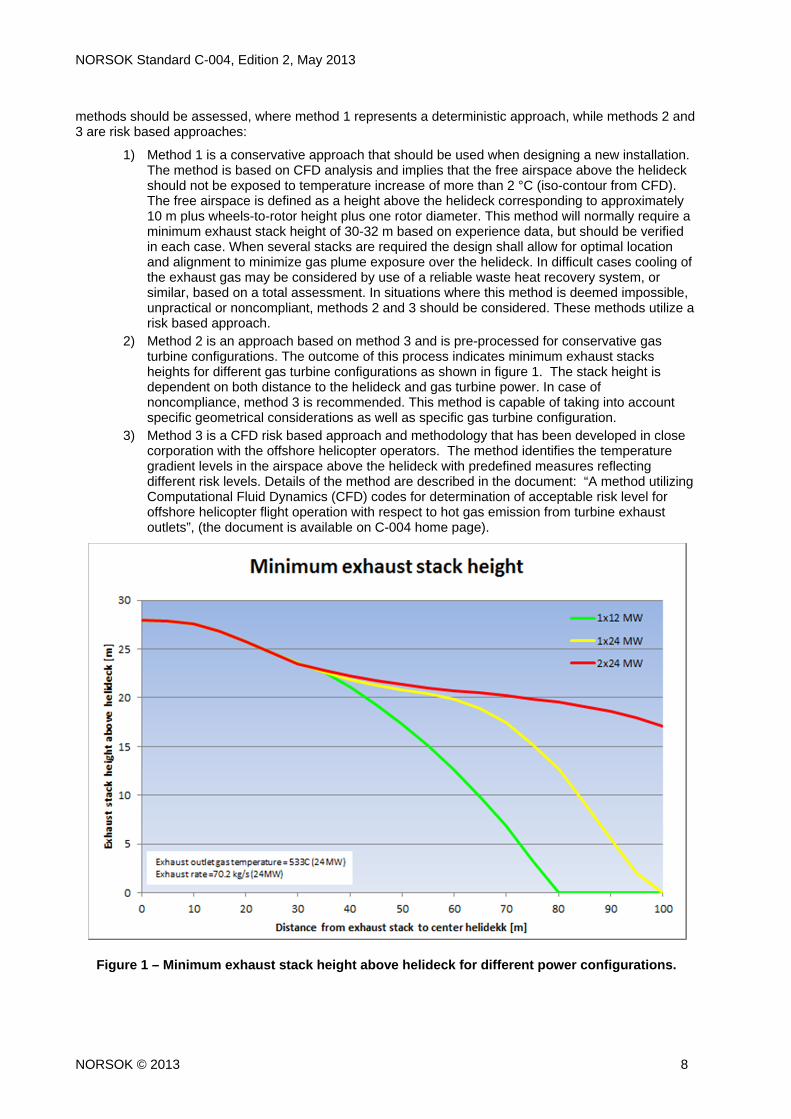
2) Method 2 is an approach based on method 3 and is pre-processed for conservative gas turbine configurations. The outcome of this process indicates minimum exhaust stacks heights for different gas turbine configurations as shown in figure 1. The stack height is dependent on both distance to the helideck and gas turbine power. In case of noncompliance, method 3 is recommended. This method is capable of taking into account specific geometrical considerations as well as specific gas turbine configuration.
3) Method 3 is a CFD risk based approach and methodology that has been developed in close corporation with the offshore helicopter operators. The method identifies the temperature gradient levels in the airspace above the helideck with predefined measures reflecting different risk levels. Details of the method are described in the document: “A method utilizing Computational Fluid Dynamics (CFD) codes for determination of acceptable risk level for offshore helicopter flight operation with respect to hot gas emission from turbine exhaust outlets”, (the document is available on C-004 home page).
Figure 1 – Minimum exhaust stack height above helideck for different power configurations.
NORSOK Standard C-004, Edition 2, May 2013
NORSOK © 2013 9
5.5 Hydrocarbon gas emission
Cold flares and emergency blow down systems are a potential source of hazard that helideck designers should be aware of. Concentration of hydrocarbon gas in the helicopter operational environment may be a potential danger to both the helicopter and the offshore installation. The helicopter itself may be a potential ignition source endangering the offshore installation; while a hydrocarbon concentration above 10 low flammability limit (LFL) may cause engine surge and flameout endangering the helicopter. Helicopter operations will immediately be stopped should such conditions occur.
5.6 Ocean waves and installations in motion
Ocean waves of a certain magnitude will normally set floating installations and vessels in motion, and the motion characteristics will vary with type of installation/vessel, operational conditions, etc. Given the movement of the installation, the calculation of the helideck movement is a simple linear transformation of roll, pitch and heave movements. The low frequency yaw, surge and sway motions should be included in the calculation of the helideck movements, when relevant. An increase in helideck height, in relation to the installation’s floatation centre, will increase the lateral movement of the helideck from roll motion.
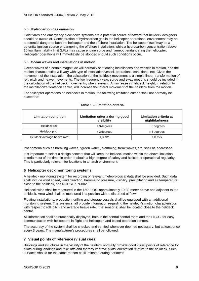
For helicopter operations on helidecks in motion, the following limitation criteria shall not normally be exceeded:
Table 1 – Limitation criteria
Limitation condition
Limitation criteria during good
visibility
Limitation criteria at
night/darkness
Helideck roll: 3 degrees 3 degrees
Helideck pitch: 3 degrees 3 degrees
Helideck average heave rate: 1,3 m/s 1,0 m/s
Phenomena such as breaking waves, “green water”, slamming, freak waves, etc. shall be addressed.
It is important to select a design concept that will keep the helideck motion within the above limitation criteria most of the time, in order to obtain a high degree of safety and helicopter operational regularity. This is particularly relevant for locations in a harsh environment.
6 Helicopter deck monitoring systems
A helideck monitoring system for recording of relevant meteorological data shall be provided. Such data shall include wind speed, wind direction, barometric pressure, visibility, precipitation and air temperature close to the helideck, see NORSOK N-002.
Helideck wind shall be measured in the 150° LOS, approximately 10-30 meter above and adjacent to the helideck. Area wind shall be measured in a position with undisturbed airflow.
Floating installations, production, drilling and storage vessels shall be equipped with an additional monitoring system. The system shall provide information regarding the helideck's motion characteristics with respect to roll, pitch and average heave rate. The sensor(s) shall be located close to the helideck centre.
All information shall be numerically displayed, both in the central control room and the HTCC, for easy communication with helicopters in flight and helicopter land based operation centres.
The accuracy of the system shall be checked and verified whenever deemed necessary, but at least once every 3 years. The manufacturer's procedures shall be followed.
7 Visual points of reference (visual cues)
Buildings and structures in the vicinity of the helideck normally provide good visual points of reference for pilots during landings and take-offs and thereby improve pilots’ orientation relative to the helideck. Such surfaces should for the same reason be illuminated during darkness.
NORSOK Standard C-004, Edition 2, May 2013
NORSOK © 2013 10
Visual points of reference on certain type of ships (e.g. FPSOs) may be severely limited in the final descent towards the helideck. This is particularly the case when the helideck is located forward, up-front of the living quarters. In such cases, necessary measures shall be taken to improve conditions, as an integral part of the forward ship design.
8 Helideck location
The helideck shall be located in a safe area on the installation. On manned installations it shall be located adjacent to or above the living quarters, when this is feasible and appropriate. Good personnel access and goods handling arrangement shall be provided to the helideck. The helideck landing surface level should be flush with the main access level to the living quarters and lift lobby whenever possible, to ease access and material handling. This may be achieved by cantilevering the helideck from a fixed deck or roof.
On production vessels, drilling vessels, and storage vessels, the helideck should preferably be located 50 % off portside and aft of mid-ship, or fully aft adjacent to portside for LQ location aft. The position shall comply with the required obstacle free sector and provide minimum displacement due to vessel movement. A forward location should be avoided, unless the LQ is located forward on the vessel.
9 Obstacle-free sector, (OFS)
The helideck shall have an obstacle-free 210° sector for take-off and landings. The point of origin of the sector shall always be at the helideck circle. It shall be marked with a black chevron, where the inside of the chevron, (facing the helideck), shall coincide with the 210° sector angle lines. No obstacles are permitted above the helideck level within this sector and outwards to a calculated safe distance based on the performance criteria of the most critical helicopter type to be used, normally 500 meters.
NOTE In certain cases there may be insufficient surface space outside the white perimeter line for painting the chevron in the correct position, as described above. In such cases the chevron may be painted with its point of origin in line with the inside edge of the white perimeter line, while the actual point of origin for the 210° OFS still remains at its correct position. Alternatively an extension plate may be provided locally outside the perimeter line for inscription of the chevron.
Exempted from the above OFS height restrictions are the following items that shall be located outside the white perimeter line, and within a height limitation of 250mm above the helideck:
safety kerb,(50 mm height);
green perimeter lights
flood lights;
foam monitors in stand-by position;
stair exit signs;
collapsible stairway handrails;
safety net outer edge, (when applicable).
No other equipment or construction shall penetrate this sector.
The bisector of the 210° OFS shall normally pass through the centre of the helideck circle. The sector may be “swung” 15° in either directions, but only when strictly necessary.
The white helideck “H” position marking shall be located in the centre of the helideck in such a way that the bisector line coincides with the centre line of the cross bar.
10 Limited obstacle sector (LOS)
The point of origin of the LOS shall coincide with that of the OFS.
The two LOS segment lines, (defined by 0,12DH and 0,33DH from the outer edge of the perimeter line), shall be parallel to the perimeter line, and follow the shape of the perimeter line within the 150° LOS. This will secure a safe distance to all obstacles within LOS for all landings on the helideck.
NOTE The segment lines will only form arcs to the helideck circle in cases where the actual perimeter of the landing area is a circle.
For obstacles in the 150° limited obstacle sector the following shall apply:
NORSOK Standard C-004, Edition 2, May 2013
NORSOK © 2013 11
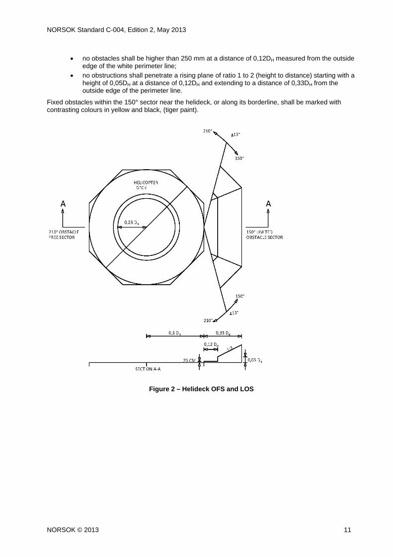
no obstacles shall be higher than 250 mm at a distance of 0,12DH measured from the outside edge of the white perimeter line;
no obstructions shall penetrate a rising plane of ratio 1 to 2 (height to distance) starting with a height of 0,05DH at a distance of 0,12DH and extending to a distance of 0,33DH from the outside edge of the perimeter line.
Fixed obstacles within the 150° sector near the helideck, or along its borderline, shall be marked with contrasting colours in yellow and black, (tiger paint).
Figure 2 – Helideck OFS and LOS
NORSOK Standard C-004, Edition 2, May 2013
NORSOK © 2013 12
11 Falling 5:1 gradient
An obstacle free airspace shall be provided below the helideck. It shall extend downwards from the top of the lowered gangway railing (or safety netting) at a falling gradient of 5:1 to the sea level, and outwards to 500 meters within the 180° horizontal sector passing through the helideck centre. The 180° sector line shall be perpendicular to the bisector of the OFS.
No objects located below the helideck shall penetrate this airspace, (e.g. lifeboats, structures, equipment, bridges, or similar).
NOTE The intention is to create safe clearance in the event of a helicopter engine failure adjacent to the helideck, where it may be necessary to descend the helicopter below the helideck level to gain sufficient speed for safe recovery, or to land on the sea if necessary.
12 Helideck design
The helideck design shall ensure sufficient space on the helideck for safe helicopter operations and associated activities and services. Factors to be considered in the design process are, as a minimum:
helicopter performance, weight and dimensional data;
space requirements for helicopter handling and control;
safety margins;
relevant environmental data;
safe approach and take-off sector;
direct approach and clear overshoot possibility whenever possible;
minimum need for sideways/backwards helicopter manoeuvring;
securing of helicopter on the deck, (tie-down points);
safe personnel movement and cargo handling,
minimum two independent emergency escape routes;
optimal rescue and fire fighting conditions;
“effective” landing area on installations/vessels in motion;
safe aircraft fuelling;
safe run-off to hangar(s) and/or parking area(s), (when applicable);
operation of large national and international rescue helicopters.
The following design criteria shall apply:
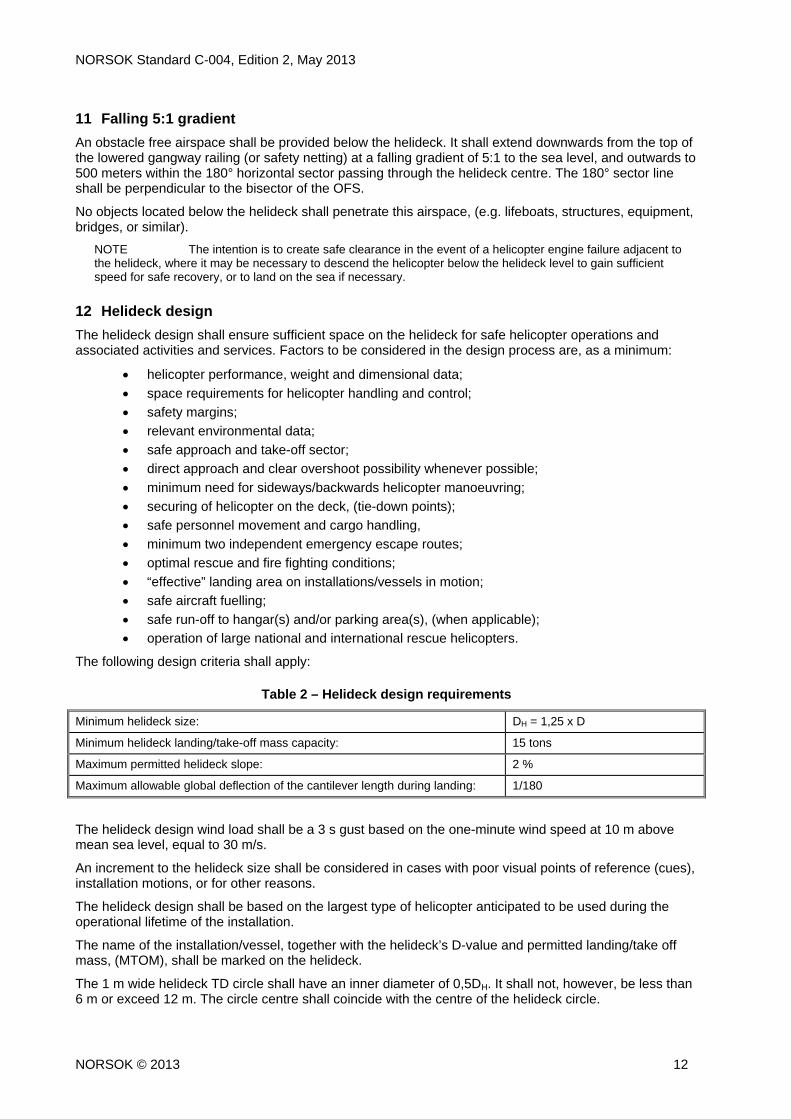
Table 2 – Helideck design requirements
The helideck design wind load shall be a 3 s gust based on the one-minute wind speed at 10 m above mean sea level, equal to 30 m/s.
An increment to the helideck size shall be considered in cases with poor visual points of reference (cues), installation motions, or for other reasons.
The helideck design shall be based on the largest type of helicopter anticipated to be used during the operational lifetime of the installation.
The name of the installation/vessel, together with the helideck’s D-value and permitted landing/take off mass, (MTOM), shall be marked on the helideck.
The 1 m wide helideck TD circle shall have an inner diameter of 0,5DH. It shall not, however, be less than 6 m or exceed 12 m. The circle centre shall coincide with the centre of the helideck circle.
Minimum helideck size: DH = 1,25 x D
Minimum helideck landing/take-off mass capacity: 15 tons
Maximum permitted helideck slope: 2 %
Maximum allowable global deflection of the cantilever length during landing: 1/180
NORSOK Standard C-004, Edition 2, May 2013
NORSOK © 2013 13
13 Helideck materials and fabrication
The complete helideck, with associated walkways, stairs, hand- and guardrails, etc., shall be of a prefabricated standardised type.
The helideck shall be of a “safe deck” type aluminium construction with a system of extruded profiles. The profile design shall allow for integration of required deck friction, recessed drainage, passive fire suppression, DIFFS, heat tracing, tie-down points and other specified requirements. The profiles may be joined together by means of tongue and groove connections, or similar approved method.
The system shall be robust, maintenance free and corrosion resistant, allowing for easy repair and replacement of parts. Extra care shall be taken to avoid hidden crevices where dirt can accumulate and cause corrosion over time.
The helideck bottom construction (underside) shall be water/fuel tight to prevent leakages to areas below, and shall be formally tested in this respect.
All materials shall be of seawater resistant aluminium alloy. Other types of materials may be considered, but are subject to operator/company approval.
The helideck support structure should preferably be constructed in sea water resistant aluminium alloy, or stainless steel, to avoid additional surface protection coating. Use of carbon steel support structure shall be subject to operator/company approval. If selected, the complete support structure shall be fully protected with thermally sprayed on aluminium coating in accordance with NORSOK M-501, system 2, unless specified otherwise. Dissimilar materials shall be galvanic protected to prevent corrosion.
Both the aluminium helideck and any aluminium support structure may be of welded or bolted construction. Bolted constructions shall have lock nuts and through bolts sufficiently dimensioned and fabricated in A4 quality. The fixing connections shall be designed to withstand all relevant vibrations and design forces.
Structural fabrication, welding and inspection shall be in accordance with EN 1090-3: Execution of steel structures and aluminium structures, Part 3: Technical requirements for aluminium structures.
The helideck support structure shall be provided with suitable vortex shedding to avoid vortex induced vibrations, unless formally documented as unnecessary.
14 Helideck surface friction
The surface of the helideck shall be permanently skid-proof in all directions, and under all conditions, for both helicopters and personnel. The surface friction shall be an integrated part of the deck structure design (serrated surface, extruded profile edges, or similar) without any additional surface treatment or coating.
The friction coefficient on a wet deck, shall be at least 0,65 in all directions between the locked helicopter wheels and the deck surface, including marked areas. The supplier of the helideck shall verify this by using a recognised test method within the industry. The test method and results shall be formally documented.
Rope nets are not required for helidecks on fixed, manned installations with movements within +/- 1°. Semi submergible installations, unmanned installations, buoy type installations and ships, such as FPSOs, storage tankers etc., shall always be equipped with rope nets.
15 Sub-zero conditions
The helideck surface friction shall not be impaired by snow, ice and frost. Helidecks exposed to sub-zero conditions, with frequent snow and ice, shall be provided with a complete and reliable deck integrated heat tracing system for de-icing of the entire landing area.
The heat tracing system shall have an appropriate response time to provide effective de-icing, inclusive drains and down-pipes. The aim shall be to bring the surface structure(s) to stabilised temperatures within one hour, which will ensure a steady state of de-icing.
It shall be possible to regulate the effect, (heat emission), at intervals to suite local conditions at any one time. This will also facilitate the possibility of having a certain effect continuously on in periods to avoid
NORSOK Standard C-004, Edition 2, May 2013
NORSOK © 2013 14
“cold start” of the system. The required de-icing effect shall be specified in each case by the operator/company in terms of W/m2.
The helideck de-icing system shall be automatically activated when the temperature drops below a given temperature, e.g. +5 °C. For energy saving purposes the control system should control the heating cables so that the heating output is proportional to the heat loss and/or ambient temperature. A manual overriding function shall permit activation or deactivation of the entire system whenever required.
The heat tracing system may be divided into appropriate sections, to allow for sequential activation. The area covering the width of the TD circle shall always be activated first.
At locations with continuous snow and ice over long periods, an effective heat tracing system shall be installed for the helideck lowered walkway, unless specified otherwise. The purpose is to keep the gangway free from ice and snow during helicopter operations to allow for safe personnel access and escape.
The systems shall be managed from the control panel in the HTCC. Buttons shall be labelled for identification, and illuminate when activated.
The systems shall be reliable, maintenance free, and protected from possible physical damage.
16 Lowered perimeter walkway/safety net
All manned installations shall be equipped with a lowered perimeter walkway around the helideck. The walkway shall be connected to the helideck stairs, and shall have no dead ends. The walkway shall function as emergency escape way in an emergency situation, when escape on the helideck itself is impossible.
A minimum of three exit stairs shall be provided from the helideck landing area and down to the lowered walkway. The exits shall be placed at an angle spacing of maximum 120° around the helideck.
One of these exits will normally be located within the 180° sector for the falling 5:1 gradient. In this case a local projection in the lowered walkway is permitted to a width of up to 3 meters from the physical edge of the helideck. The purpose is strictly to secure sufficient space for the exit stairway, any required foam monitor/rescue equipment, and access to any required emergency stairway providing access to a safe area. The infringement shall be as small as possible.
A minimum of two independent escape-ways shall be provided from the lowered perimeter walkway to safe areas. The lowered perimeter walkway shall have a free width of 1 500 mm, and its deck surface shall be approximately 1 500 mm below the level of the helideck. The walkway shall be wider near the stairs leading to the helideck, to allow for sufficient space for stairs and any monitors/rescue equipment.
The free width of the walkway may be reduced to 1200 mm in front of the stairways to comply with the 38° stairway pitch requirement.
Solid hand- and guardrails shall be provided, where the top shall be 1 400 mm above the walkway surface. Additional solid aluminium netting shall be securely attached to the inside of the guardrail to provide additional personnel protection. The free opening shall not exceed 200 mm in the horizontal direction and 100 mm in the vertical direction. The maximum distance between stanchions shall be 750 mm.
Any horizontal opening between the inner side of the walkway and the physical edge of the helideck is not permitted.
The lowered perimeter walkway surface shall consist of a fine-meshed non-skid grating or non-skid high density punctured plates/planks. The sides of the walkway shall be terminated with a solid 100 mm high toe-plate.
Normally unmanned installations may be equipped with a 1,5 m wide safety net around the helideck, if such a solution is deemed more suitable than a lowered perimeter walkway. A minimum of three independent escape ways shall be provided, at an angle spacing of maximum 120°.Two of the escape ways may be connected to a walkway underneath the helideck, providing access to a safe area.
Stair handrails to the helideck shall be of a collapsible type, which, when folded down, are no higher than 250 mm above the helideck landing surface level. The folding operation shall be simple, with quick release locking bolts, or a similar device.
NORSOK Standard C-004, Edition 2, May 2013
NORSOK © 2013 15
Reflective “EXIT” signs and arrow signs pointing to correct direction shall be positioned on the outer railing opposite the stairs from the helideck. The signs shall be positioned below the handrail and be visible from the top of the helideck stairs.
All stair treads shall have a solid toe plate of minimum 50 mm height. The design of stairs, hand- and guardrails shall otherwise comply with NORSOK C-002.
17 Fire and rescue preparedness
17.1 General
Fire-fighting and rescue equipment shall be installed in accordance with NORSOK S-001, where the requirements for the following systems are covered in detail:
deck integrated fire fighting systems (DIFFS);
foam monitor system (FMS);
dual agent hose reels;
hand operated fire-fighting extinguishers.
Relevant fire-fighting system activation buttons shall be neatly installed in the HTCC operational console. The buttons shall illuminate when activated, and be clearly labelled for identification. The buttons shall be protected from unintentional activation, and shall be controlled by two separate actions.
17.2 Helideck drainage and passive fire suppression
The entire helideck area shall be provided with a recessed drainage and passive fire suppressive system in order to ensure optimal rescue and fire fighting conditions. The system shall facilitate safe collection and discharge of fire water and any dispersed fuel to the sea or a safe area, as instructed by operator/company.
NOTE A passive fire suppressive system will not only reduce the extent of fire on the deck, but will also have a damage reducing effect in the event of a delayed DIFFS activation, or even system failure in the worst case.
The drain openings shall be densely and evenly distributed on the deck to ensure quick and effective drainage. This will also prevent pools of spilled fuel on the deck in the event of a helicopter accident scenario.
The drained liquid shall flow directly into the enclosed drain system, which may form part of the helideck profile system. The essential design requirement is that the system’s profiled shape shall have a passive fire suppressive quality that will quickly kill any burning fuel by oxygen starvation (and firewater), while also providing a certain cooling effect.
The system’s capacity shall be sufficient to safely remove all liquids resulting from continuous use of DIFFS and any FMS in combination with a major fuel spillage.
The effectiveness of the drain and fire suppressive system shall be formally documented by the helideck supplier, based on a realistic fire test scenario.
Precautions shall be taken to prevent liquids and burning fuel from flowing over the edge of helidecks in motion on vessels and floating installations.
18 Lighting
18.1 General
The helideck shall be suitably lit for operations at night and under reduced visibility conditions. The pilots shall, on approach, be able to identify the helideck and have a clear view of the helideck landing area. Structures and building surfaces around the helideck shall be illuminated to provide a good visual cueing environment for operations at night.
The helideck lighting shall consist of perimeter lights, floodlights and lowered perimeter walkway lights. All light fittings shall:
NORSOK Standard C-004, Edition 2, May 2013
NORSOK © 2013 16
have a water tight housing, being resistant to UV light, frost, sea water, fuel, oil, fire fighting liquids and liquids used for cleaning purposes, etc.;
have long lasting light sources, (LED or similar);
comply with light intensity and luminance requirement;
be practically maintenance free;
be vibration and impact resistant;
be none-dazzling to pilots and helideck crew;
have response time of approximately 1 s;
have minimum protection grade IP 66;
be certified for use in zone 1 according to the ATEX directive. The light fittings shall be delivered and installed complete with all necessary accessories, switches and fittings, ready for use.
All helideck lighting shall be controlled from HTCC. Light operating buttons shall be neatly installed in the HTCC operational console, ready for use. The buttons shall illuminate when activated, and be labelled for identification.
Helideck perimeter light and flood lights shall be connected to the emergency power system and UPS.
Helideck lighting on normally unmanned installation shall be remotely controlled from a manned installation.
It shall be verified that light fittings near the helideck area do not generate radio noise that may interfere with helicopter radio communication systems.
The type of light sources selected shall be among the best available at the time of acquisition.
18.2 Perimeter lights
The helideck shall be equipped with omnidirectional green perimeter lights that are visible from and above the helideck landing area. The lights shall have correct intensity, colour and chromaticity as defined in ICAO Annex 14.
The perimeter lights shall be located outside the white perimeter line, and be evenly spaced at maximum intervals of up to 3 meters. A perimeter light shall be placed at each corner, when feasible, in cases where the white perimeter line makes a 90° change of direction, (e.g. square or rectangular shape), to provide proper delineation of the landing area at night.
Flush mounted or recessed perimeter lights shall be installed where the perimeter line crosses the helicopter run-off to hangar and parking area or at access ways for personnel and cargo handling. The height of the light fitting shall not exceed 25 mm above the deck. It shall be slightly inclined at edges to prevent personnel from stumbling, and shall withstand a 5 ton point load from a helicopter wheel.
18.3 Flood lights
The helicopter landing area shall be illuminated for night use. A deck level flood light system shall be provided around the deck for even illumination of the entire landing area. The light fittings shall be placed outside the white perimeter line, where the light fitting front may be in line with the outside edge of the white perimeter line.
The flood light fitting shall not reduce the visual cuing of the perimeter lights, or cause glare or loss of pilots’ vision during hover and landing.
The average illumination of the landing area shall be at least 10 lux, with a ratio between average and minimum illumination of not more than 8:1. The deck illumination shall be documented by calculations and/or visual computer simulations.
The light fitting height and depth shall not exceed 250 mm.
18.4 Illumination of lowered perimeter walkway
The lowered perimeter walkway surrounding the helideck shall be illuminated to ensure safe personnel access and orientation. This requirement also applies for any other walkway connected to the helideck.
NORSOK Standard C-004, Edition 2, May 2013
NORSOK © 2013 17
Screened light fittings should preferably be located on the helideck side of the walkway, where the vertical light angle shall be well below the top of the outside handrail on the walkway.
Any fittings mounted on guardrails shall not protrude into the walkway area. The additional weight impact shall be verified by structural calculations in accordance with NORSOK C-002, section 6.
18.5 Windsock (wind direction indicator)
The required windsock(s) shall be suitably sized, correctly positioned and illuminated at night by a light fixture placed inside the windsock(s). The flight crew shall be able to see it from the entire approach sector, and from the take-off position on the helideck.
18.6 Warning lights, etc.
Red warning lights for obstructions, etc. shall be provided in accordance with the regulation in force.
The highest point of the derrick, crane boom, crane cabin and other fixed obstacles on the installation, which may represent a hazard to flying, shall be marked with red LED warning lights, or similar, suitable for NVG use. The lights shall be visible from all directions.
The derrick, crane boom and similar structures shall be fitted with red warning lights on every third part of the obstruction's total height, visible from all directions.
Obstacles may also be illuminated to improve their visibility. The flare tower and obstacles in close proximity to the helideck shall always be illuminated, without dazzling the helicopter pilots.
19 Cargo handling
A level personnel access and cargo transport route shall be provided between the helideck and the LQ entrance point(s), unless deemed strictly impossible due to severe design constraints.
Cargo shall be transported in cargo trolleys suitable for the purpose. The loading level shall be flush with the helicopter cargo door threshold, unless specified otherwise. A sheltered or indoor parking space shall be provided for the trolleys when not in use.
An external lift, lifting table, or similar device, shall be provided for safe goods handling if the helideck and the LQ entrance point(s) are at different levels. The device shall in its upper position be flush with the helideck level, and in its lower position be flush with the cargo handling level. A ramp lip shall be provided if the lower position cannot be flush with the deck. The maximum slope shall be 1:10, to facilitate use of cargo trolleys. The device shall accommodate minimum one cargo trolley, and prevent cargo from falling off.
20 Tie-down points
The helideck and any helicopter parking area shall be fitted with necessary recessed tie-down points for securing of helicopters.
21 Auxiliary equipment
Auxiliary equipment shall as far as possible be located within the 150° LOS, and shall not interfere with OFS or escape paths.
The helideck area shall be equipped with necessary electrical connection points with required EX and IP grades.
A utility station containing electrical sockets and heat traced fresh water tap, shall be provided near the helideck. A high-pressure fresh water connection point shall also be provided, when the installation is equipped with a high-pressure fresh water system. Necessary hose(s) on reel(s) shall be included for cleaning of the entire helideck. Whenever a high-pressure system is not available, an appropriate mobile unit, with necessary accessories, shall be provided for the same purpose.
All hand tools and equipment shall be stored in a sheltered, non-humid area. Protective clothing shall be stored inside the LQ in compliance with HLO requirements.
A system for removal of bird guano from the helideck is recommended for normally unmanned installations.
NORSOK Standard C-004, Edition 2, May 2013
NORSOK © 2013 18
22 Access by installation crane
The helideck and run-off area should be within the reach of one of the installation cranes whenever possible to facilitate removal of an unserviceable helicopter from the installation to a barge. The crane’s lifting capacity should be at least 8 tons.
23 Marking
The edges of all coloured (non-black) marking and lettering on the helideck shall be provided with an even 30 mm black stripe to improve readability from the air.
24 Signs
All safety and information signs related to the helideck, helideck equipment, and helideck operations, shall be strictly in accordance with BSL D 5-1 requirements.
25 Inspection and maintenance access
Access to instruments, valves and equipment for operations and maintenance shall be in accordance with NORSOK S-002. All equipment to be regularly maintained shall be easily accessible.
An inspection/maintenance access system shall be provided under the portion of the helideck inaccessible from decks and gangways.