Centrifugal Compressor - Wikipedia, The Free Encyclopedia
22
9/6/2015 Centrifugal compressor Wikipedia, the free encyclopedia https://en.wikipedia.org/wiki/Centrifugal_compressor 1/22 Centrifugal impeller with a highly polished surface likely to improve performance Jet engine cutaway showing the centrifugal compressor and other parts Centrifugal compressor From Wikipedia, the free encyclopedia Centrifugal compressors, sometimes termed radial compressors, are a subclass of dynamic axisymmetric workabsorbing turbomachinery. [1] The idealized compressive dynamic turbomachine achieves a pressure rise by adding kinetic energy/velocity to a continuous flow of fluid through the rotor or impeller. This kinetic energy is then converted to an increase in potential energy/static pressure by slowing the flow through a diffuser. The pressure rise in impeller is in most cases almost equal to the rise in the diffuser section. Contents 1 Theory of operation 2 Historical contributions, the pioneers 2.1 Partial timeline 3 Turbomachinery similarities 3.1 Turbomachinery using centrifugal compressors 4 Components of a simple centrifugal compressor 4.1 Inlet 4.2 Centrifugal impeller 4.3 Diffuser 4.4 Collector 5 Applications 6 Performance 6.1 Performance maps 6.2 Surge 6.3 Maximum flow line versus choke 6.4 Other operating limits 7 Dimensional analysis 7.1 Π theorem 7.2 Classic turbomachinery similitude 7.3 Other dimensionless combinations 7.4 Affinity laws 8 Aerothermodynamic fundamentals 8.1 Conservation of mass 8.2 Conservation of momentum 8.3 Conservation of energy 8.4 Equation of state 9 Pros and cons 10 Aerodynamic design methodology 11 Structural mechanics, manufacture and design compromise 12 See also 13 References
description
good
Transcript of Centrifugal Compressor - Wikipedia, The Free Encyclopedia
9/6/2015 Centrifugal compressor Wikipedia, the free encyclopedia
https://en.wikipedia.org/wiki/Centrifugal_compressor 1/22
Centrifugal impeller with a highlypolished surface likely to improveperformance
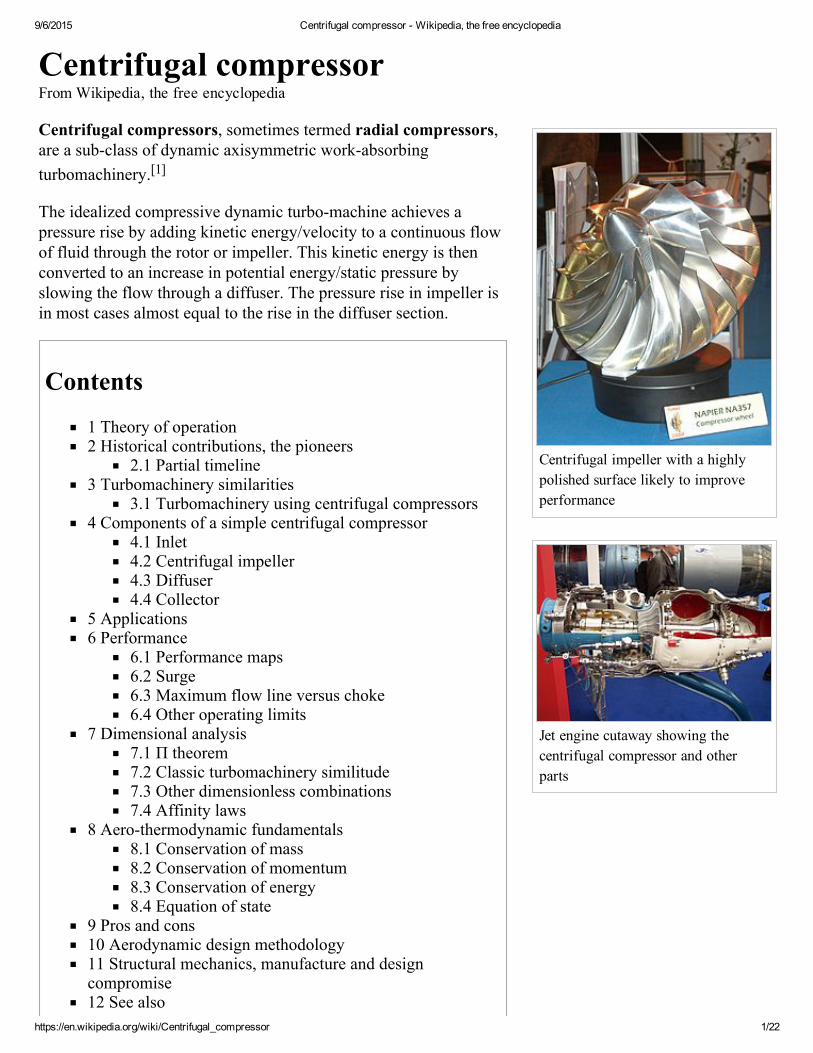
Jet engine cutaway showing thecentrifugal compressor and otherparts
Centrifugal compressorFrom Wikipedia, the free encyclopedia
Centrifugal compressors, sometimes termed radial compressors,are a subclass of dynamic axisymmetric workabsorbingturbomachinery.[1]
The idealized compressive dynamic turbomachine achieves apressure rise by adding kinetic energy/velocity to a continuous flowof fluid through the rotor or impeller. This kinetic energy is thenconverted to an increase in potential energy/static pressure byslowing the flow through a diffuser. The pressure rise in impeller isin most cases almost equal to the rise in the diffuser section.
Contents
1 Theory of operation2 Historical contributions, the pioneers
2.1 Partial timeline3 Turbomachinery similarities
3.1 Turbomachinery using centrifugal compressors4 Components of a simple centrifugal compressor
4.1 Inlet4.2 Centrifugal impeller4.3 Diffuser4.4 Collector
5 Applications6 Performance
6.1 Performance maps6.2 Surge6.3 Maximum flow line versus choke6.4 Other operating limits
7 Dimensional analysis7.1 Π theorem7.2 Classic turbomachinery similitude7.3 Other dimensionless combinations7.4 Affinity laws
8 Aerothermodynamic fundamentals8.1 Conservation of mass8.2 Conservation of momentum8.3 Conservation of energy8.4 Equation of state
9 Pros and cons10 Aerodynamic design methodology11 Structural mechanics, manufacture and designcompromise12 See also13 References
9/6/2015 Centrifugal compressor Wikipedia, the free encyclopedia
https://en.wikipedia.org/wiki/Centrifugal_compressor 2/22
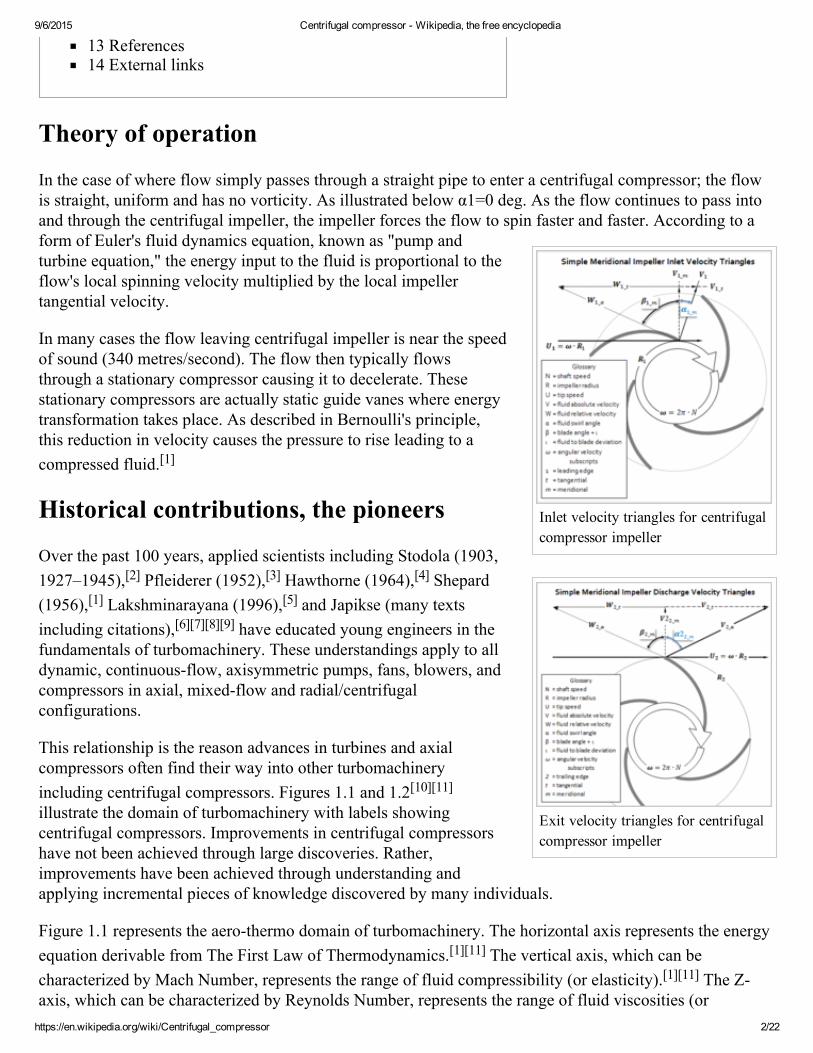
Inlet velocity triangles for centrifugalcompressor impeller
Exit velocity triangles for centrifugalcompressor impeller
13 References14 External links
Theory of operation
In the case of where flow simply passes through a straight pipe to enter a centrifugal compressor; the flowis straight, uniform and has no vorticity. As illustrated below α1=0 deg. As the flow continues to pass intoand through the centrifugal impeller, the impeller forces the flow to spin faster and faster. According to aform of Euler's fluid dynamics equation, known as "pump andturbine equation," the energy input to the fluid is proportional to theflow's local spinning velocity multiplied by the local impellertangential velocity.
In many cases the flow leaving centrifugal impeller is near the speedof sound (340 metres/second). The flow then typically flowsthrough a stationary compressor causing it to decelerate. Thesestationary compressors are actually static guide vanes where energytransformation takes place. As described in Bernoulli's principle,this reduction in velocity causes the pressure to rise leading to acompressed fluid.[1]
Historical contributions, the pioneers
Over the past 100 years, applied scientists including Stodola (1903,1927–1945),[2] Pfleiderer (1952),[3] Hawthorne (1964),[4] Shepard(1956),[1] Lakshminarayana (1996),[5] and Japikse (many textsincluding citations),[6][7][8][9] have educated young engineers in thefundamentals of turbomachinery. These understandings apply to alldynamic, continuousflow, axisymmetric pumps, fans, blowers, andcompressors in axial, mixedflow and radial/centrifugalconfigurations.
This relationship is the reason advances in turbines and axialcompressors often find their way into other turbomachineryincluding centrifugal compressors. Figures 1.1 and 1.2[10][11]illustrate the domain of turbomachinery with labels showingcentrifugal compressors. Improvements in centrifugal compressorshave not been achieved through large discoveries. Rather,improvements have been achieved through understanding andapplying incremental pieces of knowledge discovered by many individuals.
Figure 1.1 represents the aerothermo domain of turbomachinery. The horizontal axis represents the energyequation derivable from The First Law of Thermodynamics.[1][11] The vertical axis, which can becharacterized by Mach Number, represents the range of fluid compressibility (or elasticity).[1][11] The Zaxis, which can be characterized by Reynolds Number, represents the range of fluid viscosities (or
9/6/2015 Centrifugal compressor Wikipedia, the free encyclopedia
https://en.wikipedia.org/wiki/Centrifugal_compressor 3/22
Figure 1.1 – Aerothermo domain ofturbomachinery
Figure 1.2 – Physical domain ofturbomachinery
stickiness).[1][11] Mathematicians and Physicists who established the foundations of this aerothermodomain include:[12][13] Sir Isaac Newton, Daniel Bernoulli, Leonhard Euler, ClaudeLouis Navier, SirGeorge Gabriel Stokes, Ernst Mach, Nikolay Yegorovich Zhukovsky, Martin Wilhelm Kutta, LudwigPrandtl, Theodore von Kármán, Paul Richard Heinrich Blasius, and Henri Coandă.
Figure 1.2 represents the physical or mechanical domain of turbomachinery. Again, the horizontal axisrepresents the energy equation with turbines generating power to theleft and compressors absorbing power to the right.[1][11] Within thephysical domain the vertical axis differentiates between high speedsand low speeds depending upon the turbomachineryapplication.[1][11] The Zaxis differentiates between axialflowgeometry and radialflow geometry within the physical domain ofturbomachinery.[1][11] It is implied that mixedflow turbomachinerylie between axial and radial.[1][11] Key contributors of technicalachievements that pushed the practical application ofturbomachinery forward include:[12][13] Denis Papin,[14] KernelienLe Demour, Daniel Gabriel Fahrenheit, John Smeaton, Dr. A. C. E.Rateau,[15] John Barber, Alexander Sablukov, Sir Charles AlgernonParsons, Ægidius Elling, Sanford Alexander Moss, Willis Carrier,Adolf Busemann, Hermann Schlichting, Frank Whittle and Hansvon Ohain.
Partial timeline
<1689 Early turbomachines Pumps, blowers, fans
1689 Denis Papin Origin of the centrifugalcompressor
1754 Leonhard Euler Euler's "Pump & Turbine"equation
1791 John Barber First gas turbine patent
1899 Dr. A. C. E. Rateau First practical centrifugalcompressor
1927 Aurel Boleslav Stodola Formalized "slip factor"1928 Adolf Busemann Derived "slip factor"
1937Frank Whittle andHans von Ohain,independently
First gas turbine using centrifugalcompressor
>1970 Modern turbomachines3DCFD, rocket turbopumps,heart assist pumps, turbochargedfuel cells
Turbomachinery similarities
9/6/2015 Centrifugal compressor Wikipedia, the free encyclopedia
https://en.wikipedia.org/wiki/Centrifugal_compressor 4/22
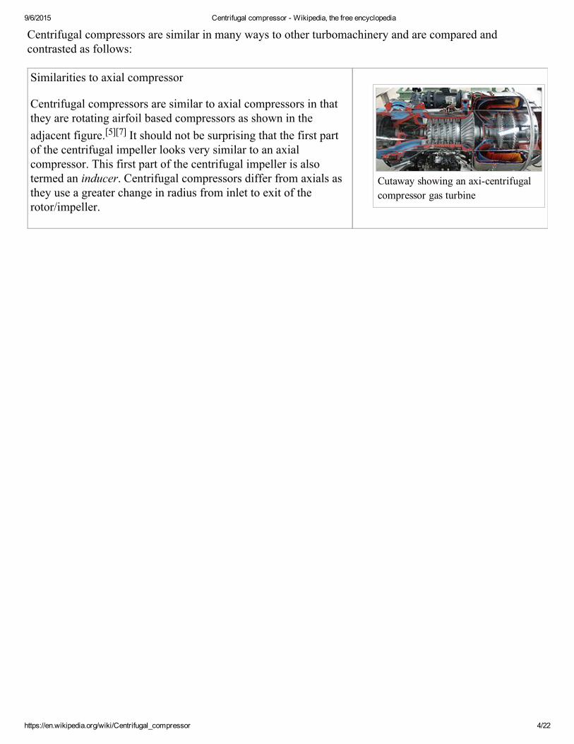
Cutaway showing an axicentrifugalcompressor gas turbine
Centrifugal compressors are similar in many ways to other turbomachinery and are compared andcontrasted as follows:
Similarities to axial compressor
Centrifugal compressors are similar to axial compressors in thatthey are rotating airfoil based compressors as shown in theadjacent figure.[5][7] It should not be surprising that the first partof the centrifugal impeller looks very similar to an axialcompressor. This first part of the centrifugal impeller is alsotermed an inducer. Centrifugal compressors differ from axials asthey use a greater change in radius from inlet to exit of therotor/impeller.
9/6/2015 Centrifugal compressor Wikipedia, the free encyclopedia
https://en.wikipedia.org/wiki/Centrifugal_compressor 5/22
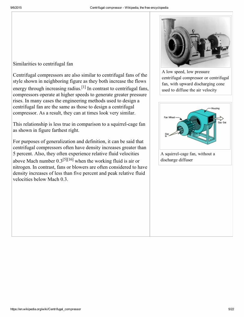
A low speed, low pressurecentrifugal compressor or centrifugalfan, with upward discharging coneused to diffuse the air velocity
A squirrelcage fan, without adischarge diffuser
Similarities to centrifugal fan
Centrifugal compressors are also similar to centrifugal fans of thestyle shown in neighboring figure as they both increase the flowsenergy through increasing radius.[1] In contrast to centrifugal fans,compressors operate at higher speeds to generate greater pressurerises. In many cases the engineering methods used to design acentrifugal fan are the same as those to design a centrifugalcompressor. As a result, they can at times look very similar.
This relationship is less true in comparison to a squirrelcage fanas shown in figure farthest right.
For purposes of generalization and definition, it can be said thatcentrifugal compressors often have density increases greater than5 percent. Also, they often experience relative fluid velocitiesabove Mach number 0.3[5][16] when the working fluid is air ornitrogen. In contrast, fans or blowers are often considered to havedensity increases of less than five percent and peak relative fluidvelocities below Mach 0.3.
9/6/2015 Centrifugal compressor Wikipedia, the free encyclopedia
https://en.wikipedia.org/wiki/Centrifugal_compressor 6/22
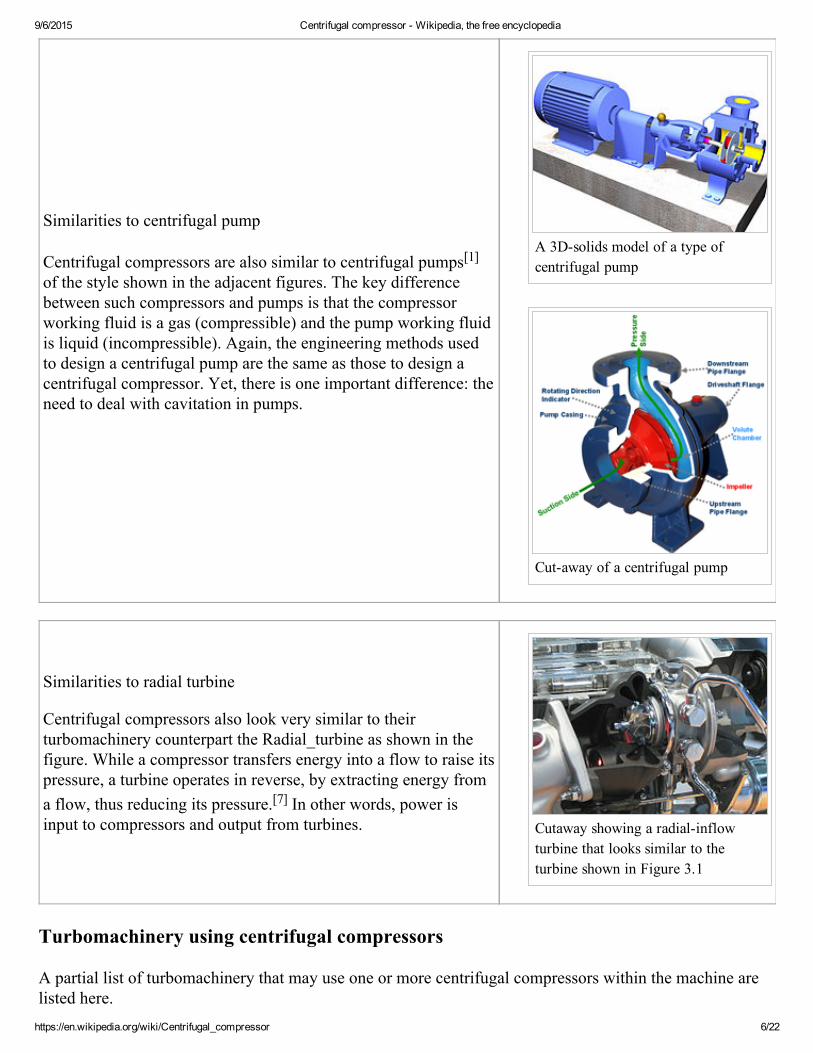
A 3Dsolids model of a type ofcentrifugal pump
Cutaway of a centrifugal pump
Cutaway showing a radialinflowturbine that looks similar to theturbine shown in Figure 3.1
Similarities to centrifugal pump
Centrifugal compressors are also similar to centrifugal pumps[1]of the style shown in the adjacent figures. The key differencebetween such compressors and pumps is that the compressorworking fluid is a gas (compressible) and the pump working fluidis liquid (incompressible). Again, the engineering methods usedto design a centrifugal pump are the same as those to design acentrifugal compressor. Yet, there is one important difference: theneed to deal with cavitation in pumps.
Similarities to radial turbine
Centrifugal compressors also look very similar to theirturbomachinery counterpart the Radial_turbine as shown in thefigure. While a compressor transfers energy into a flow to raise itspressure, a turbine operates in reverse, by extracting energy froma flow, thus reducing its pressure.[7] In other words, power isinput to compressors and output from turbines.
Turbomachinery using centrifugal compressors
A partial list of turbomachinery that may use one or more centrifugal compressors within the machine arelisted here.
9/6/2015 Centrifugal compressor Wikipedia, the free encyclopedia
https://en.wikipedia.org/wiki/Centrifugal_compressor 7/22
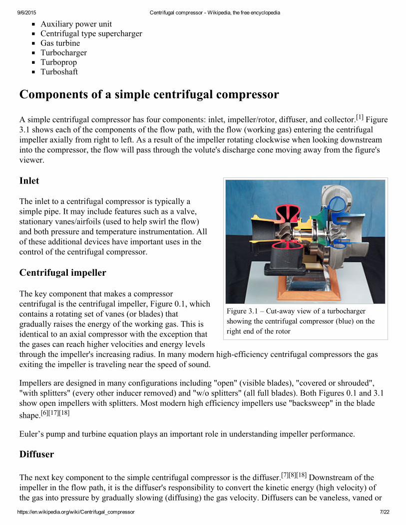
Figure 3.1 – Cutaway view of a turbochargershowing the centrifugal compressor (blue) on theright end of the rotor
Auxiliary power unitCentrifugal type superchargerGas turbineTurbochargerTurbopropTurboshaft
Components of a simple centrifugal compressor
A simple centrifugal compressor has four components: inlet, impeller/rotor, diffuser, and collector.[1] Figure3.1 shows each of the components of the flow path, with the flow (working gas) entering the centrifugalimpeller axially from right to left. As a result of the impeller rotating clockwise when looking downstreaminto the compressor, the flow will pass through the volute's discharge cone moving away from the figure'sviewer.
Inlet
The inlet to a centrifugal compressor is typically asimple pipe. It may include features such as a valve,stationary vanes/airfoils (used to help swirl the flow)and both pressure and temperature instrumentation. Allof these additional devices have important uses in thecontrol of the centrifugal compressor.
Centrifugal impeller
The key component that makes a compressorcentrifugal is the centrifugal impeller, Figure 0.1, whichcontains a rotating set of vanes (or blades) thatgradually raises the energy of the working gas. This isidentical to an axial compressor with the exception thatthe gases can reach higher velocities and energy levelsthrough the impeller's increasing radius. In many modern highefficiency centrifugal compressors the gasexiting the impeller is traveling near the speed of sound.
Impellers are designed in many configurations including "open" (visible blades), "covered or shrouded","with splitters" (every other inducer removed) and "w/o splitters" (all full blades). Both Figures 0.1 and 3.1show open impellers with splitters. Most modern high efficiency impellers use "backsweep" in the bladeshape.[6][17][18]
Euler’s pump and turbine equation plays an important role in understanding impeller performance.
Diffuser
The next key component to the simple centrifugal compressor is the diffuser.[7][8][18] Downstream of theimpeller in the flow path, it is the diffuser's responsibility to convert the kinetic energy (high velocity) ofthe gas into pressure by gradually slowing (diffusing) the gas velocity. Diffusers can be vaneless, vaned or
9/6/2015 Centrifugal compressor Wikipedia, the free encyclopedia
https://en.wikipedia.org/wiki/Centrifugal_compressor 8/22
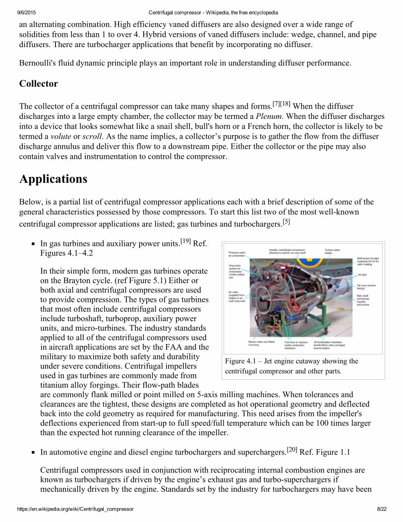
Figure 4.1 – Jet engine cutaway showing thecentrifugal compressor and other parts.
an alternating combination. High efficiency vaned diffusers are also designed over a wide range ofsolidities from less than 1 to over 4. Hybrid versions of vaned diffusers include: wedge, channel, and pipediffusers. There are turbocharger applications that benefit by incorporating no diffuser.
Bernoulli's fluid dynamic principle plays an important role in understanding diffuser performance.
Collector
The collector of a centrifugal compressor can take many shapes and forms.[7][18] When the diffuserdischarges into a large empty chamber, the collector may be termed a Plenum. When the diffuser dischargesinto a device that looks somewhat like a snail shell, bull's horn or a French horn, the collector is likely to betermed a volute or scroll. As the name implies, a collector’s purpose is to gather the flow from the diffuserdischarge annulus and deliver this flow to a downstream pipe. Either the collector or the pipe may alsocontain valves and instrumentation to control the compressor.
Applications
Below, is a partial list of centrifugal compressor applications each with a brief description of some of thegeneral characteristics possessed by those compressors. To start this list two of the most wellknowncentrifugal compressor applications are listed; gas turbines and turbochargers.[5]
In gas turbines and auxiliary power units.[19] Ref.Figures 4.1–4.2
In their simple form, modern gas turbines operateon the Brayton cycle. (ref Figure 5.1) Either orboth axial and centrifugal compressors are usedto provide compression. The types of gas turbinesthat most often include centrifugal compressorsinclude turboshaft, turboprop, auxiliary powerunits, and microturbines. The industry standardsapplied to all of the centrifugal compressors usedin aircraft applications are set by the FAA and themilitary to maximize both safety and durabilityunder severe conditions. Centrifugal impellersused in gas turbines are commonly made fromtitanium alloy forgings. Their flowpath bladesare commonly flank milled or point milled on 5axis milling machines. When tolerances andclearances are the tightest, these designs are completed as hot operational geometry and deflectedback into the cold geometry as required for manufacturing. This need arises from the impeller'sdeflections experienced from startup to full speed/full temperature which can be 100 times largerthan the expected hot running clearance of the impeller.
In automotive engine and diesel engine turbochargers and superchargers.[20] Ref. Figure 1.1
Centrifugal compressors used in conjunction with reciprocating internal combustion engines areknown as turbochargers if driven by the engine’s exhaust gas and turbosuperchargers ifmechanically driven by the engine. Standards set by the industry for turbochargers may have been
9/6/2015 Centrifugal compressor Wikipedia, the free encyclopedia
https://en.wikipedia.org/wiki/Centrifugal_compressor 9/22
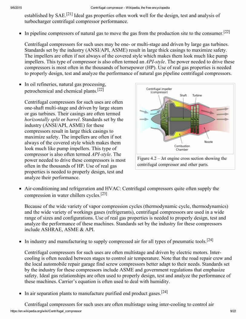
Figure 4.2 – Jet engine cross section showing thecentrifugal compressor and other parts.
established by SAE.[21] Ideal gas properties often work well for the design, test and analysis ofturbocharger centrifugal compressor performance.
In pipeline compressors of natural gas to move the gas from the production site to the consumer.[22]
Centrifugal compressors for such uses may be one or multistage and driven by large gas turbines.Standards set by the industry (ANSI/API, ASME) result in large thick casings to maximize safety.The impellers are often if not always of the covered style which makes them look much like pumpimpellers. This type of compressor is also often termed an APIstyle. The power needed to drive thesecompressors is most often in the thousands of horsepower (HP). Use of real gas properties is neededto properly design, test and analyze the performance of natural gas pipeline centrifugal compressors.
In oil refineries, natural gas processing,petrochemical and chemical plants.[22]
Centrifugal compressors for such uses are oftenoneshaft multistage and driven by large steamor gas turbines. Their casings are often termedhorizontally split or barrel. Standards set by theindustry (ANSI/API, ASME) for thesecompressors result in large thick casings tomaximize safety. The impellers are often if notalways of the covered style which makes themlook much like pump impellers. This type ofcompressor is also often termed APIstyle. Thepower needed to drive these compressors is mostoften in the thousands of HP. Use of real gasproperties is needed to properly design, test andanalyze their performance.
Airconditioning and refrigeration and HVAC: Centrifugal compressors quite often supply thecompression in water chillers cycles.[23]
Because of the wide variety of vapor compression cycles (thermodynamic cycle, thermodynamics)and the wide variety of workings gases (refrigerants), centrifugal compressors are used in a widerange of sizes and configurations. Use of real gas properties is needed to properly design, test andanalyze the performance of these machines. Standards set by the industry for these compressorsinclude ASHRAE, ASME & API.
In industry and manufacturing to supply compressed air for all types of pneumatic tools.[24]
Centrifugal compressors for such uses are often multistage and driven by electric motors. Intercooling is often needed between stages to control air temperature. Note that the road repair crew andthe local automobile repair garage find screw compressors better adapt to their needs. Standards setby the industry for these compressors include ASME and government regulations that emphasizesafety. Ideal gas relationships are often used to properly design, test and analyze the performance ofthese machines. Carrier’s equation is often used to deal with humidity.
In air separation plants to manufacture purified end product gases.[24]
Centrifugal compressors for such uses are often multistage using intercooling to control air
9/6/2015 Centrifugal compressor Wikipedia, the free encyclopedia
https://en.wikipedia.org/wiki/Centrifugal_compressor 10/22
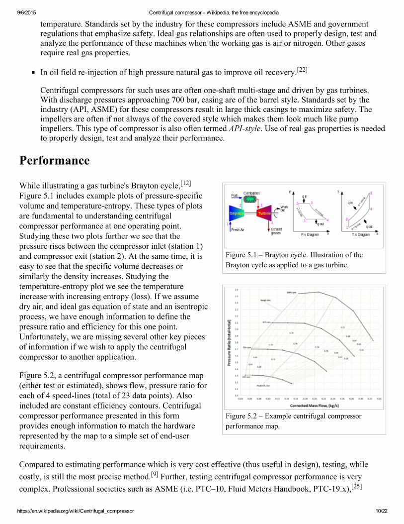
Figure 5.1 – Brayton cycle. Illustration of theBrayton cycle as applied to a gas turbine.
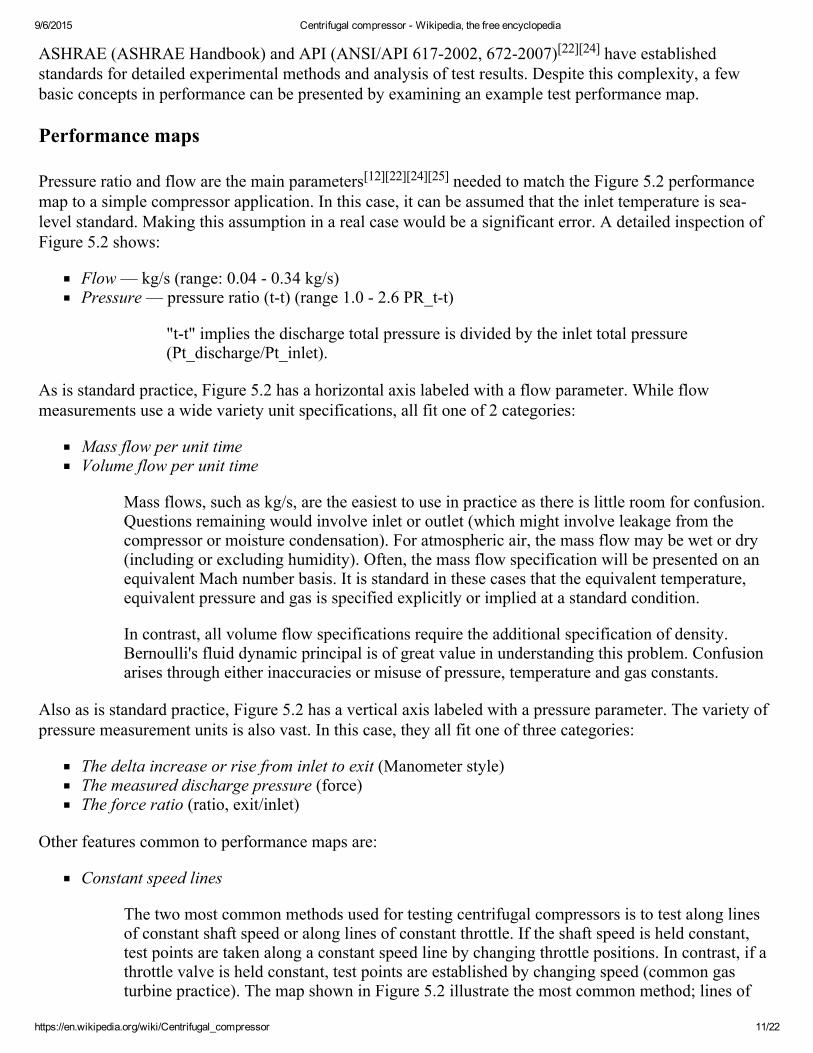
Figure 5.2 – Example centrifugal compressorperformance map.
temperature. Standards set by the industry for these compressors include ASME and governmentregulations that emphasize safety. Ideal gas relationships are often used to properly design, test andanalyze the performance of these machines when the working gas is air or nitrogen. Other gasesrequire real gas properties.
In oil field reinjection of high pressure natural gas to improve oil recovery.[22]
Centrifugal compressors for such uses are often oneshaft multistage and driven by gas turbines.With discharge pressures approaching 700 bar, casing are of the barrel style. Standards set by theindustry (API, ASME) for these compressors result in large thick casings to maximize safety. Theimpellers are often if not always of the covered style which makes them look much like pumpimpellers. This type of compressor is also often termed APIstyle. Use of real gas properties is neededto properly design, test and analyze their performance.
Performance
While illustrating a gas turbine's Brayton cycle,[12]Figure 5.1 includes example plots of pressurespecificvolume and temperatureentropy. These types of plotsare fundamental to understanding centrifugalcompressor performance at one operating point.Studying these two plots further we see that thepressure rises between the compressor inlet (station 1)and compressor exit (station 2). At the same time, it iseasy to see that the specific volume decreases orsimilarly the density increases. Studying thetemperatureentropy plot we see the temperatureincrease with increasing entropy (loss). If we assumedry air, and ideal gas equation of state and an isentropicprocess, we have enough information to define thepressure ratio and efficiency for this one point.Unfortunately, we are missing several other key piecesof information if we wish to apply the centrifugalcompressor to another application.
Figure 5.2, a centrifugal compressor performance map(either test or estimated), shows flow, pressure ratio foreach of 4 speedlines (total of 23 data points). Alsoincluded are constant efficiency contours. Centrifugalcompressor performance presented in this formprovides enough information to match the hardwarerepresented by the map to a simple set of enduserrequirements.
Compared to estimating performance which is very cost effective (thus useful in design), testing, whilecostly, is still the most precise method.[9] Further, testing centrifugal compressor performance is verycomplex. Professional societies such as ASME (i.e. PTC–10, Fluid Meters Handbook, PTC19.x),[25]
9/6/2015 Centrifugal compressor Wikipedia, the free encyclopedia
https://en.wikipedia.org/wiki/Centrifugal_compressor 11/22
ASHRAE (ASHRAE Handbook) and API (ANSI/API 6172002, 6722007)[22][24] have establishedstandards for detailed experimental methods and analysis of test results. Despite this complexity, a fewbasic concepts in performance can be presented by examining an example test performance map.
Performance maps
Pressure ratio and flow are the main parameters[12][22][24][25] needed to match the Figure 5.2 performancemap to a simple compressor application. In this case, it can be assumed that the inlet temperature is sealevel standard. Making this assumption in a real case would be a significant error. A detailed inspection ofFigure 5.2 shows:
Flow — kg/s (range: 0.04 0.34 kg/s)Pressure — pressure ratio (tt) (range 1.0 2.6 PR_tt)
"tt" implies the discharge total pressure is divided by the inlet total pressure(Pt_discharge/Pt_inlet).
As is standard practice, Figure 5.2 has a horizontal axis labeled with a flow parameter. While flowmeasurements use a wide variety unit specifications, all fit one of 2 categories:
Mass flow per unit timeVolume flow per unit time
Mass flows, such as kg/s, are the easiest to use in practice as there is little room for confusion.Questions remaining would involve inlet or outlet (which might involve leakage from thecompressor or moisture condensation). For atmospheric air, the mass flow may be wet or dry(including or excluding humidity). Often, the mass flow specification will be presented on anequivalent Mach number basis. It is standard in these cases that the equivalent temperature,equivalent pressure and gas is specified explicitly or implied at a standard condition.
In contrast, all volume flow specifications require the additional specification of density.Bernoulli's fluid dynamic principal is of great value in understanding this problem. Confusionarises through either inaccuracies or misuse of pressure, temperature and gas constants.
Also as is standard practice, Figure 5.2 has a vertical axis labeled with a pressure parameter. The variety ofpressure measurement units is also vast. In this case, they all fit one of three categories:
The delta increase or rise from inlet to exit (Manometer style)The measured discharge pressure (force)The force ratio (ratio, exit/inlet)
Other features common to performance maps are:
Constant speed lines
The two most common methods used for testing centrifugal compressors is to test along linesof constant shaft speed or along lines of constant throttle. If the shaft speed is held constant,test points are taken along a constant speed line by changing throttle positions. In contrast, if athrottle valve is held constant, test points are established by changing speed (common gasturbine practice). The map shown in Figure 5.2 illustrate the most common method; lines of
9/6/2015 Centrifugal compressor Wikipedia, the free encyclopedia
https://en.wikipedia.org/wiki/Centrifugal_compressor 12/22
constant speed. In this case we see data points connected via straight lines at speeds of 50%,71%, 87%, and 100% RPM. The first three speed lines have 6 points each while the highestspeed line has five.
Constant efficiency islands
The next feature to be discussed is the oval shaped curves representing islands of constantefficiency. In this figure we see 11 contours ranging from 56% efficiency (decimal 0.56) to76% efficiency (decimal 0.76). General standard practice is to interpret these efficiencies asisentropic rather than polytropic. The inclusion of efficiency islands effectively generates a 3dimensional topology to this 2dimensional map. With inlet density specified, it provides afurther ability to calculate aerodynamic power. Lines of constant power could just as easily besubstituted.
Design point(s) or guarantee point(s)
Regarding gas turbine operation and performance, there may be a series of guaranteed pointsestablished for the gas turbine’s centrifugal compressor. These requirements are of secondaryimportance to the overall gas turbine performance as a whole. For this reason it is onlynecessary to summarize that in the ideal case, the lowest specific fuel consumption wouldoccur when the centrifugal compressors peak efficiency curve coincides with the gas turbine'srequired operation line.
In contrast to gas turbines, most other applications (including industrial) need to meet a lessstringent set of performance requirements. Historically, centrifugal compressors applied toindustrial applications were needed to achieve performance at a specific flow and pressure.Modern industrial compressors are often needed to achieve specific performance goals across arange of flows and pressures; thus taking a significant step toward the sophistication seen ingas turbine applications.
If the compressor represented by Figure 5.2 is used in a simple application, any point (pressureand flow) within the 76% efficiency would provide very acceptable performance. An "EndUser" would be very happy with the performance requirements of 2.0 pressure ratio at 0.21kg/s.
Surge
Surge is the point at which the compressor cannot add enough energy to overcome the systemresistance or backpressure.[26]
This causes a rapid flow reversal (i.e. surge). As a result, high vibration, temperature increases,and rapid changes in axial thrust can occur. These occurrences can damage the rotor seals, rotorbearings, the compressor driver and cycle operation. Most turbomachines are designed to easilywithstand occasional surging. However, if the machine is forced to surge repeatedly for a longperiod of time, or if it is poorly designed, repeated surges can result in a catastrophic failure. Ofparticular interest, is that while turbomachines may be very durable, the cycles/processes thatthey are used within can be far less robust.
Surge Line
The Surgeline shown in Figure 5.2 is the curve that passes through the lowest flow points of
9/6/2015 Centrifugal compressor Wikipedia, the free encyclopedia
https://en.wikipedia.org/wiki/Centrifugal_compressor 13/22
each of the four speed lines. As a test map, these points would be the lowest flow pointspossible to record a stable reading within the test facility/rig. In many industrial applications itmay be necessary to increase the stall line due to the system backpressure. For example, at100% RPM stalling flow might increase from approximately 0.170 kg/s to 0.215 kg/s becauseof the positive slope of the pressure ratio curve.
As stated earlier, the reason for this is that the highspeed line in Figure 5.2 exhibits a stallingcharacteristic or positive slope within that range of flows. When placed in a different systemthose lower flows might not be achievable because of interaction with that system. Systemresistance or adverse pressure is proven mathematically to be the critical contributor tocompressor surge.
Maximum flow line versus choke
Choke occurs under one of 2 conditions. Typically for high speed equipment, as flow increases thevelocity of the flow can approach sonic speed somewhere within the compressor stage. This location mayoccur at the impeller inlet "throat" or at the vaned diffuser inlet "throat". In contrast, for lower speedequipment, as flows increase, losses increase such that the pressure ratio eventually drops to 1:1. In thiscase, the occurrence of choke is unlikely.
Choke
The speed lines of gas turbine centrifugal compressors typically exhibit choke. This is asituation where the pressure ratio of a speed line drops rapidly (vertically) with little or nochange in flow. In most cases the reason for this is that close to Mach 1 velocities have beenreached somewhere within the impeller and/or diffuser generating a rapid increase in losses.Higher pressure ratio turbocharger centrifugal compressors exhibit this same phenomenon.Real choke phenomena is a function of compressibility as measured by the local Mach numberwithin an area restriction within the centrifugal pressure stage.
Maximum flow line
The maximum flow line, shown in Figure 5.2, is the curve that passes through the highest flowpoints of each speed line. Upon inspection it may be noticed that each of these points has beentaken near 56% efficiency. Selecting a low efficiency (<60%) is the most common practiceused to terminate compressor performance maps at high flows. Another factor that is used toestablish the maximum flow line is a pressure ratio near or equal to 1. The 50% speed line maybe considered an example of this.
The shape of Figure 5.2's speed lines provides a good example of why it is inappropriate to usethe term choke in association with a maximum flow of all centrifugal compressor speed lines.In summary; most industrial and commercial centrifugal compressors are selected or designedto operate at or near their highest efficiencies and to avoid operation at low efficiencies. Forthis reason there is seldom a reason to illustrate centrifugal compressor performance below60% efficiency.
Stonewall
Many industrial and commercial multistage compressor performance maps exhibits this samevertical characteristic for a different reason related to what is known as stage stacking.
9/6/2015 Centrifugal compressor Wikipedia, the free encyclopedia
https://en.wikipedia.org/wiki/Centrifugal_compressor 14/22
Other operating limits
Minimum Operating Speed the minimum speed for acceptable operation, below this value thecompressor may be controlled to stop or go into an "Idle" condition.
Maximum Allowable Speed the maximum operating speed for the compressor. Beyond thisvalue stresses may rise above prescribed limits and rotor vibrations may increase rapidly. Atspeeds above this level the equipment will likely become very dangerous and be controlled tolower speeds.
Dimensional analysis
For more details on this topic, see Buckingham π theorem.
To weigh the advantages between centrifugal compressors it is important to compare 8 parameters classic toturbomachinery. Specifically, pressure rise (p), flow (Q), angular speed (N), power (P), density (ρ),diameter (D), viscosity (mu) and elasticity (e). This creates a practical problem when trying toexperimentally determine the effect of any one parameter. This is because it is nearly impossible to changeone of these parameters independently.
The method of procedure known as the Buckingham π theorem can help solve this problem by generating 5dimensionless forms of these parameters.[1][7][13] These Pi parameters provide the foundation for"similitude" and the "affinitylaws" in turbomachinery. They provide for the creation of additionalrelationships (being dimensionless) found valuable in the characterization of performance.
For the examples below Head will be substituted for pressure and sonic velocity will be substituted forelasticity.
Π theorem
The three independent dimensions used in this procedure for turbomachinery are:
mass (force is an alternative)
length
time
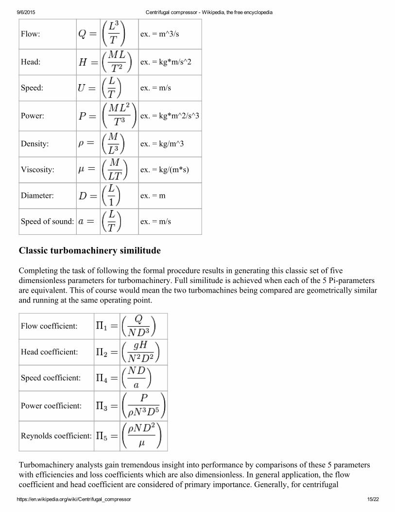
According to the theorem each of the eight main parameters are equated to its independent dimensions asfollows:
9/6/2015 Centrifugal compressor Wikipedia, the free encyclopedia
https://en.wikipedia.org/wiki/Centrifugal_compressor 15/22
Flow: ex. = m^3/s
Head: ex. = kg*m/s^2
Speed: ex. = m/s
Power: ex. = kg*m^2/s^3
Density: ex. = kg/m^3
Viscosity: ex. = kg/(m*s)
Diameter: ex. = m
Speed of sound: ex. = m/s
Classic turbomachinery similitude
Completing the task of following the formal procedure results in generating this classic set of fivedimensionless parameters for turbomachinery. Full similitude is achieved when each of the 5 Piparametersare equivalent. This of course would mean the two turbomachines being compared are geometrically similarand running at the same operating point.
Flow coefficient:
Head coefficient:
Speed coefficient:
Power coefficient:
Reynolds coefficient:
Turbomachinery analysts gain tremendous insight into performance by comparisons of these 5 parameterswith efficiencies and loss coefficients which are also dimensionless. In general application, the flowcoefficient and head coefficient are considered of primary importance. Generally, for centrifugal
9/6/2015 Centrifugal compressor Wikipedia, the free encyclopedia
https://en.wikipedia.org/wiki/Centrifugal_compressor 16/22
compressors, the velocity coefficient is of secondary importance while the Reynolds coefficient is oftertiary importance. In contrast, as expected for pumps, the Reynolds number becomes of secondaryimportance and the velocity coefficient almost irrelevant. It may be found interesting that the speedcoefficient may be chosen to define the yaxis of Figure 1.1, while at the same time the Reynoldscoefficient may be chosen to define the zaxis.
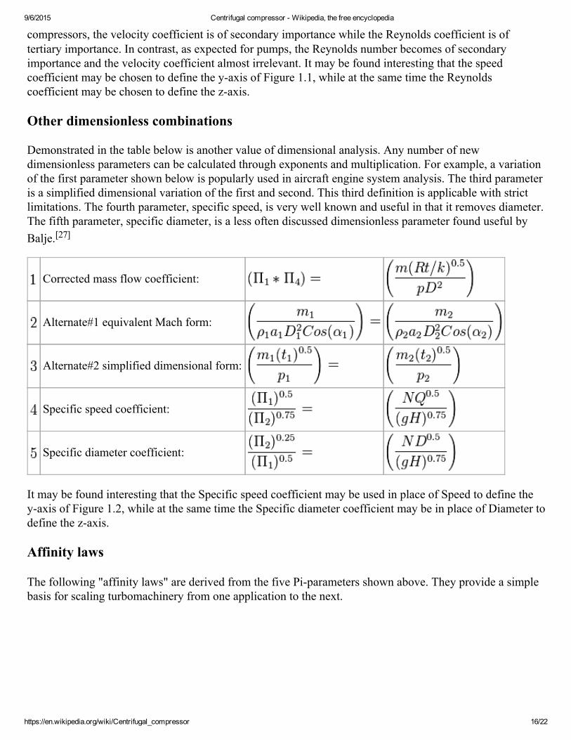
Other dimensionless combinations
Demonstrated in the table below is another value of dimensional analysis. Any number of newdimensionless parameters can be calculated through exponents and multiplication. For example, a variationof the first parameter shown below is popularly used in aircraft engine system analysis. The third parameteris a simplified dimensional variation of the first and second. This third definition is applicable with strictlimitations. The fourth parameter, specific speed, is very well known and useful in that it removes diameter.The fifth parameter, specific diameter, is a less often discussed dimensionless parameter found useful byBalje.[27]
Corrected mass flow coefficient:
Alternate#1 equivalent Mach form:
Alternate#2 simplified dimensional form:
Specific speed coefficient:
Specific diameter coefficient:
It may be found interesting that the Specific speed coefficient may be used in place of Speed to define theyaxis of Figure 1.2, while at the same time the Specific diameter coefficient may be in place of Diameter todefine the zaxis.
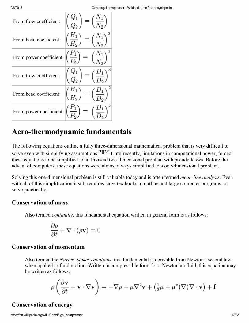
Affinity laws
The following "affinity laws" are derived from the five Piparameters shown above. They provide a simplebasis for scaling turbomachinery from one application to the next.
9/6/2015 Centrifugal compressor Wikipedia, the free encyclopedia
https://en.wikipedia.org/wiki/Centrifugal_compressor 17/22
From flow coefficient:
From head coefficient:
From power coefficient:
From flow coefficient:
From head coefficient:
From power coefficient:
Aerothermodynamic fundamentals
The following equations outline a fully threedimensional mathematical problem that is very difficult tosolve even with simplifying assumptions.[5][28] Until recently, limitations in computational power, forcedthese equations to be simplified to an Inviscid twodimensional problem with pseudo losses. Before theadvent of computers, these equations were almost always simplified to a onedimensional problem.
Solving this onedimensional problem is still valuable today and is often termed meanline analysis. Evenwith all of this simplification it still requires large textbooks to outline and large computer programs tosolve practically.
Conservation of mass
Also termed continuity, this fundamental equation written in general form is as follows:
Conservation of momentum
Also termed the Navier–Stokes equations, this fundamental is derivable from Newton's second lawwhen applied to fluid motion. Written in compressible form for a Newtonian fluid, this equation maybe written as follows:
Conservation of energy
9/6/2015 Centrifugal compressor Wikipedia, the free encyclopedia
https://en.wikipedia.org/wiki/Centrifugal_compressor 18/22
The First Law of Thermodynamics is the statement of the conservation of energy. Under specificconditions, the operation of a Centrifugal compressor is considered a reversible process. For areversible process, the total amount of heat added to a system can be expressed as where is temperature and is entropy. Therefore, for a reversible process:
Since U, S and V are thermodynamic functions of state, the above relation holds also for nonreversible changes. The above equation is known as the fundamental thermodynamic relation.
Equation of state
The classical ideal gas law may be written:
The ideal gas law may also be expressed as follows
where is the density, is the adiabatic index (ratio of specific heats), isthe internal energy per unit mass (the "specific internal energy"), is the specific heat at constantvolume, and is the specific heat at constant pressure.
With regard to the equation of state, it is important to remember that while air and nitrogen properties(near standard atmospheric conditions) are easily and accurately estimated by this simplerelationship, there are many centrifugal compressor applications where the ideal relationship isinadequate. For example, centrifugal compressors used for large air conditioning systems (waterchillers) use a refrigerant as a working gas that cannot be modeled as an ideal gas. Another exampleare centrifugal compressors design and built for the petroleum industry. Most of the hydrocarbongases such as methane and ethylene are best modeled as a real gas equation of state rather than idealgases. The Wikipedia entry for equations of state is very thorough.
Pros and cons
Pros
Centrifugal compressors are used throughout industry because they have fewer rubbing parts,are relatively energy efficient, and give higher airflow than a similarly sized reciprocatingcompressor or positivedisplacement compressor.
Cons
Their main drawback is that they cannot achieve the high compression ratio of reciprocatingcompressors without multiple stages. There are few onestage centrifugal compressors capableof pressure ratios over 10:1, due to stress considerations which severely limit the compressor'ssafety, durability and life expectancy.
Pros
9/6/2015 Centrifugal compressor Wikipedia, the free encyclopedia
https://en.wikipedia.org/wiki/Centrifugal_compressor 19/22
Centrifugal compressors are often used in small gas turbine engines like APUs (auxiliarypower units) and smaller aircraft gas turbines. A significant reason for this is that with currenttechnology, the equivalent flow axial compressor will be less efficient due primarily to acombination of rotor and variable stator tipclearance losses. Further, they offer the advantagesof simplicity of manufacturing and relatively low cost. This is due to requiring fewer stages toachieve the same pressure rise.
Cons
Centrifugal compressors are impractical, compared to axial compressors, for use in large gasturbine engines propelling large aircraft, due to the resulting weight and stress, and to thefrontal area presented by the diffuser.
Aerodynamic design methodology
Modern turbomachinery design is a compromise between fluid and thermodynamics, structural mechanicsand manufacturability.[6] Making the correct compromises requires appropriate experimental data anddesign experience. As precise as the fundamental equations above are, resultant design methods are manyand varied.[29]
Focusing on the thermofluid element, two logically opposed approaches are used to solve the fundamentalequations. The first is to analyze the existing performance of existing hardware: this analysis is a postexperiment activity used to explain what has happened. The second is to design new hardware: here designis a predictive activity similar to forecasting the weather.
Currently, popular turbomachinery design methods alternately solve two problems: first the designproblem, to define the air foil, and then the analysis problem, to detail the aerodynamic performance of thedesign. For "end users/customers" requiring the highest performance, designers incorporate numericaloptimization to direct these iterations, while sometimes pursuing a parallel experimental program.
In practice, design and analysis uses simplified 1D and 2D equation sets before performing the final 3Dsolutions. After this expansive aerodynamic problem is solved, an equally expansive set of design problemsremain involving the structural design and the manufacture of the centrifugal compressor. During the designstage, many considerations also need to be considered.[30]
Structural mechanics, manufacture and design compromise
Ideally, centrifugal compressor impellers have thin airfoil blades that are strong, each mounted on an lightrotor. This material would be easy to machine or cast and inexpensive. Additionally, it would generate nooperating noise, have an life while operating in any environment.
From the very start of the aerothermodynamic design process, the centrifugal impeller’s material andmanufacturing method must be accounted for within the design, whether it be plastic for a vacuum cleanerblower to aluminum alloy for a turbocharger, steel alloy for an air compressor or titanium alloy for a gasturbine. It is a combination of the centrifugal compressor impeller shape, its operating environment, itsmaterial and its manufacturing method that determines the impeller’s structural integrity.
See also
9/6/2015 Centrifugal compressor Wikipedia, the free encyclopedia
https://en.wikipedia.org/wiki/Centrifugal_compressor 20/22
Angular momentumCentrifugal forceCentripetal forceCoandă effectComputational Fluid DynamicsCompressibilityCoriolis effectCorrected speedDarcy–Weisbach equationGustaf de LavalEnthalpyEntropyEuler equations (fluid dynamics)Finite element analysisFluid dynamics
Gas lawsIdeal gas lawKinematicsReal gasRossby numberMach numberMultiphase flowNavierStokes equationsReynoldsaveraged Navier–StokesequationsReynolds transport theoremReynolds numberTurbulenceViscosityVon Karman Institute for Fluid Dynamics(VKI)
Threedimensional losses and correlation in turbomachineryEffects of mach number and shock losses in turbomachines
[29] [30]
References1. Shepard, Dennis G. (1956). Principles of Turbomachinery. McMillan. ISBN 0471855464. LCCN 56002849
(http://lccn.loc.gov/56002849).2. Aurel Stodola (1945). Steam and Gas Turbines. New York: P. Smith. OL 18625767M
(http://openlibrary.org/books/OL18625767M).3. Pfleiderer, C. (1952). Turbomachines. New York: SpringerVerlag.4. W. R. Hawthorne (1964). Aerodynamics Of Turbines and Compressors. Princeton New Jersey: Princeton
University Press. LCCN 585029 (http://lccn.loc.gov/585029).5. Lakshminarayana, B. (1996). Fluid Dynamics and Heat Transfer of Turbomachinery. New York: John Wiley &
Sons Inc. ISBN 0471855464.6. Japikse, David. Centrifugal Compressor Design and Performance. Concepts ETI . ISBN 0933283032.7. Japikse, David & Baines, Nicholas C. (1997). Introduction to Turbomachinery. Oxford: Oxford University press.
ISBN 0933283105.8. Japikse, David and Baines, N.C. (1998). Diffuser Design Technology. Concepts ETI . ISBN 0933283016.9. Japikse, David. Advanced Experimental Techniques in Turbomachinery. Concepts ETI. ISBN 0933283016.10. Peng, W. W. (2007). Fundamentals of Turbomachinery. New York: John Wiley & Sons Inc. ISBN 9780470
124222.11. Wislicenus, George Friedrich (1965). Fluid Mechanics of Turbomachinery in two volumes. New York: Dover.
ISBN 9780486613451.12. Wood, Bernard D. (1969). Applications of Thermodynamics. Reading, Massachusetts: Addison Wesley
Publishing Company. LCCN 7579598 (http://lccn.loc.gov/7579598).13. Streeter, Victor L. (1971). Fluid Mechanics fifth edition. New York: McGraw Hill Book Company. ISBN 007
0621918.14. Engeda, Abraham (1999). "From the Crystal Palace to the pump room"
(http://www.memagazine.org/backissues/membersonly/february99/features/crystal/crystal.html). MechanicalEngineering. ASME.
9/6/2015 Centrifugal compressor Wikipedia, the free encyclopedia
https://en.wikipedia.org/wiki/Centrifugal_compressor 21/22
15. Elliott Company. "Past, Present, Future, 19102010" (http://www.elliottturbo.com/Files/Admin/100th%20Anniversary/1930s%20%20O%20Line%20Blowers.pdf) (PDF). Elliott.Retrieved 1 May 2011.
16. API (July 2002). Std 6732002 Centrifugal Fans for Petroleum, Chemical and Gas Industry Services(http://global.ihs.com/doc_detail.cfm?item_s_key=00392744/). New York: API.
17. Whitfield, A. & Baines, N. C. (1990). Design of Radial Turbomachinery. Longman Scientific and Technical.ISBN 0470216670.
18. Aungier, Ronald H. (2000). Centrifugal Compressors, A Strategy for Aerodynamic Design and Analysis. ASMEPress. ISBN 0791800938.
19. Saravanamuttoo, H.I.H., Rogers, G.F.C. and Cohen, H. (2001). Gas Turbine Theory. PrenticeHall. ISBN 013015847X.
20. Baines, Nicholas C. (2005). Fundamentals of Turbocharging. Concepts ETI . ISBN 0933283148.21. "SAE Standards" (http://www.sae.org/standards/). SAE/standards/power and propulsion/engines. SAE
International. Retrieved 23 April 2011.22. API (July 2002). Std 6172002 Axial and Centrifugal Compressors and Expandercompressors for Petroleum,
Chemical and Gas Industry Services. New York: API.23. ASHRAE, American Society of Heating, Refrigeration and AirConditioning Engineers. "Standards &
Guidelines" (http://www.ashrae.org/technology/page/548). ASHRAE. Retrieved 23 April 2011.24. API (October 2007). Std 6722007 Packaged, Integrally Geared Centrifugal Air Compressors for Petroleum,
Chemical, and Gas Industry Services. New York: API.25. ASME PTC 101997 Test Code on Compressors and Exhausters (http://www.asme.org/kb/standards#des=PTC).
New York: ASME. 1997. ISBN 0791824500.26. Pampreen, Ronald C. (1993). Compressor Surge and Stall. Concepts ETI. ISBN 0933283059.27. Balje, O. E. (1961). Turbo Machines; a Guide to Design, Selection, and Theory. New York: John Wiley & Sons.
ISBN 0471060364.28. Cumpsty, N. A. (2004). Compressor Aerodynamics. Krieger Publishing. ISBN 1575242478.29. Xu, C. and R.S. Amano, The Development of a Centrifugal Compressor Impeller, International Journal for
Computational Methods in Engineering Science and Mechanics, Volume 10 Issue 4 2009, Pages 290 – 301.30. Xu, C., Design experience and considerations for centrifugal compressor development., J. of Aerospace Eng.
2007
External links
MIT Gas Turbine Laboratory (http://web.mit.edu/aeroastro/www/labs/GTL/gtl_about.html)(1948), First Marine Gas Turbine in Service. Journal of the American Society for Naval Engineers,60: 66–86. (http://onlinelibrary.wiley.com/doi/10.1111/j.15593584.1948.tb02754.x/abstract)doi:10.1111/j.15593584.1948.tb02754.x (https://dx.doi.org/10.1111%2Fj.15593584.1948.tb02754.x)A history of Chrysler turbine cars (http://www.aardvark.co.nz/pjet/chrysler.shtml)To find API codes, standards & publications (http://www.api.org/Publications/addenda/addref.cfm)[Broken Link]To find ASME codes, standards & publications (http://www.asme.org/)To find ASHRAE codes, standards & publications (http://www.ashrae.org/)Glenn Research Center at NASA (http://www.grc.nasa.gov/WWW/K12/airplane/centrf.html)Pontyak Resource Centre (http://pontyak.com/index.html)Hydrodynamics of Pumps, by Christopher Earls Brennen(http://authors.library.caltech.edu/25019/2/HydroPmp.pdf)
Retrieved from "https://en.wikipedia.org/w/index.php?title=Centrifugal_compressor&oldid=679135440"
Categories: Compressors
9/6/2015 Centrifugal compressor Wikipedia, the free encyclopedia
https://en.wikipedia.org/wiki/Centrifugal_compressor 22/22
This page was last modified on 2 September 2015, at 17:22.Text is available under the Creative Commons AttributionShareAlike License; additional terms mayapply. By using this site, you agree to the Terms of Use and Privacy Policy. Wikipedia® is aregistered trademark of the Wikimedia Foundation, Inc., a nonprofit organization.
![By David Torgesen. [1] Wikipedia contributors. "Pneumatic artificial muscles." Wikipedia, The Free Encyclopedia. Wikipedia, The Free Encyclopedia, 3 Feb.](https://static.fdocuments.in/doc/165x107/5519c0e055034660578b4b80/by-david-torgesen-1-wikipedia-contributors-pneumatic-artificial-muscles-wikipedia-the-free-encyclopedia-wikipedia-the-free-encyclopedia-3-feb.jpg)