Baltimore, Maryland Tyler Swartzwelder …...Baltimore, Maryland Tyler Swartzwelder Construction...
14
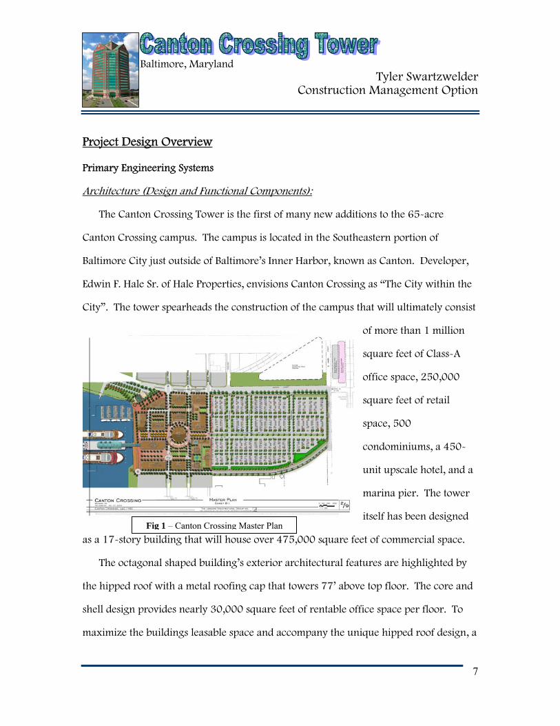
Baltimore, Maryland Tyler Swartzwelder Construction Management Option 7 Project Design Overview Primary Engineering Systems Architecture (Design and Functional Components): The Canton Crossing Tower is the first of many new additions to the 65-acre Canton Crossing campus. The campus is located in the Southeastern portion of Baltimore City just outside of Baltimore’s Inner Harbor, known as Canton. Developer, Edwin F. Hale Sr. of Hale Properties, envisions Canton Crossing as “The City within the City”. The tower spearheads the construction of the campus that will ultimately consist of more than 1 million square feet of Class-A office space, 250,000 square feet of retail space, 500 condominiums, a 450- unit upscale hotel, and a marina pier. The tower itself has been designed as a 17-story building that will house over 475,000 square feet of commercial space. The octagonal shaped building’s exterior architectural features are highlighted by the hipped roof with a metal roofing cap that towers 77’ above top floor. The core and shell design provides nearly 30,000 square feet of rentable office space per floor. To maximize the buildings leasable space and accompany the unique hipped roof design, a Fig 1 – Canton Crossing Master Plan
Transcript of Baltimore, Maryland Tyler Swartzwelder …...Baltimore, Maryland Tyler Swartzwelder Construction...
Baltimore, Maryland Tyler Swartzwelder
Construction Management Option
7
Project Design Overview
Primary Engineering Systems
Architecture (Design and Functional Components):
The Canton Crossing Tower is the first of many new additions to the 65-acre
Canton Crossing campus. The campus is located in the Southeastern portion of
Baltimore City just outside of Baltimore’s Inner Harbor, known as Canton. Developer,
Edwin F. Hale Sr. of Hale Properties, envisions Canton Crossing as “The City within the
City”. The tower spearheads the construction of the campus that will ultimately consist
of more than 1 million
square feet of Class-A
office space, 250,000
square feet of retail
space, 500
condominiums, a 450-
unit upscale hotel, and a
marina pier. The tower
itself has been designed
as a 17-story building that will house over 475,000 square feet of commercial space.
The octagonal shaped building’s exterior architectural features are highlighted by
the hipped roof with a metal roofing cap that towers 77’ above top floor. The core and
shell design provides nearly 30,000 square feet of rentable office space per floor. To
maximize the buildings leasable space and accompany the unique hipped roof design, a
Fig 1 – Canton Crossing Master Plan

Baltimore, Maryland Tyler Swartzwelder
Construction Management Option
8
2-story Utility Distribution Center (UDC) was built across the street from the tower.
The UDC houses the main mechanical and electrical systems that power the building.
With its unique location, the tower provides breathtaking views of Baltimore’s Inner
Harbor, as well the city’s entire skyline. Even as Canton Crossing continues to grow,
the Canton Crossing Tower will remain the tallest building throughout the campus.
Since it is easily visible from busy locations such as the Inner Harbor, Fort McHenry,
and Interstate 95 & 895, the Canton Crossing Tower is sure to put Canton on the map.
Building Envelope:
The building envelope of the tower is quite unique. The tower has an octagonal
shaped shell. The four largest sides of the building are comprised of precast concrete
panels with thin face brick and 6” deep aluminum window wall systems. The top of
these four sides are completed with a triangular peak which is home to the 1st Mariner
Bank name and symbol in gold. Two of the smaller
sides are the grand entrances, located on either side of
the building. These walls are designed with a 7 ½”
deep aluminum curtain wall system. The final two
sides of the tower are designed the same as the four
large ones with the 6” deep aluminum window wall
systems. The four smaller sides are all capped off with
balconies on the 17th floor.
The roof of the Canton Crossing Tower is what makes this high-rise building
distinctive. The hipped roof design towers 77’ above the top floor. Each of the four
Fig 2 – Building Rendering

Baltimore, Maryland Tyler Swartzwelder
Construction Management Option
9
Fig 3 – Existing Site Aerial View
Fig 4 – Steel & Precast Erection with a view of fireproofing plastic
hips is covered by a standing seam metal roof. In between the four hips, the core is
covered by insulated aluminum panels that then meet the standing seam metal roof cap.
The peak of the 17-story building is complimented by a flag pole.
Construction:
The site for Canton Crossing Tower
caused dilemmas for the construction team
from day one. The site, the former location
of an Exxon terminal, was bid as a clean
site but was far from it. The soil on the site was
classified as contaminated soil and required a Corrective Action Plan (CAP) for the
remediation of light non-aqueous phase liquids (LNAPL). The plan included the
excavation and transportation of the
contaminated soils to an offsite location.
Also, before anyone was permitted to
work in the contaminated soils they
must first complete a 40 hour
Hazardous Awareness Training.
Once the project broke ground the
concrete piles began to be placed. The
steel structure was erected at a very
rapid pace. The construction manager followed a demanding schedule of one floor per
week. The one floor per week included all of the following; structural steel placed,
Baltimore, Maryland Tyler Swartzwelder
Construction Management Option
10
metal decking placed, and the suspended concrete slab poured. Also, as a safety
measure, 75% of the above floor metal decking had to be placed before work began on
the floor below. At times the schedule seemed in jeopardy, but by the aggressive
management of many individuals the schedule was able to be attained.
The site logistics were in the favor of the construction team for this project. The
large site footprint made steel staging a manageable task. Other positive site features
were the two surrounding public roadways running on either side of the tower. These,
along with the immediate access to Interstate 95, gave some leeway to the delivery
methods. Two tower cranes were used for the steel erection and the concrete slabs
were placed by pump. The construction team also had two material hoists that ran the
length of the 17-story tower during construction. These hoists were crucial to the
project because with no elevators, production would have been seriously affected.
As the contract with the owner was for simply the core and shell of the building, the
tenant fit-out brought the most challenging aspect of managing the project. Gilbane,
the base building CM, was not awarded any of the tenant’s CM contracts. Therefore
while Gilbane was attempting to complete the base building, tenant hired CM’s were
beginning their work on the rented floors. Intense coordination and good cooperation
had to be implemented for the parties to work side by side.
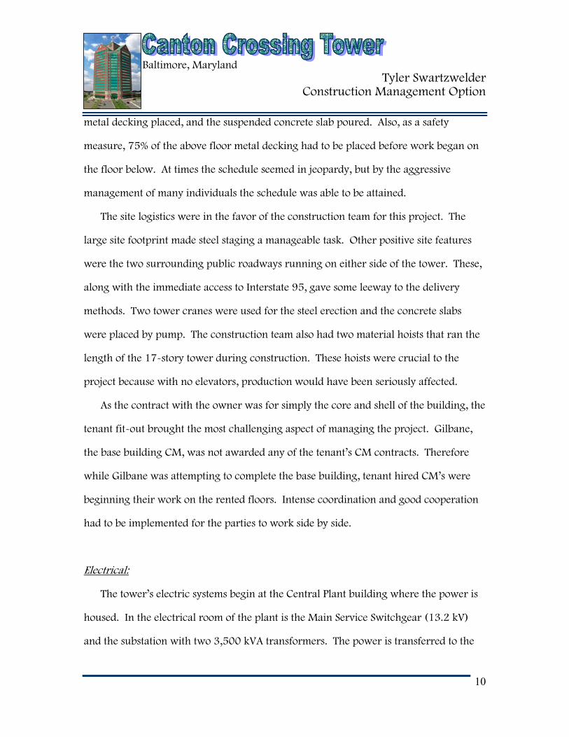
Electrical:
The tower’s electric systems begin at the Central Plant building where the power is
housed. In the electrical room of the plant is the Main Service Switchgear (13.2 kV)
and the substation with two 3,500 kVA transformers. The power is transferred to the
Baltimore, Maryland Tyler Swartzwelder
Construction Management Option
11
Fig 5 – Typical Floor Electrical Rm showing bust ducts and a transformer
power through 2 – 9-way ductbanks, one for normal power and one for emergency
power. The 15 kV switchgear located in the Ground Floor Electrical Room of the tower
is where the 13.8 kV normal open loop feeders enter from the Central Plant Ductbanks.
The power runs vertically through the entire building through 7 main busways, with
one more optional plug-in busway.
The busways run through electrical
rooms that are located on each side
of the tower’s core. The one room
houses a lighting busway (600A,
480/277V, 3θ, 4W), computer
busway (1600A, 480V, 3θ, 3W),
emergency life safety busway
(600A, 480/277V, 3θ, 4W), and an
emergency standby busway (600A, 480/277V, 3θ, 4W). The opposite electrical room
houses the HVAC busway (2000A, 480/277V, 3θ, 4W), computer busway (1600A,
480V, 3θ, 3W), lighting busway (1600A, 480/277V, 3θ, 4W), and the optional
standby busway (800A, 480V, 3θ, 4W). Each electrical room is also equipped with 3
transformers and six electrical panels. On the 18th floor, the electrical systems floor,
the busways come to six ATS’s, two main substations, and an emergency substation.
Baltimore, Maryland Tyler Swartzwelder
Construction Management Option
12
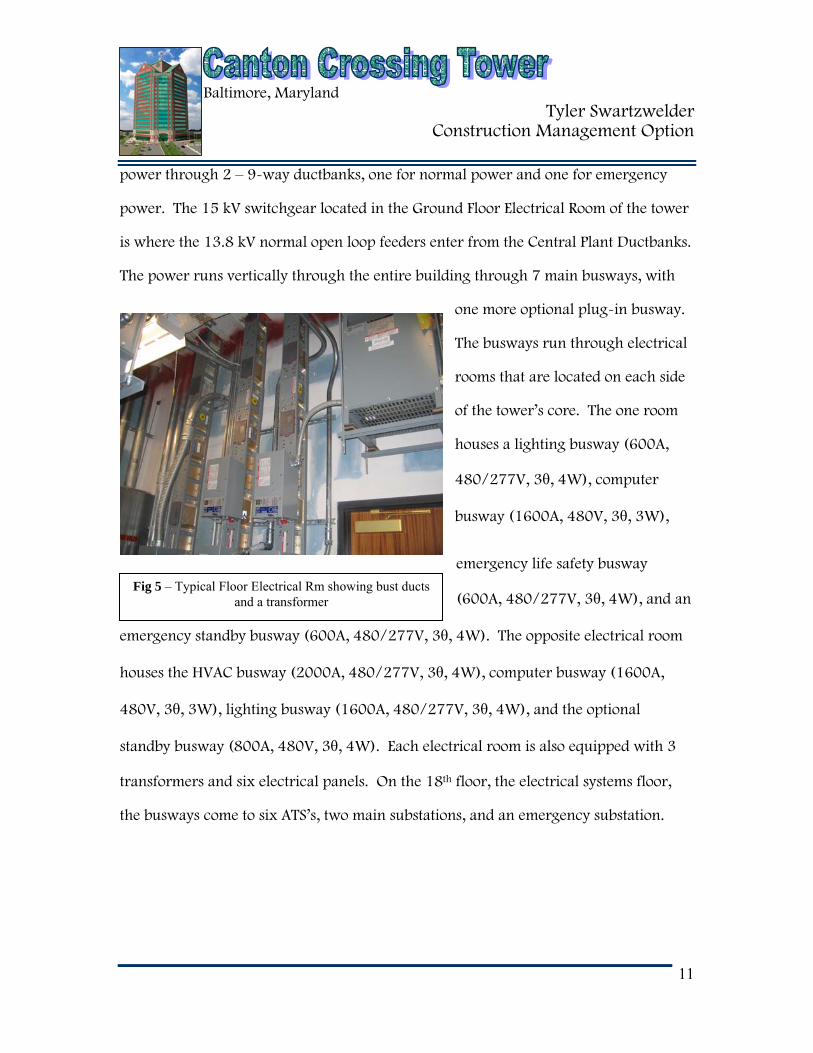
Fig 6 – Architectural Lighting in main lobby
Lighting:
The tower’s interior lighting fixture schedule is mostly comprised of 277 V recess
mounted fluorescent lamps. The lighting of the building is served via 480/277, 3-
phase, 4 wire panels. On the ground floor, the lighting was designed with more of an
architectural purpose. This floor’s lighting ranges from polished brass wall mounted
fixtures to ceiling recessed compact
fluorescent downlights. The typical
floors contain 2’x2’ parabolic
fluorescent fixtures in the core areas
and 4’ heavy duty industrial
fluorescents in the tenant shell
areas. On the exterior hardscape of
the tower, pole mounted light fixtures, in-grade up lights, and bollard lights combine to
beautify the surrounding area.
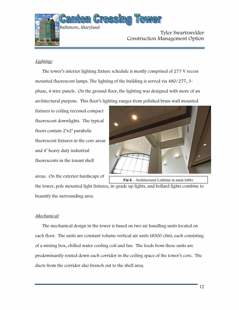
Mechanical:
The mechanical design in the tower is based on two air handling units located on
each floor. The units are constant volume vertical air units (8500 cfm), each consisting
of a mixing box, chilled water cooling coil and fan. The feeds from these units are
predominantly routed down each corridor in the ceiling space of the tower’s core. The
ducts from the corridor also branch out to the shell area.
Baltimore, Maryland Tyler Swartzwelder
Construction Management Option
13
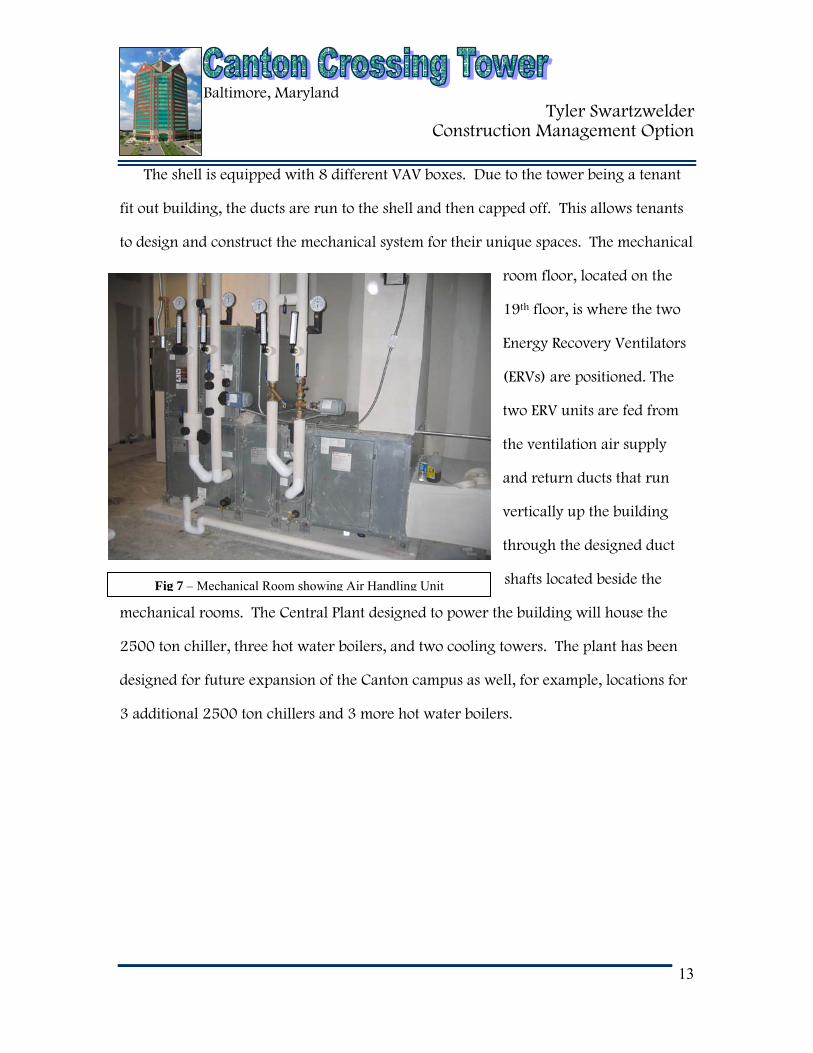
Fig 7 – Mechanical Room showing Air Handling Unit
The shell is equipped with 8 different VAV boxes. Due to the tower being a tenant
fit out building, the ducts are run to the shell and then capped off. This allows tenants
to design and construct the mechanical system for their unique spaces. The mechanical
room floor, located on the
19th floor, is where the two
Energy Recovery Ventilators
(ERVs) are positioned. The
two ERV units are fed from
the ventilation air supply
and return ducts that run
vertically up the building
through the designed duct
shafts located beside the
mechanical rooms. The Central Plant designed to power the building will house the
2500 ton chiller, three hot water boilers, and two cooling towers. The plant has been
designed for future expansion of the Canton campus as well, for example, locations for
3 additional 2500 ton chillers and 3 more hot water boilers.
Baltimore, Maryland Tyler Swartzwelder
Construction Management Option
14
Fig 8 – Aerial view showing poured pile caps and beginning of column erection
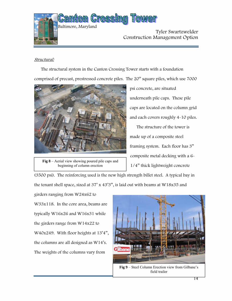
Fig 9 – Steel Column Erection view from Gilbane’s field trailer
Structural:
The structural system in the Canton Crossing Tower starts with a foundation
comprised of precast, prestressed concrete piles. The 20” square piles, which use 7000
psi concrete, are situated
underneath pile caps. These pile
caps are located on the column grid
and each covers roughly 4-10 piles.
The structure of the tower is
made up of a composite steel
framing system. Each floor has 3”
composite metal decking with a 6-
1/4” thick lightweight concrete
(3500 psi). The reinforcing used is the new high strength billet steel. A typical bay in
the tenant shell space, sized at 37’ x 43’3”, is laid out with beams at W18x35 and
girders ranging from W24x62 to
W33x118. In the core area, beams are
typically W16x26 and W16x31 while
the girders range from W14x22 to
W40x249. With floor heights at 13’4”,
the columns are all designed as W14’s.
The weights of the columns vary from

Baltimore, Maryland Tyler Swartzwelder
Construction Management Option
15
Fig 10 – Tower cranes from afar
Fig 11 – Tower crane connection to building
82 lb/ft to 605 lb/ft. The columns ultimately rest on top of the pile caps at the
foundation level.
The primary lateral system in the building are braced frames, both concentrically
braced and eccentrically braced. Moment frames are also used as a lateral system
around the perimeter of the building. The lower level of the hipped roof system has a
typical beam size of W16x26 and a typical girder size of W24x76. The upper level of
the roof use W12x26 beams and W33x118 girders.
The steel of the building was placed using two tower cranes positioned on the North
and South ends of the towers exterior perimeter. The height of the tower cranes were
340 ft & 380 ft respectively. They have a concrete foundation with eight precast piles
under each. The pieces of the cranes, known as “towers”, were each approximately 20’
tall. To remain structurally safe, the maximum free standing towers are nine or 180’.
Once the cranes were above the 180’ height limit, they had to be tied into the building
structure.
Baltimore, Maryland Tyler Swartzwelder
Construction Management Option
16
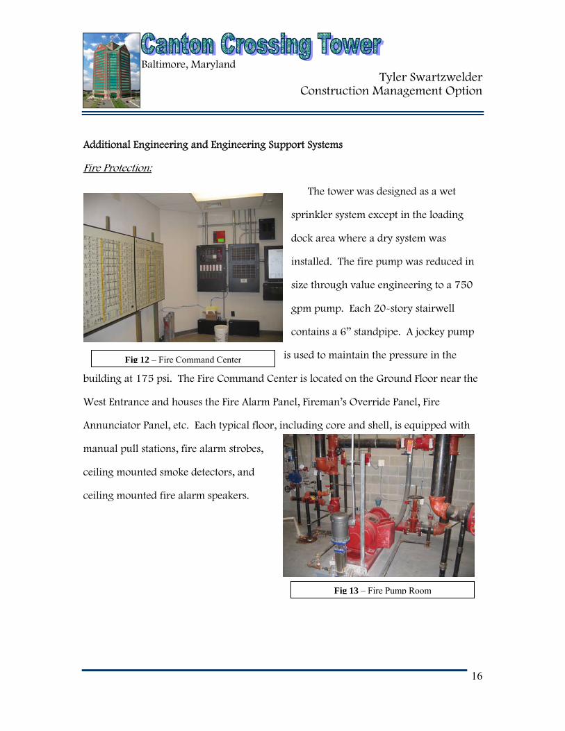
Fig 12 – Fire Command Center
Fig 13 – Fire Pump Room
Additional Engineering and Engineering Support Systems
Fire Protection:
The tower was designed as a wet
sprinkler system except in the loading
dock area where a dry system was
installed. The fire pump was reduced in
size through value engineering to a 750
gpm pump. Each 20-story stairwell
contains a 6” standpipe. A jockey pump
is used to maintain the pressure in the
building at 175 psi. The Fire Command Center is located on the Ground Floor near the
West Entrance and houses the Fire Alarm Panel, Fireman’s Override Panel, Fire
Annunciator Panel, etc. Each typical floor, including core and shell, is equipped with
manual pull stations, fire alarm strobes,
ceiling mounted smoke detectors, and
ceiling mounted fire alarm speakers.

Baltimore, Maryland Tyler Swartzwelder
Construction Management Option
17
Fig 14 – Elevator Machine Room
Transportation:
The building consists of 8 traction elevators, four on each side of the lobby. One of
the eight elevators will be used as a service elevator with a capacity of 4,500 lbs and
speed of 700 f.p.m. The service elevator will stop on all floors up to the 19th floor. The
other 7 elevators are strictly passenger elevators with a capacity of 3,500 lbs and a
speed of 700 f.p.m. These elevators will stop on all floors up to the 17th floor. The
elevator pits are approximately 8’4” deep with a sump pump in each pit. The 20th floor
of the tower houses the elevator
machine room.
Telecommunications:
Due to the 17-story office tower being designed as a tenant fit-out, the
telecommunications aspect of the base building is somewhat minute. The Main
Telecommunications Room on the ground floor is where the 12-way incoming
ductbank enters from the Central Plant. Each of the typical floors is equipped with two
Tele/Data Rooms. Under base building contract, these rooms are built so that each
tenant may come in and fit-out their own telecommunications system.

Baltimore, Maryland Tyler Swartzwelder
Construction Management Option
18
Fig 15 – Concrete Pump during foundation pours
The security system of the building is important because the main tenant of the
tower is 1st Mariner Bank. The owner opted to hold the contract with the security
subcontractor as opposed to Gilbane holding that contract. The tower is inaccessible to
the public after hours, with a 24-hour security crew on board. The exterior entrances
are equipped with a telecom system for entry during non-working hours. Each interior
floor has been set up with four security cameras that monitor the entire core area.
Demolition Required
No demolition was required for the Canton Crossing Tower.
Cast in Place Concrete
The cast in place concrete for the composite floor slabs is lightweight with a
minimum compressive strength of 3500 psi. The 3” metal decking will act as the
horizontal formwork for the concrete, while the steel toe plate around the perimeter
will act as the vertical formwork. The
concrete is to be poured in strips
perpendicular to the steel girders. The cast
in place concrete is placed by the pump
method.

Baltimore, Maryland Tyler Swartzwelder
Construction Management Option
19
Fig 16 – Precast connections to steel columns
Precast Concrete
The architectural precast panels that were designed for the tower were constructed
by The Shockey Precast Group at their plant in Winchester, Virginia. The panels were
then transferred by tractor and trailer to the construction site as needed for erection.
The two tower cranes were used for the erection of the precast panels.
Precast connections were detailed by Shockey. The connections were a combination
of L-shaped steel angles for lateral support, with bearing connection plates embedded
in the concrete. The angles were
attached to the structure columns and
welded to embedded plates in the
precast.
Masonry
The masonry used in the tower was very minimal. At locations where masonry was
used, it was non-load bearing.

Baltimore, Maryland Tyler Swartzwelder
Construction Management Option
20
Fig 17 – Shoring for elevator pits
Support of Excavation
The building required a minimal amount of excavation, therefore the only
excavation support system needed was around the elevator pits where sheeting and
shoring was used. There was no
dewatering system used on the
project due to the minor excavation.