AT91 USB Integrated Circuit(s) Cards Interface...
18
AT91 USB Integrated Circuit(s) Cards Interface Devices (CCID) Driver Implementation 1. Introduction The Integrated Circuit(s) Cards Interface Devices (CCID) class extends the USB specification in order to provide a standard means of handling Integrated Circuit(s) Card (ICC) devices such as Smart Cards conforming to ISO/IEC 7816 specifications. This application note describes how to implement a CCID driver with the AT91 USB Framework provided by Atmel ® for use with its AT91 ARM ® Thumb ® based microcontrollers. • First, generic information about CCID-specific definitions and requirements is given. • This document then details how to use the CCID class to communicate with a Smart Card. 2. Related Documents 1. CCID Device Class: Smart Card, specification for Integrated Circuit(s) Cards Interface Devices, revision 1.1, April 22, 2005. 2. Identification cards, Integrated circuits cards, part 3: Cards with contacts: electrical interface and transmission protocols, Version 2.1c2, 2005-06-3. ISO/IEC FDIS 7816-3: 2005(E) 3. Identification cards, Integrated circuits cards, part 4: Organization, security and commands for interchange, 2004-10-14. ISO/IEC FDIS 7816-4: 2004(E) 4. Atmel Corp., AT91 USB Framework, 2006, lit ° 6263 5. USB specification 2.0: http://www.usb.org 6. Software ISO 7816 I/O Line Implementation, Atmel Application Note, lit° 1154 7. DWG Smart-Card Integrated Circuit(s) Card Interface Devices http://www.usb.org AT91 ARM Thumb Microcontrollers Application Note 6348A–ATARM–06-Jul-09
Transcript of AT91 USB Integrated Circuit(s) Cards Interface...

AT91 ARM Thumb Microcontrollers
Application Note
6348A–ATARM–06-Jul-09
AT91 USB Integrated Circuit(s) Cards Interface Devices (CCID) Driver Implementation
1. IntroductionThe Integrated Circuit(s) Cards Interface Devices (CCID) class extends the USBspecification in order to provide a standard means of handling Integrated Circuit(s)Card (ICC) devices such as Smart Cards conforming to ISO/IEC 7816 specifications.
This application note describes how to implement a CCID driver with the AT91 USBFramework provided by Atmel® for use with its AT91 ARM® Thumb® basedmicrocontrollers.
• First, generic information about CCID-specific definitions and requirements is given.
• This document then details how to use the CCID class to communicate with a Smart Card.
2. Related Documents1. CCID Device Class: Smart Card, specification for Integrated Circuit(s) Cards
Interface Devices, revision 1.1, April 22, 2005.2. Identification cards, Integrated circuits cards, part 3: Cards with contacts:
electrical interface and transmission protocols, Version 2.1c2, 2005-06-3. ISO/IEC FDIS 7816-3: 2005(E)
3. Identification cards, Integrated circuits cards, part 4: Organization, security and commands for interchange, 2004-10-14. ISO/IEC FDIS 7816-4: 2004(E)
4. Atmel Corp., AT91 USB Framework, 2006, lit ° 6263 5. USB specification 2.0: http://www.usb.org6. Software ISO 7816 I/O Line Implementation, Atmel Application Note, lit°
11547. DWG Smart-Card Integrated Circuit(s) Card Interface Devices
http://www.usb.org

3. Abbreviations and Terms
4. CCID Device ClassThis section gives generic details on the CCID class, including its purpose, architecture and howit is supported by various operating systems.
4.1 PurposeThe CCID class has been specifically designed for Smart Card Devices.
4.2 Architecture
4.2.1 InterfacesA CCID device only needs one interface descriptor. It should have the CCID interface class codein its bInterfaceClass field. There are special subclass and protocol codes to specify.
4.2.2 EndpointsThe CCID requires three endpoints.
One endpoint BULK IN and one endpoint BULK OUT. They are mandatory and should alwaysbe declared.
APDU Application Protocol Data Unit
ATR Answer to Reset
CCID Integrated Circuit(s) Cards Interface Devices
Cold RESET The sequence starts with the ICC powered off.
ICC Integrated Circuit(s) Card (Used interchangeably with Smart Card)
ICCD Integrated Circuit(s) Card Devices conforming to this specification.Used interchangeably with USB-ICC.
Interface Device Terminal communication device or machine to which the ICC is electrically connected during operation [ISO/IEC 7816-3].
Lc Optional part of the body of a command APDU. Its size is 0, 1 or 3 bytes. The maximum number of bytes present in this body.
LeOptional part of the body of a command APDU. Its size is 0, 1, 2, or 3 bytes. The maximum number of bytes expected in the data field of the response APDU.
P1, P2 INS parameter of a command header.
P3 INS parameter of a command header. P3 contains Lc or Le
RFU Reserved for Future Use
TPDU Transport Protocol Data Unit
USB-ICC USB Integrated Circuit(s) Card. An ICC providing a USB interface [ISO/IEC 7816-12]. Used interchangeably with ICCD.
Warm RESET The sequence starts with the ICC already powered
26348A–ATARM–06-Jul-09
Application Note

Application Note
The interrupt pipe is mandatory for a CCID that supports ICC insertion/removal. It is optional fora CCID with ICCs that are always inserted and are not removable.
Endpoint 0 is used for class-specific requests. In addition, the host can also explicitly request orsend report data through this endpoint.
The Bulk IN and OUT endpoints are used for sending data to the host, and to receiveinformation.
The Interrupt endpoint is used for Insertion and Removal of the card, and in case of hardwareerror.
Figure 4-1. CCID Class Driver Architecture
4.2.3 Class-Specific DescriptorsThe smart card device descriptor specifies certain device features or capabilities. Please refer tothe CCID specifications for more information.
4.2.3.1 CCID DescriptorThe CCID descriptor gives information about the CCID specification revision used, the countryfor which a device is localized, and lists the number of class-specific descriptors, including theirlength and type. The format is described in Table 4-1.
HOST
Control 0 Bulk IN Bulk OUT Interrupt IN
Configuration ISO 7816
Smart Card
TP
DU
DEVICE
Table 4-1. CCID Descriptor Format
Field Size (bytes) Description
bLength 1 Total length of the CCID descriptor
bDescriptorType 1 CCID descriptor type (21h)
bcdCCID 2 CCID specification release number in Binary Coded Decimal (BCD) format.
bMaxSlotIndex 1 Index of the highest available slot.
bVoltageSupport 1 What voltages the CCID can supply to its slots
dwProtocols 4 Supported protocol types
36348A–ATARM–06-Jul-09

4.2.4 Class-specific Requests
4.2.4.1 GetDescriptorWhile GET_DESCRIPTOR is a standard request (defined in the USB specification 2.0), newdescriptor type values have been added for the CCID class. They make it possible for the host torequest the CCID descriptor, ABORT descriptor, GET_CLOCK_FREQUENCY descriptor andGET_DATA_RATES descriptor used by the device.
When requesting a CCID-specific descriptor, the wIndex field of the request must be set to theCCID interface number. For standard requests, this field is either set to 0 or, for String descrip-tors, to the index of the language ID used.
4.3 Host DriversMicrosoft® class CCID driver is used to drive the CCID without any vendor-specific software.usbccid.sys can be found on the installation disk provided by Windows®, or can be downloadedfrom the Windows Update web site during the new device installation procedure.
Specific software is used to send the APDU command to the Smart Card.
5. CCID ImplementationThis section describes how to implement a Smart Card device using the CCID class and theAT91 USB framework. For more information about the framework, please refer to the AT91 USBFramework application note; details about the USB and the CCID class can be found in the USBspecification 2.0 and the CCID specification documents, respectively.
5.1 ArchitectureThe AT91 USB Framework offered by Atmel makes it easy to create USB class drivers. Theexample software described in the current chapter is based on this framework. Figure 5-1 showsthe application architecture.
dwDefaultClock 4 Default ICC clock frequency in KHz
dwMaximumClock 4 Maximum supported ICC clock frequency in KHz
bNumClockSupported 4 Number of clock frequencies that are supported by the CCID
...
Table 4-1. CCID Descriptor Format
Field Size (bytes) Description
46348A–ATARM–06-Jul-09
Application Note

Application Note
Figure 5-1. Application Architecture Using the AT91 USB Framework
5.2 Descriptors
5.2.1 Device DescriptorThe device descriptor of a CCID device is very basic, since the CCID class code is only specifiedat the Interface level. Thus, it only contains standard values, as shown below:
static const USBDeviceDescriptor deviceDescriptor = {
sizeof(USBDeviceDescriptor),
USBGenericDescriptor_DEVICE,
USBDeviceDescriptor_USB2_00,
0,
0,
0,
BOARD_USB_ENDPOINTS_MAXPACKETSIZE(0),
CCIDDriverDescriptors_VENDORID,
CCIDDriverDescriptors_PRODUCTID,
CCIDDriverDescriptors_RELEASE,
1, // Index of manufacturer description
2, // Index of product description
3, // Index of serial number description
1 // One possible configuration
};
Note that the Vendor ID is a special value attributed by the USB-IF organization. The product IDcan be chosen freely by the vendor.
5.2.2 Configuration DescriptorSince one interface is required by the CCID specification, this must be specified in the configura-tion descriptor. There is no other value of interest to put here.
56348A–ATARM–06-Jul-09

{
sizeof(USBConfigurationDescriptor),
USBGenericDescriptor_CONFIGURATION,
sizeof(CCIDDriverConfigurationDescriptors),
1, // One interface in this configuration
1, // This is configuration #1
0, // No associated string descriptor
BOARD_USB_BMATTRIBUTES,
USBConfigurationDescriptor_POWER(100)
},
When the Configuration descriptor is requested by the host (by using the GET_DESCRIPTORcommand), the device must also send all the related descriptors, i.e. Interface, endpoint andclass-specific descriptors. It is convenient to create a single structure to hold all this data, forsending everything in one chunk. In the example software, a CCIDDriverConfigurationDescrip-tors structure has been declared for that purpose.
5.2.3 CCID Class Interface DescriptorThe interface descriptor is for the CCID Class Interface. It should specify the Smart Card Classcode (0Bh).
A CCID device needs to send and receive data from the host. This means the CCID needs bulkIN, bulk OUT and Interrupt IN endpoints. So the bNumEndpoints field will have to be set to 3.This interface also uses the default Control endpoint, but this is not taken into account here.
Here is the whole Interface descriptor:
{
sizeof(USBInterfaceDescriptor),
USBGenericDescriptor_INTERFACE,
0, // Interface 0
0, // No alternate settings
3, // uses bulk-IN, bulk-OUT and interrupt-IN
SMART_CARD_DEVICE_CLASS,
0, // Subclass code
0, // bulk transfers optional interrupt-IN
0 // No associated string descriptor
},
5.2.4 CCID DescriptorAn Interface descriptor is followed by the CCID descriptor. The CCID descriptor gives informa-tion about the number and types of the other defined descriptors.
Example software for the Smart Card.
{
sizeof(CCIDDescriptor), // bLength: Size of this descriptor in bytes
CCID_DECRIPTOR_TYPE, // bDescriptorType:Functional descriptor type
66348A–ATARM–06-Jul-09
Application Note

Application Note
CCID1_10, // bcdCCID: CCID version
0, // bMaxSlotIndex: Value 0 indicates that one slot is supported
VOLTS_5_0, // bVoltageSupport
PROTOCOL_TO, // dwProtocols
3580, // dwDefaultClock
3580, // dwMaxClock
0, // bNumClockSupported
9600, // dwDataRate : 9600 bauds
9600, // dwMaxDataRate : 9600 bauds
0, // bNumDataRatesSupported
0xfe, // dwMaxIFSD
0, // dwSynchProtocols
0, // dwMechanical
//0x00010042, // dwFeatures: Short APDU level exchanges
CCID_FEATURES_AUTO_PCONF | CCID_FEATURES_AUTO_PNEGO | CCID_FEATURES_EXC_TPDU,
0x0000010F, // dwMaxCCIDMessageLength: For extended APDU level the value shall be between 261 + 10
0xFF, // bClassGetResponse: Echoes the class of the APDU
0xFF, // bClassEnvelope: Echoes the class of the APDU
0, // wLcdLayout: no LCD
0, // bPINSupport: No PIN
1 // bMaxCCIDBusySlot
},
5.2.5 Physical DescriptorA physical descriptor is useless for a CCID device, so there will not be any defined in thisexample.
5.2.6 Endpoint DescriptorSince it has been specified that the CCID interface uses 3 endpoints, corresponding endpointdescriptors must now be defined. As mentioned previously, there are bulk OUT, bulk IN andInterrupt IN endpoints.
Addresses 00h and 03h are already taken by the default Control endpoint 0 and the Interrupt INnotification endpoint (respectively), the bulk OUT and bulk IN endpoints will take addresses 01hand 02h.
Additionally, an Interrupt endpoint maximum packet size should be as small as possible. Thehost must reserve a minimum amount of bandwidth which depends on this value. Defining asmall value minimizes the loss of bandwidth, but is only possible when the data size is known. Inthis case, it will always be 3 bytes, so wMaxPacketSize can be set accordingly.
Finally, since a CCID device response latency is not extremely critical, it can be safely set to ahigh value. In this example, the endpoint is polled every 16 ms.
// Bulk-OUT endpoint descriptor
{
sizeof(USBEndpointDescriptor),
76348A–ATARM–06-Jul-09

USBGenericDescriptor_ENDPOINT,
USBEndpointDescriptor_ADDRESS( USBEndpointDescriptor_OUT, CCID_EPT_DATA_OUT ),
USBEndpointDescriptor_BULK,
MIN(BOARD_USB_ENDPOINTS_MAXPACKETSIZE(CCID_EPT_DATA_OUT),
USBEndpointDescriptor_MAXBULKSIZE_FS),
0x00 // Does not apply to Bulk endpoints
},
// Bulk-IN endpoint descriptor
{
sizeof(USBEndpointDescriptor),
USBGenericDescriptor_ENDPOINT,
USBEndpointDescriptor_ADDRESS( USBEndpointDescriptor_IN, CCID_EPT_DATA_IN ),
USBEndpointDescriptor_BULK,
MIN(BOARD_USB_ENDPOINTS_MAXPACKETSIZE(CCID_EPT_DATA_IN),
USBEndpointDescriptor_MAXBULKSIZE_FS),
0x00 // Does not apply to Bulk endpoints
},
// Notification endpoint descriptor
{
sizeof(USBEndpointDescriptor),
USBGenericDescriptor_ENDPOINT,
USBEndpointDescriptor_ADDRESS( USBEndpointDescriptor_IN, CCID_EPT_NOTIFICATION ),
USBEndpointDescriptor_INTERRUPT,
MIN(BOARD_USB_ENDPOINTS_MAXPACKETSIZE(CCID_EPT_NOTIFICATION),
USBEndpointDescriptor_MAXINTERRUPTSIZE_FS),
0x10
}
5.2.7 String DescriptorsSeveral descriptors can be commented with a string descriptor. The latter is completely optionaland does not influence the detection of the device by the operating system. Whether or not toinclude them is entirely up to the programmer.
5.3 Class-Specific RequestsA number of CCID-only requests are defined in the corresponding specification. They havealready been described in Section 4.2.4 on page 4. This section details their implementationregarding the current example of a CCID device.
A driver request handler should first differentiate between class-specific and standard requestsusing the corresponding bits in the bmRequestType field. In most cases, standard requests canbe immediately forwarded to the standard request handler method; class-specific methods mustbe decoded and treated by the custom handler.
86348A–ATARM–06-Jul-09
Application Note
Application Note
5.3.1 Get DescriptorThree values have been added by the CCID specification for the GET_DESCRIPTOR request.The high byte of the wValue field contains the type of the requested descriptor; in addition to thestandard types, the CCID specification adds the ABORT (01h), GET_CLOCK_FREQUENCY(02h) and GET_DATA_RATES (03h) types.
A slight complexity of the GET_DESCRIPTOR and SET_DESCRIPTOR requests is that thoseare standard requests, but the standard request handler (USBDDriver_RequestHandler) mustnot always be called to treat them (since they may refer to CCID descriptors). The solution is tofirst identify GET/SET_DESCRIPTOR requests, treat the CCID-specific cases and, finally, for-ward any other request to the standard handler.
In this case, a GET_DESCRIPTOR request for the physical descriptor is first forwarded to thestandard handler, and STALLed there because it is not recognized. This is done because thedevice does not have any physical descriptors, and thus, does not need to handle the associ-ated request.
5.3.2 Set DescriptorThis request is optional and is never issued by most hosts. It is not implemented in this example.
5.4 ISO7816The ISO7816 software provided in this example is used to transform APDU commands to TPDUcommands for the smart card.
The ISO7816 implemented is for the protocol T = 0 only.
The send and the receive of a character is made under polling.
In the ISO7816_Init file 3 pins of the card are defined. The user must change these pins accord-ing to the specific environment.
See paragraph “ISO7816 Mode Overview” in the corresponding Atmel product datasheet.
3 or 4 PIO pins are used, see Section 6.1 for the Pin connections:
PIN_ISO7816_RSTMC: for 7816_RST
PINS_ISO7816: which defines USART pin, CLOCK pin and the RSTMC pin
PIN_SMARTCARD_CONNECT: Smartcard detection pin (if present)
The driver is compliant with cases 1, 2, 3 of the ISO7816-4 specification.
5.4.1 USART ConfigurationFirst, configure the USART in mode 7816, mode T=0, 1 stop bit, 8 chars, parity even.
Refer to the corresponding Atmel product datasheet, paragraph “Baud Rate in ISO7816 Mode” formore explanations.
The ISO7816 specification defines the bit rate with the following formula:
B = (Di / Fi) x f
where:
• B is the bit rate• Di is the bit-rate adjustment factor
96348A–ATARM–06-Jul-09

• Fi is the clock frequency division factor• f is the ISO7816 clock frequency (Hz)
We use the most common: (Fi = 372, Di = 1).
The USART is programmed to operate in synchronous mode, so the selected clock is simplydivided by the field CD in US_BRGR.
BaudRate = SelectedClock / CD
So, CD = SelectedClock / BaudRate
and BaudRate = FiDi x Baud= 372 x 9600 (in our case)
CD = 48MHz / (372 x 9600) = 13, to be programmed in US_BRGR
We use a transmitter timeguard of 5.
5.4.2 Cold ResetActivation by cold reset (see Reference [2]: ISO7816-3) needs a timer. For the cold reset, thedevice must wait a minimum of 400 smart card clock cycles.
It is needed to receive the ATR. See Reference [2]: ISO7816-3 paragraph 5.4.2.
The programmer needs to program the correct value in the US_BRGR (Baud Rate GeneratorRegister) and US_FIDI (FI_DI_Ratio Register). The timeguard register is the US_TTGR (Trans-mitter Time-guard Register).
In order to initiate an interaction with a mechanically connected card, the interface device acti-vates the electrical circuits according to a class of operating conditions. See: Reference [2]:ISO7816-3 paragraph 5.2.1 and 5.2.2 for more details.
Figure 5-2. Cold Reset
Ta = 200 / f
Tb = 400 / f
400 / f < Tc < 40 000 / f
There are two different modes for the smart card after a cold receive or a warm reset.
After a Cold Reset, the Smart Card answers by the “Answer to Reset”, and then goes in a spe-cific mode or a negotiable mode. The only way to leave theses modes is to make a Warm Reset.
VCC
CLK
RST
I/Oundefined
ANSWER
Ta
Tb
Tc
106348A–ATARM–06-Jul-09
Application Note

Application Note
More details can be found in the ISO7816-3 specification.
5.4.3 Send and Receive Character
5.4.3.1 Send a character to the Smart CardThe function ISO7816_SendChar is used to send a character to the Smart Card.
The function waits for the USART to be ready to transmit and then transmits the character on theUSART.
5.4.3.2 Receive a char from the Smart CardThe function ISO7816_GetCharis used for receive a character from the Smart Card.
The function waits for the USART to be ready to receive, and then reads the character from theUSART.
5.4.4 Answer To ResetThe card answers to any reset and the information exchange begins with the answer to the cold reset.
Figure 5-3. Answer To Reset (ATR):
TA1
TB1
TC1
T0
TD1
TA2
...
TCK
Format Character TO (mandatory) (encode Y1 and K)
TA1 (encodes FI and DI)
TC1 (encode N)
TDi (encode Yi and T)
Check character TCK (conditional)
116348A–ATARM–06-Jul-09

Useful bits:
K : encode the number of historical bytes,
Y1: each bit set to 1 indicates the presence of a further interface byte
TA1 encodes:• FI, the reference to a clock rate conversion factor over bits 8 to 5• DI, the reference to a baud rate adjustment factor over bits 4 to 1
Useful for read and change the clock and the baud rate of the device according to the smart card possibility.TC1 encodes N, the reference to compute the extra guard time over the eight bits.TD1: If TDi is present, then TAi+1, TBi+1, TCi+1 and TDi+1 are also present.TCK: Check byte TCK. If only T=0 is indicated, possibly by default, then TCK is absent
5.4.5 APDU CommandsThe APDU protocol, as specified in ISO 7816-4, is an application-level protocol between a smartcard and a host application.
There are four structures of APDU commands:
• A command APDU in case 1 consists of one field: a header.• A command APDU in case 2 consists of two consecutive fields: a header and a Le field.• A command APDU in case 3 consists of three consecutive fields: a header, a Lc field and a
data field.• A command APDU in case 4 consists of four consecutive fields: a header, a Lc field, a data
field and a Le field. A case 4 is a case 3 followed by a case 2.
5.4.6 APDU and TPDU CommandsAPDU: Application Protocol Data Units
TPDU: Transmission Protocol Data Units
APDU are transmitted by the next-level protocol (the transport protocol) defined in ISO 7816-3.The data structures exchanged by a host and a card using the transport protocol are calledtransport protocol data units (TPDU).
The two transport protocols that are in primary use in smart card systems are the T=0 protocoland the T=1 protocol. The T=0 protocol is byte-oriented, which means that the smallest unit pro-cessed and transmitted by the protocol is a single byte. In this exemple, only T=0 protocol isused.
The different cases that follow correspond to different APDU and TPDU commands.
5.4.6.1 Case 1:No data is transferred to or from the card
Command APDU: CLA INS P1 P2
Command TPDU: CLA INS P1 P2 {P3 set to '00'}
Response TPDU: SW1 SW2
126348A–ATARM–06-Jul-09
Application Note

Application Note
5.4.6.2 Case 2No data is transferred to the card, but data is returned from the card
Command APDU: CLA INS P1 P2 {Le field = C(5)}
Command TPDU: CLA INS P1 P2 {P3 = C(5)}
Response: TPDU: Na data bytes SW1 SW2
5.4.6.3 Case 3Data is transferred to the card, but no data is returned from the card as a result of processing thecommand
Command APDU: CLA INS P1 P2 {Lc field = C(5)} Nc data bytes
Command TPDU: CLA INS P1 P2 {P3 = C(5)} Nc data bytes
Response TPDU: SW1 SW2
More explanation can be found in the specification of the ISO 7816-3.
All cases are treated in ISO7816_XfrBlockTPDU_T0 function.
5.5 Main ApplicationThe main function of the application has to perform two actions: Enumeration and the APDUtransfer command.
5.6 Example Software Usage
5.6.1 File ArchitectureThe software example associated with this application note is divided into six files:
• cciddriver.c: source file for the CCIDdriver• cciddriver.h: header file with generic CCID definitions• cciddriverdescriptors.h: header file for the CCID device descriptor• Iso7816_4.h: header file for the ISO 816-4• Iso7816_4.c: source file for the ISO7816 commands
5.6.2 CompilationThe software is provided with a Makefile to build it. It requires the GNU make utility, which isavailable on www.GNU.org. Refer to the Atmel AT91 USB Device Framework application notefor more information on general options and parameters of the Makefile.
To build the USB CCID example just run “make” in directory usb-device-ccid-project, and twoparameters may be assigned in command line, the CHIP= and BOARD=, the default value ofthese parameters are “at91sam7se512” and “at91sam7se-ek”:
make CHIP=at91sam7se512 BOARD=at91sam7se-ek
In this case, the resulting binary will be named usb-device-ccid-project-at91sam7se-ek-at91sam7se512-flash.bin and will be located in the usb-device-ccid-project/bin directory.
5.7 Host-side ApplicationThis section explains how to program a PC application to communicate with the custom CCIDdevice driver described previously. This example is targeted at a Microsoft Windows platform.
136348A–ATARM–06-Jul-09

On Microsoft Windows, the standard USB CCID driver is named usbccid.sys.
5.7.1 Using the DriverWhen a new device is plugged in for the first time, Windows looks for an appropriate specific orgeneric driver to use. If it does not find one, the user is asked what to do.In this application the device is enumerated as a Smart Card Device implementing CCID class.The host uses the CCID device driver (usbccid.sys) as the functionnal driver.
5.7.2 Smart AccessSmart Access is software made by Atmel. (Contact an Atmel sales representative to find out more about this product.
146348A–ATARM–06-Jul-09
Application Note

Application Note
• Software Environment to Execute Smart Card ISO7816 Command Script Through Any Reader
• PC/SC or Transparent Readers Supported• Meta-instructions Interpreter to Write Complex Validation Scripts• Ergonomic Environment with Real-time• Trace Window• External Software Modules for More Flexibility
6. Hardware RequirementOn some Atmel boards, the Smart Card reader is not implemented. The user must use theRS232 in ISO mode and connect the card reader to it. The Smart Card has useful pins.
6.1 Pin Connection:When the card is inserted into the reader, the contacts in the reader sit on the plates. Accordingto ISO7816 standards the PIN connections are shown below:
156348A–ATARM–06-Jul-09
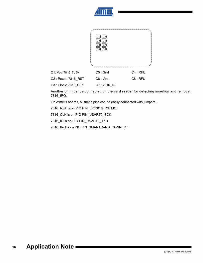
C1: Vcc: 7816_3V5V C5 : Gnd C4 : RFU
C2 : Reset: 7816_RST C6 : Vpp C8 : RFU
C3 : Clock: 7816_CLK C7 : 7816_IO
Another pin must be connected on the card reader for detecting insertion and removal:7816_IRQ.
On Atmel’s boards, all these pins can be easily connected with jumpers.
7816_RST is on PIO PIN_ISO7816_RSTMC
7816_CLK is on PIO PIN_USART0_SCK
7816_IO is on PIO PIN_USART0_TXD
7816_IRQ is on PIO PIN_SMARTCARD_CONNECT
C1
C2
C3
C4
C5
C6
C7
C8
166348A–ATARM–06-Jul-09
Application Note

Application Note
Revision History
Doc. Rev Date Comments Change Request Ref.
6348A 02-Jul-09 First issue
176348A–ATARM–06-Jul-09

Headquarters International
Atmel Corporation2325 Orchard ParkwaySan Jose, CA 95131USATel: 1(408) 441-0311Fax: 1(408) 487-2600
Atmel AsiaUnit 1-5 & 16, 19/FBEA Tower, Millennium City 5418 Kwun Tong RoadKwun Tong, KowloonHong KongTel: (852) 2245-6100Fax: (852) 2722-1369
Atmel EuropeLe Krebs8, Rue Jean-Pierre TimbaudBP 30978054 Saint-Quentin-en-Yvelines CedexFranceTel: (33) 1-30-60-70-00 Fax: (33) 1-30-60-71-11
Atmel Japan9F, Tonetsu Shinkawa Bldg.1-24-8 ShinkawaChuo-ku, Tokyo 104-0033JapanTel: (81) 3-3523-3551Fax: (81) 3-3523-7581
Product Contact
Web Sitewww.atmel.comwww.atmel.com/AT91SAM
Technical SupportAT91SAM SupportAtmel techincal support
Sales Contactswww.atmel.com/contacts/
Literature Requestswww.atmel.com/literature
Disclaimer: The information in this document is provided in connection with Atmel products. No license, express or implied, by estoppel or otherwise, to anyintellectual property right is granted by this document or in connection with the sale of Atmel products. EXCEPT AS SET FORTH IN ATMEL’S TERMS AND CONDI-TIONS OF SALE LOCATED ON ATMEL’S WEB SITE, ATMEL ASSUMES NO LIABILITY WHATSOEVER AND DISCLAIMS ANY EXPRESS, IMPLIED OR STATUTORYWARRANTY RELATING TO ITS PRODUCTS INCLUDING, BUT NOT LIMITED TO, THE IMPLIED WARRANTY OF MERCHANTABILITY, FITNESS FOR A PARTICULARPURPOSE, OR NON-INFRINGEMENT. IN NO EVENT SHALL ATMEL BE LIABLE FOR ANY DIRECT, INDIRECT, CONSEQUENTIAL, PUNITIVE, SPECIAL OR INCIDEN-TAL DAMAGES (INCLUDING, WITHOUT LIMITATION, DAMAGES FOR LOSS OF PROFITS, BUSINESS INTERRUPTION, OR LOSS OF INFORMATION) ARISING OUTOF THE USE OR INABILITY TO USE THIS DOCUMENT, EVEN IF ATMEL HAS BEEN ADVISED OF THE POSSIBILITY OF SUCH DAMAGES. Atmel makes norepresentations or warranties with respect to the accuracy or completeness of the contents of this document and reserves the right to make changes to specificationsand product descriptions at any time without notice. Atmel does not make any commitment to update the information contained herein. Unless specifically providedotherwise, Atmel products are not suitable for, and shall not be used in, automotive applications. Atmel’s products are not intended, authorized, or warranted for useas components in applications intended to support or sustain life.
© 2009 Atmel Corporation. All rights reserved. Atmel®, Atmel logo and combinations thereof, and others are registered trademarks or trade-marks of Atmel Corporation or its subsidiaries. ARM® and Thumb® are registered trademarks of ARM Ltd. Windows® and others are registeredtrademarks or trademarks of Microsoft Corporation in U.S. and/or other countries. Other terms and product names may be trademarks of others.
6348A–ATARM–06-Jul-09