


Languages
Pages
Legal

RCX221
EUR1127212
E100Ver. 2.12
User’s Manual
YAMAHA 2-AXIS ROBOT CONTROLLER

1
INTR
OD
UC
TION
IntroductionOur sincere thanks for your purchase of this YAMAHA robot controller.
This manual explains how to install and operate the YAMAHA robot controller. Be sure to
read this manual carefully as well as related manuals and comply with their instructions
for using the YAMAHA robot controller safely and correctly.
Refer to the "Programming Manual" that comes with the robot controller for detailed
information on robot programs.

BEFO
RE U
SING
THE R
OB
OT C
ON
TRO
LLER (B
E SUR
E TO R
EAD
THE FO
LLOW
ING
NO
TES)
2 3
Before using the robot controller (Be sure to read the following notes) Please be sure to perform the following tasks before using the robot controller.
Failing to perform these tasks may cause abnormal robot operation (vibration, noise) when
the power is turned on.
[1] When connecting the power supply to the robot controller
Always make a secure connection to the ground terminal on the robot controller to
ensure safety and prevent malfunctions due to noise.
Reference
Refer to "4. Connecting to the power" in Chapter 3, "Installation".
[2] When connecting robot cables to the robot controller
Be sure to keep robot cables separate from the robot controller power connection
lines and other equipment power lines. Using in close contact with lines carrying
power may cause malfunctions or abnormal operation.
2 3
OV
ERVIEW
OF TH
E RC
X SER
IES
Overview of the RCX seriesThe YAMAHA RCX series robot controllers were developed based on years of YAMAHA
experience and proven achievements in robotics and electronics. These controllers are
specifically designed to operate YAMAHA industrial robots efficiently and accurately.
Despite their compact size, the RCX series controllers operate efficiently as multi-axis
controllers with a variety of functions.
Major features and functions are:
1. Multi-task function
Up to 8 tasks* can be run simultaneously in a specified priority. (Low priority tasks
are halted while high priority tasks are run.)
I/O parallel processing and interrupt processing are also available, so that operational
efficiency of the total robot system including peripheral units is greatly improved.
(*: Refer to the programming manual for more details on multi-tasking.)
2. Robot language
The RCX series controller comes with a BASIC-like high-level robot language that
conforms to the industrial robot programming language SLIM *1. This robot language
allows easy programming even of complex movements such as multi-task operations
and uses a compiling method *2 for rapid execution of programs.
(*1: Standard Language for Industrial Manipulators)
(*2: This compiling method checks the syntax in a robot language program, converts
it into intermediate codes, and creates an execution file (object file) before actually
performing the program.)
3. Movement command
•Archmotion
Spatial movement during pick-and-place work can be freely set according to the
work environment. This is effective in reducing cycle time.
4. Maintenance
Software servo control provides unit standardization. This allows connection to most
YAMAHA robot models and simplifies maintenance.
5. CE marking *
As a YAMAHA robot series product, the RCX series robot controller is designed to
conform to machinery directives, low-voltage directives and EMC (Electromagnetic
compatibility) directives. In this case, the robot controller is set to operate under
"SAFE" mode. (* For CE marking compliance, see the CE marking supplement manual.)
This manual explains how to handle and operate the YAMAHA robot controllers
correctly and effectively, as well as I/O interface connections.
Read this manual carefully before installing and using the robot controller. Also refer
to the separate "Programming Manual" and "Robot User's Manual" as needed.

4
MEMO
i
GEN
ERA
L CO
NTEN
TS
General Contents
Introduction 1
Before using the robot controller (Be sure to read the following notes) 2
Overview of the RCX series 3
Chapter 1 USING THE ROBOT SAFELY
1. Safety information 1-1
2. Particularly important cautions 1-32.1 System design safety points 1-3
2.2 Installation safety points 1-4
2.3 Wiring safety points 1-5
2.4 Start-up and maintenance safety points 1-6
2.5 Safety precautions during robot operation 1-8
2.6 Precautions for disposal 1-8
3. Safety measures for robots 1-93.1 Safety measures for single-axis robots, Cartesian robots,
and pick & place robots 1-9
4. Motor overload precautions 1-9
5. Warning labels and marks 1-95.1 Warning labels 1-9
5.2 Warning marks 1-10
6. Industrial robot operating and maintenance personnel 1-11
7. Make daily and periodic inspections 1-11
8. Warranty 1-12
9. Operating environment 1-13
Chapter 2 SYSTEM OVERVIEW
1. System overview 2-11.1 Main system configuration 2-1
1.2 RCX22 series axis definition 2-2
2. Part names and functions 2-32.1 RCX221 (Maximum number of axes: 2) 2-3
2.2 RCX221HP (Maximum number of axes: 2) 2-3
GEN
ERA
L CO
NTEN
TS
ii iii
3. Control system 2-43.1 RCX221/RCX221HP 2-4
4. Optional devices 2-54.1 RPB programming box 2-5
4.2 I/O expansion 2-5
4.3 Regenerative unit 2-5
5. Basic sequence from installation to operation 2-6
Chapter 3 INSTALLATION
1. Unpacking 3-11.1 Packing box 3-1
1.2 Unpacking 3-1
2. Installing the robot controller 3-22.1 Installation conditions 3-2
2.2 Installation methods 3-4
3. Connector names 3-6
4. Connecting to the power 3-74.1 Connection example 3-7
4.2 Power supply and ground terminals 3-8
4.3 AC power connector wiring 3-9
4.4 Considering power capacity and generated heat amount 3-10
4.5 Installing an external leakage breaker 3-11
4.6 Installing a circuit protector 3-12
4.7 Installing an electromagnetic contactor 3-12
4.8 Installing a noise filter 3-13
4.9 Installing a surge absorber 3-14
5. Connecting the robot cables 3-15
6. Connecting the RPB programming box 3-16
7. I/O connections 3-17
8. Connecting a host computer 3-18
9. Connecting a regenerative unit 3-19
10. Precautions for cable routing and installation 3-2110.1 Wiring methods 3-21
10.2 Precautions for installation 3-23
10.3 Methods of preventing malfunctions 3-23
ii iii
GEN
ERA
L CO
NTEN
TS
11. Checking the robot controller operation 3-2411.1 Cable connection 3-24
11.2 Operation check 3-25
Chapter 4 OPERATION
1. Operation overview 4-1
2. The RCX robot controller 4-22.1 Part names 4-2
2.2 Main functions 4-2
3. RPB programming box 4-33.1 Part names 4-3
3.2 Main functions 4-3
3.3 Connection to the robot controller 4-4
3.4 Changing the RPB screen settings 4-5
4. Turning power on and off 4-6
5. Operation keys 4-85.1 RPB screen 4-8
5.2 Operation key layout 4-9
5.3 Basic key operation 4-10
5.4 Function keys 4-11
5.5 Control keys 4-13
5.6 Data keys 4-15
5.7 Other keys 4-15
6. Emergency stop 4-166.1 Emergency stop reset 4-17
7. Mode configuration 4-197.1 Basic operation modes 4-19
7.2 Other operation modes 4-20
7.3 Mode hierarchy 4-21
8. "SERVICE" mode 4-268.1 Operation device 4-26
8.2 Prohibition of "AUTO" mode operation 4-26
8.3 Hold-to-Run function 4-26
8.4 Limitations on robot operating speed 4-27
9. "AUTO" mode 4-289.1 Automatic operation 4-31
9.2 Stopping the program 4-32
GEN
ERA
L CO
NTEN
TS
iv v
9.3 Resetting the program 4-33
9.4 Switching task display 4-35
9.5 Switching the program 4-36
9.6 Changing the automatic movement speed 4-37
9.7 Executing the point trace 4-389.7.1 PTP motion mode 4-40
9.7.2 ARCH motion mode 4-41
9.7.3 Linear interpolation motion mode 4-43
9.8 Direct command execution 4-44
9.9 Break point 4-459.9.1 Setting break points 4-46
9.9.2 Deleting break points 4-47
9.10 Executing a step 4-48
9.11 Skipping a step 4-48
9.12 Executing the next step 4-49
10. "PROGRAM" mode 4-5010.1 Scrolling a program listing 4-51
10.2 Program editing 4-5210.2.1 Cursor movement 4-54
10.2.2 Insert/Overwrite mode switching 4-55
10.2.3 Inserting a line 4-56
10.2.4 Deleting a character 4-56
10.2.5 Deleting a line 4-56
10.2.6 User function key display 4-57
10.2.7 Quitting program editing 4-58
10.2.8 Specifying the copy/cut lines 4-58
10.2.9 Copying the selected lines 4-59
10.2.10 Cutting the selected lines 4-59
10.2.11 Pasting the data 4-60
10.2.12 Backspace 4-60
10.2.13 Line jump 4-61
10.2.14 Searching a character string 4-62
10.3 Directory 4-6310.3.1 Cursor movement 4-65
10.3.2 Registering a new program name 4-65
10.3.3 Directory information display 4-66
10.3.4 Copying a program 4-67
10.3.5 Erasing a program 4-68
10.3.6 Renaming a program 4-69
10.3.7 Changing the program attribute 4-70
10.3.8 Displaying object program information 4-71
10.3.9 Creating a sample program automatically 4-72
10.4 Compiling 4-74
10.5 Line jump and character string search 4-75
10.6 Registering user function keys 4-75
10.7 Resetting an error in the selected program 4-79
iv v
GEN
ERA
L CO
NTEN
TS
11. "MANUAL" mode 4-8011.1 Manual movement 4-82
11.2 Displaying and editing point data 4-8511.2.1 Point data input and editing 4-87
11.2.1.1 Restoring point data 4-88
11.2.2 Point data input by teaching 4-89
11.2.3 Point data input by direct teaching 4-91
11.2.4 Point jump display 4-92
11.2.5 Copying point data 4-93
11.2.6 Erasing point data 4-95
11.2.7 Point data trace 4-96
11.2.8 Point comment input and editing 4-96
11.2.8.1 Point comment input and editing 4-98
11.2.8.2 Point data input by teaching 4-98
11.2.8.3 Jump to a point comment 4-99
11.2.8.4 Copying a point comment 4-99
11.2.8.5 Erasing point comments 4-101
11.2.8.6 Point comment search 4-102
11.2.9 Point data error reset 4-103
11.3 Displaying, editing and setting pallet definitions 4-10411.3.1 Editing pallet definitions 4-106
11.3.1.1 Point setting in pallet definition 4-107
11.3.1.1.1 Editing the point in pallet definition 4-108
11.3.1.1.2 Setting the point in pallet definition by teaching 4-108
11.3.2 Pallet definition by teaching 4-109
11.3.3 Copying a pallet definition 4-112
11.3.4 Deleting a pallet definition 4-113
11.4 Changing the manual movement speed 4-114
11.5 Displaying, editing and setting shift coordinates 4-11511.5.1 Editing shift coordinates 4-117
11.5.1.1 Restoring shift coordinates 4-118
11.5.2 Editing the shift coordinate range 4-119
11.5.2.1 Restoring a shift coordinate range 4-121
11.5.3 Shift coordinate setting method 1 4-122
11.5.4 Shift coordinate setting method 2 4-125
11.6 Displaying, editing and setting hand definitions 4-12811.6.1 Editing hand definitions 4-131
11.6.1.1 Restoring hand definitions 4-132
11.6.2 Hand definition setting method 1 4-133
11.7 Changing the display units 4-135
11.8 Return-to-origin 4-13611.8.1 Return-to-origin operation 4-136
11.8.2 Semi-absolute 4-138
11.8.3 Checking the return-to-origin status 4-140
11.8.4 Return-to-origin on each axis 4-141
11.8.5 Return-to-origin on all axes 4-143
11.9 Setting the standard coordinates 4-145
11.10 Executing the user function keys 4-146

GEN
ERA
L CO
NTEN
TS
vi vii
12. "SYSTEM" mode 4-14712.1 Parameters 4-149
12.1.1 Robot parameters 4-151
12.1.2 Axis parameters 4-155
12.1.3 Other parameters 4-174
12.1.4 Parameters for option boards 4-190
12.1.4.1 Option DIO setting 4-192
12.1.4.2 Serial IO setting 4-193
12.1.4.3 Setting the network parameters 4-198
12.2 Communication parameters 4-200
12.3 OPTION parameters 4-20912.3.1 Setting the area check output 4-210
12.3.2 Setting the "SERVICE" mode 4-219
12.3.2.1 Saving the "SERVICE" mode parameters 4-225
12.3.2.2 Help display in "SERVICE" mode 4-226
12.3.3 SIO settings 4-227
12.3.4 Double-carrier setting 4-230
12.3.4.1 Before using a double-carrier 4-230
12.3.4.2 Setting the double-carrier parameters 4-231
12.4 Initialization 4-23412.4.1 Initializing the parameters 4-235
12.4.2 Initializing the memory 4-236
12.4.3 Initializing the communication parameters 4-237
12.4.4 Clock setting 4-238
12.4.5 System generation 4-239
12.5 Self diagnosis 4-24012.5.1 Controller check 4-241
12.5.2 Error history display 4-242
12.5.3 Displaying the total operation time 4-243
12.5.4 System error details display 4-244
12.6 Backup processes 4-24512.6.1 SD memory card 4-246
12.6.1.1 Loading files 4-248
12.6.1.2 Saving files 4-250
12.6.1.3 Deleting files 4-252
12.6.1.4 Previewing files 4-253
12.6.2 Internal flash ROM 4-254
12.6.2.1 Loading files 4-255
12.6.2.2 Saving files 4-257
12.6.2.3 Initializing the files 4-258
13. "MONITOR" mode 4-259
14. "UTILITY" mode 4-26214.1 Canceling emergency stop; Motor power and servo on/off 4-264
14.1.1 Canceling emergency stop 4-264
14.1.2 Motor power and servo on/off 4-265
14.2 Enabling/disabling the sequence execution flag 4-267
14.3 Resetting the output ports 4-268
vi vii
GEN
ERA
L CO
NTEN
TS
14.4 Changing the execution level 4-26914.4.1 Changing the execution level 4-270
14.4.2 Displaying the Help message 4-271
14.5 Changing the access level (operation level) 4-27214.5.1 Entering the password 4-273
14.5.2 Changing the access level 4-274
14.5.3 Displaying the Help message 4-275
Chapter 5 PARALLEL I/O INTERFACE
1. Standard I/O interface overview 5-11.1 ID setting 5-2
1.2 Connector I/O signals 5-3
1.3 Connector pin numbers 5-6
1.4 Connecting the power supply 5-71.4.1 NPN/PNP power connector wiring 5-8
1.5 Typical input signal connection 5-9
1.6 Typical output signal connection 5-10
1.7 Dedicated I/O signals 5-111.7.1 Dedicated input signals 5-11
1.7.2 Dedicated output signals 5-13
1.8 General-purpose I/O signals 5-151.8.1 General-purpose output reset 5-15
1.9 Dedicated I/O signal timing charts 5-161.9.1 Turning the power on 5-16
1.9.2 Emergency stop and servo ON 5-18
1.9.3 Return-to-origin 5-19
1.9.4 Mode switching 5-20
1.9.5 Automatic operation 5-21
2. Ratings 5-22
3. Precautions 5-23
Chapter 6 SAFETY I/O INTERFACE
1. SAFETY I/O interface overview 6-11.1 Power 6-1
1.2 Connector I/O signals 6-2
1.3 Connector terminal numbers 6-3
1.4 Emergency stop input signal connections 6-4
1.5 Dedicated input signal connections 6-10
1.6 Dedicated output signal connections 6-11
1.7 Input signal description 6-13
1.8 Meaning of output signals 6-14

GEN
ERA
L CO
NTEN
TS
viii ix
Chapter 7 RS-232C INTERFACE
1. Communication overview 7-1
2. Communication function overview 7-2
3. Communication specifications 7-33.1 Connector 7-3
3.2 Transmission mode and communication parameters 7-5
3.3 Communication flow control 7-63.3.1 Flow control during transmit 7-6
3.3.2 Flow control during receive 7-6
3.4 Other caution items 7-7
3.5 Character code table 7-9
3.6 Connecting to a PC 7-10
Chapter 8 SPECIFICATIONS
1. Controller basic specifications 8-1
2. Controller basic functions 8-3
3. Controller external view 8-43.1 RCX221 external view 8-4
3.2 RCX221HP external view 8-5
4. RPB basic specifications and external view 8-6
Chapter 9 TROUBLESHOOTING
1. Error Messages 9-11.1 Robot controller error messages 9-1
[ 0] Warnings and messages 9-3
[ 1] Warnings (error history entry) 9-5
[ 2] Robot operating area errors 9-6
[ 3] Program file operating errors 9-9
[ 4] Data entry and edit errors 9-12
[ 5] Robot language syntax (compiling) errors 9-12
[ 6] Robot language execution errors 9-21
[ 9] Memory errors 9-26
[10] System setting or hardware errors 9-29
[12] I/O and option board errors 9-31
[13] RPB errors 9-35
[14] RS-232C communication errors 9-36
[15] Memory card errors 9-38
[17] Motor control errors 9-40
[19] YC-Link (SR1) related error 9-47
[21] Major software errors 9-53
[22] Major hardware errors 9-55

viii ix
GEN
ERA
L CO
NTEN
TS
1.2 RPB Error Messages 9-61
2. Troubleshooting 9-632.1 When trouble occurs 9-63
2.2 Acquiring error information 9-642.2.1 Acquiring information from the RPB 9-64
2.2.2 Acquiring information from the RS-232C 9-64
2.3 Troubleshooting checkpoints 9-65

x
MEMO

Chapter 1 USING THE ROBOT SAFELY
Contents
1. Safety information 1-1
2. Particularly important cautions 1-32.1 System design safety points 1-3
2.2 Installation safety points 1-4
2.3 Wiring safety points 1-5
2.4 Start-up and maintenance safety points 1-6
2.5 Safety precautions during robot operation 1-8
2.6 Precautions for disposal 1-8
3. Safety measures for robots 1-93.1 Safety measures for single-axis robots, Cartesian
robots, and pick & place robots 1-9
4. Motor overload precautions 1-9
5. Warning labels and marks 1-95.1 Warning labels 1-9
5.2 Warning marks 1-10
6. Industrial robot operating and maintenance personnel 1-11
7. Make daily and periodic inspections 1-11
8. Warranty 1-12
9. Operating environment 1-13

1-1

1-1
Chapter
1
USIN
G TH
E RO
BO
T SAFELY
1. Safety informationBefore using the YAMAHA robot controller, be sure to read this manual and related
manuals, and follow their instructions to use the robot controller safely and correctly.
Warnings and cautions listed in this manual relate to YAMAHA robot controllers. To
ensure safety of the user's final system that includes YAMAHA robots and controllers,
please take appropriate safety measures as required by the user's individual system.
Industrial robots are highly programmable machines that provide a large degree of
freedom in movement. To use YAMAHA robots and controllers safely and correctly, be
sure to comply with the safety instructions and precautions described in this chapter.
Failure to take necessary safety measures or incorrect handling may result not only in
trouble or damage to the robot and controller, but also in serious accidents involving
injury or death to personnel (robot installer, operator, or service personnel).
This manual describes safety precautions and operating points using the following symbols
and signal words.
wDANGER "DANGER" INDICATES AN IMMINENTLY HAzARDOUS SITUATION WHICH, IF NOT AVOIDED, WILL RESULT IN DEATH OR SERIOUS INjURY.
wWARNING "WARNING" INDICATES A POTENTIALLY HAzARDOUS SITUATION WHICH, IF NOT AVOIDED, COULD RESULT IN DEATH OR SERIOUS INjURY.
cCAUTION "CAUTION" indicates a potentially hazardous situation which, if not avoided, could result in minor or moderate injury or damage to the equipment or loss of data.
n NOTE
Explains key points in the operation in a simple and clear manner.
1. Safety information
1-2
Chapter
1
USIN
G TH
E RO
BO
T SAFELY
1-3
Use any of the following approaches to this manual when installing, operating and
adjusting the YAMAHA robot and/or controller so that you can quickly refer to this manual
when needed.
1. Keep the printed version of this manual (available for an additional fee) handy for
ready reference.
2. View the CD-ROM version of this manual on your PC screen.
3. Print out the necessary pages of this manual from the CD-ROM and keep them
handy for ready reference.
To use YAMAHA robots and controllers safely and correctly, always comply with the
safety rules and instructions.
Please note, however, this user's manual cannot cover all items regarding safety. So it is
extremely important that the operator or user have knowledge of safety and make correct
decisions regarding safety.
1. Safety information

1-2 1-3
Chapter
1
USIN
G TH
E RO
BO
T SAFELY
2. Particularly important cautionsParticularly important cautions for handling and operating the robot and controller are
described below. Additional cautions are also described in each chapter. Be sure to
comply with those instructions to ensure safety.
2.1 System design safety points
wDANGER • YAMAHArobotcontrollersAndrobotsAredesignedAnd MANUFACTURED FOR GENERAL-PURPOSE INDUSTRIAL EqUIPMENT. THEY SHOULD NOT BE USED IN THE FOLLOWING APPLICATIONS: • MedicAlequipMentorsYsteMswHicHwillAffectHuMAnlife • equipMentdesignedtocArrYortrAnsportpersons • equipMentorsYsteMswHicHwillseriouslYAffectsocietYor PUBLIC POLICY • USE IN ENVIRONMENTS SUBjECT TO VIBRATION, SUCH AS VEHICLES AND SHIPS • EACH ROBOT CONTROLLER HAS AN EMERGENCY STOP INPUT TERMINAL TO TRIGGER EMERGENCY STOP. USING THIS TERMINAL, CONFIGURE A SAFETY CIRCUIT SO THAT THE SYSTEM INCLUDING THE ROBOT CONTROLLER WILL WORk SAFELY.
wWARNING • tocHecktHeoperAtingstAtusoftHerobotcontroller,referto THIS MANUAL AND RELATED USER'S MANUAL. BUILD THE SYSTEM INCLUDING THE ROBOT CONTROLLER SO THAT IT WILL ALWAYS WORk SAFELY. • instAllAsignAlligHt(signAltower,etc.)AtAneAsY-to-see POSITION SO THAT THE OPERATOR WILL kNOW THE STOP STATUS OF THE ROBOT (TEMPORARY STOP, EMERGENCY STOP, ERROR STOP, ETC.).
cCAUTION • Do not bundle control lines or communication cables together or in close contact with the main power supply circuit or power lines. As a general rule, separate them by at least 100mm. Failure to follow this instruction may cause malfunctions due to noise.
2. Particularly important cautions

1-4
Chapter
1
USIN
G TH
E RO
BO
T SAFELY
1-5
2.2 Installation safety points
wWARNING • AlwAYsgroundtHegroundterMinAloftHepowerterMinAlblock TO AVOID ELECTRICAL SHOCk. • securelYinstAlltHeconnectorsintotHerobotcontroller,And WHEN WIRING THE CONNECTORS, MAkE THE CRIMP, PRESS-CONTACT OR SOLDER CONNECTIONS CORRECTLY, USING THE TOOL SPECIFIED BY THE MANUFACTURER. • AlwAYssHutoffAllpHAsesoftHepowersupplYexternAllYbefore STARTING INSTALLATION OR WIRING WORk. FAILURE TO SHUT OFF ALL PHASES MAY CAUSE ELECTRICAL SHOCk OR PRODUCT DAMAGE. • YAMAHArobotsAndrobotcontrollersArenotdesignedtobe EXPLOSION-PROOF. DO NOT USE THEM IN LOCATIONS EXPOSED TO INFLAMMABLE GASES, GASOLINE OR SOLVENT THAT COULD CAUSE EXPLOSION OR FIRE. FAILURE TO OBSERVE THIS INSTRUCTION MAY CAUSE SERIOUS ACCIDENTS INVOLVING INjURY OR DEATH, OR LEAD TO FIRE. • usetHerobotcontrollerwitHintHeenvironMentspecificAtions LISTED IN THIS MANUAL. USING THE CONTROLLER IN AN ENVIRONMENT OUTSIDE THE SPECIFICATION RANGE MAY CAUSE ELECTRICAL SHOCk, MALFUNCTIONS, PRODUCT DAMAGE OR DETERIORATED PERFORMANCE. • instAlltHerobotcontrollerAndprogrAMMingboxAtA LOCATION OUTSIDE THE ROBOT'S WORkING ENVELOPE YET WHERE IT IS EASY TO OPERATE THE ROBOT AND VIEW ITS MOTION. • instAlltHecontrollerinlocAtionswitHenougHspAcetoperforM WORk (TEACHING, INSPECTION, ETC.) SAFELY. LIMITED SPACE NOT ONLY MAkES IT DIFFICULT TO PERFORM WORk, BUT CAN ALSO BE A CAUSE OF INjURY. • instAlltHerobotcontrollerinAstAble,levellocAtionAnd SECURE IT FIRMLY. AVOID INSTALLING THE ROBOT CONTROLLER UPSIDE DOWN OR IN A TILTED POSITION. • providesufficientcleArAnceAroundtHerobotcontrollerfor GOOD VENTILATION. POOR VENTILATION MAY CAUSE MALFUNCTION, BREAkDOWN OR FIRE. • neverdirectlYtoucHtHeconductivesectionsAndelectronic PARTS OTHER THAN THE CONNECTORS, ROTARY SWITCHES, AND DIP SWITCHES ON THE OUTSIDE PANEL OF THE ROBOT CONTROLLER. • securelYtigHtentHescrewsontHel-sHApedbrAcketstoinstAlltHe ROBOT CONTROLLER. IF NOT SECURELY TIGHTENED, THE SCREWS MAY BECOME LOOSE CAUSING THE CONTROLLER TO DROP. • securelYinstAlleAcHconnectioncAbleconnectorintotHe RECEPTACLES OR SOCkETS. POOR CONNECTIONS MAY CAUSE EqUIPMENT MALFUNCTIONS.
2. Particularly important cautions

1-4 1-5
Chapter
1
USIN
G TH
E RO
BO
T SAFELY
2.3 Wiring safety points
wWARNING • AlwAYssHutoffAllpHAsesoftHepowersupplYexternAllYbefore STARTING INSTALLATION OR WIRING WORk. FAILURE TO SHUT OFF ALL PHASES MAY CAUSE ELECTRICAL SHOCk OR PRODUCT DAMAGE.
cCAUTION • Makesurethatnoforeignmattersuchascuttingchipsorwirescraps enter the robot controller. Malfunctions, breakdown or fire may result if they have entered. • Alwaysstorethecablesconnectedtotherobotcontrollerinaconduitor clamp them securely in place. If the cables are not stored in a conduit or properly clamped, excessive play or movement or mistakenly pulling on the cable may damage the connector or cables, and poor cable contact may cause equipment malfunctions. • donotmodifythecablesanddonotplaceanyheavyobjectonthem. Handle them carefully to avoid damage. Damaged cables may cause malfunction or electrical shock. • ifthereisapossibilitythatthecablesconnectedtotherobotcontroller may be damaged, protect them with a cover, etc. • donotapplyexcessiveloadsorimpactstotheconnectorswhenmaking cable connections. The connector pins may become bent or the internal PC board may be damaged. • whendisconnectingthecablefromtherobotcontroller,detachby gripping the connector itself and not by tugging on the cable. Loosen the screws on the connector (if fastened with the screws), and then disconnect the cable. Detaching by pulling on the cable itself may damage the connector or cables, and poor cable contact may cause equipment malfunctions.
2. Particularly important cautions
1-6
Chapter
1
USIN
G TH
E RO
BO
T SAFELY
1-7
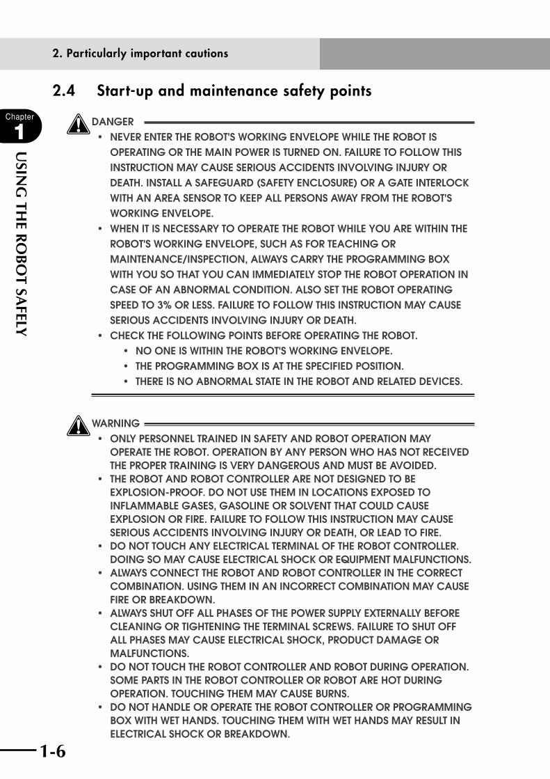
2.4 Start-up and maintenance safety points
wDANGER • neverentertHerobot'sworkingenvelopewHiletHerobotis OPERATING OR THE MAIN POWER IS TURNED ON. FAILURE TO FOLLOW THIS INSTRUCTION MAY CAUSE SERIOUS ACCIDENTS INVOLVING INjURY OR DEATH. INSTALL A SAFEGUARD (SAFETY ENCLOSURE) OR A GATE INTERLOCk WITH AN AREA SENSOR TO kEEP ALL PERSONS AWAY FROM THE ROBOT'S WORkING ENVELOPE. • wHenitisnecessArYtooperAtetHerobotwHileYouArewitHintHe ROBOT'S WORkING ENVELOPE, SUCH AS FOR TEACHING OR MAINTENANCE/INSPECTION, ALWAYS CARRY THE PROGRAMMING BOX WITH YOU SO THAT YOU CAN IMMEDIATELY STOP THE ROBOT OPERATION IN CASE OF AN ABNORMAL CONDITION. ALSO SET THE ROBOT OPERATING SPEED TO 3% OR LESS. FAILURE TO FOLLOW THIS INSTRUCTION MAY CAUSE SERIOUS ACCIDENTS INVOLVING INjURY OR DEATH. • cHecktHefollowingpointsbeforeoperAtingtHerobot. • nooneiswitHintHerobot'sworkingenvelope. • tHeprogrAMMingboxisAttHespecifiedposition. • tHereisnoAbnorMAlstAteintHerobotAndrelAteddevices.
wWARNING • onlYpersonneltrAinedinsAfetYAndrobotoperAtionMAY OPERATE THE ROBOT. OPERATION BY ANY PERSON WHO HAS NOT RECEIVED THE PROPER TRAINING IS VERY DANGEROUS AND MUST BE AVOIDED. • tHerobotAndrobotcontrollerArenotdesignedtobe EXPLOSION-PROOF. DO NOT USE THEM IN LOCATIONS EXPOSED TO INFLAMMABLE GASES, GASOLINE OR SOLVENT THAT COULD CAUSE EXPLOSION OR FIRE. FAILURE TO FOLLOW THIS INSTRUCTION MAY CAUSE SERIOUS ACCIDENTS INVOLVING INjURY OR DEATH, OR LEAD TO FIRE. • donottoucHAnYelectricAlterMinAloftHerobotcontroller. DOING SO MAY CAUSE ELECTRICAL SHOCk OR EqUIPMENT MALFUNCTIONS. • AlwAYsconnecttHerobotAndrobotcontrollerintHecorrect COMBINATION. USING THEM IN AN INCORRECT COMBINATION MAY CAUSE FIRE OR BREAkDOWN. • AlwAYssHutoffAllpHAsesoftHepowersupplYexternAllYbefore CLEANING OR TIGHTENING THE TERMINAL SCREWS. FAILURE TO SHUT OFF ALL PHASES MAY CAUSE ELECTRICAL SHOCk, PRODUCT DAMAGE OR MALFUNCTIONS. • donottoucHtHerobotcontrollerAndrobotduringoperAtion. SOME PARTS IN THE ROBOT CONTROLLER OR ROBOT ARE HOT DURING OPERATION. TOUCHING THEM MAY CAUSE BURNS. • donotHAndleoroperAtetHerobotcontrollerorprogrAMMing BOX WITH WET HANDS. TOUCHING THEM WITH WET HANDS MAY RESULT IN ELECTRICAL SHOCk OR BREAkDOWN.
2. Particularly important cautions
1-6 1-7
Chapter
1
USIN
G TH
E RO
BO
T SAFELY
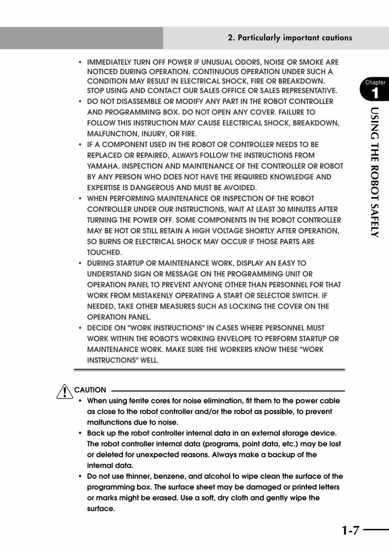
• iMMediAtelYturnoffpowerifunusuAlodors,noiseorsMokeAre NOTICED DURING OPERATION. CONTINUOUS OPERATION UNDER SUCH A CONDITION MAY RESULT IN ELECTRICAL SHOCk, FIRE OR BREAkDOWN. STOP USING AND CONTACT OUR SALES OFFICE OR SALES REPRESENTATIVE. • donotdisAsseMbleorModifYAnYpArtintHerobotcontroller AND PROGRAMMING BOX. DO NOT OPEN ANY COVER. FAILURE TO FOLLOW THIS INSTRUCTION MAY CAUSE ELECTRICAL SHOCk, BREAkDOWN, MALFUNCTION, INjURY, OR FIRE. • ifAcoMponentusedintHerobotorcontrollerneedstobe REPLACED OR REPAIRED, ALWAYS FOLLOW THE INSTRUCTIONS FROM YAMAHA. INSPECTION AND MAINTENANCE OF THE CONTROLLER OR ROBOT BY ANY PERSON WHO DOES NOT HAVE THE REqUIRED kNOWLEDGE AND EXPERTISE IS DANGEROUS AND MUST BE AVOIDED. • wHenperforMingMAintenAnceorinspectionoftHerobot CONTROLLER UNDER OUR INSTRUCTIONS, WAIT AT LEAST 30 MINUTES AFTER TURNING THE POWER OFF. SOME COMPONENTS IN THE ROBOT CONTROLLER MAY BE HOT OR STILL RETAIN A HIGH VOLTAGE SHORTLY AFTER OPERATION, SO BURNS OR ELECTRICAL SHOCk MAY OCCUR IF THOSE PARTS ARE TOUCHED. • duringstArtuporMAintenAncework,displAYAneAsYto UNDERSTAND SIGN OR MESSAGE ON THE PROGRAMMING UNIT OR OPERATION PANEL TO PREVENT ANYONE OTHER THAN PERSONNEL FOR THAT WORk FROM MISTAkENLY OPERATING A START OR SELECTOR SWITCH. IF NEEDED, TAkE OTHER MEASURES SUCH AS LOCkING THE COVER ON THE OPERATION PANEL. • decideon"workinstructions"incAseswHerepersonnelMust WORk WITHIN THE ROBOT'S WORkING ENVELOPE TO PERFORM STARTUP OR MAINTENANCE WORk. MAkE SURE THE WORkERS kNOW THESE "WORk INSTRUCTIONS" WELL.
cCAUTION • whenusingferritecoresfornoiseelimination,fitthemtothepowercable as close to the robot controller and/or the robot as possible, to prevent malfunctions due to noise. • backuptherobotcontrollerinternaldatainanexternalstoragedevice. The robot controller internal data (programs, point data, etc.) may be lost or deleted for unexpected reasons. Always make a backup of the internal data. • donotusethinner,benzene,andalcoholtowipecleanthesurfaceofthe programming box. The surface sheet may be damaged or printed letters or marks might be erased. Use a soft, dry cloth and gently wipe the surface.
2. Particularly important cautions

1-8
Chapter
1
USIN
G TH
E RO
BO
T SAFELY
1-9
• donotuseahardorpointedobjecttooperatethekeysonthe programming box. Malfunction or breakdown may result if the keys are damaged. Use your fingers to operate the keys. • donotinsertanysdmemorycardotherthanspecifiedintothesd memory card slot of the programming box. Malfunction or breakdown may result if a wrong memory card is used.
2.5 Safety precautions during robot operation
wDANGER • neverentertHerobot'sworkingenvelopewHiletHerobotis OPERATING OR THE MAIN POWER IS TURNED ON. FAILURE TO FOLLOW THIS INSTRUCTION MAY CAUSE SERIOUS ACCIDENTS INVOLVING INjURY OR DEATH. INSTALL A SAFEGUARD (SAFETY ENCLOSURE) OR A GATE INTERLOCk WITH AN AREA SENSOR TO kEEP ALL PERSONS AWAY FROM THE ROBOT'S WORkING ENVELOPE. • wHenitisnecessArYtooperAtetHerobotwHileYouArewitHintHe ROBOT'S WORkING ENVELOPE, SUCH AS FOR TEACHING OR MAINTENANCE/INSPECTION, ALWAYS CARRY THE PROGRAMMING BOX WITH YOU SO THAT YOU CAN IMMEDIATELY STOP THE ROBOT OPERATION IN CASE OF AN ABNORMAL CONDITION. ALSO SET THE ROBOT OPERATING SPEED TO 3% OR LESS. FAILURE TO FOLLOW THIS INSTRUCTION MAY CAUSE SERIOUS ACCIDENTS INVOLVING INjURY OR DEATH.
wWARNING • onlYpersonneltrAinedinsAfetYAndrobotoperAtionMAY OPERATE THE ROBOT. OPERATION BY ANY PERSON WHO HAS NOT RECEIVED THE PROPER TRAINING IS VERY DANGEROUS AND MUST BE AVOIDED.
2.6 Precautions for disposal
cCAUTION • whendisposingofthisproductdiscarditasindustrialwaste.take appropriate measures in compliance with legal regulations in your country or entrust its proper disposal to a company authorized to handle industrial waste.
2. Particularly important cautions
1-8 1-9
Chapter
1
USIN
G TH
E RO
BO
T SAFELY
3. Safety measures for robots
3. Safety measures for robots
3.1 Safety measures for single-axis robots, Cartesian robots, and pick & place robots(1) Protective measures against electrical shock:
Use the protective ground terminal to ensure safety.
Refer to the robot user's manual for details.
4. Motor overload precautionsSince abnormal operation (such as overload) of the motor is detected by software, the
controller parameters must be set correctly to match the motor type used in the robot
connected to the controller.
Prior to shipping, the controller parameters are preset to match the robot model to be
used. However, please check the robot model again when connecting it to the controller.
5. Warning labels and marks
5.1 Warning labelsThe warning labels shown below are affixed to the controller. To use the YAMAHA robot
and controller safely and correctly, be sure to observe the instructions and caution on the
labels.
(1) "Read Instruction Manual" label
取扱説明書参照
READ INSTRUCTIONMANUAL
This label means that important information you must know is described in the manual. Before using the controller, be sure to read this manual carefully. When in particular configuring an external safety circuit or connecting a power supply to the controller, read this manual carefully and follow the instructions. Connectors have a particular orientation, so insert each connector in the correct direction.

1-10
Chapter
1
USIN
G TH
E RO
BO
T SAFELY
1-11
5.2 Warning marksThe following warning marks are shown on the controller. To use the YAMAHA robot
and controller safely and correctly, be sure to observe the instructions and caution of the
marks.
(1) "Electric Hazard" mark
This mark indicates that a high voltage is present.
This mark warns you of possible electrical shock. Do not touch the terminal block
and connectors to avoid electrical shock.
(2) "CAUTION" mark
!This label means that important information you must know is described in the
manual.
Before using the controller, be sure to read this manual carefully.
When in particular configuring an external safety circuit or connecting a power
supply to the controller, read this manual carefully and follow the instructions.
Connectors have a particular orientation, so insert each connector in the correct
direction.
(3) "High Temperature Hazard" mark
Indicates that the area around this mark may become very hot.
Heatsinks and regenerative unit become hot during and shortly after operation. Do
not touch them to avoid burns.
5. Warning labels and marks

1-10 1-11
Chapter
1
USIN
G TH
E RO
BO
T SAFELY
6. Industrial robot operating and maintenance personnelOperators or persons who handle the robot such as for teaching, programming, movement
check, inspection, adjustment, and repair must receive appropriate training and also have
the skills needed to perform the job correctly and safely. They must read the user's manual
carefully to understand its contents before attempting the robot operation.
Tasks related to industrial robots (teaching, programming, movement check, inspection,
adjustment, repair, etc.) must be performed by qualified persons who meet requirements
established by local regulations and safety standards for industrial robots.
7. Make daily and periodic inspectionsAlways make sure that daily and periodic inspections are performed, and make a pre-work
check to ensure there are no problems with the robot or related equipment. If a problem
or abnormality is found, then promptly repair it or take other measures as necessary.
6. Industrial robot operating and maintenance personnel

1-12
Chapter
1
USIN
G TH
E RO
BO
T SAFELY
1-13
8. WarrantyFor information on the warranty period and terms, please contact our distributor where you purchased the product.
■ This warranty does not cover any failure caused by:1. Installation, wiring, connection to other control devices, operating methods,
inspection or maintenance that does not comply with industry standards or instructions specified in the YAMAHA manual;
2. Usage that exceeded the specifications or standard performance shown in the YAMAHA manual;
3. Product usage other than intended by YAMAHA;
4. Storage, operating conditions and utilities that are outside the range specified in the manual;
5. Damage due to improper shipping or shipping methods;
6. Accident or collision damage;
7. Installation of other than genuine YAMAHA parts and/or accessories;
8. Modification to original parts or modifications not conforming to standard specifications designated by YAMAHA, including customizing performed by YAMAHA in compliance with distributor or customer requests;
9. Pollution, salt damage, condensation;
10. Fires or natural disasters such as earthquakes, tsunamis, lightning strikes, wind and flood damage, etc;
11. Breakdown due to causes other than the above that are not the fault or responsibility of YAMAHA;
■ The following cases are not covered under the warranty: 1. Products whose serial number or production date (month & year) cannot be
verified.
2. Changes in software or internal data such as programs or points that were created or changed by the customer.
3. Products whose trouble cannot be reproduced or identified by YAMAHA.
4. Products utilized, for example, in radiological equipment, biological test equipment applications or for other purposes whose warranty repairs are judged as hazardous by YAMAHA.
THE WARRANTY STATED HEREIN PROVIDED BY YAMAHA ONLY COVERS DEFECTS IN PRODUCTS AND PARTS SOLD BY YAMAHA TO DISTRIBUTORS UNDER THIS AGREEMENT. ANY AND ALL OTHER WARRANTIES OR LIABILITIES, EXPRESS OR IMPLIED, INCLUDING BUT NOT LIMITED TO ANY IMPLIED WARRANTIES OF MERCHANTABILITY OR FITNESS FOR A PARTICULAR PURPOSE ARE HEREBY EXPRESSLY DISCLAIMED BY YAMAHA. MOREOVER, YAMAHA SHALL NOT BE HELD RESPONSIBLE FOR CONSEQUENT OR INDIRECT DAMAGES IN ANY MANNER RELATING TO THE PRODUCT.
8. Warranty
Ver.1.00_201205
1-12 1-13
Chapter
1
USIN
G TH
E RO
BO
T SAFELY
9. Operating environmentOperating temperature
Operating temperature 0°C to 40°C
The ambient temperature should be maintained within a range of 0 to 40°C in
order to guarantee continuous operation of the robot controller that meets the
initial specifications. If the robot controller is installed in a narrow space, then heat
generated from the controller itself and from peripheral equipment may drive the
temperature above the allowable operating temperature range. This may result in
thermal runaway or malfunctions and may lower component performance along with
shortening their useful service life. So be sure to install the controller in locations
with a vent having a natural air flow. If this proves insufficient, provide forced air-
cooling.
Storage temperature
Storage temperature -10°C to 65°C
The controller should be stored in a location at an ambient temperature between -10
and +65°C when not being used. If the robot controller is stored in a location at high
temperatures for extended periods, deterioration of the electronic components may
occur and the memory backup time may decrease.
Operating humidity
Operating humidity 35% to 85% RH (no condensation)
The ambient humidity should be 35% to 85% RH (no condensation) in order
to guarantee continuous operation of the robot controller that meets the initial
specifications. Installing the robot controller inside an air-conditioned or cooled
housing is recommended when the ambient humidity is high or when condensation
occurs.
Storage humidity
Storage humidity Below 95% RH (no condensation)
The controller should be stored in a location at an ambient humidity below 95% RH
(no condensation) when not being used. If the robot controller is stored in a location
at high humidity for an extended period of time, rust may form on the electronic
components in the robot controller.
Vibration and shock Do not apply strong shocks to the controller. Do not install the controller in locations
subject to large vibrations or shocks. The controller may malfunction or break down
if subjected to large vibrations or shocks.
Environments
The controller is not designed to meet explosion-proof, dust-proof, and drip-proof
specifications, and so do not use it in the following locations. If used in these
9. Operating environment
1-14
Chapter
1
USIN
G TH
E RO
BO
T SAFELY
locations, component corrosion, improper installation, or fire may result.
1) Environments containing combustible gases or dust particles, or flammable liquids, etc.
2) Environments where conductive substances such as metal cutting chips are present.
3) Environments where water, cutting water, oils, dust, metal particles, or organic solvents are present.
4) Environments containing corrosive gases or substances such as acid or alkali.
5) Environments containing mist such as cutting fluids or grinding fluids.
If using the controller in locations where dust particles of gases may generate, it is recommended to install the controller in a box with a cooling unit.
Installation location Always install the robot controller indoors, at a height of less than 1000 meters above
sea level.
Install the controller in a control panel with a structure that does not allow water, oil,
carbon or dust particles to penetrate it.
Do not install the controller in the following locations:
1) Near devices which may be a source of electrical noise, such as large inverters, high-output high-frequency generators, large contactors, and welding machines.
2) Locations where electrostatic noise is generated.
3) Locations subject to radio frequency interference.
4) Locations where there is a possibility of exposure to radioactivity.
5) Locations where dangerous items such as ignitable, flammable or explosive materials are present.
6) Near combustible materials.
7) Environments exposed to direct sunlight.
8) Narrow space where tasks (teaching, inspections, etc.) cannot be performed
safely.
9. Operating environment

Chapter 2 SYSTEM OVERVIEW
Contents
1. System overview 2-11.1 Main system configuration 2-1
1.2 RCX22 series axis definition 2-2
2. Part names and functions 2-32.1 RCX221 (Maximum number of axes: 2) 2-3
2.2 RCX221HP (Maximum number of axes: 2) 2-3
3. Control system 2-43.1 RCX221/RCX221HP 2-4
4. Optional devices 2-54.1 RPB programming box 2-5
4.2 I/O expansion 2-5
4.3 Regenerative unit 2-5
5. Basic sequence from installation to operation 2-6

2-1
2-1
Chapter
2
SYSTEM
OV
ERVIEW
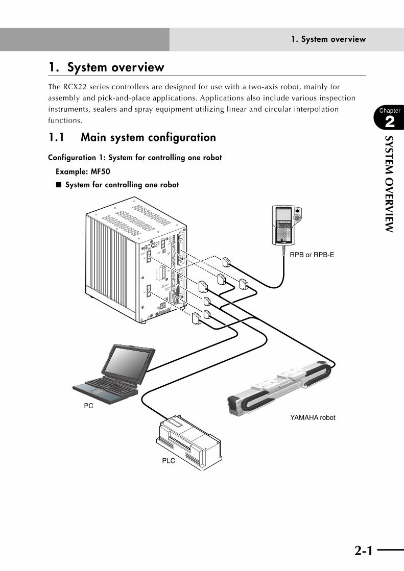
1. System overviewThe RCX22 series controllers are designed for use with a two-axis robot, mainly for
assembly and pick-and-place applications. Applications also include various inspection
instruments, sealers and spray equipment utilizing linear and circular interpolation
functions.
1.1 Main system configuration
Configuration 1: System for controlling one robot
Example: MF50
■ System for controlling one robot
RCX221
XM
YM
MOTOR
RGEN
TEMP
ACIN
N
L
L1
N1
SAFETY
SRV
ERR
RPB
ROBI/O
SD/COM
RDY
E-STOP
EXT.E-STOP
PIN11-12
OP.1
OP.2
!
YAMAHA robot
PLC
RPB or RPB-E
PC
1. System overview
2-2
Chapter
2
SYSTEM
OV
ERVIEW
2-3
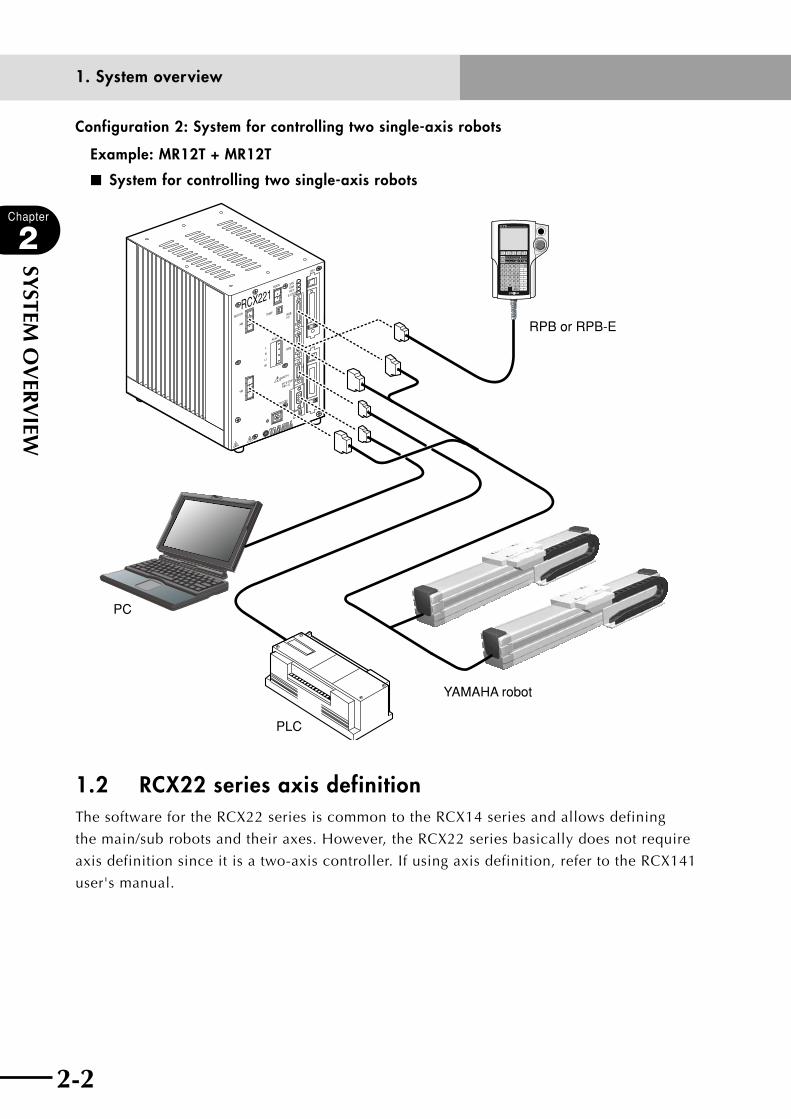
Configuration 2: System for controlling two single-axis robots
Example: MR12T + MR12T
■ System for controlling two single-axis robots
RCX221
XM
YM
MOTOR
RGEN
TEMP
ACIN
N
L
L1
N1
SAFETY
SRV
ERR
RPB
ROBI/O
SD/COM
RDY
E-STOP
EXT.E-STOP
PIN11-12
OP.1
OP.2
!
YAMAHA robot
PLC
RPB or RPB-E
PC
1.2 RCX22 series axis definitionThe software for the RCX22 series is common to the RCX14 series and allows defining
the main/sub robots and their axes. However, the RCX22 series basically does not require
axis definition since it is a two-axis controller. If using axis definition, refer to the RCX141
user's manual.
1. System overview

2-2 2-3
Chapter
2
SYSTEM
OV
ERVIEW
2. Part names and functions
2.1 RCX221 (Maximum number of axes: 2) ■ RCX221 front view
RCX221XM
YM
MOTOR
RGEN
TEMP
ACIN
N
L
L1
N1
SAFETY
SRVERR
RPB
ROBI/O
SD/COM
RDYE-STOP
PIN11-12EXT.E-STOP
OP.1
OP.2
!
2.2 RCX221HP (Maximum number of axes: 2) ■ RCX221HP front view
RCX221HP
XM
YM
MOTOR
RGEN
TEMP
ACIN
N
L
L1
N1
SAFETY
ROBI/O
SD/COM
PIN11-12EXT.E-STOP
OP.1
OP.2
!
SRVERRRDY
E-STOP
2. Part names and functions
2-4
Chapter
2
SYSTEM
OV
ERVIEW
2-5
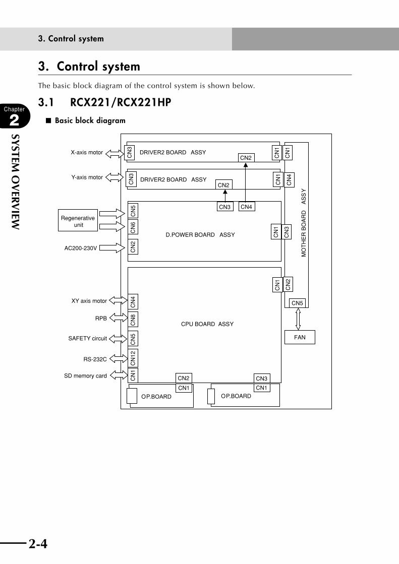
3. Control system
3. Control system The basic block diagram of the control system is shown below.
3.1 RCX221/RCX221HP■ Basic block diagram
D.POWER BOARD ASSY
CPU BOARD ASSY
DRIVER2 BOARD ASSY
DRIVER2 BOARD ASSY
FAN
OP.BOARD OP.BOARD
CN3 CN4
AC200-230V
Regenerative unit
X-axis motor
Y-axis motor
CN5
CN2
CN2
CN3CN2
XY axis motor
RPB
SAFETY circuit
RS-232C
SD memory card
CN1 CN1
CN
3C
N3
CN
5C
N2
CN
6C
N4
CN
8C
N5
CN
12C
N1
CN
1
CN
2C
N3
CN
1C
N1
CN
4
MO
TH
ER
BO
AR
D A
SS
Y
CN
1
CN
1
2-4 2-5
Chapter
2
SYSTEM
OV
ERVIEW
4. Optional devices
4. Optional devices
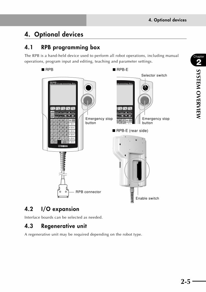
4.1 RPB programming box The RPB is a hand-held device used to perform all robot operations, including manual
operations, program input and editing, teaching and parameter settings.
Emergency stop button
Emergency stop button
RPB connector
Enable switch
Selector switch
■ RPB ■ RPB-E
■ RPB-E (rear side)
4.2 I/O expansionInterface boards can be selected as needed.
4.3 Regenerative unit A regenerative unit may be required depending on the robot type.
2-6
Chapter
2
SYSTEM
OV
ERVIEW
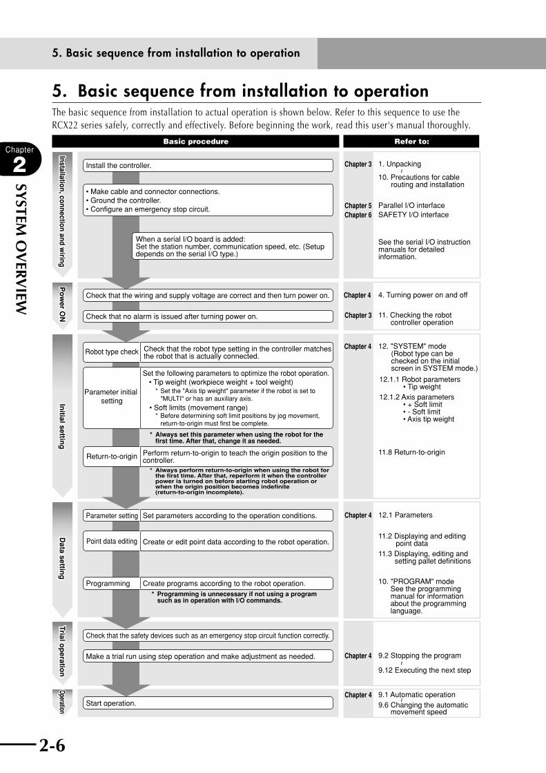
5. Basic sequence from installation to operationThe basic sequence from installation to actual operation is shown below. Refer to this sequence to use the RCX22 series safely, correctly and effectively. Before beginning the work, read this user's manual thoroughly.
Install the controller.
• Make cable and connector connections.• Ground the controller.• Configure an emergency stop circuit.
Start operation.
Check that the safety devices such as an emergency stop circuit function correctly.
Make a trial run using step operation and make adjustment as needed.
Check that the wiring and supply voltage are correct and then turn power on.
Check that no alarm is issued after turning power on.
Robot type check
Return-to-origin Perform return-to-origin to teach the origin position to the controller.
Parameter setting Set parameters according to the operation conditions.
Programming Create programs according to the robot operation.
Point data editing Create or edit point data according to the robot operation.
Parameter initial setting
Set the following parameters to optimize the robot operation. • Tip weight (workpiece weight + tool weight)
* Set the "Axis tip weight" parameter if the robot is set to "MULTI" or has an auxiliary axis.
* Before determining soft limit positions by jog movement, return-to-origin must first be complete.
* Always set this parameter when using the robot for the first time. After that, change it as needed.
* Always perform return-to-origin when using the robot for the first time. After that, reperform it when the controller power is turned on before starting robot operation or when the origin position becomes indefinite (return-to-origin incomplete).
* Programming is unnecessary if not using a program such as in operation with I/O commands.
Basic procedure Refer to:
4. Turning power on and off
11. Checking the robot controller operation
12. "SYSTEM" mode (Robot type can be checked on the initial screen in SYSTEM mode.)
12.1 Parameters
9.1 Automatic operation9.6 Changing the automatic movement speed
10. "PROGRAM" mode See the programming manual for information about the programming language.
11.2 Displaying and editing point data 11.3 Displaying, editing and setting pallet definitions
11.8 Return-to-origin
12.1.1 Robot parameters • Tip weight12.1.2 Axis parameters • + Soft limit • - Soft limit • Axis tip weight
9.2 Stopping the program
9.12 Executing the next step
Installation, connection and wiring
Po
wer O
NIn
itial setting
Data settin
gTrial o
peratio
nOperation
Installation, connection and wiring
Po
wer O
NIn
itial setting
Data settin
gTrial o
peratio
nOperation
See the serial I/O instruction manuals for detailed information.
1. Unpacking
10. Precautions for cable routing and installation
Parallel I/O interfaceSAFETY I/O interface
Chapter 3
Chapter 5Chapter 6
Chapter 4
Chapter 3
Chapter 4
Chapter 4
Chapter 4
Chapter 4
~~
~
• Soft limits (movement range)
When a serial I/O board is added:Set the station number, communication speed, etc. (Setup depends on the serial I/O type.)
Check that the robot type setting in the controller matches the robot that is actually connected.
5. Basic sequence from installation to operation

Chapter 3 INSTALLATION
Contents
1. Unpacking 3-11.1 Packing box 3-1
1.2 Unpacking 3-1
2. Installing the robot controller 3-22.1 Installation conditions 3-2
2.2 Installation methods 3-4
3. Connector names 3-6
4. Connecting to the power 3-74.1 Connection example 3-7
4.2 Power supply and ground terminals 3-8
4.3 AC power connector wiring 3-9
4.4 Considering power capacity and generated heat amount 3-10
4.5 Installing an external leakage breaker 3-11
4.6 Installing a circuit protector 3-12
4.7 Installing an electromagnetic contactor 3-12
4.8 Installing a noise filter 3-13
4.9 Installing a surge absorber 3-14
5. Connecting the robot cables 3-15
6. Connecting the RPB programming box 3-16
7. I/O connections 3-17
8. Connecting a host computer 3-18
9. Connecting a regenerative unit 3-19
10. Precautions for cable routing and installation 3-2110.1 Wiring methods 3-21
10.2 Precautions for installation 3-23
10.3 Methods of preventing malfunctions 3-23
11. Checking the robot controller operation 3-2411.1 Cable connection 3-24
11.2 Operation check 3-25

3-1
3-1
Chapter
3
INSTA
LLATIO
N
1. Unpacking
1. Unpacking
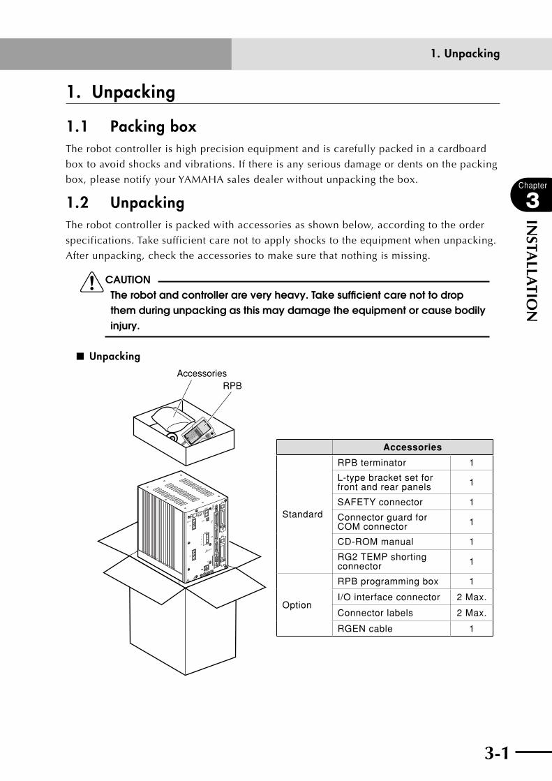
1.1 Packing box The robot controller is high precision equipment and is carefully packed in a cardboard
box to avoid shocks and vibrations. If there is any serious damage or dents on the packing
box, please notify your YAMAHA sales dealer without unpacking the box.
1.2 Unpacking The robot controller is packed with accessories as shown below, according to the order
specifications. Take sufficient care not to apply shocks to the equipment when unpacking.
After unpacking, check the accessories to make sure that nothing is missing.
cCAUTION The robot and controller are very heavy. Take sufficient care not to drop them during unpacking as this may damage the equipment or cause bodily injury.
■ Unpacking
RCX221
RPBAccessories
XM
YM
MOTOR
RGEN
TEMP
ACIN
N
L
L1
N1
SAFETY
SRVERR
RPB
ROBI/O
SD/COM
RDY
E-STOP
OP.1
OP.2
!
Accessories
Standard
RPB terminator 1
L-type bracket set for front and rear panels 1
SAFETY connector 1
Connector guard for COM connector 1
CD-ROM manual 1
RG2 TEMP shorting connector 1
Option
RPB programming box 1
I/O interface connector 2 Max.
Connector labels 2 Max.
RGEN cable 1

3-2
Chapter
3
INSTA
LLATIO
N
3-3
2. Installing the robot controller
2. Installing the robot controllerWhen installing, choose a proper place for your robot controller, taking into account your
system layout, accessibility for maintenance, etc.
2.1 Installation conditions
cCAUTION (1) When carrying the robot controller, use a dolly or similar hand truck and
move it carefully to avoid dropping and resultant damage. (2) Take care not to allow the connectors on the front of the robot controller
to be hit or bumped. Shocks received by the connectors may damage the PC boards in the controller.
(3) Be sure to give the cables used to connect the controller enough extra length to avoid strain and pulling at the connectors.
(4) Install the controller inside the control panel.(5) keep the controller away from oil and water. If the controller is to be
used under such adverse conditions, put it in a watertight box equipped with a cooling device.
(6) Install the controller on a flat, level surface. Do not stand the controller on its side or end, and do not install in an inverted position. Do not install in locations subject to excessive vibrations.
(7) Do not install the controller in locations where the ambient temperature may rise higher than the rated temperature.
(8) Do not block the fan vents on the bottom. If blocked, temperature inside the controller will rise leading to malfunctions, breakdowns or deterioration of electric components. Always provide a clearance of at least 17mm from the bottom panel so that the fan works properly.
3-2 3-3
Chapter
3
INSTA
LLATIO
N
2. Installing the robot controller
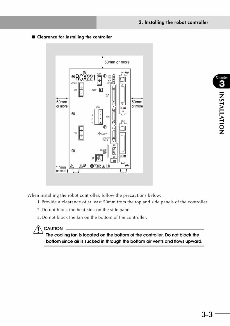
■ Clearance for installing the controller
XM
YM
MOTOR
RGEN
TEMP
ACIN
N
L
L1
N1
SAFETY
RPB
ROBI/O
SD/COM
E-STOP
PIN11-12EXT.E-STOP
OP.1
OP.2
!
RCX221 SRVERRRDY
50mm or more
50mm or more
17mmor more
50mm or more
When installing the robot controller, follow the precautions below.
1. Provide a clearance of at least 50mm from the top and side panels of the controller.
2. Do not block the heat-sink on the side panel.
3. Do not block the fan on the bottom of the controller.
cCAUTIONThe cooling fan is located on the bottom of the controller. Do not block the bottom since air is sucked in through the bottom air vents and flows upward.

3-4
Chapter
3
INSTA
LLATIO
N
3-5
2. Installing the robot controller
2.2 Installation methods There are three methods for installing the robot controller as explained below.
1) Using the rubber feet (attached as standard parts)
■ Using the rubber feet
RCX221
XM
YM
MOTOR
RGEN
TEMP
ACIN
N
L
L1
N1
SAFETY
SRV
ERR
RPB
ROBI/O
SD/COM
RDY
E-STOP
EXT.E-STOP
PIN11-12
OP.1
OP.2
!
2) Attaching the L-type brackets (supplied as standard accessories) to the front
■ Attaching the L-type brackets to the front
RCX221
XM
YM
MOTOR
RGEN
TEMP
ACIN
N
L
L1
N1
SAFETY
SRV
ERR
RPB
ROBI/O
SD/COM
RDY
E-STOP
EXT.E-STOP
PIN11-12
OP.1
OP.2
!
3-4 3-5
Chapter
3
INSTA
LLATIO
N
2. Installing the robot controller
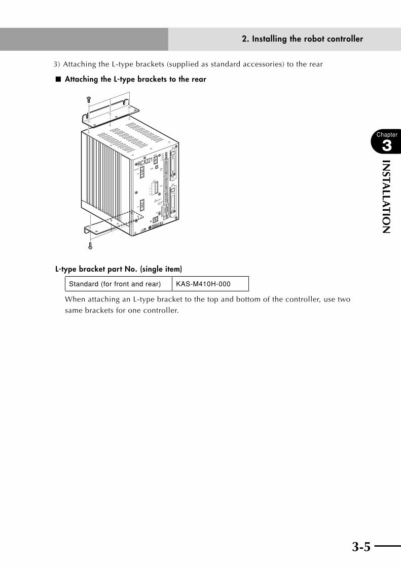
3) Attaching the L-type brackets (supplied as standard accessories) to the rear
■ Attaching the L-type brackets to the rear
RCX221
XM
YM
MOTOR
RGEN
TEMP
ACIN
N
L
L1
N1
SAFETY
SRV
ERR
RPB
ROBI/O
SD/COM
RDY
E-STOP
EXT.E-STOP
PIN11-12
OP.1
OP.2
!
L-type bracket part No. (single item)
Standard (for front and rear) KAS-M410H-000
When attaching an L-type bracket to the top and bottom of the controller, use two
same brackets for one controller.
3-6
Chapter
3
INSTA
LLATIO
N
3-7
3. Connector names
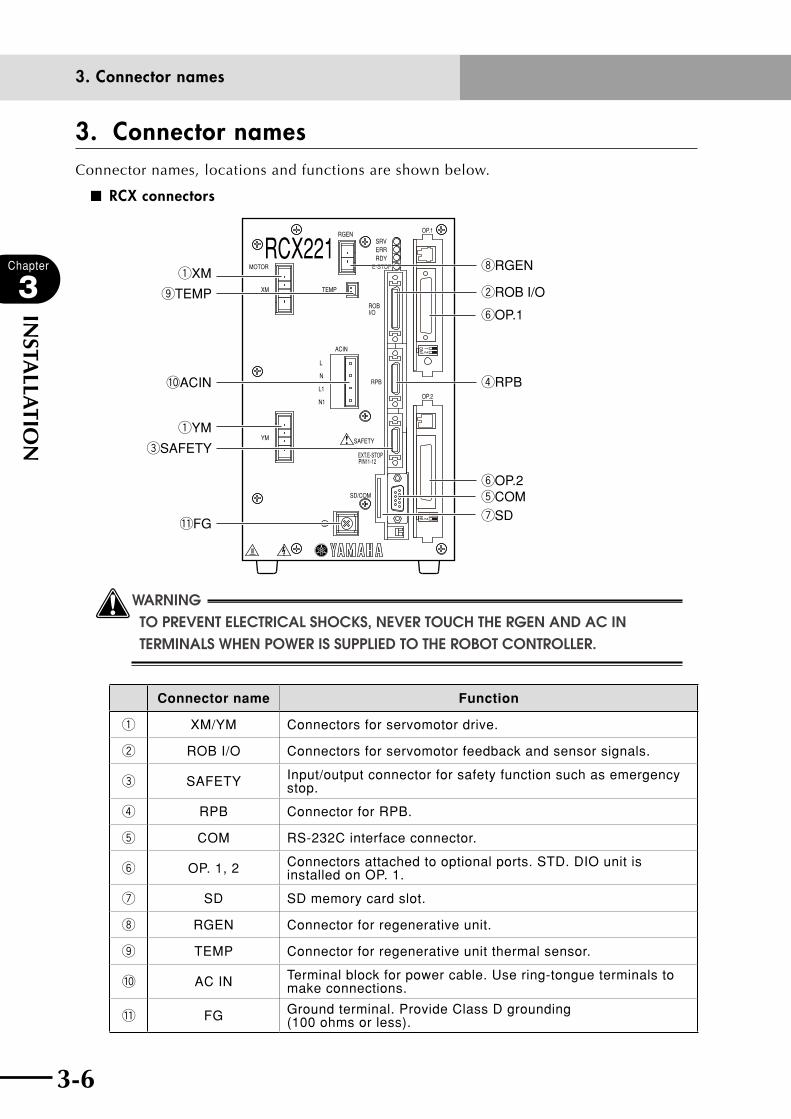
3. Connector namesConnector names, locations and functions are shown below.
■ RCX connectors
RCX221XM
YM
MOTOR
RGEN
TEMP
ACIN
N
L
L1
N1
SAFETY
RPB
ROBI/O
SD/COM
E-STOP
PIN11-12EXT.E-STOP
OP.1
OP.2
!
SRVERRRDY
tCOM
rRPB
eSAFETY
qXM
qYM
yOP.1
yOP.2
!0ACIN
oTEMP wROB I/O
!1FG
iRGEN
uSD
wWARNING TO PREVENT ELECTRICAL SHOCkS, NEVER TOUCH THE RGEN AND AC IN TERMINALS WHEN POWER IS SUPPLIED TO THE ROBOT CONTROLLER.
Connector name Function
q XM/YM Connectors for servomotor drive.
w ROB I/O Connectors for servomotor feedback and sensor signals.
e SAFETY Input/output connector for safety function such as emergency stop.
r RPB Connector for RPB.
t COM RS-232C interface connector.
y OP. 1, 2 Connectors attached to optional ports. STD. DIO unit is installed on OP. 1.
u SD SD memory card slot.
i RGEN Connector for regenerative unit.
o TEMP Connector for regenerative unit thermal sensor.
!0 AC IN Terminal block for power cable. Use ring-tongue terminals to make connections.
!1 FG Ground terminal. Provide Class D grounding (100 ohms or less).
3-6 3-7
Chapter
3
INSTA
LLATIO
N
4. Connecting to the power
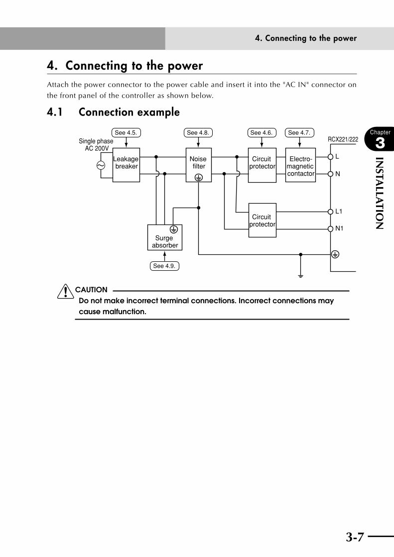
4. Connecting to the powerAttach the power connector to the power cable and insert it into the "AC IN" connector on
the front panel of the controller as shown below.
4.1 Connection example
L
N
L1
N1
Leakage breaker
Noise filter
Circuit protector
Circuit protector
Surge absorber
Electro-magnetic contactor
RCX221/222Single phase AC 200V
See 4.6.See 4.5. See 4.8. See 4.7.
See 4.9.
cCAUTION Do not make incorrect terminal connections. Incorrect connections may cause malfunction.

3-8
Chapter
3
INSTA
LLATIO
N
3-9
4. Connecting to the power
4.2 Power supply and ground terminals
wWARNING • topreventelectricAlsHocksorMAlfunctionscAusedbYnoise,
THE GROUND TERMINAL (PROTECTIVE CONDUCTOR) MUST BE GROUNDED PROPERLY.
• topreventelectricAlsHocks,nevertoucHtHeAcinterMinAlsWHEN POWER IS SUPPLIED TO THE ROBOT CONTROLLER.
cCAUTION Before connecting the power cable, be sure to check that the power supply voltage matches the power specifications of your controller.
Symbol Wiring Remarks
L 200 to 230V Live Main power supply (for motor power)
Wire cross-section 2.0 sq mm or moreN 200 to 230V Neutral
L1 200 to 230V LivePower for control Wire cross-section
1.25 sq mm or moreN1 200 to 230V Neutral
Ground Class D grounding (100 ohms or less) Tightening torque 1.4 Nm
■ Power terminal (200V to 230V specifications) and ground terminal
YM
ACIN
N
L
L1
N1
SAFETY
RPB
SD/COM
PIN11-12EXT.E-STOP
OP.2
!
Power terminal
Ground terminal
3-8 3-9
Chapter
3
INSTA
LLATIO
N
4. Connecting to the power
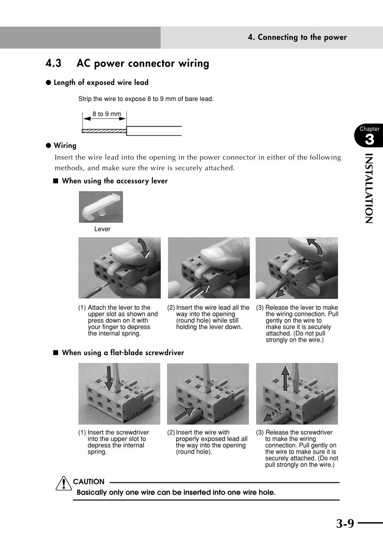
4.3 AC power connector wiring
l Length of exposed wire lead
Strip the wire to expose 8 to 9 mm of bare lead.
8 to 9 mm
l Wiring
Insert the wire lead into the opening in the power connector in either of the following
methods, and make sure the wire is securely attached.
■ When using the accessory lever
(1) Attach the lever to the upper slot as shown and press down on it with your finger to depress the internal spring.
(2) Insert the wire lead all the way into the opening (round hole) while still holding the lever down.
(3) Release the lever to make the wiring connection. Pull gently on the wire to make sure it is securely attached. (Do not pull strongly on the wire.)
Lever
■ When using a flat-blade screwdriver
(1) Insert the screwdriver into the upper slot to depress the internal spring.
(2) Insert the wire with properly exposed lead all the way into the opening (round hole).
(3) Release the screwdriver to make the wiring connection. Pull gently on the wire to make sure it is securely attached. (Do not pull strongly on the wire.)
cCAUTIONBasically only one wire can be inserted into one wire hole.

3-10
Chapter
3
INSTA
LLATIO
N
3-11
4. Connecting to the power
4.4 Considering power capacity and generated heat amountThe required power capacity and generated heat amount depend on the robot model and
the number of axes to be controlled.
cCAUTION The power supply voltage for the robot controller must always be regulated within ±10%. If the voltage drops, the robot controller may issue an abnormal voltage alarm causing the robot to trigger emergency stop. In contrast, operation at a voltage higher than specified may damage the robot controller or trigger emergency stop due to detecting an excessive motor power supply voltage.
Use the following tables as a guide to prepare a power supply and to determine the
control panel size, controller installation method, and cooling means.
■ When connected to 2 axes (Cartesian robot or multi-axis robot)
Axis current sensor valuePower capacity (VA) Generated heat
amount (W)X-axis Y-axis
05 05 500 53
10 05 700 58
20 05 1500 78
10 10 900 63
20 10 1700 83
20 202000 90
2400 (HP) 100
* Axis current sensor values can be substituted for each other.

3-10 3-11
Chapter
3
INSTA
LLATIO
N
4. Connecting to the power
4.5 Installing an external leakage breaker To ensure safety, a leakage breaker must be installed in the power supply connection
section of the robot controller.
Since the robot controller drives the motors by PWM control of IGBT, leakage current
flows at high frequencies. This might cause the external leakage breaker to malfunction.
When installing an external leakage current breaker, it is important to choose the optimum
sensitivity current rating (IΔn).
(Check the leakage breaker manufacturer's data sheets to select the optimum product
compatible with inverters.)
wWARNINGELECTRICAL SHOCkS, INjURIES OR FIRES MIGHT OCCUR IF THE MOTOR BREAkS DOWN WHILE THE ROBOT CONTROLLER IS USED WITHOUT INSTALLING A LEAkAGE BREAkER.
cCAUTION 1. Leak current was measured with a leak tester with a low-pass filter turned
on (100Hz). •leaktester:Hiokielectric3283
2. When using two or more controllers, sum the leakage current of each controller.
3. Make sure that the controller is securely grounded. 4. Stray capacitance between the cable and FG may vary depending on
the cable installation condition, causing the leakage current to fluctuate.
Leakage current
RCX221 control power supply (L1, N1)1mA in total
RCX221 main power supply (L, N)

3-12
Chapter
3
INSTA
LLATIO
N
3-13
4. Connecting to the power
4.6 Installing a circuit protectorTo ensure safety, a circuit protector must be installed in the power supply connection
section of the robot controller.
An inrush current, which might be from several to more than 10 times higher than the
rated current, flows at the instant the controller is turned on or the robot motors start to
operate. When installing an external circuit protector for the robot controller, select a
circuit protector that provides optimum operating characteristics.
To ensure proper operation, we recommend using a medium to slow response circuit
protector with an inertial delay function. (Refer to the circuit protector manufacturer's
data sheets for making the selection.)
wWARNINGELECTRICAL SHOCkS, INjURIES OR FIRES MIGHT OCCUR IF THE MOTOR BREAkS DOWN WHILE THE ROBOT CONTROLLER IS USED WITHOUT INSTALLING A CIRCUIT PROTECTOR.
Rated current Operating characteristics
RCX221 control power supply (L1, N1) 3ASlow type with inertial delay
RCX221 main power supply (L, N) 10A
4.7 Installing an electromagnetic contactorWhen controlling the power on/off operation of the robot controller using an external unit
such as a PLC, an electromagnetic contactor should be installed on the AC power supply
line for the controller. Select an electromagnetic contactor that falls under the required
safety category and control the open/close operation using a circuit that meets the safety
category. In this case, separate the main power supply line from the control power supply
line, and install the electromagnetic contactor on the main power supply side.
To control the operation using emergency stop, turn the main power on and off.

3-12 3-13
Chapter
3
INSTA
LLATIO
N
4. Connecting to the power
4.8 Installing a noise filterTo comply with CE marking requirements, use a noise filter to suppress the noise on the
power supply line.
■ Dimensional outlines of recommended noise filterManufacturer : TDK-Lambda Corporation
Type No. : MBS-1215-22
LC
unit: mm
LC
φ4.88-
5-M4
(Mounting holes)
C LNAME PLATE
105±0.5
18±0
.5
45±0
.5
65±
1
36
12
27
40±122MAX 95±1 22MAX
115±1
2 4
1 3
Case: Iron

3-14
Chapter
3
INSTA
LLATIO
N
3-15
4. Connecting to the power
4.9 Installing a surge absorberThe controller contains a protection circuit to protect the internal components from surge
noise that may be generated by lightning. To further enhance the surge immunity, install
an external surge absorber.
■ Dimensional outlines of recommended surge absorberManufacturer : SOSHIN ELECTRIC CO., LTD.
Type No. : LT-C12G801WS
Status indicator
φ4.3
+0.3
-0.1
25 ±1
.04
33.5
±1.0
19 ±1.0
Wire (line)(Black)
Wire (earth)(Green/Yellow)
38 ±1.022.5
±1.0
250
+25
-028
±1.0
4 ±0
.5Green : NormalRed : Abnormal

3-14 3-15
Chapter
3
INSTA
LLATIO
N
5. Connecting the robot cables
5. Connecting the robot cablesConnect the robot cables to the "XM", "YM" and "ROB I/O" connectors on the front panel
of the controller as shown below.
The robot cable specifications depend on the robot model, so refer to the robot user's
manual for details.
n NOTE
Check robot cables for bent pins, kinks, and other damage before
connecting.
wWARNING • tHepowertotHecontrollerMustbeoffwHenconnectingtHe
ROBOT CABLES. • keeprobotcAblessepArAtefroMtHerobotcontrollerpower
CONNECTION LINES AND OTHER EqUIPMENT POWER LINES. USING THEM IN CLOSE CONTACT WITH LINES CARRYING POWER MAY CAUSE MALFUNCTIONS.
cCAUTION Always securely connect the robot cables. If they are not securely connected and fail to make good contact, the robot may malfunction. Before turning on the controller, make sure again that the cables are securely connected. Also make sure that the robot is properly grounded. For details on the grounding method, refer to the robot user's manual.
■ Robot cable connection
RCX221
XM
YM
MOTOR
RGEN
TEMP
ACIN
N
L
L1
N1
SAFETY
SRV
ERR
RPB
ROBI/O
SD/COM
RDY
E-STOP
EXT.E-STOP
PIN11-12
OP.1
OP.2
!
Connected to YAMAHA robot

3-16
Chapter
3
INSTA
LLATIO
N
3-17
6. Connecting the RPB programming box
6. Connecting the RPB programming boxAs shown in the figure below, the RPB should be connected to the RPB connector on the front panel of the robot controller. If not connecting the RPB, plug a terminator (supplied as an accessory) into the RPB connector.
cCAUTION Use caution since the RPB connector must be connected in the correct direction. Connecting in the wrong direction may cause malfunctions or breakdowns.
■ RPB programming box connection
RCX221
XM
YM
MOTOR
RGEN
TEMP
ACIN
N
L
L1
N1
SAFETY
SRVERR
RPB
ROBI/O
SD/COM
RDY
E-STOP
EXT.E-STOP
PIN11-12
OP.1
OP.2
!
RPB programming box
l Connecting a terminator
If not connecting the RPB, plug the terminator (supplied) into the RPB connector.
■ Connecting a terminator
RCX221XM
YM
MOTOR
RGEN
TEMP
ACIN
N
L
L1
N1
SAFETY
RPB
ROBI/O
SD/COM
E-STOP
PIN11-12EXT.E-STOP
OP.1
OP.2
!
SRVERRRDY
RCX221
XM
YM
MOTOR
RGEN
TEMP
ACIN
N
L
L1
N1
SAFETY
SRV
ERR
RPB
ROBI/O
SD/COM
RDY
E-STOP
EXT.E-STOP
PIN11-12
OP.2
!
cCAUTION If not connecting the RPB, always be sure to plug the terminator (supplied) into the RPB connector.Emergency stop in the robot controller is triggered when the RPB is disconnected from the robot controller, because a B-contact (normally closed) type emergency stop button is provided on the RPB. Plug the RPB terminator into the RPB connector to avoid such an emergency stop.

3-16 3-17
Chapter
3
INSTA
LLATIO
N
7. I/O connections
7. I/O connectionsThe various input/output (I/O) signals from peripheral equipment can be connected to the
robot controller. Each I/O is set with a number, and the I/O connector to be used depends
on that number.
For more detailed information on inputs and outputs, see Chapter 5, "Parallel I/O interface"
or see Chapter 6, "SAFETY I/O interface".
The following describes terms used in the manual.
a. NPN specifications NPN specifications indicate that a DO (digital output) type NPN open-collector
transistor is used for the I/O port having a transistor and photocoupler, and a
corresponding DI (digital input) is also used. NPN specifications therefore make use
of a sink output and a source input (see drawing below).
■ Connection for NPN specifications
Current
CurrentDO output (sink type)
DI input (source type)
N.COM
P.COM
NPN
b. PNP specifications PNP specifications indicate that a DO (digital output) type NPN open emitter
transistor is used for the I/O port having a transistor and photocoupler, and a
corresponding DI (digital input) is also used. PNP specifications therefore make use
of a source output and a sink input (see drawing below).
■ Connection for PNP specifications
DO output (source type)
DI input (sink type)
Current
Current
N.COM
P.COM
PNP

3-18
Chapter
3
INSTA
LLATIO
N
3-19
8. Connecting a host computer
8. Connecting a host computerAs a standard feature, the robot controller has an RS-232C interface port for data
communication with a host computer. Most computer models having an RS-232C port can
be interfaced to the robot controller, by connecting the COM connector on the front of
the robot controller to the RS-232C port of the computer using a communication cable.
For more detailed information on the RS-232C interface, see "RS-232C Interface" in
Chapter 7.
n NOTE
D-SUB 9P (female) connector is for RS-232C interface.
■ Host computer connection
RCX221XM
YM
MOTOR
RGEN
TEMP
ACIN
N
L
L1
N1
SAFETY
RPB
ROBI/O
SD/COM
E-STOP
PIN11-12EXT.E-STOP
OP.1
OP.2
!
SRVERRRDY
COM connector
Host computer
25 pins 25 pinsor
9 pins
9 pins 9 pins
9 pins
COM port
Straight serial conversion adapter (option)
Communication cable (option)

3-18 3-19
Chapter
3
INSTA
LLATIO
N
9. Connecting a regenerative unit
9. Connecting a regenerative unitWhen a regenerative unit is required, connect it to the RGEN and TEMP connectors on
the front panel of the controller. The regenerative unit is attached to the right side of the
controller prior to shipping.
n NOTE
• TheRCX221mayrequirearegenerativeunitdependingontherobot
type to be connected.
• Checkthecableandconnectorsforbentpins,kinks,andotherdamage
before connecting.
wWARNING • tHepowertotHecontrollerMustbeoffwHenconnectingtHe
REGENERATIVE UNIT TO THE CONTROLLER.• topreventelectricAlsHocks,nevertoucHtHergenconnector
WHEN POWER IS SUPPLIED TO THE CONTROLLER.
cCAUTION Always securely connect the cable. Poor connections or contact failure may cause malfunctions.
■ Generative unit connection
XM
YM
MOTOR
RGEN
TEMP
ACIN
N
L
L1
N1
SD/COM
OP.1
OP.2
!
RCX221
SAFETY
RPB
ROBI/O
E-STOP
PIN11-12EXT.E-STOP
SRVERRRDY
Regenerative unit
Supplied cables
RGEN connector
TEMP connector
RG2
TEMP
RGEN
3-20
Chapter
3
INSTA
LLATIO
N
3-21
9. Connecting a regenerative unit
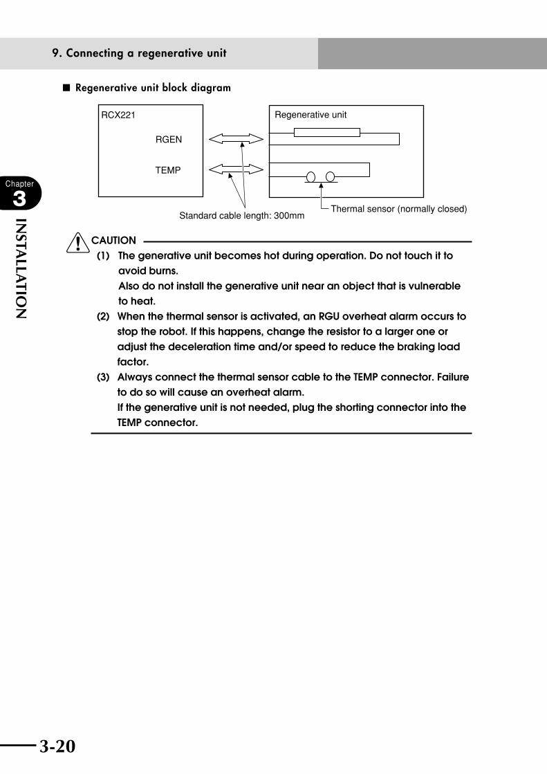
■ Regenerative unit block diagram
RCX221
RGEN
TEMP
Regenerative unit
Standard cable length: 300mmThermal sensor (normally closed)
cCAUTION(1) The generative unit becomes hot during operation. Do not touch it to
avoid burns. Also do not install the generative unit near an object that is vulnerable to heat.
(2) When the thermal sensor is activated, an RGU overheat alarm occurs to stop the robot. If this happens, change the resistor to a larger one or adjust the deceleration time and/or speed to reduce the braking load factor.
(3) Always connect the thermal sensor cable to the TEMP connector. Failure to do so will cause an overheat alarm. If the generative unit is not needed, plug the shorting connector into the TEMP connector.
3-20 3-21
Chapter
3
INSTA
LLATIO
N
10. Precautions for cable routing and installation
10. Precautions for cable routing and installation
10.1 Wiring methods Various cables are used to connect the robot controller to peripheral devices. Follow the
precautions below when making cable routing and connections to avoid malfunctions due
to noise.
cCAUTION As a general guide keep the specified cables separated at least 100mm from each other.
1) Keep the DIO cables, SAFETY cable, robot cables and power cable separate from each
other. Never bundle them together.
2) Keep the communication cable, robot cables and power cable separate from each
other. Never bundle them together.
3) Keep robot cables separate from the power cable. Never bundle them together.
4) Keep robot cables away from other equipment power lines. Never bundle them
together.
5) The wiring of electromagnetic contactors, induction motors, solenoid valves or brake
solenoids should be separate from the DIO cable, communication cable, SAFETY
cable and robot cable. Never pass them through the same conduit or bundle them
together.

3-22
Chapter
3
INSTA
LLATIO
N
3-23
10. Precautions for cable routing and installation
Refer to the drawing below when making the cable connections.
■ Cable connection
RCX221XM
YM
MOTOR
RGEN
TEMP
ACIN
N
L
L1
N1
SAFETY
RPB
ROBI/O
SD/COM
E-STOP
PIN11-12EXT.E-STOP
OP.1
OP.2
!
SRVERRRDY
DIO cable
SAFETY cable
Pow
er cable
Robot cable
Com
munication cable

3-22 3-23
Chapter
3
INSTA
LLATIO
N
10. Precautions for cable routing and installation
10.2 Precautions for installation This robot controller is not designed with an explosion-proof, dust-proof or drip-proof
structure. Do not install it in the following locations or environments
(1) where exposed to flammable gases or liquids.
(2) where conductive debris such as metal cutting chips are spread.
(3) where exposed to corrosive gases such as acid gases and alkaline gases.
(4) where exposed to cutting oil, grinding fluids and machining mist.
(5) near sources of electrical noise, such as large inverters, high-power high-frequency
generators, large switching devices, and welding machines.
10.3 Methods of preventing malfunctions To prevent malfunctions due to noise, take into account the following points.
1) Place a noise filter and ferrite core at a point near the robot controller.
Do not bundle the primary wiring and secondary wiring of the noise filter together.
■ Bad example
Noise filter
Robotcontroller
Primary wiring
Secondary wiring L1
N1
LN
Ground wire
•Primarywiringandsecondarywiringofthenoisefilterarebundledtogether.
•Groundwireisbundledwithprimarywiringofthenoisefilter.
2) Always attach a surge absorber to the coil of inductive loads (inductive motor,
solenoid valve, brake solenoid and relay) located near the robot controller.
Example of surge absorber
■ For inductive motor
A: Surge killer (Okaya Electric Industries CRE-50500, 3CRE-50500 or equivalent)
Single-phasemotor
A 3-phasemotor
A
■ For solenoid valve, solenoid
B: Diode, varistor, CR elementsDC type
C: Varistor, CR elementsAC type
B C

3-24
Chapter
3
INSTA
LLATIO
N
3-25
11. Checking the robot controller operation
11. Checking the robot controller operationThis section explains how to check the controller operation using a special connector that
comes with the controller and an applicable robot. Before beginning this check, finish
making connections to the following items.
• Powersupply(Donotsupplypoweruntilyouactuallybegintheoperationcheck.)
• Robotcable
• RPBprogrammingbox
• Regenerativeunit(ifneeded)
• SAFETYconnector(supplied)
(Pins 1 and 10 are shorted, pins 2, 3, 11 and 14 are shorted, and pins 12 and 13 are
shorted in the SAFETY connector.)
The connection status of emergency stop input signal is described in detail in Chapter
6, "SAFETY I/O interface".
11.1 Cable connection ■ Cable connection
RCX221
XM
YM
MOTOR
RGEN
TEMP
ACIN
N
L
L1
N1
SAFETY
SRV
ERR
RPB
ROBI/O
SD/COM
RDY
E-STOP
EXT.E-STOP
PIN11-12
OP.1
OP.2
!
YAMAHA robot
RPB
SAFETY connector (supplied)
3-24 3-25
Chapter
3
INSTA
LLATIO
N
11. Checking the robot controller operation
11.2 Operation check After connecting the robot and special connector (supplied) to the controller, turn on the
power to the controller and check the following points.
Normal operation
•The"RDY"and"SRV"LEDlampsonthefrontpanelofthecontrollerlightup.The
"ERR" LED lamp is off.
•Whenthe"SAFE"modesettingisenabledandtheserialI/Oisconnected,the"SRV"
LED lamp does not light up.
Abnormal operation
•The"RDY"and"ERR"LEDlampsonthefrontpanelofthecontrollerlightup.
However, the "RDY" LED flashes if a serious error has occurred.
•ChecktheerrormessagedisplayedontheRPBandtakecorrectiveactionaccording
to the description given in Chapter 9, "Troubleshooting".

3-26
MEMO
Chapter 4 OPERATION
Contents
1. Operation overview 4-1
2. The RCX robot controller 4-22.1 Part names 4-2
2.2 Main functions 4-2
3. RPB programming box 4-33.1 Part names 4-3
3.2 Main functions 4-3
3.3 Connection to the robot controller 4-4
3.4 Changing the RPB screen settings 4-5
4. Turning power on and off 4-6
5. Operation keys 4-85.1 RPB screen 4-8
5.2 Operation key layout 4-9
5.3 Basic key operation 4-10
5.4 Function keys 4-11
5.5 Control keys 4-13
5.6 Data keys 4-15
5.7 Other keys 4-15
6. Emergency stop 4-166.1 Emergency stop reset 4-17
7. Mode configuration 4-197.1 Basic operation modes 4-19
7.2 Other operation modes 4-20
7.3 Mode hierarchy 4-21
8. "SERVICE" mode 4-268.1 Operation device 4-26
8.2 Prohibition of "AUTO" mode operation 4-26
8.3 Hold-to-Run function 4-26
8.4 Limitations on robot operating speed 4-27

9. "AUTO" mode 4-289.1 Automatic operation 4-31
9.2 Stopping the program 4-32
9.3 Resetting the program 4-33
9.4 Switching task display 4-35
9.5 Switching the program 4-36
9.6 Changing the automatic movement speed 4-37
9.7 Executing the point trace 4-389.7.1 PTP motion mode 4-40
9.7.2 ARCH motion mode 4-41
9.7.3 Linear interpolation motion mode 4-43
9.8 Direct command execution 4-44
9.9 Break point 4-459.9.1 Setting break points 4-46
9.9.2 Deleting break points 4-47
9.10 Executing a step 4-48
9.11 Skipping a step 4-48
9.12 Executing the next step 4-49
10. "PROGRAM" mode 4-5010.1 Scrolling a program listing 4-51
10.2 Program editing 4-5210.2.1 Cursor movement 4-54
10.2.2 Insert/Overwrite mode switching 4-55
10.2.3 Inserting a line 4-56
10.2.4 Deleting a character 4-56
10.2.5 Deleting a line 4-56
10.2.6 User function key display 4-57
10.2.7 Quitting program editing 4-58
10.2.8 Specifying the copy/cut lines 4-58
10.2.9 Copying the selected lines 4-59
10.2.10 Cutting the selected lines 4-59
10.2.11 Pasting the data 4-60
10.2.12 Backspace 4-60
10.2.13 Line jump 4-61
10.2.14 Searching a character string 4-62
10.3 Directory 4-6310.3.1 Cursor movement 4-65
10.3.2 Registering a new program name 4-65
10.3.3 Directory information display 4-66

10.3.4 Copying a program 4-67
10.3.5 Erasing a program 4-68
10.3.6 Renaming a program 4-69
10.3.7 Changing the program attribute 4-70
10.3.8 Displaying object program information 4-71
10.3.9 Creating a sample program automatically 4-72
10.4 Compiling 4-74
10.5 Line jump and character string search 4-75
10.6 Registering user function keys 4-75
10.7 Resetting an error in the selected program 4-79
11. "MANUAL" mode 4-8011.1 Manual movement 4-82
11.2 Displaying and editing point data 4-8511.2.1 Point data input and editing 4-87
11.2.1.1 Restoring point data 4-88
11.2.2 Point data input by teaching 4-89
11.2.3 Point data input by direct teaching 4-91
11.2.4 Point jump display 4-92
11.2.5 Copying point data 4-93
11.2.6 Erasing point data 4-95
11.2.7 Point data trace 4-96
11.2.8 Point comment input and editing 4-96
11.2.8.1 Point comment input and editing 4-98
11.2.8.2 Point data input by teaching 4-98
11.2.8.3 Jump to a point comment 4-99
11.2.8.4 Copying a point comment 4-99
11.2.8.5 Erasing point comments 4-101
11.2.8.6 Point comment search 4-102
11.2.9 Point data error reset 4-103
11.3 Displaying, editing and setting pallet definitions 4-10411.3.1 Editing pallet definitions 4-106
11.3.1.1 Point setting in pallet definition 4-107
11.3.1.1.1 Editing the point in pallet definition 4-108
11.3.1.1.2 Setting the point in pallet definition by teaching 4-108
11.3.2 Pallet definition by teaching 4-109
11.3.3 Copying a pallet definition 4-112
11.3.4 Deleting a pallet definition 4-113
11.4 Changing the manual movement speed 4-114
11.5 Displaying, editing and setting shift coordinates 4-11511.5.1 Editing shift coordinates 4-117
11.5.1.1 Restoring shift coordinates 4-118
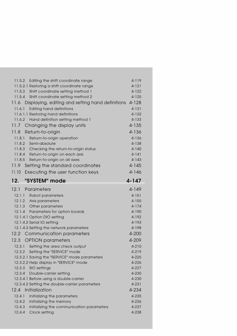
11.5.2 Editing the shift coordinate range 4-119
11.5.2.1 Restoring a shift coordinate range 4-121
11.5.3 Shift coordinate setting method 1 4-122
11.5.4 Shift coordinate setting method 2 4-125
11.6 Displaying, editing and setting hand definitions 4-12811.6.1 Editing hand definitions 4-131
11.6.1.1 Restoring hand definitions 4-132
11.6.2 Hand definition setting method 1 4-133
11.7 Changing the display units 4-135
11.8 Return-to-origin 4-13611.8.1 Return-to-origin operation 4-136
11.8.2 Semi-absolute 4-138
11.8.3 Checking the return-to-origin status 4-140
11.8.4 Return-to-origin on each axis 4-141
11.8.5 Return-to-origin on all axes 4-143
11.9 Setting the standard coordinates 4-145
11.10 Executing the user function keys 4-146
12. "SYSTEM" mode 4-14712.1 Parameters 4-149
12.1.1 Robot parameters 4-151
12.1.2 Axis parameters 4-155
12.1.3 Other parameters 4-174
12.1.4 Parameters for option boards 4-190
12.1.4.1 Option DIO setting 4-192
12.1.4.2 Serial IO setting 4-193
12.1.4.3 Setting the network parameters 4-198
12.2 Communication parameters 4-200
12.3 OPTION parameters 4-20912.3.1 Setting the area check output 4-210
12.3.2 Setting the "SERVICE" mode 4-219
12.3.2.1 Saving the "SERVICE" mode parameters 4-225
12.3.2.2 Help display in "SERVICE" mode 4-226
12.3.3 SIO settings 4-227
12.3.4 Double-carrier setting 4-230
12.3.4.1 Before using a double-carrier 4-230
12.3.4.2 Setting the double-carrier parameters 4-231
12.4 Initialization 4-23412.4.1 Initializing the parameters 4-235
12.4.2 Initializing the memory 4-236
12.4.3 Initializing the communication parameters 4-237
12.4.4 Clock setting 4-238

12.4.5 System generation 4-239
12.5 Self diagnosis 4-24012.5.1 Controller check 4-241
12.5.2 Error history display 4-242
12.5.3 Displaying the total operation time 4-243
12.5.4 System error details display 4-244
12.6 Backup processes 4-24512.6.1 SD memory card 4-246
12.6.1.1 Loading files 4-248
12.6.1.2 Saving files 4-250
12.6.1.3 Deleting files 4-252
12.6.1.4 Previewing files 4-253
12.6.2 Internal flash ROM 4-254
12.6.2.1 Loading files 4-255
12.6.2.2 Saving files 4-257
12.6.2.3 Initializing the files 4-258
13. "MONITOR" mode 4-259
14. "UTILITY" mode 4-26214.1 Canceling emergency stop; Motor power and servo on/off 4-264
14.1.1 Canceling emergency stop 4-264
14.1.2 Motor power and servo on/off 4-265
14.2 Enabling/disabling the sequence execution flag 4-267
14.3 Resetting the output ports 4-268
14.4 Changing the execution level 4-26914.4.1 Changing the execution level 4-270
14.4.2 Displaying the Help message 4-271
14.5 Changing the access level (operation level) 4-27214.5.1 Entering the password 4-273
14.5.2 Changing the access level 4-274
14.5.3 Displaying the Help message 4-275

4-1
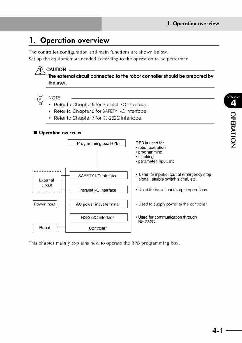
4-1
Chapter
4
OPER
ATIO
N
1. Operation overviewThe controller configuration and main functions are shown below.
Set up the equipment as needed according to the operation to be performed.
cCAUTIONThe external circuit connected to the robot controller should be prepared by the user.
n NOTE
• RefertoChapter5forParallelI/Ointerface.
• RefertoChapter6forSAFETYI/Ointerface.
• RefertoChapter7forRS-232Cinterface.
■ Operation overview
Parallel I/O interface
Robot
Power input
External circuit
AC power input terminal
Programming box RPB
SAFETY I/O interface
• Used to supply power to the controller.
RPB is used for • robot operation• programming• teaching• parameter input, etc.
• Used for basic input/output operations.
• Used for input/output of emergency stop signal, enable switch signal, etc.
• Used for communication through RS-232C.
RS-232C interface
Controller
This chapter mainly explains how to operate the RPB programming box.
1. Operation overview
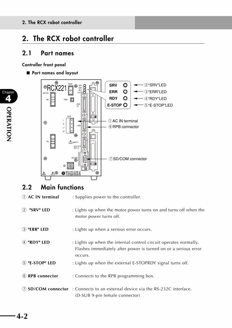
4-2
Chapter
4
OPER
ATIO
N
4-3
2. The RCX robot controller
2.1 Part names
Controller front panel
■ Part names and layout
RCX221XM
YM
MOTOR
RGEN
TEMP
ACIN
N
L
L1
N1
SAFETY
RPB
ROBI/O
SD/COM
E-STOP
PIN11-12EXT.E-STOP
OP.1
OP.2
!
SRVERRRDY
w“SRV”LED
e“ERR”LED
r“RDY”LED
t“E-STOP”LED
SRV
ERR
RDY
E-STOP
qAC IN terminal
yRPB connector
uSD/COM connector
2.2 Main functionsq AC IN terminal : Supplies power to the controller.
w "SRV" LED : Lights up when the motor power turns on and turns off when the
motor power turns off.
e "ERR" LED : Lights up when a serious error occurs.
r "RDY" LED : Lights up when the internal control circuit operates normally.
Flashes immediately after power is turned on or a serious error
occurs.
t "E-STOP" LED : Lights up when the external E-STOPRDY signal turns off.
y RPB connector : Connects to the RPB programming box.
u SD/COM connector : Connects to an external device via the RS-232C interface.
(D-SUB 9-pin female connector)
2. The RCX robot controller

4-2 4-3
Chapter
4
OPER
ATIO
N
3. RPB programming boxThe RPB programming box connects to the robot controller and is used to edit and execute
robot programs.
3.1 Part names■ Programming box
yEnable switch (RPB-E only)
Rear view
tSelector switch (RPB-E only)qDisplay (liquid crystal screen)
eEmergency stop button
wSheet key
rRPB connector
3.2 Main functionsq Display (liquid crystal screen)
This is a liquid crystal display (LCD) with 40 characters × 8 lines, showing various types of information. The screen contrast is adjustable.
w Sheet keys
Use these keys to operate the robot or edit programs. The sheet keys are grouped into three main types: function keys, control keys and data keys.
e Emergency stop button
Pressing this button during operation immediately stops robot operation. This is a B-contact (normally closed) type switch.
r RPB connector
Use this connector to connect the RPB programming box to the robot controller.
3. RPB programming box
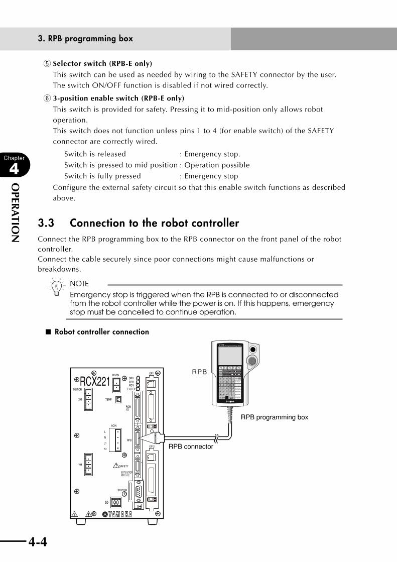
4-4
Chapter
4
OPER
ATIO
N
4-5
t Selector switch (RPB-E only)
This switch can be used as needed by wiring to the SAFETY connector by the user. The switch ON/OFF function is disabled if not wired correctly.
y 3-position enable switch (RPB-E only)
This switch is provided for safety. Pressing it to mid-position only allows robot operation. This switch does not function unless pins 1 to 4 (for enable switch) of the SAFETY connector are correctly wired.
Switch is released : Emergency stop.
Switch is pressed to mid position : Operation possible
Switch is fully pressed : Emergency stop
Configure the external safety circuit so that this enable switch functions as described above.
3.3 Connection to the robot controllerConnect the RPB programming box to the RPB connector on the front panel of the robot controller.Connect the cable securely since poor connections might cause malfunctions or breakdowns.
n NOTE
Emergency stop is triggered when the RPB is connected to or disconnected from the robot controller while the power is on. If this happens, emergency stop must be cancelled to continue operation.
■ Robot controller connection
RCX221XM
YM
MOTOR
RGEN
TEMP
ACIN
N
L
L1
N1
SAFETY
RPB
ROBI/O
SD/COM
E-STOP
PIN11-12EXT.E-STOP
OP.1
OP.2
!
SRVERRRDY
RPB
RPB programming box
RPB connector
3. RPB programming box
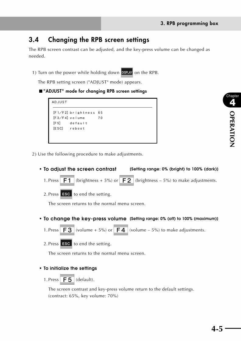
4-4 4-5
Chapter
4
OPER
ATIO
N
3.4 Changing the RPB screen settingsThe RPB screen contrast can be adjusted, and the key-press volume can be changed as
needed.
1) Turn on the power while holding down on the RPB.
The RPB setting screen ("ADJUST" mode) appears.
■ "ADJUST" mode for changing RPB screen settings
ADJUST
[F1/F2]brightness 65
[F3/F4]volume 70
[F5] default
[ESC] reboot
2) Use the following procedure to make adjustments.
•toadjustthescreencontrast [Setting range: 0% (bright) to 100% (dark)]
1. Press (brightness + 5%) or (brightness – 5%) to make adjustments.
2. Press to end the setting.
The screen returns to the normal menu screen.
•tochangethekey-pressvolume [Setting range: 0% (off) to 100% (maximum)]
1. Press (volume + 5%) or (volume – 5%) to make adjustments.
2. Press to end the setting.
The screen returns to the normal menu screen.
•To initialize the settings
1. Press (default).
The screen contrast and key-press volume return to the default settings.
(contract: 65%, key volume: 70%)
3. RPB programming box

4-6
Chapter
4
OPER
ATIO
N
4-7
4. Turning power on and offThis section explains how to turn power on and off, assuming that the external emergency
stop circuit and other necessary units are connected according to the instructions in
Chapter 3, "Installation", and also that the robot controller operates correctly.
1) Connect the RPB to the RPB connector on the front panel of the robot controller.
cCAUTIONWhen connecting the RPB to the robot controller, always use the dedicated cable and connector attached to the RPB. Do not modify this cable or extend it by using a relay unit, etc.
2) Supply the power to the AC IN terminal on the front panel of the robot controller.
The "PWR" LED lights up and the "MANUAL" mode screen appears. (After the "PWR"
LED is lit, it will take a maximum of three seconds for the controller to operate
normally.)
n NOTE
• Ifanerrormessage"Parameterdestroyed"or"Memorydestroyed"
appears on the screen when the robot controller is turned on, be sure to
initialize the parameters and memory in "SYSTEM" mode before
performing return-to-origin. Refer to '12. "SYSTEM" mode' in Chapter 4 for
detailed information.
• Iftheerrormessage"10.21:Sys.backupbatterylowvoltage"appears
while the power supply is turned on, replace the lithium battery (typically
4 years service life) in the robot controller.
n NOTE
• Afterturningofftherobotcontroller,waitatleast5secondsbefore
turning the power back on again. If power is turned on again too quickly
after the power was turned off, the controller might not start up correctly.
• Donotturnofftherobotcontrollerduringprogramexecution.Ifturned
off, this causes errors in the internal system data and the program may
not restart correctly when the power is again turned on. Always quit or
stop the program before turning off the robot controller.
3) When "SAFE" mode or serial I/O setting is enabled, the controller always starts with
the robot servo turned off. To turn on the robot servo, refer to '14. "UTILITY" mode' in
this chapter.
4. Turning power on and off
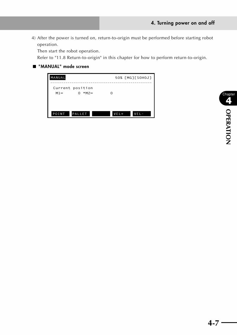
4-6 4-7
Chapter
4
OPER
ATIO
N
4) After the power is turned on, return-to-origin must be performed before starting robot
operation.
Then start the robot operation.
Refer to "11.8 Return-to-origin" in this chapter for how to perform return-to-origin.
■ "MANUAL" mode screen
MANUAL
–––––––––––––––––––––––––––––––––––––––––––––––––––––
Current position
M1= 0 *M2= 0
POINT PALLET VEL+ VEL-
50% [MG][S0H0J]
4. Turning power on and off
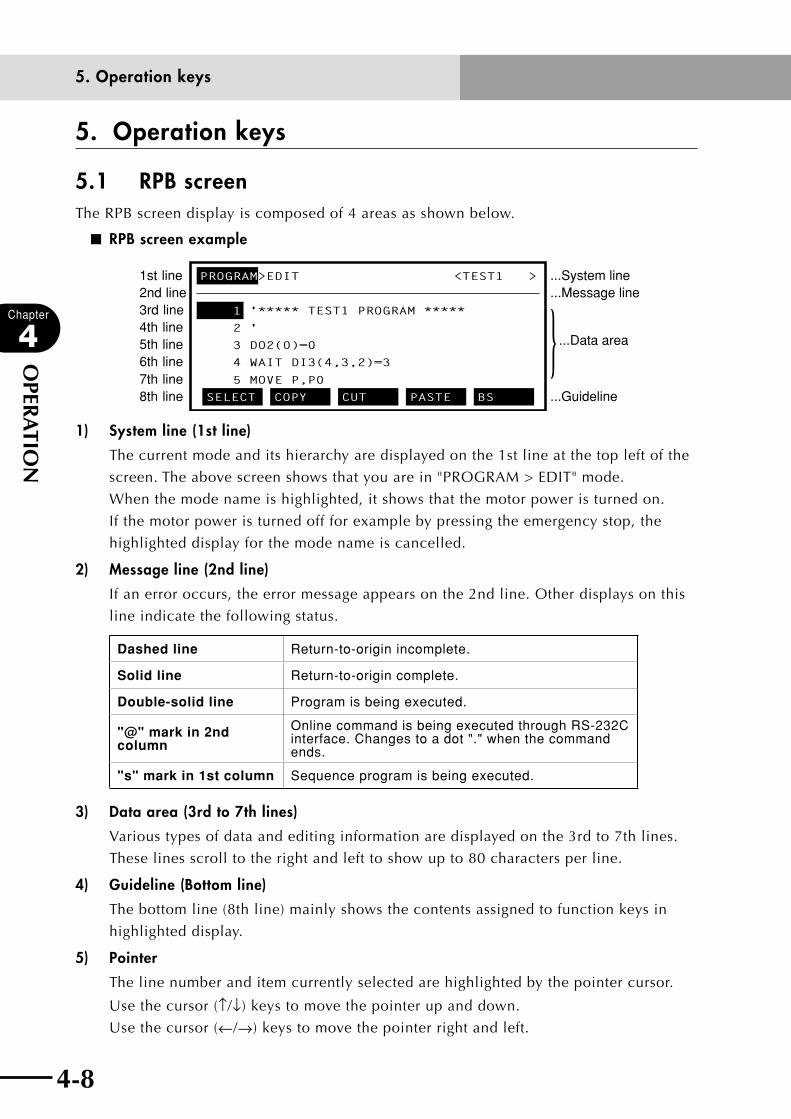
4-8
Chapter
4
OPER
ATIO
N
4-9
5. Operation keys
5.1 RPB screenThe RPB screen display is composed of 4 areas as shown below.
■ RPB screen example
PROGRAM>EDIT <TEST1 >
'***** TEST1 PROGRAM *****
2 '
3 DO2(0)=0
4 WAIT DI3(4,3,2)=3
5 MOVE P,P0
SELECT COPY CUT PASTE BS
1st line2nd line3rd line4th line5th line6th line7th line8th line
...System line
...Message line
...Guideline
...Data area} 1
1) System line (1st line)
The current mode and its hierarchy are displayed on the 1st line at the top left of the
screen. The above screen shows that you are in "PROGRAM > EDIT" mode.
When the mode name is highlighted, it shows that the motor power is turned on.
If the motor power is turned off for example by pressing the emergency stop, the
highlighted display for the mode name is cancelled.
2) Message line (2nd line)
If an error occurs, the error message appears on the 2nd line. Other displays on this
line indicate the following status.
Dashed line Return-to-origin incomplete.
Solid line Return-to-origin complete.
Double-solid line Program is being executed.
"@" mark in 2nd column
Online command is being executed through RS-232Cinterface. Changes to a dot "." when the command ends.
"s" mark in 1st column Sequence program is being executed.
3) Data area (3rd to 7th lines)
Various types of data and editing information are displayed on the 3rd to 7th lines.
These lines scroll to the right and left to show up to 80 characters per line.
4) Guideline (Bottom line)
The bottom line (8th line) mainly shows the contents assigned to function keys in
highlighted display.
5) Pointer
The line number and item currently selected are highlighted by the pointer cursor.
Use the cursor (↑/↓) keys to move the pointer up and down.
Use the cursor (←/→) keys to move the pointer right and left.
5. Operation keys
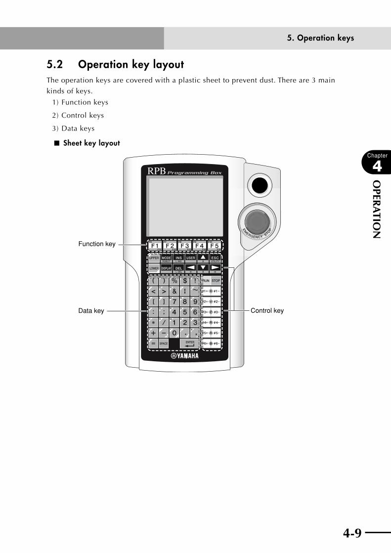
4-8 4-9
Chapter
4
OPER
ATIO
N
5.2 Operation key layoutThe operation keys are covered with a plastic sheet to prevent dust. There are 3 main
kinds of keys.
1) Function keys
2) Control keys
3) Data keys
■ Sheet key layout
Function key
Data key Control key
5. Operation keys
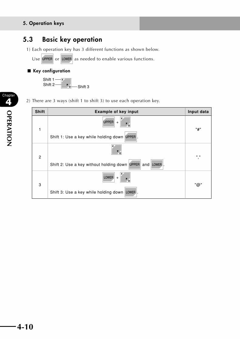
4-10
Chapter
4
OPER
ATIO
N
4-11
5.3 Basic key operation1) Each operation key has 3 different functions as shown below.
Use or as needed to enable various functions.
■ Key configuration
Shift 1Shift 2 Shift 3
2) There are 3 ways (shift 1 to shift 3) to use each operation key.
Shift Example of key input Input data
1
+
Shift 1: Use a key while holding down .
"#"
2
Shift 2: Use a key without holding down and .
","
3
+
Shift 3: Use a key while holding down .
"@"
5. Operation keys

4-10 4-11
Chapter
4
OPER
ATIO
N
5.4 Function keysTo operate the RPB, select the menus by pressing the function keys.
The relation of the function keys to their menus in "MANUAL" mode is shown below.
Function key Selected menu
(F1) POINT
(F2) PALLET
(F3) ORIGIN
(F4) VEL +
(F5) VEL -
+ (F6) SHIFT
+ (F7) HAND
+ (F8) UNITCHG
+ (F9) VEL ++
+ (F10) VEL --
+ (F15) COORDI
5. Operation keys
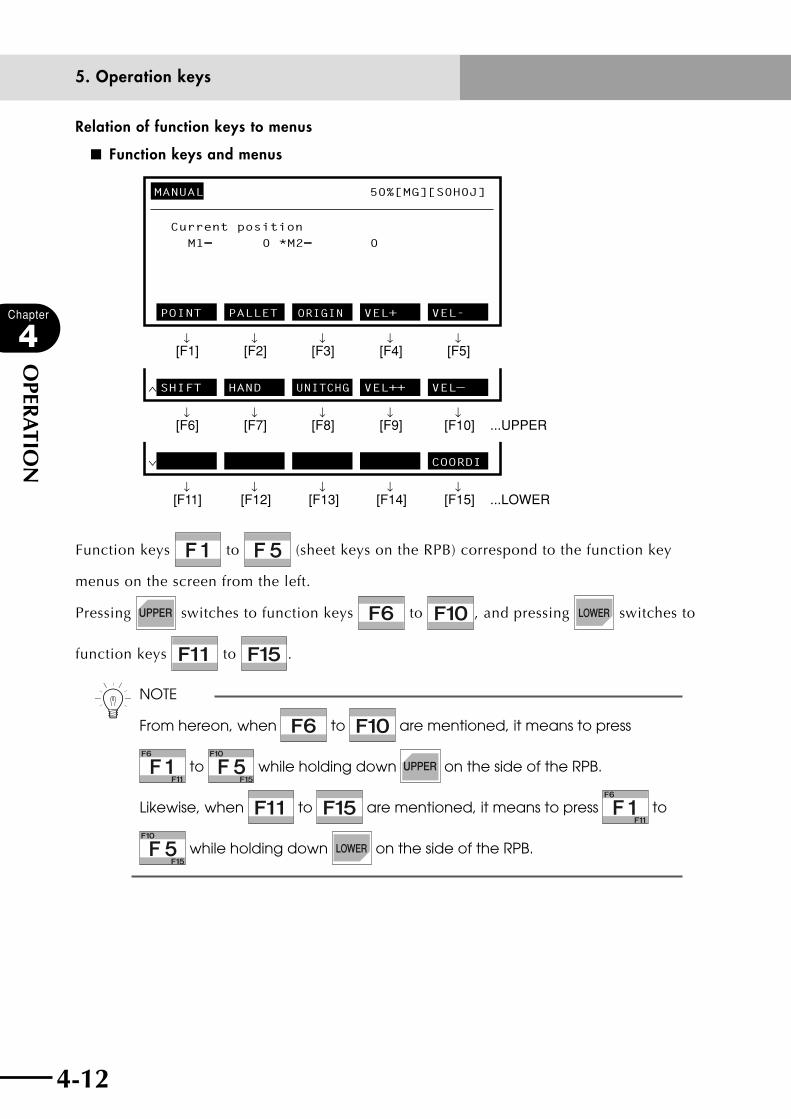
4-12
Chapter
4
OPER
ATIO
N
4-13
Relation of function keys to menus
■ Function keys and menus
MANUAL 50%[MG][S0H0J]
Current position
POINT PALLET VEL+ VEL-
↓ ↓ ↓ ↓ ↓[F1] [F2] [F3] [F4] [F5]
∧ SHIFT HAND UNITCHG VEL++ VEL—
↓ ↓ ↓ ↓ ↓[F6] [F7] [F8] [F9] [F10] ...UPPER
∨
ORIGIN
COORDI
↓ ↓ ↓ ↓ ↓[F11] [F12] [F13] [F14] [F15] ...LOWER
M1= 0 *M2= 0
Function keys to (sheet keys on the RPB) correspond to the function key
menus on the screen from the left.
Pressing switches to function keys to , and pressing switches to
function keys to .
n NOTE
From hereon, when to are mentioned, it means to press
to while holding down on the side of the RPB.
Likewise, when to are mentioned, it means to press to
while holding down on the side of the RPB.
5. Operation keys

4-12 4-13
Chapter
4
OPER
ATIO
N
5.5 Control keysThere are 6 kinds of control keys: (1) Mode selection keys, (2) Extended function keys,
(3) Cursor keys, (4) Page keys, (5) Edit keys, (6) Jog keys.
The functions of each key are explained below.
(1) Mode selection keys
: Displays the mode menu (highest hierarchy).
: Selects the robot I/O monitor screen.
: Selects "UTILITY" mode.
(2) Extended function keys
: Calls up the function key assigned by the user.
: Switches robots.
: Returns to the previous screen (upper hierarchy).
(3) Cursor keys
: Moves the cursor up.
Moves the pointer (highlighted line number display) up when not editing on the screen.
: Moves the cursor down.
Moves the pointer (highlighted line number display) down when not editing on the screen.
: Moves the cursor to the left. (Screen scrolls to the right when the cursor reaches the left end.)
Scrolls the screen to the right when not edited.
: Moves the cursor to the right. (Screen scrolls to the left when the cursor reaches the right end.)
Scrolls the screen to the left when not edited.
(4) Page keys
: Returns to the previous screen.
: Switches to the next screen.
: Switches to the left-hand screen.
: Switches to the right-hand screen.
5. Operation keys
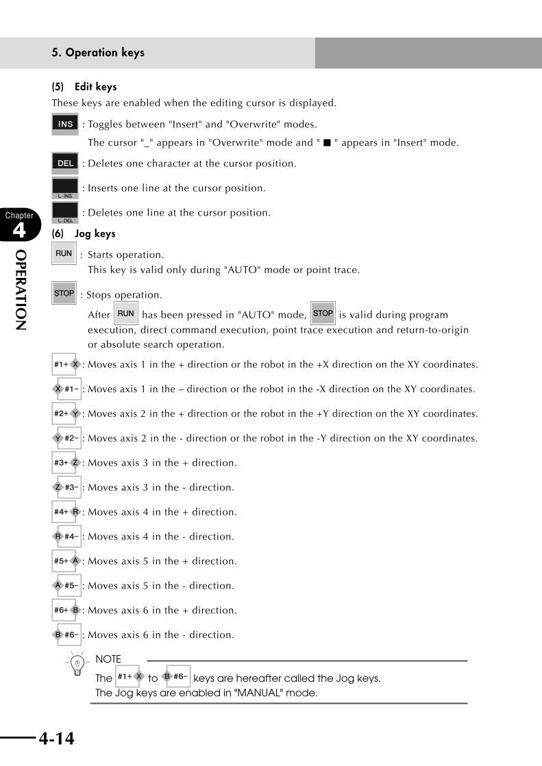
4-14
Chapter
4
OPER
ATIO
N
4-15
(5) Edit keysThese keys are enabled when the editing cursor is displayed.
: Toggles between "Insert" and "Overwrite" modes.
The cursor "_" appears in "Overwrite" mode and " ■ " appears in "Insert" mode.
: Deletes one character at the cursor position.
: Inserts one line at the cursor position.
: Deletes one line at the cursor position.
(6) Jog keys
: Starts operation.
This key is valid only during "AUTO" mode or point trace.
: Stops operation.
After has been pressed in "AUTO" mode, is valid during program
execution, direct command execution, point trace execution and return-to-origin or absolute search operation.
: Moves axis 1 in the + direction or the robot in the +X direction on the XY coordinates.
: Moves axis 1 in the – direction or the robot in the -X direction on the XY coordinates.
: Moves axis 2 in the + direction or the robot in the +Y direction on the XY coordinates.
: Moves axis 2 in the - direction or the robot in the -Y direction on the XY coordinates.
: Moves axis 3 in the + direction.
: Moves axis 3 in the - direction.
: Moves axis 4 in the + direction.
: Moves axis 4 in the - direction.
: Moves axis 5 in the + direction.
: Moves axis 5 in the - direction.
: Moves axis 6 in the + direction.
: Moves axis 6 in the - direction.
n NOTE
The to keys are hereafter called the Jog keys. The Jog keys are enabled in "MANUAL" mode.
5. Operation keys
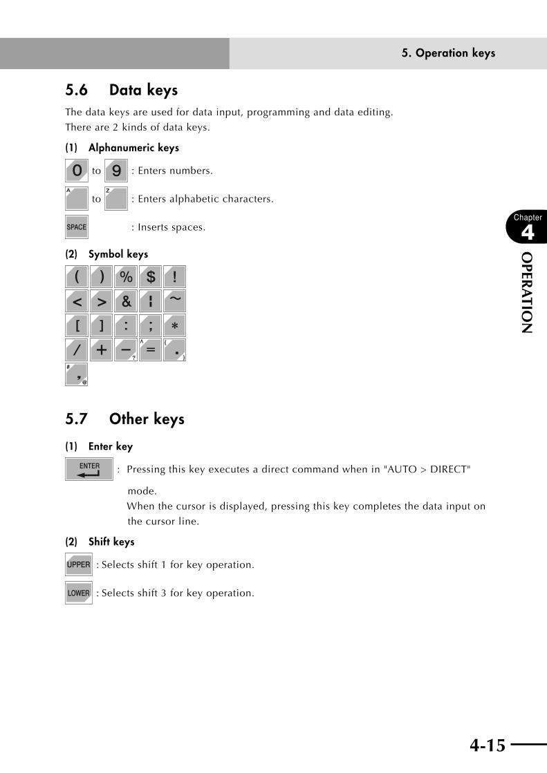
4-14 4-15
Chapter
4
OPER
ATIO
N
5.6 Data keysThe data keys are used for data input, programming and data editing.
There are 2 kinds of data keys.
(1) Alphanumeric keys
to : Enters numbers.
to : Enters alphabetic characters.
: Inserts spaces.
(2) Symbol keys
5.7 Other keys
(1) Enter key
: Pressing this key executes a direct command when in "AUTO > DIRECT"
mode.
When the cursor is displayed, pressing this key completes the data input on
the cursor line.
(2) Shift keys
: Selects shift 1 for key operation.
: Selects shift 3 for key operation.
5. Operation keys
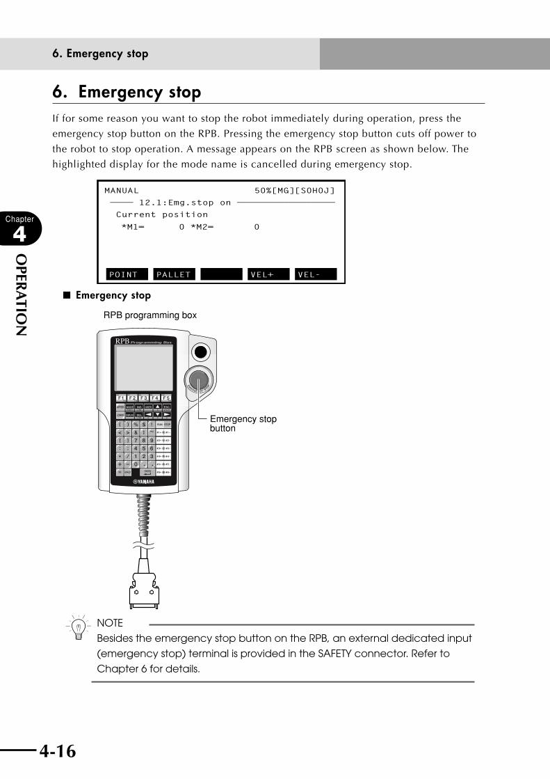
4-16
Chapter
4
OPER
ATIO
N
4-17
6. Emergency stopIf for some reason you want to stop the robot immediately during operation, press the
emergency stop button on the RPB. Pressing the emergency stop button cuts off power to
the robot to stop operation. A message appears on the RPB screen as shown below. The
highlighted display for the mode name is cancelled during emergency stop.
MANUAL 50%[MG][S0H0J]
———— 12.1:Emg.stop on —————————————————
Current position
POINT PALLET VEL+ VEL-
*M1= 0 *M2= 0
■ Emergency stop
RPB programming box
Emergency stop button
n NOTE
Besides the emergency stop button on the RPB, an external dedicated input
(emergency stop) terminal is provided in the SAFETY connector. Refer to
Chapter 6 for details.
6. Emergency stop
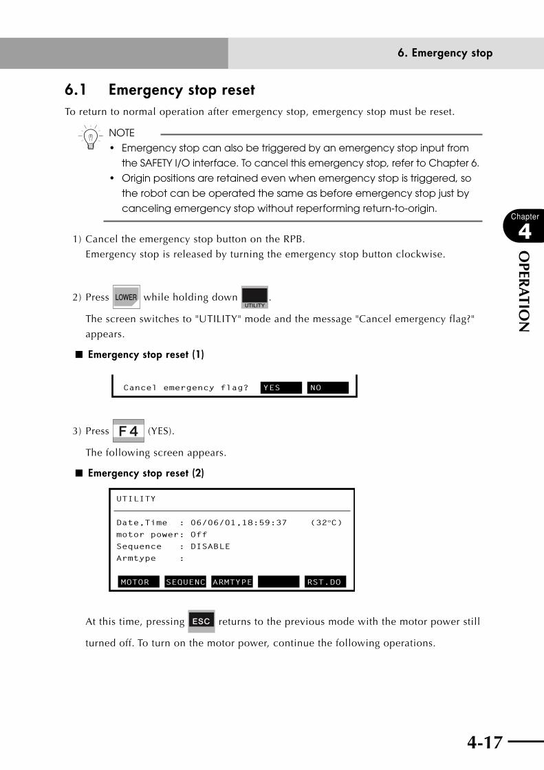
4-16 4-17
Chapter
4
OPER
ATIO
N
6.1 Emergency stop resetTo return to normal operation after emergency stop, emergency stop must be reset.
n NOTE
• Emergency stop can also be triggered by an emergency stop input from
the SAFETY I/O interface. To cancel this emergency stop, refer to Chapter 6.
• Originpositionsareretainedevenwhenemergencystopistriggered,so
the robot can be operated the same as before emergency stop just by
canceling emergency stop without reperforming return-to-origin.
1) Cancel the emergency stop button on the RPB.
Emergency stop is released by turning the emergency stop button clockwise.
2) Press while holding down .
The screen switches to "UTILITY" mode and the message "Cancel emergency flag?"
appears.
■ Emergency stop reset (1)
Cancel emergency flag? YES NO
3) Press (YES).
The following screen appears.
■ Emergency stop reset (2)
UTILITY
Date,Time : 06/06/01,18:59:37 (32°C)motor power: Off
Sequence : DISABLE
Armtype :
MOTOR SEQUENC ARMTYPE RST.DO
At this time, pressing returns to the previous mode with the motor power still
turned off. To turn on the motor power, continue the following operations.
6. Emergency stop
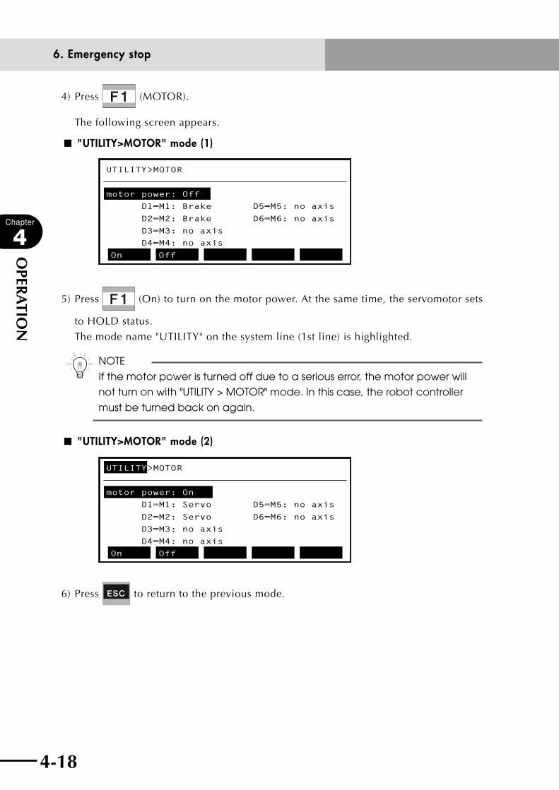
4-18
Chapter
4
OPER
ATIO
N
4-19
4) Press (MOTOR).
The following screen appears.
■ "UTILITY>MOTOR" mode (1)
UTILITY>MOTOR
motor power: Off
D1=M1: Brake D5=M5: no axis
D2=M2: Brake D6=M6: no axis
D3=M3: no axis
D4=M4: no axis
On Off
5) Press (On) to turn on the motor power. At the same time, the servomotor sets
to HOLD status.
The mode name "UTILITY" on the system line (1st line) is highlighted.
n NOTE
If the motor power is turned off due to a serious error, the motor power will
not turn on with "UTILITY > MOTOR" mode. In this case, the robot controller
must be turned back on again.
■ "UTILITY>MOTOR" mode (2)
UTILITY>MOTOR
motor power: On
D1=M1: Servo D5=M5: no axis
D2=M2: Servo D6=M6: no axis
D3=M3: no axis
D4=M4: no axis
On Off
6) Press to return to the previous mode.
6. Emergency stop

4-18 4-19
Chapter
4
OPER
ATIO
N
7. Mode configurationThe robot operation mode consists of the following modes.
“SERVICE” mode
Basic operation modes
“AUTO”mode
“MANUAL”mode
“PROGRAM”mode
“SYSTEM”mode
“DI/DOmonitor”
mode
“UTILITY”mode
"SERVICE" mode can be used only when "SAFE" mode is enabled.
7.1 Basic operation modes Robot operation is classified into 5 basic modes as follows.
(1) "SERVICE" mode (only when "SAFE" mode is enabled)
(2) "AUTO" mode
(3) "PROGRAM" mode
(4) "MANUAL" mode
(5) "SYSTEM" mode
Among these modes, "SERVICE" mode can be selected with DI02 ("SERVICE" mode input)
and other modes with the function keys.
(1) "SERVICE" mode
"SERVICE" mode is used to perform maintenance work using the RPB safely within
the safety enclosure of the robot system. This mode includes "AUTO" and "MANUAL"
modes in the basic operation mode, and can be selected by turning DI02 ("SERVICE"
mode input) OFF. The following functions are selected in "SERVICE" mode.
1. Robot is controlled only by RPB operation.
2. Automatic operation is prohibited.
3. Robot operating speed is set to below 3% of the maximum speed.
4. Robot operation is possible only by hold-to-run control.
cCAUTIONThe "SYSTEM" mode is used to select the "SERVICE" mode functions. (Refer to '12.3.2 Setting the "SERVICE" mode' in this chapter.)
7. Mode configuration

4-20
Chapter
4
OPER
ATIO
N
4-21
(2) "AUTO" mode
Select this mode to execute robot programs. Robot programs can be executed only in
this mode. Operable tasks in this mode differ depending on the parameter settings in
"SERVICE" mode.
(3) "PROGRAM" mode
Select this mode to create and edit robot programs. Robot programs can be edited on
the RPB screen.
(4) "MANUAL" mode
Select this mode to move the robot manually or perform point teaching. Return-to-
origin or absolute search operation and manual movement can be executed only in
this mode.
Operable tasks in this mode differ depending on the parameter settings in "SERVICE"
mode.
n NOTE
• Return-to-origincanbeperformedonlyin"MANUAL"mode.
• "AUTO"modemaybeselecteddependingontheexecutionlevelwhen
the robot controller is turned on.
(5) "SYSTEM" mode
Select this mode to perform maintenance and adjustment of the YAMAHA robots such
as robot parameter and axis parameter settings.
7.2 Other operation modesOther than the basic operation modes the following two modes are also available.
(1) "DI/DO Monitor" mode
(2) "UTILITY" mode
These modes can be selected with the control keys.
(1) "DI/DO Monitor" mode
Use this mode to monitor the robot controller I/O status or task status on the RPB
screen. Use to select this mode.
(2) "UTILITY" mode
Use this mode to perform maintenance of the YAMAHA robots such as recovery from
emergency stop and motor servo on/off switching. Use to select this mode.
7. Mode configuration

4-20 4-21
Chapter
4
OPER
ATIO
N
7.3 Mode hierarchyRobot operation is mainly performed by pressing the function keys to select the desired
mode from the menu. (Refer to the "Mode hierarchy diagram" described later.)
When the controller is turned on, the "MANUAL" mode menu first appears on the screen.
Pressing displays the 4 basic modes on the guideline (bottom line) of the screen as
shown below.
■ Mode menu
MANUAL 50% [MG][S0H0J]
Current position
AUTO PROGRAM MANUAL SYSTEM
*M1= 0 *M2= 0
These are basic modes at the highest hierarchy on the menu. The display position for each
mode name corresponds to each function key of , , and from
the left.
For example, when (AUTO) is pressed, "AUTO" mode is entered.
■ "AUTO" mode menu
AUTO [T1] 100% <TEST1 >
1 ’***** TEST1 PROGRAM *****
2 ’
3 DO2(0)=0
4 WAIT DI3(4,3,2)=3
5 MOVE P,P0
RESET TASK DIR VEL+ VEL-
When "AUTO" mode is entered, the submenu for the "AUTO" mode operation appears on
the guideline.
The submenu also corresponds to the function keys from to . (See the figure
titled "Function switching" on the next page.)
7. Mode configuration

4-22
Chapter
4
OPER
ATIO
N
4-23
Functions are switched with the and shift keys. The menu display changes
while this shift key is pressed.
■ Shift keys
■ Function switching
RESET TASK DIR VEL+ VEL-
↓ ↓ ↓ ↓[F1]
↓[F2] [F3] [F4] [F5]
∧ POINT DIRECT BREAK VEL++ VEL--
↓ ↓ ↓ ↓ ↓[F6] [F7] [F8] [F9] [F10]
∨ STEP SKIP NEXT
↓ ↓ ↓[F11] [F12] [F13]
.
...when is pressed.
........................................when is pressed.
The " " mark at the left end on the guideline shows that is pressed, while the " "
mark shows that is pressed.
Some submenus have other menus for accessing the next hierarchical mode.
For example, pressing in "AUTO" mode while holding down , switches to
"BREAK" mode. Submenus relating to "BREAK" mode then appear.
As explained above, operation can proceed through each hierarchy by selecting the menu
items with the function keys. To return to the previous mode hierarchy, press .
To return to a highest mode press . The basic modes are then displayed on the
guideline, so select the desired basic mode by pressing the corresponding function key.
7. Mode configuration
4-22 4-23
Chapter
4
OPER
ATIO
N
n NOTE
• Whenthedataisbeingeditedsuchasin"EDIT"mode, is
inoperative. After pressing to return the mode hierarchy, press
.
• Fromhereinthisuser'smanualthemodehierarchystatusisstatedintheorder as shown below.
First (highest) hierarchy > Second hierarchy > Third hierarchy > Fourth hierarchy Example: PROGRAM > DIR>ERASE
The above example shows that the current mode is entered by selecting
(PROGRAM) from the first hierarchy menu, (DIR) from the
second hierarchy menu and (ERASE) from the third hierarchy
menu.
See the figure titled "Mode hierarchy diagram" on the next page for the entire mode
hierarchy.
7. Mode configuration
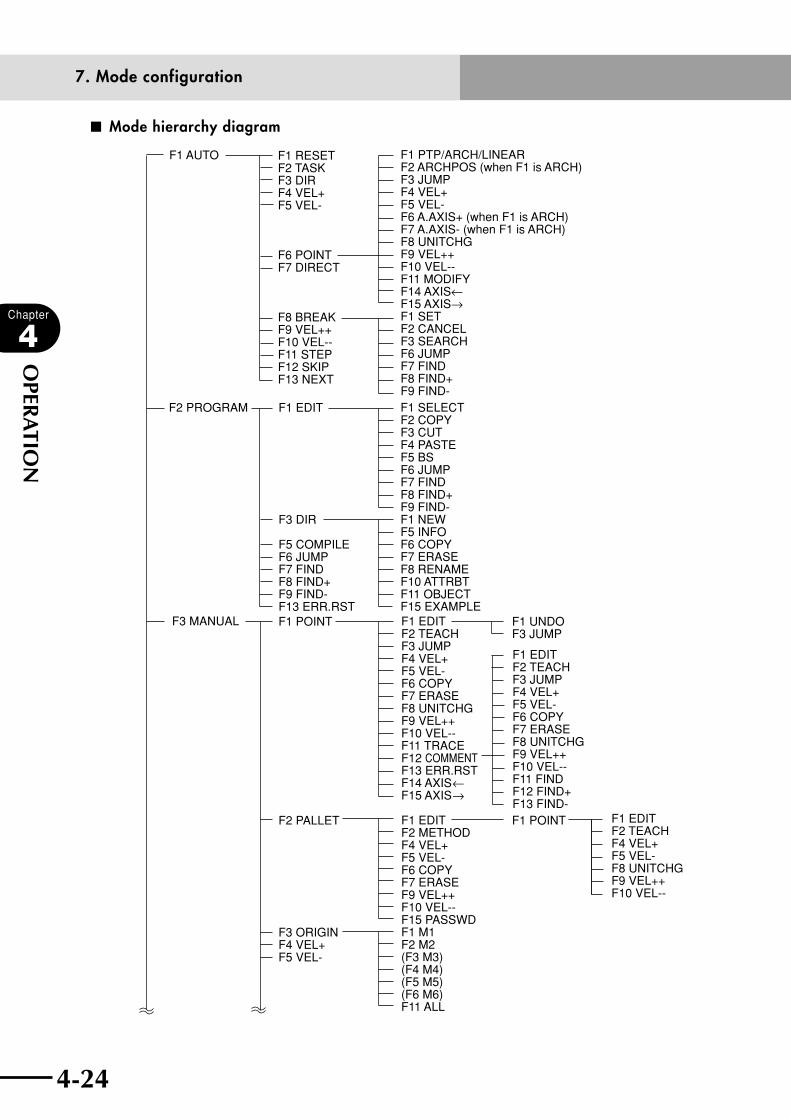
4-24
Chapter
4
OPER
ATIO
N
4-25
■ Mode hierarchy diagram
F1 AUTO
F1 EDITF2 TEACHF3 JUMPF4 VEL+F5 VEL-F6 COPYF7 ERASEF8 UNITCHGF9 VEL++F10 VEL--F11 FINDF12 FIND+F13 FIND-
F1 UNDOF3 JUMP
F1 POINT
F1 EDITF2 TEACHF3 JUMPF4 VEL+F5 VEL-F6 COPYF7 ERASEF8 UNITCHGF9 VEL++F10 VEL--F11 TRACEF12 COMMENTF13 ERR.RSTF14 AXIS←F15 AXIS→
F1 EDITF2 METHODF4 VEL+F5 VEL-F6 COPYF7 ERASEF9 VEL++F10 VEL--F15 PASSWDF1 M1F2 M2(F3 M3)(F4 M4)(F5 M5)(F6 M6)F11 ALL
F2 PROGRAM
F1 EDITF2 TEACHF4 VEL+F5 VEL-F8 UNITCHGF9 VEL++F10 VEL--
F3 MANUAL
F1 RESETF2 TASKF3 DIRF4 VEL+F5 VEL-
F6 POINTF7 DIRECT
F8 BREAKF9 VEL++F10 VEL--F11 STEPF12 SKIPF13 NEXT
F1 EDIT
F3 DIR
F5 COMPILEF6 JUMPF7 FINDF8 FIND+F9 FIND-F13 ERR.RSTF1 POINT
F2 PALLET
F3 ORIGINF4 VEL+F5 VEL-
F1 PTP/ARCH/LINEARF2 ARCHPOS (when F1 is ARCH) F3 JUMPF4 VEL+F5 VEL-F6 A.AXIS+ (when F1 is ARCH) F7 A.AXIS- (when F1 is ARCH) F8 UNITCHGF9 VEL++F10 VEL--F11 MODIFYF14 AXIS←F15 AXIS→F1 SETF2 CANCELF3 SEARCHF6 JUMPF7 FINDF8 FIND+F9 FIND-F1 SELECTF2 COPYF3 CUTF4 PASTEF5 BSF6 JUMPF7 FINDF8 FIND+F9 FIND-F1 NEWF5 INFOF6 COPYF7 ERASEF8 RENAMEF10 ATTRBTF11 OBJECTF15 EXAMPLE
7. Mode configuration

4-24 4-25
Chapter
4
OPER
ATIO
N
F1 EDITF4 VEL+F5 VEL-F6 METHOD1F8 UNITCHGF9 VEL++F10 VEL--F1 4POINTSF2 3POINTSF5 SIMPLE
F4 VEL+F5 VEL-F8 UNITCHGF9 VEL++F10 VEL--F4 VEL+F5 VEL-F8 UNITCHGF9 VEL++F10 VEL--
F4 VEL+F5 VEL-F8 UNITCHGF9 VEL++F10 VEL--
F1 EDITF2 RANGEF4 VEL+F5 VEL-F6 METHOD1
F7 METHOD2F9 VEL++F10 VEL--
F3 MANUAL F6 SHIFT
F7 HANDF8 UNITCHGF9 VEL++F10 VEL--
F15 COORDI
F1 ROBOT
F2 AXIS
F3 OTHER
F5 OP. BRDF10 PASSWRDF1 EDITF2 JUMPF1 POS.OUT
F2 SERVICE
F3 SIOF4 W.CAREER
F4 SYSTEM F1 EDITF2 JUMPF1 EDITF2 JUMPF1 EDITF2 JUMP
F1 EDITF2 JUMPF1 EDITF2 JUMPF4 SAVEF5 HELPF1 EDITF2 JUMP
F1 PARAM
F2 CMU
F3 OPTION
F4 INIT
F5 DIAGNOS
F9 BACKUPF15 DRV.UP
F1 PROGRAMF2 POINTF3 SHIFTF4 HANDF5 ALLF6 PALETTEF7 COMMENTF1 DATEF2 TIMEF1 ROBOTF2 AXISF4 CLEARF5 HELPF6 AUXF7 DUALF15 LAYOUT
UTILITY 1 F1 MOTORF2 SEQUENCF3 ARMTYPEF5 RST.DOF9 DSW.HLPF10 DIO.HLPF1 EXECUTEF2 ACCESSF5 RST.DOF9 DSW.HLPF10 DIO.HLP
UTILITY 2
DISPLAY
F1 PARAMF2 MEMORY
F3 CMU
F4 CLOCK
F6 GENERATF10 PASSWRDF1 CHECKF2 HISTORYF3 BATTERYF5 TOTALF15 SYS. CHKF4 SDCARDF5 FROM
7. Mode configuration

4-26
Chapter
4
OPER
ATIO
N
4-27
8. "SERVICE" mode
8. "SERVICE" mode"SERVICE" mode can be used only when "SAFE" mode is enabled.
Use "SERVICE" mode to perform safe maintenance work with the RPB while within the
safety enclosure of the robot system. This mode can be selected by turning DI02 ("SERVICE"
mode input) OFF.
cCAUTION• use"sYsteM"modetoselectthefunctionsin"service"mode.(referto
'12.3.2 Setting the "SERVICE" mode' in this chapter.)• Basically, RPB operation is only allowed in "SERVICE" mode, so application
software (VIP/WIN, etc.) that executes on-line commands through the RS-232C interface cannot be used, except for cases where other operating devices are enabled by on-line commands made via the RS-232C.
8.1 Operation deviceIf operation from a device other than the RPB is permitted, the operator using the RPB may
be exposed to hazardous situations. For example:
1. When a dedicated input start signal is turned ON without the RPB operator
knowing about it.
2. When an external device runs a robot operation command through the RS-232C
interface without the RPB operator knowing about it.
To prevent this kind of accident in "SERVICE" mode, only the RPB can be used to operate
the robot and other operation devices are disabled. However, you may add other operation
devices provided you take responsibility for your own safety.
8.2 Prohibition of "AUTO" mode operationA major purpose for robot operation while the operator is working within the safety
enclosure is maintenance and adjustment of the robot. If a robot program is executed
in "AUTO" mode during maintenance work, the robot might move on its own with no
warning to the operator. Therefore, "AUTO" mode operation is basically prohibited in
"SERVICE" mode. However, if robot movement in a program must be checked while the
operator stays within the safety enclosure, then "AUTO" mode can be selected provided
you take responsibility for your own safety.
8.3 Hold-to-Run functionIf the robot operator using the RPB should trip or fall during maintenance work, he (she)
might be exposed to a dangerous situation. To prevent this kind of accident, the Hold-
to-Run function allows the robot to move only during the time that the RPB key is kept
pressed (like a deadman switch.). However, the Hold-to-Run function can be turned OFF
provided you take responsibility for your own safety.

4-26 4-27
Chapter
4
OPER
ATIO
N
8. "SERVICE" mode
8.4 Limitations on robot operating speedA major purpose of robot operation while the operator is working within the safety
enclosure is maintenance and adjustment of the robot. If a dangerous situation should
occur, the operator can easily avoid it if the robot operating speed is maintained within
250mm/sec.
The robot operating speed in "SERVICE" mode is therefore basically limited to below 3%
of maximum speed. However, if the robot operating speed has to be set higher than the
safety range while the operator is still within the safety enclosure, this speed limitation
can be cancelled provided you take responsibility for your own safety.
cCAUTIONWhen operating the robot without using the safety functions explained in sections 8.2, 8.3 and 8.4 while the operator is still within the safety enclosure, it is important to take even more stringent safety precautions.

4-28
Chapter
4
OPER
ATIO
N
4-29
9. "AUTO" mode
9. "AUTO" mode"AUTO" mode executes robot language programs and related tasks.
The initial "AUTO" mode screen is shown below.
■ "AUTO" mode
AUTO [T1] 100% <TEST1 >
s@ —————————————————————————————————————
1 ’***** TEST1 PROGRAM *****
2 START *SUBTASK,T2
3 DO2(0)=0
4 WAIT DI3(4,3,2)=3
5 MOVE P,P0
RESET TASK DIR VEL+ VEL-
qMode hierarchy wTask display
eAutomatic movement speed rProgram name
tMessage line
yOnline command execution mark
uSequence program execution mark
iPointer display
oGuideline
q Mode hierarchy
Shows the current mode hierarchy. When the highest mode ("AUTO" in this case) is
not highlighted, it means the servomotor power is off. When highlighted, it means the
servomotor power is on.
w Task display
Shows the task number for the program listing being displayed.
e Automatic movement speed
Robot movement speed is displayed during automatic operation.
r Program name
Shows the program name currently selected.
t Message line
If an error occurs, the error message appears here. A dashed line means return-to-
origin is incomplete. A solid line means return-to-origin return is complete. A double-
solid line means automatic operation is in progress.
y Online command execution mark
When an online command is being executed, an "@" mark is displayed in the second
column on the second line. This mark changes to a dot "." when the online command
ends.
u Sequence program execution mark
When a sequence program is being executed, an "s" mark is displayed in the first
column on the second line.

4-28 4-29
Chapter
4
OPER
ATIO
N
9. "AUTO" mode
i Pointer display
The program line number to be executed next is shown highlighted in the program
listing.
o Guideline
The contents assigned to function keys are shown highlighted. A message on what to
do next also appears here in some operation steps.
Upon entering "AUTO" mode, the specified program is compiled and an object file is
created to execute automatic operation.
When the same object file already exists, no compiling is executed.
If an error is found in a command statement during compiling, the error message and
the program listing after the command line where the error occurred are displayed.
If the compiling ends normally, the program listing is displayed from the top
command line.
n NOTE
Usually, return-to-origin must be completed before starting "AUTO" mode. If
return-to-origin is not complete, the message "Origin incomplete" appears.
In such a case, refer to "11.8 Return-to-origin" later in this chapter.
However, the program can be executed depending on the command
execution level even if return-to-origin has not been completed. For further
information, see the execution level explained in section "14.4 Changing the
execution level" later in this chapter.
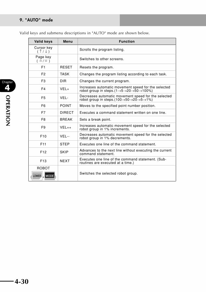
4-30
Chapter
4
OPER
ATIO
N
4-31
9. "AUTO" mode
Valid keys and submenu descriptions in "AUTO" mode are shown below.
Valid keys Menu Function
Cursor key ( ↑ / ↓ ) Scrolls the program listing.
Page key (
〈〈 / 〈〈 ) Switches to other screens.
F1 RESET Resets the program.
F2 TASK Changes the program listing according to each task.
F3 DIR Changes the current program.
F4 VEL+ Increases automatic movement speed for the selected robot group in steps.(1→5→20→50→100%)
F5 VEL- Decreases automatic movement speed for the selected robot group in steps.(100→50→20→5→1%)
F6 POINT Moves to the specified point number position.
F7 DIRECT Executes a command statement written on one line.
F8 BREAK Sets a break point.
F9 VEL++ Increases automatic movement speed for the selected robot group in 1% increments.
F10 VEL-- Decreases automatic movement speed for the selected robot group in 1% decrements.
F11 STEP Executes one line of the command statement.
F12 SKIP Advances to the next line without executing the current command statement.
F13 NEXT Executes one line of the command statement. (Sub-routines are executed at a time.)
ROBOT
( + )Switches the selected robot group.

4-30 4-31
Chapter
4
OPER
ATIO
N
9. "AUTO" mode
9.1 Automatic operationProgram commands are executed continuously during automatic operation. Before starting
automatic operation, make sure that return-to-origin, program debugging, I/O signal
connections and point data teaching have already been completed. When the execution
level is set to other than level 0, automatic operation is possible even if return-to-origin is
incomplete.
n NOTE
Regardless of the execution level, some commands such as the robot
movement commands cannot be executed if return-to-origin is incomplete.
When the execution level 5, 6 or 8 is selected, the program will always be
executed from the beginning.
[Procedure]
Press in "AUTO" mode.
Command statements are executed in order from the line number where the pointer is
displayed.
The program listing disappears during automatic operation and the message "Running"
appears on the message line (the second line).
The message line changes from a single solid line to a double-solid line when automatic
operation starts.
wWARNING
• uponpressing , THE ROBOT STARTS TO MOVE. TO AVOID DANGER,
DO NOT ENTER THE ROBOT MOVEMENT RANGE.• wHencHAngingtHeAutoMAticMoveMentspeedduringAutoMAtic
OPERATION, CHECk SAFETY FOR SURROUNDING AREAS.
■ Automatic operation in progress
AUTO [T1] 100% <TEST1 >
0.2:Running
RESET TASK DIR VEL+ VEL-

4-32
Chapter
4
OPER
ATIO
N
4-33
9. "AUTO" mode
The following keys are enabled during automatic operation.
Valid keys Menu Function
F9 VEL++ Increases automatic movement speed for the selected robot group in 5% increments.
F10 VEL-- Decreases automatic movement speed for the selected robot group in 5% decrements.
ROBOT
( + )Switches the selected robot group.
n NOTE
When automatic movement speed was changed during automatic
operation, it is enabled after the automatic operation is complete.
9.2 Stopping the program
[Procedure]
1) Press during program execution to stop the program.
cCAUTIONDo not turn off the robot controller during program execution. If turned off, an error may occur in the internal system data and the program might not restart normally when the power is again turned on. Always be sure to terminate or stop the program before turning the power off.
■ Program stop screen
AUTO [T1] 100% <TEST1 >
RESET TASK DIR VEL+ VEL-
2) Press to display the program listing.
The pointer indicates the next command line number to be executed in the program.
3) Press to re-execute the program.
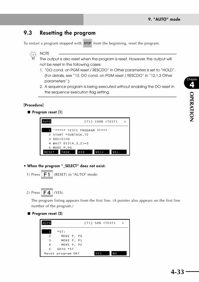
4-32 4-33
Chapter
4
OPER
ATIO
N
9. "AUTO" mode
9.3 Resetting the program
To restart a program stopped with from the beginning, reset the program.
n NOTE
The output is also reset when the program is reset. However, the output will
not be reset in the following cases:
1. “DO cond. on PGM reset / RESCDO” in Other parameters is set to “HOLD”.
(For details, see “13. DO cond. on PGM reset / RESCDO” in “12.1.3 Other
parameters”.)
2. A sequence program is being executed without enabling the DO reset in
the sequence execution flag setting.
[Procedure]
■ Program reset (1)
AUTO [T1] 100% <TEST1 >
1 ’***** TEST1 PROGRAM *****
2 START *SUBTASK,T2
3 DO2(0)=0
4 WAIT DI3(4,3,2)=3
5 MOVE P,P0
RESET TASK DIR VEL+ VEL-
• When the program "_SELECT" does not exist:
1) Press (RESET) in "AUTO" mode.
2) Press (YES).
The program listing appears from the first line. (A pointer also appears on the first line
number of the program.)
■ Program reset (2)
AUTO [T1] 50% <TEST1 >
1 *ST:
2 MOVE P, P0
3 MOVE P, P1
4 MOVE P, P2
5 GOTO *ST
Reset program OK? YES NO

4-34
Chapter
4
OPER
ATIO
N
4-35
9. "AUTO" mode
• When the program "_SELECT" exists:
1) Press (RESET) in "AUTO" mode.
The following message appears on the guideline when "_SELECT" exists among
the programs. Press (YES) to reset the selected program by switching it to
"_SELECT", or press (NO) to just reset the current program.
■ Program reset (3)
AUTO [T1] 50% <TEST1 >
1 *ST:
2 MOVE P, P0
3 MOVE P, P1
4 MOVE P, P2
5 GOTO *ST
Change to _SELECT OK? YES NO
2) When (NO) is pressed in Step 1), the following message then appears on the
guideline.
Press (YES) to reset the current program, or press (NO) to cancel the
reset.
■ Program reset (4)
AUTO [T1] 50% <TEST1 >
1 *ST:
2 MOVE P, P0
3 MOVE P, P1
4 MOVE P, P2
5 GOTO *ST
Reset program OK? YES NO
n NOTE
The output is also reset when the program is reset. However, the output will
not be reset in the following cases:
1. “DO cond. on PGM reset / RESCDO” in Other parameters is set to “HOLD”.
(For details, see “13. DO cond. on PGM reset / RESCDO” in “12.1.3 Other
parameters”.)
2. A sequence program is being executed without enabling the DO reset in
the sequence execution flag setting.
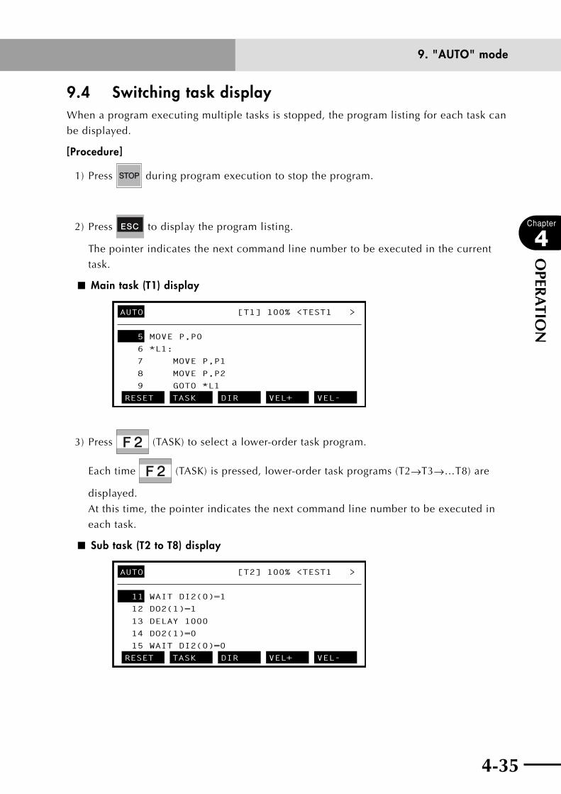
4-34 4-35
Chapter
4
OPER
ATIO
N
9. "AUTO" mode
9.4 Switching task displayWhen a program executing multiple tasks is stopped, the program listing for each task can
be displayed.
[Procedure]
1) Press during program execution to stop the program.
2) Press to display the program listing.
The pointer indicates the next command line number to be executed in the current
task.
■ Main task (T1) display
AUTO [T1] 100% <TEST1 >
5 MOVE P,P0
6 *L1:
7 MOVE P,P1
8 MOVE P,P2
9 GOTO *L1
RESET TASK DIR VEL+ VEL-
3) Press (TASK) to select a lower-order task program.
Each time (TASK) is pressed, lower-order task programs (T2→T3→…T8) are
displayed.
At this time, the pointer indicates the next command line number to be executed in
each task.
■ Sub task (T2 to T8) display
AUTO [T2] 100% <TEST1 >
11 WAIT DI2(0)=1
12 DO2(1)=1
13 DELAY 1000
14 DO2(1)=0
15 WAIT DI2(0)=0
RESET TASK DIR VEL+ VEL-
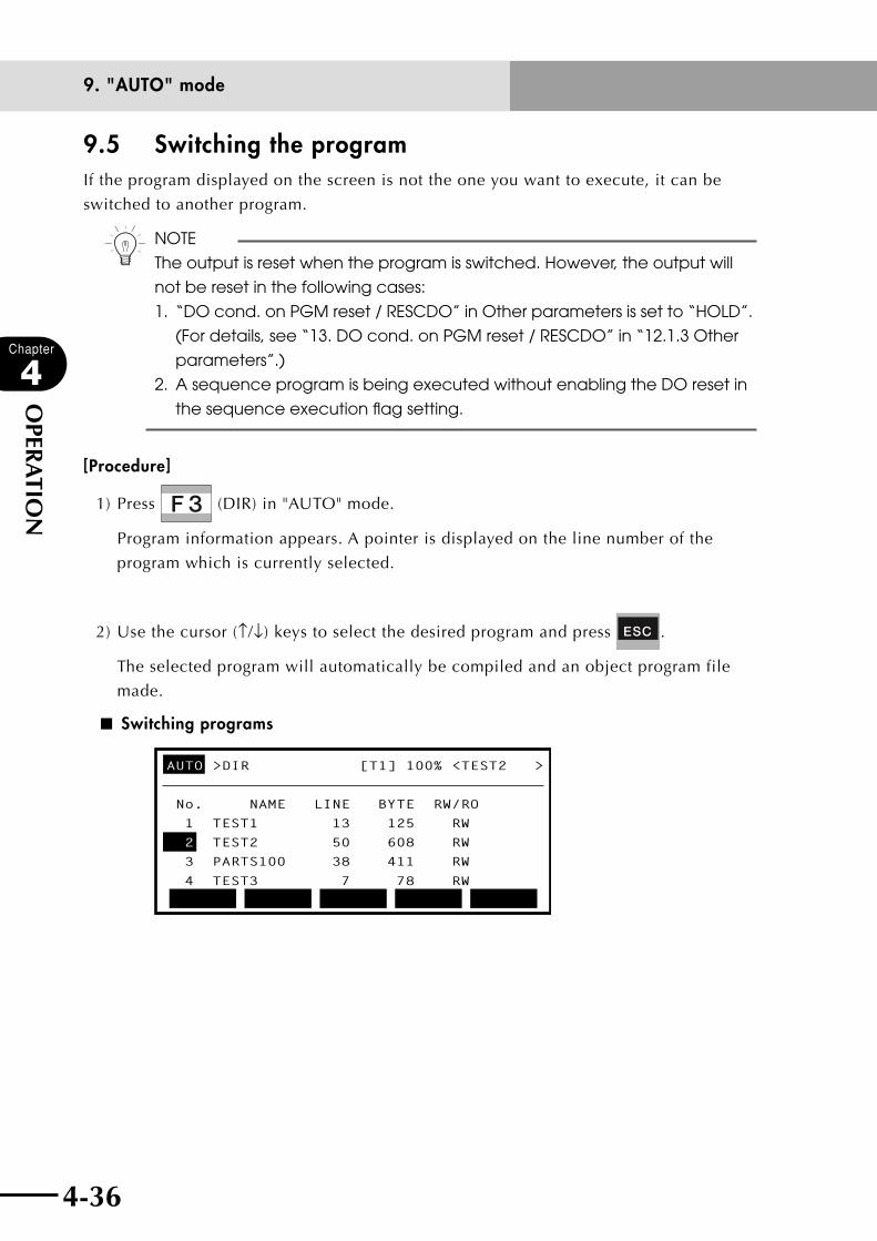
4-36
Chapter
4
OPER
ATIO
N
4-37
9. "AUTO" mode
9.5 Switching the programIf the program displayed on the screen is not the one you want to execute, it can be
switched to another program.
n NOTE
The output is reset when the program is switched. However, the output will
not be reset in the following cases:
1. “DO cond. on PGM reset / RESCDO” in Other parameters is set to “HOLD”.
(For details, see “13. DO cond. on PGM reset / RESCDO” in “12.1.3 Other
parameters”.)
2. A sequence program is being executed without enabling the DO reset in
the sequence execution flag setting.
[Procedure]
1) Press (DIR) in "AUTO" mode.
Program information appears. A pointer is displayed on the line number of the
program which is currently selected.
2) Use the cursor (↑/↓) keys to select the desired program and press .
The selected program will automatically be compiled and an object program file
made.
■ Switching programs
AUTO >DIR [T1] 100% <TEST2 >
No. NAME LINE BYTE RW/RO
1 TEST1 13 125 RW
2 TEST2 50 608 RW
3 PARTS100 38 411 RW
4 TEST3 7 78 RW
4-36 4-37
Chapter
4
OPER
ATIO
N
9. "AUTO" mode
9.6 Changing the automatic movement speedAutomatic movement speed for the selected robot group can be set within the range of 1
to 100%.
n NOTE
Automatic movement speeds once set here are stored in the internal
memory even when the power is turned off.
If the speed is set with the program command statement (SPEED statement),
the actual robot operating speed will be the product of that speed and the
automatic movement speed.
For example, if the automatic movement speed is 80% and the speed
specified by the SPEED statement is 50%, then the robot movement speed is
set as follows.
Operating speed = 80%×50% = 40%
[Procedure]
1) Press (VEL+) or (VEL-) in "AUTO" mode to change the speed in steps.
Each time (VEL+) or (VEL-) is pressed, the speed changes in steps of
1← →5← →20← →50← →100%.
The maximum motor speed is set at 100%.
2) Press (VEL++) or (VEL--) to change the speed gradually.
Each time (VEL++) or (VEL--) is pressed, the speed changes in units of
1%.
Holding down the key changes the speed continuously.
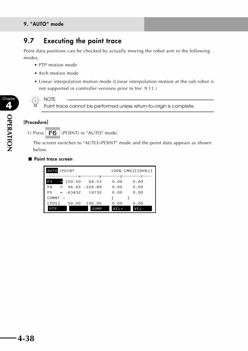
4-38
Chapter
4
OPER
ATIO
N
4-39
9. "AUTO" mode
9.7 Executing the point tracePoint data positions can be checked by actually moving the robot arm in the following
modes.
•PTPmotionmode
•Archmotionmode
•Linearinterpolationmotionmode(Linearinterpolationmotionatthesubrobotis
not supported in controller versions prior to Ver. 9.11.)
n NOTE
Point trace cannot be performed unless return-to-origin is complete.
[Procedure]
1) Press (POINT) in "AUTO" mode.
The screen switches to "AUTO>POINT" mode and the point data appears as shown
below.
■ Point trace screen
AUTO POINT 100% [MG][S0H0J]
————————————x———————y———————z———————r———
P3 = 150.50 64.53
P4 = 96.65 -224.89
P5 = -63432 19735
COMNT : [ ]
[POS] 50.00 100.00 0.00 0.00
0.00 0.00
0.00 0.00
0.00 0.00
PTP JUMP VEL+ VEL-
>

4-38 4-39
Chapter
4
OPER
ATIO
N
9. "AUTO" mode
Valid keys and submenu descriptions in "AUTO > POINT" mode are shown below.
Valid keys Menu Function
Cursor key ( ↑ / ↓ ) Switches the point number and scrolls the screen.
Page key (
〈〈 / 〈〈 ) Switches to other screens.
F1PTP/ARCH/ LINEAR
Switches the trace movement mode.
F2 A.POS Specifies the arch position during ARCH motion mode.
F3 JUMP Displays the specified point data.
F4 VEL+ Increases automatic movement speed for the selected robot group in steps.(1→5→20→50→100%)
F5 VEL- Decreases automatic movement speed for the selected robot group in steps.(100→50→20→5→1%)
F6 A.AXIS+ Moves the arch axis to the right during ARCH motion mode.
F7 A.AXIS- Moves the arch axis to the left during ARCH motion mode.
F8 UNITCHG Switches the units for indicating the current position to "mm/pulse".
F9 VEL++ Increases automatic movement speed for the selected robot group in 1% increments.
F10 VEL-- Decreases automatic movement speed for the selected robot group in 1% decrements.
F11 MODIFY Switches to the point data editing screen in "MANUAL" mode.
F14 AXIS← Moves the cursor to the left to select another axis.
F15 AXIS→ Moves the cursor to the right to select another axis.
ROBOT
( + )Switches the selected robot group.
(MODIFY)
Pressing (MODIFY) switches to the point data edit screen and allows you to
correct the point data while checking the point trace position.
To return to the trace mode, press (TRACE) again.

4-40
Chapter
4
OPER
ATIO
N
4-41
9. "AUTO" mode
9.7.1 PTP motion mode
[Procedure]
1) Press in "AUTO>POINT" mode to display a screen like that shown below, then
press (PTP) to select the PTP motion mode.
■ Point trace screen in PTP motion mode (1)
AUTO>POINT 100% [MG][S0H0J]
————————————x———————y———————z———————r———
P3 = 150.50 64.53
P4 = 96.65 -224.89
P5 = -63432 19735
PTP ARCH LINEAR
COMNT : [ ]
[POS] 50.00 100.00 0.00 0.00
0.00 0.00
0.00 0.00
0.00 0.00
2) Use the cursor (↑/↓) keys to select the point number to be checked.
■ Point trace screen in PTP motion mode (2)
AUTO>POINT 100% [MG][S0H0J]
————————————x———————y———————z———————r————
P3 = 150.50 64.53
P4 = 96.65 -224.89
P5 = -63432 19735
0
PTP JUMP VEL+ VEL-
COMNT : [ ]
[POS] 50.00 100.00 0.00 0.00
0.00 0.00
0.00 0.00
0.00 0.00
3) Press , and the robot moves by PTP motion to the specified point position. The
trace speed is one fifth of the automatic movement speed. To stop the trace, press
.
wWARNING
UPON PRESSING , THE ROBOT STARTS TO MOVE. TO AVOID DANGER, DO
NOT ENTER THE ROBOT MOVEMENT RANGE.
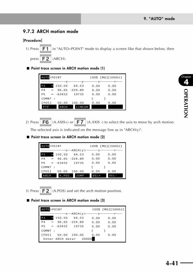
4-40 4-41
Chapter
4
OPER
ATIO
N
9. "AUTO" mode
9.7.2 ARCH motion mode
[Procedure]
1) Press in "AUTO>POINT" mode to display a screen like that shown below, then
press (ARCH).
■ Point trace screen in ARCH motion mode (1)
AUTO>POINT 100% [MG][S0H0J]
————————————x———————y———————z———————r———
P3 = 150.50 64.53
P4 = 96.65 -224.89
P5 = -63432 19735
PTP ARCH LINEAR
COMNT : [ ]
[POS] 50.00 100.00 0.00 0.00
0.00 0.00
0.00 0.00
0.00 0.00
2) Press (A.AXIS+) or (A.AXIS -) to select the axis to move by arch motion.
The selected axis is indicated on the message line as in "ARCH(y)".
■ Point trace screen in ARCH motion mode (2)
AUTO>POINT 100% [MG][S0H0J]
————————————x——ARCH(y)——————z———————r———
P3 = 150.50 64.53
P4 = 96.65 -224.89
P5 = -63432 19735
ARCH A.POS JUMP VEL+ VEL–
COMNT : [ ]
[POS] 50.00 100.00 0.00 0.00
0.00 0.00
0.00 0.00
0.00 0.00
3) Press (A.POS) and set the arch motion position.
■ Point trace screen in ARCH motion mode (3)
AUTO>POINT 100% [MG][S0H0J]
P3 = 150.50 64.53
P4 = 96.65 -224.89
P5 = -63432 19735
Enter ARCH data> 20000
COMNT : [ ]
[POS] 50.00 100.00 0.00 0.00
0.00 0.00
0.00 0.00
0.00 0.00
————————————x——ARCH(y)——————z———————r———

4-42
Chapter
4
OPER
ATIO
N
4-43
9. "AUTO" mode
n NOTE
Enter the number of pulses for the Y-axis.
4) Use the cursor (↑/↓) keys to select the point number to be checked.
5) Press to move the robot by arch motion to the specified point position. The
trace speed is one fifth of the automatic movement speed. To stop the trace, press
.
wWARNING
UPON PRESSING , THE ROBOT STARTS TO MOVE. TO AVOID DANGER, DO
NOT ENTER THE ROBOT MOVEMENT RANGE.

4-42 4-43
Chapter
4
OPER
ATIO
N
9. "AUTO" mode
9.7.3 Linear interpolation motion mode
[Procedure]
1) Press in "AUTO>POINT" mode to display a screen like that shown below, then
press (LINEAR).
■ Point trace screen in linear interpolation motion mode (1)
AUTO>POINT 100% [MG][S0H0J]
————————————x———————y———————z———————r———
P3 = 150.50 64.53
P4 = 96.65 -224.89
P5 = -63432 19735
PTP ARCH LINEAR
COMNT : [ ]
[POS] 50.00 100.00 0.00 0.00
0.00 0.00
0.00 0.00
0.00 0.00
2) Use the cursor (↑/↓) keys to select the point number to be checked.
n NOTE
Linear interpolation motion at the sub robot is not supported in controller
versions prior to Ver. 9.11.
■ Point trace screen in linear interpolation motion mode (2)
AUTO>POINT 100% [MG][S0H0J]
————————————x———————y———————z———————r———
P3 = 150.50 64.53
P4 = 96.65 -224.89
P5 = -63432 19735
LINEAR JUMP VEL+ VEL-
COMNT : [ ]
[POS] 50.00 100.00 0.00 0.00
0.00 0.00
0.00 0.00
0.00 0.00
3) Press to move the robot by linear interpolation motion to the specified point
position. The trace speed is one fifth of the automatic movement speed. To stop the
trace, press .
wWARNING
UPON PRESSING , THE ROBOT STARTS TO MOVE. TO AVOID DANGER, DO
NOT ENTER THE ROBOT MOVEMENT RANGE.
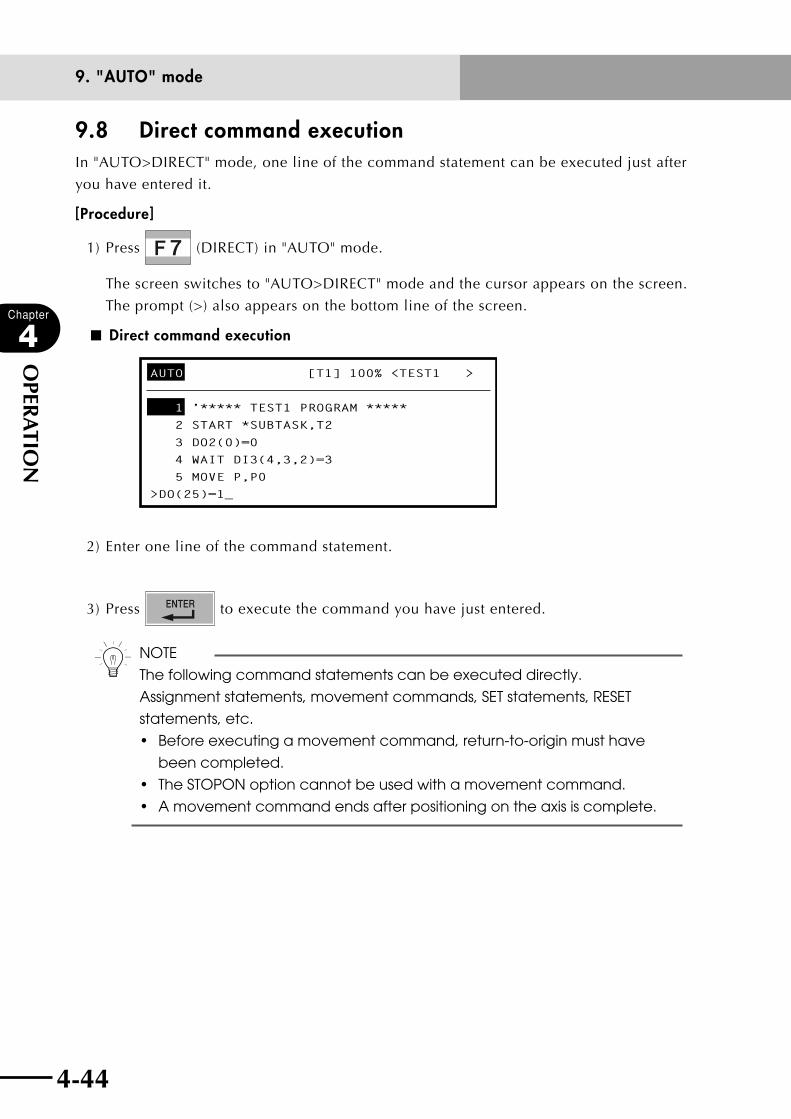
4-44
Chapter
4
OPER
ATIO
N
4-45
9. "AUTO" mode
9.8 Direct command executionIn "AUTO>DIRECT" mode, one line of the command statement can be executed just after
you have entered it.
[Procedure]
1) Press (DIRECT) in "AUTO" mode.
The screen switches to "AUTO>DIRECT" mode and the cursor appears on the screen.
The prompt (>) also appears on the bottom line of the screen.
■ Direct command execution
AUTO [T1] 100% <TEST1 >
1 ’***** TEST1 PROGRAM *****
2 START *SUBTASK,T2
3 DO2(0)=0
4 WAIT DI3(4,3,2)=3
5 MOVE P,P0
>DO(25)=1_
2) Enter one line of the command statement.
3) Press to execute the command you have just entered.
n NOTE
The following command statements can be executed directly.
Assignment statements, movement commands, SET statements, RESET
statements, etc.
• Beforeexecutingamovementcommand,return-to-originmusthave
been completed.
• TheSTOPONoptioncannotbeusedwithamovementcommand.
• Amovementcommandendsafterpositioningontheaxisiscomplete.
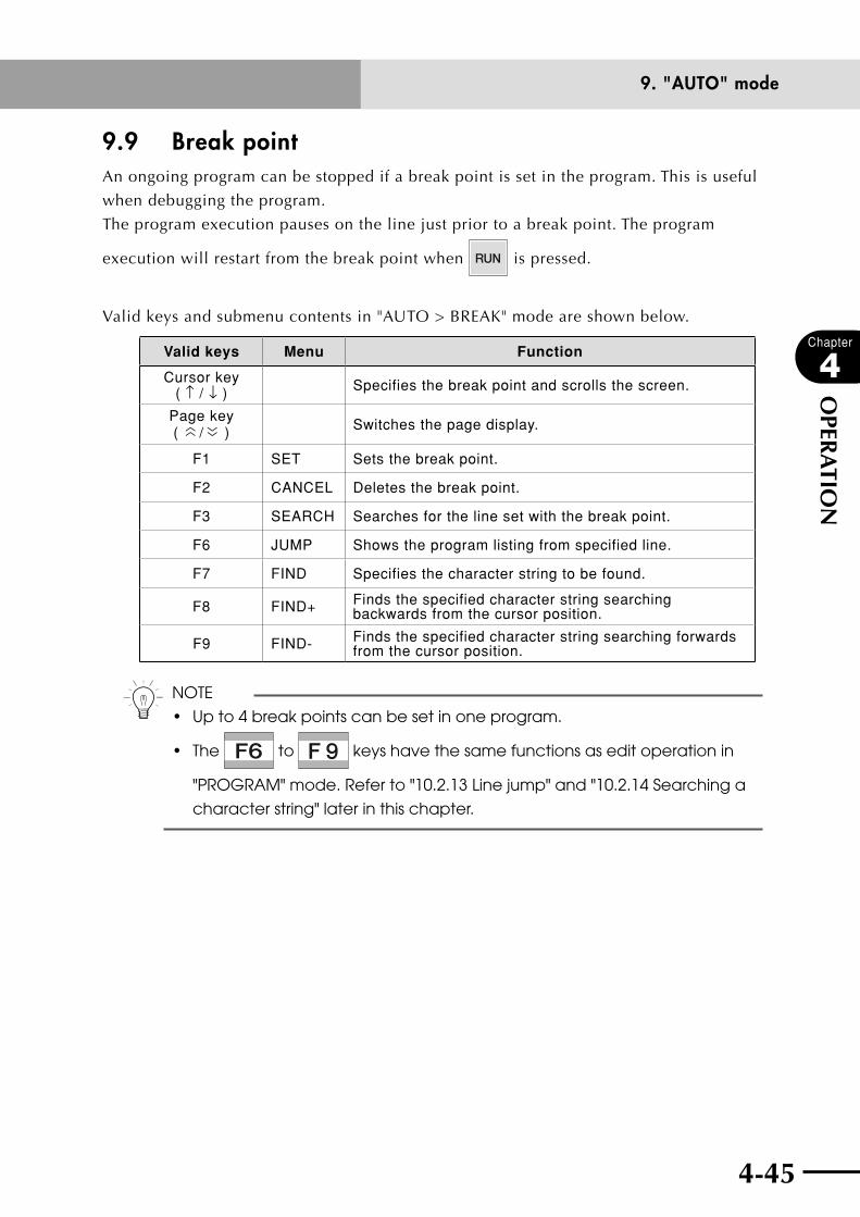
4-44 4-45
Chapter
4
OPER
ATIO
N
9. "AUTO" mode
9.9 Break pointAn ongoing program can be stopped if a break point is set in the program. This is useful
when debugging the program.
The program execution pauses on the line just prior to a break point. The program
execution will restart from the break point when is pressed.
Valid keys and submenu contents in "AUTO > BREAK" mode are shown below.
Valid keys Menu Function
Cursor key ( ↑ / ↓ ) Specifies the break point and scrolls the screen.
Page key (
〈〈 / 〈〈 ) Switches the page display.
F1 SET Sets the break point.
F2 CANCEL Deletes the break point.
F3 SEARCH Searches for the line set with the break point.
F6 JUMP Shows the program listing from specified line.
F7 FIND Specifies the character string to be found.
F8 FIND+ Finds the specified character string searching backwards from the cursor position.
F9 FIND- Finds the specified character string searching forwards from the cursor position.
n NOTE
• Upto4breakpointscanbesetinoneprogram.
• The to keys have the same functions as edit operation in
"PROGRAM" mode. Refer to "10.2.13 Line jump" and "10.2.14 Searching a
character string" later in this chapter.
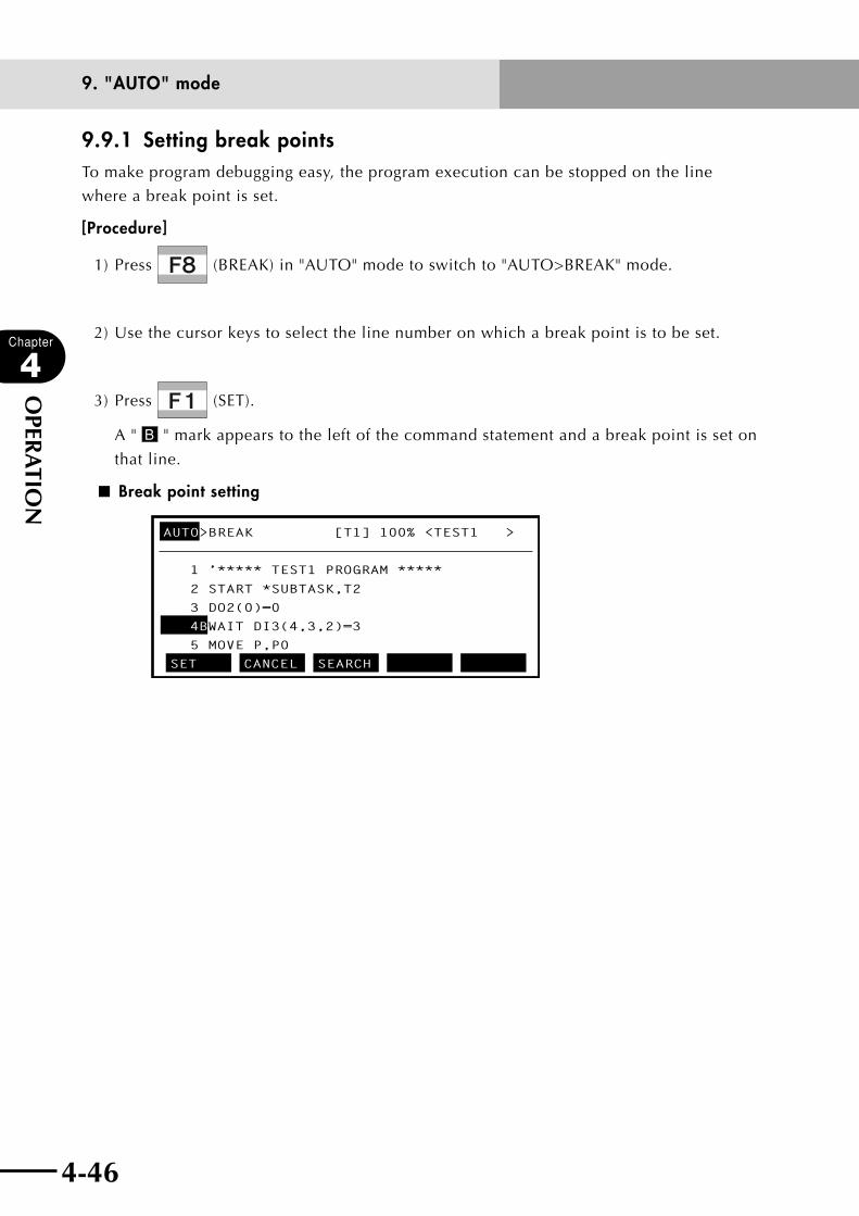
4-46
Chapter
4
OPER
ATIO
N
4-47
9. "AUTO" mode
9.9.1 Setting break pointsTo make program debugging easy, the program execution can be stopped on the line
where a break point is set.
[Procedure]
1) Press (BREAK) in "AUTO" mode to switch to "AUTO>BREAK" mode.
2) Use the cursor keys to select the line number on which a break point is to be set.
3) Press (SET).
A " B " mark appears to the left of the command statement and a break point is set on
that line.
■ Break point setting
AUTO>BREAK [T1] 100% <TEST1 >
1 ’***** TEST1 PROGRAM *****
2 START *SUBTASK,T2
3 DO2(0)=0
4BWAIT DI3(4,3,2)=3
5 MOVE P,P0
SET CANCEL SEARCH
4-46 4-47
Chapter
4
OPER
ATIO
N
9. "AUTO" mode
9.9.2 Deleting break points
Break points can be deleted. Press (SEARCH) as needed to find a break point that
was set.
[Procedure]
1) Use the cursor (↑/↓) keys to select the line number where the break point is set.
2) Press (CANCEL).
The " B " mark disappears and the break point is canceled.
3) To find the line number on which another break point was set, press (SEARCH).
This function makes it easier to find a break point that you want to delete.
n NOTE
• Upto4breakpointscanbesetinoneprogram.These4breakpoints
cannot set in different programs. However, when there is "COMMON"
program, 4 break points can be set including the main program. (For
more information on the COMMON program, refer to the programming
manual.)
• Iftheprogramiscompiledoredited,allthebreakpointsaredeleted.
• BreakpointsareignoredduringexecutionofSTEPorNEXT.However,
break points set in sub-routines are enabled when executing NEXT.

4-48
Chapter
4
OPER
ATIO
N
4-49
9. "AUTO" mode
9.10 Executing a step
wWARNINGTHE ROBOT MAY BEGIN TO MOVE WHEN STEP IS EXECUTED. TO AVOID DANGER, DO NOT ENTER THE ROBOT MOVEMENT RANGE.
[Procedure]
1) Press (STEP) in "AUTO" mode.
2) Each time this key is pressed, the command statement of the highlighted line number
is executed.
After execution, the pointer moves to the next line.
If the command statement is a sub-routine or sub-procedure, its top line is executed.
■ STEP execution
AUTO [T1] 100% <TEST1 >
1 ’***** TEST1 PROGRAM *****
2 START *SUBTASK,T2
3 DO2(0)=0
4 WAIT DI3(4,3,2)=3
5 MOVE P,P0
STEP SKIP NEXT
>
n NOTE
During STEP, SKIP and NEXT execution, the message "Running" is displayed on
the screen.
After execution is complete, the pointer moves to the line number of the
next command statement.
9.11 Skipping a step
[Procedure]
1) Press (SKIP) in "AUTO" mode.
2) The program moves (skips) to the next line each time this key is pressed without
executing the command statement of the line number where the pointer is displayed.
4-48 4-49
Chapter
4
OPER
ATIO
N
9. "AUTO" mode
9.12 Executing the next step
wWARNINGTHE ROBOT MAY BEGIN TO MOVE WHEN NEXT IS EXECUTED. TO AVOID DANGER, DO NOT ENTER THE ROBOT MOVEMENT RANGE.
[Procedure]
1) Press (NEXT) in "AUTO" mode.
2) Each time this key is pressed, the command statement of the highlighted line number
is executed. After execution, the pointer moves to the next line.
If the command statement is a sub-routine or sub-procedure, it is executed at once.
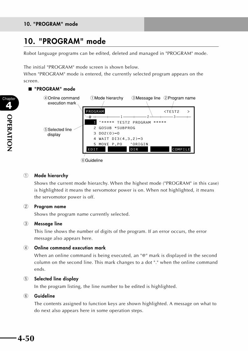
4-50
Chapter
4
OPER
ATIO
N
10. "PROGRAM" mode
4-51
10. "PROGRAM" modeRobot language programs can be edited, deleted and managed in "PROGRAM" mode.
The initial "PROGRAM" mode screen is shown below.
When "PROGRAM" mode is entered, the currently selected program appears on the
screen.
■ "PROGRAM" mode
qMode hierarchy wProgram nameeMessage linerOnline command execution mark
tSelected line display
yGuideline
PROGRAM <TEST2 >
1 '***** TEST2 PROGRAM *****
2 GOSUB *SUBPROG
3 DO2(0)=0
4 WAIT DI3(4,3,2)=3
5 MOVE P,P0 ‘ORIGIN
EDIT DIR COMPILE
— @ ————————————————————————————————————————1 2 3
q Mode hierarchy
Shows the current mode hierarchy. When the highest mode ("PROGRAM" in this case)
is highlighted it means the servomotor power is on. When not highlighted, it means
the servomotor power is off.
w Program name
Shows the program name currently selected.
e Message line
This line shows the number of digits of the program. If an error occurs, the error
message also appears here.
r Online command execution mark
When an online command is being executed, an "@" mark is displayed in the second
column on the second line. This mark changes to a dot "." when the online command
ends.
t Selected line display
In the program listing, the line number to be edited is highlighted.
y Guideline
The contents assigned to function keys are shown highlighted. A message on what to
do next also appears here in some operation steps.
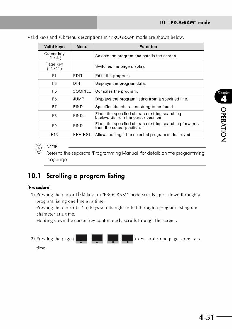
4-50 4-51
Chapter
4
OPER
ATIO
N
10. "PROGRAM" mode
Valid keys and submenu descriptions in "PROGRAM" mode are shown below.
Valid keys Menu Function
Cursor key ( ↑ / ↓ ) Selects the program and scrolls the screen.
Page key (
〈〈 / 〈〈 ) Switches the page display.
F1 EDIT Edits the program.
F3 DIR Displays the program data.
F5 COMPILE Compiles the program.
F6 JUMP Displays the program listing from a specified line.
F7 FIND Specifies the character string to be found.
F8 FIND+ Finds the specified character string searching backwards from the cursor position.
F9 FIND- Finds the specified character string searching forwards from the cursor position.
F13 ERR.RST Allows editing if the selected program is destroyed.
n NOTE
Refer to the separate "Programming Manual" for details on the programming
language.
10.1 Scrolling a program listing
[Procedure]
1) Pressing the cursor (↑/↓) keys in "PROGRAM" mode scrolls up or down through a
program listing one line at a time.
Pressing the cursor (←/→) keys scrolls right or left through a program listing one
character at a time.
Holding down the cursor key continuously scrolls through the screen.
2) Pressing the page ( , , , ) key scrolls one page screen at a
time.

4-52
Chapter
4
OPER
ATIO
N
10. "PROGRAM" mode
4-53
10.2 Program editing
[Procedure]
1) Press (EDIT) in "PROGRAM" mode.
A cursor appears on the top line of a program listing as shown below, allowing
program editing.
2) Use the cursor keys to move the cursor to the position to be edited and enter a
program command with the RPB.
A maximum of 75 characters can be entered on one line.
n NOTE
Program editing is finished when any of , up/down cursor (↑/↓)
keys, page up/down ( / ) keys, or is pressed during
program editing.
A maximum of 9999 lines can be written in one program as long as the
program size is within about 98 Kbytes.
■ "PROGRAM>EDIT" mode
PROGRAM>EDIT <TEST2 >
1 ’***** TEST2 PROGRAM *****
2 GOSUB *SUBPROG
3 DO2(0)=0
4 WAIT DI3(4,3,2)=3
5 MOVE P,P0 ’ORIGIN
SELECT COPY CUT PASTE BS
———————————————————————————————————————————1 2 3
Pressing finishes the program input for one line and moves the cursor to
the beginning of the next line.
3) When program editing is complete, press .
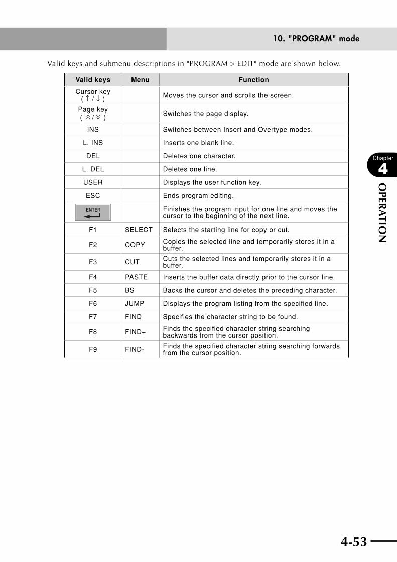
4-52 4-53
Chapter
4
OPER
ATIO
N
10. "PROGRAM" mode
Valid keys and submenu descriptions in "PROGRAM > EDIT" mode are shown below.
Valid keys Menu Function
Cursor key ( ↑ / ↓ ) Moves the cursor and scrolls the screen.
Page key (
〈〈 / 〈〈 ) Switches the page display.
INS Switches between Insert and Overtype modes.
L. INS Inserts one blank line.
DEL Deletes one character.
L. DEL Deletes one line.
USER Displays the user function key.
ESC Ends program editing.
Finishes the program input for one line and moves the cursor to the beginning of the next line.
F1 SELECT Selects the starting line for copy or cut.
F2 COPY Copies the selected line and temporarily stores it in a buffer.
F3 CUT Cuts the selected lines and temporarily stores it in a buffer.
F4 PASTE Inserts the buffer data directly prior to the cursor line.
F5 BS Backs the cursor and deletes the preceding character.
F6 JUMP Displays the program listing from the specified line.
F7 FIND Specifies the character string to be found.
F8 FIND+ Finds the specified character string searching backwards from the cursor position.
F9 FIND- Finds the specified character string searching forwards from the cursor position.
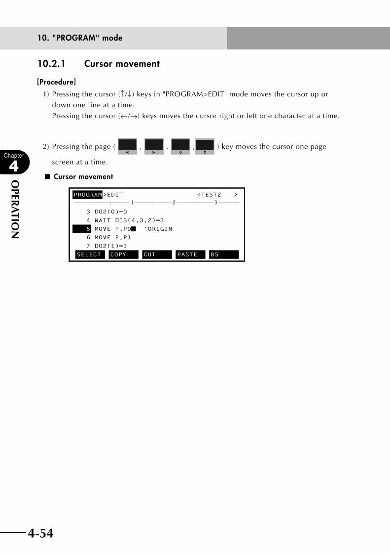
4-54
Chapter
4
OPER
ATIO
N
10. "PROGRAM" mode
4-55
10.2.1 Cursor movement
[Procedure]
1) Pressing the cursor (↑/↓) keys in "PROGRAM>EDIT" mode moves the cursor up or
down one line at a time.
Pressing the cursor (←/→) keys moves the cursor right or left one character at a time.
2) Pressing the page ( , , , ) key moves the cursor one page
screen at a time.
■ Cursor movement
PROGRAM>EDIT <TEST2 >
3 DO2(0)=0
4 WAIT DI3(4,3,2)=3
5 MOVE P,P0_ ’ORIGIN
6 MOVE P,P1
7 DO2(1)=1
SELECT COPY CUT PASTE BS
———————————————————————————————————————————1 2 3

4-54 4-55
Chapter
4
OPER
ATIO
N
10. "PROGRAM" mode
10.2.2 Insert/Overwrite mode switching
[Procedure]
1) Press in "PROGRAM > EDIT" mode.
The cursor changes to underline ( _ ) form, and the screen switches to Insert mode.
In Insert mode, the input character is inserted just previous to the cursor position.
■ Insert mode
PROGRAM>EDIT <TEST2 >
3 DO2(0)=0
4 WAIT DI3(4,3,2)=3
5 MOVE P,P06 _ ’ORIGIN
7 MOVE P,P1
SELECT COPY CUT PASTE BS
———————————————————————————————————————————1 2 3
2) Press again.
The cursor changes back to a thick line ( ■), and the screen returns to Overwrite
mode.
In Overwrite mode, the input character replaces the character at the cursor position.
■ Overwrite mode
PROGRAM>EDIT <TEST2 >
3 DO2(0)=0
4 WAIT DI3(4,3,2)=3
5 MOVE P,P0
’ORIGIN6
MOVE P,P17 SELECT COPY CUT PASTE BS
———————————————————————————————————————————1 2 3
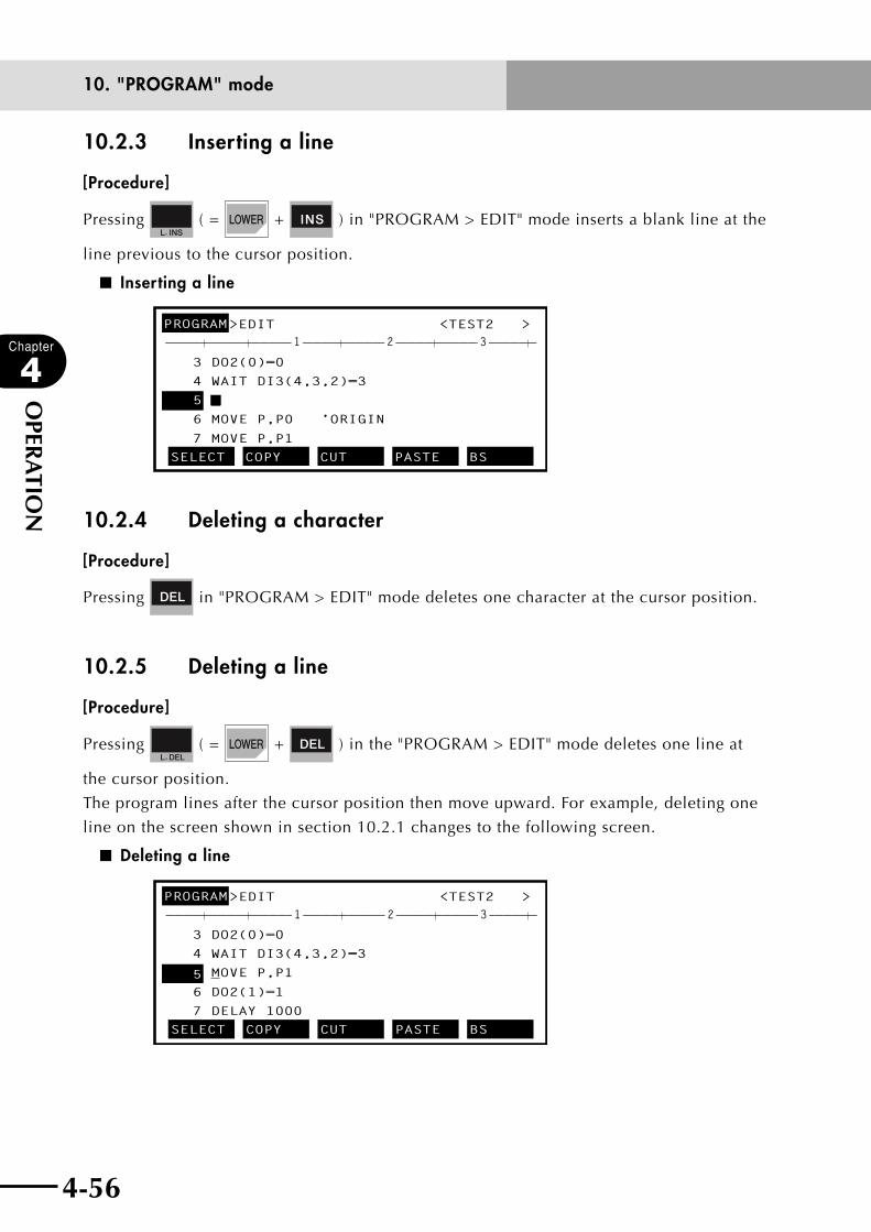
4-56
Chapter
4
OPER
ATIO
N
10. "PROGRAM" mode
4-57
10.2.3 Inserting a line
[Procedure]
Pressing ( = + ) in "PROGRAM > EDIT" mode inserts a blank line at the
line previous to the cursor position.
■ Inserting a line
PROGRAM>EDIT <TEST2 >
3 DO2(0)=0
4 WAIT DI3(4,3,2)=3
5 _
6 MOVE P,P0 ’ORIGIN
7 MOVE P,P1
SELECT COPY CUT PASTE BS
———————————————————————————————————————————1 2 3
10.2.4 Deleting a character
[Procedure]
Pressing in "PROGRAM > EDIT" mode deletes one character at the cursor position.
10.2.5 Deleting a line
[Procedure]
Pressing ( = + ) in the "PROGRAM > EDIT" mode deletes one line at
the cursor position.
The program lines after the cursor position then move upward. For example, deleting one
line on the screen shown in section 10.2.1 changes to the following screen.
■ Deleting a line
PROGRAM>EDIT <TEST2 >
3 DO2(0)=0
4 WAIT DI3(4,3,2)=3
5 MOVE P,P1
6 DO2(1)=1
7 DELAY 1000
SELECT COPY CUT PASTE BS
———————————————————————————————————————————1 2 3

4-56 4-57
Chapter
4
OPER
ATIO
N
10. "PROGRAM" mode
10.2.6 User function key displayUser function keys make it easier to enter programs.
n NOTE
When using this function, it is necessary to make a program named
"FUNCTION" and then write command statements for registering functions.
For information on how to register the function keys, refer to "10.3.9 Creating
a sample program automatically" and "10.6 Registering user function keys"
later in this chapter.
[Procedure]
1) Press in "PROGRAM > EDIT" mode to display the character strings on the
guideline, which are preassigned to function keys to .
Each character string is displayed in up to 7 characters from the beginning.
2) Press the function key matching the character string you want to enter.
For example, when (GOTO *) is pressed on the following screen, the character
string for "GOTO *" is entered at the cursor position.
■ User function keys
PROGRAM>EDIT <TEST2 >
1 ’***** TEST2 PROGRAM *****
2 GOTO *_
3 DO2(0)=0
4 WAIT DI3(4,3,2)=3
5 MOVE P,P0 ’ORIGIN
MOVE P, GOTO * DELAY FOR ?=? SEND ?
———————————————————————————————————————————1 2 3

4-58
Chapter
4
OPER
ATIO
N
10. "PROGRAM" mode
4-59
10.2.7 Quitting program editing
Press to quit program editing in "PROGRAM>EDIT" mode.
10.2.8 Specifying the copy/cut lines
[Procedure]
1) In "PROGRAM>EDIT" mode, move the cursor to the line you want to copy or cut.
2) Press (SELECT) to select the line.
3) Use the cursor (↓) keys to specify the copy/cut range.
A " C " mark appears on each line which was specified.
Press if you want to cancel this operation.
■ Specifying the copy/cut lines
PROGRAM>EDIT <TEST2 >
1C’***** TEST2 PROGRAM *****
2C’
3C DO2(0)=0
4 WAIT DI3(4,3,2)=3
5 MOVE P,P0 ’ORIGINSELECT COPY CUT PASTE BS
———————————————————————————————————————————1 2 3
n NOTE
When selecting a line range, the maximum number of characters is 200. If
the number of characters exceeds 200, the selected line range must be
reduced. The number of characters on one line is the count from the top to
the last characters (excluding blanks) plus 1.
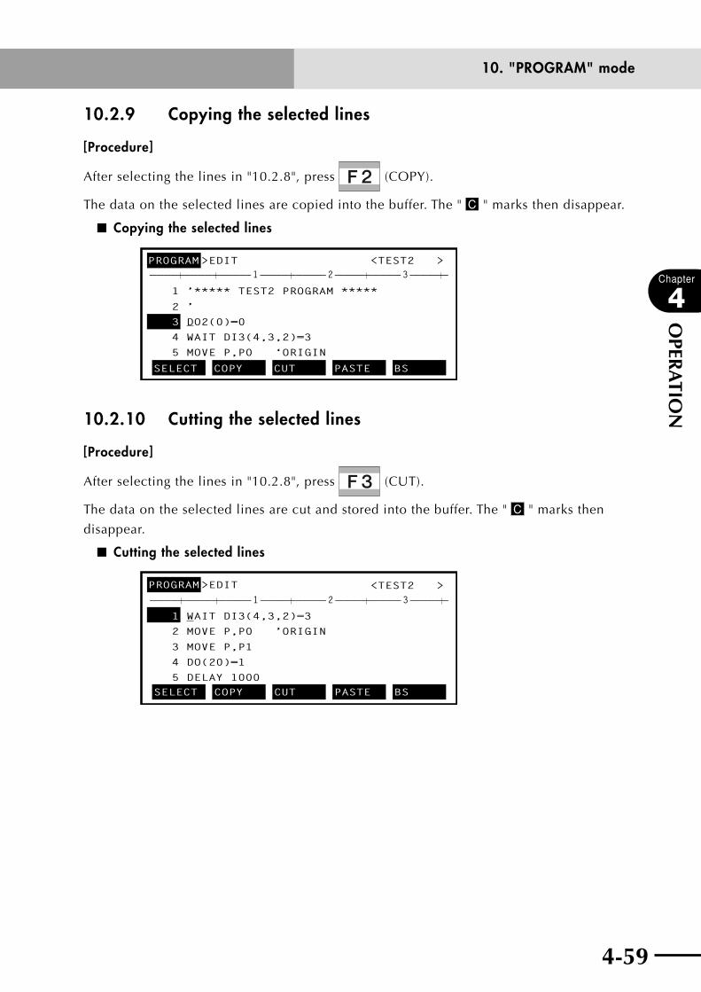
4-58 4-59
Chapter
4
OPER
ATIO
N
10. "PROGRAM" mode
10.2.9 Copying the selected lines
[Procedure]
After selecting the lines in "10.2.8", press (COPY).
The data on the selected lines are copied into the buffer. The " C " marks then disappear.
■ Copying the selected lines
PROGRAM>EDIT <TEST2 >
1 ’***** TEST2 PROGRAM *****
2 ’
3 DO2(0)=0
4 WAIT DI3(4,3,2)=3
5 MOVE P,P0 ‘ORIGIN
SELECT COPY CUT PASTE BS
———————————————————————————————————————————1 2 3
10.2.10 Cutting the selected lines
[Procedure]
After selecting the lines in "10.2.8", press (CUT).
The data on the selected lines are cut and stored into the buffer. The " C " marks then
disappear.
■ Cutting the selected lines
PROGRAM>EDIT <TEST2 >
1 WAIT DI3(4,3,2)=3
2 MOVE P,P0 ’ORIGIN
3 MOVE P,P1
4 DO(20)=1
5 DELAY 1000SELECT COPY CUT PASTE BS
———————————————————————————————————————————1 2 3
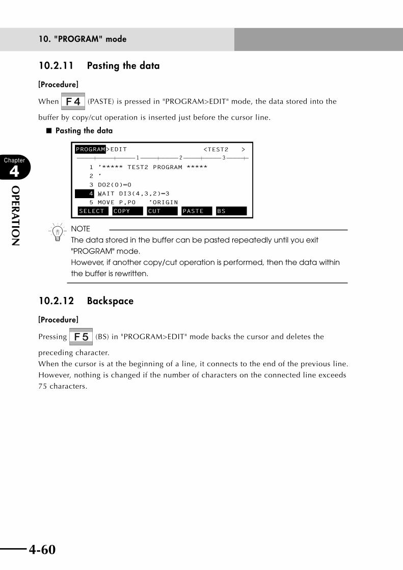
4-60
Chapter
4
OPER
ATIO
N
10. "PROGRAM" mode
4-61
10.2.11 Pasting the data
[Procedure]
When (PASTE) is pressed in "PROGRAM>EDIT" mode, the data stored into the
buffer by copy/cut operation is inserted just before the cursor line.
■ Pasting the data
PROGRAM>EDIT <TEST2 >
1 ’***** TEST2 PROGRAM *****
2 ’
3 DO2(0)=0
4 WAIT DI3(4,3,2)=3
5 MOVE P,P0 ’ORIGIN
SELECT COPY CUT PASTE BS
———————————————————————————————————————————1 2 3
n NOTE
The data stored in the buffer can be pasted repeatedly until you exit
"PROGRAM" mode.
However, if another copy/cut operation is performed, then the data within
the buffer is rewritten.
10.2.12 Backspace
[Procedure]
Pressing (BS) in "PROGRAM>EDIT" mode backs the cursor and deletes the
preceding character.
When the cursor is at the beginning of a line, it connects to the end of the previous line.
However, nothing is changed if the number of characters on the connected line exceeds
75 characters.

4-60 4-61
Chapter
4
OPER
ATIO
N
10. "PROGRAM" mode
10.2.13 Line jump
[Procedure]
1) In "PROGRAM>EDIT" mode, press (JUMP) to enter "PROGRAM>EDIT>JUMP"
mode.
The message "Enter line no. > " appears on the guideline.
■ Line jump
PROGRAM>EDIT <TEST2 >
1 ’***** TEST2 PROGRAM *****
2 GOTO *_’3 DO2(0)=0
4 WAIT DI3(4,3,2)=3
5 MOVE P,P0 ’ORIGIN
Enter line no. >45_
———————————————————————————————————————————1 2 3
2) Enter the line number to jump to and press .
The program is then displayed from the specified line.
■ Performing line jump
PROGRAM>EDIT <TEST2 >
45 RESET DO3(4)
46 DELAY 1000
47 A=4
48 GOTO *T4
49 *T5:
SELECT COPY CUT PASTE BS
———————————————————————————————————————————1 2 3
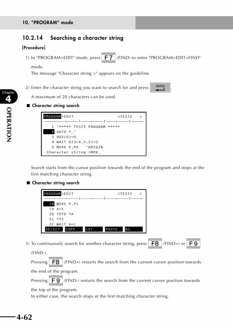
4-62
Chapter
4
OPER
ATIO
N
10. "PROGRAM" mode
4-63
10.2.14 Searching a character string
[Procedure]
1) In "PROGRAM>EDIT" mode, press (FIND) to enter "PROGRAM>EDIT>FIND"
mode.
The message "Character string >" appears on the guideline.
2) Enter the character string you want to search for and press .
A maximum of 20 characters can be used.
■ Character string search
PROGRAM>EDIT <TEST2 >
1 ’***** TEST2 PROGRAM *****
2 GOTO *_’
3 DO2(0)=0
4 WAIT DI3(4,3,2)=3
5 MOVE P,P0 ’ORIGIN
Character string >MOV_
———————————————————————————————————————————1 2 3
Search starts from the cursor position towards the end of the program and stops at the
first matching character string.
■ Character string search
PROGRAM>EDIT <TEST2 >
18 MOVE P,P1
19 A=1
20 TOTO *A
21 *T2
22 WAIT A=1
SELECT COPY CUT PASTE BS
———————————————————————————————————————————1 2 3
3) To continuously search for another character string, press (FIND+) or
(FIND-).
Pressing (FIND+) restarts the search from the current cursor position towards
the end of the program.
Pressing (FIND-) restarts the search from the current cursor position towards
the top of the program.
In either case, the search stops at the first matching character string.

4-62 4-63
Chapter
4
OPER
ATIO
N
10. "PROGRAM" mode
10.3 Directory
When (DIR) is pressed in "PROGRAM" mode, information on each program appears
as shown below.
n NOTE
A maximum of 100 programs can be stored.
■ Program information (1)
PROGRAM>DIR <TEST1 >
No.
1 TEST1 55 952 RW
2 *TEST2 50 907 RW
3 PARTS100 38 843 RW
4 TEST100 100 1968 RW
NEW INFO
Name Line Byte RW/RO
Pressing on the above screen displays the "DATE" and "TIME" data.
(Press to return to the previous display.)
n NOTE
The date and time are updated when the program is created or edited.
■ Program data (2)
PROGRAM>DIR <TEST1 >
No.
1 TEST1 06/06/01 10:18
2 *TEST2 06/06/01 17:20
3 PARTS100 06/06/01 13:19
4 TEST100 06/06/01 08:35
NEW INFO
Name Date Time

4-64
Chapter
4
OPER
ATIO
N
10. "PROGRAM" mode
4-65
Contents of each item are shown below.
Item Description
No.Indicates the serial number of the program. The number of the program which is currently selected is highlighted (reversed background).
Name
Indicates the program name. The " * " mark (reversed background) shows this program is compiled and the object program exists. The " s " mark (reverse background) shows an object exists in the sequence program.
Line Shows the number of lines in the program.
Byte Shows how many bytes of memory the program uses.
RW/ROIndicates the program attribute. RW : Reading or writing enabled. RO : Reading only enabled; writing inhibited.
Date Shows the date when the program was made or edited.
Time Shows the time when the program was made or edited.
Valid keys and submenu descriptions in "PROGRAM >DIR" mode are shown below.
Valid keys Menu Function
Cursor key ( ↑ / ↓ ) Selects the program or scrolls the screen vertically.
Cursor key (← / →)
Switches between the program information display and the date/time display.
Page key (
〈〈 / 〈〈 ) Switches to other screens.
F1 NEW Registers a new program name.
F5 INFO Shows the number of bytes used for the entire program.
F6 COPY Copies the program.
F7 ERASE Erases the program.
F8 RENAME Renames the program.
F10 ATTRBT Changes the program attribute.
F11 OBJECT Shows the object program information.
F15 EXAMPLE Automatically creates the program name "FUNCTION".

4-64 4-65
Chapter
4
OPER
ATIO
N
10. "PROGRAM" mode
10.3.1 Cursor movement
[Procedure]To select the program, use the cursor (↑/↓) keys in "PROGRAM>DIR" mode.
The pointer cursor moves to the selected program number.
The program name is displayed at the right end on the system line (1st line).
10.3.2 Registering a new program nameWhen creating a new program, you must first register the program name.
[Procedure]
1) In "PROGRAM>DIR" mode, press (NEW) to enter "PROGRAM>DIR>NEW" mode.
The message "Enter program name > " appears on the guideline.
2) Use to , to or to enter a program name.
A maximum of 8 characters can be used. (Press if you want to cancel the data
input.)
n NOTEProgram names can be up to 8 characters consisting of a combination of alphanumeric characters (0 to 9, A to Z) and underscores ( _ ).
■ Registering a new program
PROGRAM>DIR <TEST1 >
No. RW/RO
1 TEST1 55 952 RW
2 *TEST2 50 907 RW
3 PARTS100 38 843 RW
4 TEST100 100 1968 RW
Enter program name >ABC123_
Name Line Byte
3) Press to register the program name.
n NOTEThe following program names have special meanings."FUNCTION""SEQUENCE""_SELECT""COMMON"(Refer to "Programming Manual" for these programs.)

4-66
Chapter
4
OPER
ATIO
N
10. "PROGRAM" mode
4-67
10.3.3 Directory information display
[Procedure]
In "PROGRAM>DIR" mode, press (INFO) to enter "PROGRAM>DIR>INFO" mode.
The following information on the selected program appears.
■ Program information
PROGRAM>DIR>INFO <TEST1 >
Source(use/sum) = 1316/364580 bytes
Object(use/sum) = 528/ 98304 bytes
Sequence(use/sum) = 0/ 4096 bytes
Number of program = 5
Number of points = 124
Item Description
Source (use/sum) Displays a count of used bytes and bytes available for source program and point data.
Object (use/sum) Displays a count of used bytes and bytes available for object program.
Sequence (use/sum)Displays a count of used bytes and bytes available for sequence object program. (8 bytes are used for one circuit of sequence program.)
Number of program Displays the number of programs.
Number of points Displays the number of points that have been set. (28 bytes are used for one point.)
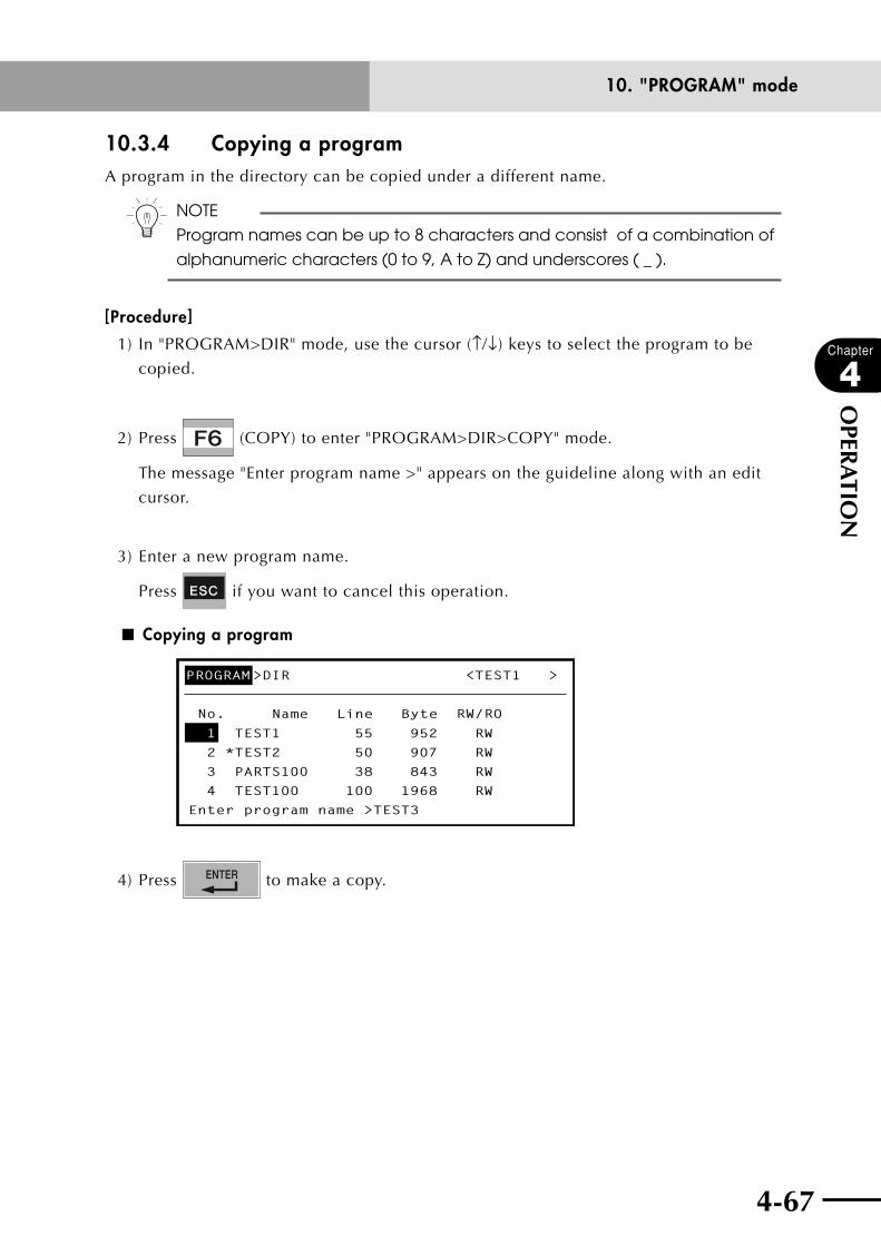
4-66 4-67
Chapter
4
OPER
ATIO
N
10. "PROGRAM" mode
10.3.4 Copying a programA program in the directory can be copied under a different name.
n NOTE
Program names can be up to 8 characters and consist of a combination of
alphanumeric characters (0 to 9, A to Z) and underscores ( _ ).
[Procedure]
1) In "PROGRAM>DIR" mode, use the cursor (↑/↓) keys to select the program to be
copied.
2) Press (COPY) to enter "PROGRAM>DIR>COPY" mode.
The message "Enter program name >" appears on the guideline along with an edit
cursor.
3) Enter a new program name.
Press if you want to cancel this operation.
■ Copying a program
PROGRAM>DIR <TEST1 >
No. RW/RO
1 TEST1 55 952 RW
2 *TEST2 50 907 RW
3 PARTS100 38 843 RW
4 TEST100 100 1968 RW
Enter program name >TEST3
Name Line Byte
4) Press to make a copy.

4-68
Chapter
4
OPER
ATIO
N
10. "PROGRAM" mode
4-69
10.3.5 Erasing a programUnnecessary programs in the directory can be erased.
cCAUTION• programswithan"ro(readonly)"attributecannotbeerased.when
these programs must be erased, change the attribute.• tochangetheprogramattribute,referto"10.3.7changingtheprogram
attribute".
[Procedure]
1) In "PROGRAM>DIR" mode, use the cursor (↑/↓) keys to select the program to be
erased.
2) Press (ERASE) to enter "PROGRAM>DIR>ERASE" mode.
A confirmation message appears on the guideline.
■ Erasing a program
PROGRAM>DIR>ERASE <TEST1 >
No. RW/RO
1 TEST1 55 952 RW
2 *TEST2 50 907 RW
3 PARTS100 38 843 RW
4 TEST100 100 1968 RW
Erase program OK? YES NO
Name Line Byte
3) Press (YES) to erase the selected program.
Press (NO) if you want to cancel erasure.
After the program is erased, the lower program names move upward.
■ After erasing a program
PROGRAM>DIR <TEST2 >
No. RW/RO
1 *TEST2 50 907 RW
2 PARTS100 38 843 RW
3 TEST100 100 1968 RW
4 TEST200 80 1525 RW
NEW INFO
Name Line Byte

4-68 4-69
Chapter
4
OPER
ATIO
N
10. "PROGRAM" mode
10.3.6 Renaming a programTo change the names of programs in the directory, proceed as follows.
[Procedure]
1) In "PROGRAM>DIR" mode, use the cursor (↑/↓) keys to select the program to be
renamed.
2) Press (RENAME) to enter "PROGRAM>DIR>RENAME" mode.
The message "Enter program name" appears on the guideline along with the original
program name.
■ Renaming a program
PROGRAM>DIR <TEST1 >
No. RW/RO
1 TEST1
*TEST2
55 952 RW
2
PARTS100
50 907 RW
3
TEST100
38 843 RW
4 100 31968 RW
Enter program name >TEST_
Name Line Byte
3) Enter a new program name.
Press if you want to cancel this operation.
4) Press to rename the program.
n NOTE
Program names can be up to 8 characters and consist of a combination of
alphanumeric characters (0 to 9, A to Z) and underscores ( _ ).
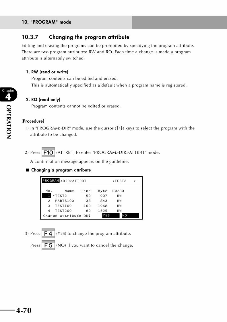
4-70
Chapter
4
OPER
ATIO
N
10. "PROGRAM" mode
4-71
10.3.7 Changing the program attributeEditing and erasing the programs can be prohibited by specifying the program attribute.
There are two program attributes: RW and RO. Each time a change is made a program
attribute is alternately switched.
1. RW (read or write)Program contents can be edited and erased.
This is automatically specified as a default when a program name is registered.
2. RO (read only)Program contents cannot be edited or erased.
[Procedure]
1) In "PROGRAM>DIR" mode, use the cursor (↑/↓) keys to select the program with the
attribute to be changed.
2) Press (ATTRBT) to enter "PROGRAM>DIR>ATTRBT" mode.
A confirmation message appears on the guideline.
■ Changing a program attribute
>DIR>ATTRBT <TEST2 >
No. RW/RO
1 *TEST2 50 907 RW
2 PARTS100 38 843 RW
3 TEST100 100 1968 RW
4 TEST200 80 1525 RW
Change attribute OK? YES NO
Name Line Byte
PROGRAM
3) Press (YES) to change the program attribute.
Press (NO) if you want to cancel the change.

4-70 4-71
Chapter
4
OPER
ATIO
N
10. "PROGRAM" mode
10.3.8 Displaying object program informationTo display information on an executable object program, proceed as follows.
[Procedure]
1) Press (OBJECT) to enter "PROGRAM>DIR>OBJECT" mode.
2) Object information appears as shown below.
■ Object program information
PROGRAM>DIR>OBJECT <TEST2 >
No. RW/RO
1 TEST2 55 750 RO2 COMMON 20 374 RO3 SEQUENCE 40 320 RO
Name Line Byte
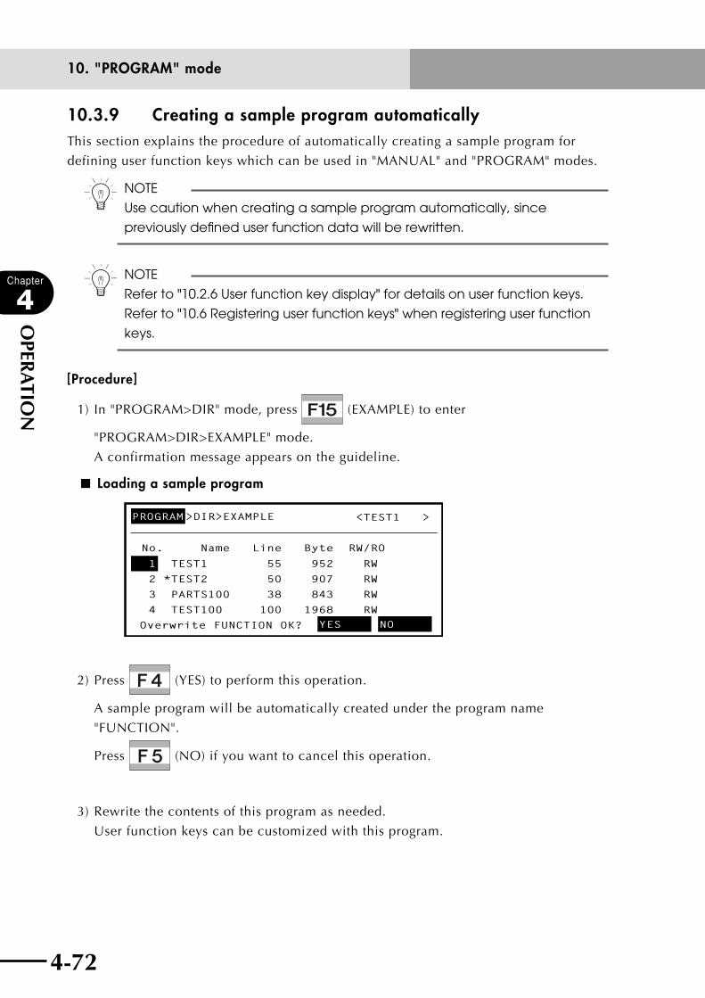
4-72
Chapter
4
OPER
ATIO
N
10. "PROGRAM" mode
4-73
10.3.9 Creating a sample program automaticallyThis section explains the procedure of automatically creating a sample program for
defining user function keys which can be used in "MANUAL" and "PROGRAM" modes.
n NOTE
Use caution when creating a sample program automatically, since
previously defined user function data will be rewritten.
n NOTE
Refer to "10.2.6 User function key display" for details on user function keys.
Refer to "10.6 Registering user function keys" when registering user function
keys.
[Procedure]
1) In "PROGRAM>DIR" mode, press (EXAMPLE) to enter
"PROGRAM>DIR>EXAMPLE" mode.
A confirmation message appears on the guideline.
■ Loading a sample program
PROGRAM>DIR>EXAMPLE <TEST1 >
No. RW/RO
1 TEST1 55 952 RW
2 *TEST2 50 907 RW
3 PARTS100 38 843 RW
4 TEST100 100 1968 RW
Overwrite FUNCTION OK? YES NO
Name Line Byte
2) Press (YES) to perform this operation.
A sample program will be automatically created under the program name
"FUNCTION".
Press (NO) if you want to cancel this operation.
3) Rewrite the contents of this program as needed.
User function keys can be customized with this program.
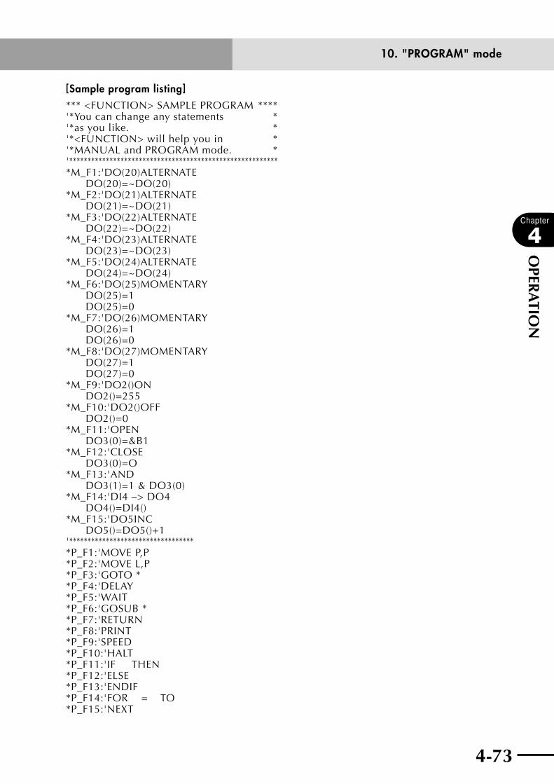
4-72 4-73
Chapter
4
OPER
ATIO
N
10. "PROGRAM" mode
[Sample program listing]*** <FUNCTION> SAMPLE PROGRAM ****'*You can change any statements *'*as you like. *'*<FUNCTION> will help you in *'*MANUAL and PROGRAM mode. *'**********************************************************M_F1:'DO(20)ALTERNATE DO(20)=~DO(20)*M_F2:'DO(21)ALTERNATE DO(21)=~DO(21)*M_F3:'DO(22)ALTERNATE DO(22)=~DO(22)*M_F4:'DO(23)ALTERNATE DO(23)=~DO(23)*M_F5:'DO(24)ALTERNATE DO(24)=~DO(24)*M_F6:'DO(25)MOMENTARY DO(25)=1 DO(25)=0*M_F7:'DO(26)MOMENTARY DO(26)=1 DO(26)=0*M_F8:'DO(27)MOMENTARY DO(27)=1 DO(27)=0*M_F9:'DO2()ON DO2()=255*M_F10:'DO2()OFF DO2()=0*M_F11:'OPEN DO3(0)=&B1*M_F12:'CLOSE DO3(0)=O*M_F13:'AND DO3(1)=1 & DO3(0)*M_F14:'DI4 –> DO4 DO4()=DI4()*M_F15:'DO5INC DO5()=DO5()+1'***********************************P_F1:'MOVE P,P*P_F2:'MOVE L,P*P_F3:'GOTO **P_F4:'DELAY *P_F5:'WAIT *P_F6:'GOSUB * *P_F7:'RETURN*P_F8:'PRINT*P_F9:'SPEED*P_F10:'HALT*P_F11:'IF THEN*P_F12:'ELSE*P_F13:'ENDIF*P_F14:'FOR = TO*P_F15:'NEXT
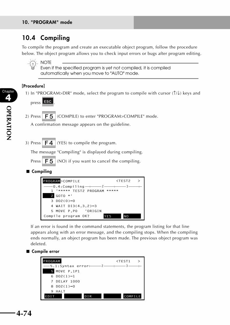
4-74
Chapter
4
OPER
ATIO
N
10. "PROGRAM" mode
4-75
10.4 CompilingTo compile the program and create an executable object program, follow the procedure
below. The object program allows you to check input errors or bugs after program editing.
n NOTEEven if the specified program is yet not compiled, it is compiled automatically when you move to "AUTO" mode.
[Procedure]
1) In "PROGRAM>DIR" mode, select the program to compile with cursor (↑/↓) keys and
press .
2) Press (COMPILE) to enter "PROGRAM>COMPILE" mode.
A confirmation message appears on the guideline.
3) Press (YES) to compile the program.
The message "Compiling" is displayed during compiling.
Press (NO) if you want to cancel the compiling.
■ Compiling
PROGRAM>COMPILE <TEST2 >
1 ’***** TEST2 PROGRAM *****
2 GOTO *’
3 DO2(0)=0
4 WAIT DI3(4,3,2)=3
5 MOVE P,P0 ’ORIGIN
Compile program OK? YES NO
———————————————————————————————————————————2 30.4:Compiling
If an error is found in the command statements, the program listing for that line appears along with an error message, and the compiling stops. When the compiling ends normally, an object program has been made. The previous object program was deleted.
■ Compile error
PROGRAM <TEST1 >
5 MOVE P,1P1
6 DO2(1)=1
7 DELAY 1000
8 DO2(1)=0
9 HALT
EDIT DIR COMPILE
———————————————————————————————————————————2 35.1:Syntax error

4-74 4-75
Chapter
4
OPER
ATIO
N
10. "PROGRAM" mode
10.5 Line jump and character string search
The (JUMP), (FIND), (FIND+) and (FIND-) keys can be used
in the same way as in "PROGRAM>EDIT" mode.
Refer to "10.2.13 Line jump" and "10.2.14 Searching a character string" earlier in this
chapter.)
10.6 Registering user function keysTo register the user function keys which are used in "PROGRAM" and "MANUAL" modes,
make a program named "FUNCTION", and enter the command statements for registering
the user function keys.
The robot controller recognizes a program named "FUNCTION" as a special program for
registering the user function keys. Therefore, do not use this name for normal programs.
[Procedure]
1) In "PROGRAM" mode, press (DIR) to enter "PROGRAM>DIR" mode.
2) Press (NEW).
3) When the message "Enter program name >" appears on the guideline, enter
"FUNCTION" following this message and press .
■ Registering "FUNCTION" program (1)
PROGRAM>DIR <TEST1 >
No. RW/RO
1 TEST1 55 952 RW
2 *TEST2 50 907 RW
3 PARTS100 38 843 RW
Enter program name >FUNCTION
Name Line Byte
4) Press to return to "PROGRAM" mode.
At the same time, the program name "FUNCTION" appears on the system line as the
current program.

4-76
Chapter
4
OPER
ATIO
N
10. "PROGRAM" mode
4-77
■ Registering "FUNCTION" program (2)
PROGRAM>DIR <FUNCTION>
No. RW/RO
1 TEST1 55 952 RW
2 *TEST2 50 907 RW
3 PARTS100 38 843 RW
4 FUNCTION 1 1 RW
NEW INFO
Name Line Byte
5) Press (EDIT) to enter "PROGRAM>EDIT" mode.
A cursor appears on the first line.
6) Enter a command statement for registering function keys in the following format.
The command statement format differs between the "PROGRAM" mode and
"MANUAL" mode.
When registering function keys for editing in "PROGRAM" mode
*P_F<n>:’<character string>
<n> ......................... Function key number to be registered (n=1 to15)
<character string> .....Character string to be assigned to the function key (displayed on
the screen).
Example)
*P_F2:’MOVE P ..... Character string "MOVE P" is assigned to .
*P_F8:’DELAY ......... Character string "DELAY" is assigned to .

4-76 4-77
Chapter
4
OPER
ATIO
N
10. "PROGRAM" mode
When registering function keys for I/O commands in "MANUAL" mode
n NOTE
• Inone"FUNCTION"program,functionsforprogrameditandI/Ofunctions
in "MANUAL" mode can be used together and defined.
• Besidestheabovemethod,userfunctionscanalsobedefinedbythe
next method.
1) "FUNCTION" can be made automatically according to the user
function-defined sample program registered in the unit. (Refer to
"10.3.9 Creating a sample program automatically")
2) Rewrite the contents of the "FUNCTION" program in the
"PROGRAM>EDIT" mode to create desired user functions.
• Whenassignmentwasmadetoafunctionkeythathasalreadybeen
assigned, the new assignment will be valid.
*M_F<n>:’<character string>
<I/O statement 1>
<I/O statement 2>
<n> ......................... Function key number to be registered (n=1 to15)
<character string> .....Character string to be assigned to the function key (displayed on
the screen).
<I/O statement 1> .....Command statement to be executed when the key is pressed.
<I/O statement 2> .....Command statement to be executed when the key is released.
n NOTE
<I/O statement 2> may be omitted. If omitted the <I/O statement 1>will be
executed when the key is pressed, but nothing will be executed when
released.
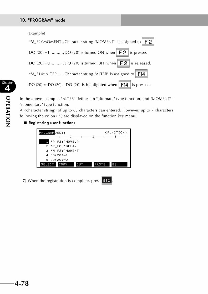
4-78
Chapter
4
OPER
ATIO
N
10. "PROGRAM" mode
4-79
Example)
*M_F2:’MOMENT .. Character string "MOMENT" is assigned to .
DO (20) =1 .......... DO (20) is turned ON when is pressed.
DO (20) =0 ........... DO (20) is turned OFF when is released.
*M_F14:’ALTER ..... Character string "ALTER" is assigned to .
DO (20) =~DO (20) .. DO (20) is highlighted when is pressed.
In the above example, "ALTER" defines an "alternate" type function, and "MOMENT" a
"momentary" type function.
A <character string> of up to 65 characters can entered. However, up to 7 characters
following the colon ( : ) are displayed on the function key menu.
■ Registering user functions
PROGRAM>EDIT <FUNCTION>
1 *P_F2:’MOVE,P
2 *P_F8:’DELAY
3 *M_F2:’MOMENT
4 DO(20)=1
5 DO(20)=0
SELECT COPY CUT PASTE BS
———————————————————————————————————————————1 2 3
7) When the registration is complete, press .

4-78 4-79
Chapter
4
OPER
ATIO
N
10. "PROGRAM" mode
10.7 Resetting an error in the selected programIf an error "9.1 Program destroyed" occurs in the selected program data, this function
resets the error and allows you to continue editing.
cCAUTIONThis function resets an error, but does not restore the program data. A problem is probably occurring in the program, so check and correct the program in "PROGRAM>EDIT" mode.
n NOTE
• Thisfunctionisenabledforeachprogram.
• Thisresetfunctiondoesnotworkifanerror"9.3Memorydestroyed"
occurs. In this case, initialize the memory.
[Procedure]
1) Press (ERR. RST) in "PROGRAM" mode.
A confirmation message appears on the guideline.
■ Resetting an error in the selected program
PROGRAM <TEST2 >
1 ’***** TEST2 PROGRAM *****
2 GOSUB *SUBPROG
3 DO2(0)=-^23-OFW
4 WAIT DI3(4,3,2)=3
5 MOVE P,P0 ’ORIGIN
Error reset OK?
———————————————————————————————————————————1 2 3
YES NO
>ERROR RESET
2) Press (YES) to reset the error.
The program can be edited after resetting the error.
Press (NO) if you want to cancel the error reset.

4-80
Chapter
4
OPER
ATIO
N
4-81
11. "MANUAL" mode
11. "MANUAL" modePoint data and shift data coordinates can be defined and edited in "MANUAL" mode.
The initial "MANUAL" mode screen is shown below.
■ "MANUAL" mode
oGuideline
MANUAL 50%[MG][S0H0X]
s@ —————————————————————————————————————
Current position
*Mx= 0.00 *My= 0.00 *Mz= 0.00
*Mr= 0.00
POINT PALLET VEL+ VEL-
qMode hierarchy wManual movement speed
eRobot group
uSequence program execution mark
yOnline command execution mark
iCurrent position
rSHIFT/HAND /coordinate units
tMessage line
q Mode hierarchy
Shows the current mode hierarchy. When the highest mode ("MANUAL" in this case)
is highlighted it means the servomotor power is on. When not highlighted it means
the servomotor power is off.
w Manual movement speed
Shows the robot movement speed selected for manual operation.
e Robot group
This shows the robot group currently selected for manual movement.
When one robot is specified, only "[MG]" (main group) appears.
r SHIFT/HAND/coordinate units
Shows the shift coordinate number, hand definition number and coordinate units.
t Message line
If an error occurs, the error message appears here. A dashed line ( - - - - ) means
return-to-origin is incomplete. A solid line ( —— ) means return-to-origin return is
complete.
y Online command execution mark
When an online command is being executed, a "@" mark is displayed in the second
column on the second line. This mark changes to a dot "." when the online command
ends.
u Sequence program execution mark
When a sequence program is being executed, an "s" mark is displayed in the first
column on the second line.
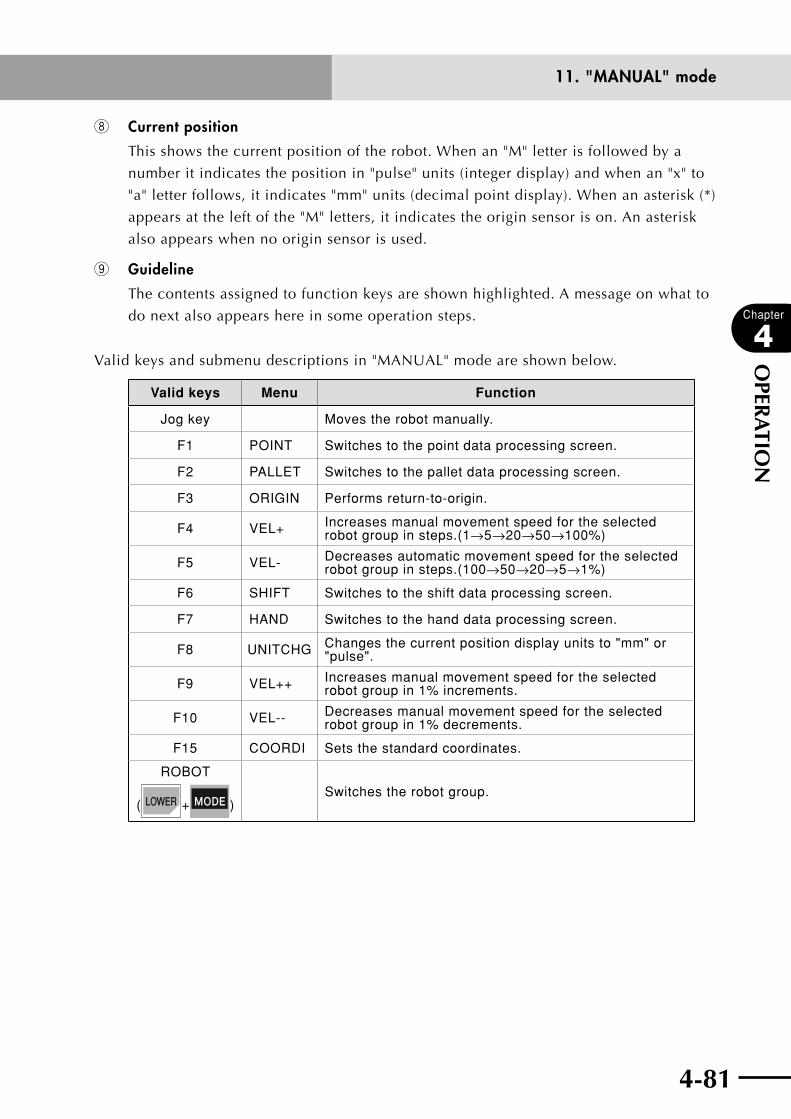
4-80 4-81
Chapter
4
OPER
ATIO
N
11. "MANUAL" mode
i Current position
This shows the current position of the robot. When an "M" letter is followed by a
number it indicates the position in "pulse" units (integer display) and when an "x" to
"a" letter follows, it indicates "mm" units (decimal point display). When an asterisk (*)
appears at the left of the "M" letters, it indicates the origin sensor is on. An asterisk
also appears when no origin sensor is used.
o Guideline
The contents assigned to function keys are shown highlighted. A message on what to
do next also appears here in some operation steps.
Valid keys and submenu descriptions in "MANUAL" mode are shown below.
Valid keys Menu Function
Jog key Moves the robot manually.
F1 POINT Switches to the point data processing screen.
F2 PALLET Switches to the pallet data processing screen.
F3 ORIGIN Performs return-to-origin.
F4 VEL+ Increases manual movement speed for the selected robot group in steps.(1→5→20→50→100%)
F5 VEL- Decreases automatic movement speed for the selected robot group in steps.(100→50→20→5→1%)
F6 SHIFT Switches to the shift data processing screen.
F7 HAND Switches to the hand data processing screen.
F8 UNITCHG Changes the current position display units to "mm" or "pulse".
F9 VEL++ Increases manual movement speed for the selected robot group in 1% increments.
F10 VEL-- Decreases manual movement speed for the selected robot group in 1% decrements.
F15 COORDI Sets the standard coordinates.
ROBOT
( + )Switches the robot group.
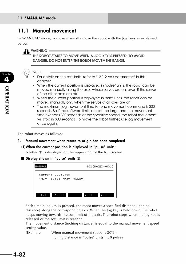
4-82
Chapter
4
OPER
ATIO
N
4-83
11. "MANUAL" mode
11.1 Manual movementIn "MANUAL" mode, you can manually move the robot with the Jog keys as explained
below.
wWARNINGTHE ROBOT STARTS TO MOVE WHEN A jOG kEY IS PRESSED. TO AVOID DANGER, DO NOT ENTER THE ROBOT MOVEMENT RANGE.
n NOTE• Fordetailsonthesoftlimits,referto"12.1.2Axisparameters"inthis
chapter.• Whenthecurrentpositionisdisplayedin"pulse"units,therobotcanbe
moved manually along the axes whose servos are on, even if the servos of the other axes are off.
• Whenthecurrentpositionisdisplayedin"mm"units,therobotcanbemoved manually only when the servos of all axes are on.
• Themaximumjogmovementtimeforonemovementcommandis300seconds. So if the software limits are set too large and the movement time exceeds 300 seconds at the specified speed, the robot movement will stop in 300 seconds. To move the robot further, use jog movement once again.
The robot moves as follows:
1. Manual movement when return-to-origin has been completed
(1) When the current position is displayed in "pulse" units:A letter "J" is displayed on the upper right of the RPB screen.
■ Display shown in "pulse" units (J)
————————————————————————————————————————
*M1= 12521 *M2= -52204
MANUAL 50%[MG][S0H0J]
Current position
POINT PALLET VEL+ VEL-
Each time a Jog key is pressed, the robot moves a specified distance (inching distance) along the corresponding axis. When the Jog key is held down, the robot keeps moving towards the soft limit of the axis. The robot stops when the Jog key is released or the soft limit is reached. The movement distance (inching distance) is equal to the manual movement speed setting value.[Example] When manual movement speed is 20%: Inching distance in "pulse" units = 20 pulses
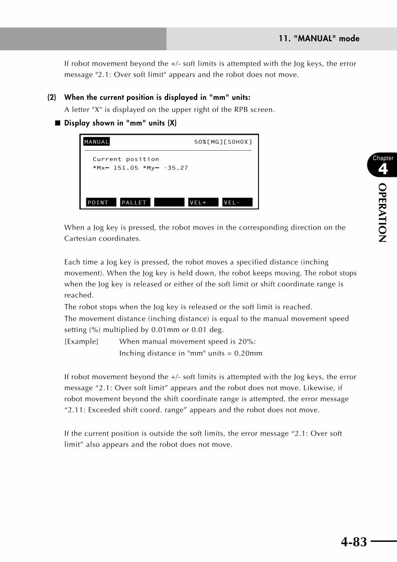
4-82 4-83
Chapter
4
OPER
ATIO
N
11. "MANUAL" mode
If robot movement beyond the +/- soft limits is attempted with the Jog keys, the error
message "2.1: Over soft limit" appears and the robot does not move.
(2) When the current position is displayed in "mm" units:
A letter "X" is displayed on the upper right of the RPB screen.
■ Display shown in "mm" units (X)
————————————————————————————————————————
*Mx= 151.05 *My= -35.27
MANUAL 50%[MG][S0H0X]
Current position
POINT PALLET VEL+ VEL-
When a Jog key is pressed, the robot moves in the corresponding direction on the
Cartesian coordinates.
Each time a Jog key is pressed, the robot moves a specified distance (inching
movement). When the Jog key is held down, the robot keeps moving. The robot stops
when the Jog key is released or either of the soft limit or shift coordinate range is
reached.
The robot stops when the Jog key is released or the soft limit is reached.
The movement distance (inching distance) is equal to the manual movement speed
setting (%) multiplied by 0.01mm or 0.01 deg.
[Example] When manual movement speed is 20%:
Inching distance in "mm" units = 0.20mm
If robot movement beyond the +/- soft limits is attempted with the Jog keys, the error
message “2.1: Over soft limit” appears and the robot does not move. Likewise, if
robot movement beyond the shift coordinate range is attempted, the error message
“2.11: Exceeded shift coord. range” appears and the robot does not move.
If the current position is outside the soft limits, the error message “2.1: Over soft
limit” also appears and the robot does not move.

4-84
Chapter
4
OPER
ATIO
N
4-85
11. "MANUAL" mode
2. When return-to-origin is not complete
cCAUTION• ifreturn-to-originisincomplete,thesoftlimitsdonotworkcorrectly.• ifapHAserseriesrobotisoperatedwhilereturn-to-originisstill
incomplete, the necessary thrust cannot be obtained, causing an alarm or abnormal movement. Always first perform return-to-origin before starting robot operation.
n NOTE
If return-to-origin is incomplete, the current position always appears as
"pulse" units when the controller is turned on.
(1) When the current position is displayed in "pulse" units:Robot movement with the Jog keys is possible the same as when return-to-origin is
complete. However, the message "0.1: Origin incomplete" appears when a Jog key is
pressed.
(2) When the current position is displayed in "mm" units:The robot does not move with the Jog keys. The current position display switches
automatically to "pulse" units and the error message "0.1: Origin incomplete"
appears. Performs return-to-origin.

4-84 4-85
Chapter
4
OPER
ATIO
N
11. "MANUAL" mode
11.2 Displaying and editing point data
Press (POINT) in "MANUAL" mode to enter "MANUAL>POINT" mode. This mode
allows you to display and edit the point data.
One point is made up of data from 6 axes (x, y, z, r, a, b).
The RCX22 series uses only two axes (X, Y).
Point numbers can be specified in the range of 0 to 9999.
The axis data for three points is displayed on the screen along with a point comment on
the selected point number. To see the other data, scroll the screen with the cursor keys or
page keys.
Scrolls up or down one line at a time.
Scrolls right or left one character at a time.
Scrolls up or down three lines at a time.
Scrolls right or left one page at a time.
The 5-digit area on the left side shows the point numbers, with the point number for
editing shown highlighted.
■ Point data
MANUAL>POINT 50% [MG][S0H0J]
————————————x———————y———————z———————r———
P7 = 100.00 250.00
P8 =
P9 = 122.62 -24.54
EDIT TEACH JUMP VEL+ VEL-
COMNT : [ ]
[POS] 50.00 100.00 0.00 0.00
0.00 0.00
0.00 0.00

4-86
Chapter
4
OPER
ATIO
N
4-87
11. "MANUAL" mode
Valid keys and submenu descriptions in "MANUAL>POINT" mode are shown below.
Valid keys Menu Function
Cursor key ( ↑ / ↓ ) Specifies the point data and scrolls the screen.
Page key (
〈〈 / 〈〈 ) Switches to other screens.
F1 EDIT Enters point data with keys.
F2 TEACH Enters point data by teaching.
F3 JUMP Shows the specified point data.
F4 VEL+ Increases manual movement speed for the selected robot group in steps. (1→5→20→50→100%)
F5 VEL- Decreases automatic movement speed for the selected robot group in steps. (100→50→20→5→1%)
F6 COPY Copies point data.
F7 ERASE Deletes point data.
F8 UNITCHG Changes the current position display units to "mm" or "pulse".
F9 VEL++ Increases manual movement speed for the selected robot group in 1% increments.
F10 VEL-- Decreases manual movement speed for the selected robot group in 1% decrements.
F11 TRACE Moves the arm to the specified point.
F12 COMMENT Switches to the point comment edit screen.
F13 ERR.RST Allows editing even if the point data is destroyed.
F14 AXIS← Moves the cursor to the left to select another axis. (Enabled only when auxiliary axis is added.)
F15 AXIS→ Moves the cursor to the right to select another axis. (Enabled only when auxiliary axis is added.)
ROBOT
( + )Switches the robot group.

4-86 4-87
Chapter
4
OPER
ATIO
N
11. "MANUAL" mode
11.2.1 Point data input and editing
[Procedure]
1) In "MANUAL>POINT" mode, use the cursor (↑/↓) keys to select the point to edit.
2) Press (EDIT) to enter "MANUAL>POINT>EDIT" mode.
An edit cursor appears at the left end of the point line data that was selected.
■ Editing point data
MANUAL>POINT>EDIT 50% [MG][S0H0J]
————————————x———————y———————z———————r———
P7 = 100.00 250.00
P8 =
P9 = 122562 -24654
UNDO JUMP
COMNT : [ ]
[POS] 50.00 100.00 0.00 0.00
0.00 0.00
0.00 0.00
3) Use to , , , and to enter the point data.
Enter a space to separate between the data for x and y. The data input formats are as
follows.
n NOTE
• EnterpointdataforbothX-axisandY-axis.Ifomitted,"0"willbe
automatically entered for that axis.
• Theerrormessage"Digitnumbererror"appearswhenthedataformatis
wrong. Enter it in the correct format.
•Toenterthedatainjointcoordinates("pulse"units)
Enter an integer of up to 8 digits.
(Even if the input data is less than 8 digits, it will be displayed in 8 digits when the
number of display digits is set to 8 in "SYSTEM>PARAM" mode.)
: ±######
(±########)
•ToenterthedatainCartesiancoordinates("mm"units)
Enter a number consisting of an integer portion of up to 5 digits and having 2 or
less places below the decimal point.
(Even if the input data is less than 8 digits, it will be displayed in 8 digits when the
number of display digits is set to 8 in "SYSTEM>PARAM" mode.)
: ±###.##,±####.#,±#####.
(±#####.##,±#####.#,±#######.)
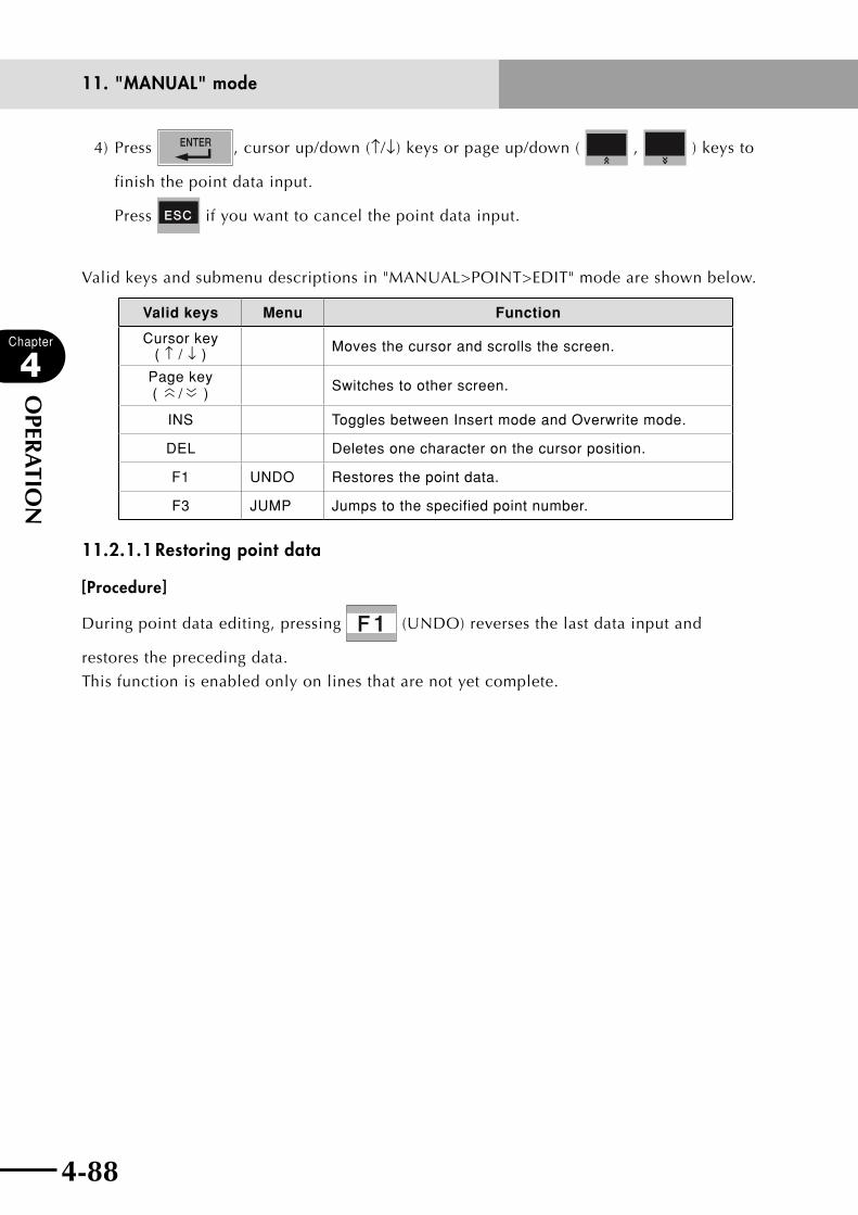
4-88
Chapter
4
OPER
ATIO
N
4-89
11. "MANUAL" mode
4) Press , cursor up/down (↑/↓) keys or page up/down ( , ) keys to
finish the point data input.
Press if you want to cancel the point data input.
Valid keys and submenu descriptions in "MANUAL>POINT>EDIT" mode are shown below.
Valid keys Menu Function
Cursor key ( ↑ / ↓ ) Moves the cursor and scrolls the screen.
Page key (
〈〈 / 〈〈 ) Switches to other screen.
INS Toggles between Insert mode and Overwrite mode.
DEL Deletes one character on the cursor position.
F1 UNDO Restores the point data.
F3 JUMP Jumps to the specified point number.
11.2.1.1 Restoring point data
[Procedure]
During point data editing, pressing (UNDO) reverses the last data input and
restores the preceding data.
This function is enabled only on lines that are not yet complete.
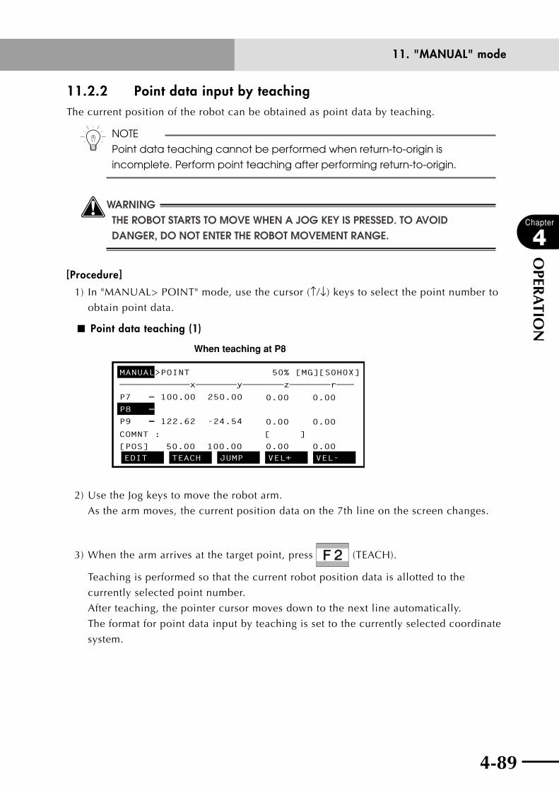
4-88 4-89
Chapter
4
OPER
ATIO
N
11. "MANUAL" mode
11.2.2 Point data input by teachingThe current position of the robot can be obtained as point data by teaching.
n NOTE
Point data teaching cannot be performed when return-to-origin is
incomplete. Perform point teaching after performing return-to-origin.
wWARNINGTHE ROBOT STARTS TO MOVE WHEN A jOG kEY IS PRESSED. TO AVOID DANGER, DO NOT ENTER THE ROBOT MOVEMENT RANGE.
[Procedure]
1) In "MANUAL> POINT" mode, use the cursor (↑/↓) keys to select the point number to
obtain point data.
■ Point data teaching (1)
When teaching at P8
MANUAL>POINT 50% [MG][S0H0X]
————————————x———————y———————z———————r———
P7 = 100.00 250.00
P8 =
P9 = 122.62 -24.54
EDIT TEACH JUMP VEL+ VEL-
COMNT : [ ]
[POS] 50.00 100.00 0.00 0.00
0.00 0.00
0.00 0.00
2) Use the Jog keys to move the robot arm.
As the arm moves, the current position data on the 7th line on the screen changes.
3) When the arm arrives at the target point, press (TEACH).
Teaching is performed so that the current robot position data is allotted to the
currently selected point number.
After teaching, the pointer cursor moves down to the next line automatically.
The format for point data input by teaching is set to the currently selected coordinate
system.
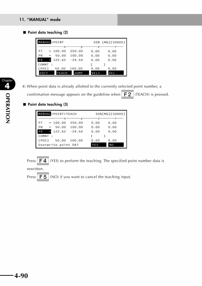
4-90
Chapter
4
OPER
ATIO
N
4-91
11. "MANUAL" mode
■ Point data teaching (2)
MANUAL>POINT 50% [MG][S0H0X]
————————————x———————y———————z———————r———
P7 = 100.00 250.00
P8 = 50.00 100.00
P9 = 122.62 -24.54
EDIT TEACH JUMP VEL+ VEL-
COMNT : [ ][POS] 50.00 100.00 0.00 0.00
0.00 0.00
0.00 0.00
0.00 0.00
4) When point data is already allotted to the currently selected point number, a
confirmation message appears on the guideline when (TEACH) is pressed.
■ Point data teaching (3)
MANUAL>POINT>TEACH 50%[MG][S0H0X]
————————————x———————y———————z———————r———
P7 = 100.00 250.00
P8 = 50.00 100.00
P9 = 122.62 -24.54
Overwrite point OK? YES NO
COMNT : [ ]
[POS] 50.00 100.00 0.00 0.00
0.00 0.00
0.00 0.00
0.00 0.00
Press (YES) to perform the teaching. The specified point number data is
rewritten.
Press (NO) if you want to cancel the teaching input.
4-90 4-91
Chapter
4
OPER
ATIO
N
11. "MANUAL" mode
11.2.3 Point data input by direct teachingPoint data can also be obtained by direct teaching (moving the robot by hand to the target
point while the robot servo is off).
wWARNINGWHEN YOU PERFORM DIRECT TEACHING, MAkE SURE THAT THE EMERGENCY STOP BUTTON IS PRESSED SO THAT THE SERVO WILL NOT TURN ON.
n NOTE
Point data teaching cannot be performed if return-to-origin is incomplete.
n NOTE
When the robot servo is off, automatic and manual operation cannot be
performed. There are two methods for turning on the robot servo: One is to
use the RPB and the other is to use the dedicated input.
Refer to "14. "UTILITY" mode" in this chapter, or refer to "1. Standard I/O
interface overview" in Chapter 5.
[Procedure]
1) Press the emergency stop button on the RPB.
2) Move the robot by hand to the target point and perform point teaching in
"MANUAL>POINT" mode.
For point data teaching methods, refer to the previous section "11.2.2 Point data input
by teaching". (In this procedure you move the robot by hand since the Jog keys cannot
be used.)
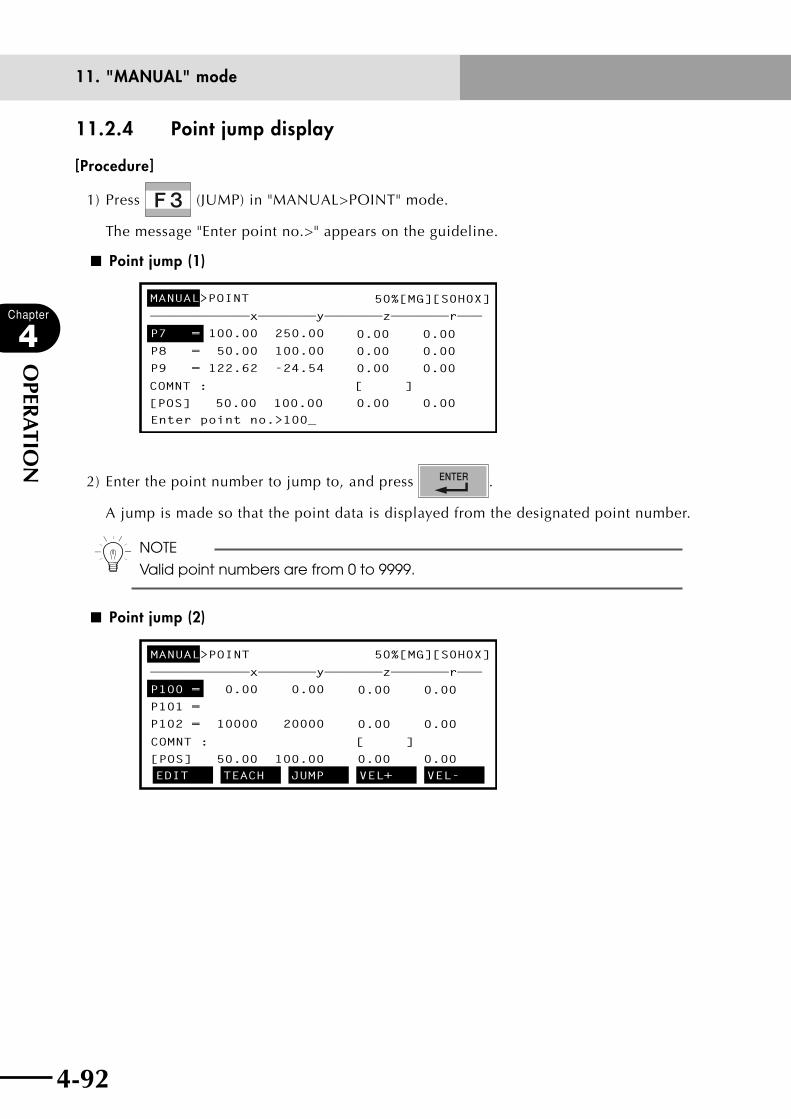
4-92
Chapter
4
OPER
ATIO
N
4-93
11. "MANUAL" mode
11.2.4 Point jump display
[Procedure]
1) Press (JUMP) in "MANUAL>POINT" mode.
The message "Enter point no.>" appears on the guideline.
■ Point jump (1)
MANUAL>POINT 50%[MG][S0H0X]
————————————x———————y———————z———————r———
P7 = 100.00 250.00
P8 = 50.00 100.00
P9 = 122.62 -24.54
Enter point no.>100_
COMNT : [ ]
[POS] 50.00 100.00 0.00 0.00
0.00 0.00
0.00 0.00
0.00 0.00
2) Enter the point number to jump to, and press .
A jump is made so that the point data is displayed from the designated point number.
n NOTE
Valid point numbers are from 0 to 9999.
■ Point jump (2)
MANUAL>POINT 50%[MG][S0H0X]
————————————x———————y———————z———————r———
P100 = 0.00 0.00
P101 =
P102 = 10000 20000
EDIT TEACH JUMP VEL+ VEL-
COMNT : [ ]
[POS] 50.00 100.00 0.00 0.00
0.00 0.00
0.00 0.00

4-92 4-93
Chapter
4
OPER
ATIO
N
11. "MANUAL" mode
11.2.5 Copying point dataPoint data can be copied under another point number.
n NOTE
If a hand system flag is set in the point data, the hand system flag will also
be copied.
[Procedure]
1) Press (COPY) in "MANUAL>POINT" mode.
The message "Copy(####-####,####)>" appears on the guideline.
■ Copying point data (1)
MANUAL>POINT 50% [MG][S0H0X]
————————————x———————y———————z———————r———
P30 = 100.00 250.00
P31 = 50.00 100.00
P32 = 122.62 -24.54
Copy(####-####,####)>
COMNT : [ ]
[POS] 50.00 100.00 0.00 0.00
0.00 0.00
0.00 0.00
0.00 0.00
2) Use to , and to enter the point number range for the copy
source and the point number for the copy destination in the following format and
press .
"(copy start number) – (copy end number), (copy destination number)"
For example, to copy the data between P30 and P34 onto the lines after P50, enter
"30 - 34, 50" and press .
A confirmation message appears on the guideline.
n NOTE
Valid point numbers are from 0 to 9999.

4-94
Chapter
4
OPER
ATIO
N
4-95
11. "MANUAL" mode
■ Copying point data (2)
MANUAL>POINT 50% [MG][S0H0X]
————————————x———————y———————z———————r———
P30 = 100.00 250.00
P31 = 50.00 100.00
P32 = 122.62 -24.54
(30-34,50)Copy OK? YES NO
COMNT : [ ]
[POS] 50.00 100.00 0.00 0.00
0.00 0.00
0.00 0.00
0.00 0.00
3) Press (YES) to make a copy.
The point data in the selected range is copied onto the data lines starting from the
specified copy destination number.
Press (NO) if you want to cancel the copy.

4-94 4-95
Chapter
4
OPER
ATIO
N
11. "MANUAL" mode
11.2.6 Erasing point data
[Procedure]
1) Press (ERASE) in "MANUAL>POINT" mode.
The message "Erase (####-####)>" appears on the guideline.
■ Erasing point data (1)
MANUAL>POINT 50% [MG][S0H0X]
————————————x———————y———————z———————r———
P30 = 100.00 250.00
P31 = 50.00 100.00
P32 = 122.62 -24.54
Erase(####-####)>
COMNT : [ ]
[POS] 50.00 100.00 0.00 0.00
0.00 0.00
0.00 0.00
0.00 0.00
2) Use to and to specify the point number range in the following format
and press .
"(erase start number) - (erase end number)"
For example, to erase the data between P30 and P34, enter "30-34" and press
.
A confirmation message appears on the guideline.
n NOTE
Valid point numbers are from 0 to 9999.
■ Erasing point data (2)
MANUAL>POINT 50% [MG][S0H0X]
————————————x———————y———————z———————r———
P30 = 100.00 250.00
P31 = 50.00 100.00
P32 = 122.62 -24.54
(30-34)Erase OK? YES NO
COMNT : [ ]
[POS] 50.00 100.00 0.00 0.00
0.00 0.00
0.00 0.00
0.00 0.00
3) Press (YES) to erase the data. The point data in the specified range is erased.
Press (NO) if you want to cancel erasure.
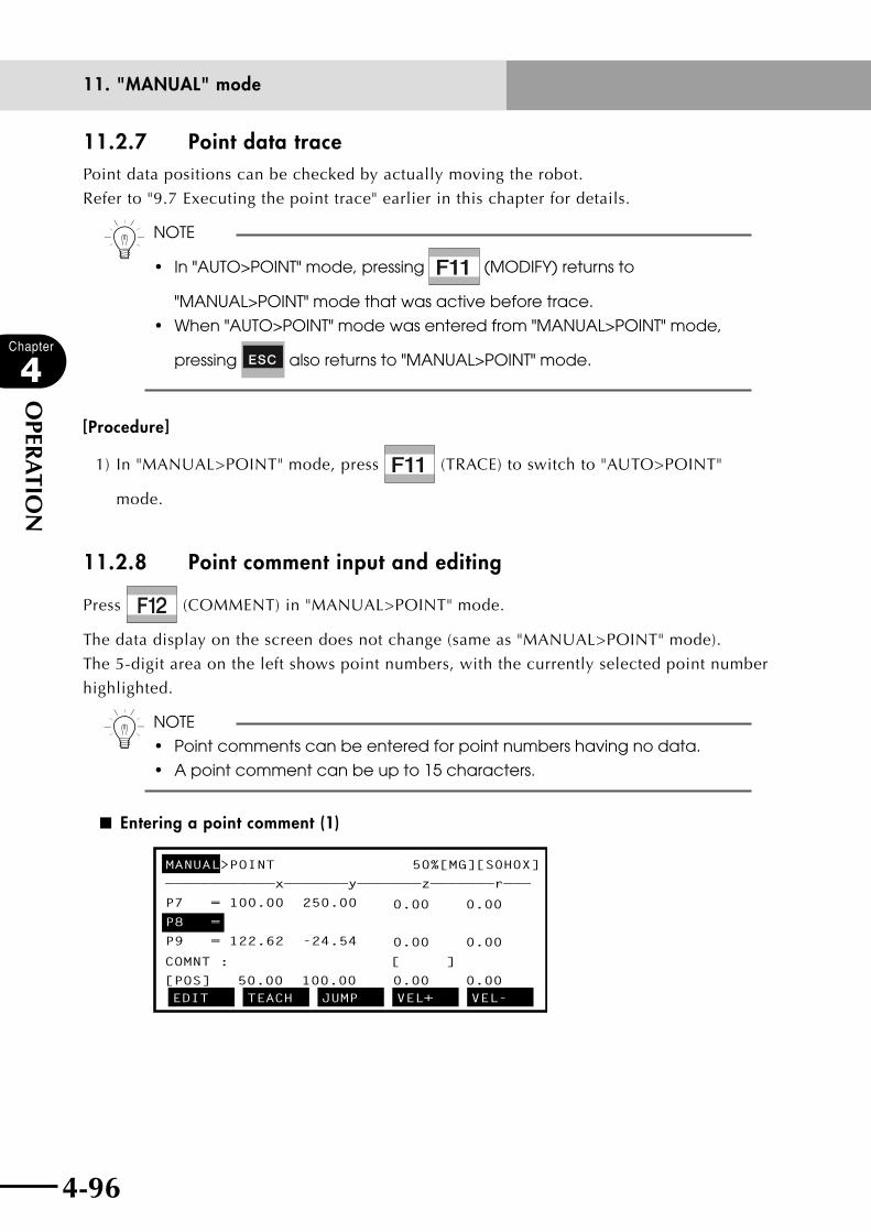
4-96
Chapter
4
OPER
ATIO
N
4-97
11. "MANUAL" mode
11.2.7 Point data tracePoint data positions can be checked by actually moving the robot.
Refer to "9.7 Executing the point trace" earlier in this chapter for details.
n NOTE
• In"AUTO>POINT"mode,pressing (MODIFY) returns to
"MANUAL>POINT" mode that was active before trace.
• When"AUTO>POINT"modewasenteredfrom"MANUAL>POINT"mode,
pressing also returns to "MANUAL>POINT" mode.
[Procedure]
1) In "MANUAL>POINT" mode, press (TRACE) to switch to "AUTO>POINT"
mode.
11.2.8 Point comment input and editing
Press (COMMENT) in "MANUAL>POINT" mode.
The data display on the screen does not change (same as "MANUAL>POINT" mode).
The 5-digit area on the left shows point numbers, with the currently selected point number
highlighted.
n NOTE
• Pointcommentscanbeenteredforpointnumbershavingnodata.
• Apointcommentcanbeupto15characters.
■ Entering a point comment (1)
MANUAL>POINT 50%[MG][S0H0X]
————————————x———————y———————z———————r———
P7 = 100.00 250.00
P8 =
P9 = 122.62 -24.54
EDIT TEACH JUMP VEL+ VEL-
COMNT : [ ]
[POS] 50.00 100.00 0.00 0.00
0.00 0.00
0.00 0.00
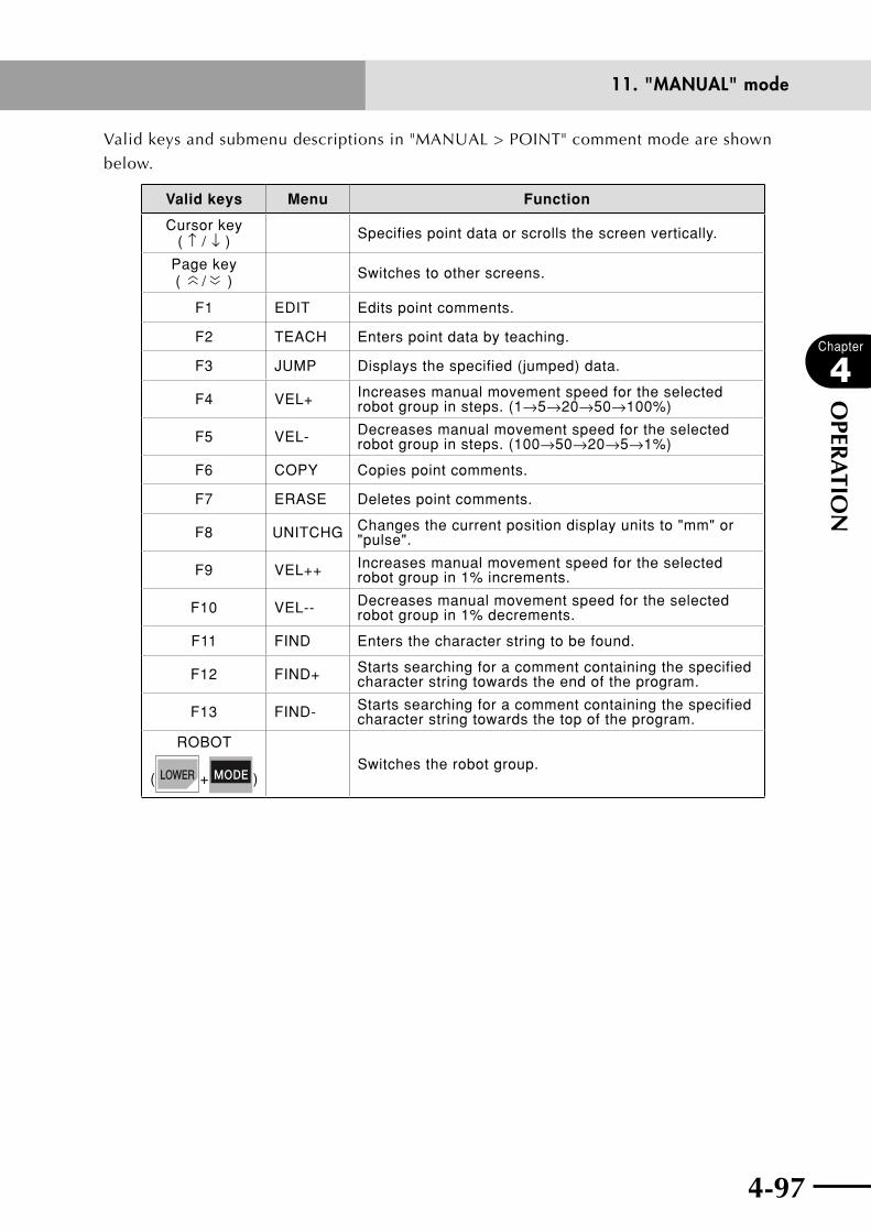
4-96 4-97
Chapter
4
OPER
ATIO
N
11. "MANUAL" mode
Valid keys and submenu descriptions in "MANUAL > POINT" comment mode are shown
below.
Valid keys Menu Function
Cursor key ( ↑ / ↓ ) Specifies point data or scrolls the screen vertically.
Page key (
〈〈 / 〈〈 ) Switches to other screens.
F1 EDIT Edits point comments.
F2 TEACH Enters point data by teaching.
F3 JUMP Displays the specified (jumped) data.
F4 VEL+ Increases manual movement speed for the selected robot group in steps. (1→5→20→50→100%)
F5 VEL- Decreases manual movement speed for the selected robot group in steps. (100→50→20→5→1%)
F6 COPY Copies point comments.
F7 ERASE Deletes point comments.
F8 UNITCHG Changes the current position display units to "mm" or "pulse".
F9 VEL++ Increases manual movement speed for the selected robot group in 1% increments.
F10 VEL-- Decreases manual movement speed for the selected robot group in 1% decrements.
F11 FIND Enters the character string to be found.
F12 FIND+ Starts searching for a comment containing the specified character string towards the end of the program.
F13 FIND- Starts searching for a comment containing the specified character string towards the top of the program.
ROBOT
( + )Switches the robot group.
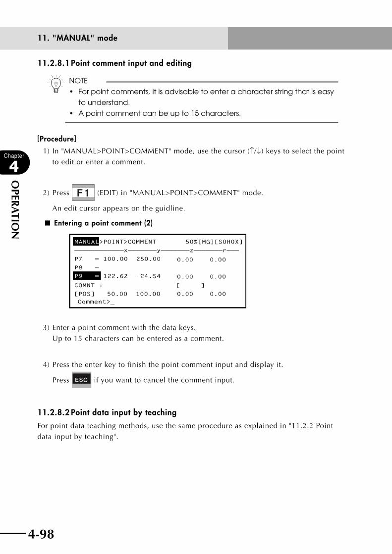
4-98
Chapter
4
OPER
ATIO
N
4-99
11. "MANUAL" mode
11.2.8.1 Point comment input and editing
n NOTE
• Forpointcomments,itisadvisabletoenteracharacterstringthatiseasy
to understand.
• Apointcommentcanbeupto15characters.
[Procedure]
1) In "MANUAL>POINT>COMMENT" mode, use the cursor (↑/↓) keys to select the point
to edit or enter a comment.
2) Press (EDIT) in "MANUAL>POINT>COMMENT" mode.
An edit cursor appears on the guidline.
■ Entering a point comment (2)
MANUAL>POINT>COMMENT 50%[MG][S0H0X]
————————————x———————y———————z———————r———
P7 = 100.00 250.00
P8 =
P9 = 122.62 -24.54
Comment>_
COMNT : [ ]
[POS] 50.00 100.00 0.00 0.00
0.00 0.00
0.00 0.00
3) Enter a point comment with the data keys.
Up to 15 characters can be entered as a comment.
4) Press the enter key to finish the point comment input and display it.
Press if you want to cancel the comment input.
11.2.8.2 Point data input by teaching
For point data teaching methods, use the same procedure as explained in "11.2.2 Point
data input by teaching".
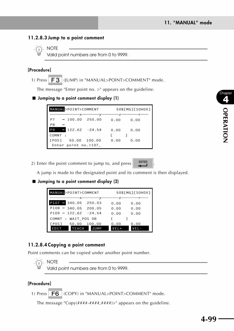
4-98 4-99
Chapter
4
OPER
ATIO
N
11. "MANUAL" mode
11.2.8.3 Jump to a point comment
n NOTE
Valid point numbers are from 0 to 9999.
[Procedure]
1) Press (JUMP) in "MANUAL>POINT>COMMENT" mode.
The message "Enter point no. >" appears on the guideline.
■ Jumping to a point comment display (1)
MANUAL>POINT>COMMENT 50%[MG][S0H0X]
————————————x———————y———————z———————r———
P7 = 100.00 250.00
P8 =
P9 = 122.62 -24.54
Enter point no.>107_
COMNT : [ ]
[POS] 50.00 100.00 0.00 0.00
0.00 0.00
0.00 0.00
2) Enter the point comment to jump to, and press .
A jump is made to the designated point and its comment is then displayed.
■ Jumping to a point comment display (2)
MANUAL>POINT>COMMENT 50%[MG][S0H0X]
————————————x———————y———————z———————r———
P107 = 340.05 250.03
340.05 200.05 P108 =
P109 = 122.62 -24.54
EDIT TEACH JUMP VEL+ VEL-
[ ]COMNT : WAIT_POS 08
[POS] 50.00 100.00 0.00 0.00
0.00 0.00
0.00 0.00
0.00 0.00
11.2.8.4 Copying a point comment
Point comments can be copied under another point number.
n NOTE
Valid point numbers are from 0 to 9999.
[Procedure]
1) Press (COPY) in "MANUAL>POINT>COMMENT" mode.
The message "Copy(####-####,####)>" appears on the guideline.
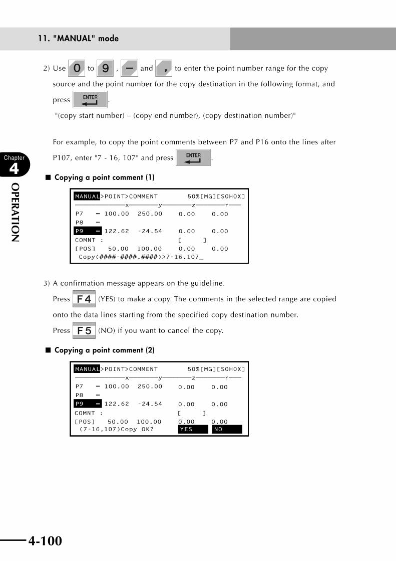
4-100
Chapter
4
OPER
ATIO
N
4-101
11. "MANUAL" mode
2) Use to , and to enter the point number range for the copy
source and the point number for the copy destination in the following format, and
press .
"(copy start number) – (copy end number), (copy destination number)"
For example, to copy the point comments between P7 and P16 onto the lines after
P107, enter "7 - 16, 107" and press .
■ Copying a point comment (1)
MANUAL>POINT>COMMENT 50%[MG][S0H0X]
————————————x———————y———————z———————r———
P7 = 100.00 250.00
P8 =
P9 = 122.62 -24.54
Copy(####-####,####)>7-16,107_
COMNT : [ ]
[POS] 50.00 100.00 0.00 0.00
0.00 0.00
0.00 0.00
3) A confirmation message appears on the guideline.
Press (YES) to make a copy. The comments in the selected range are copied
onto the data lines starting from the specified copy destination number.
Press (NO) if you want to cancel the copy.
■ Copying a point comment (2)
MANUAL>POINT>COMMENT 50%[MG][S0H0X]
————————————x———————y———————z———————r———
P7 = 100.00 250.00
P8 =
P9 = 122.62 -24.54
(7-16,107)Copy OK? YES NO
COMNT : [ ]
[POS] 50.00 100.00 0.00 0.00
0.00 0.00
0.00 0.00
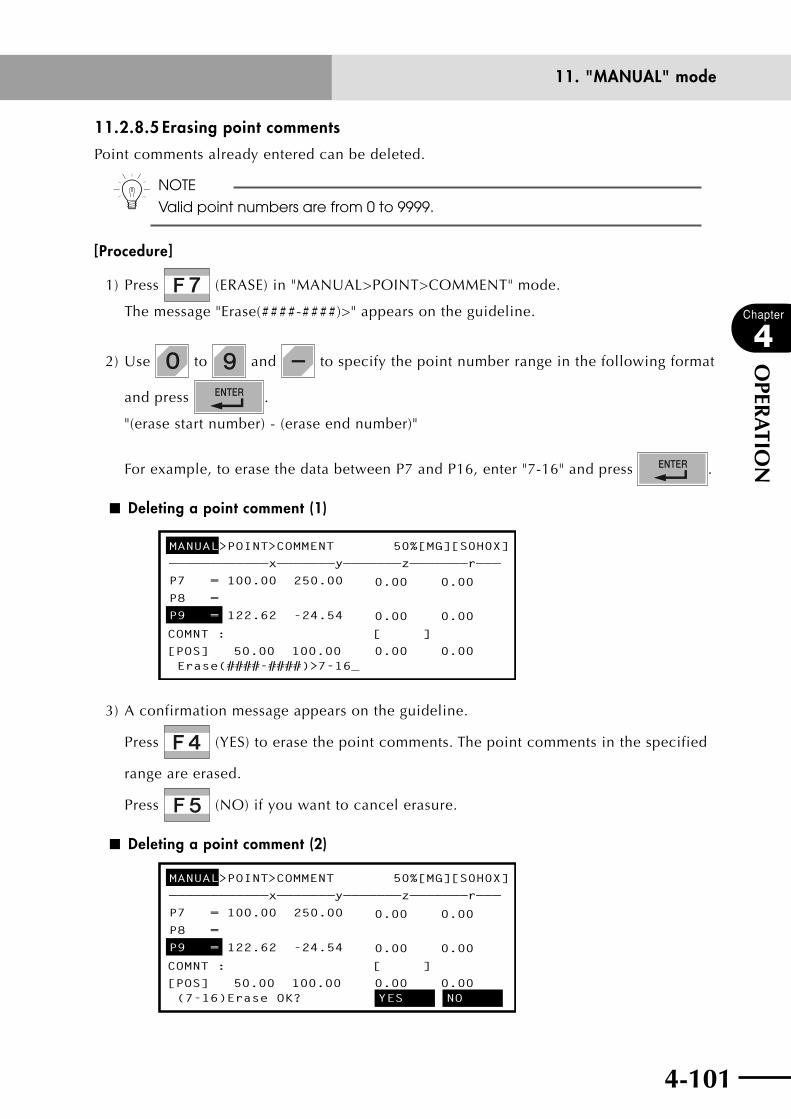
4-100 4-101
Chapter
4
OPER
ATIO
N
11. "MANUAL" mode
11.2.8.5 Erasing point comments
Point comments already entered can be deleted.
n NOTE
Valid point numbers are from 0 to 9999.
[Procedure]
1) Press (ERASE) in "MANUAL>POINT>COMMENT" mode.
The message "Erase(####-####)>" appears on the guideline.
2) Use to and to specify the point number range in the following format
and press .
"(erase start number) - (erase end number)"
For example, to erase the data between P7 and P16, enter "7-16" and press .
■ Deleting a point comment (1)
MANUAL>POINT>COMMENT 50%[MG][S0H0X]
————————————x———————y———————z———————r———
P7 = 100.00 250.00
P8 =
P9 = 122.62 -24.54
Erase(####-####)>7-16_
COMNT : [ ]
[POS] 50.00 100.00 0.00 0.00
0.00 0.00
0.00 0.00
3) A confirmation message appears on the guideline.
Press (YES) to erase the point comments. The point comments in the specified
range are erased.
Press (NO) if you want to cancel erasure.
■ Deleting a point comment (2)
MANUAL>POINT>COMMENT 50%[MG][S0H0X]
————————————x———————y———————z———————r———
P7 = 100.00 250.00
P8 =
P9 = 122.62 -24.54
(7-16)Erase OK? YES NO
COMNT : [ ]
[POS] 50.00 100.00 0.00 0.00
0.00 0.00
0.00 0.00
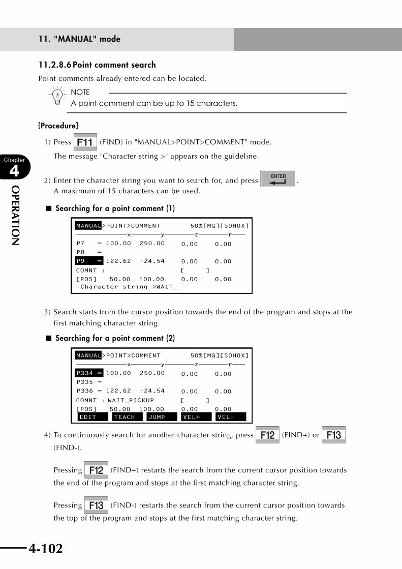
4-102
Chapter
4
OPER
ATIO
N
4-103
11. "MANUAL" mode
11.2.8.6 Point comment search
Point comments already entered can be located.
n NOTE
A point comment can be up to 15 characters.
[Procedure]
1) Press (FIND) in "MANUAL>POINT>COMMENT" mode.
The message "Character string >" appears on the guideline.
2) Enter the character string you want to search for, and press . A maximum of 15 characters can be used.
■ Searching for a point comment (1)
MANUAL>POINT>COMMENT 50%[MG][S0H0X]
————————————x———————y———————z———————r———
P7 = 100.00 250.00
P8 =
P9 = 122.62 -24.54
Character string >WAIT_
COMNT : [ ]
[POS] 50.00 100.00 0.00 0.00
0.00 0.00
0.00 0.00
3) Search starts from the cursor position towards the end of the program and stops at the
first matching character string.
■ Searching for a point comment (2)
MANUAL>POINT>COMMENT 50%[MG][S0H0X]
————————————x———————y———————z———————r———
P334 = 100.00 250.00
P335 =
P336 = 122.62 -24.54
EDIT TEACH JUMP VEL+ VEL-
COMNT : WAIT_PICKUP [ ]
[POS] 50.00 100.00 0.00 0.00
0.00 0.00
0.00 0.00
4) To continuously search for another character string, press (FIND+) or
(FIND-).
Pressing (FIND+) restarts the search from the current cursor position towards
the end of the program and stops at the first matching character string.
Pressing (FIND-) restarts the search from the current cursor position towards
the top of the program and stops at the first matching character string.

4-102 4-103
Chapter
4
OPER
ATIO
N
11. "MANUAL" mode
11.2.9 Point data error resetIf an error "9.2 Point data destroyed" occurs in the point data, this function resets the error
and allows you to continue editing.
cCAUTIONThis function resets an error, but does not restore the point data. A problem is probably occurring in the point data, so check and correct the point data in "MANUAL>POINT>EDIT" mode.
n NOTE
This reset function does not work if an error "9.3 Memory destroyed" occurs.
In this case, initialize the memory.
[Procedure]
1) Press (ERR. RST) in "MANUAL>POINT" mode.
A confirmation message appears on the guideline.
■ Resetting a point data error
MANUAL>POINT 50% [MG][S0H0X]
————— 9.2:Point data destroyed—————————
P30 = 100.00 250.00
P31 = 50.00 100.00
P32 = 122.62 -24.54
Error reset OK? YES NO
COMNT : [ ]
[POS] 50.00 100.00 0.00 0.00
0.00 0.00
0.00 0.00
0.00 0.00
2) Press (YES) to reset the error.
Point data can be edited after resetting the error.
Press (NO) if you want to cancel the error reset.
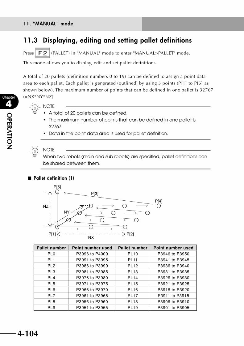
4-104
Chapter
4
OPER
ATIO
N
4-105
11. "MANUAL" mode
11.3 Displaying, editing and setting pallet definitions
Press (PALLET) in "MANUAL" mode to enter "MANUAL>PALLET" mode.
This mode allows you to display, edit and set pallet definitions.
A total of 20 pallets (definition numbers 0 to 19) can be defined to assign a point data
area to each pallet. Each pallet is generated (outlined) by using 5 points (P[1] to P[5] as
shown below). The maximum number of points that can be defined in one pallet is 32767
(=NX*NY*NZ).
n NOTE
•Atotalof20palletscanbedefined.
• Themaximumnumberofpointsthatcanbedefinedinonepalletis
32767.
•Datainthepointdataareaisusedforpalletdefinition.
n NOTE
When two robots (main and sub robots) are specified, pallet definitions can
be shared between them.
■ Pallet definition (1)
P[5]
P[3]
P[4]
P[2]P[1]
NZ
NX
NY
Pallet number Point number used Pallet number Point number used
PL0 P3996 to P4000 PL10 P3946 to P3950PL1 P3991 to P3995 PL11 P3941 to P3945PL2 P3986 to P3990 PL12 P3936 to P3940PL3 P3981 to P3985 PL13 P3931 to P3935PL4 P3976 to P3980 PL14 P3926 to P3930PL5 P3971 to P3975 PL15 P3921 to P3925PL6 P3966 to P3970 PL16 P3916 to P3920PL7 P3961 to P3965 PL17 P3911 to P3915PL8 P3956 to P3960 PL18 P3906 to P3910PL9 P3951 to P3955 PL19 P3901 to P3905
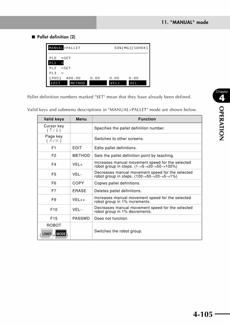
4-104 4-105
Chapter
4
OPER
ATIO
N
11. "MANUAL" mode
■ Pallet definition (2)
MANUAL>PALLET 50%[MG][S0H0X]
PL0 =SET
PL1 =
PL2 =SET
PL3 =
[POS] 400.00 0.00 0.00 0.00
EDIT METHOD VEL+ VEL-
Pallet definition numbers marked "SET" mean that they have already been defined.
Valid keys and submenu descriptions in "MANUAL>PALLET" mode are shown below.
Valid keys Menu Function
Cursor key ( ↑ / ↓ ) Specifies the pallet definition number.
Page key (
〈〈 / 〈〈 ) Switches to other screens.
F1 EDIT Edits pallet definitions.
F2 METHOD Sets the pallet definition point by teaching.
F4 VEL+ Increases manual movement speed for the selected robot group in steps. (1→5→20→50→100%)
F5 VEL- Decreases manual movement speed for the selected robot group in steps. (100→50→20→5→1%)
F6 COPY Copies pallet definitions.
F7 ERASE Deletes pallet definitions.
F9 VEL++ Increases manual movement speed for the selected robot group in 1% increments.
F10 VEL-- Decreases manual movement speed for the selected robot group in 1% decrements.
F15 PASSWD Does not function.
ROBOT
( + )Switches the robot group.
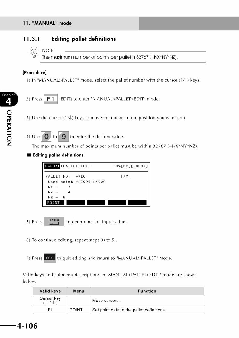
4-106
Chapter
4
OPER
ATIO
N
4-107
11. "MANUAL" mode
11.3.1 Editing pallet definitions
n NOTE
The maximum number of points per pallet is 32767 (=NX*NY*NZ).
[Procedure]
1) In "MANUAL>PALLET" mode, select the pallet number with the cursor (↑/↓) keys.
2) Press (EDIT) to enter "MANUAL>PALLET>EDIT" mode.
3) Use the cursor (↑/↓) keys to move the cursor to the position you want edit.
4) Use to to enter the desired value.
The maximum number of points per pallet must be within 32767 (=NX*NY*NZ).
■ Editing pallet definitions
MANUAL>PALLET>EDIT 50%[MG][S0H0X]
PALLET NO. =PL0 [XY]
Used point =P3996-P4000
NX = 3
NY = 4
NZ = 5_
POINT
5) Press to determine the input value.
6) To continue editing, repeat steps 3) to 5).
7) Press to quit editing and return to "MANUAL>PALLET" mode.
Valid keys and submenu descriptions in "MANUAL>PALLET>EDIT" mode are shown
below.
Valid keys Menu Function
Cursor key ( ↑ / ↓ ) Move cursors.
F1 POINT Set point data in the pallet definitions.

4-106 4-107
Chapter
4
OPER
ATIO
N
11. "MANUAL" mode
11.3.1.1 Point setting in pallet definition
In "MANUAL>PALLET>EDIT" mode, a screen like that shown below is displayed.
n NOTE
• Eachpalletisgeneratedwith5pointsforpalletdefinition.
• These5pointsshouldbedefinedinorderfromP[1]toP[5].See"11.3
Displaying, editing and setting pallet definitions".
■ Point setting in pallet definition
MANUAL>PALLET>EDIT 50%[MG][S0H0X]
POINT=P3996(P[1])-P4000(P[5])
P[1] = 98.87 -24.54
P[2] = 122.62 -24.54
P[3] = 98.62 -94.54
EDIT TEACH VEL+ VEL-
[POS] 50.00 100.00 0.00 0.00
0.00 0.00
0.00 0.00
0.00 0.00
————————————x———————y———————z———————r———
The 3rd line shows the point numbers and point data in the pallet definition.
Valid keys and submenu descriptions in this mode are shown below.
Valid keys Menu Function
Cursor key ( ↑ / ↓ ) Specifies the point data or scrolls the screen.
F1 EDIT Edits the point in pallet definition.
F2 TEACH Sets the point in pallet definition by teaching.
F4 VEL+ Increases manual movement speed for the selected robot group in steps. (1→5→20→50→100%)
F5 VEL- Decreases manual movement speed for the selected robot group in steps. (100→50→20→5→1%)
F8 UNITCHG Switches the current position display units.
F9 VEL++ Increases manual movement speed for the selected robot group in 1% increments.
F10 VEL-- Decreases manual movement speed for the selected robot group in 1% decrements.
ROBOT
( + )Switches the robot group.

4-108
Chapter
4
OPER
ATIO
N
4-109
11. "MANUAL" mode
11.3.1.1.1 Editing the point in pallet definition
n NOTE
• Eachpalletisgenerated(outlined)with5points,soalwaysspecifythese
5 points for pallet definition.
• Pointdatainthepalletdefinitionmustbeenteredin"mm"units.
• The5pointsshouldbedefinedinorderfromP[1]toP[5].See"11.3
Displaying, editing and setting pallet definitions".
[Procedure]
1) Press (EDIT) in "MANUAL>PALLET>EDIT>POINT" mode.
■ Point editing in pallet definition
MANUAL>PALLET>EDIT 50%[MG][S0H0X]
POINT=P3996(P[1])-P4000(P[5])
P[1] = _98.87 -24.54
P[2] = 122.62 -24.54
P[3] = 98.62 -94.54
UNDO
[POS] 50.00 100.00 0.00 0.00
0.00 0.00
0.00 0.00
0.00 0.00
————————————x———————y———————z———————r———
2) Use the cursor (←/→/↑/↓) keys to move the cursor to the position you want edit.
3) Use to , , , and to enter the point data.
4) Press or cursor up/down (↑/↓) keys to finish the point data input.
Press if you want to cancel the point data input.
5) To continue editing, repeat steps 2) to 4).
6) Press to quit editing and return to "MANUAL>PALLET >EDIT>POINT" mode.
Valid keys and submenu descriptions in this mode are shown below.
Valid keys Menu Function
Cursor key ( ↑ / ↓ ) Moves the cursor.
F1 undo Reverses the last data input and restores the preceding data.
11.3.1.1.2 Setting the point in pallet definition by teaching
For point data teaching methods, refer to "11.2.2 Point data input by teaching".

4-108 4-109
Chapter
4
OPER
ATIO
N
11. "MANUAL" mode
11.3.2 Pallet definition by teaching
n NOTE
Pallets cannot be defined by teaching if return-to-origin is incomplete.
Perform teaching after performing return-to-origin.
[Procedure]
1) Select the pallet number in "MANUAL>PALLET" mode with the cursor (↑/↓) keys.
2) Press (METHOD) to enter "MANUAL>PALLET>METHOD" mode.
3) Select the dimension of the pallet to be defined from "2-D" (plane) or "3-D" (solid).
■ Pallet definition by teaching (1)
MANUAL>PALLET>METHOD 50%[MG][S0H0X]
PALLET NO.=PL0 [XY]
Select dimension of this pallet
2-D 3-D
4) Move the robot work point to P[1] used in the pallet definition, and perform teaching
by pressing .
wWARNINGTO AVOID HAzARDOUS SITUATIONS DO NOT ENTER THE ROBOT MOVEMENT RANGE WHEN MANIPULATING THE ROBOT.
n NOTE
•Eachpalletisgenerated(outlined)with5pointsforpalletdefinition.
•Pointdatainthepalletdefinitionmustbeenteredin"mm"units.
• The5pointsshouldbedefinedinorderfromP[1]toP[5].See"11.3
Displaying, editing and setting pallet definitions".
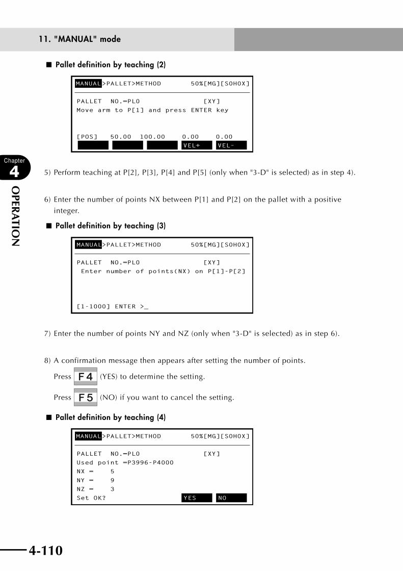
4-110
Chapter
4
OPER
ATIO
N
4-111
11. "MANUAL" mode
■ Pallet definition by teaching (2)
MANUAL>PALLET>METHOD 50%[MG][S0H0X]
PALLET NO.=PL0 [XY]
Move arm to P[1] and press ENTER key
VEL+ VEL–
[POS] 50.00 100.00 0.00 0.00
5) Perform teaching at P[2], P[3], P[4] and P[5] (only when "3-D" is selected) as in step 4).
6) Enter the number of points NX between P[1] and P[2] on the pallet with a positive
integer.
■ Pallet definition by teaching (3)
MANUAL>PALLET>METHOD 50%[MG][S0H0X]
PALLET NO.=PL0 [XY]
Enter number of points(NX) on P[1]-P[2]
[1-1000] ENTER >_
7) Enter the number of points NY and NZ (only when "3-D" is selected) as in step 6).
8) A confirmation message then appears after setting the number of points.
Press (YES) to determine the setting.
Press (NO) if you want to cancel the setting.
■ Pallet definition by teaching (4)
MANUAL>PALLET>METHOD 50%[MG][S0H0X]
PALLET NO.=PL0 [XY]
Used point =P3996-P4000
NX = 5
NY = 9
NZ = 3
Set OK? YES NO
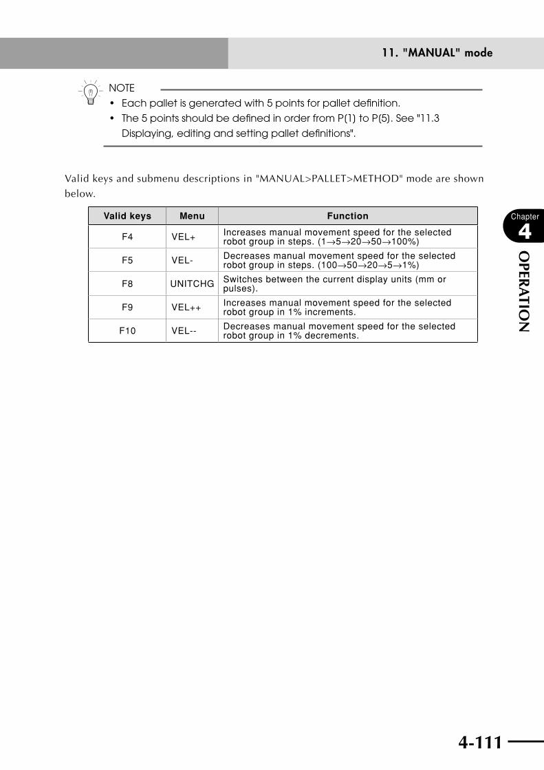
4-110 4-111
Chapter
4
OPER
ATIO
N
11. "MANUAL" mode
n NOTE
• Eachpalletisgeneratedwith5pointsforpalletdefinition.
• The5pointsshouldbedefinedinorderfromP[1]toP[5].See"11.3
Displaying, editing and setting pallet definitions".
Valid keys and submenu descriptions in "MANUAL>PALLET>METHOD" mode are shown
below.
Valid keys Menu Function
F4 VEL+ Increases manual movement speed for the selected robot group in steps. (1→5→20→50→100%)
F5 VEL- Decreases manual movement speed for the selected robot group in steps. (100→50→20→5→1%)
F8 UNITCHG Switches between the current display units (mm or pulses).
F9 VEL++ Increases manual movement speed for the selected robot group in 1% increments.
F10 VEL-- Decreases manual movement speed for the selected robot group in 1% decrements.
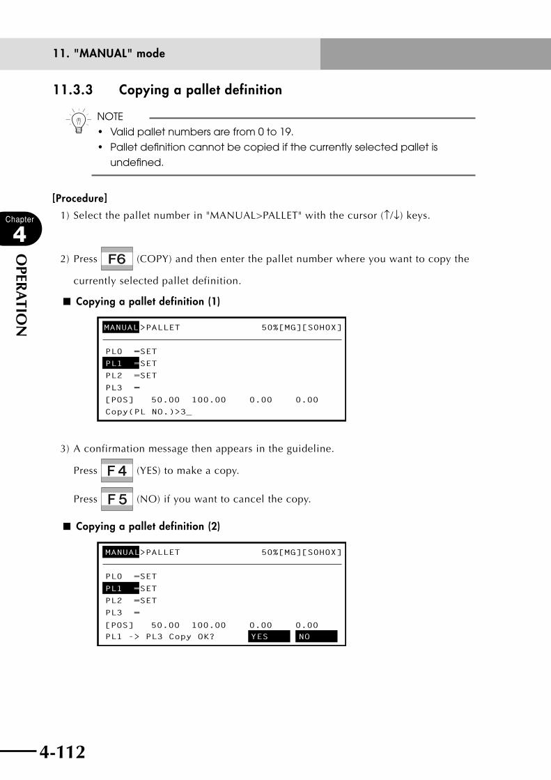
4-112
Chapter
4
OPER
ATIO
N
4-113
11. "MANUAL" mode
11.3.3 Copying a pallet definition
n NOTE
• Validpalletnumbersarefrom0to19.
• Palletdefinitioncannotbecopiedifthecurrentlyselectedpalletis
undefined.
[Procedure]
1) Select the pallet number in "MANUAL>PALLET" with the cursor (↑/↓) keys.
2) Press (COPY) and then enter the pallet number where you want to copy the
currently selected pallet definition.
■ Copying a pallet definition (1)
MANUAL>PALLET 50%[MG][S0H0X]
PL0 =SET
PL1 =SET
PL2 =SET
PL3 =
Copy(PL NO.)>3_
[POS] 50.00 100.00 0.00 0.00
3) A confirmation message then appears in the guideline.
Press (YES) to make a copy.
Press (NO) if you want to cancel the copy.
■ Copying a pallet definition (2)
MANUAL>PALLET 50%[MG][S0H0X]
PL0 =SET
PL1 =SET
PL2 =SET
PL3 =
PL1 -> PL3 Copy OK? YES NO[POS] 50.00 100.00 0.00 0.00
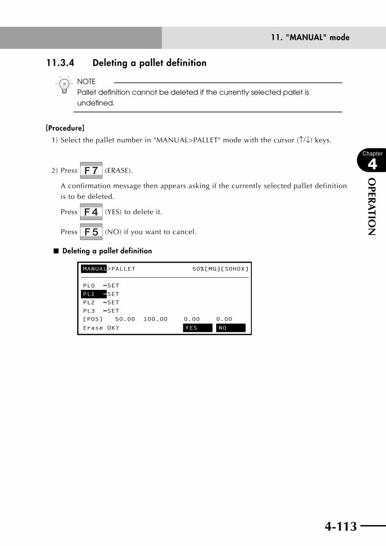
4-112 4-113
Chapter
4
OPER
ATIO
N
11. "MANUAL" mode
11.3.4 Deleting a pallet definition
n NOTE
Pallet definition cannot be deleted if the currently selected pallet is
undefined.
[Procedure]
1) Select the pallet number in "MANUAL>PALLET" mode with the cursor (↑/↓) keys.
2) Press (ERASE).
A confirmation message then appears asking if the currently selected pallet definition
is to be deleted.
Press (YES) to delete it.
Press (NO) if you want to cancel.
■ Deleting a pallet definition
MANUAL>PALLET 50%[MG][S0H0X]
PL0 =SET
PL1 =SET
PL2 =SET
PL3 =SET
Erase OK? YES NO
[POS] 50.00 100.00 0.00 0.00
4-114
Chapter
4
OPER
ATIO
N
4-115
11. "MANUAL" mode
11.4 Changing the manual movement speedManual movement speed of the selected robot group can be set anywhere within the range
from 1 to 100%. Movement speed in "MANUAL" mode is set separately from the "AUTO"
mode movement speed. One-fifth of the maximum speed in "AUTO" mode is equal to the
maximum movement speed in "MANUAL" mode.
[Procedure]
1) Press (VEL+) or (VEL-) to change the manual movement speed in steps.
Each time this key is pressed, the speed changes in steps of 1 ← → 5 ← → 20 ← →
50 ← → 100%. The maximum motor speed is set at 100%.
2) Press (VEL++) or (VEL--) to change the manual movement speed
gradually.
Each time this key is pressed, the speed changes in units of 1%.
Holding down the key changes the speed continuously.
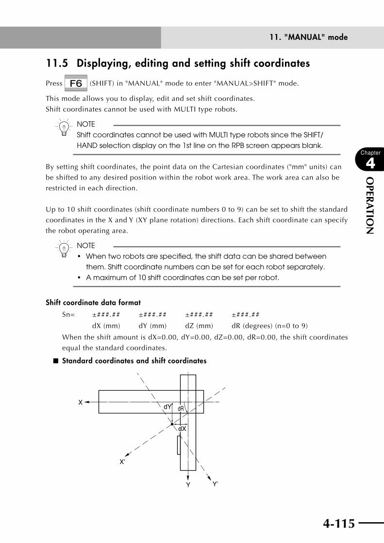
4-114 4-115
Chapter
4
OPER
ATIO
N
11. "MANUAL" mode
11.5 Displaying, editing and setting shift coordinates
Press (SHIFT) in "MANUAL" mode to enter "MANUAL>SHIFT" mode.
This mode allows you to display, edit and set shift coordinates.
Shift coordinates cannot be used with MULTI type robots.
n NOTE
Shift coordinates cannot be used with MULTI type robots since the SHIFT/
HAND selection display on the 1st line on the RPB screen appears blank.
By setting shift coordinates, the point data on the Cartesian coordinates ("mm" units) can
be shifted to any desired position within the robot work area. The work area can also be
restricted in each direction.
Up to 10 shift coordinates (shift coordinate numbers 0 to 9) can be set to shift the standard
coordinates in the X and Y (XY plane rotation) directions. Each shift coordinate can specify
the robot operating area.
n NOTE
• Whentworobotsarespecified,theshiftdatacanbesharedbetween
them. Shift coordinate numbers can be set for each robot separately.
• Amaximumof10shiftcoordinatescanbesetperrobot.
Shift coordinate data format
Sn= ±###.## ±###.## ±###.## ±###.##
dX (mm) dY (mm) dZ (mm) dR (degrees) (n=0 to 9)
When the shift amount is dX=0.00, dY=0.00, dZ=0.00, dR=0.00, the shift coordinates
equal the standard coordinates.
■ Standard coordinates and shift coordinates
X
X’
Y Y’
dRdRdY
dXdX
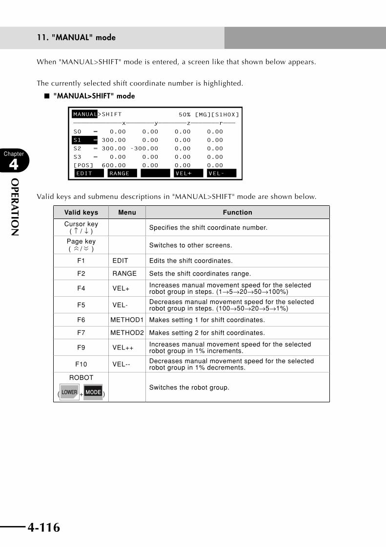
4-116
Chapter
4
OPER
ATIO
N
4-117
11. "MANUAL" mode
When "MANUAL>SHIFT" mode is entered, a screen like that shown below appears.
The currently selected shift coordinate number is highlighted.
■ "MANUAL>SHIFT" mode
MANUAL>SHIFT 50% [MG][S1H0X]
————————————x———————y———————z———————r———
S0 = 0.00 0.00 0.00 0.00
S1 = 300.00 0.00 0.00
0.00
0.00
S2 = 300.00 -300.00 0.00
0.00S3 = 0.00 0.00 0.00
[POS] 600.00 0.00 0.00 0.00EDIT RANGE VEL+ VEL-
Valid keys and submenu descriptions in "MANUAL>SHIFT" mode are shown below.
Valid keys Menu Function
Cursor key ( ↑ / ↓ ) Specifies the shift coordinate number.
Page key (
〈〈 / 〈〈 ) Switches to other screens.
F1 EDIT Edits the shift coordinates.
F2 RANGE Sets the shift coordinates range.
F4 VEL+ Increases manual movement speed for the selected robot group in steps. (1→5→20→50→100%)
F5 VEL- Decreases manual movement speed for the selected robot group in steps. (100→50→20→5→1%)
F6 METHOD1 Makes setting 1 for shift coordinates.
F7 METHOD2 Makes setting 2 for shift coordinates.
F9 VEL++ Increases manual movement speed for the selected robot group in 1% increments.
F10 VEL-- Decreases manual movement speed for the selected robot group in 1% decrements.
ROBOT
( + )Switches the robot group.

4-116 4-117
Chapter
4
OPER
ATIO
N
11. "MANUAL" mode
11.5.1 Editing shift coordinates
[Procedure]
1) In the "MANUAL>SHIFT" mode, select a shift coordinate number with the cursor (↑/↓)
keys.
2) Press (EDIT) to enter "MANUAL>SHIFT>EDIT" mode.
3) Use the cursor (←/→) key to move the cursor to the position you want to change.
4) Use to , , , and to enter the shift coordinate data.
Enter a space to separate between the data for x and y. The data input formats are as
follows.
•ToenterthedatainCartesiancoordinates("mm"units)
Enter a number consisting of an integer portion of up to 5 digits and having 2 or
less places below the decimal point.
±###.##, ±####.#, ±#####.
n NOTE
Enter point data for both X-axis and Y-axis. If omitted, "0" will be
automatically entered for that axis.
■ Editing shift coordinate data
MANUAL>SHIFT>EDIT 50% [MG][S1H0X]
————————————x———————y———————z———————r———
S0 = 0.00 0.00 0.00 0.00
0.00 0.00
0.00 0.00
0.00
S1 = 300.00 0.00
S2 = 300.00 -300.00
S3 = 0.00 0.00 0.00
[POS] 600.00 0.00 0.00 0.00
UNDO
5) Press , cursor up/down (↑/↓) keys or page up/down ( , ) keys to
finish the data input.
Press if you want to cancel the data input.
6) To continue the editing, repeat steps 3) to 5).

4-118
Chapter
4
OPER
ATIO
N
4-119
11. "MANUAL" mode
7) Press to quit editing and return to "MANUAL>SHIFT" mode.
n NOTE
The shift coordinate data on which the cursor was positioned when returning
to "MANUAL>SHIFT" mode is used as the shift coordinates for the currently
selected robot group.
Valid keys and submenu descriptions in "MANUAL>SHIFT>EDIT" mode are shown below.
Valid keys Menu Function
F1 UNDO Reverses the last data input and restores the preceding data.
11.5.1.1 Restoring shift coordinates
[Procedure]
1) During shift coordinate data editing, pressing (UNDO) reverses the last data
input and restores the preceding data.
This function is enabled only on lines that are not yet complete.
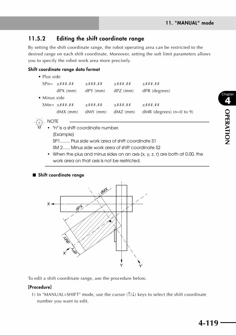
4-118 4-119
Chapter
4
OPER
ATIO
N
11. "MANUAL" mode
11.5.2 Editing the shift coordinate rangeBy setting the shift coordinate range, the robot operating area can be restricted to the
desired range on each shift coordinate. Moreover, setting the soft limit parameters allows
you to specify the robot work area more precisely.
Shift coordinate range data format
•Plusside
SPn= ±###.## ±###.## ±###.## ±###.##
dPX (mm) dPY (mm) dPZ (mm) dPR (degrees)
•Minusside
SMn= ±###.## ±###.## ±###.## ±###.##
dMX (mm) dMY (mm) dMZ (mm) dMR (degrees) (n=0 to 9)
n NOTE
• "n"isashiftcoordinatenumber.
[Example]
SP1........ Plus side work area of shift coordinate S1
SM 2...... Minus side work area of shift coordinate S2
• Whentheplusandminussidesonanaxis(x,y,z,r)arebothat0.00,the
work area on that axis is not be restricted.
■ Shift coordinate range
X
X’
Y Y’
dPX
dMX
dPY
dMY
To edit a shift coordinate range, use the procedure below.
[Procedure]
1) In "MANUAL>SHIFT" mode, use the cursor (↑/↓) keys to select the shift coordinate
number you want to edit.

4-120
Chapter
4
OPER
ATIO
N
4-121
11. "MANUAL" mode
2) Press (RANGE) to enter the "MANUAL>SHIFT>RANGE" mode.
A cursor for editing the shift coordinate range appears.
■ Editing shift coordinate range (1)
MANUAL>SHIFT>RANGE 50% [MG][S1H0X]
————————————x———————y———————z———————r———
Range of shift coorinate [mm/deg]
SP1 =_ 0.00 0.00 0.00 0.00
SM1 = 0.00 0.00 0.00 0.00
[POS] 150.00 0.00 0.00 0.00
UNDO
3) Use the cursor (←/→) keys to move the cursor to the position you want to change.
4) Use to , , , and to enter the point data.
Enter a space to separate between the data for x and y. The data input formats are as
follows.
•ToenterthedatainCartesiancoordinates("mm"units)
Enter a number consisting of an integer portion of up to 5 digits and having 2 or
less places below the decimal point.
±###.##, ±####.#, ±#####.
n NOTE
Enter point data for both X-axis and Y-axis. If omitted, "0" will be
automatically entered for that axis.
■ Editing shift coordinate range (2)
MANUAL>SHIFT>RANGE 50% [MG][S1H0X]
————————————x———————y———————z———————r———
Range of shift coorinate [mm/deg]
SP1 = 300.00 300.00
SM1 = 0.00 0.00 0.00 0.00
0.00 0.00
[POS] 150.00 0.00 0.00 0.00UNDO
5) Press , cursor up/down (↑/↓) keys or page up/down ( , ) keys to
finish the data input.
Press if you want to cancel the data input.
4-120 4-121
Chapter
4
OPER
ATIO
N
11. "MANUAL" mode
6) To continue editing the shift coordinate range on the minus side, repeat steps 3) to 5).
7) Press to quit editing and return to "MANUAL>SHIFT" mode.
n NOTE
The shift coordinate number selected when returning to "MANUAL>SHIFT"
mode is used as the shift coordinates for the currently selected robot group.
Valid keys and submenu descriptions for editing shift coordinates range are shown below.
Valid keys Menu Function
F1 UNDO Reverses the last data input and restores the preceding data.
11.5.2.1 Restoring a shift coordinate range
[Procedure]
1) During editing of shift coordinate range data, pressing (UNDO) reverses the
last data input and restores the preceding data.
This function is enabled only on lines that are not yet complete.
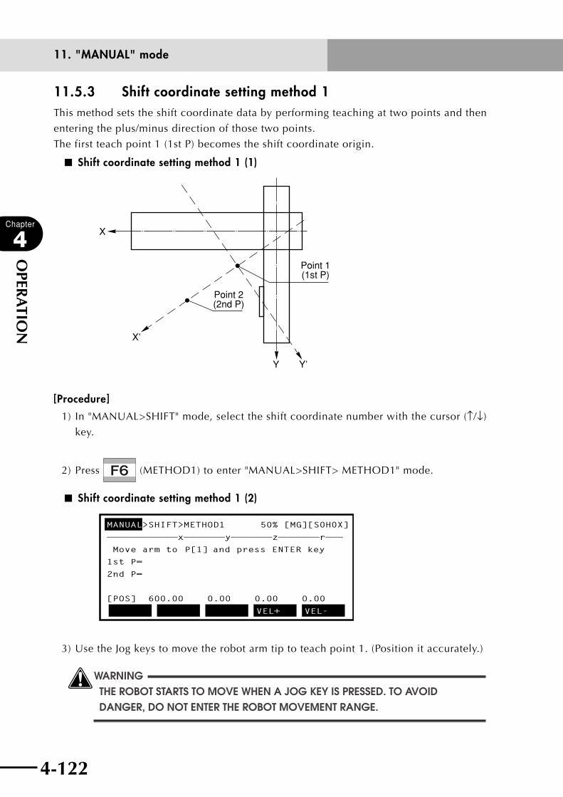
4-122
Chapter
4
OPER
ATIO
N
4-123
11. "MANUAL" mode
11.5.3 Shift coordinate setting method 1This method sets the shift coordinate data by performing teaching at two points and then
entering the plus/minus direction of those two points.
The first teach point 1 (1st P) becomes the shift coordinate origin.
■ Shift coordinate setting method 1 (1)
X
X’
Y Y’
Point 1(1st P)
Point 2(2nd P)
[Procedure]
1) In "MANUAL>SHIFT" mode, select the shift coordinate number with the cursor (↑/↓)
key.
2) Press (METHOD1) to enter "MANUAL>SHIFT> METHOD1" mode.
■ Shift coordinate setting method 1 (2)
MANUAL>SHIFT>METHOD1 50% [MG][S0H0X]
————————————x———————y———————z———————r———
Move arm to P[1] and press ENTER key
1st P=
2nd P=
[POS] 600.00 0.00 0.00 0.00
VEL+ VEL-
3) Use the Jog keys to move the robot arm tip to teach point 1. (Position it accurately.)
wWARNINGTHE ROBOT STARTS TO MOVE WHEN A jOG kEY IS PRESSED. TO AVOID DANGER, DO NOT ENTER THE ROBOT MOVEMENT RANGE.
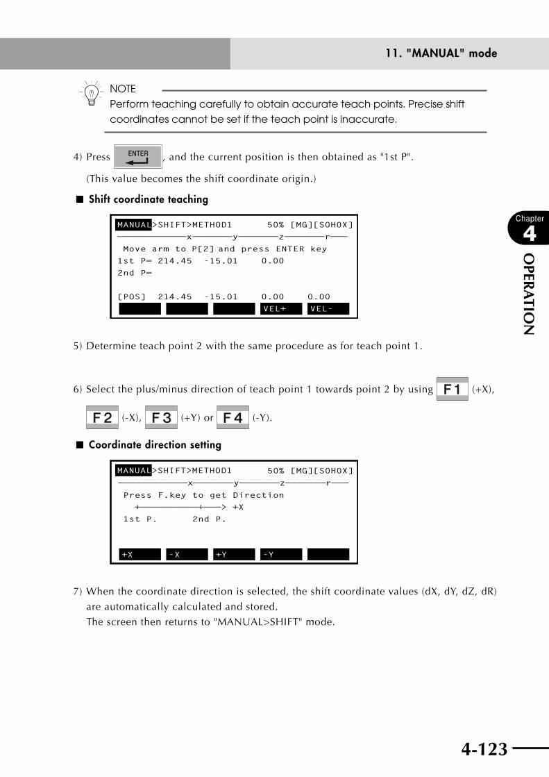
4-122 4-123
Chapter
4
OPER
ATIO
N
11. "MANUAL" mode
n NOTE
Perform teaching carefully to obtain accurate teach points. Precise shift
coordinates cannot be set if the teach point is inaccurate.
4) Press , and the current position is then obtained as "1st P".
(This value becomes the shift coordinate origin.)
■ Shift coordinate teaching
MANUAL>SHIFT>METHOD1 50% [MG][S0H0X]
————————————x———————y———————z———————r———
Move arm to P[2] and press ENTER key
1st P= 214.45 -15.01
2nd P=
[POS] 214.45 -15.01 0.000.00
0.00
VEL+ VEL-
5) Determine teach point 2 with the same procedure as for teach point 1.
6) Select the plus/minus direction of teach point 1 towards point 2 by using (+X),
(-X), (+Y) or (-Y).
■ Coordinate direction setting
MANUAL>SHIFT>METHOD1 50% [MG][S0H0X]
Press F.key to get Direction
+——————————+———> +X
1st P. 2nd P.
+X
+X -X +Y -Y
————————————x———————y———————z———————r———
7) When the coordinate direction is selected, the shift coordinate values (dX, dY, dZ, dR)
are automatically calculated and stored.
The screen then returns to "MANUAL>SHIFT" mode.

4-124
Chapter
4
OPER
ATIO
N
4-125
11. "MANUAL" mode
Valid keys and submenu descriptions in "MANUAL>SHIFT>METHOD1" mode are shown
below.
Valid keys Menu Function
F4 VEL+ Increases manual movement speed for the selected robot group in steps. (1→5→20→50→100%)
F5 VEL- Decreases manual movement speed for the selected robot group in steps. (100→50→20→5→1%)
F8 UNITCHG Switches between the current display units (mm or pulses).
F9 VEL++ Increases manual movement speed for the selected robot group in 1% increments.
F10 VEL-- Decreases manual movement speed for the selected robot group in 1% decrements.

4-124 4-125
Chapter
4
OPER
ATIO
N
11. "MANUAL" mode
11.5.4 Shift coordinate setting method 2This method sets the shift coordinate data by performing teaching at two points and then
entering the coordinate values of those two points.
■ Shift coordinate setting method 2 (1)
X
X’
YY’
P1
P2
[Procedure]
1) In "MANUAL>SHIFT" mode, select the shift coordinate number with the cursor (↑/↓)
key.
2) Press (METHOD2) to enter "MANUAL>SHIFT> METHOD2" mode.
■ Shift coordinate setting method 2 (2)
MANUAL>SHIFT>METHOD2 50% [MG][S0H0X]
————————————x———————y———————z———————r———
Move arm to P[1] and press ENTER key
1st P=
2nd P=
[POS] 600.00 0.00 0.00 0.00
VEL+ VEL-
3) Use the Jog keys to move the robot arm tip to teach point 1. (Position it accurately.)
wWARNINGTHE ROBOT STARTS TO MOVE WHEN A jOG kEY IS PRESSED. TO AVOID DANGER, DO NOT ENTER THE ROBOT MOVEMENT RANGE.

4-126
Chapter
4
OPER
ATIO
N
4-127
11. "MANUAL" mode
n NOTE
Perform teaching carefully to obtain accurate teach points. Precise shift
coordinates cannot be set if the teach point is inaccurate.
4) Press to obtain the current position as "1st P".
An edit cursor appears at the head of the "1st P" line.
■ Shift coordinate setting
MANUAL>SHIFT>METHOD2 50% [MG][S0H0X]
————————————x———————y———————z———————r———
Enter the point data [mm]
1st P=_ 0.00 0.00
2nd P=
[POS] 13.00 150.00 0.00 0.00
VEL+ VEL-
5) Use to , , , and to enter the point data (x, y, z) and
press .
n NOTE
Enter all point data (x, y, z) (x, y). If omitted, "0" will be automatically entered
for that axis.
cCAUTIONIf teach points and input points are not accurately determined, calculation results will be inaccurate, so always determine these points correctly.

4-126 4-127
Chapter
4
OPER
ATIO
N
11. "MANUAL" mode
6) Determine teach point 2 with the same procedure as for teach point 1.
n NOTE
The Z-direction shift value is automatically obtained when teach point 1 is
determined, so the Z-axis data at teach point 2 is ignored.
7) When the teach point 2 has been entered, the shift coordinates (dX, dY, dZ and dR)
are automatically calculated and stored.
The screen then returns to "MANUAL>SHIFT" mode.
Valid keys and submenu descriptions in "MANUAL>SHIFT>METHOD2" mode are shown
below.
Valid keys Menu Function
F4 VEL+ Increases manual movement speed for the selected robot group in steps. (1→5→20→50→100%)
F5 VEL- Decreases manual movement speed for the selected robot group in steps. (100→50→20→5→1%)
F8 UNITCHG Switches between the current display units (mm or pulses).
F9 VEL++ Increases manual movement speed for the selected robot group in 1% increments.
F10 VEL-- Decreases manual movement speed for the selected robot group in 1% decrements.
4-128
Chapter
4
OPER
ATIO
N
4-129
11. "MANUAL" mode
11.6 Displaying, editing and setting hand definitions
Press (HAND) in "MANUAL" mode to enter "MANUAL>HAND" mode. This mode
allows you to display, edit and set hand definitions. However, the standard coordinates
must be set when a SCARA robot is used. Refer to "11.9 Setting the standard coordinates"
for details.
Hand definitions cannot be used with MULTI type robots.
n NOTE
When two robots are specified, hand definitions data cannot be shared
between them. The main robot uses H0 - H3, and the sub robot H4 - H7 for
hand definition data.
n NOTE
Hand definition data cannot be used with MULTI type robots since the SHIFT/
HAND selection display on the 1st line on the RPB screen appears blank.
Four kinds of hand definitions can be set to change the robot working points with standard
coordinate settings to the working points of the hand installed to the 2nd arm (Y-axis) or
the R-axis.
This function allows movement using different hands towards point data in the same
Cartesian coordinate format.
• Data format for hand definition Hn= ±aaaaaa ±bbbbbb ±cccccc [R]
(main robot : n = 0 to 3 / sub robot : n = 4 to 7)
1st parameter................ ±aaaaaa
Enter a number consisting of an integer portion of up to 5
digits and having 2 or less places below the decimal point,
or an integer of up to 7 digits (depending on the robot type
setting and hand definition type).
2nd to 3rd parameters ... ±bbbbbb, ±cccccc
Enter a number consisting of an integer portion of up to 5
digits and having 2 or less places below the decimal point.
4th parameter ............... R
Enter one character (depending on the hand definition
type).
When all values for a hand definition are "0", this means the hand definition is not set.

4-128 4-129
Chapter
4
OPER
ATIO
N
11. "MANUAL" mode
When "MANUAL>HAND" mode is entered, a screen like that shown below appears.
The currently selected hand definition number is highlighted.
■ Hand definition screen
MANUAL>HAND 50% [MG][S0H1X]
————————————1———————2———————3———————4———
H0 = 0 0.00 0.00
H1 = 0.00 100.00 0.00 R
H2 = 90.00 100.00 100.00 R
H3 = 8000 100.00 100.00
[POS] 600.00 0.00 0.00 0.00EDIT VEL+ VEL-
Valid keys and submenu descriptions in "MANUAL>HAND" mode are shown below.
Valid keys Menu Function
Cursor key ( ↑ / ↓ ) Specifies the hand definition number.
F1 EDIT Edits the hand definition.
F4 VEL+ Increases manual movement speed for the selected robot group in steps. (1→5→20→50→100%)
F5 VEL- Decreases manual movement speed for the selected robot group in steps. (100→50→20→5→1%)
F6 METHOD1 Makes setting 1 for hand coordinates.
F8 UNITCHG Switches between the current display units (mm or pulses).
F9 VEL++ Increases manual movement speed for the selected robot group in 1% increments.
F10 VEL-- Decreases manual movement speed for the selected robot group in 1% decrements.
ROBOT
( + )Switches the robot group.
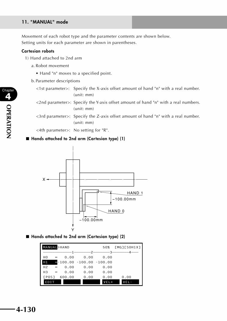
4-130
Chapter
4
OPER
ATIO
N
4-131
11. "MANUAL" mode
Movement of each robot type and the parameter contents are shown below.
Setting units for each parameter are shown in parentheses.
Cartesian robots
1) Hand attached to 2nd arm
a. Robot movement
•Hand"n"movestoaspecifiedpoint.
b. Parameter descriptions
<1st parameter>: Specify the X-axis offset amount of hand "n" with a real number.
(unit: mm)
<2nd parameter>: Specify the Y-axis offset amount of hand "n" with a real numbers.
(unit: mm)
<3rd parameter>: Specify the Z-axis offset amount of hand "n" with a real number.
(unit: mm)
<4th parameter>: No setting for "R".
■ Hands attached to 2nd arm (Cartesian type) (1)
Y
X
−100.00mm
−100.00mm
HAND 1
HAND 0
■ Hands attached to 2nd arm (Cartesian type) (2)
MANUAL>HAND 50% [MG][S0H1X]
————————————1———————2———————3———————4———
H0 = 0.00 0.00 0.00
H1 =-100.00 -100.00 -100.00
H2 = 0.00 0.00 0.00
H3 = 0.00 0.00 0.00
[POS] 600.00 0.00 0.00 0.00
EDIT VEL+ VEL-

4-130 4-131
Chapter
4
OPER
ATIO
N
11. "MANUAL" mode
11.6.1 Editing hand definitions
[Procedure]
1) Press (EDIT) in "MANUAL>HAND" mode.
2) Use the cursor (↑/↓) keys to select the hand definition you want to edit.
An edit cursor appears at the left end of the selected hand definition line.
■ Hand editing screen (1)
MANUAL>HAND>EDIT 50% [MG][S0H1X]
————————————1———————2———————3———————4———
H0 = 0 0.00 0.00
H1 =_ 0.00 100.00 0.00 R
H2 = 90.00 100.00 100.00 R
H3 = 8000 100.00 100.00
[POS] 600.00 0.00 0.00 0.00
UNDO
3) Use the cursor (←/→) key to move the cursor to the position you want to edit.
4) Use to , , , , , and to enter the data.
■ Hand editing screen (2)
MANUAL>HAND>EDIT 50% [MG][S0H1X]
————————————1———————2———————3———————4———
H0 = 0 0.00 0.00
H1 = 45.00 300 100 R_
H2 = 90.00 100.00 100.00 R
H3 = 8000 100.00 100.00
[POS] 600.00 0.00 0.00 0.00
UNDO
5) Pressing or cursor up/down (↑/↓) keys completes the hand definition
settings.
Press if you want to cancel the settings.
6) To continue editing, repeat steps 2) to 4).
4-132
Chapter
4
OPER
ATIO
N
4-133
11. "MANUAL" mode
7) Press to quit editing and return to "MANUAL>HAND" mode.
n NOTE
The hand definition data with which the cursor was positioned when
returning to "MANUAL>HAND" mode is used as the current hand definition.
Valid keys and submenu descriptions in "MANUAL>HAND>EDIT" mode are shown below.
Valid keys Menu Function
F1 UNDO Reverses the last data input and restores the preceding data.
11.6.1.1 Restoring hand definitions
[Procedure]
1) During hand definition editing, pressing (UNDO) reverses the last data input
and restores the preceding data.
This function is enabled only on lines that are not yet complete.
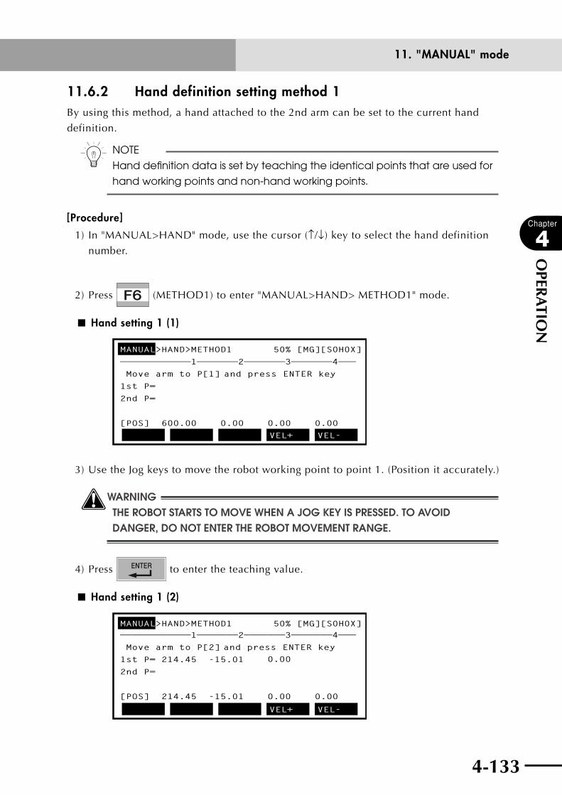
4-132 4-133
Chapter
4
OPER
ATIO
N
11. "MANUAL" mode
11.6.2 Hand definition setting method 1By using this method, a hand attached to the 2nd arm can be set to the current hand
definition.
n NOTE
Hand definition data is set by teaching the identical points that are used for
hand working points and non-hand working points.
[Procedure]
1) In "MANUAL>HAND" mode, use the cursor (↑/↓) key to select the hand definition
number.
2) Press (METHOD1) to enter "MANUAL>HAND> METHOD1" mode.
■ Hand setting 1 (1)
MANUAL>HAND>METHOD1 50% [MG][S0H0X]
————————————1———————2———————3———————4———
Move arm to P[1] and press ENTER key
1st P=
2nd P=
[POS] 600.00 0.00 0.00 0.00
VEL+ VEL-
3) Use the Jog keys to move the robot working point to point 1. (Position it accurately.)
wWARNINGTHE ROBOT STARTS TO MOVE WHEN A jOG kEY IS PRESSED. TO AVOID DANGER, DO NOT ENTER THE ROBOT MOVEMENT RANGE.
4) Press to enter the teaching value.
■ Hand setting 1 (2)
MANUAL>HAND>METHOD1 50% [MG][S0H0X]————————————1———————2———————3———————4———
Move arm to P[2] and press ENTER key
1st P= 214.45 -15.01
2nd P=
[POS] 214.45 -15.01 0.000.00
0.00
VEL+ VEL-
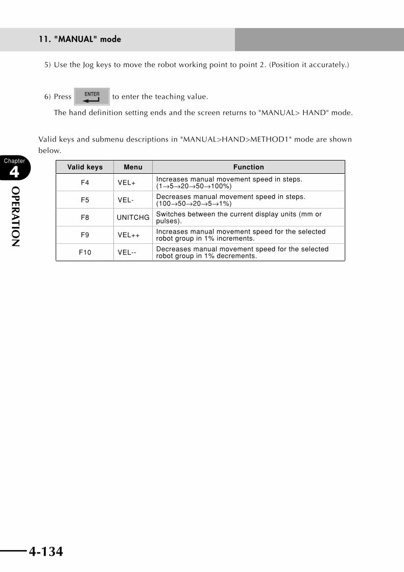
4-134
Chapter
4
OPER
ATIO
N
4-135
11. "MANUAL" mode
5) Use the Jog keys to move the robot working point to point 2. (Position it accurately.)
6) Press to enter the teaching value.
The hand definition setting ends and the screen returns to "MANUAL> HAND" mode.
Valid keys and submenu descriptions in "MANUAL>HAND>METHOD1" mode are shown
below.
Valid keys Menu Function
F4 VEL+ Increases manual movement speed in steps. (1→5→20→50→100%)
F5 VEL- Decreases manual movement speed in steps. (100→50→20→5→1%)
F8 UNITCHG Switches between the current display units (mm or pulses).
F9 VEL++ Increases manual movement speed for the selected robot group in 1% increments.
F10 VEL-- Decreases manual movement speed for the selected robot group in 1% decrements.
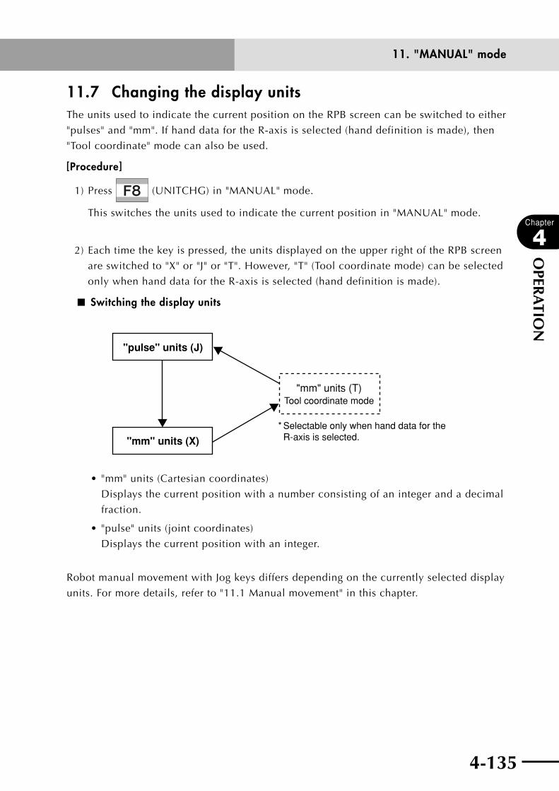
4-134 4-135
Chapter
4
OPER
ATIO
N
11. "MANUAL" mode
11.7 Changing the display unitsThe units used to indicate the current position on the RPB screen can be switched to either
"pulses" and "mm". If hand data for the R-axis is selected (hand definition is made), then
"Tool coordinate" mode can also be used.
[Procedure]
1) Press (UNITCHG) in "MANUAL" mode.
This switches the units used to indicate the current position in "MANUAL" mode.
2) Each time the key is pressed, the units displayed on the upper right of the RPB screen
are switched to "X" or "J" or "T". However, "T" (Tool coordinate mode) can be selected
only when hand data for the R-axis is selected (hand definition is made).
■ Switching the display units
"pulse" units (J)
"mm" units (X)
"mm" units (T)Tool coordinate mode
* Selectable only when hand data for the R-axis is selected.
•"mm"units(Cartesiancoordinates)
Displays the current position with a number consisting of an integer and a decimal
fraction.
•"pulse"units(jointcoordinates)
Displays the current position with an integer.
Robot manual movement with Jog keys differs depending on the currently selected display
units. For more details, refer to "11.1 Manual movement" in this chapter.
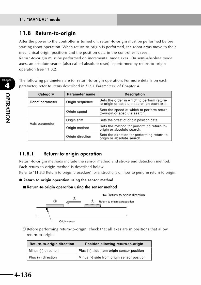
4-136
Chapter
4
OPER
ATIO
N
4-137
11. "MANUAL" mode
11.8 Return-to-originAfter the power to the controller is turned on, return-to-origin must be performed before
starting robot operation. When return-to-origin is performed, the robot arms move to their
mechanical origin positions and the position data in the controller is reset.
Return-to-origin must be performed on incremental mode axes. On semi-absolute mode
axes, an absolute search (also called absolute reset) is performed by return-to-origin
operation (see 11.8.2).
The following parameters are for return-to-origin operation. For more details on each
parameter, refer to items described in "12.1 Parameters" of Chapter 4.
Category Parameter name Description
Robot parameter Origin sequence Sets the order in which to perform return-to-origin or absolute search on each axis.
Axis parameter
Origin speed Sets the speed at which to perform return-to-origin or absolute search.
Origin shift Sets the offset of origin position data.
Origin method Sets the method for performing return-to-origin or absolute search.
Origin direction Sets the direction for performing return-to-origin or absolute search.
11.8.1 Return-to-originoperationReturn-to-origin methods include the sensor method and stroke end detection method.
Each return-to-origin method is described below.
Refer to "11.8.3 Return-to-origin procedure" for instructions on how to perform return-to-origin.
lReturn-to-originoperationusingthesensormethod
nReturn-to-originoperationusingthesensormethod
Return-to-origin direction
qew
Return-to-origin start position
Origin sensor
q Before performing return-to-origin, check that all axes are in positions that allow
return-to-origin.
Return-to-origin direction Position allowing return-to-origin
Minus (-) direction Plus (+) side from origin sensor position
Plus (+) direction Minus (-) side from origin sensor position
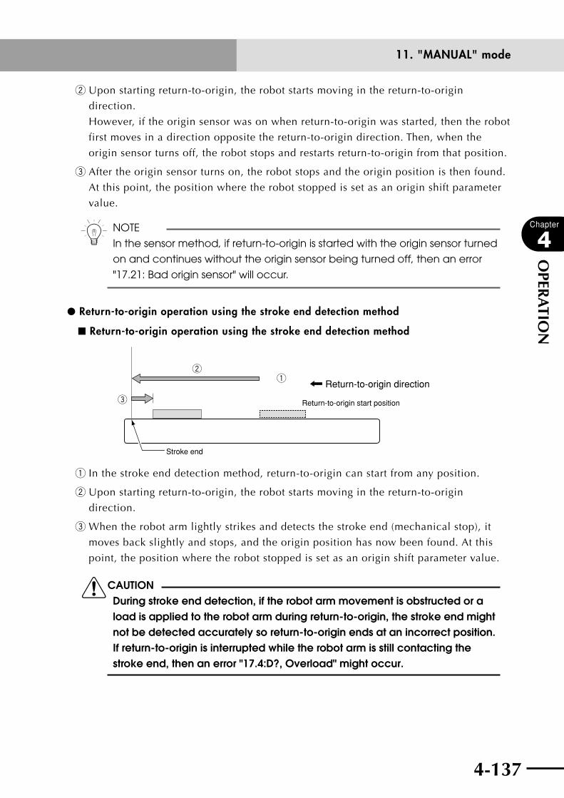
4-136 4-137
Chapter
4
OPER
ATIO
N
11. "MANUAL" mode
w Upon starting return-to-origin, the robot starts moving in the return-to-origin
direction.
However, if the origin sensor was on when return-to-origin was started, then the robot
first moves in a direction opposite the return-to-origin direction. Then, when the
origin sensor turns off, the robot stops and restarts return-to-origin from that position.
e After the origin sensor turns on, the robot stops and the origin position is then found.
At this point, the position where the robot stopped is set as an origin shift parameter
value.
n NOTE
In the sensor method, if return-to-origin is started with the origin sensor turned
on and continues without the origin sensor being turned off, then an error
"17.21: Bad origin sensor" will occur.
l Return-to-origin operation using the stroke end detection method
■ Return-to-origin operation using the stroke end detection method
Return-to-origin directionq
e
w
Return-to-origin start position
Stroke end
q In the stroke end detection method, return-to-origin can start from any position.
w Upon starting return-to-origin, the robot starts moving in the return-to-origin
direction.
e When the robot arm lightly strikes and detects the stroke end (mechanical stop), it
moves back slightly and stops, and the origin position has now been found. At this
point, the position where the robot stopped is set as an origin shift parameter value.
cCAUTIONDuring stroke end detection, if the robot arm movement is obstructed or a load is applied to the robot arm during return-to-origin, the stroke end might not be detected accurately so return-to-origin ends at an incorrect position. If return-to-origin is interrupted while the robot arm is still contacting the stroke end, then an error "17.4:D?, Overload" might occur.
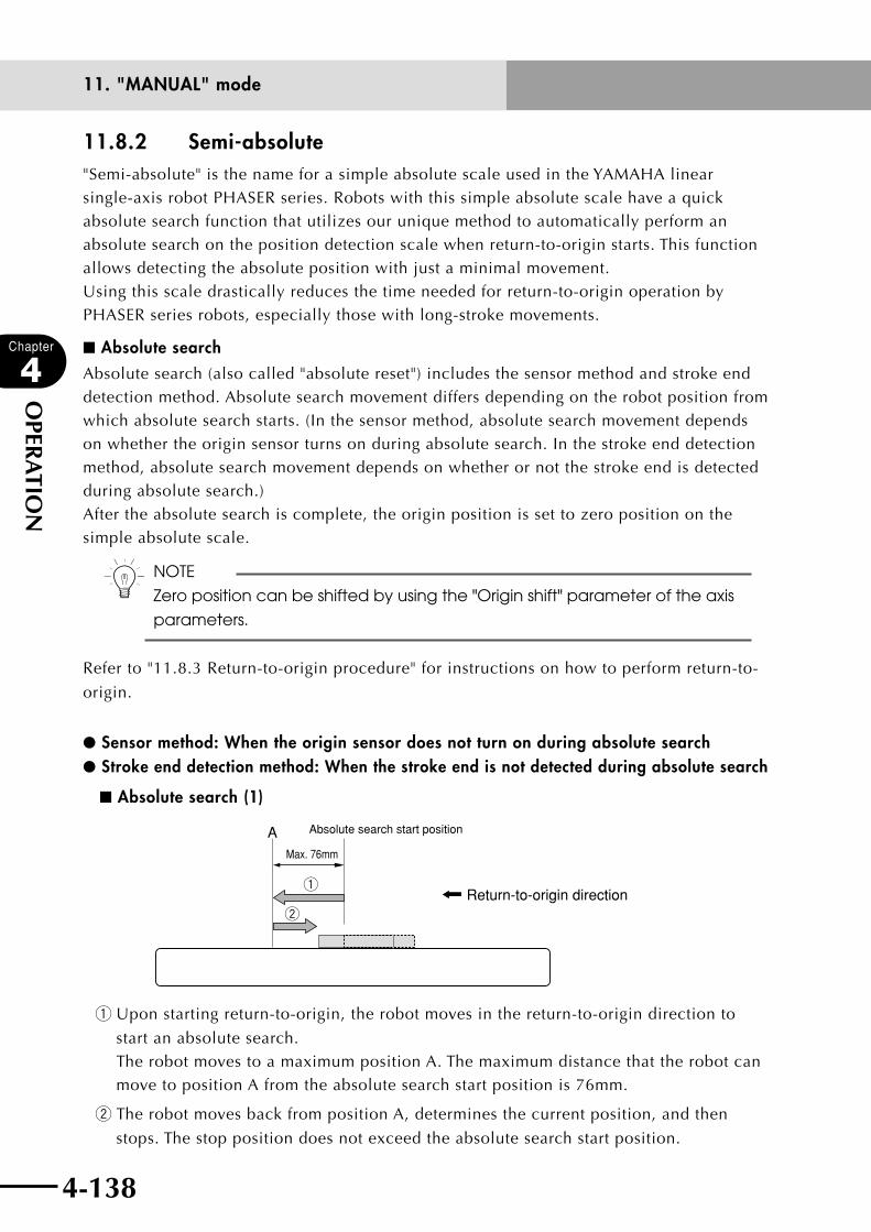
4-138
Chapter
4
OPER
ATIO
N
4-139
11. "MANUAL" mode
11.8.2 Semi-absolute"Semi-absolute" is the name for a simple absolute scale used in the YAMAHA linear single-axis robot PHASER series. Robots with this simple absolute scale have a quick absolute search function that utilizes our unique method to automatically perform an absolute search on the position detection scale when return-to-origin starts. This function allows detecting the absolute position with just a minimal movement.Using this scale drastically reduces the time needed for return-to-origin operation by PHASER series robots, especially those with long-stroke movements.
■Absolute searchAbsolute search (also called "absolute reset") includes the sensor method and stroke end detection method. Absolute search movement differs depending on the robot position from which absolute search starts. (In the sensor method, absolute search movement depends on whether the origin sensor turns on during absolute search. In the stroke end detection method, absolute search movement depends on whether or not the stroke end is detected during absolute search.)After the absolute search is complete, the origin position is set to zero position on the simple absolute scale.
n NOTE
Zero position can be shifted by using the "Origin shift" parameter of the axis
parameters.
Refer to "11.8.3 Return-to-origin procedure" for instructions on how to perform return-to-
origin.
lSensor method: When the origin sensor does not turn on during absolute searchlStroke end detection method: When the stroke end is not detected during absolute search
■Absolute search (1)
Absolute search start position
Return-to-origin directionq
w
AMax. 76mm
q Upon starting return-to-origin, the robot moves in the return-to-origin direction to
start an absolute search. The robot moves to a maximum position A. The maximum distance that the robot can move to position A from the absolute search start position is 76mm.
w The robot moves back from position A, determines the current position, and then
stops. The stop position does not exceed the absolute search start position.
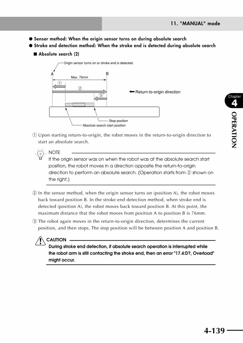
4-138 4-139
Chapter
4
OPER
ATIO
N
11. "MANUAL" mode
lSensor method: When the origin sensor turns on during absolute searchlStroke end detection method: When the stroke end is detected during absolute search
■ Absolute search (2)
Return-to-origin direction
A
Origin sensor turns on or stroke end is detected.
q
w
Max. 76mm
e
Absolute search start positionStop position
B
q Upon starting return-to-origin, the robot moves in the return-to-origin direction to
start an absolute search.
n NOTE
If the origin sensor was on when the robot was at the absolute search start
position, the robot moves in a direction opposite the return-to-origin
direction to perform an absolute search. (Operation starts from w shown on
the right.)
w In the sensor method, when the origin sensor turns on (position A), the robot moves
back toward position B. In the stroke end detection method, when stroke end is
detected (position A), the robot moves back toward position B. At this point, the
maximum distance that the robot moves from position A to position B is 76mm.
e The robot again moves in the return-to-origin direction, determines the current
position, and then stops. The stop position will be between position A and position B.
cCAUTIONDuring stroke end detection, if absolute search operation is interrupted while the robot arm is still contacting the stroke end, then an error "17.4:D?, Overload" might occur.
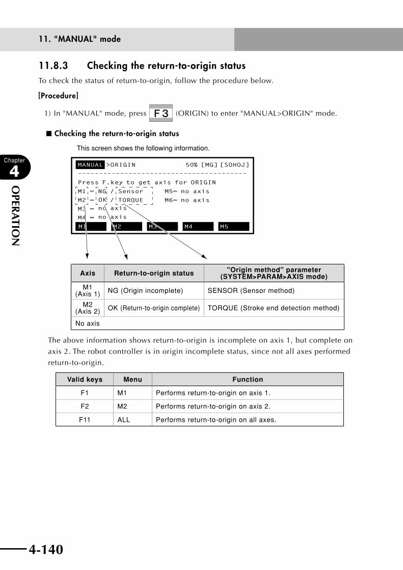
4-140
Chapter
4
OPER
ATIO
N
4-141
11. "MANUAL" mode
11.8.3 Checking the return-to-origin statusTo check the status of return-to-origin, follow the procedure below.
[Procedure]
1) In "MANUAL" mode, press (ORIGIN) to enter "MANUAL>ORIGIN" mode.
■ Checking the return-to-origin status
This screen shows the following information.
MANUAL >ORIGIN 50% [MG] [SOHOJ]
––––––––––––––––––––––––––––––––––––––––
Press F.key to get axis for ORIGIN
M1 = NG / Sensor M5= no axis
M2 = / TORQUE M6= no axis
M3 =
M4 =
M1 M2 M3 M4 M5
OK no axis
no axis
Axis Return-to-origin status "Origin method" parameter (SYSTEM>PARAM>AXIS mode)
M1 (Axis 1) NG (Origin incomplete) SENSOR (Sensor method)
M2 (Axis 2) OK (Return-to-origin complete) TORQUE (Stroke end detection method)
No axis
The above information shows return-to-origin is incomplete on axis 1, but complete on
axis 2. The robot controller is in origin incomplete status, since not all axes performed
return-to-origin.
Valid keys Menu Function
F1 M1 Performs return-to-origin on axis 1.
F2 M2 Performs return-to-origin on axis 2.
F11 ALL Performs return-to-origin on all axes.
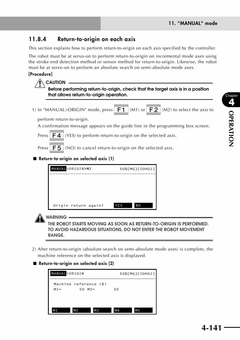
4-140 4-141
Chapter
4
OPER
ATIO
N
11. "MANUAL" mode
11.8.4 Return-to-origin on each axisThis section explains how to perform return-to-origin on each axis specified by the controller.
The robot must be at servo-on to perform return-to-origin on incremental mode axes using the stroke end detection method or sensor method for return-to-origin. Likewise, the robot must be at servo-on to perform an absolute search on semi-absolute mode axes.
[Procedure]
cCAUTIONBefore performing return-to-origin, check that the target axis is in a position that allows return-to-origin operation.
1) In "MANUAL>ORIGIN" mode, press (M1) or (M2) to select the axis to
perform return-to-origin.
A confirmation message appears on the guide line in the programming box screen.
Press (YES) to perform return-to-origin on the selected axis.
Press (NO) to cancel return-to-origin on the selected axis.
■ Return-to-origin on selected axis (1)
50%[MG][S0H0J]MANUAL>ORIGIN>M1 >M1
Origin return again? YES NO
wWARNINGTHE ROBOT STARTS MOVING AS SOON AS RETURN-TO-ORIGIN IS PERFORMED. TO AVOID HAzARDOUS SITUATIONS, DO NOT ENTER THE ROBOT MOVEMENT RANGE.
2) After return-to-origin (absolute search on semi-absolute mode axes) is complete, the machine reference on the selected axis is displayed.
■ Return-to-origin on selected axis (2)
50%[MG][S0H0J]MANUAL>ORIGIN
Machine reference (%)
M1= 50 M2= 50
M1 M2 M3 M4 M5

4-142
Chapter
4
OPER
ATIO
N
4-143
11. "MANUAL" mode
n NOTE
• Referto"11.8.1Return-to-originoperation"inChapter4fordetailson
return-to-origin operation, and refer to "11.8.2 Semi-absolute" for details
on absolute search operation.
• Themachinereferenceisexpressedasapercentageofthenumberof
encoder pulses showing the difference between the origin sensor signal
and position detector reference signal (encoder zero signal, etc.). This is
also called the "grid position" or "grid pulse".
3) When return-to-origin on all axes is complete, the dashed line (- - - -) on the message
line changes to a solid line ( ––––– ) indicating that return-to-origin is now complete.
Then, pressing an axis movement key displays the current position on each axis.
n NOTE
Once return-to-origin is completed, the origin position is retained until the
controller power is turned off or system parameters are changed. So it is not
necessary to re-perform return-to-origin even after using emergency stop.
4) To cancel the return-to-origin operation, press .
In this case, the message "0.14: Stop executed" appears on the message line.

4-142 4-143
Chapter
4
OPER
ATIO
N
11. "MANUAL" mode
11.8.5 Return-to-origin on all axesThis section explains how to perform return-to-origin on all axes specified by the controller.
The robot must be at servo-on to perform return-to-origin on incremental mode axes using the stroke end detection method or sensor method for return-to-origin. Likewise, the robot must be at servo-on to perform an absolute search on semi-absolute mode axes.
[Procedure]
cCAUTIONBefore performing return-to-origin, check that all axes are in positions that allow return-to-origin operation.
1) In "MANUAL>ORIGIN" mode, press (ALL) to perform return-to-origin on all axes.
A confirmation message appears on the guide line in the programming box screen.
Press (YES) to perform return-to-origin on all axes.
Press (NO) to cancel return-to-origin on all axes.
■ Return-to-origin on all axes (1)
50%[MG][S0H0J]MANUAL>ORIGIN>ALL
Origin return again? YES NO
wWARNINGTHE ROBOT STARTS MOVING AS SOON AS RETURN-TO-ORIGIN IS PERFORMED. TO AVOID HAzARDOUS SITUATIONS, DO NOT ENTER THE ROBOT MOVEMENT RANGE.
2) After return-to-origin (absolute search on semi-absolute mode axes) is complete, the machine references on all axes are displayed.
■ Return-to-origin on all axes (2)
50%[MG][S0H0J]MANUAL>ORIGIN
Machine reference (%)
M1= 50 M2= 50
M1 M2 M3 M4 M5

4-144
Chapter
4
OPER
ATIO
N
4-145
11. "MANUAL" mode
n NOTE
• Referto"11.8.1Return-to-originoperation"inChapter4fordetailson
return-to-origin operation, and refer to "11.8.2 Semi-absolute" for details
on absolute search operation.
• Themachinereferenceisexpressedasapercentageofthenumberof
encoder pulses showing the difference between the origin sensor signal
and position detector reference signal (encoder zero signal, etc.). This is
also called the "grid position" or "grid pulse".
3) When return-to-origin on all axes is complete, the dashed line (- - - -) on the message
line changes to a solid line ( ––––– ) indicating that return-to-origin is now complete.
Then, pressing an axis movement key displays the current position on each axis.
n NOTE
Once return-to-origin is completed, the origin position is retained until the
controller power is turned off or system parameters are changed. So it is not
necessary to re-perform return-to-origin even after using emergency stop.
4) To cancel the return-to-origin operation, press .
In this case, the message "0.14: Stop executed" appears on the message line.
4-144 4-145
Chapter
4
OPER
ATIO
N
11. "MANUAL" mode
11.9 Setting the standard coordinatesThe standard coordinates set for SCARA robots are treated as Cartesian coordinates using
the X-axis rotating center as the coordinate origin.
The following operations and functions are enabled on SCARA robots by setting the
standard coordinates.
n NOTE
On Cartesian type robots, there is no need to set the standard coordinates.
•Movingrobotarmtipatrightangles.
•Usingpalletdefinition,SHIFTcoordinatesandHANDdefinition.
•Usingcommandsrequiringcoordinateconversion(suchaslinear/circular
interpolation and pallet movement commands).
Special parameter setting is required to use this function. Consult us for assistance.

4-146
Chapter
4
OPER
ATIO
N
11. "MANUAL" mode
11.10 Executing the user function keysUser function keys allow you to perform various tasks easily when needed. For example,
assigning operation of an air-driven unit connected to an output port to a function key will
prove useful when performing point teaching in "MANUAL" mode.
n NOTE
• Whenusingtheuserfunctionkeys,itisnecessarytomakeaprogram
named "FUNCTION" and then write command statements for storing
functions.
• Whenregisteringthefunctionkeys,referto"10.3.9Creatingasample
program automatically" and "10.6 Registering user function keys" earlier in
this chapter.
[Procedure]
1) Press in "MANUAL" mode and the menus (character strings shown highlighted)
from to or to appear when assigned in advance.
Each character string is displayed in up to 7 characters from the beginning.
2) Press the desired function key and the preassigned task will be executed just as if
using online commands.
wWARNING• tHerobotstArtstoMovewHensoMecoMMAndsAreexecuted.to
AVOID DANGER, DO NOT ENTER THE ROBOT MOVEMENT RANGE.• robotMoveMentcoMMAndsAreexecutedAt"Auto"Modespeed
RATHER THAN "MANUAL" MODE SPEED.
■ Executing the user function keys
MANUAL>POINT 50%[MG][S0H0X]
————————————x———————y———————z———————r———
P7 = 100.00 250.00
P8 =
P9 = 122.62 -24.54
DO(20)A1 DO(21)A DO(22)A DO(23)A DO(24)A
COMNT : [ ]
[POS] 50.00 100.00 0.00 0.00
0.00 0.00
0.00 0.00

4-147
Chapter
4
OPER
ATIO
N
12. "SYSTEM" mode
12. "SYSTEM" mode The "SYSTEM" mode controls all kinds of operating conditions for the overall robot system.
The initial "SYSTEM" mode screen is shown below.
■ "SYSTEM" mode screen
qMode hierarchy eMessage linewVersion display
t Robot model name
r Online command execution mark
y Axis configuration
u Standard system configuration
i Other expanded configurations
o Guideline
SYSTEM V9.00
Robot = TXYx-A
Axes = XYZR
Standard = SRAM/364kB
Opt-i/f = DIO_N(1/2)
PARAM CMU OPTION INIT DIAGNOS
@
q Mode hierarchy
Shows the current mode hierarchy. When the highest mode (in this case "SYSTEM") is
highlighted it means the servomotor power is on. When not highlighted it means the
servomotor power is off.
w Version display
Shows the version number of software currently installed in the robot controller.
e Message line
If an error occurs, the error message appears here.
r Online command execution mark
When an online command is being executed, a "@" mark appears in the second
column on the second line. This mark changes to a dot "." when the online command
ends.
t Robot model name
Shows the robot model name specified by the controller.
When two robots (main robot and sub robot) are specified, their model names appear
separated by a slash "/".
y Axis configuration
Shows the axis configuration of the robot connected to the controller.
When two robots (main robot and sub robot) are specified, their axis configurations
appear separated by a slash "/".
u Standard system configuration
Shows the memory type and size.
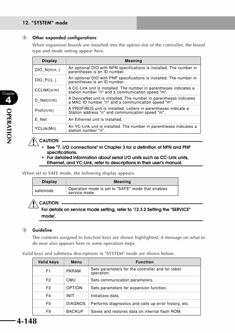
4-148
Chapter
4
OPER
ATIO
N
4-149
12. "SYSTEM" mode
i Other expanded configurations
When expansion boards are installed into the option slot of the controller, the board type and mode setting appear here.
Display Meaning
DIO_N(m/n..) An optional DIO with NPN specifications is installed. The number in parentheses is an ID number.
DIO_P(i/j..) An optional DIO with PNP specifications is installed. The number in parentheses is an ID number.
CCLNK(n/m) A CC-Link unit is installed. The number in parentheses indicates a station number "n" and a communication speed "m".
D_Net(n/m) A DeviceNet unit is installed. The number in parentheses indicates a MAC ID number "n" and a communication speed "m".
Profi(n/m) A PROFIBUS unit is installed. Letters in parentheses indicate a Station address "n" and communication speed "m".
E_Net An Ethernet unit is installed.
YCLnk(Mn) An YC-Link unit is installed. The number in parentheses indicates a station number "n".
cCAUTION• see"7.i/oconnections"inchapter3foradefinitionofnpnandpnp
specifications.• fordetailedinformationaboutseriali/ounitssuchascc-linkunits,
Ethernet, and YC-Link, refer to descriptions in their user's manual.
When set to SAFE mode, the following display appears.
Display Meaning
safemode Operation mode is set to "SAFE" mode that enables service mode.
cCAUTIONFor details on service mode setting, refer to '12.3.2 Setting the "SERVICE" mode'.
o Guideline
The contents assigned to function keys are shown highlighted. A message on what to do next also appears here in some operation steps.
Valid keys and submenu descriptions in "SYSTEM" mode are shown below.
Valid keys Menu Function
F1 PARAM Sets parameters for the controller and for robot operation.
F2 CMU Sets communication parameters.
F3 OPTION Sets parameters for expansion function.
F4 INIT Initializes data.
F5 DIAGNOS Performs diagnostics and calls up error history, etc.
F9 BACKUP Saves and restores data on internal flash ROM.
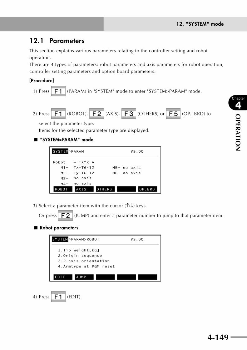
4-148 4-149
Chapter
4
OPER
ATIO
N
12. "SYSTEM" mode
12.1 ParametersThis section explains various parameters relating to the controller setting and robot
operation.
There are 4 types of parameters: robot parameters and axis parameters for robot operation,
controller setting parameters and option board parameters.
[Procedure]
1) Press (PARAM) in "SYSTEM" mode to enter "SYSTEM>PARAM" mode.
2) Press (ROBOT), (AXIS), (OTHERS) or (OP. BRD) to
select the parameter type.
Items for the selected parameter type are displayed.
■ "SYSTEM>PARAM" mode
SYSTEM>PARAM V9.00
Robot = TXYx-A
M1= Tx-T6-12 M5= no axis
M2= Ty-T6-12 M6= no axis
M3=
M4=
ROBOT AXIS OTHERS OP.BRD
no axis
no axis
3) Select a parameter item with the cursor (↑/↓) keys.
Or press (JUMP) and enter a parameter number to jump to that parameter item.
■ Robot parameters
SYSTEM>PARAM>ROBOT V9.00
1.Tip weight[kg]
2.Origin sequence
4.Armtype at PGM reset
3.R axis orientation
EDIT JUMP
4) Press (EDIT).
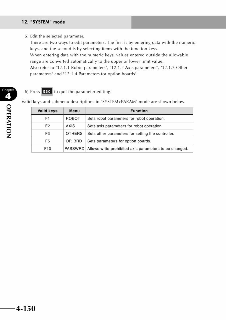
4-150
Chapter
4
OPER
ATIO
N
4-151
12. "SYSTEM" mode
5) Edit the selected parameter.
There are two ways to edit parameters. The first is by entering data with the numeric
keys, and the second is by selecting items with the function keys.
When entering data with the numeric keys, values entered outside the allowable
range are converted automatically to the upper or lower limit value.
Also refer to "12.1.1 Robot parameters", "12.1.2 Axis parameters", "12.1.3 Other
parameters" and "12.1.4 Parameters for option boards".
6) Press to quit the parameter editing.
Valid keys and submenu descriptions in "SYSTEM>PARAM" mode are shown below.
Valid keys Menu Function
F1 ROBOT Sets robot parameters for robot operation.
F2 AXIS Sets axis parameters for robot operation.
F3 OTHERS Sets other parameters for setting the controller.
F5 OP. BRD Sets parameters for option boards.
F10 PASSWRD Allows write-prohibited axis parameters to be changed.
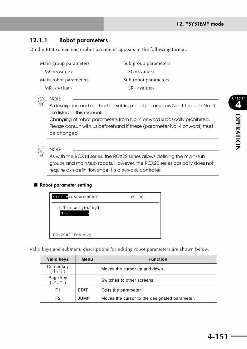
4-150 4-151
Chapter
4
OPER
ATIO
N
12. "SYSTEM" mode
12.1.1 Robot parametersOn the RPB screen each robot parameter appears in the following format.
Main group parameters Sub group parameters
MG=<value> SG=<value>
Main robot parameters Sub robot parameters
MR=<value> SR=<value>
n NOTE
A description and method for setting robot parameters No. 1 through No. 3
are listed in this manual.
Changing of robot parameters from No. 4 onward is basically prohibited.
Please consult with us beforehand if these (parameter No. 4 onward) must
be changed.
n NOTE
As with the RCX14 series, the RCX22 series allows defining the main/sub
groups and main/sub robots. However, the RCX22 series basically does not
require axis definition since it is a two-axis controller.
■ Robot parameter setting
SYSTEM>PARAM>ROBOT V9.00
1.Tip weight[kg]
MR= 5
[0-200] Enter>5_
Valid keys and submenu descriptions for editing robot parameters are shown below.
Valid keys Menu Function
Cursor key ( ↑ / ↓ ) Moves the cursor up and down.
Page key (
〈〈 / 〈〈 ) Switches to other screens.
F1 EDIT Edits the parameter.
F2 JUMP Moves the cursor to the designated parameter.
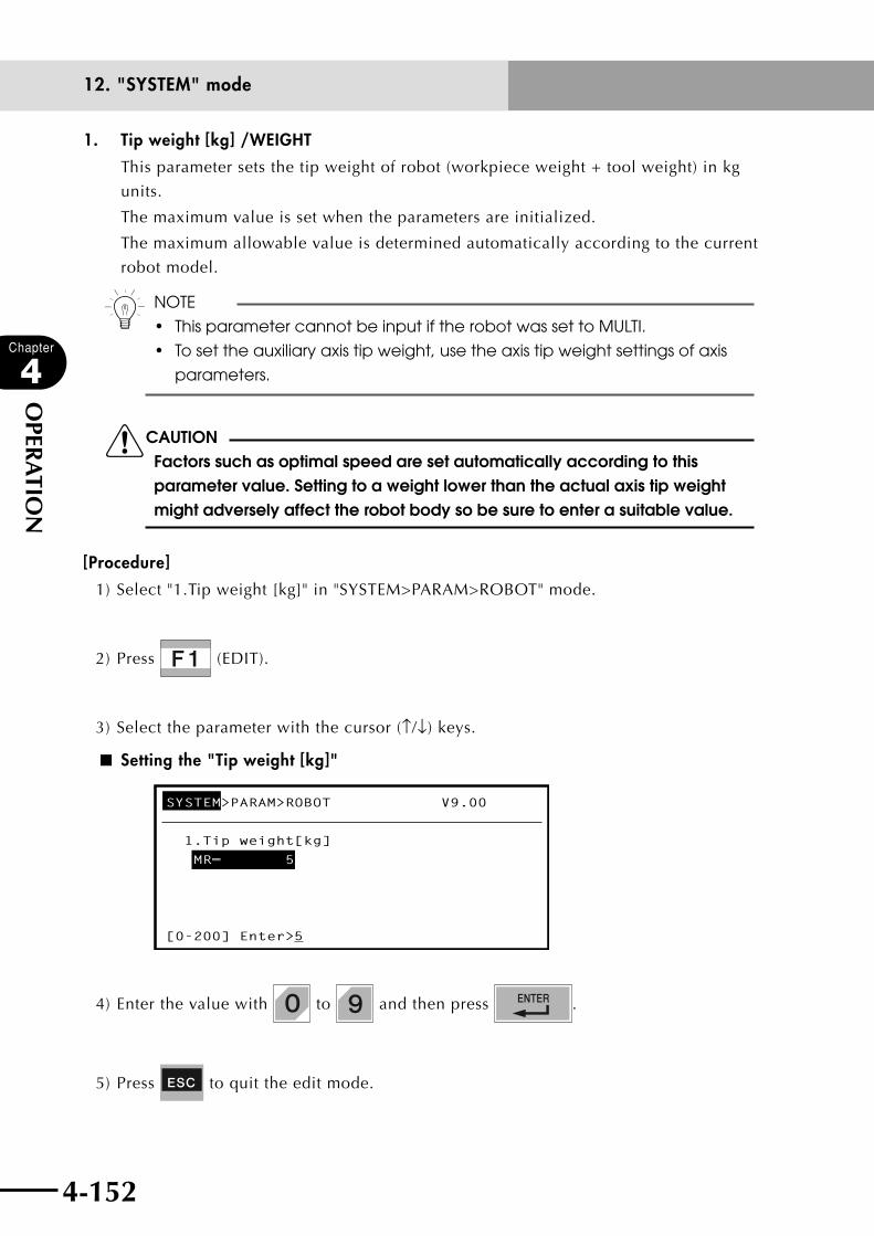
4-152
Chapter
4
OPER
ATIO
N
4-153
12. "SYSTEM" mode
1. Tip weight [kg] /WEIGHT
This parameter sets the tip weight of robot (workpiece weight + tool weight) in kg
units.
The maximum value is set when the parameters are initialized.
The maximum allowable value is determined automatically according to the current
robot model.
n NOTE
• ThisparametercannotbeinputiftherobotwassettoMULTI.
• Tosettheauxiliaryaxistipweight,usetheaxistipweightsettingsofaxis
parameters.
cCAUTIONFactors such as optimal speed are set automatically according to this parameter value. Setting to a weight lower than the actual axis tip weight might adversely affect the robot body so be sure to enter a suitable value.
[Procedure]
1) Select "1.Tip weight [kg]" in "SYSTEM>PARAM>ROBOT" mode.
2) Press (EDIT).
3) Select the parameter with the cursor (↑/↓) keys.
■ Setting the "Tip weight [kg]"
SYSTEM>PARAM>ROBOT V9.00
1.Tip weight[kg]
MR= 5
[0-200] Enter>_5
4) Enter the value with to and then press .
5) Press to quit the edit mode.
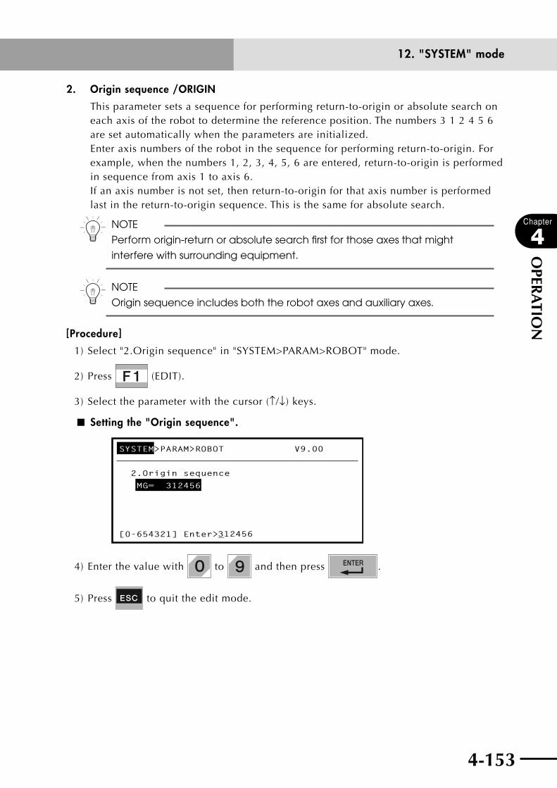
4-152 4-153
Chapter
4
OPER
ATIO
N
12. "SYSTEM" mode
2. Origin sequence /ORIGIN
This parameter sets a sequence for performing return-to-origin or absolute search on each axis of the robot to determine the reference position. The numbers 3 1 2 4 5 6 are set automatically when the parameters are initialized. Enter axis numbers of the robot in the sequence for performing return-to-origin. For example, when the numbers 1, 2, 3, 4, 5, 6 are entered, return-to-origin is performed in sequence from axis 1 to axis 6. If an axis number is not set, then return-to-origin for that axis number is performed last in the return-to-origin sequence. This is the same for absolute search.
n NOTE
Perform origin-return or absolute search first for those axes that might
interfere with surrounding equipment.
n NOTE
Origin sequence includes both the robot axes and auxiliary axes.
[Procedure]
1) Select "2.Origin sequence" in "SYSTEM>PARAM>ROBOT" mode.
2) Press (EDIT).
3) Select the parameter with the cursor (↑/↓) keys.
■ Setting the "Origin sequence".
SYSTEM>PARAM>ROBOT V9.00
2.Origin sequence
MG= 312456
312456[0-654321] Enter>_
4) Enter the value with to and then press .
5) Press to quit the edit mode.
4-154
Chapter
4
OPER
ATIO
N
4-155
12. "SYSTEM" mode
3. R-axis orientation /RORIEN
On SCARA robots, this parameter sets whether or not to maintain the R-axis direction
(orientation) when moving manually across the XY axes. The R direction (orientation)
is automatically set when the parameters are initialized.
If the R-axis direction has been set (held) and the arm tip is moved in the X or Y
directions, the R-axis automatically rotates to maintain its direction.
This is effective only on SCARA robots.
n NOTE
This parameter is valid only on SCARA robots.
n NOTE
This function is invalid if there is no R-axis or the R-axis is an auxiliary axis.

4-154 4-155
Chapter
4
OPER
ATIO
N
12. "SYSTEM" mode
12.1.2 Axis parametersEach axis parameter is displayed in the following format on the RPB screen.
Main robot axis setting Sub robot axis setting
M?=<value> S?=<value>
Main auxiliary axis setting Sub auxiliary axis setting
m?=<value> s?=<value>
n NOTE
A description and method for setting axis parameters No. 1 through No. 16
are listed in this manual.
Changing of parameters from No. 17 onward is basically prohibited. Please
consult with us beforehand if these (parameter No. 17 onward) must be
changed.
n NOTE
As with the RCX14 series, the RCX22 series allows defining the main/sub
groups and main/sub robots. However, the RCX22 series basically does not
require axis definition since it is a two-axis controller.
■ Axis parameter setting
SYSTEM>PARAM>AXIS V9.00
1.Accel coefficient[%]
M1= 100 M2= 100
[1-100] Enter>_100
Valid keys and submenu descriptions for editing robot parameters are shown below.
Valid keys Menu Function
Cursor key ( ↑ / ↓ ) Moves the cursor up and down.
Page key (
〈〈 / 〈〈 ) Scrolls up and down the screen.
F1 EDIT Edits the parameter.
F2 JUMP Moves the cursor to the designated parameter.
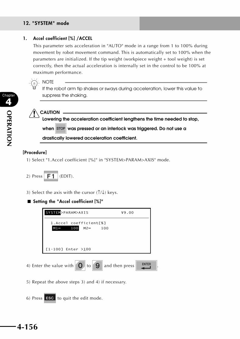
4-156
Chapter
4
OPER
ATIO
N
4-157
12. "SYSTEM" mode
1. Accel coefficient [%] /ACCEL
This parameter sets acceleration in "AUTO" mode in a range from 1 to 100% during
movement by robot movement command. This is automatically set to 100% when the
parameters are initialized. If the tip weight (workpiece weight + tool weight) is set
correctly, then the actual acceleration is internally set in the control to be 100% at
maximum performance.
n NOTE
If the robot arm tip shakes or sways during acceleration, lower this value to
suppress the shaking.
cCAUTIONLowering the acceleration coefficient lengthens the time needed to stop,
when was pressed or an interlock was triggered. Do not use a
drastically lowered acceleration coefficient.
[Procedure]
1) Select "1.Accel coefficient [%]" in "SYSTEM>PARAM>AXIS" mode.
2) Press (EDIT).
3) Select the axis with the cursor (↑/↓) keys.
■ Setting the "Accel coefficient [%]"
SYSTEM>PARAM>AXIS V9.00
1.Accel coefficient[%]
M1= 100 M2= 100
[1-100] Enter >_100
4) Enter the value with to and then press .
5) Repeat the above steps 3) and 4) if necessary.
6) Press to quit the edit mode.
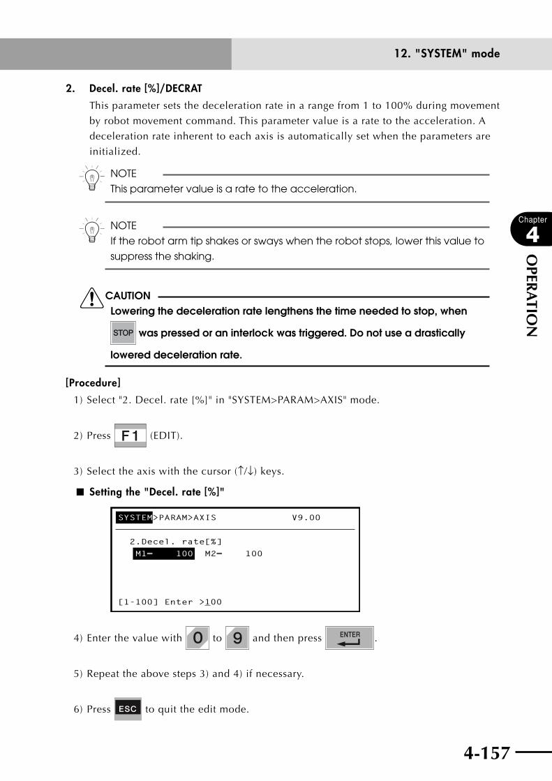
4-156 4-157
Chapter
4
OPER
ATIO
N
12. "SYSTEM" mode
2. Decel. rate [%]/DECRAT
This parameter sets the deceleration rate in a range from 1 to 100% during movement
by robot movement command. This parameter value is a rate to the acceleration. A
deceleration rate inherent to each axis is automatically set when the parameters are
initialized.
n NOTE
This parameter value is a rate to the acceleration.
n NOTE
If the robot arm tip shakes or sways when the robot stops, lower this value to
suppress the shaking.
cCAUTIONLowering the deceleration rate lengthens the time needed to stop, when
was pressed or an interlock was triggered. Do not use a drastically
lowered deceleration rate.
[Procedure]
1) Select "2. Decel. rate [%]" in "SYSTEM>PARAM>AXIS" mode.
2) Press (EDIT).
3) Select the axis with the cursor (↑/↓) keys.
■ Setting the "Decel. rate [%]"
SYSTEM>PARAM>AXIS V9.00
2.Decel. rate[%]
M1= 100 M2= 100
[1-100] Enter >_100
4) Enter the value with to and then press .
5) Repeat the above steps 3) and 4) if necessary.
6) Press to quit the edit mode.
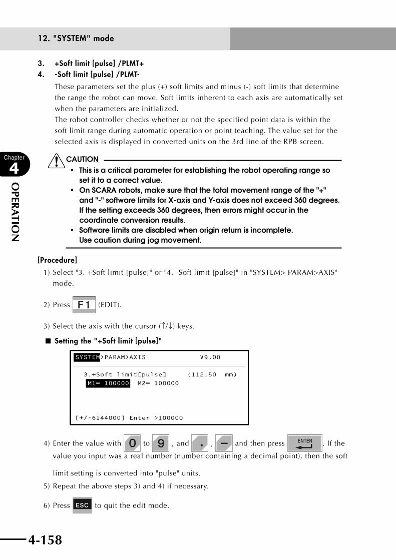
4-158
Chapter
4
OPER
ATIO
N
4-159
12. "SYSTEM" mode
3. +Soft limit [pulse] /PLMT+ 4. -Soft limit [pulse] /PLMT-
These parameters set the plus (+) soft limits and minus (-) soft limits that determine
the range the robot can move. Soft limits inherent to each axis are automatically set
when the parameters are initialized.
The robot controller checks whether or not the specified point data is within the
soft limit range during automatic operation or point teaching. The value set for the
selected axis is displayed in converted units on the 3rd line of the RPB screen.
cCAUTION• thisisacriticalparameterforestablishingtherobotoperatingrangeso
set it to a correct value.• onscArArobots,makesurethatthetotalmovementrangeofthe"+"
and "-" software limits for X-axis and Y-axis does not exceed 360 degrees. If the setting exceeds 360 degrees, then errors might occur in the coordinate conversion results.
• softwarelimitsaredisabledwhenoriginreturnisincomplete. Use caution during jog movement.
[Procedure]
1) Select "3. +Soft limit [pulse]" or "4. -Soft limit [pulse]" in "SYSTEM> PARAM>AXIS"
mode.
2) Press (EDIT).
3) Select the axis with the cursor (↑/↓) keys.
■ Setting the "+Soft limit [pulse]"
SYSTEM>PARAM>AXIS V9.00
3.+Soft limit[pulse] (112.50 mm)
M1= 100000 M2= 100000
[+/-6144000] Enter >_100000
4) Enter the value with to , and , and then press . If the
value you input was a real number (number containing a decimal point), then the soft
limit setting is converted into "pulse" units.
5) Repeat the above steps 3) and 4) if necessary.
6) Press to quit the edit mode.

4-158 4-159
Chapter
4
OPER
ATIO
N
12. "SYSTEM" mode
5. Tolerance [pulse] /TOLE
This parameter sets the tolerance range of the target position where robot movement ends. This is set to a value unique to each axis when initialized. Positioning on an axis is judged to be complete when the robot axis enters within the specified tolerance range. During consecutive PTP movement in a program, the larger this value is made, the more the positioning time can be shortened. The tolerance range set for the selected axis is displayed in converted units on the 3rd line of the RPB screen.
cCAUTION• thisisacriticalparameterfordeterminingtherobotmovementnearthe
target position so set it to a correct value.• ifthetolerancerangewasreducedtoadrasticallysmallvalue,thenthe
time needed for robot positioning might vary.• themaximumtolerancevalueisdeterminedbythemotor.
■ Tolerance range
Current position Target position
Tolerance range
[Procedure]
1) Select "5. Tolerance [pulse]" in "SYSTEM>PARAM>AXIS" mode.
2) Press (EDIT).
3) Select the axis with the cursor (↑/↓) keys.
■ Setting the "Tolerance [pulse]"
SYSTEM>PARAM>AXIS V9.00
5.Tolerance[pulse]
M1= 80 M2= 80
[1- ] Enter >_80
( 0. 09mm)
4) Enter the value with to , and and then press . If the value
you input was a real number (number containing a decimal point), then the tolerance
range is converted into "pulse" units.
4-160
Chapter
4
OPER
ATIO
N
4-161
12. "SYSTEM" mode
5) Repeat the above steps 3) and 4) if necessary.
6) Press to quit the edit mode.
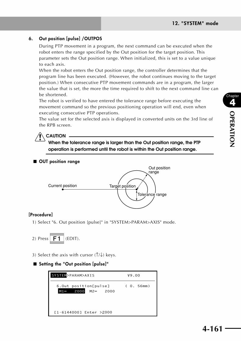
4-160 4-161
Chapter
4
OPER
ATIO
N
12. "SYSTEM" mode
6. Out position [pulse] /OUTPOS
During PTP movement in a program, the next command can be executed when the robot enters the range specified by the Out position for the target position. This parameter sets the Out position range. When initialized, this is set to a value unique to each axis. When the robot enters the Out position range, the controller determines that the program line has been executed. (However, the robot continues moving to the target position.) When consecutive PTP movement commands are in a program, the larger the value that is set, the more the time required to shift to the next command line can be shortened. The robot is verified to have entered the tolerance range before executing the movement command so the previous positioning operation will end, even when executing consecutive PTP operations. The value set for the selected axis is displayed in converted units on the 3rd line of the RPB screen.
cCAUTIONWhen the tolerance range is larger than the Out position range, the PTP operation is performed until the robot is within the Out position range.
■ OUT position range
Current position
Out position range
Target position
Tolerance range
[Procedure]
1) Select "6. Out position [pulse]" in "SYSTEM>PARAM>AXIS" mode.
2) Press (EDIT).
3) Select the axis with cursor (↑/↓) keys.
■ Setting the "Out position [pulse]"
SYSTEM>PARAM>AXIS V9.00
6.Out position[pulse] ( 0. 56mm)
M1= 2000 M2= 2000
[1-6144000] Enter >_2000

4-162
Chapter
4
OPER
ATIO
N
4-163
12. "SYSTEM" mode
4) Enter the value with to , and and then press . If the value
you input was a real number (number containing a decimal point), then it is converted
into pulse units.
5) Repeat the above steps 3) and 4) if necessary.
6) Press to quit the edit mode.

4-162 4-163
Chapter
4
OPER
ATIO
N
12. "SYSTEM" mode
7. Arch position [pulse] /ARCH
When an arch motion command (optional PTP operation) is executed, arch movement
begins when the robot enters the arch position range set by this parameter for the
target position. This parameter is set to a value unique to each axis when initialized.
When the axis specified for arch movement starts PTP movement toward the specified
position and enters the arch position range, the other axes start to move. When those
axes enter the arch position range, the arch-specified axis moves by PTP toward the
target position. Movement time can be shortened by making this value larger since
there is a greater overlap for axis operation.
The value set for the selected axis is displayed in converted units on the 3rd line of
the RPB screen.
cCAUTION• thearch-specifiedaxismaysometimesreachthetargetpositionfaster
than the other axes if the arch position is large. So set an accurate value for the arch position.
• Movementmaybealongdifferentpathsduringarchoperationduetothemovement speed. Check the arch motion at a speed at which the robot actually moves.
■ Arch motion
Current position Target position
Movement of other axes
Specified axis movement
Specified axis movement
Arch position range of arch-specified axis
Arch position range of other axes
[Procedure]
1) Select "7. Arch position [pulse]" in "SYSTEM>PARAM>AXIS" mode.
2) Press (EDIT).

4-164
Chapter
4
OPER
ATIO
N
4-165
12. "SYSTEM" mode
3) Select the axis with cursor (↑/↓) keys.
■ Setting the "Arch position [pulse]"
SYSTEM>PARAM>AXIS V9.00
7.Arch position[pulse] ( 0. 56mm)
M1= 2000 M2= 2000
[1-6144000] Enter >_2000
4) Enter the value with to , and and then press . If the value
you input was a real number (number containing a decimal point), then it is converted
into pulse units.
5) Repeat the above steps 3) and 4) if necessary.
6) Press to quit the edit mode.
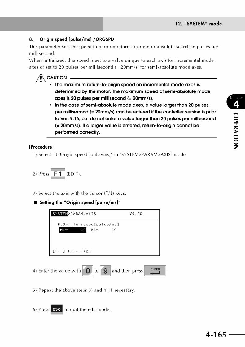
4-164 4-165
Chapter
4
OPER
ATIO
N
12. "SYSTEM" mode
8. Origin speed [pulse/ms] /ORGSPDThis parameter sets the speed to perform return-to-origin or absolute search in pulses per
millisecond.
When initialized, this speed is set to a value unique to each axis for incremental mode
axes or set to 20 pulses per millisecond (= 20mm/s) for semi-absolute mode axes.
cCAUTION• themaximumreturn-to-originspeedonincrementalmodeaxesis
determined by the motor. The maximum speed of semi-absolute mode axes is 20 pulses per millisecond (= 20mm/s).
• inthecaseofsemi-absolutemodeaxes,avaluelargerthan20pulsesper millisecond (= 20mm/s) can be entered if the controller version is prior to Ver. 9.16, but do not enter a value larger than 20 pulses per millisecond (= 20mm/s). If a larger value is entered, return-to-origin cannot be performed correctly.
[Procedure]
1) Select "8. Origin speed [pulse/ms]" in "SYSTEM>PARAM>AXIS" mode.
2) Press (EDIT).
3) Select the axis with the cursor (↑/↓) keys.
■ Setting the "Origin speed [pulse/ms]"
SYSTEM>PARAM>AXIS V9.00
8.Origin speed[pulse/ms]
M1= 20 M2= 20
[1- ] Enter >_20
4) Enter the value with to and then press .
5) Repeat the above steps 3) and 4) if necessary.
6) Press to quit the edit mode.

4-166
Chapter
4
OPER
ATIO
N
4-167
12. "SYSTEM" mode
9. Manual accel [%] /MANACC
This parameter sets the acceleration in a range from 1 to 100% during robot manual
movement. The manual acceleration is automatically set to 100 when the parameters
are initialized.
If the tip weight (workpiece weight + tool weight) is set correctly, then the actual
acceleration is automatically determined internally in the controller to obtain
optimum performance at 100%
n NOTE
If the robot arm tip shakes or sways during manual movement acceleration,
lower this value to suppress the shaking.
cCAUTIONLowering the acceleration coefficient lengthens the time needed to stop,
when was pressed or an interlock was triggered. Do not use a
drastically lowered acceleration coefficient.
[Procedure]
1) Select "9. Manual accel [%]" in "SYSTEM>PARAM>AXIS" mode.
2) Press (EDIT).
3) Select the axis with the cursor (↑/↓) keys.
■ Setting the "Manual accel [%]"
SYSTEM>PARAM>AXIS V9.00
9.Manual accel[%]
M1= 100 M2= 100
100
[1-100] Enter >_100
4) Input the value with to and then press .
5) Repeat the above steps 3) and 4) if necessary.
6) Press to quit the edit mode.

4-166 4-167
Chapter
4
OPER
ATIO
N
12. "SYSTEM" mode
10. Origin shift [pulse] /SHIFT
This parameter is used to correct the origin position error when the motor has been
replaced for some reason or the robot origin position has shifted due to mechanical
shocks. This parameter is set to 0 when initialized.
To correct the origin position error, enter the number of pulses required to move the
origin back to the correct position.
For example, if the B pulses represent the origin position that the robot arm moved
to after position error, and the A pulses are the origin position before position error,
then enter a value of "A - B",
cCAUTION• originshiftisacriticalparameterfordeterminingtherobotpositionsoset
it to a correct value. Change this parameter only when necessary.• originreturnwillbeincompleteifthisparameterischanged.• thisparameterisenabledafterperformingreturn-to-origin.
[Procedure]
1) Select "10. Origin shift [pulse]" in "SYSTEM>PARAM>AXIS" mode.
2) Press (EDIT).
3) Select the axis with the cursor (↑/↓) keys.
■ Setting the "Origin shift [pulse]"
SYSTEM>PARAM>AXIS V9.00
10.Origin shift[pulse]
M1= 0 M2= 0
[+/-6144000] Enter >_ 0
4) Enter the value with to , and then press .
5) Repeat the above steps 3) and 4) if necessary.
6) Press to quit the edit mode.
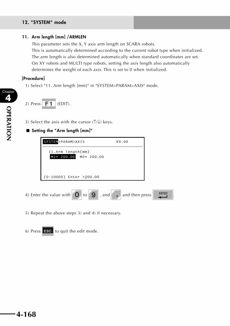
4-168
Chapter
4
OPER
ATIO
N
4-169
12. "SYSTEM" mode
11. Arm length [mm] /ARMLEN
This parameter sets the X, Y axis arm length on SCARA robots.
This is automatically determined according to the current robot type when initialized.
The arm length is also determined automatically when standard coordinates are set.
On XY robots and MULTI type robots, setting the axis length also automatically
determines the weight of each axis. This is set to 0 when initialized.
[Procedure]
1) Select "11. Arm length [mm]" in "SYSTEM>PARAM>AXIS" mode.
2) Press (EDIT).
3) Select the axis with the cursor (↑/↓) keys.
■ Setting the "Arm length [mm]"
SYSTEM>PARAM>AXIS V9.00
11.Arm length[mm]
M1= 200.00 M2= 200.00
[0-10000] Enter >_200.00
4) Enter the value with to , and and then press .
5) Repeat the above steps 3) and 4) if necessary.
6) Press to quit the edit mode.
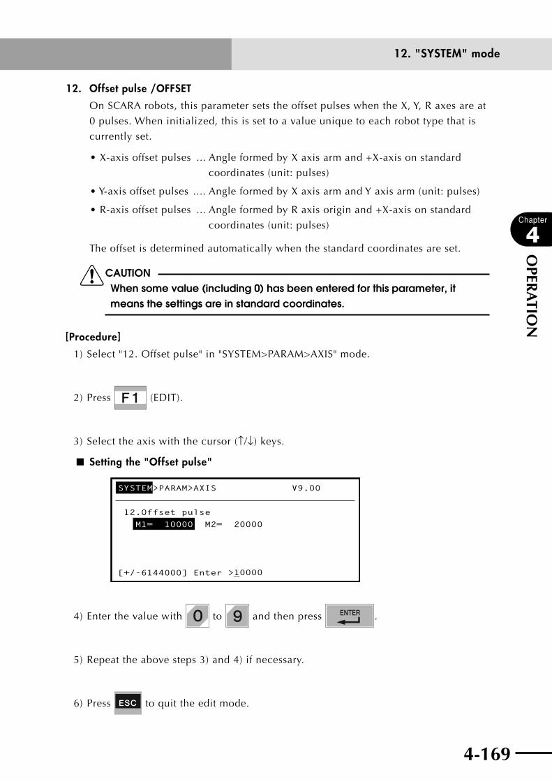
4-168 4-169
Chapter
4
OPER
ATIO
N
12. "SYSTEM" mode
12. Offset pulse /OFFSET
On SCARA robots, this parameter sets the offset pulses when the X, Y, R axes are at
0 pulses. When initialized, this is set to a value unique to each robot type that is
currently set.
•X-axisoffsetpulses ... Angle formed by X axis arm and +X-axis on standard
coordinates (unit: pulses)
•Y-axisoffsetpulses .... Angle formed by X axis arm and Y axis arm (unit: pulses)
•R-axisoffsetpulses ... Angle formed by R axis origin and +X-axis on standard
coordinates (unit: pulses)
The offset is determined automatically when the standard coordinates are set.
cCAUTIONWhen some value (including 0) has been entered for this parameter, it means the settings are in standard coordinates.
[Procedure]
1) Select "12. Offset pulse" in "SYSTEM>PARAM>AXIS" mode.
2) Press (EDIT).
3) Select the axis with the cursor (↑/↓) keys.
■ Setting the "Offset pulse"
SYSTEM>PARAM>AXIS V9.00
12.Offset pulse
M1= 10000 M2= 20000
[+/-6144000] Enter >_10000
4) Enter the value with to and then press .
5) Repeat the above steps 3) and 4) if necessary.
6) Press to quit the edit mode.

4-170
Chapter
4
OPER
ATIO
N
4-171
12. "SYSTEM" mode
13. Axis tip weight [kg] /AXSTIP
This parameter sets the weight of each axis tip (workpiece weight + tool weight) in
kilogram units on MULTI type robots. A maximum value is set when the parameters
are initialized.
The maximum weight is automatically determined according to the currently used
axis type.
n NOTE
• ThisparametercanbeenteredonlyforMULTItyperobots.
• ForrobotsotherthanMULTItyperobots,settherobotarmtipweight.
cCAUTIONOptimal acceleration and other items are automatically set according to this parameter value. The robot body may therefore be adversely affected if set to a lower value than the actual axis tip weight, so be sure to enter a correct value.
[Procedure]
1) Select "13. Axis tip weight [kg]" in "SYSTEM>PARAM>AXIS" mode.
2) Press (EDIT).
3) Select the axis with the cursor (↑/↓) keys.
■ Setting the "Axis tip weight [kg]"
SYSTEM>PARAM>AXIS V9.00
13.Axis tip weight[kg]
M1= 0 M2= 0
[0-200] Enter >_0
4) Enter the value with to and then press .
5) Repeat the above steps 3) and 4) if necessary.
6) Press to quit the edit mode.
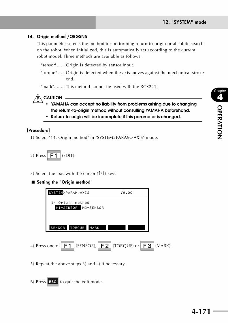
4-170 4-171
Chapter
4
OPER
ATIO
N
12. "SYSTEM" mode
14. Origin method /ORGSNS
This parameter selects the method for performing return-to-origin or absolute search
on the robot. When initialized, this is automatically set according to the current
robot model. Three methods are available as follows:
"sensor" ...... Origin is detected by sensor input.
"torque" ..... Origin is detected when the axis moves against the mechanical stroke
end.
"mark" ........ This method cannot be used with the RCX221.
cCAUTION• YAMAHAcanacceptnoliabilityfromproblemsarisingduetochanging
the return-to-origin method without consulting YAMAHA beforehand.• return-to-originwillbeincompleteifthisparameterischanged.
[Procedure]
1) Select "14. Origin method" in "SYSTEM>PARAM>AXIS" mode.
2) Press (EDIT).
3) Select the axis with the cursor (↑/↓) keys.
■ Setting the "Origin method"
SYSTEM>PARAM>AXIS V9.00
14.Origin method
M1=SENSOR M2=SENSOR
SENSOR TORQUE MARK
4) Press one of (SENSOR), (TORQUE) or (MARK).
5) Repeat the above steps 3) and 4) if necessary.
6) Press to quit the edit mode.
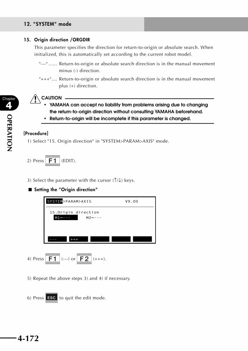
4-172
Chapter
4
OPER
ATIO
N
4-173
12. "SYSTEM" mode
15. Origin direction /ORGDIR
This parameter specifies the direction for return-to-origin or absolute search. When
initialized, this is automatically set according to the current robot model.
"---" ...... Return-to-origin or absolute search direction is in the manual movement
minus (-) direction.
"+++" .... Return-to-origin or absolute search direction is in the manual movement
plus (+) direction.
cCAUTION• YAMAHAcanacceptnoliabilityfromproblemsarisingduetochanging
the return-to-origin direction without consulting YAMAHA beforehand.• return-to-originwillbeincompleteifthisparameterischanged.
[Procedure]
1) Select "15. Origin direction" in "SYSTEM>PARAM>AXIS" mode.
2) Press (EDIT).
3) Select the parameter with the cursor (↑/↓) keys.
■ Setting the "Origin direction"
SYSTEM>PARAM>AXIS V9.00
15.Origin direction
M1=––– M2=–––
––– +++
4) Press (---) or (+++).
5) Repeat the above steps 3) and 4) if necessary.
6) Press to quit the edit mode.
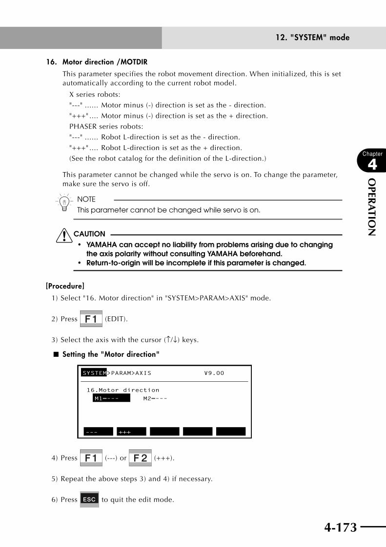
4-172 4-173
Chapter
4
OPER
ATIO
N
12. "SYSTEM" mode
16. Motor direction /MOTDIR
This parameter specifies the robot movement direction. When initialized, this is set automatically according to the current robot model.
X series robots:
"---" ...... Motor minus (-) direction is set as the - direction.
"+++" .... Motor minus (-) direction is set as the + direction.
PHASER series robots:
"---" ...... Robot L-direction is set as the - direction.
"+++" .... Robot L-direction is set as the + direction.
(See the robot catalog for the definition of the L-direction.)
This parameter cannot be changed while the servo is on. To change the parameter, make sure the servo is off.
n NOTE
This parameter cannot be changed while servo is on.
cCAUTION• YAMAHAcanacceptnoliabilityfromproblemsarisingduetochanging
the axis polarity without consulting YAMAHA beforehand.• return-to-origin will be incomplete if this parameter is changed.
[Procedure]
1) Select "16. Motor direction" in "SYSTEM>PARAM>AXIS" mode.
2) Press (EDIT).
3) Select the axis with the cursor (↑/↓) keys.
■ Setting the "Motor direction"
SYSTEM>PARAM>AXIS V9.00
16.Motor direction
M1=––– M2=–––
––– +++
4) Press (---) or (+++).
5) Repeat the above steps 3) and 4) if necessary.
6) Press to quit the edit mode.
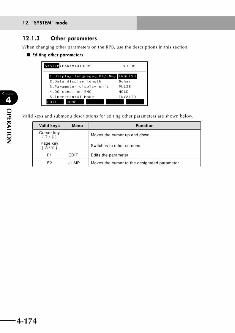
4-174
Chapter
4
OPER
ATIO
N
4-175
12. "SYSTEM" mode
12.1.3 Other parametersWhen changing other parameters on the RPB, use the descriptions in this section.
■ Editing other parameters
SYSTEM>PARAM>OTHERS V9.08
1.Display language(JPN/ENG) ENGLISH
2.Data display length 6char
3.Parameter display unit PULSE
4.DO cond. on EMG HOLD
5.Incremental Mode INVALID
EDIT JUMP
Valid keys and submenu descriptions for editing other parameters are shown below.
Valid keys Menu Function
Cursor key ( ↑ / ↓ ) Moves the cursor up and down.
Page key (
〈〈 / 〈〈 ) Switches to other screens.
F1 EDIT Edits the parameter.
F2 JUMP Moves the cursor to the designated parameter.
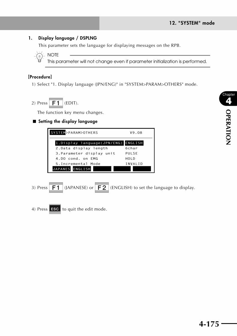
4-174 4-175
Chapter
4
OPER
ATIO
N
12. "SYSTEM" mode
1. Display language / DSPLNG
This parameter sets the language for displaying messages on the RPB.
n NOTE
This parameter will not change even if parameter initialization is performed.
[Procedure]
1) Select "1. Display language (JPN/ENG)" in "SYSTEM>PARAM>OTHERS" mode.
2) Press (EDIT).
The function key menu changes.
■ Setting the display language
SYSTEM>PARAM>OTHERS V9.08
1.Display language(JPN/ENG) ENGLISH
2.Data display length 6char
3.Parameter display unit PULSE
4.DO cond. on EMG HOLD
5.Incremental Mode INVALID
JAPANES ENGLISH
3) Press (JAPANESE) or (ENGLISH) to set the language to display.
4) Press to quit the edit mode.
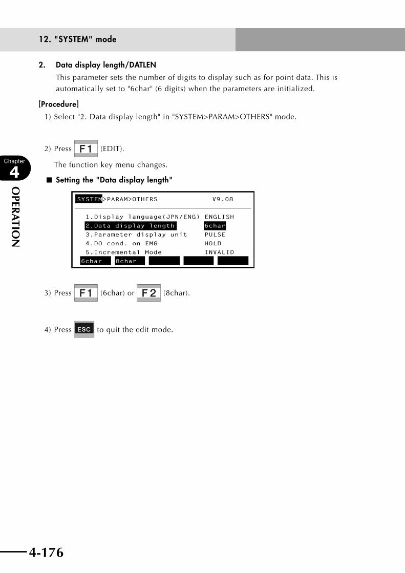
4-176
Chapter
4
OPER
ATIO
N
4-177
12. "SYSTEM" mode
2. Data display length/DATLEN
This parameter sets the number of digits to display such as for point data. This is
automatically set to "6char" (6 digits) when the parameters are initialized.
[Procedure]
1) Select "2. Data display length" in "SYSTEM>PARAM>OTHERS" mode.
2) Press (EDIT).
The function key menu changes.
■ Setting the "Data display length"
SYSTEM>PARAM>OTHERS V9.08
1.Display language(JPN/ENG) ENGLISH
2.Data display length 6char
3.Parameter display unit PULSE
4.DO cond. on EMG HOLD
5.Incremental Mode INVALID
6char 8char
3) Press (6char) or (8char).
4) Press to quit the edit mode.
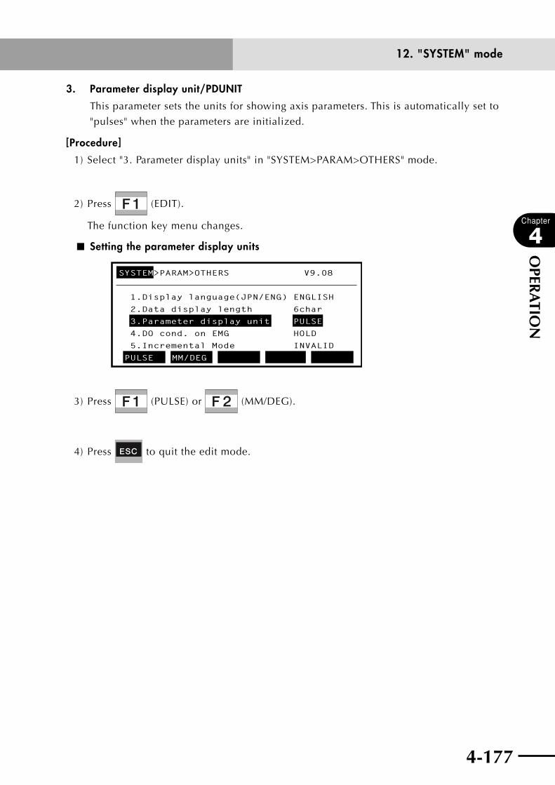
4-176 4-177
Chapter
4
OPER
ATIO
N
12. "SYSTEM" mode
3. Parameter display unit/PDUNIT
This parameter sets the units for showing axis parameters. This is automatically set to
"pulses" when the parameters are initialized.
[Procedure]
1) Select "3. Parameter display units" in "SYSTEM>PARAM>OTHERS" mode.
2) Press (EDIT).
The function key menu changes.
■ Setting the parameter display units
SYSTEM>PARAM>OTHERS V9.08
1.Display language(JPN/ENG) ENGLISH
2.Data display length 6char
3.Parameter display unit PULSE
4.DO cond. on EMG HOLD
5.Incremental Mode INVALID
PULSE MM/DEG
3) Press (PULSE) or (MM/DEG).
4) Press to quit the edit mode.
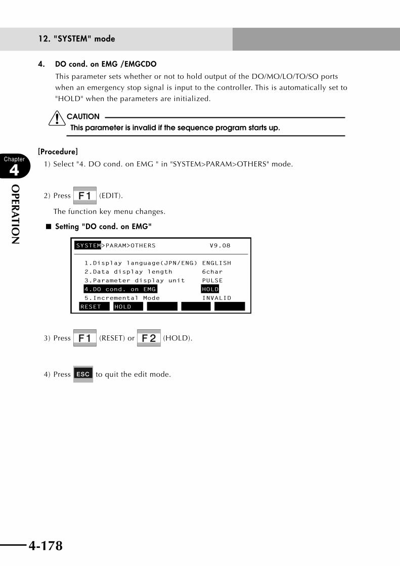
4-178
Chapter
4
OPER
ATIO
N
4-179
12. "SYSTEM" mode
4. DO cond. on EMG /EMGCDO
This parameter sets whether or not to hold output of the DO/MO/LO/TO/SO ports
when an emergency stop signal is input to the controller. This is automatically set to
"HOLD" when the parameters are initialized.
cCAUTIONThis parameter is invalid if the sequence program starts up.
[Procedure]
1) Select "4. DO cond. on EMG " in "SYSTEM>PARAM>OTHERS" mode.
2) Press (EDIT).
The function key menu changes.
■ Setting "DO cond. on EMG"
SYSTEM>PARAM>OTHERS V9.08
1.Display language(JPN/ENG) ENGLISH
2.Data display length 6char
3.Parameter display unit PULSE
4.DO cond. on EMG HOLD
5.Incremental Mode INVALID
RESET HOLD
3) Press (RESET) or (HOLD).
4) Press to quit the edit mode.
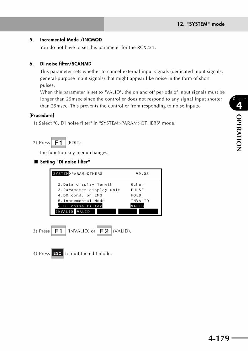
4-178 4-179
Chapter
4
OPER
ATIO
N
12. "SYSTEM" mode
5. Incremental Mode /INCMOD
You do not have to set this parameter for the RCX221.
6. DI noise filter/SCANMD
This parameter sets whether to cancel external input signals (dedicated input signals,
general-purpose input signals) that might appear like noise in the form of short
pulses.
When this parameter is set to "VALID", the on and off periods of input signals must be
longer than 25msec since the controller does not respond to any signal input shorter
than 25msec. This prevents the controller from responding to noise inputs.
[Procedure]
1) Select "6. DI noise filter" in "SYSTEM>PARAM>OTHERS" mode.
2) Press (EDIT).
The function key menu changes.
■ Setting "DI noise filter"
SYSTEM>PARAM>OTHERS V9.08
INVALID VALID
2.Data display length 6char
3.Parameter display unit PULSE
4.DO cond. on EMG HOLD
5.Incremental Mode INVALID
6.DI noise filter VALID
3) Press (INVALID) or (VALID).
4) Press to quit the edit mode.

4-180
Chapter
4
OPER
ATIO
N
4-181
12. "SYSTEM" mode
7. TRUE condition / EXPCFG
This parameter selects the operation when the conditional expression, which is used
for the STOPON option in an IF (including ELSEIF), WHILE to WEND, WAIT, MOVE,
or DRIVE statement, is a numeric expression.
This parameter is set to "-1" when the parameters are initialized.
n NOTE
This parameter is supported by controllers of Ver. 9.08 onwards.
[Procedure]
1) Select "7. TRUE condition" in "SYSTEM>PARAM>OTHERS" mode.
2) Press (EDIT).
The function key menu changes.
■ Setting "TRUE condition"
SYSTEM>PARAM>OTHERS V9.08
−1 not 0
3.Parameter display unit PULSE
4.DO cond. on EMG HOLD
5.Incremental Mode INVALID
6.DI noise filter VALID
7.TRUE condition -1
3) Press (-1) or (not 0) to change the setting.
Setting Meaning
-1 (default setting)
When conditional expression is a numeric expression, the
result is "TRUE" if the expression value is -1, and is "FALSE"
if 0. If the value is other than -1 and 0, an error "6.35:
EXPRESSION ERROR" occurs.
not 0
When conditional expression is a numeric expression, the
result is "TRUE" if the expression value is other than 0, and is
"FALSE" if 0.
4) Press to quit the edit mode.
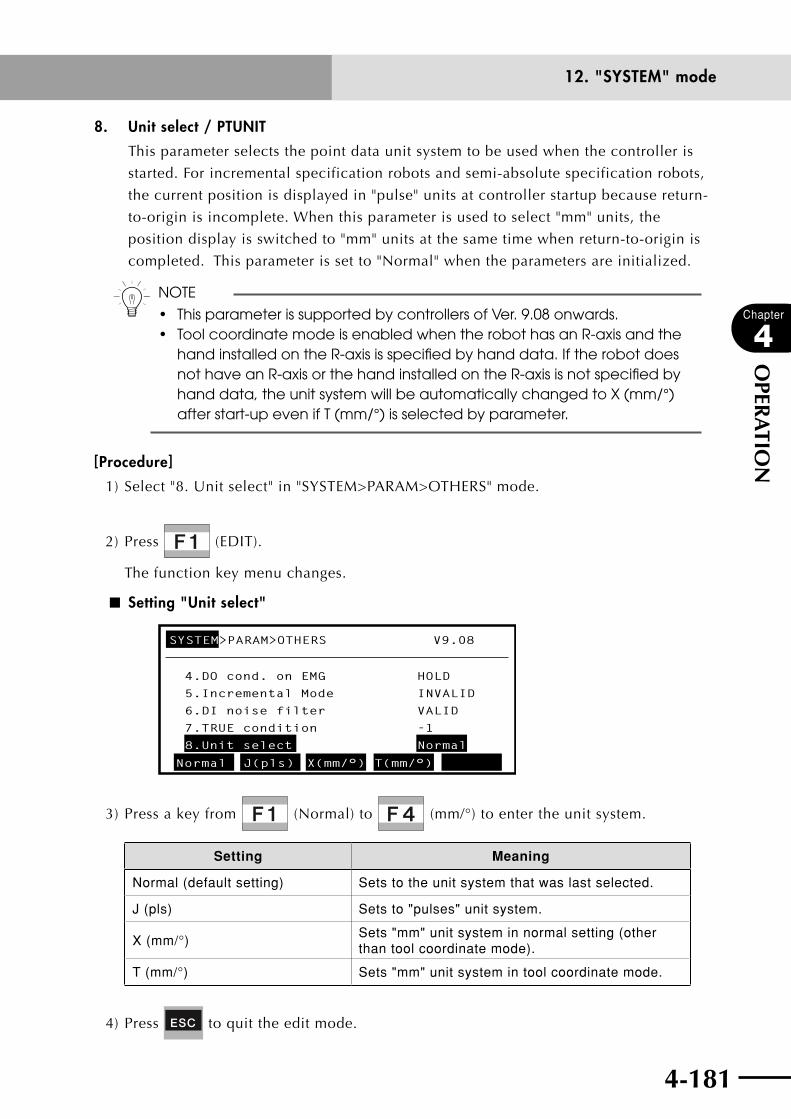
4-180 4-181
Chapter
4
OPER
ATIO
N
12. "SYSTEM" mode
8. Unit select / PTUNIT
This parameter selects the point data unit system to be used when the controller is
started. For incremental specification robots and semi-absolute specification robots,
the current position is displayed in "pulse" units at controller startup because return-
to-origin is incomplete. When this parameter is used to select "mm" units, the
position display is switched to "mm" units at the same time when return-to-origin is
completed. This parameter is set to "Normal" when the parameters are initialized.
n NOTE
• ThisparameterissupportedbycontrollersofVer.9.08onwards.• ToolcoordinatemodeisenabledwhentherobothasanR-axisandthe
hand installed on the R-axis is specified by hand data. If the robot does not have an R-axis or the hand installed on the R-axis is not specified by hand data, the unit system will be automatically changed to X (mm/°) after start-up even if T (mm/°) is selected by parameter.
[Procedure]
1) Select "8. Unit select" in "SYSTEM>PARAM>OTHERS" mode.
2) Press (EDIT).
The function key menu changes.
■ Setting "Unit select"
SYSTEM>PARAM>OTHERS V9.08
Normal J(pls) X(mm/°) T(mm/°)
4.DO cond. on EMG HOLD
5.Incremental Mode INVALID
6.DI noise filter VALID
7.TRUE condition -1
8.Unit select Normal
3) Press a key from (Normal) to (mm/°) to enter the unit system.
Setting Meaning
Normal (default setting) Sets to the unit system that was last selected.
J (pls) Sets to "pulses" unit system.
X (mm/°)Sets "mm" unit system in normal setting (other than tool coordinate mode).
T (mm/°) Sets "mm" unit system in tool coordinate mode.
4) Press to quit the edit mode.
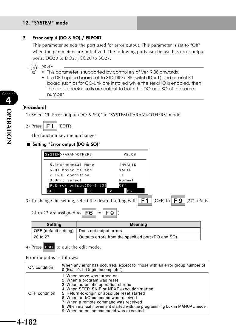
4-182
Chapter
4
OPER
ATIO
N
4-183
12. "SYSTEM" mode
9. Error output (DO & SO) / ERPORT
This parameter selects the port used for error output. This parameter is set to "Off"
when the parameters are initialized. The following ports can be used as error output
ports: DO20 to DO27, SO20 to SO27.
n NOTE• ThisparameterissupportedbycontrollersofVer.9.08onwards. • IfaDIOoptionboardsettoSTD.DIO(DIPswitchID=1)andaserialIO board such as for CC-Link are installed while the serial IO is enabled, then the area check results are output to both the DO and SO of the same number.
[Procedure]
1) Select "9. Error output (DO & SO)" in "SYSTEM>PARAM>OTHERS" mode.
2) Press (EDIT).
The function key menu changes.
■ Setting "Error output (DO & SO)"
SYSTEM>PARAM>OTHERS V9.08
OFF 20 21 22 23
5.Incremental Mode INVALID
6.DI noise filter VALID
7.TRUE condition -1
8.Unit select Normal
9.Error output(DO & SO) Off
3) To change the setting, select the desired setting with (OFF) to (27). (Ports
24 to 27 are assigned to to .)
Setting Meaning
OFF (default setting) Does not output errors.
20 to 27 Outputs errors from the specified port (DO and SO).
4) Press to quit the edit mode.
Error output is as follows:
ON condition When any error has occurred, except for those with an error group number of 0 (Ex.: "0.1: Origin incomplete")
OFF condition
1. When servo was turned on 2. When a program was reset 3. When automatic operation started 4. When STEP, SKIP or NEXT execution started 5. Return-to-origin or absolute reset started 6. When an I/O command was received 7. When a remote command was received 8. When manual movement started with the programming box in MANUAL mode 9. When an online command was executed
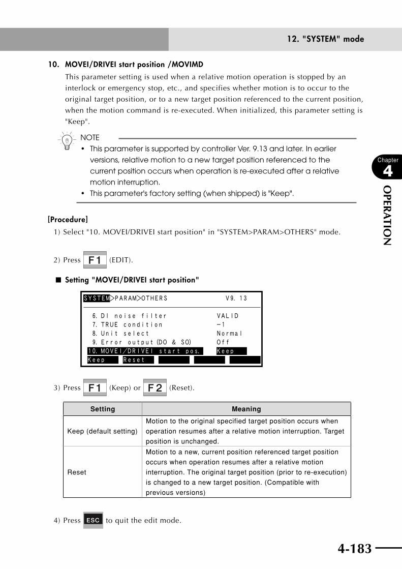
4-182 4-183
Chapter
4
OPER
ATIO
N
12. "SYSTEM" mode
10. MOVEI/DRIVEI start position /MOVIMD
This parameter setting is used when a relative motion operation is stopped by an
interlock or emergency stop, etc., and specifies whether motion is to occur to the
original target position, or to a new target position referenced to the current position,
when the motion command is re-executed. When initialized, this parameter setting is
"Keep".
n NOTE
• ThisparameterissupportedbycontrollerVer.9.13andlater.Inearlier
versions, relative motion to a new target position referenced to the
current position occurs when operation is re-executed after a relative
motion interruption.
• Thisparameter'sfactorysetting(whenshipped)is"Keep".
[Procedure]
1) Select "10. MOVEI/DRIVEI start position" in "SYSTEM>PARAM>OTHERS" mode.
2) Press (EDIT).
■ Setting "MOVEI/DRIVEI start position"
SYSTEM>PARAM>OTHERS V9.13
9.Error output(DO & SO) Off8.Unit select Normal7.TRUE condition -16.DI noise filter VALID
Keep Reset10.MOVEI/DRIVEI start pos. Keep
3) Press (Keep) or (Reset).
Setting Meaning
Keep (default setting)
Motion to the original specified target position occurs when
operation resumes after a relative motion interruption. Target
position is unchanged.
Reset
Motion to a new, current position referenced target position
occurs when operation resumes after a relative motion
interruption. The original target position (prior to re-execution)
is changed to a new target position. (Compatible with
previous versions)
4) Press to quit the edit mode.
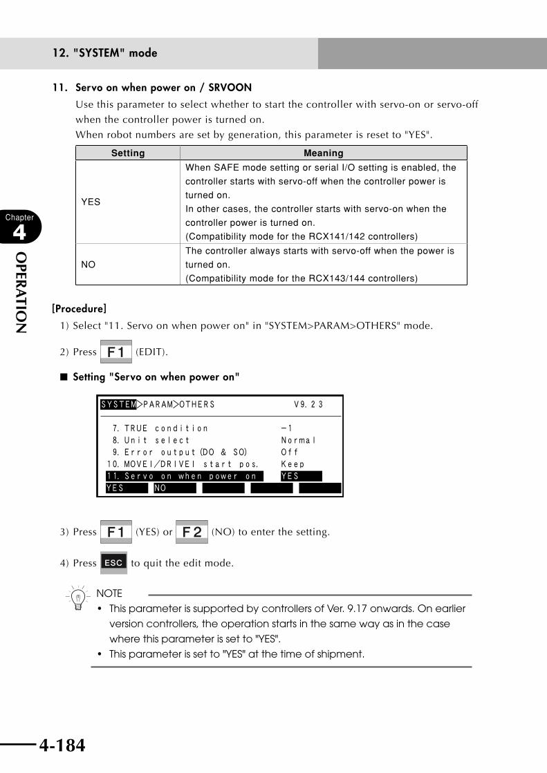
4-184
Chapter
4
OPER
ATIO
N
4-185
12. "SYSTEM" mode
11. Servo on when power on / SRVOON
Use this parameter to select whether to start the controller with servo-on or servo-off
when the controller power is turned on.
When robot numbers are set by generation, this parameter is reset to "YES".
Setting Meaning
YES
When SAFE mode setting or serial I/O setting is enabled, the
controller starts with servo-off when the controller power is
turned on.
In other cases, the controller starts with servo-on when the
controller power is turned on.
(Compatibility mode for the RCX141/142 controllers)
NO
The controller always starts with servo-off when the power is
turned on.
(Compatibility mode for the RCX143/144 controllers)
[Procedure]
1) Select "11. Servo on when power on" in "SYSTEM>PARAM>OTHERS" mode.
2) Press (EDIT).
■ Setting "Servo on when power on"
SYSTEM>PARAM>OTHERS V9.2 3
9.Error output(DO & SO) Off10.MOVEI/DRIVEI start pos. Keep11.Servo on when power on YES
8.Unit select Normal7.TRUE condition -1
YES NO
3) Press (YES) or (NO) to enter the setting.
4) Press to quit the edit mode.
n NOTE
• ThisparameterissupportedbycontrollersofVer.9.17onwards.Onearlier
version controllers, the operation starts in the same way as in the case
where this parameter is set to "YES".
• Thisparameterissetto"YES"atthetimeofshipment.

4-184 4-185
Chapter
4
OPER
ATIO
N
12. "SYSTEM" mode
12. Manual move mode /MOVMOD
When an axis movement key is held down, inching movement switches to continuous
movement. Use this parameter to shorten the time taken to switch to the continuous
movement.
This parameter can also be used for the online command @JOG and jog movement
command of remote commands to shorten the time taken to switch from the inching
movement to the continuous movement.
n NOTE
This parameter is enabled from controllers with software version 9.31 onwards.
Setting Meaning
NORMAL Standard operation
Manual movement
Switches to continuous movement when an axis movement key is held down for a certain time (approx. 0.2 sec.) after inching movement is complete.
@JOG (online command) Jog movement command (remote command)
Switches to continuous movement when a certain time (approx. 0.2 sec.) has elapsed after inching movement is complete.
MODE1
Continuous movement begins immediately after inching movement is complete.
Manual movement Switches to continuous movement immediately after inching movement is complete.
@JOG (online command) Jog movement command (remote command)
[Procedure]
1) Select "12. Manual move mode" in "SYSTEM>PARAM>OTHERS" mode.
2) Press (EDIT).
■ Setting "Manual move mode"
SYSTEM>PARAM>OTHERS V9.3 1
10.MOVEI/DRIVEI start pos. Keep11.Servo on when power on YES12.Manual move mode NORMAL
9.Error output(DO & SO) Off8.Unit select Normal
NORMAL MODE1
3) Press (NORMAL) or (MODE1) to set the manual move mode.
4) Press to quit the edit mode.

4-186
Chapter
4
OPER
ATIO
N
4-187
12. "SYSTEM" mode
13. DO cond. on PGM reset / RESCDO
Use this parameter to select whether to reset the DO/MO/LO/TO/SO port outputs
when a program is reset or a HALT statement is executed. When initialized, this
parameter is set to "RESET".
n NOTE
Thisparameterisenabledfromcontrollerswithsoftwareversion9.34onwards.
Setting Meaning
RESETStandard operation (Default setting)
The DO/MO/LO/TO/SO port outputs are reset when any
of the following operations are executed. However, the
outputs are not reset if a sequence program is being
executed without enabling the DO reset in the sequence
execution flag setting.
The outputs are reset:
n When compile ended successfully in "PROGRAM"
mode.
n When a program was compiled in "AUTO" mode and
the compile ended successfully.
n When (RESET) was executed in "AUTO" mode.
n In "AUTO" mode, when the dedicated input signal
DI15 or SI15 (Program reset input) was turned on
while the program was stopped. (See "1.7 Dedicated
I/O signals" in Chapter 5.)
n When either of the following was initialized in
"SYSTEM>INIT" mode.
1. Program memory
(SYSTEM>INIT>MEMORY>PROGRAM)
2. All memories
(SYSTEM>INIT>MEMORY>ALL)
n When the SWI command was executed by "DIRECT"
in "AUTO" mode.
(Reset (off) does not occur when the SWI command
was executed in the program.)
n When an online command @RESET, @INIT PGM,
@INIT MEM, @INIT ALL or @SWI was executed.
n When the HALT statement was executed in the
program.
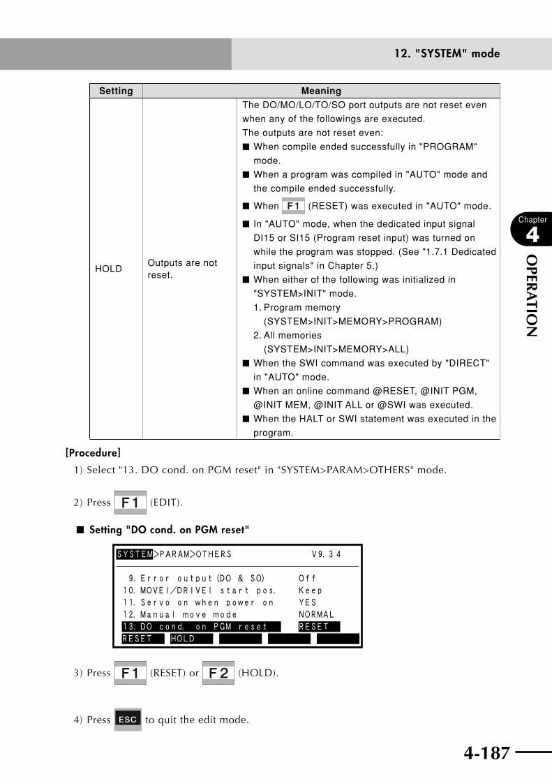
4-186 4-187
Chapter
4
OPER
ATIO
N
12. "SYSTEM" mode
Setting Meaning
HOLDOutputs are not reset.
The DO/MO/LO/TO/SO port outputs are not reset even
when any of the followings are executed.
The outputs are not reset even:
n When compile ended successfully in "PROGRAM"
mode.
n When a program was compiled in "AUTO" mode and
the compile ended successfully.
n When (RESET) was executed in "AUTO" mode.
n In "AUTO" mode, when the dedicated input signal
DI15 or SI15 (Program reset input) was turned on
while the program was stopped. (See "1.7.1 Dedicated
input signals" in Chapter 5.)
n When either of the following was initialized in
"SYSTEM>INIT" mode.
1. Program memory
(SYSTEM>INIT>MEMORY>PROGRAM)
2. All memories
(SYSTEM>INIT>MEMORY>ALL)
n When the SWI command was executed by "DIRECT"
in "AUTO" mode.
n When an online command @RESET, @INIT PGM,
@INIT MEM, @INIT ALL or @SWI was executed.
n When the HALT or SWI statement was executed in the
program.
[Procedure]
1) Select "13. DO cond. on PGM reset" in "SYSTEM>PARAM>OTHERS" mode.
2) Press (EDIT).
n Setting "DO cond. on PGM reset"
SYSTEM>PARAM>OTHERS V9.3 4
11.Servo on when power on YES10.MOVEI/DRIVEI start pos. Keep
12.Manual move mode NORMAL13.DO cond. on PGM reset RESET
9.Error output(DO & SO) Off
RESET HOLD
3) Press (RESET) or (HOLD).
4) Press to quit the edit mode.
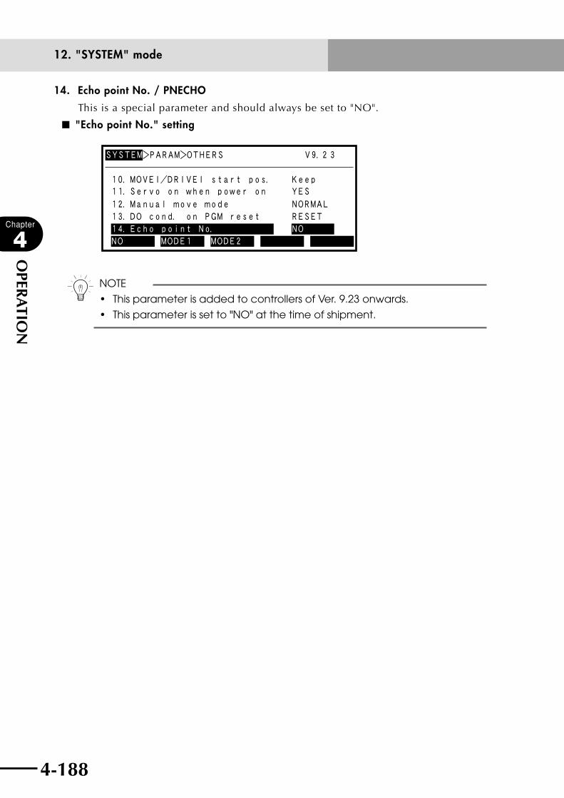
4-188
Chapter
4
OPER
ATIO
N
4-189
12. "SYSTEM" mode
14. Echo point No. / PNECHO
This is a special parameter and should always be set to "NO".
■ "Echo point No." setting
SYSTEM>PARAM>OTHERS V9.2 3
12.Manual move mode NORMAL
11.Servo on when power on YES10.MOVEI/DRIVEI start pos. Keep
13.DO cond. on PGM reset RESET14.Echo point No. NONO MODE1 MODE2
n NOTE
• ThisparameterisaddedtocontrollersofVer.9.23onwards.
• Thisparameterissetto"NO"atthetimeofshipment.
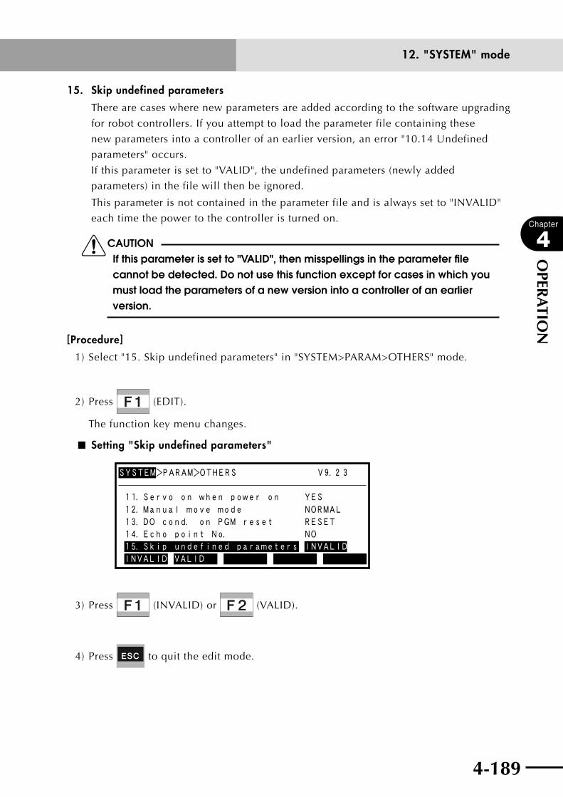
4-188 4-189
Chapter
4
OPER
ATIO
N
12. "SYSTEM" mode
15. Skip undefined parameters
There are cases where new parameters are added according to the software upgrading
for robot controllers. If you attempt to load the parameter file containing these
new parameters into a controller of an earlier version, an error "10.14 Undefined
parameters" occurs.
If this parameter is set to "VALID", the undefined parameters (newly added
parameters) in the file will then be ignored.
This parameter is not contained in the parameter file and is always set to "INVALID"
each time the power to the controller is turned on.
cCAUTIONIf this parameter is set to "VALID", then misspellings in the parameter file cannot be detected. Do not use this function except for cases in which you must load the parameters of a new version into a controller of an earlier version.
[Procedure]
1) Select "15. Skip undefined parameters" in "SYSTEM>PARAM>OTHERS" mode.
2) Press (EDIT).
The function key menu changes.
■ Setting "Skip undefined parameters"
SYSTEM>PARAM>OTHERS V9.2 3
15.Skip undefined parameters INVALID
12.Manual move mode NORMAL
11.Servo on when power on YES
13.DO cond. on PGM reset RESET14.Echo point No. NO
INVALID VALID
3) Press (INVALID) or (VALID).
4) Press to quit the edit mode.

4-190
Chapter
4
OPER
ATIO
N
4-191
12. "SYSTEM" mode
12.1.4 Parameters for option boardsThis section explains how to set parameters for option boards from the RPB.
Option boards are roughly divided into three types: option DIO boards, serial I/O boards
and network board.
For option DIO boards, there are 2 parameters to be set, including the parameter to enable
or disable the DC 24V power input monitor. For serial I/O boards (CC-Link/DeviceNet/
PROFIBUS), there are 3 parameters including the parameter to enable or disable the
boards. When using a network board (Ethernet), there are 4 parameters including the
parameter to enable or disable the board.
n NOTE
• FordetailedinformationonserialI/OunitssuchasCC-Link,Ethernet,and
YC-Link, refer to their respective manuals.
• OncontrollerswithaDeviceNetboardinstalledandfromVer.9.08
onwards, there are 4 parameters to be set. Earlier version controllers
require 3 parameters to be set.
• NoparametersettingisrequiredfortheYC-Link.
[Procedure]
1) Press (OP. BRD) in "SYSTEM>PARAM" mode to enter the option board
parameter setting mode.
The option boards installed in the controller are displayed in order on the RPB screen.
■ Option board parameter screen
SYSTEM>PARAM>OP.BRD V9.00
1.D_Net(M4/500k)
VALID
2.DIO_P(n)
VALID
3. ---
4. ---
SELECT
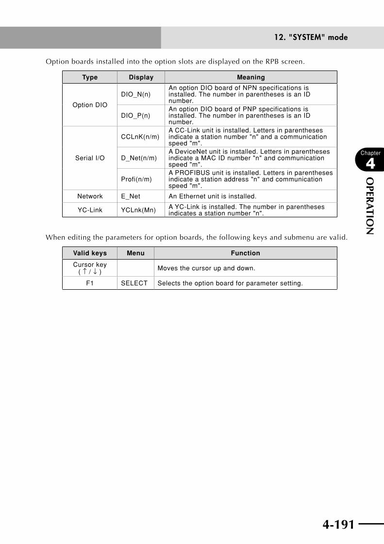
4-190 4-191
Chapter
4
OPER
ATIO
N
12. "SYSTEM" mode
Option boards installed into the option slots are displayed on the RPB screen.
Type Display Meaning
Option DIO
DIO_N(n)An option DIO board of NPN specifications is installed. The number in parentheses is an ID number.
DIO_P(n)An option DIO board of PNP specifications is installed. The number in parentheses is an ID number.
Serial I/O
CCLnK(n/m)A CC-Link unit is installed. Letters in parentheses indicate a station number "n" and a communication speed "m".
D_Net(n/m)A DeviceNet unit is installed. Letters in parentheses indicate a MAC ID number "n" and communication speed "m".
Profi(n/m)A PROFIBUS unit is installed. Letters in parentheses indicate a station address "n" and communication speed "m".
Network E_Net An Ethernet unit is installed.
YC-Link YCLnk(Mn) A YC-Link is installed. The number in parentheses indicates a station number "n".
When editing the parameters for option boards, the following keys and submenu are valid.
Valid keys Menu Function
Cursor key ( ↑ / ↓ ) Moves the cursor up and down.
F1 SELECT Selects the option board for parameter setting.
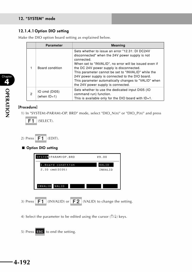
4-192
Chapter
4
OPER
ATIO
N
4-193
12. "SYSTEM" mode
12.1.4.1 Option DIO setting
Make the DIO option board setting as explained below.
Parameter Meaning
1 Board condition
Sets whether to issue an error "12.31: DI DC24V disconnected" when the 24V power supply is not connected. When set to "INVALID", no error will be issued even if the DC 24V power supply is disconnected. This parameter cannot be set to "INVALID" while the 24V power supply is connected to the DIO board. This parameter automatically changes to "VALID" when the 24V power supply is connected.
2IO cmd (DI05)
(when ID=1)
Sets whether to use the dedicated input DI05 (IO command run) function. This is available only for the DIO board with ID=1.
[Procedure]
1) In "SYSTEM>PARAM>OP. BRD" mode, select "DIO_N(n)" or "DIO_P(n)" and press
(SELECT).
2) Press (EDIT).
■ Option DIO setting
SYSTEM>PARAM>OP.BRD V9.00
1.Board condition
2.IO cmd(DI05)
VALID
INVALID
INVALID
VALID
3) Press (INVALID) or (VALID) to change the setting.
4) Select the parameter to be edited using the cursor (↑/↓) keys.
5) Press to end the setting.
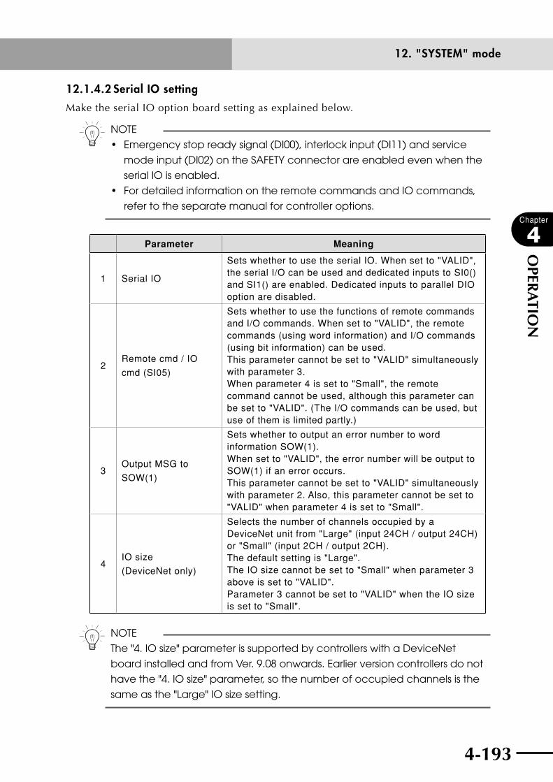
4-192 4-193
Chapter
4
OPER
ATIO
N
12. "SYSTEM" mode
12.1.4.2 Serial IO setting
Make the serial IO option board setting as explained below.
n NOTE
• Emergencystopreadysignal(DI00),interlockinput(DI11)andservice
mode input (DI02) on the SAFETY connector are enabled even when the
serial IO is enabled.
• FordetailedinformationontheremotecommandsandIOcommands,
refer to the separate manual for controller options.
Parameter Meaning
1 Serial IO
Sets whether to use the serial IO. When set to "VALID", the serial I/O can be used and dedicated inputs to SI0() and SI1() are enabled. Dedicated inputs to parallel DIO option are disabled.
2Remote cmd / IO
cmd (SI05)
Sets whether to use the functions of remote commands and I/O commands. When set to "VALID", the remote commands (using word information) and I/O commands (using bit information) can be used. This parameter cannot be set to "VALID" simultaneously with parameter 3. When parameter 4 is set to "Small", the remote command cannot be used, although this parameter can be set to "VALID". (The I/O commands can be used, but use of them is limited partly.)
3Output MSG to
SOW(1)
Sets whether to output an error number to word information SOW(1). When set to "VALID", the error number will be output to SOW(1) if an error occurs. This parameter cannot be set to "VALID" simultaneously with parameter 2. Also, this parameter cannot be set to "VALID" when parameter 4 is set to "Small".
4IO size
(DeviceNet only)
Selects the number of channels occupied by a DeviceNet unit from "Large" (input 24CH / output 24CH) or "Small" (input 2CH / output 2CH). The default setting is "Large". The IO size cannot be set to "Small" when parameter 3 above is set to "VALID". Parameter 3 cannot be set to "VALID" when the IO size is set to "Small".
n NOTE
The "4. IO size" parameter is supported by controllers with a DeviceNet
board installed and from Ver. 9.08 onwards. Earlier version controllers do not
have the "4. IO size" parameter, so the number of occupied channels is the
same as the "Large" IO size setting.
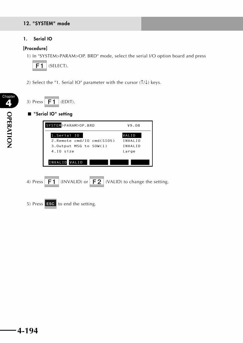
4-194
Chapter
4
OPER
ATIO
N
4-195
12. "SYSTEM" mode
1. Serial IO
[Procedure]
1) In "SYSTEM>PARAM>OP. BRD" mode, select the serial I/O option board and press
(SELECT).
2) Select the "1. Serial IO" parameter with the cursor (↑/↓) keys.
3) Press (EDIT).
■ "Serial IO" setting
SYSTEM>PARAM>OP.BRD V9.08
1.Serial IO VALID
2.Remote cmd/IO cmd(SI05) INVALID
3.Output MSG to SOW(1) INVALID
4.IO size Large
INVALID VALID
4) Press (INVALID) or (VALID) to change the setting.
5) Press to end the setting.

4-194 4-195
Chapter
4
OPER
ATIO
N
12. "SYSTEM" mode
2. Remote cmd/IO cmd (SI05)
[Procedure]
1) In "SYSTEM>PARAM>OP. BRD" mode, select the serial I/O option board and press
(SELECT).
2) Select the "2. Remote cmd / IO cmd (SI05)" parameter with the cursor (↑/↓) keys.
3) Press (EDIT).
■ "Remote cmd / IO cmd (SI05)" setting
SYSTEM>PARAM>OP.BRD V9.08
1.Serial IO VALID
2.Remote cmd/IO cmd(SI05) INVALID
3.Output MSG to SOW(1) INVALID
4.IO size Large
INVALID VALID
4) Press (INVALID) or (VALID) to change the setting.
5) Press to end the setting.

4-196
Chapter
4
OPER
ATIO
N
4-197
12. "SYSTEM" mode
3. Output MSG to SOW(1)
[Procedure]
1) In "SYSTEM>PARAM>OP. BRD" mode, select the serial I/O option board and press
(SELECT).
2) Select the "3. Output MSG to SOW(1)" parameter with the cursor (↑/↓) keys.
3) Press (EDIT).
■ "Output MSG to SOW(1)" setting
SYSTEM>PARAM>OP.BRD V9.08
1.Serial IO VALID
2.Remote cmd/IO cmd(SI05) INVALID
3.Output MSG to SOW(1) INVALID
4.IO size Large
INVALID VALID
4) Press (INVALID) or (VALID) to change the setting.
5) Press to end the setting.

4-196 4-197
Chapter
4
OPER
ATIO
N
12. "SYSTEM" mode
4. IO size (DeviceNet only)
n NOTE
This parameter is supported by controllers with a DeviceNet board installed
and from Ver. 9.08 onwards. Earlier version controllers do not have this "4. IO
size" parameter, so the number of occupied channels is the same as the
"Large" IO size setting.
[Procedure]
1) In "SYSTEM>PARAM>OP. BRD" mode, select the serial I/O option board and press
(SELECT).
2) Select the "4. IO size" parameter with the cursor (↑/↓) keys.
3) Press (EDIT).
■ "IO size" setting
SYSTEM>PARAM>OP.BRD V9.08
1.Serial IO VALID2.Remote cmd/IO cmd(SI05) INVALID3.Output MSG to SOW(1) INVALID4.IO size Large
Large Small
4) Press (Large) to use 24CH each of input/output or (Small) to use 2CH
each of input/output.
5) Press to end the setting.
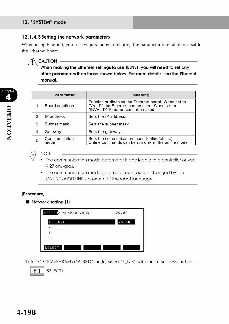
4-198
Chapter
4
OPER
ATIO
N
4-199
12. "SYSTEM" mode
12.1.4.3 Setting the network parameters
When using Ethernet, you set five parameters including the parameter to enable or disable
the Ethernet board.
cCAUTIONWhen making the Ethernet settings to use TELNET, you will need to set any other parameters than those shown below. For more details, see the Ethernet manual.
Parameter Meaning
1 Board conditionEnables or disables the Ethernet board. When set to "VALID" the Ethernet can be used. When set to "INVALID" Ethernet cannot be used.
2 IP address Sets the IP address.
3 Subnet mask Sets the subnet mask.
4 Gateway Sets the gateway.
5 Communication mode
Sets the communication mode (online/offline). Online commands can be run only in the online mode.
n NOTE
• ThecommunicationmodeparameterisapplicabletoacontrollerofVer.
9.27 onwards.
• Thecommunicationmodeparametercanalsobechangedbythe
ONLINE or OFFLINE statement of the robot language.
[Procedure]
■ Network setting (1)
SYSTEM>PARAM>OP.BRD V9.00
1.E_Net
VALID
2.
3.
4.
SELECT
1) In "SYSTEM>PARAM>OP. BRD" mode, select "E_Net" with the cursor keys and press
(SELECT).
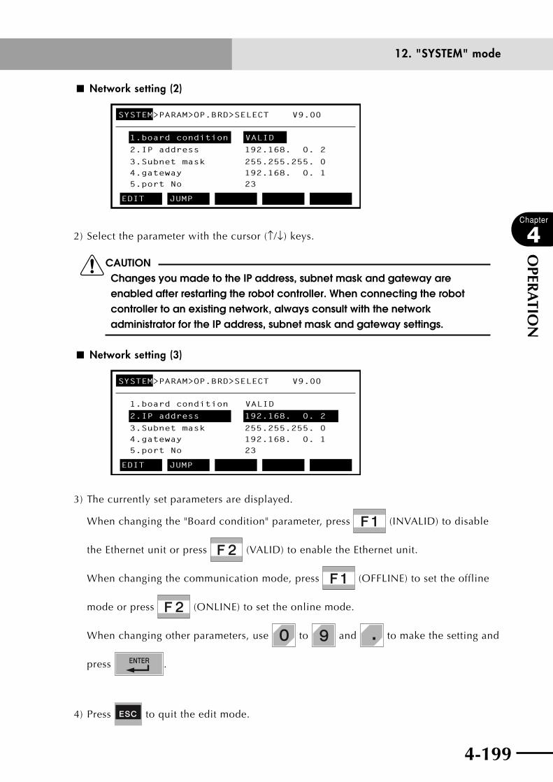
4-198 4-199
Chapter
4
OPER
ATIO
N
12. "SYSTEM" mode
■ Network setting (2)
SYSTEM>PARAM>OP.BRD>SELECT V9.00
1.board condition VALID
2.IP address
3.Subnet mask4.gateway5.port No
192.168. 0. 2
255.255.255. 0192.168. 0. 123
EDIT JUMP
2) Select the parameter with the cursor (↑/↓) keys.
cCAUTIONChanges you made to the IP address, subnet mask and gateway are enabled after restarting the robot controller. When connecting the robot controller to an existing network, always consult with the network administrator for the IP address, subnet mask and gateway settings.
■ Network setting (3)
SYSTEM>PARAM>OP.BRD>SELECT V9.00
1.board condition VALID
2.IP address
3.Subnet mask4.gateway5.port No
192.168. 0. 2
255.255.255. 0192.168. 0. 123
EDIT JUMP
3) The currently set parameters are displayed.
When changing the "Board condition" parameter, press (INVALID) to disable
the Ethernet unit or press (VALID) to enable the Ethernet unit.
When changing the communication mode, press (OFFLINE) to set the offline
mode or press (ONLINE) to set the online mode.
When changing other parameters, use to and to make the setting and
press .
4) Press to quit the edit mode.
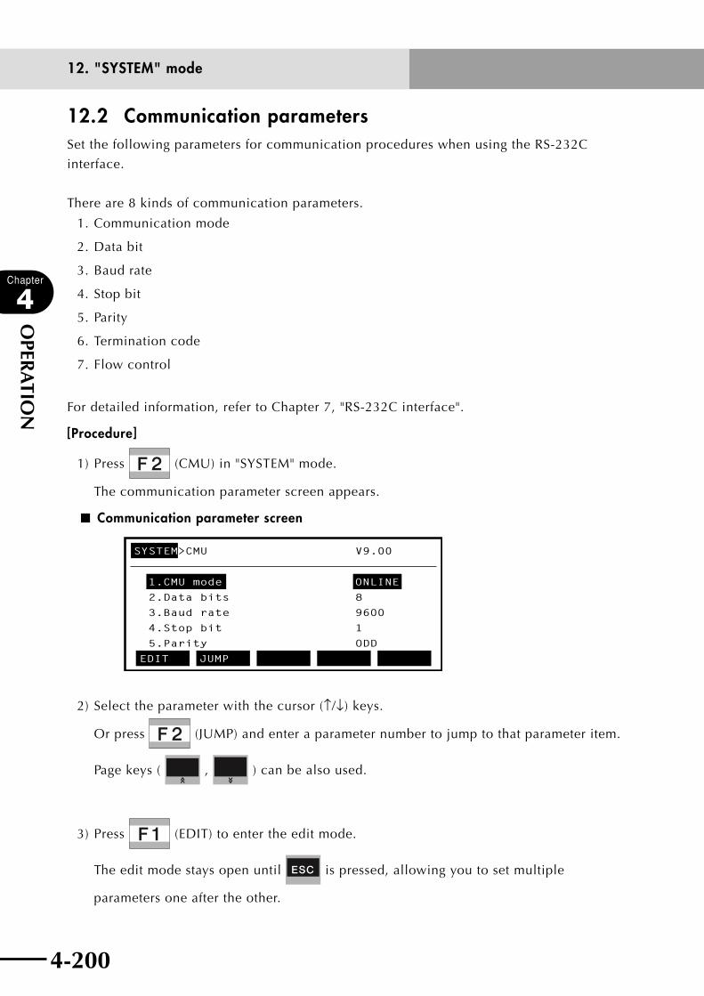
4-200
Chapter
4
OPER
ATIO
N
4-201
12. "SYSTEM" mode
12.2 Communication parametersSet the following parameters for communication procedures when using the RS-232C
interface.
There are 8 kinds of communication parameters.
1. Communication mode
2. Data bit
3. Baud rate
4. Stop bit
5. Parity
6. Termination code
7. Flow control
For detailed information, refer to Chapter 7, "RS-232C interface".
[Procedure]
1) Press (CMU) in "SYSTEM" mode.
The communication parameter screen appears.
■ Communication parameter screen
SYSTEM>CMU V9.00
1.CMU mode ONLINE
2.Data bits 8
3.Baud rate 9600
4.Stop bit 1
5.Parity ODD
EDIT JUMP
2) Select the parameter with the cursor (↑/↓) keys.
Or press (JUMP) and enter a parameter number to jump to that parameter item.
Page keys ( , ) can be also used.
3) Press (EDIT) to enter the edit mode.
The edit mode stays open until is pressed, allowing you to set multiple
parameters one after the other.

4-200 4-201
Chapter
4
OPER
ATIO
N
12. "SYSTEM" mode
4) Set the parameter with the function keys.
The selectable values or items appear as function key menus on the guideline.
5) Press to quit the setting. To continue selecting other items, use the cursor (↑/↓)
keys.
Valid keys and submenu descriptions in "SYSTEM>CMU" mode are shown below.
Valid keys Menu Function
Cursor key ( ↑ / ↓ ) Moves the cursor up and down.
Page key (
〈〈 / 〈〈 ) Switches to other screens.
F1 EDIT Edits the parameter.
F2 JUMP Moves the cursor to the designated parameter.

4-202
Chapter
4
OPER
ATIO
N
4-203
12. "SYSTEM" mode
1. CMU (communication) mode
This parameter sets the communication mode on the computer.
n NOTE
• Onlinecommandscanbeexecutedonlyin"ONLINE"mode.
• TheCMU(communication)modecanbechangedwitheitherONLINEor
OFFLINE statements in robot language.
[Procedure]
1) Select "1. CMU mode" in "SYSTEM>CMU" mode.
2) Press (EDIT).
The function key menu changes.
■ Setting the "CMU mode"
SYSTEM>CMU V9.00
1.CMU mode ONLINE
2.Data bits 8
3.Baud rate 9600
4.Stop bit 1
5.Parity ODD
ONLINEOFFLINE
3) Select the communication mode with (OFFLINE) or (ONLINE).
4) Press to quit the setting. To continue selecting other items, use the cursor (↑/↓)
keys.

4-202 4-203
Chapter
4
OPER
ATIO
N
12. "SYSTEM" mode
2. Data bits
This parameter sets the data bit length.
n NOTE
Katakana letters (Japanese phonetic) cannot be sent if data bit length was
set to 7 bits.
[Procedure]
1) Select "2. Data bits" in "SYSTEM>CMU" mode.
2) Press (EDIT).
The function key menu changes.
■ Setting the "Data bits"
SYSTEM>CMU V9.00
1.CMU mode ONLINE
2.Data bits 8
3.Baud rate 9600
4.Stop bit 1
5.Parity ODD
7 8
3) Select the data bits with (7) or (8).
4) Press to quit the setting. To continue selecting other items, use the cursor (↑/↓)
keys.

4-204
Chapter
4
OPER
ATIO
N
4-205
12. "SYSTEM" mode
3. Baud rate
This parameter sets the communication speed.
n NOTE
Communication errors are more prone to occur at high communication
speeds. If communication errors frequently occur, set a lower
communication speed.
[Procedure]
1) Select "3. Baud rate" in "SYSTEM>CMU" mode.
2) Press (EDIT).
The function key menu changes.
■ Setting the "Baud rate"
SYSTEM>CMU V9.00
1.CMU mode ONLINE
2.Data bits 8
3.Baud rate 9600
4.Stop bit 1
5.Parity ODD
4800 9600 19200 38400 57600
3) Select the baud rate with (4800) through (57600).
4) Press to quit the setting. To continue selecting other items, use the cursor (↑/↓)
keys.
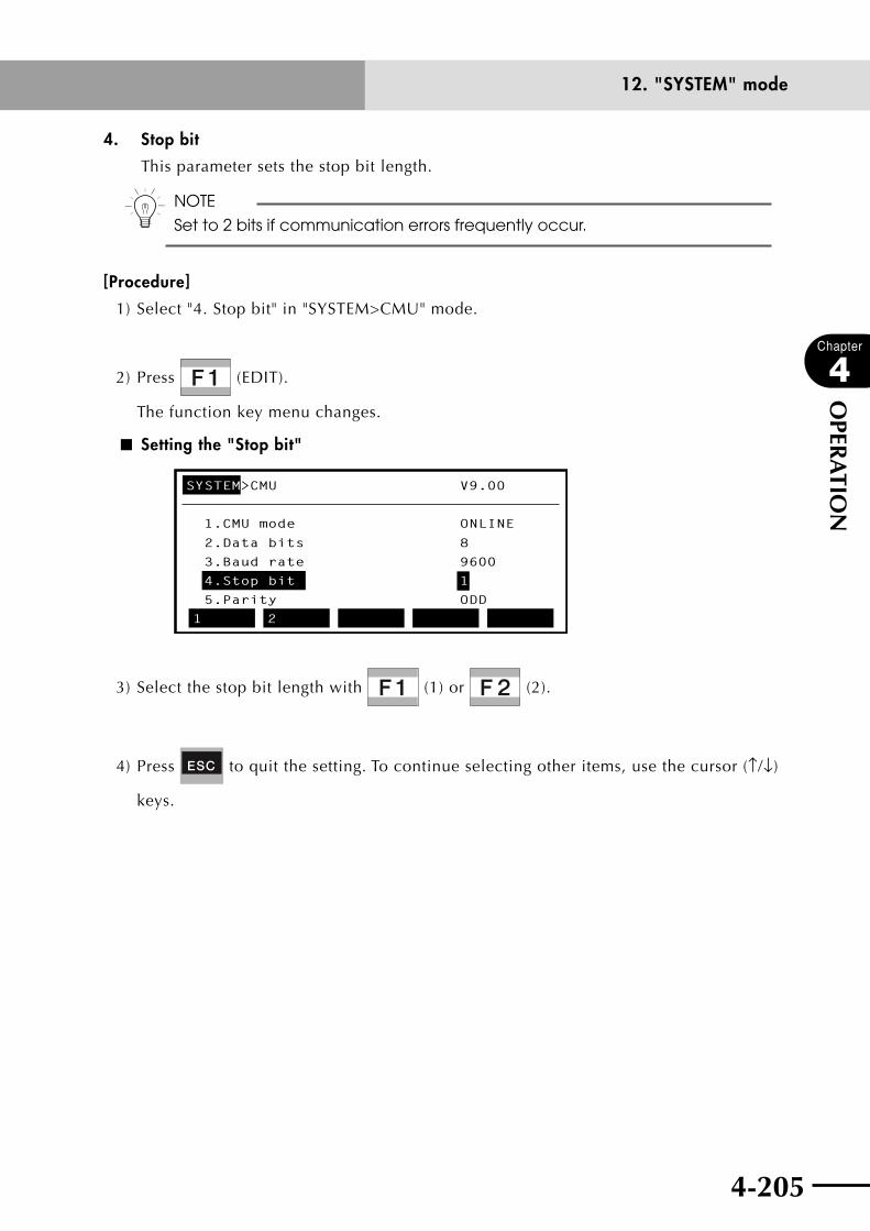
4-204 4-205
Chapter
4
OPER
ATIO
N
12. "SYSTEM" mode
4. Stop bit
This parameter sets the stop bit length.
n NOTE
Set to 2 bits if communication errors frequently occur.
[Procedure]
1) Select "4. Stop bit" in "SYSTEM>CMU" mode.
2) Press (EDIT).
The function key menu changes.
■ Setting the "Stop bit"
SYSTEM>CMU V9.00
1.CMU mode ONLINE
2.Data bits 8
3.Baud rate 9600
4.Stop bit 1
5.Parity ODD
1 2
3) Select the stop bit length with (1) or (2).
4) Press to quit the setting. To continue selecting other items, use the cursor (↑/↓)
keys.

4-206
Chapter
4
OPER
ATIO
N
4-207
12. "SYSTEM" mode
5. Parity
This parameter sets the parity check.
n NOTE
Use the parity check as often as possible.
[Procedure]
1) Select "5. Parity" in "SYSTEM>CMU" mode.
2) Press (EDIT).
The function key menu changes.
■ Setting the "Parity"
SYSTEM>CMU V9.00
1.CMU mode ONLINE
2.Data bits 8
3.Baud rate 9600
4.Stop bit 1
5.Parity ODD
NON ODD EVEN
3) Select the parity check with (NON), (ODD) or (EVEN).
4) Press to quit the setting. To continue selecting other items, use the cursor (↑/↓)
keys.
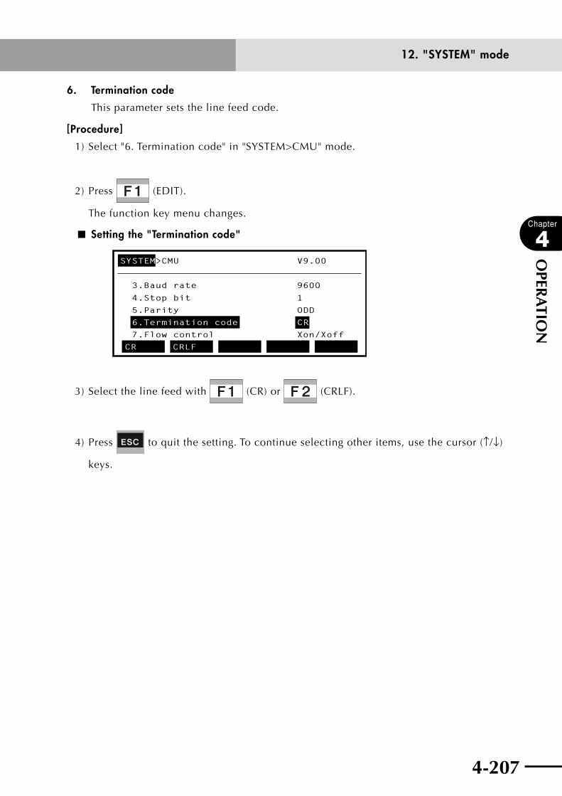
4-206 4-207
Chapter
4
OPER
ATIO
N
12. "SYSTEM" mode
6. Termination code
This parameter sets the line feed code.
[Procedure]
1) Select "6. Termination code" in "SYSTEM>CMU" mode.
2) Press (EDIT).
The function key menu changes.
■ Setting the "Termination code"
SYSTEM>CMU V9.00
3.Baud rate 9600
4.Stop bit 1
5.Parity ODD
6.Termination code CR
7.Flow control Xon/Xoff
CR CRLF
3) Select the line feed with (CR) or (CRLF).
4) Press to quit the setting. To continue selecting other items, use the cursor (↑/↓)
keys.

4-208
Chapter
4
OPER
ATIO
N
12. "SYSTEM" mode
7. Flow control
This parameter sets communication flow control.
n NOTE
Communication data omissions may occur if flow control is set to "NO".
[Procedure]
1) Select "7. Flow control" in "SYSTEM>CMU" mode.
2) Press (EDIT).
■ Flow control setting
SYSTEM>CMU V9.00
3.Baud rate 9600
4.Stop bit 1
5.Parity ODD
6.Termination code CR7.Flow control XonXoff
XonXoff RTS/CTS NO
3) Set flow control with (XonXoff) to (NO).
4) Press to end the setting.

4-209
Chapter
4
OPER
ATIO
N
12. "SYSTEM" mode
12.3 OPTION parametersThe OPTION parameters are used to set expanded controller functions. These parameters
consist of 4 types: parameters for area check output, parameters relating to SAFE mode,
parameters relating to the serial I/O, and parameters relating to double-carrier type robots.
[Procedure]
1) In "SYSTEM" mode, press (OPTION) to enter "SYSTEM>OPTION" mode.
2) In "SYSTEM>OPTION" mode, press a key from (POS.OUT) to (W.CARRY)
to show the parameter items.
■ OPTION parameter setting
SYSTEM>OPTION V9.00
POS.OUT SERVICE SIO W.CARRY
Parameters can be edited by entering data with the number keys or by selecting the
function keys. Refer to each parameter item for detailed information.
3) Press to quit the parameter edit mode.

4-210
Chapter
4
OPER
ATIO
N
4-211
12. "SYSTEM" mode
12.3.1 Setting the area check outputThis function checks whether the current robot position is within an area specified by the
area check output parameter’s point data, and outputs the result to the specified port.
A maximum of 4 areas can be checked with controllers prior to Ver. 9.22, while a
maximum of 8 areas can be checked with controllers of Ver. 9.22 onwards.
The area check output includes the following 5 parameters.
1. Area check on/off
Selects the robot for the area check.
2. Area check output port No.
Selects the port to output the area check results to.
The following port numbers can be used.
•ControllerspriortoVer.9.22
DO/SO Port No.
DO 20 to 27
SO 20 to 27
•ControllersofVer.9.22onwards
DO/SO Port No.
DO20 to 27, 30 to 37, 40 to 47, 50 to 57, 60 to 67, 70 to 77, 100 to 107 110 to 117*, 120 to 127*, 130 to 137*, 140 to 147*, 150 to 157*
SO20 to 27, 30 to 37, 40 to 47, 50 to 57, 60 to 67, 70 to 77, 100 to 107 110 to 117, 120 to 127, 130 to 137, 140 to 147, 150 to 157
* DO110 to DO157 do not exist as hardware, so these are not output to external devices but can be used as internal outputs.
3. Comparison point No. 1
4. Comparison point No. 2
Sets the points for determining the area. (Usable point No. : P0 to P4000)
The area is applied to all set axes.
5. Condition for area check output
Selects the condition that allows the area check output to turn on, from either when
the robot is within a specified area or when outside it.

4-210 4-211
Chapter
4
OPER
ATIO
N
12. "SYSTEM" mode
n NOTE
• Iftheportusedforareacheckoutputisthesameastheoutputportused
by the program, then the output data might be changed. So do not use
the same output port.
• Ifthesameportisdesignatedforadifferentareacheckoutput,ORwill
be output.
• OncontrollersofVer.9.08onwards,theareacheckcannotbeperformed
and an error is displayed unless comparison points exist or the units of
comparison points are the same. If this situation occurs during automatic
operation, the automatic operation stops and an error is displayed. The
area check output where the error occurred then turns off. Automatic
operation cannot be performed until the error is cleared.
On earlier version controllers, no error will occur even if comparison points
do not exist or the units of comparison points are not the same. Note,
however, that the area check output does not function correctly in this
case.
• Areacheckoutputwillnotfunctionifreturn-to-originisincomplete.
• Theareacheckisperformedonallsetaxes.
• Alwaysprovideamarginwhensettingthecomparisonpointdata.
• "5.Conditionforareacheckoutput"issupportedbycontrollersofVer.9.08
onwards. On earlier version controllers, the area check output turns on
when the robot is within a specified area, and turns off when outside it.
• Ifaportnumberwhichdoesnotexistisspecifiedastheareacheck
output port, no output will occur.

4-212
Chapter
4
OPER
ATIO
N
4-213
12. "SYSTEM" mode
When the comparison points are set as shown below, and the robot axis tip is moved
between the marks, the output is off at and the output is on at . (When
"5. Criterion selection for area check output" is set so that the area check output turns on
when the robot enters a specified area.)
■ When points are designated in Cartesian coordinates ("mm" unit system)
+X
+Y
Comparison point 2
Comparison point 1
[Procedure]
1) Press (POS.OUT) in "SYSTEM>OPTION" mode to enter the area check output
mode.
■ Selecting the area check output number (controllers prior to Ver. 9.22)
SYSTEM>OPTION>POS.OUT V9.08
1.Output of area1 NO
2.Output of area2 NO
3.Output of area3 NO
4.Output of area4 NO
SELECT
■ Selecting the area check output number (controllers of Ver. 9.22 onwards)
SYSTEM>OPTION>POS.OUT V9.22
1.Output of area1 NO 2.Output of area2 NO 3.Output of area3 NO 4.Output of area4 NO 5.Output of area5 NO SELECT
2) Select an area check output number with the cursor (↑/↓) keys and press
(SELECT).
A maximum of 4 areas can be checked with controllers prior to Ver. 9.22, while a
maximum of 8 areas can be checked with controllers of Ver. 9.22 onwards.
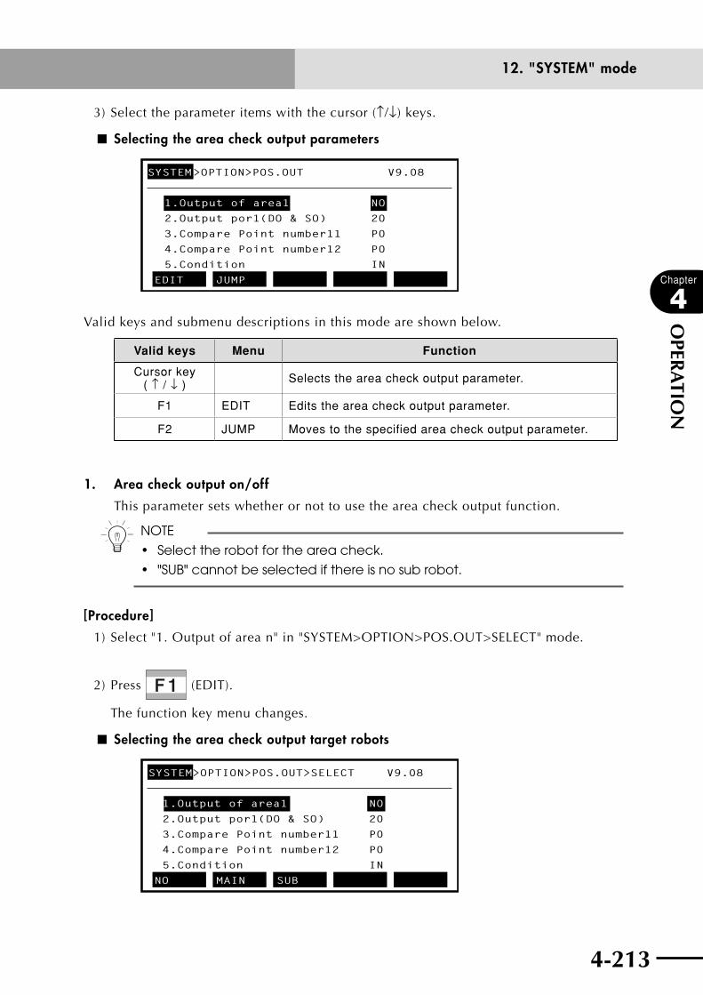
4-212 4-213
Chapter
4
OPER
ATIO
N
12. "SYSTEM" mode
3) Select the parameter items with the cursor (↑/↓) keys.
■ Selecting the area check output parameters
SYSTEM>OPTION>POS.OUT V9.08
1.Output of area1 NO
2.Output por1(DO & SO) 20
3.Compare Point number11 P0
4.Compare Point number12 P0
5.Condition IN
EDIT JUMP
Valid keys and submenu descriptions in this mode are shown below.
Valid keys Menu Function
Cursor key ( ↑ / ↓ ) Selects the area check output parameter.
F1 EDIT Edits the area check output parameter.
F2 JUMP Moves to the specified area check output parameter.
1. Area check output on/off
This parameter sets whether or not to use the area check output function.
n NOTE
• Selecttherobotfortheareacheck.
• "SUB"cannotbeselectedifthereisnosubrobot.
[Procedure]
1) Select "1. Output of area n" in "SYSTEM>OPTION>POS.OUT>SELECT" mode.
2) Press (EDIT).
The function key menu changes.
■ Selecting the area check output target robots
SYSTEM>OPTION>POS.OUT>SELECT V9.08
1.Output of area1 NO
2.Output por1(DO & SO) 20
3.Compare Point number11 P0
4.Compare Point number12 P0
5.Condition IN
NO MAIN SUB

4-214
Chapter
4
OPER
ATIO
N
4-215
12. "SYSTEM" mode
3) Select the robot for the area check with (NO), (MAIN) or (SUB).
Robot Details
NO The area check output is not executed.
MAIN The area check output is executed for the main robot.
SUB The area check output is executed for the sub robot.
4) Press to quit the setting. To continue selecting other items, use the cursor (↑/↓)
keys.
2. Area check output port No.
This parameter specifies the port to output the area check results to. The following
ports can be used as the area check output port.
•ControllerspriortoVer.9.22
DO/SO Port No.
DO 20 to 27
SO 20 to 27
•ControllersofVer.9.22onwards
DO/SO Port No.
DO20 to 27, 30 to 37, 40 to 47, 50 to 57, 60 to 67, 70 to 77, 100 to 107 110 to 117*, 120 to 127*, 130 to 137*, 140 to 147*, 150 to 157*
SO20 to 27, 30 to 37, 40 to 47, 50 to 57, 60 to 67, 70 to 77, 100 to 107 110 to 117, 120 to 127, 130 to 137, 140 to 147, 150 to 157
* DO110 to DO157 do not exist as hardware, so these are not output to external devices but can be used as internal outputs.
n NOTE
• Iftheportusedforareacheckoutputisthesameastheoutputportused
by the program, then the output data might be changed. So do not use
the same output port.
• IftheserialIOisenabledwhileaDIOoptionboardandaserialIOboard
such as for CC-Link are installed in the option board slots, then the area
check results will be output to both the DO and SO of the same number.
[Procedure]
[Controllers prior to Ver. 9.22]
1) Select "2. Port number of output n" in "SYSTEM>OPTION>POS.OUT>SELECT" mode.

4-214 4-215
Chapter
4
OPER
ATIO
N
12. "SYSTEM" mode
2) Press (EDIT).
The function key menu changes.
■ Selecting the area check output port (controllers prior to Ver. 9.22)
SYSTEM>OPTION>POS.OUT>SELECT V9.08
1.Output of area1 MAIN
2.Output por1(DO & SO) 20
3.Compare Point number11 P0
4.Compare Point number12 P0
5.Condition IN
20 21 22 23 24
3) Select the output port with (DO(20)) through (DO(27)).
4) Press to quit the setting. To continue selecting other items, use the cursor (↑/↓)
keys.
[Controllers of Ver. 9.22 onwards]
1) Select "2. Port number of output n" in "SYSTEM>OPTION>POS.OUT>SELECT" mode.
2) Press (EDIT).
The function key menu changes.
■ Selecting the area check output port (controllers of Ver. 9.22 onwards)
SYSTEM>OPTION>POS.OUT>SELECT V9.22
1.Output of area1 MAIN 2.Output por1(DO & SO) 20 3.Compare Point number11 P0 4.Compare Point number12 P1 5.Condition IN [20-157]Enter output port>0
3) Enter the output port number with to and press to determine it.
4) Press to quit the setting. To continue selecting other items, use the cursor (↑/↓)
keys.
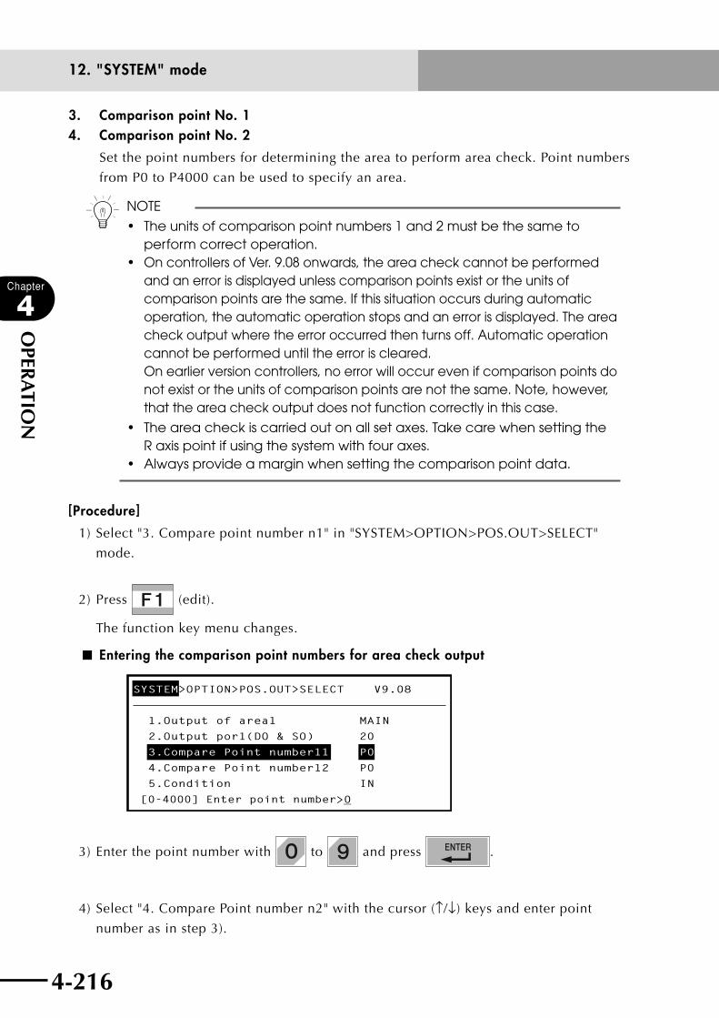
4-216
Chapter
4
OPER
ATIO
N
4-217
12. "SYSTEM" mode
3. Comparison point No. 1 4. Comparison point No. 2
Set the point numbers for determining the area to perform area check. Point numbers
from P0 to P4000 can be used to specify an area.
n NOTE
• Theunitsofcomparisonpointnumbers1and2mustbethesametoperform correct operation.
• On controllers of Ver. 9.08 onwards, the area check cannot be performed and an error is displayed unless comparison points exist or the units of comparison points are the same. If this situation occurs during automatic operation, the automatic operation stops and an error is displayed. The area check output where the error occurred then turns off. Automatic operation cannot be performed until the error is cleared. On earlier version controllers, no error will occur even if comparison points do not exist or the units of comparison points are not the same. Note, however, that the area check output does not function correctly in this case.
• Theareacheckiscarriedoutonallsetaxes.TakecarewhensettingtheR axis point if using the system with four axes.
• Alwaysprovideamarginwhensettingthecomparisonpointdata.
[Procedure]
1) Select "3. Compare point number n1" in "SYSTEM>OPTION>POS.OUT>SELECT"
mode.
2) Press (edit).
The function key menu changes.
■ Entering the comparison point numbers for area check output
SYSTEM>OPTION>POS.OUT>SELECT V9.08
1.Output of area1 MAIN
2.Output por1(DO & SO) 20
3.Compare Point number11 P0
4.Compare Point number12 P0
5.Condition IN
[0-4000] Enter point number>_0
3) Enter the point number with to and press .
4) Select "4. Compare Point number n2" with the cursor (↑/↓) keys and enter point
number as in step 3).
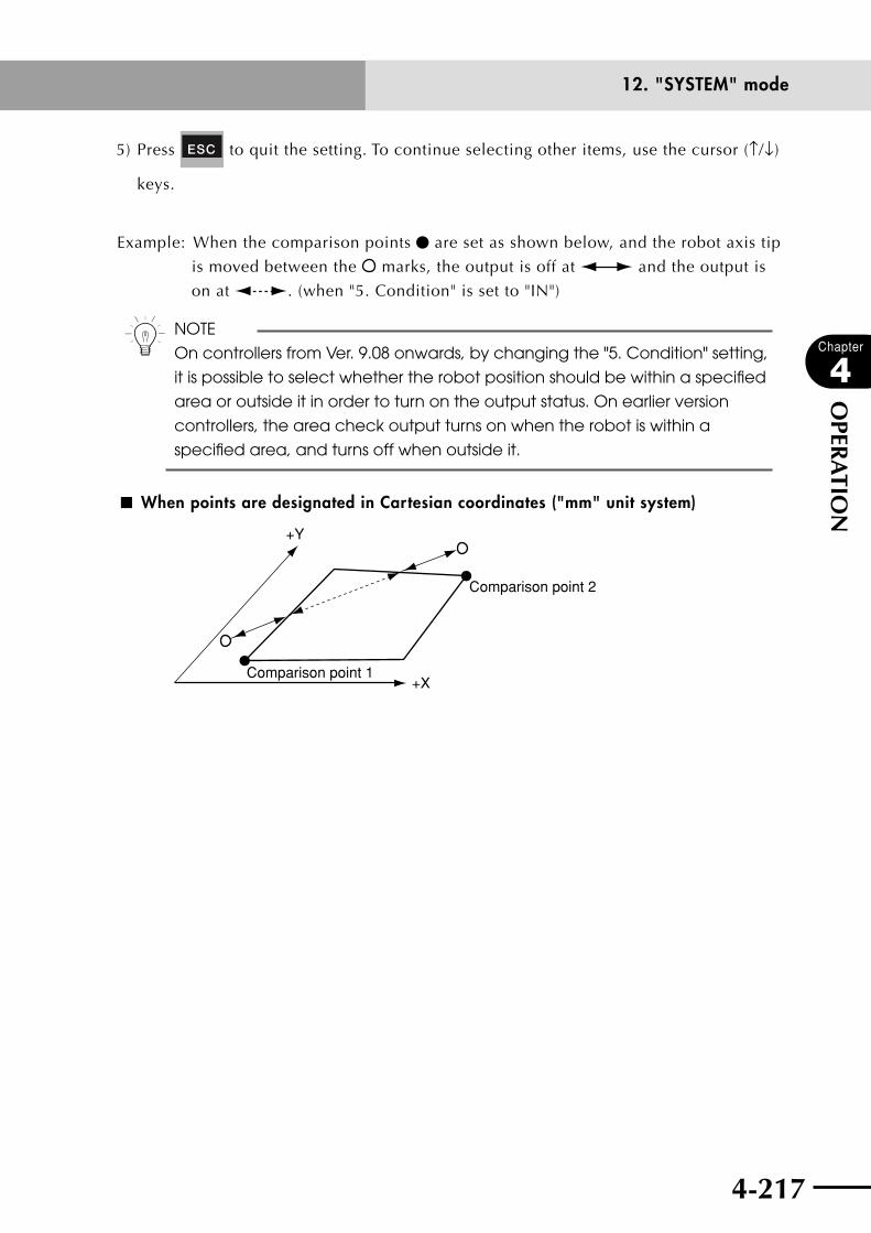
4-216 4-217
Chapter
4
OPER
ATIO
N
12. "SYSTEM" mode
5) Press to quit the setting. To continue selecting other items, use the cursor (↑/↓)
keys.
Example: When the comparison points are set as shown below, and the robot axis tip
is moved between the marks, the output is off at and the output is
on at . (when "5. Condition" is set to "IN")
n NOTE
On controllers from Ver. 9.08 onwards, by changing the "5. Condition" setting,
it is possible to select whether the robot position should be within a specified
area or outside it in order to turn on the output status. On earlier version
controllers, the area check output turns on when the robot is within a
specified area, and turns off when outside it.
■ When points are designated in Cartesian coordinates ("mm" unit system)
+X
+Y
Comparison point 2
Comparison point 1

4-218
Chapter
4
OPER
ATIO
N
4-219
12. "SYSTEM" mode
5. Condition for area check output
Selects the condition that allows the area check output to turn on, from either when
the robot is within a specified area or when outside it.
n NOTE
• ThisparameterissupportedbycontrollersofVer.9.08onwards.Onearlierversion controllers, the area check output turns on when the robot is within a specified area, and turns off when outside it.
• Anypointontheboundaryofthespecifiedareaisdeterminedtobewithin the area.
• Iftheareacheckcannotbeperformedcorrectlyduetoreturn-to-originincomplete, operation other than "MANUAL" or "AUTO" mode, or a memory error, then the area check output will turn off regardless of the criterion setting. If the specified port is the same as the port used by the program, then the area check output has priority.
• Thedefaultsettingis"IN"(outputisonwithinspecifiedarea).
[Procedure]
1) Select "5. Condition" in "SYSTEM>OPTION>POS.OUT>SELECT" mode.
2) Press (EDIT).
■ Criterion selection for area check output
SYSTEM>OPTION>POS.OUT>SELECT V9.08
1.Output of area1 MAIN
2.Output por1(DO & SO) 20
3.Compare Point number11 P1
4.Compare Point number12 P2
5.Condition IN
IN OUT
3) Select the criterion for area check output with (IN) or (OUT).
Setting Description
IN Turns on when the robot enters a specified area.
OUT Turns on when the robot goes out of a specified area.
4) Press to quit the setting. To continue selecting other items, use the cursor (↑/↓)
keys.
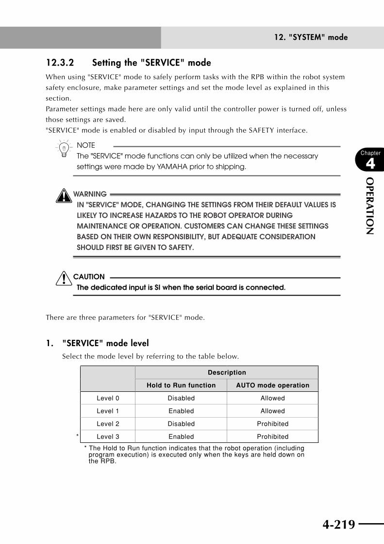
4-218 4-219
Chapter
4
OPER
ATIO
N
12. "SYSTEM" mode
12.3.2 Setting the "SERVICE" modeWhen using "SERVICE" mode to safely perform tasks with the RPB within the robot system
safety enclosure, make parameter settings and set the mode level as explained in this
section.
Parameter settings made here are only valid until the controller power is turned off, unless
those settings are saved.
"SERVICE" mode is enabled or disabled by input through the SAFETY interface.
n NOTE
The "SERVICE" mode functions can only be utilized when the necessary
settings were made by YAMAHA prior to shipping.
wWARNINGIN "SERVICE" MODE, CHANGING THE SETTINGS FROM THEIR DEFAULT VALUES IS LIkELY TO INCREASE HAzARDS TO THE ROBOT OPERATOR DURING MAINTENANCE OR OPERATION. CUSTOMERS CAN CHANGE THESE SETTINGS BASED ON THEIR OWN RESPONSIBILITY, BUT ADEqUATE CONSIDERATION SHOULD FIRST BE GIVEN TO SAFETY.
cCAUTIONThe dedicated input is SI when the serial board is connected.
There are three parameters for "SERVICE" mode.
1. "SERVICE" mode levelSelect the mode level by referring to the table below.
Description
Hold to Run function AUTO mode operation
Level 0 Disabled Allowed
Level 1 Enabled Allowed
Level 2 Disabled Prohibited
* Level 3 Enabled Prohibited
* The Hold to Run function indicates that the robot operation (including program execution) is executed only when the keys are held down on the RPB.

4-220
Chapter
4
OPER
ATIO
N
4-221
12. "SYSTEM" mode
2. Operating speed limits in "SERVICE" modeSpecify the maximum robot operating speed.
Description
* <3% Sets robot operation within 3 % of maximum operating speed.
<100% Sets no limit on robot operating speed.
* : These are default settings.
3. Operating device during "SERVICE" modeSpecify the operating device to use.
Description
* RPB Only RPB operation is allowed.
RPB/DI Allows RPB and dedicated input.
RPB/COM Allows RPB and online commands.
ALL Allows RPB, dedicated input and online command operation devices.
* : These are default settings.
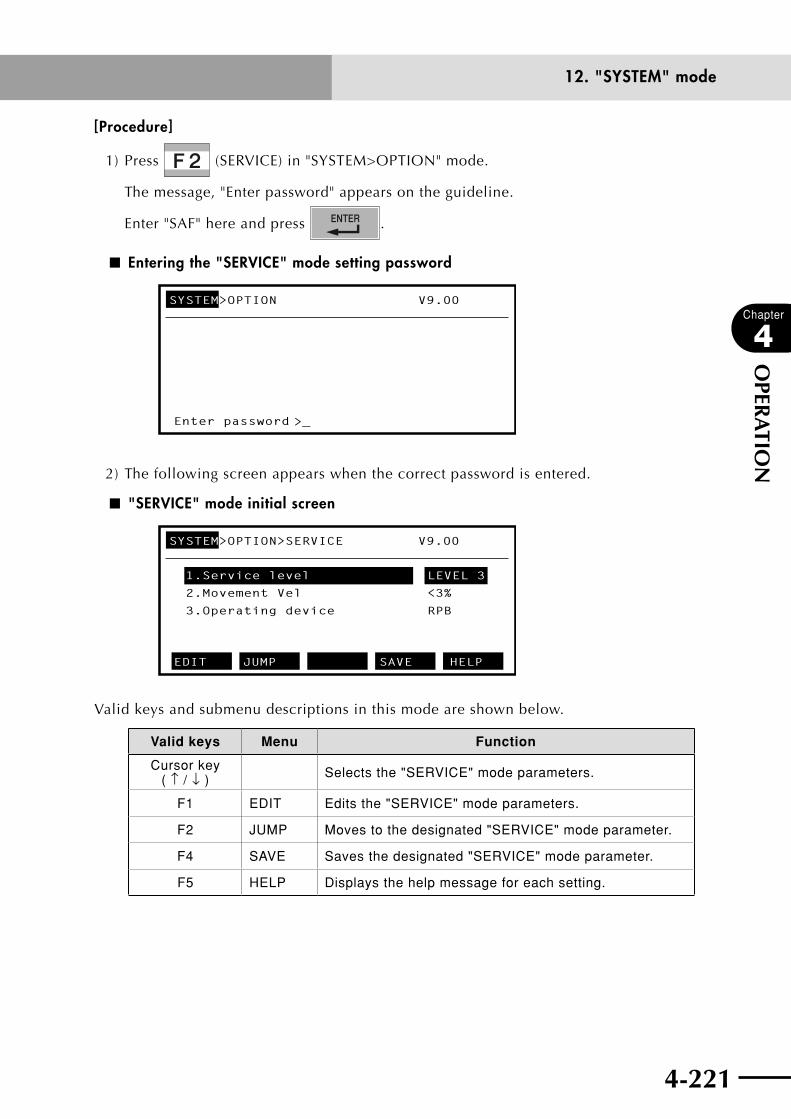
4-220 4-221
Chapter
4
OPER
ATIO
N
12. "SYSTEM" mode
[Procedure]
1) Press (SERVICE) in "SYSTEM>OPTION" mode.
The message, "Enter password" appears on the guideline.
Enter "SAF" here and press .
■ Entering the "SERVICE" mode setting password
SYSTEM>OPTION V9.00
Enter password >_
2) The following screen appears when the correct password is entered.
■ "SERVICE" mode initial screen
SYSTEM>OPTION>SERVICE V9.00
1.Service level
2.Movement Vel
<3%
3.Operating device
RPB
EDIT JUMP SAVE HELP
LEVEL 3
Valid keys and submenu descriptions in this mode are shown below.
Valid keys Menu Function
Cursor key ( ↑ / ↓ ) Selects the "SERVICE" mode parameters.
F1 EDIT Edits the "SERVICE" mode parameters.
F2 JUMP Moves to the designated "SERVICE" mode parameter.
F4 SAVE Saves the designated "SERVICE" mode parameter.
F5 HELP Displays the help message for each setting.
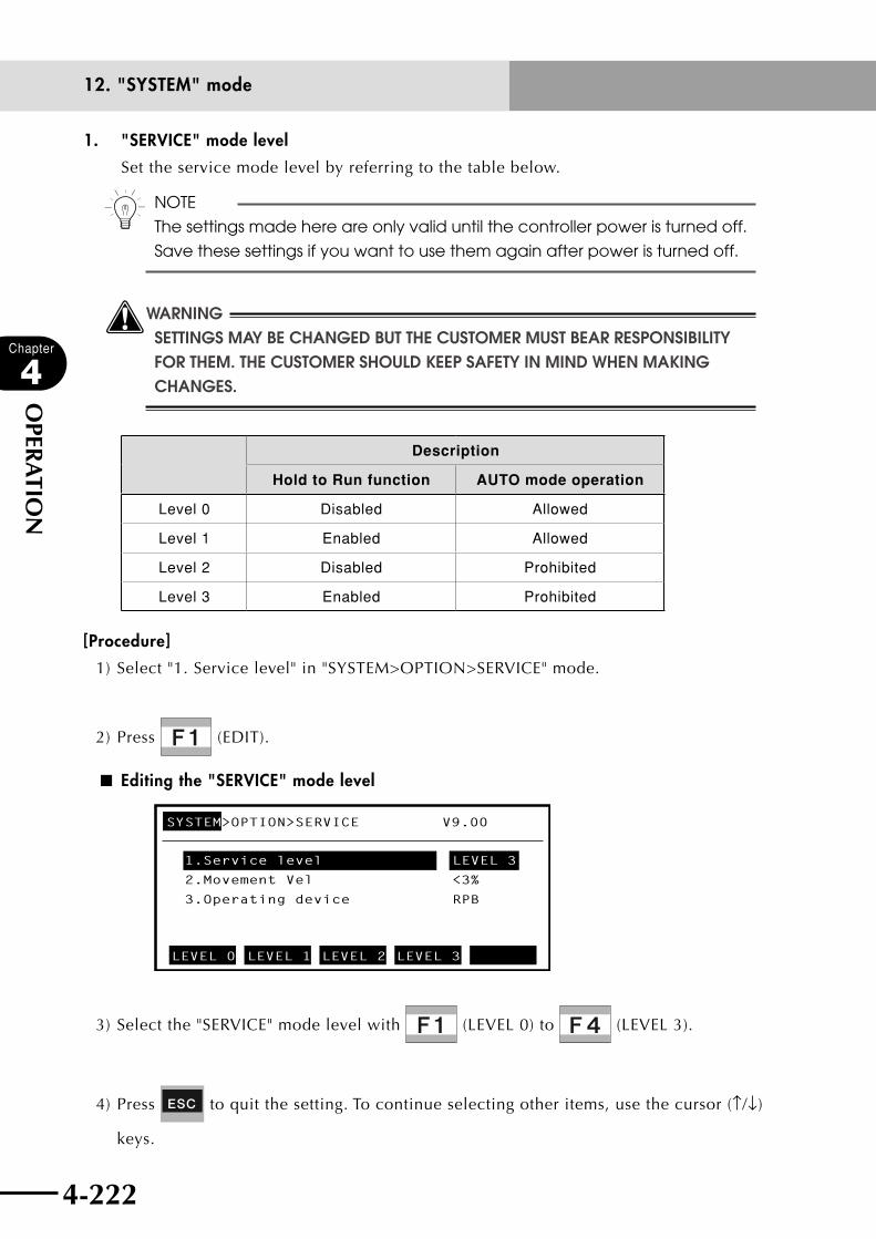
4-222
Chapter
4
OPER
ATIO
N
4-223
12. "SYSTEM" mode
1. "SERVICE" mode level
Set the service mode level by referring to the table below.
n NOTE
The settings made here are only valid until the controller power is turned off.
Save these settings if you want to use them again after power is turned off.
wWARNINGSETTINGS MAY BE CHANGED BUT THE CUSTOMER MUST BEAR RESPONSIBILITY FOR THEM. THE CUSTOMER SHOULD kEEP SAFETY IN MIND WHEN MAkING CHANGES.
Description
Hold to Run function AUTO mode operation
Level 0 Disabled Allowed
Level 1 Enabled Allowed
Level 2 Disabled Prohibited
Level 3 Enabled Prohibited
[Procedure]
1) Select "1. Service level" in "SYSTEM>OPTION>SERVICE" mode.
2) Press (EDIT).
■ Editing the "SERVICE" mode level
SYSTEM>OPTION>SERVICE V9.00
1.Service level
2.Movement Vel
<3%
3.Operating device
RPB
LEVEL 0 LEVEL 1 LEVEL 2 LEVEL 3
LEVEL 3
3) Select the "SERVICE" mode level with (LEVEL 0) to (LEVEL 3).
4) Press to quit the setting. To continue selecting other items, use the cursor (↑/↓)
keys.

4-222 4-223
Chapter
4
OPER
ATIO
N
12. "SYSTEM" mode
2. Operating speed limits in "SERVICE" mode
Specify the maximum robot operating speed.
n NOTE
The settings made here are only valid until the controller power is turned off.
Save these settings if you want to use them again after power is turned off.
wWARNINGSETTINGS MAY BE CHANGED BUT THE CUSTOMER MUST BEAR RESPONSIBILITY FOR THEM. THE CUSTOMER SHOULD kEEP SAFETY IN MIND WHEN MAkING CHANGES.
Description
<3% Sets robot operation within 3 % of maximum operating speed.
<100% Sets no limit on robot operating speed.
[Procedure]
1) Select "2. Movement Vel" in "SYSTEM>OPTION>SERVICE" mode.
2) Press (EDIT).
■ Editing the "SERVICE" mode operating speed
SYSTEM>OPTION>SERVICE V9.00
1.Service level
2.Movement Vel
3.Operating device
RPB
<100% <3%
LEVEL 3
<3%
3) Select the maximum robot operating speed with (<100%) or (<3%).
4) Press to quit the setting. To continue selecting other items, use the cursor (↑/↓)
keys.
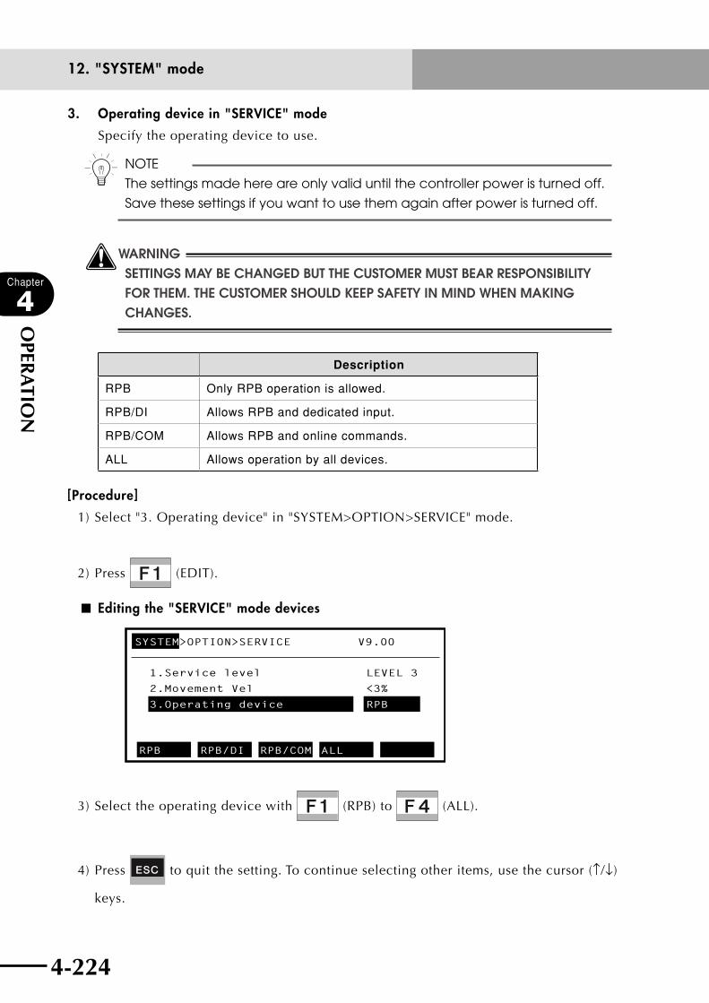
4-224
Chapter
4
OPER
ATIO
N
4-225
12. "SYSTEM" mode
3. Operating device in "SERVICE" mode
Specify the operating device to use.
n NOTE
The settings made here are only valid until the controller power is turned off.
Save these settings if you want to use them again after power is turned off.
wWARNINGSETTINGS MAY BE CHANGED BUT THE CUSTOMER MUST BEAR RESPONSIBILITY FOR THEM. THE CUSTOMER SHOULD kEEP SAFETY IN MIND WHEN MAkING CHANGES.
Description
RPB Only RPB operation is allowed.
RPB/DI Allows RPB and dedicated input.
RPB/COM Allows RPB and online commands.
ALL Allows operation by all devices.
[Procedure]
1) Select "3. Operating device" in "SYSTEM>OPTION>SERVICE" mode.
2) Press (EDIT).
■ Editing the "SERVICE" mode devices
SYSTEM>OPTION>SERVICE V9.00
1.Service level
2.Movement Vel
3.Operating device
RPB RPB/DI RPB/COM ALL
LEVEL 3
<3%
RPB
3) Select the operating device with (RPB) to (ALL).
4) Press to quit the setting. To continue selecting other items, use the cursor (↑/↓)
keys.

4-224 4-225
Chapter
4
OPER
ATIO
N
12. "SYSTEM" mode
12.3.2.1 Saving the "SERVICE" mode parameters
To save the parameter settings for "SERVICE" mode, follow the procedure below.
The parameter settings made here are only valid until the controller power is turned off,
unless you save those settings.
wWARNINGIN "SERVICE" MODE, CHANGING THE SETTINGS FROM THEIR DEFAULT VALUES IS LIkELY TO INCREASE HAzARDS TO THE ROBOT OPERATOR DURING MAINTENANCE OR OPERATION. CUSTOMERS CAN CHANGE THESE SETTINGS BASED ON THEIR OWN RESPONSIBILITY, BUT ADEqUATE CONSIDERATION SHOULD FIRST BE GIVEN TO SAFETY.
[Procedure]
1) Press (SAVE) in "SYSTEM>OPTION>SERVICE" mode.
When you have made changes to the parameters, a message appears on the guideline
asking if you want to save the setting.
■ Saving the "SERVICE" mode parameters
SYSTEM>OPTION>SERVICE V9.00
1.Service level
2.Movement Vel
<3%
3.Operating device
RPB
Change OK? YES NO
LEVEL 3
2) Press (YES) to save the setting.
Press (NO) if you want to cancel the settings.
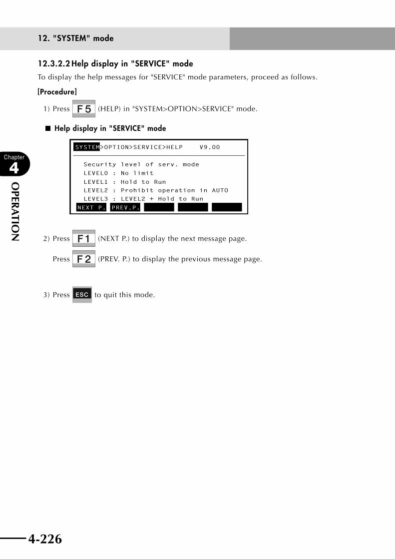
4-226
Chapter
4
OPER
ATIO
N
4-227
12. "SYSTEM" mode
12.3.2.2 Help display in "SERVICE" mode
To display the help messages for "SERVICE" mode parameters, proceed as follows.
[Procedure]
1) Press (HELP) in "SYSTEM>OPTION>SERVICE" mode.
■ Help display in "SERVICE" mode
SYSTEM>OPTION>SERVICE>HELP V9.00
Security level of serv. mode
LEVEL0 : No limit
LEVEL1 : Hold to Run
LEVEL2 : Prohibit operation in AUTO
LEVEL3 : LEVEL2 + Hold to Run
NEXT P. PREV.P.
2) Press (NEXT P.) to display the next message page.
Press (PREV. P.) to display the previous message page.
3) Press to quit this mode.

4-226 4-227
Chapter
4
OPER
ATIO
N
12. "SYSTEM" mode
12.3.3 SIO settingsThe serial I/O unit allows the master station sequencer (PLC) to send and receive parallel
port ON/OFF data in the robot controller I/O unit, regardless of the robot program. This
function allows using I/O devices such as sensors and relays as serial-connected devices.
n NOTE
• OutputresultsmightbeincorrectiftheSIOspecifiedportisthesameas
the port used by the program.
• ThesesettingsareonlyvalidwhentheserialI/Ounitisconnected.
■ SIO overview
Master stationPLC
CC-Link
Remote device station robot controller
I/O device(sensors, relays. etc.)
Parallel I/O connection
The relation between parallel and serial ports that can be set are shown below.
Input devices such as sensors Output devices such as valves
DI port → SO port DO port ← SI port
DI2() SO2() DO2() SI2()
DI3() SO3() DO3() SI3()
DI4() SO4() DO4() SI4()
DI5() SO5() DO5() SI5()
[Procedure]
1) Press (SIO) in "SYSTEM>OPTION" mode.
■ SIO setting initial screen
SYSTEM>OPTION>SIO V9.00
1.Direct SI2()->DO2() NO
2.Direct SI3()->DO3() NO
3.Direct SI4()->DO4() NO
4.Direct SI5()->DO5() NO
5.Direct SO2()<-DI2() NO
EDIT JUMP

4-228
Chapter
4
OPER
ATIO
N
4-229
12. "SYSTEM" mode
Valid keys and submenu descriptions in this mode are shown below.
Valid keys Menu Function
Cursor key ( ↑ / ↓ ) Selects the SIO parameter.
F1 EDIT Changes the SIO parameter.
F2 JUMP Moves the cursor to the designated SIO parameter.
1. Direct connection from SI n ( ) to DO n ( )
The serial port input can be directly connected to parallel port output. The relation
between parallel and serial ports that can be set is as follows.
n NOTE
Output results might be incorrect if the SIO specified port is the same as the
port used by the program.
Output devices such as valves
DO port ← SI port
DO2() SI2()
DO3() SI3()
DO4() SI4()
DO5() SI5()
[Procedure]
1) Select from 1 to 4 in "SYSTEM>OPTION>SIO" mode.
2) Press (EDIT).
■ Editing the SIO settings (1)
SYSTEM>OPTION>SIO V9.00
1.Direct SI2()->DO2() NO
2.Direct SI3()->DO3() NO
3.Direct SI4()->DO4() NO
4.Direct SI5()->DO5() NO
5.Direct SO2()<-DI2() NO
SET NO
3) Press (SET) to set the direct connection or press (NO) not to set it.
4) Press to quit the setting. To continue selecting other items, use the cursor (↑/↓)
keys.

4-228 4-229
Chapter
4
OPER
ATIO
N
12. "SYSTEM" mode
2. Direct connection from DI n ( ) to SO n ( )
Parallel port input can be directly connected to serial port output. The relation
between serial and parallel ports that can be set is as follows.
n NOTE
Output results might be incorrect if the SIO specified port is the same as the
port used by the program.
Input devices such as sensors
DI port → SO port
DI2() SO2()
DI3() SO3()
DI4() SO4()
DI5() SO5()
[Procedure]
1) Select from 5 to 8 in "SYSTEM>OPTION>SIO" mode.
2) Press (EDIT).
■ Editing the SIO settings (2)
SYSTEM>OPTION>SIO V9.00
4.Direct SI5()->DO5() NO
5.Direct SO2()<-DI2() NO
6.Direct SO3()<-DI3() NO
7.Direct SO4()<-DI4() NO
8.Direct SO5()<-DI5() NO
SET NO
3) Press (SET) to set the direct connection or press (NO) not to set it.
4) Press to quit the setting. To continue selecting other items, use the cursor (↑/↓)
keys.
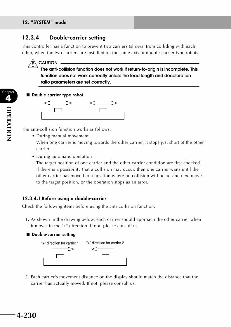
4-230
Chapter
4
OPER
ATIO
N
4-231
12. "SYSTEM" mode
12.3.4 Double-carrier settingThis controller has a function to prevent two carriers (sliders) from colliding with each
other, when the two carriers are installed on the same axis of double-carrier type robots.
cCAUTIONThe anti-collision function does not work if return-to-origin is incomplete. This function does not work correctly unless the lead length and deceleration ratio parameters are set correctly.
■ Double-carrier type robot
The anti-collision function works as follows:
•Duringmanualmovement
When one carrier is moving towards the other carrier, it stops just short of the other
carrier.
•Duringautomaticoperation
The target position of one carrier and the other carrier condition are first checked.
If there is a possibility that a collision may occur, then one carrier waits until the
other carrier has moved to a position where no collision will occur and next moves
to the target position, or the operation stops as an error.
12.3.4.1 Before using a double-carrier
Check the following items before using the anti-collision function.
1. As shown in the drawing below, each carrier should approach the other carrier when
it moves in the "+" direction. If not, please consult us.
■ Double-carrier setting
"+" direction for carrier 2"+" direction for carrier 1
2. Each carrier's movement distance on the display should match the distance that the
carrier has actually moved. If not, please consult us.
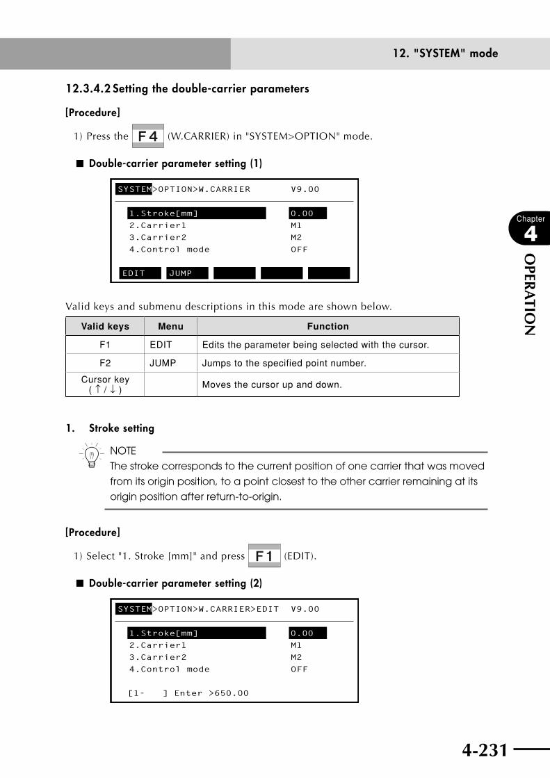
4-230 4-231
Chapter
4
OPER
ATIO
N
12. "SYSTEM" mode
12.3.4.2 Setting the double-carrier parameters
[Procedure]
1) Press the (W.CARRIER) in "SYSTEM>OPTION" mode.
■ Double-carrier parameter setting (1)
SYSTEM>OPTION>W.CARRIER V9.00
1.Stroke[mm] 0.00
2.Carrier1 M1
3.Carrier2 M2
4.Control mode OFF
EDIT JUMP
Valid keys and submenu descriptions in this mode are shown below.
Valid keys Menu Function
F1 EDIT Edits the parameter being selected with the cursor.
F2 JUMP Jumps to the specified point number.
Cursor key ( ↑ / ↓ ) Moves the cursor up and down.
1. Stroke setting
n NOTE
The stroke corresponds to the current position of one carrier that was moved
from its origin position, to a point closest to the other carrier remaining at its
origin position after return-to-origin.
[Procedure]
1) Select "1. Stroke [mm]" and press (EDIT).
■ Double-carrier parameter setting (2)
SYSTEM>OPTION>W.CARRIER>EDIT V9.00
1.Stroke[mm] 0.00
2.Carrier1 M1
3.Carrier2 M2
4.Control mode OFF
[1- ] Enter >650.00
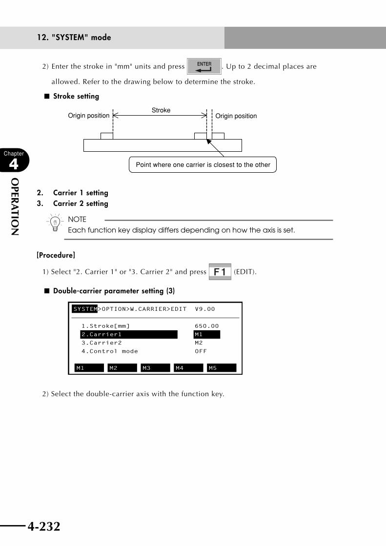
4-232
Chapter
4
OPER
ATIO
N
4-233
12. "SYSTEM" mode
2) Enter the stroke in "mm" units and press . Up to 2 decimal places are
allowed. Refer to the drawing below to determine the stroke.
■ Stroke setting
Origin position Origin position
Point where one carrier is closest to the other
Stroke
2. Carrier 1 setting 3. Carrier 2 setting
n NOTE
Each function key display differs depending on how the axis is set.
[Procedure]
1) Select "2. Carrier 1" or "3. Carrier 2" and press (EDIT).
■ Double-carrier parameter setting (3)
SYSTEM>OPTION>W.CARRIER>EDIT V9.00
1.Stroke[mm] 650.00
2.Carrier1 M1
3.Carrier2 M2
4.Control mode OFF
M1 M2 M3 M4 M5
2) Select the double-carrier axis with the function key.
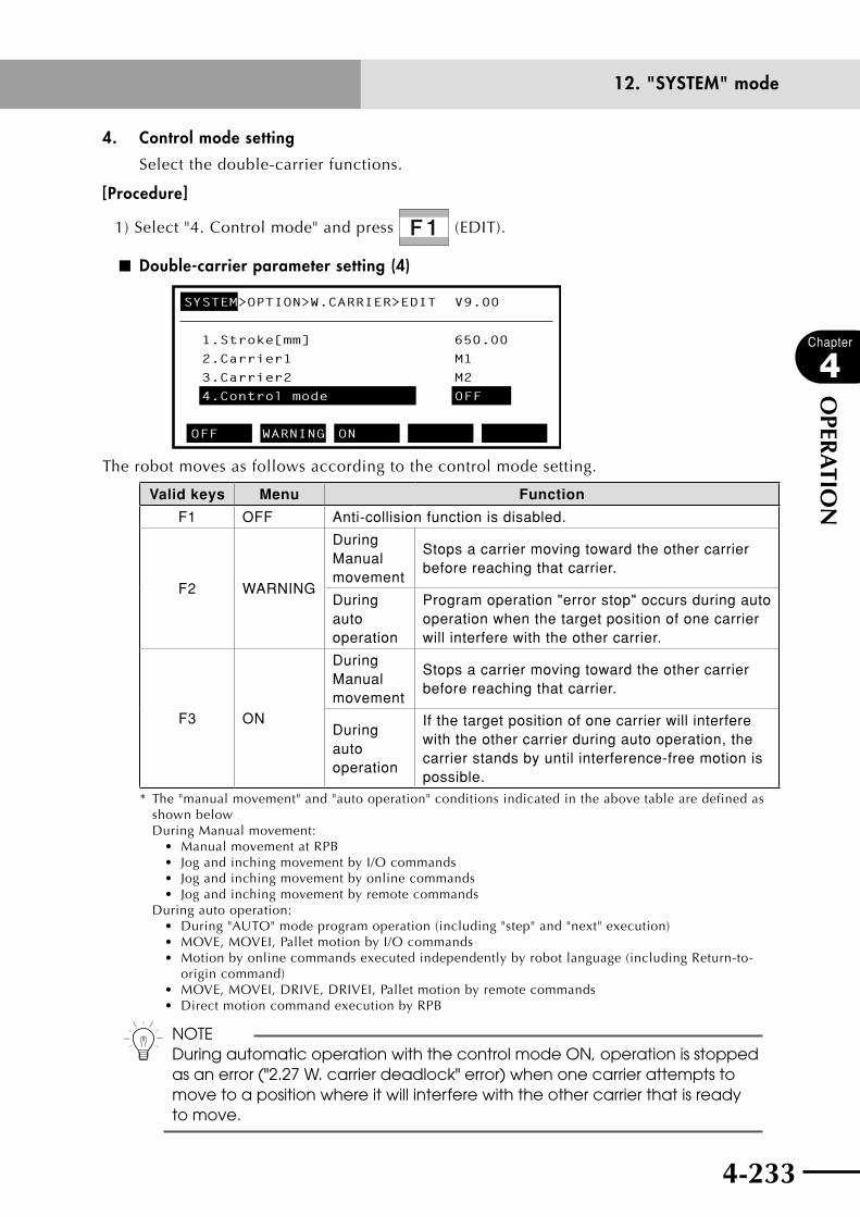
4-232 4-233
Chapter
4
OPER
ATIO
N
12. "SYSTEM" mode
4. Control mode setting
Select the double-carrier functions.
[Procedure]
1) Select "4. Control mode" and press (EDIT).
■ Double-carrier parameter setting (4)
SYSTEM>OPTION>W.CARRIER>EDIT V9.00
1.Stroke[mm] 650.00
2.Carrier1 M1
3.Carrier2 M2
4.Control mode OFF
OFF WARNING ON
The robot moves as follows according to the control mode setting.
Valid keys Menu Function
F1 OFF Anti-collision function is disabled.
F2 WARNING
During Manual movement
Stops a carrier moving toward the other carrier before reaching that carrier.
During auto operation
Program operation "error stop" occurs during auto operation when the target position of one carrier will interfere with the other carrier.
F3 ON
During Manual movement
Stops a carrier moving toward the other carrier before reaching that carrier.
During auto operation
If the target position of one carrier will interfere with the other carrier during auto operation, the carrier stands by until interference-free motion is possible.
* The "manual movement" and "auto operation" conditions indicated in the above table are defined as shown belowDuring Manual movement:
• ManualmovementatRPB• JogandinchingmovementbyI/Ocommands• Jogandinchingmovementbyonlinecommands• Jogandinchingmovementbyremotecommands
During auto operation:• During"AUTO"modeprogramoperation(including"step"and"next"execution)• MOVE,MOVEI,PalletmotionbyI/Ocommands• Motionbyonlinecommandsexecutedindependentlybyrobotlanguage(includingReturn-to- origin command)• MOVE,MOVEI,DRIVE,DRIVEI,Palletmotionbyremotecommands• DirectmotioncommandexecutionbyRPB
n NOTEDuring automatic operation with the control mode ON, operation is stopped as an error ("2.27 W. carrier deadlock" error) when one carrier attempts to move to a position where it will interfere with the other carrier that is ready to move.

4-234
Chapter
4
OPER
ATIO
N
4-235
12. "SYSTEM" mode
12.4 InitializationWhen initializing the parameter data you entered, follow the descriptions in this section.
[Procedure]
1) Press (INIT) in "SYSTEM" mode.
The initialization screen appears.
■ Initialization screen
SYSTEM>INIT V9.00
PARAM MEMORY CMU CLOCK
2) Select the item to initialize with (PARAM) to (CLOCK).
Valid keys and submenu descriptions in "SYSTEM>INT" mode are shown below.
Valid keys Menu Function
F1 PARAM Initializes the parameter settings.
F2 MEMORY Deletes the user memory.
F3 CMU Sets the communication parameters to the initial values.
F4 CLOCK Sets the clock.
F6 GENERAT Sets the robot model. (Normally invalid)
F10 PASSWRD Enables setting.
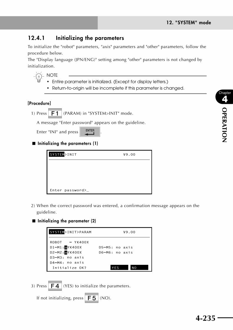
4-234 4-235
Chapter
4
OPER
ATIO
N
12. "SYSTEM" mode
12.4.1 Initializing the parametersTo initialize the "robot" parameters, "axis" parameters and "other" parameters, follow the
procedure below.
The "Display language (JPN/ENG)" setting among "other" parameters is not changed by
initialization.
n NOTE
• Entireparameterisinitialized.(Exceptfordisplayletters.)
• Return-to-originwillbeincompleteifthisparameterischanged.
[Procedure]
1) Press (PARAM) in "SYSTEM>INIT" mode.
A message "Enter password" appears on the guideline.
Enter "INI" and press .
■ Initializing the parameters (1)
SYSTEM>INIT V9.00
Enter password>_
2) When the correct password was entered, a confirmation message appears on the
guideline.
■ Initializing the parameter (2)
SYSTEM>INIT>PARAM V9.00
ROBOT = YK400X
D1=M1: aYK400X D5=M5: no axis
D2=M2: aYK400X D6=M6: no axis
no axis
no axis
D3=M3:
D4=M4:
Initialize OK? YES NO
3) Press (YES) to initialize the parameters.
If not initializing, press (NO).

4-236
Chapter
4
OPER
ATIO
N
4-237
12. "SYSTEM" mode
12.4.2 Initializing the memoryThis initializes the program, point data, shift coordinates, hand definitions and pallet
definitions.
Before initializing, make sure that the currently input data is no longer needed.
n NOTE
• Externaldatamustbeinputtorestorethememoryafterithasbeen
initialized.
• Thememorymustbeinitializedifdamagedduetosomekindofproblem.
[Procedure]
1) Press (MEMORY) in "SYSTEM>INIT" mode.
■ Initializing the memory
SYSTEM>INIT>MEMORY V9.00
Source(use/sum) = 1316/364580 bytes
Object(use/sum) = 528/ 98304 bytes
Sequence(use/sum)= 0/ 4096 bytes
Number of program = 5
Number of points = 124
PROGRAM POINT SHIFT HAND ALL
2) Select the item to initialize with (PROGRAM) to (COMMENT).
A confirmation message appears on the guideline.
■ Initializing the memory (program)
SYSTEM>INIT>MEMORY>PROGRAM V9.00
Source(use/sum) = 1316/364580 bytes
Object(use/sum) = 528/ 98304 bytes
Sequence(use/sum)= 0/ 4096 bytes
Number of program = 5
Number of points = 124
Initialize OK? YES NO
3) Press (YES) to initialize the memory.
If not initializing, press (NO).
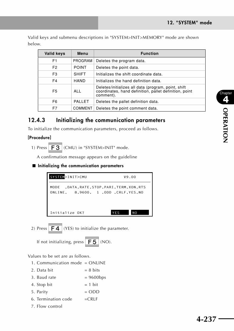
4-236 4-237
Chapter
4
OPER
ATIO
N
12. "SYSTEM" mode
Valid keys and submenu descriptions in "SYSTEM>INIT>MEMORY" mode are shown
below.
Valid keys Menu Function
F1 PROGRAM Deletes the program data.
F2 POINT Deletes the point data.
F3 SHIFT Initializes the shift coordinate data.
F4 HAND Initializes the hand definition data.
F5 ALLDeletes/initializes all data (program, point, shift coordinates, hand definition, pallet definition, point comment).
F6 PALLET Deletes the pallet definition data.
F7 COMMENT Deletes the point comment data.
12.4.3 Initializing the communication parametersTo initialize the communication parameters, proceed as follows.
[Procedure]
1) Press (CMU) in "SYSTEM>INIT" mode.
A confirmation message appears on the guideline
■ Initializing the communication parameters
SYSTEM>INIT>CMU V9.00
MODE ,DATA,RATE,STOP,PARI,TERM,XON,RTS
ONLINE, 8,9600, 1 ,ODD ,CRLF,YES,NO
Initialize OK? YES NO
2) Press (YES) to initialize the parameter.
If not initializing, press (NO).
Values to be set are as follows.
1. Communication mode = ONLINE
2. Data bit = 8 bits
3. Baud rate = 9600bps
4. Stop bit = 1 bit
5. Parity = ODD
6. Termination code =CRLF
7. Flow control

4-238
Chapter
4
OPER
ATIO
N
4-239
12. "SYSTEM" mode
12.4.4 Clock settingA clock function is provided in the controller for setting the date and time.
cCAUTIONThe clock used in the controller might differ from the correct time. If this happens, set the correct time.
[Procedure]
1) Press (CLOCK) in "SYSTEM>INIT" mode.
The present date and time are displayed.
■ Initializing the clock
SYSTEM>INIT>CLOCK V9.00
DATE,TIME :06/06/01,10:13:35
DATE TIME
2) Select the item with (DATE) or (TIME).
A confirmation message appears on the guideline.
3) Enter the date or time in the specified format and then press .
Enter this data using to , and .
Valid keys Menu Function
F1 DATE Sets the year/month/day.
F2 TIME Sets the hours/minutes/seconds.
4-238 4-239
Chapter
4
OPER
ATIO
N
12. "SYSTEM" mode
12.4.5 System generationIn system generation in the robot controller, the specifications for the robot being
connected and the axis configurations are set prior to shipment. The user does not
normally need to set the system generation with (GENERAT) in "SYSTEM>INIT"
mode.
Should the memory for the system generation be destroyed by some serious problem the
user must make the correct system generation settings. To protect the equipment against
such accidents, save the initial parameter data when shipped from YAMAHA and the
parameter data from system upgrades onto an external PC storage device by way of the
RS-232C.
Please contact us for system generation operating methods.
cCAUTION• ifyouchangethesystemgenerationbymistake,thismayadversely
affect robot operation or create hazards to operators. Always consult YAMAHA if changes have been made.
• pleasenotethatYAMAHAcannotbeliableforproblemsresultingfromchanging the system generation settings without first consulting YAMAHA.
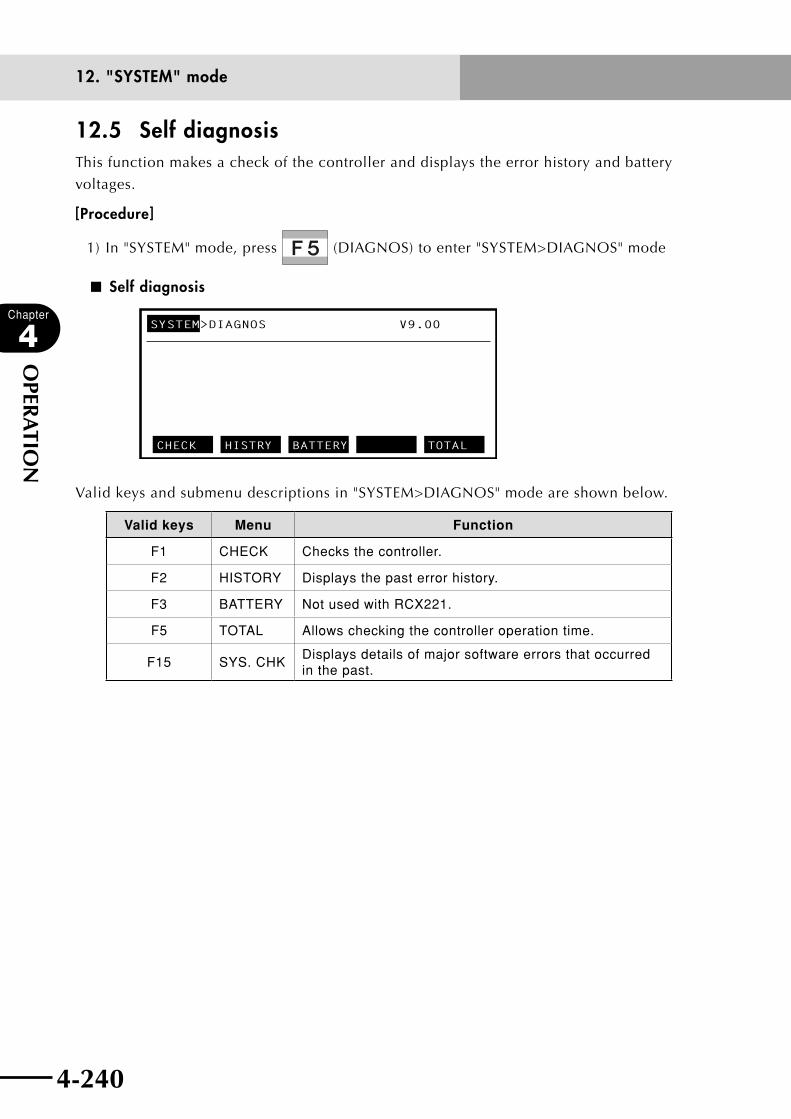
4-240
Chapter
4
OPER
ATIO
N
4-241
12. "SYSTEM" mode
12.5 Self diagnosisThis function makes a check of the controller and displays the error history and battery
voltages.
[Procedure]
1) In "SYSTEM" mode, press (DIAGNOS) to enter "SYSTEM>DIAGNOS" mode
■ Self diagnosis
SYSTEM>DIAGNOS V9.00
CHECK HISTRY BATTERY TOTAL
Valid keys and submenu descriptions in "SYSTEM>DIAGNOS" mode are shown below.
Valid keys Menu Function
F1 CHECK Checks the controller.
F2 HISTORY Displays the past error history.
F3 BATTERY Not used with RCX221.
F5 TOTAL Allows checking the controller operation time.
F15 SYS. CHKDisplays details of major software errors that occurred in the past.

4-240 4-241
Chapter
4
OPER
ATIO
N
12. "SYSTEM" mode
12.5.1 Controller checkThis makes a self-diagnosis check of the controller.
n NOTE
• AnerrormessagewillalwaysappearifDC24VisnotsuppliedtoSTD.DIO.
• AnerrormessagewillalwaysappearifDC24Visnotsuppliedtothe
option DIO.
[Procedure]
1) Press (CHECK) to enter "SYSTEM>DIAGNOS>CHECK" mode.
■ System check
SYSTEM>DIAGNOS>CHECK V9.00
System check OK !!
NEXT P. PREV.P.
An error message appears if an error is detected.
2) Check the error message if displayed.
Pressing the cursor (↑/↓) keys changes the display one line at a time.
Pressing (NEXT P.) or (PREV. P.) changes the display one screen at a
time.
3) Press to return to "SYSTEM>DIAGNOS" mode.

4-242
Chapter
4
OPER
ATIO
N
4-243
12. "SYSTEM" mode
12.5.2 Error history displayTo display past errors that occurred, follow the procedure below. A maximum of 500 items
may be stored in the error history.
cCAUTION• errorsarenotrecordedwhenidenticaltoaprecedingerrorthatjust
occurred.• theerrorcategory"0"isnotrecorded.
• theerrorhistoryisinitializedwhen (CLEAR) is used. Do not initialize
if you want to retain the error history.
[Procedure]
1) Press (HISTRY) to enter "SYSTEM>DIAGNOS> HISTRY" mode.
■ Error history
SYSTEM>DIAGNOS>HISTRY V9.00
1:06/06/01,10:15:00 12.1:Emg.stop on
2:06/06/01,10:14:54 22.1:AC power low
3:06/06/01,09:59:34 17.4:D1,Over load
4:06/06/28,14:00:02 12.1:Emg.stop on
5:06/06/30,08:40:10 22.1:AC power low
NEXT P. PREV.P. CLEAR
One screen displays the past 5 errors in order from the most recent error.
Error information is displayed in the following format.
<Date>, <Time> <Error No.>:<Error message>
* The hour, minute and second are displayed for the time.
2) Check the error history.
Pressing the cursor (↑/↓) keys changes the display one line at a time.
Pressing (NEXT P.) or (PREV. P.) changes the display one screen at a
time.
3) Press (CLEAR) if you want to clear the error history.
4) Press to return to "SYSTEM>DIAGNOS" mode.
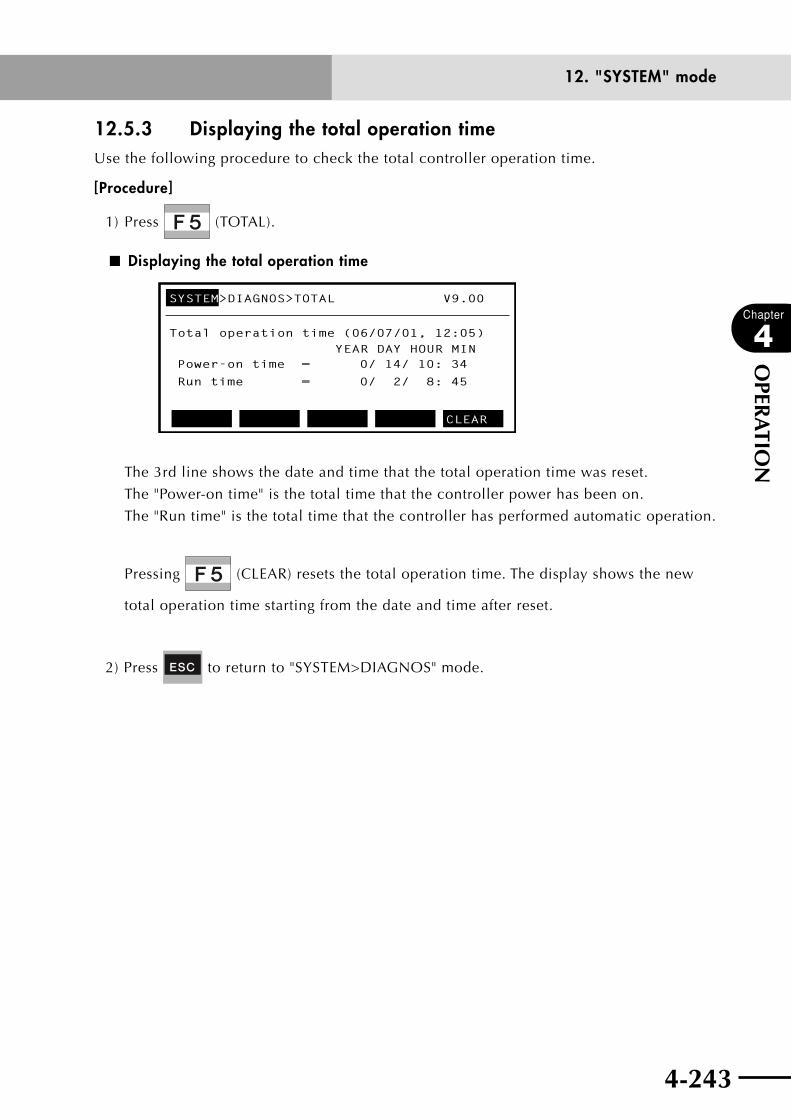
4-242 4-243
Chapter
4
OPER
ATIO
N
12. "SYSTEM" mode
12.5.3 Displaying the total operation timeUse the following procedure to check the total controller operation time.
[Procedure]
1) Press (TOTAL).
■ Displaying the total operation time
SYSTEM>DIAGNOS>TOTAL V9.00
Total operation time (06/07/01, 12:05) YEAR DAY HOUR MIN
CLEAR
Power-on time = 0/ 14/ 10: 34Run time = 0/ 2/ 8: 45
The 3rd line shows the date and time that the total operation time was reset.
The "Power-on time" is the total time that the controller power has been on.
The "Run time" is the total time that the controller has performed automatic operation.
Pressing (CLEAR) resets the total operation time. The display shows the new
total operation time starting from the date and time after reset.
2) Press to return to "SYSTEM>DIAGNOS" mode.
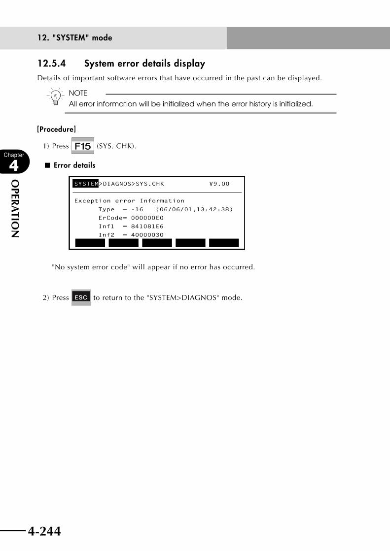
4-244
Chapter
4
OPER
ATIO
N
4-245
12. "SYSTEM" mode
12.5.4 System error details displayDetails of important software errors that have occurred in the past can be displayed.
n NOTE
All error information will be initialized when the error history is initialized.
[Procedure]
1) Press (SYS. CHK).
■ Error details
SYSTEM>DIAGNOS>SYS.CHK V9.00
Exception error Information
Type = -16 (06/06/01,13:42:38)
ErCode= 000000E0
Inf1 = 841081E6
Inf2 = 40000030
"No system error code" will appear if no error has occurred.
2) Press to return to the "SYSTEM>DIAGNOS" mode.

4-244 4-245
Chapter
4
OPER
ATIO
N
12. "SYSTEM" mode
12.6 Backup processesThe various data in the controller's internal memory can be backed up in the internal flash
ROM or the SD memory card.
[Procedure]
1) Press (BACKUP) in the "SYSTEM" mode.
■ Backup
SYSTEM>BACKUP V9.00
SD CARD FROM
Valid keys and submenu descriptions in "SYSTEM>BACKUP" mode are shown below.
Valid keys Menu Function
F4 SD CARD Saves or restores data using an SD memory.
F5 FROM Saves or restores data using the internal flash ROM.

4-246
Chapter
4
OPER
ATIO
N
4-247
12. "SYSTEM" mode
12.6.1 SD memory cardData in the controller can be saved on an SD memory card. The data can then be loaded
into the controller from the SD memory card.
cCAUTIONDo not remove the SD memory card while data is being saved on it or loaded from it. Removing the card at that time might corrupt the data.
n NOTE
This controller allows handling subdirectories down to 8 levels of hierarchy
below the root directory. Operation to a subdirectory lower than this level is
not allowed.
n NOTE
This controller supports only FAT12 and FAT16 file systems. If the files were
created on a PC, then the file names might differ from those displayed on
the PC.
[Inserting the SD memory card]
Insert an SD memory card into the SD memory card slot on the front of the controller
until you hear a "click", while making sure the card is facing correctly (see below).
■ Inserting the SD memory card
YM
N
L
L1
N1
SAFETY
RPB
SD/COM
EXT.E-STOP
PIN11-12
OP.2
!
SD
MEMO
RYC
AR
D
SD memory card
[Removing the SD memory card]
Press in on the SD memory card installed in the slot until you hear a "click". The card
will then eject from the slot, so take it out of the slot.

4-246 4-247
Chapter
4
OPER
ATIO
N
12. "SYSTEM" mode
[Procedure]
1) Press (SD CARD) in "SYSTEM>BACKUP" mode.
When the SD memory card is inserted in the slot, information on files stored on the
SD memory card is displayed. If no SD memory card is inserted, a "15.21: Cannot find
media" error occurs.
■ SD memory card (1)
SD:\
FILE1 .ALL 102520 06/04/07 13:30
FILE2 .PGM 8528 06/04/12 17:07
SUBDIR . <DIR> 06/03/27 15:21
FILE3 .PNT 1741 06/04/21 10:45
SYSTEM>BACKUP>SDCARD V9.00
LOAD SAVE INIT
2) The path to the currently displayed directory is shown in the 3rd line.
3) Files or subdirectory in the directory are shown in the 4th to 7th lines.
4) Move the cursor with the cursor up/down (↑/↓) keys.
Valid keys and submenu descriptions in "SYSTEM>BACKUP>SD CARD" mode are shown
below.
Valid keys Menu Function
F1 LOADLoads the file selected by the cursor or moves to a
subdirectory when it is selected.
F2 SAVE Saves the controller's data.
F5 BACKMoves to the directory one level above the current
directory.
F6 DELDeletes the selected file. Cannot delete any
subdirectory.
F8 PREVIEW Displays the content (part) of the selected file.
Exits SD CARD mode.

4-248
Chapter
4
OPER
ATIO
N
4-249
12. "SYSTEM" mode
12.6.1.1 Loading files
Data stored on an SD memory card can be loaded back into the controller's internal
memory.
cCAUTIONDo not remove the SD memory card while data is being loaded from it.
n NOTE
With a subdirectory selected, pressing (LOAD) will move to that
subdirectory.
[Procedure]
1) In the "SYSTEM>BACKUP>SD CARD" mode, select the file to be loaded using the
cursor up/down (↑/↓) keys.
2) Press (LOAD).
3) A confirmation message appears.
Press (YES) to load the file.
Press (NO) to cancel.
■ Loading a file
SD:\
FILE1 .ALL 102520 06/04/07 13:30
FILE2 .PGM 8528 06/04/12 17:07
SUBDIR . <DIR> 06/03/27 15:21
FILE3 .PNT 1741 06/04/21 10:45
SYSTEM>BACKUP>SDCARD V9.00
Load from SDCARD OK? YES NO
4) The message "0.5: Accessing" will appear during loading.
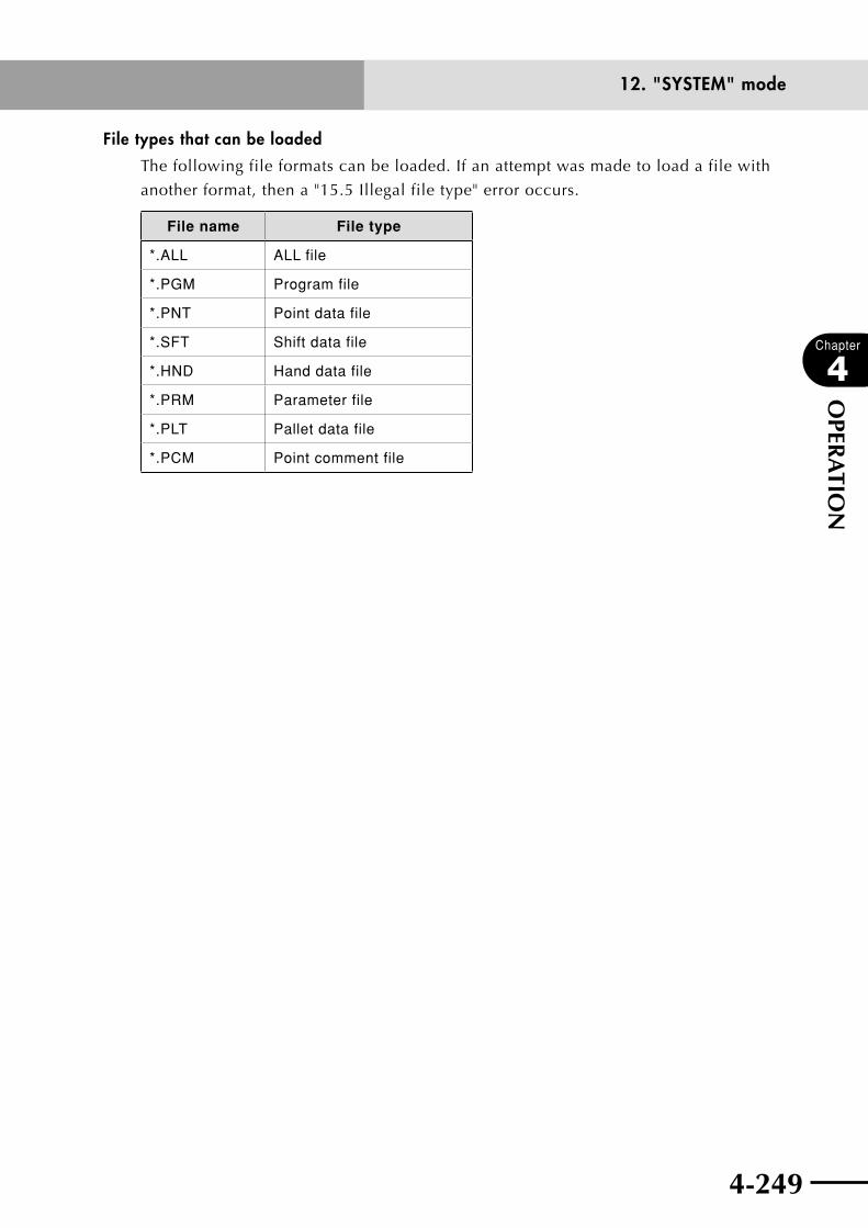
4-248 4-249
Chapter
4
OPER
ATIO
N
12. "SYSTEM" mode
File types that can be loaded
The following file formats can be loaded. If an attempt was made to load a file with
another format, then a "15.5 Illegal file type" error occurs.
File name File type
*.ALL ALL file
*.PGM Program file
*.PNT Point data file
*.SFT Shift data file
*.HND Hand data file
*.PRM Parameter file
*.PLT Pallet data file
*.PCM Point comment file
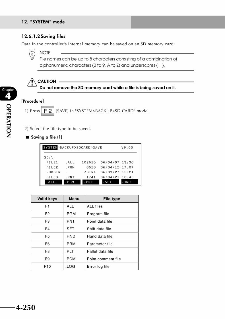
4-250
Chapter
4
OPER
ATIO
N
4-251
12. "SYSTEM" mode
12.6.1.2 Saving files
Data in the controller's internal memory can be saved on an SD memory card.
n NOTE
File names can be up to 8 characters consisting of a combination of
alphanumeric characters (0 to 9, A to Z) and underscores ( _ ).
cCAUTIONDo not remove the SD memory card while a file is being saved on it.
[Procedure]
1) Press (SAVE) in "SYSTEM>BACKUP>SD CARD" mode.
2) Select the file type to be saved.
■ Saving a file (1)
SD:\
FILE1 .ALL 102520 06/04/07 13:30
FILE2 .PGM 8528 06/04/12 17:07
SUBDIR . <DIR> 06/03/27 15:21
FILE3 .PNT 1741 06/04/21 10:45
SYSTEM>BACKUP>SDCARD>SAVE V9.00
.ALL .PGM .PNT .SFT .HND
Valid keys Menu File type
F1 .ALL ALL files
F2 .PGM Program file
F3 .PNT Point data file
F4 .SFT Shift data file
F5 .HND Hand data file
F6 .PRM Parameter file
F8 .PLT Pallet data file
F9 .PCM Point comment file
F10 .LOG Error log file
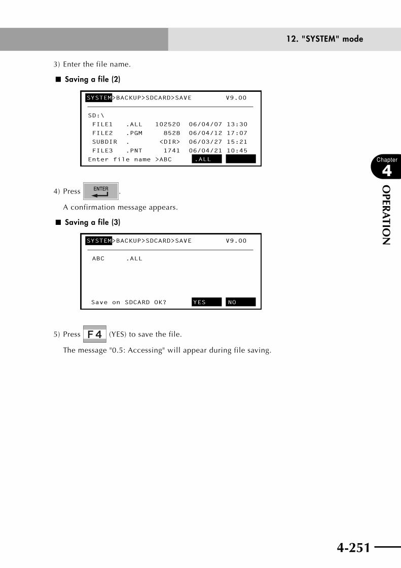
4-250 4-251
Chapter
4
OPER
ATIO
N
12. "SYSTEM" mode
3) Enter the file name.
■ Saving a file (2)
SD:\
FILE1 .ALL 102520 06/04/07 13:30
FILE2 .PGM 8528 06/04/12 17:07
SUBDIR . <DIR> 06/03/27 15:21
FILE3 .PNT 1741 06/04/21 10:45
Enter file name >ABC
SYSTEM>BACKUP>SDCARD>SAVE V9.00
.ALL
4) Press .
A confirmation message appears.
■ Saving a file (3)
ABC .ALL
SYSTEM>BACKUP>SDCARD>SAVE V9.00
Save on SDCARD OK? YES NO
5) Press (YES) to save the file.
The message "0.5: Accessing" will appear during file saving.
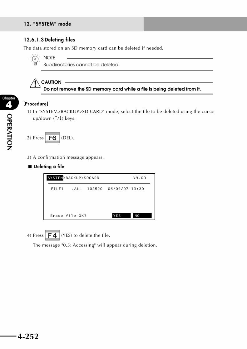
4-252
Chapter
4
OPER
ATIO
N
4-253
12. "SYSTEM" mode
12.6.1.3 Deleting files
The data stored on an SD memory card can be deleted if needed.
n NOTE
Subdirectories cannot be deleted.
cCAUTIONDo not remove the SD memory card while a file is being deleted from it.
[Procedure]
1) In "SYSTEM>BACKUP>SD CARD" mode, select the file to be deleted using the cursor
up/down (↑/↓) keys.
2) Press (DEL).
3) A confirmation message appears.
■ Deleting a file
FILE1 .ALL 102520 06/04/07 13:30
SYSTEM>BACKUP>SDCARD V9.00
Erase file OK? YES NO
4) Press (YES) to delete the file.
The message "0.5: Accessing" will appear during deletion.
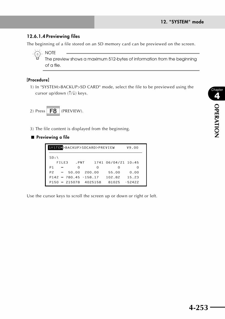
4-252 4-253
Chapter
4
OPER
ATIO
N
12. "SYSTEM" mode
12.6.1.4 Previewing files
The beginning of a file stored on an SD memory card can be previewed on the screen.
n NOTE
The preview shows a maximum 512-bytes of information from the beginning
of a file.
[Procedure]
1) In "SYSTEM>BACKUP>SD CARD" mode, select the file to be previewed using the
cursor up/down (↑/↓) keys.
2) Press (PREVIEW).
3) The file content is displayed from the beginning.
■ Previewing a file
SD:\
FILE3 .PNT 1741 06/04/21 10:45
P1 = 0 0 0 0
P2 = 50.00 200.00 55.00 0.00
P142 = 780.45 -158.17 102.82 15.23
P150 = 215078 4025158 81025 -52422
SYSTEM>BACKUP>SDCARD>PREVIEW V9.00
Use the cursor keys to scroll the screen up or down or right or left.
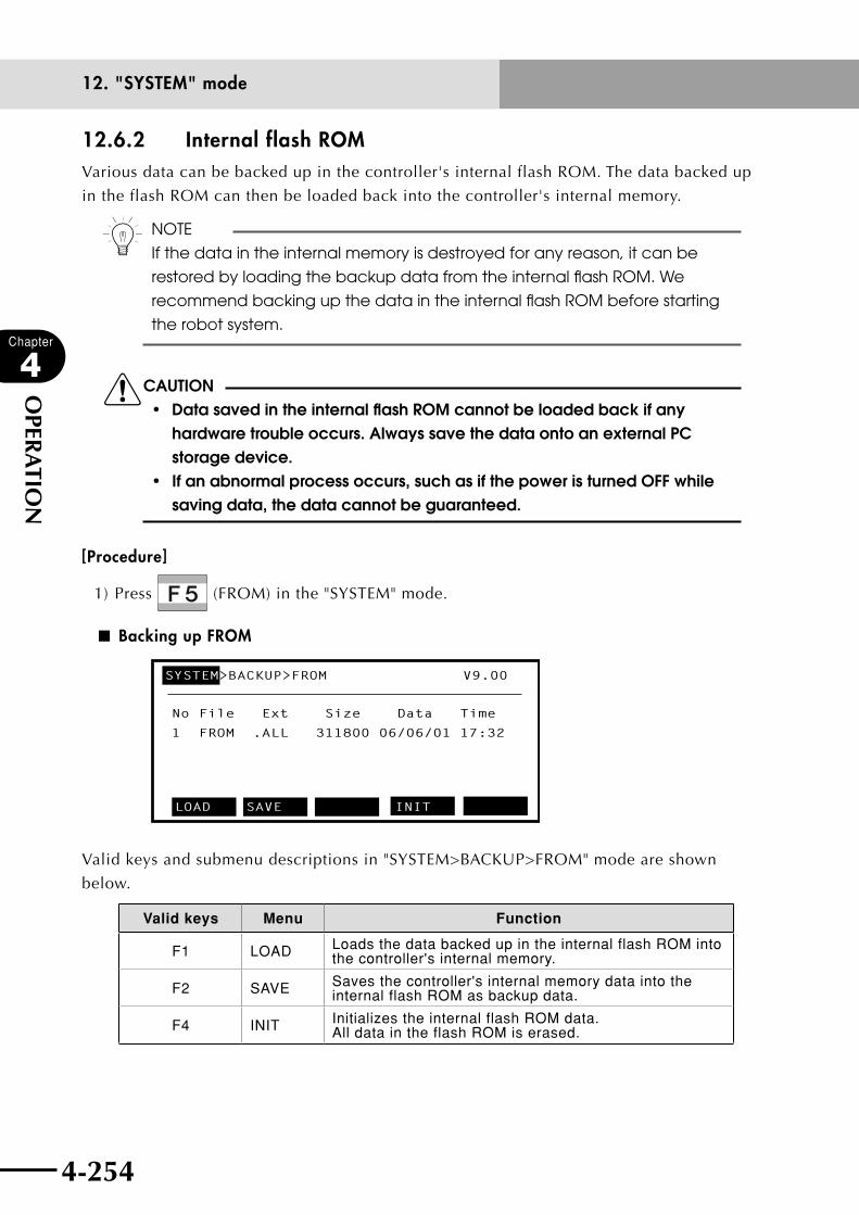
4-254
Chapter
4
OPER
ATIO
N
4-255
12. "SYSTEM" mode
12.6.2 Internal flash ROMVarious data can be backed up in the controller's internal flash ROM. The data backed up
in the flash ROM can then be loaded back into the controller's internal memory.
n NOTE
If the data in the internal memory is destroyed for any reason, it can be
restored by loading the backup data from the internal flash ROM. We
recommend backing up the data in the internal flash ROM before starting
the robot system.
cCAUTION• datasavedintheinternalflashroMcannotbeloadedbackifany
hardware trouble occurs. Always save the data onto an external PC storage device.
• ifanabnormalprocessoccurs,suchasifthepoweristurnedoffwhilesaving data, the data cannot be guaranteed.
[Procedure]
1) Press (FROM) in the "SYSTEM" mode.
■ Backing up FROM
No File Ext Size Data Time
1 FROM .ALL 311800 06/06/01 17:32
SYSTEM>BACKUP>FROM V9.00
LOAD SAVE INIT
Valid keys and submenu descriptions in "SYSTEM>BACKUP>FROM" mode are shown
below.
Valid keys Menu Function
F1 LOAD Loads the data backed up in the internal flash ROM into the controller's internal memory.
F2 SAVE Saves the controller's internal memory data into the internal flash ROM as backup data.
F4 INIT Initializes the internal flash ROM data. All data in the flash ROM is erased.

4-254 4-255
Chapter
4
OPER
ATIO
N
12. "SYSTEM" mode
12.6.2.1 Loading files
The various data backed up in the controller's internal flash ROM can be loaded back into
the controller's internal memory.
n NOTE
If the data in the internal memory is destroyed for any reason, it can be
restored by loading the backup data from the internal flash ROM. We
recommend backing up the data in the internal flash ROM before starting
the robot system.
cCAUTION• whenreadingdatawithAllfilesorasparameterfiles,theservomustbe
off. After the files are read in, the return-to-origin incomplete state will be set.
• datasavedintheinternalflashroMcannotbeloadedbackifanyhardware trouble occurs. Always save the data onto an external PC storage device.
• ifanabnormalprocessoccurs,suchasifthepoweristurnedoffwhilesaving data, the data cannot be guaranteed.
[Procedure]
1) Press (LOAD) in the "SYSTEM>BACKUP>FROM" mode.
The types of files will appear in the guideline.
2) Select the file type to be loaded with (.ALL) to (.PCM).
■ Loading FROM
No File Ext Size Data Time
1 FROM .ALL 311800 06/06/01 17:32
SYSTEM>BACKUP>FROM>LOAD V9.00
.ALL .PGM .PNT .SFT .HND

4-256
Chapter
4
OPER
ATIO
N
4-257
12. "SYSTEM" mode
Valid keys and submenu descriptions in "SYSTEM>BACKUP>FROM>LOAD" mode are
shown below.
Valid keys Menu Function
F1 .ALL Files are loaded as ALL files.
F2 .PGM Only program files are loaded.
F3 .PNT Only point files are loaded.
F4 .SFT Only shift files are loaded.
F5 .HND Only hand files are loaded.
F6 .PRM Only parameter files are loaded.
F8 .PLT Only pallet files are loaded.
F9 .PCM Only point comment files are loaded.
3) A confirmation message appears on the guidelines.
Press (YES) to load the data.
Press (NO) to cancel the procedure.
■ Check of FROM loading
No File Ext Size Data Time
1 FROM .ALL 311800 06/06/01 17:32
SYSTEM>BACKUP>FROM>LOAD>.PGM V9.00
Load from FROM OK? YES NO
4) The message "0.5: Accessing" will appear during the procedure.

4-256 4-257
Chapter
4
OPER
ATIO
N
12. "SYSTEM" mode
12.6.2.2 Saving files
The data in the controller's internal memory are saved as ALL files on the flash ROM. The
data cannot be saved separately. If data is already saved, the new data cannot be saved
until the files are initialized.
n NOTE
If the data in the internal memory is destroyed for any reason, it can be restored by loading the backup data from the internal flash ROM. We recommend backing up the data in the internal flash ROM before starting the robot system.
cCAUTION• ifdatahasalreadybeenwrittenin,itcannotbeoverwrittenandsaved.
If data has already been written in, initialize the memory, and then save the new data.
• thedatasavedontheinternalflashroMcannotberestoredifanyhardware trouble occurs. Always save the data onto an external PC storage device.
• ifanabnormalprocessoccurs,suchasifthepoweristurnedoffwhilesaving the data, the data cannot be guaranteed.
• the"skipundefinedparameters"settingamong"other"parameterswillnot be saved.
[Procedure]
1) Press (SAVE) in the "SYSTEM>BACKUP>FROM" mode.
2) A confirmation message appears on the guidelines.
Press (YES) to save the data.
Press (NO) to cancel the procedure.
■ Check of saving on FROM
No File Ext Size Data Time
1 No data
SYSTEM>BACKUP>FROM>SAVE V9.00
Save on FROM OK? YES NO
3) The message "0.5: Accessing" will appear during the procedure.
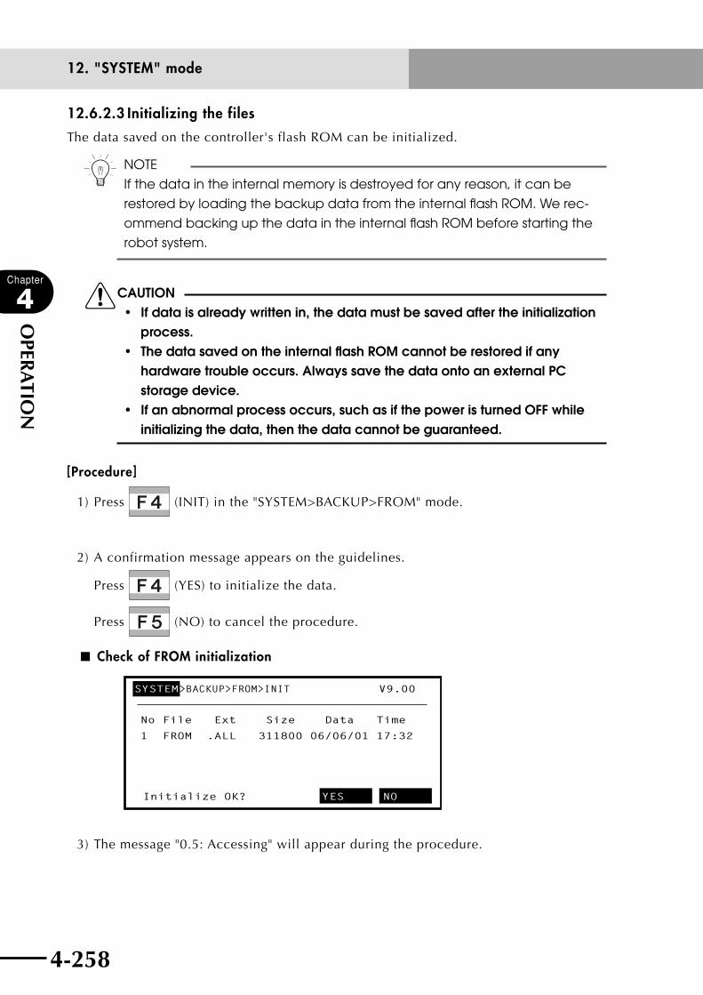
4-258
Chapter
4
OPER
ATIO
N
12. "SYSTEM" mode
12.6.2.3 Initializing the files
The data saved on the controller's flash ROM can be initialized.
n NOTE
If the data in the internal memory is destroyed for any reason, it can be
restored by loading the backup data from the internal flash ROM. We rec-
ommend backing up the data in the internal flash ROM before starting the
robot system.
cCAUTION• ifdataisalreadywrittenin,thedatamustbesavedaftertheinitialization
process.• thedatasavedontheinternalflashroMcannotberestoredifany
hardware trouble occurs. Always save the data onto an external PC storage device.
• ifanabnormalprocessoccurs,suchasifthepoweristurnedoffwhileinitializing the data, then the data cannot be guaranteed.
[Procedure]
1) Press (INIT) in the "SYSTEM>BACKUP>FROM" mode.
2) A confirmation message appears on the guidelines.
Press (YES) to initialize the data.
Press (NO) to cancel the procedure.
■ Check of FROM initialization
No File Ext Size Data Time
1 FROM .ALL 311800 06/06/01 17:32
SYSTEM>BACKUP>FROM>INIT V9.00
Initialize OK? YES NO
3) The message "0.5: Accessing" will appear during the procedure.
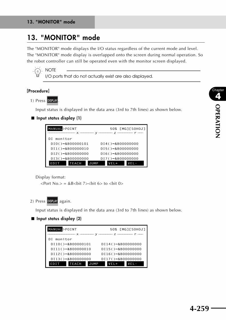
4-259
Chapter
4
OPER
ATIO
N
13. "MONITOR" modeThe "MONITOR" mode displays the I/O status regardless of the current mode and level.
The "MONITOR" mode display is overlapped onto the screen during normal operation. So
the robot controller can still be operated even with the monitor screen displayed.
n NOTE
I/O ports that do not actually exist are also displayed.
[Procedure]
1) Press .
Input status is displayed in the data area (3rd to 7th lines) as shown below.
■ Input status display (1)
MANUAL>POINT 50% [MG][S0H0J]
DI monitor
DI0()=&B00000101 DI4()=&B00000000
DI1()=&B00000010 DI5()=&B00000000
DI2()=&B00000000 DI6()=&B00000000
DI3()=&B00000000 DI7()=&B00000000EDIT TEACH JUMP VEL+ VEL-
________________ x ________ y ________ z _________ r ___
Display format:
<Port No.> = &B<bit 7><bit 6> to <bit 0>
2) Press again.
Input status is displayed in the data area (3rd to 7th lines) as shown below.
■ Input status display (2)
MANUAL>POINT 50% [MG][S0H0J]
DI monitor
DI10()=&B00000101
DI11()=&B00000010
DI12()=&B00000000
DI13()=&B00000000
DI14()=&B00000000
DI15()=&B00000000
DI16()=&B00000000
DI17()=&B00000000EDIT TEACH JUMP VEL+ VEL-
________________ x ________ y ________ z _________ r ___
13. "MONITOR" mode

4-260
Chapter
4
OPER
ATIO
N
4-261
13. "MONITOR" mode
3) Press again to display other monitor screens.
Pressing shifts the monitor screen in the following sequence.
DI monitor → DO monitor → MO monitor → LO/TO monitor → SI monitor →
SO monitor → SIW monitor → SOW monitor → Variable monitor → Task monitor →
Current monitor → Normal screen display
4) To view the previous screen, press + .
Pressing + changes the screen in the reverse of the sequence shown in 3).
n NOTE
The screen display is updated at periodic intervals.
5) Press to return to the normal screen display.
■ Example of bit information display
MANUAL>POINT 50% [MG][S0H0J]
DI monitor
DI0()=&B00000101
DI1()=&B00000001
DI2()=&B00000000
DI3()=&B00000000
DI4()=&B00000000
DI5()=&B00000000
DI6()=&B00000000
DI7()=&B00000000EDIT TEACH JUMP VEL+ VEL-
________________ x ________ y ________ z _________ r ___
The information is displayed with the following format:
<Port No.> = &B <7th bit> <6th bit> to <0th bit>
■ Example of word information display
MANUAL>POINT 50% [MG][S0H0J]
SIW monitor
SIW(0)=&H0000
SIW(1)=&H0000
SIW(2)=&H0000
SIW(3)=&H0000
SIW(4)=&H0000
SIW(5)=&H0000
SIW(6)=&H0000
SIW(7)=&H0000EDIT TEACH JUMP VEL+ VEL-
________________ x ________ y ________ z _________ r ___
The information is displayed with the following format:
<Register No.> = &H<hexadecimal>
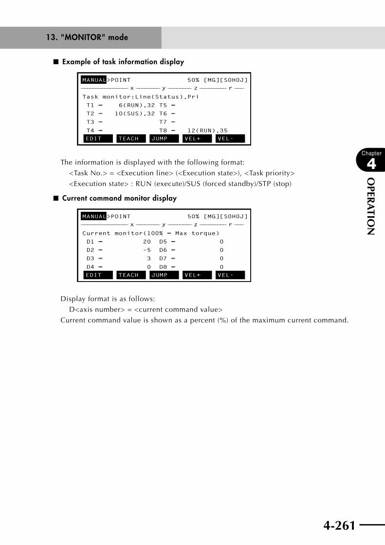
4-260 4-261
Chapter
4
OPER
ATIO
N
■ Example of task information display
MANUAL>POINT 50% [MG][S0H0J]
Task monitor:Line(Status),Pri
T1 = 6(RUN),32 T5 =
T2 = 10(SUS),32 T6 =
T3 = T7 =
T4 = T8 = 12(RUN),35EDIT TEACH JUMP VEL+ VEL-
________________ x ________ y ________ z _________ r ___
The information is displayed with the following format:
<Task No.> = <Execution line> (<Execution state>), <Task priority>
<Execution state> : RUN (execute)/SUS (forced standby)/STP (stop)
■ Current command monitor display
MANUAL>POINT 50% [MG][S0H0J]
Current monitor(100% = Max torque)
D1 = 20 D5 = 0
D2 = –5 D6 = 0
D3 = 3 D7 = 0
D4 = 0 D8 = 0EDIT TEACH JUMP VEL+ VEL-
________________ x ________ y ________ z _________ r ___
Display format is as follows:
D<axis number> = <current command value>
Current command value is shown as a percent (%) of the maximum current command.
13. "MONITOR" mode
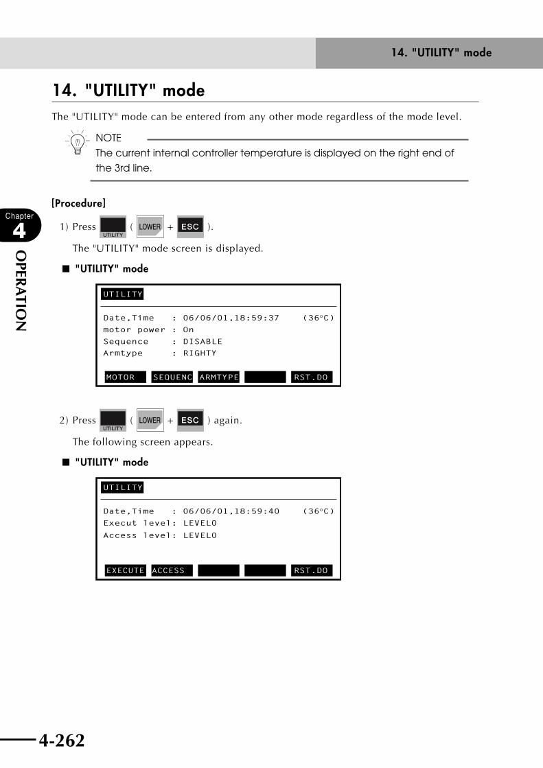
4-262
Chapter
4
OPER
ATIO
N
4-263
14. "UTILITY" mode
14. "UTILITY" modeThe "UTILITY" mode can be entered from any other mode regardless of the mode level.
n NOTE
The current internal controller temperature is displayed on the right end of
the 3rd line.
[Procedure]
1) Press ( + ).
The "UTILITY" mode screen is displayed.
■ "UTILITY" mode
UTILITY
Date,Time : 06/06/01,18:59:37 (36°C)motor power : On
Sequence : DISABLE
Armtype
: RIGHTY
MOTOR SEQUENC ARMTYPE RST.DO
2) Press ( + ) again.
The following screen appears.
■ "UTILITY" mode
UTILITY
Date,Time : 06/06/01,18:59:40 (36°C)Execut level: LEVEL0
Access level: LEVEL0
EXECUTE ACCESS RST.DO
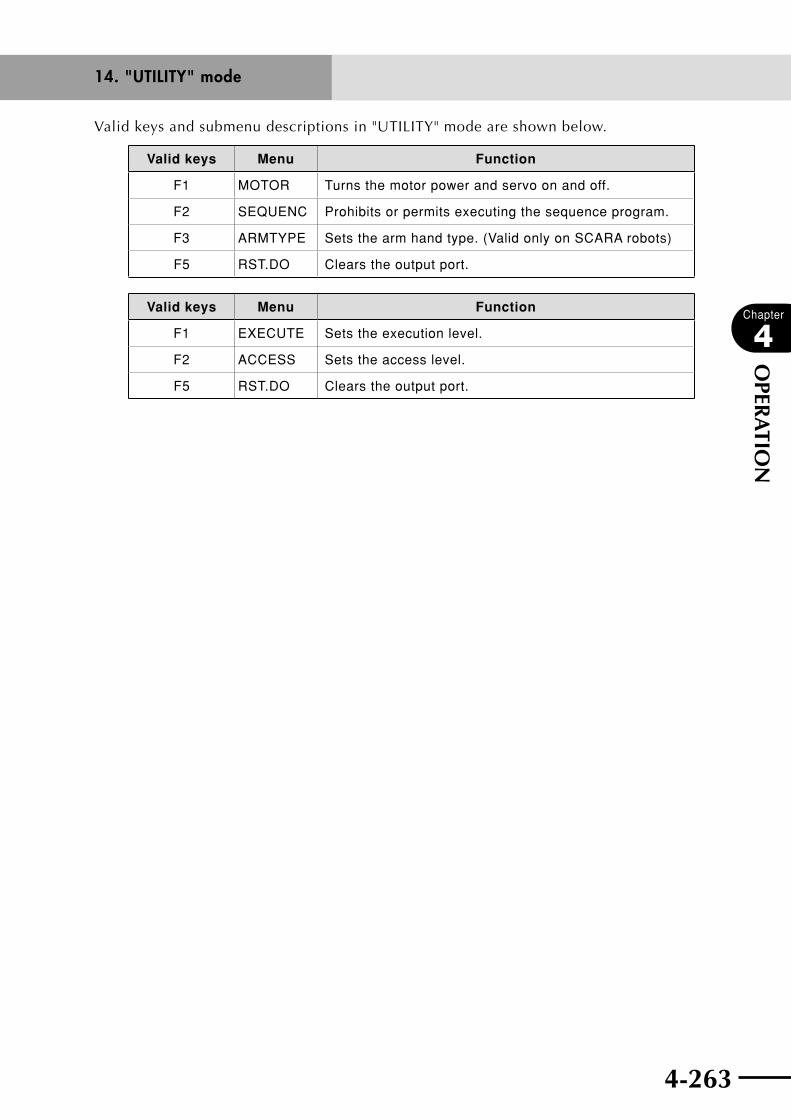
4-262 4-263
Chapter
4
OPER
ATIO
N
Valid keys and submenu descriptions in "UTILITY" mode are shown below.
Valid keys Menu Function
F1 MOTOR Turns the motor power and servo on and off.
F2 SEQUENC Prohibits or permits executing the sequence program.
F3 ARMTYPE Sets the arm hand type. (Valid only on SCARA robots)
F5 RST.DO Clears the output port.
Valid keys Menu Function
F1 EXECUTE Sets the execution level.
F2 ACCESS Sets the access level.
F5 RST.DO Clears the output port.
14. "UTILITY" mode
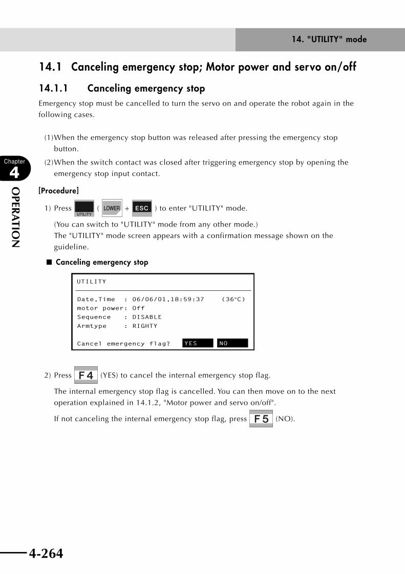
4-264
Chapter
4
OPER
ATIO
N
4-265
14. "UTILITY" mode
14.1 Canceling emergency stop; Motor power and servo on/off
14.1.1 Canceling emergency stopEmergency stop must be cancelled to turn the servo on and operate the robot again in the
following cases.
(1) When the emergency stop button was released after pressing the emergency stop
button.
(2) When the switch contact was closed after triggering emergency stop by opening the
emergency stop input contact.
[Procedure]
1) Press ( + ) to enter "UTILITY" mode.
(You can switch to "UTILITY" mode from any other mode.)
The "UTILITY" mode screen appears with a confirmation message shown on the
guideline.
■ Canceling emergency stop
UTILITY
Date,Time : 06/06/01,18:59:37 (36°C)motor power: Off
Sequence : DISABLE
Armtype : RIGHTY
Cancel emergency flag? YES NO
2) Press (YES) to cancel the internal emergency stop flag.
The internal emergency stop flag is cancelled. You can then move on to the next
operation explained in 14.1.2, "Motor power and servo on/off".
If not canceling the internal emergency stop flag, press (NO).

4-264 4-265
Chapter
4
OPER
ATIO
N
14.1.2 Motor power and servo on/offThis is usually used with the motor power turned on.
This operation is performed after emergency stop has been cancelled or when turning the
servo on/off temporarily in order to perform direct teaching.
n NOTE
When using a PHASER series robot, noise is emitted for 0.5 to 2 seconds
during the first servo-on after turning the power on. This is just the routine
pre-action for obtaining information needed to control the robot and is not
a problem.
cCAUTION
At axes with brakes, the brake can be released by pressing (Free)
( in controller versions prior to Ver. 9.13). Use particular care with
regard to heavy up/down vertical axes, as they may drop when the brake is released.
[Procedure]
1) Press (MOTOR) in "UTILITY" mode.
2) Press (On) to turn on the motor power supply and servo.
Press (Off) to turn off the motor power supply and servo.
Press (Power) to turn on the motor power supply only.
■ Servo on/off
UTILITY>MOTOR
motor power: Off
D1=M1: Brake D5=M5: no axis
D2=M2: Brake D6=M6: no axisno axis
no axisD3=M3:
D4=M4: On Off
3) Press to return to the mode selected just previous to "UTILITY" mode.
14. "UTILITY" mode

4-266
Chapter
4
OPER
ATIO
N
4-267
14. "UTILITY" mode
4) To set the servo of each axis to "On", "Off" or "Free", select the axis with the cursor
(↑/↓) keys.
When setting the servo to "On", the servo power for the axis must be turned on
beforehand by the operation in step 2.
■ Setting the servo of each axis
UTILITY>MOTOR
D3=M3 :no axisD2=M2 :Servo D6=M6 :no axisD1=M1 :Free D5=M5 :no axis
motor power : On
Servo BrakeD4=M4 :no axis
5) Set the servo status with (Servo), (Brake) or (Free).
n NOTE
In controller versions prior to Ver. 9.13, (Free) is used to free an axis
(release brake).
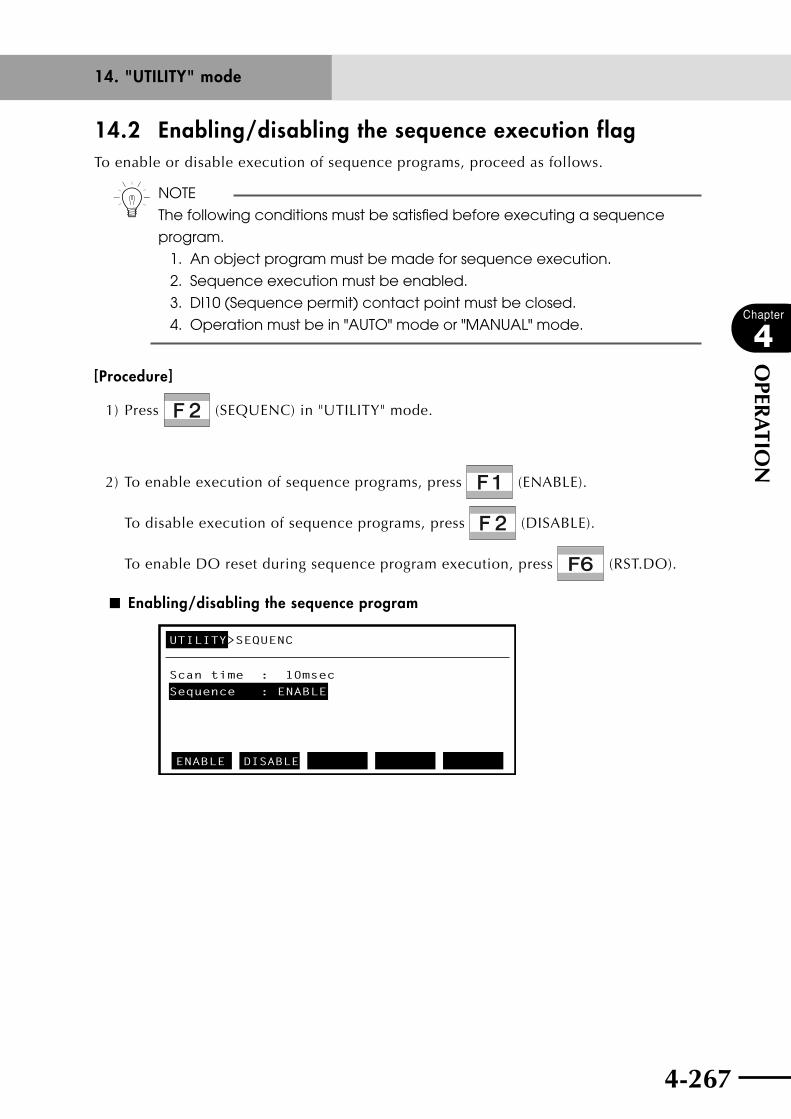
4-266 4-267
Chapter
4
OPER
ATIO
N
14.2 Enabling/disabling the sequence execution flagTo enable or disable execution of sequence programs, proceed as follows.
n NOTE
The following conditions must be satisfied before executing a sequence
program.
1. An object program must be made for sequence execution.
2. Sequence execution must be enabled.
3. DI10 (Sequence permit) contact point must be closed.
4. Operation must be in "AUTO" mode or "MANUAL" mode.
[Procedure]
1) Press (SEQUENC) in "UTILITY" mode.
2) To enable execution of sequence programs, press (ENABLE).
To disable execution of sequence programs, press (DISABLE).
To enable DO reset during sequence program execution, press (RST.DO).
■ Enabling/disabling the sequence program
UTILITY>SEQUENC
Scan time : 10msecSequence : ENABLE
ENABLE DISABLE
14. "UTILITY" mode
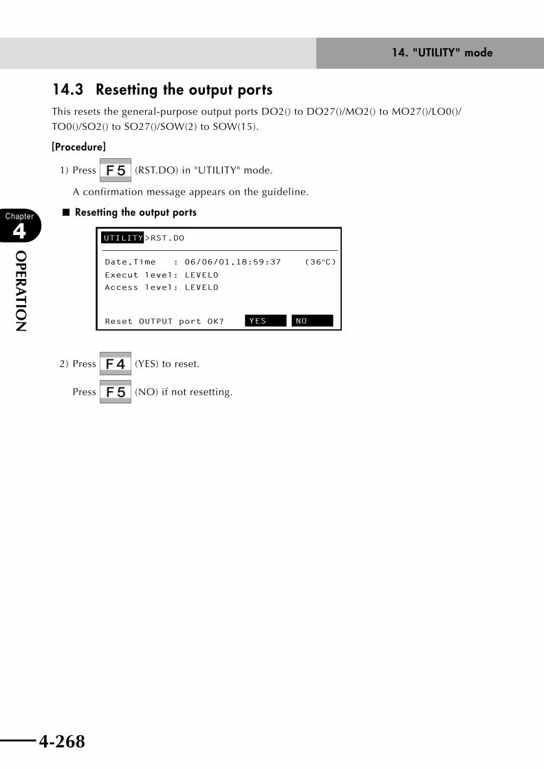
4-268
Chapter
4
OPER
ATIO
N
4-269
14. "UTILITY" mode
14.3 Resetting the output ports This resets the general-purpose output ports DO2() to DO27()/MO2() to MO27()/LO0()/
TO0()/SO2() to SO27()/SOW(2) to SOW(15).
[Procedure]
1) Press (RST.DO) in "UTILITY" mode.
A confirmation message appears on the guideline.
■ Resetting the output ports
UTILITY>RST.DO
Date,Time : 06/06/01,18:59:37 (36°C)
Reset OUTPUT port OK? YES NO
Execut level: LEVEL0
Access level: LEVEL0
2) Press (YES) to reset.
Press (NO) if not resetting.

4-268 4-269
Chapter
4
OPER
ATIO
N
14.4 Changing the execution levelProgram execution levels can be set as shown in the table below. However, the following
commands are usable only when return-to-origin is complete.
Movement commands : MOVE, MOVE2, MOVEI, MOVEI2, DRIVE, DRIVE2,
DRIVEI, DRIVEI2, PMOVE, PMOVE2, PATH START
Position acquisition command : WHERE, WHERE2, WHRXY, WHRXY2
n NOTE
Execution level is automatically set to "LEVEL 0" in the following cases.
1. When parameter data was damaged.
2. When system generation data was damaged.
Level
Description
Program execution at origin incomplete
When power is turned onProgram reset at program start
Return-to-origin signal in AUTO mode
Mode Program reset
LEVEL0 Disabled MANUAL mode NO NO Invalid
LEVEL1 Enabled MANUAL mode NO NO Invalid
LEVEL2 Enabled MANUAL mode YES NO Invalid
LEVEL3 Enabled AUTO mode NO NO Invalid
LEVEL4 Enabled AUTO mode YES NO Invalid
LEVEL5 Enabled MANUAL mode YES YES Invalid
LEVEL6 Enabled AUTO mode YES YES Invalid
LEVEL7 Enabled AUTO mode NO NO Valid (Note 1)
LEVEL8 Enabled AUTO mode YES YES Valid (Note 1)
Note 1: When the return-to-origin signal input (DI17) is valid in "AUTO" mode, the robot program-in-progress signal (DO13) turns on during processing by the return-to-origin signal input (DI17) in "AUTO" mode.
14. "UTILITY" mode

4-270
Chapter
4
OPER
ATIO
N
4-271
14. "UTILITY" mode
14.4.1 Changing the execution levelTo change the execution level, proceed as follows.
[Procedure]
1) Press ( + ) twice to enter "UTILITY" mode, then press
(EXECUTE).
■ Changing the execution level (1)
UTILITY
Date,Time : 06/06/01,12:36:37 (36°C)Execut level: LEVEL7
Access level: LEVEL0
EXECUTE ACCESS RST.DO
2) Select the execution level with (LEVEL0) to (LEVEL8).
■ Changing the execution level (2)
UTILITY>EXECUTE
Execut level: LEVEL7
LEVEL0 LEVEL1 LEVEL2 LEVEL3 LEVEL4
3) Press to exit "UTILITY" mode.
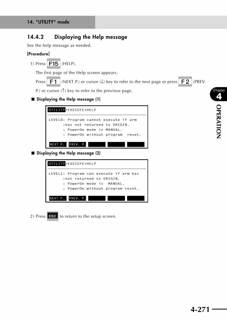
4-270 4-271
Chapter
4
OPER
ATIO
N
14.4.2 Displaying the Help messageSee the help message as needed.
[Procedure]
1) Press (HELP).
The first page of the Help screen appears.
Press (NEXT P.) or cursor (↓) key to refer to the next page or press (PREV.
P.) or cursor (↑) key to refer to the previous page.
■ Displaying the Help message (1)
UTILITY>EXECUTE>HELP
LEVEL0: Program cannot execute if arm
:has not returned to ORIGIN.
: PowerOn mode is MANUAL.
: PowerOn without program reset.
NEXT P. PREV. P.
■ Displaying the Help message (2)
UTILITY>EXECUTE>HELP
LEVEL1: Program can execute if arm has
:not returned to ORIGIN.
: PowerOn mode is MANUAL.
: PowerOn without program reset.
NEXT P. PREV. P.
2) Press to return to the setup screen.
14. "UTILITY" mode

4-272
Chapter
4
OPER
ATIO
N
4-273
14. "UTILITY" mode
14.5 Changing the access level (operation level)Once the robot system is installed, anyone can change its program and point data.
However, unauthorized changing of such data can be a source of trouble.
To prevent such problems, the robot controller can be set to operating levels that permit
or prohibit changing program and point data.
The operation level can be set to any of the following levels.
n NOTE
Access level is automatically set to "LEVEL 0" in the following cases.
1. When "ALL" was executed during memory initialization setting (Refer to
"12.4.2 Initializing the memory".)
2. When the memory was destroyed (when "9.3: Memory destroyed"
message was displayed)
3. When a program was destroyed (when"9.1: Program destroyed" message
was displayed)
4. When point data was destroyed (when "9.2: Point data destroyed"
message was displayed)
5. When shift data was destroyed (when "9.6: Shift data destroyed" message
was displayed)
6. When hand data was destroyed (when "9.7: Hand data destroyed"
message was displayed)
7. When a parameter was destroyed (when "9.4: Parameter destroyed"
message was displayed)
8. When generation data was destroyed (when "9.33: Sys. generation
destroyed" message was displayed)
Level Description
LEVEL0 All operations are allowed.
LEVEL1 All data changes are prohibited. (Program changes, teaching, data deletion, data initializing, etc are prohibited.)
LEVEL2 In addition to level 1, mode selection is restricted to MANUAL and AUTO modes.
LEVEL3 In addition to level 2, mode speed changes and display of program list in AUTO mode are prohibited.
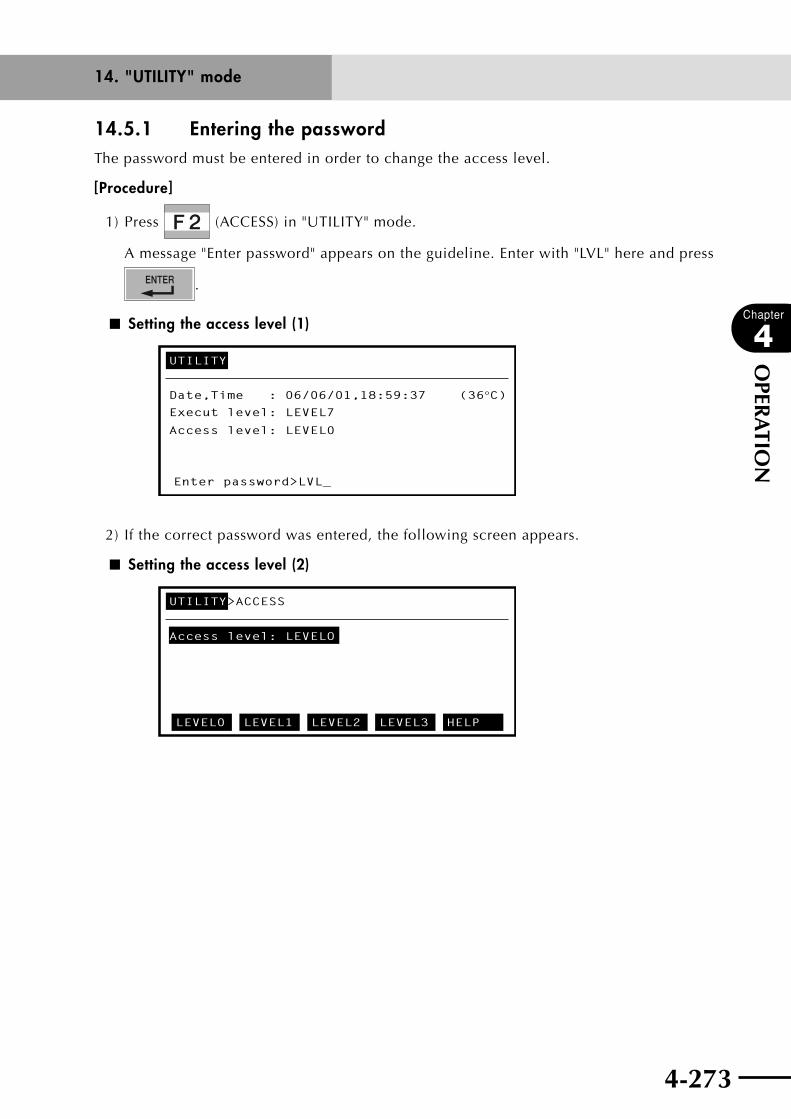
4-272 4-273
Chapter
4
OPER
ATIO
N
14.5.1 Entering the passwordThe password must be entered in order to change the access level.
[Procedure]
1) Press (ACCESS) in "UTILITY" mode.
A message "Enter password" appears on the guideline. Enter with "LVL" here and press
.
■ Setting the access level (1)
UTILITY
Date,Time : 06/06/01,18:59:37 (36°C)Execut level: LEVEL7
Access level: LEVEL0
Enter password>LVL_
2) If the correct password was entered, the following screen appears.
■ Setting the access level (2)
UTILITY>ACCESS
Access level: LEVELO
LEVEL0 LEVEL1 LEVEL2 LEVEL3 HELP
14. "UTILITY" mode

4-274
Chapter
4
OPER
ATIO
N
4-275
14. "UTILITY" mode
14.5.2 Changing the access levelChange the access level as needed.
[Procedure]
1) Set the access level with (LEVEL0) to (LEVEL3).
■ Setting the access level (3)
UTILITY>ACCESS
Access level: LEVEL2
LEVEL0 LEVEL1 LEVEL2 LEVEL3 HELP

4-274 4-275
Chapter
4
OPER
ATIO
N
14.5.3 Displaying the Help messageSee the help message as needed.
[Procedure]
1) Press (HELP).
The first page of the Help screen appears.
Press (NEXT P.) or cursor (↓) key to refer to the next page or press (PREV.
P.) or cursor (↑) key to refer to the previous page.
■ Access level Help screen (first page)
UTILITY>ACCESS>HELP
LEVEL0:All data access available
LEVEL1:Data change invalid
NEXT P. PREV. P.
■ Access level Help screen (second page)
UTILITY>>ACCESS>HELP
LEVEL2:LEVEL1 + SYSTEM & PROGRAM mode
change invalid
LEVEL3:LEVEL2 + Program list display &
speed change invalid
NEXT P. PREV. P.
14. "UTILITY" mode

4-276
MEMO
Chapter 5 PARALLEL I/O INTERFACE
Contents
1. Standard I/O interface overview 5-11.1 ID setting 5-2
1.2 Connector I/O signals 5-3
1.3 Connector pin numbers 5-6
1.4 Connecting the power supply 5-71.4.1 NPN/PNP power connector wiring 5-8
1.5 Typical input signal connection 5-9
1.6 Typical output signal connection 5-10
1.7 Dedicated I/O signals 5-111.7.1 Dedicated input signals 5-11
1.7.2 Dedicated output signals 5-13
1.8 General-purpose I/O signals 5-151.8.1 General-purpose output reset 5-15
1.9 Dedicated I/O signal timing charts 5-161.9.1 Turning the power on 5-16
1.9.2 Emergency stop and servo ON 5-18
1.9.3 Return-to-origin 5-19
1.9.4 Mode switching 5-20
1.9.5 Automatic operation 5-21
2. Ratings 5-22
3. Precautions 5-23

5-1
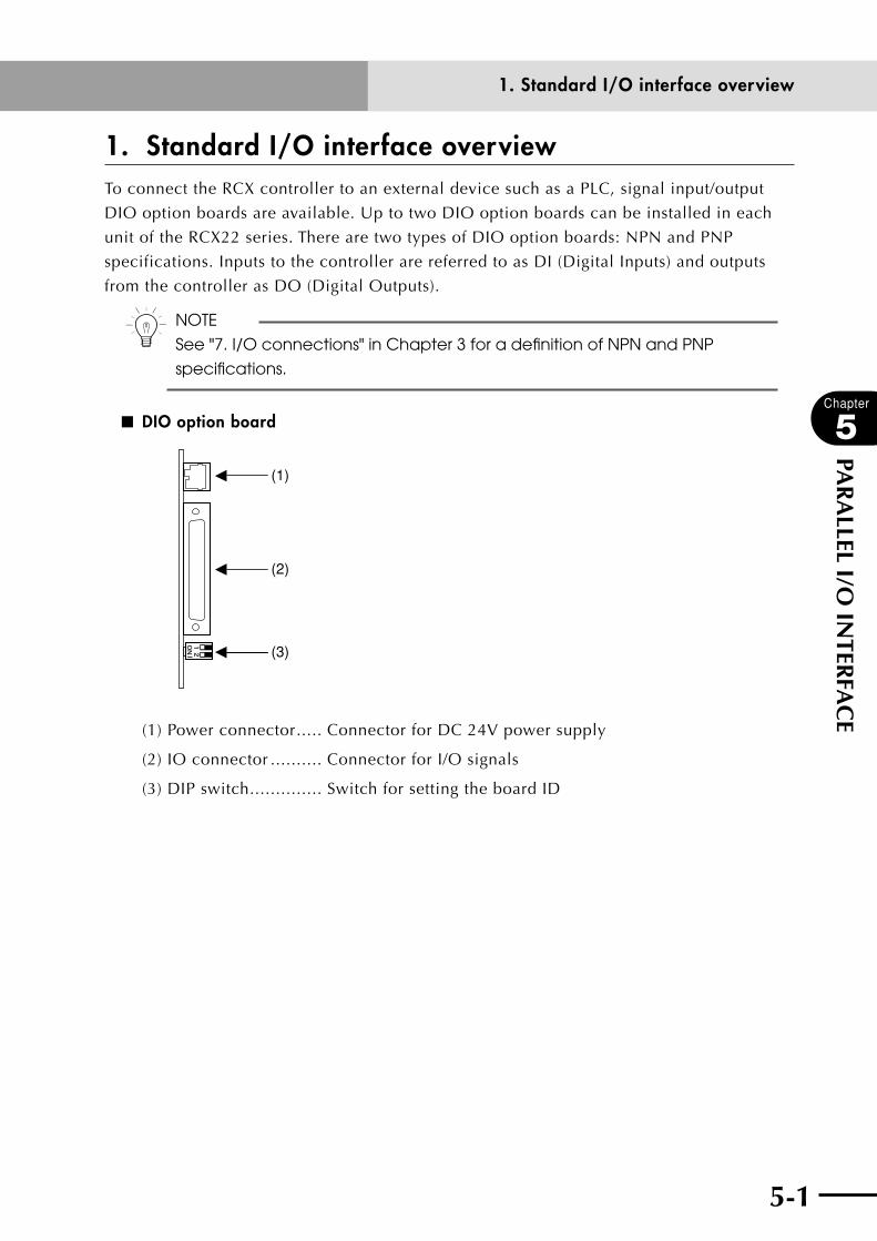
5-1
Chapter
5
PAR
ALLEL I/O
INTER
FAC
E
1. Standard I/O interface overviewTo connect the RCX controller to an external device such as a PLC, signal input/output
DIO option boards are available. Up to two DIO option boards can be installed in each
unit of the RCX22 series. There are two types of DIO option boards: NPN and PNP
specifications. Inputs to the controller are referred to as DI (Digital Inputs) and outputs
from the controller as DO (Digital Outputs).
n NOTE
See "7. I/O connections" in Chapter 3 for a definition of NPN and PNP
specifications.
■ DIO option board
(1)
(2)
(3)
(1) Power connector ..... Connector for DC 24V power supply
(2) IO connector .......... Connector for I/O signals
(3) DIP switch .............. Switch for setting the board ID
1. Standard I/O interface overview
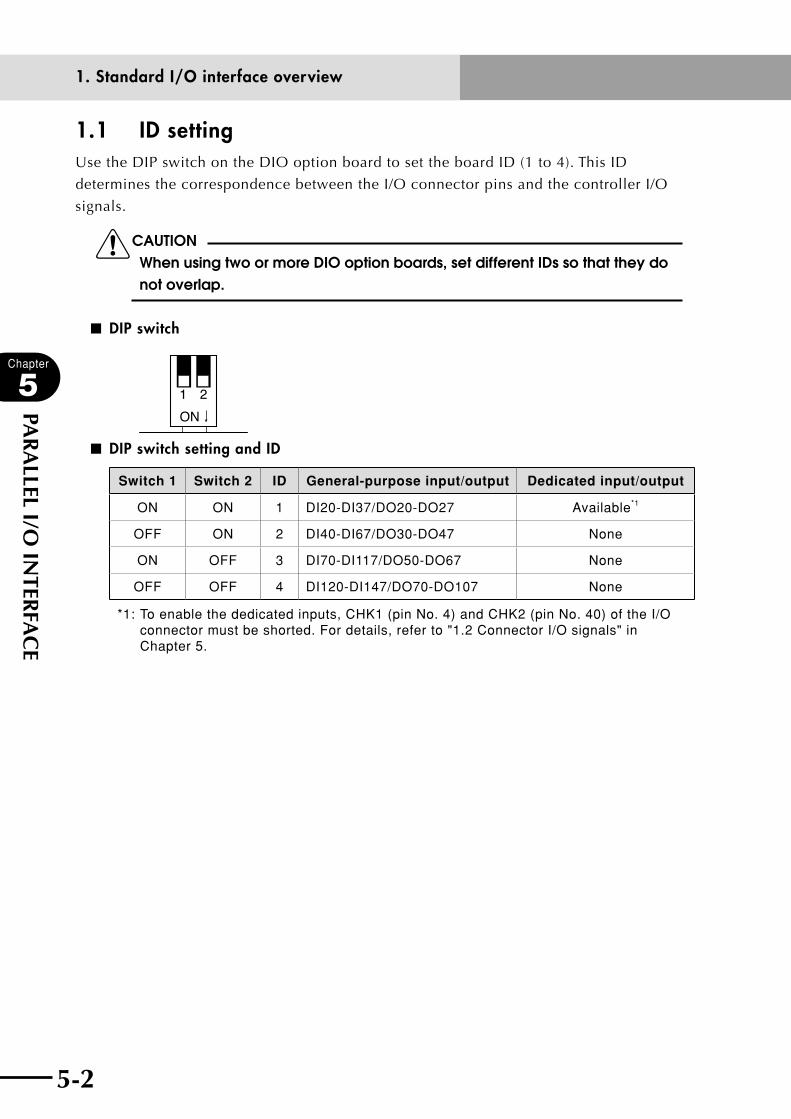
5-2
Chapter
5
PAR
ALLEL I/O
INTER
FAC
E
5-3
1.1 ID settingUse the DIP switch on the DIO option board to set the board ID (1 to 4). This ID
determines the correspondence between the I/O connector pins and the controller I/O
signals.
cCAUTIONWhen using two or more DIO option boards, set different IDs so that they do not overlap.
■ DIP switch
■ DIP switch setting and ID
Switch 1 Switch 2 ID General-purpose input/output Dedicated input/output
ON ON 1 DI20-DI37/DO20-DO27 Available*1
OFF ON 2 DI40-DI67/DO30-DO47 None
ON OFF 3 DI70-DI117/DO50-DO67 None
OFF OFF 4 DI120-DI147/DO70-DO107 None
*1: To enable the dedicated inputs, CHK1 (pin No. 4) and CHK2 (pin No. 40) of the I/O connector must be shorted. For details, refer to "1.2 Connector I/O signals" in Chapter 5.
1. Standard I/O interface overview
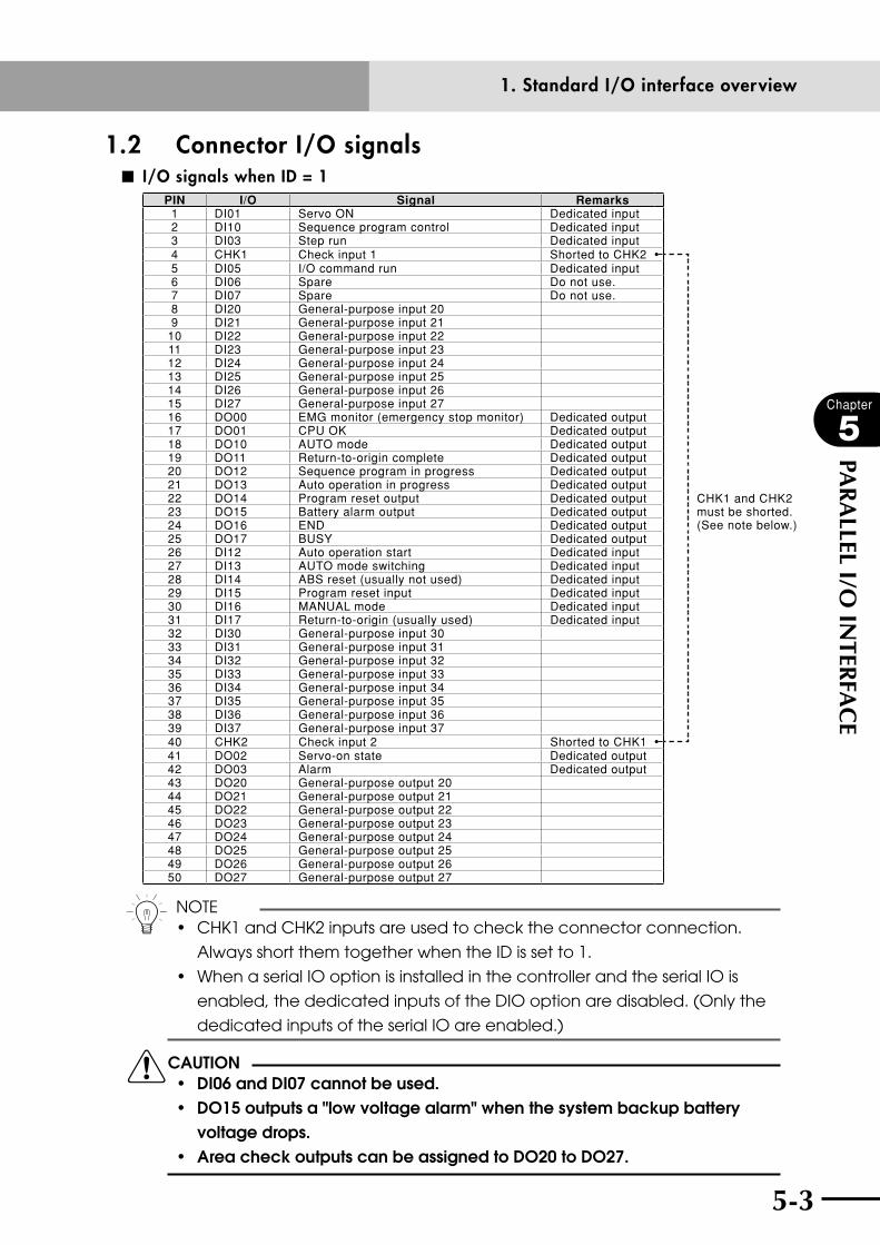
5-2 5-3
Chapter
5
PAR
ALLEL I/O
INTER
FAC
E
1.2 Connector I/O signals■ I/O signals when ID = 1
PIN I/O Signal Remarks1 DI01 Servo ON Dedicated input2 DI10 Sequence program control Dedicated input3 DI03 Step run Dedicated input4 CHK1 Check input 1 Shorted to CHK25 DI05 I/O command run Dedicated input6 DI06 Spare Do not use.7 DI07 Spare Do not use.8 DI20 General-purpose input 209 DI21 General-purpose input 21
10 DI22 General-purpose input 2211 DI23 General-purpose input 2312 DI24 General-purpose input 2413 DI25 General-purpose input 2514 DI26 General-purpose input 2615 DI27 General-purpose input 2716 DO00 EMG monitor (emergency stop monitor) Dedicated output17 DO01 CPU OK Dedicated output18 DO10 AUTO mode Dedicated output19 DO11 Return-to-origin complete Dedicated output20 DO12 Sequence program in progress Dedicated output21 DO13 Auto operation in progress Dedicated output22 DO14 Program reset output Dedicated output CHK1 and CHK2
must be shorted. (See note below.)
23 DO15 Battery alarm output Dedicated output24 DO16 END Dedicated output25 DO17 BUSY Dedicated output26 DI12 Auto operation start Dedicated input27 DI13 AUTO mode switching Dedicated input28 DI14 ABS reset (usually not used) Dedicated input29 DI15 Program reset input Dedicated input30 DI16 MANUAL mode Dedicated input31 DI17 Return-to-origin (usually used) Dedicated input32 DI30 General-purpose input 3033 DI31 General-purpose input 3134 DI32 General-purpose input 3235 DI33 General-purpose input 3336 DI34 General-purpose input 3437 DI35 General-purpose input 3538 DI36 General-purpose input 3639 DI37 General-purpose input 3740 CHK2 Check input 2 Shorted to CHK141 DO02 Servo-on state Dedicated output42 DO03 Alarm Dedicated output43 DO20 General-purpose output 2044 DO21 General-purpose output 2145 DO22 General-purpose output 2246 DO23 General-purpose output 2347 DO24 General-purpose output 2448 DO25 General-purpose output 2549 DO26 General-purpose output 2650 DO27 General-purpose output 27
n NOTE• CHK1andCHK2inputsareusedtochecktheconnectorconnection.
Always short them together when the ID is set to 1.
• WhenaserialIOoptionisinstalledinthecontrollerandtheserialIOis
enabled, the dedicated inputs of the DIO option are disabled. (Only the
dedicated inputs of the serial IO are enabled.)
cCAUTION • di06anddi07cannotbeused.• do15outputsa"lowvoltagealarm"whenthesystembackupbattery
voltage drops.• Areacheckoutputscanbeassignedtodo20todo27.
1. Standard I/O interface overview

5-4
Chapter
5
PAR
ALLEL I/O
INTER
FAC
E
5-5
■ I/O signals when ID = 2, 3 or 4
PINID
Signal2 3 4
1 --- Spare2 DI40 DI70 DI120 General-purpose input3 --- Spare4 DI41 DI71 DI121 General-purpose input5 --- Spare6 --- Spare7 --- Spare8 DI50 DI100 DI130 General-purpose input9 DI51 DI101 DI131 General-purpose input
10 DI52 DI102 DI132 General-purpose input11 DI53 DI103 DI133 General-purpose input12 DI54 DI104 DI134 General-purpose input13 DI55 DI105 DI135 General-purpose input14 DI56 DI106 DI136 General-purpose input15 DI57 DI107 DI137 General-purpose input16 --- Spare17 --- Spare18 DO30 DO50 DO70 General-purpose output19 DO31 DO51 DO71 General-purpose output20 DO32 DO52 DO72 General-purpose output21 DO33 DO53 DO73 General-purpose output22 DO34 DO54 DO74 General-purpose output23 DO35 DO55 DO75 General-purpose output24 DO36 DO56 DO76 General-purpose output25 DO37 DO57 DO77 General-purpose output26 DI42 DI72 DI122 General-purpose input27 DI43 DI73 DI123 General-purpose input28 DI44 DI74 DI124 General-purpose input29 DI45 DI75 DI125 General-purpose input30 DI46 DI76 DI126 General-purpose input31 DI47 DI77 DI127 General-purpose input32 DI60 DI110 DI140 General-purpose input33 DI61 DI111 DI141 General-purpose input34 DI62 DI112 DI142 General-purpose input35 DI63 DI113 DI143 General-purpose input36 DI64 DI114 DI144 General-purpose input37 DI65 DI115 DI145 General-purpose input38 DI66 DI116 DI146 General-purpose input39 DI67 DI117 DI147 General-purpose input40 --- Spare41 --- Spare42 --- Spare43 DO40 DO60 DO100 General-purpose output44 DO41 DO61 DO101 General-purpose output45 DO42 DO62 DO102 General-purpose output46 DO43 DO63 DO103 General-purpose output47 DO44 DO64 DO104 General-purpose output48 DO45 DO65 DO105 General-purpose output49 DO46 DO66 DO106 General-purpose output50 DO47 DO67 DO107 General-purpose output
cCAUTION• oncontrollersofver.9.22onwards,theareacheckcanbeassignedto DO20 to DO27, DO30 to DO37, DO40 to DO47, DO50 to DO57, DO60 to DO67, DO70 to DO77, and DO100 to DO107. • donotconnectanythingtothe"spare"pins.
1. Standard I/O interface overview

5-4 5-5
Chapter
5
PAR
ALLEL I/O
INTER
FAC
E
■ Pinout tables
STD.IO
1 DI01 Servo ON 26 DI12 RUN2 DI10 SEQ control 27 DI13 AUTO
3 DI03 STEP-R 28 DI14 ABS (absolute) reset
4 CHK1 Check input 1 29 DI15 RESET5 DI05 IO command 30 DI16 MANUAL
6 DI06 (Spare) 31 DI17 ORIGIN7 DI07 (Spare) 32 DI30 General-purpose
input8 DI20 General-purpose
input 33 DI31 General-purpose input9 DI21 General-purpose
input 34 DI32 General-purpose input
10 DI22 General-purpose input 35 DI33 General-purpose
input11 DI23 General-purpose input 36 DI34 General-purpose
input12 DI24 General-purpose
input 37 DI35 General-purpose input13 DI25 General-purpose
input 38 DI36 General-purpose input
14 DI26 General-purpose input 39 DI37 General-purpose
input15 DI27 General-purpose input 40 CHK2 Check input 2
16 DO00 E-STOPOUT 41 DO02 SERVO17 DO01 CPUOK 42 DO03 ALARM
18 DO10 AUTO 43 DO20 General-purpose output19 DO11 ORGOK 44 DO21 General-purpose
output20 DO12 SEQRUN 45 DO22 General-purpose
output21 DO13 RUN 46 DO23 General-purpose output
22 DO14 RESET 47 DO24 General-purpose output23 DO15 BATALM 48 DO25 General-purpose
output24 DO16 END 49 DO26 General-purpose
output25 DO17 BUSY 50 DO27 General-purpose output
OP.DIO
1 − Do not use. 26 DI42 General-purpose input
2 DI40 General-purpose input 27 DI43 General-purpose
input3 − Do not use. 28 DI44 General-purpose input
4 DI41 General-purpose input 29 DI45 General-purpose
input5 − Do not use. 30 DI46 General-purpose input
6 − Do not use. 31 DI47 General-purpose input7 − Do not use. 32 DI60 General-purpose
input8 DI50 General-purpose
input 33 DI61 General-purpose input9 DI51 General-purpose
input 34 DI62 General-purpose input
10 DI52 General-purpose input 35 DI63 General-purpose
input11 DI53 General-purpose input 36 DI64 General-purpose
input12 DI54 General-purpose
input 37 DI65 General-purpose input13 DI55 General-purpose
input 38 DI66 General-purpose input
14 DI56 General-purpose input 39 DI67 General-purpose
input15 DI57 General-purpose input 40 − Do not use.
16 − Do not use. 41 − Do not use.17 − Do not use. 42 − Do not use.
18 DO30 General-purpose output 43 DO40 General-purpose
output19 DO31 General-purpose output 44 DO41 General-purpose
output20 DO32 General-purpose
output 45 DO42 General-purpose output
21 DO33 General-purpose output 46 DO43 General-purpose
output22 DO34 General-purpose output 47 DO44 General-purpose
output23 DO35 General-purpose
output 48 DO45 General-purpose output24 DO36 General-purpose
output 49 DO46 General-purpose output
25 DO37 General-purpose output 50 DO47 General-purpose
output
1. Standard I/O interface overview

5-6
Chapter
5
PAR
ALLEL I/O
INTER
FAC
E
5-7
1.3 Connector pin numbers■ Cable connector pin numbers as viewed from solder side
26
28
30
32
34
36
38
40
42
44
46
48
50
27
29
31
33
35
37
39
41
43
45
47
4924
22
20
18
16
14
10
8
6
4
21
3
5
7
9
1112
13
15
17
19
21
23
25
12
34
56
78
910
1112
1314
1516
1718
1920
2122
2324
25
2627
2829
3031
3233
3435
3637
3839
4041
4243
4445
4647
4849
50
Connector shell No. 10350-52A0-008 Sumitomo 3M
Connector plug No. 10150-3000PE Sumitomo 3M
1. Standard I/O interface overview
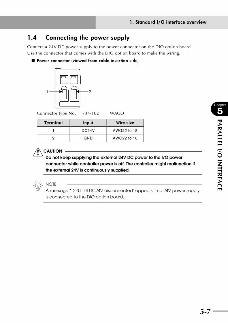
5-6 5-7
Chapter
5
PAR
ALLEL I/O
INTER
FAC
E
1.4 Connecting the power supplyConnect a 24V DC power supply to the power connector on the DIO option board.
Use the connector that comes with the DIO option board to make the wiring.
■ Power connector (viewed from cable insertion side)
21
Connector type No. 734-102 WAGO
Terminal Input Wire size
1 DC24V AWG22 to 18
2 GND AWG22 to 18
cCAUTION Do not keep supplying the external 24V DC power to the I/O power connector while controller power is off. The controller might malfunction if the external 24V is continuously supplied.
n NOTE
A message "12.31: DI DC24V disconnected" appears if no 24V power supply
is connected to the DIO option board.
1. Standard I/O interface overview
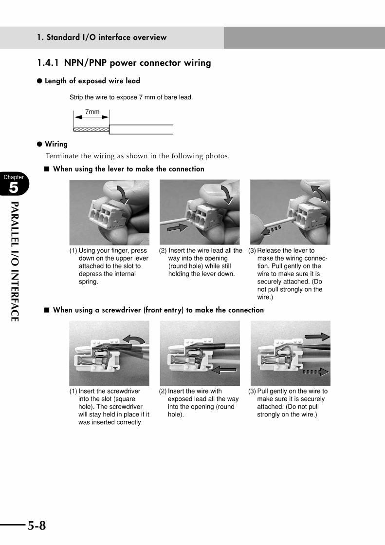
5-8
Chapter
5
PAR
ALLEL I/O
INTER
FAC
E
5-9
1.4.1 NPN/PNP power connector wiring
l Length of exposed wire lead
Strip the wire to expose 7 mm of bare lead.
7mm
l Wiring
Terminate the wiring as shown in the following photos.
■ When using the lever to make the connection
(1) Using your finger, press down on the upper lever attached to the slot to depress the internal spring.
(2) Insert the wire lead all the way into the opening (round hole) while still holding the lever down.
(3) Release the lever to make the wiring connec-tion. Pull gently on the wire to make sure it is securely attached. (Do not pull strongly on the wire.)
■ When using a screwdriver (front entry) to make the connection
(1) Insert the screwdriver into the slot (square hole). The screwdriver will stay held in place if it was inserted correctly.
(2) Insert the wire with exposed lead all the way into the opening (round hole).
(3) Pull gently on the wire to make sure it is securely attached. (Do not pull strongly on the wire.)
1. Standard I/O interface overview

5-8 5-9
Chapter
5
PAR
ALLEL I/O
INTER
FAC
E
1.5 Typical input signal connection■ NPN specifications
DC24V
DI
DI
GND
■ PNP specifications
DC24V
DI
DI
GND
1. Standard I/O interface overview
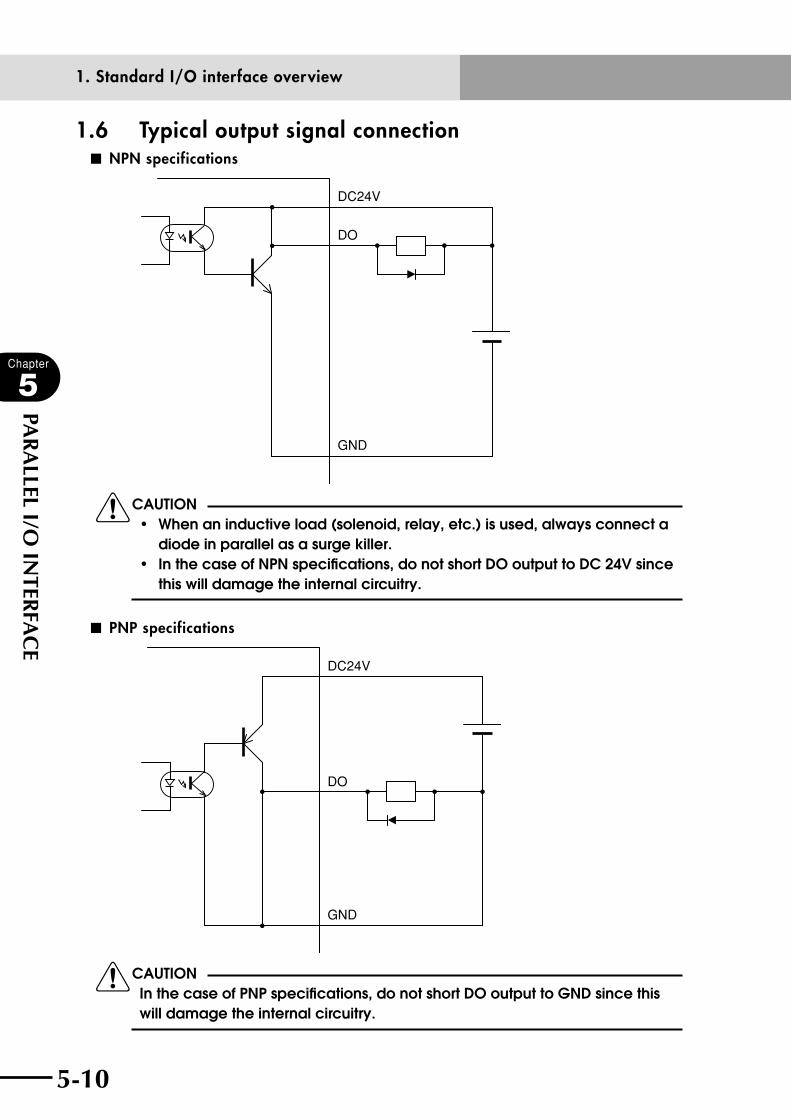
5-10
Chapter
5
PAR
ALLEL I/O
INTER
FAC
E
5-11
1.6 Typical output signal connection ■ NPN specifications
DC24V
DO
GND
cCAUTION• whenaninductiveload(solenoid,relay,etc.)isused,alwaysconnecta
diode in parallel as a surge killer. • inthecaseofnpnspecifications,donotshortdooutputtodc24vsince
this will damage the internal circuitry.
■ PNP specifications
DC24V
DO
GND
cCAUTIONIn the case of PNP specifications, do not short DO output to GND since this will damage the internal circuitry.
1. Standard I/O interface overview

5-10 5-11
Chapter
5
PAR
ALLEL I/O
INTER
FAC
E
1.7 Dedicated I/O signalsThese signals are used to control the robot controller from an external device.
1.7.1 Dedicated input signalsThese input signals are used to control the robot controller from an external device. The
input status can be checked from the robot program or sequence program.
n NOTE
The pulse width of an input signal must be longer than 10ms. If two or more
dedicated input signals are supplied simultaneously, those signals may not
be recognized by the controller. Provide an interval of at least 100ms
between each dedicated input signal.
DI01 Servo ON
Cancels emergency stop and turns on the robot servo.
At the rising edge of this signal, DO03 (Alarm output) is cleared, the robot servo
turns on, and DO02 (Servo-on state output) turns on. At this point, the main power
must have been input and DI00 (Emergency stop ready signal) must be on.
n NOTE
When using a PHASER series robot, noise is emitted for 0.5 to 2 seconds
during the first servo-on after turning the power on. This is just the routine
pre-action for obtaining information needed to control the robot and is not
a problem.
DI03 Step run
Executes a step of the program in "AUTO" mode.
At the rising edge of this signal, one line of the program is executed. DO13 (Auto
operation-in-progress output) turns on during operation. Step operation cannot be
performed during emergency stop or when DI11 (Interlock input) is off.
n NOTE
The DI00 (Emergency stop ready signal) and DI11 (Interlock input) input
terminals are on the SAFETY connector. Refer to Chapter 6 for detailed
information.
DI05 IO command run
Executes an IO command.
At the rising edge of this signal, an IO command is executed. However, when the IO
command setting is set to "Disable" by using the DIO option board parameter, no IO
command is executed. DO17 (BUSY) turns on during IO command execution. DO16
(END) turns on when the IO command has ended normally.
1. Standard I/O interface overview

5-12
Chapter
5
PAR
ALLEL I/O
INTER
FAC
E
5-13
n NOTE
When not using IO commands, set the IO command setting to "Disable" by parameter. Refer to the programming manual for detailed information on IO commands.
DI10 Sequence permitAllows or prohibits the execution of a sequence program. In "AUTO" or "MANUAL" mode, a sequence program is executed while this signal is on. However, no sequence program is executed unless a sequence object (complied sequence program) exists and "Sequence" is set to "ENABLE" in "UTILITY" mode. DO12 (Sequence program-in-progress output) turns on during sequence program execution.
n NOTERefer to the programming manual for detailed information on sequence
programs.
DI12 Auto operation startStarts automatic operation of a program in "AUTO" mode. At the rising edge of this signal, automatic operation of a program starts. DO13 (Auto operation-in-progress output) turns on during automatic operation. Automatic operation cannot be performed during emergency stop or when DI11 (Interlock) input is off.
n NOTEThe DI00 (Emergency stop ready signal) and DI11 (Interlock input) input terminals are located in the SAFETY connector. See Chapter 6 for detailed information.
DI13 "AUTO" mode switchingSwitches to "AUTO" mode. At the rising edge of this signal, the controller switches to "AUTO" mode and DO10 ("AUTO" mode output) turns on.
DI14 ABS (absolute) resetPerforms absolute reset on the absolute specification axes. In MANUAL mode, at the rising edge of this signal, absolute reset is performed on each axis in the return-to-origin order specified by parameter. If no absolute specification axis exists, an error "0.11: ABS. motor disconnected" occurs. This input signal is only for the axes whose return-to-origin method uses a sensor or stroke end detection. Absolute reset cannot be performed on the axes whose return-to-origin method uses a mark even if absolute reset is incomplete on those axes.
DI15 Program reset inputResets the program in "AUTO" mode. At the rising edge of this signal, the program is reset and DO14 (Program reset output) turns on.
1. Standard I/O interface overview

5-12 5-13
Chapter
5
PAR
ALLEL I/O
INTER
FAC
E
DI16 "MANUAL" mode switchingSwitches to "MANUAL" mode. At the rising edge of this signal, the controller switches to "MANUAL" mode.
DI17 Return-to-originPerforms return-to-origin on incremental mode axes and semi-absolute mode axes.When return-to-origin is performed, incremental mode axes return to their origins. On semi-absolute mode axes, an absolute search (also called absolute reset) is performed by return-to-origin operation.In MANUAL mode, at the rising edge of this signal, each axis returns to its origin in the return-to-origin order specified by parameter. If no incremental mode axis and semi-absolute axis exist, an error "0.10: INC. motor disconnected" occurs. This input signal is only for the axes whose return-to-origin method uses a sensor or stroke end detection.
1.7.2 Dedicated output signalsThese output signals indicate the controller status. The output status can be checked from
the robot program or sequence program, but cannot be changed.
DO00 EMG monitor (emergency stop monitor)
This signal monitors DI00 (Emergency stop ready signal) status and stays on while
DI00 is off. Canceling emergency stop does not clear this signal as long as DI00 is
off.
DO01 CPU OK
This signal is on while the controller is operating normally.
This signal turns off when either of the following conditions occurs, and the
controller stops.
•Whenaseriouserrorhasoccurred
•Whenthecontrolpowersupplyvoltagehasdroppedbelowthespecifiedvalue
When this signal turns off, the controller power must be turned off and then back on,
in order to restore the normal state.
DO02 Servo-on state
This signal is on while the controller main power is on. The SRV indicator LED on the
front panel of the controller is lit while this signal is on.
DO03 Alarm
This signal turns on in the following cases. The ERR indicator LED on the front panel
of the controller also lights up when this alarm signal turns on.
1) When DI00 (Emergency stop ready signal) turned off. In this case, canceling
emergency stop or inputting DI01 (Servo ON) turns off the alarm.
1. Standard I/O interface overview

5-14
Chapter
5
PAR
ALLEL I/O
INTER
FAC
E
5-15
2) When a serious error was detected by the controller. In this case, canceling
emergency stop turns off the alarm, but the controller power must be turned
off and then back on, in order to turn on the servo again or perform automatic
operation.
3) When the controller stopped operation due to a serious error. The alarm cannot be
turned off in this case. The controller power must be turned off and then back on,
to turn off the alarm.
DO10 "AUTO" mode
This signal is on while the controller is in "AUTO" mode.
DO11 Return-to-origin complete
This signal is on when return-to-origin has been completed on all incremental axes
and semi-absolute axes and absolute reset has been performed on all absolute axes.
DO12 Sequence program in progress
This signal is on while a sequence program is being executed.
DO13 Auto operation in progress
This signal is on while a program is being executed in "AUTO" mode.
DO14 Program reset output
This signal turns on when the program has been reset correctly and turns off when
automatic operation or step operation starts.
DO15 Battery alarm
This signal turns on when the system backup battery voltage is low.
DO16 END
This signal turns on when the system backup battery voltage is low.
DO17 BUSY
This signal is on while an IO command is being executed.
1. Standard I/O interface overview

5-14 5-15
Chapter
5
PAR
ALLEL I/O
INTER
FAC
E
1.8 General-purpose I/O signalsThese general-purpose I/O signals are available to the user and can be connected to
external devices such as sensors, valves and PLC. The I/O status can be checked from the
robot program or sequence program. Any desired value can be output from the general-
purpose outputs.
The area check output can be assigned as follows:
•ControllerspriortoVer.9.22
DO20 to DO27
•ControllersofVer.9.22onwards
DO20 to DO27, DO30 to DO37, DO40 to DO47, DO50 to DO57, DO60 to
DO67, DO70 to DO77, DO100 to DO107
n NOTE
If the port used for area check output is the same as that used by the user
program, the output data might change. Do not use the same port.
1.8.1 General-purpose output resetAll the general-purpose output signals are reset in the following cases.
1) When (RST.DO) is selected in "UTILITY" mode.
2) When all of the following conditions a) to c) are met:
a) “DO cond. on PGM reset / RESCDO” in Other parameters is set to "RESET".
(For details, see "12.1.3 Other parameters" in Chapter 4.)
b) No sequence program is being executed or the DO reset is enabled in the sequence
execution flag setting even if a sequence program is being executed.
(For details, see "14.2 Enabling/disabling the sequence execution flag" in Chapter 4.)
c) Any of the following operations was performed.
n Compile ended successfully in "PROGRAM" mode.
n A program was compiled in "AUTO" mode and the compile ended successfully.
n (RESET) was executed in "AUTO" mode.
n The dedicated input signal DI15 (Program reset input) was turned on in "AUTO"
mode while the program was stopped.
(Refer to "1.7.1 Dedicated input signals" in this Chapter.)
n Either of the following was initialized in "SYSTEM>INIT" mode.
1. Program memory (SYSTEM>INIT>MEMORY>PROGRAM)
2. Entire memory (SYSTEM>INIT>MEMORY>ALL)
1. Standard I/O interface overview

5-16
Chapter
5
PAR
ALLEL I/O
INTER
FAC
E
5-17
■ The SWI command was executed by (DIRECT) in "AUTO" mode.
(Reset (off) does not occur if the SWI statement was executed in the program.)
■ The online commands @RESET, @INIT PGM, @INIT MEM, @INIT ALL,
or @SWI were executed.
■ The HALT statement was executed in the program.
1.9 Dedicated I/O signal timing charts
1.9.1 Turning the power on
■ Turning the power on (while emergency stop input is on)
Approx. 3 sec.
Control power
DI00(in SAFETY connector)
Emergency stop ready signal
DO00 Emergency stop contact monitor
MPRDY(in SAFETY connector)
Main power ON ready
Main power
DO01 CPU OK
DO02 Servo-on state
DO03 Alarm
•MPRDY(MainpowerONready)turnsonafterthecontrolpowersupplyturnson.
Then turn on the main power to the external device.
•AfterDO01(CPUOK)turnson,therobotservoturnsonandthenDO02(Servo-on
state) turns on. However, if serial IO setting or "SAFE" mode is enabled, the robot
starts with the servo turned off.
1. Standard I/O interface overview

5-16 5-17
Chapter
5
PAR
ALLEL I/O
INTER
FAC
E
■ Turning the power on (while emergency stop input is off)
DI00(in SAFETY connector)
DO00
MPRDY(in SAFETY connector)
DO01
DO02
DO03
Approx. 3 sec.
Control power
Emergency stop ready signal
Emergency stop contact monitor
Main power ON ready
Main power
CPU OK
Servo-on state
Alarm
•DO00(Emergencystopcontactmonitor)andDO03(Alarm)turnonafterthe
control power supply turns on. MPRDY (Main power ON ready) output remains off.
The robot starts with the servo turned off.
n NOTE
• Ittakesabout3secondsuntilCPUOKisoutputafterturningonthe
control power supply
• Themainpowersupplycanbeleftonduringoperation.
1. Standard I/O interface overview
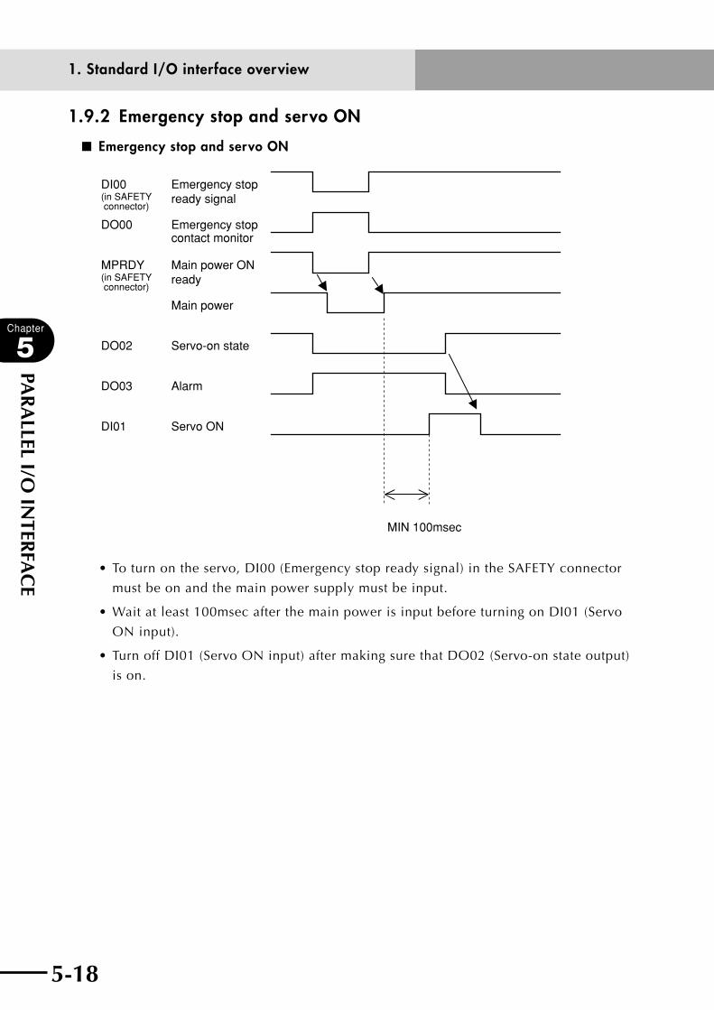
5-18
Chapter
5
PAR
ALLEL I/O
INTER
FAC
E
5-19
1.9.2 Emergency stop and servo ON
■ Emergency stop and servo ON
DI00(in SAFETY connector)
Emergency stop ready signal
DO00 Emergency stop contact monitor
MPRDY(in SAFETY connector)
Main power ON ready
Main power
DO02 Servo-on state
DO03 Alarm
DI01 Servo ON
MIN 100msec
•Toturnontheservo,DI00(Emergencystopreadysignal)intheSAFETYconnector
must be on and the main power supply must be input.
•Waitatleast100msecafterthemainpowerisinputbeforeturningonDI01(Servo
ON input).
•TurnoffDI01(ServoONinput)aftermakingsurethatDO02(Servo-onstateoutput)
is on.
1. Standard I/O interface overview

5-18 5-19
Chapter
5
PAR
ALLEL I/O
INTER
FAC
E
1.9.3 Return-to-origin
■ Return-to-originConditions: MANUAL mode and servo ON
DI00(in SAFETY connector)
Emergency stop ready signal
DO00 Emergency stop contact monitor
DO02 Servo-on state
DO03 Alarm
DO10 AUTO mode
DI11(in SAFETY connector)
Interlock input
DI17 Return-to-origin
DO11 Return-to-origin complete
Return-to-origin operationAbsolute search operation
10ms or more(100ms or more recommended)
•Toperformreturn-to-origin,DI00(Emergencystopreadysignal)andDI11(Interlockinput) must be on, and the robot servo must also be on.
•WhenDO11(Return-to-origincompleteoutput)ison,return-to-origindoesnothave to be performed.
•The"on"periodofDI17(ABSreset)inputpulsemustbelongerthan10msec. (100ms or more recommended)
•DO11(Return-to-origincompleteoutput)turnsoff(return-to-originincompletestate) when the robot starts return-to-origin or absolute search operation. After that, if the return-to-origin or absolute search operation is interrupted before it is complete due to interlock or emergency stop, then the robot status comes to "return-to-origin incomplete".
•IfDI11(Interlockinput)isturnedoffwhilereturn-to-originisbeingperformedonan axis whose return-to-origin method is "Stroke end detection", that axis might stop in contact with the stroke end. This probably causes an error such as overload, so use caution.
n NOTEThe DI00 (Emergency stop ready signal) and DI11 (Interlock input) input terminals are located in the SAFETY connector. See Chapter 6 for detailed information.
1. Standard I/O interface overview

5-20
Chapter
5
PAR
ALLEL I/O
INTER
FAC
E
5-21
1.9.4 Mode switching
■ Mode switching
DI13 AUTO mode switching
DI16 MANUAL mode switching
DO10 AUTO mode
•"AUTO"and"MANUAL"modescanbeswitchedindependentofDI00(Emergency
stop ready signal) and DI11 (Interlock input) status.
•Afterswitchingto"AUTO"mode,makesurethatDO10("AUTO"modeoutput)is
on and then turn off DI13 ("AUTO" mode switching).
•Nodedicatedoutputisavailablethatindicatestheoperationhasswitchedto
"MANUAL" mode. The "on" period of DI16 ("MANUAL" mode switching) input
pulse must be longer than 10msec.
n NOTEThe DI00 (Emergency stop ready signal) and DI11 (Interlock input) input
terminals are located in the SAFETY connector. See Chapter 6 for detailed
information.
1. Standard I/O interface overview
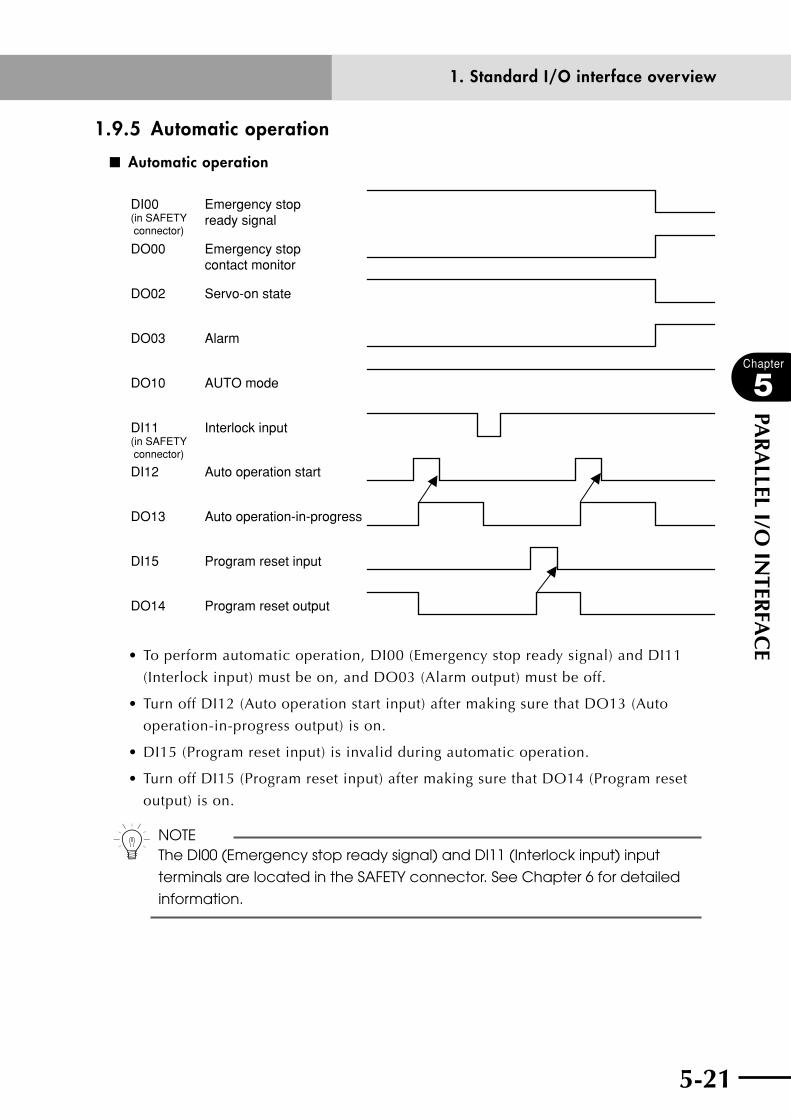
5-20 5-21
Chapter
5
PAR
ALLEL I/O
INTER
FAC
E
1.9.5 Automatic operation
■ Automatic operation
DI00(in SAFETY connector)
Emergency stop ready signal
DO00 Emergency stop contact monitor
DO02 Servo-on state
DO03 Alarm
DO10 AUTO mode
DI11(in SAFETY connector)
Interlock input
DI12 Auto operation start
DO13 Auto operation-in-progress
DI15 Program reset input
DO14 Program reset output
•Toperformautomaticoperation,DI00(Emergencystopreadysignal)andDI11
(Interlock input) must be on, and DO03 (Alarm output) must be off.
•TurnoffDI12(Autooperationstartinput)aftermakingsurethatDO13(Auto
operation-in-progress output) is on.
•DI15(Programresetinput)isinvalidduringautomaticoperation.
•TurnoffDI15(Programresetinput)aftermakingsurethatDO14(Programreset
output) is on.
n NOTEThe DI00 (Emergency stop ready signal) and DI11 (Interlock input) input
terminals are located in the SAFETY connector. See Chapter 6 for detailed
information.
1. Standard I/O interface overview
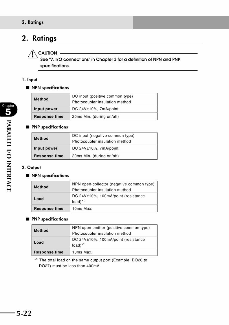
5-22
Chapter
5
PAR
ALLEL I/O
INTER
FAC
E
5-23
2. Ratings
cCAUTION See "7. I/O connections" in Chapter 3 for a definition of NPN and PNP specifications.
1. Input
■ NPN specifications
MethodDC input (positive common type)
Photocoupler insulation method
Input power DC 24V±10%, 7mA/point
Response time 20ms Min. (during on/off)
■ PNP specifications
MethodDC input (negative common type)
Photocoupler insulation method
Input power DC 24V±10%, 7mA/point
Response time 20ms Min. (during on/off)
2. Output
■ NPN specifications
MethodNPN open-collector (negative common type)
Photocoupler insulation method
LoadDC 24V±10%, 100mA/point (resistance
load)*1)
Response time 10ms Max.
■ PNP specifications
MethodNPN open emitter (positive common type)
Photocoupler insulation method
LoadDC 24V±10%, 100mA/point (resistance
load)*1)
Response time 10ms Max.
*1) The total load on the same output port (Example: DO20 to
DO27) must be less than 400mA.
2. Ratings
5-22 5-23
Chapter
5
PAR
ALLEL I/O
INTER
FAC
E
3. Precautions1. When using a dual-lead proximity sensor as an input signal, check whether or not it
is within input signal specifications.
If the sensor has a high residual voltage during on and off, this might cause
malfunctions.
2. Take noise preventive measures when using an inductive load such as a solenoid
valve as an output load. For example, connect a diode (high-speed type) in parallel
at both ends of a load, as a surge killer to protect against noise.
3. If a short occurs in the load or an excessive current flows, the internal over-
current protective circuit shuts off the interface circuit. Once this protective circuit
is activated, it is not possible to restore the previous state. In some cases, heat
generated inside might damage the internal circuits, so always draw current only
within the rated load.
4. As a noise prevention, keep the machine power cables separate and make sure
wires are well shielded.
5. Do not keep supplying the external 24V DC power to the I/O power connector
while controller power is off. The controller might malfunction if the external 24V is
continuously supplied.
3. Precautions

5-24
MEMO

Chapter 6 SAFETY I/O INTERFACE
Contents
1. SAFETY I/O interface overview 6-11.1 Power 6-1
1.2 Connector I/O signals 6-2
1.3 Connector terminal numbers 6-3
1.4 Emergency stop input signal connections 6-4
1.5 Dedicated input signal connections 6-10
1.6 Dedicated output signal connections 6-11
1.7 Input signal description 6-13
1.8 Meaning of output signals 6-14

6-1
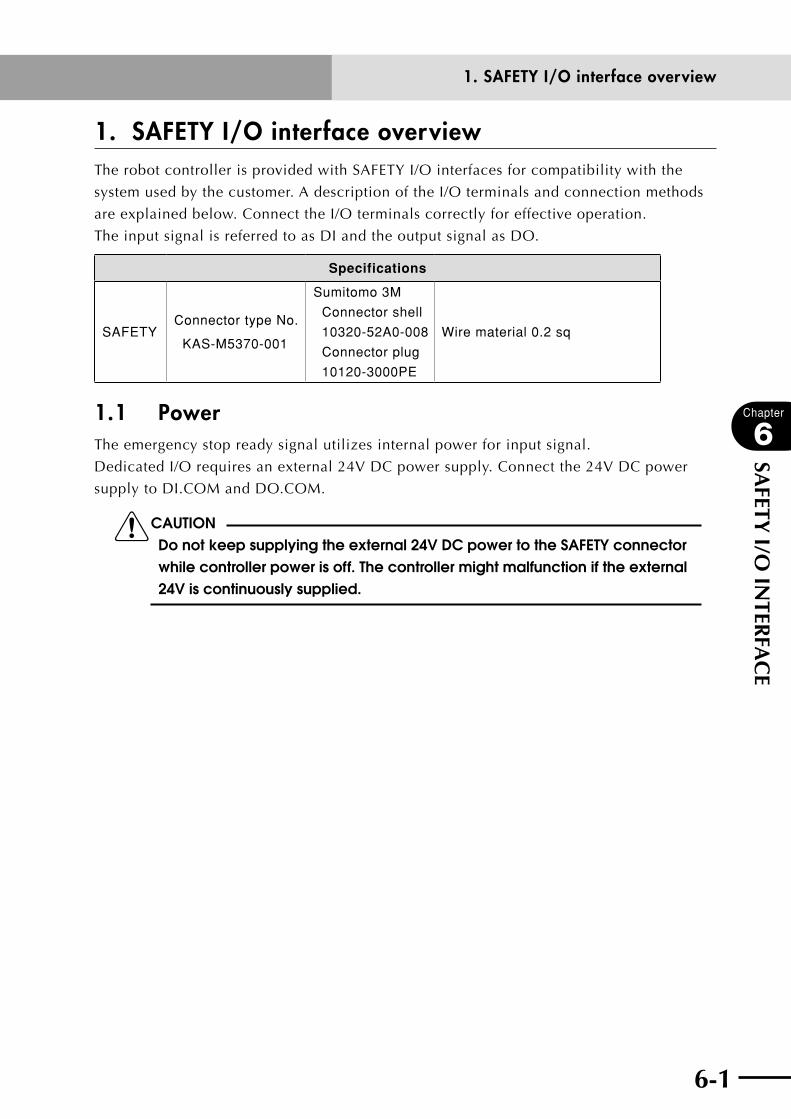
6-1
Chapter
6
SAFETY I/O
INTER
FAC
E
1. SAFETY I/O interface overviewThe robot controller is provided with SAFETY I/O interfaces for compatibility with the
system used by the customer. A description of the I/O terminals and connection methods
are explained below. Connect the I/O terminals correctly for effective operation.
The input signal is referred to as DI and the output signal as DO.
Specifications
SAFETYConnector type No.
KAS-M5370-001
Sumitomo 3M
Connector shell
10320-52A0-008
Connector plug
10120-3000PE
Wire material 0.2 sq
1.1 Power The emergency stop ready signal utilizes internal power for input signal.
Dedicated I/O requires an external 24V DC power supply. Connect the 24V DC power
supply to DI.COM and DO.COM.
cCAUTION Do not keep supplying the external 24V DC power to the SAFETY connector while controller power is off. The controller might malfunction if the external 24V is continuously supplied.
1. SAFETY I/O interface overview

6-2
Chapter
6
SAFETY I/O
INTER
FAC
E
6-3
1.2 Connector I/O signals PIN I/O symbol Name Remarks
1 DI.COM Dedicated input common
2 INTERLOCK (DI11) Interlock input Photocoupler input DC24V, 7mA
3 SERVICE (DI02) SERVICE mode input Photocoupler input DC24V, 7mA
4 DO.COM Dedicated output common
5 MPRDY Main power supply readyMechanical relay contact output
DC24V, 1A
6 SERVO OUT Servo-on state outputPhoto-MOS relay output DC24V,
100mA
7 NC No connection
8 KEY1 RPB key switch contact
9 KEY2 RPB key switch contact
10 24VGND E-STOP24V, GND
11 E-STOP24VPower supply for emergency
stop input
12 E-STOPRDY (DI00) Emergency stop ready signal
13 E-STOPIN1 Emergency stop input 1
14 E-STOPIN2 Emergency stop input 2
15 E-STOPIN3 Emergency stop input 3
16 E-STOPIN4 Emergency stop input 4
17 LCKIN1 Enable switch input 1
18 LCKIN2 Enable switch input 2
19 LCKIN3 Enable switch input 3
20 LCKIN4 Enable switch input 4
cCAUTION• onthesAfetYconnectorthatcomeswiththecontroller,pin1isshorted
to pin 10, pins 2, 3, 11 and 14 are shorted together, and pin 12 is shorted to pin 13. Use these pins to make an interlock circuit to ensure the system including the robot controller operates safely.
• donotconnectanexternaldc24vtoe-stop24v.• see"7.i/oconnections"inchapter3foradefinitionofnpnandpnp
specifications. • donotconnectanyexternalsignaltothencterminals.
1. SAFETY I/O interface overview
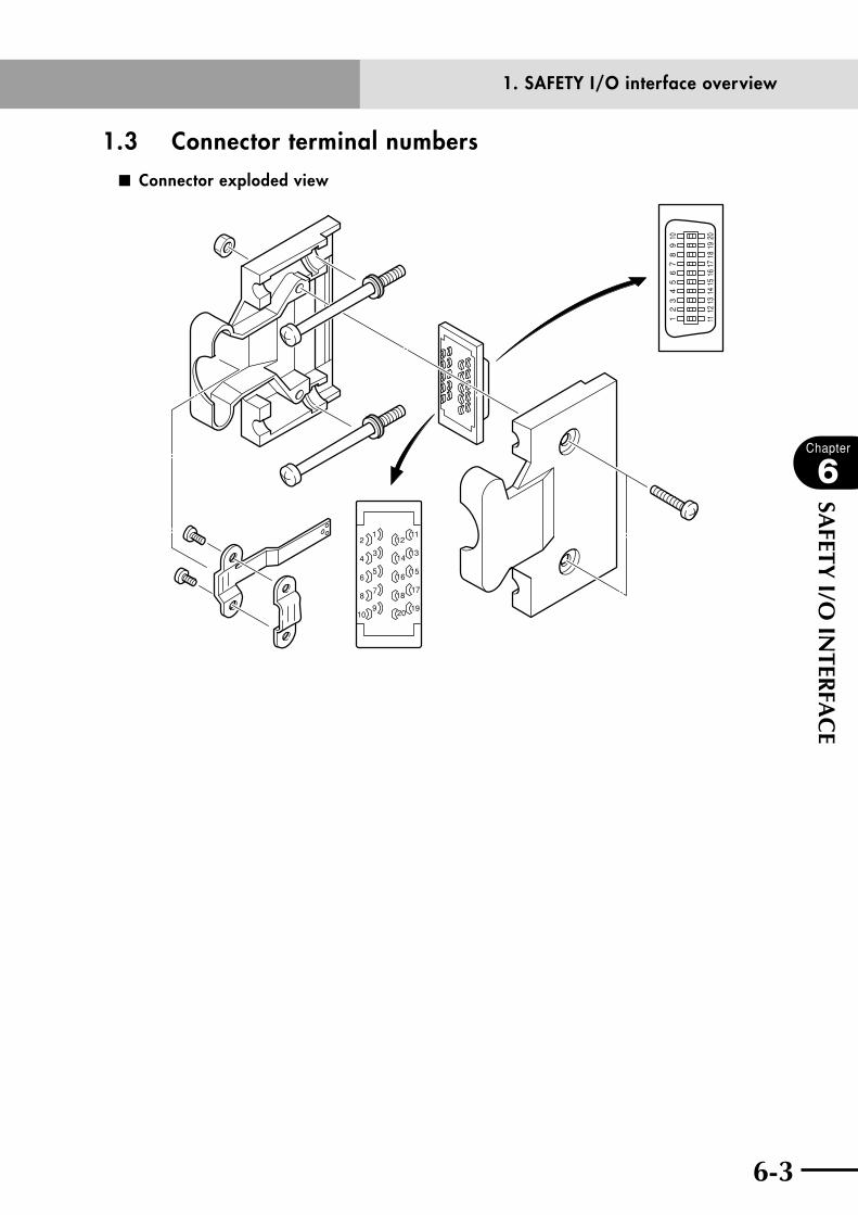
6-2 6-3
Chapter
6
SAFETY I/O
INTER
FAC
E
1.3 Connector terminal numbers ■ Connector exploded view
20
18
16
14
10
8
6
4
21
3
5
7
9
1112
13
15
17
19
12
34
56
78
910
1112
1314
1516
1718
1920
1. SAFETY I/O interface overview

6-4
Chapter
6
SAFETY I/O
INTER
FAC
E
6-5
1.4 Emergency stop input signal connections
cCAUTIONExternal emergency stop and the RPB emergency stop button are disabled when pins 11 and 12 on the SAFETY connector are directly shorted to each other. Make connections to ensure the system including the robot controller will always operate safely.
■ Emergency stop input signal connection (1) Connection when using the standard RPB with an external emergency stop circuit
RPB connector
SAFETY connector
DC24V
Internal control circuit
Motor drive circuit
Main power supply control circuitControl signal detection circuit
13 E-STOP1
14 E-STOP2
13 E-STOPIN1
14 E-STOPIN2
12 E-STOPRDY
11 E-STOP24V
RPB
External emergency stop circuit
N
L
1. SAFETY I/O interface overview

6-4 6-5
Chapter
6
SAFETY I/O
INTER
FAC
E
■ Emergency stop input signal connection (2) Connection when using the RPB-E (provided with an enable switch) with an external emergency stop circuit
Selector
1314RPB connector
SAFETY connector
13 E-STOPIN1
11 E-STOP24V
12 E-STOPRDY
RPB-E
External emergency stop circuit
DC24V
GND24V
Main power supply control circuitControl signal detection circuit
L
N
Motor drive circuit
Internal control circuit
1516171819202122
14 E-STOPIN2
10
1 DI.COM
3 SERVICEExternal service mode stop circuit
Enable switch
8 KEY1
9 KEY2
1. SAFETY I/O interface overview
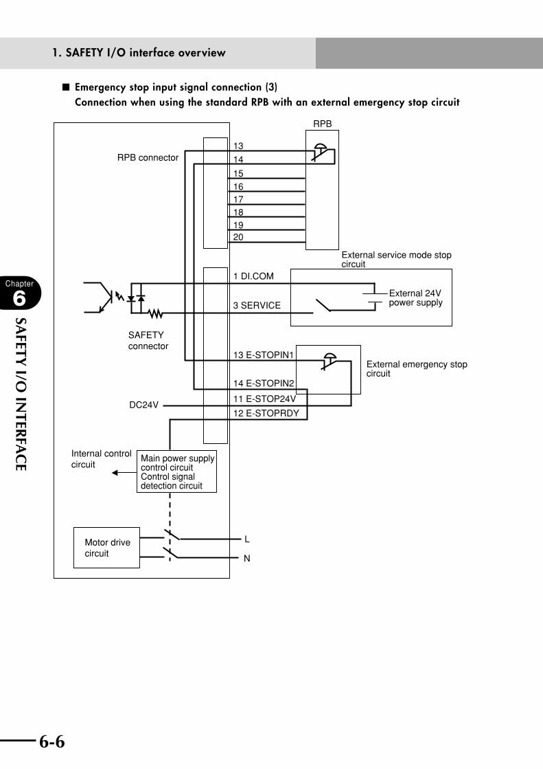
6-6
Chapter
6
SAFETY I/O
INTER
FAC
E
6-7
■ Emergency stop input signal connection (3) Connection when using the standard RPB with an external emergency stop circuit
13
14RPB connector
SAFETY connector
13 E-STOPIN1
11 E-STOP24V
12 E-STOPRDY
RPB
External emergency stop circuit
DC24V
Main power supply control circuitControl signal detection circuit
L
N
Motor drive circuit
Internal control circuit
151617181920
14 E-STOPIN2
1 DI.COM
3 SERVICE
External service mode stop circuit
External 24V power supply
1. SAFETY I/O interface overview

6-6 6-7
Chapter
6
SAFETY I/O
INTER
FAC
E
Operation description:
•TheRPBemergencystopswitchandexternalemergencystopswitchareconnected
in series.
a. In normal operation, E-STOP24V is connected to E-STOPRDY via the RPB
emergency stop switch and SAFETY connector, and the controller internal motor
power relay turns on.
b. When emergency stop is triggered, power to E-STOPRDY of the SAFETY connector
is cut off and the motor power supply turns off. Emergency stop is triggered if the
RPB and SAFETY connector are removed.
•Pins13and14,pins15and16,pins17and18,pins19and20,andpins21and
22 on the RPB connector are shorted in the RPB terminator that comes with the
robot controller.
•Pin1isshortedtopin10,pins2,3,11and14areshortedtogether,andpin12is
shorted to pin 13 in the SAFETY connector that comes with the robot controller.
cCAUTION • e-stoprdYrequiresatleast100mAfortherelayandphotocouplerdrive
current. • donotusedc24vforanythingotherthanemergencystop,interlockand
service mode inputs.
1. SAFETY I/O interface overview
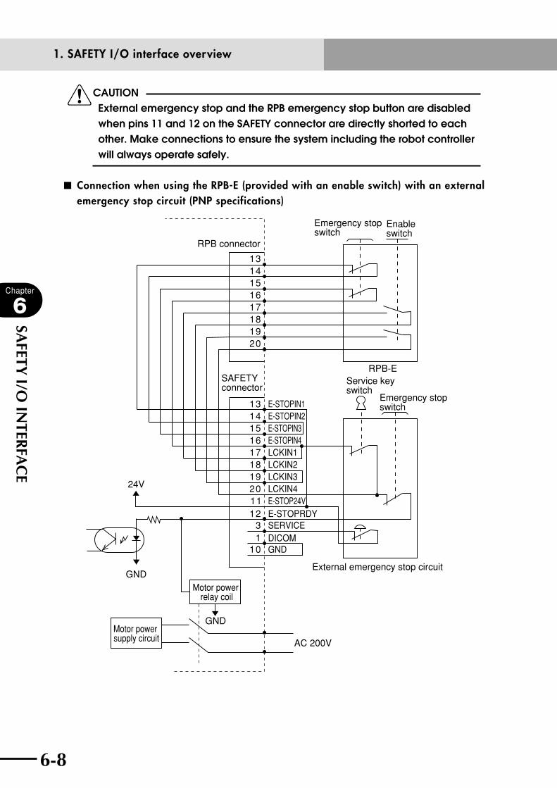
6-8
Chapter
6
SAFETY I/O
INTER
FAC
E
6-9
cCAUTION External emergency stop and the RPB emergency stop button are disabled when pins 11 and 12 on the SAFETY connector are directly shorted to each other. Make connections to ensure the system including the robot controller will always operate safely.
■ Connection when using the RPB-E (provided with an enable switch) with an external emergency stop circuit (PNP specifications)
GND
GND
24V
RPB connector
2019181716151413
1SERVICEE-STOPRDY
LCKIN4E-STOP24V
LCKIN3LCKIN2LCKIN1E-STOPIN4E-STOPIN3E-STOPIN2E-STOPIN1
312
10
112019181716151413
SAFETY connector
RPB-E
AC 200V
External emergency stop circuit
Emergency stop switch
Service key switch
Emergency stop switch
Enable switch
Motor power relay coil
Motor power supply circuit
GNDDICOM
1. SAFETY I/O interface overview

6-8 6-9
Chapter
6
SAFETY I/O
INTER
FAC
E
Operation description:
•TheRPB-Eemergencystopswitchandexternalemergencystopswitchare
connected in series. The enable switch is also connected in series to the RPB-E
emergency stop switch, but can be bypassed with the service key switch.
1. When the service key switch contact is closed:
The enable switch is inoperable at this point.
a. In normal operation, E-STOP24V is connected to E-STOPRDY via the RPB-E
emergency stop switch and SAFETY connector, and the motor power relay in the
controller turns on.
b. When emergency stop is triggered, power to E-STOPRDY of the SAFETY connector
is cut off and the motor power supply turns off. Emergency stop is triggered if the
RPB-E and SAFETY connector are removed.
2. When the service key switch contact is open:
The enable switch is operable at this point.
a. In normal operation, E-STOP24V is connected to E-STOPRDY via the RPB-E
emergency stop switch, enable switch and SAFETY connector, and the controller
internal motor power relay turns on.
b. When emergency stop is triggered, power to E-STOPRDY of the SAFETY connector
is cut off and the motor power supply turns off. Emergency stop is triggered if the
RPB-E and SAFETY connector are removed.
•Pins13and14,pins15and16,pins17and18,pins19and20,andpins21and
22 on the RPB connector are shorted in the RPB terminator that comes with the
robot controller.
•Pin1isshortedtopin10,pins2,3,11and14areshortedtogether,andpin12is
shorted to pin 13 in the SAFETY connector that comes with the robot controller.
cCAUTION • e-stoprdYrequiresatleast100mAfortherelayandphotocouplerdrive
current. • donotusee-stop24vforanythingotherthanemergencystop,interlock
and service mode inputs.
1. SAFETY I/O interface overview
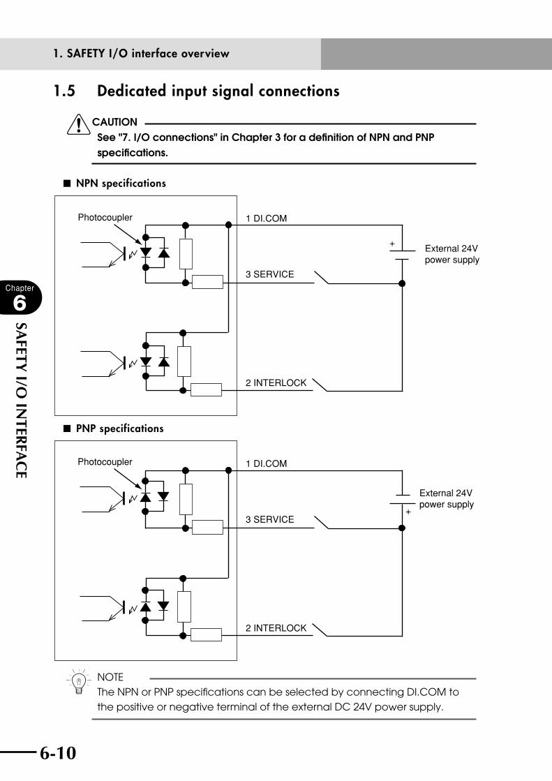
6-10
Chapter
6
SAFETY I/O
INTER
FAC
E
6-11
1.5 Dedicated input signal connections
cCAUTIONSee "7. I/O connections" in Chapter 3 for a definition of NPN and PNP specifications.
■ NPN specifications
+
1 DI.COM
3 SERVICE
2 INTERLOCK
Photocoupler
External 24V power supply
■ PNP specifications
+
1 DI.COM
3 SERVICE
2 INTERLOCK
Photocoupler
External 24V power supply
n NOTEThe NPN or PNP specifications can be selected by connecting DI.COM to the positive or negative terminal of the external DC 24V power supply.
1. SAFETY I/O interface overview
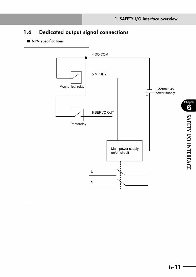
6-10 6-11
Chapter
6
SAFETY I/O
INTER
FAC
E
1.6 Dedicated output signal connections■ NPN specifications
4 DO.COM
5 MPRDY
6 SERVO OUT
Main power supply on/off circuit
L
N
+
Mechanical relay
Photorelay
External 24V power supply
1. SAFETY I/O interface overview

6-12
Chapter
6
SAFETY I/O
INTER
FAC
E
6-13
■ PNP specifications
4 DO.COM
5 MPRDY
6 SERVO OUT
Mechanical relay
Photorelay
Main power supply on/off circuit
L
N
External 24V power supply
+
1. SAFETY I/O interface overview

6-12 6-13
Chapter
6
SAFETY I/O
INTER
FAC
E
1.7 Input signal description
cCAUTIONSee "7. I/O connections" in Chapter 3 for a definition of NPN and PNP specifications.
n NOTE
• NPNandPNPspecificationsaredeterminedbytheDI.COMand
DO.COM inputs.
• A7mAinputcurrentisrequired.
1. DI02 Service mode input (SERVICE: DI02)
Service mode input can only be used on robot controllers with "SAFE" mode enabled.
When the DI02 contact is open (OFF), the robot controller service mode is set for
exclusive control for operating levels, operating speed limits and operating devices
conforming to the service mode parameter settings. Normal mode is enabled when
the DI02 contacts are closed (ON).
If a serial I/O option board is installed, "SERVICE" mode is entered when either one
of the SI02 or DI02 contact is open (OFF). (Normal mode is entered only when both
SI02 and DI02 contacts are closed (ON).)
If the service mode input is changed, the program being executed will pause or
ongoing robot jog movement will pause.
2. DI11 Interlock input (INTERLOCK: DI11)
Interlock input is used to temporarily stop robot movement during execution of a
program or manual operation of a robot. When the DI11 contact is opened (OFF), the
message "Interlock on" appears and the program and robot operation then stop. The
program cannot be executed and robot manual operation is disabled when the DI11
contact is open.
3. DI00 Emergency stop inputs (E-STOP24V, E-STOPRDY: DI00, E-STOPIN1, 2, 3, 4)
Emergency stop signal inputs are used when making the interlock circuit to ensure
the system including the robot controller will operate safely. Contacts must be closed
for the system to function normally. Refer to the connection examples in this chapter
when making actual connections.
Closing the emergency stop contact points (ON) allows turning on the servo power
supply. The servo power supply cannot be turned on when the emergency stop
contact points are open (OFF).
Emergency stop signal inputs 3 and 4 are valid only when an RPB-E (RPB compatible
with an enable switch) is used.
1. SAFETY I/O interface overview

6-14
Chapter
6
SAFETY I/O
INTER
FAC
E
4. Enable switch inputs 1, 2, 3, 4 (LCKIN1, 2, 3, 4)
Enable switch inputs are used when making the interlock circuit to ensure the system
including the robot controller will operate safely. Refer to the connection examples
in this chapter when making actual connections.
Enable switch inputs are valid only when an RPB-E (RPB compatible with an enable
switch) is used.
5. KEY switch inputs 1, 2 (KEY1, 2)
These are auxiliary contact inputs used to input signals such as a signal that
enables or disables the service mode. Use these inputs as needed according to your
specifications and application.
1.8 Meaning of output signals
1. MPRDY output
This output signal turns on when the controller is ready to receive the main power
input from an external device. This output is on before the servo turns on.
This signal turns off if an internal error occurs or the emergency stop input signal
turns off. Supply this output to a PLC or external device to allow it to determine the
on/off conditions of the main power supply.
2. SERVO OUT output
This output turns on when the servo turns on. This output is available even when only
one axis is at servo-on. This output turns off when all axis servos are off.
1. SAFETY I/O interface overview
Chapter 7 RS-232C INTERFACE
Contents
1. Communication overview 7-1
2. Communication function overview 7-2
3. Communication specifications 7-33.1 Connector 7-3
3.2 Transmission mode and communication parameters 7-5
3.3 Communication flow control 7-63.3.1 Flow control during transmit 7-6
3.3.2 Flow control during receive 7-6
3.4 Other caution items 7-7
3.5 Character code table 7-9
3.6 Connecting to a PC 7-10

7-1
7-1
Chapter
7
RS-232C
INTER
FAC
E
1. Communication overviewThe robot controller can communicate with external devices in the following two modes
using the RS-232C interface.
These modes can be used individually or jointly in a variety of applications using the RS-
232C interface.
(1) Data communication is performed by a communication command (SEND command)
in robot language
Example: SEND A TO CMU Variable A is transmitted to the external device.
SEND CMU TO P100 Point data P100 is received from the external device.
SEND CMU TO ALL All system memories are received.
The robot controller communicates in compliance with these commands.
(2) Various commands are transmitted directly through a communication port from the
external devices. These commands are called online commands.
If this function is used, some operations can be performed from an external device
just by turning on power to the robot controller.
Example: @AUTO Switches to "AUTO" mode.
@RUN Executes a program.
@READ PNT All point data are read out.
@MOVE P,P123,SPEED=30 Moves to point 123 at 30% of maximum speed.
n NOTE
On robot controllers with "SAFE" mode enabled, online commands might not
be used in service mode state depending on the operating device setting
in service mode.
1. Communication overview

7-2
Chapter
7
RS-232C
INTER
FAC
E
7-3
2. Communication function overviewThere are two types of robot controller communication modes, "ONLINE" and "OFFLINE".
(1) "OFFLINE" mode
In "OFFLINE" mode, the communication between the robot and external unit is
executed with SEND commands in the program.
• SEND command (robot → external unit)
SEND <source file> TO CMU
• SEND command (external unit → robot)
SEND CMU TO <destination file>
(2) "ONLINE" mode
In "ONLINE" mode, a variety of commands can be sent directly from the external unit
to the robot.
Commands sent directly from the external unit are called online commands. The
SEND command in a program is also valid even in "ONLINE" mode.
To set "ONLINE" mode, select "ONLINE" as a communication parameter in "SYSTEM"
mode. The ONLINE statement in the program can also be used to set "ONLINE" mode.
• ONLINE command format
@ [_] <online command> [<_command option>] <termination code>
* The <termination code> is a CR(=0Dh) code or CRLF (=0Dh+0Ah).
For detailed information on ONLINE commands, refer to the programming manual.
2. Communication function overview

7-2 7-3
Chapter
7
RS-232C
INTER
FAC
E
3. Communication specifications
3.1 Connector The RS-232C interface connector is located on the front panel of the robot controller as
shown below.
■ RS-232C interface
RCX221XM
YM
MOTOR
RGEN
TEMP
ACIN
N
L
L1
N1
SAFETY
RPB
ROBI/O
SD/COM
E-STOP
PIN11-12EXT.E-STOP
OP.1
OP.2
!
SRVERRRDY
6 1
9
5
Specifications of the RS-232C interface connector installed on the robot controller are
shown below.
1. A D-SUB 9-pin female connector is installed on the robot controller, so use a
connection cable with a D-SUB 9-pin male connector.
2. Pin arrangement of D-SUB 9-pin connector is as follows.
Pin No. Name Description Input/output
1 NC Not used
2 RXD Receive data Input
3 TXD Send data Output
4 NC Not used
5 GND Ground
6 NC Not used
7 RTS Request to send Output
8 CTS Permission to send Input
9 NC Not used
3. Communication specifications
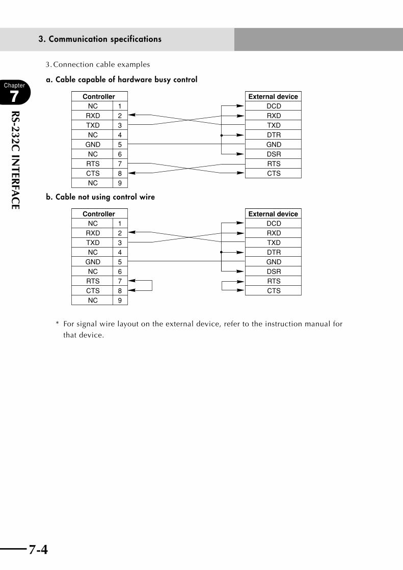
7-4
Chapter
7
RS-232C
INTER
FAC
E
7-5
3. Connection cable examples
a. Cable capable of hardware busy control
NCRXDTXDNC
GNDNCRTSCTSNC
123456789
ControllerDCDRXDTXDDTRGNDDSRRTSCTS
External device
b. Cable not using control wire
NCRXDTXDNC
GNDNCRTSCTSNC
123456789
ControllerDCDRXDTXDDTRGNDDSRRTSCTS
External device
* For signal wire layout on the external device, refer to the instruction manual for
that device.
3. Communication specifications
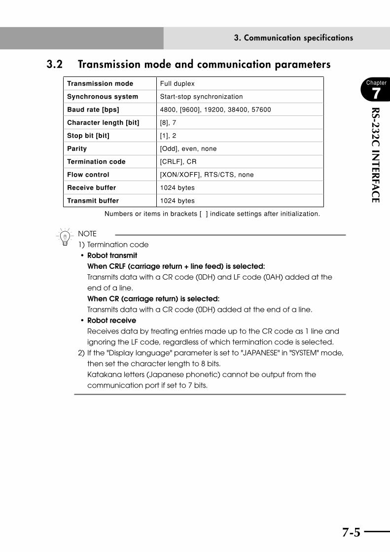
7-4 7-5
Chapter
7
RS-232C
INTER
FAC
E
3.2 Transmission mode and communication parameters
Transmission mode Full duplex
Synchronous system Start-stop synchronization
Baud rate [bps] 4800, [9600], 19200, 38400, 57600
Character length [bit] [8], 7
Stop bit [bit] [1], 2
Parity [Odd], even, none
Termination code [CRLF], CR
Flow control [XON/XOFF], RTS/CTS, none
Receive buffer 1024 bytes
Transmit buffer 1024 bytes
Numbers or items in brackets [ ] indicate settings after initialization.
n NOTE
1) Termination code
•robottransmit whencrlf(carriagereturn+linefeed)isselected: Transmits data with a CR code (0DH) and LF code (0AH) added at the
end of a line.
When CR (carriage return) is selected: Transmits data with a CR code (0DH) added at the end of a line.
•robotreceive
Receives data by treating entries made up to the CR code as 1 line and
ignoring the LF code, regardless of which termination code is selected.
2) If the "Display language" parameter is set to "JAPANESE" in "SYSTEM" mode,
then set the character length to 8 bits.
Katakana letters (Japanese phonetic) cannot be output from the
communication port if set to 7 bits.
3. Communication specifications

7-6
Chapter
7
RS-232C
INTER
FAC
E
7-7
3.3 Communication flow control Software flow control (XON/XOFF) and hardware flow control (RTS/CTS) methods can be
selected by specifying the communication parameters.
n NOTE
When flow control is set to "XON/XOFF" or "none", CTS status does not affect
transmission. RTS is always on.
When flow control is set to "RTS/CTS" or "none", receiving XON and XOFF does
not affect transmission.
When flow control is set to "none", part of receive data might be lost.
3.3.1 Flow control during transmit Data transmission temporarily stops when the other party's device is in receive busy
status.
Communication parameter Operation during transmit
XON/XOFFStops transmission when XOFF (13H) is received.
Resumes transmission when XON (11H) is received.
RTS/CTS Stops transmission while CTS is off.
None Does not perform flow control during transmit.
3.3.2 Flow control during receive This notifies the other party's device that the controller is in receive busy status.
Communication parameter Operation during transmit
XON/XOFF
Transmits XOFF (13H) when available space in
receive buffer falls below a certain capacity.
Transmits XON (11H) when receive buffer is empty.
RTS/CTS
Turns RTS off when available space in receive buffer
falls below a certain capacity.
Turns RTS on when receive buffer is empty.
None Does not perform flow control during receive.
3. Communication specifications

7-6 7-7
Chapter
7
RS-232C
INTER
FAC
E
3.4 Other caution items 1) The controller allows receiving data as long as the receive buffer has a free area.
The receive buffer is cleared in the following cases.
•Whenthepowerwasturnedoffandturnedbackon.
•Whentheprogramwasreset.
•WhenanONLINEstatementorOFFLINEstatementwasexecutedaccordingtothe
robot language.
•Whenthecommunicationparameterwaschangedin"SYSTEM"modeorwhen
initialization was executed.
2) Turning on an external device might send incorrect data to the robot controller which
is ready to receive data when the power is turned on. That incorrect data might then
be stored in the receive buffer if the controller is turned on prior to the external
device and cause communication errors.
In such a case,
•Resettheprogrambeforeprogramexecution.
•ClearthereceivebufferbyplacinganONLINEstatementorOFFLINEstatementat
the top of the program.
•Turntheexternaldeviceonbeforeturningthecontrolleron.
3) When the external device does not support handshake protocols (BUSY control, XON/
XOFF control), the data processing speed becomes slower than the communication
speed, causing a communication error. In this case, take countermeasures such as
reducing the communication speed (baud rate).
4) When the communication speed is set at a high rate, communication errors might
occur due to external noise or other factors. In this case, take countermeasures such
as reducing the communication speed.
5) There is no response to external transmission during direct command execution or
point trace execution in "AUTO" mode. A response is issued after execution.
6) Improper connection to an external device might cause electrical shocks, controller
malfunctions or external device malfunctions or breakdowns, depending on the
external device type and its operating conditions.
Always comply with the following points when connecting an external device.
1. When the external device has a ground wire, be sure to ground it properly.
2. If using an external device that does not have a ground wire or protective ground
terminal, make sure that its structure is designed to protect from electrical shock.
3. Communication specifications
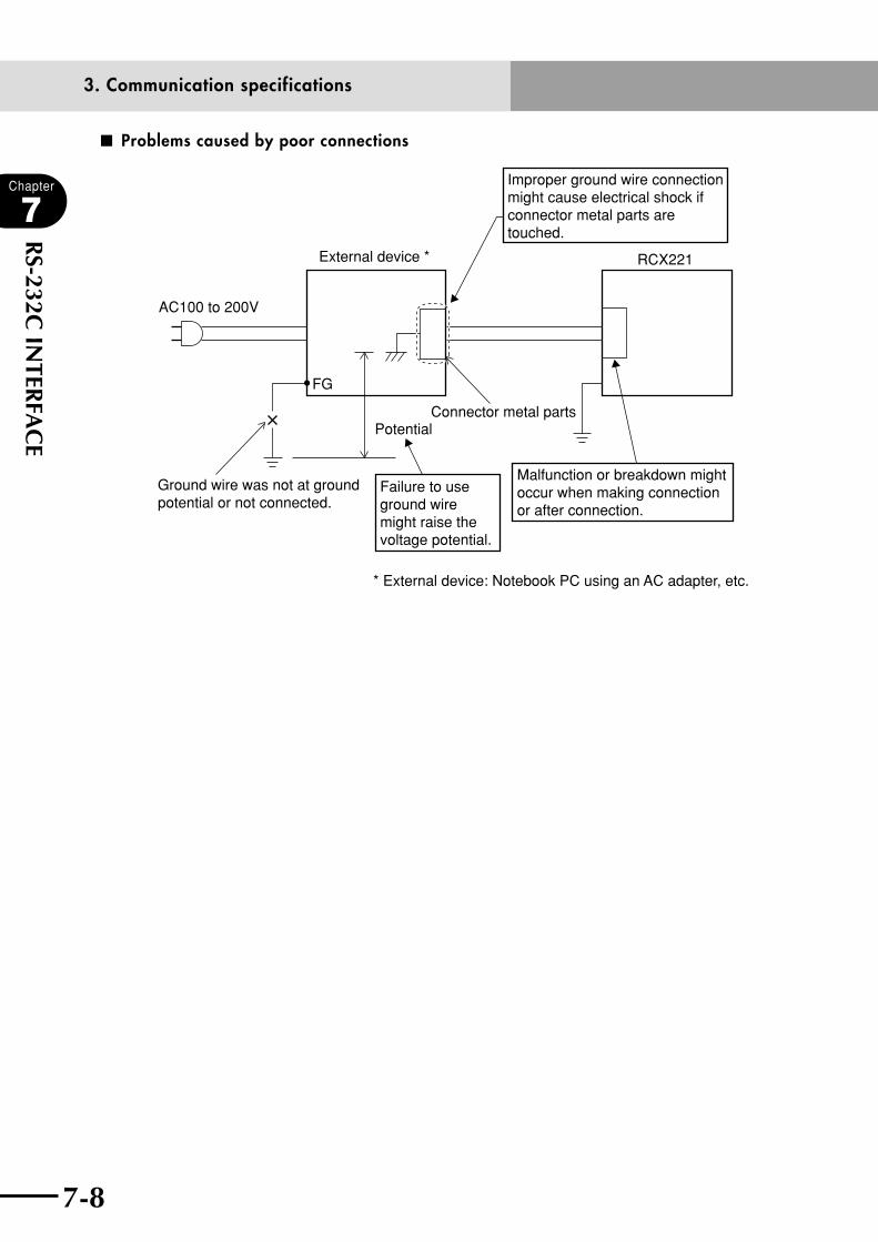
7-8
Chapter
7
RS-232C
INTER
FAC
E
7-9
■ Problems caused by poor connections
External device * RCX221
Connector metal parts
FG
Potential
Ground wire was not at ground potential or not connected.
Improper ground wire connection might cause electrical shock if connector metal parts are touched.
Malfunction or breakdown might occur when making connection or after connection.
Failure to use ground wire might raise the voltage potential.
* External device: Notebook PC using an AC adapter, etc.
AC100 to 200V
3. Communication specifications

7-8 7-9
Chapter
7
RS-232C
INTER
FAC
E
3.5 Character code tableHEX. 0- 1- 2- 3- 4- 5- 6- 7- 8- 9- A- B- C- D- E- F-
-0 SP 0 @ P p ー タ ミ
-1 XON ! 1 A Q a q 。 ア チ ム
-2 " 2 B R b r 「 イ ツ メ
-3 STOP XOFF # 3 C S c s 」 ウ テ モ
-4 $ 4 D T d t 、 エ ト ヤ
-5 % 5 E U e u . オ ナ ユ
-6 & 6 F V f v ヲ カ ニ ヨ
-7 ' 7 G W g w ァ キ ヌ ラ
-8 BS ( 8 H X h x ィ ク ネ リ
-9 TAB ) 9 I Y i y ゥ ケ ノ ル
-A LF EOF * : J Z j z ェ コ ハ レ
-B + ; K [ k { ォ サ ヒ ロ
-C , < L ¥ l l l ヤ シ フ ワ
-D CR - = M ] m } ユ ス ヘ ン
-E . > N ^ n ~ ヨ セ ホ "
-F / ? O o ツ ソ マ 。
Note 1: The above character codes are written in hexadecimal.
Note 2: SP indicates a blank space.
Note 3: Only capital letters can be used for robot language. Small letters are used
for program comments, etc. However, these cannot be entered on the RPB.
Note 4: BS deletes the preceding character in the receive buffer.
Note 5: TAB is replaced with one space.
3. Communication specifications
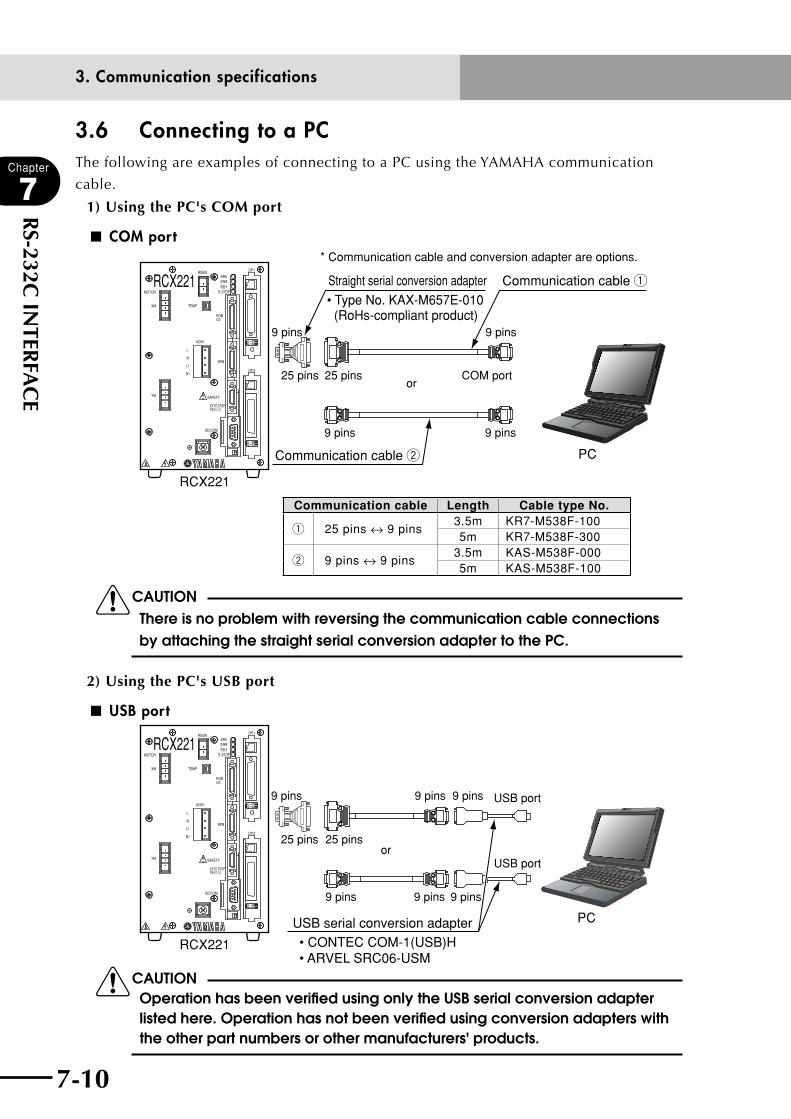
7-10
Chapter
7
RS-232C
INTER
FAC
E
3.6 Connecting to a PC The following are examples of connecting to a PC using the YAMAHA communication
cable.
1) Using the PC's COM port
■ COM port
PC
RCX221
RCX221XM
YM
MOTOR
RGEN
TEMP
ACIN
N
L
L1
N1
SAFETY
RPB
ROBI/O
SD/COM
E-STOP
PIN11-12EXT.E-STOP
OP.1
OP.2
!
SRVERRRDY
25 pins 25 pinsor
9 pins
9 pins 9 pins
9 pins
COM port
Communication cable w
Communication cable q
* Communication cable and conversion adapter are options.
Straight serial conversion adapter
• Type No. KAX-M657E-010 (RoHs-compliant product)
Communication cable Length Cable type No.
q 25 pins ↔ 9 pins3.5m KR7-M538F-1005m KR7-M538F-300
w 9 pins ↔ 9 pins3.5m KAS-M538F-0005m KAS-M538F-100
cCAUTION There is no problem with reversing the communication cable connections by attaching the straight serial conversion adapter to the PC.
2) Using the PC's USB port
■ USB port
PC
RCX221
RCX221XM
YM
MOTOR
RGEN
TEMP
ACIN
N
L
L1
N1
SAFETY
RPB
ROBI/O
SD/COM
E-STOP
PIN11-12EXT.E-STOP
OP.1
OP.2
!
SRVERRRDY
USB serial conversion adapter• CONTEC COM-1(USB)H• ARVEL SRC06-USM
25 pins 25 pinsor
9 pins 9 pins9 pins
9 pins
USB port
USB port
9 pins 9 pins
cCAUTION Operation has been verified using only the USB serial conversion adapter listed here. Operation has not been verified using conversion adapters with the other part numbers or other manufacturers' products.
3. Communication specifications

Chapter 8 SPECIFICATIONS
Contents
1. Controller basic specifications 8-1
2. Controller basic functions 8-3
3. Controller external view 8-43.1 RCX221 external view 8-4
3.2 RCX221HP external view 8-5
4. RPB basic specifications and external view 8-6

8-1

8-1
Chapter
8
SPECIFIC
ATIO
NS
1. Controller basic specificationsItem RCX221 RCX221 HP
Basic specifications
Applicable robotsYAMAHA single-axis robots, linear single-axis robots, cartesian robots, P&P robots
Connectable motor capacity Less than 800W (2 axes total) 800 to 1200W (2 axes total)
Power capacity 1700VA 2400VA
DimensionsW130 × H210 × D158 mm (main unit)
W158 × H210 × D158 mm (main unit)
Weight 2.9kg (main unit) 3.1kg (main unit)
Power supply voltage Single phase 200 to 230V AC ±10% (50/60Hz)
Axis control
No. of controllable axes 2 axes maximum (simultaneous control: 2 axes)
Drive method AC full digital servo
Position detection method Resolver, Resolver or magnetic linear scale
Control methodPTP motion (point to point), ARCH motion, linear interpolation, circular interpolation
Coordinate system Joint coordinates, Cartesian coordinates
Position display units Pulses, mm (millimeters), deg (degrees)
Speed setting 1 to 100% (1% increments; setting can be changed by program)
Acceleration/deceleration setting
Automatic acceleration setting by robot model and tip weight parameter Setting by accel coefficient and decel. rate parameters (1% steps) (Can be changed by programming.)
Programming
Program language YAMAHA BASIC conforming to JIS B8439 (SLIM language)
Multitask 8 tasks maximum
Sequence program 1 program
Memory capacity364KB (Total of program and point data) (Available size for program when maximum number of points is used: 84KB)
Programs
100 programs (maximum number of programs) 9999 lines (maximum lines per program) 98KB (maximum capacity per program, maximum capacity per object program)
Points 10000 points (maximum number of points)
Point teachingMDI (coordinate data input), direct teaching, teaching playback, offline teaching (data input from external unit)
System backup(Internal memory backup ) Lithium battery (Service life is about 4 years at 0 to 40°C)
Internal flash memory 512KB (ALL data only)
External memory backup SD memory card
1. Controller basic specifications

8-2
Chapter
8
SPECIFIC
ATIO
NS
8-3
Item RCX221 RCX221 HP
External I/O
STD.DIOInput Dedicated 10 points, general-purpose 16 points
Output Dedicated 12 points, general-purpose 8 points
SAFETYInput
Emergency stop input Service mode input Interlock input Enable switch input (enabled only when RPB-E is used)
Output Servo ON status output Main power ON ready output
Brake output Relay contact
Origin sensor input Connectable to 24V DC B-contact (normally closed) sensor
External communicationRS-232C : 1 channel (D-SUB 9-pin female connector) RS-422 : 1 channel (for RPB only)
Regenerative unit connection
RGEN connector, TEMP connector
General specifications
Operating temperature 0°C to 40°C
Storage temperature -10°C to 65°C
Operating humidity 35 to 85% RH (no condensation)
Noise immunity IEC61000-4-4 Level 3
Protective structure IP10
Options
Op
tion
s bo
ard
Option slot 2 slots (including STD.DIO)
Parallel I/O board
STD.DIO
Dedicated input 10 points, dedicated output 12 points General-purpose input 16 points, general-purpose output 8 points (compatible with NPN/PNP specifications)
OP.DIOGeneral-purpose input 24 points/board, output 16 points/board (2 boards maximum, (including STD.DIO) compatible with NPN/PNP specifications)
CC-Link boardDedicated input 16 points, dedicated output 16 points General-purpose input 96 points, general-purpose output 96 points
DeviceNet boardDedicated input 16 points, dedicated output 16 points General-purpose input 96 points, general-purpose output 96 points
PROFIBUS boardDedicated input 16 points, dedicated output 16 points General-purpose input 96 points, general-purpose output 96 points
Ethernet board Conforms to IEEE802.3, 10Mbps (10BASE-T)
Programming box RPB, RPB-E
Regenerative unit RG2
PC software VIP+, VIP
cCAUTION • specificationsandappearancearesubjecttochangewithoutprior
notice.• see"7.i/oconnections"inchapter3foradefinitionofnpnandpnp
specifications.
1. Controller basic specifications
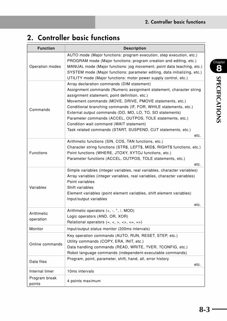
8-2 8-3
Chapter
8
SPECIFIC
ATIO
NS
2. Controller basic functionsFunction Description
Operation modes
AUTO mode (Major functions: program execution, step execution, etc.)
PROGRAM mode (Major functions: program creation and editing, etc.)
MANUAL mode (Major functions: jog movement, point data teaching, etc.)
SYSTEM mode (Major functions: parameter editing, data initializing, etc.)
UTILITY mode (Major functions: motor power supply control, etc.)
Commands
Array declaration commands (DIM statement)
Assignment commands (Numeric assignment statement, character string
assignment statement, point definition, etc.)
Movement commands (MOVE, DRIVE, PMOVE statements, etc.)
Conditional branching commands (IF, FOR, WHILE statements, etc.)
External output commands (DO, MO, LO, TO, SO statements)
Parameter commands (ACCEL, OUTPOS, TOLE statements, etc.)
Condition wait command (WAIT statement)
Task related commands (START, SUSPEND, CUT statements, etc.)
etc.
Functions
Arithmetic functions (SIN, COS, TAN functions, etc.)
Character string functions (STR$, LEFT$, MID$, RIGHT$ functions, etc.)
Point functions (WHERE, JTOXY, XYTOJ functions, etc.)
Parameter functions (ACCEL, OUTPOS, TOLE statements, etc.)
etc.
Variables
Simple variables (integer variables, real variables, character variables)
Array variables (integer variables, real variables, character variables)
Point variables
Shift variables
Element variables (point element variables, shift element variables)
Input/output variables
etc.
Arithmetic
operation
Arithmetic operators (+, -, *, /, MOD)
Logic operators (AND, OR, XOR)
Relational operators (=, <, >, <>, <=, =>)
Monitor Input/output status monitor (200ms intervals)
Online commands
Key operation commands (AUTO, RUN, RESET, STEP, etc.)
Utility commands (COPY, ERA, INIT, etc.)
Data handling commands (READ, WRITE, ?VER, ?CONFIG, etc.)
Robot language commands (independent-executable commands)
Data filesProgram, point, parameter, shift, hand, all, error history
etc.
Internal timer 10ms intervals
Program break
points4 points maximum
2. Controller basic functions
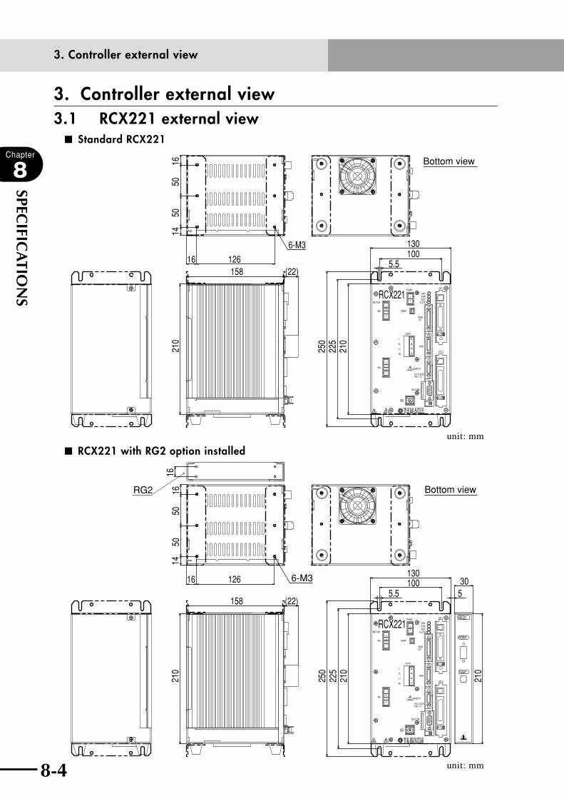
8-4
Chapter
8
SPECIFIC
ATIO
NS
8-5
3. Controller external view3.1 RCX221 external view
■ Standard RCX221
Bottom view
RCX221XM
YM
MOTOR
RGEN
TEMP
ACIN
N
L
L1
N1
SAFETY
SRVERR
RPB
ROBI/O
SD/COM
RDYE-STOP
PIN11-12EXT.E-STOP
OP.1
OP.2
!
16
1650
5014
126
130100
250
210
225
(22)158
210
6-M3
5.5
unit: mm
■ RCX221 with RG2 option installed
Bottom view
RG2
TEMP
RGEN
RCX221
RG2
XM
YM
MOTOR
RGEN
TEMP
ACIN
N
L
L1
N1
SAFETY
SRVERR
RPB
ROBI/O
SD/COM
RDYE-STOP
PIN11-12EXT.E-STOP
OP.1
OP.2
!
16
1650
50
126130100
5.5 5
250
210
225
(22)158
210
210
30
16
6-M3
14
unit: mm
3. Controller external view
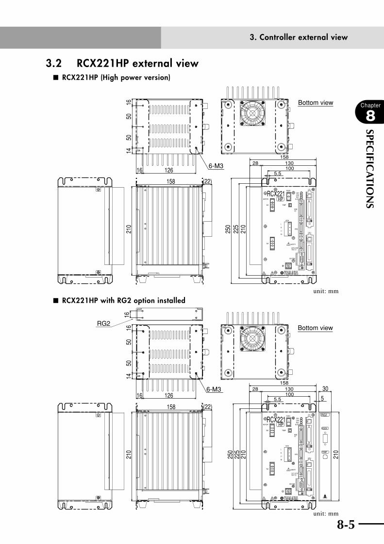
8-4 8-5
Chapter
8
SPECIFIC
ATIO
NS
3.2 RCX221HP external view■ RCX221HP (High power version)
5.5
Bottom view
HPRCX221
XM
YM
MOTOR
RGEN
TEMP
ACIN
N
L
L1
N1
SAFETY
SRVERR
RPB
ROBI/O
SD/COM
RDYE-STOP
PIN11-12EXT.E-STOP
OP.1
OP.2
!
16
1650
50
126
210
158 (22)
130158
100
250
210
28
225
6-M3
14
unit: mm
■ RCX221HP with RG2 option installed
5.5
130158
10028
5
Bottom view
HP
RG2
TEMP
RGEN
6-M3
RCX221XM
YM
MOTOR
RGEN
TEMP
ACIN
N
L
L1
N1
SAFETY
SRVERR
RPB
ROBI/O
SD/COM
RDYE-STOP
PIN11-12EXT.E-STOP
OP.1
OP.2
!
16
1650
50
126
210
158 (22)
250
210
30
210
16
225
RG2
14
unit: mm
3. Controller external view
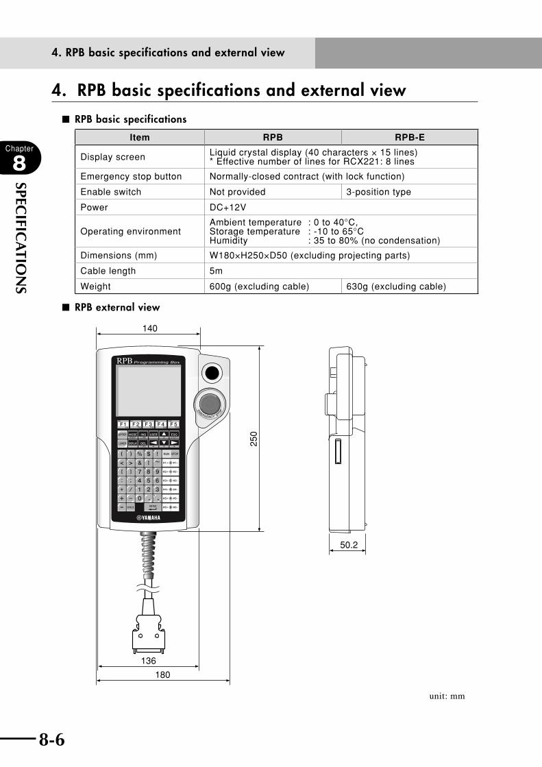
8-6
Chapter
8
SPECIFIC
ATIO
NS
8-7
4. RPB basic specifications and external view
■ RPB basic specifications
Item RPB RPB-E
Display screen Liquid crystal display (40 characters × 15 lines) * Effective number of lines for RCX221: 8 lines
Emergency stop button Normally-closed contract (with lock function)
Enable switch Not provided 3-position type
Power DC+12V
Operating environmentAmbient temperature : 0 to 40°C, Storage temperature : -10 to 65°C Humidity : 35 to 80% (no condensation)
Dimensions (mm) W180×H250×D50 (excluding projecting parts)
Cable length 5m
Weight 600g (excluding cable) 630g (excluding cable)
■ RPB external view
136
180
250
50.2
140
unit: mm
4. RPB basic specifications and external view
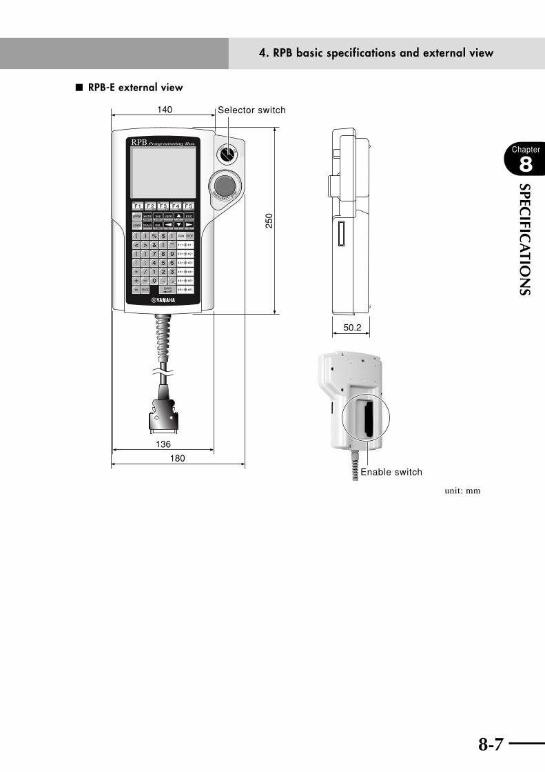
8-6 8-7
Chapter
8
SPECIFIC
ATIO
NS
■ RPB-E external view
136
180
250
50.2
140 Selector switch
Enable switch
unit: mm
4. RPB basic specifications and external view

8-8
MEMO

Chapter 9 TROUBLESHOOTING
Contents
1. Error Messages 9-11.1 Robot controller error messages 9-1
[ 0] Warnings and messages 9-3
[ 1] Warnings (error history entry) 9-5
[ 2] Robot operating area errors 9-6
[ 3] Program file operating errors 9-9
[ 4] Data entry and edit errors 9-12
[ 5] Robot language syntax (compiling) errors 9-12
[ 6] Robot language execution errors 9-21
[ 9] Memory errors 9-26
[10] System setting or hardware errors 9-29
[12] I/O and option board errors 9-31
[13] RPB errors 9-35
[14] RS-232C communication errors 9-36
[15] Memory card errors 9-38
[17] Motor control errors 9-40
[19] YC-Link (SR1) related error 9-47
[21] Major software errors 9-53
[22] Major hardware errors 9-55
1.2 RPB Error Messages 9-61
2. Troubleshooting 9-632.1 When trouble occurs 9-63
2.2 Acquiring error information 9-642.2.1 Acquiring information from the RPB 9-64
2.2.2 Acquiring information from the RS-232C 9-64
2.3 Troubleshooting checkpoints 9-65

9-1
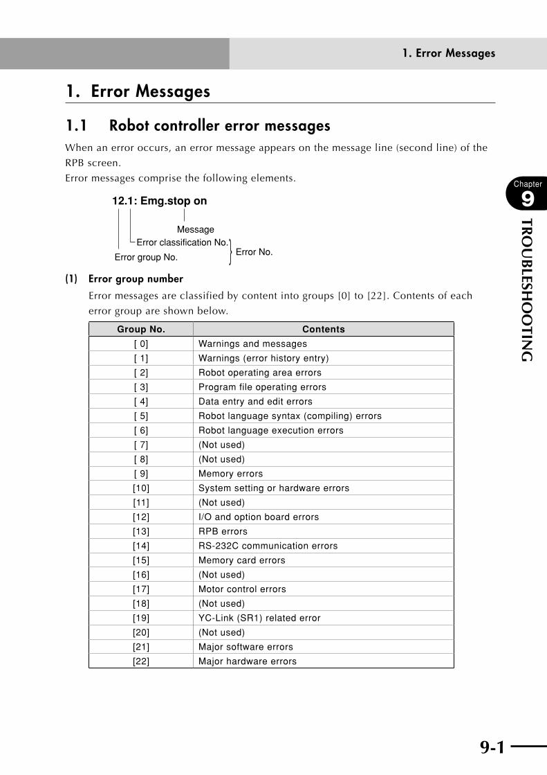
9-1
Chapter
9
TRO
UB
LESHO
OTIN
G
1. Error Messages
1.1 Robot controller error messagesWhen an error occurs, an error message appears on the message line (second line) of the
RPB screen.
Error messages comprise the following elements.
12.1: Emg.stop on
MessageError classification No.
Error No.Error group No.
(1) Error group number
Error messages are classified by content into groups [0] to [22]. Contents of each
error group are shown below.
Group No. Contents
[ 0] Warnings and messages
[ 1] Warnings (error history entry)
[ 2] Robot operating area errors
[ 3] Program file operating errors
[ 4] Data entry and edit errors
[ 5] Robot language syntax (compiling) errors
[ 6] Robot language execution errors
[ 7] (Not used)
[ 8] (Not used)
[ 9] Memory errors
[10] System setting or hardware errors
[11] (Not used)
[12] I/O and option board errors
[13] RPB errors
[14] RS-232C communication errors
[15] Memory card errors
[16] (Not used)
[17] Motor control errors
[18] (Not used)
[19] YC-Link (SR1) related error
[20] (Not used)
[21] Major software errors
[22] Major hardware errors
1. Error Messages

9-2
Chapter
9
TRO
UB
LESHO
OTIN
G
9-3
[Format]
Error No. : [<location where error occurred>,] error message
... Displays the error message on screen.
Code : ... Displays the error code in hexadecimal numbers.
Meaning/Cause : ... Displays the meaning and cause of the error.
Action : ... Displays a message explaining action needed to eliminate or
avoid error status.
Dedicated output : ... Refer to "(2) Dedicated output status".
* The beginning of the error message may sometimes include information on
the location (axis, option unit, etc.) where the error occurred. An "M" in this
information indicates the main group axis No., an "S" indicates the sub group axis
No., a "D" indicates the driver axis No., and an "OP" indicates the option unit slot
No.
For example, a message "2.1:M1, Soft limit over" indicates that the preset soft
limit values have been exceeded on axis 1 of the main group robot. Likewise, the
message, "17.4:D2, Overload" indicates that an overload has occurred in axis 2 of
the driver unit. The axes viewed by the robot and the axes viewed by the driver are
normally a one-to-one match with each other, but when dual-drive axes are used,
one axis viewed by the robot may sometimes be treated as 2 axes by the driver.
(2) Dedicated output status
Dedicated output status items described below in *1 to *3 show the following
contents.
*1 ... CPU stop•TurnthepowerONagaintoreset.
DO 01a (CPU OK) = OFF
DO 02a (SERVO ON) = OFF
DO 03a (ALARM) = ON
*2 ... Driver stop•TurnthepowerONagaintoreset.
DO 02a (SERVO ON) = OFF
DO 03a (ALARM) = ON
*3 ... Servo stop•TurnthepowerONagainin"UTILITY"modetoreset.
DO 02a (SERVO ON) = OFF
DO 03a (ALARM) = ON
cCAUTIONWhen an error cannot be cancelled, contact your YAMAHA sales dealer.
1. Error Messages
9-2 9-3
Chapter
9
TRO
UB
LESHO
OTIN
G
[ 0] Warnings and messages
0.0 : Undefined errorCode : &H0000
Meaning/Cause : Undefined system error.
Action : Contact our company.
0.1 : Origin incomplete
* If the cause of the Origin incomplete error can be pinpointed, an error
code will be attached in parentheses at the end.
Code : &H0001
Meaning/Cause : a. Return-to-origin is incomplete because return-to-origin has
not been performed. So you …
•cannotexecuteprogramsandcommands.
•cannotperformpointteaching.
•cannotperformmanualCartesianmovement(mmunits).
b. ROB I/O cable was removed or disconnected.
c. Return-to-origin or absolute search operation was interrupted.
d. System generation was changed or parameters initialized. Or
parameters for specifying the origin position such as for the
return-to-origin direction or axis polarity were changed.
(Equivalent to writing ALL or PRM file on controller.)
Action : Perform return-to-origin to completion.
0.2 : RunningCode : &H0002
Meaning/Cause : Program or command is running.
Action : ---
0.3 : Program terminated by "HALT"Code : &H0003
Meaning/Cause : Program execution was terminated by a HALT command.
Action : ---
0.4 : CompilingCode : &H0004
Meaning/Cause : Robot language compiling (making an object program) is in
progress.
Action : ---
[ 0] Warnings and messages
9-4
Chapter
9
TRO
UB
LESHO
OTIN
G
9-5
0.5 : BusyCode : &H0005
Meaning/Cause : Data is being saved on a memory card or internal ROM.
Action : ---
0.6 : Program suspended by "HOLD"Code : &H0006
Meaning/Cause : Program execution was interrupted by a HOLD command.
Action : Press to cancel hold condition and start running the
program from the next command.
0.7 : Turn on power againCode : &H0007
Meaning/Cause : a. System generation was performed due to a robot change, etc.
b. Parameter was changed by data transfer.
c. System generation data was destroyed.
d. Error occurred when servo was turned ON.
Action : Turn the controller on again.
0.8 : Try againCode : &H0008
Meaning/Cause : Operation failed.
Action : Try again.
0.9 : Arrived at breakpointCode : &H0009
Meaning/Cause : Break point was reached during program execution.
Action : ---
0.10 : INC. motor disconnectedCode : &H000A
Meaning/Cause : Return-to-origin command was attempted on an absolute axis
or an axis that does not exist.
Action : 1. Select the correct axis.
2. Check the system generation data.
0.11 : ABS. motor disconnectedCode : &H000B
Meaning/Cause : Absolute reset was attempted on an incremental mode axis or
semi-absolute mode axis, or an axis that does not exist.
Action : 1. Specify the correct axis.
2. Check the system generation data.
[ 0] Warnings and messages

9-4 9-5
Chapter
9
TRO
UB
LESHO
OTIN
G
0.14 : Stop executedCode : &H000E
Meaning/Cause : Stop was commanded while executing a direct command so
operation was stopped.
Action : ---
0.15 : Can't execute while servo onCode : &H000F
Meaning/Cause : Writing in "ALL" or "PRM" files was attempted during servo-on.
"ALL" or "PRM" files cannot be written in servo-on.
Action : Turn off the servo before writing files.
0.16 : Changed SERVICE mode inputCode : &H0010
Meaning/Cause : Status of service mode inputs (DI02, SI02) was changed.
Action : ---
0.17 : Can't change, DC24V is ONCode : &H0011
Meaning/Cause : Setting to disable the "DC 24V monitor" parameter was
attempted even though DC 24V was being supplied to a DIO
option board.
Monitor function cannot be disabled while DC 24V is being
supplied to a DIO option board.
Action : To disable the monitor function, change the parameter after
first stopping the DC 24V supply.
[ 1] Warnings (error history entry)
1.31 CPU Reset start Code : &H011F
Meaning/Cause : CPU was reset and controller operation started.
Action : ---
1.32 Power on Code : &H0120
Meaning/Cause : Controller operation started by power on.
Action : ---
[ 1] Warnings (error history entry)

9-6
Chapter
9
TRO
UB
LESHO
OTIN
G
9-7
[ 2] Robot operating area errors
2.1 : Over soft limitCode : &H0201
Meaning/Cause : Soft limit value preset in the parameter for operation position
was exceeded.
Action : 1. Change the operating position to within the soft limits.
2. Change the soft limit value.
2.2 : Std. coord. doesn't existCode : &H0202
Meaning/Cause : Setting of standard coordinates is incomplete.
Action : 1. Set the standard coordinates.
2. Set the parameter arm length and offset pulse.
2.3 : Coordinate cal. failedCode : &H0203
Meaning/Cause : a. Preset calculation for setting standard coordinates is not
functioning.
b. Operating position exceeded the operating area range.
Action : 1. Set the standard coordinates correctly.
2. Change operating position to within operating area.
2.5 : Shift cal. failedCode : &H0205
Meaning/Cause : Calculating for setting shift coordinates failed.
Action : Set shift coordinates correctly.
2.6 : Hand cal. failedCode : &H0206
Meaning/Cause : Calculation for setting hand definition failed.
Action : Set hand definition correctly.
2.7 : Illegal Pallet parameterCode : &H0207
Meaning/Cause : Calculation for setting pallet definition failed.
Action : Set pallet definition correctly.
[ 2] Robot operating area errors

9-6 9-7
Chapter
9
TRO
UB
LESHO
OTIN
G
2.8 : Movable range cal. failedCode : &H0208
Meaning/Cause : a. Calculation of movement path failed.
b. Current position is not within movement range.
Action : 1. Change to a correct movement point.
2. Change current position to within movement range.
2.9 : Overlap soft limitCode : &H0209
Meaning/Cause : On SCARA robots, the sum of the absolute values for the X-axis
(or Y-axis) minus soft limit and the X-axis (or Y-axis) plus soft
limit is making the arm move 1 rotation or more.
Action : 1. Set the soft limit values correctly.
2. Set the soft limit values so that the movement range of the
arm is less than one rotation.
2.10 : Exceeded movable rangeCode : &H020A
Meaning/Cause : Area is outside the movable range of movement path.
Action : 1. Set movement points correctly.
2. Specify movement path to be within the movable range.
2.11 : ? exceeded shift coord. rangeCode : &H020B
Meaning/Cause : Shift coordinate range ? value was exceeded.
Action : 1. Change the operating position of ? value to within the shift
coordinates range.
2. Change shift coordinates range ? value.
2.17 : Arch condition badCode : &H0211
Meaning/Cause : On SCARA robots and XY robots, arch motion is not used on X and
Y axes when arch position data is in mm units.
On SCARA robots, arch motion is not used on X and Y axes when
target position data is in mm units.
Action : Change to correct arch motion command.
2.18 : RIGHTY now selectedCode : &H0212
Meaning/Cause : On SCARA type robots, the arm will now use the right-handed
system for starting Cartesian movement.
Action : ---
[ 2] Robot operating area errors
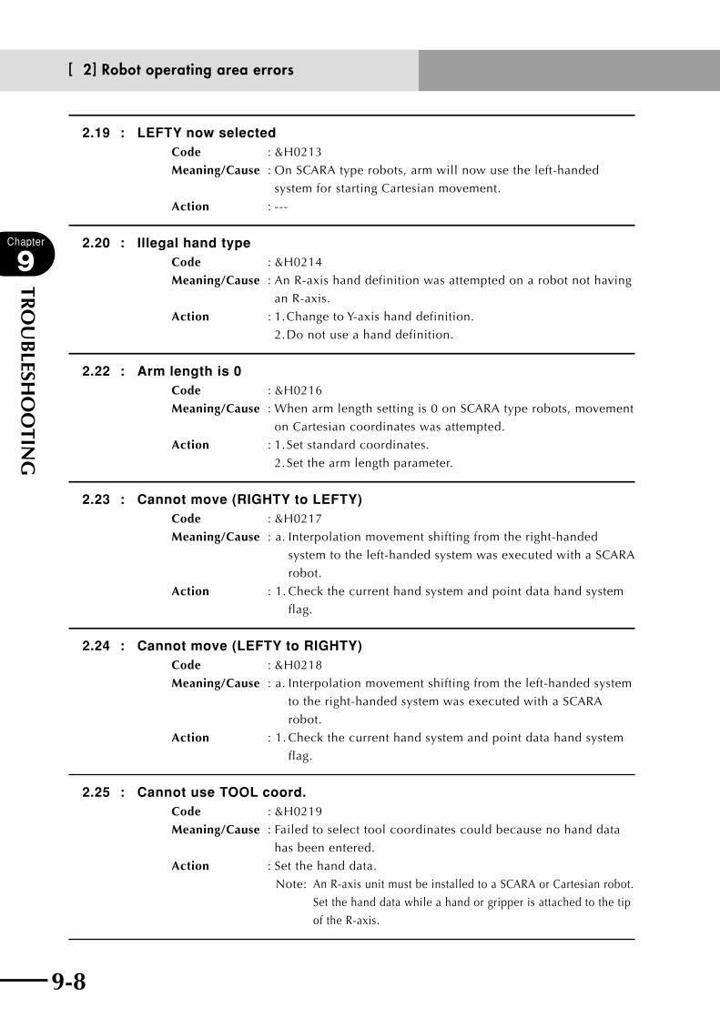
9-8
Chapter
9
TRO
UB
LESHO
OTIN
G
9-9
2.19 : LEFTY now selectedCode : &H0213
Meaning/Cause : On SCARA type robots, arm will now use the left-handed
system for starting Cartesian movement.
Action : ---
2.20 : Illegal hand typeCode : &H0214
Meaning/Cause : An R-axis hand definition was attempted on a robot not having
an R-axis.
Action : 1. Change to Y-axis hand definition.
2. Do not use a hand definition.
2.22 : Arm length is 0Code : &H0216
Meaning/Cause : When arm length setting is 0 on SCARA type robots, movement
on Cartesian coordinates was attempted.
Action : 1. Set standard coordinates.
2. Set the arm length parameter.
2.23 : Cannot move (RIGHTY to LEFTY)Code : &H0217
Meaning/Cause : a. Interpolation movement shifting from the right-handed
system to the left-handed system was executed with a SCARA
robot.
Action : 1. Check the current hand system and point data hand system
flag.
2.24 : Cannot move (LEFTY to RIGHTY)Code : &H0218
Meaning/Cause : a. Interpolation movement shifting from the left-handed system
to the right-handed system was executed with a SCARA
robot.
Action : 1. Check the current hand system and point data hand system
flag.
2.25 : Cannot use TOOL coord.Code : &H0219
Meaning/Cause : Failed to select tool coordinates could because no hand data
has been entered.
Action : Set the hand data.
Note: An R-axis unit must be installed to a SCARA or Cartesian robot.
Set the hand data while a hand or gripper is attached to the tip
of the R-axis.
[ 2] Robot operating area errors

9-8 9-9
Chapter
9
TRO
UB
LESHO
OTIN
G
2.26 : Collision in W. carrierCode : &H021A
Meaning/Cause : Failed to move the double-carrier axis, because one carrier will
interfere with the other carrier.
Action : If this error occurred during MANUAL mode:
1. Move the other carrier to a position where the two carriers
will not interfere with each other and then move the robot
manually.
If this error occurred during AUTO mode:
1. Change the target position of one carrier so it will not
interfere with the other carrier.
2. Move the other carrier to a position where it will not
interfere with the first carrier’s target position, and then
move that first carrier.
3. Set the double-carrier parameter control mode to "Off" or "On".
When set to "Off", this error does not occur, but the anti-
collision function for double-carriers will not work so the
carriers might collide with each other.
When set to "On", one carrier starts moving after
waiting until the other carrier moves to a position
where no interference occurs.
2.27 : W. carrier deadlockCode : &H021B
Meaning/Cause : Failed to move the double-carrier axis and a deadlock
occurred, because the target positions of both carriers will
interfere with each other.
Action : Check the robot program.
[ 3] Program file operating errors
3.1 : Too many programsCode : &H0301
Meaning/Cause : Making of a new program was attempted after number of
programs exceeded 100.
Action : Make a new program after deleting an unnecessary program.
(Make a backup if necessary.)
[ 3] Program file operating errors
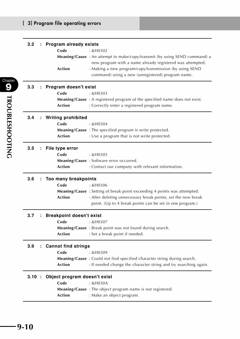
9-10
Chapter
9
TRO
UB
LESHO
OTIN
G
9-11
3.2 : Program already existsCode : &H0302
Meaning/Cause : An attempt to make/copy/transmit (by using SEND command) a
new program with a name already registered was attempted.
Action : Making a new program/copy/transmission (by using SEND
command) using a new (unregistered) program name.
3.3 : Program doesn't existCode : &H0303
Meaning/Cause : A registered program of the specified name does not exist.
Action : Correctly enter a registered program name.
3.4 : Writing prohibitedCode : &H0304
Meaning/Cause : The specified program is write protected.
Action : Use a program that is not write protected.
3.5 : File type errorCode : &H0305
Meaning/Cause : Software error occurred.
Action : Contact our company with relevant information.
3.6 : Too many breakpointsCode : &H0306
Meaning/Cause : Setting of break point exceeding 4 points was attempted.
Action : After deleting unnecessary break points, set the new break
point. (Up to 4 break points can be set in one program.)
3.7 : Breakpoint doesn't existCode : &H0307
Meaning/Cause : Break point was not found during search.
Action : Set a break point if needed.
3.9 : Cannot find stringsCode : &H0309
Meaning/Cause : Could not find specified character string during search.
Action : If needed change the character string and try searching again.
3.10 : Object program doesn't existCode : &H030A
Meaning/Cause : The object program name is not registered.
Action : Make an object program.
[ 3] Program file operating errors
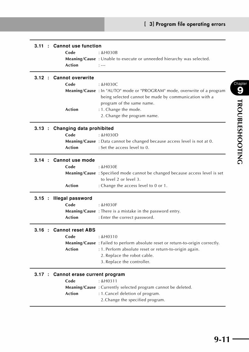
9-10 9-11
Chapter
9
TRO
UB
LESHO
OTIN
G
3.11 : Cannot use functionCode : &H030B
Meaning/Cause : Unable to execute or unneeded hierarchy was selected.
Action : ---
3.12 : Cannot overwriteCode : &H030C
Meaning/Cause : In "AUTO" mode or "PROGRAM" mode, overwrite of a program
being selected cannot be made by communication with a
program of the same name.
Action : 1. Change the mode.
2. Change the program name.
3.13 : Changing data prohibitedCode : &H030D
Meaning/Cause : Data cannot be changed because access level is not at 0.
Action : Set the access level to 0.
3.14 : Cannot use modeCode : &H030E
Meaning/Cause : Specified mode cannot be changed because access level is set
to level 2 or level 3.
Action : Change the access level to 0 or 1.
3.15 : Illegal passwordCode : &H030F
Meaning/Cause : There is a mistake in the password entry.
Action : Enter the correct password.
3.16 : Cannot reset ABSCode : &H0310
Meaning/Cause : Failed to perform absolute reset or return-to-origin correctly.
Action : 1. Perform absolute reset or return-to-origin again.
2. Replace the robot cable.
3. Replace the controller.
3.17 : Cannot erase current programCode : &H0311
Meaning/Cause : Currently selected program cannot be deleted.
Action : 1. Cancel deletion of program.
2. Change the specified program.
[ 3] Program file operating errors

9-12
Chapter
9
TRO
UB
LESHO
OTIN
G
9-13
3.18 : Duplicated BreakpointCode : &H0312
Meaning/Cause : Setting of breakpoint was attempted on line already set with
breakpoints.
Action : To set the breakpoint, specify a line where breakpoints have
not yet been set.
[ 4] Data entry and edit errors
4.1 : Point number errorCode : &H0401
Meaning/Cause : A point number was entered exceeding P9999.
Action : Input a correct point number.
4.2 : Input format errorCode : &H0402
Meaning/Cause : Wrong format was used to enter the data.
Action : Use the correct data format.
4.3 : Undefined palletCode : &H0403
Meaning/Cause : Specified pallet is undefined.
Action : 1. Change the specified pallet.
2. Define the pallet.
4.4 : Undefined robot numberCode : &H0404
Meaning/Cause : Specified robot number does not exist.
Action : Enter a correct robot number.
4.5 : Undefined axis numberCode : &H0405
Meaning/Cause : Specified axis number does not exist.
Action : Enter a correct axis number.
[ 5] Robot language syntax (compiling) errors
5.1 : Syntax errorCode : &H0501
Meaning/Cause : Syntax error found in program.
Action : Change to the correct syntax.
[ 4] Data entry and edit errors
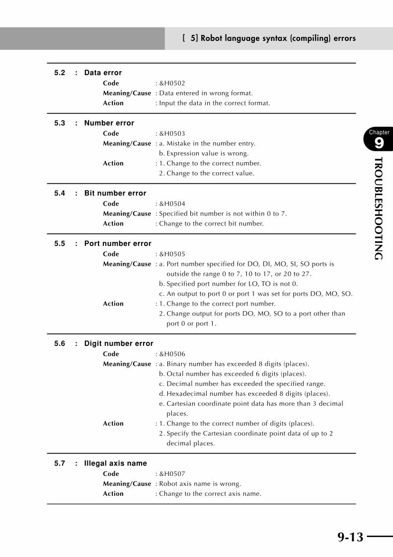
9-12 9-13
Chapter
9
TRO
UB
LESHO
OTIN
G
5.2 : Data errorCode : &H0502
Meaning/Cause : Data entered in wrong format.
Action : Input the data in the correct format.
5.3 : Number errorCode : &H0503
Meaning/Cause : a. Mistake in the number entry.
b. Expression value is wrong.
Action : 1. Change to the correct number.
2. Change to the correct value.
5.4 : Bit number errorCode : &H0504
Meaning/Cause : Specified bit number is not within 0 to 7.
Action : Change to the correct bit number.
5.5 : Port number errorCode : &H0505
Meaning/Cause : a. Port number specified for DO, DI, MO, SI, SO ports is
outside the range 0 to 7, 10 to 17, or 20 to 27.
b. Specified port number for LO, TO is not 0.
c. An output to port 0 or port 1 was set for ports DO, MO, SO.
Action : 1. Change to the correct port number.
2. Change output for ports DO, MO, SO to a port other than
port 0 or port 1.
5.6 : Digit number errorCode : &H0506
Meaning/Cause : a. Binary number has exceeded 8 digits (places).
b. Octal number has exceeded 6 digits (places).
c. Decimal number has exceeded the specified range.
d. Hexadecimal number has exceeded 8 digits (places).
e. Cartesian coordinate point data has more than 3 decimal
places.
Action : 1. Change to the correct number of digits (places).
2. Specify the Cartesian coordinate point data of up to 2
decimal places.
5.7 : Illegal axis nameCode : &H0507
Meaning/Cause : Robot axis name is wrong.
Action : Change to the correct axis name.
[ 5] Robot language syntax (compiling) errors
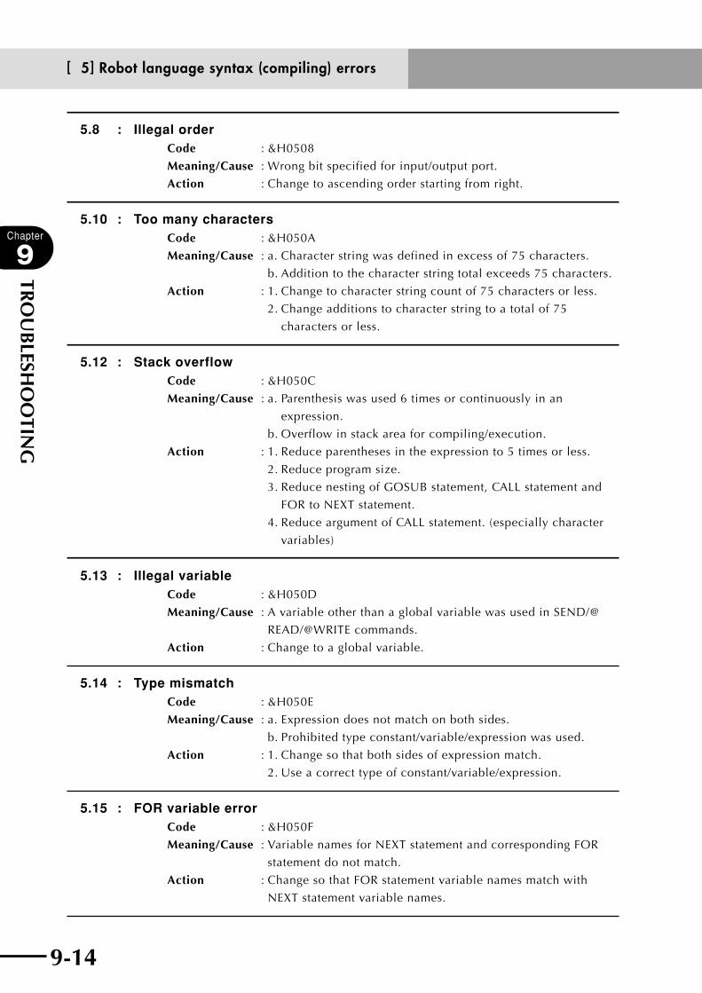
9-14
Chapter
9
TRO
UB
LESHO
OTIN
G
9-15
5.8 : Illegal orderCode : &H0508
Meaning/Cause : Wrong bit specified for input/output port.
Action : Change to ascending order starting from right.
5.10 : Too many charactersCode : &H050A
Meaning/Cause : a. Character string was defined in excess of 75 characters.
b. Addition to the character string total exceeds 75 characters.
Action : 1. Change to character string count of 75 characters or less.
2. Change additions to character string to a total of 75
characters or less.
5.12 : Stack overflowCode : &H050C
Meaning/Cause : a. Parenthesis was used 6 times or continuously in an
expression.
b. Overflow in stack area for compiling/execution.
Action : 1. Reduce parentheses in the expression to 5 times or less.
2. Reduce program size.
3. Reduce nesting of GOSUB statement, CALL statement and
FOR to NEXT statement.
4. Reduce argument of CALL statement. (especially character
variables)
5.13 : Illegal variableCode : &H050D
Meaning/Cause : A variable other than a global variable was used in SEND/@
READ/@WRITE commands.
Action : Change to a global variable.
5.14 : Type mismatchCode : &H050E
Meaning/Cause : a. Expression does not match on both sides.
b. Prohibited type constant/variable/expression was used.
Action : 1. Change so that both sides of expression match.
2. Use a correct type of constant/variable/expression.
5.15 : FOR variable errorCode : &H050F
Meaning/Cause : Variable names for NEXT statement and corresponding FOR
statement do not match.
Action : Change so that FOR statement variable names match with
NEXT statement variable names.
[ 5] Robot language syntax (compiling) errors

9-14 9-15
Chapter
9
TRO
UB
LESHO
OTIN
G
5.16 : WEND without WHILECode : &H0510
Meaning/Cause : There is no WHILE statement corresponding to the WEND
statement.
Action : 1. Delete the WEND statement.
2. Add a WHILE statement corresponding to the WEND
statement.
5.17 : WHILE without WENDCode : &H0511
Meaning/Cause : There is no WEND statement corresponding to WHILE
statement.
Action : 1. Delete the WHILE statement.
2. Add a WEND statement corresponding to the WHILE
statement.
5.18 : NEXT without FORCode : &H0512
Meaning/Cause : a. There is no FOR statement corresponding to NEXT statement.
b. NEXT command was executed without executing FOR
command.
Action : 1. Delete the NEXT statement.
2. Add a FOR statement corresponding to the NEXT statement.
3. Confirm execution of FOR command.
5.19 : FOR without NEXTCode : &H0513
Meaning/Cause : There is no NEXT statement corresponding to FOR statement.
Action : 1. Delete the FOR statement.
2. Add a NEXT statement corresponding to the FOR statement.
5.20 : ENDIF without IFCode : &H0514
Meaning/Cause : There is no IF statement corresponding to ENDIF statement.
Action : 1. Delete the ENDIF statement.
2. Add an IF statement corresponding to the ENDIF statement.
5.21 : ELSE without IFCode : &H0515
Meaning/Cause : There is no IF statement corresponding to ELSE statement.
Action : 1. Delete the ELSE statement.
2. Add an IF statement corresponding to the ELSE statement.
[ 5] Robot language syntax (compiling) errors

9-16
Chapter
9
TRO
UB
LESHO
OTIN
G
9-17
5.22 : IF without ENDIFCode : &H0516
Meaning/Cause : There is no ENDIF statement corresponding to IF statement.
Action : 1. Delete the IF statement.
2. Add an ENDIF statement corresponding to the IF statement.
5.23 : ELSE without ENDIFCode : &H0517
Meaning/Cause : There is no ENDIF statement corresponding to ELSE statement.
Action : 1. Delete the ELSE statement.
2. Add an ENDIF statement corresponding to the ELSE
statement.
5.24 : END SUB without SUBCode : &H0518
Meaning/Cause : a. There is no SUB statement corresponding to END SUB
statement.
b. END SUB command was executed without SUB command.
Action : 1. Delete the END SUB statement.
2. Add a SUB statement corresponding to the END SUB
statement.
3. Confirm execution of SUB command.
5.25 : SUB without END SUBCode : &H0519
Meaning/Cause : There is no END SUB statement corresponding to SUB
statement.
Action : 1. Delete the SUB statement.
2. Add an END SUB statement corresponding to the SUB
statement.
5.26 : Duplicated variableCode : &H051A
Meaning/Cause : Two or more array variables were defined for the same name.
Action : Delete a definition statement for the array variables with the
same name.
5.27 : Duplicated identifierCode : &H051B
Meaning/Cause : Two or more identifiers were defined for the same name.
Action : Define another identifier.
[ 5] Robot language syntax (compiling) errors
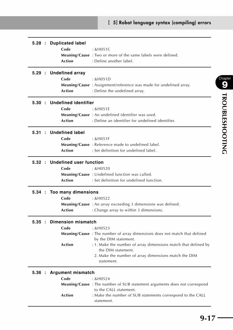
9-16 9-17
Chapter
9
TRO
UB
LESHO
OTIN
G
5.28 : Duplicated labelCode : &H051C
Meaning/Cause : Two or more of the same labels were defined.
Action : Define another label.
5.29 : Undefined arrayCode : &H051D
Meaning/Cause : Assignment/reference was made for undefined array.
Action : Define the undefined array.
5.30 : Undefined identifierCode : &H051E
Meaning/Cause : An undefined identifier was used.
Action : Define an identifier for undefined identifier.
5.31 : Undefined labelCode : &H051F
Meaning/Cause : Reference made to undefined label.
Action : Set definition for undefined label.
5.32 : Undefined user functionCode : &H0520
Meaning/Cause : Undefined function was called.
Action : Set definition for undefined function.
5.34 : Too many dimensionsCode : &H0522
Meaning/Cause : An array exceeding 3 dimensions was defined.
Action : Change array to within 3 dimensions.
5.35 : Dimension mismatchCode : &H0523Meaning/Cause : The number of array dimensions does not match that defined
by the DIM statement.Action : 1. Make the number of array dimensions match that defined by
the DIM statement. 2. Make the number of array dimensions match the DIM
statement.
5.36 : Argument mismatchCode : &H0524Meaning/Cause : The number of SUB statement arguments does not correspond
to the CALL statement.Action : Make the number of SUB statements correspond to the CALL
statement.
[ 5] Robot language syntax (compiling) errors
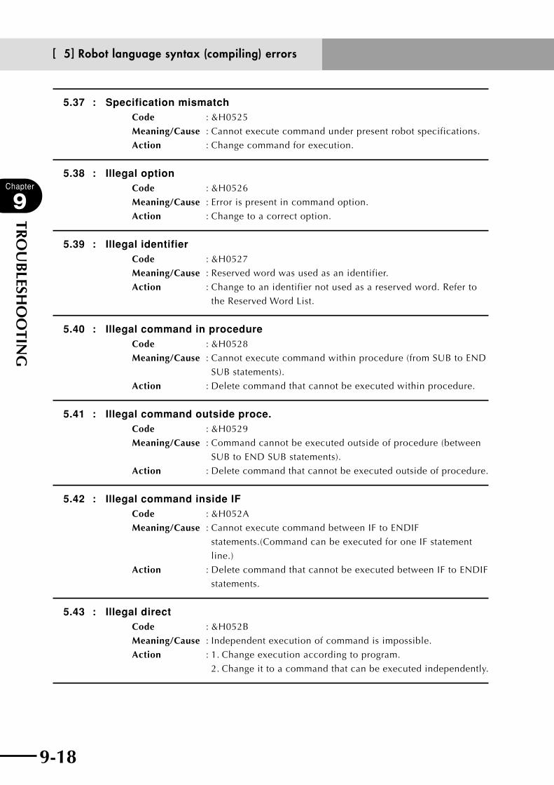
9-18
Chapter
9
TRO
UB
LESHO
OTIN
G
9-19
5.37 : Specification mismatchCode : &H0525
Meaning/Cause : Cannot execute command under present robot specifications.
Action : Change command for execution.
5.38 : Illegal optionCode : &H0526
Meaning/Cause : Error is present in command option.
Action : Change to a correct option.
5.39 : Illegal identifierCode : &H0527
Meaning/Cause : Reserved word was used as an identifier.
Action : Change to an identifier not used as a reserved word. Refer to
the Reserved Word List.
5.40 : Illegal command in procedureCode : &H0528
Meaning/Cause : Cannot execute command within procedure (from SUB to END
SUB statements).
Action : Delete command that cannot be executed within procedure.
5.41 : Illegal command outside proce.Code : &H0529
Meaning/Cause : Command cannot be executed outside of procedure (between
SUB to END SUB statements).
Action : Delete command that cannot be executed outside of procedure.
5.42 : Illegal command inside IFCode : &H052A
Meaning/Cause : Cannot execute command between IF to ENDIF
statements.(Command can be executed for one IF statement
line.)
Action : Delete command that cannot be executed between IF to ENDIF
statements.
5.43 : Illegal directCode : &H052B
Meaning/Cause : Independent execution of command is impossible.
Action : 1. Change execution according to program.
2. Change it to a command that can be executed independently.
[ 5] Robot language syntax (compiling) errors
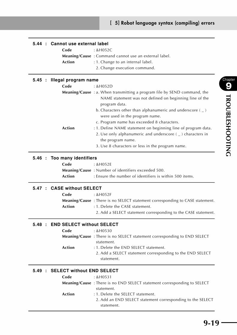
9-18 9-19
Chapter
9
TRO
UB
LESHO
OTIN
G
5.44 : Cannot use external labelCode : &H052C
Meaning/Cause : Command cannot use an external label.
Action : 1. Change to an internal label.
2. Change execution command.
5.45 : Illegal program nameCode : &H052D
Meaning/Cause : a. When transmitting a program file by SEND command, the
NAME statement was not defined on beginning line of the
program data.
b. Characters other than alphanumeric and underscore ( _ )
were used in the program name.
c. Program name has exceeded 8 characters.
Action : 1. Define NAME statement on beginning line of program data.
2. Use only alphanumeric and underscore ( _ ) characters in
the program name.
3. Use 8 characters or less in the program name.
5.46 : Too many identifiersCode : &H052E
Meaning/Cause : Number of identifiers exceeded 500.
Action : Ensure the number of identifiers is within 500 items.
5.47 : CASE without SELECTCode : &H052F
Meaning/Cause : There is no SELECT statement corresponding to CASE statement.
Action : 1. Delete the CASE statement.
2. Add a SELECT statement corresponding to the CASE statement.
5.48 : END SELECT without SELECTCode : &H0530Meaning/Cause : There is no SELECT statement corresponding to END SELECT
statement.Action : 1. Delete the END SELECT statement. 2. Add a SELECT statement corresponding to the END SELECT
statement.
5.49 : SELECT without END SELECTCode : &H0531
Meaning/Cause : There is no END SELECT statement corresponding to SELECT statement.
Action : 1. Delete the SELECT statement. 2. Add an END SELECT statement corresponding to the SELECT
statement.
[ 5] Robot language syntax (compiling) errors

9-20
Chapter
9
TRO
UB
LESHO
OTIN
G
9-21
5.50 : CASE without END SELECTCode : &H0532
Meaning/Cause : There is no END SELECT statement corresponding to CASE
statement.
Action : 1. Delete the CASE statement.
2. Add an END SELECT statement corresponding to the CASE
statement.
5.51 : Illegal command lineCode : &H0533
Meaning/Cause : Cannot execute command statement between SELECT and
CASE statements.
Action : Delete the command statement between SELECT and CASE
statements.
5.52 : Command doesn't existCode : &H0534
Meaning/Cause : Line does not have a command statement.
Action : 1. Add a command statement.
2. Delete the line that does not have a command statement.
5.53 : Compile failureCode : &H0535
Meaning/Cause : Error occurred in software
Action : Report details of error to our company.
5.54 : ELSEIF without IFCode : &H0536
Meaning/Cause : There is no IF statement corresponding to ELSEIF statement.
Action : 1. Delete the ELSEIF statement.
2. Add an IF statement corresponding to the ELSEIF statement.
5.55 : ELSEIF without ENDIFCode : &H0537
Meaning/Cause : There is no ENDIF statement corresponding to ELSEIF
statement.
Action : 1. Delete the ELSEIF statement.
2. Add an ENDIF statement corresponding to the ELSEIF
statement.
[ 5] Robot language syntax (compiling) errors

9-20 9-21
Chapter
9
TRO
UB
LESHO
OTIN
G
[ 6] Robot language execution errors
6.1 : Illegal commandCode : &H0601
Meaning/Cause : Execution of a non-supported or non-executable command was
attempted.
Action : Change to a command that can be executed.
6.2 : Illegal function callCode : &H0602
Meaning/Cause : The expression "ON <expression> GOTO"/"ON <expression>
GOSUB" command was a negative value.
Action : Change <expression> to a positive value.
6.3 : Division by 0Code : &H0603
Meaning/Cause : A command to divide by 0 (÷ 0) was attempted.
Action : Change from the divide by 0 command.
6.4 : Point doesn't existCode : &H0604
Meaning/Cause : Assignment/movement/reference to an undefined point was
attempted.
Action : Define the point.
6.5 : Coordinate type errorCode : &H0605
Meaning/Cause : a. Arithmetic operations of joint coordinate point data and
Cartesian coordinate point data were attempted.
b. Joint coordinate system and Cartesian coordinate system
were mixed together within the MOVE C, command point
data.
c. Point data in PMOVE command was not specified in
Cartesian coordinates.
Action : 1. Change to same coordinate system.
2. Change to Cartesian coordinate system.
6.6 : Subscript out of rangeCode : &H0606
Meaning/Cause : A subscript of an array variable has exceeded the range defined
in DIM statement.
Action : Change the subscript of array variable to within the defined
range.
[ 6] Robot language execution errors
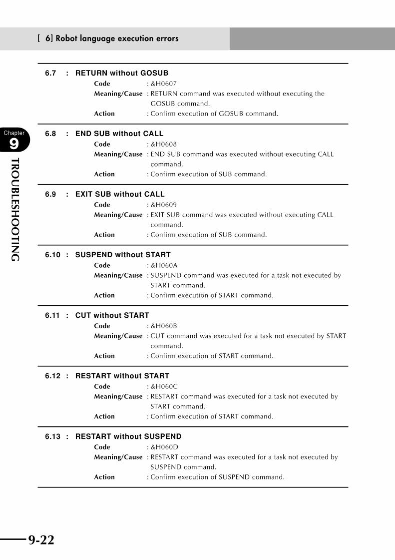
9-22
Chapter
9
TRO
UB
LESHO
OTIN
G
9-23
6.7 : RETURN without GOSUBCode : &H0607
Meaning/Cause : RETURN command was executed without executing the
GOSUB command.
Action : Confirm execution of GOSUB command.
6.8 : END SUB without CALLCode : &H0608
Meaning/Cause : END SUB command was executed without executing CALL
command.
Action : Confirm execution of SUB command.
6.9 : EXIT SUB without CALLCode : &H0609
Meaning/Cause : EXIT SUB command was executed without executing CALL
command.
Action : Confirm execution of SUB command.
6.10 : SUSPEND without STARTCode : &H060A
Meaning/Cause : SUSPEND command was executed for a task not executed by
START command.
Action : Confirm execution of START command.
6.11 : CUT without STARTCode : &H060B
Meaning/Cause : CUT command was executed for a task not executed by START
command.
Action : Confirm execution of START command.
6.12 : RESTART without STARTCode : &H060C
Meaning/Cause : RESTART command was executed for a task not executed by
START command.
Action : Confirm execution of START command.
6.13 : RESTART without SUSPENDCode : &H060D
Meaning/Cause : RESTART command was executed for a task not executed by
SUSPEND command.
Action : Confirm execution of SUSPEND command.
[ 6] Robot language execution errors
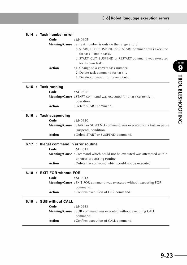
9-22 9-23
Chapter
9
TRO
UB
LESHO
OTIN
G
6.14 : Task number errorCode : &H060E
Meaning/Cause : a. Task number is outside the range 2 to 8.
b. START, CUT, SUSPEND or RESTART command was executed
for task 1 (main task).
c. START, CUT, SUSPEND or RESTART command was executed
for its own task.
Action : 1. Change to a correct task number.
2. Delete task command for task 1.
3. Delete command for its own task.
6.15 : Task runningCode : &H060F
Meaning/Cause : START command was executed for a task currently in
operation.
Action : Delete START command.
6.16 : Task suspendingCode : &H0610
Meaning/Cause : START or SUSPEND command was executed for a task in pause
(suspend) condition.
Action : Delete START or SUSPEND command.
6.17 : Illegal command in error routineCode : &H0611
Meaning/Cause : Command which could not be executed was attempted within
an error processing routine.
Action : Delete the command which could not be executed.
6.18 : EXIT FOR without FORCode : &H0612
Meaning/Cause : EXIT FOR command was executed without executing FOR
command.
Action : Confirm execution of FOR command.
6.19 : SUB without CALLCode : &H0613
Meaning/Cause : SUB command was executed without executing CALL
command.
Action : Confirm execution of CALL command.
[ 6] Robot language execution errors

9-24
Chapter
9
TRO
UB
LESHO
OTIN
G
9-25
6.20 : Not execute CALLCode : &H0614
Meaning/Cause : CALL command was not executed.
Action : Confirm execution of CALL command.
6.21 : Same point existsCode : &H0615
Meaning/Cause : a. Same points exist for 1 of 3 points of an MOVE C command.
b. Same points are consecutively on the path of PATH motion.
Action : 1. Change the MOVE C command to 3 different points.
2. Make changes so that the same points are not consecutively
on the path of PATH motion
6.22 : 3 points on lineCode : &H0616
Meaning/Cause : Three points of an MOVE C command were placed on a
straight line.
Action : Change the 3 different points of the MOVE C command so they
are not on the same straight line.
6.23 : Circular arc radius too smallCode : &H0617
Meaning/Cause : MOVE C command radius is less than 1mm.
Action : Change MOVE C command to 1mm or more for circular arc radius.
6.24 : Circular arc radius too largeCode : &H0618
Meaning/Cause : MOVE C command radius exceeded 5000mm (5 meters).
Action : Change MOVE C command to within 5000mm (5 meters) for
circular arc radius.
6.25 : Too low speedCode : &H0619
Meaning/Cause : Specified speed was too low so movement time exceeded
300 seconds. Maximum movement time is 300 seconds.
Action : Increase the specified speed.
6.26 : No sufficient memory for OUTCode : &H061A
Meaning/Cause : Failed to run an OUT command due to insufficient memory
caused by multiple OUT commands that were run in
succession.
Action : Check the number of OUT commands. The maximum number
of OUT commands that can be run in parallel is 16.
[ 6] Robot language execution errors
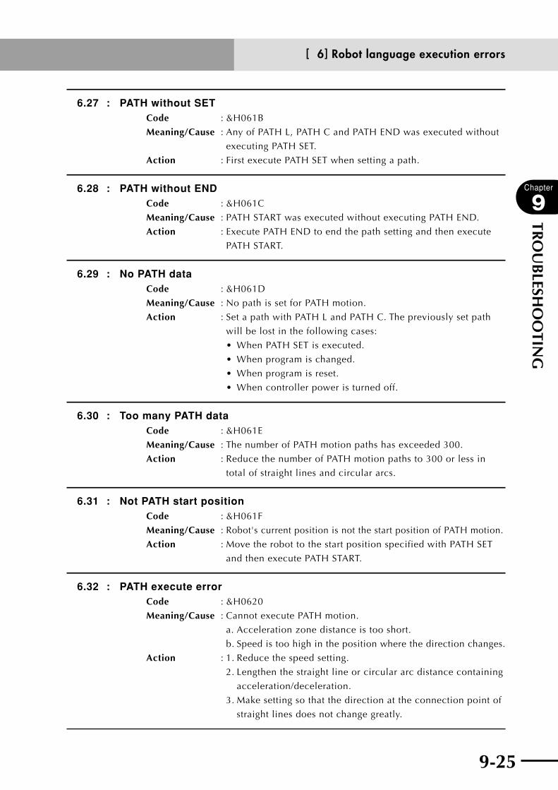
9-24 9-25
Chapter
9
TRO
UB
LESHO
OTIN
G
6.27 : PATH without SETCode : &H061B
Meaning/Cause : Any of PATH L, PATH C and PATH END was executed without
executing PATH SET.
Action : First execute PATH SET when setting a path.
6.28 : PATH without ENDCode : &H061C
Meaning/Cause : PATH START was executed without executing PATH END.
Action : Execute PATH END to end the path setting and then execute
PATH START.
6.29 : No PATH dataCode : &H061D
Meaning/Cause : No path is set for PATH motion.
Action : Set a path with PATH L and PATH C. The previously set path
will be lost in the following cases:
• WhenPATHSETisexecuted.
• Whenprogramischanged.
• Whenprogramisreset.
• Whencontrollerpoweristurnedoff.
6.30 : Too many PATH dataCode : &H061E
Meaning/Cause : The number of PATH motion paths has exceeded 300.
Action : Reduce the number of PATH motion paths to 300 or less in
total of straight lines and circular arcs.
6.31 : Not PATH start positionCode : &H061F
Meaning/Cause : Robot's current position is not the start position of PATH motion.
Action : Move the robot to the start position specified with PATH SET
and then execute PATH START.
6.32 : PATH execute errorCode : &H0620
Meaning/Cause : Cannot execute PATH motion.
a. Acceleration zone distance is too short.
b. Speed is too high in the position where the direction changes.
Action : 1. Reduce the speed setting.
2. Lengthen the straight line or circular arc distance containing
acceleration/deceleration.
3. Make setting so that the direction at the connection point of
straight lines does not change greatly.
[ 6] Robot language execution errors
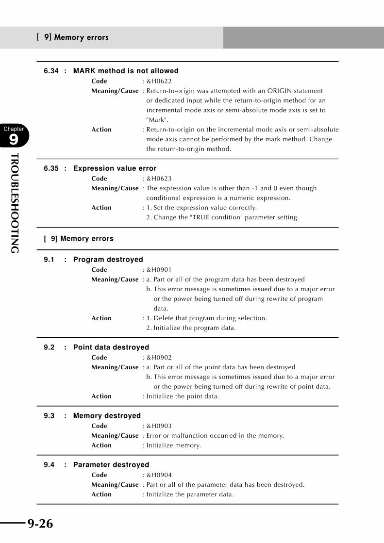
9-26
Chapter
9
TRO
UB
LESHO
OTIN
G
9-27
6.34 : MARK method is not allowedCode : &H0622
Meaning/Cause : Return-to-origin was attempted with an ORIGIN statement
or dedicated input while the return-to-origin method for an
incremental mode axis or semi-absolute mode axis is set to
"Mark".
Action : Return-to-origin on the incremental mode axis or semi-absolute
mode axis cannot be performed by the mark method. Change
the return-to-origin method.
6.35 : Expression value errorCode : &H0623
Meaning/Cause : The expression value is other than -1 and 0 even though
conditional expression is a numeric expression.
Action : 1. Set the expression value correctly.
2. Change the "TRUE condition" parameter setting.
[ 9] Memory errors
9.1 : Program destroyedCode : &H0901
Meaning/Cause : a. Part or all of the program data has been destroyed
b. This error message is sometimes issued due to a major error
or the power being turned off during rewrite of program
data.
Action : 1. Delete that program during selection.
2. Initialize the program data.
9.2 : Point data destroyedCode : &H0902
Meaning/Cause : a. Part or all of the point data has been destroyed
b. This error message is sometimes issued due to a major error
or the power being turned off during rewrite of point data.
Action : Initialize the point data.
9.3 : Memory destroyedCode : &H0903
Meaning/Cause : Error or malfunction occurred in the memory.
Action : Initialize memory.
9.4 : Parameter destroyedCode : &H0904
Meaning/Cause : Part or all of the parameter data has been destroyed.
Action : Initialize the parameter data.
[ 9] Memory errors
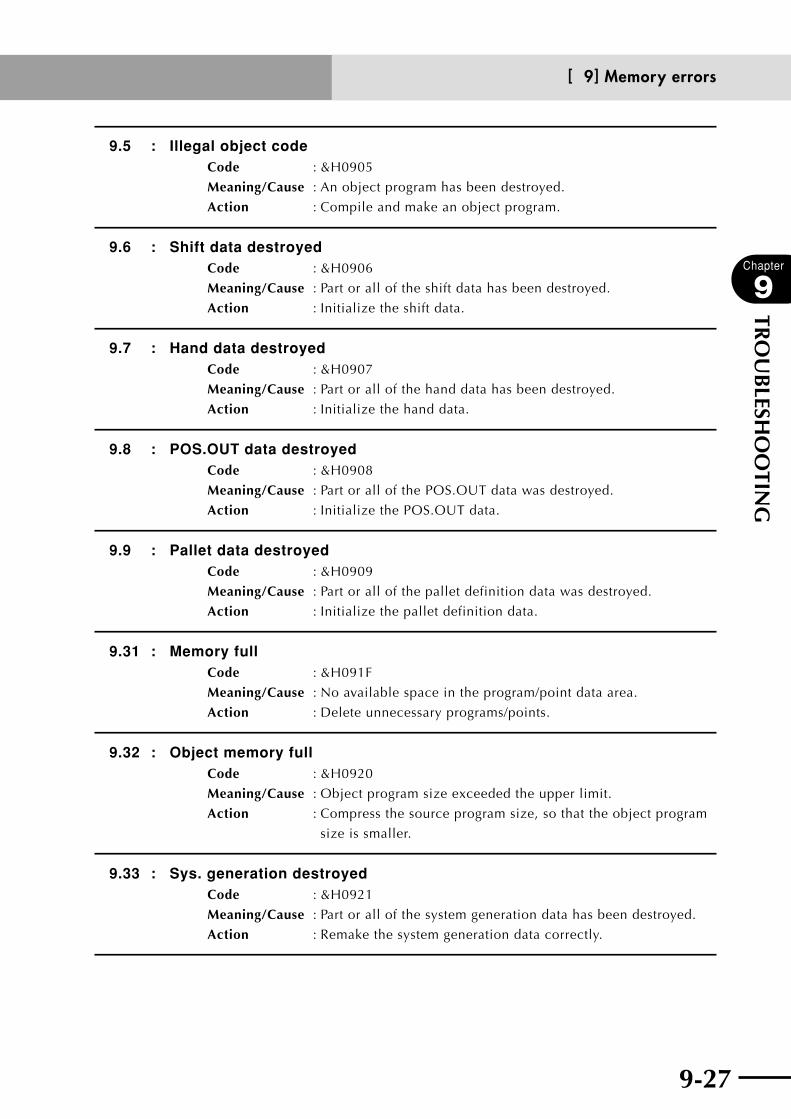
9-26 9-27
Chapter
9
TRO
UB
LESHO
OTIN
G
9.5 : Illegal object codeCode : &H0905
Meaning/Cause : An object program has been destroyed.
Action : Compile and make an object program.
9.6 : Shift data destroyedCode : &H0906
Meaning/Cause : Part or all of the shift data has been destroyed.
Action : Initialize the shift data.
9.7 : Hand data destroyedCode : &H0907
Meaning/Cause : Part or all of the hand data has been destroyed.
Action : Initialize the hand data.
9.8 : POS.OUT data destroyedCode : &H0908
Meaning/Cause : Part or all of the POS.OUT data was destroyed.
Action : Initialize the POS.OUT data.
9.9 : Pallet data destroyedCode : &H0909
Meaning/Cause : Part or all of the pallet definition data was destroyed.
Action : Initialize the pallet definition data.
9.31 : Memory fullCode : &H091F
Meaning/Cause : No available space in the program/point data area.
Action : Delete unnecessary programs/points.
9.32 : Object memory fullCode : &H0920
Meaning/Cause : Object program size exceeded the upper limit.
Action : Compress the source program size, so that the object program
size is smaller.
9.33 : Sys. generation destroyedCode : &H0921
Meaning/Cause : Part or all of the system generation data has been destroyed.
Action : Remake the system generation data correctly.
[ 9] Memory errors
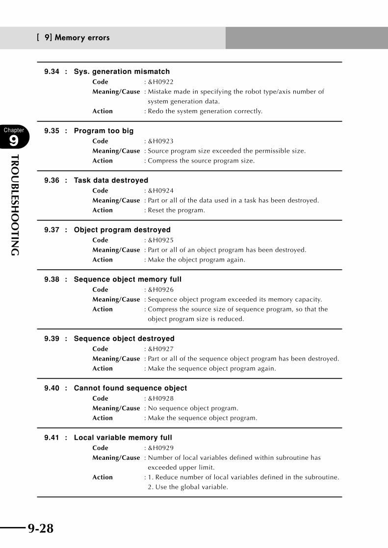
9-28
Chapter
9
TRO
UB
LESHO
OTIN
G
9-29
9.34 : Sys. generation mismatchCode : &H0922
Meaning/Cause : Mistake made in specifying the robot type/axis number of
system generation data.
Action : Redo the system generation correctly.
9.35 : Program too bigCode : &H0923
Meaning/Cause : Source program size exceeded the permissible size.
Action : Compress the source program size.
9.36 : Task data destroyedCode : &H0924
Meaning/Cause : Part or all of the data used in a task has been destroyed.
Action : Reset the program.
9.37 : Object program destroyedCode : &H0925
Meaning/Cause : Part or all of an object program has been destroyed.
Action : Make the object program again.
9.38 : Sequence object memory fullCode : &H0926
Meaning/Cause : Sequence object program exceeded its memory capacity.
Action : Compress the source size of sequence program, so that the
object program size is reduced.
9.39 : Sequence object destroyedCode : &H0927
Meaning/Cause : Part or all of the sequence object program has been destroyed.
Action : Make the sequence object program again.
9.40 : Cannot found sequence objectCode : &H0928
Meaning/Cause : No sequence object program.
Action : Make the sequence object program.
9.41 : Local variable memory fullCode : &H0929
Meaning/Cause : Number of local variables defined within subroutine has
exceeded upper limit.
Action : 1. Reduce number of local variables defined in the subroutine.
2. Use the global variable.
[ 9] Memory errors

9-28 9-29
Chapter
9
TRO
UB
LESHO
OTIN
G
[10] System setting or hardware errors
10.1 : Robot disconnectedCode : &H0A01
Meaning/Cause : Axis control was attempted with "no axis" specified for all axes
of system generation.
Action : Re-perform the system generation.
10.3 : D.unit disconnectedCode : &H0A03
Meaning/Cause : Manual movement was attempted on the axis that is not
specified.
Action : Do not perform any axis-related operation.
10.6 : DRIVER.unit version mismatchCode : &H0A06
Meaning/Cause : Driver unit version does not match the CPU unit.
Action : Make sure the CPU unit and driver unit versions match each
other.
10.7 : CPU.unit version mismatchCode : &H0A07
Meaning/Cause : CPU unit version does not match the CPU.
Action : Make sure the CPU unit and driver unit versions match each
other.
10.8 : Cannot set auxiliary axisCode : &H0A08
Meaning/Cause : Setting of axis that cannot be set as an auxiliary axis was
attempted.
The following axes cannot be set as an auxiliary axis.
• SCARAtyperobotaxes
• XandYaxesexceptonMULTItyperobots
Action : 1. Do not set an auxiliary axis.
2. Change the axis setting.
10.9 : Cannot set no axisCode : &H0A09
Meaning/Cause : A no-axis setting was attempted on an axis which cannot
accept it.
The following axes cannot be set to no-axis.
• XandYaxesexceptonMULTItyperobots
Action : 1. Do not make a no-axis setting.
2. Change the axis setting.
[10] System setting or hardware errors

9-30
Chapter
9
TRO
UB
LESHO
OTIN
G
9-31
10.10 : Cannot change axisCode : &H0A0A
Meaning/Cause : Changing of an axis whose setting cannot be changed was
attempted.
The following axes cannot be changed.
• XandYaxesonSCARAtyperobots
Action : 1. Do not change that axis.
2. Change a different axis.
10.13 : Cannot set DualdriveCode : &H0A0D
Meaning/Cause : A dual drive setting was attempted on an axis that cannot be
set to dual drive.
Action : 1. Do not set to dual drive.
2. Change the axis setting.
10.14: Undefined parameter foundCode : &H0A0E
Meaning/Cause : a. Undefined, wrong parameter data was written because
controller data from different controller version was used.
b. Parameter name is wrong.
Action : 1. Write the correct parameter data.
2. Enter the parameter name correctly.
3. Set the "Skip undefined parameters" parameter to "VALID".
10.21 : Sys. backup battery low voltageCode : &H0A15
Meaning/Cause : a. System backup battery voltage is low.
b. System backup battery is disconnected from CPU board.
Action : 1. Replace system backup battery.
2. Connect system backup battery securely to CPU board.
Dedicated output : DO15 (Battery alarm output) turns on when the battery voltage is low.
[10] System setting or hardware errors

9-30 9-31
Chapter
9
TRO
UB
LESHO
OTIN
G
[12] I/O and option board errors
12.1 : Emg.stop onCode : &H0C01
Meaning/Cause : a. Emergency stop button was pressed.
b. Emergency stop terminals on SAFETY connector are open
(emergency stop status).
c. RPB or terminator are not connected to RPB connector.
d. SAFETY connector is not connected.
Action : 1. Release the RPB emergency stop button.
2. Close the emergency stop terminals on SAFETY connector.
3. Connect RPB or terminator to RPB connector.
4. Attach the SAFETY connector.
Dedicated output : *3
12.2 : Interlock onCode : &H0C02
Meaning/Cause : a. Program was executed or moving of axis attempted while
interlock signal was still input.
b. Interlock signal turned ON during execution of program or
axis movement.
c. DC 24V not supplied to SAFETY connector.
d. SAFETY connector is not connected.
Action : 1. Cancel the interlock signal, and execute program or move
axis.
2. Supply DC 24V to SAFETY connector.
3. Connect the SAFETY connector.
12.3 : Arm lockedCode : &H0C03
Meaning/Cause : Movement of an arm was attempted while the arm lock variable
LO was ON.
Action : Clear the arm lock variable LO.
[12] I/O and option board errors
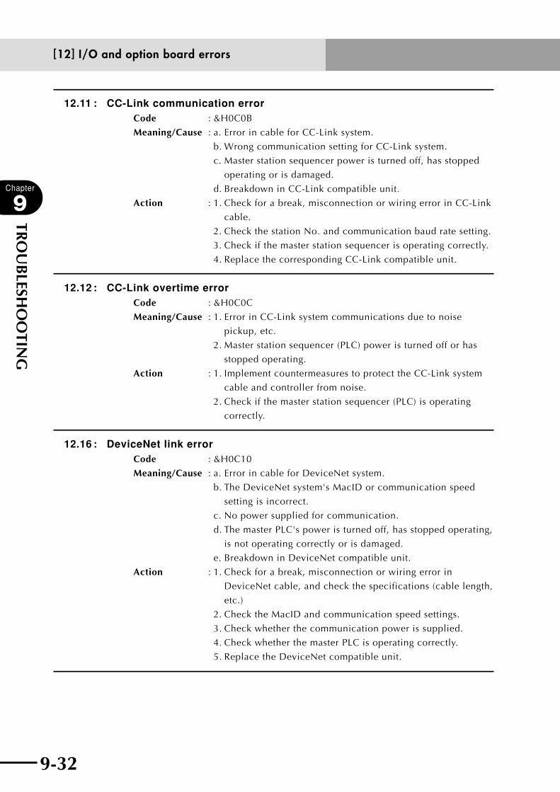
9-32
Chapter
9
TRO
UB
LESHO
OTIN
G
9-33
12.11 : CC-Link communication error Code : &H0C0B
Meaning/Cause : a. Error in cable for CC-Link system.
b. Wrong communication setting for CC-Link system.
c. Master station sequencer power is turned off, has stopped
operating or is damaged.
d. Breakdown in CC-Link compatible unit.
Action : 1. Check for a break, misconnection or wiring error in CC-Link
cable.
2. Check the station No. and communication baud rate setting.
3. Check if the master station sequencer is operating correctly.
4. Replace the corresponding CC-Link compatible unit.
12.12 : CC-Link overtime errorCode : &H0C0C
Meaning/Cause : 1. Error in CC-Link system communications due to noise
pickup, etc.
2. Master station sequencer (PLC) power is turned off or has
stopped operating.
Action : 1. Implement countermeasures to protect the CC-Link system
cable and controller from noise.
2. Check if the master station sequencer (PLC) is operating
correctly.
12.16 : DeviceNet link errorCode : &H0C10
Meaning/Cause : a. Error in cable for DeviceNet system.
b. The DeviceNet system's MacID or communication speed
setting is incorrect.
c. No power supplied for communication.
d. The master PLC's power is turned off, has stopped operating,
is not operating correctly or is damaged.
e. Breakdown in DeviceNet compatible unit.
Action : 1. Check for a break, misconnection or wiring error in
DeviceNet cable, and check the specifications (cable length,
etc.)
2. Check the MacID and communication speed settings.
3. Check whether the communication power is supplied.
4. Check whether the master PLC is operating correctly.
5. Replace the DeviceNet compatible unit.
[12] I/O and option board errors
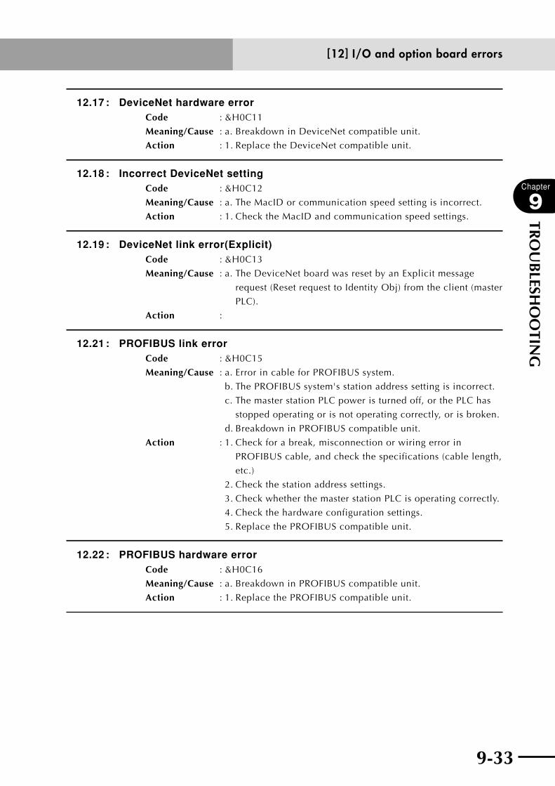
9-32 9-33
Chapter
9
TRO
UB
LESHO
OTIN
G
12.17 : DeviceNet hardware errorCode : &H0C11
Meaning/Cause : a. Breakdown in DeviceNet compatible unit.
Action : 1. Replace the DeviceNet compatible unit.
12.18 : Incorrect DeviceNet settingCode : &H0C12
Meaning/Cause : a. The MacID or communication speed setting is incorrect.
Action : 1. Check the MacID and communication speed settings.
12.19 : DeviceNet link error(Explicit)Code : &H0C13
Meaning/Cause : a. The DeviceNet board was reset by an Explicit message
request (Reset request to Identity Obj) from the client (master
PLC).
Action :
12.21 : PROFIBUS link errorCode : &H0C15
Meaning/Cause : a. Error in cable for PROFIBUS system.
b. The PROFIBUS system's station address setting is incorrect.
c. The master station PLC power is turned off, or the PLC has
stopped operating or is not operating correctly, or is broken.
d. Breakdown in PROFIBUS compatible unit.
Action : 1. Check for a break, misconnection or wiring error in
PROFIBUS cable, and check the specifications (cable length,
etc.)
2. Check the station address settings.
3. Check whether the master station PLC is operating correctly.
4. Check the hardware configuration settings.
5. Replace the PROFIBUS compatible unit.
12.22 : PROFIBUS hardware errorCode : &H0C16
Meaning/Cause : a. Breakdown in PROFIBUS compatible unit.
Action : 1. Replace the PROFIBUS compatible unit.
[12] I/O and option board errors
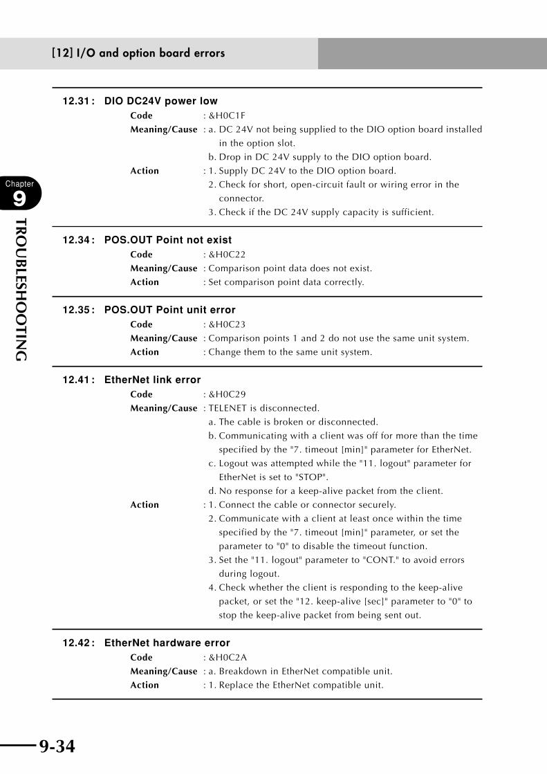
9-34
Chapter
9
TRO
UB
LESHO
OTIN
G
9-35
12.31 : DIO DC24V power lowCode : &H0C1F
Meaning/Cause : a. DC 24V not being supplied to the DIO option board installed
in the option slot.
b. Drop in DC 24V supply to the DIO option board.
Action : 1. Supply DC 24V to the DIO option board.
2. Check for short, open-circuit fault or wiring error in the
connector.
3. Check if the DC 24V supply capacity is sufficient.
12.34 : POS.OUT Point not exist Code : &H0C22
Meaning/Cause : Comparison point data does not exist.
Action : Set comparison point data correctly.
12.35 : POS.OUT Point unit error Code : &H0C23
Meaning/Cause : Comparison points 1 and 2 do not use the same unit system.
Action : Change them to the same unit system.
12.41 : EtherNet link errorCode : &H0C29
Meaning/Cause : TELENET is disconnected.
a. The cable is broken or disconnected.
b. Communicating with a client was off for more than the time
specified by the "7. timeout [min]" parameter for EtherNet.
c. Logout was attempted while the "11. logout" parameter for
EtherNet is set to "STOP".
d. No response for a keep-alive packet from the client.
Action : 1. Connect the cable or connector securely.
2. Communicate with a client at least once within the time
specified by the "7. timeout [min]" parameter, or set the
parameter to "0" to disable the timeout function.
3. Set the "11. logout" parameter to "CONT." to avoid errors
during logout.
4. Check whether the client is responding to the keep-alive
packet, or set the "12. keep-alive [sec]" parameter to "0" to
stop the keep-alive packet from being sent out.
12.42 : EtherNet hardware errorCode : &H0C2A
Meaning/Cause : a. Breakdown in EtherNet compatible unit.
Action : 1. Replace the EtherNet compatible unit.
[12] I/O and option board errors
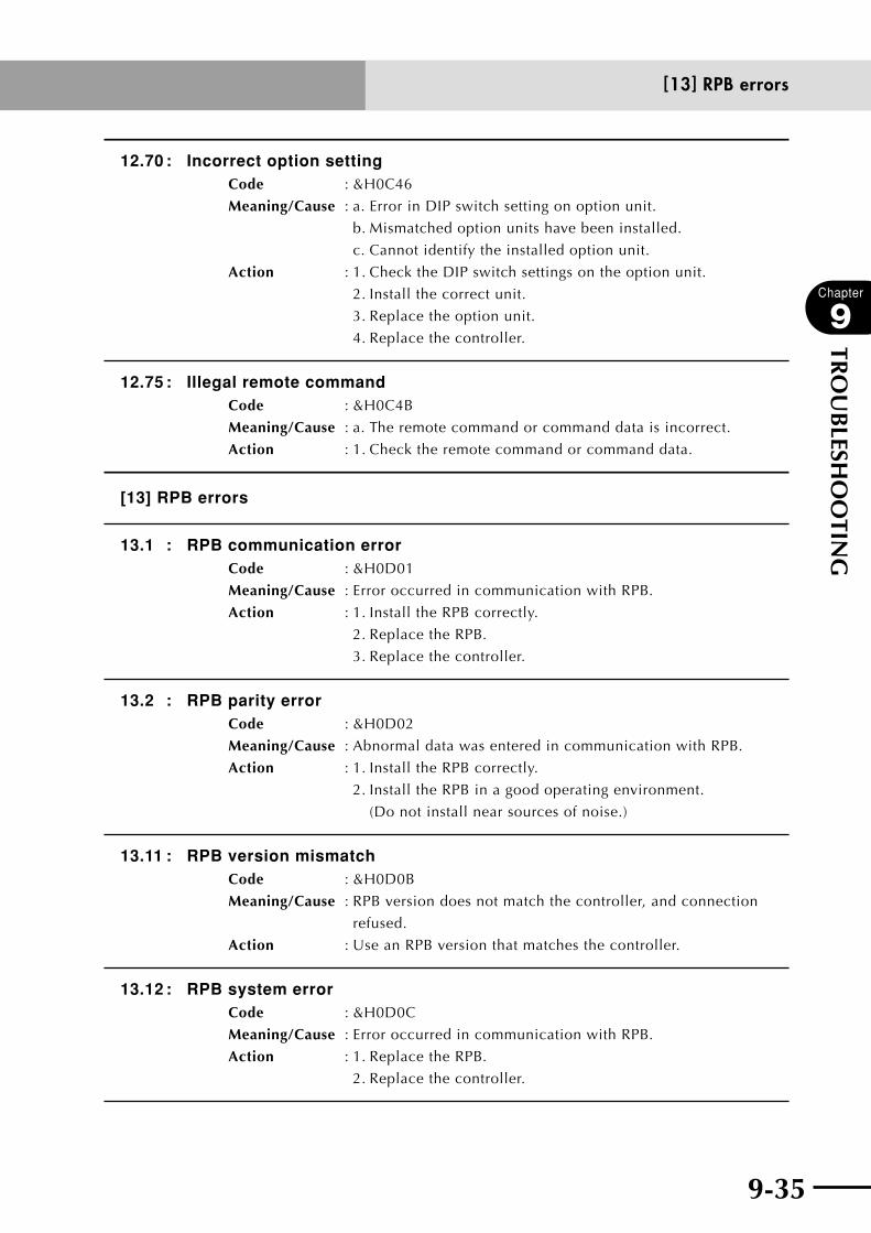
9-34 9-35
Chapter
9
TRO
UB
LESHO
OTIN
G
12.70 : Incorrect option settingCode : &H0C46
Meaning/Cause : a. Error in DIP switch setting on option unit.
b. Mismatched option units have been installed.
c. Cannot identify the installed option unit.
Action : 1. Check the DIP switch settings on the option unit.
2. Install the correct unit.
3. Replace the option unit.
4. Replace the controller.
12.75 : Illegal remote commandCode : &H0C4B
Meaning/Cause : a. The remote command or command data is incorrect.
Action : 1. Check the remote command or command data.
[13] RPB errors
13.1 : RPB communication errorCode : &H0D01
Meaning/Cause : Error occurred in communication with RPB.
Action : 1. Install the RPB correctly.
2. Replace the RPB.
3. Replace the controller.
13.2 : RPB parity errorCode : &H0D02
Meaning/Cause : Abnormal data was entered in communication with RPB.
Action : 1. Install the RPB correctly.
2. Install the RPB in a good operating environment.
(Do not install near sources of noise.)
13.11 : RPB version mismatchCode : &H0D0B
Meaning/Cause : RPB version does not match the controller, and connection
refused.
Action : Use an RPB version that matches the controller.
13.12 : RPB system errorCode : &H0D0C
Meaning/Cause : Error occurred in communication with RPB.
Action : 1. Replace the RPB.
2. Replace the controller.
[13] RPB errors

9-36
Chapter
9
TRO
UB
LESHO
OTIN
G
9-37
[14] RS-232C communication errors
14.1 : Communication errorCode : &H0E01
Meaning/Cause : a. During external communication via the RS-232C, an error
occurred.
b. An overrun error or framing error occurred via the RS-232C.
c. Power supply for external device turned on or off after
connecting communication cable with the external device.
Action : 1. Change to a correct system environment for RS-232C. (Do
not install near sources of noise.)
2. Replace the communications cable.
3. Check the communication parameter settings.
14.2 : Parity errorCode : &H0E02
Meaning/Cause : During external communication via the RS-232C, an error
occurred.
Action : Check the communication parameter settings.
14.11 : Receive buffer overflowCode : &H0E0B
Meaning/Cause : Communication receive buffer exceeded permissible capacity.
Action : 1. Delay the communication parameter speed (baud rate).
2. Change communication parameter so that flow control is
enabled.
14.12 : CMU is not readyCode : &H0E0C
Meaning/Cause : Could not sent data from controller because receive prohibit
status of other party continued for more than 10 seconds.
Action : 1. Replace the communications cable.
2. Check that flow control is normal in software processing for
other party.
14.20 : Too many Command charactersCode : &H0E14
Meaning/Cause : 1. Off-line command character string in 1 line exceeded 80
letters.
2. Command statement created with a remote command
exceeded 80 letters.
Action : 1. Limit number of characters in 1 line for an off-line command
to 80 letters or less.
2. Check the command data of the remote command.
[14] RS-232C communication errors

9-36 9-37
Chapter
9
TRO
UB
LESHO
OTIN
G
14.21 : No return code (C/R)Code : &H0E15
Meaning/Cause : 1. Character string in 1 line exceeded 75 letters.
2. CR code (0Dh) was not added at end of line.
Action : 1. Limit number of characters in 1 line to 75 letters.
2. Add a CR code at the end of a single line.
14.22 : No start code (@)Code : &H0E16
Meaning/Cause : Starting code "@" was not added at beginning of single line in
an on-line command.
Action : Add starting code "@" at the beginning of on-line command.
14.23 : Illegal command,OperatingCode : &H0E17
Meaning/Cause : During data editing, an on-line command was executed.
Action : After completing data edit, execute an on-line command.
14.24 : Illegal command,RunningCode : &H0E18
Meaning/Cause : During program run, a non-executable on-line command was
attempted.
Action : After stopping the program, execute the on-line system
command which could not previously be executed.
14.25 : Illegal command in this modeCode : &H0E19
Meaning/Cause : Cannot execute the specified online command in the current
mode.
Action : 1. Stop the online command.
2. Change the mode.
14.26 : Illegal command,SERVICE modeCode : &H0E1A
Meaning/Cause : Unable to execute since operation is in "SERVICE" mode.
Action : 1. Cancel "SERVICE" mode.
2. Change the exclusive control setting so it can be used in
"SERVICE" mode.
14.31 : Illegal port typeCode : &H0E1F
Meaning/Cause : Communication port not specified.
Action : Contact our company with details on this problem.
[14] RS-232C communication errors
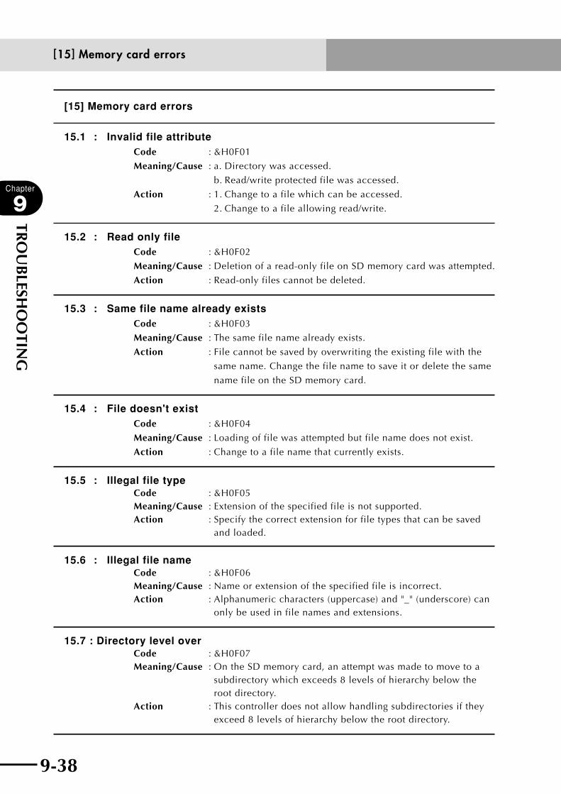
9-38
Chapter
9
TRO
UB
LESHO
OTIN
G
9-39
[15] Memory card errors
15.1 : Invalid file attributeCode : &H0F01
Meaning/Cause : a. Directory was accessed.
b. Read/write protected file was accessed.
Action : 1. Change to a file which can be accessed.
2. Change to a file allowing read/write.
15.2 : Read only file Code : &H0F02
Meaning/Cause : Deletion of a read-only file on SD memory card was attempted.
Action : Read-only files cannot be deleted.
15.3 : Same file name already exists Code : &H0F03
Meaning/Cause : The same file name already exists.
Action : File cannot be saved by overwriting the existing file with the
same name. Change the file name to save it or delete the same
name file on the SD memory card.
15.4 : File doesn't exist Code : &H0F04
Meaning/Cause : Loading of file was attempted but file name does not exist.
Action : Change to a file name that currently exists.
15.5 : Illegal file typeCode : &H0F05Meaning/Cause : Extension of the specified file is not supported.Action : Specify the correct extension for file types that can be saved
and loaded.
15.6 : Illegal file nameCode : &H0F06Meaning/Cause : Name or extension of the specified file is incorrect.Action : Alphanumeric characters (uppercase) and "_" (underscore) can
only be used in file names and extensions.
15.7 : Directory level overCode : &H0F07Meaning/Cause : On the SD memory card, an attempt was made to move to a
subdirectory which exceeds 8 levels of hierarchy below the root directory.
Action : This controller does not allow handling subdirectories if they exceed 8 levels of hierarchy below the root directory.
[15] Memory card errors

9-38 9-39
Chapter
9
TRO
UB
LESHO
OTIN
G
15.11 : Directory fullCode : &H0F0B
Meaning/Cause : The file storage capacity was exceeded.
Action : 1. Use a new memory card.
2. Change the directory to save.
3. Delete unnecessary files.
15.12 : Disk fullCode : &H0F0C
Meaning/Cause : Write failed. No space is available on memory card. (File
contents cannot be guaranteed.)
Action : 1. Use a new memory card.
2. Delete unnecessary files.
15.13 : Unformatted mediaCode : &H0F0D
Meaning/Cause : a. Memory card was not formatted.
b. Wrong memory card format.
Action : 1. Format correctly.
2. Replace memory card backup battery.
15.14 : Media protectedCode : &H0F0E
Meaning/Cause : Cannot write. Memory card has been set to write protect.
Action : 1. Change to allow writing.
2. Use another memory card.
15.15 : Media type mismatchCode : &H0F0F
Meaning/Cause : Memory card is unusable.
Action : Replace the memory card.
15.16 : Media data destroyedCode : &H0F10
Meaning/Cause : All or part of data stored on memory card is damaged.
Action : 1. Format the memory card.
2. Overwrite the damaged portion with new data.
3. Replace the memory card backup battery.
4. Replace the memory card.
15.21 : Cannot find mediaCode : &H0F15
Meaning/Cause : Memory card not inserted correctly in slot.
Action : Insert the memory card correctly.
[15] Memory card errors
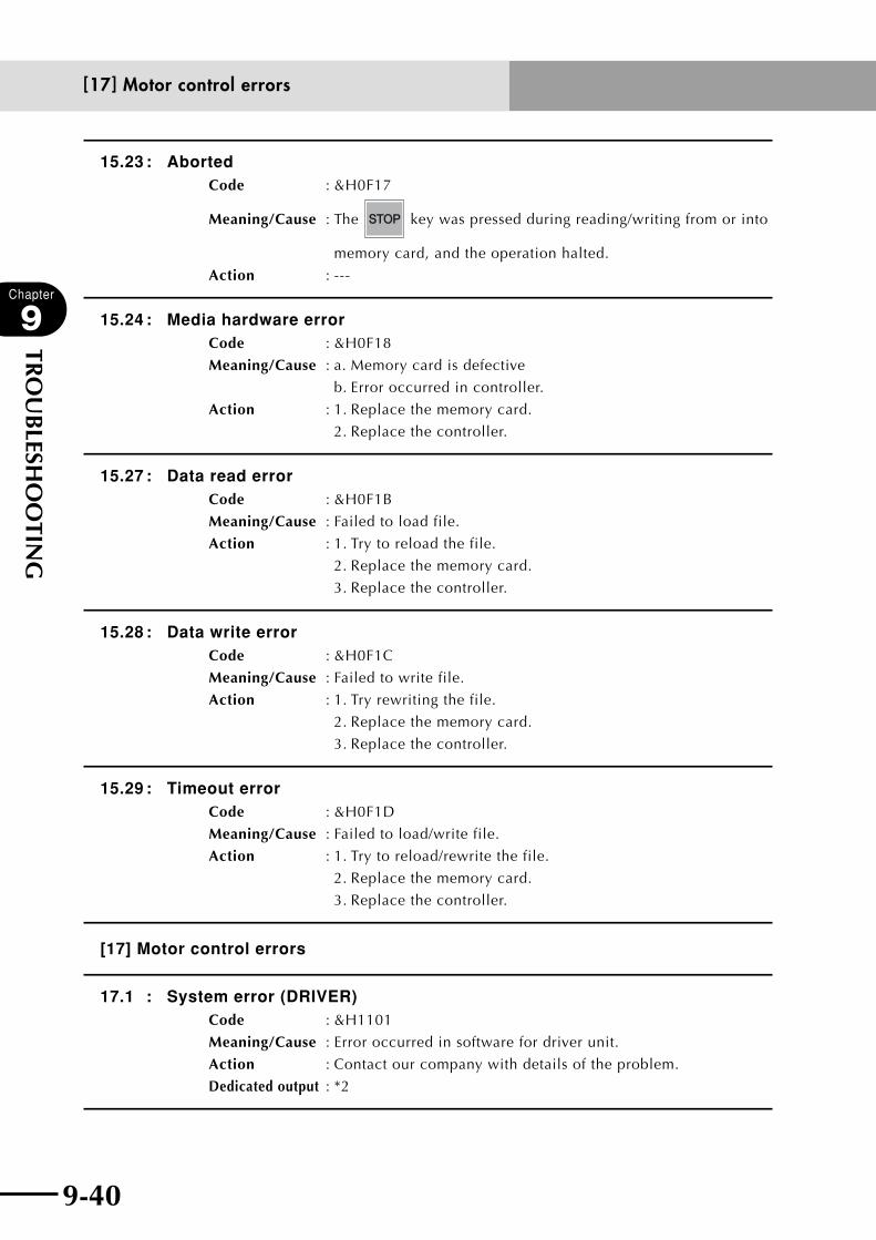
9-40
Chapter
9
TRO
UB
LESHO
OTIN
G
9-41
15.23 : AbortedCode : &H0F17
Meaning/Cause : The key was pressed during reading/writing from or into
memory card, and the operation halted.
Action : ---
15.24 : Media hardware errorCode : &H0F18
Meaning/Cause : a. Memory card is defective
b. Error occurred in controller.
Action : 1. Replace the memory card.
2. Replace the controller.
15.27 : Data read errorCode : &H0F1B
Meaning/Cause : Failed to load file.
Action : 1. Try to reload the file.
2. Replace the memory card.
3. Replace the controller.
15.28 : Data write errorCode : &H0F1C
Meaning/Cause : Failed to write file.
Action : 1. Try rewriting the file.
2. Replace the memory card.
3. Replace the controller.
15.29 : Timeout errorCode : &H0F1D
Meaning/Cause : Failed to load/write file.
Action : 1. Try to reload/rewrite the file.
2. Replace the memory card.
3. Replace the controller.
[17] Motor control errors
17.1 : System error (DRIVER)Code : &H1101
Meaning/Cause : Error occurred in software for driver unit.
Action : Contact our company with details of the problem.
Dedicated output : *2
[17] Motor control errors
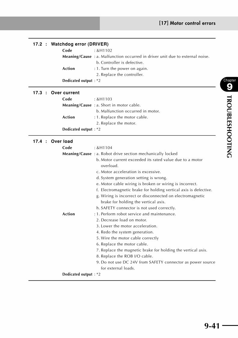
9-40 9-41
Chapter
9
TRO
UB
LESHO
OTIN
G
17.2 : Watchdog error (DRIVER)Code : &H1102
Meaning/Cause : a. Malfunction occurred in driver unit due to external noise.
b. Controller is defective.
Action : 1. Turn the power on again.
2. Replace the controller.
Dedicated output : *2
17.3 : Over currentCode : &H1103
Meaning/Cause : a. Short in motor cable.
b. Malfunction occurred in motor.
Action : 1. Replace the motor cable.
2. Replace the motor.
Dedicated output : *2
17.4 : Over loadCode : &H1104
Meaning/Cause : a. Robot drive section mechanically locked
b. Motor current exceeded its rated value due to a motor
overload.
c. Motor acceleration is excessive.
d. System generation setting is wrong.
e. Motor cable wiring is broken or wiring is incorrect.
f. Electromagnetic brake for holding vertical axis is defective.
g. Wiring is incorrect or disconnected on electromagnetic
brake for holding the vertical axis.
h. SAFETY connector is not used correctly.
Action : 1. Perform robot service and maintenance.
2. Decrease load on motor.
3. Lower the motor acceleration.
4. Redo the system generation.
5. Wire the motor cable correctly
6. Replace the motor cable.
7. Replace the magnetic brake for holding the vertical axis.
8. Replace the ROB I/O cable.
9. Do not use DC 24V from SAFETY connector as power source
for external loads.
Dedicated output : *2
[17] Motor control errors
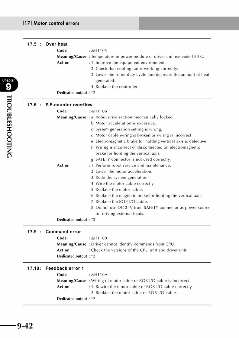
9-42
Chapter
9
TRO
UB
LESHO
OTIN
G
9-43
17.5 : Over heatCode : &H1105
Meaning/Cause : Temperature in power module of driver unit exceeded 80。C.
Action : 1. Improve the equipment environment.
2. Check that cooling fan is working correctly.
3. Lower the robot duty cycle and decrease the amount of heat
generated.
4. Replace the controller
Dedicated output : *2
17.6 : P.E.counter overflowCode : &H1106
Meaning/Cause : a. Robot drive section mechanically locked.
b. Motor acceleration is excessive.
c. System generation setting is wrong.
d. Motor cable wiring is broken or wiring is incorrect.
e. Electromagnetic brake for holding vertical axis is defective.
f. Wiring is incorrect or disconnected on electromagnetic
brake for holding the vertical axis.
g. SAFETY connector is not used correctly.
Action : 1. Perform robot service and maintenance.
2. Lower the motor acceleration.
3. Redo the system generation.
4. Wire the motor cable correctly
5. Replace the motor cable.
6. Replace the magnetic brake for holding the vertical axis.
7. Replace the ROB I/O cable.
8. Do not use DC 24V from SAFETY connector as power source
for driving external loads.
Dedicated output : *2
17.9 : Command errorCode : &H1109
Meaning/Cause : Driver cannot identify commands from CPU.
Action : Check the versions of the CPU unit and driver unit.
Dedicated output : *2
17.10 : Feedback error 1Code : &H110A
Meaning/Cause : Wiring of motor cable or ROB I/O cable is incorrect.
Action : 1. Rewire the motor cable or ROB I/O cable correctly.
2. Replace the motor cable or ROB I/O cable.
Dedicated output : *2
[17] Motor control errors

9-42 9-43
Chapter
9
TRO
UB
LESHO
OTIN
G
17.11 : Feedback error 2Code : &H110B
Meaning/Cause : Motor cable is broken.
Action : Replace the motor cable or encoder cable.
Dedicated output : *2
17.16 : Over velocity 1Code : &H1110
Meaning/Cause : Axis movement speed exceeded the limit during linear
interpolation, circular interpolation or manual orthogonal
movement.
Action : 1. Reduce the acceleration.
2. Reduce the speed.
Dedicated output : *2
17.17 : Mode errorCode : &H1111
Meaning/Cause : Driver unit is in abnormal control mode status.
Action : Contact our company with details on the problem.
Dedicated output : *2
17.18 : DPRAM data errorCode : &H1112
Meaning/Cause : Two tries at loading the dual port RAM failed.
Action : Contact our company with details on the problem.
Dedicated output : *2
17.19 : Coord. value errorCode : &H1113
Meaning/Cause : Error occurred during linear interpolation, circular interpolation
or manual orthogonal movement.
Action : Contact our company with details on the problem.
Dedicated output : *2
17.20 : Motor type errorCode : &H1114
Meaning/Cause : A motor type unidentifiable by drive unit was selected.
Action : 1. Redo the system generation.
2. Replace the controller.
[17] Motor control errors
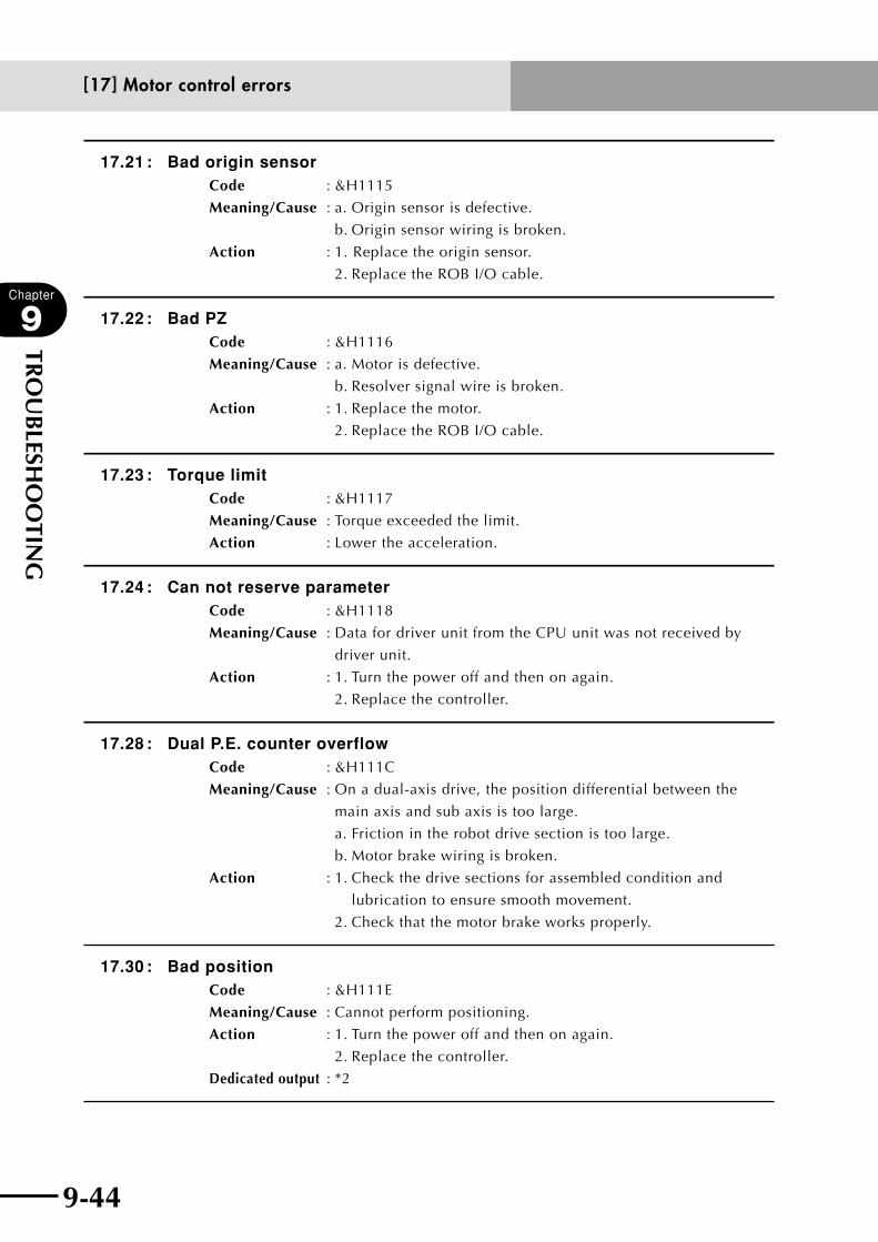
9-44
Chapter
9
TRO
UB
LESHO
OTIN
G
9-45
17.21 : Bad origin sensorCode : &H1115
Meaning/Cause : a. Origin sensor is defective.
b. Origin sensor wiring is broken.
Action : 1. Replace the origin sensor.
2. Replace the ROB I/O cable.
17.22 : Bad PZCode : &H1116
Meaning/Cause : a. Motor is defective.
b. Resolver signal wire is broken.
Action : 1. Replace the motor.
2. Replace the ROB I/O cable.
17.23 : Torque limitCode : &H1117
Meaning/Cause : Torque exceeded the limit.
Action : Lower the acceleration.
17.24 : Can not reserve parameterCode : &H1118
Meaning/Cause : Data for driver unit from the CPU unit was not received by
driver unit.
Action : 1. Turn the power off and then on again.
2. Replace the controller.
17.28 : Dual P.E. counter overflowCode : &H111C
Meaning/Cause : On a dual-axis drive, the position differential between the
main axis and sub axis is too large.
a. Friction in the robot drive section is too large.
b. Motor brake wiring is broken.
Action : 1. Check the drive sections for assembled condition and
lubrication to ensure smooth movement.
2. Check that the motor brake works properly.
17.30 : Bad positionCode : &H111E
Meaning/Cause : Cannot perform positioning.
Action : 1. Turn the power off and then on again.
2. Replace the controller.
Dedicated output : *2
[17] Motor control errors

9-44 9-45
Chapter
9
TRO
UB
LESHO
OTIN
G
17.31 : Servo offCode : &H111F
Meaning/Cause : Movement command was attempted in servo OFF state.
Action : Change status to servo ON.
17.33 : Busy nowCode : &H1121
Meaning/Cause : a. Servo-Off command was attempted while the driver was
stopped.
b. Return-to-origin command was attempted before manual
movement was complete.
Action : 1. Turn off the power to the controller and then turn it back on.
2. Wait until the command has finished.
Dedicated output : *2
17.34 : Servo on failedCode : &H1122
Meaning/Cause : a. Servo-ON was attempted for each axis while motor power
was off.
b. Servo-ON processing failed because the drive unit had been
stopped.
Action : 1. First turn on the motor power if servo-ON for each axis was
attempted.
2. Turn the power off and then on again.
17.35 : Axis weight overCode : &H1123
Meaning/Cause : The weight (sum of work weight + axis weight) on a particular
robot axis exceeded the maximum payload of that axis.
Action : 1. Redo the system generation.
2. Select the axis weight parameter to a correct value.
17.39 : Servo off failedCode : &H1127
Meaning/Cause : Servo-OFF processing failed because the drive unit had been
stopped.
Action : Turn the power off and then on again.
Dedicated output : *2
17.40 : Torque mode nowCode : &H1128
Meaning/Cause : Manual movement attempted while in torque mode.
Action : Cancel the torque mode.
[17] Motor control errors

9-46
Chapter
9
TRO
UB
LESHO
OTIN
G
9-47
17.73 : Resolver wire breakageCode : &H1149
Meaning/Cause : a. Resolver signal wire is broken.
b. Motor malfunction occurred.
c. Controller malfunction occurred.
Action : 1. Replace the ROB I/O cable.
2. Replace the motor.
3. Replace the controller.
17.78 : Power module errorCode : &H114E
Meaning/Cause : a. Power module overheated.
b. Power module/motor drew excessive current.
Action : Lighten the load on the robot.
17.82 : CS read errorCode : &H1152
Meaning/Cause : Readout check of resolver electrical angle information failed
twice
Action : 1. Perform return-to-origin.
2. Replace the motor.
3. Replace the controller.
17.90 : DRIVE2 module type errorCode : &H115A
Meaning/Cause : Motor specifications do not match current sensor specifications.
Action : 1. Replace the controller.
2. Redo the system generation.
17.99 : Pole Search ErrorCode : &H1163
Meaning/Cause : Failed to detect the motor magnetic pole when the servo was
turned on.
a. Servo wire is broken or misconnected.
b. Position sensor cable is miswired.
c. Axis parameter setting related to motor control is wrong.
Action : 1. Correct the motor wiring.
2. Check the position sensor cable wiring.
3. Correct the parameter setting.
[17] Motor control errors
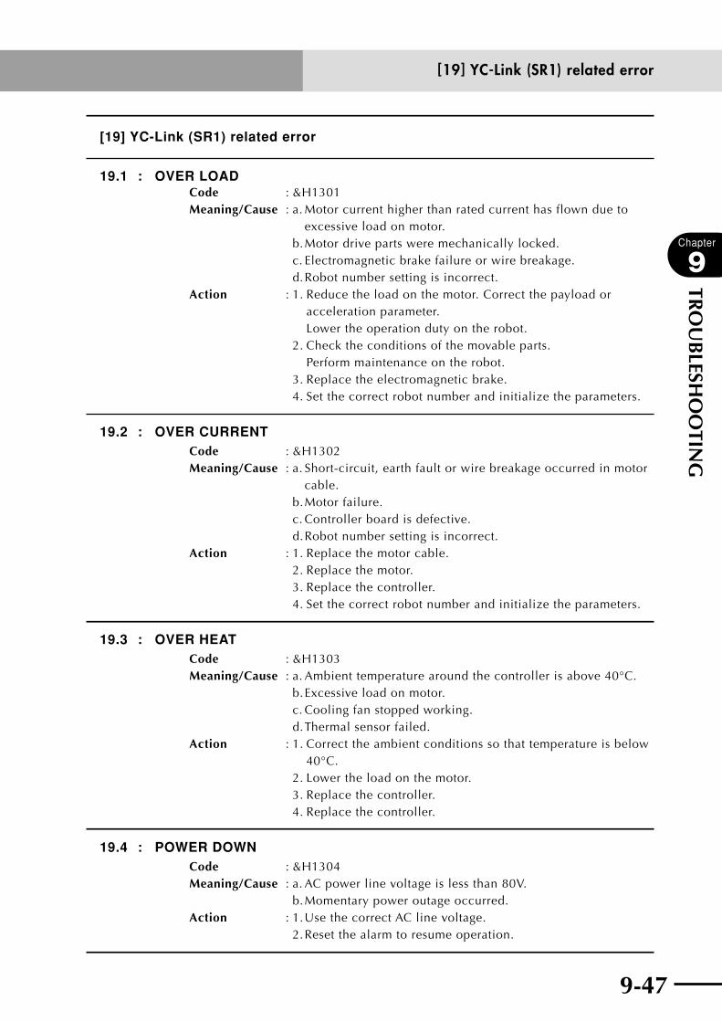
9-46 9-47
Chapter
9
TRO
UB
LESHO
OTIN
G
[19] YC-Link (SR1) related error
19.1 : OVER LOADCode : &H1301Meaning/Cause : a. Motor current higher than rated current has flown due to
excessive load on motor. b. Motor drive parts were mechanically locked. c. Electromagnetic brake failure or wire breakage. d. Robot number setting is incorrect.Action : 1. Reduce the load on the motor. Correct the payload or
acceleration parameter. Lower the operation duty on the robot.
2. Check the conditions of the movable parts. Perform maintenance on the robot.
3. Replace the electromagnetic brake. 4. Set the correct robot number and initialize the parameters.
19.2 : OVER CURRENTCode : &H1302Meaning/Cause : a. Short-circuit, earth fault or wire breakage occurred in motor
cable. b. Motor failure. c. Controller board is defective. d. Robot number setting is incorrect.Action : 1. Replace the motor cable. 2. Replace the motor. 3. Replace the controller. 4. Set the correct robot number and initialize the parameters.
19.3 : OVER HEATCode : &H1303Meaning/Cause : a. Ambient temperature around the controller is above 40°C.
b. Excessive load on motor. c. Cooling fan stopped working. d. Thermal sensor failed.
Action : 1. Correct the ambient conditions so that temperature is below 40°C.
2. Lower the load on the motor. 3. Replace the controller. 4. Replace the controller.
19.4 : POWER DOWNCode : &H1304Meaning/Cause : a. AC power line voltage is less than 80V.
b. Momentary power outage occurred.Action : 1. Use the correct AC line voltage.
2. Reset the alarm to resume operation.
[19] YC-Link (SR1) related error

9-48
Chapter
9
TRO
UB
LESHO
OTIN
G
9-49
19.5 : BATT.LOW-VOLTAGECode : &H1305Meaning/Cause : a. Battery connection is incorrect.
b. Battery voltage is lower than specified.
Action : 1. Connect the battery correctly.
2. Replace the battery.
19.6 : 24V POWER OFFCode : &H1306Meaning/Cause : Internal 24V circuit failure.
Controller board failed.
Action : Replace the controller.
19.7 : P.E. COUNTER OVERCode : &H1307Meaning/Cause : Deviation counter error.
Action : −−−
19.11 : SYSTEM FAULTCode : &H130B
Meaning/Cause : a. Driver was not recognized correctly at power-on.
b. External noise has disrupted software program.
c. RS-232C receiving buffer has overflown.
Action : 1. Replace the controller.
2. Check the environment for noise.
3. Select the XON/XOFF control with the host device.
19.12 : BAD ORG-SENSORCode : &H130C
Meaning/Cause : a. Origin sensor connection is incorrect.
b. Origin sensor wire broke or sensor became defective.
c. Origin sensor dog (target) is not properly adjusted.
Action : 1. Connect the origin sensor correctly.
2. Replace the origin sensor.
3. Adjust the origin sensor dog correctly.
19.13 : BAD PZCode : &H130D
Meaning/Cause : a. Position detector failure.
b. Phase Z detection error.
Action : 1. Replace the motor or robot.
2. Connect the ROB I/O cable correctly.
Replace the ROB I/O cable.
[19] YC-Link (SR1) related error
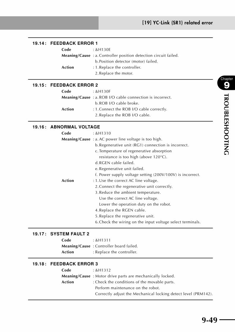
9-48 9-49
Chapter
9
TRO
UB
LESHO
OTIN
G
19.14 : FEEDBACK ERROR 1Code : &H130E
Meaning/Cause : a. Controller position detection circuit failed.
b. Position detector (motor) failed.
Action : 1. Replace the controller.
2. Replace the motor.
19.15 : FEEDBACK ERROR 2Code : &H130F
Meaning/Cause : a. ROB I/O cable connection is incorrect.
b. ROB I/O cable broke.
Action : 1. Connect the ROB I/O cable correctly.
2. Replace the ROB I/O cable.
19.16 : ABNORMAL VOLTAGECode : &H1310
Meaning/Cause : a. AC power line voltage is too high.
b. Regenerative unit (RG1) connection is incorrect.
c. Temperature of regenerative absorption
resistance is too high (above 120°C).
d. RGEN cable failed.
e. Regenerative unit failed.
f. Power supply voltage setting (200V/100V) is incorrect.
Action : 1. Use the correct AC line voltage.
2. Connect the regenerative unit correctly.
3. Reduce the ambient temperature.
Use the correct AC line voltage.
Lower the operation duty on the robot.
4. Replace the RGEN cable.
5. Replace the regenerative unit.
6. Check the wiring on the input voltage select terminals.
19.17 : SYSTEM FAULT 2Code : &H1311
Meaning/Cause : Controller board failed.
Action : Replace the controller.
19.18 : FEEDBACK ERROR 3Code : &H1312
Meaning/Cause : Motor drive parts are mechanically locked.
Action : Check the conditions of the movable parts.
Perform maintenance on the robot.
Correctly adjust the Mechanical locking detect level (PRM142).
[19] YC-Link (SR1) related error
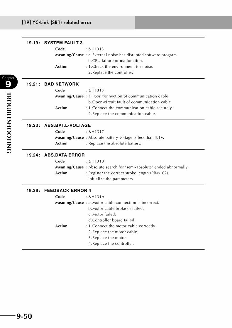
9-50
Chapter
9
TRO
UB
LESHO
OTIN
G
9-51
19.19 : SYSTEM FAULT 3Code : &H1313
Meaning/Cause : a. External noise has disrupted software program.
b. CPU failure or malfunction.
Action : 1. Check the environment for noise.
2. Replace the controller.
19.21 : BAD NETWORKCode : &H1315
Meaning/Cause : a. Poor connection of communication cable
b. Open-circuit fault of communication cable
Action : 1. Connect the communication cable securely.
2. Replace the communication cable.
19.23 : ABS.BAT.L-VOLTAGECode : &H1317
Meaning/Cause : Absolute battery voltage is less than 3.1V.
Action : Replace the absolute battery.
19.24 : ABS.DATA ERRORCode : &H1318
Meaning/Cause : Absolute search for "semi-absolute" ended abnormally.
Action : Register the correct stroke length (PRM102).
Initialize the parameters.
19.26 : FEEDBACK ERROR 4Code : &H131A
Meaning/Cause : a. Motor cable connection is incorrect.
b. Motor cable broke or failed.
c. Motor failed.
d. Controller board failed.
Action : 1. Connect the motor cable correctly.
2. Replace the motor cable.
3. Replace the motor.
4. Replace the controller.
[19] YC-Link (SR1) related error
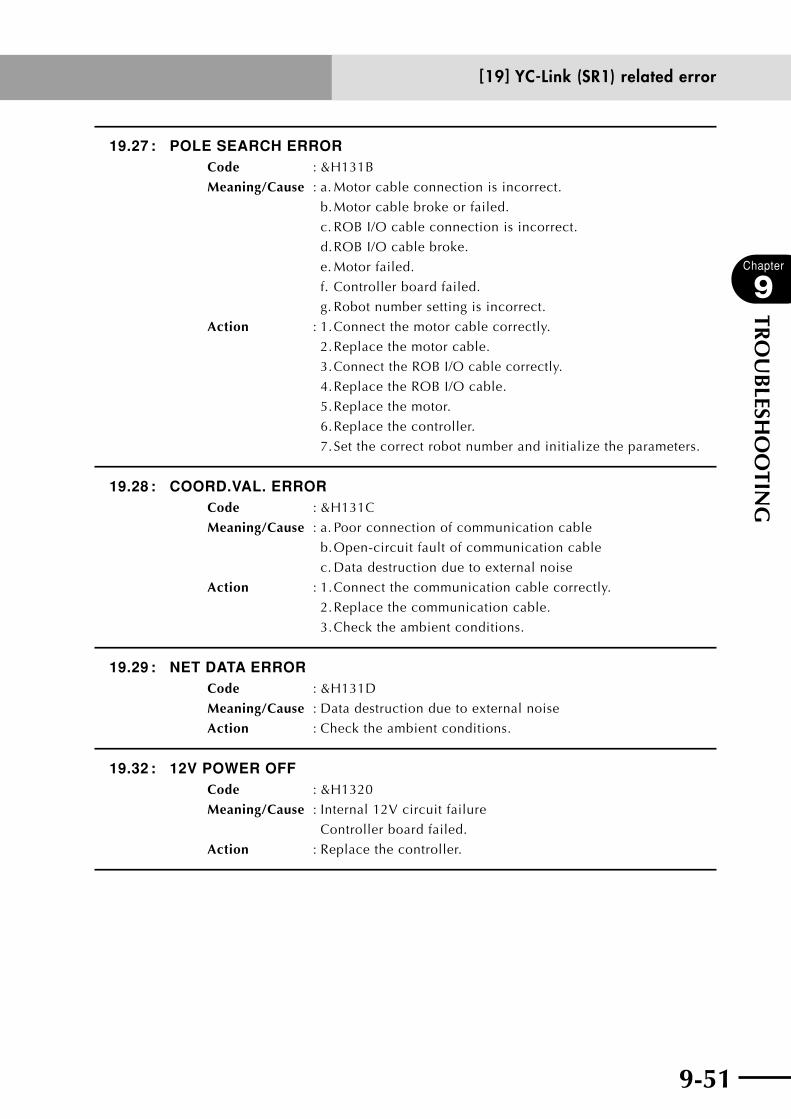
9-50 9-51
Chapter
9
TRO
UB
LESHO
OTIN
G
19.27 : POLE SEARCH ERRORCode : &H131B
Meaning/Cause : a. Motor cable connection is incorrect.
b. Motor cable broke or failed.
c. ROB I/O cable connection is incorrect.
d. ROB I/O cable broke.
e. Motor failed.
f. Controller board failed.
g. Robot number setting is incorrect.
Action : 1. Connect the motor cable correctly.
2. Replace the motor cable.
3. Connect the ROB I/O cable correctly.
4. Replace the ROB I/O cable.
5. Replace the motor.
6. Replace the controller.
7. Set the correct robot number and initialize the parameters.
19.28 : COORD.VAL. ERRORCode : &H131C
Meaning/Cause : a. Poor connection of communication cable
b. Open-circuit fault of communication cable
c. Data destruction due to external noise
Action : 1. Connect the communication cable correctly.
2. Replace the communication cable.
3. Check the ambient conditions.
19.29 : NET DATA ERRORCode : &H131D
Meaning/Cause : Data destruction due to external noise
Action : Check the ambient conditions.
19.32 : 12V POWER OFFCode : &H1320
Meaning/Cause : Internal 12V circuit failure
Controller board failed.
Action : Replace the controller.
[19] YC-Link (SR1) related error
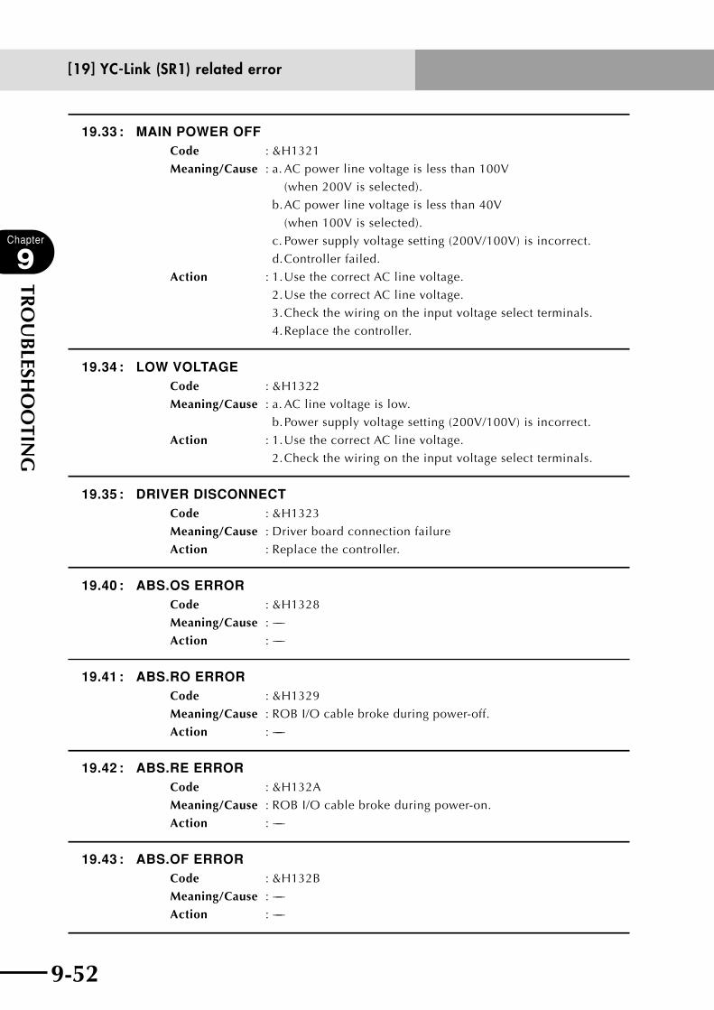
9-52
Chapter
9
TRO
UB
LESHO
OTIN
G
9-53
19.33 : MAIN POWER OFFCode : &H1321
Meaning/Cause : a. AC power line voltage is less than 100V
(when 200V is selected).
b. AC power line voltage is less than 40V
(when 100V is selected).
c. Power supply voltage setting (200V/100V) is incorrect. d. Controller failed.
Action : 1. Use the correct AC line voltage.
2. Use the correct AC line voltage.
3. Check the wiring on the input voltage select terminals.
4. Replace the controller.
19.34 : LOW VOLTAGECode : &H1322
Meaning/Cause : a. AC line voltage is low.
b. Power supply voltage setting (200V/100V) is incorrect.
Action : 1. Use the correct AC line voltage.
2. Check the wiring on the input voltage select terminals.
19.35 : DRIVER DISCONNECTCode : &H1323
Meaning/Cause : Driver board connection failure
Action : Replace the controller.
19.40 : ABS.OS ERRORCode : &H1328
Meaning/Cause : −−−
Action : −−−
19.41 : ABS.RO ERRORCode : &H1329
Meaning/Cause : ROB I/O cable broke during power-off.
Action : −−−
19.42 : ABS.RE ERRORCode : &H132A
Meaning/Cause : ROB I/O cable broke during power-on.
Action : −−−
19.43 : ABS.OF ERRORCode : &H132B
Meaning/Cause : −−−
Action : −−−
[19] YC-Link (SR1) related error
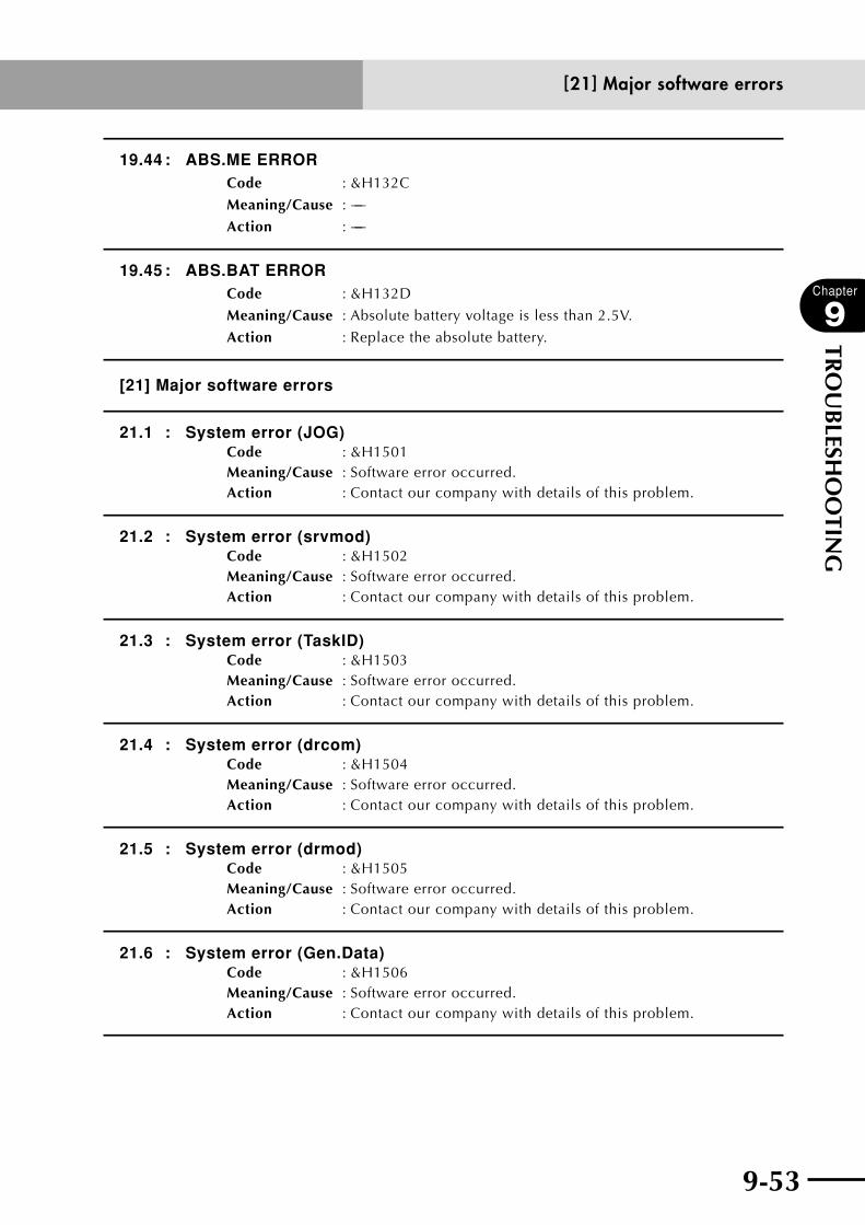
9-52 9-53
Chapter
9
TRO
UB
LESHO
OTIN
G
19.44 : ABS.ME ERRORCode : &H132C
Meaning/Cause : −−−
Action : −−−
19.45 : ABS.BAT ERRORCode : &H132D
Meaning/Cause : Absolute battery voltage is less than 2.5V.
Action : Replace the absolute battery.
[21] Major software errors
21.1 : System error (JOG)Code : &H1501Meaning/Cause : Software error occurred.Action : Contact our company with details of this problem.
21.2 : System error (srvmod)Code : &H1502Meaning/Cause : Software error occurred.Action : Contact our company with details of this problem.
21.3 : System error (TaskID)Code : &H1503Meaning/Cause : Software error occurred.Action : Contact our company with details of this problem.
21.4 : System error (drcom)Code : &H1504Meaning/Cause : Software error occurred.Action : Contact our company with details of this problem.
21.5 : System error (drmod)Code : &H1505Meaning/Cause : Software error occurred.Action : Contact our company with details of this problem.
21.6 : System error (Gen.Data)Code : &H1506Meaning/Cause : Software error occurred.Action : Contact our company with details of this problem.
[21] Major software errors
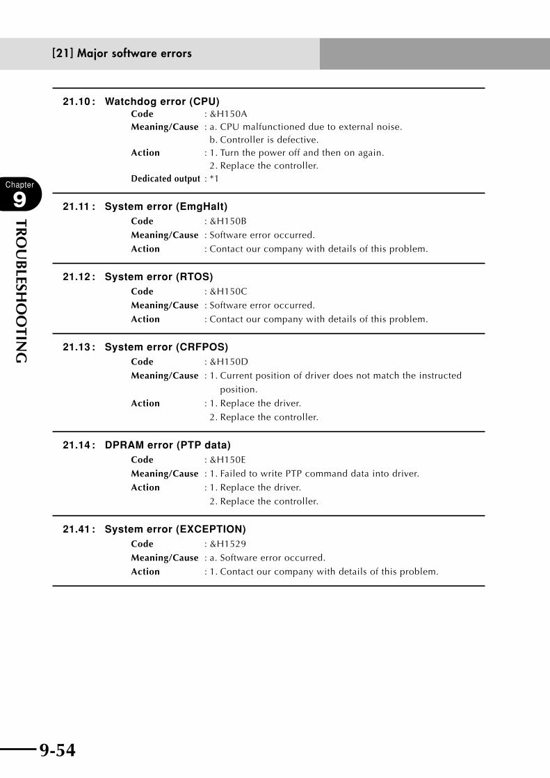
9-54
Chapter
9
TRO
UB
LESHO
OTIN
G
9-55
21.10 : Watchdog error (CPU)Code : &H150AMeaning/Cause : a. CPU malfunctioned due to external noise. b. Controller is defective.Action : 1. Turn the power off and then on again. 2. Replace the controller.Dedicated output : *1
21.11 : System error (EmgHalt)Code : &H150B
Meaning/Cause : Software error occurred.
Action : Contact our company with details of this problem.
21.12 : System error (RTOS)Code : &H150C
Meaning/Cause : Software error occurred.
Action : Contact our company with details of this problem.
21.13 : System error (CRFPOS)Code : &H150D
Meaning/Cause : 1. Current position of driver does not match the instructed
position.
Action : 1. Replace the driver.
2. Replace the controller.
21.14 : DPRAM error (PTP data)Code : &H150E
Meaning/Cause : 1. Failed to write PTP command data into driver.
Action : 1. Replace the driver.
2. Replace the controller.
21.41 : System error (EXCEPTION)Code : &H1529
Meaning/Cause : a. Software error occurred.
Action : 1. Contact our company with details of this problem.
[21] Major software errors

9-54 9-55
Chapter
9
TRO
UB
LESHO
OTIN
G
[22] Major hardware errors
22.1 : AC power lowCode : &H1601
Meaning/Cause : a. AC supply voltage dropped below 85% of rated voltage.
b. Power source has insufficient capacity.
Action : 1. Check the AC supply voltage
2. Check if supply voltage drops during robot operation.
3. Lower the robot duty cycle.
Dedicated output : *1
Caution : This error always occurs when the power is cut off.
22.3 : DC24V power lowCode : &H1603
Meaning/Cause : a. DC 24V power supply malfunctioned and the voltage
dropped.
b. Electromagnetic brake for vertical axis is defective.
c. Wiring for electromagnetic brake of vertical axis is wrong.
d. Short in DC 24V for safety connector.
Action : 1. Replace the controller.
2. Replace the vertical axis electromagnetic brake.
3. Replace the ROB I/O cable.
4. Check the SAFETY connector wiring.
Dedicated output : *1
22.7 : Main power lowCode : &H1607
Meaning/Cause : Main power voltage dropped when the servo was turned on or
during servo-on.
Action : Check whether main power is input.
[22] Major hardware errors
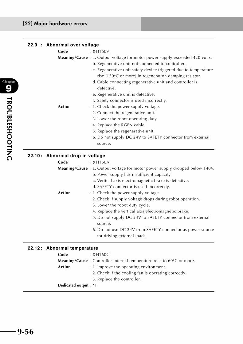
9-56
Chapter
9
TRO
UB
LESHO
OTIN
G
9-57
22.9 : Abnormal over voltageCode : &H1609
Meaning/Cause : a. Output voltage for motor power supply exceeded 420 volts.
b. Regenerative unit not connected to controller.
c. Regenerative unit safety device triggered due to temperature
rise (120°C or more) in regeneration damping resistor.
d. Cable connecting regenerative unit and controller is
defective.
e. Regenerative unit is defective.
f. Safety connector is used incorrectly.
Action : 1. Check the power supply voltage.
2. Connect the regenerative unit.
3. Lower the robot operating duty.
4. Replace the RGEN cable.
5. Replace the regenerative unit.
6. Do not supply DC 24V to SAFETY connector from external
source.
22.10 : Abnormal drop in voltageCode : &H160A
Meaning/Cause : a. Output voltage for motor power supply dropped below 140V.
b. Power supply has insufficient capacity.
c. Vertical axis electromagnetic brake is defective.
d. SAFETY connector is used incorrectly.
Action : 1. Check the power supply voltage.
2. Check if supply voltage drops during robot operation.
3. Lower the robot duty cycle.
4. Replace the vertical axis electromagnetic brake.
5. Do not supply DC 24V to SAFETY connector from external
source.
6. Do not use DC 24V from SAFETY connector as power source
for driving external loads.
22.12 : Abnormal temperatureCode : &H160C
Meaning/Cause : Controller internal temperature rose to 60°C or more.
Action : 1. Improve the operating environment.
2. Check if the cooling fan is operating correctly.
3. Replace the controller.
Dedicated output : *1
[22] Major hardware errors

9-56 9-57
Chapter
9
TRO
UB
LESHO
OTIN
G
22.13 : Bus interface overtimeCode : &H160D
Meaning/Cause : Could not acquire access rights to dual port RAM.
Action : Replace the controller.
Dedicated output : *1
22.14 : Abnormal DRIVER unit errorCode : &H160E
Meaning/Cause : Error occurred in hardware.
Action : Contact our company with details of the problem.
Dedicated output : *1
22.18 : RGEN overheatCode : &H1612
Meaning/Cause : Regenerative unit overheated.
Thermal sensor cable for regenerative unit is disconnected.
Action : 1. When a regenerative unit is used, check the thermal sensor
cable connection. If connection is correct, review the robot
operating conditions, etc.
2. When no regenerative unit is used, plug the shorting
connector into the connector for the thermal sensor cable.
22.20 : DRIVER unit disconnectedCode : &H1614
Meaning/Cause : 1. CPU unit could not recognize driver unit.
2. Dual port RAM is defective.
Action : Replace the controller.
Dedicated output : *1
22.30 : DRIVER unit abnormalityCode : &H161E
Meaning/Cause : 1. Wrong DIP switch setting on drive unit.
2. Drive unit not operating correctly.
3. Dual port RAM is defective.
Action : Replace the controller.
Dedicated output : *1 or *2
22.40 : PCMCIA interface overtimeCode : &H1628
Meaning/Cause : 1. Failed to acquire access privilege for PCMCIA interface.
Action : 1. Replace the PCMCIA interface driver.
: 2. Replace the controller.
Dedicated output : *1
[22] Major hardware errors
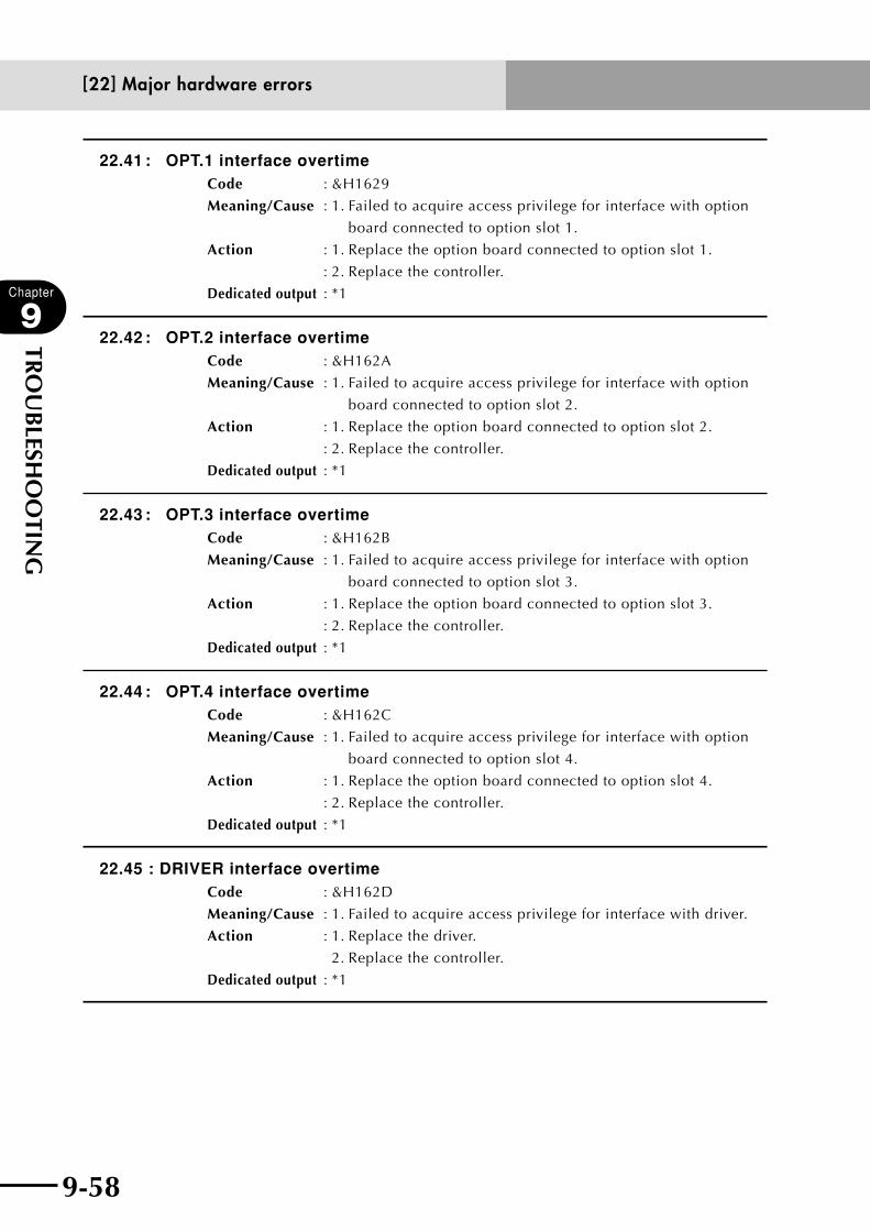
9-58
Chapter
9
TRO
UB
LESHO
OTIN
G
9-59
22.41 : OPT.1 interface overtimeCode : &H1629
Meaning/Cause : 1. Failed to acquire access privilege for interface with option
board connected to option slot 1.
Action : 1. Replace the option board connected to option slot 1.
: 2. Replace the controller.
Dedicated output : *1
22.42 : OPT.2 interface overtimeCode : &H162A
Meaning/Cause : 1. Failed to acquire access privilege for interface with option
board connected to option slot 2.
Action : 1. Replace the option board connected to option slot 2.
: 2. Replace the controller.
Dedicated output : *1
22.43 : OPT.3 interface overtimeCode : &H162B
Meaning/Cause : 1. Failed to acquire access privilege for interface with option
board connected to option slot 3.
Action : 1. Replace the option board connected to option slot 3.
: 2. Replace the controller.
Dedicated output : *1
22.44 : OPT.4 interface overtimeCode : &H162C
Meaning/Cause : 1. Failed to acquire access privilege for interface with option
board connected to option slot 4.
Action : 1. Replace the option board connected to option slot 4.
: 2. Replace the controller.
Dedicated output : *1
22.45 : DRIVER interface overtimeCode : &H162D
Meaning/Cause : 1. Failed to acquire access privilege for interface with driver.
Action : 1. Replace the driver.
2. Replace the controller.
Dedicated output : *1
[22] Major hardware errors
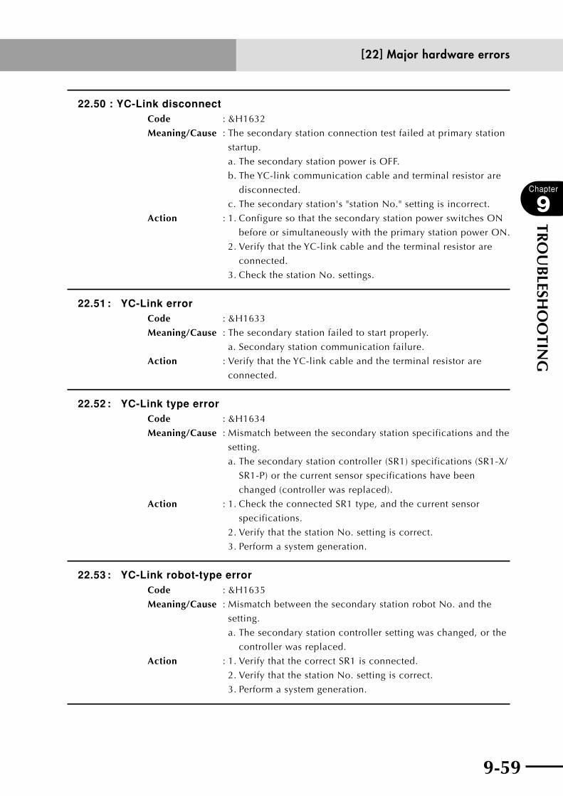
9-58 9-59
Chapter
9
TRO
UB
LESHO
OTIN
G
22.50 : YC-Link disconnectCode : &H1632
Meaning/Cause : The secondary station connection test failed at primary station
startup.
a. The secondary station power is OFF.
b. The YC-link communication cable and terminal resistor are
disconnected.
c. The secondary station's "station No." setting is incorrect.
Action : 1. Configure so that the secondary station power switches ON
before or simultaneously with the primary station power ON.
2. Verify that the YC-link cable and the terminal resistor are
connected.
3. Check the station No. settings.
22.51 : YC-Link errorCode : &H1633
Meaning/Cause : The secondary station failed to start properly.
a. Secondary station communication failure.
Action : Verify that the YC-link cable and the terminal resistor are
connected.
22.52 : YC-Link type errorCode : &H1634
Meaning/Cause : Mismatch between the secondary station specifications and the
setting.
a. The secondary station controller (SR1) specifications (SR1-X/
SR1-P) or the current sensor specifications have been
changed (controller was replaced).
Action : 1. Check the connected SR1 type, and the current sensor
specifications.
2. Verify that the station No. setting is correct.
3. Perform a system generation.
22.53 : YC-Link robot-type errorCode : &H1635
Meaning/Cause : Mismatch between the secondary station robot No. and the
setting.
a. The secondary station controller setting was changed, or the
controller was replaced.
Action : 1. Verify that the correct SR1 is connected.
2. Verify that the station No. setting is correct.
3. Perform a system generation.
[22] Major hardware errors
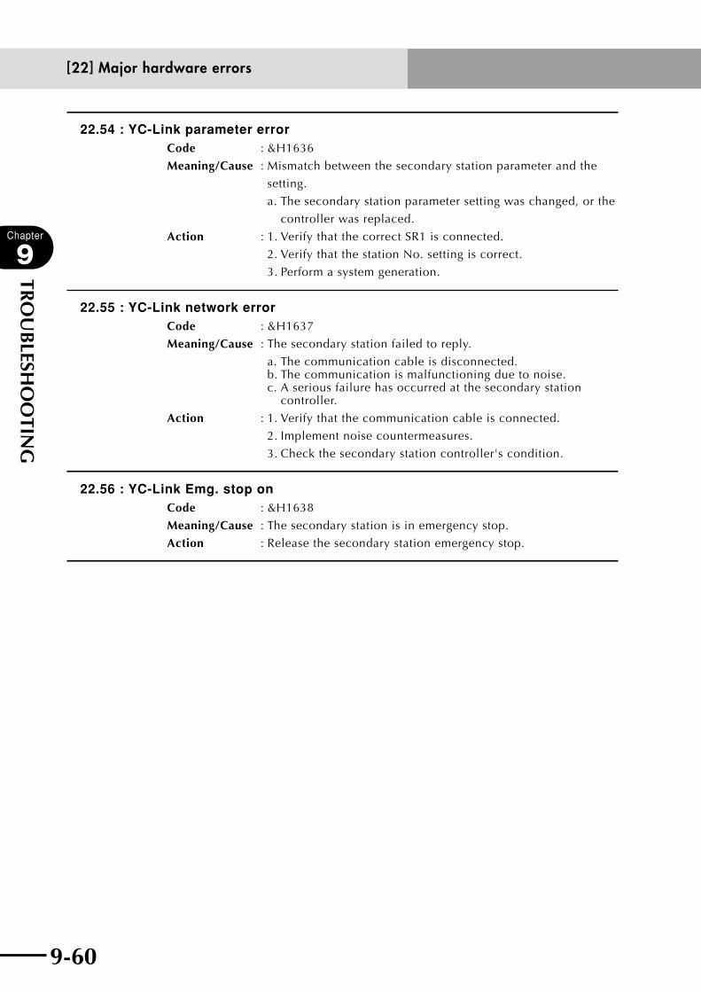
9-60
Chapter
9
TRO
UB
LESHO
OTIN
G
9-61
22.54 : YC-Link parameter errorCode : &H1636
Meaning/Cause : Mismatch between the secondary station parameter and the
setting.
a. The secondary station parameter setting was changed, or the
controller was replaced.
Action : 1. Verify that the correct SR1 is connected.
2. Verify that the station No. setting is correct.
3. Perform a system generation.
22.55 : YC-Link network errorCode : &H1637
Meaning/Cause : The secondary station failed to reply.
a. The communication cable is disconnected. b. The communication is malfunctioning due to noise. c. A serious failure has occurred at the secondary station
controller.
Action : 1. Verify that the communication cable is connected.
2. Implement noise countermeasures.
3. Check the secondary station controller's condition.
22.56 : YC-Link Emg. stop onCode : &H1638
Meaning/Cause : The secondary station is in emergency stop.
Action : Release the secondary station emergency stop.
[22] Major hardware errors

9-60 9-61
Chapter
9
TRO
UB
LESHO
OTIN
G
1.2 RPB Error MessagesWhen a hardware error or a software error occurs in the RPB, the following messages are
highlighted (shown with reversed background) on the guideline of the lowest line of the
screen.
RPB TRAP!!
Contents : Undefined operation code was executed.
Cause : A hardware error occurred.
Action : Replace the RPB.
RPB Receive Error!! (Data Register Full)
Contents : Data receive register is full.
Cause : A hardware error occurred.
Action : Replace the RPB.
RPB Receive Error!! (Over Run Error)
Contents : An overrun occurred while receiving data.
Cause : a. Malfunction occurred due to noise.
b. The cable is broken or disconnected.
c. The connector is not making contact.
Action : 1. Separate equipment away from noise source.
2. Replace the RPB cable.
3. Replace the RPB.
RPB Receive Error!! (Parity Error)
Contents : Parity error occurred during communication.
Cause : a. Malfunction occurred due to noise.
b. The cable is broken or disconnected.
c. The connector is not making contact.
Action : 1. Separate equipment away from noise source.
2. Replace the RPB cable.
RPB Receive Error!! (Framing Error)
Contents : Framing error occurred during communication.
Cause : Malfunction occurred due to noise.
Action : Separate equipment away from noise source.
RPB Receive Error!! (Buffer Overflow)
Contents : Remaining area in receive buffer fell below 1% during
communications.
Cause : a. Large amount of data was sent from the controller.
b. Communication control error.
Action : 1. Replace the RPB.
2. Replace the controller.
1. Error Messages
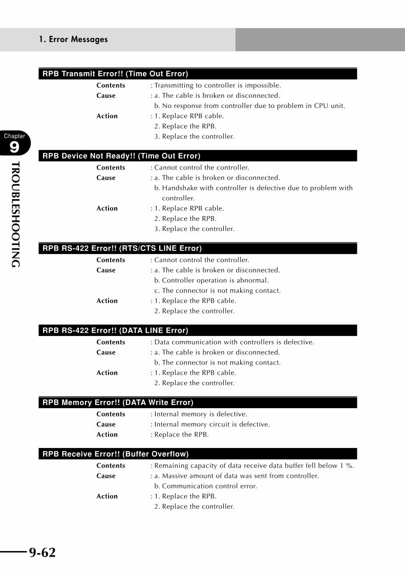
9-62
Chapter
9
TRO
UB
LESHO
OTIN
G
9-63
RPB Transmit Error!! (Time Out Error)
Contents : Transmitting to controller is impossible.
Cause : a. The cable is broken or disconnected.
b. No response from controller due to problem in CPU unit.
Action : 1. Replace RPB cable.
2. Replace the RPB.
3. Replace the controller.
RPB Device Not Ready!! (Time Out Error)
Contents : Cannot control the controller.
Cause : a. The cable is broken or disconnected.
b. Handshake with controller is defective due to problem with
controller.
Action : 1. Replace RPB cable.
2. Replace the RPB.
3. Replace the controller.
RPB RS-422 Error!! (RTS/CTS LINE Error)
Contents : Cannot control the controller.
Cause : a. The cable is broken or disconnected.
b. Controller operation is abnormal.
c. The connector is not making contact.
Action : 1. Replace the RPB cable.
2. Replace the controller.
RPB RS-422 Error!! (DATA LINE Error)
Contents : Data communication with controllers is defective.
Cause : a. The cable is broken or disconnected.
b. The connector is not making contact.
Action : 1. Replace the RPB cable.
2. Replace the controller.
RPB Memory Error!! (DATA Write Error)
Contents : Internal memory is defective.
Cause : Internal memory circuit is defective.
Action : Replace the RPB.
RPB Receive Error!! (Buffer Overflow)
Contents : Remaining capacity of data receive data buffer fell below 1 %.
Cause : a. Massive amount of data was sent from controller.
b. Communication control error.
Action : 1. Replace the RPB.
2. Replace the controller.
1. Error Messages
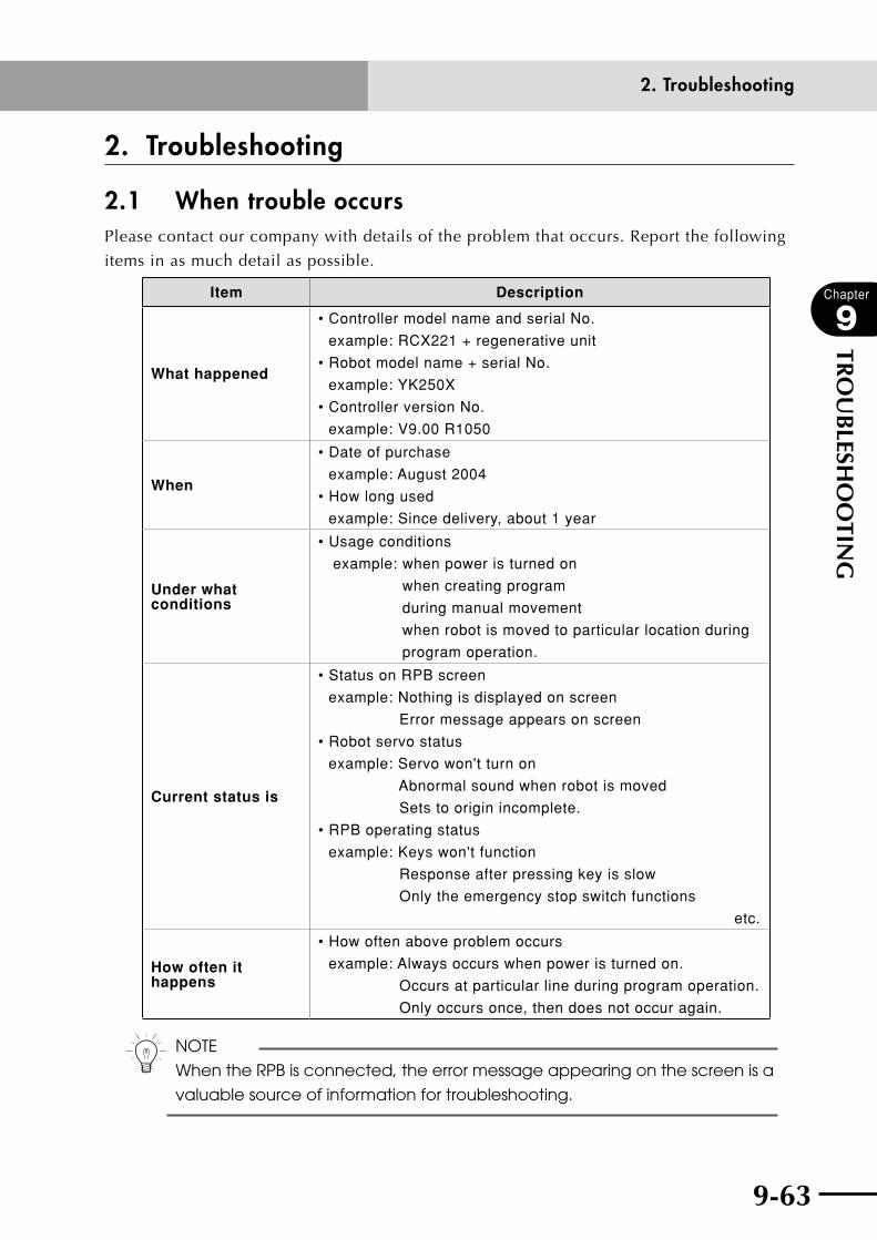
9-62 9-63
Chapter
9
TRO
UB
LESHO
OTIN
G
2. Troubleshooting
2.1 When trouble occursPlease contact our company with details of the problem that occurs. Report the following
items in as much detail as possible.
Item Description
What happened
• Controller model name and serial No.
example: RCX221 + regenerative unit
• Robot model name + serial No.
example: YK250X
• Controller version No.
example: V9.00 R1050
When
• Date of purchase
example: August 2004
• How long used
example: Since delivery, about 1 year
Under what conditions
• Usage conditions
example: when power is turned on
when creating program
during manual movement
when robot is moved to particular location during
program operation.
Current status is
• Status on RPB screen
example: Nothing is displayed on screen
Error message appears on screen
• Robot servo status
example: Servo won't turn on
Abnormal sound when robot is moved
Sets to origin incomplete.
• RPB operating status
example: Keys won't function
Response after pressing key is slow
Only the emergency stop switch functions
etc.
How often it happens
• How often above problem occurs
example: Always occurs when power is turned on.
Occurs at particular line during program operation.
Only occurs once, then does not occur again.
n NOTE
When the RPB is connected, the error message appearing on the screen is a
valuable source of information for troubleshooting.
2. Troubleshooting

9-64
Chapter
9
TRO
UB
LESHO
OTIN
G
9-65
2.2 Acquiring error informationError history (log) information is stored inside the robot controller. The following two
methods are available for checking this information.
2.2.1 Acquiring information from the RPB
[Procedure]
1) Press (DIAGNOS) in "SYSTEM" mode.
2) To check controller error status, press (DIAGNOS).
A maximum of 5 error histories are displayed.
3) To check a particular error history, press (HISTORY).
A maximum of 500 error histories can be checked.
2.2.2 Acquiring information from the RS-232C
[Procedure]
1) Connect the robot controller to the PC with the RS-232C cable.
2) Set the communication conditions.
3) Send "@READ LOG" from the PC to receive the internal error history in the robot
controller.
A maximum of 500 error histories can be checked.
2. Troubleshooting

9-64 9-65
Chapter
9
TRO
UB
LESHO
OTIN
G
2.3 Troubleshooting checkpoints1. Installation and power supply
Symptom Possible cause Check items Corrective action
1 Controller won't turn on even with power supplied.
• Power not supplied.
• Problem in controller internal power.
• Check power input terminal connection (L/N/L1/N1/FG).
• Check power input terminal voltage (L/N/L1/N1/FG).
• Check if "RDY" LED on front panel is lit.
• Connect power input terminal correctly.
• Supply rated power supply voltage.
• Replace the controller.
2 Controller turns on but no RPB display.
• RPB not connected.
• Wrong RPB connection.
• RPB malfunctioning.
• Problem in controller internal power supply.
• Check RPB connector.
• Check how RPB connector is inserted.
• Replace RPB and check operation.
• Plug in RPB connector correctly.
• Replace the RPB.
• Replace the controller.
3 Controller turns on but "ERR" LED on front panel lights up.
• Now in emergency stop.
• Connect the RPB and check the error history.
• Check DI00 (Emergency stop ready signal) on RPB screen.
• Release RPB emergency stop switch.
• Insert RPB connector.
• Connect the emergency stop terminal of SAFETY connector.
• Error of error group No. 17 occurred.
• Connect the RPB and check the error history.
• Check the axis from the error information.
• Check the cause from the error information.
• Eliminate the cause of the error.
• Error of error group No. 21, 22 occurred.
• Connect the RPB and check the error history.
• Check the cause from the error information.
• Eliminate the cause of the error.
2. Troubleshooting
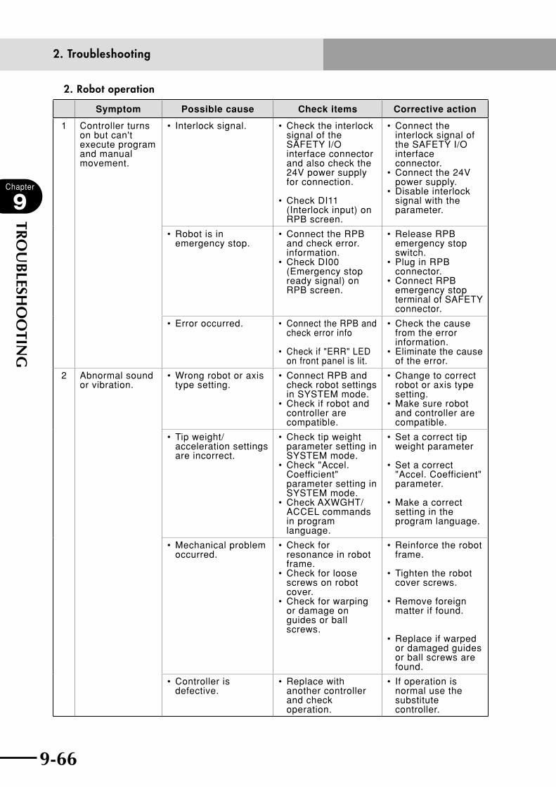
9-66
Chapter
9
TRO
UB
LESHO
OTIN
G
9-67
2. Robot operation
Symptom Possible cause Check items Corrective action
1 Controller turns on but can't execute program and manual movement.
• Interlock signal. • Check the interlock signal of the SAFETY I/O interface connector and also check the 24V power supply for connection.
• Check DI11 (Interlock input) on RPB screen.
• Connect the interlock signal of the SAFETY I/O interface connector.
• Connect the 24V power supply.
• Disable interlock signal with the parameter.
• Robot is in emergency stop.
• Connect the RPB and check error. information.
• Check DI00 (Emergency stop ready signal) on RPB screen.
• Release RPB emergency stop switch.
• Plug in RPB connector.
• Connect RPB emergency stop terminal of SAFETY connector.
• Error occurred. • Connect the RPB and check error info
• Check if "ERR" LED on front panel is lit.
• Check the cause from the error information.
• Eliminate the cause of the error.
2 Abnormal sound or vibration.
• Wrong robot or axis type setting.
• Connect RPB and check robot settings in SYSTEM mode.
• Check if robot and controller are compatible.
• Change to correct robot or axis type setting.
• Make sure robot and controller are compatible.
• Tip weight/ acceleration settings are incorrect.
• Check tip weight parameter setting in SYSTEM mode.
• Check "Accel. Coefficient" parameter setting in SYSTEM mode.
• Check AXWGHT/ACCEL commands in program language.
• Set a correct tip weight parameter
• Set a correct "Accel. Coefficient" parameter.
• Make a correct setting in the program language.
• Mechanical problem occurred.
• Check for resonance in robot frame.
• Check for loose screws on robot cover.
• Check for warping or damage on guides or ball screws.
• Reinforce the robot frame.
• Tighten the robot cover screws.
• Remove foreign matter if found.
• Replace if warped or damaged guides or ball screws are found.
• Controller is defective.
• Replace with another controller and check operation.
• If operation is normal use the substitute controller.
2. Troubleshooting

9-66 9-67
Chapter
9
TRO
UB
LESHO
OTIN
G
Symptom Possible cause Check items Corrective action
3 Position deviation occurred.
• There are 2 main types of position deviation.
1.Electrical position deviation
2.Mechanical position deviation In case 1, if position deviation occurs, you can perform return-to-origin and return to original position. In case 2, you cannot return to original position.
• Position sensor device is defective.
• Cable is defective.
• Move axis in emergency stop and check the pulse count.
• Replace motor if count is incorrect.
• Replace cable if found to be defective.
• Position detection error due to noise.
• Check grounding of robot and controller.
• Check robot periphery for noise.
• Check for noise sources around robot I/O cable.
• Ground the robot and controller.
• Isolate from noise sources around robot.
• Isolate from noise sources around robot I/O cable.
• Mechanical error occurred.
• Check the belt tension
• Check for warping or damage on guides or ball screws.
• Adjust to correct tension if necessary.
• Remove foreign matter if found.
• Replace guides or ball screws if warping or damage is found.
• Controller is defective.
• Replace with another controller and check operation.
• If operation is normal use the substitute controller.
2. Troubleshooting

9-68
Chapter
9
TRO
UB
LESHO
OTIN
G
3. I/O operation
Symptom Possible cause Check items Corrective action
1 Won't operate even when dedicated input signal is supplied.
• No DC24V supply. • Check that DC 24V is supplied from I/O interface connector (STD.DIO).
• Supply DC 24V.
• Problem in signal connection.
• Check wiring on I/O interface connector (STD.DIO).
• Make the correct wiring on I/O interface connector (STD.DIO).
• Error has occurred. • Connect RPB and check robot settings in SYSTEM mode.
• Check if "ERR" LED is lit on front of controller.
• Check the cause from the error information.
• Eliminate the cause of the error.
2 No output of dedicated output signal.
• No DC24V supply. • Check that DC 24V is supplied from I/O interface connector (STD.DIO).
• Supply DC 24V.
• Problem in signal connection.
• Check wiring on I/O interface connector (STD.DIO).
• Make the correct wiring on I/O interface connector (STD.DIO).
• Error has occurred. • Connect the RPB and check robot settings in SYSTEM mode.
• Check if "ERR" LED is lit on front of controller.
• Check the cause from the error information.
• Eliminate the cause of the error.
3 No output of general-purpose I/O signal.
• No DC24V supply. • Check that DC 24V is supplied from I/O interface connector (STD.DIO).
• Check that DC 24V is supplied for I/O interface connector (OP.DIO).
• Supply DC 24V.
• Problem in signal connection.
• Check wiring on I/O interface connector (STD.DIO).
• Check wiring on I/O interface connector (OP.DIO).
• Make the correct wiring on I/O interface connector (STD.DIO).
• Make the correct wiring on I/O interface connector (OP.DIO).
• Error in I/O interface (OP.DIO) setting.
• Check the I/O interface (OP.DIO) setting on the DIP switch.
• Make the correct I/O interface (OP.DIO) setting.
• Error has occurred. • Connect the RPB and check the error information.
• Check if "ERR" LED is lit on front of controller.
• Check the cause from the error information.
• Eliminate the cause of the error.
2. Troubleshooting


All rights reserved. No part of this publication may be reproduced in any form without the permission of YAMAHA MOTOR CO., LTD. Information furnished by YAMAHA in this manual is believed to be reliable. However, no responsibility is assumed for possible inaccuracies or omissions. If you find any part unclear in this manual, please contact your distributor.
2-axis Robot Controller
User's Manual
YAMAHA MOTOR CO., LTD. IM Operations
RCX221
Revision record
Manual version Issue date Description
Ver. 2.06 Dec. 2009 The address and other information were added to the front cover.
Ver. 2.07 Mar. 2010 Addition and correction of explanations in "Chapter 1 Using the Robot Safely". Addition of explanations on installation location. Addition and correction of specification table and external view in "Chapter 8 Specifications". Clerical error corrections, etc.
Ver. 2.08 Aug. 2010 Communication mode parameter was added to Ethernet option board parameter. Addition of Installing a surge absorber in Chapter 3 "4. Connecting to the power". Clerical error corrections, etc.
Ver. 2.09 Jan. 2011 The description regarding "Warranty" was changed. Clerical error corrections.
Ver. 2.10 Jun. 2011 Addition of new parameters to Other parameters.
Ver. 2.11 Dec. 2011 Error messages such as "[19] YC-Link (SR1) related error" were added or changed. Return-to-origin timing chart was corrected. Descriptions of "4.1 Connection example" and "4.7 Installing an electromagnetic contactor" in " 4. Connecting to the power" of Chapter 3 were added or corrected. A parameter (manual movement mode) was added to Other parameters, and so forth.
Ver. 2.12 Jul. 2012 A parameter (DO cond. on PGM reset / RESCDO) was added to Other parameters. The description regarding "Warranty" was changed. Clerical error corrections, etc.
Jul. 2012Ver. 2.12This manual is based on Ver. 2.12 of Japanese manual.


http://www.yamaha-motor.co.jp/global/industrial/robot/
Instruction manuals can be downloaded from our company website. Please use the following for more detailed information.
YAMAHA MOTOR CO., LTD.
IM Operations
882 Soude, Nakaku, Hamamatsu, Shizuoka, 435-0054, JapanTel. 81-53-460-6103 Fax. 81-53-460-6811
Top Related