


Languages
Pages
Legal

0
Wireless Outdoor
Access Point / Client Bridge
M5000
User Manual Version : V1.0
1
Table of Contents
1 PRODUCT OVERVIEW ........................................................................................................................................................... 3
1.1 FEATURE ......................................................................................................................................................................... 3
1.2 BENEFITS ........................................................................................................................................................................ 5
1.3 PACKAGE CONTENTS ......................................................................................................................................................... 6
1.4 SYSTEM REQUIREMENT ..................................................................................................................................................... 6
1.5 HARDWARE OVERVIEW ..................................................................................................................................................... 6
2 M5000 MULTI-FUNCTION INSTRUCTION GUIDE .................................................................................................................. 8
2.1 ACCESS POINT ................................................................................................................................................................. 8
2.2 ACCESS POINT WITH WDS FUNCTION .................................................................................................................................. 8
2.3 CLIENT BRIDGE ................................................................................................................................................................ 9
2.4 WDS BRIDGE .................................................................................................................................................................. 9
2.5 CLIENT ROUTER ............................................................................................................................................................. 10
2.6 MESH .......................................................................................................................................................................... 10
3 COMPUTER SETTINGS ........................................................................................................................................................ 12
3.1 ASSIGN A STATIC IP ......................................................................................................................................................... 12
3.2 LOGGING METHOD ......................................................................................................................................................... 13
4 WIRELESS SETTINGS ........................................................................................................................................................... 14
4.1 SWITCHING OPERATION MODE (SYSTEM → SYSTEM PROPERTIES) ......................................................................................... 14
4.2 WIRELESS SETTINGS ....................................................................................................................................................... 15
4.2.1 Access Point Mode → Wireless Network ...................................................................................................... 15
4.2.2 Client Bridge Mode → Wireless Network ..................................................................................................... 17
4.2.3 WDS Bridge Mode → Wireless Network ...................................................................................................... 18
4.2.4 Client Router Mode → Wireless Network ..................................................................................................... 20
4.2.5 Mesh Mode → Wireless Network ................................................................................................................. 21
4.3 WIRELESS SECURITY SETTINGS .......................................................................................................................................... 24
4.3.1 WEP................................................................................................................................................................. 24
4.3.2 WPA-PSK ......................................................................................................................................................... 25
4.3.3 WPA2-PSK ....................................................................................................................................................... 25
4.3.4 WPA-PSK Mixed ............................................................................................................................................... 26
4.3.5 WPA ................................................................................................................................................................ 27
4.3.6 WPA2 .............................................................................................................................................................. 28
4.3.7 WPA Mixed ...................................................................................................................................................... 29
4.3.8 Radius Accounting ........................................................................................................................................... 30
4.4 WIRELESS → WIRELESS ADVANCED SETTINGS ................................................................................................................... 31
4.5 WIRELESS → WIRELESS MAC FILTER ............................................................................................................................... 33
2
4.6 WIRELESS → WDS LINK SETTINGS .................................................................................................................................. 34
5 LAN SETTINGS ..................................................................................................................................................................... 35
5.1 SYSTEM → IP SETTINGS ................................................................................................................................................ 35
5.2 SYSTEM → SPANNING TREE SETTINGS .............................................................................................................................. 36
6 ROUTER SETTINGS .............................................................................................................................................................. 37
6.1 ROUTER → WAN SETTINGS .......................................................................................................................................... 37
6.1.1 WAN Settings → Static IP ............................................................................................................................. 37
6.1.2 WAN Settings → DHCP (Dynamic IP) ............................................................................................................ 40
6.1.3 WAN Settings → PPPoE (Point-to-Point Protocol over Ethernet) .................................................................. 42
6.1.4 WAN Settings → PPTP (Point-to-Point Tunneling Protocol) .......................................................................... 44
6.2 ROUTER → LAN SETTINGS ............................................................................................................................................ 46
6.3 ROUTER → VPN PASS THROUGH .................................................................................................................................... 47
6.4 ROUTER → PORT FORWARDING ..................................................................................................................................... 48
7 INFORMATION STATUS ....................................................................................................................................................... 49
7.1 STATUS → MAIN ......................................................................................................................................................... 49
7.2 STATUS → WIRELESS CLIENT LIST .................................................................................................................................... 51
7.3 STATUS → SYSTEM LOG ................................................................................................................................................. 52
7.4 STATUS → WDS LINK STATUS ........................................................................................................................................ 53
7.5 STATUS → CONNECTION STATUS ..................................................................................................................................... 54
7.6 STATUS → DHCP CLIENT TABLE...................................................................................................................................... 55
8 MANAGEMENT SETTINGS .................................................................................................................................................. 56
8.1 MANAGEMENT → ADMINISTRATION ............................................................................................................................... 56
8.2 MANAGEMENT → MANAGEMENT VLAN ......................................................................................................................... 58
8.3 MANAGEMENT → SNMP SETTINGS ............................................................................................................................... 59
8.4 MANAGEMENT → BACKUP/RESTORE SETTINGS ................................................................................................................. 60
8.5 MANAGEMENT → FIRMWARE UPGRADE .......................................................................................................................... 61
8.6 MANAGEMENT → TIME SETTINGS .................................................................................................................................. 62
8.7 MANAGEMENT → LOG ................................................................................................................................................. 63
8.8 MANAGEMENT → DIAGNOSTICS ..................................................................................................................................... 64
9 NETWORK CONFIGURATION EXAMPLE .............................................................................................................................. 65
9.1 ACCESS POINT ............................................................................................................................................................... 65
9.2 CLIENT BRIDGE MODE .................................................................................................................................................... 66
9.3 WDS BRIDGE MODE ...................................................................................................................................................... 66
9.4 CLIENT ROUTER ............................................................................................................................................................. 67
9.5 MESH .......................................................................................................................................................................... 68
10 VLAN CONFIGURATION GUIDE ......................................................................................................................................... 71
3
APPENDIX A – FCC INTERFERENCE STATEMENT .................................................................................................................... 75
1 Product Overview
Thank you for using M5000. It is a powerful, enhanced, enterprise scale product with 5+1
multi-functions Access Point, Access Point with WDS function, Client Bridge, WDS Bridge, Client
Router, and Mesh.
M5000 is easily to install almost anywhere with Power over Ethernet for quick outdoor installation.
External N-type antenna provides better wireless signal quality and the antenna is upgradeable.
M5000 uses 5G band wireless signals to avoid interference of most digital signal such as mobile
phone.
M5000 can manage power level control, Narrow bandwidth selection, Traffic shaping and Real-time
RSSI indicator. M5000 is fully support of security encryption including Wi-Fi Protected Access
(WPA-PSK/WPA2-PSK), 64/128/152-bit WEP Encryption and IEEE 802.1x with RADIUS Accounting.
1.1 Feature
The following list describes the design of the M5000 made possible through the power and flexibility
of wireless LANs:
a) Difficult-to-wire environments
There are many situations where wires cannot be laid easily. Historic buildings, older
buildings, open areas and across busy streets make the installation of LANs either
impossible or very expensive.
b) Temporary workgroups
Consider situations in parks, athletic arenas, exhibition centers, disaster-recovery,
temporary offices and construction sites where one wants a temporary WLAN established
and removed.
c) The ability to access real-time information
Doctors/nurses, point-of-sale employees, and warehouse workers can access real-time
information while dealing with patients, serving customers and processing information.
d) Frequently changed environments
4
Show rooms, meeting rooms, retail stores, and manufacturing sites where frequently
rearrange the workplace.
e) Wireless extensions to Ethernet networks
Network managers in dynamic environments can minimize the overhead caused by moves,
extensions to networks, and other changes with wireless LANs.
f) Wired LAN backup
Network managers implement wireless LANs to provide backup for mission-critical
applications running on wired networks.
g) Training/Educational facilities
Training sites at corporations and students at universities use wireless connectivity to ease
access to information, information exchanges, and learning.
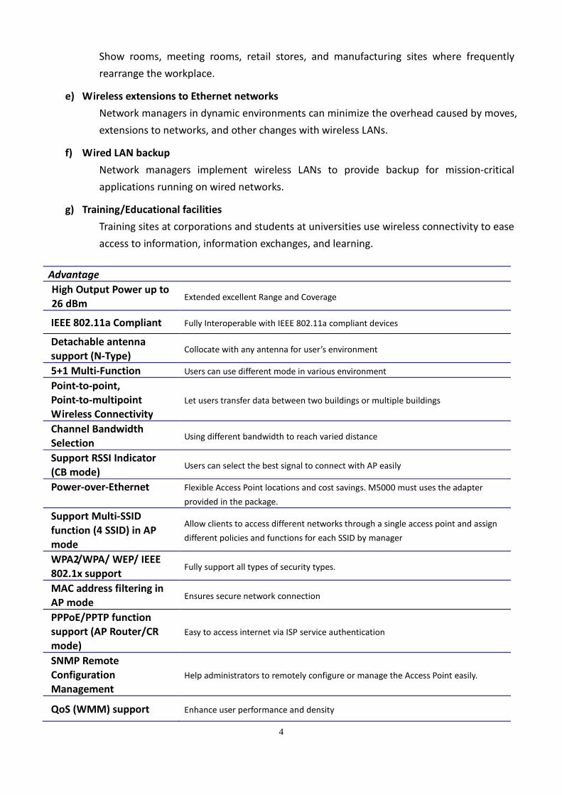
Advantage
High Output Power up to
26 dBm Extended excellent Range and Coverage
IEEE 802.11a Compliant Fully Interoperable with IEEE 802.11a compliant devices
Detachable antenna
support (N-Type) Collocate with any antenna for user’s environment
5+1 Multi-Function Users can use different mode in various environment
Point-to-point,
Point-to-multipoint
Wireless Connectivity
Let users transfer data between two buildings or multiple buildings
Channel Bandwidth
Selection Using different bandwidth to reach varied distance
Support RSSI Indicator
(CB mode) Users can select the best signal to connect with AP easily
Power-over-Ethernet Flexible Access Point locations and cost savings. M5000 must uses the adapter
provided in the package.
Support Multi-SSID
function (4 SSID) in AP
mode
Allow clients to access different networks through a single access point and assign
different policies and functions for each SSID by manager
WPA2/WPA/ WEP/ IEEE
802.1x support Fully support all types of security types.
MAC address filtering in
AP mode Ensures secure network connection
PPPoE/PPTP function
support (AP Router/CR
mode)
Easy to access internet via ISP service authentication
SNMP Remote
Configuration
Management
Help administrators to remotely configure or manage the Access Point easily.
QoS (WMM) support Enhance user performance and density
5
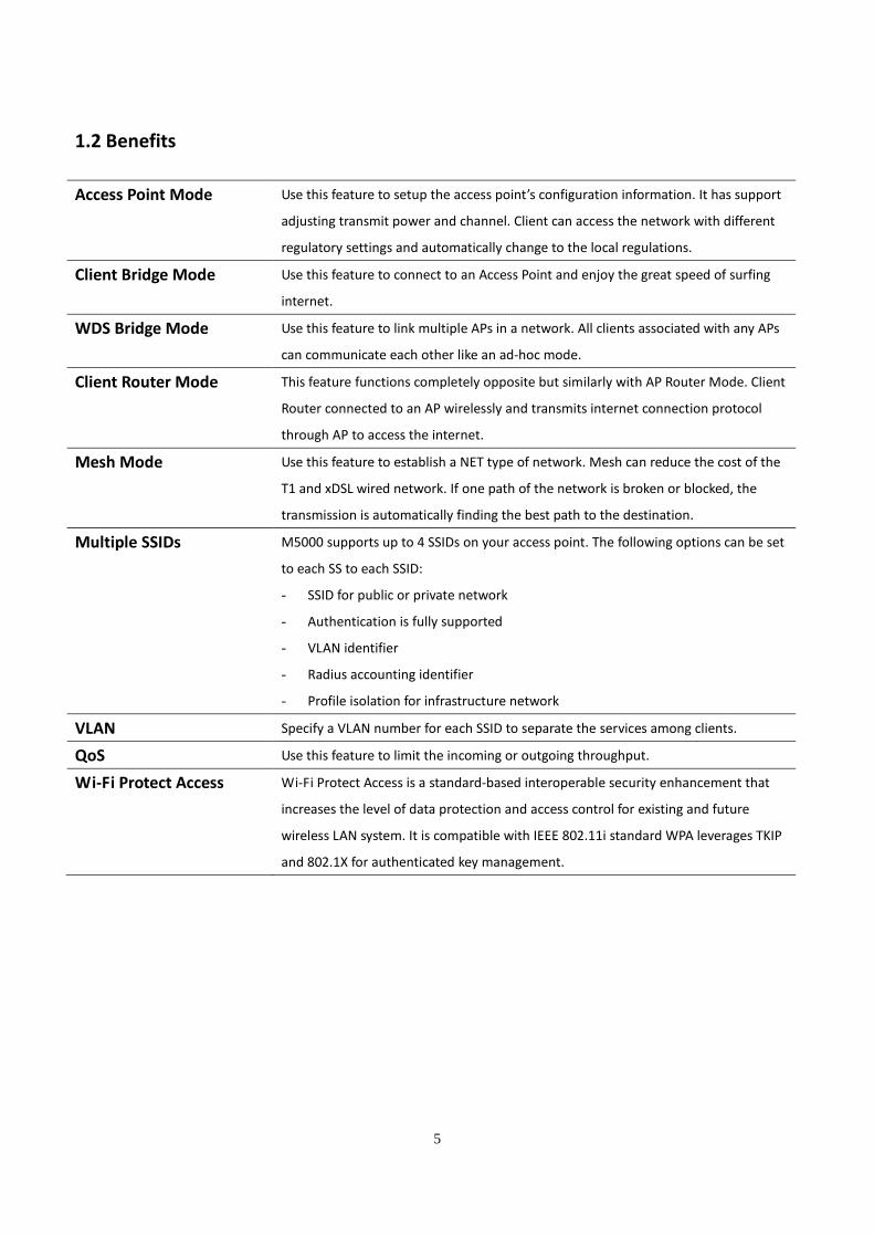
1.2 Benefits
Access Point Mode Use this feature to setup the access point’s configuration information. It has support
adjusting transmit power and channel. Client can access the network with different
regulatory settings and automatically change to the local regulations.
Client Bridge Mode Use this feature to connect to an Access Point and enjoy the great speed of surfing
internet.
WDS Bridge Mode Use this feature to link multiple APs in a network. All clients associated with any APs
can communicate each other like an ad-hoc mode.
Client Router Mode This feature functions completely opposite but similarly with AP Router Mode. Client
Router connected to an AP wirelessly and transmits internet connection protocol
through AP to access the internet.
Mesh Mode Use this feature to establish a NET type of network. Mesh can reduce the cost of the
T1 and xDSL wired network. If one path of the network is broken or blocked, the
transmission is automatically finding the best path to the destination.
Multiple SSIDs M5000 supports up to 4 SSIDs on your access point. The following options can be set
to each SS to each SSID:
- SSID for public or private network
- Authentication is fully supported
- VLAN identifier
- Radius accounting identifier
- Profile isolation for infrastructure network
VLAN Specify a VLAN number for each SSID to separate the services among clients.
QoS Use this feature to limit the incoming or outgoing throughput.
Wi-Fi Protect Access Wi-Fi Protect Access is a standard-based interoperable security enhancement that
increases the level of data protection and access control for existing and future
wireless LAN system. It is compatible with IEEE 802.11i standard WPA leverages TKIP
and 802.1X for authenticated key management.
6
1.3 Package Contents
Open the package carefully, and make sure that none of the items listed below are missing. Do not
discard the packing materials, in case of return; the unit must be shipped in its original package.
� 1* Wireless Outdoor Access Point / Client Bridge (M5000)
� 1* 24V/1A Power Adapter
� 1* Ethernet Cable
� 1* QIG
� 1* CD (User Manual)
� 1* 5dBi Dipole Antennas
Auction: Using other Power Adapter than the one included with M5000 may cause damage of the
device.
1.4 System Requirement
The following conditions are the minimum system requirement.
� A computer with an Ethernet interface and operating under Windows XP, Vista, 7 or Linux.
� Internet Browser that supports HTTP and JavaScript.
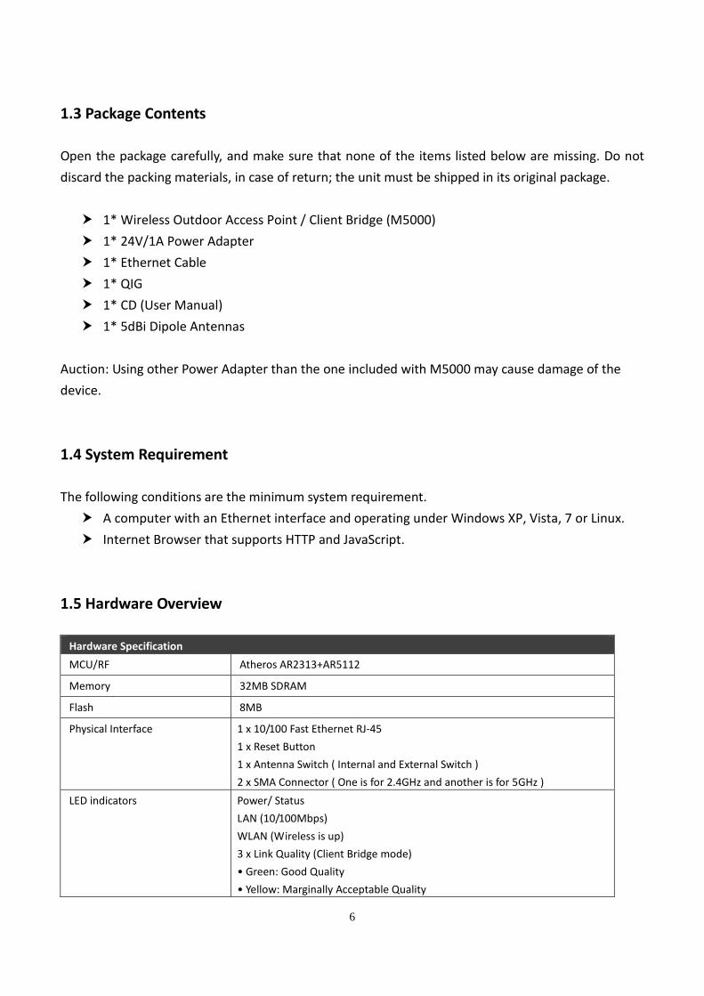
1.5 Hardware Overview
Hardware Specification
MCU/RF Atheros AR2313+AR5112
Memory 32MB SDRAM
Flash 8MB
Physical Interface 1 x 10/100 Fast Ethernet RJ-45
1 x Reset Button
1 x Antenna Switch ( Internal and External Switch )
2 x SMA Connector ( One is for 2.4GHz and another is for 5GHz )
LED indicators Power/ Status
LAN (10/100Mbps)
WLAN (Wireless is up)
3 x Link Quality (Client Bridge mode)
• Green: Good Quality
• Yellow: Marginally Acceptable Quality

7
• Red: Bad Quality
Power Requirements Active Ethernet (Power over Ethernet) Proprietary PoE design
Power Adapter 24V / 1A DC
Regulation Certifications FCC Part 15C/15B/15E, EN301 893, EN 300 328, EN 301 489-1/-17, EN60950,
IC Certification
8
2 M5000 Multi-Function Instruction Guide
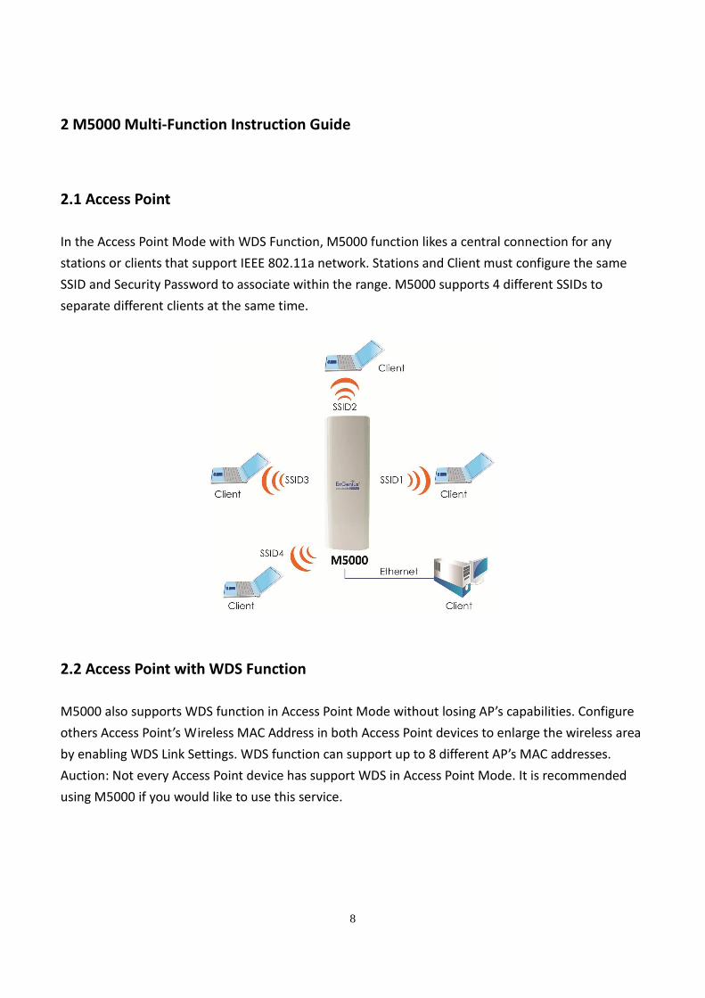
2.1 Access Point
In the Access Point Mode with WDS Function, M5000 function likes a central connection for any
stations or clients that support IEEE 802.11a network. Stations and Client must configure the same
SSID and Security Password to associate within the range. M5000 supports 4 different SSIDs to
separate different clients at the same time.
2.2 Access Point with WDS Function
M5000 also supports WDS function in Access Point Mode without losing AP’s capabilities. Configure
others Access Point’s Wireless MAC Address in both Access Point devices to enlarge the wireless area
by enabling WDS Link Settings. WDS function can support up to 8 different AP’s MAC addresses.
Auction: Not every Access Point device has support WDS in Access Point Mode. It is recommended
using M5000 if you would like to use this service.
9
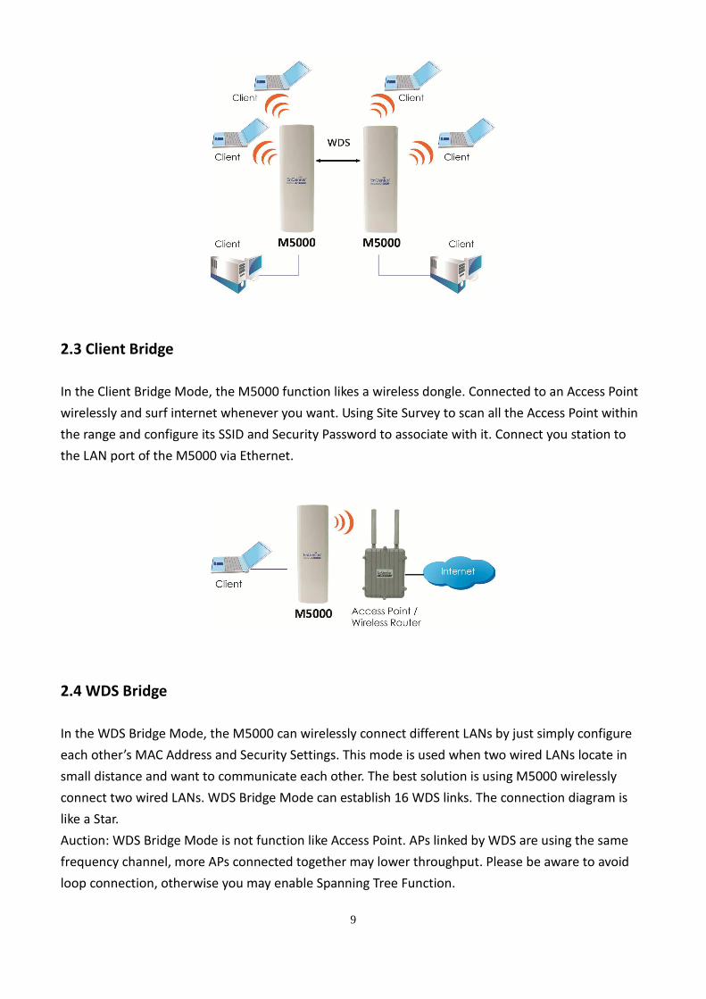
2.3 Client Bridge
In the Client Bridge Mode, the M5000 function likes a wireless dongle. Connected to an Access Point
wirelessly and surf internet whenever you want. Using Site Survey to scan all the Access Point within
the range and configure its SSID and Security Password to associate with it. Connect you station to
the LAN port of the M5000 via Ethernet.
2.4 WDS Bridge
In the WDS Bridge Mode, the M5000 can wirelessly connect different LANs by just simply configure
each other’s MAC Address and Security Settings. This mode is used when two wired LANs locate in
small distance and want to communicate each other. The best solution is using M5000 wirelessly
connect two wired LANs. WDS Bridge Mode can establish 16 WDS links. The connection diagram is
like a Star.
Auction: WDS Bridge Mode is not function like Access Point. APs linked by WDS are using the same
frequency channel, more APs connected together may lower throughput. Please be aware to avoid
loop connection, otherwise you may enable Spanning Tree Function.
10
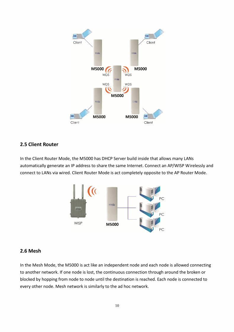
2.5 Client Router
In the Client Router Mode, the M5000 has DHCP Server build inside that allows many LANs
automatically generate an IP address to share the same Internet. Connect an AP/WISP Wirelessly and
connect to LANs via wired. Client Router Mode is act completely opposite to the AP Router Mode.
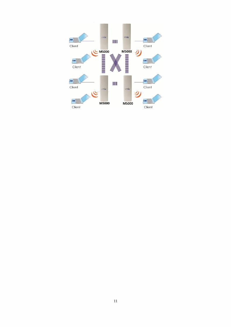
2.6 Mesh
In the Mesh Mode, the M5000 is act like an independent node and each node is allowed connecting
to another network. If one node is lost, the continuous connection through around the broken or
blocked by hopping from node to node until the destination is reached. Each node is connected to
every other node. Mesh network is similarly to the ad hoc network.
11
12
3 Computer Settings
3.1 Assign a Static IP
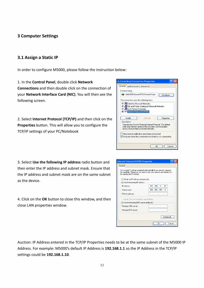
In order to configure M5000, please follow the instruction below:
1. In the Control Panel, double click Network
Connections and then double click on the connection of
your Network Interface Card (NIC). You will then see the
following screen.
2. Select Internet Protocol (TCP/IP) and then click on the
Properties button. This will allow you to configure the
TCP/IP settings of your PC/Notebook
3. Select Use the following IP address radio button and
then enter the IP address and subnet mask. Ensure that
the IP address and subnet mask are on the same subnet
as the device.
4. Click on the OK button to close this window, and then
close LAN properties window.
Auction: IP Address entered in the TCP/IP Properties needs to be at the same subnet of the M5000 IP
Address. For example: M5000’s default IP Address is 192.168.1.1 so the IP Address in the TCP/IP
settings could be 192.168.1.10.
13
3.2 Logging Method
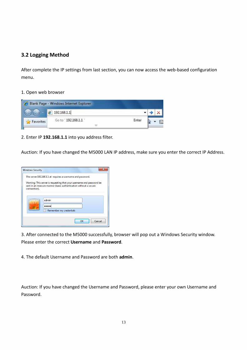
After complete the IP settings from last section, you can now access the web-based configuration
menu.
1. Open web browser
2. Enter IP 192.168.1.1 into you address filter.
Auction: If you have changed the M5000 LAN IP address, make sure you enter the correct IP Address.
3. After connected to the M5000 successfully, browser will pop out a Windows Security window.
Please enter the correct Username and Password.
4. The default Username and Password are both admin.
Auction: If you have changed the Username and Password, please enter your own Username and
Password.
14
4 Wireless Settings
4.1 Switching Operation Mode (System → System Properties)
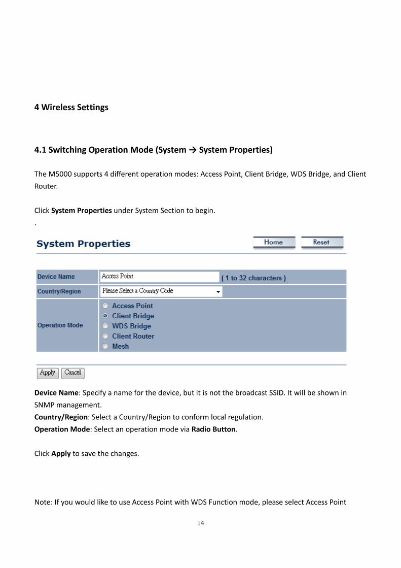
The M5000 supports 4 different operation modes: Access Point, Client Bridge, WDS Bridge, and Client
Router.
Click System Properties under System Section to begin.
.
Device Name: Specify a name for the device, but it is not the broadcast SSID. It will be shown in
SNMP management.
Country/Region: Select a Country/Region to conform local regulation.
Operation Mode: Select an operation mode via Radio Button.
Click Apply to save the changes.
Note: If you would like to use Access Point with WDS Function mode, please select Access Point
15
Mode and then enable WDS Link Settings function.
4.2 Wireless Settings
4.2.1 Access Point Mode → Wireless Network
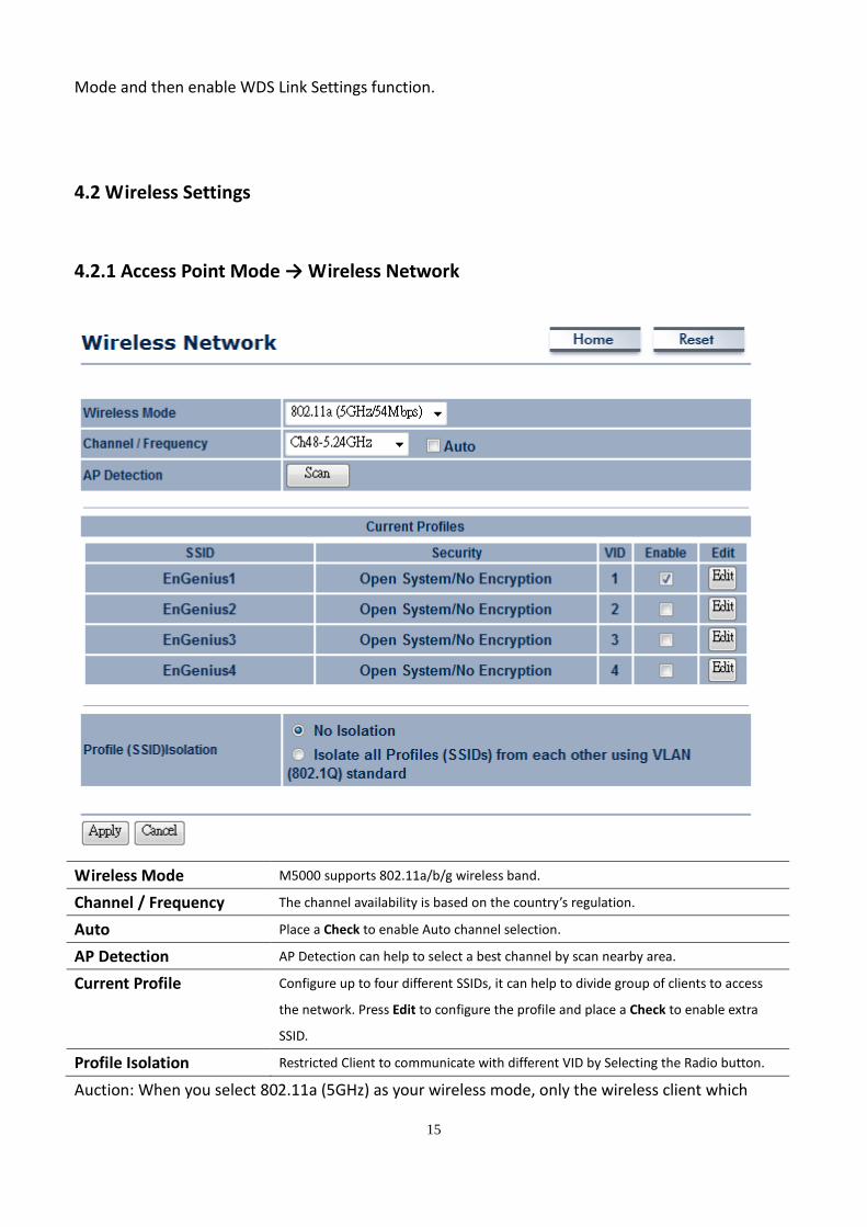
Wireless Mode M5000 supports 802.11a/b/g wireless band.
Channel / Frequency The channel availability is based on the country’s regulation.
Auto Place a Check to enable Auto channel selection.
AP Detection AP Detection can help to select a best channel by scan nearby area.
Current Profile Configure up to four different SSIDs, it can help to divide group of clients to access
the network. Press Edit to configure the profile and place a Check to enable extra
SSID.
Profile Isolation Restricted Client to communicate with different VID by Selecting the Radio button.
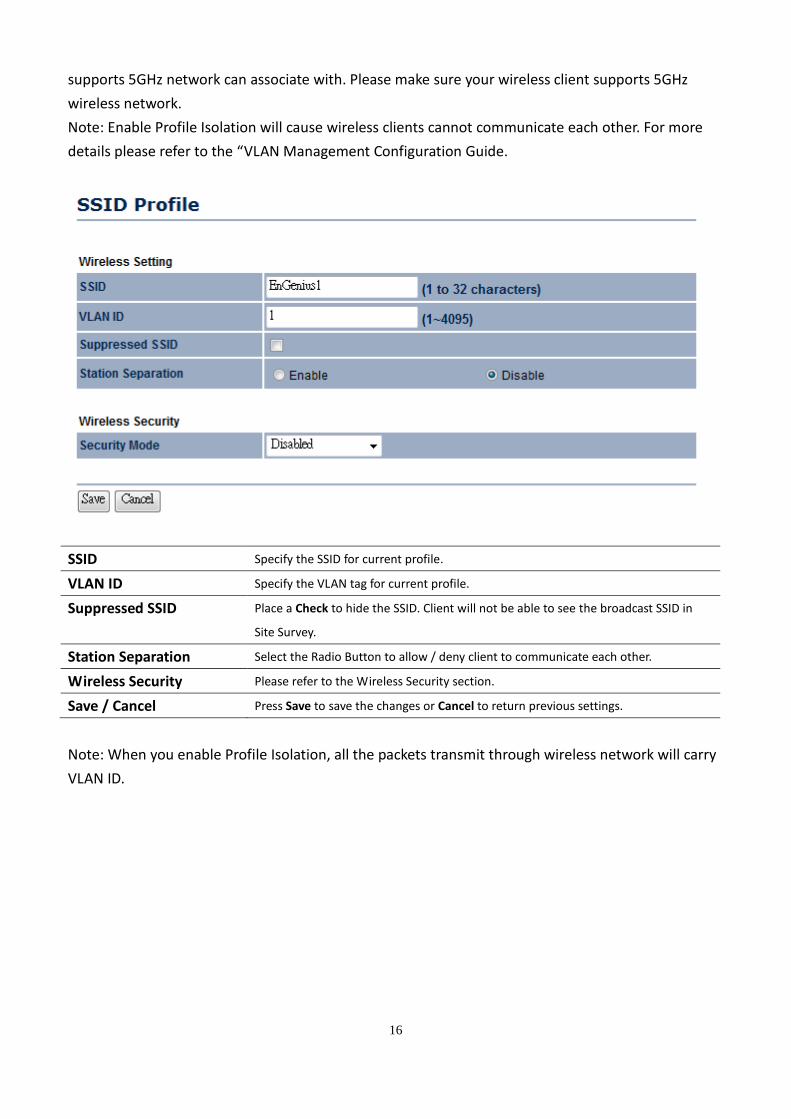
Auction: When you select 802.11a (5GHz) as your wireless mode, only the wireless client which
16
supports 5GHz network can associate with. Please make sure your wireless client supports 5GHz
wireless network.
Note: Enable Profile Isolation will cause wireless clients cannot communicate each other. For more
details please refer to the “VLAN Management Configuration Guide.
SSID Specify the SSID for current profile.
VLAN ID Specify the VLAN tag for current profile.
Suppressed SSID Place a Check to hide the SSID. Client will not be able to see the broadcast SSID in
Site Survey.
Station Separation Select the Radio Button to allow / deny client to communicate each other.
Wireless Security Please refer to the Wireless Security section.
Save / Cancel Press Save to save the changes or Cancel to return previous settings.
Note: When you enable Profile Isolation, all the packets transmit through wireless network will carry
VLAN ID.
17
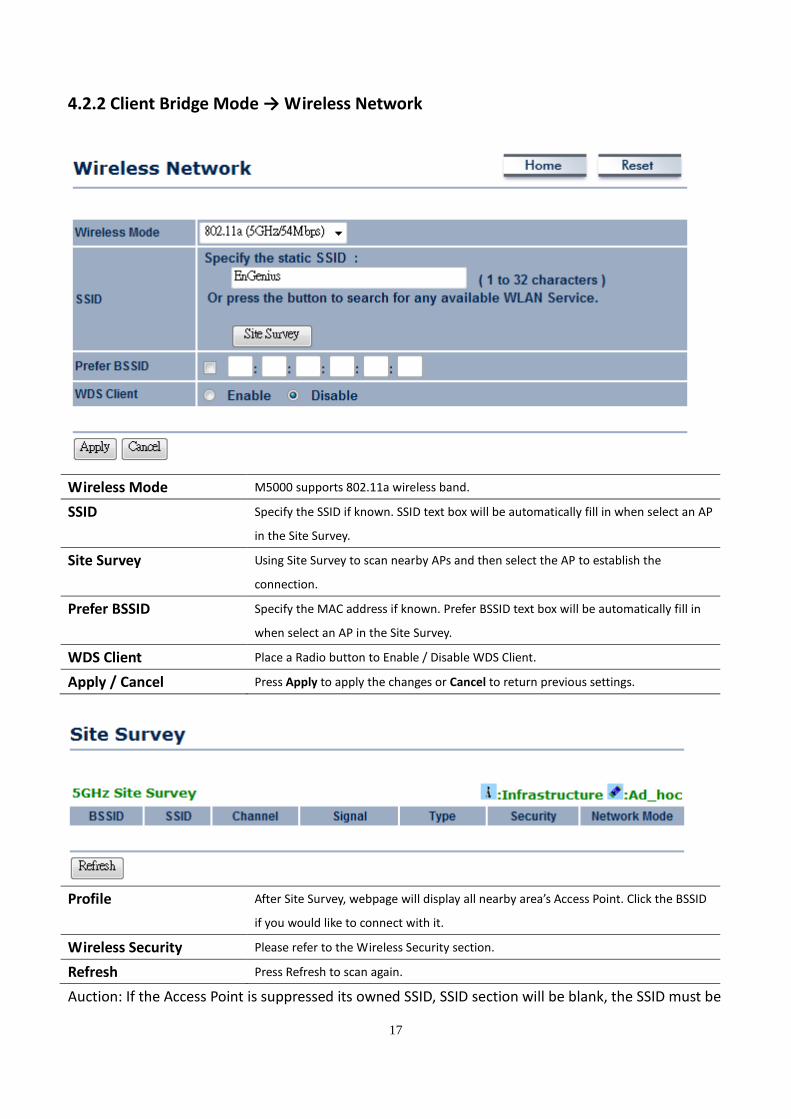
4.2.2 Client Bridge Mode → Wireless Network
Wireless Mode M5000 supports 802.11a wireless band.
SSID Specify the SSID if known. SSID text box will be automatically fill in when select an AP
in the Site Survey.
Site Survey Using Site Survey to scan nearby APs and then select the AP to establish the
connection.
Prefer BSSID Specify the MAC address if known. Prefer BSSID text box will be automatically fill in
when select an AP in the Site Survey.
WDS Client Place a Radio button to Enable / Disable WDS Client.
Apply / Cancel Press Apply to apply the changes or Cancel to return previous settings.
Profile After Site Survey, webpage will display all nearby area’s Access Point. Click the BSSID
if you would like to connect with it.
Wireless Security Please refer to the Wireless Security section.
Refresh Press Refresh to scan again.
Auction: If the Access Point is suppressed its owned SSID, SSID section will be blank, the SSID must be
18
filled in manually.
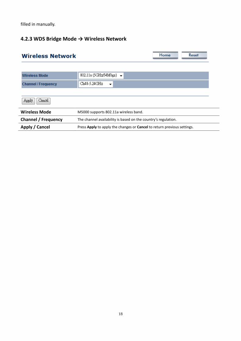
4.2.3 WDS Bridge Mode → Wireless Network
Wireless Mode M5000 supports 802.11a wireless band.
Channel / Frequency The channel availability is based on the country’s regulation.
Apply / Cancel Press Apply to apply the changes or Cancel to return previous settings.
19
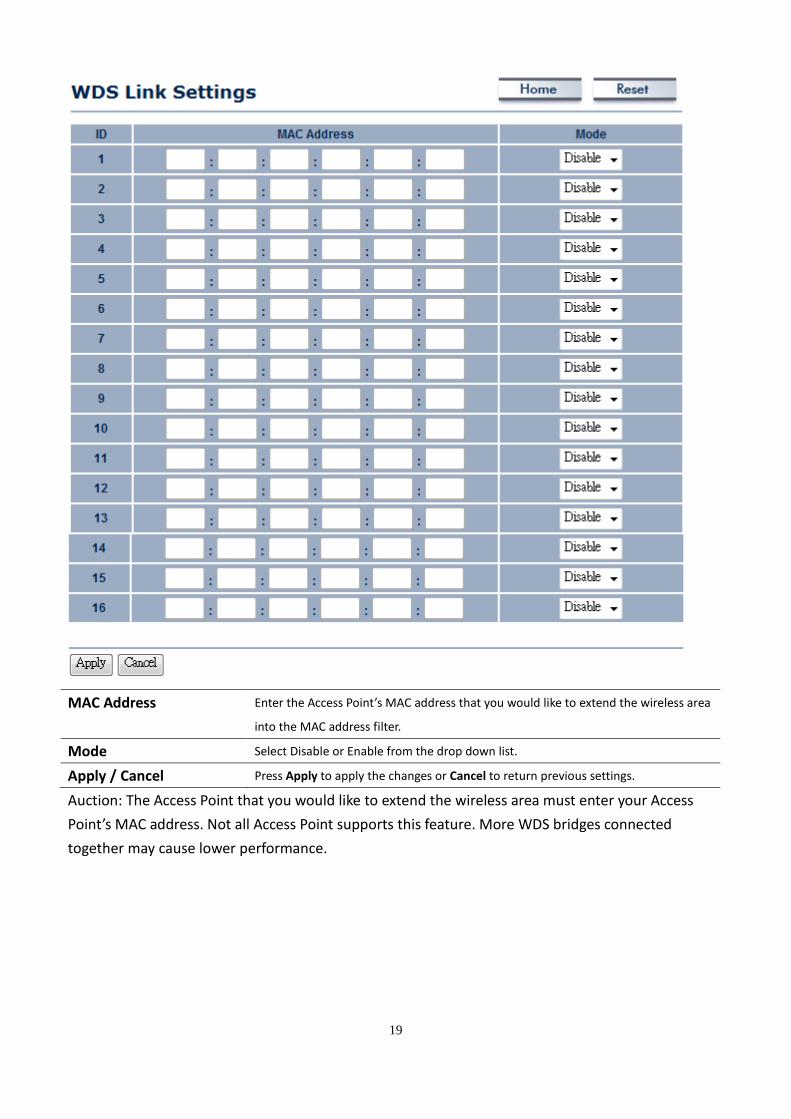
MAC Address Enter the Access Point’s MAC address that you would like to extend the wireless area
into the MAC address filter.
Mode Select Disable or Enable from the drop down list.
Apply / Cancel Press Apply to apply the changes or Cancel to return previous settings.
Auction: The Access Point that you would like to extend the wireless area must enter your Access
Point’s MAC address. Not all Access Point supports this feature. More WDS bridges connected
together may cause lower performance.
20
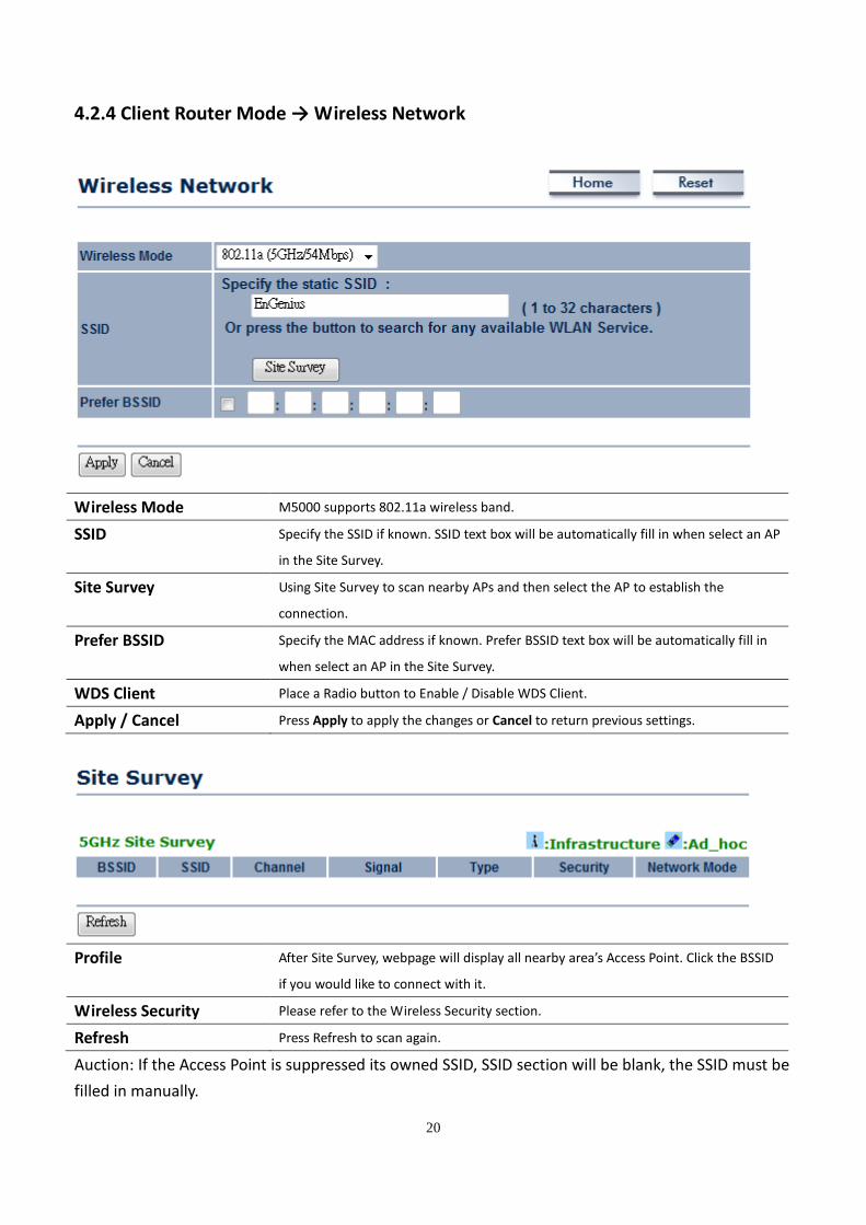
4.2.4 Client Router Mode → Wireless Network
Wireless Mode M5000 supports 802.11a wireless band.
SSID Specify the SSID if known. SSID text box will be automatically fill in when select an AP
in the Site Survey.
Site Survey Using Site Survey to scan nearby APs and then select the AP to establish the
connection.
Prefer BSSID Specify the MAC address if known. Prefer BSSID text box will be automatically fill in
when select an AP in the Site Survey.
WDS Client Place a Radio button to Enable / Disable WDS Client.
Apply / Cancel Press Apply to apply the changes or Cancel to return previous settings.
Profile After Site Survey, webpage will display all nearby area’s Access Point. Click the BSSID
if you would like to connect with it.
Wireless Security Please refer to the Wireless Security section.
Refresh Press Refresh to scan again.
Auction: If the Access Point is suppressed its owned SSID, SSID section will be blank, the SSID must be
filled in manually.
21
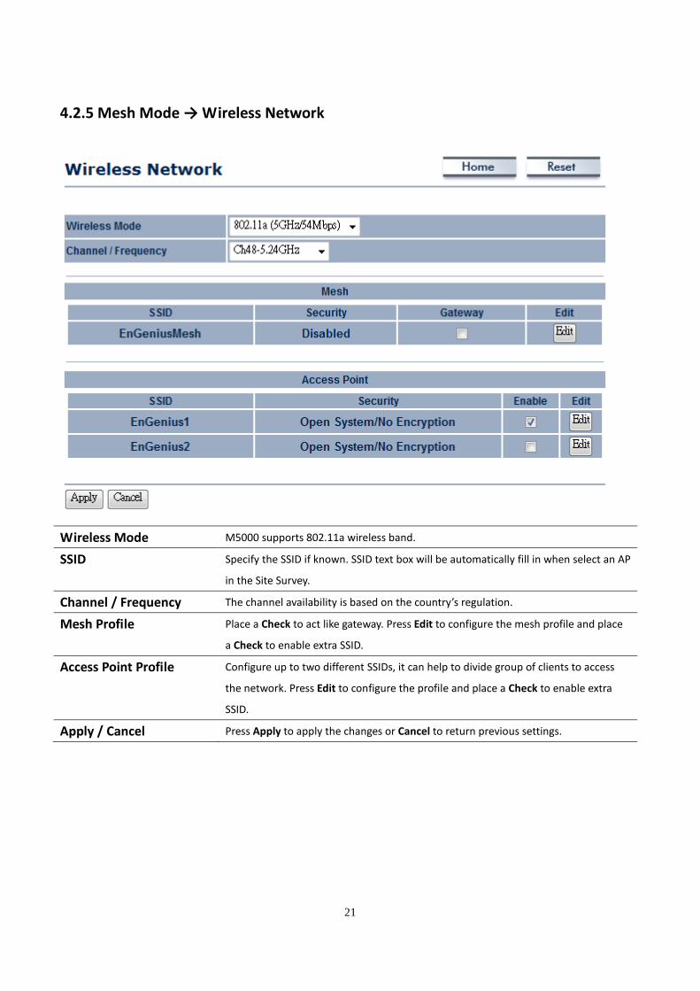
4.2.5 Mesh Mode → Wireless Network
Wireless Mode M5000 supports 802.11a wireless band.
SSID Specify the SSID if known. SSID text box will be automatically fill in when select an AP
in the Site Survey.
Channel / Frequency The channel availability is based on the country’s regulation.
Mesh Profile Place a Check to act like gateway. Press Edit to configure the mesh profile and place
a Check to enable extra SSID.
Access Point Profile Configure up to two different SSIDs, it can help to divide group of clients to access
the network. Press Edit to configure the profile and place a Check to enable extra
SSID.
Apply / Cancel Press Apply to apply the changes or Cancel to return previous settings.
22
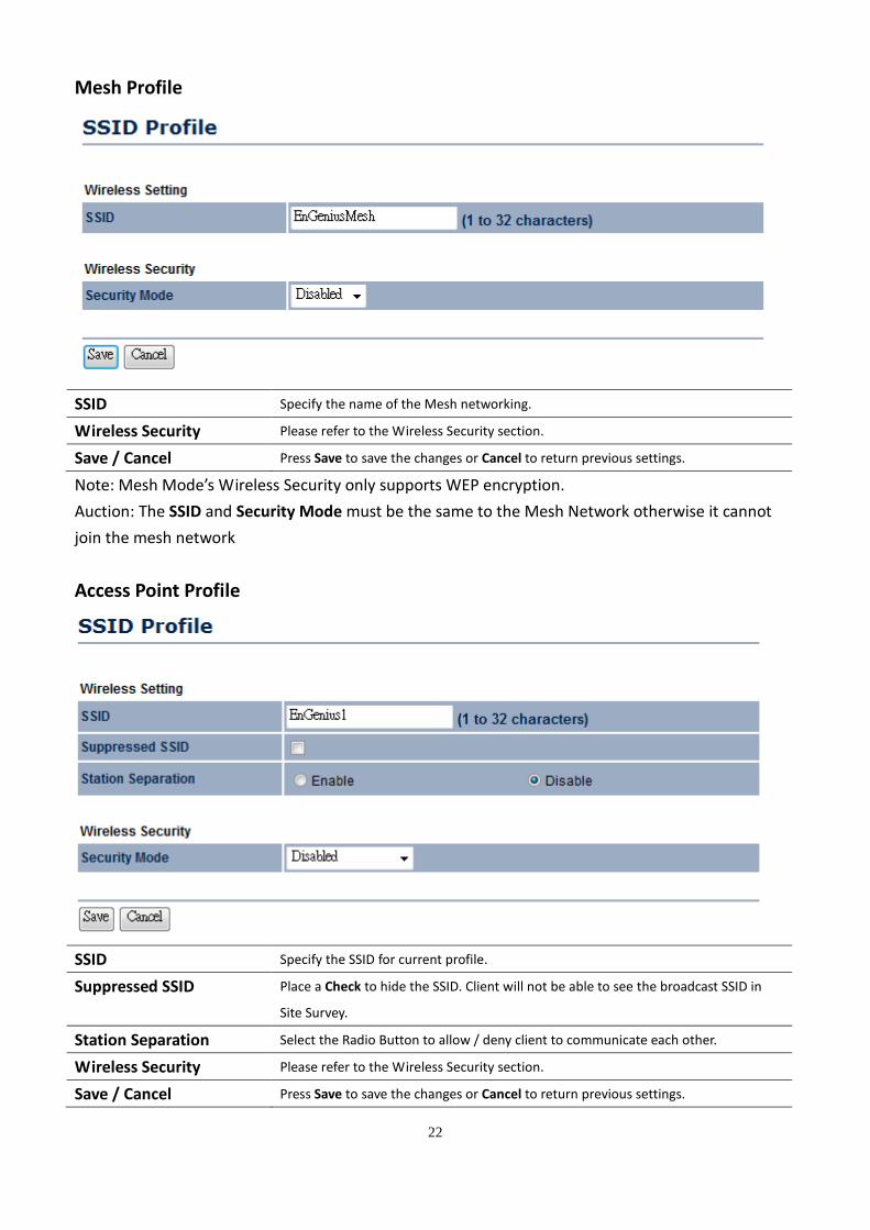
Mesh Profile
SSID Specify the name of the Mesh networking.
Wireless Security Please refer to the Wireless Security section.
Save / Cancel Press Save to save the changes or Cancel to return previous settings.
Note: Mesh Mode’s Wireless Security only supports WEP encryption.
Auction: The SSID and Security Mode must be the same to the Mesh Network otherwise it cannot
join the mesh network
Access Point Profile
SSID Specify the SSID for current profile.
Suppressed SSID Place a Check to hide the SSID. Client will not be able to see the broadcast SSID in
Site Survey.
Station Separation Select the Radio Button to allow / deny client to communicate each other.
Wireless Security Please refer to the Wireless Security section.
Save / Cancel Press Save to save the changes or Cancel to return previous settings.

23
Auction: M5000 only supports 802.11a (5GHz) wireless mode, only the wireless client which supports
5GHz network can associate with. Please make sure your wireless client supports 5GHz wireless
network.
24
4.3 Wireless Security Settings
Wireless Security Settings section will guide you to the entire Security modes configuration: WEP,
WPA-PSK, WPA2-PSK, WPA-PSK Mixed, WPA, WPA2, and WPA Mixed.
We strongly recommend that uses WPA2-PSK as your security settings.
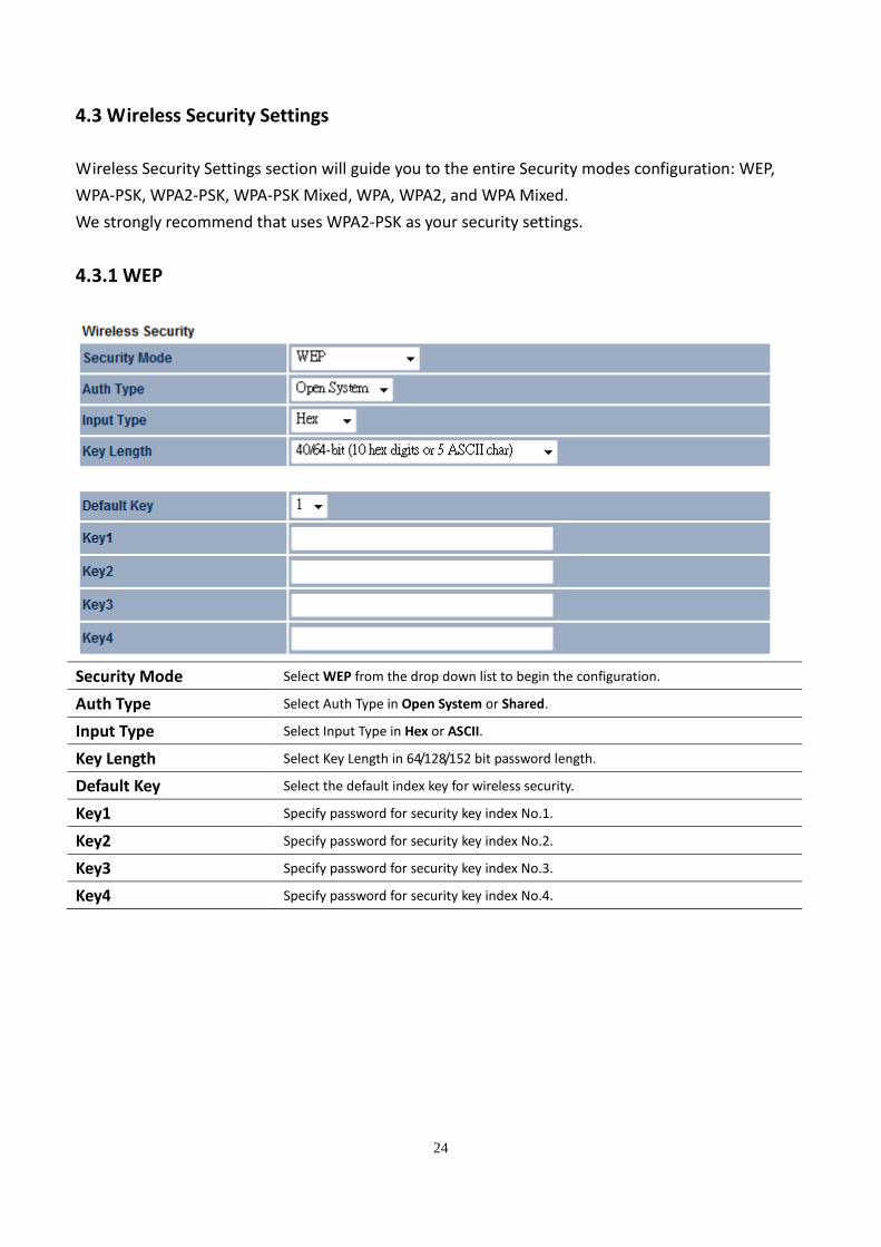
4.3.1 WEP
Security Mode Select WEP from the drop down list to begin the configuration.
Auth Type Select Auth Type in Open System or Shared.
Input Type Select Input Type in Hex or ASCII.
Key Length Select Key Length in 64/128/152 bit password length.
Default Key Select the default index key for wireless security.
Key1 Specify password for security key index No.1.
Key2 Specify password for security key index No.2.
Key3 Specify password for security key index No.3.
Key4 Specify password for security key index No.4.
25
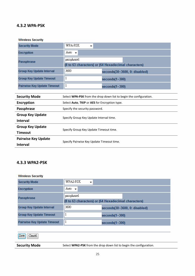
4.3.2 WPA-PSK
Security Mode Select WPA-PSK from the drop down list to begin the configuration.
Encryption Select Auto, TKIP or AES for Encryption type.
Passphrase Specify the security password.
Group Key Update
Interval Specify Group Key Update Interval time.
Group Key Update
Timeout Specify Group Key Update Timeout time.
Pairwise Key Update
Interval Specify Pairwise Key Update Timeout time.
4.3.3 WPA2-PSK
Security Mode Select WPA2-PSK from the drop down list to begin the configuration.
26
Encryption Select Auto, TKIP or AES for Encryption type.
Passphrase Specify the security password.
Group Key Update
Interval Specify Group Key Update Interval time.
Group Key Update
Timeout Specify Group Key Update Timeout time.
Pairwise Key Update
Interval Specify Pairwise Key Update Timeout time.
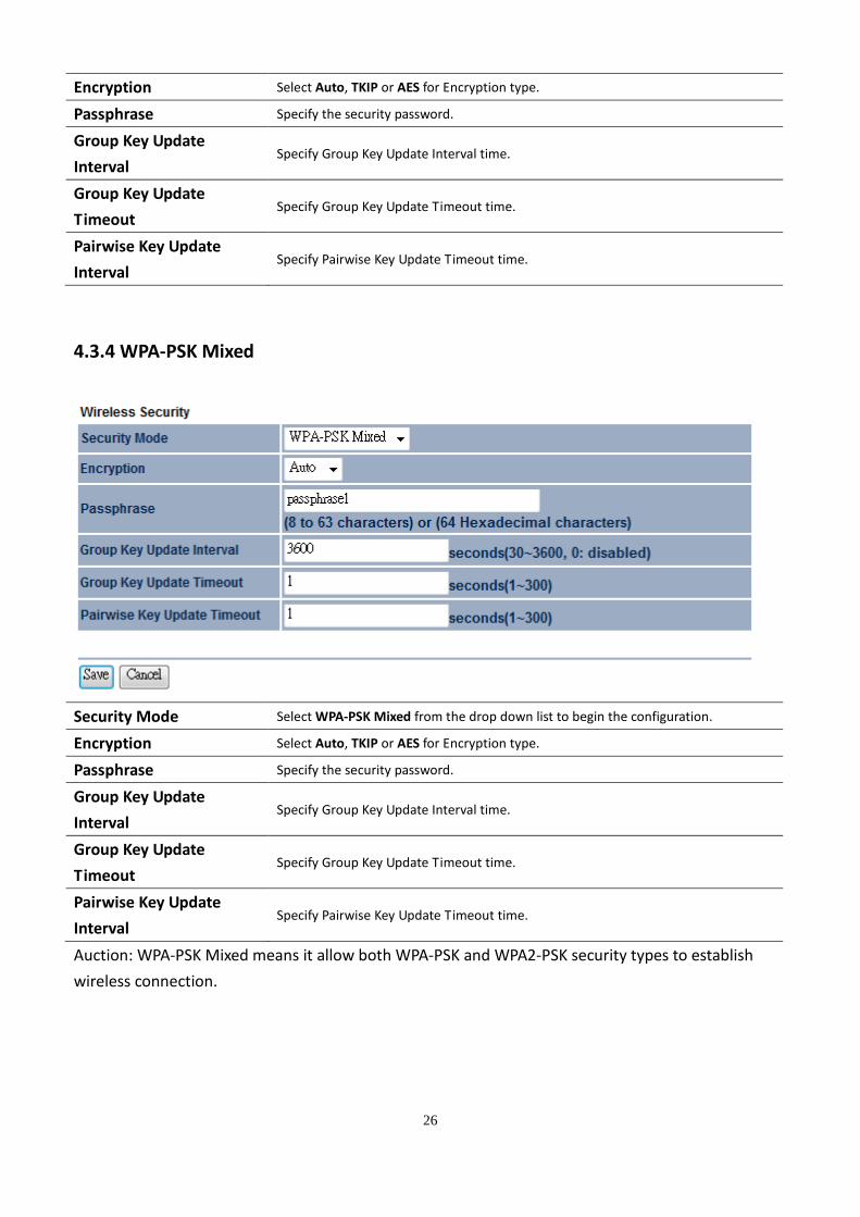
4.3.4 WPA-PSK Mixed
Security Mode Select WPA-PSK Mixed from the drop down list to begin the configuration.
Encryption Select Auto, TKIP or AES for Encryption type.
Passphrase Specify the security password.
Group Key Update
Interval Specify Group Key Update Interval time.
Group Key Update
Timeout Specify Group Key Update Timeout time.
Pairwise Key Update
Interval Specify Pairwise Key Update Timeout time.
Auction: WPA-PSK Mixed means it allow both WPA-PSK and WPA2-PSK security types to establish
wireless connection.

27
4.3.5 WPA
WPA security mode is for 802.1x authentication. You must provide a RADIUS Server to check the
permission of access the network.
Security Mode Select WPA from the drop down list to begin the configuration.
Encryption Select Auto, TKIP or AES for Encryption type.
Radius Server Specify Radius Server IP Address.
Radius Port Specify Radius Port number, the default port is 1812.
Radius Secret Specify Radius Secret that is given by the Radius Server.
Group Key Update
Interval Specify Group Key Update Interval time.
Group Key Update
Timeout Specify Group Key Update Timeout time.
Pairwise Key Update
Interval Specify Pairwise Key Update Timeout time.
Radius Accounting Select Enable or Disable Radius Accounting. The detail of Radius Accounting is at
next section.
28
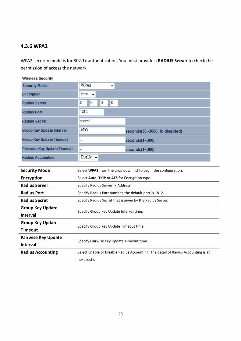
4.3.6 WPA2
WPA2 security mode is for 802.1x authentication. You must provide a RADIUS Server to check the
permission of access the network.
Security Mode Select WPA2 from the drop down list to begin the configuration.
Encryption Select Auto, TKIP or AES for Encryption type.
Radius Server Specify Radius Server IP Address.
Radius Port Specify Radius Port number, the default port is 1812.
Radius Secret Specify Radius Secret that is given by the Radius Server.
Group Key Update
Interval Specify Group Key Update Interval time.
Group Key Update
Timeout Specify Group Key Update Timeout time.
Pairwise Key Update
Interval Specify Pairwise Key Update Timeout time.
Radius Accounting Select Enable or Disable Radius Accounting. The detail of Radius Accounting is at
next section.
29
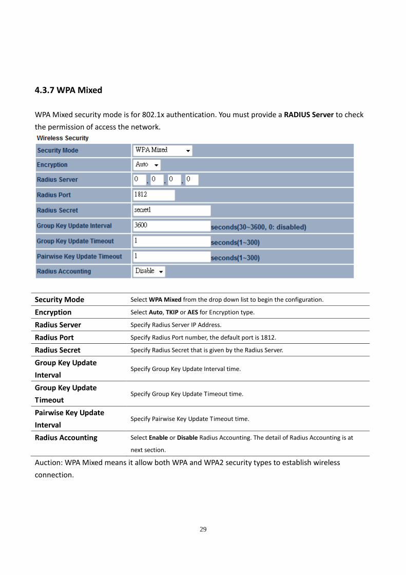
4.3.7 WPA Mixed
WPA Mixed security mode is for 802.1x authentication. You must provide a RADIUS Server to check
the permission of access the network.
Security Mode Select WPA Mixed from the drop down list to begin the configuration.
Encryption Select Auto, TKIP or AES for Encryption type.
Radius Server Specify Radius Server IP Address.
Radius Port Specify Radius Port number, the default port is 1812.
Radius Secret Specify Radius Secret that is given by the Radius Server.
Group Key Update
Interval Specify Group Key Update Interval time.
Group Key Update
Timeout Specify Group Key Update Timeout time.
Pairwise Key Update
Interval Specify Pairwise Key Update Timeout time.
Radius Accounting Select Enable or Disable Radius Accounting. The detail of Radius Accounting is at
next section.
Auction: WPA Mixed means it allow both WPA and WPA2 security types to establish wireless
connection.
30
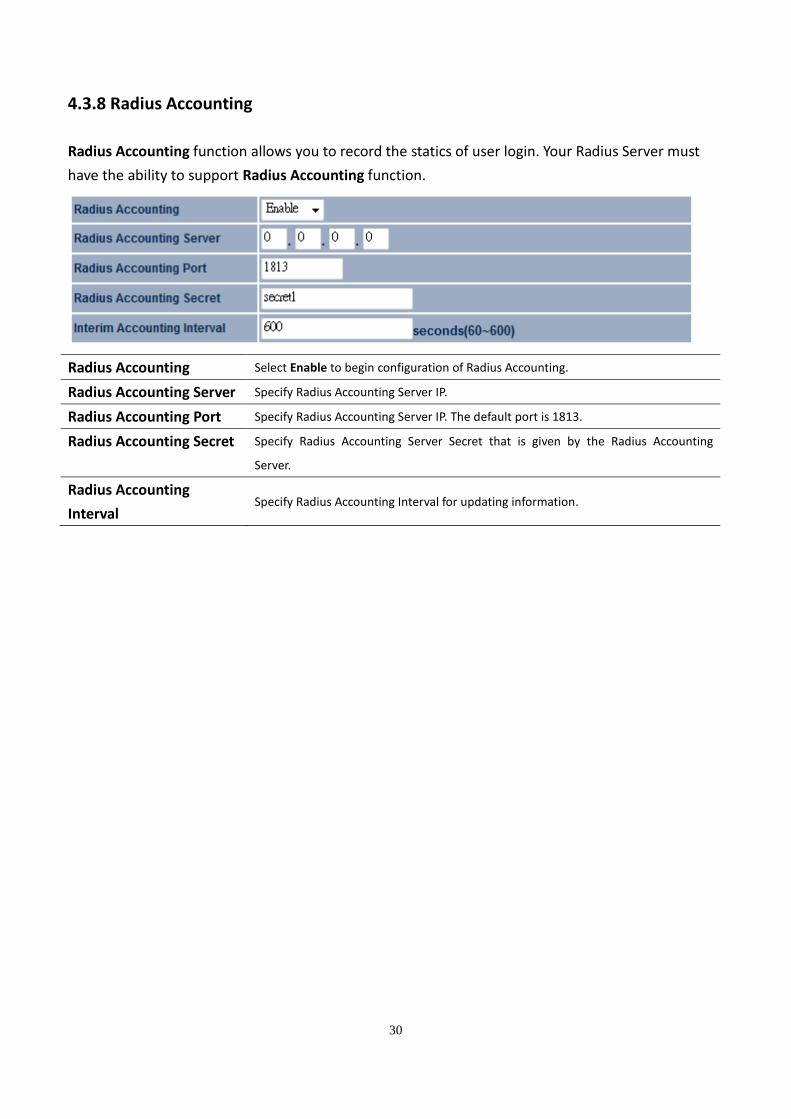
4.3.8 Radius Accounting
Radius Accounting function allows you to record the statics of user login. Your Radius Server must
have the ability to support Radius Accounting function.
Radius Accounting Select Enable to begin configuration of Radius Accounting.
Radius Accounting Server Specify Radius Accounting Server IP.
Radius Accounting Port Specify Radius Accounting Server IP. The default port is 1813.
Radius Accounting Secret Specify Radius Accounting Server Secret that is given by the Radius Accounting
Server.
Radius Accounting
Interval Specify Radius Accounting Interval for updating information.
31
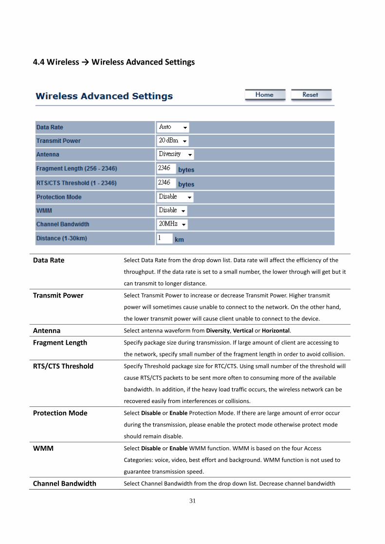
4.4 Wireless → Wireless Advanced Settings
Data Rate Select Data Rate from the drop down list. Data rate will affect the efficiency of the
throughput. If the data rate is set to a small number, the lower through will get but it
can transmit to longer distance.
Transmit Power Select Transmit Power to increase or decrease Transmit Power. Higher transmit
power will sometimes cause unable to connect to the network. On the other hand,
the lower transmit power will cause client unable to connect to the device.
Antenna Select antenna waveform from Diversity, Vertical or Horizontal.
Fragment Length Specify package size during transmission. If large amount of client are accessing to
the network, specify small number of the fragment length in order to avoid collision.
RTS/CTS Threshold Specify Threshold package size for RTC/CTS. Using small number of the threshold will
cause RTS/CTS packets to be sent more often to consuming more of the available
bandwidth. In addition, if the heavy load traffic occurs, the wireless network can be
recovered easily from interferences or collisions.
Protection Mode Select Disable or Enable Protection Mode. If there are large amount of error occur
during the transmission, please enable the protect mode otherwise protect mode
should remain disable.
WMM Select Disable or Enable WMM function. WMM is based on the four Access
Categories: voice, video, best effort and background. WMM function is not used to
guarantee transmission speed.
Channel Bandwidth Select Channel Bandwidth from the drop down list. Decrease channel bandwidth

32
may cause lower throughput but less collision.
Distance Specify distance rage between AP and Clients. Longer distance may lose high
connection speed.
Wireless Traffic Shaping Place a Check to enable Wireless Traffic Shaping function.
Incoming Traffic Limit Specify the wireless transmission speed for downloading.
Outgoing Traffic Limit Specify the wireless transmission speed for uploading.
Auction: Changing Wireless Advanced Settings may cause insufficient wireless connection quality.
Please remain all settings as default unless you have acknowledged all changing that you have made.
33
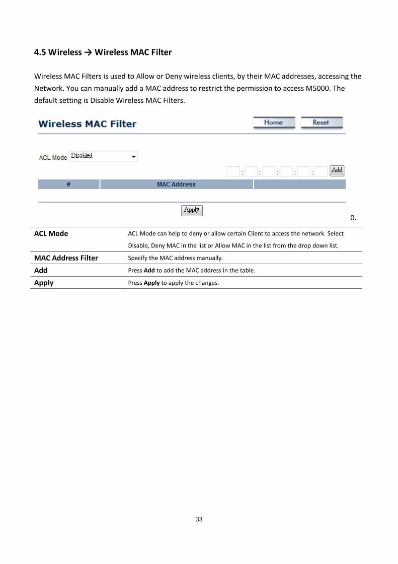
4.5 Wireless → Wireless MAC Filter
Wireless MAC Filters is used to Allow or Deny wireless clients, by their MAC addresses, accessing the
Network. You can manually add a MAC address to restrict the permission to access M5000. The
default setting is Disable Wireless MAC Filters.
0.
ACL Mode ACL Mode can help to deny or allow certain Client to access the network. Select
Disable, Deny MAC in the list or Allow MAC in the list from the drop down list.
MAC Address Filter Specify the MAC address manually.
Add Press Add to add the MAC address in the table.
Apply Press Apply to apply the changes.
34
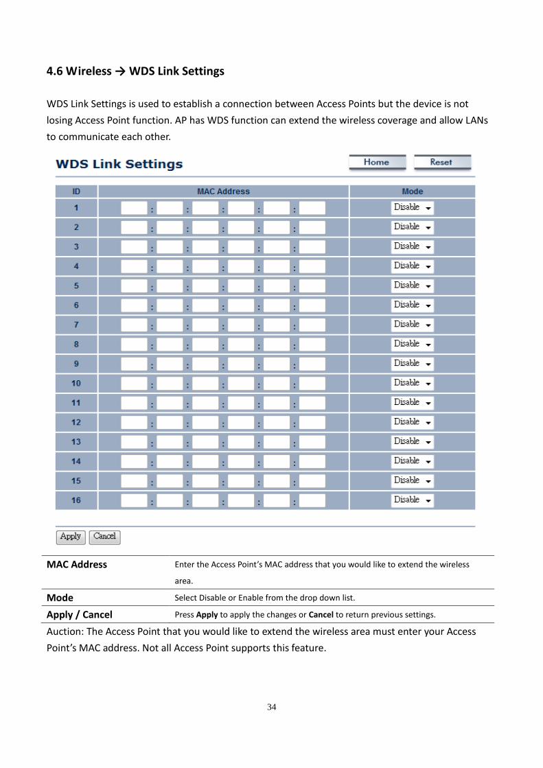
4.6 Wireless → WDS Link Settings
WDS Link Settings is used to establish a connection between Access Points but the device is not
losing Access Point function. AP has WDS function can extend the wireless coverage and allow LANs
to communicate each other.
MAC Address Enter the Access Point’s MAC address that you would like to extend the wireless
area.
Mode Select Disable or Enable from the drop down list.
Apply / Cancel Press Apply to apply the changes or Cancel to return previous settings.
Auction: The Access Point that you would like to extend the wireless area must enter your Access
Point’s MAC address. Not all Access Point supports this feature.
35
5 LAN Settings
This section will guide you to the Local Area Network (LAN) settings
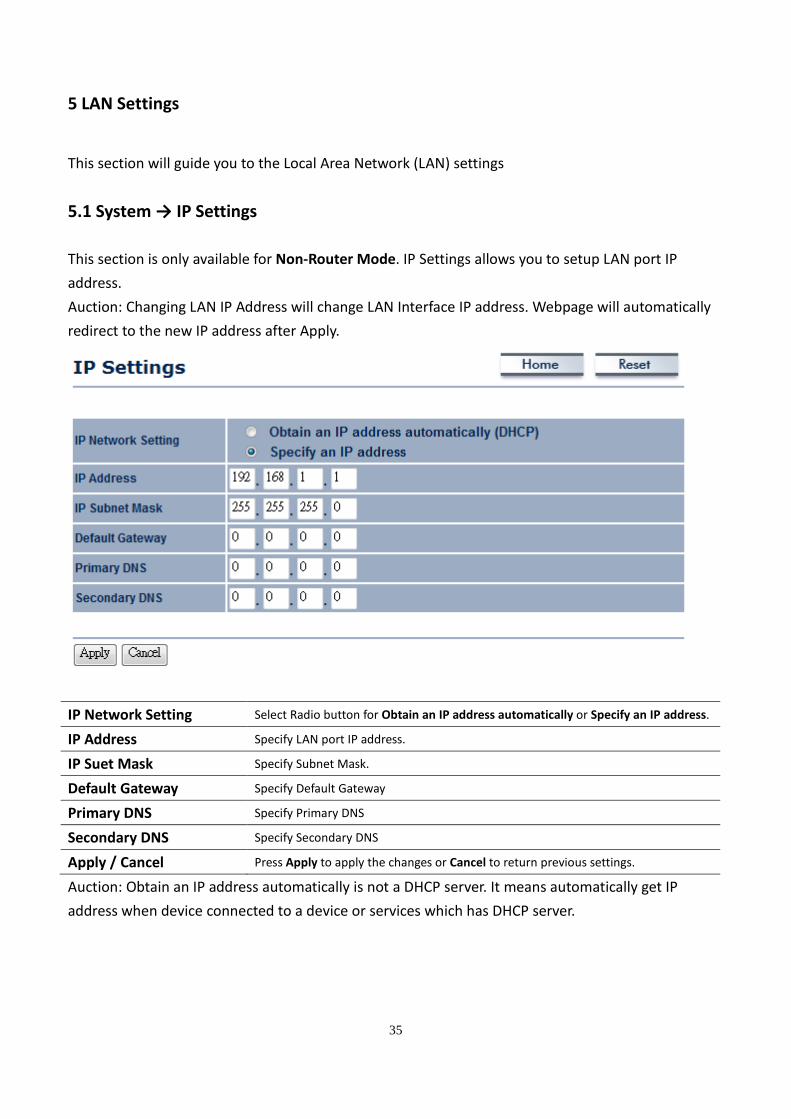
5.1 System → IP Settings
This section is only available for Non-Router Mode. IP Settings allows you to setup LAN port IP
address.
Auction: Changing LAN IP Address will change LAN Interface IP address. Webpage will automatically
redirect to the new IP address after Apply.
IP Network Setting Select Radio button for Obtain an IP address automatically or Specify an IP address.
IP Address Specify LAN port IP address.
IP Suet Mask Specify Subnet Mask.
Default Gateway Specify Default Gateway
Primary DNS Specify Primary DNS
Secondary DNS Specify Secondary DNS
Apply / Cancel Press Apply to apply the changes or Cancel to return previous settings.
Auction: Obtain an IP address automatically is not a DHCP server. It means automatically get IP
address when device connected to a device or services which has DHCP server.
36
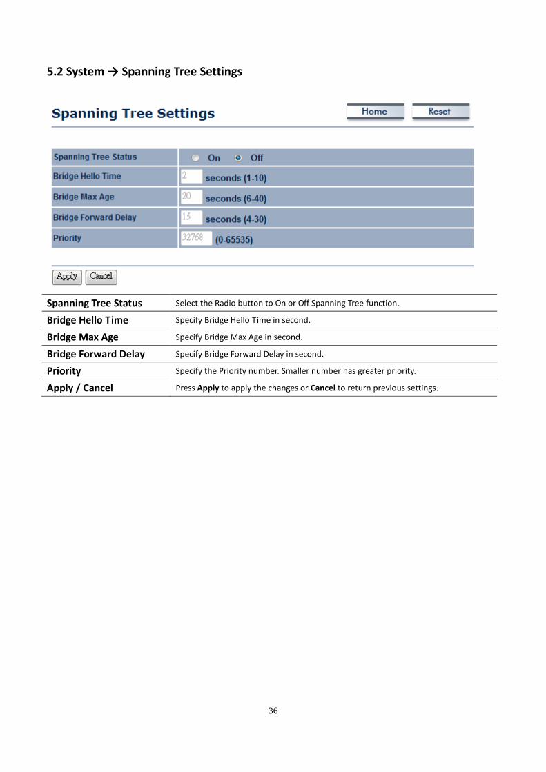
5.2 System → Spanning Tree Settings
Spanning Tree Status Select the Radio button to On or Off Spanning Tree function.
Bridge Hello Time Specify Bridge Hello Time in second.
Bridge Max Age Specify Bridge Max Age in second.
Bridge Forward Delay Specify Bridge Forward Delay in second.
Priority Specify the Priority number. Smaller number has greater priority.
Apply / Cancel Press Apply to apply the changes or Cancel to return previous settings.
37
6 Router Settings
This section is only available for AP Router Mode and Client Router Mode.
6.1 Router → WAN Settings
There are four different types of WAN connection: Static IP, DHCP, PPPoE and PPTP. Please contact
your ISP to select the connection type.
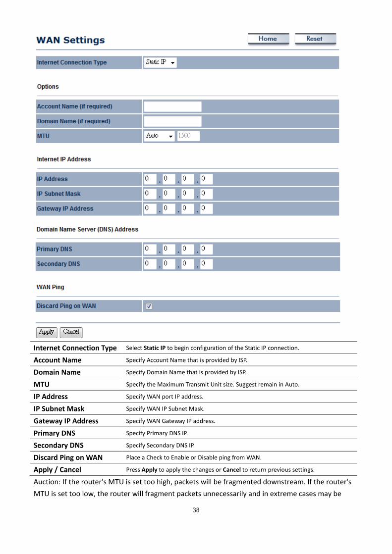
6.1.1 WAN Settings → Static IP
Select Static IP in WAN connection if your ISP gives all the information about IP address, Subnet Mask,
Default Gateway, Primary DNS and Secondary DNS.
38
Internet Connection Type Select Static IP to begin configuration of the Static IP connection.
Account Name Specify Account Name that is provided by ISP.
Domain Name Specify Domain Name that is provided by ISP.
MTU Specify the Maximum Transmit Unit size. Suggest remain in Auto.
IP Address Specify WAN port IP address.
IP Subnet Mask Specify WAN IP Subnet Mask.
Gateway IP Address Specify WAN Gateway IP address.
Primary DNS Specify Primary DNS IP.
Secondary DNS Specify Secondary DNS IP.
Discard Ping on WAN Place a Check to Enable or Disable ping from WAN.
Apply / Cancel Press Apply to apply the changes or Cancel to return previous settings.
Auction: If the router's MTU is set too high, packets will be fragmented downstream. If the router's
MTU is set too low, the router will fragment packets unnecessarily and in extreme cases may be

39
unable to establish some connections. In either case, network performance can suffer.
40
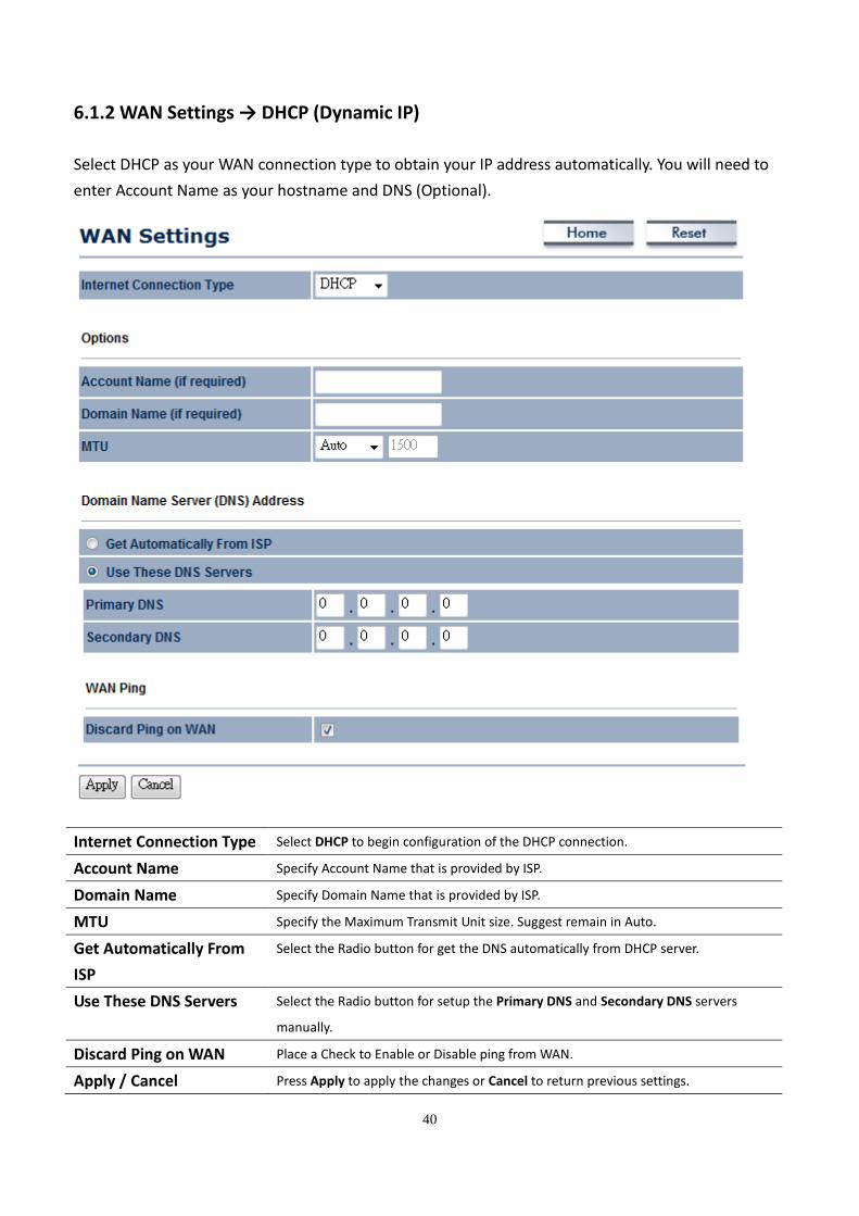
6.1.2 WAN Settings → DHCP (Dynamic IP)
Select DHCP as your WAN connection type to obtain your IP address automatically. You will need to
enter Account Name as your hostname and DNS (Optional).
Internet Connection Type Select DHCP to begin configuration of the DHCP connection.
Account Name Specify Account Name that is provided by ISP.
Domain Name Specify Domain Name that is provided by ISP.
MTU Specify the Maximum Transmit Unit size. Suggest remain in Auto.
Get Automatically From
ISP
Select the Radio button for get the DNS automatically from DHCP server.
Use These DNS Servers Select the Radio button for setup the Primary DNS and Secondary DNS servers
manually.
Discard Ping on WAN Place a Check to Enable or Disable ping from WAN.
Apply / Cancel Press Apply to apply the changes or Cancel to return previous settings.

41
Auction: If the router's MTU is set too high, packets will be fragmented downstream. If the router's
MTU is set too low, the router will fragment packets unnecessarily and in extreme cases may be
unable to establish some connections. In either case, network performance can suffer.
42
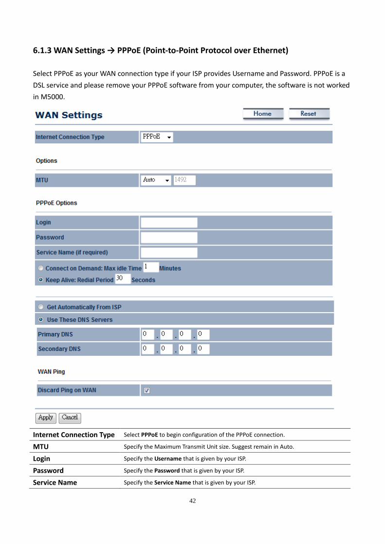
6.1.3 WAN Settings → PPPoE (Point-to-Point Protocol over Ethernet)
Select PPPoE as your WAN connection type if your ISP provides Username and Password. PPPoE is a
DSL service and please remove your PPPoE software from your computer, the software is not worked
in M5000.
Internet Connection Type Select PPPoE to begin configuration of the PPPoE connection.
MTU Specify the Maximum Transmit Unit size. Suggest remain in Auto.
Login Specify the Username that is given by your ISP.
Password Specify the Password that is given by your ISP.
Service Name Specify the Service Name that is given by your ISP.
43
Connect on Demand Select the Radio button to specify the maximum idle time. Internet connection will
disconnect when it reach the maximum idle time, but it will automatically connect
when user tries to access the network.
Keep Alive Select the Radio button to keep internet connection always on. Specify the redial
period once the internet lose connection.
Get Automatically From
ISP
Select the Radio button for get the DNS automatically from DHCP server.
Use These DNS Servers Select the Radio button for setup the Primary DNS and Secondary DNS servers
manually.
Discard Ping on WAN Place a Check to Enable or Disable ping from WAN.
Apply / Cancel Press Apply to apply the changes or Cancel to return previous settings.
Auction: If the router's MTU is set too high, packets will be fragmented downstream. If the router's
MTU is set too low, the router will fragment packets unnecessarily and in extreme cases may be
unable to establish some connections. In either case, network performance can suffer.
44
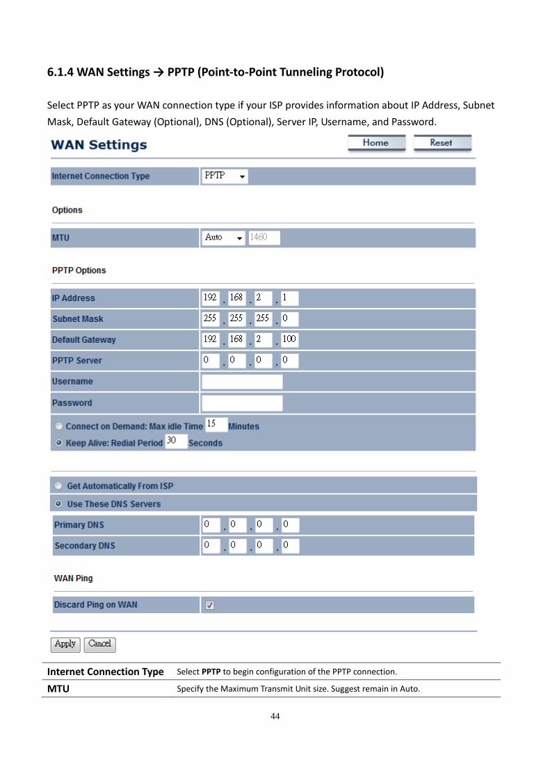
6.1.4 WAN Settings → PPTP (Point-to-Point Tunneling Protocol)
Select PPTP as your WAN connection type if your ISP provides information about IP Address, Subnet
Mask, Default Gateway (Optional), DNS (Optional), Server IP, Username, and Password.
Internet Connection Type Select PPTP to begin configuration of the PPTP connection.
MTU Specify the Maximum Transmit Unit size. Suggest remain in Auto.
45
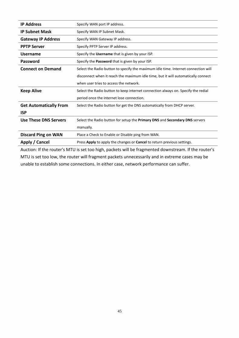
IP Address Specify WAN port IP address.
IP Subnet Mask Specify WAN IP Subnet Mask.
Gateway IP Address Specify WAN Gateway IP address.
PPTP Server Specify PPTP Server IP address.
Username Specify the Username that is given by your ISP.
Password Specify the Password that is given by your ISP.
Connect on Demand Select the Radio button to specify the maximum idle time. Internet connection will
disconnect when it reach the maximum idle time, but it will automatically connect
when user tries to access the network.
Keep Alive Select the Radio button to keep internet connection always on. Specify the redial
period once the internet lose connection.
Get Automatically From
ISP
Select the Radio button for get the DNS automatically from DHCP server.
Use These DNS Servers Select the Radio button for setup the Primary DNS and Secondary DNS servers
manually.
Discard Ping on WAN Place a Check to Enable or Disable ping from WAN.
Apply / Cancel Press Apply to apply the changes or Cancel to return previous settings.
Auction: If the router's MTU is set too high, packets will be fragmented downstream. If the router's
MTU is set too low, the router will fragment packets unnecessarily and in extreme cases may be
unable to establish some connections. In either case, network performance can suffer.
46
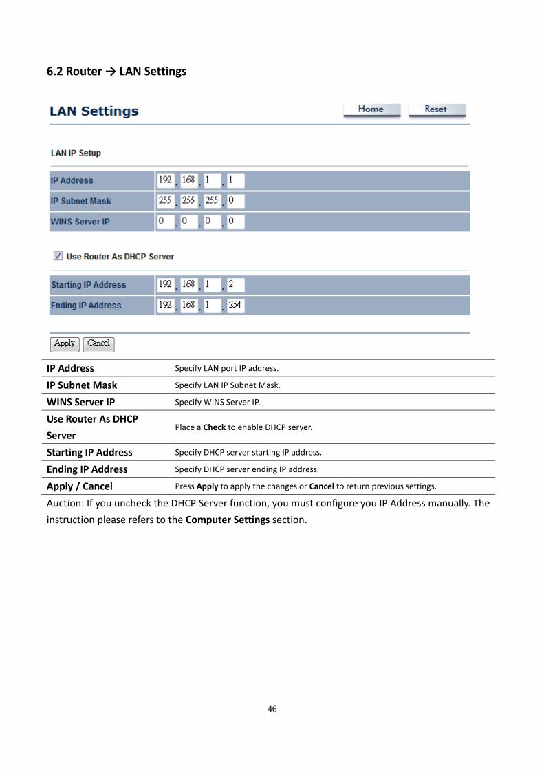
6.2 Router → LAN Settings
IP Address Specify LAN port IP address.
IP Subnet Mask Specify LAN IP Subnet Mask.
WINS Server IP Specify WINS Server IP.
Use Router As DHCP
Server Place a Check to enable DHCP server.
Starting IP Address Specify DHCP server starting IP address.
Ending IP Address Specify DHCP server ending IP address.
Apply / Cancel Press Apply to apply the changes or Cancel to return previous settings.
Auction: If you uncheck the DHCP Server function, you must configure you IP Address manually. The
instruction please refers to the Computer Settings section.
47
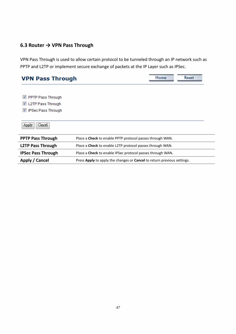
6.3 Router → VPN Pass Through
VPN Pass Through is used to allow certain protocol to be tunneled through an IP network such as
PPTP and L2TP or implement secure exchange of packets at the IP Layer such as IPSec.
PPTP Pass Through Place a Check to enable PPTP protocol passes through WAN.
L2TP Pass Through Place a Check to enable L2TP protocol passes through WAN.
IPSec Pass Through Place a Check to enable IPSec protocol passes through WAN.
Apply / Cancel Press Apply to apply the changes or Cancel to return previous settings.
48
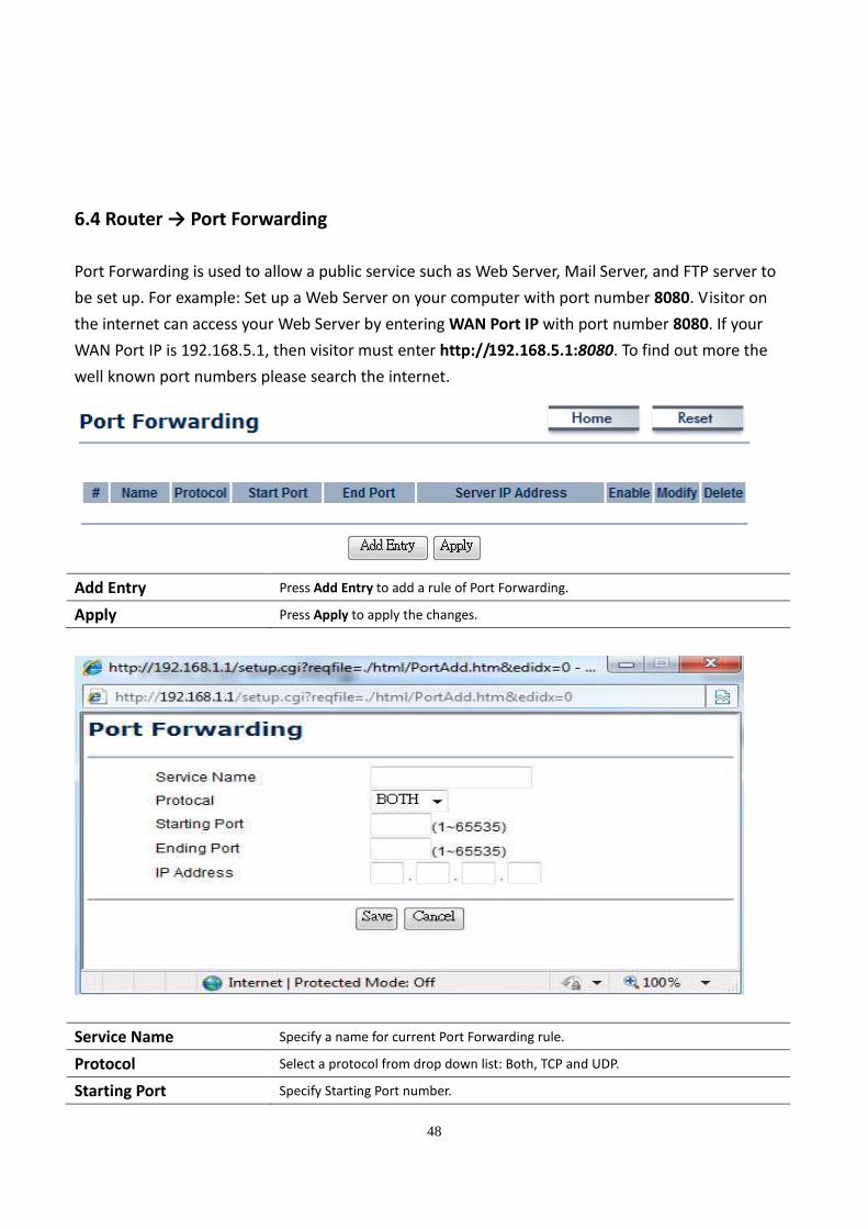
6.4 Router → Port Forwarding
Port Forwarding is used to allow a public service such as Web Server, Mail Server, and FTP server to
be set up. For example: Set up a Web Server on your computer with port number 8080. Visitor on
the internet can access your Web Server by entering WAN Port IP with port number 8080. If your
WAN Port IP is 192.168.5.1, then visitor must enter http://192.168.5.1:8080. To find out more the
well known port numbers please search the internet.
Add Entry Press Add Entry to add a rule of Port Forwarding.
Apply Press Apply to apply the changes.
Service Name Specify a name for current Port Forwarding rule.
Protocol Select a protocol from drop down list: Both, TCP and UDP.
Starting Port Specify Starting Port number.
49
Ending Port Specify Ending Port number.
IP Address Specify IP address.
Save / Cancel Press Save to apply the changes or Cancel to return previous settings.
7 Information Status
Status section is on the navigation drop-down menu. You will then see three options: Main, Wireless
Client List, System Log, WDS Link Status, Connection Status, and DHCP Client Table. Each option is
described in detail below.
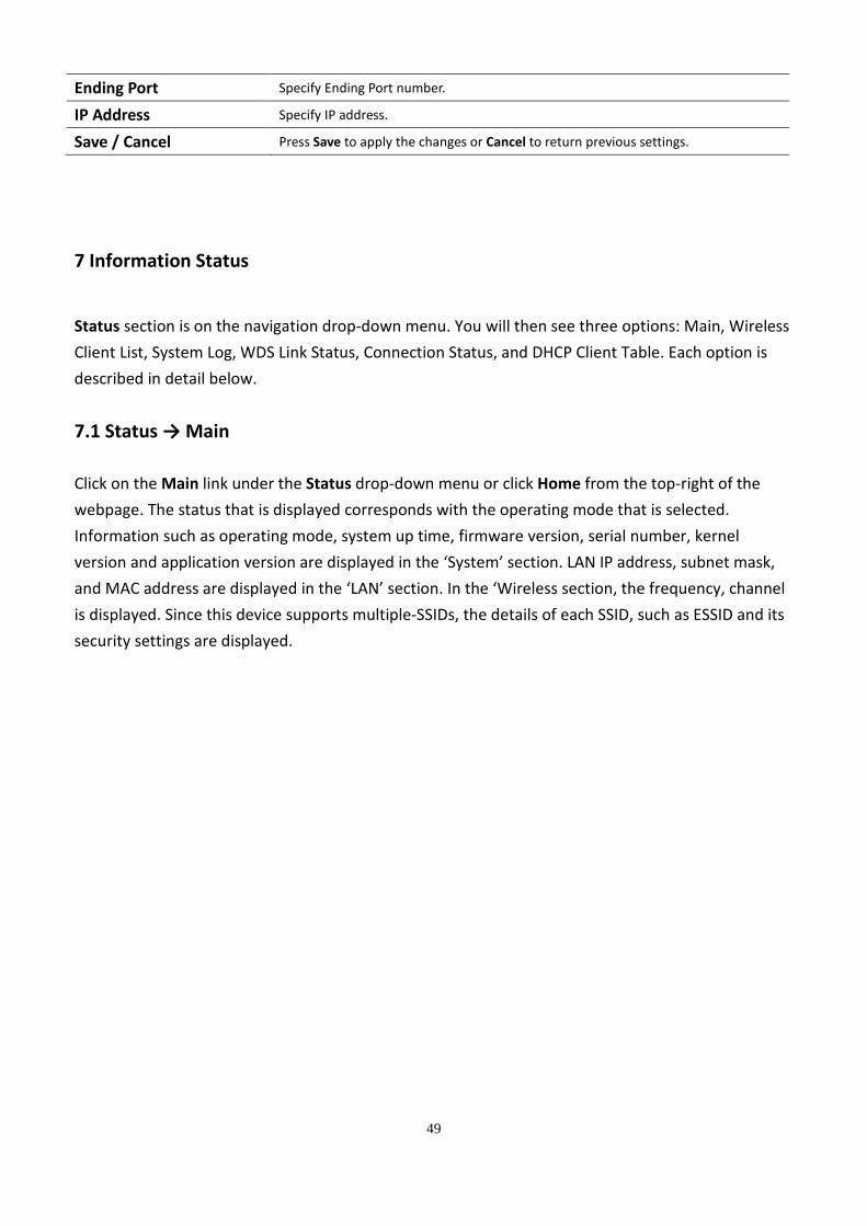
7.1 Status → Main
Click on the Main link under the Status drop-down menu or click Home from the top-right of the
webpage. The status that is displayed corresponds with the operating mode that is selected.
Information such as operating mode, system up time, firmware version, serial number, kernel
version and application version are displayed in the ‘System’ section. LAN IP address, subnet mask,
and MAC address are displayed in the ‘LAN’ section. In the ‘Wireless section, the frequency, channel
is displayed. Since this device supports multiple-SSIDs, the details of each SSID, such as ESSID and its
security settings are displayed.
50
51
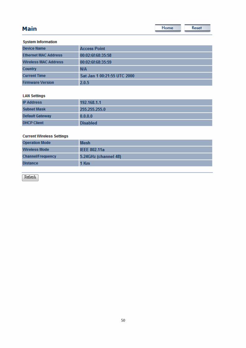
7.2 Status → Wireless Client List
Click on the Wireless Client List link under the Status drop-down menu. This page displays the list of
Clients that are associated to the M5000.
The MAC addresses and signal strength for each client is displayed. Click on the Refresh button to
refresh the client list
52
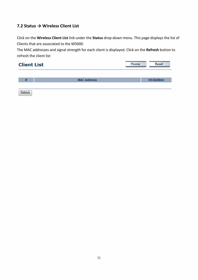
7.3 Status → System Log
Click on the System Log link under the Status drop-down menu. The device automatically logs
(records) events of possible interest in its internal memory. If there is not enough internal memory
for all events, logs of older events are deleted, but logs of the latest events are retained.
53
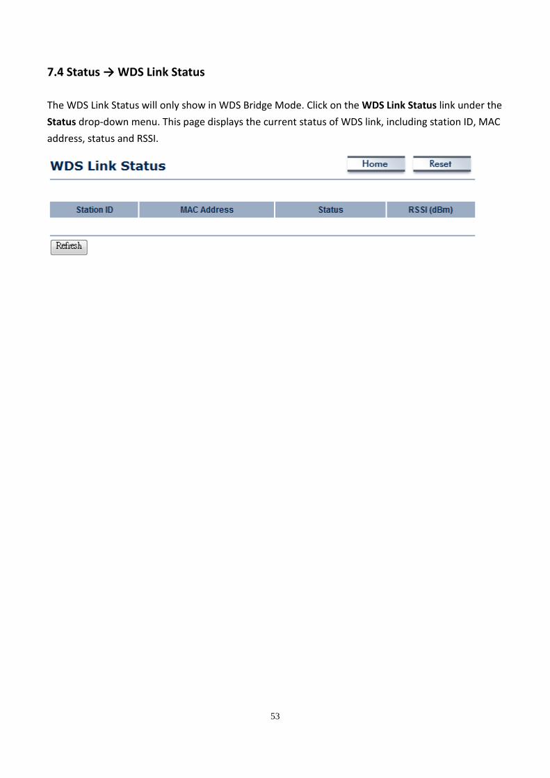
7.4 Status → WDS Link Status
The WDS Link Status will only show in WDS Bridge Mode. Click on the WDS Link Status link under the
Status drop-down menu. This page displays the current status of WDS link, including station ID, MAC
address, status and RSSI.
54
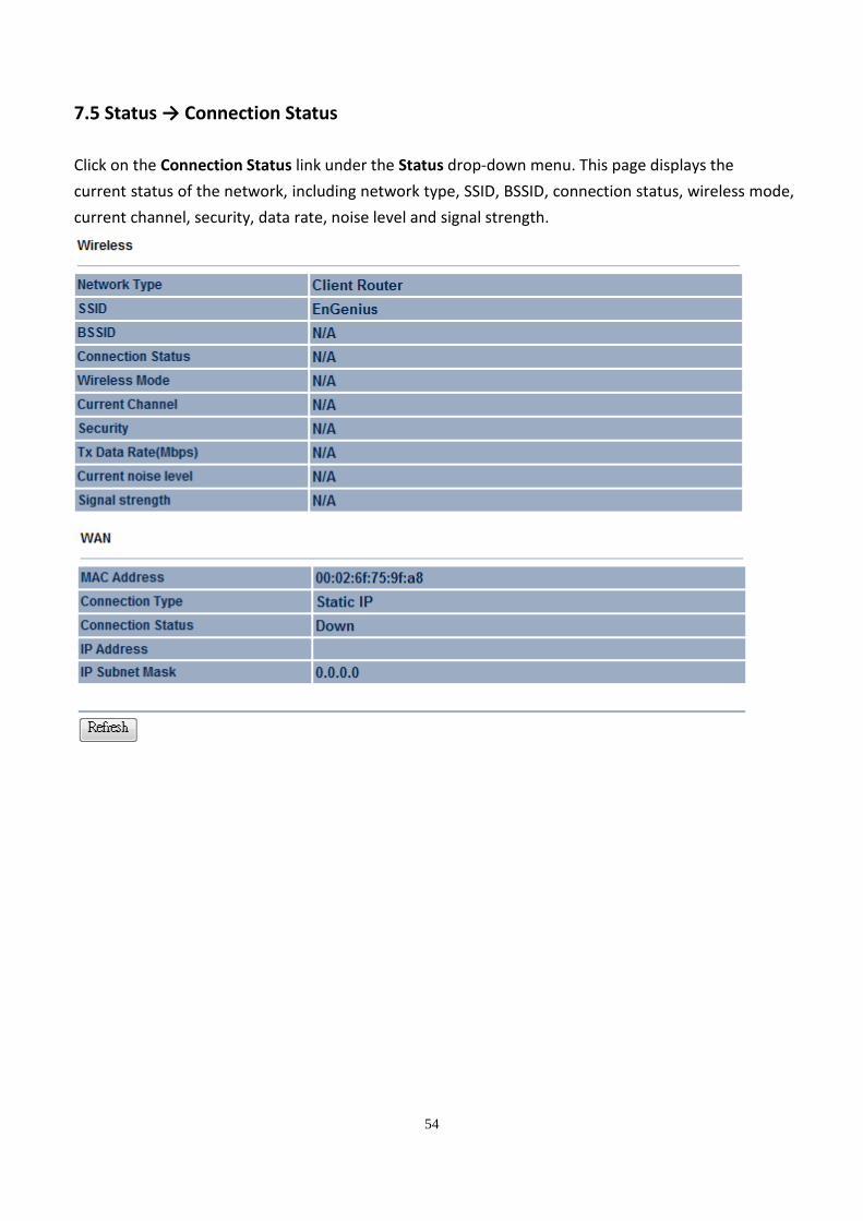
7.5 Status → Connection Status
Click on the Connection Status link under the Status drop-down menu. This page displays the
current status of the network, including network type, SSID, BSSID, connection status, wireless mode,
current channel, security, data rate, noise level and signal strength.
55
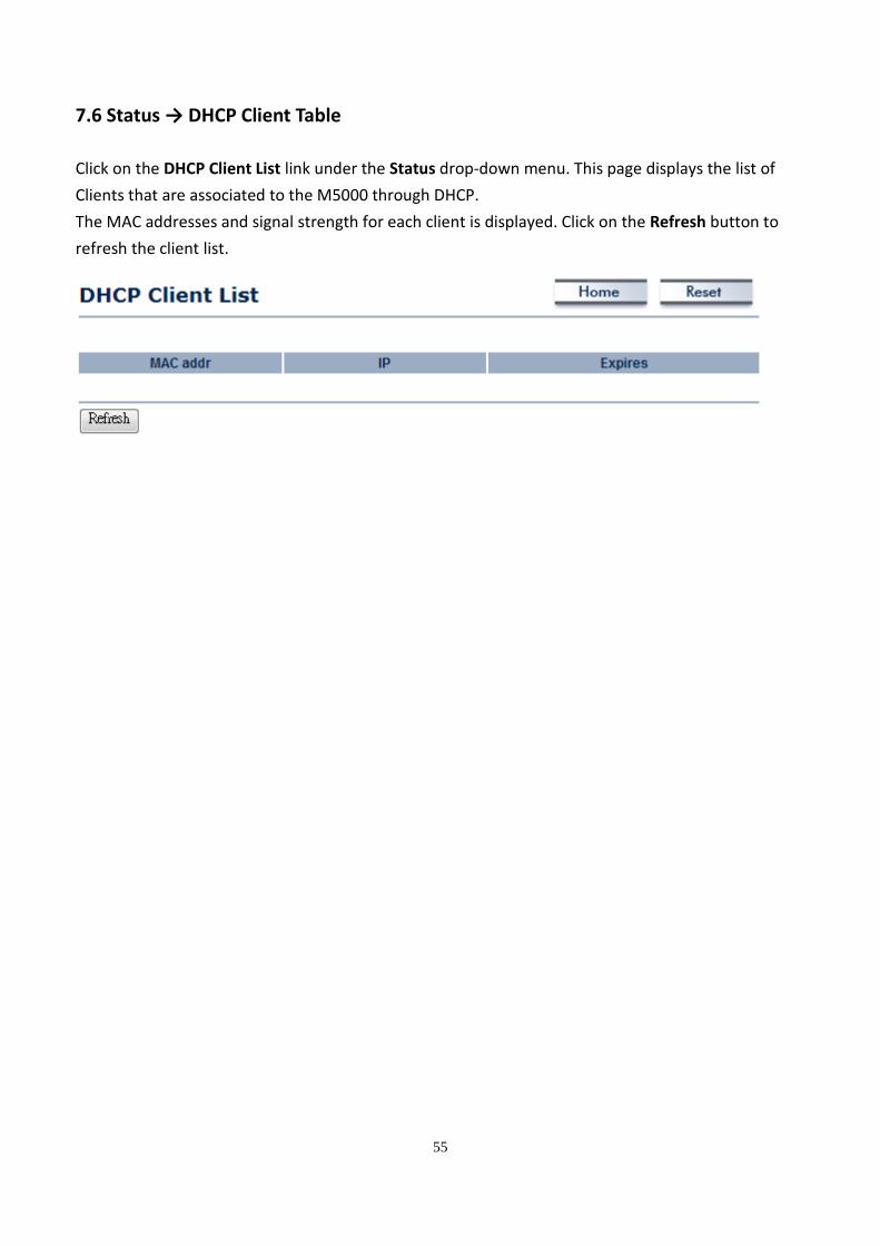
7.6 Status → DHCP Client Table
Click on the DHCP Client List link under the Status drop-down menu. This page displays the list of
Clients that are associated to the M5000 through DHCP.
The MAC addresses and signal strength for each client is displayed. Click on the Refresh button to
refresh the client list.
56
8 Management Settings
Management section is on the navigation drop-down menu. You will then see seven options:
administration, management VLAN, SNMP settings, backup/restore settings, firmware upgrade, time
settings, and log. Each option is described below.
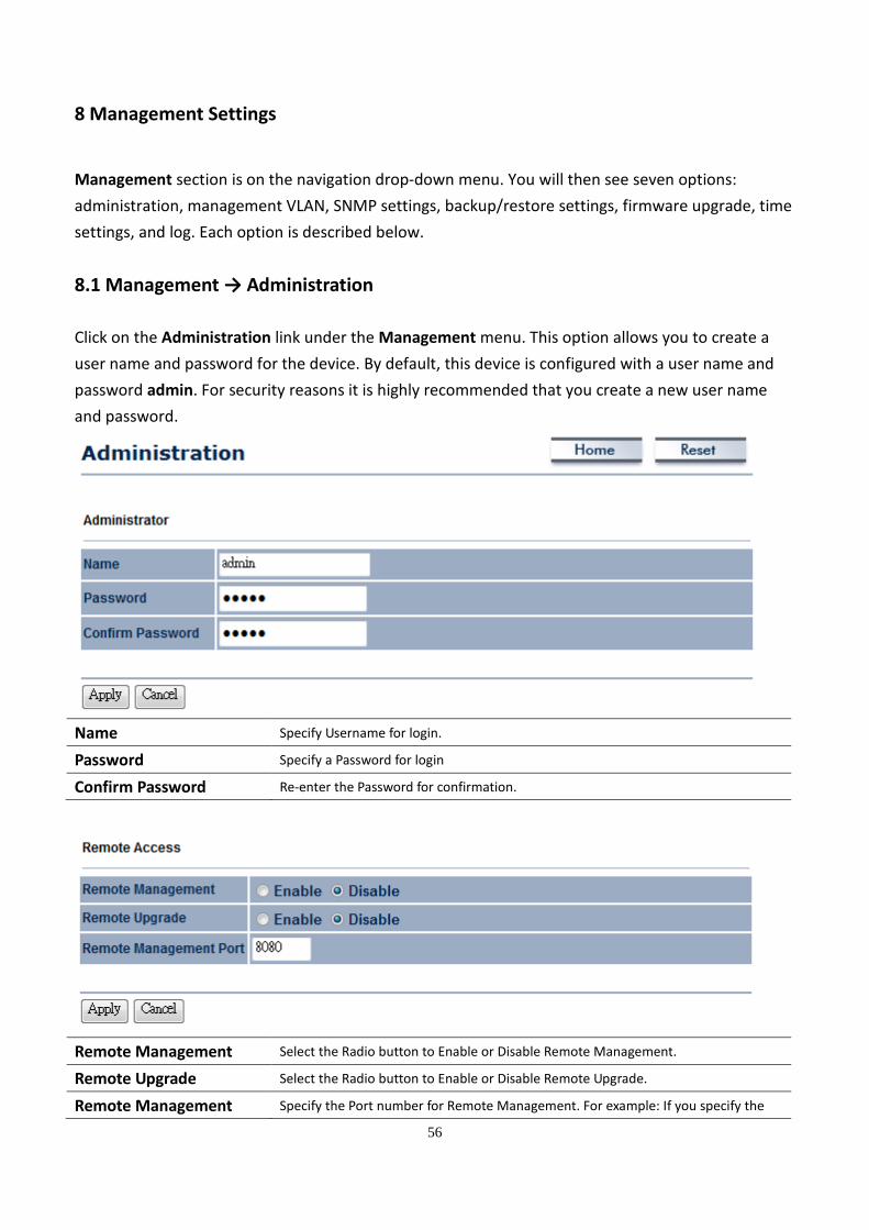
8.1 Management → Administration
Click on the Administration link under the Management menu. This option allows you to create a
user name and password for the device. By default, this device is configured with a user name and
password admin. For security reasons it is highly recommended that you create a new user name
and password.
Name Specify Username for login.
Password Specify a Password for login
Confirm Password Re-enter the Password for confirmation.
Remote Management Select the Radio button to Enable or Disable Remote Management.
Remote Upgrade Select the Radio button to Enable or Disable Remote Upgrade.
Remote Management Specify the Port number for Remote Management. For example: If you specify the

57
Port Port number is 8080, then you will need to enter following http://<IP address>:8080
to access the web interface.
Apply / Cancel Press Apply to apply the changes or Cancel to return previous settings.
58
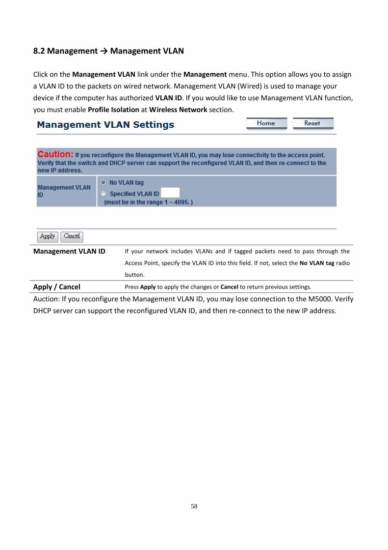
8.2 Management → Management VLAN
Click on the Management VLAN link under the Management menu. This option allows you to assign
a VLAN ID to the packets on wired network. Management VLAN (Wired) is used to manage your
device if the computer has authorized VLAN ID. If you would like to use Management VLAN function,
you must enable Profile Isolation at Wireless Network section.
Management VLAN ID If your network includes VLANs and if tagged packets need to pass through the
Access Point, specify the VLAN ID into this field. If not, select the No VLAN tag radio
button.
Apply / Cancel Press Apply to apply the changes or Cancel to return previous settings.
Auction: If you reconfigure the Management VLAN ID, you may lose connection to the M5000. Verify
DHCP server can support the reconfigured VLAN ID, and then re-connect to the new IP address.
59
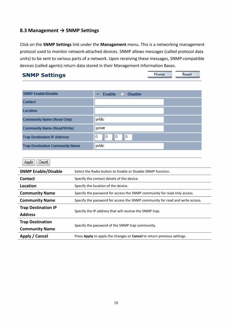
8.3 Management → SNMP Settings
Click on the SNMP Settings link under the Management menu. This is a networking management
protocol used to monitor network-attached devices. SNMP allows messages (called protocol data
units) to be sent to various parts of a network. Upon receiving these messages, SNMP-compatible
devices (called agents) return data stored in their Management Information Bases.
SNMP Enable/Disable Select the Radio button to Enable or Disable SNMP function.
Contact Specify the contact details of the device.
Location Specify the location of the device.
Community Name Specify the password for access the SNMP community for read only access.
Community Name Specify the password for access the SNMP community for read and write access.
Trap Destination IP
Address Specify the IP address that will receive the SNMP trap.
Trap Destination
Community Name Specify the password of the SNMP trap community.
Apply / Cancel Press Apply to apply the changes or Cancel to return previous settings.
60
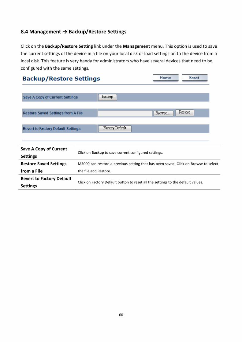
8.4 Management → Backup/Restore Settings
Click on the Backup/Restore Setting link under the Management menu. This option is used to save
the current settings of the device in a file on your local disk or load settings on to the device from a
local disk. This feature is very handy for administrators who have several devices that need to be
configured with the same settings.
Save A Copy of Current
Settings Click on Backup to save current configured settings.
Restore Saved Settings
from a File
M5000 can restore a previous setting that has been saved. Click on Browse to select
the file and Restore.
Revert to Factory Default
Settings Click on Factory Default button to reset all the settings to the default values.
61
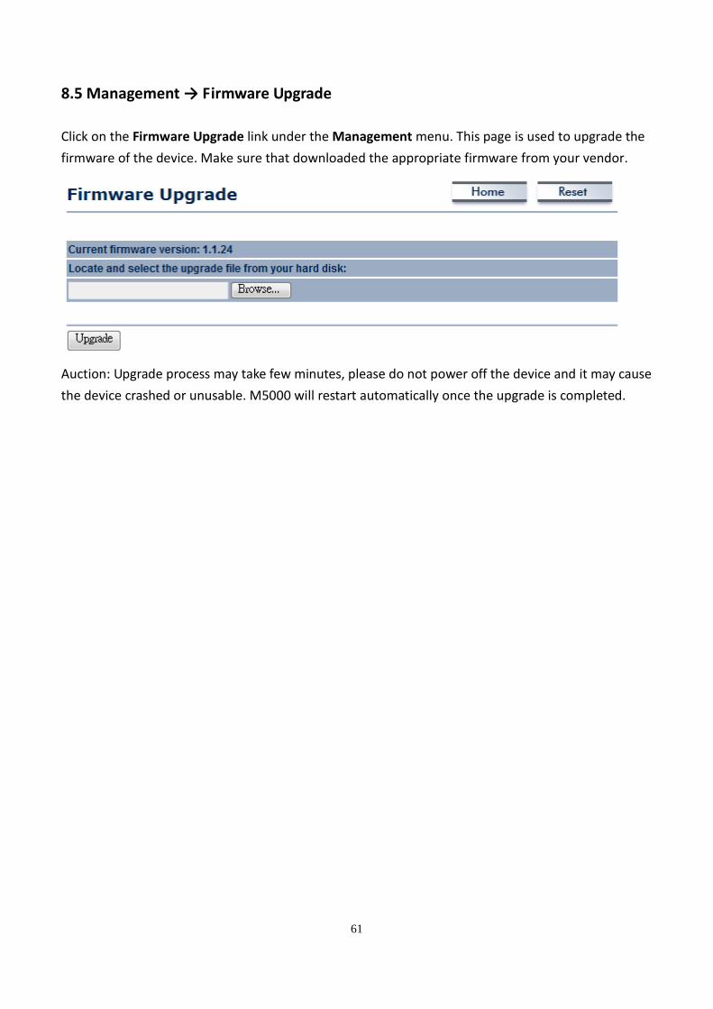
8.5 Management → Firmware Upgrade
Click on the Firmware Upgrade link under the Management menu. This page is used to upgrade the
firmware of the device. Make sure that downloaded the appropriate firmware from your vendor.
Auction: Upgrade process may take few minutes, please do not power off the device and it may cause
the device crashed or unusable. M5000 will restart automatically once the upgrade is completed.
62
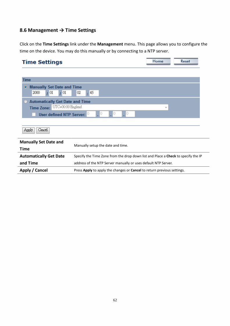
8.6 Management → Time Settings
Click on the Time Settings link under the Management menu. This page allows you to configure the
time on the device. You may do this manually or by connecting to a NTP server.
Manually Set Date and
Time Manually setup the date and time.
Automatically Get Date
and Time
Specify the Time Zone from the drop down list and Place a Check to specify the IP
address of the NTP Server manually or uses default NTP Server.
Apply / Cancel Press Apply to apply the changes or Cancel to return previous settings.
63
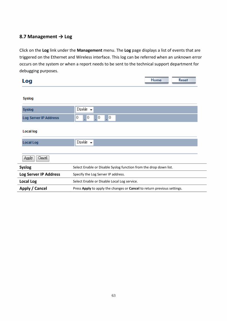
8.7 Management → Log
Click on the Log link under the Management menu. The Log page displays a list of events that are
triggered on the Ethernet and Wireless interface. This log can be referred when an unknown error
occurs on the system or when a report needs to be sent to the technical support department for
debugging purposes.
Syslog Select Enable or Disable Syslog function from the drop down list.
Log Server IP Address Specify the Log Server IP address.
Local Log Select Enable or Disable Local Log service.
Apply / Cancel Press Apply to apply the changes or Cancel to return previous settings.
64
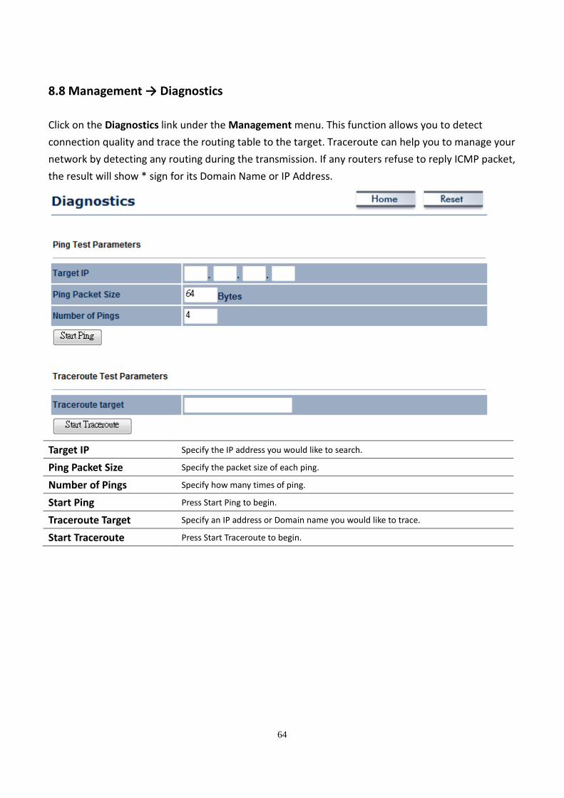
8.8 Management → Diagnostics
Click on the Diagnostics link under the Management menu. This function allows you to detect
connection quality and trace the routing table to the target. Traceroute can help you to manage your
network by detecting any routing during the transmission. If any routers refuse to reply ICMP packet,
the result will show * sign for its Domain Name or IP Address.
Target IP Specify the IP address you would like to search.
Ping Packet Size Specify the packet size of each ping.
Number of Pings Specify how many times of ping.
Start Ping Press Start Ping to begin.
Traceroute Target Specify an IP address or Domain name you would like to trace.
Start Traceroute Press Start Traceroute to begin.
65
9 Network Configuration Example
This chapter describes the role of the M5000 with 4 different modes. The Access Point mode’s default
configuration is a central unit of the wireless network or as a root device of the wired environment.
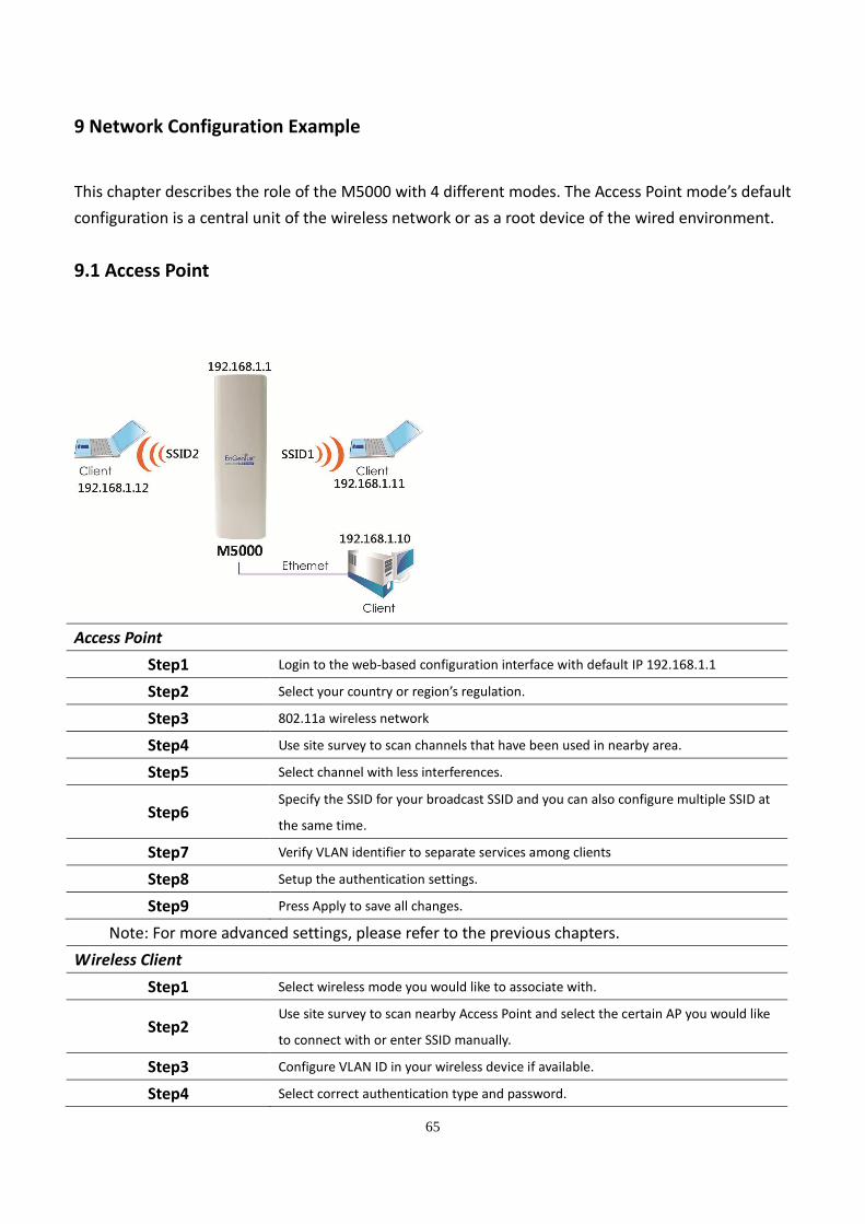
9.1 Access Point
Access Point
Step1 Login to the web-based configuration interface with default IP 192.168.1.1
Step2 Select your country or region’s regulation.
Step3 802.11a wireless network
Step4 Use site survey to scan channels that have been used in nearby area.
Step5 Select channel with less interferences.
Step6 Specify the SSID for your broadcast SSID and you can also configure multiple SSID at
the same time.
Step7 Verify VLAN identifier to separate services among clients
Step8 Setup the authentication settings.
Step9 Press Apply to save all changes.
Note: For more advanced settings, please refer to the previous chapters.
Wireless Client
Step1 Select wireless mode you would like to associate with.
Step2 Use site survey to scan nearby Access Point and select the certain AP you would like
to connect with or enter SSID manually.
Step3 Configure VLAN ID in your wireless device if available.
Step4 Select correct authentication type and password.
66
Auction: M5000’s Access Point Mode does not provide DHCP server so the Wireless Client IP address
must configure manually at the same subnet in Local Area Network.
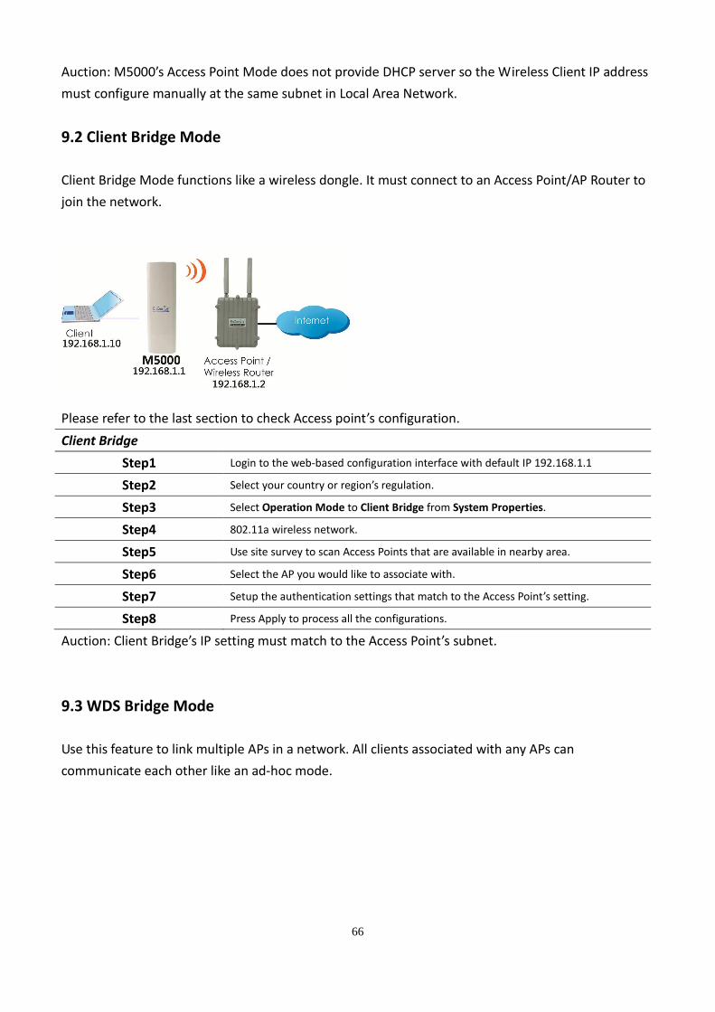
9.2 Client Bridge Mode
Client Bridge Mode functions like a wireless dongle. It must connect to an Access Point/AP Router to
join the network.
Please refer to the last section to check Access point’s configuration.
Client Bridge
Step1 Login to the web-based configuration interface with default IP 192.168.1.1
Step2 Select your country or region’s regulation.
Step3 Select Operation Mode to Client Bridge from System Properties.
Step4 802.11a wireless network.
Step5 Use site survey to scan Access Points that are available in nearby area.
Step6 Select the AP you would like to associate with.
Step7 Setup the authentication settings that match to the Access Point’s setting.
Step8 Press Apply to process all the configurations.
Auction: Client Bridge’s IP setting must match to the Access Point’s subnet.
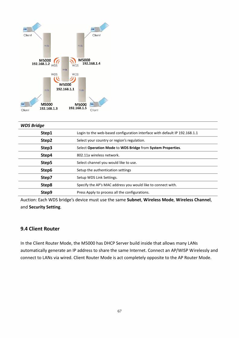
9.3 WDS Bridge Mode
Use this feature to link multiple APs in a network. All clients associated with any APs can
communicate each other like an ad-hoc mode.
67
WDS Bridge
Step1 Login to the web-based configuration interface with default IP 192.168.1.1
Step2 Select your country or region’s regulation.
Step3 Select Operation Mode to WDS Bridge from System Properties.
Step4 802.11a wireless network.
Step5 Select channel you would like to use.
Step6 Setup the authentication settings
Step7 Setup WDS Link Settings.
Step8 Specify the AP’s MAC address you would like to connect with.
Step9 Press Apply to process all the configurations.
Auction: Each WDS bridge’s device must use the same Subnet, Wireless Mode, Wireless Channel,
and Security Setting.
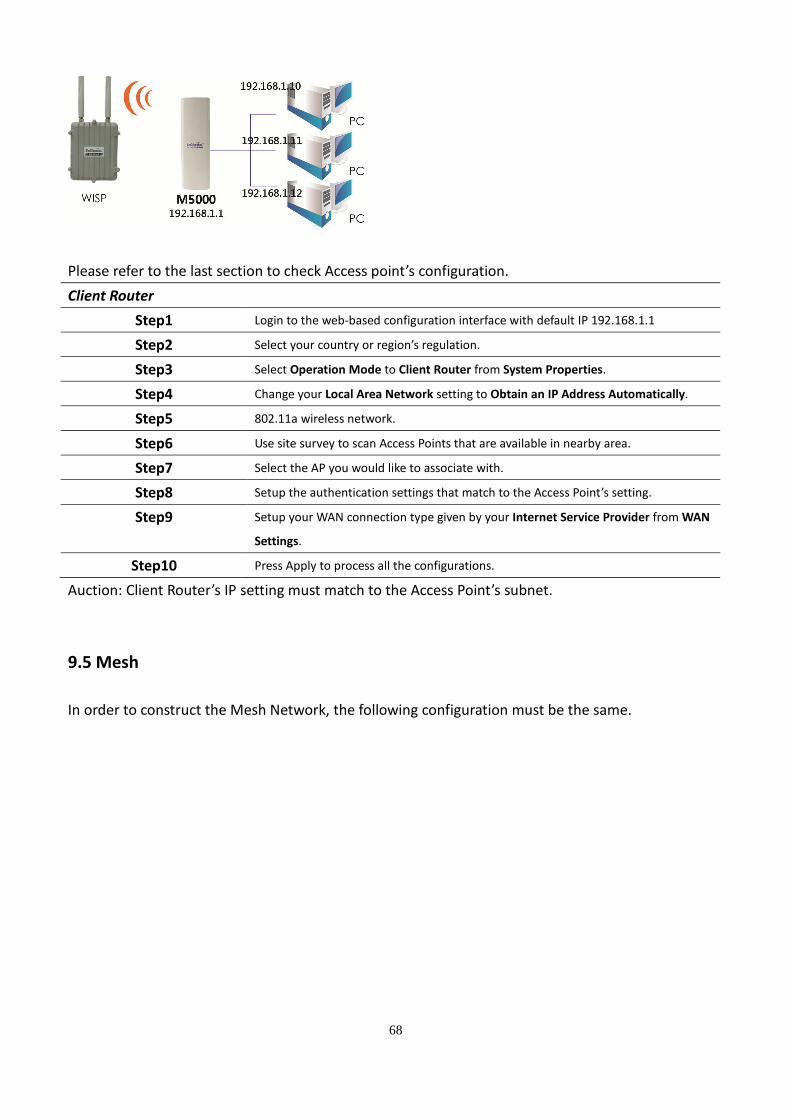
9.4 Client Router
In the Client Router Mode, the M5000 has DHCP Server build inside that allows many LANs
automatically generate an IP address to share the same Internet. Connect an AP/WISP Wirelessly and
connect to LANs via wired. Client Router Mode is act completely opposite to the AP Router Mode.
68
Please refer to the last section to check Access point’s configuration.
Client Router
Step1 Login to the web-based configuration interface with default IP 192.168.1.1
Step2 Select your country or region’s regulation.
Step3 Select Operation Mode to Client Router from System Properties.
Step4 Change your Local Area Network setting to Obtain an IP Address Automatically.
Step5 802.11a wireless network.
Step6 Use site survey to scan Access Points that are available in nearby area.
Step7 Select the AP you would like to associate with.
Step8 Setup the authentication settings that match to the Access Point’s setting.
Step9 Setup your WAN connection type given by your Internet Service Provider from WAN
Settings.
Step10 Press Apply to process all the configurations.
Auction: Client Router’s IP setting must match to the Access Point’s subnet.
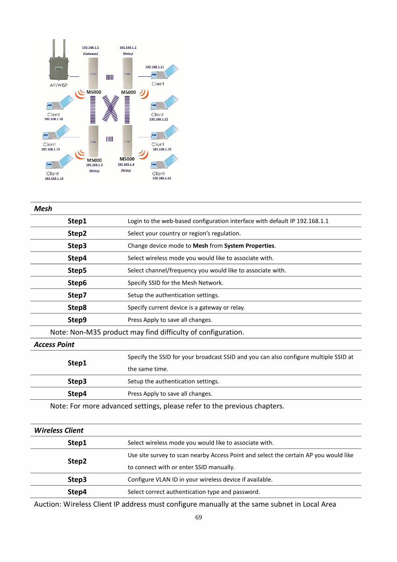
9.5 Mesh
In order to construct the Mesh Network, the following configuration must be the same.
69
Mesh
Step1 Login to the web-based configuration interface with default IP 192.168.1.1
Step2 Select your country or region’s regulation.
Step3 Change device mode to Mesh from System Properties.
Step4 Select wireless mode you would like to associate with.
Step5 Select channel/frequency you would like to associate with.
Step6 Specify SSID for the Mesh Network.
Step7 Setup the authentication settings.
Step8 Specify current device is a gateway or relay.
Step9 Press Apply to save all changes.
Note: Non-M35 product may find difficulty of configuration.
Access Point
Step1 Specify the SSID for your broadcast SSID and you can also configure multiple SSID at
the same time.
Step3 Setup the authentication settings.
Step4 Press Apply to save all changes.
Note: For more advanced settings, please refer to the previous chapters.
Wireless Client
Step1 Select wireless mode you would like to associate with.
Step2 Use site survey to scan nearby Access Point and select the certain AP you would like
to connect with or enter SSID manually.
Step3 Configure VLAN ID in your wireless device if available.
Step4 Select correct authentication type and password.
Auction: Wireless Client IP address must configure manually at the same subnet in Local Area

70
Network. Once a Gateway is connected to a WISP, all wireless clients and Mesh can retrieve IP
address automatically.
71
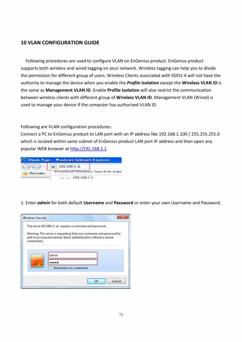
10 VLAN CONFIGURATION GUIDE
Following procedures are used to configure VLAN on EnGenius product. EnGenius product
supports both wireless and wired tagging on your network. Wireless tagging can help you to divide
the permission for different group of users. Wireless Clients associated with SSID1-4 will not have the
authority to manage the device when you enable the Profile Isolation except the Wireless VLAN ID is
the same as Management VLAN ID. Enable Profile Isolation will also restrict the communication
between wireless clients with different group of Wireless VLAN ID. Management VLAN (Wired) is
used to manage your device if the computer has authorized VLAN ID.
Following are VLAN configuration procedures:
Connect a PC to EnGenius product to LAN port with an IP address like 192.168.1.100 / 255.255.255.0
which is located within same subnet of EnGenius product LAN port IP address and then open any
popular WEB browser at http://192.168.1.1.
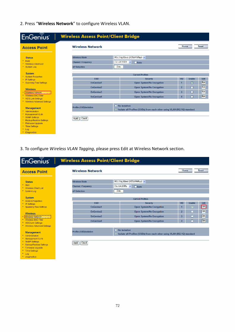
1. Enter admin for both default Username and Password or enter your own Username and Password.
72
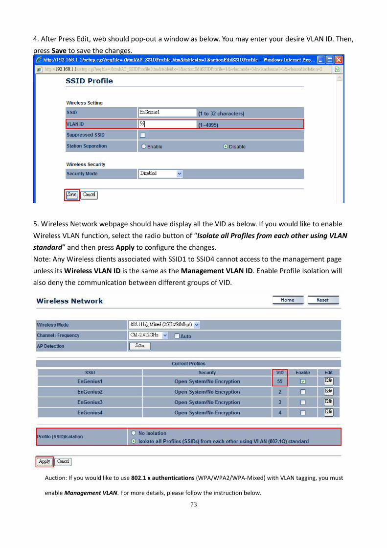
2. Press “Wireless Network” to configure Wireless VLAN.
3. To configure Wireless VLAN Tagging, please press Edit at Wireless Network section.
73
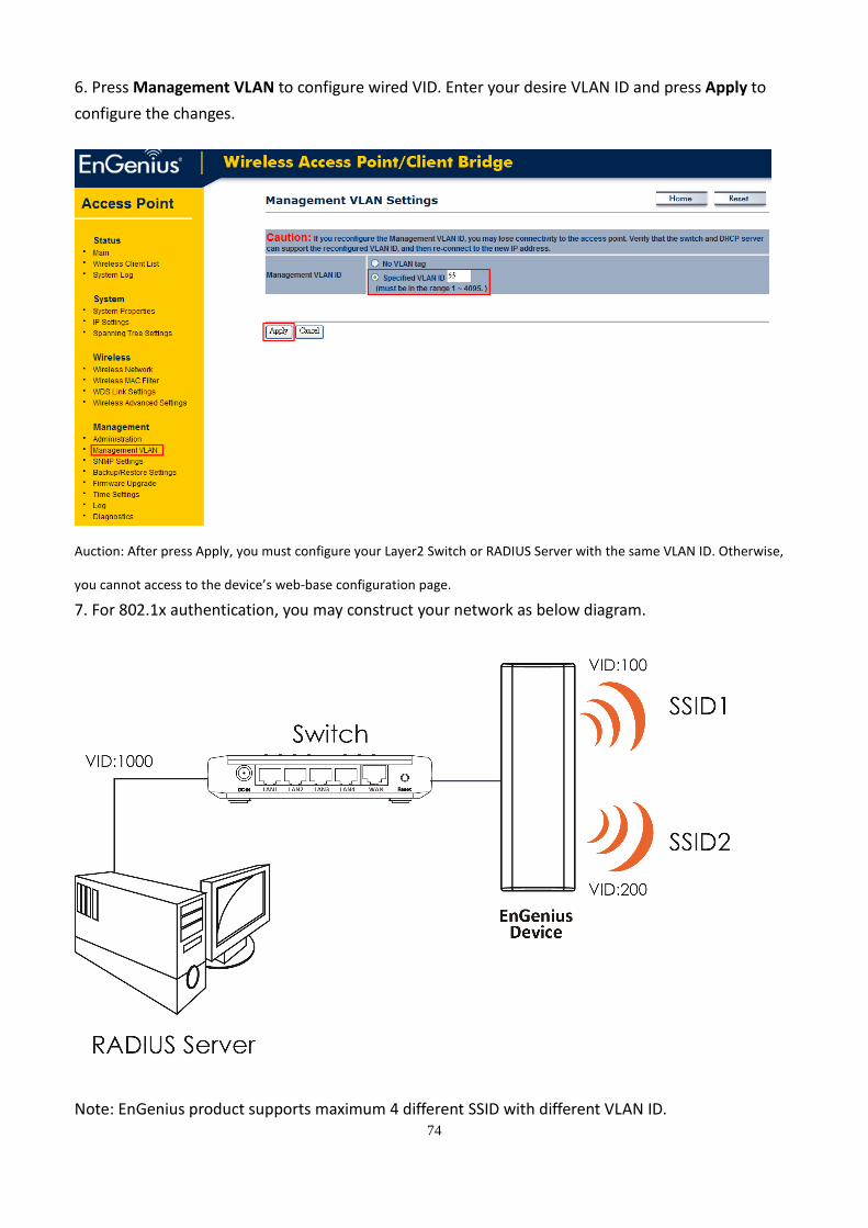
4. After Press Edit, web should pop-out a window as below. You may enter your desire VLAN ID. Then,
press Save to save the changes.
5. Wireless Network webpage should have display all the VID as below. If you would like to enable
Wireless VLAN function, select the radio button of “Isolate all Profiles from each other using VLAN
standard” and then press Apply to configure the changes.
Note: Any Wireless clients associated with SSID1 to SSID4 cannot access to the management page
unless its Wireless VLAN ID is the same as the Management VLAN ID. Enable Profile Isolation will
also deny the communication between different groups of VID.
Auction: If you would like to use 802.1 x authentications (WPA/WPA2/WPA-Mixed) with VLAN tagging, you must
enable Management VLAN. For more details, please follow the instruction below.
74
6. Press Management VLAN to configure wired VID. Enter your desire VLAN ID and press Apply to
configure the changes.
Auction: After press Apply, you must configure your Layer2 Switch or RADIUS Server with the same VLAN ID. Otherwise,
you cannot access to the device’s web-base configuration page.
7. For 802.1x authentication, you may construct your network as below diagram.
Note: EnGenius product supports maximum 4 different SSID with different VLAN ID.
75
Appendix A – FCC Interference Statement
Federal Communication Commission Interference Statement
This equipment has been tested and found to comply with the limits for a Class B digital device, pursuant to Part 15
of the FCC Rules. These limits are designed to provide reasonable protection against harmful interference in a
residential installation. This equipment generates, uses and can radiate radio frequency energy and, if not installed
and used in accordance with the instructions, may cause harmful interference to radio communications. However,
there is no guarantee that interference will not occur in a particular installation. If this equipment does cause
harmful interference to radio or television reception, which can be determined by turning the equipment off and on,
the user is encouraged to try to correct the interference by one of the following measures:
- Reorient or relocate the receiving antenna.
- Increase the separation between the equipment and receiver.
- Connect the equipment into an outlet on a circuit different from that
to which the receiver is connected.
- Consult the dealer or an experienced radio/TV technician for help.
FCC Caution: Any changes or modifications not expressly approved by the party responsible for compliance could
void the user's authority to operate this equipment.
This device complies with Part 15 of the FCC Rules. Operation is subject to the following two conditions: (1) This
device may not cause harmful interference, and (2) this device must accept any interference received, including
interference that may cause undesired operation.
IMPORTANT NOTE:
FCC Radiation Exposure Statement:
This equipment complies with FCC radiation exposure limits set forth for an uncontrolled environment. This
equipment should be installed and operated with minimum distance 20cm between the radiator & your body.
This transmitter must not be co-located or operating in conjunction with any other antenna or transmitter.
Top Related