


Languages
Pages
Legal


© 2015 Freescale Semiconductor, Inc. All rights reserved.
Wireless Coexistence in the 2.4 GHz Band
1. Introduction
The tests described in this document aim to determine
the effects of coexistence in the 2.4 GHz radio band of
the main wireless technologies that are using these
bands: IEEE Std. 802.15.4, IEEE Std. 802.11 (Wi-Fi),
and Bluetooth Smart.
The main purpose of the tests is to determine the
performance of an IEEE Std. 802.15.4 radio when
operating with Wi-Fi static and dynamic interference,
BLE interference, or combined Wi-Fi and BLE
interference. The IEEE Std. 802.15.4 radio used for
testing is the Freescale KW24 wireless MCU and the
Bluetooth Smart radio used for testing is the Freescale
KW40Z wireless MCU.
The test results determine the best and worst case
scenarios when different wireless technologies coexist.
These tests will enable you to:
• setup different wireless networks that may
coexist
• understand the effects of mutual
interference
• learn which channels are recommended for
use and which are not
• ensure proper distances between and correct
placement of wireless networks.
IEEEE Std. 802.15.4 defines 16 channels. The first
channel is channel 11 (with a central frequency of 2405
MHz) and the last channel is 26 (with a central
frequency of 2480 MHz). Each channel has a 2 MHz
bandwidth and a 5 MHz channel spacing.
Freescale Semiconductor, Inc. Document Number: AN5185
Application Note Rev. 0 , 09/2015
Contents
1. Introduction .................................................................... 1 2. Lab tests: IEEE 802.15.4 – IEEE 802.11n coexistence ...... 5
2.1. Energy scan .......................................................... 5 2.2. Packet Error Rate Test ........................................ 25
3. Acronyms and abbreviations .......................................... 38 4. Revision history ............................................................ 39

Introduction
Wireless Coexistence in the 2.4 GHz Band, Application Note, Rev. 0, 09/2015
2 Freescale Semiconductor, Inc.
IEEE Std. 802.11 defines a total of 14 channels however in contrast with IEEE 802.15.4, the channel
usage depends on the regulatory domain. IEEE Std. 802.11b recommends the use of non-overlapping
channels 1, 6, and 11 for North America and channels 1, 7, and 13 for Europe. Also, for North America
channels 13 and 14 are not used. See Figure 1.
IEEE Std. 802.15.4 is designed to ensure a reliable co-existence with other 2.4 GHz wireless
technologies and provides mechanisms that improve or enhance this co-existence. These mechanisms
can be found in Annex E of the IEEE 802.15.4 specification.
The following figure demonstrates that for both North America and Europe you can choose up to four
802.15.4 channels that are not overlapping the Wi-Fi channels.
Figure 1. IEEE 802.15.4 channel vs. non-overlapping IEEE 802.11b channels (US, Europe)
Coexistence among wireless technologies is dependent on three main factors:
• Frequency
• Time
• Space
If one (at least) of these three factors can be controlled, then coexistence can be achieved by:
• Frequency separation between networks’ operating channels
• Low occupancy of the channel
• Setting convenient distances between networks/nodes.
Introduction
Wireless Coexistence in the 2.4 GHz Band, Application Note, Rev. 0, 09/2015
Freescale Semiconductor, Inc. 3
However in real world deployment none of these three main factors can be fully controlled and therefore
the interference will always exist. The objective is to achieve an acceptable level of performance of
services delivered by the coexisting wireless technologies.
IEEE Std. 802.11n adds new features such as MIMO, channel bonding, and frame aggregation to
achieve higher throughput.
• MIMO uses multiple transmit and receive antennas to achieve higher throughputs. Spatial
multiplexing and spatial diversity are the most commonly used techniques. Data rates, the
modulation technique, and the number of streams are defined by IEEE Std. 802.11n by the
mean of the MCS index.
• Channel bonding: IEEE Std. 802.11n specifies a new mode that uses a 40MHz channel. This
channel is formed by two adjacent 20 MHz bands - therefore the PHY data rate can be
increased by up to 2 times.
• Frame aggregation is also used to increase the throughput. Every frame transmitted by an
IEEE 802.11n device has a significant amount of overhead (headers, frame fields,
interspacing frames, ACK frames) and this overhead can consume at higher data rates more
bandwidth than the payload frames. IEEE Std. 802.11n defines two frame aggregation types
to deal with this: MSDU aggregation and MPDU aggregation. Each aggregation type groups
several data frames into a single larger one. Since the management information has to be
specified only once per data frame, a higher throughput is therefore achieved.
The modulation type for both IEEE 802.11n and 802.11ac is OFDM. IEEE 802.11b and IEEE 802.15.4
use modulation type DSSS. IEEE 802.11g uses modulation type OFDM or DSSS. Due to this IEEE
802.11n can work more effectively with an IEEE 802.15.4 network. If possible the frame aggregation
(FA) level must be set to acceptable values. If the FA level is set too high, the Wi-Fi packets are longer
and the time to transmit the Wi-Fi packets is increased leaving too little time for the 802.15.4 network to
transmit its own packets (considering CCA enabled).
Figure 2. IEEE 802.11 n Power Spectral Density (OFDM modulation)

Lab tests: IEEE 802.15.4 – IEEE 802.11n coexistence
Wireless Coexistence in the 2.4 GHz Band, Application Note, Rev. 0, 09/2015
4 Freescale Semiconductor, Inc.
Figure 3. IEEE 802.15.4 Power Spectral Density (DSSS modulation)

Lab tests: IEEE 802.15.4 – IEEE 802.11n coexistence
Wireless Coexistence in the 2.4 GHz Band, Application Note, Rev. 0, 09/2015
Freescale Semiconductor, Inc. 5
2. Lab tests: IEEE 802.15.4 – IEEE 802.11n coexistence
2.1. Energy scan
An energy scan is performed on 802.15.4 radio channels when operating with 802.11 dynamic
interference.
2.1.1. Hardware components
For the Energy scan tests, the following items are used:
• Tescom TC-5916A shield box
• TP-Link wireless AP
• USB to ETH converter
• FRDM-K64F plus FRDM TWRPI shield with MCR20 radio transceiver
• TWR-KW24D512 tower card
• Manhattan USB hub
• Samsung Galaxy tablet (Android OS)
• Cables
• Power Supply for USB hub
All the items are placed inside the RF chamber during testing.
2.1.2. Software components
The firmware running on the TWR-KW24D512 tower card and the K64F+MCR20 setup is dependent
on the tests that are executed:
• SMAC Connectivity Test – energy scan test
The following PC software applications are used:
• Universal media server
• TeraTerm
• Octave
• Test Tool
• inSSIDer
On the Android tablet the following applications are used:
• Bubble uPNP
• Wi-Fi Analyzer
• Media Player
On the WiFi router the following is used:
• Openwrt firmware.

Lab tests: IEEE 802.15.4 – IEEE 802.11n coexistence
Wireless Coexistence in the 2.4 GHz Band, Application Note, Rev. 0, 09/2015
6 Freescale Semiconductor, Inc.
Figure 4. Energy detect hardware setup
2.1.3. System setup
The energy detect (energy scan) tests were performed within the RF chamber. Two 802.15.4 devices
were used (TWR-KW24D512 tower card and FRDM-K64F as well as a MCR20 radio).
On the PC, the Universal Media Server software is running a DLNA server. The laptop is connected to
the RF chamber via a USB cable. The cable is connected inside the chamber to a USB hub. A USB to
ETH converter is connected to the USB hub; the ETH cable is connected to the Wi-Fi access point.
The Android OS tablet is running a DLNA player application (Bubble uPNP) and is generating dynamic
traffic with the AP by playing a 1080p video. The two 802.15.4 devices are located at different positions
relative to the Wi-Fi physical setup and both nodes sequentially measure the energy on all 802.15.4
channels. The 802.11n channels used are: channel 1, channel 6, and channel 11. The 802.11n
transmission power auto-leveling algorithms are disabled and three transmission powers are used:
0 dBm, 12 dBm and 14 dBm.
2.1.4. Experimental results
The results are logged in files and then filtered and processed using octave scripts. The results are
averaged in plots to ensure that they are observed efficiently.

Lab tests: IEEE 802.15.4 – IEEE 802.11n coexistence
Wireless Coexistence in the 2.4 GHz Band, Application Note, Rev. 0, 09/2015
Freescale Semiconductor, Inc. 7
Figure 5. Experimental result 1
IEEE 802.11n, channel 1 (f = 2412 MHz), 0 dBm
Freedom K64F + MCR20 XCVR
Most affected IEEE 802.15.4 channels: 11,12,13,14
Lab tests: IEEE 802.15.4 – IEEE 802.11n coexistence
Wireless Coexistence in the 2.4 GHz Band, Application Note, Rev. 0, 09/2015
8 Freescale Semiconductor, Inc.
Figure 6. Experimental result 2
IEEE 802.11n, channel 1 (f = 2412 MHz), 0 dBm
TWR-KW24D512 Tower card
Most affected IEEE 802.15.4 channels: 11,12,13,14

Lab tests: IEEE 802.15.4 – IEEE 802.11n coexistence
Wireless Coexistence in the 2.4 GHz Band, Application Note, Rev. 0, 09/2015
Freescale Semiconductor, Inc. 9
Figure 7. Experimental results 3
IEEE 802.11n, channel 1 (f = 2412 MHz), +12 dBm
Freedom K64F + MCR20 XCVR
Most affected IEEE 802.15.4 channels: 11,12,13,14

Lab tests: IEEE 802.15.4 – IEEE 802.11n coexistence
Wireless Coexistence in the 2.4 GHz Band, Application Note, Rev. 0, 09/2015
10 Freescale Semiconductor, Inc.
Figure 8. Experimental results 4
IEEE 802.11n, channel 1 (f = 2412 MHz), +12 dBm
TWR-KW24D512 Tower card
Most affected IEEE 802.15.4 channels: 11,12,13,14

Lab tests: IEEE 802.15.4 – IEEE 802.11n coexistence
Wireless Coexistence in the 2.4 GHz Band, Application Note, Rev. 0, 09/2015
Freescale Semiconductor, Inc. 11
Figure 9. Experimental results 5
IEEE 802.11n, channel 1 (f = 2412 MHz), +14 dBm
Freedom K64F + MCR20 XCVR
Most affected IEEE 802.15.4 channels: 11,12,13,14

Lab tests: IEEE 802.15.4 – IEEE 802.11n coexistence
Wireless Coexistence in the 2.4 GHz Band, Application Note, Rev. 0, 09/2015
12 Freescale Semiconductor, Inc.
Figure 10. Experimental results 6
IEEE 802.11n, channel 1 (f = 2412 MHz), +14 dBm
TWR-KW24D512 Tower card
Most affected IEEE 802.15.4 channels: 11,12,13,14

Lab tests: IEEE 802.15.4 – IEEE 802.11n coexistence
Wireless Coexistence in the 2.4 GHz Band, Application Note, Rev. 0, 09/2015
Freescale Semiconductor, Inc. 13
Figure 11. Experimental results 7
IEEE 802.11n, channel 6 (f = 2437 MHz), 0 dBm
Freedom K64F + MCR20 XCVR
Most affected IEEE 802.15.4 channels: 16,17,18,19
Lab tests: IEEE 802.15.4 – IEEE 802.11n coexistence
Wireless Coexistence in the 2.4 GHz Band, Application Note, Rev. 0, 09/2015
14 Freescale Semiconductor, Inc.
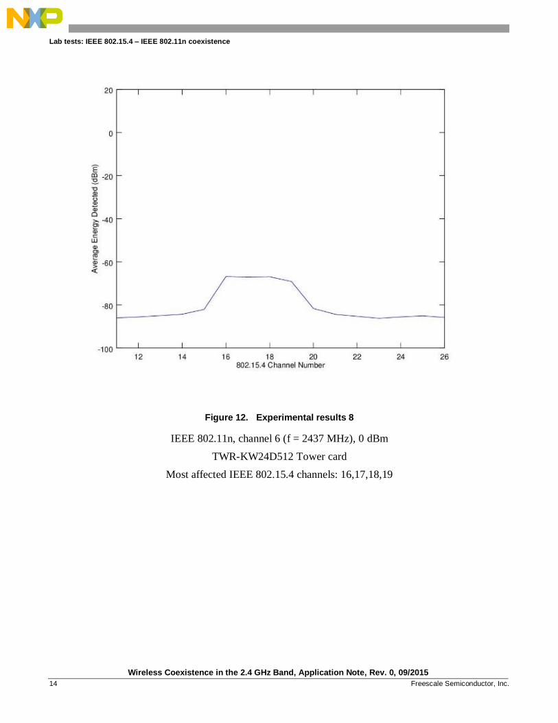
Figure 12. Experimental results 8
IEEE 802.11n, channel 6 (f = 2437 MHz), 0 dBm
TWR-KW24D512 Tower card
Most affected IEEE 802.15.4 channels: 16,17,18,19

Lab tests: IEEE 802.15.4 – IEEE 802.11n coexistence
Wireless Coexistence in the 2.4 GHz Band, Application Note, Rev. 0, 09/2015
Freescale Semiconductor, Inc. 15
Figure 13. Experimental results 9
IEEE 802.11n, channel 6 (f = 2437 MHz), +12 dBm
Freedom K64F + MCR20 XCVR
Most affected IEEE 802.15.4 channels: 16,17,18,19

Lab tests: IEEE 802.15.4 – IEEE 802.11n coexistence
Wireless Coexistence in the 2.4 GHz Band, Application Note, Rev. 0, 09/2015
16 Freescale Semiconductor, Inc.
Figure 14. Experimental results 10
IEEE 802.11n, channel 6 (f = 2437 MHz), +12 dBm
TWR-KW24D512 Tower card
Most affected IEEE 802.15.4 channels: 16,17,18,19

Lab tests: IEEE 802.15.4 – IEEE 802.11n coexistence
Wireless Coexistence in the 2.4 GHz Band, Application Note, Rev. 0, 09/2015
Freescale Semiconductor, Inc. 17
Figure 15. Experimental results 11
IEEE 802.11n, channel 6 (f = 2437 MHz), +14 dBm
Freedom K64F + MCR20 XCVR
Most affected IEEE 802.15.4 channels: 16,17,18,19

Lab tests: IEEE 802.15.4 – IEEE 802.11n coexistence
Wireless Coexistence in the 2.4 GHz Band, Application Note, Rev. 0, 09/2015
18 Freescale Semiconductor, Inc.
Figure 16. Experimental results 12
IEEE 802.11n, channel 6 (f = 2437 MHz), +14 dBm
TWR-KW24D512 Tower card
Most affected IEEE 802.15.4 channels: 16,17,18,19

Lab tests: IEEE 802.15.4 – IEEE 802.11n coexistence
Wireless Coexistence in the 2.4 GHz Band, Application Note, Rev. 0, 09/2015
Freescale Semiconductor, Inc. 19
Figure 17. Experimental results 13
IEEE 802.11n, channel 11 (f = 2462 MHz), 0 dBm
Freedom K64F + MCR20 XCVR
Most affected IEEE 802.15.4 channels: 21,22,23,24

Lab tests: IEEE 802.15.4 – IEEE 802.11n coexistence
Wireless Coexistence in the 2.4 GHz Band, Application Note, Rev. 0, 09/2015
20 Freescale Semiconductor, Inc.
Figure 18. Experimental results 14
IEEE 802.11n, channel 11 (f = 2462 MHz), 0 dBm
TWR-KW24D512 Tower card
Most affected IEEE 802.15.4 channels: 21,22,23,24

Lab tests: IEEE 802.15.4 – IEEE 802.11n coexistence
Wireless Coexistence in the 2.4 GHz Band, Application Note, Rev. 0, 09/2015
Freescale Semiconductor, Inc. 21
Figure 19. Experimental results 15
IEEE 802.11n, channel 11 (f = 2462 MHz), +12 dBm
Freedom K64F + MCR20 XCVR
Most affected IEEE 802.15.4 channels: 21,22,23,24

Lab tests: IEEE 802.15.4 – IEEE 802.11n coexistence
Wireless Coexistence in the 2.4 GHz Band, Application Note, Rev. 0, 09/2015
22 Freescale Semiconductor, Inc.
Figure 20. Experimental results 16
IEEE 802.11n, channel 11 (f = 2462 MHz), +12 dBm
TWR-KW24D512 Tower card
Most affected IEEE 802.15.4 channels: 21,22,23,24

Lab tests: IEEE 802.15.4 – IEEE 802.11n coexistence
Wireless Coexistence in the 2.4 GHz Band, Application Note, Rev. 0, 09/2015
Freescale Semiconductor, Inc. 23
Figure 21. Experimental results 17
IEEE 802.11n, channel 11 (f = 2462 MHz), +14 dBm
Freedom K64F + MCR20 XCVR
Most affected IEEE 802.15.4 channels: 21,22,23,24

Lab tests: IEEE 802.15.4 – IEEE 802.11n coexistence
Wireless Coexistence in the 2.4 GHz Band, Application Note, Rev. 0, 09/2015
24 Freescale Semiconductor, Inc.
Figure 22. Experimental results 18
IEEE 802.11n, channel 11 (f = 2462 MHz), +14 dBm
TWR-KW24D512 Tower card
Most affected IEEE 802.15.4 channels: 21,22,23,24
2.1.5. Conclusions:
• The IEEE 802.11 energy is seen as additive white Gaussian noise by the IEEE 802.15.4
radios.
• The IEEE 802.15.4 radio sensitivity is altered about 20 dBm on the converging frequencies
(overlapping channels).
• RSSI/LQI is a poor indicator of link quality in noisy environments.
• If CSMA-CA is enabled, then the CCA threshold must be set taking into consideration the
interference level of the coexisting networks.
Lab tests: IEEE 802.15.4 – IEEE 802.11n coexistence
Wireless Coexistence in the 2.4 GHz Band, Application Note, Rev. 0, 09/2015
Freescale Semiconductor, Inc. 25
2.2. Packet error rate test
A packet error rate test is performed on 802.15.4 radio channels when operating with 802.11 dynamic
interference
2.2.1. Hardware components:
For the packet error rate tests, the following items were used:
• Tescom TC-5916A Shield Box
• TP-Link wireless AP
• USB to ETH converter
• 2 x TWR-KW24D512 tower card
• Manhattan USB hub
• Samsung Galaxy tablet (Android OS)
• Samsung Galaxy S3 smartphone (Android OS)
• Cables
• Power Supply for USB hub
All items are placed inside the RF chamber during testing.
2.2.2. Software components:
For the two TWR-KW24D512 tower card the following firmware has been used:
• 802.15.4_MAC2006_KW24D512_CoexistenceTool.srec
On the PC software side, the following applications have been used:
• Test Tool with Coexistence Tool
• Octave
• TeraTerm
• Microsoft Excel 2013
• inSSIDer
• jPerf
On the Android tablet the following applications are used:
• iPerf Server
• Wi-Fi Analyzer
• Terminal Emulator
On the Android smartphone the following applications are used:
• iPerf Client
• Wi-Fi Analyzer
• Terminal Emulator

Lab tests: IEEE 802.15.4 – IEEE 802.11n coexistence
Wireless Coexistence in the 2.4 GHz Band, Application Note, Rev. 0, 09/2015
26 Freescale Semiconductor, Inc.
On the Wi-Fi router the following is used:
• OpenWrt firmware.
The hardware setup can be seen in the following figure:
Figure 23. PER Tests HW setup
2.2.3. System setup
In Figure 23 the red cable represents the ETH cable and the blue ones represent USB cables.
The following PER test was performed: PER test on overlapping channels, Wi-Fi channel 11 (2.462
GHz) and 802.15.4 channels 21 (2.455 GHz), 22(2.460 GHz), 23(2.465 GHz) and 24 (2.470 GHz) at
constant Wi-Fi transmission power level but different throughputs, constant 802.15.4 transmission
power and packet length, CCA enabled. A test with the same Wi-Fi configurations (same constant
power and channel with the same throughput values) was done with a non-overlapping channel that is
close to one of the overlapping channels (802.15.4 channel 20 (2.450 GHz)) because the energy
detection tests showed that the Wi-Fi signal was detected as noise on other channels besides the
overlapping ones.
The Wi-Fi router provided an USB port where the smart phone was connected and a network connection
between them was established using USB tethering; the Android tablet was connected to the Wi-Fi

Lab tests: IEEE 802.15.4 – IEEE 802.11n coexistence
Wireless Coexistence in the 2.4 GHz Band, Application Note, Rev. 0, 09/2015
Freescale Semiconductor, Inc. 27
router over the air. In the Wi-Fi router the two networks (on Wi-Fi and USB) were bridged and a
network connection between the smartphone and the tablet was established. A client-server connection
was established between the two devices using iPerf Android App. The OpenWrt firmware on the Wi-Fi
router offers more control of the Wi-Fi traffic (possibility to control the router’s Wi-Fi transceiver
output power and the Wi-Fi channel) so it is preferred that the Wi-Fi traffic comes from the router to the
tablet.
Data is transferred in UDP datagrams at different throughputs (0.5, 1, 5, 10, 15, 20, 25, 30, 35, 40, and
45 Mbits/sec) from the iPerf client application on the smartphone through USB tethering to the router.
The router forwards the UDP datagrams to the tablet via Wi-Fi at constant power and on a fixed channel
(Wi-Fi channel 11 at 2.462 GHz).
With this setup, a stable and controlled level of interference was achieved for the IEEE 802.15.4
network.
On the IEEE 802.15.4 side we have two KW24-D512 TOWER boards running the
802.15.4_MAC2006_KW24D512_CoexistenceTool.srec firmware which was downloaded from Test
Tool.
The Coexistence Tool from the Test Tool software was used to configure and control the boards and to
gather the test data.
The boards were configured to send 5000 packets from one to the other at a 5ms rate with MAC
acknowledge request set to true, with 4 retry attempts, at nominal output power, with 100 B bytes
payload and a fixed base channel for each test (there is one test for each of the following channels: 20,
21, 22, 23, and 24, forming a test suite). Each test suite was repeated for each Wi-Fi bandwidth value
mentioned earlier in the document.
The Coexistence Tool provided PER values and a time graph showing when a packet was successfully
sent or was lost. Based on this graph and the logs from iPerf it was possible to eliminate statistically
incorrect data in order to have more accurate results (for example the graph mostly showed dropped
packets and there was an interval with 0% PER, if the logs in iPerf showed that the Wi-Fi bandwidth
fluctuated significantly that specific data was eliminated from the results and the PER was recalculated).
The data from Test Tool was exported to an Excel spreadsheet and then transferred to an Octave.m file,
where it was processed and plotted.
The first set of test were run with the router’s output power set to 14 dBm (25 mW) and the second set
of tests were run with the router’s output power set to 0dBm (1mW). The distance between boards was
20–25 cm. The distance between one of the boards and the router was 5 cm and the distance between the
same board and the tablet was approximately 5 cm.

Lab tests: IEEE 802.15.4 – IEEE 802.11n coexistence
Wireless Coexistence in the 2.4 GHz Band, Application Note, Rev. 0, 09/2015
28 Freescale Semiconductor, Inc.
2.2.4. Experimental results
Figure 24. PER results: test case 1
802.15.4 PER results. The following parameters were used:
• Wifi channel: 11 (2.462 GHz)
• Wifi Tx power: 14 dBm (25 mW)
• 802.15.4 channel: 20
• 802.15.4 payload size: 100 B

Lab tests: IEEE 802.15.4 – IEEE 802.11n coexistence
Wireless Coexistence in the 2.4 GHz Band, Application Note, Rev. 0, 09/2015
Freescale Semiconductor, Inc. 29
Figure 25. PER results: test case 2
802.15.4 PER results. The following parameters were used:
• Wifi channel: 11 (2.462 GHz)
• Wifi Tx power: 14 dBm (25 mW)
• 802.15.4 channel: 21
• 802.15.4 payload size: 100 B
Lab tests: IEEE 802.15.4 – IEEE 802.11n coexistence
Wireless Coexistence in the 2.4 GHz Band, Application Note, Rev. 0, 09/2015
30 Freescale Semiconductor, Inc.
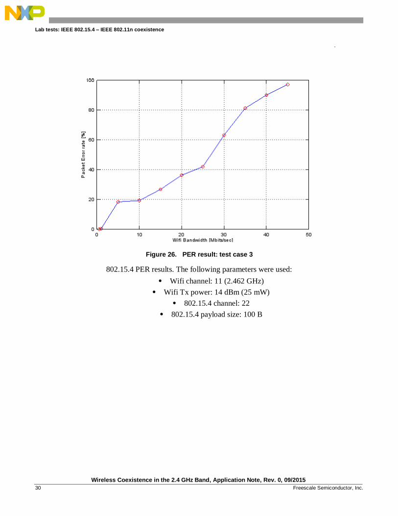
Figure 26. PER result: test case 3
802.15.4 PER results. The following parameters were used:
• Wifi channel: 11 (2.462 GHz)
• Wifi Tx power: 14 dBm (25 mW)
• 802.15.4 channel: 22
• 802.15.4 payload size: 100 B

Lab tests: IEEE 802.15.4 – IEEE 802.11n coexistence
Wireless Coexistence in the 2.4 GHz Band, Application Note, Rev. 0, 09/2015
Freescale Semiconductor, Inc. 31
Figure 27. PER results: test case 4
802.15.4 PER results. The following parameters were used:
• Wifi channel: 11 (2.462 GHz)
• Wifi Tx power: 14 dBm (25 mW)
• 802.15.4 channel: 23
• 802.15.4 payload size: 100 B

Lab tests: IEEE 802.15.4 – IEEE 802.11n coexistence
Wireless Coexistence in the 2.4 GHz Band, Application Note, Rev. 0, 09/2015
32 Freescale Semiconductor, Inc.
Figure 28. PER results: test case 5
802.15.4 PER results. The following parameters were used:
• Wifi channel: 11 (2.462 GHz)
• Wifi Tx power: 14 dBm (25 mW)
• 802.15.4 channel: 24
• 802.15.4 payload size: 100 B

Lab tests: IEEE 802.15.4 – IEEE 802.11n coexistence
Wireless Coexistence in the 2.4 GHz Band, Application Note, Rev. 0, 09/2015
Freescale Semiconductor, Inc. 33
Figure 29. PER results: test case 6
802.15.4 PER results. The following parameters were used:
• Wifi channel: 11 (2.462 GHz)
• Wifi Tx power: 0 dBm (1 mW)
• 802.15.4 channel: 20
• 802.15.4 payload size: 100 B

Lab tests: IEEE 802.15.4 – IEEE 802.11n coexistence
Wireless Coexistence in the 2.4 GHz Band, Application Note, Rev. 0, 09/2015
34 Freescale Semiconductor, Inc.
Figure 30. PER results: test case 7
802.15.4 PER results. The following parameters were used:
• Wifi channel: 11 (2.462 GHz)
• Wifi Tx power: 0 dBm (1 mW)
• 802.15.4 channel: 21
• 802.15.4 payload size: 100 B

Lab tests: IEEE 802.15.4 – IEEE 802.11n coexistence
Wireless Coexistence in the 2.4 GHz Band, Application Note, Rev. 0, 09/2015
Freescale Semiconductor, Inc. 35
Figure 31. PER results: test case 8
802.15.4 PER results. The following parameters were used:
• Wifi channel: 11 (2.462 GHz)
• Wifi Tx power: 0 dBm (1 mW)
• 802.15.4 channel: 22
• 802.15.4 payload size: 100 B

Lab tests: IEEE 802.15.4 – IEEE 802.11n coexistence
Wireless Coexistence in the 2.4 GHz Band, Application Note, Rev. 0, 09/2015
36 Freescale Semiconductor, Inc.
Figure 32. PER results: test case 9
802.15.4 PER results. The following parameters were used:
• Wifi channel: 11 (2.462 GHz)
• Wifi Tx power: 0 dBm (1 mW)
• 802.15.4 channel: 23
• 802.15.4 payload size: 100 B
Lab tests: IEEE 802.15.4 – IEEE 802.11n coexistence
Wireless Coexistence in the 2.4 GHz Band, Application Note, Rev. 0, 09/2015
Freescale Semiconductor, Inc. 37
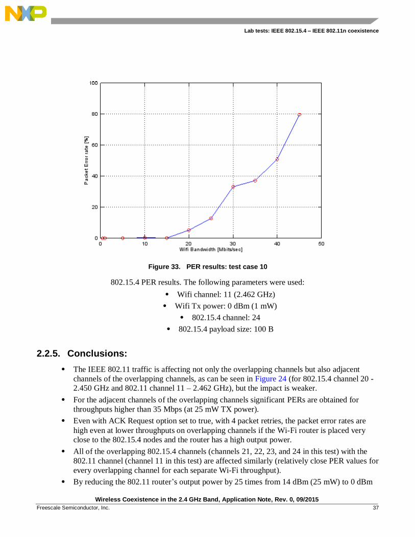
Figure 33. PER results: test case 10
802.15.4 PER results. The following parameters were used:
• Wifi channel: 11 (2.462 GHz)
• Wifi Tx power: 0 dBm (1 mW)
• 802.15.4 channel: 24
• 802.15.4 payload size: 100 B
2.2.5. Conclusions:
• The IEEE 802.11 traffic is affecting not only the overlapping channels but also adjacent
channels of the overlapping channels, as can be seen in Figure 24 (for 802.15.4 channel 20 -
2.450 GHz and 802.11 channel 11 – 2.462 GHz), but the impact is weaker.
• For the adjacent channels of the overlapping channels significant PERs are obtained for
throughputs higher than 35 Mbps (at 25 mW TX power).
• Even with ACK Request option set to true, with 4 packet retries, the packet error rates are
high even at lower throughputs on overlapping channels if the Wi-Fi router is placed very
close to the 802.15.4 nodes and the router has a high output power.
• All of the overlapping 802.15.4 channels (channels 21, 22, 23, and 24 in this test) with the
802.11 channel (channel 11 in this test) are affected similarly (relatively close PER values for
every overlapping channel for each separate Wi-Fi throughput).
• By reducing the 802.11 router’s output power by 25 times from 14 dBm (25 mW) to 0 dBm

Acronyms and abbreviations
Wireless Coexistence in the 2.4 GHz Band, Application Note, Rev. 0, 09/2015
38 Freescale Semiconductor, Inc.
(1 mW), the PER has been significantly reduced. It can be seen that for the overlapping
channels, at throughputs equal or less than 15 Mbps, the PER is negligible and at about
20 Mbps the PER is very small. The neighboring adjacent channels are noticeably affected
only when the throughput is over 30 Mbps.
3. Acronyms and abbreviations
Acronym / Term Definition
BLE Bluetooth Low Energy (Bluetooth Smart)
WLAN Wireless Local Area Network
WPAN Wireless Personal Area Network
WBAN Wireless Body Area Network
ISM Industrial scientific medical
IEEE Institute of Electrical and Electronics Engineers
IP Internet Protocol
CCA Clear Channel Assessment
SiP System in Package
DUT Device under Test
MAC Simple MAC
MAC Medium Access Control
CSMA-CA Carrier Sense Multiple Access – Collision Avoidance
PER Packet Error Rate
MCU Microcontroller Unit
AP Access Point
XCVR Transceiver

Revision history
Wireless Coexistence in the 2.4 GHz Band, Application Note, Rev. 0, 09/2015
Freescale Semiconductor, Inc. 39
4. Revision history
This table provides a revision history for this document.
Table 1. Revision history
Revision number Date Substantive changes
0 09/2015 Initial release

Document Number: AN5185 Rev. 0
09/2015
How to Reach Us:
Home Page:
freescale.com
Web Support:
freescale.com/support
Information in this document is provided solely to enable system and software implementers to
use Freescale products. There are no express or implied copyright licenses granted hereunder to
design or fabricate any integrated circuits based on the information in this document.
Freescale reserves the right to make changes without further notice to any products herein.
Freescale makes no warranty, representation, or guarantee regarding the suitability of its
products for any particular purpose, nor does Freescale assume any liability arising out of the
application or use of any product or circuit, and specifically disclaims any and all liability,
including without limitation consequential or incidental damages. “Typical” parameters that may
be provided in Freescale data sheets and/or specifications can and do vary in different
applications, and actual performance may vary over time. All operating parameters, including
“typicals,” must be validated for each customer application by customer's technical experts.
Freescale does not convey any license under its patent rights nor the rights of others. Freescale
sells products pursuant to standard terms and conditions of sale, which can be found at the
following address: freescale.com/SalesTermsandConditions.
Registered trademarks: Freescale, the Freescale logo, are trademarks of Freescale Semiconductor,
Inc., Reg. U.S. Pat. & Tm. Off. ARM, ARM Powered and Cortex are registered trademarks of
ARM Limited (or its subsidiaries) in the EU and/or elsewhere. All rights reserved.
IEEE Stds are registered trademarks of the Institute of Electrical and Electronics Engineers, Inc.
(IEEE). This product is not endorsed or approved by the IEEE.
© 2015 Freescale Semiconductor, Inc.
.
Top Related