


Languages
Pages
Legal


Change for life
Wired Controller XK60
Commercial Air ConditionersOwner's Manual
Thank you for choosing Commercial Air Conditioners, please read thisowner’s manual carefully before operation and retain it for future reference.GREE reserves the right to interpret this manual which will be subject to any change due to product improvement without further notice.GREE Electric Appliances, Inc. of Zhuhai reserves the final right to interpret this manual.

User NoticePlease carefully read this manual before installation and use of this product
◆ Thanks for choosing GREE duct type air conditioners. Please read this manual carefully before operating this product and keep it properly for future reference. In addition, please take notice of the symbols below.
WARNING! This mark indicates procedures which, if improperly performed, might lead to the death or serious injury of the user.
CAUTION! This mark indicates procedures which, if improperly performed, might possibly result in personal harm to the user, or damage to property.
CAUTION!
(1). Do not install the wired controller in the damp place or under direct sunlight.
(2). Do not beat, toss, or frequently assemble/disassemble the wired controller.
(3). Do not operate the wired controller with wed hands and never let any liquid flow into it.
(4). Do not install or remove the wired controller by yourself. If necessary, please contact the after-sales serviceman.
(5). This wired controller is applicable to various kinds of air conditioners, while some specific functions unavailable to the duct type air conditioners will not be covered in this manual.
(6). Before operating the air conditioner, please read this manual carefully and keep it properly for future reference.
1 Introduction to the Wired Controller ................................................................. 1
1.1 Appearance and LCD Icons ....................................................................... 1
1.2 Introduction to the LCD Icons ..................................................................... 2
2 Press Buttons .................................................................................................. 4
2.1 Buttons ....................................................................................................... 4
2.2 Instruction to the Function of Press Buttons ............................................... 4
3 OPERATION INSTRUCTION ......................................................................... 5
3.1 On/off .......................................................................................................... 5
3.2 Mode Setting .............................................................................................. 5
3.3 Temperature Setting ................................................................................... 6
3.4 Fan Speed Setting ...................................................................................... 6
3.5 Right and Left Swing .................................................................................. 7
3.6 Up and Down Swing ................................................................................... 8
3.7 Timer Setting .............................................................................................. 8
3.8 Air Exchange Setting .................................................................................. 9
3.9 Sleep Setting ............................................................................................ 11
3.10 Health Setting ........................................................................................ 13
3.11 I-Demand Setting .................................................................................... 13
3.12 Vacation Setting ..................................................................................... 14
3.13 Turbo Function Setting ........................................................................... 15
3.14 SAVE Function Setting ........................................................................... 16
Contents

3.15 E-HEATER Setting .................................................................................18
3.16 Blow Function Setting .............................................................................18
3.17 Filter Setting ...........................................................................................19
3.18 Quiet Function Setting .......................................................................21
3.19 Ultra-Dry Setting ....................................................................................22
3.20 Other Functions ......................................................................................22
4 Installation of the Wired Controller ...............................................................24
4.1 Standard Parts .........................................................................................24
4.2 Installation Location and Installation Requirements ................................25
4.3 How to Install the Wired Controller ...........................................................25
4.4 How to Remove the Wired Controller .......................................................26
5 Error Display .................................................................................................26

Wired Controller XK60
1
1 Introduction to the Wired Controller
Fig.1 Appearance of the Wired Controller
1.1 Appearance and LCD Icons
Fig.2 Appearance of the LCD

Wired Controller XK60
2
1.2 Introduction to the LCD IconsTable 1
No. Icons Introduction
1 Left and right swing function
2 Up and down swing function
3 Air exchange function
4 Sleep function
5 Auto mode
6 COOL mode
7 DRY mode
8 FAN mode
9 HEAT mode
10 Health function
11 I-Demand function
12 Vacation function
13 Status display of master and slave wired controller
14Shield functionThe button operation, temperature setting, "On/Off" operation, "Mode" setting, and "Save" setting are disabled.
15 Fan speed
16Memory functionThe unit will resume the original setting state after power recovery.
17 Turbo function
18 Energy-saving function
19 Ambient/setting temperature

Wired Controller XK60
3
20 Electric heater
21 Blow function
22 Defrosting function
23 Filter cleaning
24 Timer Setting
25 Keycard control / Detected status sensed by human body
26 Quiet function
27 Lock function

Wired Controller XK60
4
2 Press Buttons
2.1 Buttons
Fig.3 Press Buttons
2.2 Instruction to the Function of Press ButtonsTable 2
No. Press Buttons Function Introduction
1 Enter/Cancel ① .Function selection and canceling;② .Press it for 5s to enquiry the outdoor and indoor ambient temperature.
2 ▲① .Running temperature setting of indoor unit, range :16~30°C② .Timer setting, range:0.5-24hr③ .Air function setting④ .Save setting⑤ .Clean setting
6 ▼
3 FanSelect fan speed from high, mid-high, middle, mid-low, low and auto levels.
4 Mode Selection of the COOL, HEAT, FAN or DRY mode.
5 FunctionSwitchover among these functions of SWING/AIR/SLEEP/HEALTH/I-DEMAND/VACATION/TURBO/SAVE/E-HEATER/BLOW/QUIET
7 Timer Timer setting
8 On/Off Turn on/off indoor unit
4 mode and 2 ▲
Memory
Press Mode and ▲ at the same time for 5s under the OFF state of the unit to activate/deactivate memory function (If memory is set, indoor unit will resume original setting state after power recovery. If not, indoor unit is defaulted to be OFF after power recovery. Memory function is defaulted to be ON)
2 ▲and 6 ▼
Lock
Under the ON state of the unit without any malfunction or under the OFF state of the unit, press ▲and ▼ buttons at the same time for 5s to go to the lock state. In this case, any other buttons won’t respond the press. Repress ▲ and ▼ again for 5s to quit the lock state.
4 modeand 6 ▼
°F/°CUnder the OFF state of the unit, press the Mode and ▼ at the same time for 5s to switch the temperature scale between Celsius and Fahrenheit.
Wired Controller XK60
5
3 OPERATION INSTRUCTION
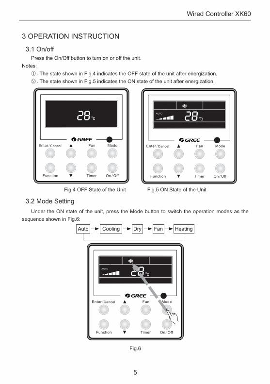
3.1 On/offPress the On/Off button to turn on or off the unit.
Notes: ① .The state shown in Fig.4 indicates the OFF state of the unit after energization.② .The state shown in Fig.5 indicates the ON state of the unit after energization.
Fig.4 OFF State of the Unit Fig.5 ON State of the Unit
3.2 Mode SettingUnder the ON state of the unit, press the Mode button to switch the operation modes as the
sequence shown in Fig.6:
Auto Cooling Dry Fan Heating
Fig.6

Wired Controller XK60
6
3.3 Temperature SettingPress ▲ or ▼button to increase or decrease setting temperature under on-state of the unit. If
press either of them continuously, temperature will be increased or decreased by 1°C every 0.5s.In Cooling, Dry, Fan and Heating mode, temperature setting range is 16°C~30°C.In Auto mode, the setting temperature is un-adjustable.As shown in Fig.7:
Fig.7 Temperature Setting
3.4 Fan Speed SettingPress Fan button, fan speed of indoor unit will change as the sequence shown in Fig.8:
Low Mid-low Mid-highMiddle High Super-high Auto
Fig.8 Fan Speed Setting

Wired Controller XK60
7
3.5 Right and Left SwingUnder the ON state of unit, press the Function button to select the “Right and Left Swing”
function option and then press the Enter/Cancel button to activate it.When the Swing function is activated, press the Function button to select the "Right and Left
Swing" function option and then press the Enter/Cancel button to deactivate it.Right and Left Swing function setting is as shown in Fig.9.
Unit On, no left-right swing Press “Function” button to setleft-right swing function
Press “Enter/Cancel” button to activate left-right swing function
Press “Function” button to set left-right swing function
Press “Enter/Cancel” button to cancel left-right swing function
Fig.9 Right and Left Swing Setting
Wired Controller XK60
8
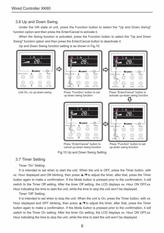
3.6 Up and Down SwingUnder the ON state of unit, press the Function button to select the "Up and Down Swing"
function option and then press the Enter/Cancel to activate it.When the Swing function is activated, press the Function button to select the "Up and Down
Swing" function option and then press the Enter/Cancel button to deactivate it.Up and Down Swing function setting is as shown in Fig.10.
Unit On, no up-down swing Press “Function” button to set up-down swing function
Press “Enter/Cancel” button to activate up-down swing function
Press “Function” button to set up-down swing function
Press “Enter/Cancel” button to cancel up-down swing function
Fig.10 Up and Down Swing Setting
3.7 Timer SettingTimer “On” Setting:It is intended to set when to start the unit. When the unit is OFF, press the Timer button, with
xx. Hour displayed and ON blinking, then press ▲/▼to adjust the timer, after that, press the Timer button again to make a confirmation. If the Mode button is pressed prior to the confirmation, it will switch to the Timer Off setting. After the timer Off setting, the LCD displays xx. Hour ON OFF,xx. Hour indicating the time to start the unit, while the time to stop the unit won’t be displayed.
Timer “Off” Setting:It is intended to set when to stop the unit. When the unit is On, press the Timer button, with xx.
Hour displayed and OFF blinking, then press ▲/▼to adjust the timer, after that, press the Timer button again to make a confirmation. If the Mode button is pressed prior to the confirmation, it will switch to the Timer On setting. After the timer On setting, the LCD displays xx. Hour ON OFF,xx. Hour indicating the time to stop the unit, while the time to start the unit won’t be displayed.

Wired Controller XK60
9
Cancellation of Timer Setting: The timer setting can be canceled by press “Timer”. Then , xx. Hour won’t be displayed.
Timer Setting under the ON state of the Unit is as shown in Fig.11:
Unit On, no timer function Press “Timer” button to set timer off adjust timer time
Press “Mode” button to set timer onadjust timer time
Press “timer” button to activate timer function
Fig.11 Timer Setting under the ON state of the UnitTimer range: 0.5-24hr. Every press of the ▲ or ▼ button will make the setting time increased or
decreased by 0.5hr.If press either of them continuously, the setting time will automatically increase/ decrease by 0.5hr every 0.5s.Notes:
① .When Timer On and Timer Off both are set, the displayed time is the Timer On setting for the unit under the OFF state , or is the timer Off setting for the unit under the ON state .
② .Timer On setting starts when the unit under the ON state is turned off; Timer Off setting starts when the unit under the OFF state is turned on.
3.8 Air Exchange SettingHow to activate the air exchange function:Under the ON state of the unit, press the Function button to select the “AIR” function, with
the function symbol flashing, and then press ▲ or ▼ to adjust the “AIR” type, after that, press the Enter/Cancel button to activate this function. When this function is activated, the symbol will be displayed. Type 1 is the defaulted “AIR” type.
There are 10 “AIR” function types , but only 1-2 types are for the wireless remote controller.

Wired Controller XK60
10
1――The unit continuously runs for 60min, and fresh air valve runs for 6 min.2――The unit continuously runs for 60min, and fresh air valve runs for 12 min.3――The unit continuously runs for 60min, and fresh air valve runs for 18 min.4――The unit continuously runs for 60min, and fresh air valve runs for 2 4 min.5――The unit continuously runs for 60min, and fresh air valve runs for 30 min.6――The unit continuously runs for 60min, and fresh air valve runs for 36 min.7――The unit continuously runs for 60min, and fresh air valve runs for 42 min.8――The unit continuously runs for 60min, and fresh air valve runs for 48 min.9――The unit continuously runs for 60min, and fresh air valve runs for 54 min.10――The unit continuously runs for 60min, and fresh air valve always runs.How to deactivate the air exchange function:When the “Air” function is activated, it can be deactivated in the way by firstly pressing the
Function button to select the “Air” function option with the “Air” symbol flashing, and then pressing the Enter/Cancel button with the “Air” symbol disappeared.
Air Exchange setting is shown as in Fig.12:
Unit On, no Air function Press “Function” button to set air function adjust air mode
Press “Enter/Cancel” button to activate air function
Press “Function” button to set air function
Press “Enter/Cancel” button to cancel air function
Fig.12 Air Exchange Setting
Wired Controller XK60
11
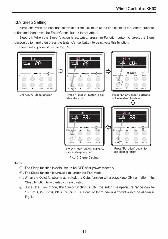
3.9 Sleep SettingSleep on: Press the Function button under the ON state of the unit to select the “Sleep” function
option and then press the Enter/Cancel button to activate it.Sleep off: When the Sleep function is activated, press the Function button to select the Sleep
function option and then press the Enter/Cancel button to deactivate this function. Sleep setting is as shown in Fig.13 :
Unit On, no Sleep function Press “Function” button to set sleep function
Press “Enter/Cancel” button to activate sleep function
Press “Function” button to set sleep function
Press “Enter/Cancel” button to cancel sleep function
Fig.13 Sleep Setting
Notes:① .The Sleep function is defaulted to be OFF after power recovery.② .The Sleep function is unavailable under the Fan mode.③ .When the Quiet function is activated, the Quiet function will always keep ON no matter if the
Sleep function is activated or deactivated.④ .Under the Cool mode, the Sleep function is ON, the setting temperature range can be
16~23°C, 24~27°C, 28~29°C or 30°C. Each of them has a different curve as shown in Fig.14.

Wired Controller XK60
12
e.g. If the setting temperature is 25°C, the temperature will rise by 1°C in each hour until it reaches 27°C. 7 hours later, the temperature will drop to 26°C. After that, the unit will run at this temperature.
16
17
18
19
20
21
22
23
24
25
26
27
28
29
30
31
Temp./℃
0 1 2 3 4 5 6 7 8 9 10 11 12
Time/(hour)
Fig.14 Sleep Curve under the COOL Mode
Under the Heat mode, the Sleep function is ON, the setting temperature range can be 16°C, 17~20°C, 21~27°C or 28~30°C. Each of them has a different curve as shown in Fig.15.
e.g. If the setting temperature is 22°C, the temperature will drop by 1°C in each hour until it reaches 20°C. Then, the unit will run at this temperature
16
17
18
19
20
21
22
23
24
25
26
27
28
29
30
31
Temp./℃
0 1 2 3 4 5 6 7 8 9 10 11 12
Time/(hour)
Fig.15 Sleep Curve under the HEAT Mode

Wired Controller XK60
13
3.10 Health SettingUnder unit on status, press “Function” button to select health function with “Health” icon
flashing. Press “Enter/Cancel” button to activate health function. When health is on, press “Function” button to set function, with “health” icon flashing. Then
press the “Enter/Cancel” button to cancel health function. How to set health function is shown in the Fig.16:
Unit On, no Health function Press “Function” button to set health function
Press “Enter/Cancel” button toactivate health function
Press “Enter/Cancel” button to cancel health function
Press “Function” button to set health function
Fig.16 Health Setting
Note:① .The health function can be cancelled by turning off the unit.② .The health function can not be cancelled by mode switching.③ .After the unit is resumed, health function will be maintained.
3.11 I-Demand SettingUnder cooling mode, press “Function” button to select I-Demand function with “I-Demand” icon
flashing. Press “Enter/Cancel” button to activate I-Demand function. When I-Demand is on, press “Function” button to set function, with “I-Demand” icon flashing.
Then press the “Enter/Cancel” button to cancel I-Demand function. How to set I-Demand function is shown in the Fig.17:

Wired Controller XK60
14
Press “Function” button to set I-Demand function
Unit On, no I-Demand function Press “Enter/Cancel” button to activate I-Demand function
Press “Function” button to set I-Demand function
Press “Enter/Cancel” button to cancel I-Demand function
Fig.17 I-Demand SettingNote:
① .The I-Demand function can be cancelled by mode switch and unit ON/OFF.② .After the unit is resumed, I-Demand function will be maintained.③ .The I-Demand function can not be simultaneously set and can be cancelled by Sleep/Quiet
function.④ .When the I-Demand function is set, the unit will run as per Auto fan speed. The Turbo fan
speed is not available.⑤ .When the I-Demand function is set, the setting temperature 27°C can not be changed.⑥ .When the setting temperature is shielded by the distant control, I-Demand function can not
be entered.
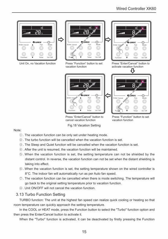
3.12 Vacation SettingVacation function: It’s used to keep the indoor ambient temperature and activate fast heating.Under heating mode, press “Function” button to select Vacation function with “Vacation” icon
flashing. Press “Enter/Cancel” button to activate Vacation function. When Vacation is on, press “Function” button to set function. Then press the “Enter/Cancel”
button to cancel Vacation function with no icon flashing. How to set vacation function is shown in the Fig.18:
Wired Controller XK60
15
Unit On, no Vacation function Press “Function” button to set vacation function
Press “Enter/Cancel” button to activate vacation function
Press “Function” button to set vacation function
Press “Enter/Cancel” button to cancel vacation function
Fig.18 Vacation SettingNote:
① .The vacation function can be only set under heating mode.② .The turbo function will be cancelled when the vacation function is set.③ .The Sleep and Quiet function will be cancelled when the vacation function is set. ④ .After the unit is resumed, the vacation function will be maintained.⑤ .When the vacation function is set, the setting temperature can not be shielded by the
distant control. In reverse, the vacation function can not be set when the distant shielding is taking into effect.
⑥ .When the vacation function is set, the setting temperature shown on the wired controller is 8°C. The indoor fan will automatically run as per Auto fan speed.
⑦ .The vacation function can be cancelled when there is mode switching. The temperature will go back to the original setting temperature prior to vacation function.
⑧ .Unit ON/OFF will not cancel the vacation function.
3.13 Turbo Function SettingTURBO function: The unit at the highest fan speed can realize quick cooling or heating so that
room temperature can quickly approach the setting temperature.In the COOL or HEAT mode, press the Function button to select the "Turbo" function option and
then press the Enter/Cancel button to activate it.When the "Turbo" function is activated, it can be deactivated by firstly pressing the Function

Wired Controller XK60
16
button to select the "Turbo" option and then pressing the Enter/Cancel button.Turbo function setting is as shown in Fig.19:
Unit On, no Turbo function Press “Function” button to set turbo function
Press “Enter/Cancel” button to activate turbo function
Press “Function” button to set turbo function
Press “Enter/Cancel” button to cancel turbo function
Fig.19 Turbo Function SettingNotes:
① .The Turbo function will not be deactivated due to power failure. In DRY, FAN and AUTO modes, the Turbo function is unavailable and the function symbol won’t be displayed.
② .The Turbo function will be automatically deactivated as the Quiet function is activated.③ .The FAN button can also be used to adjust Turbo function.
3.14 SAVE Function SettingEnergy Saving Function: Energy saving can make the air conditioner runs in a smaller
temperature range by setting lower limited value of setting temperature in the COOL or DRY mode and upper limited value in the HEAT mode.
(1). Energy Saving Setting for CoolingWhen the unit runs under the COOL or DRY mode, press the Function button to select the
“SAVE” function option, with “SAVE” flashing, and then press ▲ or ▼ to adjust the lower limit, after that, press the Enter/Cancel button to activate this function.
(2). Energy Saving Setting for HeatingWhen the unit runs under the HEAT mode, press the Function button to select the “SAVE”
function option, with “SAVING” flashing, then press the Mode button to switch to the “SAVE” setting for the HEAT mode and then press ▲ or ▼ to adjust the upper limit, after that, press the Enter/

Wired Controller XK60
17
Cancel button to activate this function.The activated SAVE function can be deactivated by firstly pressing the “Function” button to
select the “SAVE” option and then pressing the “Enter/Cancel” button.The energy saving setting is as shown in the Fig.20:
Unit On, no Save function Press “Function” button to set energy-saving temperature for Cooling
adjust temperature
Press "Mode" button to set energy-saving temperature for Heating.
adjust temperaturePress “Enter/Cancel” button to activate save function
Fig.20 SAVE Function Setting
Notes:① . Under the Auto mode, when the “SAVE” function is activated, the unit will forcibly quit the
Auto mode and change to the current operation mode. Further, the “Sleep” function will be deactivated when the “SAVE” function is activated.
② .During the “SAVE” setting, if the Function button is pressed down or there is not any operation within 5s after the last button operation, the system will quit the “SAVE” setting with the current setting data not saved.
③ .The “SAVE” function setting will be memorized in case of power failure.④ .The lower limit for cooling is 16 °C and the upper limit for heating is 30°C.⑤ .During the “SAVE” setting, if the expected setting temperature is out of the limit, then the
limit temperature always prevail.
Wired Controller XK60
18
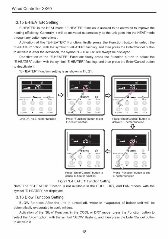
3.15 E-HEATER SettingE-HEATER: in the HEAT mode, “E-HEATER” function is allowed to be activated to improve the
heating efficiency. Generally, it will be activated automatically as the unit goes into the HEAT mode through any button operations .
Activation of the “E-HEATER” Function: firstly press the Function button to select the “E-HEATER” option, with the symbol “E-HEATER” flashing, and then press the Enter/Cancel button to activate it. After the activation, the symbol “E-HEATER” will always be displayed.
Deactivation of the “E-HEATER” Function: firstly press the Function button to select the “E-HEATER” option, with the symbol “E-HEATER” flashing, and then press the Enter/Cancel button to deactivate it.
“E-HEATER” Function setting is as shown in Fig.21:
Unit On, no E-heater function Press “Function” button to set E-heater function
Press “Enter/Cancel” button toactivate E-heater function
Press “Function” button to set E-heater function
Press “Enter/Cancel” button to cancel E-heater function
Fig.21 “E-HEATER” Function SettingNote: The “E-HEATER” function is not available in the COOL, DRY, and FAN modes, with the symbol “E-HEATER” not displayed.
3.16 Blow Function SettingBLOW function: After the unit is turned off, water in evaporator of indoor unit will be
automatically evaporated to avoid mildew.Activation of the “Blow” Function: in the COOL or DRY mode, press the Function button to
select the “Blow” option, with the symbol “BLOW” flashing, and then press the Enter/Cancel button to activate it.

Wired Controller XK60
19
Deactivation of the “Blow” Function: The activated “Blow” function can be deactivated by firstly pressing the Function button to select the “Blow” option and then pressing the Enter/Cancel button.
BLOW function setting is as shown in Fig.22:
Unit On, no Blow function Press “Function” button to set blow function
Press “Enter/Cancel” button to activate blow function
Press “Function” button to set blow function
Press “Enter/Cancel” button to cancel blow function
Fig.22 Blow Function SettingNotes:
① .When the “Blow” function is activated, if the unit is turned off through the On/Off button, the indoor fan will still run at low fan speed for another 10 minutes. When the “Blow” function is deactivated, the indoor fan will stop directly as the unit is turned off.
② .The “Blow” function is not available in the FAN and HEAT modes.
3.17 Filter SettingUnder On status, press “Function” button to set “Filter” function with “Filter” icon flashing. The
setting pollution level will be shown at the Timer area. Press “▲” and “▼” to adjust pollution level and press “Enter/Cancel” button to activate Filter function.
When the Filter function is set, press “Function” button to set with “Filter” icon flashing. Press “▲” and “▼” to adjust till “00” is shown on the timer area. Then press “Enter/Cancel” button to cancel the Filter function.
How to set Filter function is shown in the Fig.23:

Wired Controller XK60
20
Unit On, no Filter function Press “Function” button to set filter function the pollution level
Press “Enter/Cancel” button to activate filter function
Press “Function” button to set filter function“00” shown at the timer area
Press “Enter/Cancel” button to cancel filter function
Fig.23 Filter SettingWhile setting Filter, two numbers will be shown on the timer area. The first number represents
the pollution level. The second number shows the accumulated operating time of the indoor fan. There are four statuses in total:
① .No Filter function setting ( “00” shown at the timer area)② .When the filter reaches light-level pollution, “1” will be shown at the first place, When “0”
shows up at the second place, the accumulated operating hour reaches 5500h. Every increase of the number means another 500h is accumulated. When “9” shows up, it means the operating hour reaches 10000h.
③ .When the filter reaches middle-level pollution, “2” will be shown at the first place, When
Wired Controller XK60
21
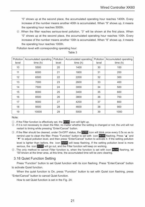
“0” shows up at the second place, the accumulated operating hour reaches 1400h. Every increase of the number means another 400h is accumulated. When “9” shows up, it means the operating hour reaches 5000h.
④ .When the filter reaches serious-level pollution, “3” will be shown at the first place, When “0” shows up at the second place, the accumulated operating hour reaches 100h. Every increase of the number means another 100h is accumulated. When “9” shows up, it means the operating hour reaches 1000h.
Pollution level with corresponding operating hour:Table 3
Pollution level
Accumulated operating time (h)
Pollution level
Accumulated operating time (h)
Pollution level
Accumulated operating time (h)
10 5500 20 1400 30 100
11 6000 21 1800 31 200
12 6500 22 2200 32 300
13 7000 23 2600 33 400
14 7500 24 3000 34 500
15 8000 25 3400 35 600
16 8500 26 3800 36 700
17 9000 27 4200 37 800
18 9500 28 4600 38 900
19 10000 29 5000 39 1000
Note:① .If the Filter function is effectively set, the icon will light up.② .If it is not necessary to clean the filter, no matter whether the setting is changed or not, the unit will not
restart to timing while pressing “Enter/Cancel” button. ③ .If the filter should be cleaned, under On/OFF status, the icon will blink once every 0.5s so as to
remind user to clean the filter. Press “Function” button to set with icon flashing. Press “▲” and “▼” to adjust pollution level, and then press “Enter/Cancel” button to activate it. If the setting pollution level is lighter than before, the icon will keep flashing. If the setting pollution level is more serious, the icon will go out, and the Filter function will keep on working.
④ .The only method to cancel Filter function is, when the function is set with icon flashing, let “00”shown at the timer area, at this time, the accumulated time will be zero clearing.
3.18 Quiet Function Setting Press “Function” button to set Quiet function with its icon flashing. Press “Enter/Cancel” button
to activate Quiet function.When the quiet function is On, press “Function” button to set with Quiet icon flashing, press
“Enter/Cancel” button to cancel Quiet function. How to set Quiet function is set in the Fig. 24:

Wired Controller XK60
22
Unit On, no Quiet function Press “Function” button to set quiet function
Press “Enter/Cancel” button to activate quiet function
Press “Function” button to set quiet function
Press “Enter/Cancel” button to cancel quiet function
Fig.24 Quiet function settingNotes:
① ."QUIET" function is unavailable in Fan or Dry mode. Owing to power failure, the "Quiet" function is defaulted to be deactivated.
② .If quite function is set, turbo function will be canceled.
3.19 Ultra-Dry Setting Under Dry mode, when the setting temperature is 16°C, press “▼” button twice and the setting
temperature will be changed to 12°C, at this time, the unit enters the Ultra-Dry function. When the Ultra-Dry function is activated, it can be cancelled by pressing “▲” button or pressing
“Mode” button to switch mode.
3.20 Other Functions
3.20.1 Lock FunctionUnder the ON state of the unit without any malfunction or under the OFF state of the unit, press
▲ and ▼buttons at the same time for 5s till the wired controller enters the lock state. In this case,
LCD displays . After that, repress these two buttons at the same time for 5s to quit the lock state.
Under the lock state, no response will be given to the other button operation.

Wired Controller XK60
23
3.20.2 Memory FunctionMemory switchover: Under the OFF state of the unit, press the Mode and ▲ buttons at the
same time for 5s to switch memory modes. When setting the memory mode, “MEMORY” will be displayed. If this function is deactivated, the unit will go to the OFF state after power recovery.
Memory recovery: If the memory function is On, the wired controller after power failure will resume its original running state upon power recovery. Note: It will take about 5 seconds to save data. Therefore, please do not cut down the power at this time, or data will fail to be saved.
3.20.3 Selection of Centigrade and FahrenheitUnder the OFF state of the unit, press the Mode and ▼ buttons at the same time for 5s,
Centigrade and Fahrenheit scales will be switched alternately.
3.20.4 Ambient Temperature Enquiry Under On/Off status, press “Confirm” button for 5s, it will enter Enquiry interface. At this time,
what shows on the timer area is the ambient temperature type: 01 or 02 and the temperature will be shown. “01” means the outdoor ambient temperature and “02” represents the indoor ambient temperature. Press “Mode” button to switch between those two types. Press any other button except Mode button or receive the signal from the remote controller will quit from the Enquiry function. If there is no operation in 20s, the unit will quit from this function automatically. Note:
① . If the unit is not connected with the ambient temperature sensor, after 12h electrification, the display of the ambient temperature sensor will be shielded.
② .If the outdoor temperature sensor has error, after 12h electrification, the display of the ambient temperature sensor will be shielded.
3.20.5 Indoor fan shutdown mode settingUnder unit OFF status, simultaneously press “Function” and “Timer” button for 5s, the wired
controller will enter parameter setting interface. Press “Mode” button to set till “05” is shown on the temperature displayed area. Then the unit will enter the indoor fan shutdown mode.
Two options are available for the indoor fan shutdown mode:Mode 1: When the temperature reaches certain value, the indoor fan will not be shut down
at any mode except heating mode. After the unit is shut down, for the duct type unit and the floor ceiling type unit, the indoor fan will blow the extra heat for 60s and then stop running. For the cassette type unit, its indoor fan will operate at low fan speed and blow the extra heat for 60s only when error happens to it.
Mode 2: No matter the unit is under which mode, the indoor fan will keep running for 10s after the temperature reaches certain value, then it will stop.
Press “▲” or “▼” button to adjust the mode. Under Mode 1/2, “00”/ “01” will show up in the timer area. Then press “Enter/Cancel” button to save the settings. The setting procedures are shown as Fig.25:

Wired Controller XK60
24
Unit off Simultaneously press “Function” and “Timer” button for 5s, the wired controller will enter parameter setting interface.
Press “Mode” button to set till “05” is shown on the temperature displayed area. Then the unit willenter the indoor fan shutdown mode.
Press “Enter/Cancel” button to save the settings and quit from the interface.
Fig.25 Indoor fan shutdown mode settingNote: In the parameter setting interface, only when “05” shown on it, the indoor fan shutdown mode can be set. Other parameters are not allowed to be modified and our company is not responsible for the unit damage or property loss due to parameter changed by customers.
4 Installation of the Wired Controller
4.1 Standard Parts
No. Description Quantity
1 Base Box 1
2 Soleplate 1
3 Screw M4×25 2
4 Front Panel 1
Table 4 Standard Parts
Fig.26 Standard Parts of the Wired Controller

Wired Controller XK60
25
4.2 Installation Location and Installation Requirements (1). Do not install the wired controller in the damp place or under direct sunlight.(2). Do not install the wired controller close to the hi-temperature object or place where the
wired controller is likely to suffer water spray.(3). Do not install the wired controller directly opposite to the window so as to avoid improper
operation caused by the interference of the neighbor’s same model wired controller. (4). Please cut off the power supply of wires embedded in the wall. No operation is allowed with
electricity. (5). To avoid abnormal operation caused by electromagnetic interference or other causes,
please take notice of the following statements during wiring. ① .Be sure the communication line is wired into the correct port, otherwise it would result in
communication fault.② .The communication line (wired controller) and power line must be separated with the
minimal distance of 20cm, otherwise it would result in communication fault.③ .Suppose that the air conditioner is installed where likely to suffer electromagnetic
interference, the communication line of the wired controller must be shielded twisted pair.
4.3 How to Install the Wired ControllerFirst of all, the selection and connecting method of the communication line is shown as follows:(1). Select appropriate communication line of the wired controller: 2-core signal line (wire
size≥0.75mm2, length<30m, recommended length: 8m).(2). After the indoor unit is de-energized, fix the communication line on the indoor terminal
board by screws.Then, the specific installation steps is shown in the Fig.27:
Fig.27 Installation of the Wired Controller

Wired Controller XK60
26
Brief instructions:① .Pull out the 2-core signal line from the mounting hole and pass this line through the round
hole located at the bottom of the wired controller. ② .Use M4×25 screws to fix the soleplate of the wired controller on the wall.
③ .Fix the signal line on the copper tabs X1 and X2. Make sure the line is tightly fixed and with no short-circuit potential.
④ .Set the panel and the bottom together by clasps.
4.4 How to Remove the Wired Controller The wired controller can be easily removed as shown in Fig.28
Fig.28 Removal of the Wired Controller
5 Error DisplayWhen error happens to the unit, the error code will be shown on the wired controller. When
multiple errors simultaneously happen, the error codes will circularly show up.When error occurs, please immediately shut down the unit and contact professional personnel.As shown in the Fig.29 means the high pressure protection.
Fig.29

Wired Controller XK60
27
Error codes and their meanings:Table 5
Number Error code Error
1 E1 Compressor high pressure protection
2 E2 Indoor anti-freeze protection
3 E3 Compressor low pressure protection, refrigerant lack protection and
refrigerant colleting mode
4 E4 Compressor high discharge temperature protection
5 E6 Communication error
6 E8 Indoor fan motor error
7 E9 Full water protection
8 F0 Indoor ambient temperature sensor error
9 F1 Evaporator temperature sensor error
10 F2 Condenser temperature sensor error
11 F3 Outdoor ambient temperature sensor error
12 F4 Discharge temperature sensor error
13 F5 Temperature sensor error of wired controller
14 C5 Capacity code error
15 EE Outdoor memory chip error
16 PF Electric box sensor error
17 H3 Compressor overload protection
18 H4 Overloading
19 H5 IPM protection
20 H6 DC fan motor error
21 H7 Drive desynchronizing protection
22 Hc Pfc protection
23 L1 Humidity sensor error
24 Lc Activation failure
25 Ld Compressor phase sequence protection
26 LF Power protection
27 Lp Indoor and outdoor mismatch
28 U7 4-way valve direction changing protection
29 P0 Drive reset protection
30 P5 Over-current protection
31 P6 Communication error between main control and drive
32 P7 Drive module sensor error

Wired Controller XK60
28
33 P8 Drive module over temperature protection
34 P9 Zero passage protection
35 PA AC current protection
36 Pc Drive current error
37 Pd Sensor connecting protection
38 PE Temperature drift protection
39 PL Bus low voltage protection
40 PH Bus high voltage protection
41 PU Charge loop error
42 PP Input voltage abnormality
43 ee Drive memory chip error

GREE ELECTRIC APPLIANCES, INC. OF ZHUHAI
Add: West Jinji Rd, Qianshan, Zhuhai, Guangdong, China, 519070Tel: (+86-756) 8522218 Fax: (+86-756) 8669426E-mail: [email protected] www.gree.com
Top Related