


Languages
Pages
Legal


System 1: GU supporting consoles and GU retaining angles
System 2: GU frame for projecting installation
Edition 01/2016
WINDOW TECHNOLOGY – ORDER CATALOGUE
Construction Accessories – Fastening Technology
Approved systems for projecting installation

Fastening technology І Projecting installation
2 GU І WP00014-04-0-1 І 01/2016
We create benefi ts for you
Professional installation of window elements
The energy balance of properties improves signifi cantly when
they are covered in a warm insulating layer. However, insulation
not only changes the heat balance of a building, but also its
structure: suddenly, the installation levels of windows and
balcony-doors are no longer in masonry, but in the area of the
insulation material. This cannot carry and transfer the loads.
Wit
h k
ind
pe
rmis
sio
n o
f A
rnd
t F
en
ste
rte
chn
ik G
mb
H &
Co
. KG
Only a projecting installation with elements suitable for it solves
the problem reliably: The construction carries the forces and
transfers them into the masonry, so that the reveal is not loaded
impermissibly due to tension or compression. Installation systems
from the GU Group perform this demanding task particularly
well. We have developed two systems for the projecting installa-
tion that are suitable for all profi le depths and that can be used
optimally with windows and balcony-doors made of PVC, timber,
timber/aluminium, and aluminium profi les.

3GU І WP00014-04-0-1 І 01/2016
Approved systems for projecting installationTable of contents
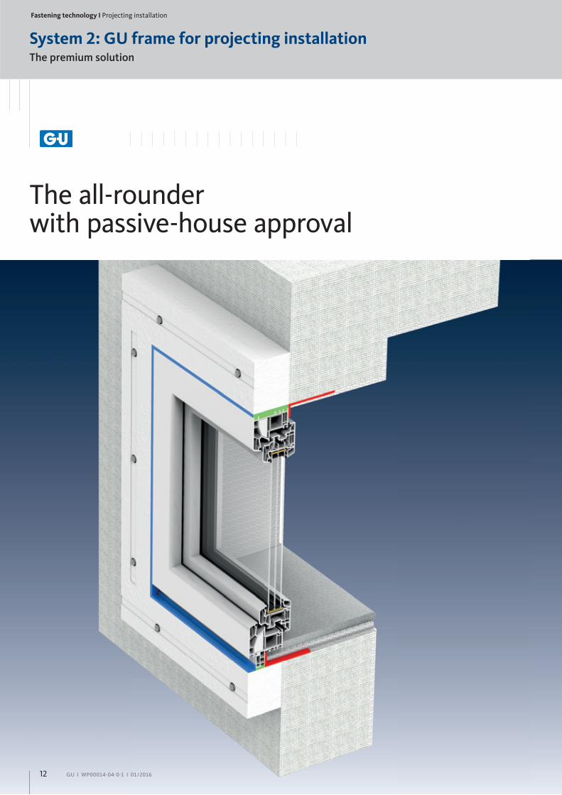
The premium solution
System 2: GU frame for projecting installation
The GU frame for projecting installation and its components is
our second system for a projecting installation. With the passive
house certifi ed door frame, structural elements can be mounted
in the insulation plane without thermal bridges occurring. Even
the installation of large and heavy windows or balcony-doors is
possible with our frame for projecting installation, because it is
tested for a load absorption of up to 579 kg. The door frame is
also approved for use as burglary protection in accordance with
EN 1627 and RC 2 and it has high performance in sound insulation
– these are strengths that are increasingly gaining importance.
As a genuine all-rounder, the GU frame for projecting installation
proves itself, for example, when used in double-layer clinker
facades: here it satisfi es the demands for load absorption, thermal
protection, windproofness and sound insulation with maximum
effi ciency.
The standard solution
System 1: GU supporting consoles and GU retaining angles
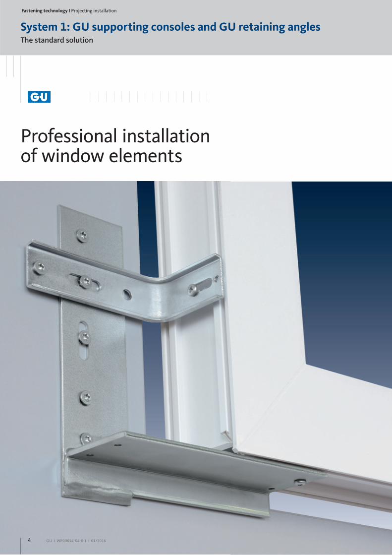
The fi rst system has been tested for safe transfer of loads by
ift Rosenheim, as well as for heavy structural elements, and
consists of the GU supporting consoles and GU retaining angles:
They give windows and balcony-doors stability up to 250 kg.
And because security is a top priority, the system has also been
tested according to EN 1627 for their reliability in terms of
burglar protection in resistance classes up to RC2. When it comes
to installation, our innovative consoles off er the advantages of
simple fi xing to vertical masonry, variable fi xing options as well as
their outstanding connection to the composite system of thermal
insulation.
System 2: GU frame for projecting installation
Advantages at a glance 12 – 13
Components
GU frame for projecting installation 14 – 15
GU anchor for projecting installation 16 – 17
GU 1K installation adhesive 18 – 21
Processing information 22 – 23
Test certifi cates 24 – 25
System 1: GU supporting consoles and GU retaining angles
Advantages at a glance 4 – 5
Components
GU supporting consoles 6 – 8
GU retaining angle 9
Processing information 10
Test certifi cates 11
Table of contents
Fastening technology І Projecting installation
System 1: GU supporting consoles and GU retaining angles
4 GU І WP00014-04-0-1 І 01/2016
Professional installation of window elements
The standard solution

5GU І WP00014-04-0-1 І 01/2016
Advantages at a glance
Optimum connection for exterior
insulation finishing system (EIFS)
High load-bearing capacity up to 250 kg
(ift-tested)
System tested for burglar protection
up to RC 2 (according to EN 1627)
Straightforward installation in masonry
with range of fixing options
All window installation fixing points
as prescribed by the recognized rules
of engineering can be achieved
Installation not subject to tension and
compression in the area of the reveal
Suitable for all profile depths as well as frame
materials made of timber, PVC and aluminium
Fastening technology І Projecting installation
6 GU І WP00014-04-0-1 І 01/2016
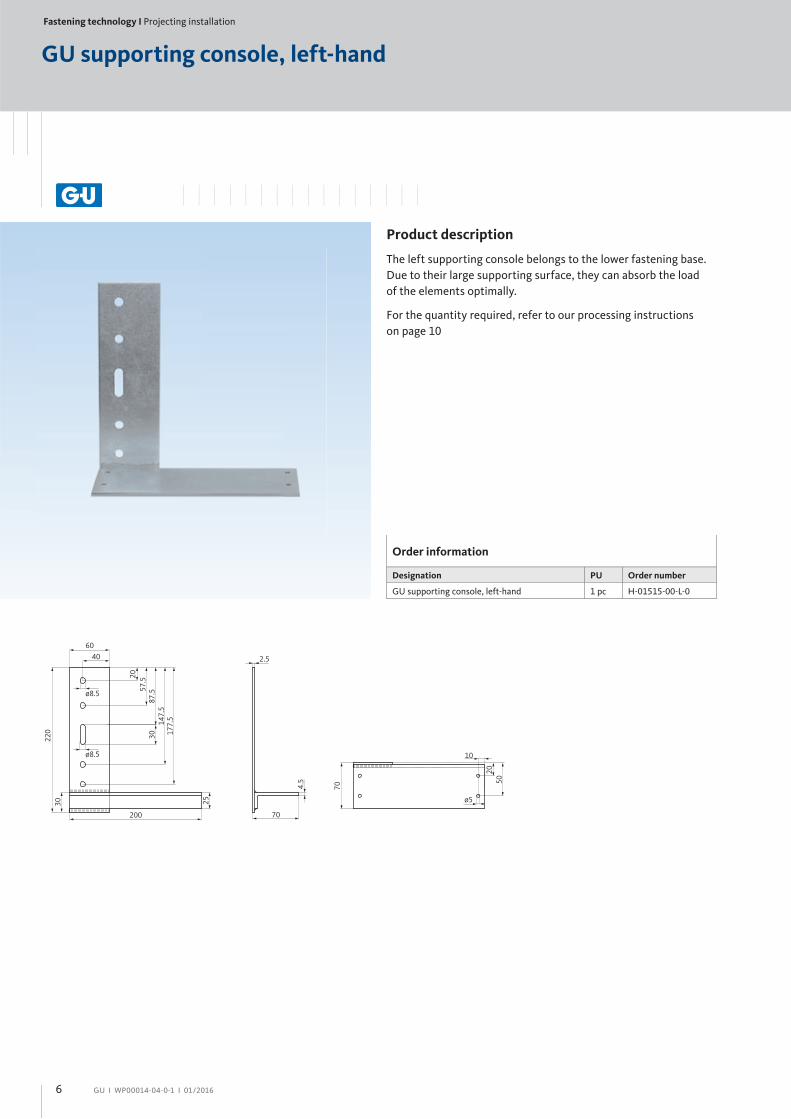
GU supporting console, left-hand
Order information
Designation PU Order number
GU supporting console, left-hand 1 pc H-01515-00-L-0
6040
ø8.5
ø8.5
200
2.5
70
ø5
10
2050
704.5
220
30
2057
.587
.514
7.5
177.5
30
25
Product description
The left supporting console belongs to the lower fastening base.
Due to their large supporting surface, they can absorb the load
of the elements optimally.
For the quantity required, refer to our processing instructions
on page 10

7GU І WP00014-04-0-1 І 01/2016
Order information
Designation PU Order number
GU supporting console, right-hand 1 pc H-01515-00-R-0
Product description
The right supporting console belongs to the lower fastening base.
Due to their large supporting surface, they can absorb the load
of the elements optimally.
For the quantity required, refer to our processing instructions
on page 10
6040
ø8.5
ø8.5
200
2.5
70
10
70
5020
ø5
4.5
220
3025
2057.5
87.5
30147.5
177.5
GU supporting console, right-hand
Fastening technology І Projecting installation
8 GU І WP00014-04-0-1 І 01/2016
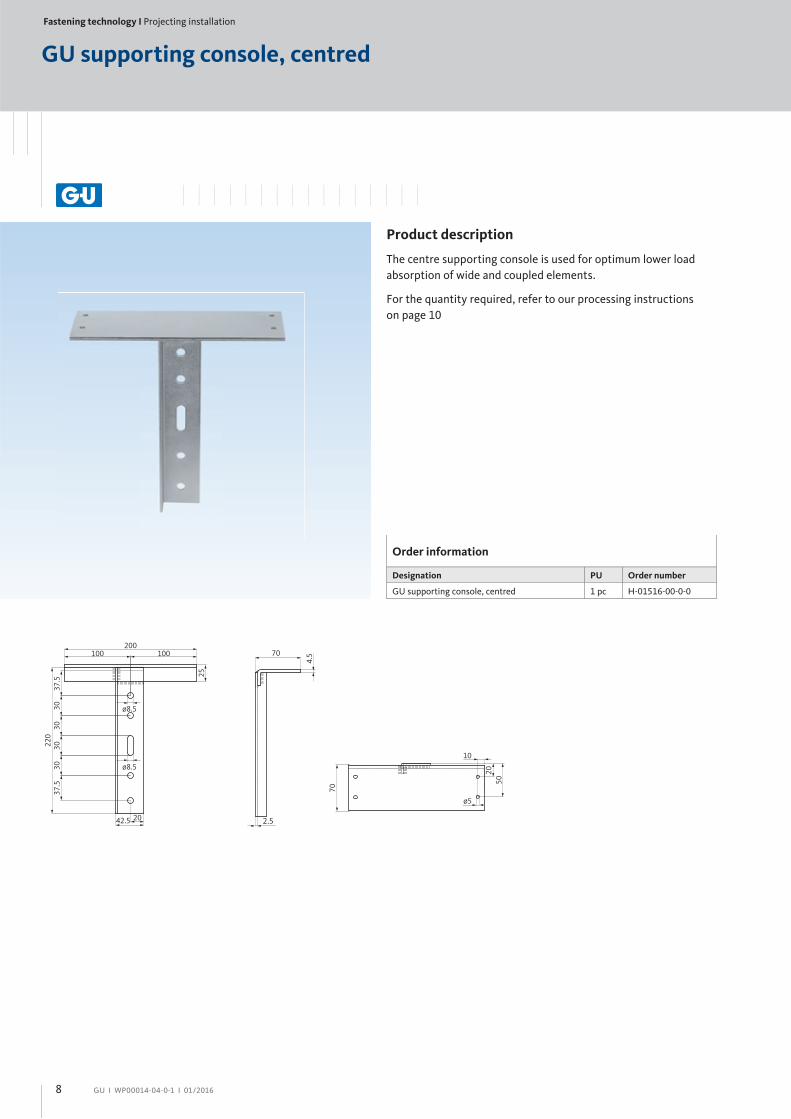
Order information
Designation PU Order number
GU supporting console, centred 1 pc H-01516-00-0-0
70200
100 100
ø8.5
ø8.5
2042.5
25
37.5
37.5
3030
3030
220
4.5
70
5020
10
ø5
GU supporting console, centred
Product description
The centre supporting console is used for optimum lower load
absorption of wide and coupled elements.
For the quantity required, refer to our processing instructions
on page 10
9GU І WP00014-04-0-1 І 01/2016
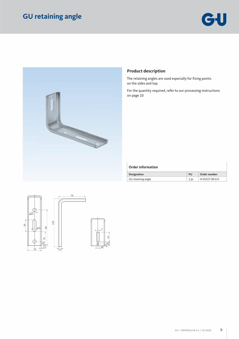
Order information
Designation PU Order number
GU retaining angle 1 pc H-01517-00-0-0
70
ø8.5
8.5
2.535 7.5
ø5
7
25105
125
30
9035
10
GU retaining angle
Product description
The retaining angles are used especially for fi xing points
on the sides and top.
For the quantity required, refer to our processing instructions
on page 10

Fastening technology І Projecting installation
10 GU І WP00014-04-0-1 І 01/2016
Processing information
The GU supporting consoles on the left and right and, where
appropriate, the GU supporting console at the centre are aligned
and fi xed to the masonry in advance. The window or balcony-door
frame is next, which is already prepared with the interior window
sealing sheet. In addition to the GU supporting consoles, it is
fi xed to the GU retaining angles on the masonry. The oblong holes
in the supporting consoles and retaining angles allow for quick
and easy adjustment to the masonry. The GU retaining angles are
critical for optimum installation of the component, because they
absorb dead loads, live loads and wind loads.
In the next step, the interior window sealing sheet is connected
or bonded to the masonry.
Maximum 150 mm from the element corner
The maximum spacing* between retaining
angles:
For PVC profi les ≤ 700 mm
For timber or
aluminium profi les ≤ 800 mm
* = Spacing of the fi xing points and
the number of GU retaining angles
must be matched to the active forces
and live loads (for example, dead
weight, additional load, vertical
and horizontal imposed load and
wind load) acting on the window
or balcony-door.
Number of required GU support consoles
and GU retaining angles
In principle, a right and a left GU supporting console should
be used for window elements and only fi xed with suitable screws
and dowels. The installation material must be aligned to the
surrounding wall system and to the edge distance.
The correct fi xing points and the number of fasteners are
important when installing windows and balcony-doors. The fi rst
fi xing point should not exceed 100 to 150 mm from the frame
inside corner. The distance between retaining angles may be max.
800 mm with timber or aluminium profi les and max. 700 mm with
PVC profi les. The individual distance to be chosen and thus the
required number of GU retaining angles is calculated from the
size of the window element to be fi tted and from the dead loads,
live loads and wind loads acting on it.
GU supporting consoles and GU retaining angles

11GU І WP00014-04-0-1 І 01/2016
Proven system solution from Gretsch-Unitas
Component testing for load-bearing capacity RC 2 approval in accordance with EN 1627
GU supporting consoles and GU retaining angles
Fastening technology І Projecting installation
System 2: GU frame for projecting installation
12 GU І WP00014-04-0-1 І 01/2016
The premium solution
The all-rounder with passive-house approval
13GU І WP00014-04-0-1 І 01/2016
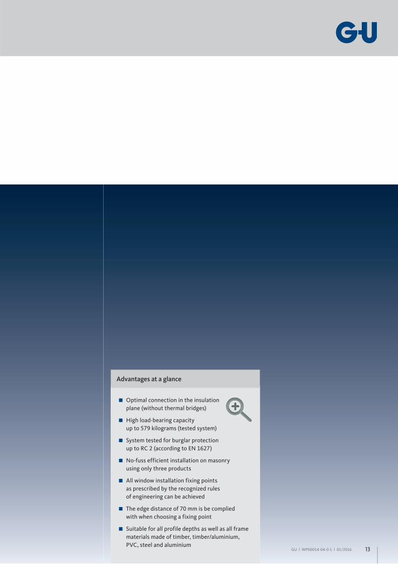
Advantages at a glance
Optimal connection in the insulation
plane (without thermal bridges)
High load-bearing capacity
up to 579 kilograms (tested system)
System tested for burglar protection
up to RC 2 (according to EN 1627)
No-fuss efficient installation on masonry
using only three products
All window installation fixing points
as prescribed by the recognized rules
of engineering can be achieved
The edge distance of 70 mm is be complied
with when choosing a fixing point
Suitable for all profile depths as well as all frame
materials made of timber, timber/aluminium,
PVC, steel and aluminium
Fastening technology І Projecting installation
14 GU І WP00014-04-0-1 І 01/2016
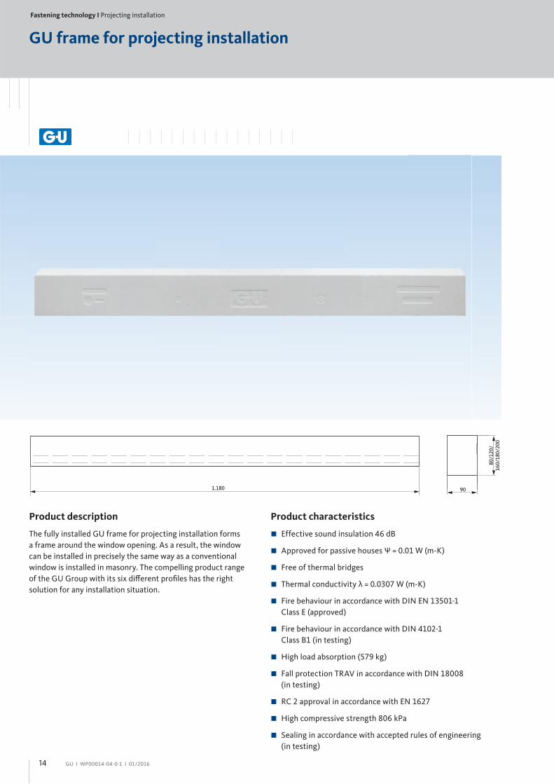
GU frame for projecting installation
Product description
The fully installed GU frame for projecting installation forms
a frame around the window opening. As a result, the window
can be installed in precisely the same way as a conventional
window is installed in masonry. The compelling product range
of the GU Group with its six diff erent profi les has the right
solution for any installation situation.
Product characteristics
Effective sound insulation 46 dB
Approved for passive houses Ψ = 0.01 W (m-K)
Free of thermal bridges
Thermal conductivity λ = 0.0307 W (m-K)
Fire behaviour in accordance with DIN EN 13501-1
Class E (approved)
Fire behaviour in accordance with DIN 4102-1
Class B1 (in testing)
High load absorption (579 kg)
Fall protection TRAV in accordance with DIN 18008
(in testing)
RC 2 approval in accordance with EN 1627
High compressive strength 806 kPa
Sealing in accordance with accepted rules of engineering
(in testing)
1.180 9080
/120
/16
0/18
0/20
0

15GU І WP00014-04-0-1 І 01/2016
Order information
Designation Dimensions Colour PU PU/Pallet Order number
GU frame for projecting installation
90 x 80 x 1180 mm white 30 pcs 60 pcs H-01573-08-0-7
90 x 120 x 1180 mm white 24 pcs 48 pcs H-01573-12-0-7
90 x 160 x 1180 mm white 16 pcs 32 pcs H-01573-16-0-7
90 x 180 x 1180 mm white 14 pcs 28 pcs H-01573-18-0-7
90 x 200 x 1180 mm white 12 pcs 24 pcs H-01573-20-0-7
min. 60 mm*
Note: for anti-burglary elements with resistance class RC 2 min. 70 mm
Fastening the frame profi le to the GU frame for projecting installation
Fastening technology І Projecting installation
16 GU І WP00014-04-0-1 І 01/2016
GU anchor for projecting installation
Product characteristics
Approved for all common building materials
Reliable hold even in problem building materials
thanks to optimised expansion part
Secure fit thanks to radial expansion
Cr (VI)-free surface of the dowel screw
Twice the anti-twist protection for a secure installation
Base materials
Approved: concrete, solid bricks, lime sand solid bricks,
lightweight concrete solid bricks, vertical coring bricks, vertical
coring lightweight bricks, lime sand ventilating bricks, lightweight
concrete hollow blocks, porous lightweight concrete.
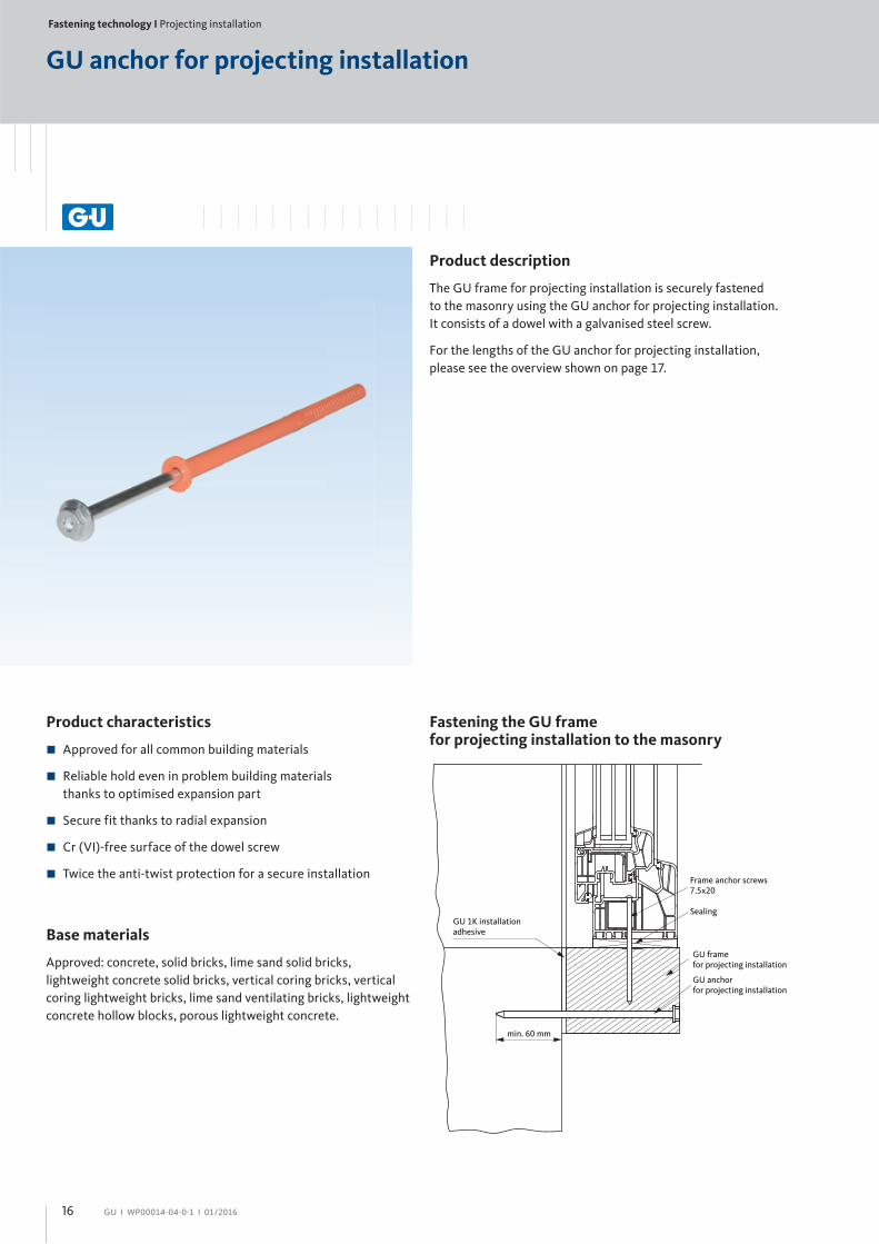
Product description
The GU frame for projecting installation is securely fastened
to the masonry using the GU anchor for projecting installation.
It consists of a dowel with a galvanised steel screw.
For the lengths of the GU anchor for projecting installation,
please see the overview shown on page 17.
Fastening the GU frame for projecting installation to the masonry
Sealing
Frame anchor screws 7.5x20
GU anchorfor projecting installation
GU framefor projecting installation
GU 1K installationadhesive
min. 60 mm

17GU І WP00014-04-0-1 І 01/2016
Technical data and requirements
Characteristic values
Borehole depth in concrete h1.1 ≥ 80 mm
Eff ective anchor depth hnom ≥ 70 mm
Borehole diameter d0 10 mm
Drive SW13/T40
Characteristic loads
Tensile loads NRk,p
Temperature range 30 °C / 50 °C 4.50 kN
Temperature range 50 °C / 80 °C 4.00 kN
Building bricks Mz 20-1.8, NF 4.00 kN
Lime sand solid bricks KS 36, NF 4.50 kN
Lime sand solid bricks KS 20, 8 DF 4.50 kN
Lightweight concrete solid bricks, V6, 2 DF 2.00 kN
Porous lightweight concrete 2.00 kN
Vertical coring bricks HLz 12-0,9, NF 2.00 kN
Lime sand ventilating bricks KSL 12, 4 DF 2.50 kN
Lightweight concrete hollow block Hbl 10, 12 DF 1.20 kN
Lateral loads VRk,s
Dowel with steel screw 9.35 kN
Dowel with stainless steel screws A4 10.91 kN
Bending moment MRk,s
Dowel with steel screw 17.67 Nm
Dowel with stainless steel screws A4 20.62 Nm
Fixing instructions
GU frame for projecting installationGU anchor for projecting installation
10 x 160 mm 10 x 180 mm 10 x 220 mm 10 x 240 mm 10 x 260 mm
90 x 80 mm
90 x 120 mm
90 x 160 mm
90 x 180 mm
90 x 200 mm
Order information
Designation Dimensions PU Order number
GU anchor for projecting installation
10 x 160 mm 100 pcs H-01624-16-0-1
10 x 180 mm 100 pcs H-01624-18-0-1
10 x 220 mm 100 pcs H-01624-22-0-1
10 x 240 mm 100 pcs H-01624-24-0-1
10 x 260 mm 100 pcs H-01624-26-0-1
Fastening technology І Projecting installation
18 GU І WP00014-04-0-1 І 01/2016
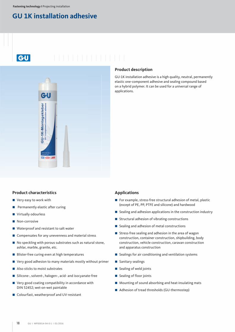
GU 1K installation adhesive
Product description
GU-1K installation adhesive is a high quality, neutral, permanently
elastic one-component adhesive and sealing compound based
on a hybrid polymer. It can be used for a universal range of
applications.
Product characteristics
Very easy to work with
Permanently elastic after curing
Virtually odourless
Non-corrosive
Waterproof and resistant to salt water
Compensates for any unevenness and material stress
No speckling with porous substrates such as natural stone,
ashlar, marble, granite, etc.
Blister-free curing even at high temperatures
Very good adhesion to many materials mostly without primer
Also sticks to moist substrates
Silicone-, solvent-, halogen-, acid- and isocyanate-free
Very good coating compatibility in accordance with
DIN 52452; wet-on-wet paintable
Colourfast, weatherproof and UV-resistant
Applications
For example, stress-free structural adhesion of metal, plastic
(except of PE, PP, PTFE and silicone) and hardwood
Sealing and adhesion applications in the construction industry
Structural adhesion of vibrating constructions
Sealing and adhesion of metal constructions
Stress-free sealing and adhesion in the area of wagon
construction, container construction, shipbuilding, body
construction, vehicle construction, caravan construction
and apparatus construction
Sealings for air conditioning and ventilation systems
Sanitary sealings
Sealing of weld joints
Sealing of floor joints
Mounting of sound absorbing and heat-insulating mats
Adhesion of tread thresholds (GU-thermostep)

19GU І WP00014-04-0-1 І 01/2016
Technical data and requirements
GU 1K installation adhesive Classifi cation and grading NF / ISO / DIN standard
Base 1 component hybrid polymer
Consistency Stable paste
Curing methodPolymerisation through air humidity at room temperature
Film formation time [1] approx. 10 minutes
Curing speed [1] 2 - 3 mm in the fi rst 24 hours
Shore A – hardness 40 ± 5 DIN 53505
Density 1.67 g/ml DIN 53479
Thermal stability -40 °C up to +90 °C
Recovery > 75 % ISO 7389-B
Max. permissible total deformation 20 % EN ISO 11600
Elastic modulus 100 % 0.75 N/mm2 EN ISO 8339
Tensile strength 1.8 N/mm2 DIN 53504
Combined tension and shear resistance [2] 0.9 N/mm2 DIN 53504
Percent elongation at failure 750 % DIN 53504
Volume change -3 up to -4 Vol. % EN ISO 10563
Building material class B2 (normally infl ammable) DIN 4102, part 4
[1] Measured according to standard atmosphere (EN ISO 291) at 23 °C / 50 % rel. hum. These values can vary due to environmental factors such as temperature, humidity and the nature of the substrate.[2] Substrate AlMgSi1, layer thickness 2 mm, feed rate 10 mm/minute.
Order information
Designation Packaging Contents Colour PU/Box Order number
GU 1K installation adhesiveCartridge 290 ml grey 12 pcs H-01175-00-0-0
Soft-pack 600 ml grey 20 pcs H-01175-60-0-0

Fastening technology І Projecting installation
20 GU І WP00014-04-0-1 І 01/2016
Substrates
The GU-1K installation adhesive cures excellently on a variety
of substrates and mostly without primer. These include metals
(AlCuMg1, AlMgSi1, brass, zinc, steel ST, 1403 electro-
galvanised and hot-dip-galvanised steel and other steels),
plastics (polystyrene, polycarbonate, PVC, ABS, polyamide,
PMMA and GRP – but not PE, PP, PTFE and silicone),
polystyrene, cork, enamel, concrete, glass, HPL and wood.
In general, care should be taken with plastics to ensure that
release agents used in manufacture or protective films used
for transport are removed before gluing, leaving no residue.
Otherwise, adhesion to the component deteriorates
considerably. Plastics containing plasticisers (e.g. soft PVC,
butyl rubber, EPDM and APTK) may exhibit incompatibilities
such as discolouration and loss of adhesion. Suitability for
use with the system should be tested in such cases.
Caution: PMMA and polycarbonate must be glued under
tension, or otherwise stress cracks will form. Preliminary
testing is strictly recommended for polycarbonate
Adhesion surfaces must always be suitable for coating, clean,
and free of dust and grease. Dry and clean substrates are
particularly suitable and produce the best bond values.
GU 1K installation adhesive also sticks to moist substrates,
and even underwater. Adhesion achieved in this way may,
however, be weaker than adhesion to dry and clean substrates
Pretreatment: porous substrates that are subject to relatively
high water loads should be pretreated with GU primer if
appropriate. For all smooth surfaces we also recommend
to improve the adhesion by using a GU primer.
GU 1K installation adhesive
Storage
Store in the unopened packaging in a cool (+5 °C to +25°C),
dry place. Seal opened containers well and use quickly
Processing
Application method
–GU manual or compressed-air gun
Processing temperature
–Ambient temperature: +0 °C (frost-free) to +40 °C
–Temperature of adhesive surface: +0 °C (frost-free) to +35 °C
Caution: Curing of the GU-1K installation adhesive occurs
from outside to inside as a result of air humidity at room
temperature and slows over time. At low temperatures
and/or low air humidity curing can be significantly slower!
Joint dimensions
Minimum width
–for gluing: 2 mm
–for sealing: 5 mm
Maximum width
–for gluing: 10 mm
–for sealing: 30 mm
Minimum depth
–for gluing: 2 mm
–for sealing: 5 mm
Recommended
–Joint width = 2 x joint depth (> 6 mm width)
–Joint width = 1 x joint depth (< 6 mm width)
Safety instructions
Observe standard workplace hygiene

21GU І WP00014-04-0-1 І 01/2016
Chemical resistance
Good: water, aliphetic solvents, dilute anorganic acids and
alkalis, oils and greases
Bad: aromatic solvents, concentrated acids and chlorinated
hydrocarbons
Note
The GU-1K installation adhesive is paintable.
Due to the variety of coating systems available on the market,
we recommend carrying out compatibility and adhesion tests
in advance. For example, in accordance with the relevant
standards such as DIN 18540, elastic sealing compounds
should not be coated completely, because otherwise cracks
can form in the non-elastic paint when tensions and move-
ments occur. The drying time of alkyd resin paints may also be
delayed. Any soap residue from the smoothing water should
be removed prior to coating, as this can impair the adhesion
of the coating. An adhesion and compatibility test for the
adhesive itself is advisable for the different substrates.

Fastening technology І Projecting installation
22 GU І WP00014-04-0-1 І 01/2016
Processing information
The GU frame for projecting installation is a powerful problem
solver for modern construction and energetic renovation.
Windows and balcony-doors can no longer be fi xed directly
through the frame to the masonry in the case of multiple-layer
outer walls that are formed by fi xing a exterior insulation fi nishing
system (EIFS). Conventional installation was done in the EIFS i.e.
in a nonstructural material.
Supporting structures are therefore essential for the fi xing frame
of structural elements. The GU frame for projecting installation
performs its function particularly well thanks to its impressive
features. It is very effi cient to work with and has been tested for
burglary protection to EN 1627 up to resistance class RC 2. In
addition, the rectangular cross-section of the frame provides
fl exibility: it can be installed in two positions, so that, for example,
the installation depth can vary between 90 and 120 millimetres.
Installation – step 1
During installation, the GU frame for projecting installation fi xed
under the component is fi rst cut to the length of the dimensions
of the window. The dimension here is calculated from the left
outer edge of the frame formed by the frame to the right outside
edge. The horizontal lower element is therefore measured along
the full length, and the upper frame is also measured in the same
way. The vertical frames are fi tted to the sides of the window
between these horizontal elements.
Installation – step 2
After cutting, the GU-1K installation adhesive is applied bead-
and serpentine-like to the frame for projecting installation and
then bonded to the surrounding masonry. The special processing
instructions of the products used and the surface treatment must
be observed.
Installation – step 3
Then the bonded GU frame for frame for projecting installation
is also fi xed to the GU anchor for projecting installation. At least
three anchors per frame must be installed and the positions on
the frame where they must be fi xed is described in the graphic on
the opposite side. The maximum distances from the outer edges
of the GU frame for projecting installation to the fi rst screw
connection is 150 millimetres with a maximum of 700 millimetres
between the fi xing points. Carrying out the screw connection
according to these specifi cations provides the necessary edge
spacing for fi xing stability on all sides.
Installation – step 4
The structural elements are installed perpendicularly and fl ush
with the GU frame for projecting installation. Fixing the lower
shims is not required for an exact plumbing of the frame.
Installation of the window is carried out with self-cutting frame
anchor screws (diameter 7.5 mm). When selecting the screw
length, it is essential to ensure that there is a minimum screw
depth of 60 millimetres in the GU frame for projecting
installation. In addition, the separate test certifi cate and the
corresponding installation instructions must be observed with
anti-burglary versions.
Installation – step 5
The sealing between the structural element and the GU frame
for projecting installation is made in the last step. GU gun foam,
GU outside window sealing tape, GU joint sealing tape,
GU sealing tape BG1 and other sealing products of the GU Group
are used here.
Note: During the entire installation process, the "Guidelines
for planning and executing the installation of windows and house
doors for new constructions and renovations" of the RAL-Güte-
gemeinschaft Fenster und Haustüren e.V. should be observed.
Installation examples
Suitable for all profi le depths and frame materials Especially suitable for use in double-layer clinker facades:
Here the GU frame for projecting installation satisfi es the demands for load absorption, thermal protection, windproofness and sound insulation with maximum effi ciency.
GU frame for projecting installation

23GU І WP00014-04-0-1 І 01/2016
Features and benefi ts of projecting installation at a glance
Positioning and installing the window in the insulation plane
without much effort
No risk of thermal bridges
Perfect for clinker facades: installation in the insulation plane,
systematic load absorption and precise sealing
GU frame for projecting installation can be used either-way
(for example, 90/120 mm)
Complete installation using only three products:
–GU frame for projecting installation
–GU anchor for projecting installation
–GU 1K installation adhesive
These three products together constitute an approved system
Airtight installation on the masonry using
GU-1K installation adhesive
Edge distance of 70 mm (indicated by a mark) is complied
with when choosing a fixing point
All mounting points for the GU frame for projecting
installation are complied with, even for PVC and timber/
aluminium profiles
Combinable with the GU supporting consoles and
GU retaining angles from system 1
Can be plastered and painted-over
GU frame for projecting installation can be drilled, screwed
and sawn, thus enabling quick and easy installation
Window is fitted in prefabricated frame without additional
drilling
GU anchor for projecting installation can be used with
all types of stone
max.
150 mm
max.
700 mm
max.
700 mm
max. 150
mm
ma
x.
70
0 m
m
ma
x.
15
0 m
m
ma
x.
70
0 m
m
ma
x.
15
0 m
m

Fastening technology І Projecting installation
24 GU І WP00014-04-0-1 І 01/2016
Component testing of sound insulation RC 2 approval in accordance with EN 1627
Component testing of suitability
for use in low-energy and passive houses
Component testing for load-bearing capacity
Proven system solution from Gretsch-UnitasGU frame for projecting installation

25GU І WP00014-04-0-1 І 01/2016
Testing the fi re behaviour of construction products
in accordance with EN ISO 11925-2: 2010
Classifi cation for fi re behaviour
in accordance with EN 13501-1: 2010
Component testing of thermal conductivity

Fastening technology І Projecting installation
26 GU І WP00014-04-0-1 І 01/2016
Exclusion of liability / Copyright notice / Image credits
Image credits
Page 2 With kind permission of Arndt Fenstertechnik GmbH & Co. KG
Exclusion of liability
The information provided in this publication consists of product
descriptions. This is general information based on our experience
and tests and therefore does not take any specifi c application into
account. No claims for compensation can be made on the basis of
the product descriptions.
Although we have made every attempt to ensure the information
provided here is accurate, it is non-binding. It should be adapted
to the respective construction projects, usage and specifi c on-site
demands.
The publication has been compiled to the best of our knowledge.
The Gretsch-Unitas Group accepts no liability for any errors.
The document is subject to modifi cations during the course of
technical developments.
The product images shown in the publication may diff er from
the actual product.
Copyright notice
© All illustrations and texts in this publication are protected by
copyright. Unless otherwise stated in the image credits, the rights
belong to the Gretsch-Unitas Group. Any use of copyright
protected materials without the consent of the holder of the
rights is prohibited.
Publisher
Gretsch-Unitas GmbH
Baubeschläge
Johann-Maus-Str. 3
71254 Ditzingen, Germany
Tel. + 49 (0) 71 56 3 01-0
Fax + 49 71 56 3 01-2 93
www.g-u.com
27GU І WP00014-04-0-1 І 01/2016

WP
00
01
4-0
4-0
-1
0
1/2
01
6
Pri
nte
d in
Ge
rman
y
www.g-u.com
BKS GmbH
Heidestr. 71
D-42549 Velbert
Tel. + 49 (0) 2051 201-0
Fax + 49 (0) 2051 201-9733
Gretsch-Unitas GmbH
Baubeschläge
Johann-Maus-Str. 3
D-71254 Ditzingen
Tel. + 49 (0) 7156 301-0
Fax + 49 (0) 7156 301-77980