


Languages
Pages
Legal


What Makes Boomerangs Come Back?
Ernie Esser
UCLA
1

Parts of a Boomerang
[Hawes,All About Boomerangs]
2
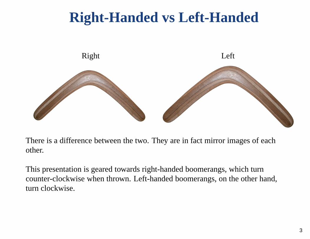
Right-Handed vs Left-Handed
Right Left
There is a difference between the two. They are in fact mirrorimages of eachother.
This presentation is geared towards right-handed boomerangs, which turncounter-clockwise when thrown. Left-handed boomerangs, on the other hand,turn clockwise.
3

Goals for the talk:
• Discuss the lift equation, why a boomerang generates lift and how theselift forces produce torque on a boomerang
• Explain gyroscopic precession and why torque on a boomerangmakes itturn
• Estimate the characteristic radius of a boomerang’s flight path• Explain a boomerang’s tendency to lay over as it flies• Comment on how to construct a boomerang• Discuss boomerang throwing and catching techniques
4

Aerodynamic Lift
An airfoil produces lift when the combined effects of its orientation (angle ofattack) and its shape cause oncoming air to be deflected downward.
Sketch of Streamlines
[Acheson,Elementary Fluid Dynamics]
Boomerang wing cross section Bevel on lifting arm
5
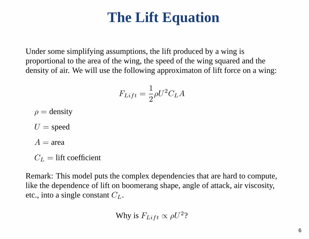
The Lift Equation
Under some simplifying assumptions, the lift produced by a wing isproportional to the area of the wing, the speed of the wing squared and thedensity of air. We will use the following approximaton of lift force on a wing:
FLift =1
2ρU2CLA
ρ = density
U = speed
A = area
CL = lift coefficient
Remark: This model puts the complex dependencies that are hard to compute,like the dependence of lift on boomerang shape, angle of attack, air viscosity,etc., into a single constantCL.
Why isFLift ∝ ρU2?
6

Intuition from Oversimplification
Downwash from a helicopter
Recall Newton’s Second Law: force= rate of change of momentum
where momentum= mass· velocity
mass of air deflected per unit time∝ ρU
change in deflected air’s vertical velocity∝ U
⇒ FLift ∝ ρU2
7
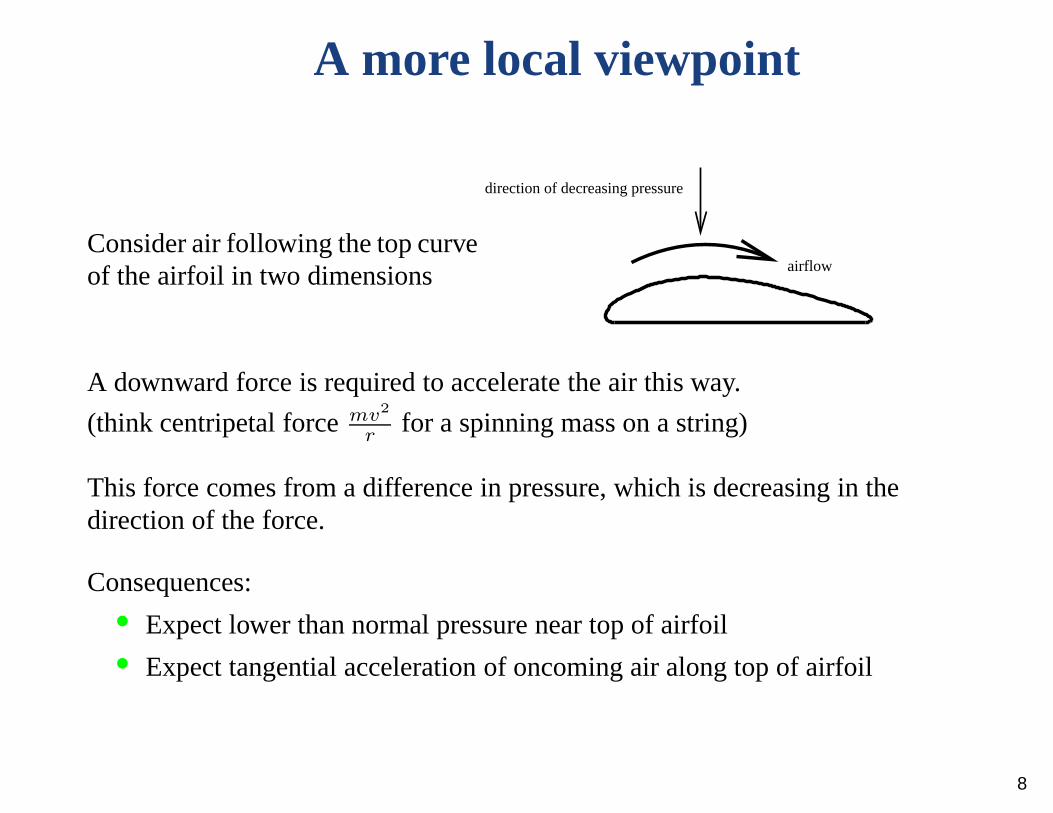
A more local viewpoint
Consider air following the top curveof the airfoil in two dimensions airflow
direction of decreasing pressure
A downward force is required to accelerate the air this way.
(think centripetal forcemv2
rfor a spinning mass on a string)
This force comes from a difference in pressure, which is decreasing in thedirection of the force.
Consequences:• Expect lower than normal pressure near top of airfoil• Expect tangential acceleration of oncoming air along top ofairfoil
8

Bernoulli’s Equation
PressureP and velocityu are related by Bernoulli’s equation
P +1
2ρ|u|2 = c (for some constantc)
Assuming: constant densityρ
zero viscosityµ (inviscid)
incompressible
steady flow (time independent)
irrotational (no vortices)
Comment: If the flow is rotational, the equation still holds but c can bedifferent on different streamlines.
To compute force on the airfoil, we can integrateP times the inward pointingnormaln along the boundary of the airfoil. Assumingu → αu whenU → αU , we again expect to haveFLift ∝ ρU2.
9
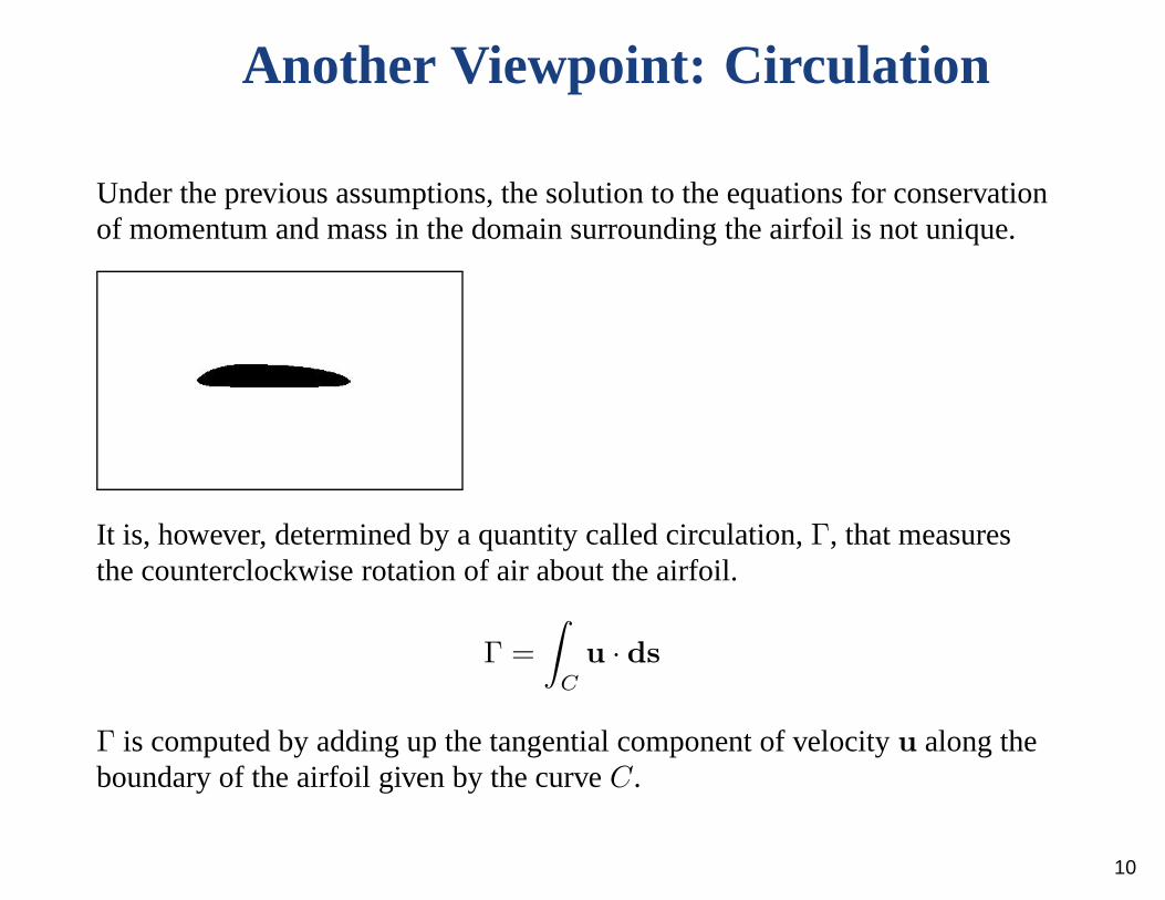
Another Viewpoint: Circulation
Under the previous assumptions, the solution to the equations for conservationof momentum and mass in the domain surrounding the airfoil isnot unique.
It is, however, determined by a quantity called circulation, Γ, that measuresthe counterclockwise rotation of air about the airfoil.
Γ =
∫C
u · ds
Γ is computed by adding up the tangential component of velocity u along theboundary of the airfoil given by the curveC.
10

Viscous Effects Determine Circulation
For an airfoil with a corner at the trailing edge, all solutions to the inviscidproblem have a singularity in the velocity there except for one. Adding eventhe tiniest amount of viscosity picks out the solution wherea stagnation pointis at the corner. (Kutta Condition)
Zero Circulation Negative Circulation
[Acheson,Elementary Fluid Dynamics]
Comments:• Equal transit time argument is false. Negative circulationimplies air
moving even faster above airfoil.• Need to include effect of viscosity to correctly model dynamics.
Conservation of angular momentum plus decreasing circulation requiresshedding of counterclockwise vortex.
11

Computing Lift and Drag
Assume uniform air speedU at infinity.FDrag is the force on the airfoil in the direction of the oncoming air, andFLift is perpendicular to the flow.
FLift = −ρUΓ
FDrag = 0
• Good approximation of lift on an airfoil when viscosity and angle ofattack are small
• Useless for computing drag because inviscid model doesn’t have anytangential forces on airfoil
Note: To incorporate tangential shear forces due to viscosity,
F =
∫C
(P − 2µD) · nds
whereD is the deformation matrix and depends on rates of change of velocityu. 12
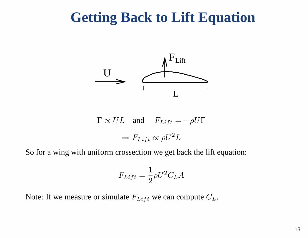
Getting Back to Lift Equation
L
U
FLift
Γ ∝ UL and FLift = −ρUΓ
⇒ FLift ∝ ρU2L
So for a wing with uniform crossection we get back the lift equation:
FLift =1
2ρU2CLA
Note: If we measure or simulateFLift we can computeCL.
13
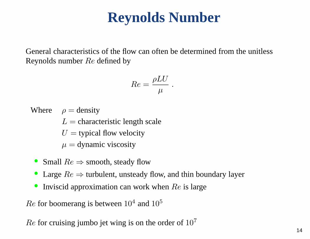
Reynolds Number
General characteristics of the flow can often be determined from the unitlessReynolds numberRe defined by
Re =ρLU
µ.
Where ρ = density
L = characteristic length scale
U = typical flow velocity
µ = dynamic viscosity
• SmallRe ⇒ smooth, steady flow• LargeRe ⇒ turbulent, unsteady flow, and thin boundary layer• Inviscid approximation can work whenRe is large
Re for boomerang is between104 and105
Re for cruising jumbo jet wing is on the order of107
14

2D Navier Stokes Simulation
The Navier Stokes equations for an incompressible fluid withconstant densityρ, constant viscosityµ, and no forcing terms are
ρ∂u
∂t+ ρ(u · ∇)u = −∇P + µ4u
∇ · u = 0
Simulate flow around2D cross section of boomerang arm usingsemi-Lagrangian finite element method.
Boundary Conditions: Parabolic inflow on left side
Neumann boundary condition on right side
Zero velocity (no slip) on top, bottom and airfoil surface
Initial Condition: Zero velocity
Note: Displayed results will be for a zoomed in region surrounding the airfoil
15
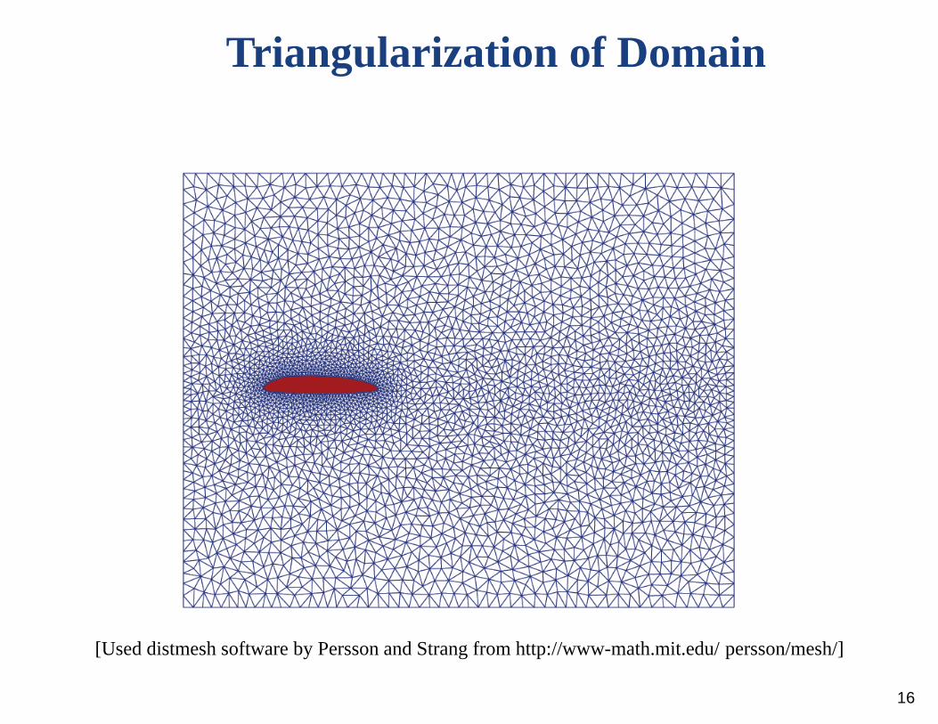
Triangularization of Domain
[Used distmesh software by Persson and Strang from http://www-math.mit.edu/ persson/mesh/]
16
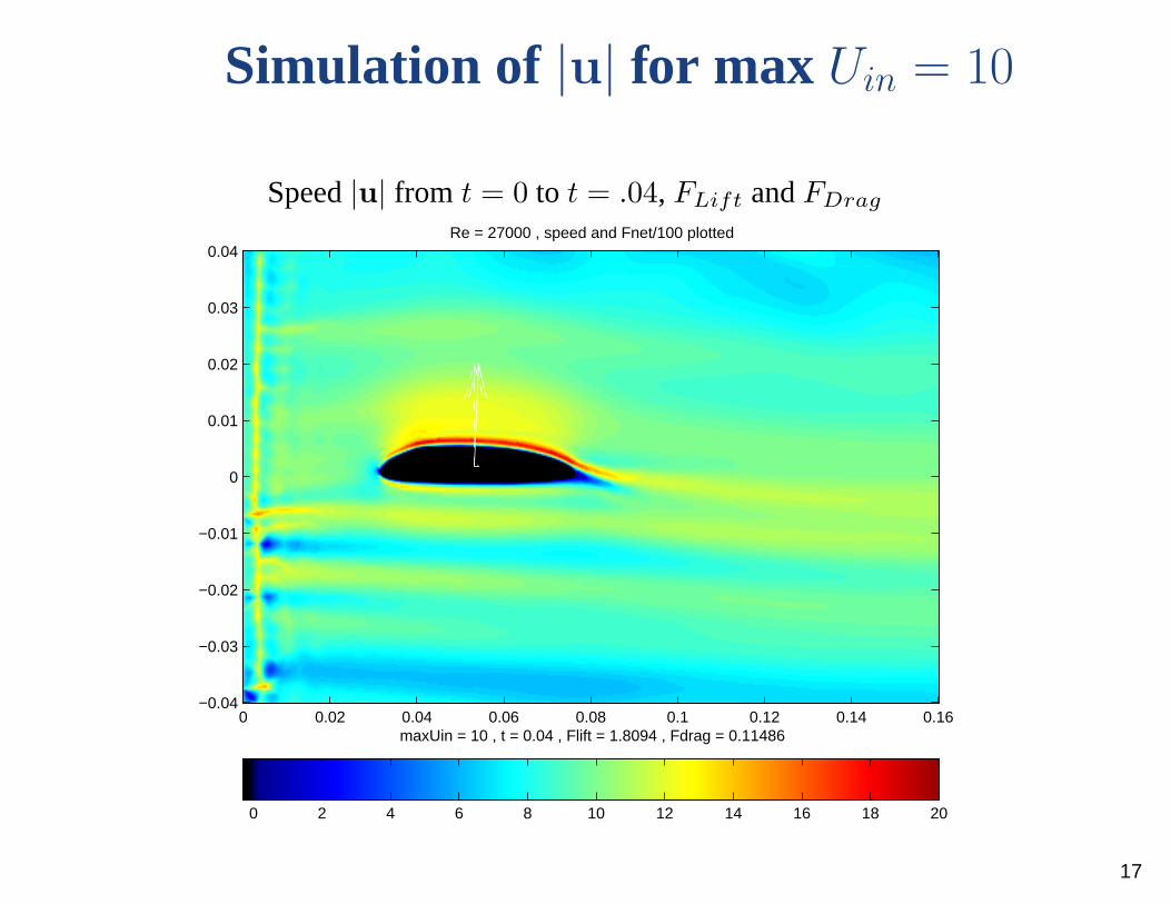
Simulation of |u| for max Uin = 10
Speed|u| from t = 0 to t = .04, FLift andFDrag
0 2 4 6 8 10 12 14 16 18 20
maxUin = 10 , t = 0.04 , Flift = 1.8094 , Fdrag = 0.11486
Re = 27000 , speed and Fnet/100 plotted
0 0.02 0.04 0.06 0.08 0.1 0.12 0.14 0.16−0.04
−0.03
−0.02
−0.01
0
0.01
0.02
0.03
0.04
17
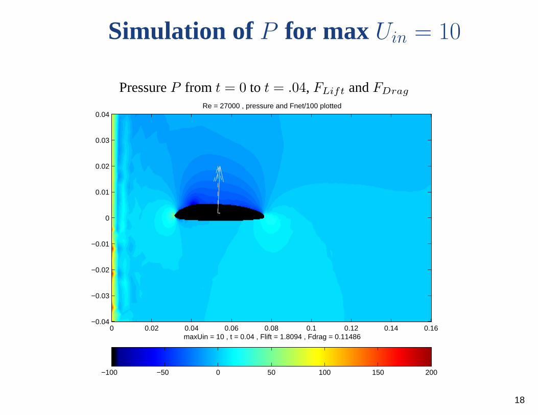
Simulation of P for max Uin = 10
PressureP from t = 0 to t = .04, FLift andFDrag
−100 −50 0 50 100 150 200
maxUin = 10 , t = 0.04 , Flift = 1.8094 , Fdrag = 0.11486
Re = 27000 , pressure and Fnet/100 plotted
0 0.02 0.04 0.06 0.08 0.1 0.12 0.14 0.16−0.04
−0.03
−0.02
−0.01
0
0.01
0.02
0.03
0.04
18

Simulation of |u| for max Uin = 14.14
Speed|u| from t = 0 to t = .04, FLift andFDrag
0 5 10 15 20 25
maxUin = 14.1421 , t = 0.04 , Flift = 2.8515 , Fdrag = 0.19318
Re = 38183.7662 , speed and Fnet/100 plotted
0 0.02 0.04 0.06 0.08 0.1 0.12 0.14 0.16−0.04
−0.03
−0.02
−0.01
0
0.01
0.02
0.03
0.04
19
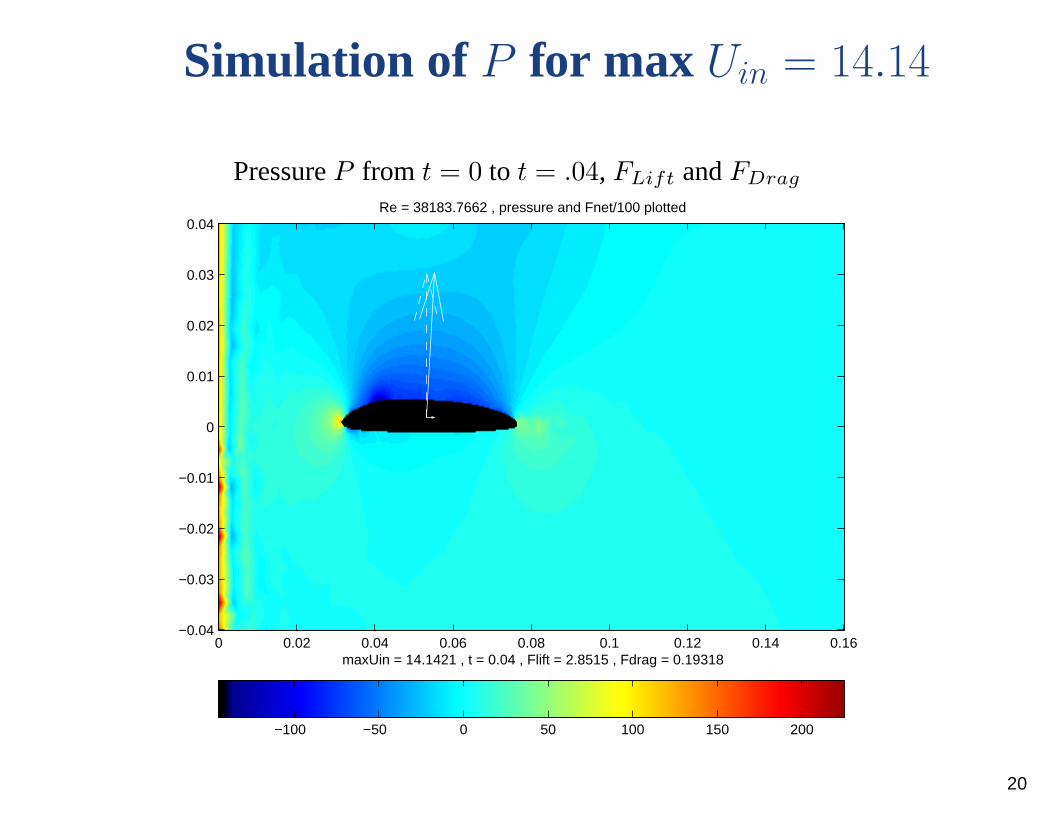
Simulation of P for max Uin = 14.14
PressureP from t = 0 to t = .04, FLift andFDrag
−100 −50 0 50 100 150 200
maxUin = 14.1421 , t = 0.04 , Flift = 2.8515 , Fdrag = 0.19318
Re = 38183.7662 , pressure and Fnet/100 plotted
0 0.02 0.04 0.06 0.08 0.1 0.12 0.14 0.16−0.04
−0.03
−0.02
−0.01
0
0.01
0.02
0.03
0.04
20

Simulation of |u| for max Uin = 5
Speed|u| from t = 0 to t = .04, FLift andFDrag
0 1 2 3 4 5 6 7 8 9 10
maxUin = 5 , t = 0.04 , Flift = 0.14187 , Fdrag = 0.025632
Re = 13500 , speed and Fnet/10 plotted
0 0.02 0.04 0.06 0.08 0.1 0.12 0.14 0.16−0.04
−0.03
−0.02
−0.01
0
0.01
0.02
0.03
0.04
21
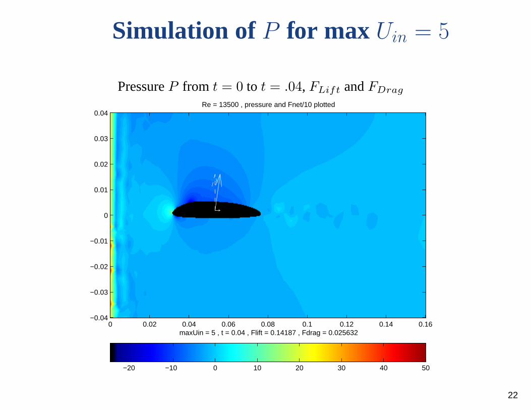
Simulation of P for max Uin = 5
PressureP from t = 0 to t = .04, FLift andFDrag
−20 −10 0 10 20 30 40 50
maxUin = 5 , t = 0.04 , Flift = 0.14187 , Fdrag = 0.025632
Re = 13500 , pressure and Fnet/10 plotted
0 0.02 0.04 0.06 0.08 0.1 0.12 0.14 0.16−0.04
−0.03
−0.02
−0.01
0
0.01
0.02
0.03
0.04
22
Simulation Comments
• Can see starting vortex shed off trailing edge• Pressure clearly lower above airfoil• Velocity also larger near top surface of airfoil• Thin boundary layer visible• Earlier boundary layer separation forRe = 13500 suggests inviscid
approximation not as good forRe in that range or smaller• Difficult to make simulation stable and accurate for high Reynolds
number flows• SimulatedFLift not exactly following theFLift ∝ U2 model, but we’ll
call it close enough
23

A Free-Body Diagram
If we assume the drag force is negligible, then the only forces we consider arethe lift force and the force due to gravity.
Assume the boomerang travels in a circular path and let the verticalcomponent of the lift force balance gravity. Then we are leftwith a net forcethat is parallel to the ground and can be thought of as a centripetal force.
24

A Top View of Boomerang Flight
Ω = rate of precession inradians/sec
Fnet = centripetal force
R = radius of theboomerang’s flight path
So why does the boomerang turn?
25
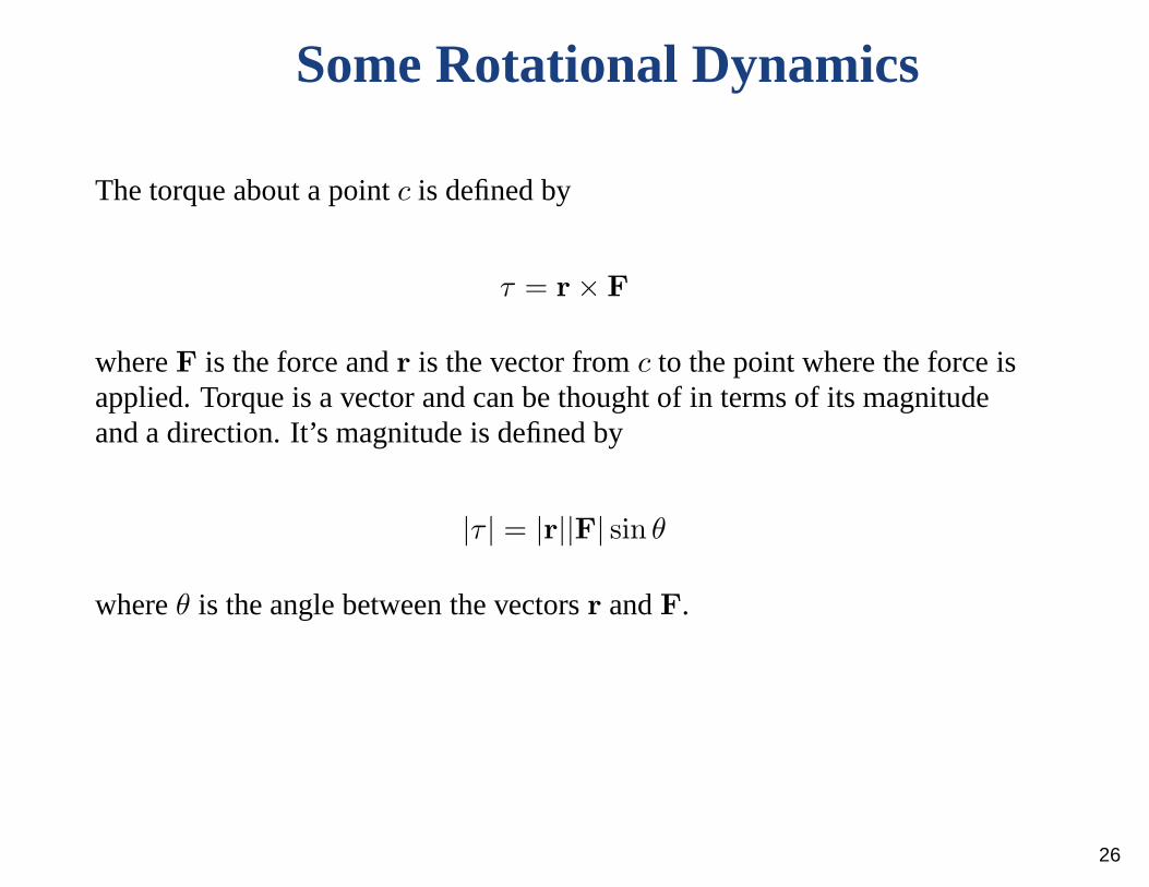
Some Rotational Dynamics
The torque about a pointc is defined by
τ = r × F
whereF is the force andr is the vector fromc to the point where the force isapplied. Torque is a vector and can be thought of in terms of its magnitudeand a direction. It’s magnitude is defined by
|τ | = |r||F| sin θ
whereθ is the angle between the vectorsr andF.
26
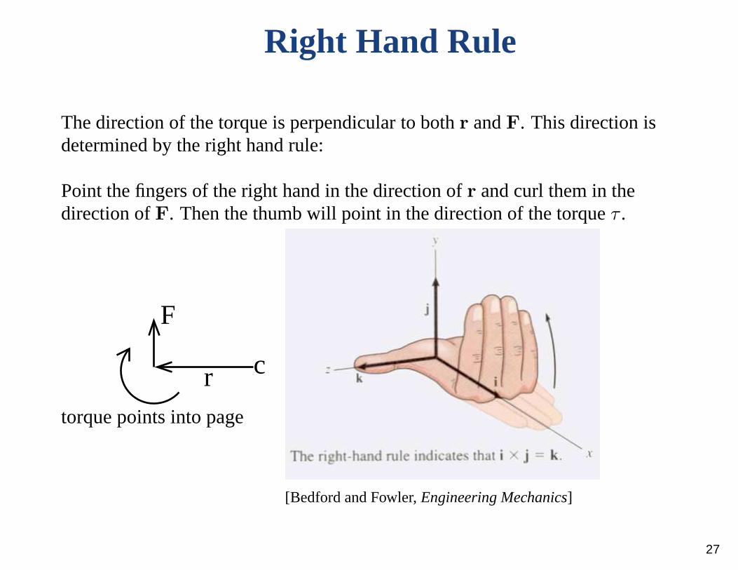
Right Hand Rule
The direction of the torque is perpendicular to bothr andF. This direction isdetermined by the right hand rule:
Point the fingers of the right hand in the direction ofr and curl them in thedirection ofF. Then the thumb will point in the direction of the torqueτ .
torque points into page
cr
F
[Bedford and Fowler,Engineering Mechanics]
27
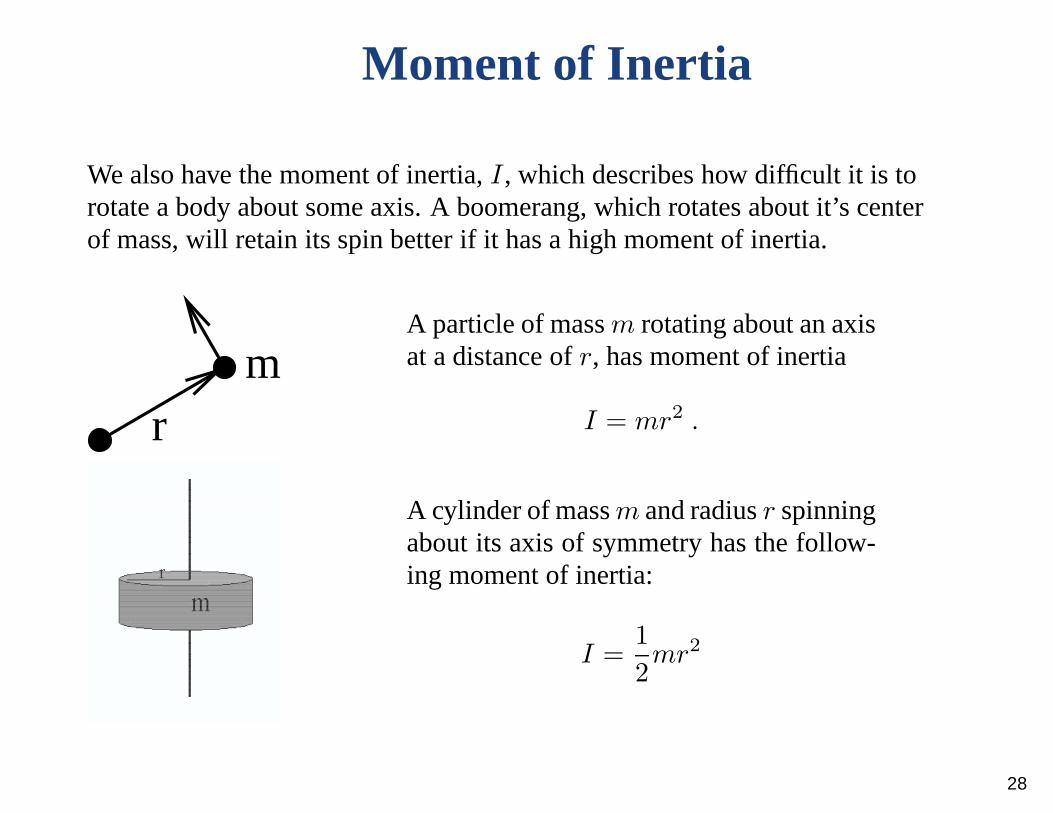
Moment of Inertia
We also have the moment of inertia,I, which describes how difficult it is torotate a body about some axis. A boomerang, which rotates about it’s centerof mass, will retain its spin better if it has a high moment of inertia.
rm
A particle of massm rotating about an axisat a distance ofr, has moment of inertia
I = mr2 .
A cylinder of massm and radiusr spinningabout its axis of symmetry has the follow-ing moment of inertia:
I =1
2mr2
28
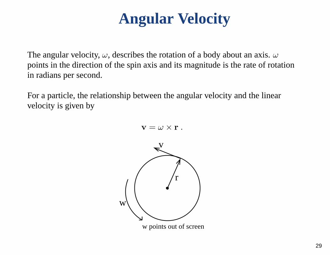
Angular Velocity
The angular velocity,ω, describes the rotation of a body about an axis.ω
points in the direction of the spin axis and its magnitude is the rate of rotationin radians per second.
For a particle, the relationship between the angular velocity and the linearvelocity is given by
v = ω × r .
w
r
v
w points out of screen
29

Angular MomentumThe angular momentum,J, is the rotational analogue to linear momentum.Angular momentum is conserved in the absence of external torque, analogousto how momentum is conserved in the absence of external forces. For aparticle, angular momentum is given by
J = r × p
wherep is the linear momentum of the particle andr is it’s location withrespect to some choice of origin.
For an object that is symmetricalabout its axis of rotation, the fol-lowing formula for angular momen-tum applies:
J = Iω
p points into screen
x
y
z
r
J
This formula also applies to planarbodies, such as a boomerang, rotat-ing about a perpendicular axis. Wetake the center of mass to be the ori-gin and letI refer to the moment ofinertia about the perpendicular axisthrough the center of mass. 30
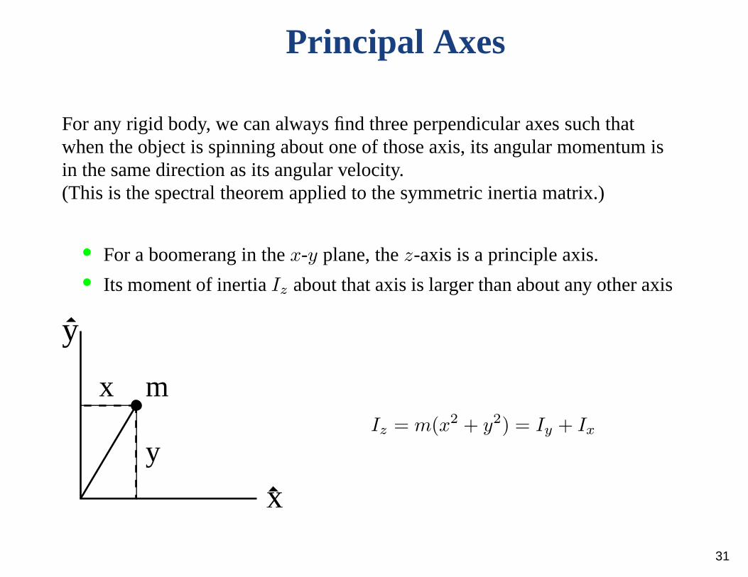
Principal Axes
For any rigid body, we can always find three perpendicular axes such thatwhen the object is spinning about one of those axis, its angular momentum isin the same direction as its angular velocity.(This is the spectral theorem applied to the symmetric inertia matrix.)
• For a boomerang in thex-y plane, thez-axis is a principle axis.• Its moment of inertiaIz about that axis is larger than about any other axis
y
mx
y
x
Iz = m(x2 + y2) = Iy + Ix
31
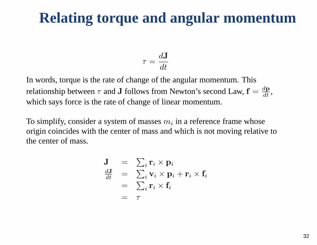
Relating torque and angular momentum
τ =dJ
dt
In words, torque is the rate of change of the angular momentum. Thisrelationship betweenτ andJ follows from Newton’s second Law,f = dp
dt,
which says force is the rate of change of linear momentum.
To simplify, consider a system of massesmi in a reference frame whoseorigin coincides with the center of mass and which is not moving relative tothe center of mass.
J =∑
i ri × pi
dJdt
=∑
i vi × pi + ri × fi
=∑
i ri × fi
= τ
32
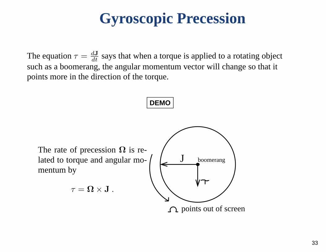
Gyroscopic Precession
The equationτ = dJdt
says that when a torque is applied to a rotating objectsuch as a boomerang, the angular momentum vector will changeso that itpoints more in the direction of the torque.
DEMO
The rate of precessionΩ is re-lated to torque and angular mo-mentum by
τ = Ω× J .
boomerang
points out of screen
J
33
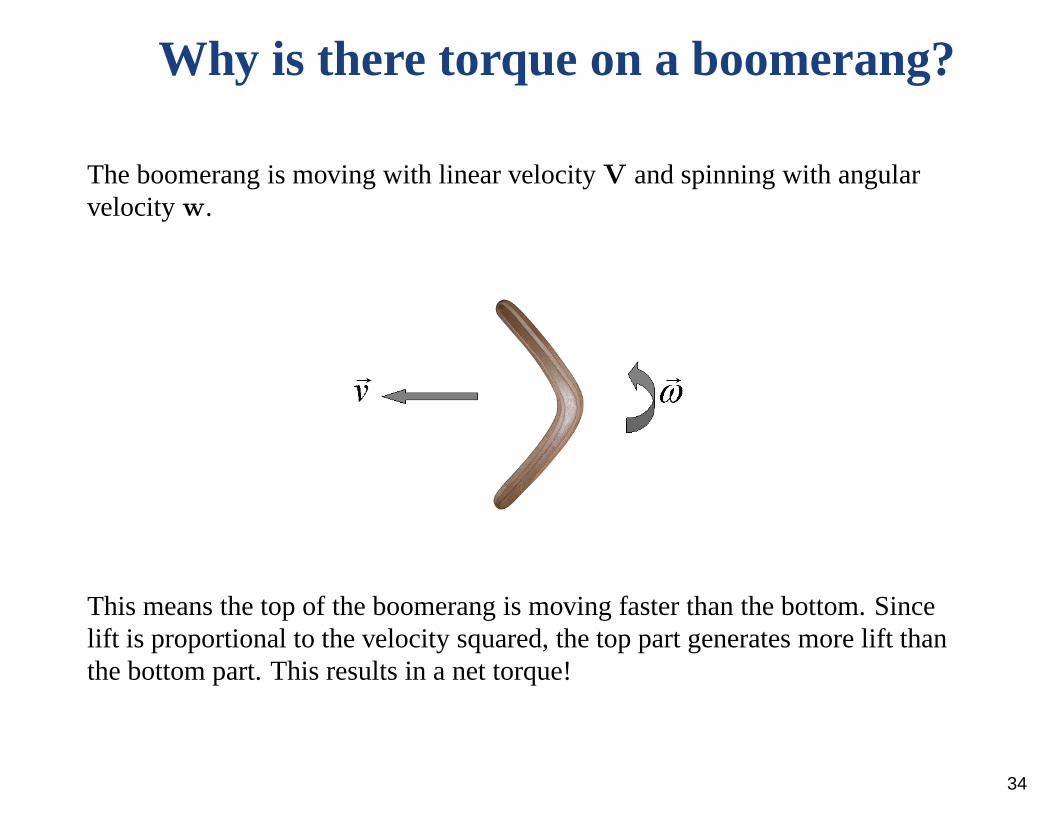
Why is there torque on a boomerang?
The boomerang is moving with linear velocityV and spinning with angularvelocityw.
This means the top of the boomerang is moving faster than the bottom. Sincelift is proportional to the velocity squared, the top part generates more lift thanthe bottom part. This results in a net torque!
34
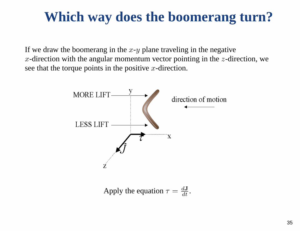
Which way does the boomerang turn?
If we draw the boomerang in thex-y plane traveling in the negativex-direction with the angular momentum vector pointing in thez-direction, wesee that the torque points in the positivex-direction.
Apply the equationτ = dJdt
.
35
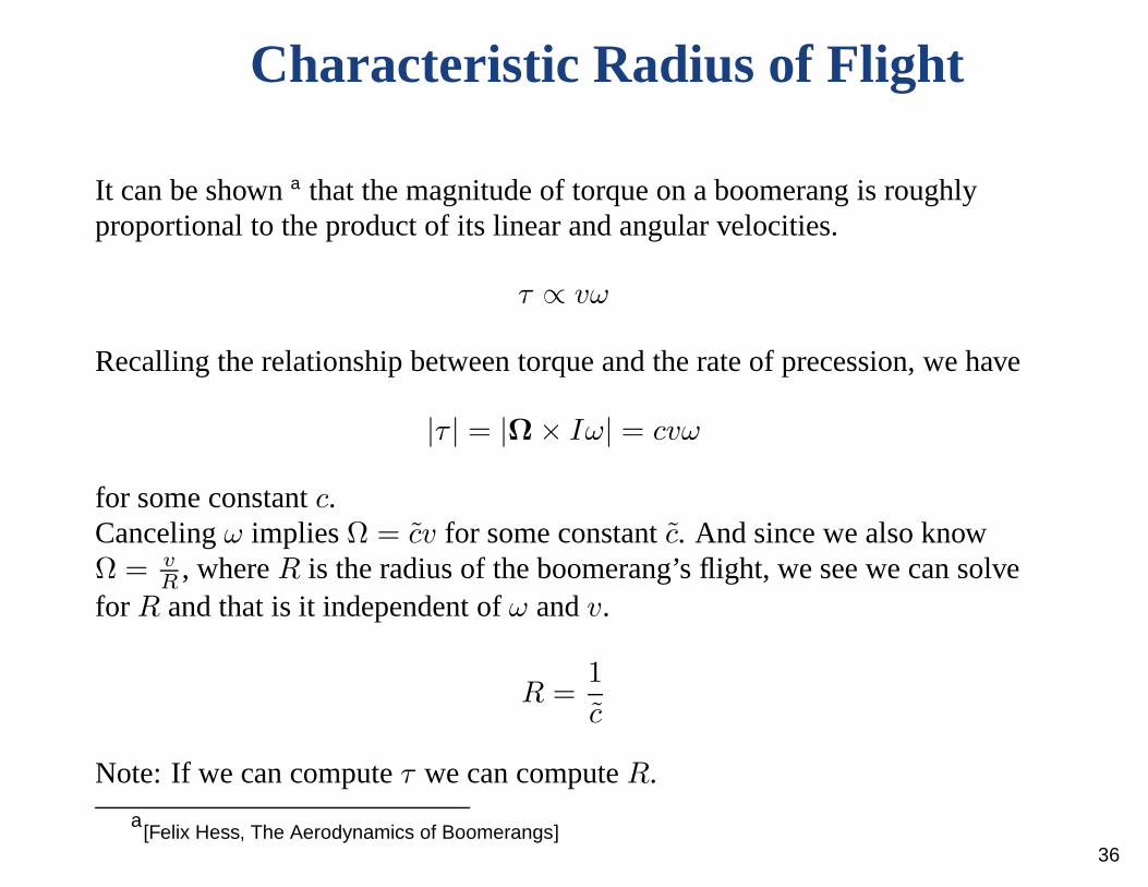
Characteristic Radius of Flight
It can be showna that the magnitude of torque on a boomerang is roughlyproportional to the product of its linear and angular velocities.
τ ∝ vω
Recalling the relationship between torque and the rate of precession, we have
|τ | = |Ω× Iω| = cvω
for some constantc.Cancelingω impliesΩ = cv for some constantc. And since we also knowΩ = v
R, whereR is the radius of the boomerang’s flight, we see we can solve
for R and that is it independent ofω andv.
R =1
c
Note: If we can computeτ we can computeR.
a[Felix Hess, The Aerodynamics of Boomerangs]
36
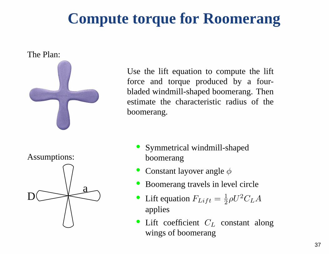
Compute torque for Roomerang
The Plan:
Use the lift equation to compute the liftforce and torque produced by a four-bladed windmill-shaped boomerang. Thenestimate the characteristic radius of theboomerang.
Assumptions:
Da
• Symmetrical windmill-shapedboomerang
• Constant layover angleφ• Boomerang travels in level circle
• Lift equationFLift = 1
2ρU2CLA
applies• Lift coefficient CL constant along
wings of boomerang37
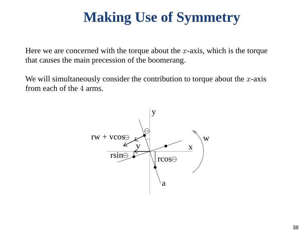
Making Use of Symmetry
Here we are concerned with the torque about thex-axis, which is the torquethat causes the main precession of the boomerang.
We will simultaneously consider the contribution to torqueabout thex-axisfrom each of the4 arms.
wrw + vcos
rsin rcos
x
y
a
v
38
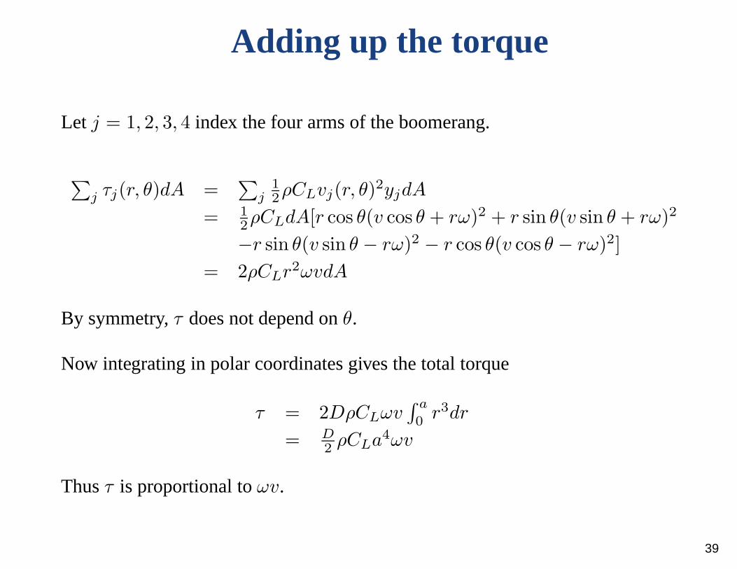
Adding up the torque
Let j = 1, 2, 3, 4 index the four arms of the boomerang.
∑j τj(r, θ)dA =
∑j
1
2ρCLvj(r, θ)
2yjdA
= 1
2ρCLdA[r cos θ(v cos θ + rω)2 + r sin θ(v sin θ + rω)2
−r sin θ(v sin θ − rω)2 − r cos θ(v cos θ − rω)2]
= 2ρCLr2ωvdA
By symmetry,τ does not depend onθ.
Now integrating in polar coordinates gives the total torque
τ = 2DρCLωv∫ a
0r3dr
= D2ρCLa4ωv
Thusτ is proportional toωv.
39
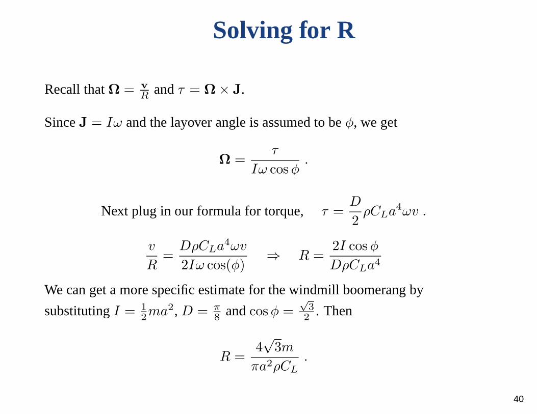
Solving for R
Recall thatΩ = vR
andτ = Ω × J.
SinceJ = Iω and the layover angle is assumed to beφ, we get
Ω =τ
Iω cosφ.
Next plug in our formula for torque, τ =D
2ρCLa4ωv .
v
R=
DρCLa4ωv
2Iω cos(φ)⇒ R =
2I cosφ
DρCLa4
We can get a more specific estimate for the windmill boomerangby
substitutingI = 1
2ma2, D = π
8andcosφ =
√
3
2. Then
R =4√
3m
πa2ρCL
.
40

Implications of the equation for R
R =2I cosφ
DρCLa4
• Under our assumptions,R is independent ofv andw. Thus the range ofa boomerang doesn’t depend on how it is thrown.R is instead a propertyof the boomerang itself.
• A larger moment of inertia implies a bigger radius.• Lower air density results in a larger radius.• More wing area gives the boomerang a smaller flight radius.• A larger lift coefficient also causes reduced range.
41
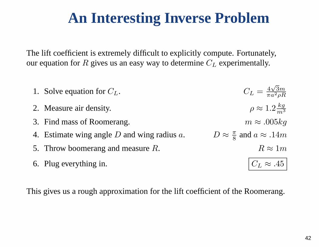
An Interesting Inverse Problem
The lift coefficient is extremely difficult to explicitly compute. Fortunately,our equation forR gives us an easy way to determineCL experimentally.
1. Solve equation forCL. CL = 4√
3mπa2ρR
2. Measure air density. ρ ≈ 1.2 kgm3
3. Find mass of Roomerang. m ≈ .005kg
4. Estimate wing angleD and wing radiusa. D ≈ π8
anda ≈ .14m
5. Throw boomerang and measureR. R ≈ 1m
6. Plug everything in. CL ≈ .45
This gives us a rough approximation for the lift coefficient of the Roomerang.
42

Extension to Classical Boomerang Shape
Without special symmetry, the lift force and torque produced by theboomerang depend on the angle of rotation. Felix Hess’s liftdiagram belowillustrates the non-symmetric lift force for the lifting arm as it sweeps out acircle. (The darker color corresponds to more lift.)
[Felix Hess,The Aerodynamics of Boomerangs]
The situation can be simplified by using time averages of liftand torque toapproximate the previous calculations.
43
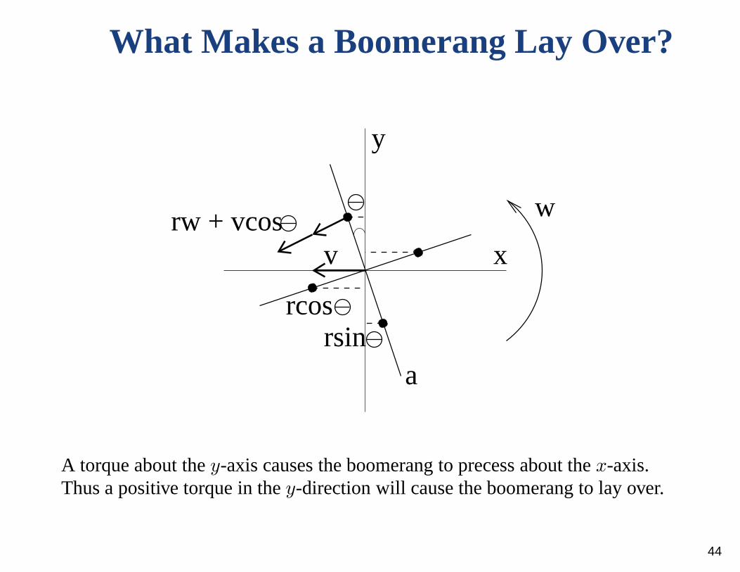
What Makes a Boomerang Lay Over?
vrw + vcos
x
y
a
rcosrsin
w
A torque about they-axis causes the boomerang to precess about thex-axis.Thus a positive torque in they-direction will cause the boomerang to lay over.
44
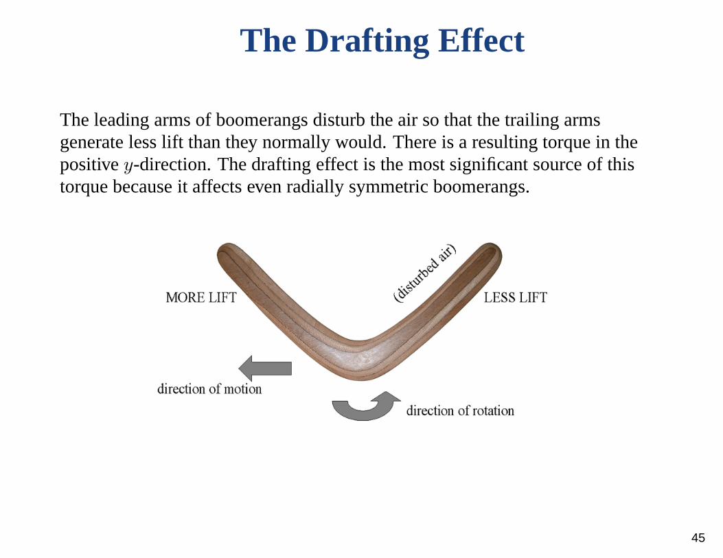
The Drafting Effect
The leading arms of boomerangs disturb the air so that the trailing armsgenerate less lift than they normally would. There is a resulting torque in thepositivey-direction. The drafting effect is the most significant source of thistorque because it affects even radially symmetric boomerangs.
45
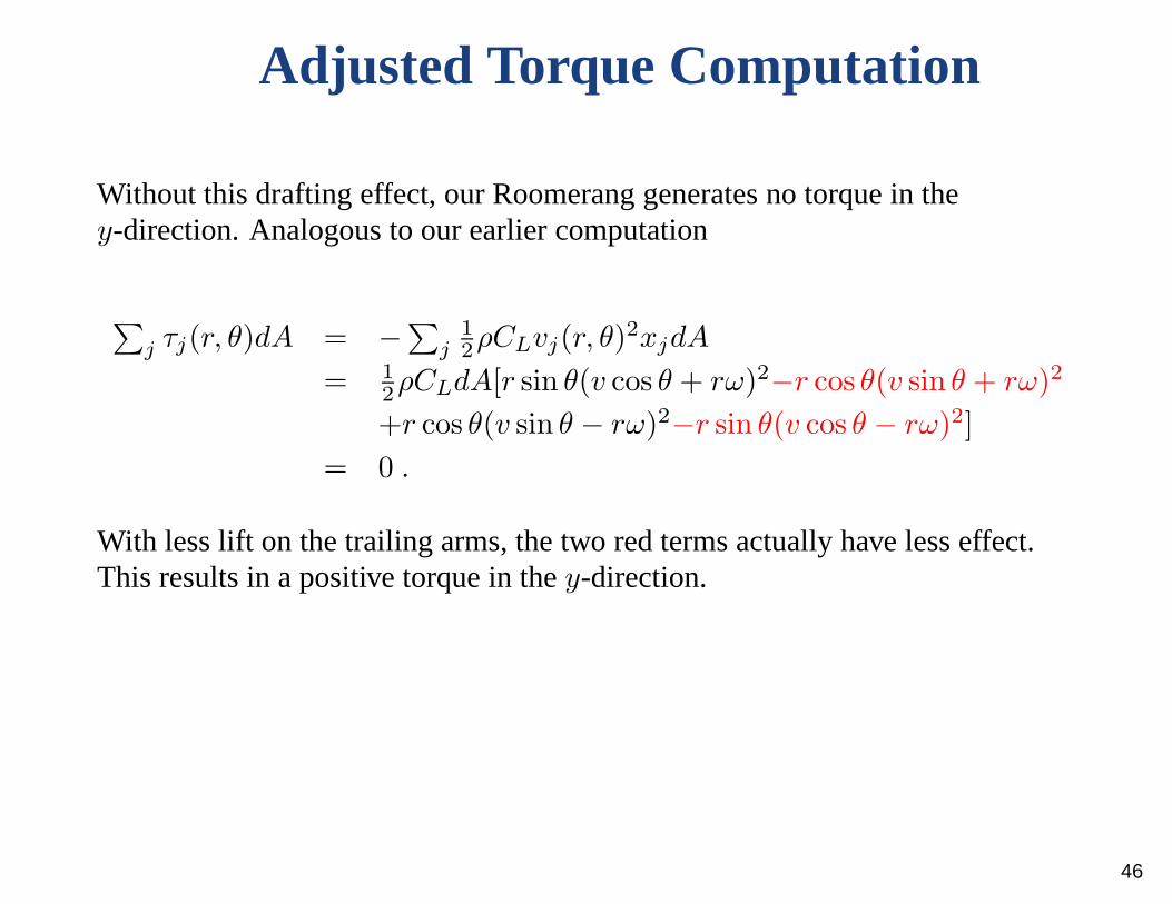
Adjusted Torque Computation
Without this drafting effect, our Roomerang generates no torque in they-direction. Analogous to our earlier computation
∑j τj(r, θ)dA = −∑
j1
2ρCLvj(r, θ)
2xjdA
= 1
2ρCLdA[r sin θ(v cos θ + rω)2−r cos θ(v sin θ + rω)2
+r cos θ(v sin θ − rω)2−r sin θ(v cos θ − rω)2]
= 0 .
With less lift on the trailing arms, the two red terms actually have less effect.This results in a positive torque in they-direction.
46

Eccentricity Torque
Eccentricity torque is only an issue with non-radially symmetric boomerangs,and is caused when there is unequal lift on arms with nonzero eccentricity.The eccentricity refers to the perpendicular distance between an arm and thecenter of mass.
If the lifting arm generates more lift than the dingle arm, the resulting torquein they-direction causes the boomerang to lay over faster.
47
Boomerang Construction and Tuning
Tools and Supplies:Warp-resistant plywood, coping saw (or bandsaw!), drill sander, wood file, knife, sandpaper,and patience.
WoodworkingIrreversibility:
Err on the side of removing less wood for thefirst test flight, because it’s easy to take woodoff but challenging to put it back on.
Adjusting WeightDistribution:
• Adding mass to the ends of armsincreases the moment of inertia resultingin longer range and better windresistance.
• Adding mass to center improves windresistance and stability.
• A lot of very fine tuning can be accom-plished by adding small weights to vari-ous parts of a boomerang.
48
Adjusting Lift Properties
• We can alter the shape of the bevels and airfoils to increase or decreasethe lift generated.
• More lift on the lifting arm yields a faster layover.• More lift on the dingle arm results in less layover and a flatter, more
circular flight.• Larger bevels increase lift and torque, causing the boomerang to make a
tighter turn.• Too much lift can cause too tight of an orbit.• Streamlining is important and can sometimes save a boomerang that
prematurely runs out of spin.• Conversely, a rougher surface isn’t necessarily bad and canoccasionally
improve flight characteristics.
49

Warping Effects
A warped boomerang is not necessarily a broken boomerang.
• A warped boomerang that is concave up will have reduced range, but aconcave down boomerang might not fly at all.
• The arms of a boomerang can be twisted to give them a positive ornegative angle of attack.
• More fine tuning can also be accomplished by turning the tips of thearms up or down.
• A warping caution: I’ve found that intentionally warping a boomerang isoften only a temporary change, and the results can be inconsistent.
50

General Throwing Tips
Two Throwing Grips:
The Throwing Angle
[Aboriginal Steve’s boomerang
page]
51
Throwing and Troubleshooting
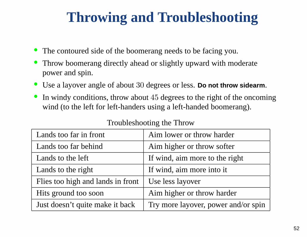
• The contoured side of the boomerang needs to be facing you.• Throw boomerang directly ahead or slightly upward with moderate
power and spin.• Use a layover angle of about30 degrees or less.Do not throw sidearm.• In windy conditions, throw about45 degrees to the right of the oncoming
wind (to the left for left-handers using a left-handed boomerang).
Troubleshooting the Throw
Lands too far in front Aim lower or throw harder
Lands too far behind Aim higher or throw softer
Lands to the left If wind, aim more to the right
Lands to the right If wind, aim more into it
Flies too high and lands in front Use less layover
Hits ground too soon Aim higher or throw harder
Just doesn’t quite make it back Try more layover, power and/or spin
52

A Word on Catching and Safety
A Good Catch
[Hawes,All About Boomerangs]
Throw in a large open area devoid of potential boomerang victims (people,windows, anything expensive) as well as boomerang predators (power lines,trees, pit bulls). Only one boomerang at a time should be in the air so that noone’s attention is dangerously divided.
53

DO NOT GET DISTRACTED!
Always keep your eyes on a thrown boomerang. It has a tendencyto comeback. Either catch it, dodge it or protect yourself!
54
References
• Acheson, D.J.Elementary Fluid Dynamics,2005.• Boomerang Passion [http://www.boomerangpassion.com/english.php]• European Boomerang Links
[http://www.flight-toys.com/boomerang/europe.htm]• Hawes, Lorin Lindley and Mauro, John,All About Boomerangs, 1987.• Hess, Felix,The Aerodynamics of Boomerangs, 1968.• Hunt, Hugh,Unspinning the Boomerang• Landau and Lifshitz,Mechanics• Majda, Andrew J. and Bertozzi, Andrea L.Vorticity and Incompressible
Flow, 2002.• Pakalnis, Saulius,Aerodynamics of Boomerang,
[http://researchsupporttechnologies.com/boomerang_site/boomerang1.htm]• Persson, Per-Olof, and Strang, Gilbert.
[http://www-math.mit.edu/ persson/mesh/]• Reid, Robert,The Physics of Boomerangs, 1984.
55
Top Related