


Languages
Pages
Legal

*-
(&)Westinghouse
U.S. Nuclear Regulatory Commission Document Control Desk Washington, D.C. 20555
SUBJECT:
Westinghouse Electric Company Nuclear Plant Projects PO Box355 Pittsburgh, Pennsylvania 15230-0355 USA
Direct tel: Direct fax.
Your ref: Our ref:
412-374-5355 412-374-5456 [email protected]
DCP/NRC1520
August 22, 2002
Transmittal of Westinghouse Document, "Design Process for AP1000 Common Q Safety Systems," WCAP-15927, Rev. 0, Non-Proprietary, dated August 2002
Enclosed please the Westinghouse document, "Design Process for AP1000 Common Q Safety Systems," WCAP-15927, Revision 0, Non-Proprietary, dated August 2002. This document was referenced in Section 7.1 of the AP1000 Design Control Document Revision 2 as Reference 10 NABU-DP-00014-GEN, Revision 0. However, this document had not been previously submitted to the NRC, and it is therefore submitted with this transmittal as WCAP-15927. Reference 10 in DCD Section 7.1 will be revised to reflect the updated document number.
Please contact me at 412-374-5355 if you have any questions concerning this submittal.
Very truly yours,
M. M. Corletti Passive Plant Projects & Development AP600 & AP1000 Projects
/Attachment 1. WCAP-15927, Rev. 0, "Design Process for AP1000 Common Q Safety Systems," dated
August 2002
A BNFL Group company-D (:ý0'5
2902alf doc
DCP/NRC1520
August 22, 2002
Attachment 1
WCAP-15927, Rev. 0
"Design Process for AP1000 Common Q Safety Systems"
August 2002
2896alfdoc
August 2002WCAP-15927
Design Process for AP1000 Common Q
Safety Systems
* Westinghouse
Westinghouse Non-Proprietary Class 3
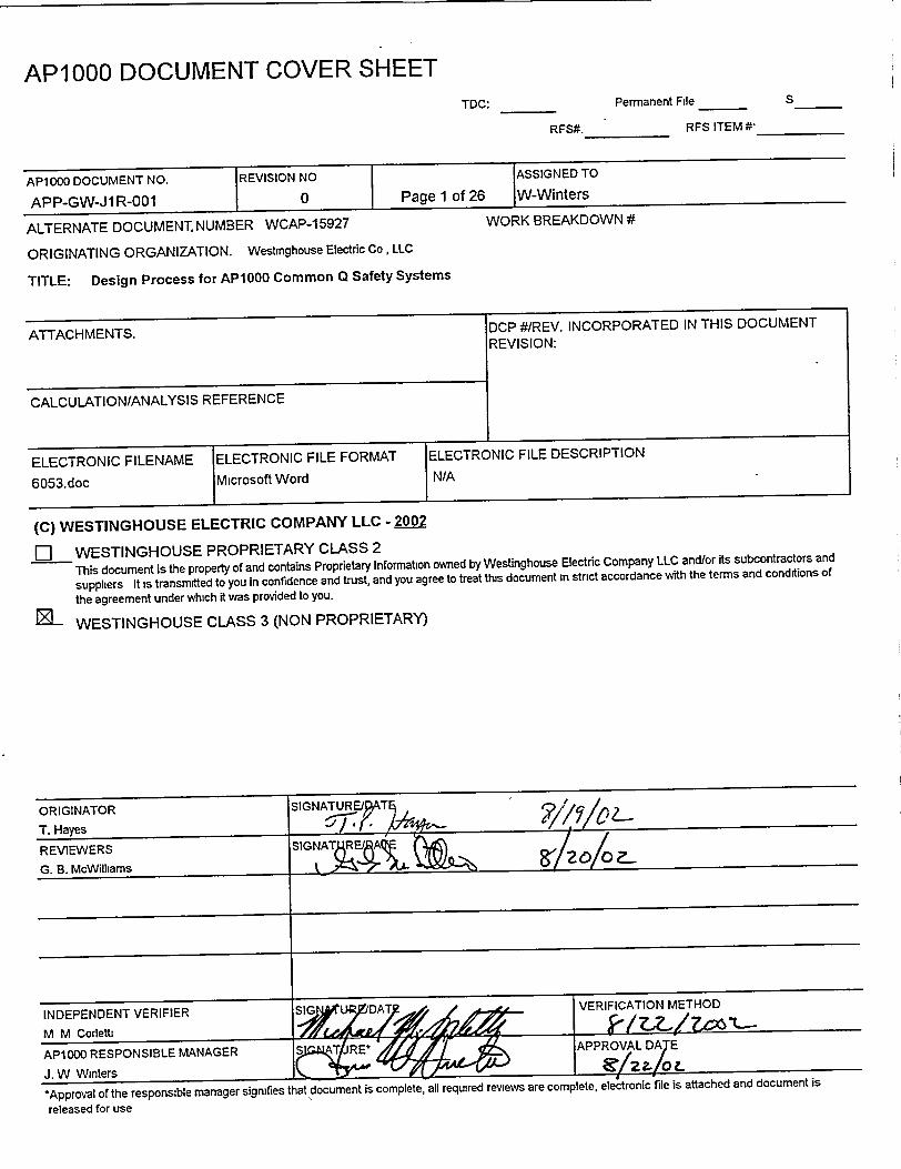
AP1000 DOCUMENT COVER SHEETTDC:
RFS#.
Permanent File
RFS ITEM #*
AP1000 DOCUMENT NO. REVISION NO
APP-GW-J1 R-001 I 0
ALTERNATE DOCUMENT. NUMBER WCAP-15927
ASSIGNED TO
Page 1 of 26 1lW-Winters
WORK BREAKDOWN #
ORIGINATING ORGANIZATION. Westinghouse Electric Co, LLC
TITLE: Design Process for AP1000 Common Q Safety Systems
ATTACHMENTS.
CALCULATIONIANALYSIS REFERENCE
ELECTRONIC FILENAME ELECTRONIC FILE FORMAT ELECTR(
6053.doc Microsoft Word N/A
DCP #/REV. INCORPORATED IN THIS DOCUMENT REVISION:
ONIC FILE DESCRIPTION
(C) WESTINGHOUSE ELECTRIC COMPANY LLC - 2002
[1 WESTINGHOUSE PROPRIETARY CLASS 2
This document is the property of and contains Proprietary Information owned by Westinghouse Electric Company LLC and/or its subcontractors and
suppliers It is transmitted to you in confidence and trust, and you agree to treat this document in strict accordance with the terms and conditions of
the agreement under which it was provided to you.
WESTINGHOUSE CLASS 3 (NON PROPRIETARY)
S
I
WESTINGHOUSE NON-PROPRIETARY CLASS 3
WCAP-15927
Design Process for AP1000 Common Q Safety Systems
T. P. Hayes Passive Plant Projects and Development
August 2002
Revi ewer:'-d.-Ql(& Gary B. Mc~illiams, Principle Engineer RPS and PAMS Systems
Approved: J. W. Winters, Managerg Passive Plant Projects and Development
Westinghouse Electric Company LLC P.O. Box 355
Pittsburgh, PA 15230-0355
© 2002 Westinghouse Electric Company LLC All Rights Reserved
6053 doc-081902
WCAP-1 5927 API000 APP-GW-J1R-001
TABLE OF CONTENTS
LIST OF FIGURES ............................................................................................... iv
I INTRODUCTION AND SCOPE .............................................................................................. 1
2 D EFIN ITION S ....................................................................................................... ........ 3
2.1 A CR O N Y M S ..................................................................................................................... 3
2 .2 T E R M S ........................................................................................................... .................. 3
3 AP 1000 SPECIFIC APPLICATION DEVELOPMENT ........................................................... 4
3.1 CONCEPTUAL PHASE ....................................................................................... 4
3.2 SYSTEM DEFINITION PHASE ...................... ....... ........ 5
3.2.1 System Requirements Analysis ...................................................................... 5
3.2.2 System Architectural Design ......................................................................... 8
3.2.3 Software Requirements Analysis ................................................................ 10
3.3 SOFTWARE DESIGN PHASE ................................................................................... 10
3.4 HARDWARE DESIGN PHASE .................................................................................. 11"
3.5 SOFTWARE IMPLEMENTATION PHASE .................................................................... 11
3.6 HARDWARE IMPLEMENTATION (ASSEMBLY) PHASE .................. 2...... .
3.7 SYSTEM INTEGRATION PHASE ............................................................................. 12
3.8 INSTALLATION PHASE ............................................................................................ 12
4 PLATFORM DEVELOPMENT .................................................................................................... 15
4.1 CONCEPTUAL PHASE .............................................................................................. 16
4.2 PLATFORM REQUIREMENTS ANALYSIS PHASE .............................................. 16
4.2.1 Platform System Design Requirements ....................................................... 16
4.2.2 I&C Product Requirements ......................................................................... 17
4.3 PRODUCT SELECTION PHASE ............................................................................ 17
4.4 PLATFORM SYSTEM ARCHITECTURAL DESIGN PHASE ................................ 17
4.5 HARDWARE REQUIREMENTS ANALYSIS PHASE ............................................ 18
4.6 HARDWARE DESIGN PHASE .................................................................................. 18
4.7 HARDWARE IMPLEMENTATION PHASE ............................................................. 19
4.8 SOFTWARE REQUIREMENTS ANALYSIS ............................................................. 19
4.8.1 TypeSpec (Summary and Requirements) ................................................... 19
4.8.2 Software Requirements Specification ........................................................ 20
4.9 SOFTWARE DESIGN PHASE .................................................................................. 20
4.9.1 TypeSpec (Design information) ................................................................. 20
4.9.2 Software Design Description ...................................................................... 20
4.10 SOFTWARE IMPLEMENTATION PHASE ............................................................... 21
5 REFERENCES ............................................................................................. 23
5.1 INDUSTRY STANDARDS AND CODES ...................................................................... 23
5.2 WESTINGHOUSE DOCUMENTS ........................................................................... 23
Revision 0
6053 doc-081902
WCAP-15927 APP-GW-JIR-001 AP1000
LIST OF FIGURES
Figure 1 Application Development Process .......................................................................... 13
Figure 2 Correlation to Standard Life Cycle Phases........................................................ 14
Figure 3 -Platform Development Process .......................................................................... 22
Revision 0 iv 6053 doc-081902
WCAP-15927 AP1000 APP-GW-JIR-001
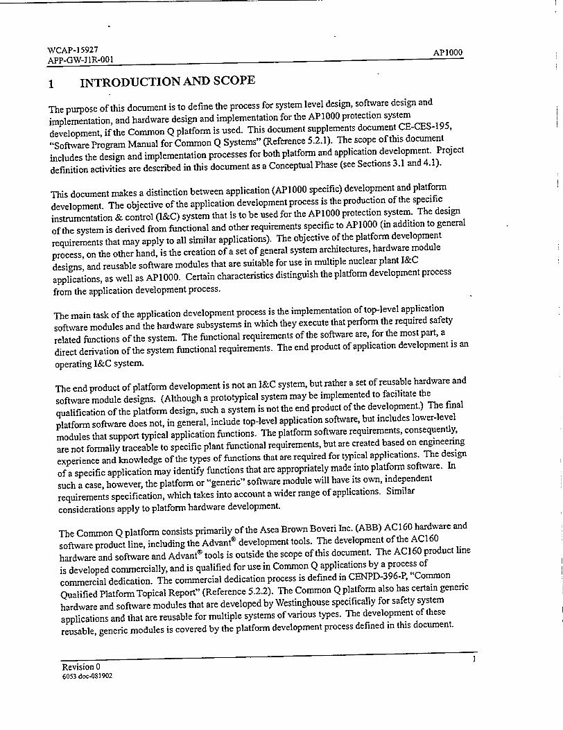
1 INTRODUCTION AND SCOPE
The purpose of this document is to define the process for system level design, software design and
implementation, and hardware design and implementation for the AP1000 protection system
development, if the Common Q platform is used. This document supplements document CE-CES-195,
"Software Program Manual for Common Q Systems" (Reference 5.2.1). The scope of this document
includes the design and implementation processes for both platform and application development. Project
definition activities are described in this document as a Conceptual Phase (see Sections 3.1 and 4.1).
This document makes a distinction between application (AP1000 specific) development and platform
development. The objective of the application development process is the production of the specific
instrumentation & control (I&C) system that is to be used for the AP 1000 protection system. The design
of the system is derived from functional and other requirements specific to AP1000 (in addition to general
requirements that may apply to all similar applications). The objective of the platform development
process, on the other hand, is the creation of a set of general system architectures, hardware module
designs, and reusable software modules that are suitable for use in multiple nuclear plant I&C
applications, as well as AP1000. Certain characteristics distinguish the platform development process
from the application development process.
The main task of the application development process is the implementation of top-level application
software modules and the hardware subsystems in which they execute that perform the required safety
related functions of the system. The functional requirements of the software are, for the most part, a
direct derivation of the system functional requirements. The end product of application development is an
operating I&C system.
The end product of platform development is not an I&C system, but rather a set of reusable hardware and
software module designs. (Although a prototypical system may be implemented to facilitate the
qualification of the platform design, such a system is not the end product of the development.) The final
platform software does not, in general, include top-level application software, but includes lower-level
modules that support typical application functions. The platform software requirements, consequently,
are not formally traceable to specific plant functional requirements, but are created based on engineering
experience and knowledge of the types of functions that are required for typical applications. The design
of a specific application may identify functions that are appropriately made into platform software. In
such a case, however, the platform or "generic" software module will have its own, independent
requirements specification, which takes into account a wider range of applications. Similar
considerations apply to platform hardware development.
The Common Q platform consists primarily of the Asea Brown Boveri Inc. (ABB) AC 160 hardware and
software product line, including the Advant® development tools. The development of the AC160
hardware and software and Advant® tools is outside the scope of this document. The AC160 product line
is developed commercially, and is qualified for use in Common Q applications by a process of
commercial dedication. The commercial dedication process is defined in CENPD-396-P, "Common
Qualified Platform Topical Report" (Reference 5.2.2). The Common Q platform also has certain generic
hardware and software modules that are developed by Westinghouse specifically for safety system
applications and that are reusable for multiple systems of various types. The development of these
reusable, generic modules is covered by the platform development process defined in this document.
Revision 0 6053 doc-0$1902
WCAP-1 5927 APIOOO APP-GW-J1R-001
The Common Q platform also contains certain components that are not ABB AC 160/Advant® commercial
components; examples include the Flat Panel Display and the human system interface (HSI) products
based on it, for example, Maintenance and Test Panel and QDPS display module. These products also
contain commercially dedicated elements, generic (Westinghouse-developed) platform software, and
API 000-specific software.
Revision 02 6053.doc-081902
WCAP-15927 AP1000 APP-GW-J1R-001
2 DEFINITIONS
2.1 ACRONYMS
ABB Asea Brown Boveri Inc.
AC 160 Part of the ABB Advant® open control system family product line
AFIO0 Advant® FieldBus
AMPL ABB/Advant® Master Programming Language
COTS Commercial Off-the-Shelf
DCD Design Control Document
EMC Electromagnetic Compatibility
HSI Human System Interface
HSL High Speed Datalink
I&C Instrumentation & Control
SAT Site Acceptance Testing
SDD Software Design Description
SSD System Specification Document
V&V Verification and Validation
2.2 TERMS
Advant® An ABB open control system family product line
Common Q Common Qualified Platform-a safety system I&C platform as defined in CENPD-396-P,
"Common Qualified Platform Topical Report" (Reference 5.2.2)
Revision 0
6053 doc-081902
WCAP-15927 AP1000 APP-GW-JIR-001
3 AP1000 SPECIFIC APPLICATION DEVELOPMENT
This section defines the process that is followed in the design of the AP1000 protection system and in the
design and implementation of application hardware and software that are specific to API000. The
relationship of hardware, software, and system verification and validation (including testing) to this
development pr6cess is shown, but the details are defined by the Verification and Validation (V&V) Plan.
The following phases occur in the development of application hardware and software:
1. Conceptual (Project Definition) 2. System Definition 3. Software Design 4. Hardware Design 5. Software Implementation 6. Hardware Implementation 7. System Integration 8. Installation
Testing activities are also defined as part of the V&V process. The testing activities complement the
hardware implementation, software implementation, system integration, and installation phases.
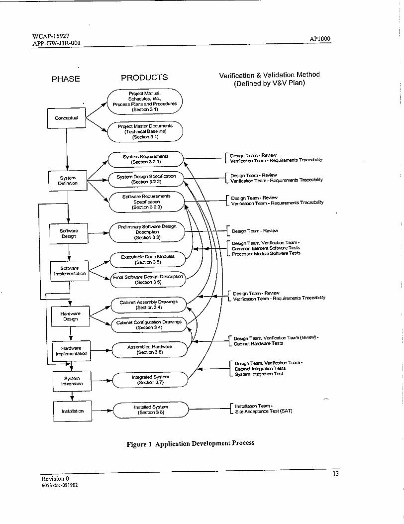
Figure 1 illustrates the relationship of the application development phases to each other and to the V&V
process. It also shows the outputs of each phase. The activities and products of these phases are
described in the remainder of this section. The flow of activities shown in Figure 1 is similar to that of a
classic "waterfall" development process. It is intended, however, that these activities may be both
iterative and overlapping In particular, because of the constraints of I&C projects, and considering the
distributed character of the AP1000 I&C systems, work may commence on a given development phase
before preceding phases are complete. For example, it is not necessary for the documentation of system
functional requirements to be finished before software design and implementation can start on parts of the
system for which the requirements have been defined.
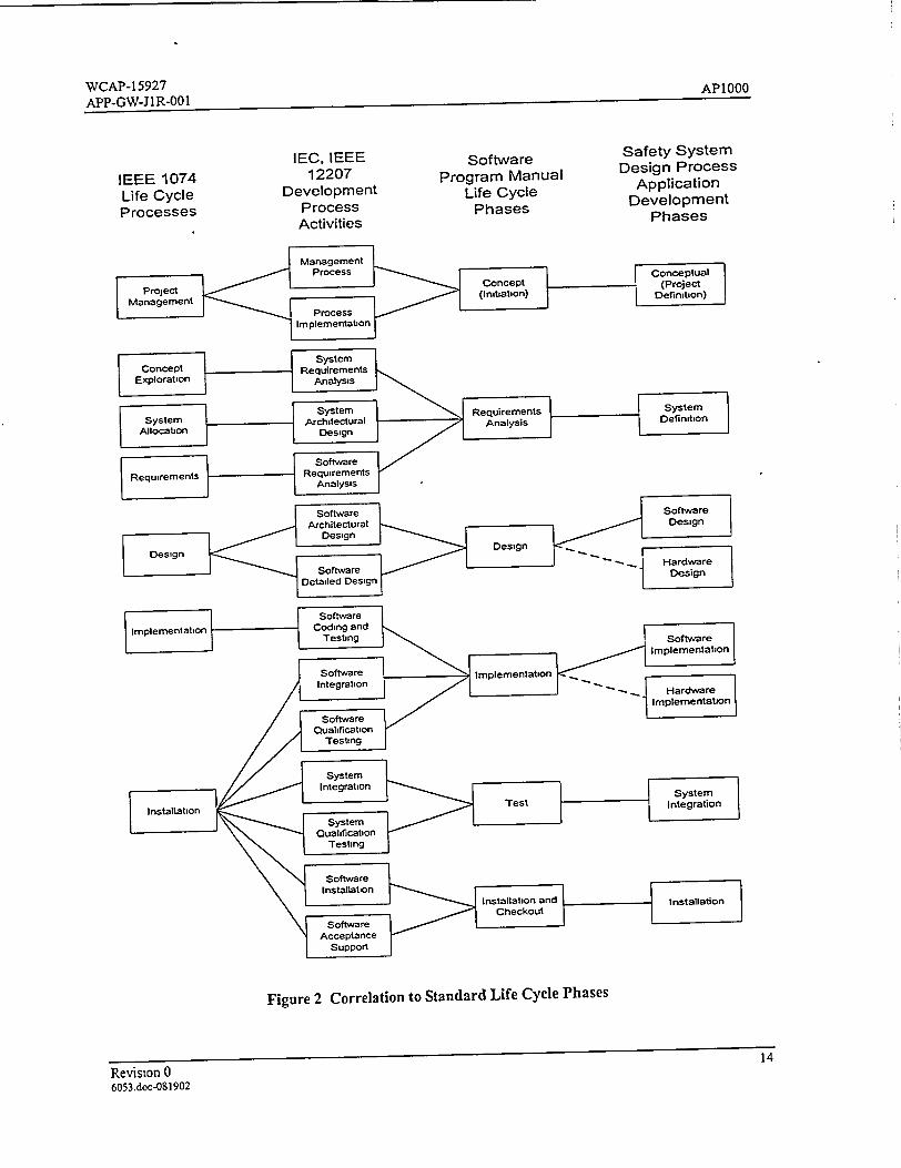
Figure 2 illustrates the relationship of the development phases defined in this document to the phases (or
processes) defined in other documents, specifically IEEE Std. 1074-1995, "IEEE Standard for Developing
Life Cycle Processes" (Reference 5.1.1); IEEE/EIA 12207.0-1996, "Industry Implementation of
International Standard ISO/IEC 12207: 1995 (ISO/IEC 12207) Standard for Information Technology
Software Life Cycle Processes" (Reference 5.1.2) and CE-CES-195, "Software Program Manual for
Common Q Systems" (Reference 5.2.1).
3.1 CONCEPTUAL PHASE
The major tasks of the conceptual, or project definition, phase are project management planning and
project baselining.
The project execution strategy is established and documented. Resources, personnel, and organizational
interfaces and dependencies are identified. Planning for schedule, costs, risk management,
communication, and project closure is done. Requisite processes are identified, and may include
Revision 0 6053.doc-081902
WCAP-15927 AP1000 APP-GW-] lR-001
acquisition, supply, development, operation, and maintenance, and the supporting processes of
configuration management, quality assurance, safety, verification, validation, and problem resolution.
The technical baseline is established and documented in Project Master Documents. Information in the
Project Master Documents defines the design requirements and includes:
* Definition of the scope of the development.
0 AP 1000 Design Control Document (DCD).
0 System Specification Documents (SSDs).
0 Safety classification of all parts of the system included in the scope of development.
* Plant documentation and databases.
• Plant-wide I&C requirements.
* Applicability of codes and standards, including decomposition of key codes and standards to
specific requirements.
3.2 SYSTEM DEFINITION PHASE
There are three main tasks in the system definition phase-system requirements analysis, system
architectural design, and software requirements analysis. These three tasks overlap in their execution, and
there may be considerable iteration among them. The output of this phase is a System Requirements
document, a System Design Specification, and a Software Requirements Specification.
3.2.1 System Requirements Analysis
In this task, the project technical baseline (Section 3.1) is analyzed to specify the system requirements.
This task produces the System Requirements document. Information in the System Requirements
document includes system design requirements, system functional requirements (including function
related setpoints and constants), system interface requirements, and human system interface (HSI)
requirements. Detailed requirements for the interface of individual external signals and communications
data is documented in an External Signal Database and an External Communications Database.
3.2.1.1 System Design Requirements
The system design requirements comprise the overall requirements and constraints for the system design,
aside from the specific system functions and specific interface signals. The application System
Requirements document incorporates, by reference, the Platform System Design Requirements and
Revision 0 5
6053 doc-081902
WCAP-15927 APP-GW-J IR-001 APl100
identifies additions and/or exceptions that apply specifically to AP1000. The system design requirements
(platform and applications) include the following categories of requirements:
* Applicability of codes and standards, either in whole, or in part, or as guidance (which may be
defined by reference to the applicability documented in the technical baseline).
* General design requirements: design basis, single failure criteria, integrity, independence,
maintenance, manual capabilities, information display, access control, identification, calibration
capabilities, reliability, and availability.
0 Hardware qualification: environmental, electromagnetic compatibility (EMC), and seismic.
0 Power and grounding.
* External interface capabilities.
9 Performance requirements: time response, accuracy, and signal noise.
* Test and diagnostic capabilities.
* Design constraints and objectives.
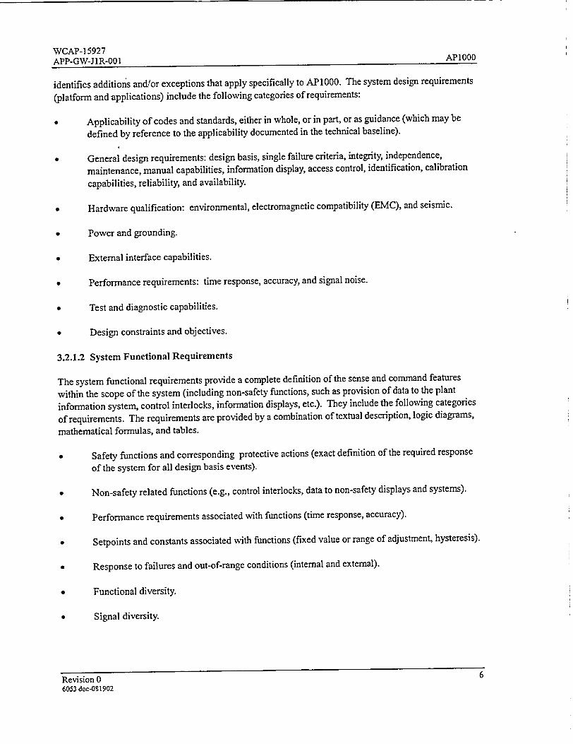
3.2.1.2 System Functional Requirements
The system functional requirements provide a complete definition of the sense and command features
within the scope of the system (including non-safety functions, such as provision of data to the plant
information system, control interlocks, information displays, etc.). They include the following categories
of requirements. The requirements are provided by a combination of textual description, logic diagrams,
mathematical formulas, and tables.
* Safety functions and corresponding protective actions (exact definition of the required response
of the system for all design basis events).
• Non-safety related functions (e.g., control interlocks, data to non-safety displays and systems).
* Performance requirements associated with functions (time response, accuracy).
* Setpoints and constants associated with functions (fixed value or range of adjustment, hysteresis).
* Response to failures and out-of-range conditions (internal and external).
* Functional diversity.
* Signal diversity.
Revision 0 6 6053 doc-081902
WCAP-15927 API000 APP-GW-J IR-001
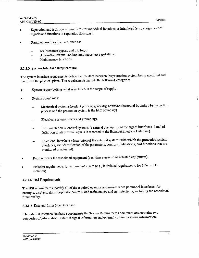
Separation and isolation requirements for individual functions or interfaces (e.g., assignment of
signals and functions to separation divisions).
* Required auxiliary features, such as:
- Maintenance bypass and trip logic - Automatic, manual, and/or continuous test capabilities - Maintenance functions
3.2.1.3 System Interface Requirements
The system interface requirements define the interface between the protection system being specified and
the rest of the physical plant. The requirements include the following categories:
* System scope (defines what is included in the scope of supply
System boundaries:
- Mechanical system (the plant process; generally, however, the actual boundary between the
process and the protection system is the I&C boundary).
- Electrical system (power and grounding).
- Instrumentation & control systems (a general description of the signal interfaces-detailed
definition of all external signals is recorded in the External Interface Database).
- Functional interfaces (description of the external systems with which the protection system
interfaces, and identification of the parameters, controls, indications, and functions that are
monitored or actuated).
Requirements for associated equipment (e.g., time response of actuated equipment).
Isolation requirements for external interfaces (e.g., individual requirements for I E-non I E
isolation).
3.2.1.4 HSI Requirements
The HSI requirements identify all of the required operator and maintenance personnel interfaces, for
example, displays, alarms, operator controls, and maintenance and test interfaces, including the associated
functionality.
3.2.1.5 External Interface Database
The external interface database supplements the System Requirements document and contains two
categories of information: external signal information and external communications information.
Revision 07 6053 doc-051902
WCAP-15927 APP-GW-J1R-001 AP1000
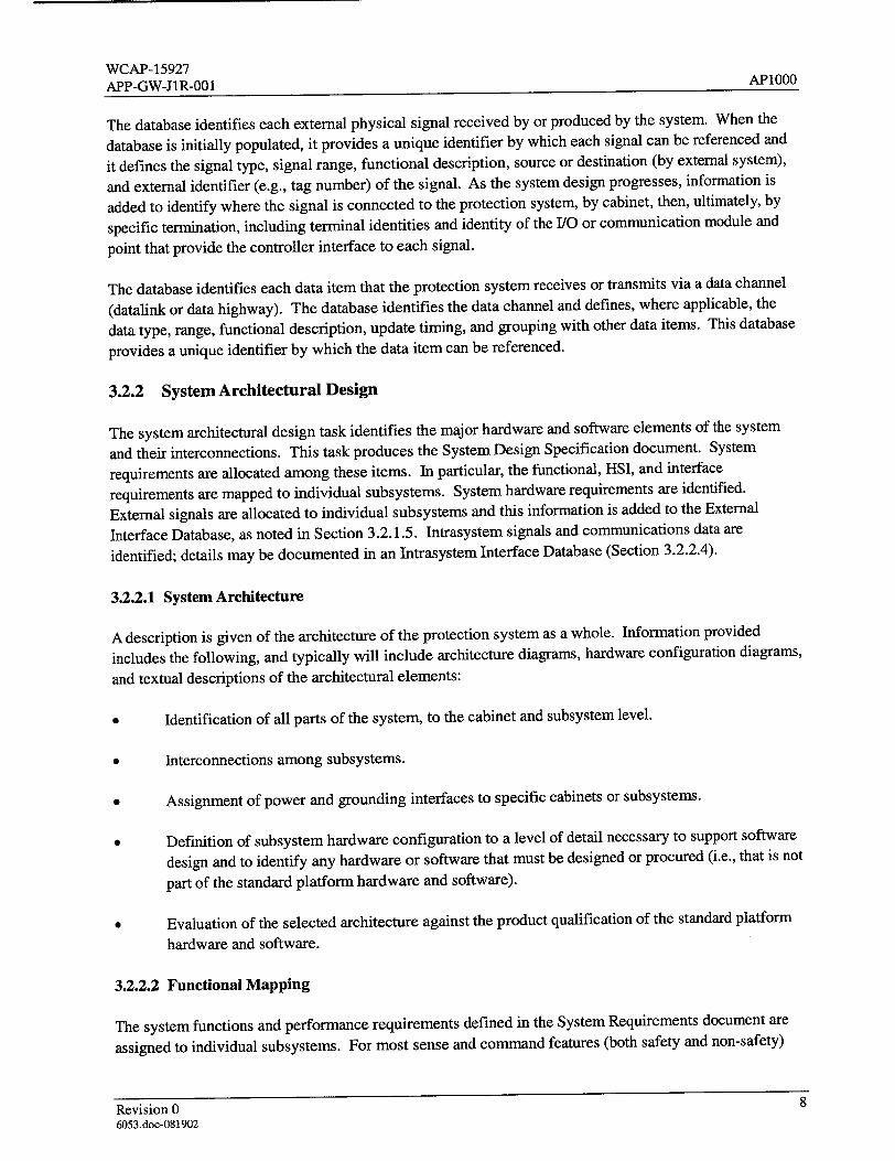
The database identifies each external physical signal received by or produced by the system. When the
database is initially populated, it provides a unique identifier by which each signal can be referenced and
it defines the signal type, signal range, functional description, source or destination (by external system),
and external identifier (e.g., tag number) of the signal. As the system design progresses, information is
added to identify where the signal is connected to the protection system, by cabinet, then, ultimately, by
specific termination, including terminal identities and identity of the I/O or communication module and
point that provide the controller interface to each signal.
The database identifies each data item that the protection system receives or transmits via a data channel
(datalink or data highway). The database identifies the data channel and defines, where applicable, the
data type, range, functional description, update timing, and grouping with other data items. This database
provides a unique identifier by which the data item can be referenced.
3.2.2 System Architectural Design
The system architectural design task identifies the major hardware and software elements of the system
and their interconnections. This task produces the System Design Specification document. System
requirements are allocated among these items. In particular, the functional, HSI, and interface
requirements are mapped to individual subsystems. System hardware requirements are identified.
External signals are allocated to individual subsystems and this information is added to the External
Interface Database, as noted in Section 3.2.1.5. Intrasystem signals and communications data are
identified; details may be documented in an Intrasystem Interface Database (Section 3.2.2.4).
3.2.2.1 System Architecture
A description is given of the architecture of the protection system as a whole. Information provided
includes the following, and typically will include architecture diagrams, hardware configuration diagrams,
and textual descriptions of the architectural elements:
* Identification of all parts of the system, to the cabinet and subsystem level.
0 Interconnections among subsystems.
* Assignment of power and grounding interfaces to specific cabinets or subsystems.
* Definition of subsystem hardware configuration to a level of detail necessary to support software
design and to identify any hardware or software that must be designed or procured (i.e., that is not
part of the standard platform hardware and software).
* Evaluation of the selected architecture against the product qualification of the standard platform
hardware and software.
3.2.2.2 Functional Mapping
The system functions and performance requirements defined in the System Requirements document are
assigned to individual subsystems. For most sense and command features (both safety and non-safety)
Revision 08 6053.doc-081902
WCAP-15927 APP-GW-J1R-001 AP1000
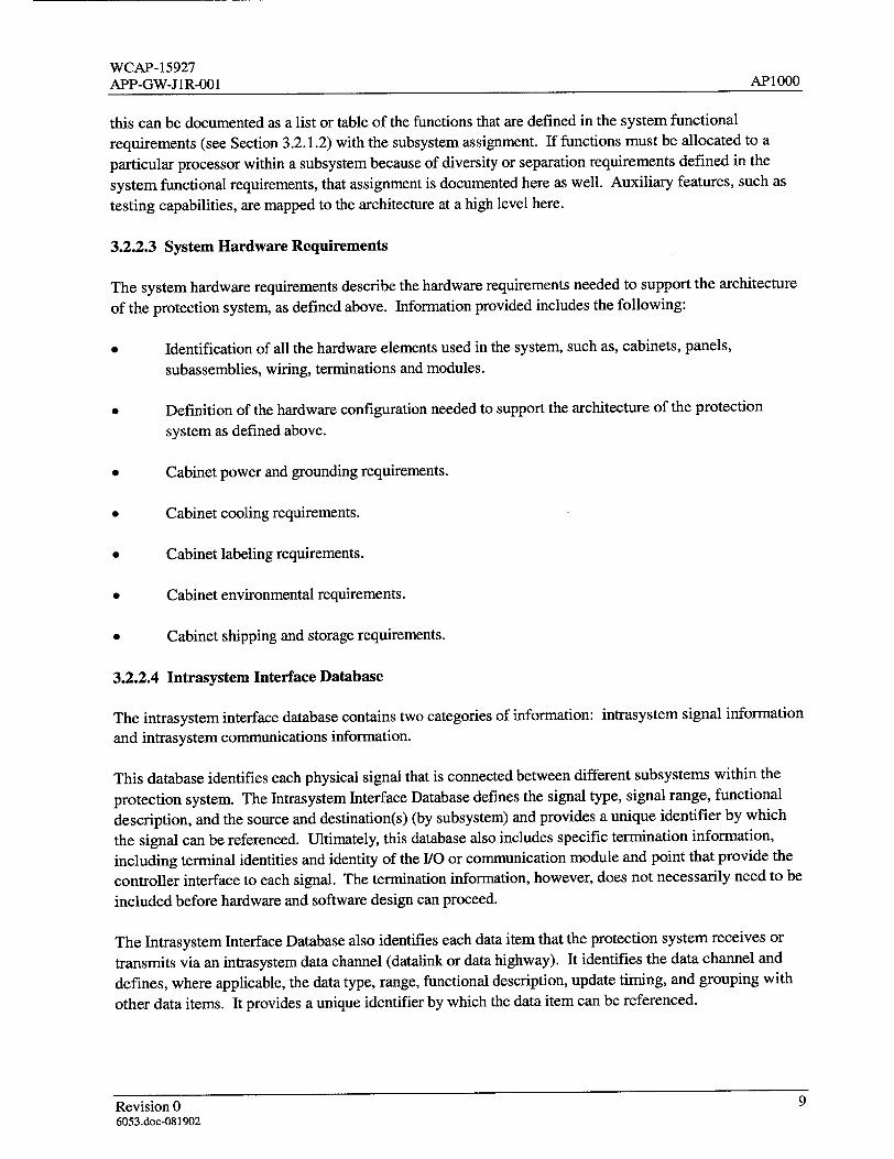
this can be documented as a list or table of the functions that are defined in the system functional
requirements (see Section 3.2.1.2) with the subsystem assignment. If functions must be allocated to a
particular processor within a subsystem because of diversity or separation requirements defined in the
system functional requirements, that assignment is documented here as well. Auxiliary features, such as
testing capabilities, are mapped to the architecture at a high level here.
3.2.2.3 System Hardware Requirements
The system hardware requirements describe the hardware requirements needed to support the architecture
of the protection system, as defined above. Information provided includes the following:
* Identification of all the hardware elements used in the system, such as, cabinets, panels,
subassemblies, wiring, terminations and modules.
0 Definition of the hardware configuration needed to support the architecture of the protection
system as defined above.
* Cabinet power and grounding requirements.
* Cabinet cooling requirements.
* Cabinet labeling requirements.
0 Cabinet environmental requirements.
* Cabinet shipping and storage requirements.
3.2.2.4 Intrasystem Interface Database
The intrasystem interface database contains two categories of information: intrasystem signal information
and intrasystem communications information.
This database identifies each physical signal that is connected between different subsystems within the
protection system. The Intrasystem Interface Database defines the signal type, signal range, functional
description, and the source and destination(s) (by subsystem) and provides a unique identifier by which
the signal can be referenced. Ultimately, this database also includes specific termination information,
including terminal identities and identity of the I/O or communication module and point that provide the
controller interface to each signal. The termination information, however, does not necessarily need to be
included before hardware and software design can proceed.
The Intrasystem Interface Database also identifies each data item that the protection system receives or
transmits via an intrasystem data channel (datalink or data highway). It identifies the data channel and
defines, where applicable, the data type, range, functional description, update timing, and grouping with
other data items. It provides a unique identifier by which the data item can be referenced.
Revision 09 6053.doc-081902
WCAP-15927 AP1000 APP-GW-JIR-001
3.2.3 Software Requirements Analysis
The software requirements analysis task completes the identification of the requirements for the software
in the system. The output of this task is a Software Requirements Specification (SRS) for the system
specific software. The requirements for the sense and command features typically will have been
documented by the functional mapping documented in the System Design Specification (see
Section 3.2.2.2). Any additional requirements will be identified in the SRS. The high-level requirements
for auxiliary features are refined into detailed requirements in the SRS. The SRS ensures that all
requirements are documented for the software in each subsystem. This information may be in the System
Requirements as they are mapped to subsystems and processors by the System Design Specification
(including information in the signal and communications databases). Additional information is
documented as detailed requirements in the SRS itself. Information in the software requirements analysis
includes:
Specific inputs and outputs, both those that are physical signals and information that is received from and
supplied to human users and external data systems.
Valid input ranges.
Output ranges, if they must be specifically limited.
Required HSI formats (e.g., input screen formats, printed report formats).
Required sequences of operations (e.g., test sequences, operator dialog sequences).
* Functional processing of the data.
* Timing requirements or constraints.
Response to abnormal conditions and error recovery.
Retention, use, and initialization of previous state information, where required.
Safety and security requirements.
Design constraints (e.g., the required use of a particular programming tool or language, or the
required use of particular platform software).
3.3 SOFTWARE DESIGN PHASE
In the software design phase, the software requirements are decomposed and allocated to individual
software components. The use of existing software components to implement the requirements is
described. New software components that must be created are identified. The software design is
described in Software Design Description (SDD) documents. A Preliminary Software Design Description
is produced in the software design phase and a Final Software Design Description is produced in the
software implementation phase. There is a Software Design Description for each processor module that
Revision 0 10
6053.doc-081902
WCAP-15927 AP1000 APP-GW-J I R-001
executes unique code. Redundant processors that execute identical, or nearly identical, code may have a
single SDD; this includes processors in separate divisions, if they have essentially identical code
(implement the same functions).
The Preliminary SDD contains the following categories of information:
Decomposition of the required functions into software entities (modules, procedures, type
circuits, etc.), including entity names and the reason for the existence of the entity.
Module timing and priority.
A description, where applicable, of how safety (sense and command) functions and auxiliary
functions are combined (e.g., the functionality required in bistable and logic processors to
implement periodic testing; local functionality required to support maintenance functions, such as
calibration data changes) In typical cases, this description may be made generic and included in
the "Design Constraints" section of the application SRS, or even in platform (non-project
specific) documentation; a reference to such generic information should be made where
applicable.
Identification of any generic type circuits or custom PC elements that need to be developed.
These may be project-universal elements (applicable in multiple (non-redundant) processors in
this specific project only) or they may be new platform software. In either case, their design and
implementation follows the platform software development process described in Sections 4.8,
4.9, and 4.10.
* Where applicable, handling of software initialization, redundancy, and tracking.
3.4 HARDWARE DESIGN PHASE
In the hardware design phase, the final construction configuration of the production hardware is specified.
The production unit specific Cabinet Assembly Drawings and Cabinet Configuration Drawings are issued
at this stage. These drawings contain all of the information necessary to produce the production unit
hardware. The drawings include the following information:
* Cabinet layout details * Cabinet assembly details 0 Cabinet bill of materials • Cabinet configuration details * Cabinet termination frame details * Cabinet internal wiring details
3.5 SOFTWARE IMPLEMENTATION PHASE
In the software implementation phase, the software items are created, typically by use of the
ABB/Advant® Master Programming Language (AMPL) tools. (Non-AC 160 subsystems require different
tools.) The application modules are integrated with platform software to produce code modules that are
Revision 0 11 6053 doc-081902
WCAP-15927 AP 1000 APP-GW-J 1R-001
downloaded into subsystem processors for verification and validation testing (described in the V&V
Plan). Descriptive information about the implementation is added to the preliminary SDD to produce the
Final SDD.
The following categories of information are added to produce the final SDD:
0 Mapping of signal names used in the code to names used in the requirements documents and
databases, where these differ.
• Traceability of the implementation to specific requirements (unless this information is included in
comments in the code).
* Printouts of the AMPL Function Chart diagrams.
• Any other non-obvious information that is needed to understand the software implementation and
its interfaces. The intention is that this is an aid to the individuals who will verify or maintain the
code. This should not repeat information that is clear to a knowledgeable individual reading the
diagrams (or non-AMPL source code listings).
3.6 HARDWARE IMPLEMENTATION (ASSEMBLY) PHASE
In this phase, the construction of the production unit hardware system is completed using the drawings
specified in Section 3.4.
3.7 SYSTEM INTEGRATION PHASE
In this phase, completed cabinets containing the applications software are connected together as a system.
Validation testing (described in the V&V Plan) is performed to test system functionality that was not
covered by the cabinet-level validation testing. System integration and testing may be done on
appropriate portions (e.g., individual divisions) of the system or on the complete system
3.8 INSTALLATION PHASE
The completed system is installed at the site. Site Acceptance Testing (SAT), described in the V&V Plan
is performed to assure that the system has not been damaged by shipping and installation. The SAT also
confirms proper operation of any interfaces that were not completely tested by the factory validation
testing, e.g., interfaces to other plant systems.
Revision 0 12
6053 doe-081902
WCAP-1 5927 API 000
WCAP-15927 AID-D_¢• 1- _ 1 RTIP- 1
PRODUCTSPHASE
Figure I Application Development Process
Revision 0 13
6053 doc-081902
Verification & Validation Method (Defined by V&V Plan)
[ Design Team - Review Venficabon Team - Requirements Traceability
{ Design Team - Review Venfication Team - Requirements Traceability
_ Design Team- Review
Verficatlion Team - Requirements Traceability
[ Design Team - Review
Design Tear. Venfication Team Common Element Sc(ftware Tests Processor Module Software Tests
Design Team - Review Venfication Team - Requirements Traceability
{ Design Team. Venfication Team (review) Cabinet Hardware Tests
{ Design Team. Venfication Team Cabinet Integration Tests System Integration Test
' Installation Team Site Acceptance Test (SAT)
•l ,It -"J vv-
APIO000
WCAP-15927 AP1000
APP-GW-J IR-001
IEC, IEEE 12207
Development Process Activities
Software Program Manual
Life Cycle Phases
Safety System Design Process Application
Development Phases
Management
Process Conceptual
PoetConcept (Pro!ec Project
(Initiation) Definition)
=Management < rcs ý liibn
Process Implementation
Software •Software
Architectural •Design Design
Design Design I
Software D Hardware
Detailed Design
Figure 2 Correlation to Standard Life Cycle Phases
Revision 0 14
6053.doc-081902
IEEE 1074 Life Cycle Processes
WCAP-15927 AP 1000 APP-GW-J 1R-001
4 PLATFORM DEVELOPMENT
This section defines the Common Q platform development process. The objective of the platform
development process is the creation of a general safety system platform that is suitable for use in multiple
nuclear plant applications, including APIOO1. The platform requirements are not formally traceable to
specific plant fuxictional requirements, but are created based upon industry standards, regulatory
requirements, and engineering experience in and knowledge of the types of functions that are required for
typical safety system applications. The Westinghouse safety system platform is the Common Q platform.
The Common Q platform consists primarily of the ABB AC160 hardware and software product line,
including the Advant® development tools. The AC160 product line is not developed by Westinghouse. It
is developed commercially. It was selected and qualified by Westinghouse for use in Common Q
applications by a process of commercial dedication.
The Common Q platform also contains certain products that are not ABB Advant® commercial
components. These include software and hardware elements that are developed by Westinghouse,
specifically for the Common Q platform. Some of these products may contain a mixture of both
commercially dedicated products and software and hardware elements developed by Westinghouse.
This section describes the design and selection process for both the commercial dedication portions on the
Common Q platform and the portions on the Common Q platform that are developed by Westinghouse.
The details of the commercial dedication program used for the ABB AC160 hardware and software
product line qualification are not covered here. The commercial dedication program is defined in
CENPD-396-P, "Common Qualified Platform Topical Report" (Reference 5.2.2).
The relationship of software and system verification and validation (including testing) to this
development process is shown, but the details are defined by the Verification and Validation (V&V) Plan.
The Life Cycle phases of the platform development are:
0 Conceptual * Platform Requirements Analysis a Product Selection * Platform System Architectural Design * Hardware Requirements Analysis * Hardware Design • Hardware Implementation • Software Requirements Analysis * Software Design * Software Implementation
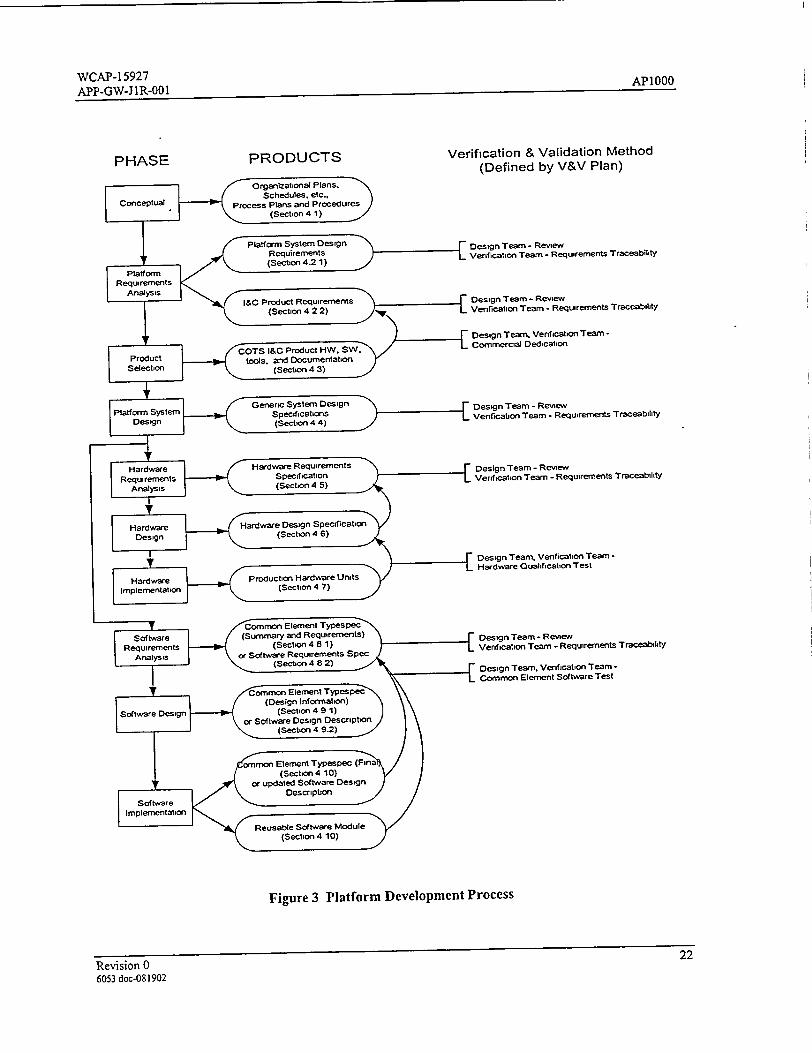
Figure 3 illustrates the relationship of the platform development phases to each other and to the V&V
process. It also shows the outputs of each phase. The activities and products of these phases are
described in the remainder of this section. The flow of activities shown in Figure 3 is similar to that of a
classic "waterfall" development process. It is intended, however, that these activities may be both
Revision 0 15
6053 doc-081902
WCAP-15927 AP1000 APP-GW-J IR-001
iterative and overlapping. Work may commence on a given development phase before preceding phases
are complete.
Testing activities also are defined as part of the V&V process. The testing activities complement the
Implementation phase. System integration and installation phases are not defined for the generic platform
development. Although a prototype system may be created to facilitate testing of platform hardware and
software, such a system is not an end product of the platform development process.
4.1 CONCEPTUAL PHASE
The conceptual phase is a preparatory phase before the platform safety system design begins. The major
tasks of this phase are setting up the department organization and the department policies and procedures.
The discussion of the details of this phase is outside the scope of this document.
4.2 PLATFORM REQUIREMENTS ANALYSIS PHASE
The main tasks in the platform definition phase are to identify the applicable platform requirements, and
to define the criteria (hardware and software critical characteristics) for the selection and qualification of
the Commercial Off-the-Shelf (COTS) I&C product line that will form the basis of the safety system
platform. The outputs of this phase are a Platform System Design Requirements document and an I&C
Product Requirements document.
4.2.1 Platform System Design Requirements
This information provides the design basis for the safety system product line. It contains the following
categories of requirements for the product line hardware and software as well as for systems built from
the product line.
0 Applicability of codes and standards, either in whole, or in part, or as guidance.
a General design requirements: design basis, single failure criteria, integrity, independence,
maintenance, manual capabilities, information display, access control, identification, calibration
capabilities, reliability, and availability.
* Hardware qualification: environmental, EMC, and seismic.
° Power and grounding.
0 External interface capabilities.
0 Performance requirements, time response, accuracy, and signal noise.
* Human-System Interface (HSI) capabilities.
0 Test and diagnostic capabilities.
Revision 0 16
6053 doc-0S1902
WCAP-15927 AP1OQO APP-GW-JIR-001
* Development tools.
* Design constraints and objectives.
* Intended applications.
4.2.2 I&C Product Requirements
This document identifies the functional, architectural, and performance requirements for the use of a
COTS I&C control product line (programmable controller) in safety system applications.
4.3 PRODUCT SELECTION PHASE
In this phase, a COTS I&C product line is selected and qualified. The output of this phase is an identified
set of hardware, software, development tools, and associated vendor documentation. The qualification
activity will also produce a qualification report that identifies any constraints on the use of the product
line for safety applications.
4.4 PLATFORM SYSTEM ARCHITECTURAL DESIGN PHASE
This phase defines the representative system architectures for the typical applications of the platform.
These provide a basis to identify needed platform hardware and software elements that are not provided
by the qualified COTS product line. They also are standard system designs that will be used as the basis
for specific applied systems. The outputs of this phase are Generic System Design Specifications for each
of the types of applications intended to be implemented with the safety system platform (e.g., Plant
Protection System, Post Accident Monitoring System, Core Protection Calculator).
Information provided in the generic design specification includes the following:
* Identification of all parts of the system, to the cabinet and subsystem level.
* Definition of subsystem hardware configuration to a level of detail necessary to support hardware
and software selection or design.
* Identification of hardware and software functionality needed to support the architecture,
configuration, and typical functionality (including typical sense and command functions, both
safety and non-safety, as well as auxiliary functions, such as maintenance and test).
0 Typical interconnections among subsystems.
0 Assignment of types of external signals to subsystems.
* Assignment of typical system functionality to specific subsystems.
• Assignment of typical functionality to hardware or software.
Revision 0 17
6053 doe-081902
WCAP-15927 AP1000 APP-GW-J 1R-001
Architecture diagrams.
* Hardware configuration diagrams.
4.5 HARDWARE REQUIREMENTS ANALYSIS PHASE
This phase defines the requirements for hardware elements that are designed specifically for the platform
(as opposed to pre-existing commercially available modules). The output of this phase is a Hardware
Requirements Specification for each hardware element being designed.
The Hardware Requirements Specification includes the following types of information:
9 Performance requirements * Reliability goal * Mechanical requirements • Electrical requirements • Packaging requirements
• Environmental requirements
• EMC requirements * External interface requirements
• Seismic requirements • Storage requirements
• Shipping requirements
4.6 HARDWARE DESIGN PHASE
This phase provides the design details for hardware elements that are designed specifically for the product
line (as opposed to pre-existing commercially available modules). The output of this phase is a Hardware
Design Specification for each hardware element being designed.
The Hardware Design Specification consists of all of the information necessary to produce the hardware
element, including the necessary drawings. It includes the following types of information:
• Description • Mechanical design • Performance specifications * Application * Operation • Testing * Calibration • Environmental * Reliability
The drawing package includes the following information:
* Bill of materials
• Assembly drawing
Revision 0 18
6053 doc-081902
WCAP-15927 AP1000 APP-GW-J1R-001
* Printed circuit artwork, drill plan, and solder mask
* Schematic * Note sheet * All mechanical detail & assembly drawings
4.7 HARDWARE IMPLEMENTATION PHASE
In this phase, the production hardware unit is manufactured.
4.8 SOFTWARE REQUIREMENTS ANALYSIS
This phase defines the requirements for software elements that are designed specifically for the platform
(as opposed to pre-existing commercially available software). The output of this phase depends upon the
nature of the software elements being specified. Reusable common software elements can be created for
the Advant® AC 160 product line in the form of Type Circuits, Functional Units, and Custom PC
Elements. A Type Circuit or a Functional Unitt1P is a prearranged group of the smaller pre-existing
commercially available software units (PC Elements) into a larger, more complex software entity. Type
circuits and functional units are not compiled code, but more like AMPL macro definitions that can be
saved individually and reused throughout one or more projects. Custom PC Elements are compiled from
source code and added to the library of standard PC elements available for AMPL programming.
Common software elements that are type circuits, functional units, or general purpose custom PC
elements (new PC elements intended for common use in many different safety applications) are
documented with a composite document referred to as a Typespec. A common element Typespec
combines requirements, design description, and user information into a single document. Special purpose
custom PC elements (e.g., those developed for the core protection calculator) and also non-AMPL type
platform software (e.g., custom software for the flat panel display units) are documented in Software
Requirements Specification documents and Software Design Description documents.
4.8.1 TypeSpec (Summary and Requirements)
The portion of a Typespec that contains the product of the Software Requirements Analysis contains the
following categories of information:
* An element (type circuit, functional unit, custom PC element) summary consisting of a general
functional description of the element.
0 Requirements Specification:
- Functional requirements (functions implemented, timing, accuracy)
- Input/Output terminal descriptions (default values, data types, data ranges)
- Overflow/ error handling (range checking, failure modes, alarming)
- Truth Table (outputs as a function of input combinations)
) A Functional Unit is a way of packaging a Type Circuit for more flexible use by the Advant Engineering
Database tool
Revision 0 19
6053 doc-081902
WCAP-1 5927 AP1000 APP-GW-J IR-001
4.8.2 Software Requirements Specification
For more complex software, the following categories of information are documented in a Software
Requirements Specification:
0 Software structure * Software technical description * Interfaces 0 Auxiliary function items • Usage constraints 0 Configuration data • Error handling • Performance requirements • Software safety requirements
4.9 SOFTWARE DESIGN PHASE
This phase establishes the design of software elements that are designed specifically for the platform (as
opposed to pre-existing commercially available software). As stated in Section 4.8, the output of this
phase depends upon the nature of the software elements being specified. The design information for non
complex common platform elements is added to the Typespec, whereas the design of complex software
modules is described in a Software Design Description.
4.9.1 TypeSpec (Design information)
The portion of a Typespec that contains the product of the Software Design Phase contains any design
information that is not obvious from the implementation (AMPL diagram or code comments).
4.9.2 Software Design Description
For more complex software, the following categories of information are documented in a Software
Design Description (SDD):
0 Description of safety functions * Description of auxiliary functions * Decomposed of function 0 Software architecture * Module decomposition • Module timing and priority * Data flow diagrams
The level of detail should be only what is necessary to understand the design, given the requirements
specification and the commented source code.
Revision 0 20
6053 doc-081902
WCAP-15927 AP 1000 APP-GW-J 1R-001
4.10 SOFTWARE IMPLEMENTATION PHASE
In this phase, the software items are created. The software elements are integrated with other product
software and with test applications code to support V&V testing. The output of this phase, however, is
the new platform software element in the form necessary to be placed under configuration control and
made available for reuse (e.g., AMPL type circuit files or source and compiled object code). In the case
of the non-complex common elements, an additional output is the final version of the Typespec. For
complex software modules the SDD is updated with any information that is necessary to understand the
code implementation.
The implementation description (printout of the AMPL diagram) is added to the Typespec and a User's
Guide section is added (giving the information that a developer needs to know to incorporate the common
element into an application program). The complete Typespec then contains the following information:
* The element summary (as described in Section 4.8.1)
0 The requirements specification (as described in Section 4.8.1)
• Design information (as described in Section 4.9.1)
0 Implementation (print-out of AMPL diagram for the "Type Circuits")
* Users Guide:
- Detailed instantiation procedure (prerequisites, applicability, restrictions, signal
connections)
- Configuration/Applications (Database elements connections, 1/0 interfaces, High Speed
Datalink (HSL) interfaces, AF100 interfaces, default values used.)
Revision 0 21
6053 doc-081902
WCAP-15927 AP1000 APP-GW-J IR-001
PRODUCTSVerification & Validation Method
(Defined by V&V Plan)
Design Team - Review Verification Team - Requirements Traceability
"Design Team. Venfication Team Commercial Dedication
Design Team - Review Verification Team - Requirements Traceability
Design Team - Review
Verification Team - Requirements Traceability
IDesign Team. Verification Team Hardware Qualificatiofn Test
E Design Team - Review
Verification Team - Requirements Traceability
Figure 3 Platform Development Process
Revision 0 22
6053 doc-081902
PHASE
WCAP-15927 APP-GW-JIR-001 AP1000
5 REFERENCES
5.1 INDUSTRY STANDARDS AND CODES
5.1.1 IEEE Std. 1074-1995, "IEEE Standard for Developing Life Cycle Processes."
5.1.2 IEEE/EIA 12207.0-1996, "Industry Implementation of International Standard ISO/IEC 12207:
1995 (ISO/IEC 12207) Standard for Information Technology-Software Life Cycle Processes."
5.2 WESTINGHOUSE DOCUMENTS
5.2.1 CE-CES-195, "Software Program Manual for Common Q Systems."
5.2.2 CENPD-396-P, "Common Qualified Platform Topical Report."
Revision 0 6053 doc-081902
.4.')
Top Related