
![Engineering Mathematics I - Rami Zakaria Mathematics I_ 2017 ... Ref [1] Advanced Engineering Mathematics, 4th ed., by Dennis G. Zill & Warren S. Wright . Part 1:](https://static.fdocuments.in/doc/165x107/5b0cdaaf7f8b9a2c3b8c4679/engineering-mathematics-i-rami-mathematics-i-2017-ref-1-advanced-engineering.jpg)


Languages
Pages
Legal


Fire Protection AnalysisWarren J. Baker Center for Science and Mathematics
San Luis Obispo, California
Prepared and presented by Blake JohnsonWinter Quarter 2015

Overview• Project Building Information• Prescriptive Analysis
– Structural Fire Protection Analysis
– Egress Analysis– Fire Suppression System
Analysis– Fire Alarm and Detection
System Analysis
• Performance-Based Analysis– Fire Scenario Selection– Atrium Analysis

Project Building Information• Warren J. Baker Center for Science and Mathematics • Building 180 on Cal Poly SLO campus• 6-story, ~189,000 ft2 area, with lecture halls, labs,
offices, study spaces• Accommodates ~1650 students in classrooms and labs

Project Building Information
• Type I-B construction• Occupancy primarily
B, some A, H, and S• Total occupant load
of 2906 persons• 108 ft height,
non-high-rise• Fully sprinklered• 5-story atrium
Structural Fire Protection Analysis
•Structural Summary•Fire Resistance Requirements
•Structural Fire Protection(IBC)

Structural Summary
• Steel frame construction– W-section beams, girders, and columns– Moment frame– Metal deck with LW concrete fill– HSS used in vertical shafts
• 16" thick reinforced concrete retaining walls on levels 1 and 2

Fire Resistance Requirements• Fire resistance ratings
(Table 601)– Members supporting roof
only use lower rating– S-1 roof must be 1-hour– Separation distance over
30 ft (Table 602 not used)• Separation of occupancies
(Table 508.4)– B and all, except itself and
S-1, by 1-hour– S-1 and S-2 by 1-hour– S-2 and H-3 by 1-hour
Structural Element Hourly RatingStructural Frame 2 or 1
Bearing walls
Exterior 2Interior 2 or 1
Non-bearing walls 0Floor 2Roof 0 or 1
Hourly Separation of Occupancies
S-1 S-2 H-3B 0 1 1
S-1 - 1 -S-2 - - 1

Structural Fire Protection• W-shapes fireproofed with SFRM
– W-shaped girders and beams fireproofed to UL Design No. 917– W-shaped columns fireproofed to UL Design No. X772– SFRM boxed with steel channels and gypsum wallboard– SFRM thickness listed in UL Design No.
• Floor deck rating from IBC (Table 721.2.2.1 and 721.2.2.1.3)– Effective slab thickness calculated to be 3.75"– Required thickness for LW concrete of 3.6" met for 2-hour rating
• RC retaining walls on levels 1 and 2 are well beyond the required 5" (Table 721.1(2)) to meet a 2-hour fire rating

Egress Analysis
•Occupancy•Means of Egress
•Fire Rating•Tenability
(LSC)

Occupancy• Mixed occupancy
(6.1.14.2.2)• A-3 most restrictive• Plans IBC, but meet
LSC with minor discrepancies
• Occupants are adult students and professors who are awake and alert
• Occupancy maps on following slides
Group Level Use
B AllAtrium, Classrooms, Labs, Offices, Workspaces, others
A-3 1, 3, 4, 5, 6
Lecture Halls, Terraces
H-3 2 HazardousS All StorageS-1 All MechanicalS-2 1 Electrical

Means of Egress
• Capacity designed with IBC load factors!– Stair 0.2 vs. 0.3 LSC– Door 0.15 vs. 0.2 LSC
• Still meets LSC
Level ComponentLoad
(persons)Factor
(in/person)Width (in) Meets
Required?Required Provided
1 Door Main 352 0.2 71 216 Yes
1 Door Back 352 0.2 71 96 Yes
1 Door 4 160 0.2 32 36 Yes

Means of Egress• Number of exits OK
(7.5.1.3)• Common path of
travel, dead end, and travel distances OK
LSC Section and Distance Assembly Business Storage
Common Path
12.2.5.1.2 20 or 75* ft
38.2.5.3.1 100 ft
42.2.5 100 ft
Dead End 12.2.5.1.3 20 ft
38.2.5.2 50 ft
42.2.5 100 ft
Travel Distance
12.2.6.2(1) 250 ft
38.2.6.3 300 ft
42.2.6 400 ft

Means of Egress• Exit signage OK, but
could be reduced with 7.10
• Estimated total evacuation time calculated using NFPA Fire Protection Handbook Chapter 4-2– Queuing assumed– Travel speed down
stairs:105 ft/min– Travel speed through
atrium (Stair 3): 235 ft/min

Means of Egress
• Estimated total evacuation time is about 13 minutes
• Pre-movement (delay) time not accounted for in calculation
– Delay time can be estimated from SFPE Handbook Table 3-12.2
– Consider as mid-rise office building (warm day) – delay time average 36 seconds
• Total evacuation time about 13.5 minutes
Stair # 1 3 4 5
Limiting Component Stair Door Door Stair
Flow (persons/min) 59.35 48 48 59.35
Total Load (persons) 413 573 389 234
Travel Time (min) 0.48 0.74 0.48 0.48
Total Time (min) 7.4 12.7 8.6 4.4

Fire Rating• Stair enclosures (7.1.3.2.1)
and interior finish (__.3.3)• Interior finish reduced by one
step (10.2.8)– Controlled by Assembly– Stairways Class A or B– Elsewhere Class A, B, or C– Floor Class I or II or meets
10.2.7.2
Stair #
LevelTotal
Fire Resistance Rating
1 2 3 4 5 6 Required Provided
1 x x x 3 1-hour 2-hour
3 x x x x x 5 2-hour 2-hour
4 x x x x 4 2-hour 2-hour
5 x x 2 1-hour 2-hour

Tenability• Any occupant not intimate
with ignition shall not be exposed to untenable conditions (5.2.2)
• Smoke/visibility controls tenability
• Based on fire scenarios• Especially important in
atrium

Fire Suppression System Analysis•Occupancy
•Water Supply•Fire Suppression System
(NFPA 13)
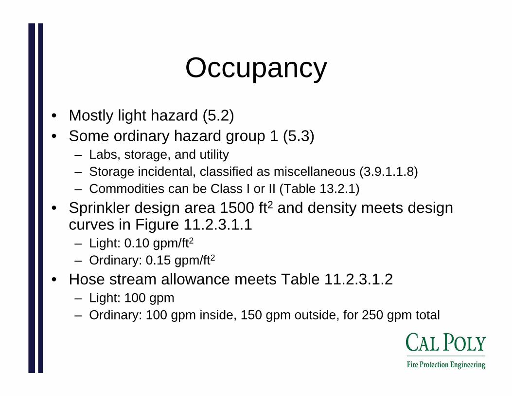
Occupancy• Mostly light hazard (5.2)• Some ordinary hazard group 1 (5.3)
– Labs, storage, and utility– Storage incidental, classified as miscellaneous (3.9.1.1.8)– Commodities can be Class I or II (Table 13.2.1)
• Sprinkler design area 1500 ft2 and density meets design curves in Figure 11.2.3.1.1– Light: 0.10 gpm/ft2– Ordinary: 0.15 gpm/ft2
• Hose stream allowance meets Table 11.2.3.1.2– Light: 100 gpm– Ordinary: 100 gpm inside, 150 gpm outside, for 250 gpm total

Water Supply• Water supply is city water
– Static pressure: 60 psi– Residual pressure: 55 psi– Flow rate: 914 gpm
• Highest pressure demand at base of riser is 168 psi
• Adequate flow, poor pressure – pump required
• Fire pump in-line, rated at 750 gpm, 113 psi, 58.1 HP, efficiency 85.3%

Fire Suppression System• Wet pipe system (7.1)• Most pipes concealed• Standpipes and riser
concealed in stairways• Sprinklers mostly pendant
type, some upright type– Quick response– K-factor 5.6
• System supported by TOLCO seismic braces
Stair # Type Pipe Size
1 Standpipe 6” Schedule 10
3 Riser 6” Schedule 10
4 Standpipe 4” Schedule 10
5 Standpipe 4” Schedule 10
- Cross mains 2½” to 3” Schedule 10
- Branch lines 1” to 1¼” Schedule 10
Seismic design category D
Soil profile Type B
Spectral response accelerations
Ss 1.26
S1 0.481
Seismic coefficient Cp 0.61
Fire Alarm and Detection System Analysis
•Fire Alarm System•Fire Detection System
(NFPA 72)

Fire Alarm System
• Fire alarm with in-building fire emergency voice alarm communication system (EVACS)
• No mass notification system (MNS)• Fire alarm control panel (FACP) located in main
electrical/transformer room (room122) on level 1• FACP is Honeywell Notifier, model # NFS2-640• Fire alarm terminal cabinets (FATC) on levels 2,
3, 4, and 5 located in utility spaces
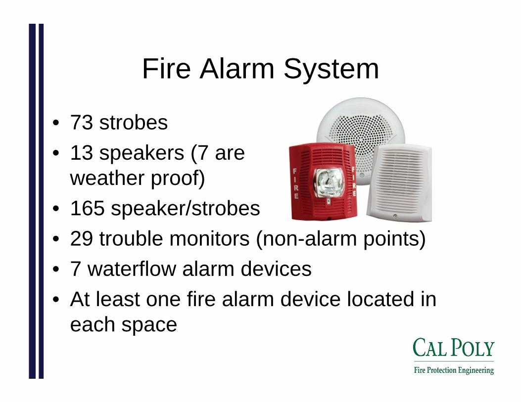
Fire Alarm System
• 73 strobes• 13 speakers (7 are
weather proof)• 165 speaker/strobes• 29 trouble monitors (non-alarm points)• 7 waterflow alarm devices• At least one fire alarm device located in
each space
Fire Alarm System• Audible devices must have a sound level at least 15 dB
above the average ambient sound level (18.4.3)– Average ambient sound level is 55 dBA– Minimum speaker sound level is 70 dBA
• Device sound level in dBA determined from wattage and model number given on plans– Horns meet 70 dBA after 40' of sound loss– All points in every space within 40' of a horn so audible
requirements met• Candela ratings for strobes given on plans
– Candela ratings adequate to cover area (Table 18.5.5.4.1(a)) of all rooms
– Visible signaling requirements (18.5) met for all rooms

Fire Alarm System
• EVACS (24.4.2)– 1 voice alarm channel– 172 speakers– 9 speaker circuits
• Amplification and sound-processing equipment located at FATC locations
• Paging microphone station is at the fire alarm control unit (FACU) in room 122 (24.4.2.5)

Fire Detection System
• Requirements NFPA 72, placements IBC• Smoke detection system (17.7)
– Photoelectric smoke detectors (17.7.3.2)– Photoelectric duct detectors (17.7.5)– Beam smoke detectors (17.7.3.7)
• Manual pull stations (IBC 907.4.2)• Sprinklers

Fire Scenario Selection
•Fire Risk•Example Scenario

Fire Risk• LSC 5.5.3.6 – Design fire scenario 1• Probabilistic approach based on statistical data of buildings with
similar uses• NFPA report “Structure Fire in Educational Properties” (Richard
Campbell, 2013)– 700 fires involving college classroom buildings and adult education
centers per year– Data from 2007-2011
Cause Fires (%) Damage (%)Cooking equipment 51 2
Intentional 10 10
Heating equipment 8 8
Smoking materials 5 0
Electrical distribution & lighting equipment 5 18
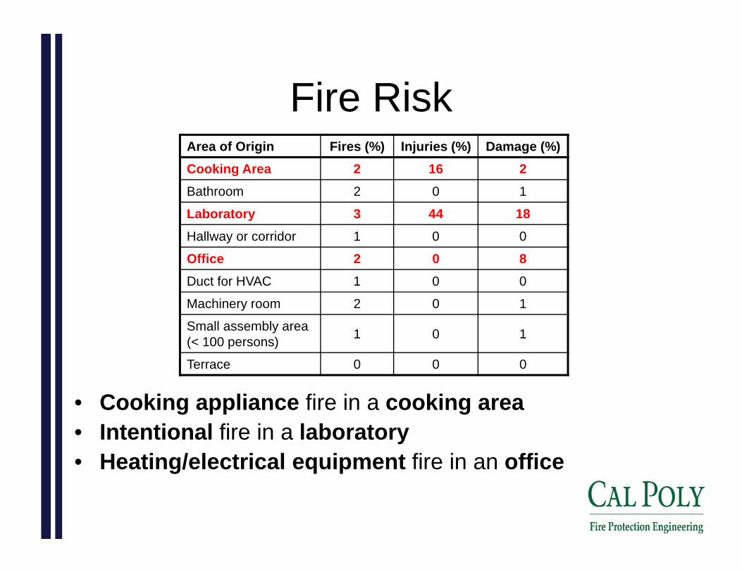
Fire RiskArea of Origin Fires (%) Injuries (%) Damage (%)Cooking Area 2 16 2Bathroom 2 0 1
Laboratory 3 44 18Hallway or corridor 1 0 0
Office 2 0 8Duct for HVAC 1 0 0
Machinery room 2 0 1
Small assembly area (< 100 persons) 1 0 1
Terrace 0 0 0
• Cooking appliance fire in a cooking area• Intentional fire in a laboratory• Heating/electrical equipment fire in an office

Example Scenario
• Intentional laboratory fire– Fuel: Flammable
laboratory chemicals– Cause: Experiment gone
awry• t-squared ultrafast fire
t-squared Ultrafast Fire
0
500
1000
1500
2000
2500
3000
0 15 30 45 60 75 90 105 120
Time (s)
HRR
(kW
)

DETACT
0
50
100
150
200
250
300
0 15 30 45 60 75 90 105 120 135Time (s)
Tem
pera
ture
(°C
)
0
500
1000
1500
2000
2500
3000
3500
4000
4500
5000
HR
R (k
W)
Gas temp Det. temp HRR
Example Scenario• DETACT model can be used
– No smoke detectors, sprinklers only– Spaced at 10 ft, ceiling height 10' 6"– Activation temperature 68.3 °C – RTI 266 m1/2s1/2
• Activation time is 115 seconds, at an HRR of 2500 kW

Atrium Analysis
•Atrium Information•Tenability•CFAST
•FDS

Atrium Information• 5-story atrium on levels 2 to 6• Connects East and West
wings of building• Offices connect to atrium
– Through lobbies on levels 2 and 3
– Directly on levels 4, 5, and 6
• Convenience stairway not part of the primary means of egress
• Stair 3 exit access and discharge passing through atrium allowed (LSC 8.6.7(2))
• Offices directly connected must be protected by a 1-hour fire barrier OR engineering analysis required (LSC 8.6.7)– NOT protected by a 1-hour fire
barrier– Engineering analysis must be
performed to meet LSC!
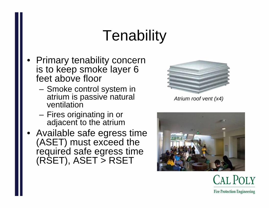
Tenability• Primary tenability concern
is to keep smoke layer 6 feet above floor– Smoke control system in
atrium is passive natural ventilation
– Fires originating in or adjacent to the atrium
• Available safe egress time (ASET) must exceed the required safe egress time (RSET), ASET > RSET
Atrium roof vent (x4)
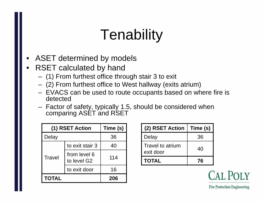
Tenability• ASET determined by models• RSET calculated by hand
– (1) From furthest office through stair 3 to exit– (2) From furthest office to West hallway (exits atrium)– EVACS can be used to route occupants based on where fire is
detected– Factor of safety, typically 1.5, should be considered when
comparing ASET and RSET
(1) RSET Action Time (s)Delay 36
Travel
to exit stair 3 40from level 6 to level G2 114
to exit door 16TOTAL 206
(2) RSET Action Time (s)Delay 36Travel to atrium exit door 40
TOTAL 76

CFAST• Compartments based on area for each floor, East and
West hallways, and floor-to-floor, vertical openings• Smoke detectors positioned at zones between floors
– Positioned to represent beam detectors– Smoke-temperature correlation (13 °C rise) as detection basis
• Natural ventilation– East/West hallway doors initially open and automatically close at
time when fire detected– Ground level doors initially closed and automatically open at time
when fire detected• Two fire scenarios
– Office fire adjacent to atrium that spills smoke into the atrium– Upholstered chair fire in atrium
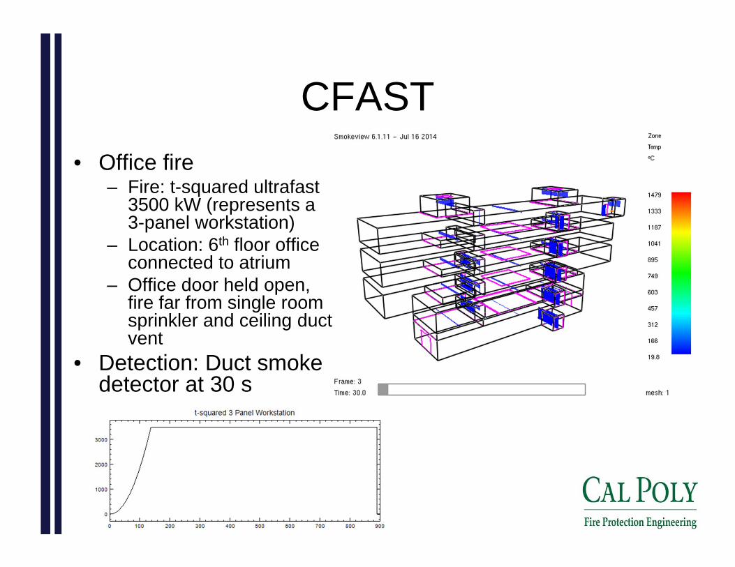
CFAST• Office fire
– Fire: t-squared ultrafast 3500 kW (represents a 3-panel workstation)
– Location: 6th floor office connected to atrium
– Office door held open, fire far from single room sprinkler and ceiling duct vent
• Detection: Duct smoke detector at 30 s

CFAST
• ASET > RSET for all levels: design criterion met• ASET > 1.5 * RSET for levels 5 and 6
– Margin of safety not met– EVACS should inform atrium occupants on levels 5
and 6 to use alternative exits at East/West ends of building
LevelSmoke Layer
Height at Detection (ft)
Time at Tenability Failure (s)
ASET (s)
RSET (1) (s)
ASET RSET
(1)
RSET (2) (s)
ASET RSET
(2)G2 11.3 260 230 52 4.42 52 4.423 10.3 180 150 121 1.90 76 1.974 10.6 320 290 149 1.54 76 3.825 10.5 370 340 178 1.29 76 4.476 10.5 600+ 570+ 206 1.12 76 7.5+

CFAST• Upholstered chair
fire, cotton fabric– Fire: t-squared
medium 700 kW – Location: 1st floor
center of atrium at wall
• Detection: Beam smoke detector at 130 s
CFAST
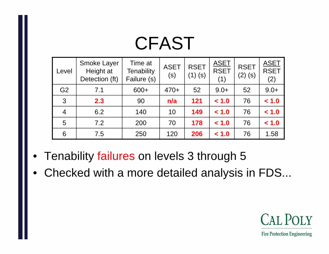
• Tenability failures on levels 3 through 5• Checked with a more detailed analysis in FDS...
LevelSmoke Layer
Height at Detection (ft)
Time at Tenability Failure (s)
ASET (s)
RSET (1) (s)
ASET RSET
(1)
RSET (2) (s)
ASET RSET
(2)G2 7.1 600+ 470+ 52 9.0+ 52 9.0+3 2.3 90 n/a 121 < 1.0 76 < 1.04 6.2 140 10 149 < 1.0 76 < 1.05 7.2 200 70 178 < 1.0 76 < 1.06 7.5 250 120 206 < 1.0 76 1.58

FDS
• Same simplified geometry as CFAST• Detection: Smoke detector at 85 s
700 kW Medium t-squared Cotton Fabric Chair Fire
0
100
200
300
400
500
600
700
800
900
1000
0 60 120 180 240 300 360 420 480 540 600
Time (s)He
at R
elea
se R
ate
(kW
)
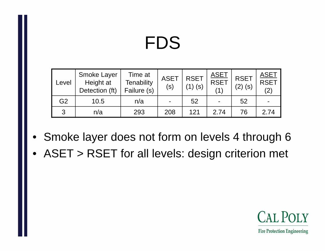
FDS
• Smoke layer does not form on levels 4 through 6• ASET > RSET for all levels: design criterion met
LevelSmoke Layer
Height at Detection (ft)
Time at Tenability Failure (s)
ASET (s)
RSET (1) (s)
ASET RSET
(1)
RSET (2) (s)
ASET RSET
(2)G2 10.5 n/a - 52 - 52 -3 n/a 293 208 121 2.74 76 2.74

FDS
• At level 3 tenability failure

THANK YOU!
Questions?
Top Related