


Languages
Pages
Legal


www.wardmfg.com (800) 248-1027
Ward Manufacturing PiPe fittings catalog

Ward’s mission is profitable growth
by exceeding customer expectations through innovation, quality and commitment.

TABLE OF CONTENTS
SECTION 1Standard Malleable Fittings Class 150.................................................................................................................................................. Pgs. 6 – 16
SECTION 2Extra Heavy Malleable Fittings Class 300............................................................................................................................................. Pgs. 17 – 22
SECTION 3Quality Pipe UnionsClass 150, Class 250, Class 300, Brass-to-Brass.................................................................................................................................. Pgs. 23 – 27
SECTION 4Plugs & Bushings.................................................................................................................................................................................... Pgs. 28 – 36
SECTION 5Top Beam Clamps & “C” Clamps........................................................................................................................................................... Pgs. 37 – 38
SECTION 6Standard Cast Iron Pipe Fittings Class 125, Class 250........................................................................................................................ Pgs. 39 – 52
SECTION 7Flanges, Flange UnionsCompanion Flanges, Flanged Fittings................................................................................................................................................... Pgs. 53 – 68
SECTION 8Cast Iron Drainage Fittings.................................................................................................................................................................... Pgs. 69 – 75
SECTION 9Wardlox™ Fittings..................................................................................................................................................................................... Pgs. 76 – 79
SECTION 10Teelox™ Fittings........................................................................................................................................................................................ Pg. 80
SECTION 11 Standard Merchant Couplings................................................................................................................................................................ Pg. 81
4

THE WARD STORY
Ward Manufacturing, LLC was founded in Blossburg, PA by Mr. Joseph P. Ward in 1924.
Beginning in a modest fashion with approximately thirty employees, a small line of cast iron steam and drainage fittings were manufactured along with cast iron plugs and bushings.
In the following four years a rapidly increasing demand for Ward products was experienced. Accordingly, in 1928, the manufacturing facilities were doubled in size and cast iron steam fittings and the drainage fittings product lines were expanded to include 4 NPS. At the same time class 150 malleable fittings were introduced in sizes ranging from 1/8 through 4 NPS.
During the next decade Ward continued to grow in size and stature and became an increasingly important factor in the American pipe fittings industry.
Further expansion was completed in 1938 with the addition of a facility to produce malleable iron pipe unions. These products were an immediate success and assumed a prominent position in Ward’s product offering.
Continued growth and the ever increasing demand for competitively priced products called for higher volume and more efficient molding facilities. To satisfy this business pressure, a totally new and highly automated foundry was erected in 1955 and, to this day, through careful maintenance, continuous improvement and reinvestment, this facility is equipped with some of the fastest automatic molding equipment in the world.
May 1980 marked another major milestone in Ward’s history. Beginning with Class 300 malleable fittings, a series of new product offerings were introduced into the Ward line including Class 300 brass-to-brass seated unions, beam clamps, C-clamps, WARDLOX™ plain end fittings and COUPLOX grooved end fittings. In 1990, TEELOX™ mechanical branch connectors, meter swivels, ferrules, connecting nuts and a revolutionary new product called WARDFLEX®; a corrugated stainless steel tubing used for fuel gas piping, were added to Ward’s catalog.
As part of our continuing effort to support the needs of our customers, Ward acquired Wisconsin Nipple & Fitting Corporation in 2006 adding a full range of welded, seamless and stainless steel pipe nipples to our product line. In 2009 we continued to add new products by introducing Ward steel couplings in sizes ranging from ½ to 6 NPS.
Since 1924 Ward continues to maintain a leadership position in the manufacturing and distribution of piping components utilized around the world. We are committed to our customers and continue to invest in machinery and people in order to maintain our position in the industry as a global leader. At Ward, we won’t settle for anything less than being the best manufacturer of malleable iron fittings, cast iron fittings, and steel pipe nipples.
Ward Manufacturing...Committed to Excellence, Dedicated to the Success of our Customers.
5

SECTION 1
Material: ASTM A197
Dimensions: ASME B16.3 ANSI/ASME B1.20.1 Pressure
Ratings: ASME B16.3
Coatings: ASTM A153 ASTM B633
Additional UL, ULC, FM, NSF 61 and Specifications: NSF 61 Annex G where applicable
NPSO.D. of Band(min)
ThreadLength(min)
1/8 0.69 0.25
1/4 0.84 0.32
3/8 1.01 0.36
1/2 1.20 0.43
3/4 1.46 0.50
1 1.77 0.58
1 1/4 2.15 0.67
1 1/2 2.43 0.70
2 2.96 0.75
2 1/2 3.59 0.92
3 4.28 0.98
3 1/2 4.84 1.03
4 5.40 1.08
Temp F˚ PSI
-20 TO 150 300
200 265
250 225
300 185
350 150
366 150
Standard Malleable Pipe Fit t ings Class 150
Pressure / Temperature Ratings
General Dimensions / In Inches
These dimensions apply to all standard malleable banded fittings,
both straight and reducing. Length of thread also applies to plain fittings. For center-to-
face dimensions, see fittings tables.
Ward Class 150 Malleable Iron Fittings are made with the most sophisticated metallurgical and processing controls avail-able. Iron samples are continuously analyzed using spectroscopy to conform the material quality. This sophisticated chemical analysis is complemented by rigorous quality control of incoming raw materials and iron processing. The final casting produced by this detailed attention to quality is a close-grained, high strength, non-porous iron.
Quality iron is the starting point for Ward fittings. From this iron, accurate threads are machined that comply with the precise standards developed by the Amerian Society of Mechanical Engineers (ASME) and published as an American National Standard. The threads have an accurate form, thread length and straightness to allow them to easily engage threaded pipe. In addition, Ward fittings have a chamfered opening to allow faster and easier pipe engagement. This feature also protects the fitting threads from damage during handling.
All Ward black & galvanized Class 150 Malleable Iron Fittings having outlets ranging from 1/2” through 4” are air tested at 80 psig. This test is part of a constant program to maintain the highest quality fittings available.
6

MALLEABLE IRON 90˚ STRAIGHT ELL CLASS 150
MALLEABLE IRON REDUCING 90˚ ELL CLASS 150
�������������������
A
B
AC
NPSCenter to End
A
Outside Dia. ofBand
B (min)
Length of Threads C (min)
TakeOut
1/8 0.69 0.69 0.25 0.421/4 0.81 0.84 0.32 0.403/8 0.95 1.01 0.36 0.541/2 1.12 1.20 0.43 0.583/4 1.31 1.46 0.50 0.761 1.50 1.77 0.58 0.81
1 1/4 1.75 2.15 0.67 1.041 1/2 1.94 2.43 0.70 1.21
2 2.25 2.96 0.75 1.492 1/2 2.70 3.59 0.92 1.56
3 3.08 4.28 0.98 1.883 1/2 — — — —
4 3.79 5.40 1.08 2.495 — — — —6 5.13 7.77 1.28 3.61
NPSCenter to End
A
Center to End
B
Outside Dia. of Band
C (min)
Outside Dia. of Band
D (min)
Length of Threads E (min)
Length of Threads F (min)
Take Out
Take Out
1/4 x 1/8 0.74 0.76 0.84 0.69 0.32 0.25 0.33 0.493/8 x 1/4 0.88 0.90 1.01 0.84 0.36 0.32 0.47 0.493/8 x 1/8 — — — — — — — —1/2 x 3/8 1.04 1.03 1.20 1.01 0.43 0.36 0.50 0.621/2 x 1/4 0.97 0.98 1.20 0.84 0.43 0.32 0.43 0.573/4 x 1/2 1.20 1.22 1.46 1.20 0.50 0.43 0.65 0.683/4 x 3/8 1.12 1.13 1.46 1.01 0.50 0.36 0.57 0.723/4 x 1/4 — — — — — — — —1 x 3/4 1.37 1.45 1.77 1.46 0.58 0.50 0.68 0.901 x 1/2 1.26 1.36 1.77 1.20 0.58 0.43 0.57 0.821 x 3/8 1.18 1.27 1.77 1.01 0.58 0.36 0.49 0.86
1 1/4 x 1 1.58 1.67 2.15 1.77 0.67 0.58 0.87 0.981 1/4 x 3/4 1.45 1.62 2.15 1.46 0.67 0.50 0.74 1.071 1/4 x 1/2 1.34 1.53 2.15 1.20 0.67 0.43 0.63 0.99
1 1/2 x 1 1/4 1.82 1.88 2.43 2.15 0.70 0.67 1.09 1.471 1/2 x 1 1.65 1.80 2.43 1.77 0.70 0.58 0.92 1.11
1 1/2 x 3/4 1.52 1.75 2.43 1.46 0.70 0.50 0.79 1.20*1 1/2 x 1/2 1.41 1.66 2.43 1.20 0.70 0.43 0.68 1.12
2 x 1 1/2 2.02 2.16 2.96 2.43 0.75 0.70 1.26 1.6262 x 1 1/4 1.90 2.10 2.96 2.15 0.75 0.67 1.14 1.69
2 x 1 1.73 2.02 2.96 1.77 0.75 0.58 0.97 1.332 x 3/4 1.60 1.97 2.96 1.46 0.75 0.50 0.84 1.42
*2 x 1/2 1.49 1.88 2.96 1.20 0.75 0.43 0.73 1.342 1/2 x 2 2.39 2.60 3.59 2.96 0.92 0.75 1.25 1.84
2 1/2 x 1 1/2 2.16 2.51 3.59 2.43 0.92 0.70 1.02 1.783 x 2 1/2 — — — — — — — —
3 x 2 2.52 2.89 4.28 2.96 0.98 0.75 1.32 2.13
4 x 3 3.30 3.60 5.40 4.28 1.08 0.98 2.00 2.40
* Manufactured to WARD specifications
�������������������
A
E
C
D
B
F
7

MALLEABLE IRON 45˚ ELL CLASS 150
MALLEABLE IRON 90˚ STREET ELL CLASS 150
NPSCenter to End
A
OutsideDia. of Band
B
Length ofThreadsC (min)
TakeOut
1/8 0.73 0.69 0.25 0.461/4 0.73 0.84 0.32 0.323/8 0.80 1.01 0.36 0.391/2 0.88 1.20 0.43 0.343/4 0.98 1.46 0.50 0.431 1.12 1.77 0.58 0.43
1 1/4 1.29 2.15 0.67 0.581 1/2 1.43 2.43 0.70 0.70
2 1.68 2.96 0.75 0.922 1/2 1.95 3.59 0.92 0.81
3 2.17 4.28 0.98 0.974 2.61 5.40 1.08 1.315 — — — —6 — — — —
NPSCenter to End
A
Centerto Male
B
Outside Dia. of Band
C (min)
Port Dia. Male End
D (max)
Length of Internal Threads E (min)
Length of External Threads F (min)
Take Out
Male End
Take-Out
Female End
1/8 0.69 1.00 0.69 0.20 0.25 0.26 0.73 0.42
1/4 0.81 1.19 0.84 0.26 0.32 0.40 0.78 0.40
3/8 0.95 1.44 1.01 0.37 0.36 0.41 1.03 0.54
1/2 1.12 1.63 1.20 0.51 0.43 0.53 1.09 0.58
1/2 x 3/8 — — — — — — — —
3/4 1.31 1.89 1.46 0.69 0.50 0.55 1.34 0.76
*3/4 x 1/2 1.31 1.76 1.46 0.51 0.50 0.53 1.21 0.77
1 1.50 2.14 1.77 0.91 0.58 0.68 1.45 0.81
1 x 3/4 — — — — — — — —
1 1/4 1.75 2.45 2.15 1.19 0.67 0.71 1.74 1.04
*1 1/4 x 1 1.75 2.29 2.15 0.91 0.67 0.68 1.58 1.06
1 1/4 x 3/4 — — — — — — — 0.54
1 1/2 1.94 2.69 2.43 1.39 0.70 0.72 1.96 1.21
*1 1/2 x 1 1/4 1.81 2.62 2.43 1.19 0.70 0.72 1.90 1.10
*1 1/2 x 1 1.94 2.54 2.43 0.91 0.70 0.68 1.81 1.25
2 2.25 3.26 2.96 1.79 0.75 0.76 2.50 1.49
2 x 1 1/2 — — — — — — — —
2 1/2 2.70 3.86 3.59 2.20 0.92 1.14 2.72 1.56
3 3.08 4.51 4.28 2.78 0.98 1.20 3.31 1.88
4 — — — — — — — —
* Manufactured to WARD specifications
A
A
C
B
������������������
A A
B
F
D
C
E
A
SECTION A-A
Section 1 Page 6Malleable Iron 90 Street Ell, Class 150
X.BMSL
All information contained within this document is intended for the sole use of Ward Manufacturingand may not be released, used, copied, or distributed without the express written permission of ...
WARD MANUFACTURING LLCBLOSSBURG, PA. 16912, USA
(570) 638-2131
TITLE:
MATERIAL:
DRAWN BY:
SHEET:
DATE: CHECKED BY: DATE:
SCALE: SIZE: SMARTEAM I.D.:
DATE DESCRIPTION APR
PART NO.:
REV.
XX-XXXXXXXXX
E.C.O. #
NEW SOLIDWORKS DRAWING01 XXX
ANGULARITY: ±1
SURFACE FINISH:63
±.031 FOR THE FIRST INCH,AND AN ADDITIONAL ±.005
FOR EACH ADDITIONAL INCH
DECIMAL PLACE:.X ±.03.XX ±.01.XXX ±.005
AS-CAST SURFACES MACHINED SURFACESUN THREADS - EXTERNAL: CLASS 2A, INTERNAL: CLASS 2B
TOLERANCES AND SPECIFICATIONSUNLESS OTHERWISE NOTED:
THIS IS A CAD DRAWING,DO NOT ADD HAND WRITTEN EDITS
XX/XX/XX
3/4 M.I. STREET TEE
D.BMSTMalleable Iron ASTM A197
1 OF 1 01B
ALL DIMENSIONS ARE IN INCHES UNLESS OTHERWISE NOTEDDRAWN IN ACCORDANCE WITH ASME Y14.5
BREAK ALL SHARP CORNERS AND REMOVE ALL BURRSDRAFT ANGLE IS 2° UNLESS NOTED OTHERWISE
THREADS:
REV.
8
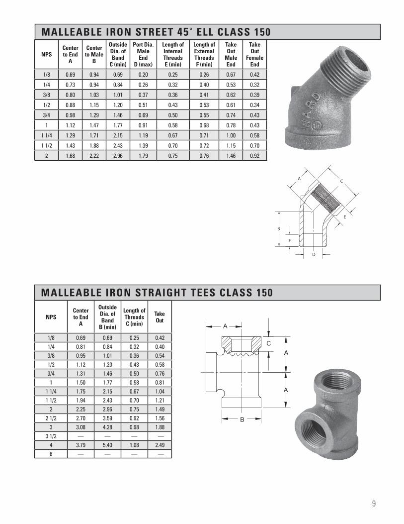
MALLEABLE IRON STREET 45˚ ELL CLASS 150
MALLEABLE IRON STRAIGHT TEES CLASS 150
NPSCenter to End
A
Outside Dia. of Band
B (min)
Length of Threads C (min)
Take Out
1/8 0.69 0.69 0.25 0.421/4 0.81 0.84 0.32 0.403/8 0.95 1.01 0.36 0.541/2 1.12 1.20 0.43 0.583/4 1.31 1.46 0.50 0.761 1.50 1.77 0.58 0.81
1 1/4 1.75 2.15 0.67 1.041 1/2 1.94 2.43 0.70 1.21
2 2.25 2.96 0.75 1.492 1/2 2.70 3.59 0.92 1.56
3 3.08 4.28 0.98 1.883 1/2 — — — —
4 3.79 5.40 1.08 2.496 — — — —
NPSCenter to End
A
Centerto Male
B
Outside Dia. of Band
C (min)
Port Dia. Male End
D (max)
Length of Internal Threads E (min)
Length of External Threads F (min)
Take Out
Male End
Take Out
Female End
1/8 0.69 0.94 0.69 0.20 0.25 0.26 0.67 0.42
1/4 0.73 0.94 0.84 0.26 0.32 0.40 0.53 0.32
3/8 0.80 1.03 1.01 0.37 0.36 0.41 0.62 0.39
1/2 0.88 1.15 1.20 0.51 0.43 0.53 0.61 0.34
3/4 0.98 1.29 1.46 0.69 0.50 0.55 0.74 0.43
1 1.12 1.47 1.77 0.91 0.58 0.68 0.78 0.43
1 1/4 1.29 1.71 2.15 1.19 0.67 0.71 1.00 0.58
1 1/2 1.43 1.88 2.43 1.39 0.70 0.72 1.15 0.70
2 1.68 2.22 2.96 1.79 0.75 0.76 1.46 0.92
������������������
A
B
C
E
D
F
����
����
����
����
��
A
A
A
C
B
9

MALLEABLE IRON REDUCING TEES CLASS 150
NPSCenter to End
X
Center to End
Y
Center to End
Z
OutsideDia.
H (min)
OutsideDia.
H2 (min)
OutsideDia.
H3 (min)
Thread Length B (min)
Thread Length
B2 (min)
Thread Length
B3 (min)
TakeOut
TakeOut
TakeOut
1/4 x 1/4 x 1/8 — — — — — — — — — — — —1/8 x 1/8 x 1/4 — — — — — — — — — — — —3/8 x 3/8 x 1/4 — — — — — — — — — — — —3/8 x 1/4 x 3/8 — — — — — — — — — — — —3/8 x 1/4 x 1/4 — — — — — — — — — — — —1/4 x 1/4 x 3/8 — — — — — — — — — — — —1/2 x 1/2 x 3/8 1.04 1.04 1.03 0.43 0.43 0.36 1.20 1.20 1.01 0.50 0.50 0.621/2 x 1/2 x 1/4 0.97 0.97 0.98 0.43 0.43 0.32 1.20 1.20 0.84 0.43 0.43 0.571/2 x 3/8 x 1/2 1.12 1.03 1.12 0.43 0.36 0.43 1.20 1.01 1.20 0.58 0.62 0.581/2 x 3/8 x 3/8 1.04 0.950 1.03 0.43 0.36 0.36 1.20 1.01 1.01 0.50 0.54 0.621/2 x 1/4 x 1/2 1.12 0.98 1.12 0.43 0.32 0.43 1.20 0.84 1.20 0.58 0.60 0.583/8 x 3/8 x 1/2 1.03 1.03 1.04 0.36 0.36 0.43 1.01 1.01 1.20 0.62 0.62 0.503/4 x 3/4 x 1/2 1.20 1.20 1.22 0.50 0.50 0.43 1.46 1.46 1.20 0.65 0.65 0.683/4 x 3/4 x 3/8 1.12 1.12 1.13 0.50 0.50 0.36 1.46 1.46 1.01 0.57 0.57 0.723/4 x 3/4 x 1/4 1.05 1.05 1.08 0.50 0.50 0.32 1.46 1.46 0.84 0.50 0.50 0.673/4 x 1/2 x 3/4 1.31 1.22 1.31 0.50 0.43 0.50 1.46 1.20 1.46 0.76 0.68 0.763/4 x 1/2 x 1/2 1.20 1.12 1.22 0.50 0.43 0.43 1.46 1.20 1.20 0.65 0.58 0.683/4 x 3/8 x 3/4 1.31 1.13 1.13 0.50 0.36 0.50 1.46 1.01 1.46 0.76 0.72 0.583/4 x 3/8 x 3/8 — — — — — — — — — — — —3/4 x 1/4 x 3/4 1.31 1.08 1.31 0.50 0.32 0.50 1.46 0.84 1.46 0.76 0.67 0.761/2 x 1/2 x 3/4 1.22 1.22 1.20 0.43 0.43 0.50 1.20 1.20 1.46 0.68 0.68 0.65
1 x 1 x 3/4 1.37 1.37 1.45 0.58 0.58 0.50 1.77 1.77 1.46 0.68 0.68 0.901 x 1 x 1/2 1.26 1.26 1.36 0.58 0.58 0.43 1.77 1.77 1.20 0.57 0.57 0.821 x 1 x 3/8 1.18 1.18 1.27 0.58 0.58 0.36 1.77 1.77 1.01 0.49 0.49 0.861 X 1 X 1/4 1.11 1.11 1.22 0.58 0.58 0.32 1.77 1.77 0.84 0.42 0.42 0.811 x 3/4 x 1 1.50 1.45 1.50 0.58 0.50 0.58 1.77 1.46 1.77 0.81 0.90 0.81
1 x 3/4 x 3/4 1.37 1.31 1.45 0.58 0.50 0.50 1.77 1.46 1.46 0.68 0.76 0.901 x 3/4 x 1/2 1.26 1.20 1.36 0.58 0.50 0.43 1.77 1.46 1.20 0.57 0.65 0.821 x 1/2 x 1 1.50 1.36 1.50 0.58 0.43 0.58 1.77 1.20 1.77 0.81 0.82 0.81
1 x 1/2 x 3/4 1.37 1.22 1.45 0.58 0.43 0.50 1.77 1.20 1.46 0.68 0.68 0.901 x 1/2 x 1/2 1.26 1.12 1.36 0.58 0.43 0.43 1.77 1.20 1.20 0.57 0.58 0.821 x 3/8 x 1 — — — — — — — — — — — —*1 x 1/4 x 1 1.50 1.20 1.50 0.58 0.32 0.58 1.77 0.84 1.77 0.81 0.79 0.811 x 1/8 x 1 — — — — — — — — — — — —
3/4 x 3/4 x 1 1.45 1.45 1.37 0.50 0.50 0.58 1.46 1.46 1.77 0.90 0.90 0.681/2 x 1/2 x 1 — — — — — — — — — — — —
1 1/4 x 1 1/4 x 1 1.58 1.58 1.67 0.67 0.67 0.58 2.15 2.15 1.77 0.87 0.87 0.981 1/4 x 1 1/4 x 3/4 1.45 1.45 1.62 0.67 0.67 0.50 2.15 2.15 1.46 0.74 0.74 1.071 1/4 x 1 1/4 x 1/2 1.34 1.34 1.53 0.67 0.67 0.43 2.15 2.15 1.20 0.63 0.63 0.991 1/4 x 1 1/4 x 3/8 — — — — — — — — — — — —1 1/4 x 1 x 1 1/4 1.75 1.67 1.75 0.67 0.58 0.67 2.15 1.77 2.15 1.04 0.98 1.04
1 1/4 x 1 x 1 1.58 1.50 1.67 0.67 0.58 0.58 2.15 1.77 1.77 0.87 0.81 0.981 1/4 x 1 x 3/4 1.45 1.37 1.62 0.67 0.58 0.50 2.15 1.77 1.46 0.74 0.68 1.071 1/4 x 1 x 1/2 1.34 1.26 1.53 0.67 0.58 0.43 2.15 1.77 1.20 0.63 0.57 0.99
1 1/4 x 3/4 x 1 1/4 1.75 1.62 1.75 0.67 0.50 0.67 2.15 1.46 2.15 1.04 1.07 1.041 1/4 x 3/4 x 1 1.58 1.45 1.67 0.67 0.50 0.58 2.15 1.46 1.77 0.87 0.90 0.98
1 1/4 x 3/4 x 3/4 1.45 1.31 1.62 0.67 0.50 0.50 2.15 1.46 1.46 0.74 0.76 1.071 1/4 x 1/2 x 1 1/4 1.75 1.53 1.75 0.67 0.43 0.67 2.15 1.20 2.15 1.04 0.99 1.04
1 1/4 x 1/2 x 1 — — — — — — — — — — — —1 x 1 x 1 1/4 1.67 1.67 1.58 0.58 0.58 0.67 1.77 1.77 2.15 0.98 0.96 0.87
3/4 x 3/4 x 1 1/4 — — — — — — — — — — — —1 1/2 x 1 1/2 x 1 1/4 1.82 1.82 1.88 0.70 0.70 0.67 2.43 2.43 2.15 1.09 1.09 1.17
1 1/2 x 1 1/2 x 1 1.65 1.65 1.80 0.70 0.70 0.58 2.43 2.43 1.77 0.92 0.92 1.111 1/2 x 1 1/2 x 3/4 1.52 1.52 1.75 0.70 0.70 0.50 2.43 2.43 1.46 0.79 0.79 1.201 1/2 x 1 1/2 x 1/2 1.41 1.41 1.66 0.70 0.70 0.43 2.43 2.43 1.20 0.68 0.68 1.12
1 1/2 x 1 1/4 x 1 1/2 1.94 1.88 1.94 0.70 0.67 0.70 2.43 2.15 2.43 1.21 1.17 1.211 1/2 x 1 1/4 x 1 1/4 1.82 1.75 1.88 0.70 0.67 0.67 2.43 2.15 2.15 1.09 1.04 1.17
1 1/2 x 1 1/4 x 1 1.65 1.58 1.80 0.70 0.67 0.58 2.43 2.15 1.77 0.92 0.87 1.111 1/2 x 1 1/4 x 3/4 1.52 1.45 1.75 0.70 0.67 0.50 2.43 2.15 1.46 0.79 0.74 1.201 1/2 x 1 1/4 x 1/2 1.41 1.34 1.66 0.70 0.67 0.43 2.43 2.15 1.20 0.68 0.63 1.12
* Manufactured to WARD specifications 10

* Manufactured to WARD specifications
NPSCenter to End
X
Center to End
Y
Center to End
Z
OutsideDia.
H (min)
OutsideDia.
H2 (min)
OutsideDia.
H3 (min)
Thread Length B (min)
Thread Length
B2 (min)
Thread Length
B3 (min)
TakeOut
TakeOut
TakeOut
1 1/2 x 1 x 1 1/2 1.94 1.80 1.94 0.70 0.58 0.70 2.43 1.77 2.43 1.21 1.11 1.211 1/2 x 1 x 1 1/4 — — — — — — — — — — — —
1 1/2 x 1 x 1 1.65 1.50 1.80 0.70 0.58 0.58 2.43 1.77 1.77 0.92 0.81 1.111 1/2 x 3/4 x 1 1/2 1.94 1.75 1.94 0.70 0.50 0.70 2.43 1.46 2.43 1.21 1.20 1.21*1 1/2 x 3/4 x 3/4 1.55 1.35 1.77 0.70 0.50 0.50 2.43 1.46 1.46 0.82 0.80 1.221 1/2 x 1/2 x 1 1/2 1.94 1.66 1.94 0.70 0.43 0.70 2.43 1.20 2.43 1.21 1.12 1.21
1 1/4 x 1 1/4 x 1 1/2 1.88 1.88 1.82 0.67 0.67 0.70 2.15 2.15 2.43 1.17 1.17 1.091 x 1 x 1 1/2 1.80 1.80 1.65 0.58 0.58 0.70 1.77 1.77 2.43 1.11 1.11 0.922 x 2 x 1 1/2 2.02 2.02 2.16 0.75 0.75 0.70 2.96 2.96 2.43 1.26 1.26 1.432 x 2 x 1 1/4 1.90 1.90 2.10 0.75 0.75 0.67 2.96 2.96 2.15 1.14 1.14 1.39
2 x 2 x 1 1.73 1.73 2.02 0.75 0.75 0.58 2.96 2.96 1.77 0.97 0.97 1.332 x 2 x 3/4 1.60 1.60 1.97 0.75 0.75 0.50 2.96 2.96 1.46 0.84 0.84 1.422 x 2 x 1/2 1.49 1.49 1.88 0.75 0.75 0.43 2.96 2.96 1.20 0.73 0.73 1.34
2 x 1 1/2 x 2 2.25 2.16 2.25 0.75 0.70 0.75 2.96 2.43 2.96 1.49 1.43 1.492 x 1 1/2 x 1 1/2 2.02 1.94 2.16 0.75 0.70 0.70 2.96 2.43 2.43 1.26 1.21 1.432 x 1 1/2 x 1 1/4 1.90 1.82 2.10 0.75 0.70 0.67 2.96 2.43 2.15 1.14 1.09 1.39
2 x 1 1/2 x 1 1.73 1.65 2.02 0.75 0.70 0.58 2.96 2.43 1.77 0.97 0.92 1.332 x 1 1/4 x 2 2.25 2.10 2.25 0.75 0.67 0.75 2.96 2.15 2.96 1.49 1.39 1.49
2 X 1 1/4 X 1 1/2 — — — — — — — — — — — —2 x 1 1/4 x 1 1/4 1.90 1.75 2.10 0.75 0.67 0.67 2.96 2.15 2.15 1.14 1.04 1.39
2 x 1 x 2 2.25 2.02 2.25 0.75 0.58 0.75 2.96 1.77 2.96 1.49 1.33 1.49*2 x 1 x 1 1.78 1.68 2.08 0.75 0.58 0.58 2.96 1.77 1.77 1.02 0.99 1.392 x 3/4 x 2 2.25 1.97 2.25 0.75 0.50 0.75 2.96 1.46 2.96 1.49 1.42 1.492 x 1/2 x 2 2.25 1.88 2.25 0.75 0.43 0.75 2.96 1.20 2.96 1.49 1.34 1.49
1 1/2 x 1 1/2 x 2 — — — — — — — — — — — —1 1/4 x 1 1/4 x 2 — — — — — — — — — — — —
1 x 1 x 2 — — — — — — — — — — — —2 1/2 x 2 1/2 x 2 2.39 2.39 2.60 0.92 0.92 0.75 3.59 3.59 2.96 1.25 1.25 1.84
2 1/2 x 2 1/2 x 1 1/2 2.16 2.16 2.51 0.92 0.92 0.70 3.59 3.59 2.43 1.02 1.02 1.782 1/2 x 2 1/2 x 1 1/4 2.04 2.04 2.45 0.92 0.92 0.67 3.59 3.59 2.15 0.90 0.90 1.74
2 1/2 x 2 1/2 x 1 1.87 1.87 2.37 0.92 0.92 0.58 3.59 3.59 1.77 0.73 0.73 1.682 1/2 x 2 1/2 x 3/4 1.74 1.74 2.32 0.92 0.92 0.50 3.59 3.59 1.46 0.60 0.60 1.772 1/2 x 2 x 2 1/2 — — — — — — — — — — — —
2 1/2 x 2 x 2 — — — — — — — — — — — —2 1/2 x 1 1/2 x 2 1/2 — — — — — — — — — — — —
2 1/2 x 1 1/2 x 2 — — — — — — — — — — — —2 x 2 x 2 1/2 — — — — — — — — — — — —3 x 3 x 2 1/2 2.83 2.83 2.99 0.98 0.98 0.92 4.28 4.28 3.59 1.63 1.63 1.85
3 x 3 x 2 2.52 2.52 2.89 0.98 0.98 0.75 4.28 4.28 2.96 1.32 1.32 2.133 x 3 x 1 1/2 2.29 2.29 2.80 0.98 0.98 0.70 4.28 4.28 2.43 1.09 1.09 2.073 x 3 x 1 1/4 2.17 2.17 2.74 0.98 0.98 0.67 4.28 4.28 2.15 0.97 0.97 2.03
3 x 3 x 1 2.00 2.00 2.66 0.98 0.98 0.58 4.28 4.28 1.77 0.80 0.80 1.973 x 3 x 3/4 1.87 1.87 2.61 0.98 0.98 0.50 4.28 4.28 1.46 0.67 0.67 2.06
3 x 2 1/2 x 2 1/2 — — — — — — — — — — — —3 x 2 1/2 x 2 — — — — — — — — — — — —
3 x 2 x 3 — — — — — — — — — — — —3 x 2 x 2 2.52 2.25 2.89 0.98 0.75 0.75 4.28 2.96 2.96 1.32 1.49 2.13
2 1/2 x 2 1/2 x 3 — — — — — — — — — — — —4 x 4 x 3 — — — — — — — — — — — —
4 x 4 x 2 1/2 — — — — — — — — — — — —4 x 4 x 2 2.74 2.74 3.41 1.08 1.08 0.75 5.40 5.40 2.96 1.44 1.44 2.65
4 x 4 x 1 1/2 — — — — — — — — — — — —4 x 3 x 4 — — — — — — — — — — — —
* Manufactured to WARD specifications
11

MALLEABLE IRON PIPE CAPS CLASS 150
MALLEABLE IRON WASTE NUTS CLASS 150
��
�������������������
A
B
NPS Overall Height A (min)
Outside Dia. of Band
B (min)
Length of ThreadsC (min)
*1/8 0.53 0.56 0.25+1/4 0.63 0.84 0.32+3/8 0.74 1.01 0.36+1/2 0.87 1.20 0.43+3/4 0.97 1.46 0.50
1 1.16 1.770 0.581 1/4 1.28 2.15 0.671 /2 1.33 2.43 0.70
2 1.45 3.00 0.752 1/2 1.70 3.59 0.92
3 1.80 4.28 0.983 1/2 — — —
4 2.08 5.40 1.085 — — —6 — — —8 — — —
NPS End to End A
HeightB
*1/2 2.42 0.34
*3/4 2.65 0.32
*1 2.99 0.37
+ Made in Malleable Iron and Steel* Made in Steel
������������������
A
B
C
* Manufactured to WARD specifications
12

MALLEABLE IRON STREET TEES CLASS 150
������������������
A
A
C
D
F
B
E
NPS Center to End
A
Centerto Male
B
OutsideDia. of Band
C (min)
Port Dia.MaleEnd
D (max)
Length of InternalThread E
(min)
Length of External Thread F
(min)
TakeOut
MaleEnd
TakeOut
FemaleEnd
1/4 — — — — — — — —3/8 — — — — — — — —1/2 — — — — — — — —3/4 1.31 1.89 1.46 0.69 0.50 0.55 1.34 0.761 1.50 2.14 1.77 0.91 0.58 0.68 1.45 0.81
1 1/4 1.75 2.45 2.15 1.19 0.67 0.71 1.74 1.041 1/2 1.94 2.69 2.43 1.39 0.70 0.72 1.96 1.21
2 2.25 3.26 2.96 1.79 0.75 0.76 2.50 1.49*1 1/4 x 1 x 1 1/4 1.75 2.45 2.15 0.91 0.67 0.68 1.76 1.04
* Manufactured to WARD specifications
�������������������
A
B
C
MALLEABLE IRON COUPLING, CLASS 150
NPS Length of Coupling
A
Outside Dia. of Band B
(min)
Length ofThreadsC (min)
TakeOut
+1/8 0.96 0.69 0.25 0.131/4 1.06 0.84 0.32 0.173/8 1.16 1.01 0.36 0.141/2 1.34 1.20 0.43 0.213/4 1.52 1.46 0.50 0.151 1.67 1.77 0.58 0.26
1 1/4 1.93 2.15 0.67 0.351 1/2 2.15 2.43 0.70 0.51
2 2.53 2.96 0.75 0.302 1/2 2.88 3.59 0.92 0.39
3 3.18 4.28 0.98 0.554 3.69 5.40 1.08 2.39
STRAIGHT COUPLING RIGHT & LEFT THREAD COUPLING
NPS Length of Coupling
A
Outside Dia. of Band B
(min)
Length ofThreadsC (min)
TakeOut
1/2 1.34 1.20 0.43 0.143/4 1.52 1.46 0.50 0.211 1.67 1.77 0.58 0.15
1 1/4 1.93 2.15 0.67 0.261 1/2 2.15 2.43 0.70 0.35
2 2.53 2.96 0.75 0.51
+ Steel
13

MALLEABLE IRON REDUCING COUPLING CLASS 150
NPS Length ofCoupling
A
Outside Dia.
Small Band
B (min)
Outside Dia.
LargeBand
B2 (min)
Length of Threads
Small End C (min)
Length of Threads
Large End C2 (min)
TakeOut
TakeOut
1/4 x 1/8 1.00 0.69 0.84 0.25 0.32 0.10 0.243/8 x 1/4 1.13 0.84 1.01 0.32 0.36 0.16 0.163/8 x 1/8 1.13 0.69 1.01 0.25 0.36 0.16 0.301/2 x 3/8 1.25 1.01 1.20 0.36 0.43 0.09 0.221/2 x 1/4 1.25 0.84 1.20 0.32 0.43 0.09 0.221/2 x 1/8 1.25 0.69 1.20 0.25 0.43 0.09 0.363/4 x 1/2 1.44 1.20 1.46 0.43 0.50 0.17 0.193/4 x 3/8 1.44 1.01 1.46 0.36 0.50 0.17 0.313/4 x 1/4 1.44 0.84 1.46 0.32 0.50 0.17 0.323/4 x 1/8 1.44 0.69 1.46 0.25 0.50 0.894 0.171 x 3/4 1.69 1.46 1.77 0.50 0.58 0.16 0.301 x 1/2 1.69 1.20 1.77 0.43 0.58 0.16 0.311 x 3/8 1.69 1.01 1.77 0.36 0.58 0.16 0.441 x 1/4 1.69 0.84 1.77 0.32 0.58 0.16 0.441 x 1/8 — — — — — — —
1 1/4 x 1 2.06 1.77 2.15 0.58 0.67 0.32 0.351 1/4 x 3/4 2.06 1.46 2.15 0.50 0.67 0.32 0.481 1/4 x 1/2 2.06 1.20 2.15 0.43 0.67 0.32 0.50
1 1/2 x 1 1/4 2.31 2.15 2.43 0.67 0.70 0.43 0.451 1/2 x 1 2.31 1.77 2.43 0.58 0.70 0.43 0.47
1 1/2 x 3/4 2.31 1.46 2.43 0.50 0.70 0.43 0.611 1/2 x 1/2 2.31 1.20 2.43 0.43 0.70 0.43 0.622 x 1 1/2 2.81 2.43 2.96 0.70 0.75 0.65 0.682 x 1 1/4 2.81 2.15 2.96 0.67 0.75 0.65 0.70
2 x 1 2.81 1.77 2.96 0.58 0.75 0.65 0.722 x 3/4 2.81 1.46 2.96 0.50 0.75 0.65 0.862 x 1/2 2.81 1.20 2.96 0.43 0.75 0.65 0.87
2 1/2 x 2 3.25 2.96 3.59 0.75 0.92 0.49 0.872 1/2 x 1 1/2 3.25 2.43 3.59 0.70 0.92 0.49 0.902 1/2 x 1 1/4 3.25 2.43 3.59 0.67 0.92 0.49 0.92
2 1/2 x 1 3.25 1.77 3.59 0.58 0.92 0.49 0.943 x 2 1/2 3.69 3.59 4.28 0.92 0.98 0.65 0.71
3 x 2 3.69 2.96 4.28 0.75 0.98 0.65 1.093 x 1 1/2 3.69 2.43 4.28 0.70 0.98 0.65 1.123 x 1 1/4 3.69 2.15 4.28 0.67 0.98 0.65 1.14
3 x 1 3.69 1.77 4.28 0.58 0.98 0.65 1.163 1/2 x 3 — — — — — — —3 1/2 x 2 — — — — — — —4 x 3 1/2 — — — —
4 x 3 4.38 4.28 5.40 0.98 1.08 0.89 0.994 x 2 1/2 4.38 3.59 5.40 0.92 1.08 0.89 1.05
4 x 2 4.38 2.96 5.40 0.75 1.08 0.89 1.434 x 1 1/2 — — — — — — —
5 x 4 — — — — — — —6 x 4 — — — — — — —
�������������������
A
B
B2
C
C2
14

MALLEABLE IRON EXTENSION PIECES CLASS 150
MALLEABLE IRON LOCKNUTS CLASS 150
MALLEABLE IRON RETURN BEND OPEN CLASS 150
NPS Overall Length
A
Length of Internal ThreadsB (min)
Length of External Threads C (min)
Take Out Female
End
Take Out Male End
*3/8 1.50 0.36 0.40 1.09 1.09*1/2 1.95 0.43 0.53 1.41 1.41*3/4 2.06 0.50 0.54 1.51 1.51*1 2.23 0.58 0.68 1.54 1.54
*1 1/4 2.56 0.67 0.63 1.85 1.85*2 — — — — —
NPS OverallHeight
A
Length-Across
Flat B (min)
Packing GrooveWidth
C
Packing GrooveDepth
D+1/8 0.19 0.69 0.50 0.04+1/4 0.25 0.84 0.66 0.063/8 0.28 1.00 0.77 0.061/2 0.31 1.18 0.97 0.063/4 0.34 1.43 1.23 0.061 0.38 1.75 1.50 0.06
1 1/4 0.42 2.10 1.86 0.061 1/2 0.47 2.35 2.12 0.06
2 0.53 2.88 2.63 0.09
NPS Center to Center
A
Outside Dia. ofBand
C (min)
Length ofThreadsD (min)
1/2 1.50 1.20 0.433/4 2.00 1.46 0.501 3.00 1.77 0.58
+STEELMade to ASME B16.14
* Manufactured to WARD specifications
������������������
A
C
B
D
������������������
AC
D
15

MALLEABLE IRON CROSS CLASS 150
MALLEABLE IRON 45˚ Y CLASS 150
������������������
A A
A
A
B
C
NPS Center to End
A
Outside Dia. of Band
B (min)
Length of ThreadsC (min)
TakeOut
1/8 — — — —1/4 0.81 0.84 0.32 0.403/8 0.95 1.01 0.36 0.541/2 1.12 1.20 0.43 0.583/4 1.31 1.46 0.50 0.761 1.50 1.77 0.58 0.81
1 1/4 1.75 2.15 0.67 1.041 1/2 1.94 2.43 0.70 1.21
2 2.25 2.96 0.75 1.492 1/2 — — — —
3 — — — —4 — — — —
NPS
Centerto End Inlet
A
Centerto End Outlet
B
End to End
C
OutsideDia. of Band
D (min)
Length of ThreadsE (min)
Take Out
Take Out
3/8 — — — — — — —
1/2 — — — — — — —
3/4 — — — — — — —
1 — — — — — — —
1 1/4 1.02 2.92 3.94 2.15 0.67 0.67 2.21
1 1/2 — — — — — — —
2 — — — — — — —
2 1/2 — — — — — — —
3 — — — — — — —
4 — — — — — — —
H H
D
D
E
D
E
C
E
AB
B
SECTION H-H
Section 1 Page 13 Malleable Iron 45 Y, Class 150
X.BM45Y
All information contained within this document is intended for the sole use of Ward Manufacturingand may not be released, used, copied, or distributed without the express written permission of ...
WARD MANUFACTURING LLCBLOSSBURG, PA. 16912, USA
(570) 638-2131
TITLE:
MATERIAL:
DRAWN BY:
SHEET:
DATE: CHECKED BY: DATE:
SCALE: SIZE: SMARTEAM I.D.:
DATE DESCRIPTION APR
PART NO.:
REV.
XX-XXXXXXXXX
E.C.O. #
NEW SOLIDWORKS DRAWING01 XXX
ANGULARITY: ±1
SURFACE FINISH:63
±.031 FOR THE FIRST INCH,AND AN ADDITIONAL ±.005
FOR EACH ADDITIONAL INCH
DECIMAL PLACE:.X ±.03.XX ±.01.XXX ±.005
AS-CAST SURFACES MACHINED SURFACESUN THREADS - EXTERNAL: CLASS 2A, INTERNAL: CLASS 2B
TOLERANCES AND SPECIFICATIONSUNLESS OTHERWISE NOTED:
THIS IS A CAD DRAWING,DO NOT ADD HAND WRITTEN EDITS
XX/XX/XX
M.I. 45° Y-BRANCH, CLASS 150
X.BM45YMalleable Iron ASTM A197
1 OF 1 B
ALL DIMENSIONS ARE IN INCHES UNLESS OTHERWISE NOTEDDRAWN IN ACCORDANCE WITH ASME Y14.5
BREAK ALL SHARP CORNERS AND REMOVE ALL BURRSDRAFT ANGLE IS 2° UNLESS NOTED OTHERWISE
THREADS:
REV.
16

SECTION 2
Material: ASTM A197
Dimensions: ASME B16.3 ANSI/ASME B1.20.1
Pressure ASME B16.3 Ratings:
Coatings: ASTM A153 ASTM B633
Additional UL, ULC, FM NSF 61 and Specifications: NSF 61 Annex G where applicable
Temp. F˚ Size
1/4 - 1Size
1 1/4 - 2Size
2 1/2 - 3
-20 TO 150 2000 1500 1000
200 1785 1350 910
250 1575 1200 825
300 1360 1050 735
350 1150 900 650
400 935 750 560
450 725 600 475
500 510 450 385
550 300 300 300
NPS O.D. ofBands
ThreadLength(min)
1/4 0.93 0.43
3/8 1.12 0.48
1/2 1.34 0.56
3/4 1.62 0.62
1 1.93 0.75
1 1/4 2.37 0.84
1 1/2 2.68 0.87
2 3.28 1.00
3 4.62 1.93
Extra Heavy Malleable Pipe Fit t ingsClass 300 - (A.A.R.)
General Dimensions
In InchesThese dimen-sions apply to both straight and reducing
fittings.
Table APressure-Temperature Ratings
SIZES
Ward Class 300 Malleable Iron Fittings are designed to handle higher pressures and more rugged service than our Class 150 fittings. Like all of Ward’s fittings, Class 300 fittings are made with the most sophisticated metallurgical and processing controls available. Ward’s quality assurance program ensures that the iron is made with high quality raw materials and processed according to rigorous standards. Iron samples are continuously analyzed to ensure that a close grained, high strength, non-porous iron is produced.
Ward starts with high quality iron, then accurately machines threads that comply with the precise standards developed by the American Society of Mechanical Engineers (ASME) and published as an American National Standard. The threads have an accurate form, thread length and straightness to allow them to easily engage thread pipe. In addition, Ward fittings have a chamfered opening to allow faster and easier pipe engagement. This feature also protects the fitting threads from damage during handling.
PSI
17
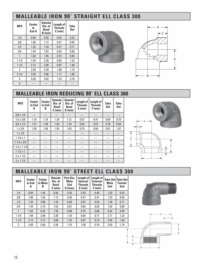
MALLEABLE IRON 90˚ STRAIGHT ELL CLASS 300
MALLEABLE IRON REDUCING 90˚ ELL CLASS 300
MALLEABLE IRON 90˚ STREET ELL CLASS 300
NPS Center to
End A
Outside Dia. of Band
B (min)
Length ofThreadsC (min)
TakeOut
1/4 0.94 0.93 0.43 0.533/8 1.06 1.12 0.47 0.651/2 1.25 1.34 0.57 0.713/4 1.44 1.63 0.64 0.891 1.63 1.95 0.75 0.94
1 1/4 1.94 2.39 0.84 1.231 1/2 2.13 2.68 0.87 1.40
2 2.50 3.28 1.00 1.742 1/2 2.94 3.86 1.17 1.80
3 3.38 4.62 1.23 2.184 — — — —
NPS Center to End
A
Center to End
B
Outside Dia. of Band
C (min)
Outside Dia. of Band
D (min)
Length of ThreadsE (min)
Length ofThreadsF (min)
TakeOut
TakeOut
3/8 x 1/4 — — — — — — — —1/2 x 3/8 1.19 1.19 1.34 1.12 0.57 0.47 0.65 0.783/4 x 1/2 1.31 1.38 1.63 1.34 0.64 0.57 0.76 0.841 x 3/4 1.50 1.56 1.95 1.63 0.75 0.64 0.81 1.011 x 1/2 — — — — — — — —
1 1/4 x 1 — — — — — — — —1 1/4 x 3/4 — — — — — — — —
1 1/2 x 1 1/4 — — — — — — — —1 1/2 x 1 — — — — — — — —2 x 1 1/2 — — — — — — — —2 x 1 1/4 — — — — — — — —
NPS Center to End
A
Center to Male
B
Outside Dia. of Band
C (min)
Port Dia.MaleEnd
D (max)
Length ofInternal ThreadsE (min)
Length ofExternal Threads F (min)
Take OutMaleEnd
Take OutFemale
End
1/4 0.94 1.44 0.93 0.26 0.43 0.40 1.03 0.533/8 1.06 1.63 1.12 0.36 0.47 0.41 1.22 0.651/2 1.25 2.00 1.34 0.49 0.57 0.53 1.46 0.713/4 1.44 2.19 1.63 0.67 0.64 0.55 1.64 0.891 1.63 0.25 1.95 0.88 0.75 0.68 0.42 0.94
1 1/4 1.94 2.88 2.39 1.16 0.84 0.71 2.17 1.231 1/2 2.13 3.13 2.68 1.35 0.87 0.72 2.40 1.40
2 2.50 3.69 3.28 1.75 1.00 0.76 2.93 1.74
�������������������
D
C
E
F
B
A
H H
D
E
C
F
B
A
SECTION H-H
Section 2 Page 15Malleable Iron 90 Street Ell, Class 300
X.B300SLAll information contained within this document is intended for the sole use of Ward Manufacturingand may not be released, used, copied, or distributed without the express written permission of ...
WARD MANUFACTURING LLCBLOSSBURG, PA. 16912, USA
(570) 638-2131
TITLE:
MATERIAL:
DRAWN BY:
SHEET:
DATE: CHECKED BY: DATE:
SCALE: SIZE: SMARTEAM I.D.:
DATE DESCRIPTION APR
PART NO.:
REV.
XX-XXXXXXXXX
E.C.O. #
NEW SOLIDWORKS DRAWING01 XXX
ANGULARITY: ±1
SURFACE FINISH:63
±.031 FOR THE FIRST INCH,AND AN ADDITIONAL ±.005
FOR EACH ADDITIONAL INCH
DECIMAL PLACE:.X ±.03.XX ±.01.XXX ±.005
AS-CAST SURFACES MACHINED SURFACESUN THREADS - EXTERNAL: CLASS 2A, INTERNAL: CLASS 2B
TOLERANCES AND SPECIFICATIONSUNLESS OTHERWISE NOTED:
THIS IS A CAD DRAWING,DO NOT ADD HAND WRITTEN EDITS
XX/XX/XX
2" 90° CLASS 300 M.I. STREET EL
X.B300SLMalleable Iron ASTM A197
1 OF 1 B
ALL DIMENSIONS ARE IN INCHES UNLESS OTHERWISE NOTEDDRAWN IN ACCORDANCE WITH ASME Y14.5
BREAK ALL SHARP CORNERS AND REMOVE ALL BURRSDRAFT ANGLE IS 2° UNLESS NOTED OTHERWISE
THREADS:
REV.
������������������
A
A
C
B
18
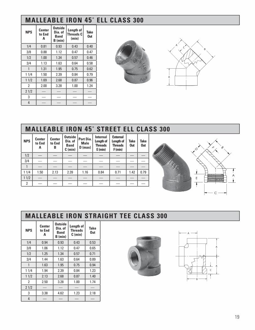
MALLEABLE IRON 45˚ ELL CLASS 300
MALLEABLE IRON STRAIGHT TEE CLASS 300
NPS Centerto End
A
OutsideDia. of Band
B (min)
Length ofThreads C
(min)
TakeOut
1/4 0.81 0.93 0.43 0.403/8 0.88 1.12 0.47 0.471/2 1.00 1.34 0.57 0.463/4 1.13 1.63 0.64 0.581 1.31 1.95 0.75 0.62
1 1/4 1.50 2.39 0.84 0.791 1/2 1.69 2.68 0.87 0.96
2 2.00 3.28 1.00 1.242 1/2 — — — —
3 — — — —4 — — — —
NPSCenter to End
A
Outside Dia. of Band
B (min)
Length ofThreads C (min)
TakeOut
1/4 0.94 0.93 0.43 0.533/8 1.06 1.12 0.47 0.651/2 1.25 1.34 0.57 0.713/4 1.44 1.63 0.64 0.891 1.63 1.95 0.75 0.94
1 1/4 1.94 2.39 0.84 1.231 1/2 2.13 2.68 0.87 1.40
2 2.50 3.28 1.00 1.742 1/2 — — — —
3 3.38 4.62 1.23 2.184 — — — —
MALLEABLE IRON 45˚ STREET ELL CLASS 300
NPS Centerto End
A
Center to End
B
Outside Dia. of Band
C (min)
Port Dia.Male
D (max)
Internal Length of ThreadsE (min)
External Length ofThreadsF (min)
TakeOut
TakeOut
1/2 — — — — — — — —3/4 — — — — — — — —1 — — — — — — — —
1 1/4 1.50 2.13 2.39 1.16 0.84 0.71 1.42 0.791 1/2 — — — — — — — —
2 — — — — — — — —
������������������
A
A
CB
������������������
A
A
A
B
C
HH
C
E
D F B
A
SECTION H-H
Section 2 Page 16Malleable Iron 45 Street Ell, Class 300
X.B300S45L
All information contained within this document is intended for the sole use of Ward Manufacturingand may not be released, used, copied, or distributed without the express written permission of ...
WARD MANUFACTURING LLCBLOSSBURG, PA. 16912, USA
(570) 638-2131
TITLE:
MATERIAL:
DRAWN BY:
SHEET:
DATE: CHECKED BY: DATE:
SCALE: SIZE: SMARTEAM I.D.:
DATE DESCRIPTION APR
PART NO.:
REV.
XX-XXXXXXXXX
E.C.O. #
NEW SOLIDWORKS DRAWING01 XXX
ANGULARITY: ±1
SURFACE FINISH:63
±.031 FOR THE FIRST INCH,AND AN ADDITIONAL ±.005
FOR EACH ADDITIONAL INCH
DECIMAL PLACE:.X ±.03.XX ±.01.XXX ±.005
AS-CAST SURFACES MACHINED SURFACESUN THREADS - EXTERNAL: CLASS 2A, INTERNAL: CLASS 2B
TOLERANCES AND SPECIFICATIONSUNLESS OTHERWISE NOTED:
THIS IS A CAD DRAWING,DO NOT ADD HAND WRITTEN EDITS
XX/XX/XX
1½" 45° STREET EL, CLASS 300
1D.B300SLMalleable Iron ASTM A197
1 OF 1 B
ALL DIMENSIONS ARE IN INCHES UNLESS OTHERWISE NOTEDDRAWN IN ACCORDANCE WITH ASME Y14.5
BREAK ALL SHARP CORNERS AND REMOVE ALL BURRSDRAFT ANGLE IS 2° UNLESS NOTED OTHERWISE
THREADS:
REV.
19

MALLEABLE IRON REDUCING TEES CLASS 300
NPS Center to End
A
Center to End
B
Center to End
C
Outside Dia. of Band
D (min)
Outside Dia. of Band
D2 (min)
Outside Dia. of Band
D3 (min)
Length of Threads E (min)
Length of ThreadsE2 (min)
Length of ThreadsE3 (min)
TakeOut
TakeOut
TakeOut
3/4 x 3/4 x 1/2 1.31 1.31 1.38 1.63 1.63 1.34 0.64 0.64 0.57 0.76 0.76 0.843/4 x 3/4 x 3/8 — — — — — — — — — — — —3/4 x 3/4 x 1/4 — — — — — — — — — — — —3/4 x 1/2 x 3/4 — — — — — — — — — — — —3/4 x 1/2 x 1/2 — — — — — — — — — — — —
1 x 1 x 3/4 1.50 1.50 1.56 1.95 1.95 1.63 0.75 0.75 0.64 0.81 0.81 1.011 x 1 x 1/2 1.44 1.44 1.50 1.95 1.95 1.34 0.75 0.75 0.57 0.75 0.75 0.961 x 1 x 1/4 — — — — — — — — — — — —1 x 3/4 x 1 — — — — — — — — — — — —
1 x 3/4 x 3/4 — — — — — — — — — — — —1 x 1/2 x 1 — — — — — — — — — — — —
1 1/4 x 1 1/4 x 1 1.75 1.75 1.81 2.39 2.39 1.95 0.84 0.84 0.75 1.04 1.04 1.121 1/4 x 1 1/4 x 3/4 1.63 1.63 1.75 2.39 2.39 1.63 0.84 0.84 0.64 0.92 0.92 1.201 1/4 x 1 1/4 x 1/2 — — — — — — — — — — — —
1 1/4 x 1 x 1 — — — — — — — — — — — —1 1/2 x 1 1/2 x 1 1/4 — — — — — — — — — — — —
1 1/2 x 1 1/2 x 1 1.81 1.81 2.00 2.68 2.68 1.95 0.87 0.87 0.75 1.08 1.08 1.311 1/2 x 1 1/2 x 3/4 1.69 1.69 1.88 2.68 2.68 1.63 0.87 0.87 0.64 0.96 0.96 1.331 1/2 x 1 1/2 x 1/2 1.63 1.63 1.81 2.68 2.68 1.34 0.87 0.87 0.57 0.90 0.90 1.27
2 x 2 x 1 1/2 2.25 2.25 2.38 3.28 3.28 2.68 1.00 1.00 0.87 1.49 1.49 1.652 x 2 x 1 1/4 — — — — — — — — — — — —
2 x 2 x 1 2.00 2.00 2.25 3.28 3.28 1.95 1.00 1.00 0.75 1.24 1.24 1.562 x 2 x 3/4 1.81 1.81 2.13 3.28 3.28 1.63 1.00 1.00 0.64 1.05 1.05 1.582 x 2 x1/2 1.75 1.75 2.06 3.28 3.28 1.34 1.00 1.00 0.57 0.99 0.99 1.52
2 x 1 1/2 x 2 — — — — — — — — — — — —2 1/2 x 2 1/2 x 2 — — — — — — — — — — — —
2 1/2 x 2 1/2 x 1 1/2 — — — — — — — — — — — —3 x 3 x 2 2.81 2.81 3.13 4.62 4.62 3.28 1.23 1.23 1.00 1.61 1.61 2.37
H H
D3
D2
C
E3
E2E
A B
D
SECTION H-H
Section 2 Page 17Malleable Iron Reducing Tee, Class 300
X.B300T
All information contained within this document is intended for the sole use of Ward Manufacturingand may not be released, used, copied, or distributed without the express written permission of ...
WARD MANUFACTURING LLCBLOSSBURG, PA. 16912, USA
(570) 638-2131
TITLE:
MATERIAL:
DRAWN BY:
SHEET:
DATE: CHECKED BY: DATE:
SCALE: SIZE: SMARTEAM I.D.:
DATE DESCRIPTION APR
PART NO.:
REV.
XX-XXXXXXXXX
E.C.O. #
NEW SOLIDWORKS DRAWING01 XXX
ANGULARITY: ±1
SURFACE FINISH:63
±.031 FOR THE FIRST INCH,AND AN ADDITIONAL ±.005
FOR EACH ADDITIONAL INCH
DECIMAL PLACE:.X ±.03.XX ±.01.XXX ±.005
AS-CAST SURFACES MACHINED SURFACESUN THREADS - EXTERNAL: CLASS 2A, INTERNAL: CLASS 2B
TOLERANCES AND SPECIFICATIONSUNLESS OTHERWISE NOTED:
THIS IS A CAD DRAWING,DO NOT ADD HAND WRITTEN EDITS
XX/XX/XX
REDUCING TEE, CLASS 300 (FOR CHARTED)
X.B300TMalleable Iron ASTM A197
1 OF 1 B
ALL DIMENSIONS ARE IN INCHES UNLESS OTHERWISE NOTEDDRAWN IN ACCORDANCE WITH ASME Y14.5
BREAK ALL SHARP CORNERS AND REMOVE ALL BURRSDRAFT ANGLE IS 2° UNLESS NOTED OTHERWISE
THREADS:
REV.
20

MALLEABLE IRON REDUCING COUPLING CLASS 300
MALLEABLE IRON STRAIGHT COUPLING CLASS 300
NPS Length ofCoupling
A
Outside Dia. of BandSmall End
B (min)
OutsideDia. of
Large End B2 (min)
Length of Threads
Small End C (min)
Length of Threads
Large EndC2 (min)
TakeOut
TakeOut
3/8 x 1/4 1.44 0.93 1.20 0.43 0.47 0.31 0.321/2 x 3/8 1.69 1.12 1.34 0.47 0.57 0.31 0.441/2 x 1/4 1.69 0.93 1.34 0.43 0.57 0.31 0.443/4 x 1/2 1.75 1.34 1.63 0.57 0.64 0.33 0.343/4 x 3/8 — — — — — — —3/4 x 1/4 — — — — — — —1 x 3/4 2.00 1.63 1.95 0.64 0.75 0.32 0.451 x 1/2 2.00 1.34 1.95 0.57 0.75 0.32 0.471 x 3/8 — — — — — — —1 x 1/4 — — — — — — —
1 1/4 x 1 2.38 1.95 2.39 0.75 0.84 0.48 0.511 1/4 x 3/4 2.38 1.63 2.39 0.64 0.84 0.48 0.641 1/4 x 1/2 — — — — — — —
1 1/2 x 1 1/4 2.69 2.39 2.68 0.84 0.87 0.62 0.641 1/2 x 1 2.69 1.95 2.68 0.75 0.87 0.62 0.66
1 1/2 x 3/4 2.69 1.63 2.68 0.64 0.87 0.62 0.801 1/2 x 1/2 — — — — — — —2 x 1 1/2 3.19 2.68 3.28 0.87 1.00 0.84 0.872 x 1 1/4 3.19 2.39 3.28 0.84 1.00 0.84 0.89
2 x 1 3.19 1.95 3.28 0.75 1.00 0.84 0.912 x 3/4 — — — — — — —2 x 1/2 — — — — — — —
2 1/2 x 2 — — — — — — —2 1/2 x 1 1/2 — — — — — — —
3 x 2 1/2 — — — — — — —3 x 2 — — — — — — —
3 x 1 1/2 — — — — — — —4 x 3 — — — — — — —4 x 2
NPS Length of Coupling A (min)
OutsideDia. of Band
B (min)
Length of ThreadsC (min)
TakeOut
1/4 1.37 0.93 0.43 0.283/8 1.62 1.12 0.47 0.401/2 1.87 1.34 0.57 0.403/4 2.12 1.63 0.64 0.511 2.37 1.95 0.75 0.50
1 1/4 2.87 2.39 0.84 0.731 1/2 2.87 2.68 0.87 0.71
2 3.62 3.28 1.00 1.052 1/2 — — — —
3 — — — —
�������������������
A
C
B
������������������
A
B
C
C2
B2
21

MALLEABLE IRON PIPE CAPS CLASS 300
NPS OverallHeight
A
Outside Dia. of Band
B (min)
Length of ThreadsC (min)
1/4 0.78 0.93 0.433/8 0.83 1.12 0.471/2 0.98 1.34 0.573/4 1.08 1.63 0.641 1.26 1.95 0.75
1 1/4 1.38 2.39 0.841 1/2 1.43 2.68 0.87
2 1.68 3.28 1.002 1/2 — — —
3 — — —
MALLEABLE IRON CROSS CLASS 300
������������������
A
A
AA
B
C
NPS Center to EndA (min)
Outside Dia. of Band
B (min)
Length of ThreadsC (min)
TakeOut
1/4 — — — —1/2 1.25 1.34 0.57 0.713/4 1.44 1.63 0.64 0.891 1.63 1.95 0.75 0.94
1 1/4 1.94 2.39 0.84 1.231 1/2 2.13 2.68 0.87 1.40
2 2.50 3.28 1.00 1.74
22

WARD UNIONS
Rugged-StrongMade of the Best Quality Malleable Iron
Extra heavy brass seat ring accurately machined to insure perfect seating under difficult conditions.
• Suitably Chamfered• Rust Resistant Treatment• Properly Threaded
Continuous, careful inspection during each manufacturing operation.
TYPES AVAILABLE
• Class 150 Brass-to-Iron• Class 250 Brass-to-Iron• Class 300 Brass-to-Iron• Class 150 All Iron Seat• Class 300 All Iron Seat
• Class 150 Gasket Unions• Class 300 Brass-to-Brass• Class 150 Di-Electric Unions (Female iron pipe to sweat copper)
23

SECTION 3 QUALITY PIPE UNIONS
Material: ASTM A197
Dimensions: ASME B16.39 ANSI/ASME B1.20.1
Pressure ASME B16.39 Ratings:
Coatings: ASTM A153, ASTM B633
Additional UL, ULC and FM where Specifications: applicable
Throughout the entire manufacturing process of WARD unions, special emphasis is placed upon the control and accuracy of each operation.
WARD unions are made from closely grained, high tensile iron and are produced under expert laboratory supervision. Modern methods of foundry practice and carefully supervised molding are combined to produce castings that are smooth and clean in every respect and free from imperfection.
WARD unions are manufactured in strict accordance with the requirements for threaded pipe unions standard, developed by American Society of Mechanical Engineers (ASME) and published as an American National Standard. Each opening is chamfered permitting easy assembly. WARD unions make up easily and pull tight for a sealed assembly.
Continuous and careful inspection by trained employees during and after each operation produces quality products which will give satisfaction to the user.
Temp.F Class 150 Class 250 Class 300
-20 to 150 300 500 600
200 265 455 550250 225 405 505300 185 460 460350 150 315 415400 110 270 370450 75 225 325500 * 180 280550 * 130 230
PSI
24
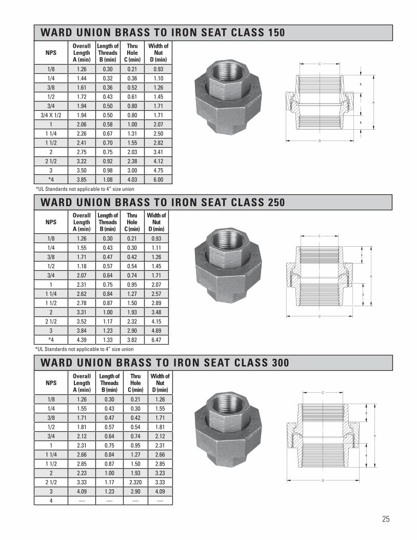
WARD UNION BRASS TO IRON SEAT CLASS 150
WARD UNION BRASS TO IRON SEAT CLASS 250
WARD UNION BRASS TO IRON SEAT CLASS 300
NPSOverallLengthA (min)
Length ofThreadsB (min)
ThruHole
C (min)
Width of Nut
D (min)
1/8 1.26 0.30 0.21 0.931/4 1.44 0.32 0.36 1.103/8 1.61 0.36 0.52 1.261/2 1.72 0.43 0.61 1.453/4 1.94 0.50 0.80 1.71
3/4 X 1/2 1.94 0.50 0.80 1.711 2.06 0.58 1.00 2.07
1 1/4 2.26 0.67 1.31 2.501 1/2 2.41 0.70 1.55 2.82
2 2.75 0.75 2.03 3.412 1/2 3.22 0.92 2.38 4.12
3 3.50 0.98 3.00 4.75*4 3.85 1.08 4.03 6.00
NPSOverall Length A (min)
Length of Threads B (min)
Thru Hole
C (min)
Width of Nut
D (min)
1/8 1.26 0.30 0.21 0.931/4 1.55 0.43 0.30 1.113/8 1.71 0.47 0.42 1.261/2 1.18 0.57 0.54 1.453/4 2.07 0.64 0.74 1.711 2.31 0.75 0.95 2.07
1 1/4 2.62 0.84 1.27 2.571 1/2 2.78 0.87 1.50 2.89
2 3.31 1.00 1.93 3.482 1/2 3.52 1.17 2.32 4.15
3 3.84 1.23 2.90 4.69*4 4.39 1.33 3.82 6.47
NPSOverall Length A (min)
Length of Threads B (min)
Thru Hole
C (min)
Width of Nut
D (min)
1/8 1.26 0.30 0.21 1.261/4 1.55 0.43 0.30 1.553/8 1.71 0.47 0.42 1.711/2 1.81 0.57 0.54 1.813/4 2.12 0.64 0.74 2.121 2.31 0.75 0.95 2.31
1 1/4 2.66 0.84 1.27 2.661 1/2 2.85 0.87 1.50 2.85
2 2.23 1.00 1.93 3.232 1/2 3.33 1.17 2.320 3.33
3 4.09 1.23 2.90 4.094 — — — —
*UL Standards not applicable to 4” size union
*UL Standards not applicable to 4” size union
H H
D
B
B
A
C
Section 3 Page 22Ward Union Brass to Iron Seat, Class 250
X.B250U
All information contained within this document is intended for the sole use of Ward Manufacturingand may not be released, used, copied, or distributed without the express written permission of ...
WARD MANUFACTURING LLCBLOSSBURG, PA. 16912, USA
(570) 638-2131
TITLE:
MATERIAL:
DRAWN BY:
SHEET:
DATE: CHECKED BY: DATE:
SCALE: SIZE: SMARTEAM I.D.:
DATE DESCRIPTION APR
PART NO.:
REV.
XX-XXXXXXXXX
E.C.O. #
NEW SOLIDWORKS DRAWING01 XXX
ANGULARITY: ±1
SURFACE FINISH:63
±.031 FOR THE FIRST INCH,AND AN ADDITIONAL ±.005
FOR EACH ADDITIONAL INCH
DECIMAL PLACE:.X ±.03.XX ±.01.XXX ±.005
AS-CAST SURFACES MACHINED SURFACESUN THREADS - EXTERNAL: CLASS 2A, INTERNAL: CLASS 2B
TOLERANCES AND SPECIFICATIONSUNLESS OTHERWISE NOTED:
THIS IS A CAD DRAWING,DO NOT ADD HAND WRITTEN EDITS
XX/XX/XX
2" UNION ASSEMBLY, CLASS 250, B-I
2.B250UMalleable Iron ASTM A197
1 OF 1 B
ALL DIMENSIONS ARE IN INCHES UNLESS OTHERWISE NOTEDDRAWN IN ACCORDANCE WITH ASME Y14.5
BREAK ALL SHARP CORNERS AND REMOVE ALL BURRSDRAFT ANGLE IS 2° UNLESS NOTED OTHERWISE
THREADS:
REV.
H H
B
B
A
D
C
Section 3 Page 22Ward Union Brass toIron Seat, Class 300
X.B300U
All information contained within this document is intended for the sole use of Ward Manufacturingand may not be released, used, copied, or distributed without the express written permission of ...
WARD MANUFACTURING LLCBLOSSBURG, PA. 16912, USA
(570) 638-2131
TITLE:
MATERIAL:
DRAWN BY:
SHEET:
DATE: CHECKED BY: DATE:
SCALE: SIZE: SMARTEAM I.D.:
DATE DESCRIPTION APR
PART NO.:
REV.
XX-XXXXXXXXX
E.C.O. #
NEW SOLIDWORKS DRAWING01 XXX
ANGULARITY: ±1
SURFACE FINISH:63
±.031 FOR THE FIRST INCH,AND AN ADDITIONAL ±.005
FOR EACH ADDITIONAL INCH
DECIMAL PLACE:.X ±.03.XX ±.01.XXX ±.005
AS-CAST SURFACES MACHINED SURFACESUN THREADS - EXTERNAL: CLASS 2A, INTERNAL: CLASS 2B
TOLERANCES AND SPECIFICATIONSUNLESS OTHERWISE NOTED:
THIS IS A CAD DRAWING,DO NOT ADD HAND WRITTEN EDITS
XX/XX/XX
1 OF 1 B
ALL DIMENSIONS ARE IN INCHES UNLESS OTHERWISE NOTEDDRAWN IN ACCORDANCE WITH ASME Y14.5
BREAK ALL SHARP CORNERS AND REMOVE ALL BURRSDRAFT ANGLE IS 2° UNLESS NOTED OTHERWISE
THREADS:
REV.
H H
C
A
B
B
D
Section 3 Page 22Ward Union Brass to Iron Seat, Class 150
X.BU
All information contained within this document is intended for the sole use of Ward Manufacturingand may not be released, used, copied, or distributed without the express written permission of ...
WARD MANUFACTURING LLCBLOSSBURG, PA. 16912, USA
(570) 638-2131
TITLE:
MATERIAL:
DRAWN BY:
SHEET:
DATE: CHECKED BY: DATE:
SCALE: SIZE: SMARTEAM I.D.:
DATE DESCRIPTION APR
PART NO.:
REV.
XX-XXXXXXXXX
E.C.O. #
NEW SOLIDWORKS DRAWING01 XXX
ANGULARITY: ±1
SURFACE FINISH:63
±.031 FOR THE FIRST INCH,AND AN ADDITIONAL ±.005
FOR EACH ADDITIONAL INCH
DECIMAL PLACE:.X ±.03.XX ±.01.XXX ±.005
AS-CAST SURFACES MACHINED SURFACESUN THREADS - EXTERNAL: CLASS 2A, INTERNAL: CLASS 2B
TOLERANCES AND SPECIFICATIONSUNLESS OTHERWISE NOTED:
THIS IS A CAD DRAWING,DO NOT ADD HAND WRITTEN EDITS
XX/XX/XX
2" UNION ASSEMBLY, CLASS 150, B-I
2.BUMalleable Iron ASTM A197
1 OF 1 B
ALL DIMENSIONS ARE IN INCHES UNLESS OTHERWISE NOTEDDRAWN IN ACCORDANCE WITH ASME Y14.5
BREAK ALL SHARP CORNERS AND REMOVE ALL BURRSDRAFT ANGLE IS 2° UNLESS NOTED OTHERWISE
THREADS:
REV.
25
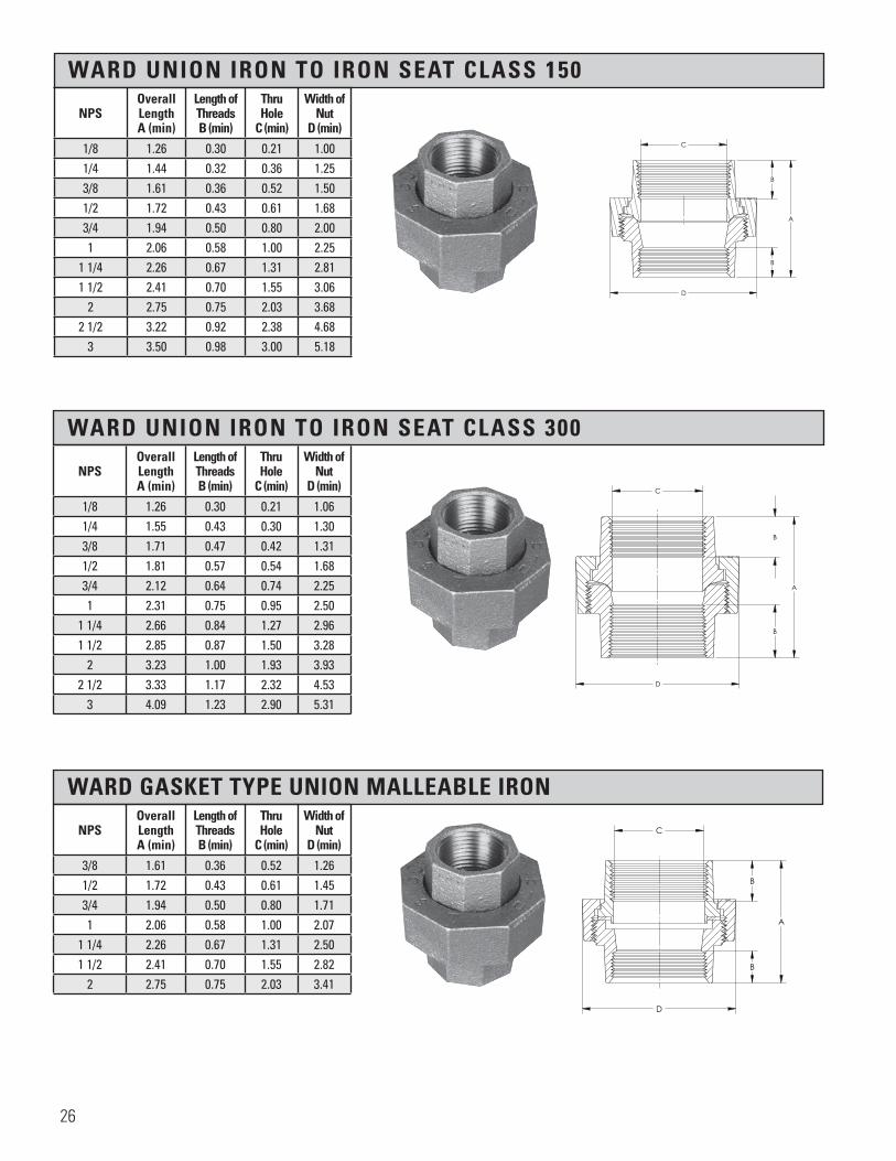
WARD UNION IRON TO IRON SEAT CLASS 150
NPSOverall Length A (min)
Length of Threads B (min)
Thru Hole
C (min)
Width of Nut
D (min)
1/8 1.26 0.30 0.21 1.001/4 1.44 0.32 0.36 1.253/8 1.61 0.36 0.52 1.501/2 1.72 0.43 0.61 1.683/4 1.94 0.50 0.80 2.001 2.06 0.58 1.00 2.25
1 1/4 2.26 0.67 1.31 2.811 1/2 2.41 0.70 1.55 3.06
2 2.75 0.75 2.03 3.682 1/2 3.22 0.92 2.38 4.68
3 3.50 0.98 3.00 5.18
H H
C
B
B
A
D
Section 3 Page 23Ward Union Iron to Iron,Class 150
X.BAIU All information contained within this document is intended for the sole use of Ward Manufacturingand may not be released, used, copied, or distributed without the express written permission of ...
WARD MANUFACTURING LLCBLOSSBURG, PA. 16912, USA
(570) 638-2131
TITLE:
MATERIAL:
DRAWN BY:
SHEET:
DATE: CHECKED BY: DATE:
SCALE: SIZE: SMARTEAM I.D.:
DATE DESCRIPTION APR
PART NO.:
REV.
XX-XXXXXXXXX
E.C.O. #
NEW SOLIDWORKS DRAWING01 XXX
ANGULARITY: ±1
SURFACE FINISH:63
±.031 FOR THE FIRST INCH,AND AN ADDITIONAL ±.005
FOR EACH ADDITIONAL INCH
DECIMAL PLACE:.X ±.03.XX ±.01.XXX ±.005
AS-CAST SURFACES MACHINED SURFACESUN THREADS - EXTERNAL: CLASS 2A, INTERNAL: CLASS 2B
TOLERANCES AND SPECIFICATIONSUNLESS OTHERWISE NOTED:
THIS IS A CAD DRAWING,DO NOT ADD HAND WRITTEN EDITS
XX/XX/XX
2" UNION ASSEMBLY, CLASS 150 A-I
2.BAIUMalleable Iron ASTM A197
1 OF 1 B
ALL DIMENSIONS ARE IN INCHES UNLESS OTHERWISE NOTEDDRAWN IN ACCORDANCE WITH ASME Y14.5
BREAK ALL SHARP CORNERS AND REMOVE ALL BURRSDRAFT ANGLE IS 2° UNLESS NOTED OTHERWISE
THREADS:
REV.
WARD UNION IRON TO IRON SEAT CLASS 300
NPSOverall Length A (min)
Length of Threads B (min)
Thru Hole
C (min)
Width of Nut
D (min)
1/8 1.26 0.30 0.21 1.061/4 1.55 0.43 0.30 1.303/8 1.71 0.47 0.42 1.311/2 1.81 0.57 0.54 1.683/4 2.12 0.64 0.74 2.251 2.31 0.75 0.95 2.50
1 1/4 2.66 0.84 1.27 2.961 1/2 2.85 0.87 1.50 3.28
2 3.23 1.00 1.93 3.932 1/2 3.33 1.17 2.32 4.53
3 4.09 1.23 2.90 5.31
H H
D
B
B
A
C
Section 3 Page 23Ward Union Iron To Iron , Class 300
X.BAI300U
All information contained within this document is intended for the sole use of Ward Manufacturingand may not be released, used, copied, or distributed without the express written permission of ...
WARD MANUFACTURING LLCBLOSSBURG, PA. 16912, USA
(570) 638-2131
TITLE:
MATERIAL:
DRAWN BY:
SHEET:
DATE: CHECKED BY: DATE:
SCALE: SIZE: SMARTEAM I.D.:
DATE DESCRIPTION APR
PART NO.:
REV.
XX-XXXXXXXXX
E.C.O. #
NEW SOLIDWORKS DRAWING01 XXX
ANGULARITY: ±1
SURFACE FINISH:63
±.031 FOR THE FIRST INCH,AND AN ADDITIONAL ±.005
FOR EACH ADDITIONAL INCH
DECIMAL PLACE:.X ±.03.XX ±.01.XXX ±.005
AS-CAST SURFACES MACHINED SURFACESUN THREADS - EXTERNAL: CLASS 2A, INTERNAL: CLASS 2B
TOLERANCES AND SPECIFICATIONSUNLESS OTHERWISE NOTED:
THIS IS A CAD DRAWING,DO NOT ADD HAND WRITTEN EDITS
XX/XX/XX
2" UNION ASSEMBLY, CLASS 300 A-I (UL)
2.BAI300UMalleable Iron ASTM A197
1 OF 1 B
ALL DIMENSIONS ARE IN INCHES UNLESS OTHERWISE NOTEDDRAWN IN ACCORDANCE WITH ASME Y14.5
BREAK ALL SHARP CORNERS AND REMOVE ALL BURRSDRAFT ANGLE IS 2° UNLESS NOTED OTHERWISE
THREADS:
REV.
WARD GASKET TYPE UNION MALLEABLE IRON
NPSOverall Length A (min)
Length of Threads B (min)
Thru Hole
C (min)
Width of Nut
D (min)
3/8 1.61 0.36 0.52 1.261/2 1.72 0.43 0.61 1.453/4 1.94 0.50 0.80 1.711 2.06 0.58 1.00 2.07
1 1/4 2.26 0.67 1.31 2.501 1/2 2.41 0.70 1.55 2.82
2 2.75 0.75 2.03 3.41
A A
D
C
A
B
B
WARD MANUFACTURING, INC.All information contained within this document is intended for the sole use of Ward Manufacturingand may not be released, used, copied, or distributed without the express written permission of.....
BLOSSBURG, PA. 16912, USA
TITLE: PART NO.:
MATERIAL:
DWN BY: CKD BY: FILE:
SHEET: SCALE: SIZE: DRAWING NO.:ANGULARITY: +/- 1 Deg. ANGULARITY: +/- 1Deg.
+/- .031 FOR THE FIRST INCH AND AN ADD'L+/- .005 FOR EACH ADD'L INCH
DECIMAL PLACE: .X+/- .03 .XX+/- .01 .XXX+/- .005
SURFACE FINISH:63
AS-CAST SURFACE MACHINED SURFACEUN THREADS - EXTERNAL: CLASS 2A, INTERNAL: CLASS 2B
TOLERANCES UNLESS OTHERWISE NOTED
DRAFT ANGLE IS 2 Deg. UNLESS NOTEDBREAK ALL SHARP CORNERS AND REMOVE ALL BURRS
ALL DIMENSIONS AND TOLERANCES PER ANSI Y14.5ALL DIMENSIONS IN INCHES UNLESS NOTED
REV. DATE E.C.O.# DESCRIPTION APR.
01 02/04/03 NEW SOLIDWORKS DRAWING MK
CLG 08/17/98 RNP 06/08/99 F0001361
55-0095042000 01
2.BGU
SEE PART DRAWINGS FOR MATERIAL
1 OF 1 1:1 C
02-161303020402
2" UNION ASSEMBLYCLASS 150 GASKETED
DATE: DATE:
26

WARD DI-ELECTRIC UNION IRON TO BRASS
WARD UNION BRASS TO BRASS SEAT CLASS 300
* Manufactured to WARD specifications
*UL Standards not applicable to 4” size unions
NPSOverall Length A (min)
Length of Threads B (min)
Thru Hole
C (min)
Width of Nut
D (min)
*1/2 x 1/2 1.87 0.57 0.54 1.68*3/4 x 1/2 1.87 0.64 0.74 1.68*3/4 x 3/4 1.31 0.64 0.74 1.68
NPSOverall Length A (min)
Length of Threads B (min)
Thru Hole
C (min)
Width of Nut
D (min)
1/4 1.55 0.43 0.30 1.333/8 1.71 0.47 0.42 1.501/2 1.81 0.57 0.54 1.763/4 2.12 0.64 0.74 2.151 2.31 0.75 0.95 2.48
1 1/4 2.66 0.84 1.27 3.021 1/2 2.85 0.87 1.50 3.28
2 2.23 1.00 1.93 3.962 1/2 3.33 1.17 2.32 4.72
3 4.09 1.23 2.90 5.37 *4 4.47 1.33 3.82 7.00
H H
C
A
B
D
Section 3 Page 24Ward Union Iron to Brass
E.GDEUW
All information contained within this document is intended for the sole use of Ward Manufacturingand may not be released, used, copied, or distributed without the express written permission of ...
WARD MANUFACTURING LLCBLOSSBURG, PA. 16912, USA
(570) 638-2131
TITLE:
MATERIAL:
DRAWN BY:
SHEET:
DATE: CHECKED BY: DATE:
SCALE: SIZE: SMARTEAM I.D.:
DATE DESCRIPTION APR
PART NO.:
REV.
XX-XXXXXXXXX
E.C.O. #
NEW SOLIDWORKS DRAWING01 XXX
ANGULARITY: ±1
SURFACE FINISH:63
±.031 FOR THE FIRST INCH,AND AN ADDITIONAL ±.005
FOR EACH ADDITIONAL INCH
DECIMAL PLACE:.X ±.03.XX ±.01.XXX ±.005
AS-CAST SURFACES MACHINED SURFACESUN THREADS - EXTERNAL: CLASS 2A, INTERNAL: CLASS 2B
TOLERANCES AND SPECIFICATIONSUNLESS OTHERWISE NOTED:
THIS IS A CAD DRAWING,DO NOT ADD HAND WRITTEN EDITS
XX/XX/XX
3/4" UNION ASSY, CLASS 150 DI-ELECTRIC
E.GDEUWMalleable Iron ASTM A197
1 OF 1 B
ALL DIMENSIONS ARE IN INCHES UNLESS OTHERWISE NOTEDDRAWN IN ACCORDANCE WITH ASME Y14.5
BREAK ALL SHARP CORNERS AND REMOVE ALL BURRSDRAFT ANGLE IS 2° UNLESS NOTED OTHERWISE
THREADS:
REV.
H H
B
B
A
D
C
Section 3 Page 24Ward Union Brass to Brass, Class 300
B.BBBU
All information contained within this document is intended for the sole use of Ward Manufacturingand may not be released, used, copied, or distributed without the express written permission of ...
WARD MANUFACTURING LLCBLOSSBURG, PA. 16912, USA
(570) 638-2131
TITLE:
MATERIAL:
DRAWN BY:
SHEET:
DATE: CHECKED BY: DATE:
SCALE: SIZE: SMARTEAM I.D.:
DATE DESCRIPTION APR
PART NO.:
REV.
XX-XXXXXXXXX
E.C.O. #
NEW SOLIDWORKS DRAWING01 XXX
ANGULARITY: ±1
SURFACE FINISH:63
±.031 FOR THE FIRST INCH,AND AN ADDITIONAL ±.005
FOR EACH ADDITIONAL INCH
DECIMAL PLACE:.X ±.03.XX ±.01.XXX ±.005
AS-CAST SURFACES MACHINED SURFACESUN THREADS - EXTERNAL: CLASS 2A, INTERNAL: CLASS 2B
TOLERANCES AND SPECIFICATIONSUNLESS OTHERWISE NOTED:
THIS IS A CAD DRAWING,DO NOT ADD HAND WRITTEN EDITS
XX/XX/XX
2½" UNION ASSEMBLY, CLASS 300, B-B
2D.BBBUMalleable Iron ASTM A197
1 OF 1 B
ALL DIMENSIONS ARE IN INCHES UNLESS OTHERWISE NOTEDDRAWN IN ACCORDANCE WITH ASME Y14.5
BREAK ALL SHARP CORNERS AND REMOVE ALL BURRSDRAFT ANGLE IS 2° UNLESS NOTED OTHERWISE
THREADS:
REV.
27
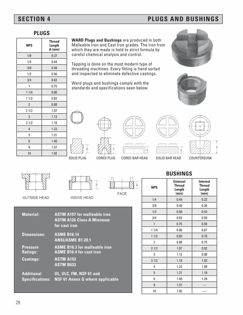
SECTION 4 PLUGS AND BUSHINGS
Material: ASTM A197 for malleable iron ASTM A126 Class A Minimum for cast iron
Dimensions: ASME B16.14 ANSI/ASME B1.20.1
Pressure ASME B16.3 for malleable iron Ratings: ASME B16.4 for cast iron
Coatings: ASTM A153 ASTM B633
Additional UL, ULC, FM, NSF 61 and Specifications: NSF 61 Annex G where applicable
NPSThreadLength A (min)
1/8 0.37
1/4 0.44
3/8 0.48
1/2 0.56
3/4 0.63
1 0.75
1 1/4 0.80
1 1/2 0.83
2 0.88
2 1/2 1.07
3 1.13
3 1/2 1.18
4 1.22
5 1.31
6 1.40
8 1.57
10 1.92
NPS
ExternalThread Length(min)
Internal ThreadLength(min)
1/4 0.44 0.32
3/8 0.48 0.36
1/2 0.56 0.43
3/4 0.63 0.50
1 0.75 0.58
1 1/4 0.80 0.67
1 1/2 0.83 0.70
2 0.88 0.75
2 1/2 1.07 0.92
3 1.13 0.98
3 1/2 1.18 1.03
4 1.22 1.08
5 1.31 1.18
6 1.40 1.28
8 1.57 —
10 1.92 —
WARD Plugs and Bushings are produced in both Malleable Iron and Cast Iron grades. The iron from which they are made is held to strict formula by careful chemical analysis and control.
Tapping is done on the most modern type of threading machines. Every fitting is hand sorted and inspected to eliminate defective castings.
Ward plugs and bushings comply with the standards and specifications seen below.
PLUGS
BUSHINGS
������������������
B
A
������������������
B
A
A
AA
A
D
C
SECTION H-H
B
A
D
SECTION K-K
Section 7 Page 26Cast Iron Cored Plugs, Class 125
X.BP
All information contained within this document is intended for the sole use of Ward Manufacturingand may not be released, used, copied, or distributed without the express written permission of ...
WARD MANUFACTURING LLCBLOSSBURG, PA. 16912, USA
(570) 638-2131
TITLE:
MATERIAL:
DRAWN BY:
SHEET:
DATE: CHECKED BY: DATE:
SCALE: SIZE: SMARTEAM I.D.:
DATE DESCRIPTION APR
PART NO.:
REV.
XX-XXXXXXXXX
E.C.O. #
NEW SOLIDWORKS DRAWING01 XXX
ANGULARITY: ±1
SURFACE FINISH:63
±.031 FOR THE FIRST INCH,AND AN ADDITIONAL ±.005
FOR EACH ADDITIONAL INCH
DECIMAL PLACE:.X ±.03.XX ±.01.XXX ±.005
AS-CAST SURFACES MACHINED SURFACESUN THREADS - EXTERNAL: CLASS 2A, INTERNAL: CLASS 2B
TOLERANCES AND SPECIFICATIONSUNLESS OTHERWISE NOTED:
THIS IS A CAD DRAWING,DO NOT ADD HAND WRITTEN EDITS
XX/XX/XX
1¼" CORED CAST IRON PLUG
1B.BPCast Iron
1 OF 1 B
ALL DIMENSIONS ARE IN INCHES UNLESS OTHERWISE NOTEDDRAWN IN ACCORDANCE WITH ASME Y14.5
BREAK ALL SHARP CORNERS AND REMOVE ALL BURRSDRAFT ANGLE IS 2° UNLESS NOTED OTHERWISE
THREADS:
REV.
A
H H
J J
D
C
SECTION H-H SCALE 1 : 1
D
C
B
SECTION J-J SCALE 1 : 1
Section 9 Page 25 & 26Cast Iron Solid Plugs, Class 125
X.BSP
All information contained within this document is intended for the sole use of Ward Manufacturingand may not be released, used, copied, or distributed without the express written permission of ...
WARD MANUFACTURING LLCBLOSSBURG, PA. 16912, USA
(570) 638-2131
TITLE:
MATERIAL:
DRAWN BY:
SHEET:
DATE: CHECKED BY: DATE:
SCALE: SIZE: SMARTEAM I.D.:
DATE DESCRIPTION APR
PART NO.:
REV.
XX-XXXXXXXXX
E.C.O. #
NEW SOLIDWORKS DRAWING01 XXX
ANGULARITY: ±1
SURFACE FINISH:63
±.031 FOR THE FIRST INCH,AND AN ADDITIONAL ±.005
FOR EACH ADDITIONAL INCH
DECIMAL PLACE:.X ±.03.XX ±.01.XXX ±.005
AS-CAST SURFACES MACHINED SURFACESUN THREADS - EXTERNAL: CLASS 2A, INTERNAL: CLASS 2B
TOLERANCES AND SPECIFICATIONSUNLESS OTHERWISE NOTED:
THIS IS A CAD DRAWING,DO NOT ADD HAND WRITTEN EDITS
XX/XX/XX
1/2" SQUARE HEAD SOLID PLUG
D.BSPCast Iron
1 OF 1 B
ALL DIMENSIONS ARE IN INCHES UNLESS OTHERWISE NOTEDDRAWN IN ACCORDANCE WITH ASME Y14.5
BREAK ALL SHARP CORNERS AND REMOVE ALL BURRSDRAFT ANGLE IS 2° UNLESS NOTED OTHERWISE
THREADS:
REV.
SOLID PLUG CORED PLUG CORED BAR HEAD SOLID BAR HEAD COUNTERSUNK
A
A A
A
H H
J J
D
C
SECTION H-H SCALE 1 : 1
D
C
B
SECTION J-J SCALE 1 : 1
Section 9 Page 25 & 26Cast Iron Solid Plugs, Class 125
X.BSP
All information contained within this document is intended for the sole use of Ward Manufacturingand may not be released, used, copied, or distributed without the express written permission of ...
WARD MANUFACTURING LLCBLOSSBURG, PA. 16912, USA
(570) 638-2131
TITLE:
MATERIAL:
DRAWN BY:
SHEET:
DATE: CHECKED BY: DATE:
SCALE: SIZE: SMARTEAM I.D.:
DATE DESCRIPTION APR
PART NO.:
REV.
XX-XXXXXXXXX
E.C.O. #
NEW SOLIDWORKS DRAWING01 XXX
ANGULARITY: ±1
SURFACE FINISH:63
±.031 FOR THE FIRST INCH,AND AN ADDITIONAL ±.005
FOR EACH ADDITIONAL INCH
DECIMAL PLACE:.X ±.03.XX ±.01.XXX ±.005
AS-CAST SURFACES MACHINED SURFACESUN THREADS - EXTERNAL: CLASS 2A, INTERNAL: CLASS 2B
TOLERANCES AND SPECIFICATIONSUNLESS OTHERWISE NOTED:
THIS IS A CAD DRAWING,DO NOT ADD HAND WRITTEN EDITS
XX/XX/XX
1/2" SQUARE HEAD SOLID PLUG
D.BSPCast Iron
1 OF 1 B
ALL DIMENSIONS ARE IN INCHES UNLESS OTHERWISE NOTEDDRAWN IN ACCORDANCE WITH ASME Y14.5
BREAK ALL SHARP CORNERS AND REMOVE ALL BURRSDRAFT ANGLE IS 2° UNLESS NOTED OTHERWISE
THREADS:
REV.
AA
28
A

CAST IRON SOLID PLUGS CLASS 125
CAST IRON CORED PLUGS CLASS 125
NPS
Nominal Width
Across Flats A
Distance Between
Lugs B (min)
Length of Threads C (min)
Height of SquareD (min)
*1/8 9/32 — 0.37 0.24
*1/4 3/8 — 0.44 0.28
*1/2 9/16 — 0.56 0.38
*3/4 5/8 — 0.63 0.44
*3/8 7/16 0.48 0.31
1 13/16 — 0.75 0.50
1 1/4 15/16 — 0.80 0.56
1 1/2 1 1/8 — 0.83 0.62
2 1 5/16 — 0.88 0.68
2 1/2 1 1/2 — 1.07 0.74
3 1 11/16 — 1.13 0.80
3 1/2 — — — —
+ 4 — 7/8 1.22 1.00
+ 5 — 7/8 1.31 1.00
+ 6 — 1 1/4 1.40 1.25
+8 — — — —
NPS
Nominal Width
Across Flats A
Distance Between
Lugs B (min)
Length of Threads C (min)
Height of SquareD (min)
1/2 9/16 --- 0.56 0.28
3/4 5/8 --- 0.63 0.44
1 13/16 --- 0.75 0.50
1 1/4 15/16 --- 0.80 0.56
1 1/2 1 1/8 --- 0.83 0.62
2 1 5/16 --- 0.88 0.68
2 1/2 1 1/2 --- 1.07 0.74
3 1 11/16 --- 1.13 0.80
3 1/2 1 7/8 --- 1.18 0.86
4 SQUARE 2 1/16 --- 1.22 0.92
+ 4 --- 7/8 1.22 1.00
+ 5 --- 7/8 1.31 1.00
+ 6 --- 1 1/4 1.40 1.25
+8 --- --- --- ---
*Made from Cast Iron or Steel
+ Bar Head
+ Bar Head
A
D
C
SECTION H-H
B
A
D
SECTION K-K
Section 7 Page 26Cast Iron Cored Plugs, Class 125
X.BP
All information contained within this document is intended for the sole use of Ward Manufacturingand may not be released, used, copied, or distributed without the express written permission of ...
WARD MANUFACTURING LLCBLOSSBURG, PA. 16912, USA
(570) 638-2131
TITLE:
MATERIAL:
DRAWN BY:
SHEET:
DATE: CHECKED BY: DATE:
SCALE: SIZE: SMARTEAM I.D.:
DATE DESCRIPTION APR
PART NO.:
REV.
XX-XXXXXXXXX
E.C.O. #
NEW SOLIDWORKS DRAWING01 XXX
ANGULARITY: ±1
SURFACE FINISH:63
±.031 FOR THE FIRST INCH,AND AN ADDITIONAL ±.005
FOR EACH ADDITIONAL INCH
DECIMAL PLACE:.X ±.03.XX ±.01.XXX ±.005
AS-CAST SURFACES MACHINED SURFACESUN THREADS - EXTERNAL: CLASS 2A, INTERNAL: CLASS 2B
TOLERANCES AND SPECIFICATIONSUNLESS OTHERWISE NOTED:
THIS IS A CAD DRAWING,DO NOT ADD HAND WRITTEN EDITS
XX/XX/XX
1¼" CORED CAST IRON PLUG
1B.BPCast Iron
1 OF 1 B
ALL DIMENSIONS ARE IN INCHES UNLESS OTHERWISE NOTEDDRAWN IN ACCORDANCE WITH ASME Y14.5
BREAK ALL SHARP CORNERS AND REMOVE ALL BURRSDRAFT ANGLE IS 2° UNLESS NOTED OTHERWISE
THREADS:
REV.
A
H H
J J
D
C
SECTION H-H SCALE 1 : 1
D
C
B
SECTION J-J SCALE 1 : 1
Section 9 Page 25 & 26Cast Iron Solid Plugs, Class 125
X.BSP
All information contained within this document is intended for the sole use of Ward Manufacturingand may not be released, used, copied, or distributed without the express written permission of ...
WARD MANUFACTURING LLCBLOSSBURG, PA. 16912, USA
(570) 638-2131
TITLE:
MATERIAL:
DRAWN BY:
SHEET:
DATE: CHECKED BY: DATE:
SCALE: SIZE: SMARTEAM I.D.:
DATE DESCRIPTION APR
PART NO.:
REV.
XX-XXXXXXXXX
E.C.O. #
NEW SOLIDWORKS DRAWING01 XXX
ANGULARITY: ±1
SURFACE FINISH:63
±.031 FOR THE FIRST INCH,AND AN ADDITIONAL ±.005
FOR EACH ADDITIONAL INCH
DECIMAL PLACE:.X ±.03.XX ±.01.XXX ±.005
AS-CAST SURFACES MACHINED SURFACESUN THREADS - EXTERNAL: CLASS 2A, INTERNAL: CLASS 2B
TOLERANCES AND SPECIFICATIONSUNLESS OTHERWISE NOTED:
THIS IS A CAD DRAWING,DO NOT ADD HAND WRITTEN EDITS
XX/XX/XX
1/2" SQUARE HEAD SOLID PLUG
D.BSPCast Iron
1 OF 1 B
ALL DIMENSIONS ARE IN INCHES UNLESS OTHERWISE NOTEDDRAWN IN ACCORDANCE WITH ASME Y14.5
BREAK ALL SHARP CORNERS AND REMOVE ALL BURRSDRAFT ANGLE IS 2° UNLESS NOTED OTHERWISE
THREADS:
REV.
A
D
C
SECTION H-H
B
A
D
SECTION K-K
Section 7 Page 26Cast Iron Cored Plugs, Class 125
X.BP
All information contained within this document is intended for the sole use of Ward Manufacturingand may not be released, used, copied, or distributed without the express written permission of ...
WARD MANUFACTURING LLCBLOSSBURG, PA. 16912, USA
(570) 638-2131
TITLE:
MATERIAL:
DRAWN BY:
SHEET:
DATE: CHECKED BY: DATE:
SCALE: SIZE: SMARTEAM I.D.:
DATE DESCRIPTION APR
PART NO.:
REV.
XX-XXXXXXXXX
E.C.O. #
NEW SOLIDWORKS DRAWING01 XXX
ANGULARITY: ±1
SURFACE FINISH:63
±.031 FOR THE FIRST INCH,AND AN ADDITIONAL ±.005
FOR EACH ADDITIONAL INCH
DECIMAL PLACE:.X ±.03.XX ±.01.XXX ±.005
AS-CAST SURFACES MACHINED SURFACESUN THREADS - EXTERNAL: CLASS 2A, INTERNAL: CLASS 2B
TOLERANCES AND SPECIFICATIONSUNLESS OTHERWISE NOTED:
THIS IS A CAD DRAWING,DO NOT ADD HAND WRITTEN EDITS
XX/XX/XX
1¼" CORED CAST IRON PLUG
1B.BPCast Iron
1 OF 1 B
ALL DIMENSIONS ARE IN INCHES UNLESS OTHERWISE NOTEDDRAWN IN ACCORDANCE WITH ASME Y14.5
BREAK ALL SHARP CORNERS AND REMOVE ALL BURRSDRAFT ANGLE IS 2° UNLESS NOTED OTHERWISE
THREADS:
REV.
29

COUNTERSUNK PLUGS CLASS 125 AND 150
NPS
Nominal Size of Square
A
Length of Threads B (min)
+1/4 1/4 0.44
+3/8 5/16 0.48
1/2 3/8 0.56
3/4 1/2 0.63
1 1/2 0.75
1 1/4 3/4 0.80
1 1/2 3/4 0.83
2 7/8 0.88
2 1/2 1 1/8 1.07
3 1 3/8 1.13
3 1/2 1 1/2 1.18
CAST IRON HEX HEAD CLEANOUT PLUGS CLASS 125
+Steel
* Manufactured to WARD specifications
NPSOverall Height
A
Length of Threads B (min)
Nominal Width
Across Flats C
1 1/4 1.03 0.53 1.01
1 1/2 1.02 0.52 1.01
2 1/2 1.25 0.62 1.20
3 1.37 0.68 1.40
4 1.40 0.77 1.54
������������������
B
A
������������������
B
A
������������������
AB
C
30

CAST IRON HEXAGON BUSHINGS CLASS 125
* Manufactured to WARD specifications
NPSWidth of
HeadA
Height of Head
B
Length of External Threads C (min)
Length of Internal Threads D (min)
Inside or Outside
Head
1 1/4 x 3/4 1.76 0.28 0.80 0.50 Outside
1 1/4 x 1/2 1.34 0.34 0.80 0.43 Inside
1 1/4 x 3/8 1.12 0.34 0.80 0.36 Inside
1 1/4 x 1/4 1.12 0.34 0.80 0.32 Inside
*1 1/4 x 1/8 1.12 0.34 0.80 0.32 Inside
1 1/2 x 1 2.00 0.31 0.83 0.58 Outside
1 1/2 x 3/4 1.63 0.37 0.83 0.50 Inside
1 1/2 x 1/2 1.34 0.37 0.83 0.43 Inside
1 1/2 x 3/8 — — — — Inside
1 1/2 x 1/4 1.12 0.37 0.83 0.32 Inside
*1 1/2 x 1/8 1.12 0.37 0.83 0.32 Inside
2 x 1 1/4 2.48 0.34 0.88 0.67 Outside
2 x 1 1.95 0.41 0.88 0.58 Inside
2 x 3/4 1.63 0.41 0.88 0.50 Inside
2 x 1/2 1.34 0.41 0.88 0.43 Inside
2 x 3/8 1.12 0.41 0.88 0.36 Inside
2 x 1/4 1.12 0.41 0.88 0.32 Inside
*2 x 1/8 1.12 0.41 0.88 0.32 Inside
2 1/2 x 1 1/2 2.68 0.44 1.07 0.70 Outside
2 1/2 x 1 1/4 2.39 0.44 1.07 0.67 Inside
2 1/2 x 1 1.95 0.44 1.07 0.58 Inside
2 1/2 x 3/4 1.63 0.44 1.07 0.50 Inside
2 1/2 x 1/2 1.34 0.44 1.07 0.43 Inside
*2 1/2 x 3/8 1.34 0.44 1.07 0.36 Inside
3 x 2 1/2 3.86 0.40 1.13 0.92 Outside
3 x 2 3.28 0.48 1.13 0.75 Outside
3 x 1 1/2 2.68 0.48 1.13 0.70 Inside
3 x 1 1/4 2.390 0.48 1.13 0.67 Inside
3 x 1 1.95 0.48 1.13 0.58 Inside
3 x 3/4 1.63 0.48 1.13 0.50 Inside
3 x 1/2 — — — — Inside
*3 x 1/4 2.68 0.48 1.13 0.32 Inside
3 1/2 x 2 1/2 3.86 0.52 1.18 0.92 Outside
3 1/2 x 2 3.28 0.52 1.18 0.75 Inside Continued on next page
A
B
C
D
AB
C
D
All information contained within this document is intended for the sole use of Ward Manufacturingand may not be released, used, copied, or distributed without the express written permission of ...
WARD MANUFACTURING LLCBLOSSBURG, PA. 16912, USA
(570) 638-2131
TITLE:
MATERIAL:
DRAWN BY:
SHEET:
DATE: CHECKED BY: DATE:
SCALE: SIZE: SMARTEAM I.D.:
DATE DESCRIPTION APR
PART NO.:
REV.
XX-XXXXXXXXX
E.C.O. #
NEW SOLIDWORKS DRAWING01 XXX
ANGULARITY: ±1
SURFACE FINISH:63
±.031 FOR THE FIRST INCH,AND AN ADDITIONAL ±.005
FOR EACH ADDITIONAL INCH
DECIMAL PLACE:.X ±.03.XX ±.01.XXX ±.005
AS-CAST SURFACES MACHINED SURFACESUN THREADS - EXTERNAL: CLASS 2A, INTERNAL: CLASS 2B
TOLERANCES AND SPECIFICATIONSUNLESS OTHERWISE NOTED:
THIS IS A CAD DRAWING,DO NOT ADD HAND WRITTEN EDITS
XX/XX/XX
INSIDE HEXAGON BUSHING
X.BBCast Iron
1 OF 1 B
ALL DIMENSIONS ARE IN INCHES UNLESS OTHERWISE NOTEDDRAWN IN ACCORDANCE WITH ASME Y14.5
BREAK ALL SHARP CORNERS AND REMOVE ALL BURRSDRAFT ANGLE IS 2° UNLESS NOTED OTHERWISE
THREADS:
REV.
31

CAST IRON HEXAGON BUSHINGS CLASS 125
* Manufactured to WARD specifications
NPSWidth of
HeadA
Height of Head
B
Length of External Threads C (min)
Length of Internal Threads D (min)
Inside or Outside
Head
3 1/2 x 1 1/2 — — — — Inside
3 1/2 x 1 1/4 2.39 0.52 1.18 0.67 Inside
3 1/2 x 1 1.95 0.52 1.18 0.58 Inside
*3 1/2 x 3/4 — — — — Inside
*3 1/2 x 1/2 — — — — Inside
*3 1/2 x 1/4 1.95 0.52 1.18 0.32 Inside
4 x 3 4.62 0.50 1.22 0.98 Outside
4 x 2 1/2 3.86 0.60 1.22 0.92 Inside
4 x 2 3.28 0.60 1.22 0.75 Inside
4 x 1 1/2 2.68 0.60 1.22 0.70 Inside
4 x 1 1/4 2.39 0.60 1.22 0.67 Inside
4 x 1 1.95 0.60 1.22 0.58 Inside
*4 x 3/4 — — — — Inside
*4 x 1/2 1.95 0.60 1.22 0.50 Inside
5 x 4 5.79 0.50 1.31 1.08 Outside
5 x 3 1/2 5.20 0.60 1.31 1.03 Outside
5 x 3 4.62 0.60 1.31 0.98 Inside
5 x 2 1/2 3.86 0.60 1.31 0.92 Inside
5 x 2 3.28 0.60 1.36 0.75 Inside
*5 x 1 1/2 3.28 0.60 1.31 0.70 Inside
*5 x 1 1/4 3.28 0.60 1.31 0.67 Inside
6 x 5 7.05 0.63 1.40 1.18 Outside
6 x 4 5.79 0.75 1.40 1.08 Inside
6 x 3 4.62 0.75 1.40 0.98 Inside
6 x 2 1/2 3.86 0.75 1.40 0.92 Inside
6 x 2 3.28 0.75 1.40 0.75 Inside
8 x 6 8.28 0.83 1.57 1.28 Outside
8 x 5 7.05 0.83 1.57 1.18 Inside
8 x 4 — — — — Inside
8 x 3 — — — — Inside
A
B
C
D
AB
C
D
All information contained within this document is intended for the sole use of Ward Manufacturingand may not be released, used, copied, or distributed without the express written permission of ...
WARD MANUFACTURING LLCBLOSSBURG, PA. 16912, USA
(570) 638-2131
TITLE:
MATERIAL:
DRAWN BY:
SHEET:
DATE: CHECKED BY: DATE:
SCALE: SIZE: SMARTEAM I.D.:
DATE DESCRIPTION APR
PART NO.:
REV.
XX-XXXXXXXXX
E.C.O. #
NEW SOLIDWORKS DRAWING01 XXX
ANGULARITY: ±1
SURFACE FINISH:63
±.031 FOR THE FIRST INCH,AND AN ADDITIONAL ±.005
FOR EACH ADDITIONAL INCH
DECIMAL PLACE:.X ±.03.XX ±.01.XXX ±.005
AS-CAST SURFACES MACHINED SURFACESUN THREADS - EXTERNAL: CLASS 2A, INTERNAL: CLASS 2B
TOLERANCES AND SPECIFICATIONSUNLESS OTHERWISE NOTED:
THIS IS A CAD DRAWING,DO NOT ADD HAND WRITTEN EDITS
XX/XX/XX
INSIDE HEXAGON BUSHING
X.BBCast Iron
1 OF 1 B
ALL DIMENSIONS ARE IN INCHES UNLESS OTHERWISE NOTEDDRAWN IN ACCORDANCE WITH ASME Y14.5
BREAK ALL SHARP CORNERS AND REMOVE ALL BURRSDRAFT ANGLE IS 2° UNLESS NOTED OTHERWISE
THREADS:
REV.
32
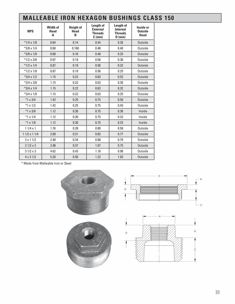
MALLEABLE IRON HEXAGON BUSHINGS CLASS 150
NPSWidth of
HeadA
Height of Head
B
Length of External Threads C (min)
Length of Internal Threads D (min)
Inside or Outside
Head
*1/4 x 1/8 0.64 0.14 0.44 0.26 Outside
*3/8 x 1/4 0.68 0.160 0.48 0.40 Outside
*3/8 x 1/8 0.68 0.16 0.48 0.25 Outside
*1/2 x 3/8 0.87 0.19 0.56 0.36 Outside
*1/2 x 1/4 0.87 0.19 0.56 0.32 Outside
*1/2 x 1/8 0.87 0.19 0.56 0.25 Outside
*3/4 x 1/2 1.15 0.22 0.63 0.53 Outside
*3/4 x 3/8 1.15 0.22 0.63 0.36 Outside
*3/4 x 1/4 1.15 0.22 0.63 0.32 Outside
*3/4 x 1/8 1.15 0.22 0.63 0.25 Outside
*1 x 3/4 1.42 0.25 0.75 0.50 Outside
*1 x 1/2 1.42 0.25 0.75 0.43 Outside
*1 x 3/8 1.12 0.30 0.75 0.36 Inside
*1 x 1/4 1.12 0.30 0.75 0.32 Inside
*1 x 1/8 1.12 0.30 0.75 0.25 Inside
1 1/4 x 1 1.76 0.28 0.80 0.58 Outside
1 1/2 x 1 1/4 2.00 0.31 0.83 0.77 Outside
2 x 1 1/2 2.48 0.34 0.88 0.70 Outside
2 1/2 x 2 2.98 0.37 1.07 0.75 Outside
3 1/2 x 3 4.62 0.43 1.18 0.98 Outside
4 x 3 1/2 5.20 0.50 1.22 1.03 Outside
* Made from Malleable Iron or Steel
A
B
C
D
AB
C
D
All information contained within this document is intended for the sole use of Ward Manufacturingand may not be released, used, copied, or distributed without the express written permission of ...
WARD MANUFACTURING LLCBLOSSBURG, PA. 16912, USA
(570) 638-2131
TITLE:
MATERIAL:
DRAWN BY:
SHEET:
DATE: CHECKED BY: DATE:
SCALE: SIZE: SMARTEAM I.D.:
DATE DESCRIPTION APR
PART NO.:
REV.
XX-XXXXXXXXX
E.C.O. #
NEW SOLIDWORKS DRAWING01 XXX
ANGULARITY: ±1
SURFACE FINISH:63
±.031 FOR THE FIRST INCH,AND AN ADDITIONAL ±.005
FOR EACH ADDITIONAL INCH
DECIMAL PLACE:.X ±.03.XX ±.01.XXX ±.005
AS-CAST SURFACES MACHINED SURFACESUN THREADS - EXTERNAL: CLASS 2A, INTERNAL: CLASS 2B
TOLERANCES AND SPECIFICATIONSUNLESS OTHERWISE NOTED:
THIS IS A CAD DRAWING,DO NOT ADD HAND WRITTEN EDITS
XX/XX/XX
INSIDE HEXAGON BUSHING
X.BBCast Iron
1 OF 1 B
ALL DIMENSIONS ARE IN INCHES UNLESS OTHERWISE NOTEDDRAWN IN ACCORDANCE WITH ASME Y14.5
BREAK ALL SHARP CORNERS AND REMOVE ALL BURRSDRAFT ANGLE IS 2° UNLESS NOTED OTHERWISE
THREADS:
REV.
33

CAST IRON FLUSH BUSHINGS CLASS 125
NPS
Length of External Threads A (min)
Length of Internal Threads B (min)
1 1/4 x 3/4 0.80 0.500
1 1/4 x 1/2 0.80 0.43
1 1/2 x 1 0.83 0.58
1 1/2 x 3/4 0.83 0.50
1 1/2 x 1/2 0.83 0.43
2 x 1 1/4 0.88 0.67
2 x 1 0.88 0.58
2 x 3/4 0.88 0.50
2 x 1/2 0.88 0.43
2 1/2 x 1 1/2 1.07 0.70
2 1/2 x 1 1/4 1.07 0.67
2 1/2 x 1 --- ---
2 1/2 x 3/4 --- ---
3 x 2 1.13 0.75
3 x 1 1/2 1.13 0.70
3 x 1 1/4 1.13 0.67
3 x 1 1.13 0.58
3 x 3/4 1.13 0.50
3 1/2 x 2 1/2 1.18 0.92
3 1/2 x 2 1.18 0.75
3 1/2 x 1 1/2 1.18 0.70
4 x 3 1.22 0.98
4 x 2 1/2 1.22 0.92
4 x 2 1.22 0.75
5 x 4 1.31 1.08
5 x 3 1.31 1.03
6 x 5 1.40 1.18
6 x 4 1.40 1.08
8 x 6 1.57 1.28
8 x 5 1.57 1.18
34

STEEL HEX SOCKET PLUGS
NPS
1/8
1/4
3/8
1/2
3/4
MALLEABLE IRON FLUSH BUSHINGS CLASS 150
NPSOverall Height
A
Length of External Threads B (min)
+1/4 x 1/8 0.44 0.26
+3/8 x 1/4 0.48 0.40
+1/2 x 3/8 0.56 0.41
+1/2 x 1/4 0.56 0.32
+1/2 x 1/8 0.56 0.25
+3/4 x 1/2 0.63 0.53
+3/4 x 3/8 0.63 0.36
+3/4 x 1/4 0.63 0.32
1 x 3/4 0.75 0.50
1 x 1/2 0.75 0.43
1 x 3/8 0.75 0.43
1 x 1/4 0.75 0.36
1 1/4 x 1 0.80 0.58
1 1/2 x 1 1/4 0.83 0.77
2 x 1 1/2 0.88 0.70
2 1/2 x 2 1.07 0.75
3 x 2 1/2 1.13 0.92
3 1/2 x 3 1.18 0.98
4 x 3 1/2 1.22 1.03
+Steel
35

CAST IRON DOUBLE TAP TANK BUSHINGS (Heavy Type Only)
NPSOverall Height
A
Length of External Threads B (min)
Width of Head
C
Inside or Outside
Head
*1 x 3/4 x 3/4 1.57 1.16 --- ---
*1 x 1/2 x 1/2 1.57 1.16 1.46 Outside
*1 1/2 x 1 x 1 1.58 1.16 2.02 Outside
*2 x 1 1/2 x 1 1/2 1.74 1.33 2.59 Outside
*2 x 1 1/4 x 1 1/4 1.77 1.33 2.59 Outside
*2 x 1 x 1 1.57 1.16 2.55 Outside
*2 x 3/4 x 3/4 1.57 1.16 2.55 Outside
*2 x 1/2 x 1/2 1.57 1.16 2.55 Outside
*2 x 3/8 x 3/8 1.57 1.16 2.55 Outside
*3 x 2 x 2 2.31 1.72 3.91 Outside
*3 x 1 x 1 2.31 1.72 3.91 Outside
*4 x 3 x 3 2.30 1.72 4.67 Outside
*4 x 2 1/2 x 2 1/2 2.30 1.55 3.30 Outside
*4 x 2 x 2 2.30 1.55 3.30 Inside
*4 x 1 1/2 x 1 1/2 2.30 1.55 3.30 Inside
*4 x 1 x 1 2.30 1.55 3.30 Inside
H H
C
BA
SECTION H-H
K K
C
B
A
SECTION K-K
Section 4 Page 33Cast Iron Double Tap Tank Bushing (Heavy Type Only)
X.BTBAll information contained within this document is intended for the sole use of Ward Manufacturingand may not be released, used, copied, or distributed without the express written permission of ...
WARD MANUFACTURING LLCBLOSSBURG, PA. 16912, USA
(570) 638-2131
TITLE:
MATERIAL:
DRAWN BY:
SHEET:
DATE: CHECKED BY: DATE:
SCALE: SIZE: SMARTEAM I.D.:
DATE DESCRIPTION APR
PART NO.:
REV.
XX-XXXXXXXXX
E.C.O. #
NEW SOLIDWORKS DRAWING01 XXX
ANGULARITY: ±1
SURFACE FINISH:63
±.031 FOR THE FIRST INCH,AND AN ADDITIONAL ±.005
FOR EACH ADDITIONAL INCH
DECIMAL PLACE:.X ±.03.XX ±.01.XXX ±.005
AS-CAST SURFACES MACHINED SURFACESUN THREADS - EXTERNAL: CLASS 2A, INTERNAL: CLASS 2B
TOLERANCES AND SPECIFICATIONSUNLESS OTHERWISE NOTED:
THIS IS A CAD DRAWING,DO NOT ADD HAND WRITTEN EDITS
XX/XX/XX
OUTSIDE HEAD TANK BUSHING
X.BTBCast Iron ASTM A126
1 OF 1 B
ALL DIMENSIONS ARE IN INCHES UNLESS OTHERWISE NOTEDDRAWN IN ACCORDANCE WITH ASME Y14.5
BREAK ALL SHARP CORNERS AND REMOVE ALL BURRSDRAFT ANGLE IS 2° UNLESS NOTED OTHERWISE
THREADS:
REV.
* Manufactured to WARD specifications
36

SECTION 5 TOP BEAM CLAMPS AND “C” CLAMPS
Material: ASTM A197
Coatings: ASTM A153 ASTM B633
Additional Specifications: UL, ULC AND FM where applicable
WARD Top Beam clamps and “C” clamps are manufactured from malleable iron with hardened steel cup point set screws and lock nuts. The finish is either black or galvanized.
Top Beam clamps are recommended for use under roof installations with bar joist type construction, or for attachment to the top flange of steel shapes.
“C” clamps are recommended for attachment to American Standard I-Beams and wide flange beams, where thickness of flange does not exceed .75 inches.
Care should be taken not to overtighten the set screw.
37

MALLEABLE IRON SMALL MOUTH TOP BEAM CLAMP
MALLEABLE IRON LARGE MOUTH TOP BEAM CLAMP
MALLEABLE IRON “C” CLAMP
NPS ThreadSize
RecommendedPipe Size Type Dim
ADim
BDim
CDim
DDim
EDim
FDim
G
3/8 3/8 - 16UNC 3/4- 4 SMALL 0.37 1.37 1.50 0.62 1.06 0.75 0.75
1/2 1/2 13UNC 5 - 8 SMALL 0.50 1.50 1.62 0.62 1.18 0.75 0.87
NPS ThreadSize
RecommendedPipe Size Type Dim
ADim
BDim
CDim
DDim
EDim
FDim
G
3/8 3/8- 16UNC 3/4 - 4 LARGE 0.37 1.56 1.50 0.62 1.06 0.75 0.98
1/2 1/2- 13UNC 5 - 8 LARGE 0.500 1.56 1.62 0.62 1.18 0.75 0.98
NPS ThreadSize
RecommendedPipe Size Type Dim
ADim
BDim
CDim
D
3/8 3/8 -16UNC 3/4 - 2 LARGE 0.37 0.625 1.750 1.30
1/2 1/2-13UNC 2 1/2 - 4 LARGE 0.50 0.625 1.750 1.30
38

SECTION 6 STANDARD CAST IRON PIPE FITTINGS CLASS 125, 250
Material: ASTM A126 Class A Minimum
Dimensions: ANSI/ASME B16.4 ANSI/ASME B1.20.1
Pressure ANSI/ASME B16.4 Ratings:
Coatings: ASTM A153 ASTM B633
Additional UL, ULC, FM, NSF 61 and Specifications: NSF 61 Annex G where applicable
NPSO.D. of Band(min)
ThreadLength(min)
MetalThickness
(min)
1/4 0.97 0.36 0.11
3/8 1.16 0.40 0.12
1/2 1.38 0.47 0.13
3/4 1.67 0.54 0.15
1 1.99 0.62 0.17
1 1/4 2.43 0.71 0.18
1 1/2 2.72 0.74 0.20
2 3.32 0.79 0.22
2 1/2 3.90 0.96 0.24
3 4.66 1.02 0.26
3 1/2 5.24 1.07 0.28
4 5.83 1.12 0.31
Temp F˚ CLASS 125 CLASS 250
-20 TO 150 175 400
200 165 370
250 150 340
300 140 310
350 125 (Note1) 300
400 — 250 (Note 2)
The iron from which Class 125 cast iron fittings are made is held to strict formula by careful chemical analysis and control.
Tapping is done on the most modern machines. All tappings are to USA Standards for iron pipe threads. Straightness and correct depth of threads is assured through continuous capable inspection, by careful trained inspectors.
Every fitting is hand sorted and inspected to eliminate defective castings.
WARD fittings are made to specifications published as American National Standards for pipe fittings.
A chamfer is cut or cast in all openings, permitting easy entrance of pipe and preventing damage to the first thread in handling and threading.
Because of the close attention paid to formula control and the use of modern precision equipment we are able to produce castings of rugged strength and the ability to make a water tight seal.
TEMPERATURE-PRESSURE RATING
Notes:1) Permissible for service temperature up to 360° F reflecting temperature of saturated steam at 125 psi.
2) Permissible for service temperature up to 406° F reflecting temperature of saturated steam at 250 psig.
PSI
39
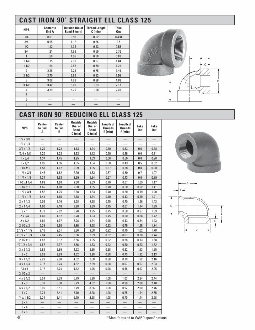
CAST IRON 90˚ STRAIGHT ELL CLASS 125
CAST IRON 90˚ REDUCING ELL CLASS 125
*Manufactured to WARD specifications
NPS Center to End A
Outside Dia.of Band B (min)
Thread LengthC (min)
Take Out
1/4 0.81 0.93 0.32 0.4083/8 0.95 1.12 0.36 0.51/2 1.12 1.34 0.43 0.583/4 1.31 1.63 0.50 0.761 1.50 1.95 0.58 0.81
1 1/4 1.75 2.39 0.67 1.041 1/2 1.94 2.68 0.70 1.21
2 2.25 3.28 0.75 1.492 1/2 2.70 3.86 0.92 1.56
3 3.08 4.62 0.98 1.883 1/2 3.42 5.20 1.03 2.17
4 3.79 5.79 1.08 2.495 — — — —6 — — — —8 — — — —
NPSCenter to End
A
Center to End
B
Outside Dia. ofBand
C (min)
Outside Dia. ofBand
D (min)
Length of ThreadsE (min)
Length of ThreadsF (min)
Take Out
Take Out
1/2 x 3/8 — — — — — — — — 1/2 x 1/4 — — — — — — — — 3/4 x 1/2 1.20 1.22 1.63 1.34 0.50 0.43 0.6 0.68
*3/4 x 3/8 1.20 1.22 1.63 1.12 0.50 0.36 0.6 0.811 x 3/4 1.37 1.45 1.95 1.63 0.58 0.50 0.6 0.901 x 1/2 1.26 1.36 1.95 1.34 0.58 0.43 0.5 0.82
1 1/4 x 1 1.58 1.67 2.39 1.95 0.67 0.58 0.8 0.981 1/4 x 3/4 1.45 1.62 2.39 1.63 0.67 0.50 0.7 1.071 1/4 x 1/2 1.34 1.53 2.39 1.34 0.67 0.43 0.6 0.99
1 1/2 x1 1/4 1.82 1.88 2.68 2.39 0.70 0.67 1.09 1.171 1/2 x 1 1.65 1.80 2.68 1.95 0.70 0.58 0.92 1.11
1 1/2 x 3/4 1.52 1.75 2.68 1.63 0.70 0.50 0.79 1.201 1/2 x 1/2 1.41 1.66 2.68 1.34 0.70 0.43 0.79 1.212 x 1 1/2 2.02 2.16 3.28 2.68 0.75 0.70 1.26 1.432 x 1 1/4 1.90 2.10 3.28 2.39 0.75 0.67 1.14 1.39
2 x 1 1.73 2.02 3.28 1.95 0.75 0.58 0.97 1.332 x 3/4 1.60 1.97 3.28 1.63 0.75 0.50 0.84 1.422 x 1/2 1.60 1.97 3.28 1.34 0.75 0.43 0.84 1.43
2 1/2 x 2 2.39 2.60 3.86 3.28 0.92 0.75 1.25 1.842 1/2 x 1 1/2 2.16 2.51 3.86 2.68 0.92 0.70 1.02 1.782 1/2 x 1 1/4 2.04 2.45 3.86 2.39 0.92 0.67 0.90 1.74
2 1/2 x 1 1.87 2.37 3.86 1.95 0.92 0.58 0.73 1.68*2 1/2 x 3/4 1.87 2.37 3.86 1.63 0.92 0.50 0.73 1.82
3 x 2 1/2 2.83 2.99 4.62 3.86 0.98 0.92 1.63 1.853 x 2 2.52 2.89 4.62 3.28 0.98 0.75 1.32 2.13
3 x 1 1/2 2.29 2.80 4.62 2.68 0.98 0.70 1.32 2.163 x 1 1/4 2.17 2.74 4.62 2.39 0.98 0.67 0.97 2.03
*3 x 1 2.17 2.74 4.62 1.95 0.98 0.58 0.97 2.053 1/2 x 3 — — — — — — — —4 x 3 1/2 3.54 3.69 5.79 5.20 1.08 1.03 2.24 2.44
4 x 3 3.30 3.60 5.79 4.62 1.08 0.98 2.00 2.404 x 2 1/2 3.05 3.51 5.79 3.86 1.08 0.92 2.00 2.46
4 x 2 2.74 3.41 5.79 3.28 1.08 0.75 1.44 2.65*4 x 1 1/2 2.74 3.41 5.79 2.68 1.08 0.70 1.44 2.68
5 x 4 — — — — — — — — 6 x 4 — — — — — — — — 6 x 3 — — — — — — — —
������������������
A
B
C
A
�������������������
B
D
C
E
A
F
40

CAST IRON 45˚ ELL CLASS 125
CAST IRON STRAIGHT TEE CLASS 125
NPSCenterto End
A
OutsideDia. ofBand
B (min)
Length of ThreadsC (min)
Take Out
1/4 — — — —
3/8 0.95 1.12 0.36 0.54
1/2 1.12 1.34 0.43 0.58
3/4 1.31 1.63 0.50 0.76
1 1.50 1.95 0.58 0.81
1 1/4 1.75 2.39 0.67 1.04
1 1/2 1.94 2.68 0.70 1.21
2 2.25 3.28 0.75 1.49
2 1/2 2.70 3.86 0.92 1.56
3 3.08 4.62 0.98 1.88
3 1/2 3.42 5.20 1.03 2.17
4 3.79 5.79 1.08 2.49
5 — — — —
6 — — — —
NPSCenter to End
A
OutsideDia. ofBand
B (min)
Length of ThreadsC (min)
Take Out
1/4 — — — —
3/8 — — — —
1/2 0.88 1.34 0.43 0.34
3/4 0.98 1.63 0.50 0.43
1 1.12 1.95 0.58 0.43
1 1/4 1.29 2.39 0.67 0.58
1 1/2 1.43 2.68 0.70 0.70
2 1.68 3.28 0.75 0.92
2 1/2 1.95 3.86 0.92 0.81
3 2.17 4.62 0.98 0.97
3 1/2 — — — —
4 2.61 5.79 1.08 1.31
5 — — — —
6 — — — —
�����������������
A
A
A
B
C
41
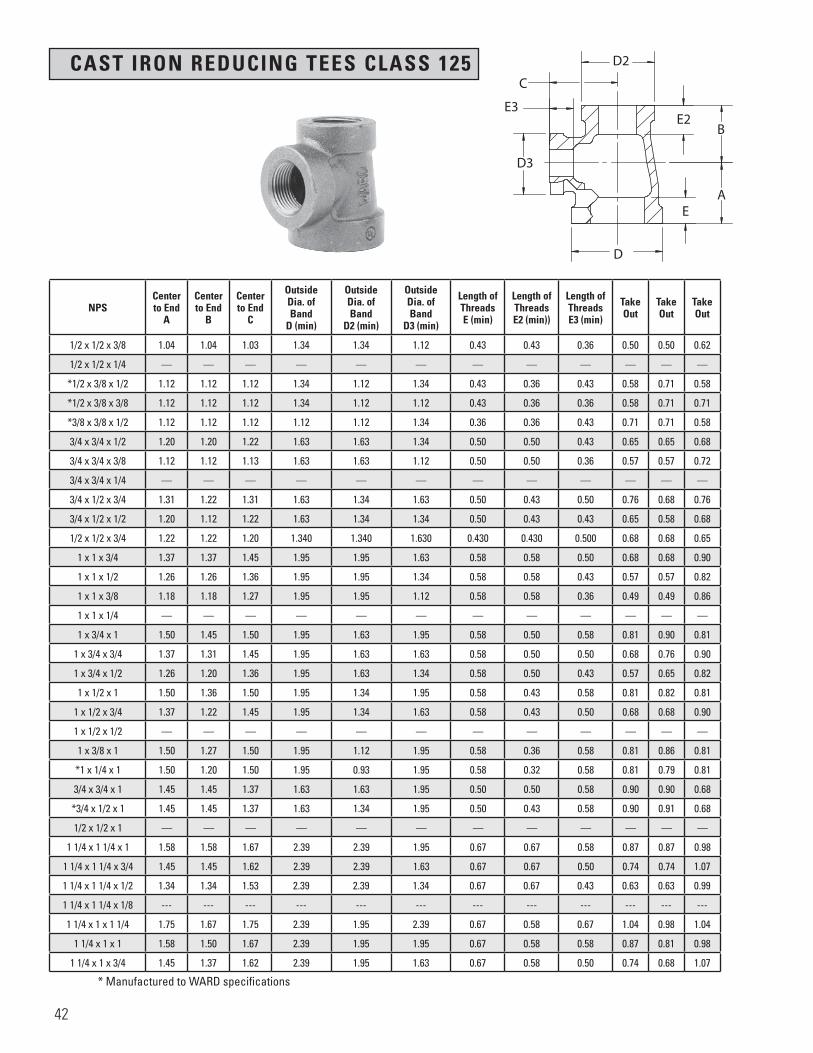
CAST IRON REDUCING TEES CLASS 125
* Manufactured to WARD specifications
NPSCenterto End
A
Centerto End
B
Centerto End
C
Outside Dia. ofBand
D (min)
Outside Dia. ofBand
D2 (min)
Outside Dia. ofBand
D3 (min)
Length of ThreadsE (min)
Length of ThreadsE2 (min))
Length of ThreadsE3 (min)
Take Out
Take Out
Take Out
1/2 x 1/2 x 3/8 1.04 1.04 1.03 1.34 1.34 1.12 0.43 0.43 0.36 0.50 0.50 0.62
1/2 x 1/2 x 1/4 — — — — — — — — — — — —
*1/2 x 3/8 x 1/2 1.12 1.12 1.12 1.34 1.12 1.34 0.43 0.36 0.43 0.58 0.71 0.58
*1/2 x 3/8 x 3/8 1.12 1.12 1.12 1.34 1.12 1.12 0.43 0.36 0.36 0.58 0.71 0.71
*3/8 x 3/8 x 1/2 1.12 1.12 1.12 1.12 1.12 1.34 0.36 0.36 0.43 0.71 0.71 0.58
3/4 x 3/4 x 1/2 1.20 1.20 1.22 1.63 1.63 1.34 0.50 0.50 0.43 0.65 0.65 0.68
3/4 x 3/4 x 3/8 1.12 1.12 1.13 1.63 1.63 1.12 0.50 0.50 0.36 0.57 0.57 0.72
3/4 x 3/4 x 1/4 — — — — — — — — — — — —
3/4 x 1/2 x 3/4 1.31 1.22 1.31 1.63 1.34 1.63 0.50 0.43 0.50 0.76 0.68 0.76
3/4 x 1/2 x 1/2 1.20 1.12 1.22 1.63 1.34 1.34 0.50 0.43 0.43 0.65 0.58 0.68
1/2 x 1/2 x 3/4 1.22 1.22 1.20 1.340 1.340 1.630 0.430 0.430 0.500 0.68 0.68 0.65
1 x 1 x 3/4 1.37 1.37 1.45 1.95 1.95 1.63 0.58 0.58 0.50 0.68 0.68 0.90
1 x 1 x 1/2 1.26 1.26 1.36 1.95 1.95 1.34 0.58 0.58 0.43 0.57 0.57 0.82
1 x 1 x 3/8 1.18 1.18 1.27 1.95 1.95 1.12 0.58 0.58 0.36 0.49 0.49 0.86
1 x 1 x 1/4 — — — — — — — — — — — —
1 x 3/4 x 1 1.50 1.45 1.50 1.95 1.63 1.95 0.58 0.50 0.58 0.81 0.90 0.81
1 x 3/4 x 3/4 1.37 1.31 1.45 1.95 1.63 1.63 0.58 0.50 0.50 0.68 0.76 0.90
1 x 3/4 x 1/2 1.26 1.20 1.36 1.95 1.63 1.34 0.58 0.50 0.43 0.57 0.65 0.82
1 x 1/2 x 1 1.50 1.36 1.50 1.95 1.34 1.95 0.58 0.43 0.58 0.81 0.82 0.81
1 x 1/2 x 3/4 1.37 1.22 1.45 1.95 1.34 1.63 0.58 0.43 0.50 0.68 0.68 0.90
1 x 1/2 x 1/2 — — — — — — — — — — — —
1 x 3/8 x 1 1.50 1.27 1.50 1.95 1.12 1.95 0.58 0.36 0.58 0.81 0.86 0.81
*1 x 1/4 x 1 1.50 1.20 1.50 1.95 0.93 1.95 0.58 0.32 0.58 0.81 0.79 0.81
3/4 x 3/4 x 1 1.45 1.45 1.37 1.63 1.63 1.95 0.50 0.50 0.58 0.90 0.90 0.68
*3/4 x 1/2 x 1 1.45 1.45 1.37 1.63 1.34 1.95 0.50 0.43 0.58 0.90 0.91 0.68
1/2 x 1/2 x 1 — — — — — — — — — — — —
1 1/4 x 1 1/4 x 1 1.58 1.58 1.67 2.39 2.39 1.95 0.67 0.67 0.58 0.87 0.87 0.98
1 1/4 x 1 1/4 x 3/4 1.45 1.45 1.62 2.39 2.39 1.63 0.67 0.67 0.50 0.74 0.74 1.07
1 1/4 x 1 1/4 x 1/2 1.34 1.34 1.53 2.39 2.39 1.34 0.67 0.67 0.43 0.63 0.63 0.99
1 1/4 x 1 1/4 x 1/8 --- --- --- --- --- --- --- --- --- --- --- ---
1 1/4 x 1 x 1 1/4 1.75 1.67 1.75 2.39 1.95 2.39 0.67 0.58 0.67 1.04 0.98 1.04
1 1/4 x 1 x 1 1.58 1.50 1.67 2.39 1.95 1.95 0.67 0.58 0.58 0.87 0.81 0.98
1 1/4 x 1 x 3/4 1.45 1.37 1.62 2.39 1.95 1.63 0.67 0.58 0.50 0.74 0.68 1.07
�����������������
A
D
E
B
C
D2
E3E2
D3
42

CAST IRON REDUCING TEE CLASS 125
* Manufactured to WARD specifications
1 1/4 x 1 x 1/2 1.34 1.26 1.53 2.39 1.95 1.34 0.67 0.58 0.43 0.63 0.57 0.99
1 1/4 x 3/4 x 1 1/4 1.75 1.62 1.75 2.39 1.63 2.39 0.67 0.50 0.67 1.04 1.07 1.04
1 1/4 x 3/4 x 1 1.58 1.45 1.67 2.39 1.63 1.95 0.67 0.50 0.58 0.87 0.90 0.98
1 1/4 x 3/4 x 3/4 1.45 1.31 1.62 2.39 1.63 1.63 0.67 0.50 0.50 0.74 0.76 1.07
*1 1/4 x 3/4 x 1/2 1.45 1.31 1.62 2.39 1.63 1.34 0.67 0.50 0.43 0.74 0.76 1.08
1 1/4 x 1/2 x 1 1/4 1.75 1.53 1.75 2.39 1.34 2.39 0.67 0.43 0.67 1.04 0.99 1.04
1 1/4 x 1/2 x 1 1.58 1.36 1.67 2.39 1.34 1.95 0.67 0.43 0.58 0.87 0.82 0.98
*1 1/4 x 1/2 x 3/4 1.45 1.31 1.62 2.39 1.34 1.63 0.67 0.43 0.50 0.74 0.77 1.07
*1 1/4 x 1/2 x 1/2 1.34 1.12 1.53 2.39 1.34 1.34 0.67 0.43 0.43 0.63 0.58 0.99
*1 1/4 x 1/2 x 3/8 1.58 1.45 1.45 2.39 1.34 1.12 0.67 0.43 0.36 0.87 0.91 1.04
*1 1/4 x 1/4 x 1 1/4 1.75 1.53 1.75 2.39 0.93 2.39 0.67 0.32 0.67 1.04 1.12 1.04
*1 1/4 x 1/8 x 1 1/4 1.75 1.53 1.75 2.39 0.81 2.39 0.67 0.32 0.67 1.04 1.26 1.04
1 x 1 x 1 1/4 1.67 1.67 1.58 1.95 1.95 2.39 0.58 0.58 0.67 0.98 0.98 0.87
*1 x 3/4 x 1 1/4 1.75 1.62 1.75 1.95 1.63 2.39 0.58 0.50 0.67 1.06 1.07 1.04
*1 x 1/2 x 1 1/4 1.75 1.53 1.75 1.95 1.34 2.39 0.58 0.43 0.67 1.06 0.99 1.04
1 1/2 x 1 1/2 x 1 1/4 1.82 1.82 1.88 2.68 2.68 2.39 0.70 0.70 0.67 1.09 1.09 1.17
1 1/2 x 1 1/2 x 1 1.65 1.65 1.80 2.68 2.68 1.95 0.70 0.70 0.58 0.92 0.92 1.11
1 1/2 x 1 1/2 x 3/4 1.52 1.52 1.75 2.68 2.68 1.63 0.70 0.70 0.50 0.79 0.79 1.20
1 1/2 x 1 1/2 x 1/2 1.41 1.41 1.66 2.68 2.68 1.34 0.70 0.70 0.43 0.68 0.68 1.12
1 1/2 x 1 1/2 x 3/8 1.41 1.41 1.66 2.68 2.68 1.12 0.70 0.70 0.36 0.68 0.68 1.25
1 1/2 x 1 1/4 x 1 1/2 1.94 1.88 1.94 2.68 2.39 2.68 0.70 0.67 0.70 1.21 1.17 1.21
1 1/2 x 1 1/4 x 1 1/4 1.82 1.75 1.88 2.68 2.39 2.39 0.70 0.67 0.67 1.09 1.04 1.17
1 1/2 x 1 1/4 x 1 1.65 1.58 1.80 2.68 2.39 1.95 0.70 0.67 0.58 0.92 0.87 1.11
1 1/2 x 1 1/4 x 3/4 1.52 1.45 1.75 2.68 2.39 1.63 0.70 0.67 0.50 0.79 0.74 1.20
1 1/2 x 1 1/4 x 1/2 1.41 1.34 1.66 2.68 2.39 1.34 0.70 0.67 0.43 0.68 0.63 1.12
1 1/2 x 1 x 1 1/2 1.94 1.80 1.94 2.68 1.95 2.68 0.70 0.58 0.70 1.21 1.11 1.21
1 1/2 x 1 x 1 1/4 1.94 1.80 1.94 2.68 1.95 2.39 0.70 0.58 0.67 1.21 1.11 1.23
1 1/2 x 1 x 1 1.65 1.50 1.80 2.68 1.95 1.95 0.70 0.58 0.58 0.92 0.81 1.11
*1 1/2 x 1 x 3/4 1.65 1.50 1.80 2.68 1.95 1.63 0.70 0.58 0.50 0.92 0.81 1.25
*1 1/2 x 1 x 1/2 1.41 1.34 1.66 2.68 1.95 1.34 0.70 0.58 0.43 0.68 0.65 1.12
1 1/2 x 3/4 x 1 1/2 1.94 1.75 1.94 2.68 1.63 2.68 0.70 0.50 0.70 1.21 1.20 1.21
1 1/2 x 3/4 x 1 1/4 1.82 1.62 1.88 2.68 1.63 2.39 0.70 0.50 1.09 1.21 1.07 1.17
*1 1/2 x 3/4 x 1 1.65 1.50 1.80 2.68 1.63 1.95 0.70 0.50 0.58 0.92 0.95 1.11
*1 1/2 x 3/4 x 3/4 1.65 1.50 1.80 2.68 1.63 1.63 0.70 0.50 0.50 0.92 0.95 1.25
*1 1/2 x 3/4 x 1/2 1.52 1.37 1.80 2.68 1.63 1.34 0.70 0.50 0.43 0.80 0.82 1.26
1 1/2 x 1/2 x 1 1/2 1.94 1.66 1.94 2.68 1.34 2.68 0.70 0.43 0.70 1.21 1.12 1.21
*1 1/2 x 1/2 x 1 1/4 1.94 1.66 1.94 2.68 1.34 2.39 0.70 0.43 0.67 1.21 1.12 1.23
*1 1/2 x 1/2 x 3/4 1.52 1.37 1.80 2.68 1.34 1.63 0.70 0.43 0.50 0.80 0.84 1.25
*1 1/2 x 1/2 x 1/2 1.52 1.37 1.80 2.68 1.34 1.34 0.70 0.43 0.43 0.80 0.84 1.26
1 1/4 x 1 1/4 x 1 1/2 1.88 1.88 1.82 2.39 2.39 2.68 0.67 0.67 0.70 1.17 1.17 1.09
1 1/4 x 1 x 1 1/2 1.88 1.80 1.82 2.39 1.95 2.68 0.67 0.58 0.70 1.17 1.11 1.09
*1 1/4 x 3/4 x 1 1/2 1.94 1.75 1.94 2.39 1.63 2.68 0.67 0.50 0.70 1.23 1.20 1.21
*1 1/4 x 1/2 x 1 1/2 1.94 1.66 1.94 2.39 1.34 2.68 0.67 0.43 0.70 1.23 1.12 1.21
NPSCenterto End
A
Centerto End
B
Centerto End
C
Outside Dia. ofBand
D (min)
Outside Dia. ofBand
D2 (min)
Outside Dia. ofBand
D3 (min)
Length of ThreadsE (min)
Length of ThreadsE2 (min))
Length of ThreadsE3 (min)
Take Out
Take Out
Take Out
43

CAST IRON REDUCING TEE CLASS 125
* Manufactured to WARD specifications
1 x 1 x 1 1/2 1.80 1.80 1.65 1.95 1.95 2.68 0.58 0.58 0.70 1.11 1.11 0.92
2 x 2 x 1 1/2 2.02 2.02 2.16 3.28 3.28 2.68 0.75 0.75 0.70 1.26 1.26 1.43
2 x 2 x 1 1/4 1.90 1.90 2.10 3.28 3.28 2.39 0.75 0.75 0.67 1.14 1.14 1.39
2 x 2 x 1 1.73 1.73 2.02 3.28 3.28 1.95 0.75 0.75 0.58 0.97 0.97 1.33
2 x 2 x 3/4 1.60 1.60 1.97 3.28 3.28 1.63 0.75 0.75 0.50 0.84 0.84 1.42
2 x 2 x 1/2 1.49 1.49 1.88 3.28 3.28 1.34 0.75 0.75 0.43 0.73 0.73 1.34
2 x 1 1/2 x 2 2.25 2.16 2.25 3.28 2.68 3.28 0.75 0.70 0.75 1.49 1.43 1.49
2 x 1 1/2 x 1 1/2 2.02 1.94 2.16 3.28 2.68 2.68 0.75 0.70 0.70 1.26 1.21 1.43
2 x 1 1/2 x 1 1/4 2.02 1.94 2.16 3.28 2.68 2.39 0.75 0.70 0.67 1.26 1.21 1.45
2 x 1 1/2 x 1 1.73 1.65 2.02 3.28 2.68 1.95 0.75 0.70 0.58 0.97 0.92 1.33
2 x 1 1/2 x 3/4 1.60 1.52 1.97 3.28 2.68 1.63 0.75 0.70 0.50 0.84 0.79 1.42
2 x 1 1/2 x 1/2 1.49 1.41 1.88 3.28 2.68 1.34 0.75 0.70 0.43 0.73 0.68 1.34
2 x 1 1/4 x 2 2.25 2.10 2.25 3.28 2.39 3.28 0.75 0.67 0.75 1.49 1.39 1.49
2 x 1 1/4 x 1 1/2 1.02 1.88 2.16 3.28 2.39 2.68 0.75 0.67 0.70 0.26 1.17 1.43
2 x 1 1/4 x 1 1/4 1.90 1.75 2.10 3.28 2.39 2.39 0.75 0.67 0.67 1.14 1.04 1.39
2 x 1 1/4 x 1 1.73 1.58 2.02 3.28 2.39 1.95 0.75 0.67 0.58 0.97 0.87 1.33
2 x 1 1/4 x 3/4 — — — — — — — — — — — —
*2 x 1 1/4 x 1/2 1.49 1.41 1.88 3.28 2.39 1.34 0.75 0.67 0.43 0.73 0.70 1.34
2 x 1 x 2 2.25 2.02 2.25 3.28 1.95 3.28 0.75 0.58 0.75 1.49 1.33 1.49
2 x 1 x 1 1/2 2.02 1.80 2.16 3.28 1.95 2.68 0.75 0.58 0.70 1.26 1.11 1.43
2 x 1 x 1 1/4 1.90 1.67 2.10 3.28 1.95 2.39 0.75 0.58 0.67 1.14 0.98 1.39
*2 x 1 x 1 1.73 1.94 2.02 3.28 1.95 1.95 0.75 0.58 0.58 0.97 1.25 1.33
*2 x 1 x 3/4 1.73 1.94 2.02 3.28 1.95 1.63 0.75 0.58 0.50 0.97 1.25 1.47
2 x 3/4 x 2 2.25 1.97 2.25 3.28 1.63 3.28 0.75 0.50 0.75 1.49 1.42 1.49
*2 x 3/4 x 1 1/2 2.25 1.97 2.25 3.28 1.63 2.68 0.75 0.50 0.70 1.49 1.42 1.52
*2 x 3/4 x 1 1/4 2.25 1.97 2.25 3.28 1.63 2.39 0.75 0.50 0.67 1.49 1.42 1.54
*2 x 3/4 x 1 1.73 1.94 2.02 3.28 1.63 1.95 0.75 0.50 0.58 0.97 1.39 1.33
*2 x 3/4 x 3/4 1.60 1.60 1.97 3.28 1.63 1.63 0.75 0.50 0.50 0.84 1.05 1.42
*2 x 3/4 x 1/2 1.60 1.60 1.97 3.28 1.63 1.34 0.75 0.50 0.43 0.84 1.05 1.43
2 x 1/2 x 2 2.25 1.88 2.25 3.28 1.34 3.280 0.75 0.43 0.75 1.49 1.34 1.49
*2 x 1/2 x 1 1/2 2.02 1.66 2.16 3.28 1.34 2.68 0.75 0.43 0.70 1.26 1.12 1.43
*2 x 1/2 x 1 1/4 2.02 1.66 2.16 3.28 1.34 2.39 0.75 0.43 0.67 1.26 1.12 1.45
*2 x 1/2 x 3/4 1.60 1.60 1.97 3.28 1.34 1.63 0.75 0.43 0.50 0.84 1.06 1.42
*2 x 1/2 x 1/2 1.60 1.60 1.97 3.28 1.34 1.34 0.75 0.43 0.43 0.84 1.06 1.43
1 1/2 x 1 1/2 x 2 2.16 2.16 2.02 2.68 2.68 3.28 0.70 0.70 0.75 1.43 1.43 1.26
1 1/2 x 1 1/4 x 2 2.16 2.10 2.02 2.68 2.39 3.28 0.70 0.67 0.75 1.43 1.39 1.26
1 1/2 x 1 x 2 2.16 2.02 2.02 2.68 1.95 3.28 0.70 0.58 0.75 1.43 1.33 1.26
1 1/4 x 1 1/4 x 2 — — — — — — — — — — — —
1 1/4 x 1 x 2 — — — — — — — — — — — —
1 x 1 x 2 — — — — — — — — — — — —
2 1/2 x 2 1/2 x 2 2.39 2.39 2.60 3.86 3.86 3.28 0.92 0.92 0.75 1.25 1.25 1.84
2 1/2 x 2 1/2 x 1 1/2 2.16 2.16 2.51 3.86 3.86 2.68 0.92 0.92 0.70 1.02 1.02 1.78
NPSCenterto End
A
Centerto End
B
Centerto End
C
Outside Dia. ofBand
D (min)
Outside Dia. ofBand
D2 (Min)
Outside Dia. ofBand
D3 (min)
Length of ThreadsE (min)
Length of ThreadsE2 (min)
Length of ThreadsE3 (min)
Take Out
Take Out
Take Out
44
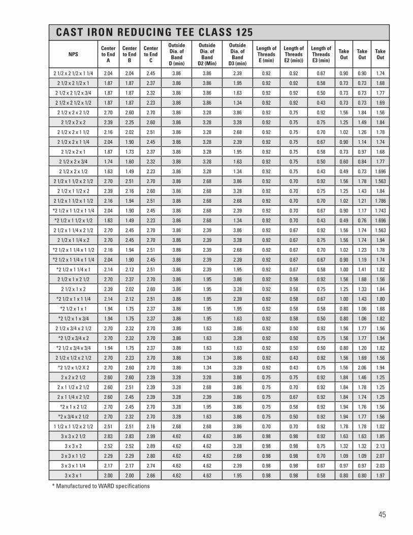
CAST IRON REDUCING TEE CLASS 125
* Manufactured to WARD specifications
2 1/2 x 2 1/2 x 1 1/4 2.04 2.04 2.45 3.86 3.86 2.39 0.92 0.92 0.67 0.90 0.90 1.74
2 1/2 x 2 1/2 x 1 1.87 1.87 2.37 3.86 3.86 1.95 0.92 0.92 0.58 0.73 0.73 1.68
2 1/2 x 2 1/2 x 3/4 1.87 1.87 2.32 3.86 3.86 1.63 0.92 0.92 0.50 0.73 0.73 1.77
2 1/2 x 2 1/2 x 1/2 1.87 1.87 2.23 3.86 3.86 1.34 0.92 0.92 0.43 0.73 0.73 1.69
2 1/2 x 2 x 2 1/2 2.70 2.60 2.70 3.86 3.28 3.86 0.92 0.75 0.92 1.56 1.84 1.56
2 1/2 x 2 x 2 2.39 2.25 2.60 3.86 3.28 3.28 0.92 0.75 0.75 1.25 1.49 1.84
2 1/2 x 2 x 1 1/2 2.16 2.02 2.51 3.86 3.28 2.68 0.92 0.75 0.70 1.02 1.26 1.78
2 1/2 x 2 x 1 1/4 2.04 1.90 2.45 3.86 3.28 2.39 0.92 0.75 0.67 0.90 1.14 1.74
2 1/2 x 2 x 1 1.87 1.73 2.37 3.86 3.28 1.95 0.92 0.75 0.58 0.73 0.97 1.68
2 1/2 x 2 x 3/4 1.74 1.60 2.32 3.86 3.28 1.63 0.92 0.75 0.50 0.60 0.84 1.77
2 1/2 x 2 x 1/2 1.63 1.49 2.23 3.86 3.28 1.34 0.92 0.75 0.43 0.49 0.73 1.696
2 1/2 x 1 1/2 x 2 1/2 2.70 2.51 2.70 3.86 2.68 3.86 0.92 0.70 0.92 1.56 1.78 1.563
2 1/2 x 1 1/2 x 2 2.39 2.16 2.60 3.86 2.68 3.28 0.92 0.70 0.75 1.25 1.43 1.84
2 1/2 x 1 1/2 x 1 1/2 2.16 1.94 2.51 3.86 2.68 2.68 0.92 0.70 0.70 1.02 1.21 1.786
*2 1/2 x 1 1/2 x 1 1/4 2.04 1.90 2.45 3.86 2.68 2.39 0.92 0.70 0.67 0.90 1.17 1.743
*2 1/2 x 1 1/2 x 1/2 1.63 1.49 2.23 3.86 2.68 1.34 0.92 0.70 0.43 0.49 0.76 1.696
2 1/2 x 1 1/4 x 2 1/2 2.70 2.45 2.70 3.86 2.39 3.86 0.92 0.67 0.92 1.56 1.74 1.563
2 1/2 x 1 1/4 x 2 2.70 2.45 2.70 3.86 2.39 3.28 0.92 0.67 0.75 1.56 1.74 1.94
*2 1/2 x 1 1/4 x 1 1/2 2.16 1.94 2.51 3.86 2.39 2.68 0.92 0.67 0.70 1.02 1.23 1.78
*2 1/2 x 1 1/4 x 1 1/4 2.04 1.90 2.45 3.86 2.39 2.39 0.92 0.67 0.67 0.90 1.19 1.74
*2 1/2 x 1 1/4 x 1 2.14 2.12 2.51 3.86 2.39 1.95 0.92 0.67 0.58 1.00 1.41 1.82
2 1/2 x 1 x 2 1/2 2.70 2.37 2.70 3.86 1.95 3.86 0.92 0.58 0.92 1.56 1.68 1.56
2 1/2 x 1 x 2 2.39 2.02 2.60 3.86 1.95 3.28 0.92 0.58 0.75 1.25 1.33 1.84
*2 1/2 x 1 x 1 1/4 2.14 2.12 2.51 3.86 1.95 2.39 0.92 0.58 0.67 1.00 1.43 1.80
*2 1/2 x 1 x 1 1.94 1.75 2.37 3.86 1.95 1.95 0.92 0.58 0.58 0.80 1.06 1.68
*2 1/2 x 1 x 3/4 1.94 1.75 2.37 3.86 1.95 1.63 0.92 0.58 0.50 0.80 1.06 1.82
2 1/2 x 3/4 x 2 1/2 2.70 2.32 2.70 3.86 1.63 3.86 0.92 0.50 0.92 1.56 1.77 1.56
*2 1/2 x 3/4 x 2 2.70 2.32 2.70 3.86 1.63 3.28 0.92 0.50 0.75 1.56 1.77 1.94
*2 1/2 x 3/4 x 3/4 1.94 1.75 2.37 3.86 1.63 1.63 0.92 0.50 0.50 0.80 1.20 1.82
2 1/2 x 1/2 x 2 1/2 2.70 2.23 2.70 3.86 1.34 3.86 0.92 0.43 0.92 1.56 1.69 1.56
*2 1/2 x 1/2 X 2 2.70 2.60 2.70 3.86 1.34 3.28 0.92 0.43 0.75 1.56 2.06 1.94
2 x 2 x 2 1/2 2.60 2.60 2.39 3.28 3.28 3.86 0.75 0.75 0.92 1.84 1.46 1.25
2 x 1 1/2 x 2 1/2 2.60 2.51 2.39 3.28 2.68 3.86 0.75 0.70 0.92 1.84 1.78 1.25
2 x 1 1/4 x 2 1/2 2.60 2.45 2.39 3.28 2.39 3.86 0.75 0.67 0.92 1.84 1.74 1.25
*2 x 1 x 2 1/2 2.70 2.45 2.70 3.28 1.95 3.86 0.75 0.58 0.92 1.94 1.76 1.56
*2 x 3/4 x 2 1/2 2.70 2.32 2.70 3.28 1.63 3.86 0.75 0.50 0.92 1.94 1.77 1.56
1 1/2 x 1 1/2 x 2 1/2 2.51 2.51 2.16 2.68 2.68 3.86 0.70 0.70 0.92 1.78 1.78 1.02
3 x 3 x 2 1/2 2.83 2.83 2.99 4.62 4.62 3.86 0.98 0.98 0.92 1.63 1.63 1.85
3 x 3 x 2 2.52 2.52 2.89 4.62 4.62 3.28 0.98 0.98 0.75 1.32 1.32 2.13
3 x 3 x 1 1/2 2.29 2.29 2.80 4.62 4.62 2.68 0.98 0.98 0.70 1.09 1.09 2.07
3 x 3 x 1 1/4 2.17 2.17 2.74 4.62 4.62 2.39 0.98 0.98 0.67 0.97 0.97 2.03
3 x 3 x 1 2.00 2.00 2.66 4.62 4.62 1.95 0.98 0.98 0.58 0.80 0.80 1.97
NPSCenterto End
A
Centerto End
B
Centerto End
C
Outside Dia. ofBand
D (min)
Outside Dia. ofBand
D2 (Min)
Outside Dia. ofBand
D3 (min)
Length of ThreadsE (min)
Length of ThreadsE2 (min))
Length of ThreadsE3 (min)
Take Out
Take Out
Take Out
45

CAST IRON REDUCING TEE CLASS 125
* Manufactured to WARD specifications
3 x 3 x 3/4 — — — — — — — — — — — —
3 x 3 x 1/2 — — — — — — — — — — — —
3 x 2 1/2 x 3 3.08 2.99 3.08 4.62 3.86 4.62 0.98 0.92 0.98 1.88 1.85 1.88
3 x 2 1/2 x 2 1/2 2.83 2.70 2.99 4.62 3.86 3.86 0.98 0.92 0.92 1.63 1.56 1.85
3 x 2 1/2 x 2 2.52 2.39 2.89 4.62 3.86 3.28 0.98 0.92 0.75 1.32 1.25 2.13
3 x 2 1/2 x 1 1/2 — — — — — — — — — — — —
3 x 2 1/2 x 1 1/4 2.17 2.04 2.74 4.62 3.86 2.39 0.98 0.92 0.67 0.97 0.90 2.03
3 x 2 1/2 x 1 — — — — — — — — — — — —
3 x 2 x 3 3.08 2.89 3.08 4.62 3.28 4.62 0.98 0.75 0.98 1.88 2.13 1.88
3 x 2 x 2 1/2 2.83 2.60 2.99 4.62 3.28 3.86 0.98 0.75 0.92 1.63 1.84 1.85
3 x 2 x 2 2.52 2.25 2.89 4.62 3.28 3.28 0.98 0.75 0.75 1.32 1.49 2.13
3 x 2 x 1 1/2 2.29 2.02 2.80 4.62 3.28 2.68 0.98 0.75 0.70 1.09 1.26 2.07
3 x 1 1/2 x 3 3.08 2.80 3.08 4.62 2.68 4.62 0.98 0.70 0.98 1.88 2.07 1.88
*3 x 1 1/2 x 2 2.52 2.25 2.89 4.62 2.68 3.28 0.98 0.70 0.75 1.32 1.52 2.13
*3 x 1 1/2 x 1 1/2 2.52 2.25 2.89 4.62 2.68 2.68 0.98 0.70 0.70 1.32 1.52 2.16
3 x 1 1/4 x 3 3.08 2.74 3.08 4.62 2.39 4.62 0.98 0.67 0.98 1.88 2.03 1.88
*3 x 1 1/4 x 2 2.52 2.70 2.89 4.62 2.39 3.28 0.98 0.67 0.75 1.32 1.99 2.13
3 x 1 x 3 3.08 2.66 3.08 4.62 1.95 4.62 0.98 0.58 0.98 1.88 1.97 1.88
*3 x 1 x 2 2.52 2.63 2.89 4.62 1.95 3.28 0.98 0.58 0.75 1.32 1.94 2.13
3 x 3/4 x 3 3.08 2.61 3.08 4.62 1.63 4.62 0.98 0.50 0.98 1.88 2.06 1.88
2 1/2 x 2 1/2 x 3 2.99 2.99 2.83 3.86 3.86 4.62 0.92 0.92 0.98 1.85 1.85 1.63
2 1/2 x 2 x 3 2.99 2.89 2.83 3.86 3.28 4.62 0.92 0.75 0.98 1.85 2.13 1.63
2 x 2 x 3 2.89 2.99 2.52 3.28 3.28 4.62 0.75 0.75 0.98 2.13 2.23 1.32
*1 1/2 x 1 1/2 x 3 2.83 2.83 2.27 2.68 2.68 4.62 0.70 0.70 0.98 2.10 2.10 1.07
3 1/2 x 3 1/2 x 3 3.18 3.18 3.33 5.20 5.20 4.62 1.03 1.03 0.98 1.93 1.93 2.13
3 1/2 x 3 1/2 x 2 1/2 2.93 2.93 3.24 5.20 5.20 3.86 1.03 1.03 0.92 1.68 1.68 2.10
3 1/2 x 3 1/2 x 2 2.62 2.62 3.14 5.20 5.20 3.28 1.03 1.03 0.75 1.37 1.37 2.38
3 1/2 x 3 1/2 x 1 1/2 2.39 2.39 3.05 5.20 5.20 2.68 1.03 1.03 0.70 1.14 1.14 2.32
3 1/2 x 3 1/2 x 1 1/4 2.27 2.27 2.99 5.20 5.20 2.39 1.03 1.03 0.67 1.02 1.02 2.28
3 1/2 x 3 1/2 x 1 2.10 2.10 2.91 5.20 5.20 1.95 1.03 1.03 0.58 0.85 0.85 2.22
*3 1/2 x 3 x 3 1/2 3.42 3.42 3.42 5.20 4.62 5.20 1.03 0.98 1.03 2.17 2.22 2.17
3 1/2 x 3 x 3 3.18 3.08 3.33 5.20 4.62 4.62 1.03 0.98 0.98 1.93 1.88 2.13
3 1/2 x 3 x 2 1/2 2.93 2.83 3.24 5.20 4.62 3.86 1.03 0.98 0.92 1.68 1.63 2.10
3 1/2 x 3 x 2 2.62 2.52 3.14 5.20 4.62 3.28 1.03 0.98 0.75 1.37 1.32 2.38
3 1/2 x 3 x 1 1/2 2.39 2.29 3.05 5.20 4.62 2.68 1.03 0.98 0.70 1.14 1.09 2.32
*3 1/2 x 3 x 1 1/4 2.39 2.29 3.05 5.20 4.62 2.39 1.03 0.98 0.67 1.14 1.09 2.34
*3 1/2 x 2 1/2 x 2 — — — — — — — — — — — —
3 1/2 x 1 1/4 x 3 1/2 3.42 2.99 3.42 5.20 2.39 5.20 1.03 0.67 1.03 2.17 2.28 2.17
3 1/2 x 1 x 3 1/2 3.42 2.91 3.42 5.20 1.95 5.20 1.03 0.58 1.03 2.17 2.22 2.17
3 x 3 x 3 1/2 3.33 3.33 3.18 4.62 4.62 5.20 0.98 0.98 1.03 2.13 2.13 1.93
4 x 4 x 3 1/2 3.54 3.54 3.69 5.79 5.79 5.20 1.08 1.08 1.03 2.24 2.24 2.44
4 x 4 x 3 3.30 3.30 3.60 5.79 5.79 4.62 1.08 1.08 0.98 2.00 2.00 2.40
NPSCenterto End
A
Centerto End
B
Centerto End
C
Outside Dia. ofBand
D (min)
Outside Dia. ofBand
D2 (Min)
Outside Dia. ofBand
D3 (min)
Length of ThreadsE (min)
Length of ThreadsE2 (min)
Length of ThreadsE3 (min)
Take Out
Take Out
Take Out
46

CAST IRON REDUCING TEE CLASS 125
* Manufactured to WARD specifications
4 x 4 x 2 1/2 3.05 3.05 3.51 5.79 5.79 3.86 1.08 1.08 0.92 1.75 1.75 2.37
4 x 4 x 2 2.74 2.74 3.41 5.79 5.79 3.28 1.08 1.08 0.75 1.44 1.44 2.65
4 x 4 x 1 1/2 2.51 2.51 3.32 5.79 5.79 2.68 1.08 1.08 0.70 1.21 1.21 2.59
4 x 4 x 1 1/4 — — — — — — — — — — — —
4 x 4 x 1 — — — — — — — — — — — —
4 x 4 x 3/4 — — — — — — — — — — — —
4 x 3 1/2 x 4 3.79 3.69 3.79 5.79 5.20 5.79 1.08 1.03 1.08 2.49 2.44 2.49
4 x 3 1/2 x 3 1/2 3.54 3.42 3.69 5.79 5.20 5.20 1.08 1.03 1.03 2.24 2.17 2.44
4 x 3 1/2 x 3 3.30 3.18 3.60 5.79 5.20 4.62 1.08 1.03 0.98 2.00 1.93 2.40
4 x 3 1/2 x 2 1/2 3.05 2.93 3.51 5.79 5.20 3.86 1.08 1.03 0.92 1.75 1.68 2.37
4 x 3 1/2 x 2 2.74 2.62 3.41 5.79 5.20 3.28 1.08 1.03 0.75 1.44 1.37 2.65
4 x 3 1/2 x 1 1/2 2.51 2.39 3.32 5.79 5.20 2.68 1.08 1.03 0.70 1.21 1.14 2.59
4 x 3 x 4 3.79 3.60 3.79 5.79 4.62 5.79 1.08 0.98 1.08 2.49 2.40 2.49
*4 x 3 x 3 1/2 3.79 3.69 3.79 5.79 4.62 5.20 1.08 0.98 1.03 2.49 2.49 2.54
4 x 3 x 3 3.30 3.08 3.60 5.79 4.62 4.62 1.08 0.98 0.98 2.00 1.88 2.40
4 x 3 x 2 1/2 3.05 2.83 3.51 5.79 4.62 3.86 1.08 0.98 0.92 1.75 1.63 2.37
4 x 3 x 2 2.74 2.52 3.41 5.79 4.62 3.28 1.08 0.98 0.75 1.44 1.32 2.65
*4 x 3 x 1 1/2 2.51 2.39 3.32 5.79 4.62 2.68 1.08 0.98 0.70 1.21 1.19 2.59
4 x 2 1/2 x 4 3.79 3.51 3.79 5.79 3.86 5.79 1.08 0.92 1.08 2.49 2.37 2.49
4 x 2 1/2 x 3 3.30 2.99 3.60 5.79 3.86 4.62 1.08 0.92 0.98 2.00 1.85 2.40
4 x 2 1/2 x 2 1/2 3.05 2.70 3.51 5.79 3.86 3.86 1.08 0.92 0.92 1.75 1.56 2.37
*4 x 2 1/2 x 2 3.05 2.70 3.51 5.79 3.86 3.28 1.08 0.92 0.75 1.75 1.56 2.75
4 x 2 x 4 3.79 3.41 3.79 5.79 3.28 5.79 1.08 0.75 1.08 2.49 2.65 2.49
*4 x 2 x 2 1/2 3.05 2.70 3.51 5.79 3.28 3.86 1.08 0.75 0.92 1.75 1.94 2.37
4 x 2 x 2 2.74 2.25 3.41 5.79 3.28 3.28 1.08 0.75 0.75 1.44 1.49 2.65
*4 x 2 x 1 1/2 2.74 2.25 3.41 5.79 3.28 2.68 1.08 0.75 0.70 1.44 1.49 2.68
4 x 1 1/2 x 4 3.79 3.32 3.79 5.79 2.68 5.79 1.08 0.70 1.08 2.49 2.59 2.49
*4 x 1 1/2 x 2 2.74 2.25 3.41 5.79 2.68 3.28 1.08 0.70 0.75 1.44 1.52 2.65
*4 x 1 1/2 x 1 1/2 2.74 2.25 3.41 5.79 2.68 2.68 1.08 0.70 0.70 1.44 1.52 2.68
4 x 1 1/4 x 4 3.79 3.26 3.79 5.79 2.39 5.79 1.08 0.67 1.08 2.49 2.55 2.49
4 x 1 x 4 3.79 3.18 3.79 5.79 1.95 5.79 1.08 0.58 1.08 2.49 2.49 2.49
3 1/2 x 3 1/2 x 4 3.69 3.69 3.54 5.20 5.20 5.79 1.03 1.03 1.08 2.44 2.44 2.24
3 x 3 x 4 — — — — — — — — — — — —
5 x 5 x 4 — — — — — — — — — — — —
5 x 5 x 3 — — — — — — — — — — — —
5 x 5 x 2 1/2 — — — — — — — — — — — —
5 x 5 x 2 — — — — — — — — — — — —
6 x 6 x 5 — — — — — — — — — — — —
6 x 6 x 4 — — — — — — — — — — — —
6 x 6 x 3 — — — — — — — — — — — —
NPSCenterto End
A
Centerto End
B
Centerto End
C
Outside Dia. ofBand
D (min)
Outside Dia. ofBand
D2 (Min)
Outside Dia. ofBand
D3 (min)
Length of ThreadsE (min)
Length of ThreadsE2 (min)
Length of ThreadsE3 (min)
Take Out
Take Out
Take Out
47
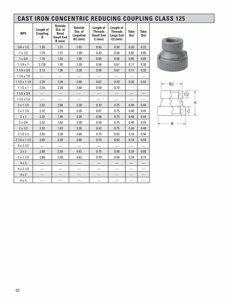
CAST IRON CONCENTRIC REDUCING COUPLING CLASS 125
NPSLength of Coupling
A
Outside Dia. of Band
Small End B (min)
OutsideDia. of
LargeEnd B2 (min)
Length of Threads
Small End C (min)
Length of Threads
Large End C2 (min)
Take Out
Take Out
3/4 x 1/2 1.50 1.31 1.62 0.43 0.50 0.20 0.22
1 x 1/2 1.70 1.31 1.99 0.43 0.58 0.85 0.85
1 x 3/4 1.70 1.63 1.99 0.50 0.58 0.85 0.85
1 1/4 x 1 2.130 1.95 2.39 0.58 0.67 0.17 0.30
1 1/4 x 3/4 2.13 1.95 2.39 0.50 0.67 0.17 0.32
1 1/4 x 1/2 — — — — — — —
1 1/2 x 1 1/4 2.25 2.39 2.68 0.67 0.70 0.36 0.52
1 1/2 x 1 2.25 2.39 2.68 0.58 0.70
1 1/2 x 3/4 — — — — — — —
1 1/2 x 1/2 — — — — — — —
2 x 1 1/2 2.32 2.68 3.28 0.70 0.75 0.40 0.44
2 x 1 1/4 2.32 2.39 3.28 0.67 0.75 0.40 0.45
2 x 1 2.32 1.95 3.28 0.58 0.75 0.40 0.44
2 x 3/4 2.32 1.63 3.28 0.50 0.75 0.40 0.45
2 x 1/2 2.32 1.63 3.28 0.43 0.75 0.40 0.48
2 1/2 x 2 2.63 3.28 3.86 0.75 0.92 0.18 0.56
2 1/2 x 1 1/2 2.63 3.28 3.86 0.70 0.92 0.18 0.59
3 x 2 1/2 — — — — — — —
3 x 2 2.88 3.28 4.62 0.75 0.98 0.29 0.68
3 x 1 1/2 2.88 3.28 4.62 0.70 0.98 0.24 0.72
4 x 3 — — — — — — —
4 x 2 1/2 — — — — — — —
4 x 2 — — — — — — —
6 x 4 — — — — — — —
�����������������
B2
C2
C
A
B
48
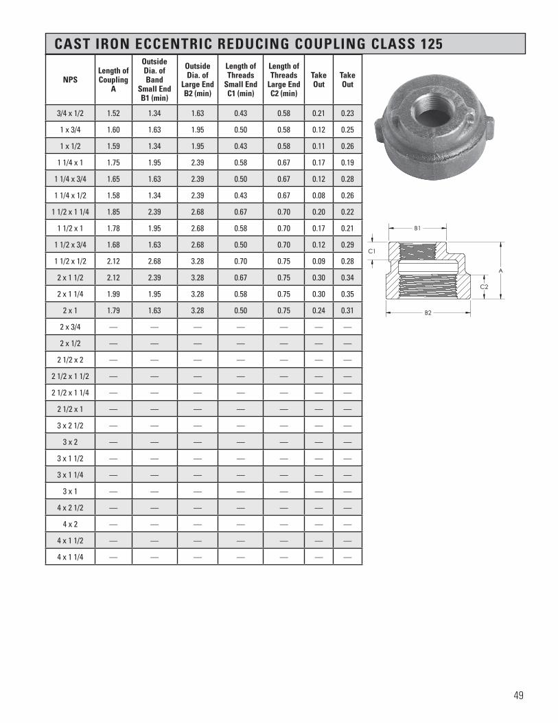
CAST IRON ECCENTRIC REDUCING COUPLING CLASS 125
NPSLength of Coupling
A
Outside Dia. of Band
Small End B1 (min)
OutsideDia. of
Large End B2 (min)
Length of Threads
Small End C1 (min)
Length of Threads
Large End C2 (min)
Take Out
Take Out
3/4 x 1/2 1.52 1.34 1.63 0.43 0.58 0.21 0.23
1 x 3/4 1.60 1.63 1.95 0.50 0.58 0.12 0.25
1 x 1/2 1.59 1.34 1.95 0.43 0.58 0.11 0.26
1 1/4 x 1 1.75 1.95 2.39 0.58 0.67 0.17 0.19
1 1/4 x 3/4 1.65 1.63 2.39 0.50 0.67 0.12 0.28
1 1/4 x 1/2 1.58 1.34 2.39 0.43 0.67 0.08 0.26
1 1/2 x 1 1/4 1.85 2.39 2.68 0.67 0.70 0.20 0.22
1 1/2 x 1 1.78 1.95 2.68 0.58 0.70 0.17 0.21
1 1/2 x 3/4 1.68 1.63 2.68 0.50 0.70 0.12 0.29
1 1/2 x 1/2 2.12 2.68 3.28 0.70 0.75 0.09 0.28
2 x 1 1/2 2.12 2.39 3.28 0.67 0.75 0.30 0.34
2 x 1 1/4 1.99 1.95 3.28 0.58 0.75 0.30 0.35
2 x 1 1.79 1.63 3.28 0.50 0.75 0.24 0.31
2 x 3/4 — — — — — — —
2 x 1/2 — — — — — — —
2 1/2 x 2 — — — — — — —
2 1/2 x 1 1/2 — — — — — — —
2 1/2 x 1 1/4 — — — — — — —
2 1/2 x 1 — — — — — — —
3 x 2 1/2 — — — — — — —
3 x 2 — — — — — — —
3 x 1 1/2 — — — — — — —
3 x 1 1/4 — — — — — — —
3 x 1 — — — — — — —
4 x 2 1/2 — — — — — — —
4 x 2 — — — — — — —
4 x 1 1/2 — — — — — — —
4 x 1 1/4 — — — — — — —
H H
B1
A
B2
C2
C1
SECTION H-H
Section 6 Page 46Cast Iron Reducing Coupling, Class 125
X.BERAll information contained within this document is intended for the sole use of Ward Manufacturingand may not be released, used, copied, or distributed without the express written permission of ...
WARD MANUFACTURING LLCBLOSSBURG, PA. 16912, USA
(570) 638-2131
TITLE:
MATERIAL:
DRAWN BY:
SHEET:
DATE: CHECKED BY: DATE:
SCALE: SIZE: SMARTEAM I.D.:
DATE DESCRIPTION APR
PART NO.:
REV.
XX-XXXXXXXXX
E.C.O. #
NEW SOLIDWORKS DRAWING01 XXX
ANGULARITY: ±1
SURFACE FINISH:63
±.031 FOR THE FIRST INCH,AND AN ADDITIONAL ±.005
FOR EACH ADDITIONAL INCH
DECIMAL PLACE:.X ±.03.XX ±.01.XXX ±.005
AS-CAST SURFACES MACHINED SURFACESUN THREADS - EXTERNAL: CLASS 2A, INTERNAL: CLASS 2B
TOLERANCES AND SPECIFICATIONSUNLESS OTHERWISE NOTED:
THIS IS A CAD DRAWING,DO NOT ADD HAND WRITTEN EDITS
XX/XX/XX
ECCENTRIC REDUCING COUPLING (CHARTED) CLASS 125
X.BERCast Iron ASTM A126
1 OF 1 B
ALL DIMENSIONS ARE IN INCHES UNLESS OTHERWISE NOTEDDRAWN IN ACCORDANCE WITH ASME Y14.5
BREAK ALL SHARP CORNERS AND REMOVE ALL BURRSDRAFT ANGLE IS 2° UNLESS NOTED OTHERWISE
THREADS:
REV.
49

CAST IRON PIPE CAP CLASS 125
CAST IRON HEXAGON COUPLING
NPSOverallHeight
A
OutsideDia. ofBand
B (min)
Length ofThreadsC (min)
2 1/2 1.810 3.860 0.920
3 1.910 4.620 0.980
3 1/2 2.030 5.200 1.030
4 2.220 5.790 1.080
5 2.380 7.050 1.180
6 2.630 8.280 1.280
8 2.880 10.630 1.470
NPS
Width Across
FlatsA HEX.
Overall Length
B
Thread Length
C
Take Out
Take Out
1 1.94 1.69 0.58 0.16 0.16
�����������������
AC
B
50

CAST IRON STRAIGHT CROSS CLASS 125
CAST IRON REDUCING CROSS CLASS 125
NPSCenterto End
A
OutsideDia.
BandB (min)
Length of ThreadsC (min)
Take Out
1/2 1.25 1.34 0.43 0.71
3/4 1.44 1.63 0.50 0.89
1 1.63 1.95 0.58 0.94
1 1/4 1.94 2.39 0.67 1.23
1 1/2 2.13 2.68 0.70 1.40
2 — — — —
4 — — — —
NPSCenterto End
A
Centerto End
A2
OutsideDia. Band
B (min)
OutsideDia. BandB2 (min)
Length of ThreadsC (min)
Length of ThreadsC2 (min)
Take Out
Take Out
1 1/4 x 1 1.67 1.58 2.39 1.95 0.67 0.58 0.96 0.89
1 1/2 x 1 1/4 — — — — — — — —
1 1/2 x 1 1/4 x 1 — — — — — — — —
1 1/2 x 1 1/4 x 1 x 1 — — — — — — — —
1 1/2 x 1 1.80 1.65 2.68 1.95 0.70 0.58 1.07 0.96
1 1/2 x 1 x 1 x 1 — — — — — — — —
2 x 1 1/2 — — — — — — — —
2 x 1 1/4 — — — — — — — —
2 x 1 1/2 x 1 x 1 — — — — — — — —
2 x 1 2.02 1.73 3.28 1.95 0.75 0.58 1.26 1.04
�����������������
A
A
AA
C
B
H H
B2
A2
A2
C2
A A
B
C
SECTION H-H SCALE 1 : 1
Section 6 Page 47Cast Iron Cross, Class 125
X.BCCR
All information contained within this document is intended for the sole use of Ward Manufacturingand may not be released, used, copied, or distributed without the express written permission of ...
WARD MANUFACTURING LLCBLOSSBURG, PA. 16912, USA
(570) 638-2131
TITLE:
MATERIAL:
DRAWN BY:
SHEET:
DATE: CHECKED BY: DATE:
SCALE: SIZE: SMARTEAM I.D.:
DATE DESCRIPTION APR
PART NO.:
REV.
XX-XXXXXXXXX
E.C.O. #
NEW SOLIDWORKS DRAWING01 XXX
ANGULARITY: ±1
SURFACE FINISH:63
±.031 FOR THE FIRST INCH,AND AN ADDITIONAL ±.005
FOR EACH ADDITIONAL INCH
DECIMAL PLACE:.X ±.03.XX ±.01.XXX ±.005
AS-CAST SURFACES MACHINED SURFACESUN THREADS - EXTERNAL: CLASS 2A, INTERNAL: CLASS 2B
TOLERANCES AND SPECIFICATIONSUNLESS OTHERWISE NOTED:
THIS IS A CAD DRAWING,DO NOT ADD HAND WRITTEN EDITS
XX/XX/XX
C.I. CROSS, CLASS 125, CHARTED
1B.BCCRCast Iron ASTM A126
1 OF 1 B
ALL DIMENSIONS ARE IN INCHES UNLESS OTHERWISE NOTEDDRAWN IN ACCORDANCE WITH ASME Y14.5
BREAK ALL SHARP CORNERS AND REMOVE ALL BURRSDRAFT ANGLE IS 2° UNLESS NOTED OTHERWISE
THREADS:
REV.
51
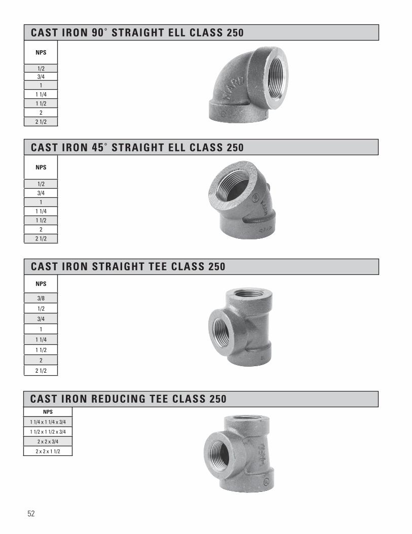
CAST IRON 90˚ STRAIGHT ELL CLASS 250
NPS
1/23/41
1 1/41 1/2
22 1/2
CAST IRON 45˚ STRAIGHT ELL CLASS 250
NPS
1/23/41
1 1/41 1/2
22 1/2
NPS
3/8
1/2
3/4
1
1 1/4
1 1/2
2
2 1/2
CAST IRON STRAIGHT TEE CLASS 250
NPS
CAST IRON REDUCING TEE CLASS 250
1 1/4 x 1 1/4 x 3/4
1 1/2 x 1 1/2 x 3/4
2 x 2 x 3/4
2 x 2 x 1 1/2
52

SECTION 7 FLANGES, FLANGE UNIONS, COMPANION FLANGES, FLANGED FITTINGS
Material: ASTM A126
Dimensions: ANSI / ASME B16.1 ANSI / ASME B1.20.1 Pressure ANSI/ASME B16.1 Ratings:
Coatings: ASTM A153 ASTM B633
Additional UL, ULC AND FM, where applicable Specifications:
Metalfit flanged fitting made in North America.
NPS Dia. of Flange
Thickness of Flange
(min)
Dia. of Hub
(min)
Length of Hub
andThreads
(min)
Dia. of Port
Wall Thickness
Dia. of Bolt
Circle
Dia. of Bolt
Holes
Number of Bolts
Dia. ofBolts
Length of Bolts
1 4.25 0.44 1.94 0.69 1.00 0.38 3.12 0.62 4 0.50 2.00
1 1/4 4.62 0.50 2.31 0.81 1.25 0.44 3.50 0.62 4 0.50 2.00
1 1/2 5.00 0.56 2.56 0.88 1.50 0.50 3.88 0.62 4 0.50 2.00
2 6.00 0.62 3.06 1.00 2.00 0.56 4.75 0.75 4 0.62 2.50
2 1/2 7.00 0.69 3.56 1.12 2.50 0.63 5.50 0.75 4 0.62 2.50
3 7.50 0.75 4.25 1.19 3.00 0.69 6.00 0.75 4 0.62 2.50
3 1/2 8.50 0.81 4.81 1.25 3.50 0.75 7.00 0.75 8 0.62 3.00
4 9.00 0.94 5.31 1.31 4.00 0.88 7.50 0.75 8 0.62 3.00
5 10.00 0.94 6.44 1.44 5.00 0.88 8.50 0.88 8 0.75 3.00
6 11.00 1.00 7.56 1.56 6.00 0.94 9.50 0.88 8 0.75 3.50
8 13.50 1.12 9.96 1.75 8.00 1.06 11.75 0.88 8 0.75 3.50
10 16.00 1.19 11.94 1.94 10.00 1.12 14.25 1.00 12 0.88 4.00
12 19.00 1.25 14.06 2.19 12.00 0.81 17.00 1.00 12 0.88 4.00
WARD flange components are made with high quality iron and are designed to handle the tough service that flange components normally experience. Precision machining and thread chamfering allow WARD flange components to be easily installed. Most importantly, quality is built into the design, material and manufacturing of each of WARD’s flange components.
Cast Iron flanges may have either a black or galvanized finish.
FLANGES HUB BLIND BOLT BOLTING FLANGES HOLES
53

CAST IRON FLANGE UNION CLASS 125 *WORKING PRESSURE 175 PSI
NPS
OutsideFlange
Dia. A
Overall HeightB (min)
Dia. of Hub
C (min)
Thickness of Flange D (min)
Number of Bolt Holes
Bolt Hole Size
Bolt Circle Dia.
Dia. of Bolts
Length ofBolts
*1/2 2.81 0.62 1.31 0.43 3 0.44 1.69 0.44 1.75
*3/4 3.43 0.75 1.75 0.43 3 0.50 2.31 0.44 1.75
*1 3.50 0.75 1.88 0.43 3 0.50 2.50 0.44 1.75
*1 1/4 4.06 0.75 2.25 0.43 4 0.50 3.00 0.44 1.75
*1 1/2 4.37 0.81 2.5 0.43 4 0.50 3.38 0.44 1.75
*2 5.12 1.00 3.13 0.50 4 0.56 4.06 0.50 2.25
*2 1/2 6.62 1.25 3.56 0.62 4 0.69 4.63 0.63 2.75
*3 6.68 1.25 4.25 0.62 4 0.69 5.38 0.63 2.50
*3 1/2 7.25 1.25 4.75 0.62 4 0.69 5.88 0.63 2.50
*4 7.81 1.37 4.94 0.68 5 0.69 6.56 0.63 2.50
*5 9.43 1.43 6.69 0.75 5 0.69 8.06 0.63 2.75
*6 10.56 1.50 7.31 1.00 6 0.69 9.06 0.63 2.75
*8 13.50 1.75 9.25 1.18 7 0.88 11.88 0.75 3.75
* Manufactured to WARD specifications
H H
D
A
B
C
SECTION H-H
Section 7 Page 51Cast Iron Flange Union, Class 125
X.BFU
All information contained within this document is intended for the sole use of Ward Manufacturingand may not be released, used, copied, or distributed without the express written permission of ...
WARD MANUFACTURING LLCBLOSSBURG, PA. 16912, USA
(570) 638-2131
TITLE:
MATERIAL:
DRAWN BY:
SHEET:
DATE: CHECKED BY: DATE:
SCALE: SIZE: SMARTEAM I.D.:
DATE DESCRIPTION APR
PART NO.:
REV.
XX-XXXXXXXXX
E.C.O. #
NEW SOLIDWORKS DRAWING01 XXX
ANGULARITY: ±1
SURFACE FINISH:63
±.031 FOR THE FIRST INCH,AND AN ADDITIONAL ±.005
FOR EACH ADDITIONAL INCH
DECIMAL PLACE:.X ±.03.XX ±.01.XXX ±.005
AS-CAST SURFACES MACHINED SURFACESUN THREADS - EXTERNAL: CLASS 2A, INTERNAL: CLASS 2B
TOLERANCES AND SPECIFICATIONSUNLESS OTHERWISE NOTED:
THIS IS A CAD DRAWING,DO NOT ADD HAND WRITTEN EDITS
XX/XX/XX
1 OF 1 B
ALL DIMENSIONS ARE IN INCHES UNLESS OTHERWISE NOTEDDRAWN IN ACCORDANCE WITH ASME Y14.5
BREAK ALL SHARP CORNERS AND REMOVE ALL BURRSDRAFT ANGLE IS 2° UNLESS NOTED OTHERWISE
THREADS:
REV.
54
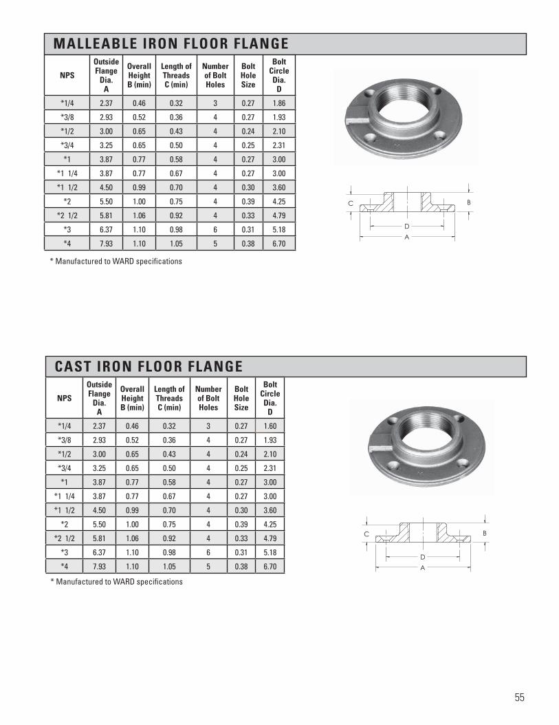
MALLEABLE IRON FLOOR FLANGE
CAST IRON FLOOR FLANGE
* Manufactured to WARD specifications
* Manufactured to WARD specifications
NPS
OutsideFlange
Dia. A
Overall HeightB (min)
Length of Threads C (min)
Number of Bolt Holes
Bolt Hole Size
Bolt Circle Dia.
D
*1/4 2.37 0.46 0.32 3 0.27 1.86
*3/8 2.93 0.52 0.36 4 0.27 1.93
*1/2 3.00 0.65 0.43 4 0.24 2.10
*3/4 3.25 0.65 0.50 4 0.25 2.31
*1 3.87 0.77 0.58 4 0.27 3.00
*1 1/4 3.87 0.77 0.67 4 0.27 3.00
*1 1/2 4.50 0.99 0.70 4 0.30 3.60
*2 5.50 1.00 0.75 4 0.39 4.25
*2 1/2 5.81 1.06 0.92 4 0.33 4.79
*3 6.37 1.10 0.98 6 0.31 5.18
*4 7.93 1.10 1.05 5 0.38 6.70
NPS
OutsideFlange
Dia. A
Overall HeightB (min)
Length of Threads C (min)
Number of Bolt Holes
Bolt Hole Size
Bolt Circle Dia.
D
*1/4 2.37 0.46 0.32 3 0.27 1.60
*3/8 2.93 0.52 0.36 4 0.27 1.93
*1/2 3.00 0.65 0.43 4 0.24 2.10
*3/4 3.25 0.65 0.50 4 0.25 2.31
*1 3.87 0.77 0.58 4 0.27 3.00
*1 1/4 3.87 0.77 0.67 4 0.27 3.00
*1 1/2 4.50 0.99 0.70 4 0.30 3.60
*2 5.50 1.00 0.75 4 0.39 4.25
*2 1/2 5.81 1.06 0.92 4 0.33 4.79
*3 6.37 1.10 0.98 6 0.31 5.18
*4 7.93 1.10 1.05 5 0.38 6.70
55

CAST IRON BLIND FLANGE
CAST IRON EXTRA HEAVY FLANGE UNION CLASS 250
NPS
OutsideFlange
Dia. A
Thickness of Flange D (min)
Number of Bolt Holes
Bolt Hole Size
Bolt Circle Dia.
Dia. of Port
D
1 4.25 0.44 4 0.62 3.12 1.00
1 1/4 4.62 0.50 4 0.62 3.50 1.25
1 1/2 5.00 0.56 4 0.62 3.88 1.50
2 6.00 0.62 4 0.75 4.75 2.00
2 1/2 7.00 0.69 4 0.75 5.50 2.50
3 7.50 0.75 4 0.75 6.00 3.00
3 1/2 8.50 0.81 8 0.75 7.00 3.50
4 9.00 0.94 8 0.75 7.50 4.00
5 10.0 0.94 8 0.88 8.50 5.00
6 11.0 1.00 8 0.88 9.50 6.00
8 13.5 1.12 8 0.88 11.75 8.00
10 16.0 1.19 12 1.00 14.25 10.00
NPS
OutsideFlange
Dia. A
Overall HeightB (min)
Dia. of Hub
C (min)
Thickness of Flange D (min)
Number of Bolt Holes
Bolt Hole Size
Bolt Circle Dia.
Dia. of Bolts
Lengthof Bolts
*2 5.50 1.06 3.25 0.81 5 0.56 4.50 0.50 2.50
*2 1/2 6.00 1.06 3.81 0.81 5 0.66 4.75 0.63 2.75
*3 6.81 1.18 4.38 0.81 6 0.69 5.35 0.63 2.75
*4 8.18 1.25 5.44 0.75 7 0.69 6.38 0.63 3.00
�����������������
A
B
DC
H H
D
A
B
C
SECTION H-H
Section 7 Page 53Cast Iron Extra Heavy Union Class 250
X.BHFU
All information contained within this document is intended for the sole use of Ward Manufacturingand may not be released, used, copied, or distributed without the express written permission of ...
WARD MANUFACTURING LLCBLOSSBURG, PA. 16912, USA
(570) 638-2131
TITLE:
MATERIAL:
DRAWN BY:
SHEET:
DATE: CHECKED BY: DATE:
SCALE: SIZE: SMARTEAM I.D.:
DATE DESCRIPTION APR
PART NO.:
REV.
XX-XXXXXXXXX
E.C.O. #
NEW SOLIDWORKS DRAWING01 XXX
ANGULARITY: ±1
SURFACE FINISH:63
±.031 FOR THE FIRST INCH,AND AN ADDITIONAL ±.005
FOR EACH ADDITIONAL INCH
DECIMAL PLACE:.X ±.03.XX ±.01.XXX ±.005
AS-CAST SURFACES MACHINED SURFACESUN THREADS - EXTERNAL: CLASS 2A, INTERNAL: CLASS 2B
TOLERANCES AND SPECIFICATIONSUNLESS OTHERWISE NOTED:
THIS IS A CAD DRAWING,DO NOT ADD HAND WRITTEN EDITS
XX/XX/XX
1 OF 1 B
ALL DIMENSIONS ARE IN INCHES UNLESS OTHERWISE NOTEDDRAWN IN ACCORDANCE WITH ASME Y14.5
BREAK ALL SHARP CORNERS AND REMOVE ALL BURRSDRAFT ANGLE IS 2° UNLESS NOTED OTHERWISE
THREADS:
REV.
*Working Pressure 400 PSI
56
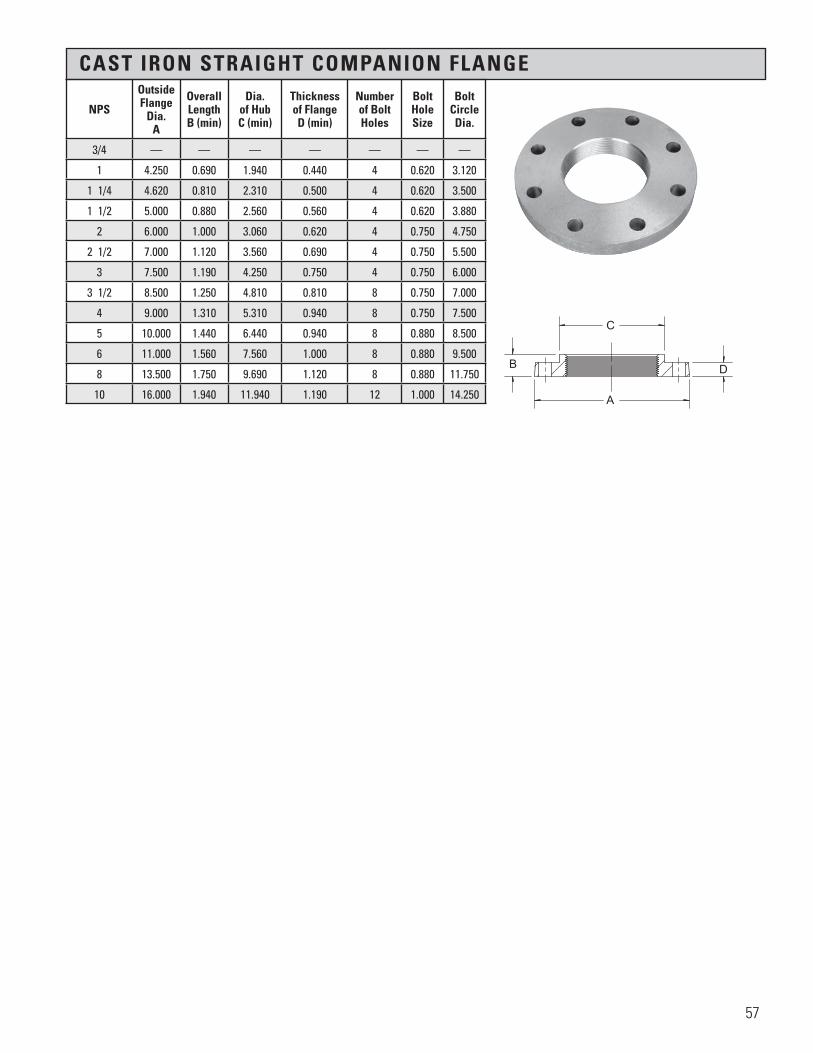
CAST IRON STRAIGHT COMPANION FLANGE
NPS
OutsideFlange
Dia. A
Overall LengthB (min)
Dia. of Hub C (min)
Thickness of Flange D (min)
Number of Bolt Holes
Bolt Hole Size
Bolt Circle Dia.
3/4 — — — — — — —
1 4.250 0.690 1.940 0.440 4 0.620 3.120
1 1/4 4.620 0.810 2.310 0.500 4 0.620 3.500
1 1/2 5.000 0.880 2.560 0.560 4 0.620 3.880
2 6.000 1.000 3.060 0.620 4 0.750 4.750
2 1/2 7.000 1.120 3.560 0.690 4 0.750 5.500
3 7.500 1.190 4.250 0.750 4 0.750 6.000
3 1/2 8.500 1.250 4.810 0.810 8 0.750 7.000
4 9.000 1.310 5.310 0.940 8 0.750 7.500
5 10.000 1.440 6.440 0.940 8 0.880 8.500
6 11.000 1.560 7.560 1.000 8 0.880 9.500
8 13.500 1.750 9.690 1.120 8 0.880 11.750
10 16.000 1.940 11.940 1.190 12 1.000 14.250
�����������������
C
D
A
B
57

CAST IRON REDUCING COMPANION FLANGE
NPS
OutsideFlange
Dia. A
Overall HeightB (min)
Dia. of Hub C (min)
Thickness of Flange D (min)
Number of Bolt Holes
Bolt Hole Size
Bolt Circle Dia.
3/4 x 1 1/2 5.00 0.69 1.94 0.56 4 0.62 3.881 x 1 1/2 5.00 0.69 1.94 0.56 4 0.62 3.88
1 x 2 6.00 0.69 1.94 0.62 4 0.75 4.751 x 3 7.50 0.69 1.93 0.75 4 0.75 6.00
1 1/4 x 2 6.00 0.81 2.31 0.62 4 0.75 4.75
1 1/4 x 3 7.50 0.81 2.31 0.75 4 0.75 6.001 1/2 x 2 6.00 0.88 2.56 0.62 4 0.75 4.75
1 1/2 x 2 1/2 7.00 0.88 2.56 0.69 4 0.75 5.501 1/2 x 3 7.50 0.88 2.56 0.75 4 0.75 6.001 1/2 x 4 9.00 0.88 2.56 0.94 8 0.75 7.501 1/2 x 6 11.00 0.88 2.56 1.00 8 0.88 9.502 x 2 1/2 7.00 1.00 3.06 0.69 4 0.75 5.50
2 x 3 7.50 1.00 3.06 0.75 4 0.75 6.002 x 4 9.00 1.00 3.06 0.94 8 0.75 7.502 x 5 10.00 1.00 3.06 0.94 8 0.88 8.502 x 6 11.00 1.00 3.06 1.00 8 0.88 9.502 x 8 13.50 1.00 3.06 1.12 8 0.88 11.75
2 1/2 x 3 7.50 1.12 3.56 0.75 4 0.75 6.002 1/2 x 4 9.00 1.12 3.56 0.94 8 0.75 7.502 1/2 x 5 10.00 1.12 3.56 0.94 8 0.88 8.502 1/2 x 6 11.00 1.12 3.56 1.00 8 0.88 9.503 x 3 1/2 8.50 1.19 4.25 0.81 8 0.75 7.00
3 x 4 9.00 1.19 4.25 0.94 8 0.75 7.503 x 5 10.00 1.19 4.25 0.94 8 0.88 8.503 x 6 11.00 1.19 4.25 1.00 8 0.88 9.503 x 8 13.50 1.19 4.25 1.12 8 0.88 11.75
3 1/2 x 4 9.00 1.25 4.81 0.94 8 0.75 7.504 x 5 10.00 1.31 5.31 0.94 8 0.88 8.505 x 6 11.00 1.44 6.44 1.00 8 0.88 9.505 x 8 13.50 1.44 6.44 1.12 8 0.88 11.756 x 8 13.50 1.56 7.56 1.12 8 0.88 11.75
����
����
����
����
�A
C
B D
58

CAST IRON FLANGED STRAIGHT 90˚ELL CLASS 125
�����������������
A
B
D
A
C
NPSCenter
to FaceA
Outside Flange
Dia.B
Thicknessof Flange
C (min)
WallThickness
D
2 4.500 6.000 0.620 0.310 2 1/2 5.000 7.000 0.690 0.310
3 5.500 7.500 0.750 0.380 4 6.500 9.000 0.940 0.500 5 7.500 10.000 0.940 0.500 6 8.000 11.000 1.000 0.560 8 9.000 13.500 1.120 0.620
10 11.000 16.000 1.190 0.750 12 12.000 19.000 1.250 0.810
Numberof Bolt Holes
BoltHoleSize
BoltCircleDia.
Dia. of Bolts
Length of Bolts
4 0.75 4.75 5/8 2 1/44 0.75 5.50 5/8 2 1/24 0.75 6.00 5/8 2 1/28 0.75 7.50 5/8 38 0.88 8.50 3/4 38 0.88 9.50 3/4 3 1/48 0.88 11.75 3/4 3 1/212 1.00 14.25 7/8 3 3/412 1.00 17.00 7/8 3 3/4
Metalfit flanged straight ell made in North America.
59

CAST IRON FLANGED REDUCING 90˚ ELL CLASS 125
����
����
����
����
�
C2D2
D
B
AC
A
B2
NPSCenter
to FaceA
Outside Flange
Dia.B
OutsideFlange
Dia.B2
Thicknessof Flange
C (min)
Thicknessof FlangeC2 (min)
WallThickness
D
WallThickness
D2
3 x 2 1/2 5.500 7.500 7.000 0.750 0.690 0.380 0.310
3 x 2 5.500 7.500 6.000 0.750 0.620 0.380 0.310
4 x 3 6.500 9.000 7.500 0.940 0.750 0.500 0.380
4 x 2 1/2 6.500 9.000 7.000 0.940 0.690 0.500 0.310
4 x 2 6.500 9.000 6.000 0.940 0.620 0.500 0.310
5 x 4 8.000 10.000 9.000 0.940 0.940 0.500 0.500
6 x 5 8.000 11.000 10.000 1.000 0.940 0.560 0.500
6 x 4 8.000 11.000 9.000 1.000 0.940 0.560 0.500
6 x 3 8.000 11.000 7.500 1.000 0.750 0.560 0.380
6 x 2 1/2 8.000 11.000 7.000 1.000 0.690 0.560 0.310
8 x 6 9.000 13.500 11.000 1.120 1.000 0.620 0.560
8 x 5 9.000 13.500 10.000 1.120 0.940 0.620 0.500
8 x 4 9.000 13.500 9.000 1.120 0.940 0.620 0.500
10 x 8 11.000 16.000 13.500 1.190 1.120 0.750 0.620
10 x 6 11.000 16.000 11.000 1.190 1.000 0.750 0.560
12 x 10 12.000 19.000 16.000 1.250 1.190 0.810 0.750
12 x 8 12.000 19.000 13.500 1.250 1.120 0.810 0.620
12 x 6 12.000 19.000 11.000 1.250 1.000 0.810 0.560
Metalfit flanged reducing ell made in North America.
60

CAST IRON FLANGED 90˚ STRAIGHT ELL LONG RADIUS CLASS 125
CAST IRON FLANGED 90˚ REDUCING ELL LONG RADIUS CLASS 125
NPSCenter
to FaceA
Outside Flange
Dia.B
Thicknessof Flange
C (min)
WallThickness
D
Numberof Bolt Holes
Bolt Hole Size
Bolt Circle Dia.
Dia. of Bolts
Length of Bolts
2 6.500 6.000 0.620 0.310 4 0.75 4.75 5/8 2 1/4
2 1/2 7.000 7.000 0.690 0.310 4 0.75 5.50 5/8 2 1/2
3 7.750 7.500 0.750 0.380 4 0.75 6.00 5/8 2 1/2
4 9.000 9.000 0.940 0.500 8 0.75 7.50 5/8 3
6 11.500 11.000 1.000 0.560 8 0.88 9.50 3/4 3 1/3
8 14.000 13.500 1.120 0.620 8 0.88 11.75 3/4 3 1/2
10 16.500 16.000 1.190 0.750 12 1.00 14.25 7/8 3 3/4
12 19.000 19.000 1.250 0.810 12 1.00 17.00 7/8 3 3/4
NPSCenter
to FaceA
Outside Flange
Dia.B
OutsideFlange
Dia.B2
Thicknessof Flange
C (min)
Thicknessof FlangeC2 (min)
WallThickness
D
WallThickness
D2
4 x 3 9.000 9.000 7.500 0.940 0.750 0.500 0.380
6 x 4 11.500 11.000 9.000 1.000 0.940 0.560 0.500
8 x 6 14.000 13.500 11.000 1.120 1.000 0.620 0.560
Metalfit flanged straight ell made in North America.
Metalfit flanged reducing ell made in North America.
����
��������
����
�
C
B
A
A
B2
C2
D2
D ����
����
����
����
�
CD
B
A
A
61

CAST IRON FLANGED 11 1/4˚ STRAIGHT ELL CLASS 125
CAST IRON FLANGED 45˚ STRAIGHT ELL CLASS 125
�����������������
B
A
A
C
D
NPSCenter
to FaceA
Outside Flange
Dia.B
Thicknessof Flange
C (min)
WallThickness
D
Numberof Bolt Holes
BoltHoleSize
BoltCircleDia.
Dia. of Bolts
Length of Bolts
2 2.500 6.000 0.620 0.310 4 0.75 4.75 5/8 2 1/4
2 1/2 3.000 7.000 0.690 0.310 4 0.75 5.50 5/8 2 1/2
3 3.000 7.500 0.750 0.380 4 0.75 6.00 5/8 2 1/2
4 4.000 9.000 0.940 0.500 8 0.75 7.50 5/8 3
6 5.000 11.000 1.000 0.560 8 0.88 9.50 3/4 3 1/4
8 5.500 13.500 1.120 0.620 8 0.88 11.50 3/4 3 1/2
10 6.500 16.000 1.190 0.750 12 1.00 14.75 7/8 3 3/4
12 7.500 19.000 1.250 0.810 12 1.00 17.00 7/8 3 3/4
NPSCenter
to FaceA
Outside Flange
Dia.B
Thicknessof Flange
C (min)
WallThickness
D
Numberof Bolt Holes
BoltHoleSize
BoltCircleDia.
Dia. of Bolts
Length of Bolts
2 2.500 6.000 0.620 0.310 4 0.75 4.75 5/8 2 1/4
2 1/2 3.000 7.000 0.690 0.310 4 0.75 5.50 5/8 2 1/2
3 3.000 7.500 0.750 0.380 4 0.75 6.00 5/8 2 1/2
4 4.000 9.000 0.940 0.500 8 0.75 7.50 5/8 3
5 4.500 10.000 0.940 0.500 8 0.88 8.50 3/4 3
6 5.000 11.000 1.000 0.560 8 0.88 9.50 3/4 3 1/4
8 5.500 13.500 1.120 0.620 8 0.88 11.75 3/4 3 1/2
10 6.500 16.000 1.190 0.750 12 1.00 14.25 7/8 3 3/4
12 7.500 19.000 1.250 0.810 12 1.00 17.00 7/8 3 3/4
�����������������
BA
DA
C
Metalfit flanged straight ell made in North America.
Metalfit flanged straight ell made in North America.
62

CAST IRON FLANGED 22 1/2˚ STRAIGHT ELL CLASS 125
CAST IRON FLANGED STRAIGHT TEE CLASS 125
����
����
����
����
�
A
D
C
A
B
����
����
����
����
�
A A
B
C
D
A
NPSCenter
to FaceA
Outside Flange
Dia.B
Thicknessof Flange
C (min)
WallThickness
D
Numberof Bolt Holes
BoltHoleSize
BoltCircleDia.
Dia. ofBolts
Length ofBolts
2 2.500 6.000 0.620 0.310 4 0.75 4 .75 5/8 2 1/4
2 1/2 3.000 7.000 0.690 0.310 4 0.75 5.50 5/8 2 1/2
3 3.000 7.500 0.750 0.380 4 0.75 6.00 5/8 2 1/2
4 4.000 9.000 0.940 0.500 8 0.75 7.50 5/8 3
6 5.000 11.000 1.000 0.560 8 0.88 9.50 3/4 3 1/4
8 5.500 13.500 1.120 0.620 8 0.88 11.75 3/4 3 1/210 6.500 16.000 1.190 0.750 12 1.00 14.25 7/8 3 3/4
12 7.500 19.000 1.250 0.810 12 1.00 17.00 7/8 3 3/4
NPSCenter
to FaceA
Outside Flange
Dia.B
Thicknessof Flange
C (min)
WallThickness
D
Numberof Bolt Holes
BoltHoleSize
BoltCircleDia.
Dia ofBolts
Length ofBolts
2 4.500 6.000 0.620 0.310 4 0.75 4.75 5/8 2 1/4
2 1/2 5.000 7.000 0.690 0.310 4 0.75 5.50 5/8 2 1/2
3 5.500 7.500 0.750 0.380 4 0.75 6.00 5/8 2 1/2
4 6.500 9.000 0.940 0.500 8 0.75 7.50 5/8 3
5 7.500 10.000 0.940 0.500 8 0.88 8.50 3/4 3
6 8.000 11.000 1.000 0.560 8 0.88 9.50 3/4 3 1/4
8 9.000 13.500 1.120 0.620 8 0.88 11.75 3/4 3 1/2
10 11.000 16.000 1.190 0.750 12 1.00 14.25 7/8 3 3/4
12 12.000 19.000 1.250 0.810 12 1.00 17.00 7/8 3 3/4
Metalfit flanged straight ell made in North America.
Metalfit flanged straight tee made in North America.
63

CAST IRON FLANGED REDUCING TEE CLASS 125
NPSCenter
to FaceA
Outside Flange
Dia.B
OutsideFlange
Dia.B2
OutsideFlange
Dia.B3
Thicknessof Flange
C (min)
Thicknessof FlangeC2 (min)
Thicknessof FlangeC3 (min)
3 x 3 x 4 5.500 7.500 7.500 9.000 0.750 0.750 0.940
3 x 3 x 2 1/2 5.500 7.500 7.500 7.000 0.750 0.750 0.690
3 x 3 x 2 5.500 7.500 7.500 6.000 0.750 0.750 0.620
4 x 3 x 4 6.500 9.000 7.500 9.000 0.940 0.750 0.940
4 x 3 x 3 6.500 9.000 7.500 7.500 0.940 0.750 0.750
4 x 2 x 4 6.500 9.000 6.000 9.000 0.940 0.620 0.940
4 x 4 x 6 8.000 9.000 9.000 11.000 0.940 0.940 1.000
4 x 4 x 3 6.500 9.000 9.000 7.000 0.940 0.940 0.750
4 x 4 x 2 1/2 6.500 9.000 9.000 7.000 0.940 0.940 0.690
4 x 4 x 2 6.500 9.000 9.000 6.000 0.940 0.940 0.620
6 x 4 x 6 8.000 11.000 9.000 11.000 1.000 0.940 1.000
6 x 4 x 4 8.000 11.000 9.000 9.000 1.000 0.940 0.940
6 x 4 x 3 8.000 11.000 9.000 7.000 1.000 0.940 0.750
6 X 3 X 6 8.000 11.000 7.000 11.000 1.000 0.750 1.000
6 x 6 x 8 9.000 11.000 11.000 13.500 1.000 1.000 1.120
6 x 6 x 4 8.000 11.000 11.000 9.000 1.000 1.000 0.940
6 x 6 x 3 8.000 11.000 11.000 7.500 1.000 1.000 0.750
6 x 6 x 2 1/2 8.000 11.000 11.000 7.000 1.000 1.000 0.690
6 x 6 x 2 8.000 11.000 11.000 6.000 1.000 1.000 0.620
8 x 6 x 8 9.000 13.500 11.000 13.500 1.120 1.000 1.120
8 x 6 x 6 9.000 13.500 11.000 11.000 1.120 1.000 1.000
8 x 6 x 4 9.000 13.500 11.000 9.000 1.120 1.000 0.940
8 x 4 x 8 9.000 13.500 9.000 13.500 1.120 0.940 1.120
8 x 8 x 10 11.000 13.500 13.500 16.000 1.120 1.120 1.190
8 x 8 x 6 9.000 13.500 13.500 11.000 1.120 1.120 1.000
8 x 8 x 4 9.000 13.500 13.500 9.000 1.120 1.120 0.940
8 x 8 x 3 9.000 13.500 13.500 7.500 1.120 1.120 0.750
10 x 8 x 10 11.000 16.000 13.500 16.000 1.190 1.120 1.190
10 x 8 x 8 11.000 16.000 13.500 13.500 1.190 1.120 1.120
10 x 8 x 6 11.000 16.000 13.500 11.000 1.190 1.120 1.000
10 x 6 x 10 11.000 16.000 11.000 19.000 1.190 1.000 1.190
10 x 10 x 12 12.000 16.000 16.000 19.000 1.190 1.190 1.250
10 x 10 x 8 11.000 16.000 16.000 13.500 1.190 1.190 1.120
10 x 10 x 6 11.000 16.000 16.000 11.000 1.190 1.190 1.000
10 x 10 x 4 11.000 16.000 16.000 9.000 1.190 1.190 0.940
10 x10 x 3 11.000 16.000 16.000 7.000 1.190 1.190 0.750
10 x 10 x 2 1/2 11.000 16.000 16.000 7.000 1.190 1.190 0.690
12 x 10 x 12 12.000 19.000 16.000 19.000 1.250 1.190 1.250
12 x 10 x 10 12.000 19.000 16.000 16.000 1.250 1.190 1.190
12 x 12 x 10 12.000 19.000 19.000 16.000 1.250 1.250 1.190
12 x 12 x 8 12.000 19.000 19.000 13.500 1.250 1.250 1.120
12 x 12 x 6 12.000 19.000 19.000 11.000 1.250 1.250 1.000
12 x 12 x 4 12.000 19.000 19.000 9.000 1.250 1.250 0.940
12 x 12 x 3 12.000 19.000 19.000 7.000 1.250 1.250 0.750
A A
A
BB2
B3
C C2
C3
page 61X.BFTCAST IRON FLANGED REDUCING TEE CLASS 125
All information contained within this document is intended for the sole use of Ward Manufacturingand may not be released, used, copied, or distributed without the express written permission of ...
WARD MANUFACTURING LLCBLOSSBURG, PA. 16912, USA
(570) 638-2131
TITLE:
MATERIAL:
DRAWN BY:
SHEET:
DATE: CHECKED BY: DATE:
SCALE: SIZE: SMARTEAM I.D.:
DATE DESCRIPTION APR
PART NO.:
REV.
XX-XXXXXXXXX
E.C.O. #
NEW SOLIDWORKS DRAWING01 XXX
ANGULARITY: ±1
SURFACE FINISH:63
±.031 FOR THE FIRST INCH,AND AN ADDITIONAL ±.005
FOR EACH ADDITIONAL INCH
DECIMAL PLACE:.X ±.03.XX ±.01.XXX ±.005
AS-CAST SURFACES MACHINED SURFACESUN THREADS - EXTERNAL: CLASS 2A, INTERNAL: CLASS 2B
TOLERANCES AND SPECIFICATIONSUNLESS OTHERWISE NOTED:
THIS IS A CAD DRAWING,DO NOT ADD HAND WRITTEN EDITS
XX/XX/XX
1 OF 1 B
ALL DIMENSIONS ARE IN INCHES UNLESS OTHERWISE NOTEDDRAWN IN ACCORDANCE WITH ASME Y14.5
BREAK ALL SHARP CORNERS AND REMOVE ALL BURRSDRAFT ANGLE IS 2° UNLESS NOTED OTHERWISE
THREADS:
REV.
Metalfit flanged reducing tee made in North America.
64

CAST IRON FLANGED CONCENTRIC REDUCING COUPLING CLASS 125
CAST IRON FLANGED ECCENTRIC REDUCING COUPLING CLASS 125
NPSCenter to Face
A
Outside Flange Dia. B
Outside Flange Dia. B2
Thickness of Flange
C (min)
Thickness of Flange C2 (min)
Wall Thickness
D
Wall Thickness
D2
3 x 2 1/2 6.000 7.500 7.000 0.750 0.690 0.380 0.310 3 x 2 6.000 7.500 6.000 0.750 0.620 0.380 0.310 4 x 3 7.000 9.000 7.500 0.940 0.750 0.500 0.380
4 x 2 1/2 7.000 9.000 7.000 0.940 0.690 0.500 0.310 4 x 2 7.000 9.000 6.000 0.940 0.620 0.500 0.310 6 x 5 9.000 11.000 10.000 1.000 0.940 0.560 0.500 6 x 4 9.000 11.000 9.000 1.000 0.940 0.560 0.500 6 x 3 9.000 11.000 7.500 1.000 0.750 0.560 0.380 8 x 6 11.000 13.500 11.000 1.120 1.000 0.620 0.560 8 x 5 11.000 13.500 10.000 1.120 0.940 0.620 0.500 8 x 4 11.000 13.500 9.000 1.120 0.940 0.620 0.500
10 x 8 12.000 16.000 13.500 1.190 1.120 0.750 0.620 10 x 6 12.000 16.000 11.000 1.190 1.000 0.750 0.560
12 x 10 14.000 19.000 16.000 1.250 1.190 0.810 0.750 12 x 8 14.000 19.000 13.500 1.250 1.120 0.810 0.620 12 x 6 12.000 19.000 11.000 1.250 1.000 0.810 0.560
NPSCenter to Face
A
Outside Flange Dia. B
Outside Flange Dia. B2
Thickness of Flange
C (min)
Thickness of Flange C2 (min)
Wall Thickness
D
Wall Thickness
D2
2 1/2 x 2 5.500 7.000 6.000 0.690 0.620 0.310 0.310 3 x 2 1/2 6.000 7.500 7.000 0.750 0.690 0.380 0.310
3 x 2 6.000 7.500 6.000 0.750 0.620 0.380 0.310 4 x 3 7.000 9.000 7.500 0.940 0.750 0.500 0.380
4 x 2 1/2 7.000 9.000 7.000 0.940 0.690 0.500 0.310 4 x 2 7.000 9.000 6.000 0.940 0.620 0.500 0.310 5 x 4 8.000 10.000 9.000 0.940 0.940 0.500 0.500 5 x 3 8.000 10.000 7.500 0.940 0.750 0.500 0.380 6 x 5 9.000 11.000 10.000 1.000 0.940 0.560 0.500 6 x 4 9.000 11.000 9.000 1.000 0.940 0.560 0.500 6 x 3 9.000 11.000 7.500 1.000 0.750 0.560 0.380
6 x 2 1/2 9.000 11.000 7.000 1.000 0.690 0.560 0.310 6 x 2 9.000 11.000 6.000 1.000 0.620 0.560 0.310 8 x 6 11.000 13.500 11.000 1.120 1.000 0.620 0.560 8 x 5 11.000 13.500 10.000 1.120 0.940 0.620 0.500 8 x 4 11.000 13.500 9.000 1.120 0.940 0.620 0.500 8 x 3 11.000 13.500 7.500 1.120 0.750 0.620 0.380
10 x 8 12.000 16.000 13.500 1.190 1.120 0.750 0.620 10 x 6 12.000 16.000 11.000 1.190 1.000 0.750 0.560 10 x 4 12.000 16.000 9.000 1.190 0.940 0.750 0.500
12 x 10 12.000 19.000 16.000 1.250 1.190 0.810 0.750 12 x 8 12.000 19.000 13.500 1.250 1.120 0.810 0.620 12 x 6 12.000 19.000 11.000 1.250 1.000 0.810 0.560 12 x 4 12.000 19.000 9.000 1.250 0.940 0.810 0.500
�����������������
A
BD
B2
C2
D2
C2
����
����
����
����
�
A DD2
B
B2
C2
C
Metalfit flanged concentric reducing coupling made in North America.
Metalfit flanged eccentric reducing coupling made in North America.
65
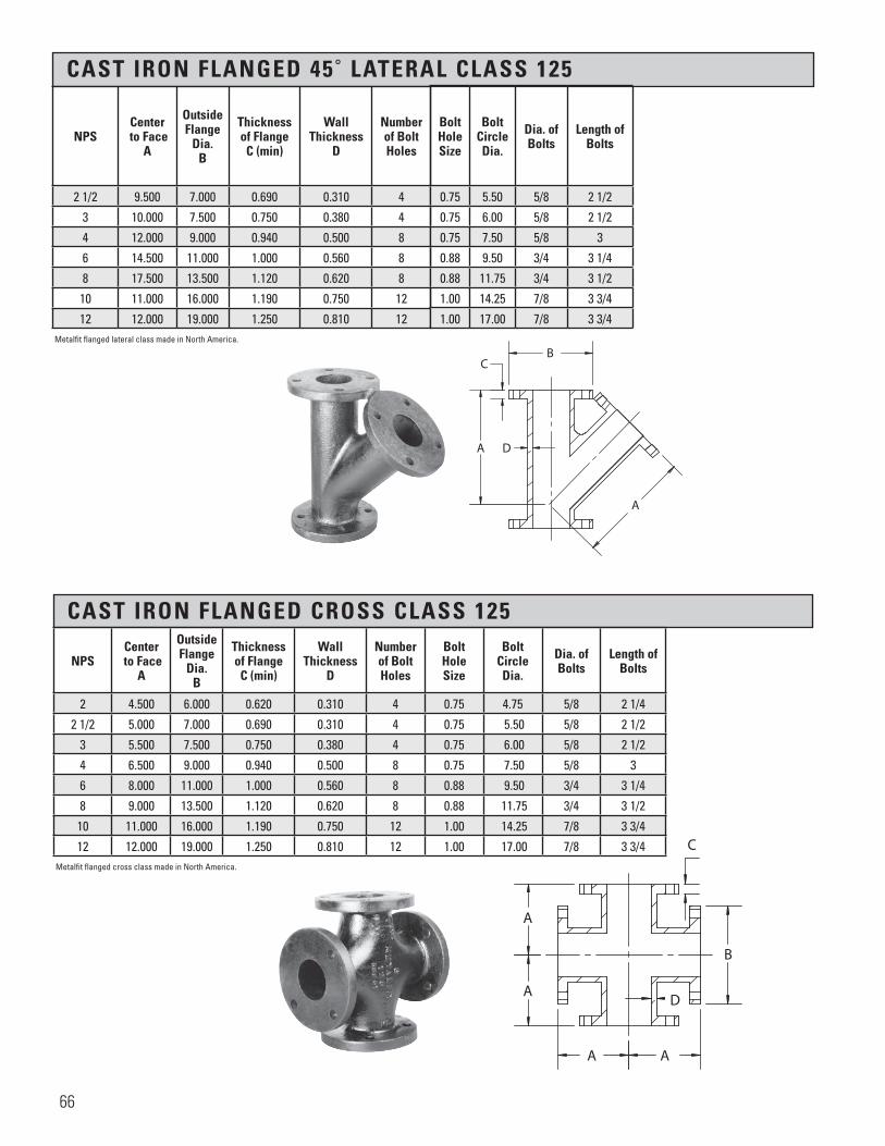
CAST IRON FLANGED 45˚ LATERAL CLASS 125
CAST IRON FLANGED CROSS CLASS 125
NPSCenter
to FaceA
Outside Flange
Dia.B
Thicknessof Flange
C (min)
WallThickness
D
Numberof Bolt Holes
2 1/2 9.500 7.000 0.690 0.310 4
3 10.000 7.500 0.750 0.380 4
4 12.000 9.000 0.940 0.500 8
6 14.500 11.000 1.000 0.560 8
8 17.500 13.500 1.120 0.620 8
10 11.000 16.000 1.190 0.750 12
12 12.000 19.000 1.250 0.810 12
BoltHoleSize
BoltCircleDia.
Dia. of Bolts
Length of Bolts
0.75 5.50 5/8 2 1/2
0.75 6.00 5/8 2 1/2
0.75 7.50 5/8 3
0.88 9.50 3/4 3 1/4
0.88 11.75 3/4 3 1/2
1.00 14.25 7/8 3 3/4
1.00 17.00 7/8 3 3/4
NPSCenter
to FaceA
Outside Flange
Dia.B
Thicknessof Flange
C (min)
WallThickness
D
Numberof Bolt Holes
BoltHoleSize
BoltCircleDia.
Dia. of Bolts
Length of Bolts
2 4.500 6.000 0.620 0.310 4 0.75 4.75 5/8 2 1/4
2 1/2 5.000 7.000 0.690 0.310 4 0.75 5.50 5/8 2 1/2
3 5.500 7.500 0.750 0.380 4 0.75 6.00 5/8 2 1/2
4 6.500 9.000 0.940 0.500 8 0.75 7.50 5/8 3
6 8.000 11.000 1.000 0.560 8 0.88 9.50 3/4 3 1/4
8 9.000 13.500 1.120 0.620 8 0.88 11.75 3/4 3 1/2
10 11.000 16.000 1.190 0.750 12 1.00 14.25 7/8 3 3/4
12 12.000 19.000 1.250 0.810 12 1.00 17.00 7/8 3 3/4
Metalfit flanged lateral class made in North America.
Metalfit flanged cross class made in North America.
����
����
����
����
�
A
C
B
D
A A
A
�����������������
A
A
CB
D
66
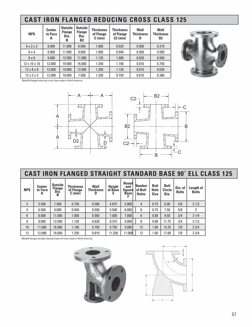
CAST IRON FLANGED REDUCING CROSS CLASS 125
NPSCenter
to FaceA
Outside Flange
Dia.B
OutsideFlange
Dia.B2
Thicknessof Flange
C (min)
Thicknessof FlangeC2 (min)
WallThickness
D
WallThickness
D2
6 x 2 x 2 8.000 11.000 6.000 1.000 0.620 0.560 0.310
6 x 4 8.000 11.000 9.000 1.000 0.940 0.560 0.500
8 x 6 9.000 13.500 11.000 1.120 1.000 0.620 0.560
12 x 10 x 10 12.000 19.000 16.000 1.250 1.190 0.810 0.750
12 x 8 x 8 12.000 19.000 13.500 1.250 1.120 0.810 0.620
12 x 3 x 3 12.000 19.000 7.500 1.250 0.750 0.810 0.380
CAST IRON FLANGED STRAIGHT STANDARD BASE 90˚ ELL CLASS 125
NPSCenter
to FaceA
Outside Flange
Dia.B
Thicknessof Flange
C (min)
WallThickness
D
Height of Base
E
Roundand
SquareBase
F
3 5.500 7.500 0.750 0.380 4.875 5.000
4 6.500 9.000 0.940 0.500 5.500 6.000
6 8.000 11.000 1.000 0.560 7.000 7.000
8 9.000 13.500 1.120 0.620 8.375 9.000
10 11.000 16.000 1.190 0.750 9.750 9.000
12 12.000 19.000 1.250 0.810 11.250 11.000
Numberof Bolt Holes
BoltHoleSize
BoltCircleDia.
Dia. ofBolts
Length ofBolts
4 0.75 6.00 5/8 2 1/2
8 0.75 7.50 5/8 3
8 0.88 9.50 3/4 3 1/4
8 0.88 11.75 3/4 3 1/2
12 1.00 14.25 7/8 3 3/4
12 1.00 17.00 7/8 3 3/4
H H
F
E
B
D
C
A
SECTION H-H SCALE 1 : 4
Section 7 Page 66Cast Iron Flanged Straight Standard Base Ell, Class 125
X.BFBL
All information contained within this document is intended for the sole use of Ward Manufacturingand may not be released, used, copied, or distributed without the express written permission of ...
WARD MANUFACTURING LLCBLOSSBURG, PA. 16912, USA
(570) 638-2131
TITLE:
MATERIAL:
DRAWN BY:
SHEET:
DATE: CHECKED BY: DATE:
SCALE: SIZE: SMARTEAM I.D.:
DATE DESCRIPTION APR
PART NO.:
REV.
XX-XXXXXXXXX
E.C.O. #
NEW SOLIDWORKS DRAWING01 XXX
ANGULARITY: ±1
SURFACE FINISH:63
±.031 FOR THE FIRST INCH,AND AN ADDITIONAL ±.005
FOR EACH ADDITIONAL INCH
DECIMAL PLACE:.X ±.03.XX ±.01.XXX ±.005
AS-CAST SURFACES MACHINED SURFACESUN THREADS - EXTERNAL: CLASS 2A, INTERNAL: CLASS 2B
TOLERANCES AND SPECIFICATIONSUNLESS OTHERWISE NOTED:
THIS IS A CAD DRAWING,DO NOT ADD HAND WRITTEN EDITS
XX/XX/XX
1 OF 1 B
ALL DIMENSIONS ARE IN INCHES UNLESS OTHERWISE NOTEDDRAWN IN ACCORDANCE WITH ASME Y14.5
BREAK ALL SHARP CORNERS AND REMOVE ALL BURRSDRAFT ANGLE IS 2° UNLESS NOTED OTHERWISE
THREADS:
REV.
Metalfit flanged reducing cross class made in North America.
Metalfit flanged straight standard base ell class made in North America.
�����������������
A A
B C
B
C
B2C2
B2
C2
A
ADD2
67

CAST IRON FLANGED STRAIGHT STANDARD BASE TEES CLASS 125
NPSCenter
to FaceA
Outside Flange
Dia.B
Thicknessof Flange
C (min)
WallThickness
D
Height of Base
E
Roundand
SquareBase
F
Numberof Bolt Holes
BoltHoleSize
BoltCircleDia.
Dia. of Bolt
Length of Bolts
3 5.500 7.500 0.750 0.380 4.875 5.000 4 3/4 6 5/8 2 1/2
4 6.500 9.000 0.940 0.500 5.500 6.000 8 3/4 7 1/2 5/8 3
5 7.500 10.000 0.940 0.500 7.000 7.000 8 7/8 8 1/2 3/4 3
6 8.000 11.000 1.000 0.560 7.000 7.000 8 7/8 9 1/2 3/4 3 1/4
8 9.000 13.500 1.120 0.620 8.375 9.000 8 7/8 11 3/4 3/4 3 1/2
10 11.000 16.000 1.190 0.750 9.750 9.000 12 1 14 1/4 7/8 3 3/4
12 12.000 19.000 1.250 0.810 11.250 11.000 12 1 17 7/8 3 3/4Metalfit flanged straight standard base tee class made in North America.
A A
A A
E
F
B
C
D
SECTION A-A SCALE 1 : 4
Section 7 Page 66Cast Iron Straight Base Tee, Class 125
X.BFBT
D
C
B
AA
B
C
D
12345678
8 7 6 5 4 3 2 1
THE INFORMATION CONTAINED IN THISDRAWING IS THE SOLE PROPERTY OF<INSERT COMPANY NAME HERE>. ANY REPRODUCTION IN PART OR AS A WHOLEWITHOUT THE WRITTEN PERMISSION OF<INSERT COMPANY NAME HERE> IS PROHIBITED.
PROPRIETARY AND CONFIDENTIAL
NEXT ASSY USED ON
APPLICATION
DIMENSIONS ARE IN INCHESTOLERANCES:FRACTIONALANGULAR: MACH BEND TWO PLACE DECIMAL THREE PLACE DECIMAL
INTERPRET GEOMETRICTOLERANCING PER:
MATERIAL
FINISH
DRAWN
CHECKED
ENG APPR.
MFG APPR.
Q.A.
COMMENTS:
DATENAME
TITLE:
SIZE
BDWG. NO. REV
WEIGHT: SCALE: 1:1
UNLESS OTHERWISE SPECIFIED:
SHEET 1 OF 1
X.BFBTDO NOT SCALE DRAWING
68

SECTION 8 CAST IRON DRAINAGE FITTINGS
Material: ASTM A 126 Class A Minimum
Dimensions: ASME B16.12 ANSI/ASME B.1.20.1
Pressure ASME B16.12 Rating:
Coatings: ASTM A153
Additional UL, ULC AND FM, where applicable Specifications:
NPSThreadLength (min)
TotalLength of
Chamber toShoulder
I.D. ofFittings
WallThickness
(min)
O.D. of Band (min)
1 1/4 0.42 0.71 1.38 0.18 2.39
1 1/2 0.42 0.72 1.61 0.20 2.68
2 0.44 0.76 2.07 0.22 3.28
2 1/2 0.68 1.14 2.47 0.24 3.86
3 0.77 1.20 3.07 0.26 4.62
4 0.84 1.30 4.03 0.31 5.79
WARD cast iron drainage fittings, shown on the following pages, are designed especially for drainage systems using wrought pipe. The in-side diameter of the fitting is the same as that of wrought pipe.
WARD drainage fittings are made with an interior shoulder, so that when the joint is made the end of the pipe practically meets the shoulder. This forms a continuous unobstructed surface providing smooth flow of the pipe contents.
WARD 90 degree ells, except for the street ells, are pitched 1/4 inchper foot. WARD drainage fit-tings meet existing requirements for the sanitary codes and are manufactured in strict accordance with an American National Standard.
IMPORTANTBe sure to specify the type of finish desired. As with the rest of the WARD line of fittings, drainage can be supplied in black or galvanized.
69

CAST IRON DRAINAGE 45˚ ELL SHORT TURN
NPSCenterto End
A
OutsideDia. of Band
B (min)
Length of ThreadsC (min)
Take Out
1 1/4 1.31 2.39 0.42 0.60
1 1/2 1.44 2.68 0.42 0.71
2 1.69 3.28 0.44 0.93
3 2.19 4.62 0.77 0.99
4 2.63 5.79 0.84 1.33
�����������������
AB
A
C
CAST IRON DRAINAGE 45˚ ELL LONG TURN
NPSCenterto End
A
OutsideDia. of Band
B (min)
Length of ThreadsC (min)
Take Out
1 1/2 — — — —
2 2.25 3.28 0.44 1.49
�����������������
AB
A
C
CAST IRON DRAINAGE 90˚ STRAIGHT ELL SHORT TURN
NPSCenterto End
A
OutsideDia. of Band
B (min)
Length of ThreadsC (min)
Take Out
1 1/4 1.75 2.39 0.42 1.04
1 1/2 1.94 2.68 0.42 1.21
2 2.25 3.28 0.44 1.49
3 3.06 4.62 0.77 1.86
4 3.81 5.79 0.84 2.51
1 1/2 x 1 1/4 — — — —
2 x 1 1/2 2.25 3.28 0.44 1.49/1.21
�����������������
A
A
C
B
70

CAST IRON DRAINAGE 90˚ STREET ELL
NPSCenterto End
A
Centerto Male
B
Outside Dia. of Band
C (min)
Port Dia.Male End
D (max)
Length of Internal ThreadsE (min)
Length of External ThreadsF (min)
Take Out
Male End
Take Out
Female End
1 1/2 1.98 2.86 2.68 1.35 0.42 0.85 2.13 1.25
2 — — — — — — — —
CAST IRON DRAINAGE 90˚ STRAIGHT ELL LONG TURN
NPSCenterto End
A
OutsideDia. of Band
B (min)
Length of ThreadsC (min)
Take Out
1 1/2 2.50 2.68 0.42 1.77
2 3.06 3.28 0.44 2.30
3 4.25 4.62 0.77 3.00
�����������������
A
C
A
B
CAST IRON DRAINAGE 90˚ STRAIGHT ELL EXTRA LONG TURN
NPSCenterto End
A
OutsideDia. of Band
B (min)
Length of ThreadsC (min)
Take Out
1 1/2 3.50 2.68 0.42 2.77
2 4.00 3.28 0.44 3.24
������������������
A
D
E
C
G
F
BB
B
C
A
A
SECTION B-B
Section 8 Page 69Cast Iron Drainage 90 Straight Ell Extra Long Turn, Class 125
X.BDXLTL
DO NOT SCALE DRAWING
X.BDXLTLSHEET 1 OF 1
UNLESS OTHERWISE SPECIFIED:
SCALE: 1:4 WEIGHT:
REVDWG. NO.
ASIZE
TITLE:
NAME DATE
COMMENTS:
Q.A.
MFG APPR.
ENG APPR.
CHECKED
DRAWN
FINISH
MATERIAL
INTERPRET GEOMETRICTOLERANCING PER:
DIMENSIONS ARE IN INCHESTOLERANCES:FRACTIONALANGULAR: MACH BEND TWO PLACE DECIMAL THREE PLACE DECIMAL
APPLICATION
USED ONNEXT ASSY
PROPRIETARY AND CONFIDENTIALTHE INFORMATION CONTAINED IN THISDRAWING IS THE SOLE PROPERTY OF<INSERT COMPANY NAME HERE>. ANY REPRODUCTION IN PART OR AS A WHOLEWITHOUT THE WRITTEN PERMISSION OF<INSERT COMPANY NAME HERE> IS PROHIBITED.
5 4 3 2 1
71

CAST IRON DRAINAGE 45˚ STREET ELL
CAST IRON DRAINAGE 60˚ STREET ELL SHORT TURN
CAST IRON DRAINAGE STRAIGHT TEE
NPSCenterto End
A
Outside Dia. of Band
B (min)
Length of ThreadsC (min)
Take Out
1 1/2 1.75 2.68 0.42 1.02
2 2.06 3.28 0.44 1.30
NPSCenterto End
A
Outside Dia. of Band
B (min)
Length of ThreadsC (min)
Take Out
1 1/2 1.94 2.68 0.42 1.21
2 2.25 3.28 0.44 1.49
2 X 1/2 2.25 3.28 0.44 1.49
NPSCenterto End
A
Centerto Male
B
Outside Dia. of Band
C (min)
Port Dia. Male End
D (max)
Length of Internal ThreadsE (min)
Length of External ThreadsF (min)
Take Out
Male End
Take Out
Female End
1 1/2 1.50 1.87 2.68 1.35 0.42 0.85 1.15 0.77
2 1.65 2.30 3.28 1.75 0.44 0.87 1.54 0.89
�
����
��������
������
A
A
B
C
A
������������������
A
A
B
C
������������������
CA
E
F
D
B
72

CAST IRON DRAINAGE 90˚ “TY” SHORT TURN
CAST IRON DRAINAGE 22 1/2˚ ELLS SHORT TURN
CAST IRON DRAINAGE 11 1/4˚ ELLS SHORT TURN
NPSCenterto End
A
Outside Dia. of Band
B (min)
Length of ThreadsC (min)
Take Out
1 1/2 1.25 2.68 0.42 0.52
2 1.44 3.28 0.44 0.68
NPS
Centerto End Inlet
A
Centerto End Outlet
B
Centerto End
C
End to End
D
OutsideDia. of Band.E (min)
OutsideDia of Band.
E2 (min)
OutsideDia. of Band
E3 (min)
Length of ThreadsF (min)
Length of ThreadsF2 (min)
Length of ThreadsF3 (min)
Take Out
Take Out
1 1/2 2.50 2.50 1.75 4.25 2.68 2.68 2.68 0.42 0.42 0.42 1.78 1.78
2 3.06 3.06 2.13 5.19 3.28 3.28 3.28 0.44 0.44 0.44 2.30 2.30
4 5.19 5.19 3.56 8.75 5.79 5.79 5.79 0.84 0.84 0.84 3.89 3.89
2 x 1 1/2 2.94 2.69 1.94 4.63 3.28 3.28 2.68 0.44 0.44 0.42 2.18 1.93
2 x 1 1/2 x 1 1/2 2.94 2.69 1.94 4.63 3.28 2.68 2.68 0.44 0.420 0.42 2.18 1.93
2 x 1 1/2 x 2 3.06 3.06 2.13 5.19 3.28 2.68 3.28 0.44 0.42 0.44 2.30 2.30
NPSCenterTo End
A
Outside Dia. of Band
B (min)
Length of ThreadsC (min)
Take Out
1 1/2 1.25 2.68 0.42 0.52
2 1.38 3.28 0.44 0.62
����
����
����
����
��
A
B
AC
�
����
����
����
����
��
B
A
AC
AA
E2
F2
C
D
B
E3F3
E
F
A
SECTION A-A
Section 8 Page 71C.I. Drainage 90 "TY" Short Turn, Class 125
X.BDTY
D
C
B
AA
B
C
D
12345678
8 7 6 5 4 3 2 1
THE INFORMATION CONTAINED IN THISDRAWING IS THE SOLE PROPERTY OF<INSERT COMPANY NAME HERE>. ANY REPRODUCTION IN PART OR AS A WHOLEWITHOUT THE WRITTEN PERMISSION OF<INSERT COMPANY NAME HERE> IS PROHIBITED.
PROPRIETARY AND CONFIDENTIAL
NEXT ASSY USED ON
APPLICATION
DIMENSIONS ARE IN INCHESTOLERANCES:FRACTIONALANGULAR: MACH BEND TWO PLACE DECIMAL THREE PLACE DECIMAL
INTERPRET GEOMETRICTOLERANCING PER:
MATERIAL
FINISH
DRAWN
CHECKED
ENG APPR.
MFG APPR.
Q.A.
COMMENTS:
DATENAME
TITLE:
SIZE
BDWG. NO. REV
WEIGHT: SCALE: 1:2
UNLESS OTHERWISE SPECIFIED:
SHEET 1 OF 1
X.BDTYDO NOT SCALE DRAWING
73

CAST IRON DRAINAGE 90˚ “TY” LONG TURN
CAST IRON DRAINAGE 45˚ “Y” SHORT TURN
NPS
Centerto End Inlet
A
Centerto End Outlet
B
Centerto End
C
End to End
D
OutsideDia. of Band
E (min)
OutsideDia. of Band
E2 (min)
OutsideDia. of Band
E3 (min)
Length of ThreadsF (min)
Length of ThreadsF2 (min)
Length of ThreadsF3 (min)
Take Out
Take Out
1 1/4 3.25 3.25 1.75 5.00 2.39 2.39 2.39 0.42 0.42 0.42 2.54 2.54
1 1/2 3.63 3.63 1.88 5.50 2.68 2.68 2.68 0.42 0.42 0.42 2.91 2.91
2 4.38 4.38 2.13 6.50 3.28 3.28 3.28 0.44 0.44 0.440 3.62 3.62
3 — — — — — — — — — — — —
4 7.69 7.69 3.19 10.88 5.79 5.79 5.79 0.84 0.84 0.84 6.39 6.39
2 x 1 1/2 4.13 4.06 1.81 5.88 3.28 3.28 2.68 0.44 0.44 0.42 3.37 3.30
2 x 1 1/2 x 1 1/2 4.13 4.06 1.81 5.88 3.28 2.68 2.68 0.44 0.42 0.42 3.37 3.30
2 x 1 1/2 x 2 4.38 4.38 2.13 6.50 3.28 2.68 3.28 0.44 0.42 0.440 3.62 3.62
4 x 3 7.19 6.88 2.38 9.25 5.79 5.79 4.62 0.84 0.84 0.77 5.89 5.58
4 x 2 6.31 6.00 1.69 7.69 5.79 5.79 3.28 0.84 0.84 0.44 5.01 4.70
NPS
Centerto End Inlet
A
Centerto End Outlet
B
Centerto End
C
End to End
D
OutsideDia. of Band
E (min))
OutsideDia. of Band
E2 (min)
OutsideDia. of Band
E3 (min)
Length of ThreadsF (min)
Length of ThreadsF1 (min)
Length of ThreadsF2 (min)
Take Out
Take Out
1 1/2 4.13 4.13 1.25 5.38 2.68 2.68 2.68 0.42 0.42 0.42 3.4 3.41
2 5.25 5.25 1.75 7.00 3.28 3.28 3.28 0.44 0.44 0.44 4.49 4.49
2 x 1 1/2 4.38 4.44 1.31 5.75 3.28 3.28 2.68 0.44 0.44 0.42 3.62 3.68
2 x 1 1/2 x 1 1/2 4.38 4.44 1.31 5.75 3.28 2.68 2.68 0.44 0.42 0.42 3.62 3.68
2 x 1 1/2 x 2 5.25 5.25 1.75 7.00 3.28 2.68 3.28 0.44 0.42 0.44 4.49 4.49
������������������
A
D
F
E
E2
E3
CB
F2
F3
H H
2 NPT Tapped Hole
E
F
B
E
F3
F2
E2
D
C
A
Section 8 Page 72Cast Iron 90 "TY" Long Turn, Class 125
X.BDLTTY
All information contained within this document is intended for the sole use of Ward Manufacturingand may not be released, used, copied, or distributed without the express written permission of ...
WARD MANUFACTURING LLCBLOSSBURG, PA. 16912, USA
(570) 638-2131
TITLE:
MATERIAL:
DRAWN BY:
SHEET:
DATE: CHECKED BY: DATE:
SCALE: SIZE: SMARTEAM I.D.:
DATE DESCRIPTION APR
PART NO.:
REV.
XX-XXXXXXXXX
E.C.O. #
NEW SOLIDWORKS DRAWING01 XXX
ANGULARITY: ±1
SURFACE FINISH:63
±.031 FOR THE FIRST INCH,AND AN ADDITIONAL ±.005
FOR EACH ADDITIONAL INCH
DECIMAL PLACE:.X ±.03.XX ±.01.XXX ±.005
AS-CAST SURFACES MACHINED SURFACESUN THREADS - EXTERNAL: CLASS 2A, INTERNAL: CLASS 2B
TOLERANCES AND SPECIFICATIONSUNLESS OTHERWISE NOTED:
THIS IS A CAD DRAWING,DO NOT ADD HAND WRITTEN EDITS
XX/XX/XX
90° DRAINAGE TY- LONG TURN
*.BDLTTYCast Iron
1 OF 1 B
ALL DIMENSIONS ARE IN INCHES UNLESS OTHERWISE NOTEDDRAWN IN ACCORDANCE WITH ASME Y14.5
BREAK ALL SHARP CORNERS AND REMOVE ALL BURRSDRAFT ANGLE IS 2° UNLESS NOTED OTHERWISE
THREADS:
REV.
74
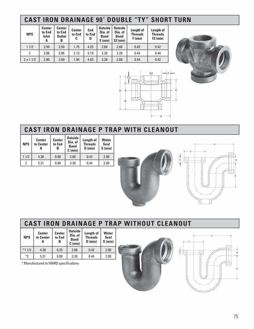
CAST IRON DRAINAGE P TRAP WITH CLEANOUT
CAST IRON DRAINAGE P TRAP WITHOUT CLEANOUT
CAST IRON DRAINAGE 90˚ DOUBLE “TY” SHORT TURN
NPSCenter
to CenterA
Centerto End
B
OutsideDia. of Band
C (min)
Length ofThreadsD (min)
WaterSeal
S (min)
1 1/2 4.38 0.88 2.68 0.42 2.00
2 5.31 0.88 3.28 0.44 2.00
NPSCenter
to CenterA
Centerto End
B
OutsideDia. of Band
C (min)
Length ofThreadsD (min)
WaterSeal
S (min)
*1 1/2 4.38 0.25 2.68 0.42 2.00
*2 5.31 0.00 3.28 0.44 2.00
NPS
Centerto End Inlet
A
Centerto End Outlet
B
Centerto End
C
End to End
D
OutsideDia. of Band
E (min)
OutsideDia. of Band
E2 (min)
Length of ThreadsF (min)
Length of ThreadsF2 (min)
1 1/2 2.50 2.50 1.75 4.25 2.68 2.68 0.42 0.42
2 3.06 3.06 2.13 5.19 3.28 3.28 0.44 0.44
2 x 1 1/2 2.90 2.69 1.94 4.63 3.28 2.68 0.44 0.42
* Manufactured to WARD specifications
����
����
����
����
��
A
C
S
BD
����
����
����
����
��
A
B
S
C
D
����
����
����
����
��
F2
C
E2 F
E
B
D
A
75

SECTION 9 WARDLOX ™
Introduced in 1983, the WARDLOX sprinkler connect system is a fast, safe and effective way to join schedule 10 and 40 plain end pipe without threading or welding.
In addition to the performance benefits of threadless sprinkler connect systems, the WARDLOX system is 100% factory tested to prevent leaks and recalls.WARDLOX has also been thoroughly field tested in a variety of installations and is ideal for new construction and retrofit. Designed to reduce the number of hands required to install a total fire protection system, WARDLOX features:• Self-locking screws for quick and easy installation. • Uniform 1⁄2 inch “take out” dimensions for accurate onsite.measurement and set screw placement engineered for-ward of the gasket to eliminate risk of leakageWARDLOX fittings and set screws are engineered to provide a more positive locking action when the set screw is tightened down to the boss on the fitting.Providing maximum contact in the pipe, the bottom of the set screw is convex and tapered. The 3/8 inch square head set screw can be tightened with the same tool used for affixing beam clamps.The exclusive nylon “lock patch” on the cadmium plated set screw prevents screw loosening caused by vibration after fabrication and installation. Your sprinkler system components can be fabricated in the shop; the fittings will not shake loose during transport. Set screws are pre-set at the factory so that field assembly requires only one turn to tighten the head securely against the casting. Installation in confined areas is fast and easy.Material Specifications Housing: Cast Iron to ASTM A126 Class A minimum. Galvanized finish also available forspecial applications or high corrosion areas. Set Screws: Carbon Steel, Cadmium Plated, Self-Locking Gaskets: E.P.D.M. to ASTM D-2000 With Temperature Range of -30 to 230 Threaded Outlets: Conform to ANSI B1.20.1 Specifications Pressure Ratings: 175 psig
Material: ASTM A126 Class A Minimum
Dimensions: ANSI/ASME B1.20.1
Coatings: ASTM A153 ASTM B633
Pressure Ratings: 175 psig
Additional UL, ULC and FM where applicable Specifications:
76

WARDLOX SLIP TEES (SLIP X SLIP X SLIP)
NPSCenter to End
A
Pipe Engagement
C
Take Out
Schedule Pipe Approved
1 x 1 x 1 2.56 1.62 0.93 40, 10, XL, DT, DF
1 1/4 x 1 1/4 x 1 1/4 2.75 1.62 1.13 40, 10, XL, DT, DF
1 1/2 x 1 1/2 x 1 1/2 2.87 1.62 1.25 40, 10
2 x 2 x 2 3.22 1.75 1.56 40, 10
WARDLOX 90˚ ELBOW (SLIP X SLIP)
NPSCenter to End
A
Pipe Engagement
Take Out
Schedule Pipe Approved
1 2.37 1.62 0.75 40, 10, XL, DT, D
1 1/4 2.56 1.62 0.94 40, 10, XL, DT, D
1 1/2 2.68 1.62 0.69 40, 10
2 3.06 1.75 0.94 40, 10
WARDLOX ADAPTER ELBOW (SLIP X THREAD)
NPSCenter to End
A1
Center to End
A2
Pipe Engagement
Take Out
Schedule Pipe Approved
1 x 1 1.56 2.56 1.62 0.93 40, 10, XL, DT, DF
1 x 3/4 1.56 2.44 1.62 0.81 40, 10, XL, DT, DF
1 x 1/2 1.56 2.44 1.62 0.81 40, 10, XL, DT, DF
1 1/4 x 1 1.81 2.56 1.62 0.81 40, 10, XL, DT, DF
1 1/4 x 3/4 1.81 2.56 162 0.81 40, 10, XL, DT, DF
1 1/4 x 1/2 1.81 2.56 1.62 0.81 40, 10, XL, DT, DF
1 1/2 x 1 1.93 2.56 1.62 0.81 40, 10
1 1/2 x 3/4 1.93 2.56 1.62 0.81 40, 10
1 1/2 x 1/2 1.93 2.56 1.62 0.81 40, 10
2 x 1 2.62 2.69 2.75 0.81 40, 10
2 x 3/4 2.62 2.69 2.75 0.81 40, 10
2 x 1/2 2.62 2.69 2.75 0.81 40, 10
A
COUTTAKE
A
C
OUTTAKE
Page 78Wardlox 90 Straight Ell (Slip x Slip)
X.BWL
D
C
B
AA
B
C
D
12345678
8 7 6 5 4 3 2 1
THE INFORMATION CONTAINED IN THISDRAWING IS THE SOLE PROPERTY OF<INSERT COMPANY NAME HERE>. ANY REPRODUCTION IN PART OR AS A WHOLEWITHOUT THE WRITTEN PERMISSION OF<INSERT COMPANY NAME HERE> IS PROHIBITED.
PROPRIETARY AND CONFIDENTIAL
NEXT ASSY USED ON
APPLICATION
DIMENSIONS ARE IN INCHESTOLERANCES:FRACTIONALANGULAR: MACH BEND TWO PLACE DECIMAL THREE PLACE DECIMAL
INTERPRET GEOMETRICTOLERANCING PER:
MATERIAL
FINISH
DRAWN
CHECKED
ENG APPR.
MFG APPR.
Q.A.
COMMENTS:
DATENAME
TITLE:
SIZE
BDWG. NO. REV
WEIGHT: SCALE: 1:2
UNLESS OTHERWISE SPECIFIED:
SHEET 1 OF 1
1.BWLDO NOT SCALE DRAWING
A2
OUTTAKEC
A1
Section 10 Page 79Wardlox Adapter Ell (Slip x NPT Thread)
X.BWL
D
C
B
AA
B
C
D
12345678
8 7 6 5 4 3 2 1
THE INFORMATION CONTAINED IN THISDRAWING IS THE SOLE PROPERTY OF<INSERT COMPANY NAME HERE>. ANY REPRODUCTION IN PART OR AS A WHOLEWITHOUT THE WRITTEN PERMISSION OF<INSERT COMPANY NAME HERE> IS PROHIBITED.
PROPRIETARY AND CONFIDENTIAL
NEXT ASSY USED ON
APPLICATION
DIMENSIONS ARE IN INCHESTOLERANCES:FRACTIONALANGULAR: MACH BEND TWO PLACE DECIMAL THREE PLACE DECIMAL
INTERPRET GEOMETRICTOLERANCING PER:
MATERIAL
FINISH
DRAWN
CHECKED
ENG APPR.
MFG APPR.
Q.A.
COMMENTS:
DATENAME
TITLE:
SIZE
BDWG. NO. REV
WEIGHT: SCALE: 1:1
UNLESS OTHERWISE SPECIFIED:
SHEET 1 OF 1
1XD.BWLDO NOT SCALE DRAWING
TAKEOUT C
A
WARDLOX SLIP TEEPAGE 75
All information contained within this document is intended for the sole use of Ward Manufacturingand may not be released, used, copied, or distributed without the express written permission of ...
WARD MANUFACTURING LLCBLOSSBURG, PA. 16912, USA
(570) 638-2131
TITLE:
MATERIAL:
DRAWN BY:
SHEET:
DATE: CHECKED BY: DATE:
SCALE: SIZE: SMARTEAM I.D.:
DATE DESCRIPTION APR
PART NO.:
REV.
XX-XXXXXXXXX
E.C.O. #
NEW SOLIDWORKS DRAWING01 XXX
ANGULARITY: ±1
SURFACE FINISH:63
±.031 FOR THE FIRST INCH,AND AN ADDITIONAL ±.005
FOR EACH ADDITIONAL INCH
DECIMAL PLACE:.X ±.03.XX ±.01.XXX ±.005
AS-CAST SURFACES MACHINED SURFACESUN THREADS - EXTERNAL: CLASS 2A, INTERNAL: CLASS 2B
TOLERANCES AND SPECIFICATIONSUNLESS OTHERWISE NOTED:
THIS IS A CAD DRAWING,DO NOT ADD HAND WRITTEN EDITS
XX/XX/XX
1 OF 1 B
ALL DIMENSIONS ARE IN INCHES UNLESS OTHERWISE NOTEDDRAWN IN ACCORDANCE WITH ASME Y14.5
BREAK ALL SHARP CORNERS AND REMOVE ALL BURRSDRAFT ANGLE IS 2° UNLESS NOTED OTHERWISE
THREADS:
REV.
77

WARDLOX REDUCING SLIP TEES (SLIP X SLIP X SLIP)
NPSPipe
EngagementA
Pipe Engagement
A2
Center to Outlet
B
Overall Length
C
Take Out
Take Out 2
Schedule Pipe
Approved
2 x 2 x 1 1.79 1.64 3.09 5.38 1.30 1.45 40, 10
2 x 2 x 1 1/4 1.79 1.63 3.13 5.38 1.34 1.50 40, 10
2 x 2 1 1/2 1.79 1.63 3.13 5.97 1.34 1.50 40, 10
WARDLOX BULLHEAD TEES (SLIP X SLIP X SLIP)
WARDLOX OUTLET TEES (SLIP X SLIP X THREAD)
NPSCenter to End
A
Pipe Engagement
Take Out
Schedule Pipe Approved
1 x 1 x 1 1.56 1.62 0.50 40, 10, XL, DT, D
1 x 1 x 3/4 1.56 1.62 0.50 40, 10, XL, DT, D
1 x 1 x 1/2 1.56 1.62 0.50 40, 10, XL, DT, D
1 1/4 x 1 1/4 x 1 1.84 1.62 0.50 40, 10, XL, DT, D
1 1/4 x 1 1/4 x 3/4 1.84 1.62 0.50 40, 10, XL, DT, D
1 1/4 x 1 1/4 x 1/2 1.84 1.62 0.50 40, 10, XL, DT, D
1 1/2 x 1 1/2 x 1 1.96 1.62 0.50 40, 10
1 1/2 x 1 1/2 x 3/4 1.96 1.62 0.50 40, 10
1 1/2 x 1 1/2 x 1/2 1.96 1.62 0.50 40, 10
2 x 2 x 1 2.06 1.75 0.50 40, 10
2 x 2 x 3/4 2.06 1.75 0.50 40, 10
2 x 2 x 1/2 2.06 1.75 0.50 40, 10
A2
TAKEOUT 1 C1
A
C2
TAKEOUT 2
WARDLOX BULLHEAD TEESPAGE 76
All information contained within this document is intended for the sole use of Ward Manufacturingand may not be released, used, copied, or distributed without the express written permission of ...
WARD MANUFACTURING LLCBLOSSBURG, PA. 16912, USA
(570) 638-2131
TITLE:
MATERIAL:
DRAWN BY:
SHEET:
DATE: CHECKED BY: DATE:
SCALE: SIZE: SMARTEAM I.D.:
DATE DESCRIPTION APR
PART NO.:
REV.
XX-XXXXXXXXX
E.C.O. #
NEW SOLIDWORKS DRAWING01 XXX
ANGULARITY: ±1
SURFACE FINISH:63
±.031 FOR THE FIRST INCH,AND AN ADDITIONAL ±.005
FOR EACH ADDITIONAL INCH
DECIMAL PLACE:.X ±.03.XX ±.01.XXX ±.005
AS-CAST SURFACES MACHINED SURFACESUN THREADS - EXTERNAL: CLASS 2A, INTERNAL: CLASS 2B
TOLERANCES AND SPECIFICATIONSUNLESS OTHERWISE NOTED:
THIS IS A CAD DRAWING,DO NOT ADD HAND WRITTEN EDITS
XX/XX/XX
1 OF 1 B
ALL DIMENSIONS ARE IN INCHES UNLESS OTHERWISE NOTEDDRAWN IN ACCORDANCE WITH ASME Y14.5
BREAK ALL SHARP CORNERS AND REMOVE ALL BURRSDRAFT ANGLE IS 2° UNLESS NOTED OTHERWISE
THREADS:
REV.A
TAKEOUT C
Section 10 Page 76Wardlox Outlet Tees (Slip x Slip x NPT Thread)
X.BWT
All information contained within this document is intended for the sole use of Ward Manufacturingand may not be released, used, copied, or distributed without the express written permission of ...
WARD MANUFACTURING LLCBLOSSBURG, PA. 16912, USA
(570) 638-2131
TITLE:
MATERIAL:
DRAWN BY:
SHEET:
DATE: CHECKED BY: DATE:
SCALE: SIZE: SMARTEAM I.D.:
DATE DESCRIPTION APR
PART NO.:
REV.
XX-XXXXXXXXX
E.C.O. #
NEW SOLIDWORKS DRAWING01 XXX
ANGULARITY: ±1
SURFACE FINISH:63
±.031 FOR THE FIRST INCH,AND AN ADDITIONAL ±.005
FOR EACH ADDITIONAL INCH
DECIMAL PLACE:.X ±.03.XX ±.01.XXX ±.005
AS-CAST SURFACES MACHINED SURFACESUN THREADS - EXTERNAL: CLASS 2A, INTERNAL: CLASS 2B
TOLERANCES AND SPECIFICATIONSUNLESS OTHERWISE NOTED:
THIS IS A CAD DRAWING,DO NOT ADD HAND WRITTEN EDITS
XX/XX/XX
1 OF 1 B
ALL DIMENSIONS ARE IN INCHES UNLESS OTHERWISE NOTEDDRAWN IN ACCORDANCE WITH ASME Y14.5
BREAK ALL SHARP CORNERS AND REMOVE ALL BURRSDRAFT ANGLE IS 2° UNLESS NOTED OTHERWISE
THREADS:
REV.
C
TAKEOUT A
B
WARDLOX SLIP TEEPAGE 75
All information contained within this document is intended for the sole use of Ward Manufacturingand may not be released, used, copied, or distributed without the express written permission of ...
WARD MANUFACTURING LLCBLOSSBURG, PA. 16912, USA
(570) 638-2131
TITLE:
MATERIAL:
DRAWN BY:
SHEET:
DATE: CHECKED BY: DATE:
SCALE: SIZE: SMARTEAM I.D.:
DATE DESCRIPTION APR
PART NO.:
REV.
XX-XXXXXXXXX
E.C.O. #
NEW SOLIDWORKS DRAWING01 XXX
ANGULARITY: ±1
SURFACE FINISH:63
±.031 FOR THE FIRST INCH,AND AN ADDITIONAL ±.005
FOR EACH ADDITIONAL INCH
DECIMAL PLACE:.X ±.03.XX ±.01.XXX ±.005
AS-CAST SURFACES MACHINED SURFACESUN THREADS - EXTERNAL: CLASS 2A, INTERNAL: CLASS 2B
TOLERANCES AND SPECIFICATIONSUNLESS OTHERWISE NOTED:
THIS IS A CAD DRAWING,DO NOT ADD HAND WRITTEN EDITS
XX/XX/XX
1 OF 1 B
ALL DIMENSIONS ARE IN INCHES UNLESS OTHERWISE NOTEDDRAWN IN ACCORDANCE WITH ASME Y14.5
BREAK ALL SHARP CORNERS AND REMOVE ALL BURRSDRAFT ANGLE IS 2° UNLESS NOTED OTHERWISE
THREADS:
REV.
78
NPSCenter to End
A
Pipe Engagement
C1
Center to Outlet
C2
Take Out 1
Take Out 2
Schedule Pipe Approved
1 1/2 x 1 1/2 x 2 3.00 1.62 1.75 1.43 1.12 40, 10

WARDLOX COUPLINGS (SLIP X SLIP)
NPS LengthA
Pipe Engagement
C
Take Out
Schedule Pipe Approved
1 x 1 4.25 1.62 0.50 40, 10, XL, DT, D
1 1/4 x 1 1/4 4.25 1.62 0.50 40, 10, XL, DT, D
1 1/2 x 1 1/2 4.25 1.62 0.50 40, 10
2 x 2 4.25 1.75 0.50 40, 10
WARDLOX REDUCING OUTLET TEES (SLIP X SLIP X THREAD)
NPSCenter to End
A
Pipe Engagement
C1
Pipe Engagement
C2
Take Out
Schedule Pipe Approved
1 1/4 x 1 x 1 1.84 1.62 1.62 0.50 40, 10, XL, DT, D
1 1/4 x 1 x 3/4 1.84 1.62 1.62 0.50 40, 10, XL, DT, D
1 1/4 x 1 x 1/2 1.84 1.62 1.62 0.50 40, 10, XL, DT, D
1 1/2 x 1 1/4 x 1 1.96 1.62 1.62 0.50 40, 10
1 1/2 x 1 1/4 x 3/4 1.96 1.62 1.62 0.50 40, 10
1 1/2 x 1 1/4 x1/2 1.96 1.62 1.62 0.50 40, 10
2 x 1 1/2 x 1 2.16 1.75 1.62 0.50 40, 10
2 x 1 1/2 x 3/4 2.16 1.75 1.75 0.50 40, 10
2 X 1 1/2 x 1/2 2.16 1.75 1.62 0.50 40, 10
2 x 2 x 1 2.16 1.75 1.75 0.50 40, 10
2 x 2 x 3/4 2.16 1.75 1.75 0.50 40, 10
2 x 2 x 1/2 2.16 1.75 1.62 0.50 40, 10
A
CTAKEOUT
Page 77Wardlox Coupling (Slip x Slip)
X.BWC
D
C
B
AA
B
C
D
12345678
8 7 6 5 4 3 2 1
THE INFORMATION CONTAINED IN THISDRAWING IS THE SOLE PROPERTY OF<INSERT COMPANY NAME HERE>. ANY REPRODUCTION IN PART OR AS A WHOLEWITHOUT THE WRITTEN PERMISSION OF<INSERT COMPANY NAME HERE> IS PROHIBITED.
PROPRIETARY AND CONFIDENTIAL
NEXT ASSY USED ON
APPLICATION
DIMENSIONS ARE IN INCHESTOLERANCES:FRACTIONALANGULAR: MACH BEND TWO PLACE DECIMAL THREE PLACE DECIMAL
INTERPRET GEOMETRICTOLERANCING PER:
MATERIAL
FINISH
DRAWN
CHECKED
ENG APPR.
MFG APPR.
Q.A.
COMMENTS:
DATENAME
TITLE:
SIZE
BDWG. NO. REV
WEIGHT: SCALE: 1:1
UNLESS OTHERWISE SPECIFIED:
SHEET 1 OF 1
1.bwcDO NOT SCALE DRAWING
C1 C2
TAKEOUT
A
Page 77Wardlox Reducing Outlet Tee
X.BWT
D
C
B
AA
B
C
D
12345678
8 7 6 5 4 3 2 1
THE INFORMATION CONTAINED IN THISDRAWING IS THE SOLE PROPERTY OF<INSERT COMPANY NAME HERE>. ANY REPRODUCTION IN PART OR AS A WHOLEWITHOUT THE WRITTEN PERMISSION OF<INSERT COMPANY NAME HERE> IS PROHIBITED.
PROPRIETARY AND CONFIDENTIAL
NEXT ASSY USED ON
APPLICATION
DIMENSIONS ARE IN INCHESTOLERANCES:FRACTIONALANGULAR: MACH BEND TWO PLACE DECIMAL THREE PLACE DECIMAL
INTERPRET GEOMETRICTOLERANCING PER:
MATERIAL
FINISH
DRAWN
CHECKED
ENG APPR.
MFG APPR.
Q.A.
COMMENTS:
DATENAME
TITLE:
SIZE
BDWG. NO. REV
WEIGHT: SCALE: 1:2
UNLESS OTHERWISE SPECIFIED:
SHEET 1 OF 1
2X1DXD.BWTDO NOT SCALE DRAWING
79

SECTION 10 TEELOX ™ MECHANICAL BRANCH CONNECTOR
Designed for fast installation of bolted branch outlets, Teelox™ mechanical branch connectors are practical alternatives to existing branch connectsystems. Made from high quality cast iron, Teelox™ are known for long-lasting, maintenance-free performance.Key Features:• A high grade EPDM rubber gasket surrounds the locating collar for accurate, permanent installation and the best seal in the industry.• The locating collar is an integral part of the casting. • A zinc-plated high-tensile steel U-bolt ensures rust-free attachment. • Teelox™ is approved for conventional and arm-over installations.
Material: Cast Iron ASTM A126 Class A Minimum
Gasket: E.P.D.M. Rubber ASTM D-2000
U Bolt: Zinc Plated High-Tensile Steel
Dimensions: ANSI/ASME B1.20.1
Pressure Ratings: 175 psi
Coatings: ASTM B633, ASTM A153
Additional UL, ULC and FM where applicable Specifications:
Torque 20 ft.-lbs. max. Requirement:
NPSPipe Center
to OutletA
Hole Dia.B
Take Out
1 1/4 x 1/2 1.98 1.19 1.19
1 1/4 x 3/4 2.05 1.19 1.19
1 1/4 x 1 2.13 1.19 1.19
1 1/2 x 1/2 1.98 1.19 1.19
1 1/2 x 3/4 2.05 1.19 1.19
1 1/2 x 1 2.13 1.19 1.19
2 x 1/2 2.26 1.19 1.47
2 x 3/4 2.33 1.19 1.47
2 x 1 2.41 1.19 1.47
2 1/2 x 1/2 2.57 1.19 1.78
2 1/2 x 3/4 2.64 1.19 1.78
2 1/2 x 1 2.72 1.19 1.78
J J
C
A
OUTTAKE
Section 11 Page 81Teelox Mechanical Branch Connector
X.BTLX
All information contained within this document is intended for the sole use of Ward Manufacturingand may not be released, used, copied, or distributed without the express written permission of ...
WARD MANUFACTURING LLCBLOSSBURG, PA. 16912, USA
(570) 638-2131
TITLE:
MATERIAL:
DRAWN BY:
SHEET:
DATE: CHECKED BY: DATE:
SCALE: SIZE: SMARTEAM I.D.:
DATE DESCRIPTION APR
PART NO.:
REV.
XX-XXXXXXXXX
E.C.O. #
NEW SOLIDWORKS DRAWING01 XXX
ANGULARITY: ±1
SURFACE FINISH:63
±.031 FOR THE FIRST INCH,AND AN ADDITIONAL ±.005
FOR EACH ADDITIONAL INCH
DECIMAL PLACE:.X ±.03.XX ±.01.XXX ±.005
AS-CAST SURFACES MACHINED SURFACESUN THREADS - EXTERNAL: CLASS 2A, INTERNAL: CLASS 2B
TOLERANCES AND SPECIFICATIONSUNLESS OTHERWISE NOTED:
THIS IS A CAD DRAWING,DO NOT ADD HAND WRITTEN EDITS
XX/XX/XX
1 OF 1 B
ALL DIMENSIONS ARE IN INCHES UNLESS OTHERWISE NOTEDDRAWN IN ACCORDANCE WITH ASME Y14.5
BREAK ALL SHARP CORNERS AND REMOVE ALL BURRSDRAFT ANGLE IS 2° UNLESS NOTED OTHERWISE
THREADS:
REV.
80

SECTION 11 STANDARD MERCHANT COUPLINGS
FULL STEEL HALF STEEL
For general purpose, low-pressure piping, such as water, air, gas and oil lines. Material and dimensions conform to the requirements of ASTM A865.
Couplings in sizes ½ -2 NPS are supplied straight tapped. Couplings 2 NPS and larger are taper tapped.
NPSLength of Coupling
A
Outside Dia.
B (min)
1/2 1 9/16 1.063
3/4 1 5/8 1.313
1 2 1.576
1 1/4 2 1/16 1.900
1 1/2 2 1/16 2.200
2 2 1/8 2.750
2 1/2 3 1/8 3.250
3 3 1/4 4.000
4 3 1/2 5.000
5 3 3/4 6.296
6 4 7.390
NPSLength of Coupling
A
Outside Dia.
B (min)
1/2 0.750 1.063
3/4 0.781 1.313
1 0.969 1.576
1 1/4 1.000 1.900
1 1/2 1.000 2.200
2 1.063 2.750
2 1/2 1.563 3.250
3 1.594 4.000
4 1.719 5.000
5 1.844 6.396
6 1.969 7.390
B
A
STEE
L ST
RA
IGH
T C
OU
PLIN
G
All i
nfor
mat
ion
cont
aine
d w
ithin
this
doc
umen
t is i
nten
ded
for t
he so
le u
se o
f War
d M
anuf
actu
ring
and
may
not
be
rele
ased
, use
d, c
opie
d, o
r dis
trib
uted
with
out t
he e
xpre
ss w
ritte
n pe
rmis
sion
of .
..
WA
RD M
AN
UFA
CTU
RIN
G L
LCBL
OSS
BURG
, PA.
169
12, U
SA(5
70) 6
38-2
131
TITL
E:
MA
TERI
AL:
DRA
WN
BY:
SHEE
T:
DA
TE:
CH
ECKE
D B
Y:D
ATE
:
SCA
LE:
SIZE
:SM
ART
EAM
I.D
.:
DA
TED
ESCR
IPTI
ON
APR
PART
NO
.:
REV.
E.C.
O. #
ANG
ULA
RITY
: ±1
SURF
ACE
FIN
ISH
:63
±.03
1 FO
R TH
E FI
RST
INCH
,AN
D A
N A
DD
ITIO
NAL
±.0
05
FOR
EACH
AD
DIT
ION
AL IN
CH
DEC
IMAL
PLA
CE:
.X
±.0
3.X
X ±
.01
.XXX
±.0
05
AS-
CAST
SU
RFA
CES
MAC
HIN
ED S
URF
ACES
UN
TH
REA
DS
- EXT
ERN
AL:
CLA
SS 2
A, I
NTE
RNA
L: C
LASS
2B
TOLE
RAN
CES
AND
SPE
CIFI
CATI
ON
SU
NLE
SS O
THER
WIS
E N
OTE
D:
THIS
IS A
CA
D D
RAW
ING
,D
O N
OT
AD
D H
AN
D W
RITT
EN E
DIT
S
STA
ND
ARD
STE
EL C
OU
PLIN
GS
S.T.
(CH
ART
ED)
410X
XXX
DRE
11/1
2/20
09D
RE02
/08/
2012
1O
F1
1:1
07.D
B
ALL
DIM
ENSI
ON
S AR
E IN
INCH
ES U
NLE
SS O
THER
WIS
E N
OTE
DD
RAW
N IN
ACC
ORD
AN
CE W
ITH
ASM
E Y1
4.5
BREA
K A
LL S
HA
RP C
ORN
ERS
AN
D R
EMO
VE A
LL B
URR
SD
RAFT
AN
GLE
IS 2
° UN
LESS
NO
TED
OTH
ERW
ISE
THRE
ADS:
REV
.SW
D-0
0001
396
81

117 Gulick Street | Blossburg, PA 16912Phone: 800.248.1027 Fax: 570.241.0100
©2014 Ward Manufacturing, LLC, All rights reserved
www.wardmfg.com | www.ward�ttings.com
Top Related