


Languages
Pages
Legal

1 Quick Guide
1.1 Safety1.1.1 Warnings
High Voltage Warning:The voltage of the frequency converter is dangerous whenever it is connected to mains. Incorrect in-stallation of the motor or frequency converter may cause damage to the equipment, serious injury ordeath. Consequently, it is essential to comply with the instructions in this manual as well as local andnational rules and safety regulations.Warning:Touching the electrical parts may be fatal - even after the equipment has been disconnected from mains.Also make sure that other voltage inputs have been disconnected (linkage of DC intermediate circuit).Be aware that there may be high voltage on the DC link even when the LEDs are turned off.Before touching any potentially live parts of the frequency converter, wait at least 4 minutes for all M1,M2 and M3 sizes.Wait at least 15 minutes for all M4 and M5 sizes.Leakage Current:The earth leakage current from the frequency converter exceeds 3.5 mA. According to IEC 61800-5-1 areinforced Protective Earth connection must be ensured by means of a min. 10mm² Cu or an addtionalPE wire - with the same cable cross section as the Mains wiring - must be terminated separately.Residual Current Device:This product can cause a DC current in the protective conductor. Where a residual current device (RCD)is used for extra protection, only an RCD of Type B (time delayed) shall be used on the supply side ofthis product. See also Danfoss Application Note on RCD, MN.90.GX.YY.Protective earthing of the frequency converter and the use of RCDs must always follow national andlocal regulations.Motor Thermal Protection:Motor overload protection is possible by setting Parameter 1-90 Motor thermal protection to the valueETR trip. For the North American market: Implemented ETR function provide class 20 motor overloadprotection, in accordance with NEC.
Installation in high altitudes:For altitudes above 2 km, please contact Danfoss regarding PELV.
1.1.2 Safety Instructions
• Make sure the frequency converter is properly connected to earth.
• Do not remove mains connections, motor connections or other power connections while the frequency con-verter is connected to power.
• Protect users against supply voltage.
• Protect the motor against overloading according to national and local regulations.
• The earth leakage current exceeds 3.5 mA.
• The [OFF] key is not a safety switch. It does not disconnect the frequency converter from mains.
Quick Guide for VLT Micro FC 51 1 Quick Guide
MG.02.B5.02 - VLT® is a registered Danfoss trademark 1
1
1.2 Introduction1.2.1 Available Literature
This quick guide contains the basic information necessary for installing and running the drive.
If more information is needed, the literature below can be downloaded from:http: //www.danfoss.com/BusinessAreas/DrivesSolutions/Documentations
Title Literature no.VLT Micro Drive FC 51 Operating Instructions MG.02.AX.YYVLT Micro Drive FC 51 Quick Guide MG.02.BX.YYVLT Micro Drive FC 51 Programming Guide MG.02.CX.YYFC 51 LCP Mounting Instruction MI.02.AX.YYFC 51 De-coupling Plate Mounting Instruction MI.02.BX.YYFC 51 Remote Mounting Kit Mounting Instruction MI.02.CX.YYFC 51 DIN Rail Kit Mounting Instruction MI.02.DX.YYFC 51 IP21 Kit Mounting Instruction MI.02.EX.YYFC 51 Nema1 Kit Mounting Instruction MI.02.FX.YY
X = Revision Number, Y = Language code
1.2.2 Approvals
1.2.3 IT Mains
IT MainsInstallation on isolated mains source, i.e. IT mains.Max. supply voltage allowed when connected to mains: 440 V.
As an option, Danfoss offers recommended line filters for improved harmonics performance.
1.2.4 Avoid unintended Start
While the frequency converter is connected to mains, the motor can be started/stopped using digital commands, buscommands, references or via the Local Control Panel.
• Disconnect the frequency converter from mains whenever personal safety considerations make it necessaryto avoid unintended start of any motors.
• To avoid unintended start, always activate the [OFF] key before changing parameters.
1 Quick Guide Quick Guide for VLT Micro FC 51
2 MG.02.B5.02 - VLT® is a registered Danfoss trademark
1
1.2.5 Disposal Instruction
Equipment containing electrical components must not be disposed of together with do-mestic waste.It must be separately collected with electrical and electronic waste according to local andcurrently valid legislation.
1.3 Installation1.3.1 Before Commencing Repair Work
1. Disconnect FC 51 from mains (and external DC supply, if present.)
2. Wait for 4 minutes (M1, M2 and M3) and 15 minutes (M4 and M5) for discharge of the DC-link.
3. Disconnect DC bus terminals and brake terminals (if present)
4. Remove motor cable
1.3.2 Side-by-Side Installation
The frequency converter can be mounted side-by-side for IP 20 rating units and requires 100 mm clearance above andbelow for cooling. Please refer to the specifications near the end of this document for details on environmental ratingsof the frequency converter.
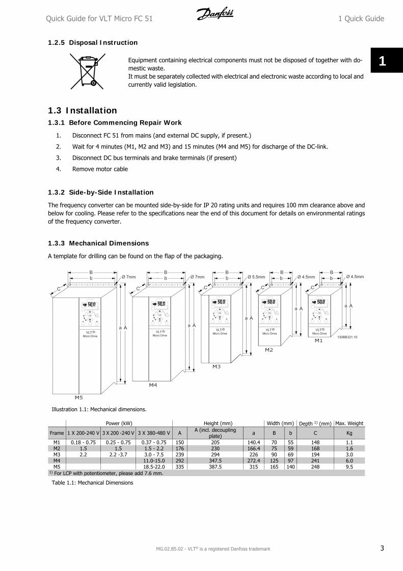
1.3.3 Mechanical Dimensions
A template for drilling can be found on the flap of the packaging.
Illustration 1.1: Mechanical dimensions.
Power (kW) Height (mm) Width (mm) Depth 1) (mm) Max. Weight
Frame 1 X 200-240 V 3 X 200 -240 V 3 X 380-480 V A A (incl. decouplingplate) a B b C Kg
M1 0.18 - 0.75 0.25 - 0.75 0.37 - 0.75 150 205 140.4 70 55 148 1.1M2 1.5 1.5 1.5 - 2.2 176 230 166.4 75 59 168 1.6M3 2.2 2.2 -3.7 3.0 - 7.5 239 294 226 90 69 194 3.0M4 11.0-15.0 292 347.5 272.4 125 97 241 6.0M5 18.5-22.0 335 387.5 315 165 140 248 9.5
1) For LCP with potentiometer, please add 7.6 mm.
Table 1.1: Mechanical Dimensions
Quick Guide for VLT Micro FC 51 1 Quick Guide
MG.02.B5.02 - VLT® is a registered Danfoss trademark 3
1
1.3.4 Electrical Installation in General
All cabling must comply with national and local regulations on cable cross-sections and ambient tem-perature. Copper conductors required, (60-75° C) recommended.
Details of terminal tightening torques. Power (kW) Torque (Nm)Frame 1 x 200-240 V 3 x 200-240 V 3 x 380-480 V Line Motor DC connection/Brake Control Terminals Earth Relay
M1 0.18 - 0.75 0.25 - 0.75 0.37 - 0.75 1.4 0.7 Spade1) 0.15 3 0.5M2 1.5 1.5 1.5 - 2.2 1.4 0.7 Spade1) 0.15 3 0.5M3 2.2 2.2 - 3.7 3.0 - 7.5 1.4 0.7 Spade1) 0.15 3 0.5M4 11.0-15.0 1.25 1.25 1.25 0.15 3 0.5M5 18.5-22.0 1.25 1.25 1.25 0.15 3 0.5
1) Spade connectors (6.3 mm Faston plugs)
Table 1.2: Tightening of terminals.
1.3.5 Fuses
Branch circuit protection:In order to protect the installation against electrical and fire hazard, all branch circuits in an installation, switch gear,machines etc., must be short-circuited and overcurrent protected according to national/international regulations.
Short circuit protection:Danfoss recommends using the fuses mentioned in the following tables to protect service personnel or other equipmentin case of an internal failure in the unit or short-circuit on DC-link. The frequency converter provides full short circuitprotection in case of a short-circuit on the motor or brake output.
Overcurrent protection:Provide overload protection to avoid overheating of the cables in the installation. Overcurrent protection must alwaysbe carried out according to national regulations. Fuses must be designed for protection in a circuit capable of supplyinga maximum of 100,000 Arms (symmetrical), 480 V maximum.
Non UL compliance:If UL/cUL is not to be complied with, Danfoss recommends using the fuses mentioned in the below table, which willensure compliance with EN50178/IEC61800-5-1:In case of malfunction, not following the fuse recommendation may result in damage to the frequency converter.
FC 51UL
Max. fuses non ULBussmann Bussmann Bussmann Littel fuse Ferraz-Shawmut
Ferraz-Shawmut
1 X 200-240 VkW Type RK1 Type J Type T Type RK1 Type CC Type RK1 Type gG0K18 - 0K37 KTN-R15 JKS-15 JJN-15 KLN-R15 ATM-R15 A2K-15R 16A0K75 KTN-R25 JKS-25 JJN-25 KLN-R25 ATM-R25 A2K-25R 25A1K5 KTN-R35 JKS-35 JJN-35 KLN-R35 - A2K-35R 35A2K2 KTN-R45 JKS-45 JJN-45 KLN-R45 - A2K-45R 40A3 x 200-240 V0K25 KTN-R10 JKS-10 JJN-10 KLN-R10 ATM-R10 A2K-10R 10A0K37 KTN-R15 JKS-15 JJN-15 KLN-R15 ATM-R15 A2K-15R 16A0K75 KTN-R20 JKS-20 JJN-20 KLN-R20 ATM-R20 A2K-20R 20A1K5 KTN-R25 JKS-25 JJN-25 KLN-R25 ATM-R25 A2K-25R 25A2K2 KTN-R40 JKS-40 JJN-40 KLN-R40 ATM-R40 A2K-40R 40A3K7 KTN-R40 JKS-40 JJN-40 KLN-R40 - A2K-40R 40A3 x 380-480 V0K37 - 0K75 KTS-R10 JKS-10 JJS-10 KLS-R10 ATM-R10 A6K-10R 10A1K5 KTS-R15 JKS-15 JJS-15 KLS-R15 ATM-R15 A2K-15R 16A2K2 KTS-R20 JKS-20 JJS-20 KLS-R20 ATM-R20 A6K-20R 20A3K0 KTS-R40 JKS-40 JJS-40 KLS-R40 ATM-R40 A6K405R 40A4K0 KTS-R40 JKS-40 JJS-40 KLS-R40 ATM-R40 A6K-40R 40A5K5 KTS-R40 JKS-40 JJS-40 KLS-R40 - A6K-40R 40A7K5 KTS-R40 JKS-40 JJS-40 KLS-R40 - A6K-40R 40A11K0 KTS-R60 JKS-60 JJS-60 KLS-R60 - A6K-60R 63A15K0 KTS-R60 JKS-60 JJS-60 KLS-R60 - A6K-60R 63A18K5 KTS-R60 JKS-60 JJS-60 KLS-R60 - A6K-60R 80A22K0 KTS-R60 JKS-60 JJS-60 KLS-R60 - A6K-60R 80A
Table 1.3: Fuses
1 Quick Guide Quick Guide for VLT Micro FC 51
4 MG.02.B5.02 - VLT® is a registered Danfoss trademark
1
1.3.6 Connecting to Mains and Motor
The frequency converter is designed to operate all standard three-phased asynchronous motors.The frequency converter is designed to accept mains/motor cables with a maximum cross-section of 4 mm2/10 AWG(M1, M2 and M3) and maximum cross-section 16 mm2/6 AWG (M4 and M5).
• Use a shielded/armored motor cable to comply with EMC emission specifications, and connect this cable toboth the decoupling plate and the motor metal.
• Keep motor cable as short as possible to reduce the noise level and leakage currents.
• For further details on mounting of the decoupling plate, please see instruction MI.02.BX.YY.
• Also see EMC-Correct Installation in Operating Instruction MG.02.AX.YY.
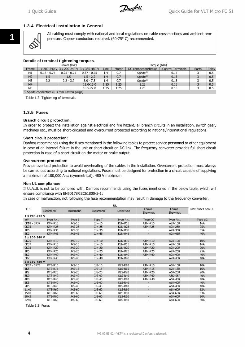
Step 1: First, mount the earth wires to earth terminal.
Step 2: Connect motor to terminals U, V and W.
Step 3: Mount mains supply to terminals L1/L, L2 andL3/N (3-phase) or L1/L and L3/N (single-phase) andtighten.
Illustration 1.2: Mounting of earth cable, mains and motorwires.
1.3.7 Control Terminals
All control cable terminals are located underneath theterminal cover in front of the frequency converter. Re-move the terminal cover using a screwdriver.
See back of terminal cover for outlines ofcontrol terminals and switches.
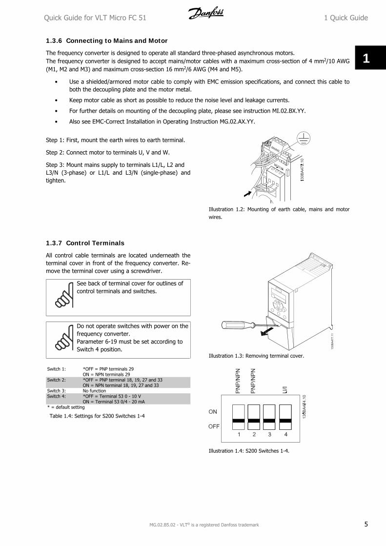
Do not operate switches with power on thefrequency converter.Parameter 6-19 must be set according toSwitch 4 position.
Illustration 1.3: Removing terminal cover.
Switch 1: *OFF = PNP terminals 29ON = NPN terminals 29
Switch 2: *OFF = PNP terminal 18, 19, 27 and 33ON = NPN terminal 18, 19, 27 and 33
Switch 3: No functionSwitch 4: *OFF = Terminal 53 0 - 10 V
ON = Terminal 53 0/4 - 20 mA* = default setting
Table 1.4: Settings for S200 Switches 1-4
Illustration 1.4: S200 Switches 1-4.
Quick Guide for VLT Micro FC 51 1 Quick Guide
MG.02.B5.02 - VLT® is a registered Danfoss trademark 5
1
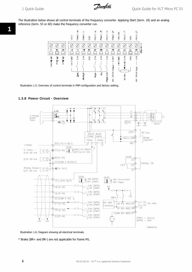
The illustration below shows all control terminals of the frequency converter. Applying Start (term. 18) and an analogreference (term. 53 or 60) make the frequency converter run.
Illustration 1.5: Overview of control terminals in PNP-configuration and factory setting.
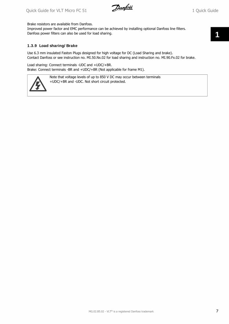
1.3.8 Power Circuit - Overview
Illustration 1.6: Diagram showing all electrical terminals.
* Brake (BR+ and BR-) are not applicable for frame M1.
1 Quick Guide Quick Guide for VLT Micro FC 51
6 MG.02.B5.02 - VLT® is a registered Danfoss trademark
1
Brake resistors are available from Danfoss.Improved power factor and EMC performance can be achieved by installing optional Danfoss line filters.Danfoss power filters can also be used for load sharing.
1.3.9 Load sharing/Brake
Use 6.3 mm insulated Faston Plugs designed for high voltage for DC (Load Sharing and brake).Contact Danfoss or see instruction no. MI.50.Nx.02 for load sharing and instruction no. MI.90.Fx.02 for brake.
Load sharing: Connect terminals -UDC and +UDC/+BR.Brake: Connect terminals -BR and +UDC/+BR (Not applicable for frame M1).
Note that voltage levels of up to 850 V DC may occur between terminals+UDC/+BR and -UDC. Not short circuit protected.
Quick Guide for VLT Micro FC 51 1 Quick Guide
MG.02.B5.02 - VLT® is a registered Danfoss trademark 7
1
1.4 Programming1.4.1 Programming with LCP
For detailed information on programming, please see Programming Guide, MG.02.CX.YY.
NB!The frequency converter can also be programmed from a PC via RS485 com-port by installing the MCT-10Set-up Software.This software can either be ordered using code number 130B1000 or downloaded from the Danfoss Website: www.danfoss.com/BusinessAreas/DrivesSolutions/softwaredownload
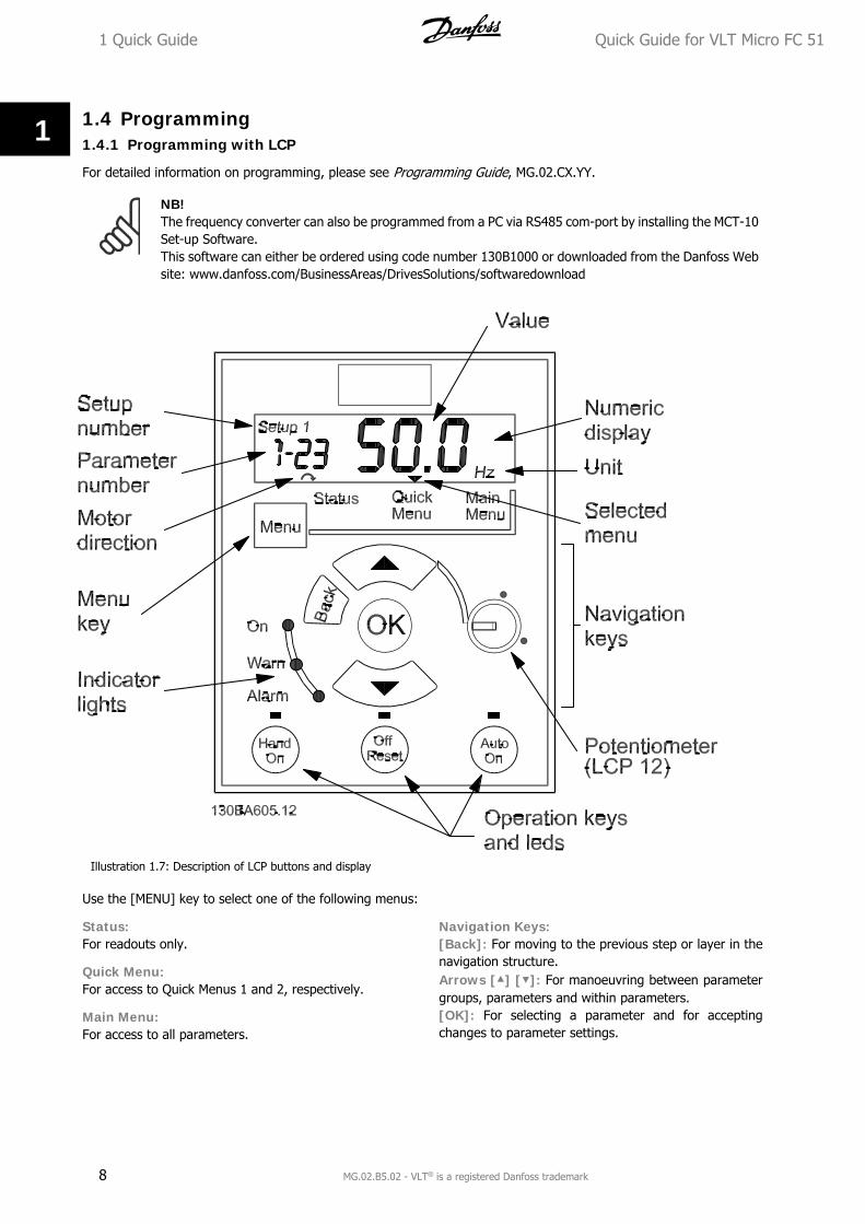
Illustration 1.7: Description of LCP buttons and display
Use the [MENU] key to select one of the following menus:
Status:For readouts only.
Quick Menu:For access to Quick Menus 1 and 2, respectively.
Main Menu:For access to all parameters.
Navigation Keys:[Back]: For moving to the previous step or layer in thenavigation structure.Arrows [] []: For manoeuvring between parametergroups, parameters and within parameters.[OK]: For selecting a parameter and for acceptingchanges to parameter settings.
1 Quick Guide Quick Guide for VLT Micro FC 51
8 MG.02.B5.02 - VLT® is a registered Danfoss trademark
1
Operation Keys:A yellow light above the operation keys indicates the active key.[Hand on]: Starts the motor and enables control of the frequency converter via the LCP.[Off/Reset]: Stops the motor (off). If in alarm mode the alarm will be reset.[Auto on]: The frequency converter is controlled either via control terminals or serial communication.[Potentiometer] (LCP12): The potentiometer works in two ways depending on the mode in which the frequencyconverter is running.In Auto Mode the potentiometer acts as an extra programmable analog input.In Hand on Mode the potentiometer controls local reference.
Arrows [] and [] toggles between the choices in each menu.
The display indicates the status mode with a small arrow above “Status”.
The Quick Menu gives easy access to the most frequently used parameters.
1. To enter the Quick Menu, press [MENU] key until indicator in display is placed above Quick Menu.
2. Use [] [] to select either QM1 or QM2, then press [OK].
3. Use [] [] to browse through the parameters in the Quick Menu.
4. Press [OK] to select a parameter.
5. Use [] [] to change the value of a parameter setting.
6. Press [OK] to accept the change.
7. To exit, press either [Back] twice to enter Status, or press [Menu] once to enter Main Menu.
No Name Range Default Function1-20 Motor Power [kW]/[HP] [0.09kW/0.12HP -30kW/40HP] Unit dependent Enter motor power from nameplate data1-22 Motor Voltage [50 - 999V] 230/400 Enter motor voltage from nameplate data1-23 Motor Frequency [20 - 400 Hz] 50 Enter motor frequency form nameplate data1-24 Motor Current [0.01 - 100.00 A] Unit dependent Enter motor current from nameplate data1-25 Motor nominal speed [100 - 9999 RPM] Unit dependent Enter motor nominal speed from nameplate data1-29 Automatic Motor Tuning
(AMT)[0] = off[2] = Enable AMT
[0] = off Use AMT to optimize motor performance.1. Stop VLT2. Choose [2]3. "Hand On"
3-02 Minimum reference [-4999 - 4999] 0 Enter value for minimum reference3-03 Maximum reference [-4999 - 4999] 50.00 Enter value for maximum reference3-41 Ramp up time 1 [0.05 - 3600s] 3.00 (10.001)) Ramp up time from 0 to rated motor frequency par. 1-233-42 Ramp down time 1 [0.05 - 3600s] 3.00 (10.001)) Ramp down time form rated motor frequency par. 1-23
to 01) M4 and M5 only
Table 1.5: Basic Settings Quick Menu 1
The Main Menu gives access to all parameters.
1. To enter the Main Menu, press [MENU] key until indicator in display is placed above Main Menu.
2. Use [] [] to browse through the parameter groups.
3. Press [OK] to select a parameter group.
4. Use [] [] to browse through the parameters in the specific group.
5. Press [OK] to select the parameter.
6. Use [] [] to set/change the parameter value.
7. Press [OK] to accept the value.
8. To exit, press either [Back] twice to enter Quick Menu, or press [Menu] once to enter Status.
Quick Guide for VLT Micro FC 51 1 Quick Guide
MG.02.B5.02 - VLT® is a registered Danfoss trademark 9
1
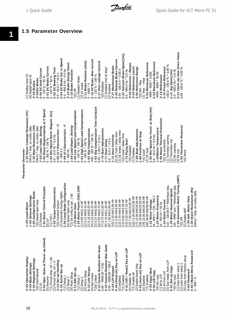
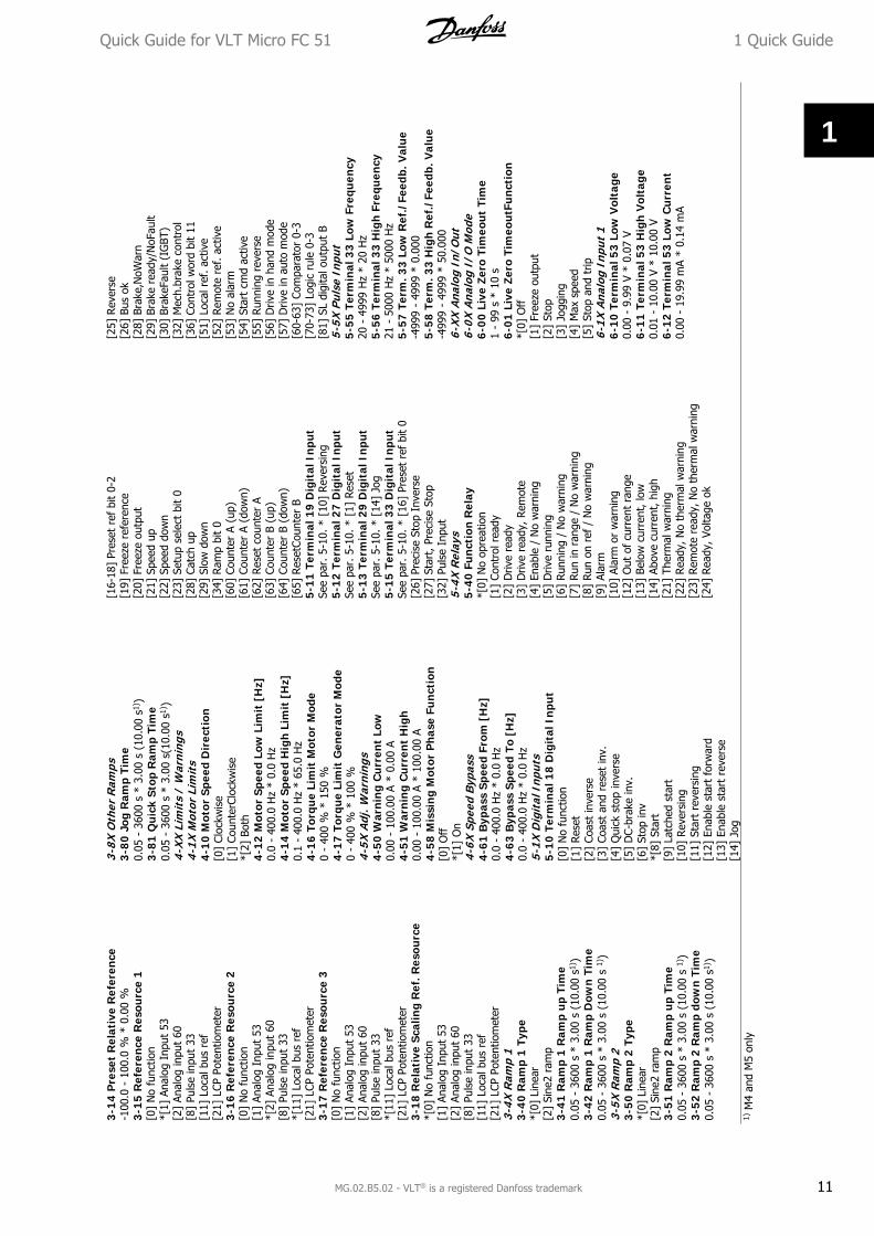
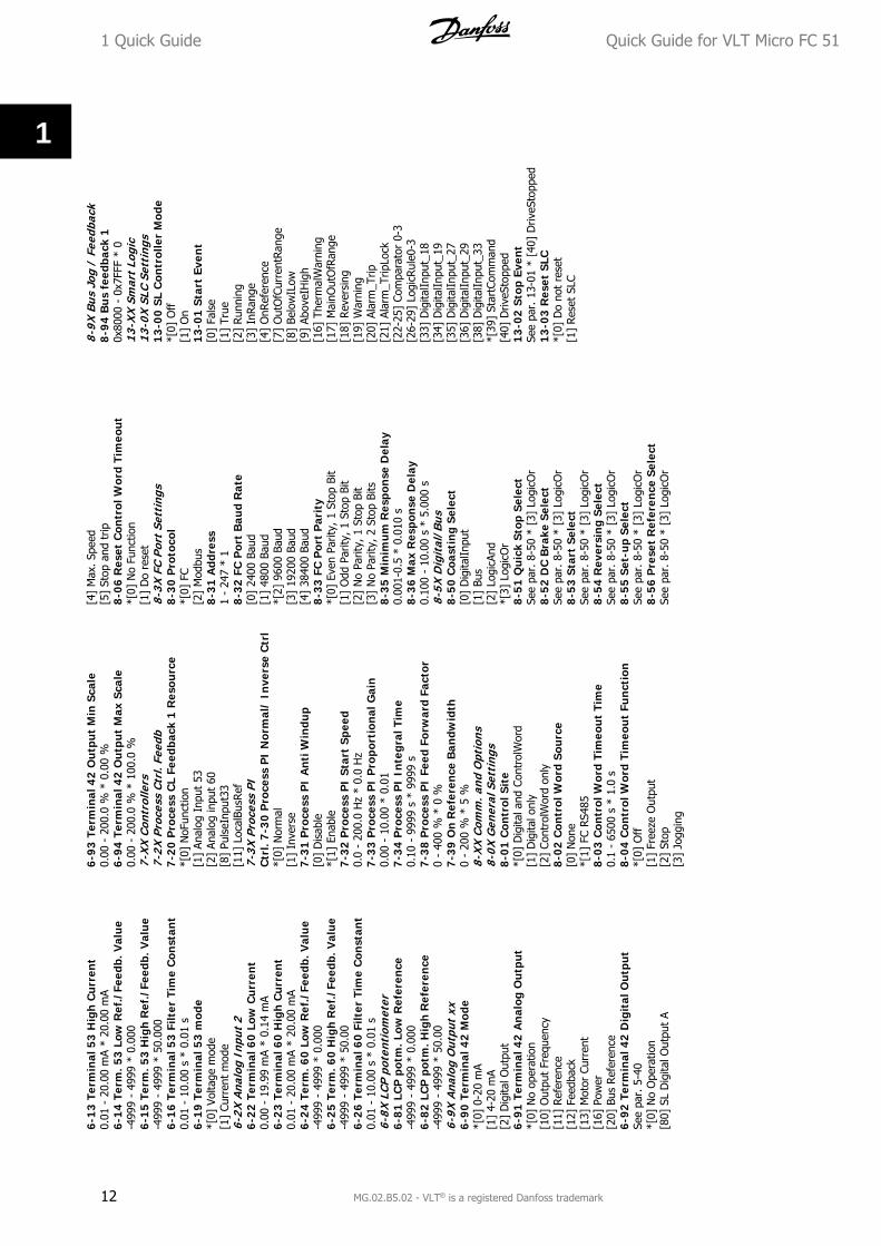
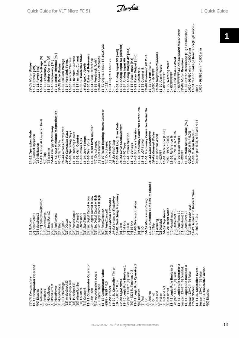
1.5 Parameter Overview
Par
amet
er O
verw
iev
0-X
X O
pera
tion
/Dis
play
0-0X
Bas
ic S
etti
ngs
0-0
3 R
egio
nal
Set
tin
gs*[
0] I
nter
natio
nal
[1]
US
0-04
Ope
r. S
tate
at
Pow
er-u
p (H
and)
[0]
Res
ume
*[1]
For
ced
stop
, re
f =
old
[2]
Forc
ed s
top,
ref
= 0
0-1X
Set
-up
Han
dlin
g0-
10
Act
ive
Set-
up
*[1]
Set
up 1
[2]
Setu
p 2
[9]
Mul
ti Se
tup
0-1
1 Ed
it S
et-u
p*[
1] S
etup
1[2
] Se
tup
2[9
] Ac
tive
Setu
p0-
12
Link
Set
ups
[0]
Not
Lin
ked
*[20
] Li
nked
0-31
Cu
stom
Rea
dou
t M
in S
cale
0.00
– 9
999.
00 *
0.0
00-
32 C
ust
om R
eado
ut
Max
Sca
le0.
00 –
999
9.00
* 1
00.0
0-4X
LCP
Key
pad
0-4
0 [H
and
on]
Key
on
LC
P[0
] D
isab
led
*[1]
Ena
bled
0-4
1 [O
ff /
Res
et]
Key
on
LC
P[0
] D
isab
le A
ll*[
1] E
nabl
e Al
l[2
] En
able
Res
et O
nly
0-42
[A
uto
on
] K
ey o
n L
CP
[0]
Dis
able
d*[
1] E
nabl
ed0-
5X C
opy/
Save
0-5
0 LC
P C
opy
*[0]
No
copy
[1]
All t
o LC
P[2
] Al
l fro
m L
CP[3
] Si
ze in
dep.
fro
m L
CP0-
51
Set-
up
Cop
y*[
0] N
o co
py[1
] Co
py f
rom
set
up 1
[2]
Copy
fro
m s
etup
2[9
] Co
py f
rom
Fac
tory
set
up0-
6X P
assw
ord
0-60
(M
ain
) M
enu
Pas
swor
d0
- 99
9 *
0
1-X
X L
oad/
Mot
or1-
0X G
ener
al S
etti
ngs
1-0
0 C
onfi
gura
tion
Mod
e*[
0] S
peed
ope
n lo
op[3
] Pr
oces
s1-
01 M
otor
Con
trol
Pri
nci
ple
[0]
U/f
*[1]
VVC
+1-
03 T
orqu
e C
har
acte
rist
ics
*[0]
Con
stan
t to
rque
[2]
Auto
mat
ic E
nerg
y O
ptim
.1
-05
Loca
l Mod
e C
onfi
gura
tion
[0]
Spee
d O
pen
Loop
*[2]
As
conf
ig in
par
. 1-
001-
2X M
otor
Dat
a1-
20 M
otor
Pow
er [
kW]
[HP
][1
] 0.
09 k
W/0
.12
HP
[2]
0.12
kW
/0.1
6 H
P[3
] 0.
18 k
W/0
.25
HP
[4]
0.25
kW
/0.3
3 H
P[5
] 0.
37 k
W/0
.50
HP
[6]
0.55
kW
/0.7
5 H
P[7
] 0.
75 k
W/1
.00
HP
[8]
1.10
kW
/1.5
0 H
P[9
] 1.
50 k
W/2
.00
HP
[10]
2.2
0 kW
/3.0
0 H
P[1
1] 3
.00
kW/4
.00
HP
[12]
3.7
0 kW
/5.0
0 H
P[1
3] 4
.00
kW/5
.40
HP
[14]
5.5
0 kW
/7.5
0 H
P[1
5] 7
.50
kW/1
0.00
HP
[16]
11.
00 k
W/1
5.00
HP
[17]
15.
00 k
W/2
0.00
HP
[18]
18.
50 k
W/2
5.00
HP
[19]
22.
00 k
W/2
9.50
HP
[20]
30.
00 k
W/4
0.00
HP
1-2
2 M
otor
Vol
tage
50 -
999
V *
230
- 4
00 V
1-23
Mot
or F
requ
ency
20 -
400
Hz
* 50
Hz
1-24
Mot
or C
urr
ent
0.01
- 1
00.0
0 A
* M
otor
type
dep
.1
-25
Mot
or N
omin
al S
peed
100
- 99
99 r
pm *
Mot
orty
pe d
ep.
1-2
9 A
utom
atic
Mot
or T
unin
g (A
MT)
*[0]
Off
[2]
Enab
le A
MT
1-3X
Adv
. Mot
or D
ata
1-3
0 St
ator
Res
ista
nce
(R
s)[O
hm]
* D
ep. o
n m
otor
dat
a
1-3
3 St
ator
Lea
kage
Rea
ctan
ce (
X1
)[O
hm]
* D
ep. o
n m
otor
dat
a1
-35
Mai
n R
eact
ance
(X
h)
[Ohm
] *
Dep
. on
mot
or d
ata
1-5X
Loa
d In
dep.
Set
ting
1-5
0 M
otor
Mag
neti
sati
on a
t 0
Spe
ed0
- 30
0 %
* 1
00 %
1-5
2 M
in S
peed
Nor
m. M
agn
et. [
Hz]
0.0
- 10
.0 H
z *
0.0
Hz
1-5
5 U
/f C
hara
cter
isti
c -
U0
- 99
9.9
V1-
56
U/f
Cha
ract
eris
tic
- F
0 -
400
Hz
1-6X
Loa
d D
epen
. Set
ting
1-6
0 Lo
w S
peed
Loa
d C
ompe
nsat
ion
0 -
199
% *
100
%1-
61
Hig
h S
peed
Loa
d C
ompe
nsat
ion
0 -
199
% *
100
%1-
62
Slip
Com
pen
sati
on-4
00 -
399
% *
100
%1-
63
Slip
Com
pen
sati
on T
ime
Con
stan
t0.
05 -
5.0
0 s
* 0.
10 s
1-7X
Sta
rt A
djus
tmen
ts1-
71
Star
t D
elay
0.0
- 10
.0 s
* 0
.0 s
1-7
2 St
art
Fun
ctio
n[0
] D
C ho
ld /
del
ay t
ime
[1]
DC
brak
e /
dela
y tim
e*[
2] C
oast
/ d
elay
tim
e1-
73
Flyi
ng
Star
t*[
0] D
isab
led
[1]
Enab
led
1-8X
Sto
p A
djus
tmen
ts1
-80
Fu
ncti
on a
t S
top
*[0]
Coa
st[1
] D
C ho
ld1-
82
Min
Spe
ed f
or F
un
ct. a
t S
top
[Hz]
0.0
- 20
.0 H
z *
0.0
Hz
1-9X
Mot
or T
empe
ratu
re1-
90
Mot
or T
her
mal
Pro
tect
ion
*[0]
No
prot
ectio
n[1
] Te
rmis
tor
war
ning
[2]
Ther
mis
tor
trip
[3]
Etr
war
ning
[4]
Etr
trip
1-9
3 Th
erm
isto
r R
esou
rce
*[0]
Non
e
[1]
Anal
og in
put
53[6
] D
igita
l inp
ut 2
92-
XX
Bra
kes
2-0X
DC-
Bra
ke2
-00
DC
Hol
d C
urr
ent
0 -
150
% *
50
%2
-01
DC
Bra
ke C
urr
ent
0 -
150
% *
50
%2
-02
DC
Bra
kin
g Ti
me
0.0
- 60
.0 s
* 1
0.0
s2-
04 D
C B
rake
Cu
t In
Spe
ed0.
0 -
400.
0 H
z *
0.0
Hz
2-1X
Bra
ke E
nerg
y Fu
nct.
2-1
0 B
rake
Fu
nct
ion
*[0]
Off
[1]
Res
isto
r br
ake
[2]
AC b
rake
2-1
1 B
rake
Res
isto
r (o
hm
)5
- 50
00 *
52
-16
AC
Bra
ke, M
ax c
urr
ent
0 -
150
% *
100
%2
-17
Ove
r-vo
ltag
e C
ontr
ol*[
0] D
isab
led
[1]
Enab
led
(not
at
stop
)[2
] En
able
d2-
2* M
echa
nica
l Bra
ke2-
20 R
elea
se B
rake
Cu
rren
t0.
00 -
100
.0 A
* 0
.00
A2
-22
Act
ivat
e B
rake
Spe
ed [
Hz]
0.0
- 40
0.0
Hz
* 0.
0 H
z3-
XX
Ref
eren
ce /
Ram
ps3-
0X R
efer
ence
Lim
its
3-0
0 R
efer
ence
Ran
ge*[
0] M
in -
Max
[1]
-Max
- +
Max
3-0
2 M
inim
um R
efer
ence
-499
9 -
4999
* 0
.000
3-0
3 M
axim
um
Ref
eren
ce-4
999
- 49
99 *
50.
003-
1X R
efer
ence
s3-
10 P
rese
t R
efer
ence
-100
.0 -
100
.0 %
* 0
.00
%3
-11
Jog
Spee
d [H
z]0.
0 -
400.
0 H
z *
5.0
Hz
3-1
2 C
atch
up/
slow
Dow
n V
alu
e0.
00 -
100
.0 %
* 0
.00
%
1 Quick Guide Quick Guide for VLT Micro FC 51
10 MG.02.B5.02 - VLT® is a registered Danfoss trademark
1
3-1
4 P
rese
t R
elat
ive
Ref
eren
ce-1
00.0
- 1
00.0
% *
0.0
0 %
3-1
5 R
efer
ence
Res
ourc
e 1
[0]
No
func
tion
*[1]
Ana
log
Inpu
t 53
[2]
Anal
og in
put
60[8
] Pu
lse
inpu
t 33
[11]
Loc
al b
us r
ef[2
1] L
CP P
oten
tiom
eter
3-1
6 R
efer
ence
Res
ourc
e 2
[0]
No
func
tion
[1]
Anal
og I
nput
53
*[2]
Ana
log
inpu
t 60
[8]
Puls
e in
put
33*[
11]
Loca
l bus
ref
[21]
LCP
Pot
entio
met
er3-
17
Ref
eren
ce R
esou
rce
3[0
] N
o fu
nctio
n[1
] An
alog
Inp
ut 5
3[2
] An
alog
inpu
t 60
[8]
Puls
e in
put
33*[
11]
Loca
l bus
ref
[21]
LCP
Pot
entio
met
er3-
18
Rel
ativ
e Sc
alin
g R
ef. R
esou
rce
*[0]
No
func
tion
[1]
Anal
og I
nput
53
[2]
Anal
og in
put
60[8
] Pu
lse
inpu
t 33
[11]
Loc
al b
us r
ef[2
1] L
CP P
oten
tiom
eter
3-4X
Ram
p 1
3-4
0 R
amp
1 Ty
pe*[
0] L
inea
r[2
] Si
ne2
ram
p3-
41
Ram
p 1
Ram
p u
p Ti
me
0.05
- 3
600
s *
3.00
s (
10.0
0 s1
) )3-
42
Ram
p 1
Ram
p D
own
Tim
e0.
05 -
360
0 s
* 3.
00 s
(10
.00
s 1)
)3-
5X R
amp
23-
50
Ram
p 2
Type
*[0]
Lin
ear
[2]
Sine
2 ra
mp
3-5
1 R
amp
2 R
amp
up
Tim
e0.
05 -
360
0 s
* 3.
00 s
(10
.00
s 1)
)3-
52
Ram
p 2
Ram
p do
wn
Tim
e0.
05 -
360
0 s
* 3.
00 s
(10
.00
s1) )
3-8X
Oth
er R
amps
3-8
0 Jo
g R
amp
Tim
e0.
05 -
360
0 s
* 3.
00 s
(10
.00
s1) )
3-8
1 Q
uick
Sto
p R
amp
Tim
e0.
05 -
360
0 s
* 3.
00 s
(10.
00 s
1))
4-X
X L
imit
s /
War
ning
s4-
1X M
otor
Lim
its
4-10
Mot
or S
peed
Dir
ecti
on[0
] Cl
ockw
ise
[1]
Coun
terC
lock
wis
e*[
2] B
oth
4-12
Mot
or S
peed
Low
Lim
it [
Hz]
0.0
- 40
0.0
Hz
* 0.
0 H
z4-
14 M
otor
Spe
ed H
igh
Lim
it [
Hz]
0.1
- 40
0.0
Hz
* 65
.0 H
z4
-16
Torq
ue
Lim
it M
otor
Mod
e0
- 40
0 %
* 1
50 %
4-17
Tor
que
Lim
it G
ener
ator
Mod
e0
- 40
0 %
* 1
00 %
4-5X
Adj
. War
ning
s4
-50
War
nin
g C
urr
ent
Low
0.00
- 1
00.0
0 A
* 0.
00 A
4-5
1 W
arni
ng
Cu
rren
t H
igh
0.00
- 1
00.0
0 A
* 10
0.00
A4
-58
Mis
sin
g M
otor
Pha
se F
unc
tion
[0]
Off
*[1]
On
4-6X
Spe
ed B
ypas
s4
-61
Byp
ass
Spee
d Fr
om [
Hz]
0.0
- 40
0.0
Hz
* 0.
0 H
z4
-63
Byp
ass
Spee
d To
[H
z]0.
0 -
400.
0 H
z *
0.0
Hz
5-1X
Dig
ital
Inp
uts
5-1
0 Te
rmin
al 1
8 D
igit
al I
npu
t[0
] N
o fu
nctio
n[1
] Re
set
[2]
Coas
t in
vers
e[3
] Co
ast
and
rese
t in
v.[4
] Q
uick
sto
p in
vers
e[5
] D
C-br
ake
inv.
[6]
Stop
inv
*[8]
Sta
rt[9
] La
tche
d st
art
[10]
Rev
ersi
ng[1
1] S
tart
rev
ersi
ng[1
2] E
nabl
e st
art
forw
ard
[13]
Ena
ble
star
t re
vers
e[1
4] J
og
[16-
18]
Pres
et r
ef b
it 0-
2[1
9] F
reez
e re
fere
nce
[20]
Fre
eze
outp
ut[2
1] S
peed
up
[22]
Spe
ed d
own
[23]
Set
up s
elec
t bi
t 0
[28]
Cat
ch u
p[2
9] S
low
dow
n[3
4] R
amp
bit
0[6
0] C
ount
er A
(up
)[6
1] C
ount
er A
(do
wn)
[62]
Res
et c
ount
er A
[63]
Cou
nter
B (
up)
[64]
Cou
nter
B (
dow
n)[6
5] R
eset
Coun
ter
B5
-11
Term
inal
19
Dig
ital
In
put
See
par.
5-1
0. *
[10
] Rev
ersi
ng5
-12
Term
inal
27
Dig
ital
In
put
See
par.
5-1
0. *
[1]
Res
et5
-13
Term
inal
29
Dig
ital
In
put
See
par.
5-1
0. *
[14
] Jo
g5
-15
Term
inal
33
Dig
ital
In
put
See
par.
5-1
0. *
[16
] Pr
eset
ref
bit
0[2
6] P
reci
se S
top
Inve
rse
[27]
Sta
rt, Pr
ecis
e St
op[3
2] P
ulse
Inp
ut5-
4X R
elay
s5
-40
Fun
ctio
n R
elay
*[0]
No
opre
atio
n[1
] Co
ntro
l rea
dy[2
] D
rive
read
y[3
] D
rive
read
y, R
emot
e[4
] En
able
/ N
o w
arni
ng[5
] D
rive
runn
ing
[6]
Runn
ing
/ N
o w
arni
ng[7
] Ru
n in
ran
ge /
No
war
ning
[8]
Run
on r
ef /
No
war
ning
[9]
Alar
m[1
0] A
larm
or
war
ning
[12]
Out
of
curr
ent
rang
e[1
3] B
elow
cur
rent
, lo
w[1
4] A
bove
cur
rent
, hig
h[2
1] T
herm
al w
arni
ng[2
2] R
eady
, No
ther
mal
war
ning
[23]
Rem
ote
read
y, N
o th
erm
al w
arni
ng[2
4] R
eady
, Vol
tage
ok
[25]
Rev
erse
[26]
Bus
ok
[28]
Bra
ke,N
oWar
n[2
9] B
rake
rea
dy/N
oFau
lt[3
0] B
rake
Faul
t (I
GBT
)[3
2] M
ech.
brak
e co
ntro
l[3
6] C
ontr
ol w
ord
bit
11[5
1] L
ocal
ref
. ac
tive
[52]
Rem
ote
ref. a
ctiv
e[5
3] N
o al
arm
[54]
Sta
rt c
md
activ
e[5
5] R
unni
ng r
ever
se[5
6] D
rive
in h
and
mod
e[5
7] D
rive
in a
uto
mod
e[6
0-63
] Co
mpa
rato
r 0-
3[7
0-73
] Lo
gic
rule
0-3
[81]
SL
digi
tal o
utpu
t B
5-5X
Pul
se I
nput
5-5
5 Te
rmin
al 3
3 Lo
w F
requ
ency
20 -
499
9 H
z *
20 H
z5
-56
Term
inal
33
Hig
h F
requ
ency
21 -
500
0 H
z *
5000
Hz
5-5
7 Te
rm. 3
3 Lo
w R
ef./
Feed
b. V
alu
e-4
999
- 49
99 *
0.0
005
-58
Term
. 33
Hig
h R
ef./
Feed
b. V
alu
e-4
999
- 49
99 *
50.
000
6-X
X A
nalo
g In
/Out
6-0X
Ana
log
I/O
Mod
e6
-00
Live
Zer
o Ti
meo
ut T
ime
1 -
99 s
* 1
0 s
6-0
1 Li
ve Z
ero
Tim
eout
Fun
ctio
n*[
0] O
ff[1
] Fr
eeze
out
put
[2]
Stop
[3]
Jogg
ing
[4]
Max
spe
ed[5
] St
op a
nd t
rip6-
1X A
nalo
g In
put
16
-10
Term
inal
53
Low
Vol
tage
0.00
- 9
.99
V *
0.07
V6
-11
Term
inal
53
Hig
h V
olta
ge0.
01 -
10.
00 V
* 1
0.00
V6
-12
Term
inal
53
Low
Cur
ren
t0.
00 -
19.
99 m
A *
0.14
mA
1) M
4 an
d M
5 on
ly
Quick Guide for VLT Micro FC 51 1 Quick Guide
MG.02.B5.02 - VLT® is a registered Danfoss trademark 11
1
6-1
3 Te
rmin
al 5
3 H
igh
Cur
rent
0.01
- 2
0.00
mA
* 20
.00
mA
6-1
4 Te
rm. 5
3 L
ow R
ef./
Feed
b. V
alu
e-4
999
- 49
99 *
0.0
006-
15
Term
. 53
Hig
h R
ef./
Feed
b. V
alu
e-4
999
- 49
99 *
50.
000
6-1
6 Te
rmin
al 5
3 F
ilter
Tim
e C
onst
ant
0.01
- 1
0.00
s *
0.0
1 s
6-1
9 Te
rmin
al 5
3 m
ode
*[0]
Vol
tage
mod
e[1
] Cu
rren
t m
ode
6-2X
Ana
log
Inpu
t 2
6-2
2 Te
rmin
al 6
0 L
ow C
urre
nt0.
00 -
19.
99 m
A *
0.14
mA
6-2
3 Te
rmin
al 6
0 H
igh
Cur
rent
0.01
- 2
0.00
mA
* 20
.00
mA
6-2
4 Te
rm. 6
0 L
ow R
ef./
Feed
b. V
alu
e-4
999
- 49
99 *
0.0
006-
25
Term
. 60
Hig
h R
ef./
Feed
b. V
alu
e-4
999
- 49
99 *
50.
006-
26
Term
inal
60
Filt
er T
ime
Con
stan
t0.
01 -
10.
00 s
* 0
.01
s6-
8X L
CP p
oten
tiom
eter
6-8
1 LC
P p
otm
. Low
Ref
eren
ce-4
999
- 49
99 *
0.0
006-
82
LCP
pot
m. H
igh
Ref
eren
ce-4
999
- 49
99 *
50.
006-
9X A
nalo
g O
utpu
t xx
6-9
0 Te
rmin
al 4
2 M
ode
*[0]
0-2
0 m
A[1
] 4-
20 m
A[2
] D
igita
l Out
put
6-9
1 Te
rmin
al 4
2 A
nal
og O
utp
ut*[
0] N
o op
erat
ion
[10]
Out
put
Freq
uenc
y[1
1] R
efer
ence
[12]
Fee
dbac
k[1
3] M
otor
Cur
rent
[16]
Pow
er[2
0] B
us R
efer
ence
6-9
2 Te
rmin
al 4
2 D
igit
al O
utpu
tSe
e pa
r. 5
-40
*[0]
No
Ope
ratio
n[8
0] S
L D
igita
l Out
put
A
6-93
Ter
min
al 4
2 O
utp
ut M
in S
cale
0.00
- 2
00.0
% *
0.0
0 %
6-94
Ter
min
al 4
2 O
utp
ut M
ax S
cale
0.00
- 2
00.0
% *
100
.0 %
7-X
X C
ontr
olle
rs7-
2X P
roce
ss C
trl.
Feed
b7-
20 P
roce
ss C
L Fe
edba
ck 1
Res
ourc
e*[
0] N
oFun
ctio
n[1
] An
alog
Inp
ut 5
3[2
] An
alog
inpu
t 60
[8]
Puls
eInp
ut33
[11]
Loc
alBu
sRef
7-3X
Pro
cess
PI
Ctr
l. 7-
30 P
roce
ss P
I N
orm
al/
Inve
rse
Ctr
l*[
0] N
orm
al[1
] In
vers
e7-
31 P
roce
ss P
I A
nti
Win
dup
[0]
Dis
able
*[1]
Ena
ble
7-32
Pro
cess
PI
Star
t Sp
eed
0.0
- 20
0.0
Hz
* 0.
0 H
z7-
33 P
roce
ss P
I P
ropo
rtio
nal
Gai
n0.
00 -
10.
00 *
0.0
17-
34 P
roce
ss P
I In
tegr
al T
ime
0.10
- 9
999
s *
9999
s7-
38 P
roce
ss P
I Fe
ed F
orw
ard
Fact
or0
- 40
0 %
* 0
%7-
39 O
n R
efer
ence
Ban
dwid
th0
- 20
0 %
* 5
%8-
XX
Com
m. a
nd O
ptio
ns8-
0X G
ener
al S
etti
ngs
8-01
Con
trol
Sit
e*[
0] D
igita
l and
Con
trol
Wor
d[1
] D
igita
l onl
y[2
] Co
ntro
lWor
d on
ly8-
02 C
ontr
ol W
ord
Sou
rce
[0]
Non
e*[
1] F
C RS
485
8-03
Con
trol
Wor
d Ti
meo
ut
Tim
e0.
1 -
6500
s *
1.0
s8-
04 C
ontr
ol W
ord
Tim
eout
Fu
ncti
on*[
0] O
ff[1
] Fr
eeze
Out
put
[2]
Stop
[3]
Jogg
ing
[4]
Max
. Sp
eed
[5]
Stop
and
trip
8-06
Res
et C
ontr
ol W
ord
Tim
eou
t*[
0] N
o Fu
nctio
n[1
] D
o re
set
8-3X
FC
Port
Set
ting
s8-
30 P
roto
col
*[0]
FC
[2]
Mod
bus
8-31
Add
ress
1 -
247
* 1
8-32
FC
Por
t B
aud
Rat
e[0
] 24
00 B
aud
[1]
4800
Bau
d*[
2] 9
600
Baud
[3]
1920
0 Ba
ud[4
] 38
400
Baud
8-33
FC
Por
t P
arit
y*[
0] E
ven
Parit
y, 1
Sto
p Bi
t[1
] O
dd P
arity
, 1 S
top
Bit
[2]
No
Parit
y, 1
Sto
p Bi
t[3
] N
o Pa
rity,
2 S
top
Bits
8-35
Min
imu
m R
espo
nse
Del
ay0.
001-
0.5
* 0.
010
s8-
36 M
ax R
espo
nse
Del
ay0.
100
- 10
.00
s *
5.00
0 s
8-5X
Dig
ital
/Bus
8-50
Coa
stin
g S
elec
t[0
] D
igita
lInpu
t[1
] Bu
s[2
] Lo
gicA
nd*[
3] L
ogic
Or
8-51
Qu
ick
Stop
Sel
ect
See
par.
8-5
0 *
[3]
Logi
cOr
8-52
DC
Bra
ke S
elec
tSe
e pa
r. 8
-50
* [3
] Lo
gicO
r8-
53 S
tart
Sel
ect
See
par.
8-5
0 *
[3]
Logi
cOr
8-54
Rev
ersi
ng
Sele
ctSe
e pa
r. 8
-50
* [3
] Lo
gicO
r8-
55 S
et-u
p Se
lect
See
par.
8-5
0 *
[3]
Logi
cOr
8-56
Pre
set
Ref
eren
ce S
elec
tSe
e pa
r. 8
-50
* [3
] Lo
gicO
r
8-9X
Bus
Jog
/ F
eedb
ack
8-9
4 B
us
feed
back
10x
8000
- 0
x7FF
F *
013
-XX
Sm
art
Logi
c13
-0X
SLC
Set
ting
s1
3-0
0 S
L C
ontr
olle
r M
ode
*[0]
Off
[1]
On
13-
01 S
tart
Eve
nt
[0]
Fals
e[1
] Tr
ue[2
] Ru
nnin
g[3
] In
Rang
e[4
] O
nRef
eren
ce[7
] O
utO
fCur
rent
Rang
e[8
] Be
low
ILow
[9]
Abov
eIH
igh
[16]
The
rmal
War
ning
[17]
Mai
nOut
OfR
ange
[18]
Rev
ersi
ng[1
9] W
arni
ng[2
0] A
larm
_Trip
[21]
Ala
rm_T
ripLo
ck[2
2-25
] Co
mpa
rato
r 0-
3[2
6-29
] Lo
gicR
ule0
-3[3
3] D
igita
lInpu
t_18
[34]
Dig
italIn
put_
19[3
5] D
igita
lInpu
t_27
[36]
Dig
italIn
put_
29[3
8] D
igita
lInpu
t_33
*[39
] St
artC
omm
and
[40]
Driv
eSto
pped
13-
02 S
top
Even
tSe
e pa
r. 1
3-01
* [
40]
Driv
eSto
pped
13-
03 R
eset
SLC
*[0]
Do
not
rese
t[1
] Res
et S
LC
1 Quick Guide Quick Guide for VLT Micro FC 51
12 MG.02.B5.02 - VLT® is a registered Danfoss trademark
1
13-1
X C
ompa
rato
rs13
-10
Com
para
tor
Ope
ran
d*[
0] D
isab
led
[1]
Refe
renc
e[2
] Fe
edba
ck[3
] M
otor
Spee
d[4
] M
otor
Curr
ent
[6]
Mot
orPo
wer
[7]
Mot
orVo
ltage
[8]
DCL
inkV
olta
ge[1
2] A
nalo
gInp
ut53
[13]
Ana
logI
nput
60[1
8] P
ulse
Inpu
t33
[20]
Ala
rmN
umbe
r[3
0] C
ount
erA
[31]
Cou
nter
B13
-11
Com
para
tor
Ope
rato
r[0
] Le
ss T
han
*[1]
App
roxi
mat
ely
equa
ls[2
] G
reat
er T
han
13-1
2 C
ompa
rato
r V
alu
e-9
999
- 99
99 *
0.0
13-2
X T
imer
s13
-20
SL
Con
trol
ler
Tim
er0.
0 -
3600
s *
0.0
s13
-4X
Log
ic R
ules
13-4
0 Lo
gic
Ru
le B
oole
an 1
See
par.
13-
01 *
[0]
Fal
se[3
0] -
[32
] SL
Tim
e-ou
t 0-
213
-41
Logi
c R
ule
Ope
rato
r 1
*[0]
Dis
able
d[1
] An
d[2
] O
r[3
] An
d no
t[4
] O
r no
t[5
] N
ot a
nd[6
] N
ot o
r[7
] N
ot a
nd n
ot[8
] N
ot o
r no
t13
-42
Logi
c R
ule
Boo
lean
2Se
e pa
r. 1
3-40
* [
0] F
alse
13-4
3 Lo
gic
Ru
le O
pera
tor
2Se
e pa
r. 1
3-41
* [
0] D
isab
led
13-4
4 Lo
gic
Ru
le B
oole
an 3
See
par.
13-
40 *
[0]
Fal
se13
-5X
Sta
tes
13-5
1 S
L C
ontr
olle
r Ev
ent
See
par.
13-
40 *
[0]
Fal
se13
-52
SL
Con
trol
ler
Act
ion
*[0]
Dis
able
d
[1]
NoA
ctio
n[2
] Se
lect
Setu
p1[3
] Se
lect
Setu
p2[1
0-17
] Se
lect
Pres
etRe
f0-7
[18]
Sel
ectR
amp1
[19]
Sel
ectR
amp2
[22]
Run
[23]
Run
Reve
rse
[24]
Sto
p[2
5] Q
stop
[26]
DCs
top
[27]
Coa
st[2
8] F
reez
eOut
put
[29]
Sta
rtTi
mer
0[3
0] S
tart
Tim
er1
[31]
Sta
rtTi
mer
2[3
2] S
et D
igita
l Out
put
A Lo
w[3
3] S
et D
igita
l Out
put
B Lo
w[3
8] S
et D
igita
l Out
put
A H
igh
[39]
Set
Dig
ital O
utpu
t B
Hig
h[6
0] R
eset
Coun
terA
[61]
Res
etCo
unte
rB14
-XX
Spe
cial
Fun
ctio
ns14
-0X
Inv
erte
r Sw
itch
ing
14-
01 S
wit
chin
g Fr
equ
ency
[0]
2 kH
z*[
1] 4
kH
z[2
] 8
kHz
[4]
16 k
Hz
14-
03 O
verm
odu
lati
on[0
] O
ff*[
1] O
n14
-1X
Mai
ns m
onit
orin
g1
4-12
Fu
nct
ion
at
mai
ns im
bala
nce
*[0]
Trip
[1]
War
ning
[2]
Dis
able
d14
-2X
Tri
p R
eset
14-
20 R
eset
Mod
e*[
0] M
anua
l res
et[1
-9]
Auto
Rese
t 1-
9[1
0] A
utoR
eset
10
[11]
Aut
oRes
et 1
5[1
2] A
utoR
eset
20
[13]
Inf
inite
aut
o re
set
14-
21 A
uto
mat
ic R
esta
rt T
ime
0 -
600
s *
10 s
14-
22 O
pera
tion
Mod
e*[
0] N
orm
al O
pera
tion
[2]
Initi
alis
atio
n1
4-26
Act
ion
At
Inve
rter
Fau
lt*[
0] T
rip[1
] W
arni
ng14
-4X
Ene
rgy
Opt
imis
ing
14-
41 A
EO M
inim
um
Mag
neti
sati
on40
- 7
5 %
* 6
6 %
15-X
X D
rive
Inf
orm
atio
n15
-0X
Ope
rati
ng D
ata
15-
00 O
pera
tin
g D
ays
15
-01
Ru
nni
ng
Hou
rs1
5-02
kW
h C
oun
ter
15-
03 P
ower
Ups
15-
04 O
ver
Tem
ps1
5-05
Ove
r V
olts
15-
06 R
eset
kW
h C
ount
er*[
0] D
o no
t re
set
[1]
Res
et c
ount
er1
5-0
7 R
eset
Ru
nn
ing
Hou
rs C
ount
er*[
0] D
o no
t re
set
[1]
Res
et c
ount
er15
-3X
Fau
lt L
og1
5-30
Fau
lt L
og:
Erro
r C
ode
15-4
X D
rive
Ide
ntif
icat
ion
15-
40 F
C T
ype
15-
41 P
ower
Sec
tion
15-
42 V
olta
ge1
5-43
Sof
twar
e V
ersi
on15
-46
Freq
uen
cy C
onve
rter
Ord
er. N
o1
5-48
LC
P I
d N
o15
-51
Freq
uen
cy C
onve
rter
Ser
ial N
o16
-XX
Dat
a R
eado
uts
16-0
X G
ener
al S
tatu
s1
6-00
Con
trol
Wor
d0
- 0X
FFFF
16-
01 R
efer
ence
[U
nit
]-4
999
- 49
99 *
0.0
001
6-02
Ref
eren
ce %
-200
.0 -
200
.0 %
* 0
.0%
16-
03 S
tatu
s W
ord
0 -
0XFF
FF1
6-05
Mai
n A
ctu
al V
alue
[%
]-2
00.0
- 2
00.0
% *
0.0
%1
6-09
Cu
stom
Rea
dout
Dep
. on
par
. 0-3
1, 0
-32
and
4-14
16-1
X M
otor
Sta
tus
16-1
0 P
ower
[kW
]16
-11
Pow
er [
hp]
16-1
2 M
otor
Vol
tage
[V
]16
-13
Freq
uen
cy [
Hz]
16-1
4 M
otor
Cu
rren
t [A
]16
-15
Freq
uen
cy [
%]
16-1
8 M
otor
The
rmal
[%
]16
-3X
Dri
ve S
tatu
s16
-30
DC
Lin
k V
olta
ge16
-34
Hea
tsin
k Te
mp.
16-3
5 In
vert
er T
her
mal
16-3
6 In
v.N
om. C
urr
ent
16-3
7 In
v. M
ax. C
urr
ent
16-3
8 SL
Con
trol
ler
Stat
e16
-5X
Ref
. / F
eedb
.16
-50
Exte
rnal
Ref
eren
ce16
-51
Pu
lse
Ref
eren
ce16
-52
Feed
back
[U
nit
]16
-6X
Inp
uts
/ O
utpu
ts16
-60
Dig
ital
In
put
18,
19,
27,
33
0 -
1111
16-6
1 D
igit
al I
npu
t 2
90
- 1
16-6
2 A
nalo
g In
put
53 (
volt
)16
-63
Ana
log
Inpu
t 53
(cu
rren
t)16
-64
An
alog
In
put
60
16-6
5 A
nalo
g O
utp
ut 4
2 [m
A]
16-6
8 P
ulse
In
put
[Hz]
16-7
1 R
elay
Out
put
[bin
]16
-72
Cou
nte
r A
16-7
3 C
oun
ter
B16
-8X
Fie
ldbu
s /
FC P
ort
16-8
6 FC
Por
t R
EF 1
0x80
00 -
0x7
FFFF
16-9
X D
iagn
osis
Rea
dout
s16
-90
Ala
rm W
ord
0 -
0XFF
FFFF
FF16
-92
War
nin
g W
ord
0 -
0XFF
FFFF
FF16
-94
Ext.
Sta
tus
Wor
d0
- 0X
FFFF
FFFF
18-X
X E
xten
ded
Mot
or D
ata
18-8
X M
otor
Res
isto
rs18
-80
Stat
or R
esis
tan
ce (
Hig
h r
esol
uti
on)
0.00
0 -
99.9
90 o
hm *
0.0
00 o
hm18
-81
Sta
tor
Leak
age
Rea
ctan
ce(H
igh
res
olu
-ti
on)
0.00
0 -
99.9
90 o
hm *
0.0
00 o
hm
Quick Guide for VLT Micro FC 51 1 Quick Guide
MG.02.B5.02 - VLT® is a registered Danfoss trademark 13
1
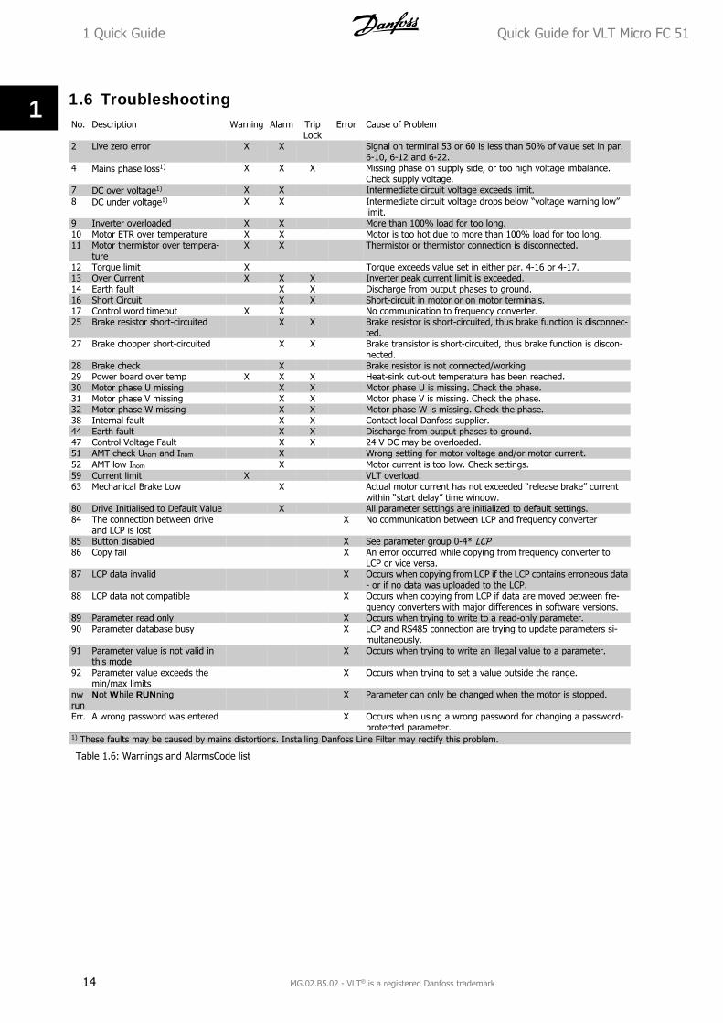
1.6 TroubleshootingNo. Description Warning Alarm Trip
LockError Cause of Problem
2 Live zero error X X Signal on terminal 53 or 60 is less than 50% of value set in par.6-10, 6-12 and 6-22.
4 Mains phase loss1) X X X Missing phase on supply side, or too high voltage imbalance.Check supply voltage.
7 DC over voltage1) X X Intermediate circuit voltage exceeds limit.8 DC under voltage1) X X Intermediate circuit voltage drops below “voltage warning low”
limit.9 Inverter overloaded X X More than 100% load for too long.10 Motor ETR over temperature X X Motor is too hot due to more than 100% load for too long.11 Motor thermistor over tempera-
tureX X Thermistor or thermistor connection is disconnected.
12 Torque limit X Torque exceeds value set in either par. 4-16 or 4-17.13 Over Current X X X Inverter peak current limit is exceeded.14 Earth fault X X Discharge from output phases to ground.16 Short Circuit X X Short-circuit in motor or on motor terminals.17 Control word timeout X X No communication to frequency converter.25 Brake resistor short-circuited X X Brake resistor is short-circuited, thus brake function is disconnec-
ted.27 Brake chopper short-circuited X X Brake transistor is short-circuited, thus brake function is discon-
nected.28 Brake check X Brake resistor is not connected/working29 Power board over temp X X X Heat-sink cut-out temperature has been reached.30 Motor phase U missing X X Motor phase U is missing. Check the phase.31 Motor phase V missing X X Motor phase V is missing. Check the phase.32 Motor phase W missing X X Motor phase W is missing. Check the phase.38 Internal fault X X Contact local Danfoss supplier.44 Earth fault X X Discharge from output phases to ground.47 Control Voltage Fault X X 24 V DC may be overloaded.51 AMT check Unom and Inom X Wrong setting for motor voltage and/or motor current.52 AMT low Inom X Motor current is too low. Check settings.59 Current limit X VLT overload.63 Mechanical Brake Low X Actual motor current has not exceeded “release brake” current
within “start delay” time window.80 Drive Initialised to Default Value X All parameter settings are initialized to default settings.84 The connection between drive
and LCP is lost X No communication between LCP and frequency converter
85 Button disabled X See parameter group 0-4* LCP86 Copy fail X An error occurred while copying from frequency converter to
LCP or vice versa.87 LCP data invalid X Occurs when copying from LCP if the LCP contains erroneous data
- or if no data was uploaded to the LCP.88 LCP data not compatible X Occurs when copying from LCP if data are moved between fre-
quency converters with major differences in software versions.89 Parameter read only X Occurs when trying to write to a read-only parameter.90 Parameter database busy X LCP and RS485 connection are trying to update parameters si-
multaneously.91 Parameter value is not valid in
this mode X Occurs when trying to write an illegal value to a parameter.
92 Parameter value exceeds themin/max limits
X Occurs when trying to set a value outside the range.
nwrun
Not While RUNning X Parameter can only be changed when the motor is stopped.
Err. A wrong password was entered X Occurs when using a wrong password for changing a password-protected parameter.
1) These faults may be caused by mains distortions. Installing Danfoss Line Filter may rectify this problem.
Table 1.6: Warnings and AlarmsCode list
1 Quick Guide Quick Guide for VLT Micro FC 51
14 MG.02.B5.02 - VLT® is a registered Danfoss trademark
1
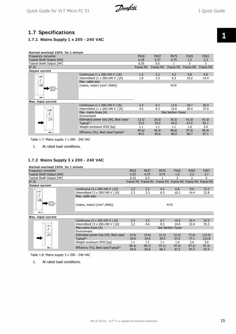
1.7 Specifications1.7.1 Mains Supply 1 x 200 - 240 VAC
Normal overload 150% for 1 minuteFrequency converterTypical Shaft Output [kW]
PK180.18
PK370.37
PK750.75
P1K51.5
P2K22.2
Typical Shaft Output [HP] 0.25 0.5 1 2 3IP 20 Frame M1 Frame M1 Frame M1 Frame M2 Frame M3Output current
Continuous (1 x 200-240 V ) [A] 1.2 2.2 4.2 6.8 9.6Intermittent (1 x 200-240 V ) [A] 1.8 3.3 6.3 10.2 14.4Max. cable size:(mains, motor) [mm2 /AWG] 4/10
Max. input currentContinuous (1 x 200-240 V ) [A] 3.3 6.1 11.6 18.7 26.4Intermittent (1 x 200-240 V ) [A] 4.5 8.3 15.6 26.4 37.0Max. mains fuses [A] See Section FusesEnvironmentEstimated power loss [W], Best case/Typical1)
12.5/15.5
20.0/25.0
36.5/44.0
61.0/67.0
81.0/85.1
Weight enclosure IP20 [kg] 1.1 1.1 1.1 1.6 3.0
Efficiency [%], Best case/Typical1) 95.6/94.5
96.5/95.6
96.6/96.0
97.0/96.7
96.9/97.1
Table 1.7: Mains supply 1 x 200 - 240 VAC
1. At rated load conditions.
1.7.2 Mains Supply 3 x 200 - 240 VAC
Normal overload 150% for 1 minuteFrequency converterTypical Shaft Output [kW]
PK250.25
PK370.37
PK750.75
P1K51.5
P2K22.2
P3K73.7
Typical Shaft Output [HP] 0.33 0.5 1 2 3 5IP 20 Frame M1 Frame M1 Frame M1 Frame M2 Frame M3 Frame M3Output current
Continuous (3 x 200-240 V ) [A] 1.5 2.2 4.2 6.8 9.6 15.2Intermittent (3 x 200-240 V ) [A] 2.3 3.3 6.3 10.2 14.4 22.8Max. cable size:
(mains, motor) [mm2 /AWG] 4/10
Max. input current
Continuous (3 x 200-240 V ) [A] 2.4 3.5 6.7 10.9 15.4 24.3Intermittent (3 x 200-240 V ) [A] 3.2 4.6 8.3 14.4 23.4 35.3Max.mains fuses [A] See Section FusesEnvironment Estimated power loss [W], Best case/Typical1)
14.0/20.0
19.0/24.0
31.5/39.5
51.0/57.0
72.0/77.1
115.0/122.8
Weight enclosure IP20 [kg] 1.1 1.1 1.1 1.6 3.0 3.0
Efficiency [%], Best case/Typical1) 96.4/94.9
96.7/95.8
97.1/96.3
97.4/97.2
97.2/97.4
97.3/97.4
Table 1.8: Mains supply 3 x 200 - 240 VAC
1. At rated load conditions.
Quick Guide for VLT Micro FC 51 1 Quick Guide
MG.02.B5.02 - VLT® is a registered Danfoss trademark 15
1
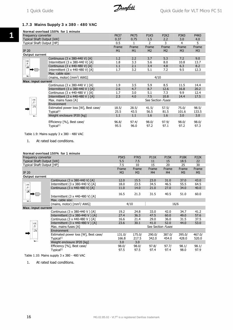
1.7.3 Mains Supply 3 x 380 - 480 VAC
Normal overload 150% for 1 minuteFrequency converterTypical Shaft Output [kW]
PK370.37
PK750.75
P1K51.5
P2K22.2
P3K03.0
P4K04.0
Typical Shaft Output [HP] 0.5 1 2 3 4 5
IP 20 Frame
M1Frame
M1Frame
M2Frame
M2Frame
M3Frame
M3Output current
Continuous (3 x 380-440 V) [A] 1.2 2.2 3.7 5.3 7.2 9.0Intermittent (3 x 380-440 V) [A] 1.8 3.3 5.6 8.0 10.8 13.7Continuous (3 x 440-480 V) [A] 1.1 2.1 3.4 4.8 6.3 8.2Intermittent (3 x 440-480 V) [A] 1.7 3.2 5.1 7.2 9.5 12.3Max. cable size:(mains, motor) [mm2/ AWG] 4/10
Max. input currentContinuous (3 x 380-440 V ) [A] 1.9 3.5 5.9 8.5 11.5 14.4Intermittent (3 x 380-440 V ) [A] 2.6 4.7 8.7 12.6 16.8 20.2Continuous (3 x 440-480 V ) [A] 1.7 3.0 5.1 7.3 9.9 12.4Intermittent (3 x 440-480 V ) [A] 2.3 4.0 7.5 10.8 14.4 17.5Max. mains fuses [A] See Section FusesEnvironmentEstimated power loss [W], Best case/Typical1)
18.5/25.5
28.5/43.5
41.5/56.5
57.5/81.5
75.0/101.6
98.5/133.5
Weight enclosure IP20 [kg] 1.1 1.1 1.6 1.6 3.0 3.0
Efficiency [%], Best case/Typical1)
96.8/95.5
97.4/96.0
98.0/97.2
97.9/97.1
98.0/97.2
98.0/97.3
Table 1.9: Mains supply 3 x 380 - 480 VAC
1. At rated load conditions.
Normal overload 150% for 1 minuteFrequency converterTypical Shaft Output [kW]
P5K55.5
P7K57.5
P11K11
P15K15
P18K18.5
P22K22
Typical Shaft Output [HP] 7.5 10 15 20 25 30
IP 20 Frame
M3Frame
M3Frame
M4Frame
M4Frame
M5Frame
M5Output current
Continuous (3 x 380-440 V) [A] 12.0 15.5 23.0 31.0 37.0 43.0Intermittent (3 x 380-440 V) [A] 18.0 23.5 34.5 46.5 55.5 64.5Continuous (3 x 440-480 V) [A] 11.0 14.0 21.0 27.0 34.0 40.0
Intermittent (3 x 440-480 V) [A]16.5 21.3 31.5 40.5 51.0 60.0
Max. cable size:(mains, motor) [mm2/ AWG] 4/10 16/6
Max. input currentContinuous (3 x 380-440 V ) [A] 19.2 24.8 33.0 42.0 34.7 41.2Intermittent (3 x 380-440 V ) [A] 27.4 36.3 47.5 60.0 49.0 57.6Continuous (3 x 440-480 V ) [A] 16.6 21.4 29.0 36.0 31.5 37.5Intermittent (3 x 440-480 V ) [A] 23.6 30.1 41.0 52.0 44.0 53.0Max. mains fuses [A] See Section FusesEnvironmentEstimated power loss [W], Best case/Typical1)
131.0/166.8
175.0/217.5
290.0/342.0
387.0/454.0
395.0/428.0
467.0/520.0
Weight enclosure IP20 [kg] 3.0 3.0 Efficiency [%], Best case/Typical1)
98.0/97.5
98.0/97.5
97.8/97.4
97.7/97.4
98.1/98.0
98.1/97.9
Table 1.10: Mains supply 3 x 380 - 480 VAC
1. At rated load conditions.
1 Quick Guide Quick Guide for VLT Micro FC 51
16 MG.02.B5.02 - VLT® is a registered Danfoss trademark
1
Protection and Features:
• Electronic thermal motor protection against overload.
• Temperature monitoring of the heatsink ensures that the frequency converter trips in case of overtemperature
• The frequency converter is protected against short-circuits between motor terminals U, V, W.
• If a motor phase is missing, the frequency trips and issues an alarm.
• If a mains phase is missing, the frequency converter trips or issues a warning (depending on the load).
• Monitoring of the intermediate circuit voltage ensures that the frequency converter trips if the intermediatecircuit voltage is too low or too high.
• The frequency converter is protected against earth faults on motor terminals U, V, W.
Mains supply (L1/L, L2, L3/N):Supply voltage 200-240 V ±10%Supply voltage 380-480 V ±10%Supply frequency 50/60 HzMax. imbalance temporary between mains phases 3.0 % of rated supply voltageTrue Power Factor (λ) ≥ 0.4 nominal at rated loadDisplacement Power Factor (cosφ) near unity (> 0.98)Switching on input supply L1/L, L2, L3/N (power-ups) maximum 2 times/min.Environment according to EN60664-1 overvoltage category III/pollution degree 2
The unit is suitable for use on a circuit capable of delivering not more than 100.000 RMS symmetrical Amperes, 240/480V maximum.
Motor output (U, V, W):Output voltage 0 - 100% of supply voltageOutput frequency 0-200 Hz (VVC+), 0-400 Hz (u/f)Switching on output UnlimitedRamp times 0.05 - 3600 sec.
Cable lengths and cross sections:Max. motor cable length, screened/armoured (EMC correct installation) 15 mMax. motor cable length, unscreened/unarmoured 50 mMax. cross section to motor, mains*Connection to load sharing/brake (M1, M2, M3) 6.3 mm insulated Faston PlugsMax. cross section to load sharing/brake (M4, M5) 16 mm2/6AWGMaximum cross section to control terminals, rigid wire 1.5 mm2/16 AWG (2 x 0.75 mm2)Maximum cross section to control terminals, flexible cable 1 mm2/18 AWGMaximum cross section to control terminals, cable with enclosed core 0.5 mm2/20 AWGMinimum cross section to control terminals 0.25 mm2
* See tables for mains supply for more information!
Digital inputs (Pulse/enocder inputs):Programmable digital inputs (Pulse/encoder) 5 (1)Terminal number 18, 19, 27, 29, 33,Logic PNP or NPNVoltage level 0 - 24 V DCVoltage level, logic'0' PNP < 5 V DCVoltage level, logic'1' PNP > 10 V DCVoltage level, logic '0' NPN > 19 V DCVoltage level, logic '1' NPN < 14 V DCMaximum voltage on input 28 V DCInput resistance, Ri approx. 4 kMax. pulse frequency at terminal 33 5000 HzMin. pulse frequency at terminal 33 20 Hz
Analog inputs:Number of analog inputs 2Terminal number 53, 60Voltage mode (Terminal 53) Switch S200=OFF(U)
Quick Guide for VLT Micro FC 51 1 Quick Guide
MG.02.B5.02 - VLT® is a registered Danfoss trademark 17
1

Current mode (Terminal 53 and 60) Switch S200=ON(I)Voltage level 0 -10 VInput resistance, Ri approx. 10 kΩMax. voltage 20 VCurrent level 0/4 to 20 mA (scaleable)Input resistance, Ri approx. 200 ΩMax. current 30 mA
Analog output:Number of programmable analog outputs 1Terminal number 42Current range at analog output 0/4 - 20 mAMax. load to common at analog output 500 ΩMax. voltage at analog output 17 VAccuracy on analog output Max. error: 0.8 % of full scaleResolution on analog output 8 bit
Control card, RS-485 serial communication:Terminal number 68 (P,TX+, RX+), 69 (N,TX-, RX-)Terminal number 61 Common for terminals 68 and 69
Control card, 24 V DC output:Terminal number 12Max. load (M1 and M2) 160 mAMax. load (M3) 30 mAMax. load (M4 and M5) 200 mA
Relay output:Programmable relay output 1Relay 01 Terminal number 01-03 (break), 01-02(make)Max. terminal load (AC-1)1) on 01-02 (NO) (Resistive load) 250 V AC, 2 AMax. terminal load (AC-15)1) on 01-02 (NO) (Inductive load @ cosφ 0.4) 250 V AC, 0.2 AMax. terminal load (DC-1)1) on 01-02 (NO) (Resistive load) 30 V DC, 2 AMax. terminal load (DC-13)1) on 01-02 (NO) (Inductive load) 24 V DC, 0.1AMax. terminal load (AC-1)1) on 01-03 (NC) (Resistive load) 250 V AC, 2 AMax. terminal load (AC-15)1) on 01-03 (NC) (Inductive load @ cosφ 0.4) 250 V AC, 0.2AMax. terminal load (DC-1)1) on 01-03 (NC) (Resistive load) 30 V DC, 2 AMin. terminal load on 01-03 (NC), 01-02 (NO) 24 V DC 10 mA, 24 V AC 20 mAEnvironment according to EN 60664-1 overvoltage category III/pollution degree 2
1) IEC 60947 part 4 and 5
Control card, 10 V DC output:Terminal number 50Output voltage 10.5 V ±0.5 VMax. load 25 mA
All inputs, outputs, circuits, DC supplies and relay contacts are galvanically isolated from the supplyvoltage (PELV) and other high-voltage terminals.
Surroundings:Enclosure IP 20Enclosure kit available IP 21, TYPE 1Vibration test 1.0 gMax. relative humidity 5% - 95%(IEC 60721-3-3; Class 3K3 (non-condensing) during operationAggressive environment (IEC 60721-3-3), coated class 3C3Test method according to IEC 60068-2-43 H2S (10 days)Ambient temperature Max. 40 °C
Derating for high ambient temperature, see section on special conditions
1 Quick Guide Quick Guide for VLT Micro FC 51
18 MG.02.B5.02 - VLT® is a registered Danfoss trademark
1
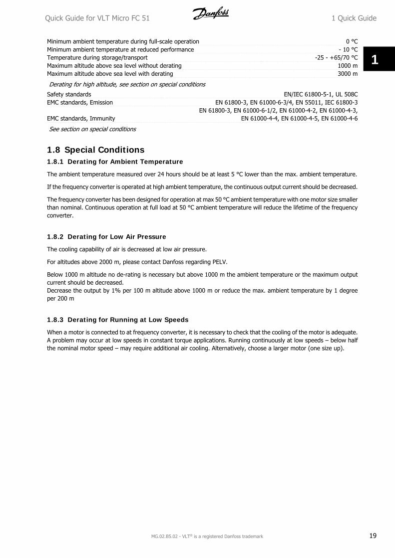
Minimum ambient temperature during full-scale operation 0 °CMinimum ambient temperature at reduced performance - 10 °CTemperature during storage/transport -25 - +65/70 °CMaximum altitude above sea level without derating 1000 mMaximum altitude above sea level with derating 3000 m
Derating for high altitude, see section on special conditions
Safety standards EN/IEC 61800-5-1, UL 508CEMC standards, Emission EN 61800-3, EN 61000-6-3/4, EN 55011, IEC 61800-3
EMC standards, ImmunityEN 61800-3, EN 61000-6-1/2, EN 61000-4-2, EN 61000-4-3,
EN 61000-4-4, EN 61000-4-5, EN 61000-4-6
See section on special conditions
1.8 Special Conditions1.8.1 Derating for Ambient Temperature
The ambient temperature measured over 24 hours should be at least 5 °C lower than the max. ambient temperature.
If the frequency converter is operated at high ambient temperature, the continuous output current should be decreased.
The frequency converter has been designed for operation at max 50 °C ambient temperature with one motor size smallerthan nominal. Continuous operation at full load at 50 °C ambient temperature will reduce the lifetime of the frequencyconverter.
1.8.2 Derating for Low Air Pressure
The cooling capability of air is decreased at low air pressure.
For altitudes above 2000 m, please contact Danfoss regarding PELV.
Below 1000 m altitude no de-rating is necessary but above 1000 m the ambient temperature or the maximum outputcurrent should be decreased.Decrease the output by 1% per 100 m altitude above 1000 m or reduce the max. ambient temperature by 1 degreeper 200 m
1.8.3 Derating for Running at Low Speeds
When a motor is connected to at frequency converter, it is necessary to check that the cooling of the motor is adequate.A problem may occur at low speeds in constant torque applications. Running continuously at low speeds – below halfthe nominal motor speed – may require additional air cooling. Alternatively, choose a larger motor (one size up).
Quick Guide for VLT Micro FC 51 1 Quick Guide
MG.02.B5.02 - VLT® is a registered Danfoss trademark 19
1
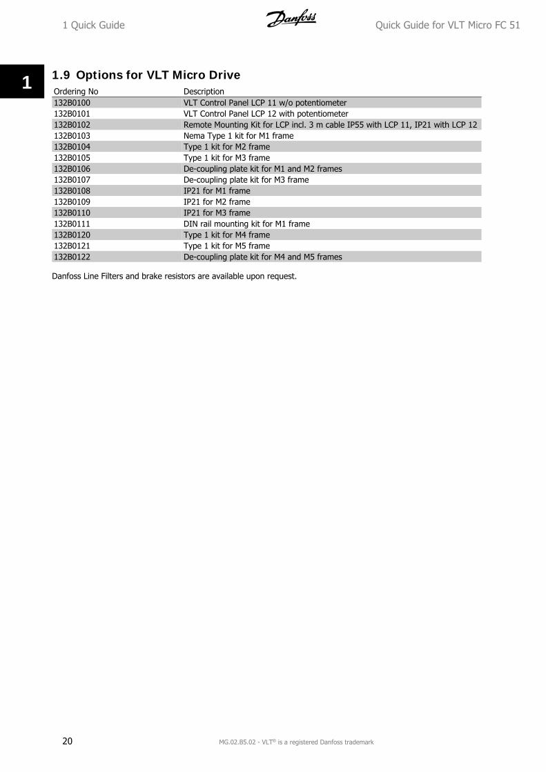
1.9 Options for VLT Micro DriveOrdering No Description132B0100 VLT Control Panel LCP 11 w/o potentiometer132B0101 VLT Control Panel LCP 12 with potentiometer132B0102 Remote Mounting Kit for LCP incl. 3 m cable IP55 with LCP 11, IP21 with LCP 12132B0103 Nema Type 1 kit for M1 frame132B0104 Type 1 kit for M2 frame132B0105 Type 1 kit for M3 frame132B0106 De-coupling plate kit for M1 and M2 frames132B0107 De-coupling plate kit for M3 frame132B0108 IP21 for M1 frame132B0109 IP21 for M2 frame132B0110 IP21 for M3 frame132B0111 DIN rail mounting kit for M1 frame132B0120 Type 1 kit for M4 frame132B0121 Type 1 kit for M5 frame132B0122 De-coupling plate kit for M4 and M5 frames
Danfoss Line Filters and brake resistors are available upon request.
1 Quick Guide Quick Guide for VLT Micro FC 51
20 MG.02.B5.02 - VLT® is a registered Danfoss trademark
1
Top Related