


Languages
Pages
Legal

�
�
All copyright reserved-Hawke Cable Glands Ltd 2002.This document and all copyright therein is the property of Hawke International a trading name of HawkeCable Glands Ltd (A member of the Hubbell Group of Companies). CopyrightCondition:This document shall be used only for the purpose for which it is providedand no reproduction or publication of the document may be made and no articlemay be manufactured or assembled in accordance with information contained inthe document without prior written consent of the owner.
To the best of our knowledge the information contained in this brochure, is accurateat the time of going to print and the company reserves the right to improve ormodify any product illustrated without notification.The company is unable toaccept liability for any inaccuracies, errors or omissions that may exist. It is the customer’s responsibility to ensure that the product is suitable for their application.
HWK12 June ‘02
Visit us at www.ehawke.com
Agent/Distributor
HA
WK
E IN
TE
RN
AT
ION
AL
CA
BL
E G
LA
ND
SF
OR
WO
RL
DW
IDE
AP
PL
ICA
TIO
NS
HW
K12 June ‘02

1Smarter productswww.ehawke.com
Intr
oduc
tion
Introduction
For those who demand quality, reliability and above all, safety, Hawke products are the obvious choice.
Smarter ProductsHawke International is a member of the worldwide Hubbell Group of Companies and is a well established leading manufacturer of electrical equipment for Hazardous (Classified) locations and hostile environments,with an innovative range of cable connection, termination and barrierproducts.
Sustained safety and reliability under extreme conditions are Hawke'sprimary goals. The company also promise ease of installation and low lifetime cost of ownership - due to superior design, long life materials and precision manufacturing.
WorldwideLocated in Manchester, UK, Hawke International has subsidiary companies in Houston, USA and Singapore, along with direct representation in Brazil, the Middle East and Canada. Hawke International is supported worldwide by the Hubbell Group as well as by a network of agents and distributors.
Product DevelopmentA commitment to the development of innovative features which improvethe safety, versatility, reliability and ease of use of our products.
First ChoiceUsed on Offshore and Onshore oil and gas exploration and production facilities. Hawke's products are the 'First Choice' for the world's major oil and gas companies.
A Quality CompanyHawke International's products are designed and manufactured under a quality system not only complying with ISO 9001 but also with the latest international standards. Rigorous and regular in-house testing ensures that every product manufactured meets the highest quality standards.
Hawke International"Leading the way in the design of Smarter Products"
A QUALITY COMPANY ALWAYS DEMANDS THE BEST
HWK21 Feb '04International
AUSMARINE

InternationalHWK21 Feb '04
Flameproof/Increased Safety and Industrial
2Smarter productswww.ehawke.com
Haw
ke C
able
Gla
nds
Con
tent
s
Hawke Cable Glands Contents
Cable Gland Selection Chart 4 - 7
Hazardous Area Cable Glands 9 - 23
Page No.
Cable Gland Features 10501/421 Technical Data 11501/423 Technical Data 12501/453/Universal Technical Data 13501/453/RAC Technical Data 14501/453/RAC/L Technical Data PSG 553/RAC Technical Data ICG 623 Technical Data 17ICG 653/Universal Technical Data 18ICG 653/Universal/L Technical Data 19501/414 Technical Data 20SB 474 Technical Data 21CSB 656 Technical Data 22Oversize Cable Glands 23
Cable Gland Features 26121 Technical Data 27 123 Technical Data 28150/RAC Technical Data 151/RAC Technical Data 30153/RAC Technical Data 31153/RAC/L Technical Data 32114 Technical Data
Industrial Cable Glands 25 - 34
Increased Safety Cable Glands 24
33
29
1516
InternationalHWK21 Feb '04
Flameproof/Increased Safety and Industrial
3Smarter productswww.ehawke.com
Haw
ke C
able
Gla
nds
Con
tent
s
Hawke Cable Glands Contents
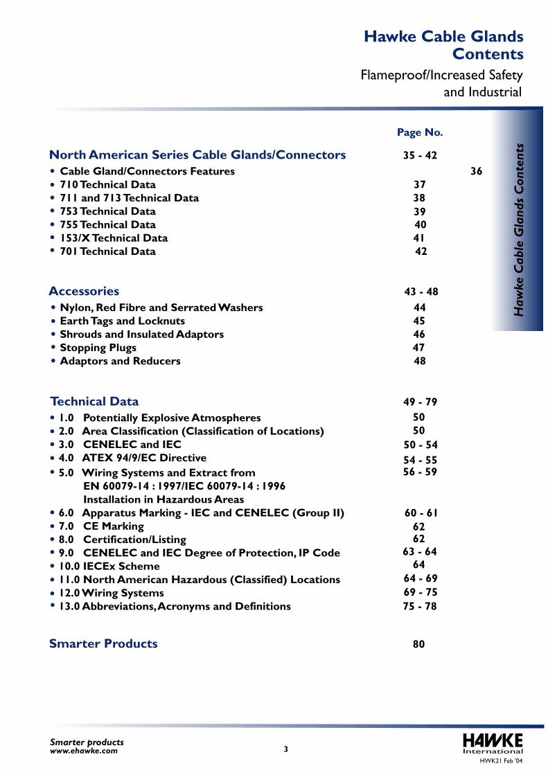
North American Series Cable Glands/Connectors 35 - 42
Page No.
Cable Gland/Connectors Features 36710 Technical Data 37711 and 713 Technical Data 38753 Technical Data 755 Technical Data 40153/X Technical Data 41701 Technical Data 42
Nylon, Red Fibre and Serrated Washers 44Earth Tags and Locknuts 45 Shrouds and Insulated Adaptors 46Stopping Plugs 47Adaptors and Reducers 48
Accessories 43 - 48
Technical Data 49 - 79
1.0 Potentially Explosive Atmospheres2.0 Area Classification (Classification of Locations)3.0 CENELEC and IEC4.0 ATEX 94/9/EC Directive
5050
50 - 54
5.0 Wiring Systems and Extract from EN 60079-14 : 1997/IEC 60079-14 : 1996 Installation in Hazardous Areas6.0 Apparatus Marking - IEC and CENELEC (Group II)7.0 CE Marking8.0 Certification/Listing9.0 CENELEC and IEC Degree of Protection, IP Code10.0 IECEx Scheme11.0 North American Hazardous (Classified) Locations12.0 Wiring Systems13.0 Abbreviations, Acronyms and Definitions 75 - 78
54 - 5556 - 59
Smarter Products 80
60 - 61
63 - 64
62 62
6464 - 6969 - 75
39
PSG 553/RAC
501/453/Universal
501/453/RAC/L
501/453/RAC
501/423
501/421
ICG 653/Universal
ICG 623
Inte
rnatio
nal
4Sm
arter productsw
ww
.ehawke.com
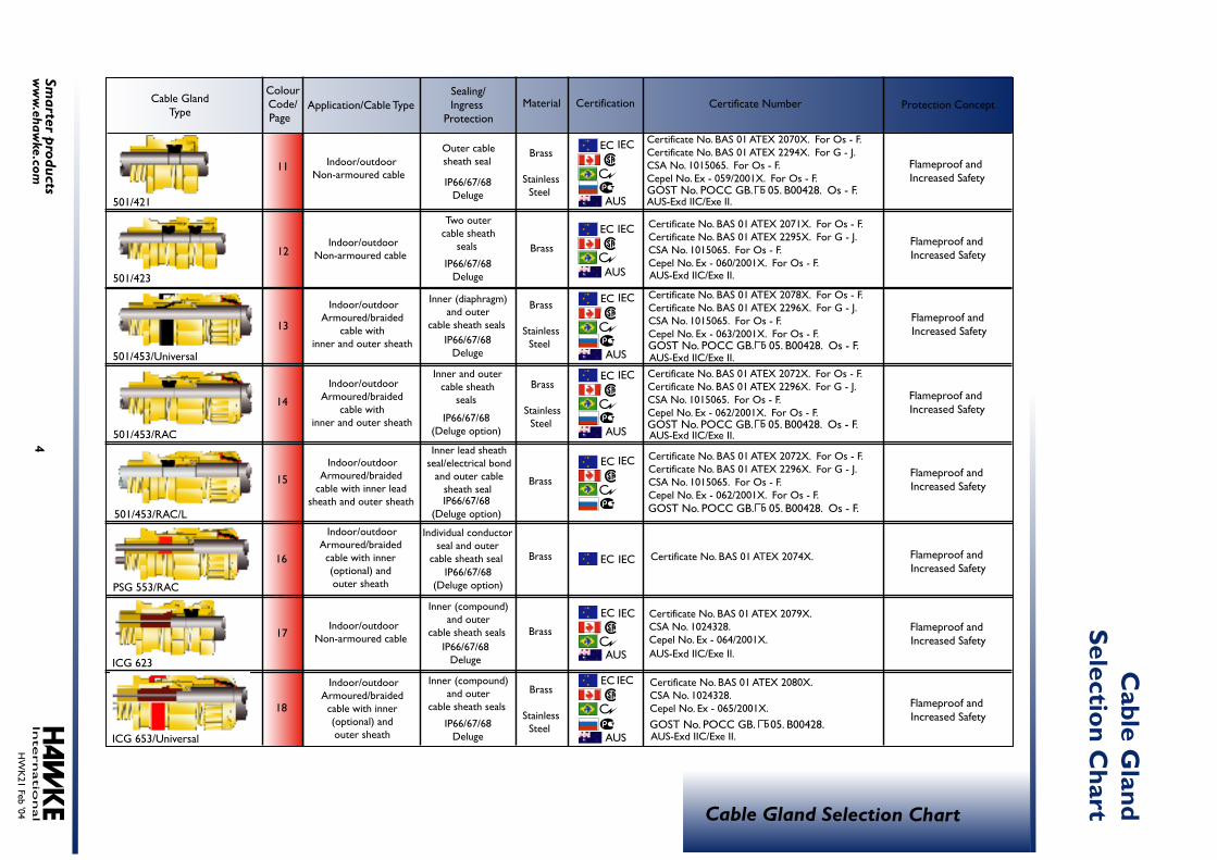
Cable GlandType
ColourCode/Page
Material
Sealing/Ingress
Protection
Application/Cable Type
Certification
Cable Gland Selection Chart
C
able Gland
Selection Chart
Certificate Number
Protection Concept
EC
EC IEC
IEC
EC IEC
EC IEC
EC IEC
EC IEC
EC IEC
EC IEC
Certificate No. BAS 01 ATEX 2070X. For Os - F.Certificate No. BAS 01 ATEX 2294X. For G - J.CSA No. 1015065. For Os - F.Cepel No. Ex - 059/2001X. For Os - F.
Certificate No. BAS 01 ATEX 2071X. For Os - F.Certificate No. BAS 01 ATEX 2295X. For G - J.CSA No. 1015065. For Os - F.Cepel No. Ex - 060/2001X. For Os - F.
Certificate No. BAS 01 ATEX 2078X. For Os - F.Certificate No. BAS 01 ATEX 2296X. For G - J.CSA No. 1015065. For Os - F.Cepel No. Ex - 063/2001X. For Os - F.
Certificate No. BAS 01 ATEX 2072X. For Os - F.Certificate No. BAS 01 ATEX 2296X. For G - J.CSA No. 1015065. For Os - F.Cepel No. Ex - 062/2001X. For Os - F.
Certificate No. BAS 01 ATEX 2072X. For Os - F.Certificate No. BAS 01 ATEX 2296X. For G - J.CSA No. 1015065. For Os - F.Cepel No. Ex - 062/2001X. For Os - F.
Certificate No. BAS 01 ATEX 2080X. CSA No. 1024328. Cepel No. Ex - 065/2001X.
Certificate No. BAS 01 ATEX 2079X. CSA No. 1024328. Cepel No. Ex - 064/2001X.
Certificate No. BAS 01 ATEX 2074X.
HW
K21 Feb '04
Indoor/outdoorArmoured/braided cable with inner (optional) and outer sheath
Indoor/outdoorArmoured/braided
cable with inner lead sheath and outer sheath
Indoor/outdoorNon-armoured cable
Brass
StainlessSteel
Brass
StainlessSteel
Brass
StainlessSteel
Brass
StainlessSteel
Indoor/outdoorNon-armoured cable
Indoor/outdoorNon-armoured cable
Indoor/outdoorArmoured/braided
cable with inner and outer sheath
Indoor/outdoorArmoured/braided
cable with inner and outer sheath
Indoor/outdoorArmoured/braided cable with inner (optional) and outer sheath
IP66/67/68Deluge
IP66/67/68(Deluge option)
IP66/67/68(Deluge option)
IP66/67/68(Deluge option)
IP66/67/68Deluge
IP66/67/68Deluge
IP66/67/68Deluge
IP66/67/68Deluge
Outer cable sheath seal
Two outer cable sheath
seals
Inner and outer cable sheath
seals
Inner lead sheath seal/electrical bond
and outer cable sheath seal
Inner (diaphragm) and outer
cable sheath seals
Inner (compound) and outer
cable sheath seals
Individual conductor seal and outer
cable sheath seal
Inner (compound) and outer
cable sheath seals
Brass
Brass
Brass
Brass
bGOST No. POCC GB. 05. B00428. Os - F.
bGOST No. POCC GB. 05. B00428. Os - F.
bGOST No. POCC GB. 05. B00428. Os - F.
bGOST No. POCC GB. 05. B00428. Os - F.
bGOST No. POCC GB. 05. B00428.
11
12
13
14
15
16
17
18
Flameproof and Increased Safety
Flameproof and Increased Safety
Flameproof and Increased Safety
Flameproof and Increased Safety
Flameproof and Increased Safety
Flameproof and Increased Safety
Flameproof and Increased Safety
Flameproof and Increased Safety
AUS-Exd IIC/Exe II.
AUS-Exd IIC/Exe II.
AUS-Exd IIC/Exe II.
AUS-Exd IIC/Exe II.
AUS-Exd IIC/Exe II.
AUS-Exd IIC/Exe II.
AUS
AUS
AUS
AUS
AUS
AUS

Indoor/outdoorArmoured/braided
cable with inner lead sheath and outer sheath
Indoor/outdoorNon-armoured cable,
conduit system
Indoor/outdoorNon-armoured cable
Indoor/outdoorNon-armoured cable
IP66/67/68Deluge
IP66/67/68Deluge
IP66/67/68Deluge
IP66/67/68Deluge
Outer cable sheath seal
Inner lead sheath seal/electrical bond
and outer cable sheath seal
Outer cable sheath seal
Two outer cable sheath seals
123
Inte
rnatio
nal
5Sm
arter productsw
ww
.ehawke.com
Cable GlandType
ColourCode/Page
Material
Sealing/Ingress
Protection
Application/Cable Type
Certification
Cable Gland Selection Chart
C
able Gland
Selection Chart
Certificate Number
Protection Concept
19
20
21
22
23
24
27
28
501/414
Increased Safety Cable Glands
Oversize G, H & J
CSB 656
IP66/67/68Deluge
IP66/67/68Deluge
Individual conductor seal
Individual conductor(compound) seal
Indoor/outdoorIndividual conductors,
conduit system
Indoor/outdoorIndividual conductors,
conduit system
SB 474
121
PLEASE REFER TO INDIVIDUAL DATA SHEETS FOR DETAILS
PLEASE REFER TO INDIVIDUAL DATA SHEETS FOR DETAILS
ICG 653/UNIV/L
Brass
Brass
Brass
Brass
Brass
Brass
Certificate No. BAS 01 ATEX 2080X. CSA No. 1024328. Cepel No. Ex - 065/2001X.
Certificate No. BAS 01 ATEX 2076X. CSA No. 1015065.
Certificate No. BAS 01 ATEX 2077X.
Certificate No. BAS 01 ATEX 2082X. CSA No. 1024328.
bGOST No. POCC GB. 05. B00428.
HW
K21 Feb '04
Flameproof and Increased Safety
Flameproof and Increased Safety
Flameproof and Increased Safety
Flameproof and Increased Safety
Industrial
Industrial
EC IEC
EC IEC
EC IEC
EC IEC
AUS-Exd IIC/Exe II.AUS

Inte
rnatio
nal
6Sm
arter productsw
ww
.ehawke.com
Cable GlandType
ColourCode/Page
Material
Sealing/Ingress
Protection
Application/Cable Type
Certification
Cable Gland Selection Chart
C
able Gland
Selection Chart
Certificate Number
Protection Concept
HW
K21 Feb '04
Brass
IP66/67/68(Deluge option)
Inner lead sheath seal/electrical bond
and outer cable sheath seal
Brass
Brass
Brass
Brass
Brasswith
NickelPlatedEntry
Brasswith
NickelPlatedEntry
Brass withNickelPlated
Entry andStainless
Steel
29
30
31
32
33
37
38
39
Industrial
Industrial
Industrial
Industrial
Industrial
Explosion ProofUL File No. E84940.
UL File No. E84940.
UL File No. E84941.
Explosion Proof
Explosion Proof
Dry Indoor/outdoorArmoured/braided cable with inner (optional) and outer sheath
Indoor/outdoorArmoured/braided cable
with inner (optional) and outer sheath
150/RAC
151/RAC
IP66/67/68Deluge
IP66(Deluge option)
Indoor/outdoorArmoured/braided cable
with inner and outer cable sheath
Outer cable sheath seal
IP66/67(Deluge option)
Inner (diaphragm) and outer
cable sheath seal
Outer cable sheath sealIndoor/outdoor
Non-armoured cable,conduit system
114
710
753
711 and 713
153/RAC
153/RAC/L
Indoor/outdoorArmoured/braided cable with inner lead sheath
and outer sheath
IP66/67/68
Inner (compound) and outer cable
jacket seals
Inner (compound) and outer cable
jacket seals
Inner (compound) and outer cable
jacket seals
Indoor/outdoorNon-armoured
cable
Indoor/outdoorType MCHL and
Teck cables
Indoor/outdoorArmoured MarineShipboard cable
C
C
C
NEMA 4X & Deluge
IP66/67/68 NEMA 4X & Deluge
IP66/67/68 NEMA 4X & Deluge
Inte
rnatio
nal
7Sm
arter productsw
ww
.ehawke.com
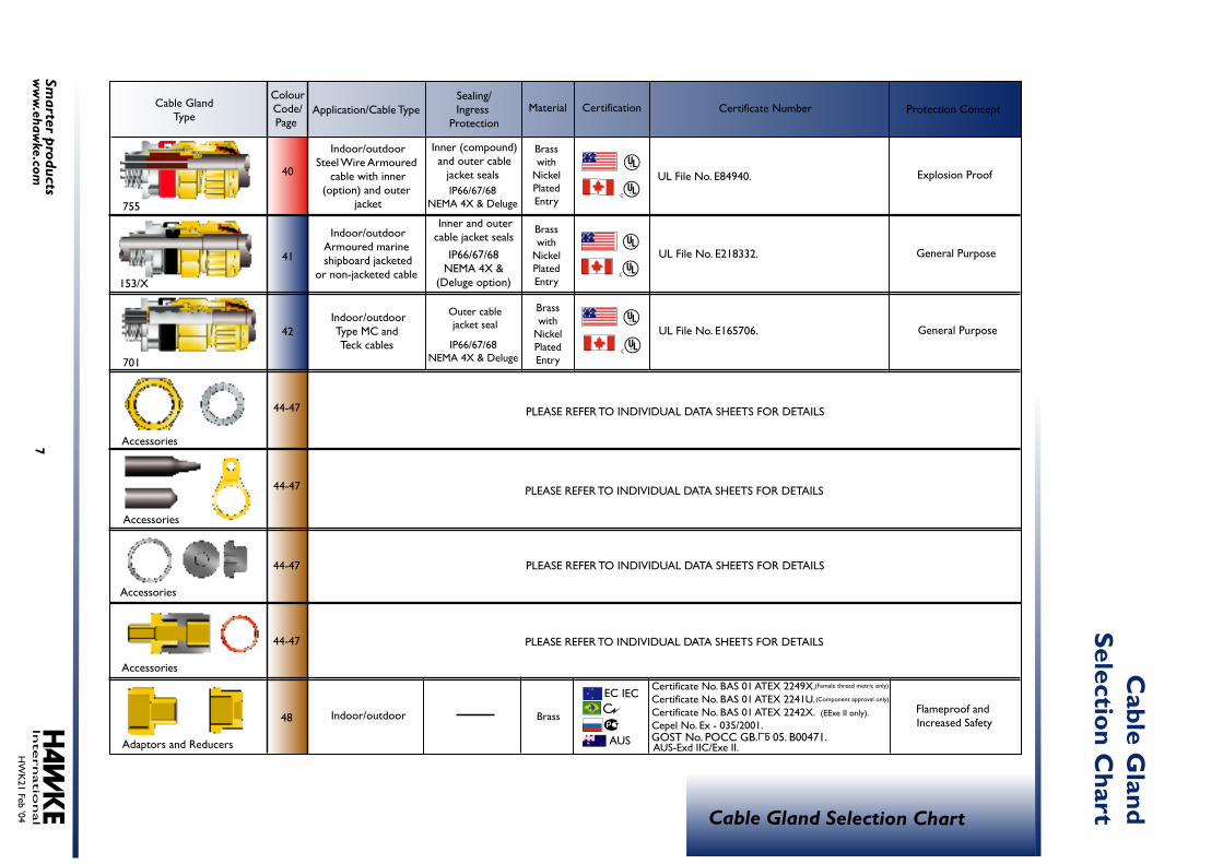
Cable GlandType
ColourCode/Page
Material
Sealing/Ingress
Protection
Application/Cable Type
Certification
Cable Gland Selection Chart
C
able Gland
Selection Chart
Certificate Number
Protection Concept
HW
K21 Feb '04
Brasswith
NickelPlatedEntry
Brasswith
NickelPlatedEntry
Brass
Brasswith
NickelPlatedEntry
40
41
42
44-47
44-47
44-47
44-47
48
General Purpose
General Purpose
Flameproof and Increased Safety
Explosion ProofUL File No. E84940.
UL File No. E218332.
UL File No. E165706.
755
153/X
IP66/67/68NEMA 4X & Deluge
Outer cablejacket seal
701
Accessories
Accessories
Accessories
Accessories
Adaptors and Reducers
IP66/67/68NEMA 4X & Deluge
IP66/67/68NEMA 4X &
(Deluge option)
Inner (compound) and outer cable
jacket seals
Inner and outer cable jacket seals
Indoor/outdoorType MC and Teck cables
Indoor/outdoor
Indoor/outdoorSteel Wire Armoured
cable with inner(option) and outer
jacket
Indoor/outdoorArmoured marine shipboard jacketed
or non-jacketed cable
C
C
C
Certificate No. BAS 01 ATEX 2249X. Certificate No. BAS 01 ATEX 2241U. Certificate No. BAS 01 ATEX 2242X. (EExe II only).Cepel No. Ex - 035/2001.
PLEASE REFER TO INDIVIDUAL DATA SHEETS FOR DETAILS
PLEASE REFER TO INDIVIDUAL DATA SHEETS FOR DETAILS
PLEASE REFER TO INDIVIDUAL DATA SHEETS FOR DETAILS
PLEASE REFER TO INDIVIDUAL DATA SHEETS FOR DETAILS
(Female thread metric only)
(Component approval only)
bGOST No. POCC GB. 05. B00471.
EC IEC
AUS-Exd IIC/Exe II.AUS
InternationalHWK21 Feb '04
Flameproof/Increased Safety and Industrial
8Smarter productswww.ehawke.com
Haw
ke C
able
Gla
nds
Hawke Cable Glands
InternationalHWK21 Feb '04
9Smarter productswww.ehawke.com
Haz
ardo
us A
rea
Cab
le G
land
s
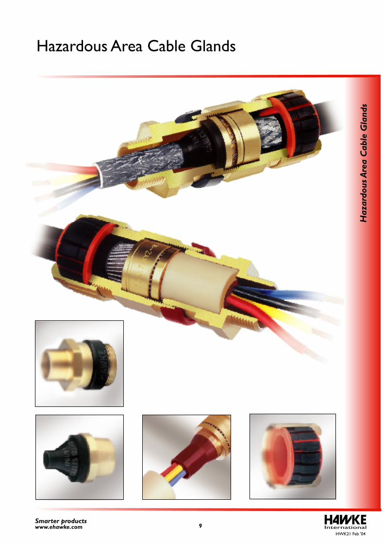
Hazardous Area Cable Glands
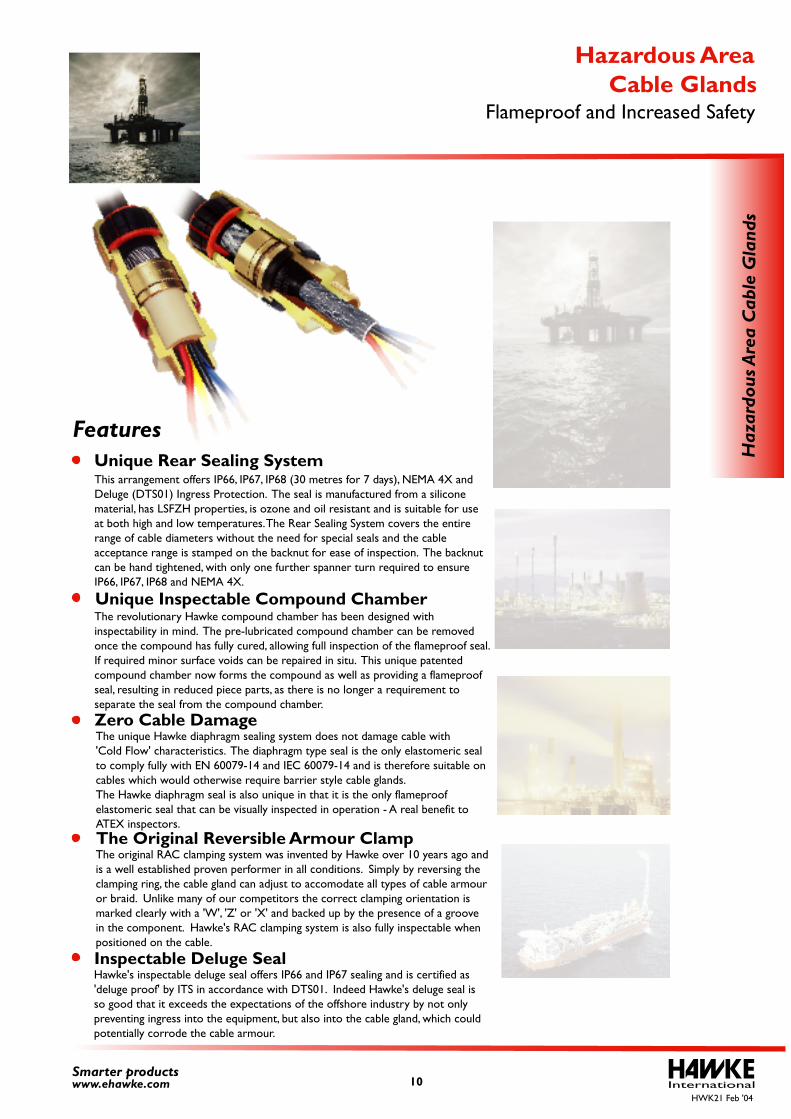
Features
Unique Inspectable Compound Chamber
Zero Cable Damage
Unique Rear Sealing System This arrangement offers IP66, IP67, IP68 (30 metres for 7 days), NEMA 4X and Deluge (DTS01) Ingress Protection. The seal is manufactured from a silicone material, has LSFZH properties, is ozone and oil resistant and is suitable for use at both high and low temperatures. The Rear Sealing System covers the entire range of cable diameters without the need for special seals and the cableacceptance range is stamped on the backnut for ease of inspection. The backnut can be hand tightened, with only one further spanner turn required to ensure IP66, IP67, IP68 and NEMA 4X.
The revolutionary Hawke compound chamber has been designed with inspectability in mind. The pre-lubricated compound chamber can be removedonce the compound has fully cured, allowing full inspection of the flameproof seal.If required minor surface voids can be repaired in situ. This unique patented compound chamber now forms the compound as well as providing a flameproof seal, resulting in reduced piece parts, as there is no longer a requirement to separate the seal from the compound chamber.
The unique Hawke diaphragm sealing system does not damage cable with 'Cold Flow' characteristics. The diaphragm type seal is the only elastomeric seal to comply fully with EN 60079-14 and IEC 60079-14 and is therefore suitable on cables which would otherwise require barrier style cable glands.The Hawke diaphragm seal is also unique in that it is the only flameproof elastomeric seal that can be visually inspected in operation - A real benefit toATEX inspectors.
Inspectable Deluge Seal
The Original Reversible Armour ClampThe original RAC clamping system was invented by Hawke over 10 years ago andis a well established proven performer in all conditions. Simply by reversing theclamping ring, the cable gland can adjust to accomodate all types of cable armouror braid. Unlike many of our competitors the correct clamping orientation ismarked clearly with a 'W', 'Z' or 'X' and backed up by the presence of a groovein the component. Hawke's RAC clamping system is also fully inspectable whenpositioned on the cable.
Hawke's inspectable deluge seal offers IP66 and IP67 sealing and is certified as 'deluge proof' by ITS in accordance with DTS01. Indeed Hawke's deluge seal isso good that it exceeds the expectations of the offshore industry by not only preventing ingress into the equipment, but also into the cable gland, which could potentially corrode the cable armour.
InternationalHWK21 Feb '04
10Smarter productswww.ehawke.com
Haz
ardo
us A
rea
Cab
le G
land
s
Flameproof and Increased Safety Cable Glands
Hazardous Area
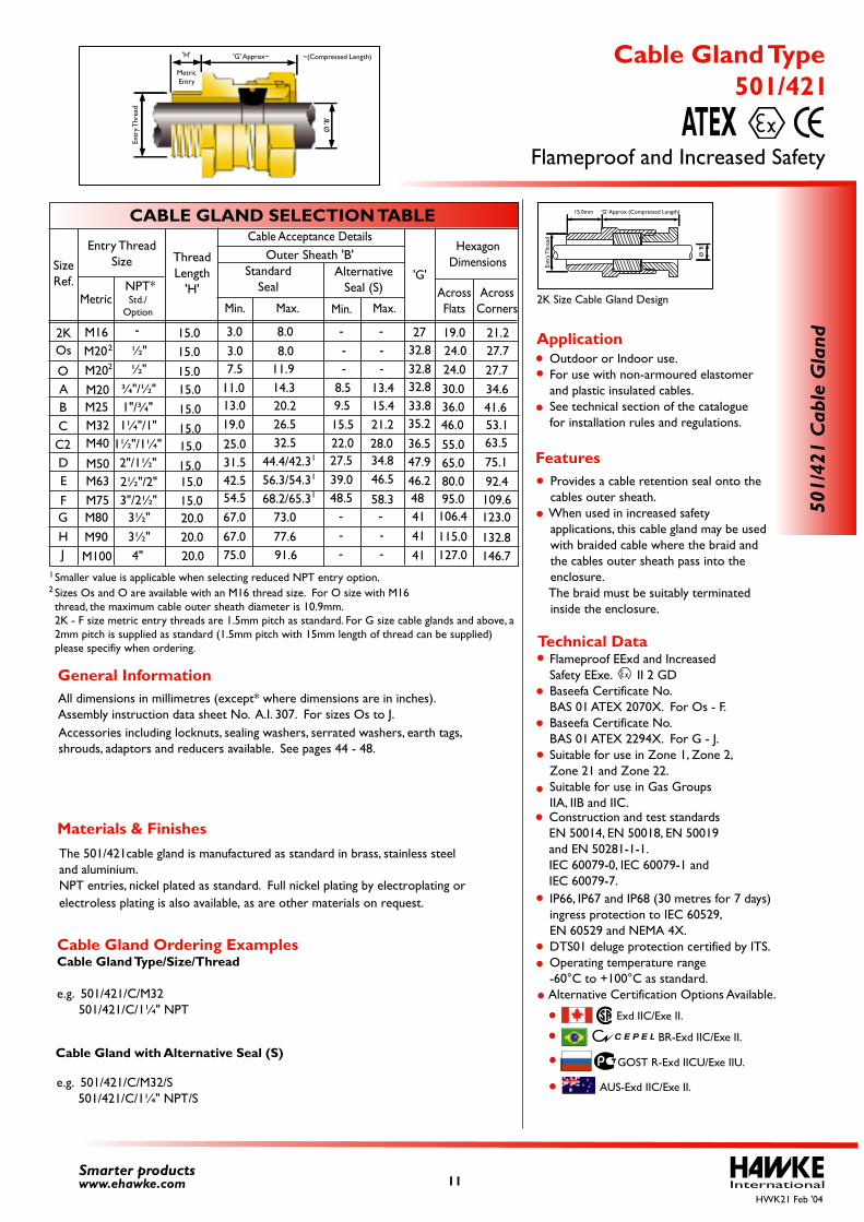
Flameproof EExd and Increased Safety EExe. II 2 GD Baseefa Certificate No. BAS 01 ATEX 2070X. For Os - F. Baseefa Certificate No. BAS 01 ATEX 2294X. For G - J. Suitable for use in Zone 1, Zone 2, Zone 21 and Zone 22. Suitable for use in Gas Groups IIA, IIB and IIC.
IP66, IP67 and IP68 (30 metres for 7 days) ingress protection to IEC 60529, EN 60529 and NEMA 4X. DTS01 deluge protection certified by ITS. Operating temperature range -60°C to +100°C as standard. Alternative Certification Options Available.
Construction and test standards EN 50014, EN 50018, EN 50019 and EN 50281-1-1.IEC 60079-0, IEC 60079-1 and IEC 60079-7.
GOST R-Exd IICU/Exe IIU.
BR-Exd IIC/Exe II.
Exd IIC/Exe II.
The 501/421cable gland is manufactured as standard in brass, stainless steel and aluminium.
All dimensions in millimetres (except* where dimensions are in inches).Assembly instruction data sheet No. A.I. 307. For sizes Os to J.Accessories including locknuts, sealing washers, serrated washers, earth tags, shrouds, adaptors and reducers available. See pages 44 - 48.
Outdoor or Indoor use. For use with non-armoured elastomer and plastic insulated cables. See technical section of the catalogue for installation rules and regulations.
Provides a cable retention seal onto the cables outer sheath. When used in increased safety applications, this cable gland may be used with braided cable where the braid and the cables outer sheath pass into the enclosure. The braid must be suitably terminated inside the enclosure.
Cable Gland Ordering ExamplesCable Gland Type/Size/Thread
e.g. 501/421/C/M32 501/421/C/1¼" NPT
e.g. 501/421/C/M32/S 501/421/C/1¼" NPT/S
Cable Gland with Alternative Seal (S)
AUS-Exd IIC/Exe II.
Smaller value is applicable when selecting reduced NPT entry option. 1
2 Sizes Os and O are available with an M16 thread size. For O size with M16 thread, the maximum cable outer sheath diameter is 10.9mm.2K - F size metric entry threads are 1.5mm pitch as standard. For G size cable glands and above, a 2mm pitch is supplied as standard (1.5mm pitch with 15mm length of thread can be supplied) please specifiy when ordering.
15.015.015.015.015.015.015.015.015.015.020.020.020.0
International11Smarter productswww.ehawke.com
CABLE GLAND SELECTION TABLE
SizeRef.
O
Os
ABCC2DE
F
M20M20M25M32M40
M50M63M75
¾"/½"
M20 ½"
2"/1½"2½"/2"3"/2½"
½"
1"/¾"1¼"/1"
1½"/1¼"
Entry ThreadSize
MetricNPT*
Cable Acceptance Details
Min. Max.Std./
Option
'G'AcrossFlats
AcrossCorners
HexagonDimensions
24.030.036.046.0
55.065.080.095.0
27.734.641.653.163.575.192.4109.6
24.0 27.72K
HJ
M16
M80
M90M100
3½"3½"
4"
3.07.5
11.013.019.025.031.542.554.5
8.011.914.320.226.532.5
44.4/42.356.3/54.368.2/65.3
8.59.515.522.027.539.048.5
13.415.421.228.034.846.5
58.3
32.832.8
27
32.833.835.2
36.547.946.248414141
19.0 21.2
Min. Max.
Outer Sheath 'B'
G
-3.0 8.0-
---
StandardSeal
AlternativeSeal (S)
- -- -
- -
- -
67.067.075.0
73.077.691.6
106.4
115.0127.0
123.0
132.8146.7
1
1
1
2
2
ThreadLength
'H'
501/
421
Cab
le G
land
Flameproof and Increased Safety
501/421 Cable Gland Type
ATEX
Technical Data
General Information
Features
Application
Materials & Finishes
'G' Approx (Compressed Length)15.0mm
Ø 'B
'
Entr
y Thr
ead
HWK21 Feb '04
2K Size Cable Gland Design
'G' Approx~'H'
MetricEntry
Ø 'B
'
Entr
y Thr
ead
~(Compressed Length)
electroless plating is also available, as are other materials on request.NPT entries, nickel plated as standard. Full nickel plating by electroplating or
Flameproof EExd and Increased Safety EExe. II 2 GD Baseefa Certificate No. BAS 01 ATEX 2071X. For Os - F. Baseefa Certificate No. BAS 01 ATEX 2295X. For G - J. Suitable for use in Zone 1, Zone 2, Zone 21 and Zone 22. Suitable for use in Gas Groups IIA, IIB and IIC.
IP66, IP67 and IP68 (30 metres for 7 days) ingress protection to IEC 60529, EN 60529 and NEMA 4X. DTS01 deluge protection certified by ITS. Additional deluge protection seal also available. Operating temperature range -60°C to +100°C as standard. Alternative Certification Options Available.
Construction and test standards EN 50014, EN 50018, EN 50019 and EN 50281-1-1.IEC 60079-0, IEC 60079-1 and IEC 60079-7.
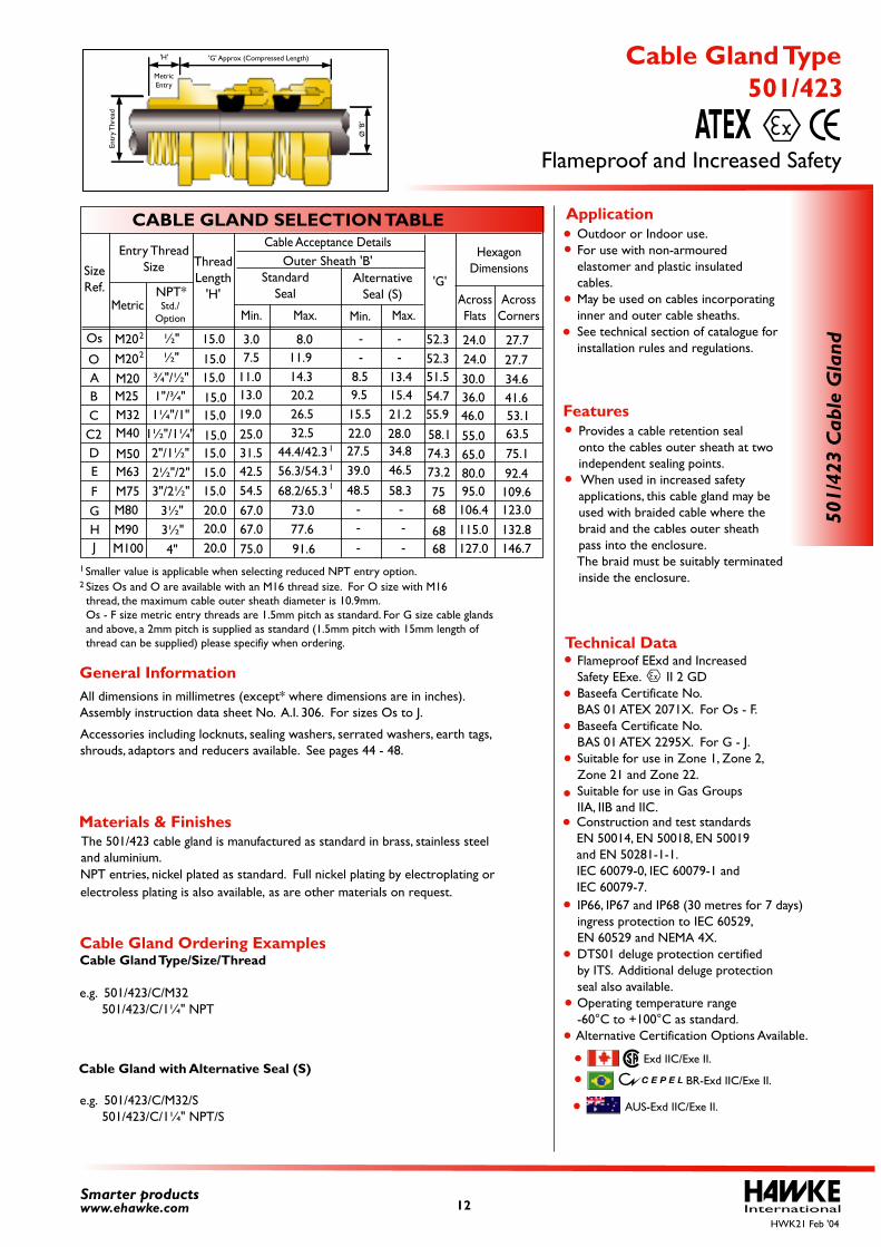
The 501/423 cable gland is manufactured as standard in brass, stainless steeland aluminium.
Outdoor or Indoor use. For use with non-armoured elastomer and plastic insulated cables. May be used on cables incorporating inner and outer cable sheaths. See technical section of catalogue for installation rules and regulations.
Provides a cable retention seal onto the cables outer sheath at two independent sealing points. When used in increased safety applications, this cable gland may be used with braided cable where the braid and the cables outer sheath pass into the enclosure. The braid must be suitably terminated inside the enclosure.
Cable Gland Ordering ExamplesCable Gland Type/Size/Thread e.g. 501/423/C/M32 501/423/C/1¼" NPT
Cable Gland with Alternative Seal (S)
e.g. 501/423/C/M32/S 501/423/C/1¼" NPT/S
All dimensions in millimetres (except* where dimensions are in inches).Assembly instruction data sheet No. A.I. 306. For sizes Os to J.
Accessories including locknuts, sealing washers, serrated washers, earth tags, shrouds, adaptors and reducers available. See pages 44 - 48.
Smaller value is applicable when selecting reduced NPT entry option. 1
2
AUS-Exd IIC/Exe II.
Sizes Os and O are available with an M16 thread size. For O size with M16 thread, the maximum cable outer sheath diameter is 10.9mm.Os - F size metric entry threads are 1.5mm pitch as standard. For G size cable glands and above, a 2mm pitch is supplied as standard (1.5mm pitch with 15mm length of thread can be supplied) please specifiy when ordering.
International12Smarter productswww.ehawke.com
CABLE GLAND SELECTION TABLE
SizeRef.
O
Os
ABCC2DE
F
M20M20M25M32M40
M50M63M75
¾"/½"
M20 ½"
2"/1½"2½"/2"3"/2½"
½"
1"/¾"1¼"/1"
1½"/1¼"
Entry ThreadSize
MetricNPT*Std./
Option
H J
M80M90M100
3½"3½"
4"
106.4115.0127.0
123.0132.8146.7
G
3.07.5
11.013.019.025.031.542.554.5
8.011.914.320.226.532.5
44.4/42.356.3/54.368.2/65.3
8.59.515.522.027.539.048.5
13.415.421.228.034.846.5
58.3
--
-- 24.0
30.036.046.0
55.065.080.095.0
27.734.641.653.163.575.192.4109.6
24.0 27.752.352.351.554.755.9
73.2
58.174.3
7568
6868
Min. Max.
'G'AcrossFlats
AcrossCorners
HexagonDimensions
Min. Max.
Outer Sheath 'B'Standard
SealAlternative
Seal (S)
67.067.075.0
73.077.691.6
- -
- -- -
1
1
1
2
2
ThreadLength
'H'
15.015.015.015.015.015.015.015.015.020.020.020.0
501/
423
Cab
le G
land
Cable Acceptance Details
Flameproof and Increased Safety
501/423 Cable Gland Type
ATEX
Technical Data
Features
Application
Materials & Finishes
General Information
HWK21 Feb '04
'H' 'G' Approx (Compressed Length)
Ø 'B
'
Entr
y Thr
ead
MetricEntry
BR-Exd IIC/Exe II.
Exd IIC/Exe II.
electroless plating is also available, as are other materials on request.NPT entries, nickel plated as standard. Full nickel plating by electroplating or
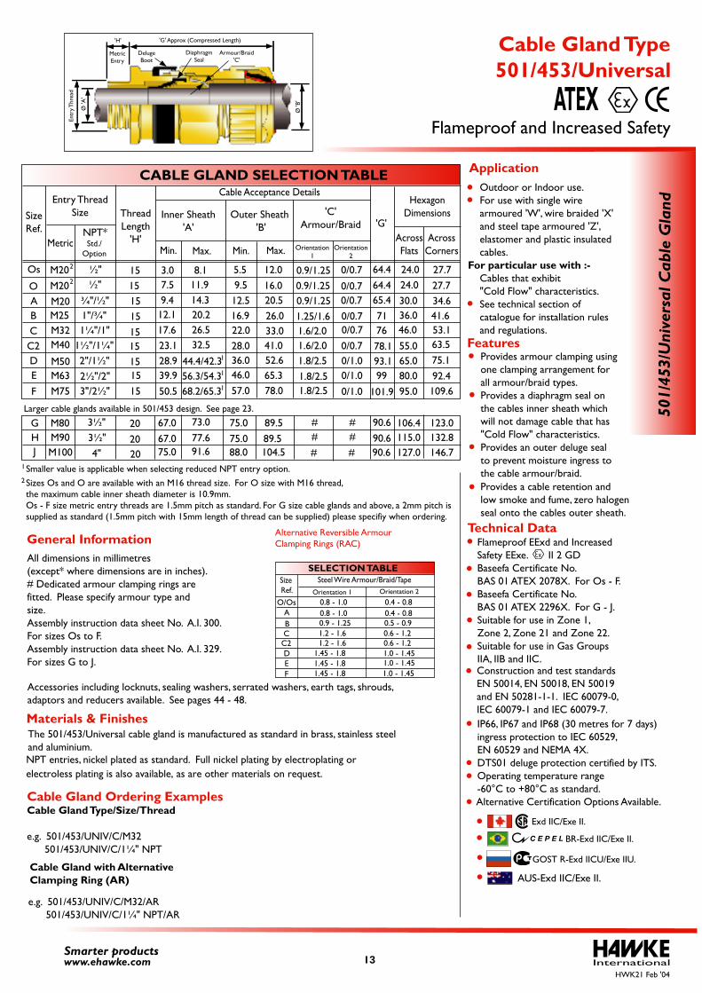
Larger cable glands available in 501/453 design. See page 23.
Flameproof EExd and Increased Safety EExe. II 2 GD Baseefa Certificate No. BAS 01 ATEX 2078X. For Os - F. Baseefa Certificate No. BAS 01 ATEX 2296X. For G - J. Suitable for use in Zone 1, Zone 2, Zone 21 and Zone 22. Suitable for use in Gas Groups IIA, IIB and IIC.
IP66, IP67 and IP68 (30 metres for 7 days) ingress protection to IEC 60529, EN 60529 and NEMA 4X. DTS01 deluge protection certified by ITS. Operating temperature range -60°C to +80°C as standard. Alternative Certification Options Available.
Construction and test standards EN 50014, EN 50018, EN 50019 and EN 50281-1-1. IEC 60079-0, IEC 60079-1 and IEC 60079-7.
GOST R-Exd IICU/Exe IIU.
BR-Exd IIC/Exe II.
Exd IIC/Exe II.
The 501/453/Universal cable gland is manufactured as standard in brass, stainless steeland aluminium.
All dimensions in millimetres (except* where dimensions are in inches).# Dedicated armour clamping rings are fitted. Please specify armour type and size.Assembly instruction data sheet No. A.I. 300. For sizes Os to F.Assembly instruction data sheet No. A.I. 329. For sizes G to J.
Accessories including locknuts, sealing washers, serrated washers, earth tags, shrouds, adaptors and reducers available. See pages 44 - 48.
0.8 - 1.0 0.4 - 0.80.8 - 1.0 0.4 - 0.80.9 - 1.25 0.5 - 0.91.2 - 1.6 0.6 - 1.21.2 - 1.6 0.6 - 1.2
1.45 - 1.8 1.0 - 1.45 1.0 - 1.45 1.0 - 1.45
1.45 - 1.8 1.45 - 1.8
SELECTION TABLE
AO/Os
BC
DEF
C2
Size Ref.
Steel Wire Armour/Braid/TapeOrientation 1 Orientation 2
Alternative Reversible Armour Clamping Rings (RAC)
Outdoor or Indoor use. For use with single wire armoured 'W', wire braided 'X' and steel tape armoured 'Z', elastomer and plastic insulated cables.For particular use with :- Cables that exhibit "Cold Flow" characteristics.
See technical section of catalogue for installation rules and regulations.
Provides armour clamping using one clamping arrangement for all armour/braid types. Provides a diaphragm seal on the cables inner sheath which will not damage cable that has "Cold Flow" characteristics. Provides an outer deluge seal to prevent moisture ingress to the cable armour/braid.
Provides a cable retention and low smoke and fume, zero halogen seal onto the cables outer sheath.
Cable Gland Ordering ExamplesCable Gland Type/Size/Thread
e.g. 501/453/UNIV/C/M32 501/453/UNIV/C/1¼" NPT
Cable Gland with Alternative Clamping Ring (AR)
e.g. 501/453/UNIV/C/M32/AR 501/453/UNIV/C/1¼" NPT/AR
AUS-Exd IIC/Exe II.
2 Sizes Os and O are available with an M16 thread size. For O size with M16 thread, the maximum cable inner sheath diameter is 10.9mm.Os - F size metric entry threads are 1.5mm pitch as standard. For G size cable glands and above, a 2mm pitch is supplied as standard (1.5mm pitch with 15mm length of thread can be supplied) please specifiy when ordering.
Smaller value is applicable when selecting reduced NPT entry option. 1
InternationalSmarter productswww.ehawke.com
CABLE GLAND SELECTION TABLE
SizeRef.
O
Os
ABCC2DE
F
M20M20M25M32M40
M50M63M75
¾"/½"
M20 ½"
2"/1½"2½"/2"3"/2½"
½"
1"/¾"1¼"/1"
1½"/1¼"
Entry ThreadSize
MetricNPT*
Outer Sheath 'B'
Cable Acceptance Details
Min. Max.Max.Std./
OptionOrientation
2Orientation
1
'G'AcrossFlats
AcrossCorners
HexagonDimensions'C'
Armour/Braid
24.030.036.046.0
55.065.080.095.0
27.734.641.653.163.575.192.4109.6
24.0 27.764.464.465.4717678.193.199
90.690.690.6
101.9
9.512.516.922.028.036.046.057.0
16.05.5
Min.
12.0
20.526.033.041.052.665.378.0
0.9/1.250.9/1.251.25/1.61.6/2.01.6/2.01.8/2.51.8/2.51.8/2.5
0/0.70.9/1.25 0/0.7
0/0.7 0/0.70/0.70/0.70/1.00/1.00/1.0
H J
M80M90M100
3½"3½"
4"
106.4115.0127.0
123.0132.8146.7
G ###
###
Inner Sheath'A'
3.07.5
9.412.117.623.128.939.950.5
11.914.320.226.532.5
44.4/42.3
8.1
56.3/54.368.2/65.3
67.067.075.0
73.077.691.6
89.589.5104.5
75.075.088.0
1
1
1
2
2
ThreadLength
'H'
501/
453/
Uni
vers
al C
able
Gla
nd
151515151515151515
202020
Flameproof and Increased Safety
501/453/Universal Cable Gland Type
ATEX
Technical DataGeneral Information
Features
Application
Materials & Finishes
HWK21 Feb '04
Ø 'A
'
Entr
y Thr
ead
'G' Approx (Compressed Length)'H'
MetricEntry
DelugeBoot
DiaphragmSeal
Armour/Braid'C'
Ø 'B
'
13
electroless plating is also available, as are other materials on request.NPT entries, nickel plated as standard. Full nickel plating by electroplating or
Flameproof EExd and Increased Safety EExe. II 2 GD Baseefa Certificate No. BAS 01 ATEX 2072X. For Os - F. Baseefa Certificate No. BAS 01 ATEX 2296X. For G - J. Suitable for use in Zone 1, Zone 2, Zone 21 and Zone 22. Suitable for use in Gas Groups IIA, IIB and IIC.
IP66, IP67 and IP68 (30 metres for 7 days) ingress protection to IEC 60529, EN 60529 and NEMA 4X. DTS01 deluge protection certified by ITS. Operating temperature range -60°C to +80°C as standard. Alternative Certification Options Available.
Construction and test standards EN 50014, EN 50018, EN 50019 and EN 50281-1-1.IEC 60079-0, IEC 60079-1 and IEC 60079-7.
GOST R-Exd IICU/Exe IIU.
BR-Exd IIC/Exe II.
Exd IIC/Exe II.
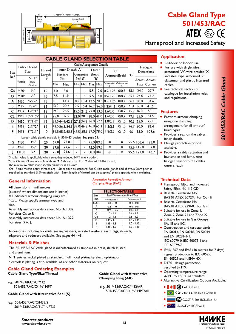
The 501/453/RAC cable gland is manufactured as standard in brass, stainless steeland aluminium.
All dimensions in millimetres (except* where dimensions are in inches).# Dedicated armour clamping rings are fitted. Please specify armour type and size.Assembly instruction data sheet No. A.I. 302. For sizes Os to F.Assembly instruction data sheet No. A.I. 329. For sizes G to J.
Accessories including locknuts, sealing washers, serrated washers, earth tags, shrouds, adaptors and reducers available. See pages 44 - 48.
0.8 - 1.0 0.4 - 0.80.8 - 1.0 0.4 - 0.80.9 - 1.25 0.5 - 0.91.2 - 1.6 0.6 - 1.21.2 - 1.6 0.6 - 1.2
1.45 - 1.8 1.0 - 1.45 1.0 - 1.45 1.0 - 1.45
1.45 - 1.8 1.45 - 1.8
SELECTION TABLE
AO/Os
BC
DEF
C2
Size Ref.
Steel Wire Armour/Braid/TapeOrientation 1 Orientation 2
Alternative Reversible Armour Clamping Rings (RAC)
AlternativeSeal (S)
Min. Max.
-
Outdoor or Indoor use. For use with single wire armoured 'W', wire braided 'X' and steel tape armoured 'Z', elastomer and plastic insulated cables. See technical section of
catalogue for installation rules and regulations.
Provides armour clamping using one clamping arrangement for all armour/ braid types. Provides a seal on the cables inner sheath. Deluge protection option available. Provides a cable retention and
low smoke and fume, zero halogen seal onto the cables outer sheath.
Cable Gland Ordering ExamplesCable Gland Type/Size/Thread
e.g. 501/453/RAC/C/M32 501/453/RAC/C/1¼" NPT
Cable Gland with Alternative Seal (S)
e.g. 501/453/RAC/C/M32/S 501/453/RAC/C/1¼" NPT/S
Cable Gland with Alternative Clamping Ring (AR)
e.g. 501/453/RAC/C/M32/AR 501/453/RAC/C/1¼" NPT/AR
AUS-Exd IIC/Exe II.
2Sizes Os and O are available with an M16 thread size. For O size with M16 thread,the maximum cable inner sheath diameter is 10.9mm.Os - F size metric entry threads are 1.5mm pitch as standard. For G size cable glands and above, a 2mm pitch is supplied as standard (1.5mm pitch with 15mm length of thread can be supplied) please specifiy when ordering.
InternationalSmarter productswww.ehawke.com
CABLE GLAND SELECTION TABLE
SizeRef.
O
Os
ABCC2DE
F
M20M20M25M32M40
M50M63M75
¾"/½"
M20 ½"
2"/1½"2½"/2"3"/2½"
½"
1"/¾"1¼"/1"
1½"/1¼"
Entry ThreadSize
MetricNPT*
Outer Sheath
'B'
Cable Acceptance Details
Min. Max.Max.Std./
OptionOrientation
2Orientation
1
'G'AcrossFlats
AcrossCorners
HexagonDimensions'C'
Armour/Braid
24.030.036.046.0
55.065.080.095.0
27.734.641.653.163.575.192.4109.6
24.0 27.765.165.166.171.475.277.190.396.7
95.695.695.6
96
9.512.516.922.028.036.046.057.0
16.05.5
Min.
12.0
20.526.033.041.052.665.378.0
0.9/1.250.9/1.251.25/1.61.6/2.01.6/2.01.8/2.51.8/2.51.8/2.5
0/0.70.9/1.25 0/0.7
0/0.7 0/0.70/0.70/0.70/1.00/1.00/1.0
H J
M80M90M100
3½"3½"
4"
106.4115.0127.0
123.0132.8146.7
G 89.589.5104.5
###
###
Inner Sheath 'A'Standard
Seal
3.07.5
11.013.019.025.031.542.554.5
11.914.320.226.532.5
44.4/42.3
8.59.5
15.522.027.539.0
48.5
13.415.421.228.034.846.558.3
8.0 --
--
56.3/54.368.2/65.3
67.067.075.0
73.077.691.6
75.075.088.0
-
---
-Larger cable glands available in 501/453 design. See page 23.
1
1
1
Smaller value is applicable when selecting reduced NPT entry option. 1
2
2
ThreadLength
'H'
501/
453/
RAC
Cab
le G
land
151515151515151515
202020
Flameproof and Increased Safety
501/453/RAC Cable Gland Type
ATEX
Technical DataGeneral Information
Features
Application
Materials & Finishes
HWK21 Feb '04
Armour/Braid'C'
Ø 'A
'
Entr
y Thr
ead
'G' Approx (Compressed Length)
MetricEntry
Ø 'B
'
'H'
14
electroless plating is also available, as are other materials on request.NPT entries, nickel plated as standard. Full nickel plating by electroplating or
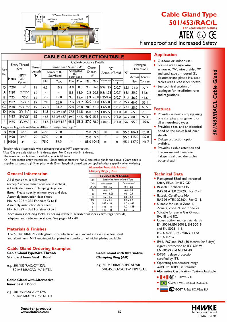
Larger cable glands available in 501/453/L design. See page 23.
Flameproof EExd and Increased Safety EExe. II 2 GD Baseefa Certificate No. BAS 01 ATEX 2072X. For O - F. Baseefa Certificate No. BAS 01 ATEX 2296X. For G - J. Suitable for use in Zone 1, Zone 2, Zone 21 and Zone 22. Suitable for use in Gas Groups IIA, IIB and IIC.
IP66, IP67 and IP68 (30 metres for 7 days) ingress protection to IEC 60529, EN 60529 and NEMA 4X. DTS01 deluge protection certified by ITS. Operating temperature range -60°C to +80°C as standard.
Alternative Certification Options Available.
Construction and test standardsEN 50014, EN 50018, EN 50019 and EN 50281-1-1.IEC 60079-0, IEC 60079-1 and IEC 60079-7.
GOST R-Exd IICU/Exe IIU.
BR-Exd IIC/Exe II.
Exd IIC/Exe II.
The 501/453/RAC/L cable gland is manufactured as standard in brass, stainless steeland aluminium. NPT entries, nickel plated as standard. Full nickel plating available.
All dimensions in millimetres(except* where dimensions are in inches).# Dedicated armour clamping rings arefitted. Please specify armour type and size.Assembly instruction data sheet No. A.I. 302 + 336 For sizes O to F.Assembly instruction data sheet No. A.I. 329 + 336 For sizes G to J.Accessories including locknuts, sealing washers, serrated washers, earth tags, shrouds,adaptors and reducers available. See pages 44 - 48.
0.8 - 1.0 0.4 - 0.80.8 - 1.0 0.4 - 0.80.9 - 1.25 0.5 - 0.91.2 - 1.6 0.6 - 1.21.2 - 1.6 0.6 - 1.2
1.45 - 1.8 1.0 - 1.45 1.0 - 1.45 1.0 - 1.45
1.45 - 1.8 1.45 - 1.8
SELECTION TABLE
AO/Os
BC
DEF
C2
SizeRef.
Steel Wire Armour/Braid/TapeOrientation 1 Orientation 2
Alternative Reversible ArmourClamping Rings (RAC)
Alternative
Min. Max.
Size O is available with an M16 thread size. For O size with M16 thread, the maximum cable inner sheath diameter is 10.9mm. O - F size metric entry threads are 1.5mm pitch as standard. For G size cable glands and above, a 2mm pitch is supplied as standard (1.5mm pitch with 15mm length of thread can be supplied) please specifiy when ordering.
Outdoor or Indoor use. For use with single wire armoured 'W', wire braided 'X' and steel tape armoured 'Z', elastomer and plastic insulated cables with a lead inner sheath.
See technical section of catalogue for installation rules and regulations.
Provides armour clamping using one clamping arrangement for all armour/braid types. Provides a seal and an electrical bond on the cables lead inner sheath. Deluge protection option available.
Provides a cable retention and low smoke and fume, zerohalogen seal onto the cables outer sheath.
Seal+Bond(K)
2
InternationalSmarter productswww.ehawke.com
CABLE GLAND SELECTION TABLE
SizeRef.
OABCC2DE
F
M20M20M25M32M40M50M63
M75
¾"/½"
2"/1½"2½"/2"
3"/2½"
½"
1"/¾"1¼"/1"
1½"/1¼"
Entry ThreadSize
MetricNPT*
OuterSheath
'B'
Cable Acceptance Details
Min. Max.Max.Std./
OptionOrientation
2Orientation
1
'G'AcrossFlats
AcrossCorners
HexagonDimensions'C'
Armour/Braid
24.030.036.046.0
55.065.080.095.0
27.734.6
41.653.163.575.192.4109.6
65.166.171.4
77.190.3
9.5
12.516.922.0
28.036.046.057.0
16.0
Min.
20.526.033.041.052.665.378.0
0.9/1.25
0.9/1.251.25/1.61.6/2.01.6/2.01.8/2.51.8/2.51.8/2.5
0/0.70/0.70/0.70/0.70/0.70/1.00/1.00/1.0
75.2
96.796
HJ
M80M90M100
3½"3½"
4"
106.4115.0127.0
123.0132.8146.7
G 89.589.5104.5
95.695.695.6
###
###
Inner Lead Sheath 'A'Standard (L)Seal+Bond
67.067.075.0
70.075.089.5
75.075.088.0
-
-- -- -
-
-4.0 8.06.5
12.519.025.031.542.554.5
10.5
19.0
25.031.2
42.3/42.853.3/54.566.0/64.3
9.514.522.027.539.048.5
15.48.5 13.0
21.228.034.8
46.558.3
2
ThreadLength
'H'
15
151515151515
15
202020
AR/354/105
dnalG elba
C L/C
Flameproof and Increased Safety
501/453/RAC/L Cable Gland Type
For Lead Sheath Cables
ATEX
Technical DataGeneral Information
Features
Application
Materials & Finishes
Cable Gland Ordering ExamplesCable Gland Type/Size/Thread/Standard Inner Seal + Bond
e.g. 501/453/RAC/C/M32/L 501/453/RAC/C/1¼" NPT/L
Cable Gland with AlternativeInner Seal + Bond
e.g. 501/453/RAC/C/M32/K 501/453/RAC/C/1¼" NPT/K
Cable Gland with AlternativeClamping Ring (AR)
e.g. 501/453/RAC/C/M32/L/AR 501/453/RAC/C/1¼" NPT/L/AR
HWK21 Feb '04
Armour/Braid'C'
'B' Ø
'A'
Ø
Entr
yThr
dae
MetricEntry
Lead Sheath Bond
'H' 'G' Approx (Compressed Length)
1
1
1
Smaller value is applicable when selecting reduced NPT entry option.1
15
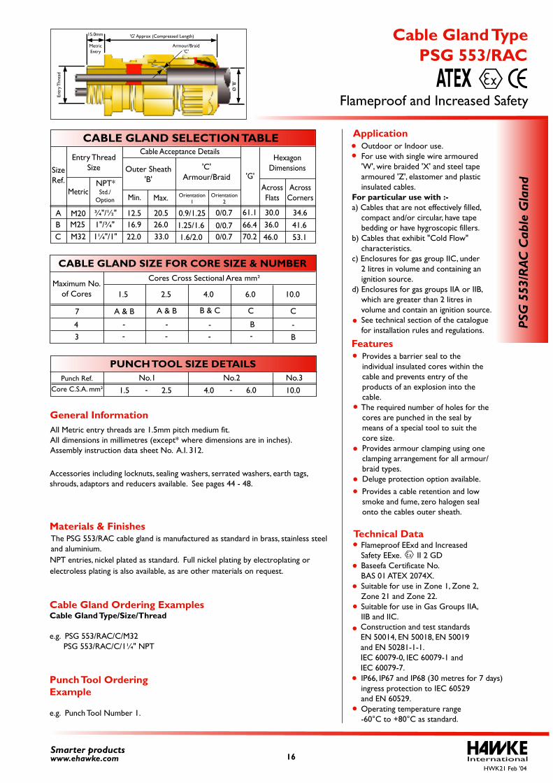
Flameproof EExd and Increased Safety EExe. II 2 GD Baseefa Certificate No. BAS 01 ATEX 2074X. Suitable for use in Zone 1, Zone 2, Zone 21 and Zone 22. Suitable for use in Gas Groups IIA, IIB and IIC.
IP66, IP67 and IP68 (30 metres for 7 days) ingress protection to IEC 60529 and EN 60529. Operating temperature range -60°C to +80°C as standard.
Construction and test standards EN 50014, EN 50018, EN 50019 and EN 50281-1-1.IEC 60079-0, IEC 60079-1 and IEC 60079-7.
The PSG 553/RAC cable gland is manufactured as standard in brass, stainless steeland aluminium.
All Metric entry threads are 1.5mm pitch medium fit.All dimensions in millimetres (except* where dimensions are in inches).Assembly instruction data sheet No. A.I. 312.
Accessories including locknuts, sealing washers, serrated washers, earth tags, shrouds, adaptors and reducers available. See pages 44 - 48.
Provides a barrier seal to the individual insulated cores within the cable and prevents entry of the products of an explosion into the cable. The required number of holes for the cores are punched in the seal by means of a special tool to suit the core size. Provides armour clamping using one clamping arrangement for all armour/ braid types. Deluge protection option available.
Provides a cable retention and low smoke and fume, zero halogen seal onto the cables outer sheath.
Punch Tool Ordering Example
e.g. Punch Tool Number 1.
Cable Gland Ordering ExamplesCable Gland Type/Size/Thread
e.g. PSG 553/RAC/C/M32 PSG 553/RAC/C/1¼" NPT
Outdoor or Indoor use. For use with single wire armoured 'W', wire braided 'X' and steel tape armoured 'Z', elastomer and plastic insulated cables.For particular use with :-a) Cables that are not effectively filled, compact and/or circular, have tape bedding or have hygroscopic fillers.b) Cables that exhibit "Cold Flow" characteristics.c) Enclosures for gas group IIC, under 2 litres in volume and containing an ignition source.d) Enclosures for gas groups IIA or IIB, which are greater than 2 litres in volume and contain an ignition source. See technical section of the catalogue for installation rules and regulations.
International16Smarter productswww.ehawke.com
CABLE GLAND SELECTION TABLE
SizeRef.
ABC
M20M25M32
¾"/½"1"/¾"1¼"/1"
Entry ThreadSize
MetricNPT*
Cable Acceptance Details
Max.Std./
OptionOrientation
2Orientation
1
'G'AcrossFlats
AcrossCorners
HexagonDimensions'C'
Armour/Braid
36.046.0
41.653.1
30.0 34.661.166.470.2
Min.
1.25/1.61.6/2.0
0/0.70.9/1.25 0/0.7
0/0.7
Outer Sheath'B'
12.516.9
22.026.033.0
20.5
CABLE GLAND SIZE FOR CORE SIZE & NUMBER
Maximum No.of Cores
A & B7
43
1.5 2.5
Cores Cross Sectional Area mm²
4.0 6.0 10.0
---
--
- -
---
PUNCH TOOL SIZE DETAILSPunch Ref.
Core C.S.A. mm²No.1 No.2 No.3
1.5 2.5 4.0 6.0 10.0
A & B B & C C
B
C
B
PSG
553
/RAC
Cab
le G
land
Flameproof and Increased Safety
PSG 553/RAC Cable Gland Type
ATEX
Technical Data
General Information
Features
Materials & Finishes
Application
HWK21 Feb '04
'G' Approx (Compressed Length)15.0mm
MetricEntry
Entr
y Thr
ead
Ø 'B
'
Armour/Braid'C'
electroless plating is also available, as are other materials on request.NPT entries, nickel plated as standard. Full nickel plating by electroplating or
Flameproof EExd and Increased Safety EExe. II 2 GD Baseefa Certificate No. BAS 01 ATEX 2079X. Suitable for use in Zone 1, Zone 2, Zone 21 and Zone 22. Suitable for use in Gas Groups IIA, IIB and IIC.
IP66, IP67 and IP68 (30 metres for 7 days) ingress protection to IEC 60529, EN 60529 and NEMA 4X. DTS01 deluge protection certified by ITS. Operating temperature range -60°C to +80°C as standard. Alternative Certification Options Available.
Construction and test standards EN 50014, EN 50018, EN 50019 and EN 50281-1-1.IEC 60079-0, IEC 60079-1 and IEC 60079-7.
BR-Exd IIC/Exe II.
Exd IIC/Exe II.
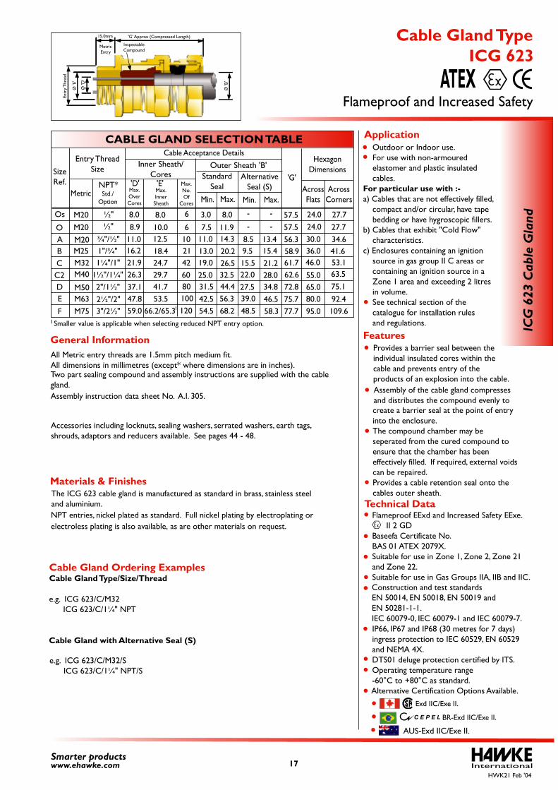
create a barrier seal at the point of entry into the enclosure. The compound chamber may be seperated from the cured compound to ensure that the chamber has been effectively filled. If required, external voids can be repaired.Provides a cable retention seal onto the cables outer sheath.
Assembly of the cable gland compresses and distributes the compound evenly to
Provides a barrier seal between the individual insulated cores within the cable and prevents entry of the products of an explosion into the cable.
The ICG 623 cable gland is manufactured as standard in brass, stainless steel and aluminium.
Two part sealing compound and assembly instructions are supplied with the cable gland.
All Metric entry threads are 1.5mm pitch medium fit.All dimensions in millimetres (except* where dimensions are in inches).
Assembly instruction data sheet No. A.I. 305.
Accessories including locknuts, sealing washers, serrated washers, earth tags, shrouds, adaptors and reducers available. See pages 44 - 48.
Outdoor or Indoor use. For use with non-armoured elastomer and plastic insulated cables.For particular use with :-a) Cables that are not effectively filled, compact and/or circular, have tape bedding or have hygroscopic fillers.b) Cables that exhibit "Cold Flow" characteristics.c) Enclosures containing an ignition source in gas group II C areas or containing an ignition source in a Zone 1 area and exceeding 2 litres in volume. See technical section of the catalogue for installation rules and regulations.
International17Smarter productswww.ehawke.com
CABLE GLAND SELECTION TABLE
SizeRef.
O
Os
ABCC2DE
F
M20M20M25M32M40
M50M63M75
¾"/½"
M20 ½"
2"/1½"2½"/2"3"/2½"
11.016.221.926.337.147.859.0
12.518.424.729.741.753.5
66.2/65.3
8.9 10.0 6
8.0 8.0 6
1021426080100120
½"
1"/¾"1¼"/1"
1½"/1¼"
Entry ThreadSize
MetricNPT*
Inner Sheath/Cores
Outer Sheath 'B'Cable Acceptance Details
Min. Max.
Max.No.Of
Cores
Max.OverCores
Max.Inner
Sheath
Std./Option
'G'AcrossFlats
AcrossCorners
HexagonDimensions
24.030.036.046.0
55.065.080.095.0
27.734.641.653.163.575.192.4109.6
57.524.0 27.757.5
56.358.9
62.672.8
7.511.013.019.025.031.542.554.5
11.9
3.0 8.0
14.320.226.532.544.456.368.2
8.5 9.515.522.027.539.048.5
13.415.421.228.034.846.5 58.3
61.7
75.7 77.7
'D' 'E'
Min. Max.
StandardSeal
AlternativeSeal (S)
- -
- -
ICG
623
Cab
le G
land
Flameproof and Increased Safety
ICG 623 Cable Gland Type
ATEX
Technical Data
General Information Features
Application
Materials & Finishes
Cable Gland Ordering ExamplesCable Gland Type/Size/Thread
e.g. ICG 623/C/M32 ICG 623/C/1¼" NPT
Cable Gland with Alternative Seal (S)
e.g. ICG 623/C/M32/S ICG 623/C/1¼" NPT/S
HWK21 Feb '04
'G' Approx (Compressed Length)15.0mm
MetricEntry
Ø 'B
'
Ø 'D
'
Entr
y Thr
ead
Ø 'E
'
InspectableCompound
AUS-Exd IIC/Exe II.
1
Smaller value is applicable when selecting reduced NPT entry option. 1
electroless plating is also available, as are other materials on request.NPT entries, nickel plated as standard. Full nickel plating by electroplating or
Flameproof EExd and Increased Safety EExe. II 2 GD Baseefa Certificate No. BAS 01 ATEX 2080X. Suitable for use in Zone 1, Zone 2, Zone 21 and Zone 22. Suitable for use in Gas Groups IIA, IIB and IIC.
IP66, IP67 and IP68 (30 metres for 7 days) ingress protection to IEC 60529, EN 60529 and NEMA 4X. DTS01 deluge protection certified by ITS. Operating temperature range -60°C to +80°C as standard. Alternative Certification Options Available.
Construction and test standards EN 50014, EN 50018, EN 50019 and EN 50281-1-1.IEC 60079-0, IEC 60079-1 and IEC 60079-7.
GOST R-Exd IICU/Exe IIU.
BR-Exd IIC/Exe II.
Exd IIC/Exe II.
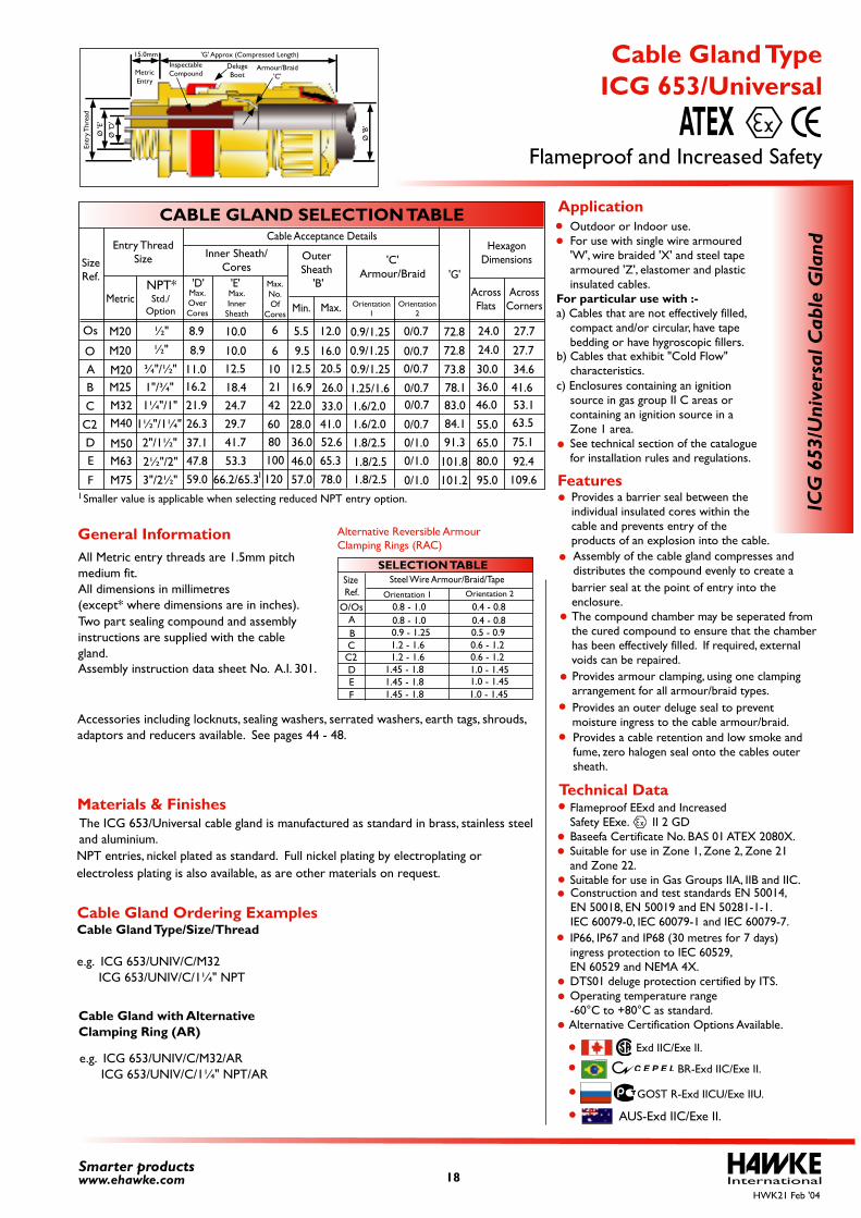
Provides an outer deluge seal to prevent moisture ingress to the cable armour/braid.
Provides a cable retention and low smoke and fume, zero halogen seal onto the cables outer sheath.
Provides armour clamping, using one clamping arrangement for all armour/braid types.
The ICG 653/Universal cable gland is manufactured as standard in brass, stainless steeland aluminium.
Two part sealing compound and assemblyinstructions are supplied with the cablegland.
All Metric entry threads are 1.5mm pitch medium fit.All dimensions in millimetres (except* where dimensions are in inches).
Assembly instruction data sheet No. A.I. 301.
Accessories including locknuts, sealing washers, serrated washers, earth tags, shrouds, adaptors and reducers available. See pages 44 - 48.
0.8 - 1.0 0.4 - 0.80.8 - 1.0 0.4 - 0.80.9 - 1.25 0.5 - 0.91.2 - 1.6 0.6 - 1.21.2 - 1.6 0.6 - 1.2
1.45 - 1.8 1.0 - 1.45 1.0 - 1.45 1.0 - 1.45
1.45 - 1.8 1.45 - 1.8
SELECTION TABLE
AO/Os
BC
DEF
C2
Size Ref.
Steel Wire Armour/Braid/TapeOrientation 1 Orientation 2
Alternative Reversible Armour Clamping Rings (RAC)
Outdoor or Indoor use. For use with single wire armoured 'W', wire braided 'X' and steel tape armoured 'Z', elastomer and plastic insulated cables.For particular use with :-a) Cables that are not effectively filled, compact and/or circular, have tape bedding or have hygroscopic fillers.
c) Enclosures containing an ignition source in gas group II C areas or containing an ignition source in a Zone 1 area. See technical section of the catalogue for installation rules and regulations.
barrier seal at the point of entry into the enclosure. The compound chamber may be seperated from the cured compound to ensure that the chamber has been effectively filled. If required, external voids can be repaired.
Assembly of the cable gland compresses and distributes the compound evenly to create a
Provides a barrier seal between the individual insulated cores within the cable and prevents entry of the products of an explosion into the cable.
Features
b) Cables that exhibit "Cold Flow" characteristics.
Smaller value is applicable when selecting reduced NPT entry option. 1
International18Smarter productswww.ehawke.com
CABLE GLAND SELECTION TABLE
SizeRef.
O
Os
AB
C
C2DE
F
M20
M20M25M32M40
M50M63
M75
¾"/½"
M20 ½"
2"/1½"
2½"/2"3"/2½"
11.016.2
21.926.3
37.147.859.0
12.5
18.424.7
29.741.7
53.3
66.2/65.3
8.9 10.0 6
8.9 10.0 6
102142
6080100
120
½"
1"/¾"1¼"/1"
1½"/1¼"
Entry ThreadSize
MetricNPT*
Inner Sheath/Cores
Outer Sheath
'B'
Cable Acceptance Details
Min. Max.
Max.No.Of
Cores
Max.OverCores
Max.Inner
Sheath
Std./Option
Orientation2
Orientation1
'G'
AcrossFlats
AcrossCorners
HexagonDimensions'C'
Armour/Braid
24.0
30.036.046.0
55.065.080.0
95.0
27.7
34.641.653.163.5
75.1
92.4
109.6
72.8
24.0 27.772.8
73.878.1
84.1
91.3
9.512.5
16.922.0
28.036.0
46.057.0
16.0
5.5 12.0
20.5
26.0
33.041.052.6
65.3
78.0
0.9/1.25
0.9/1.25
1.25/1.61.6/2.01.6/2.0
1.8/2.5
1.8/2.51.8/2.5
0/0.7
0.9/1.25 0/0.7
0/0.7
0/0.70/0.7
0/0.70/1.00/1.0
0/1.0
83.0
101.8
101.2
'D' 'E'
1
ICG
653
/Uni
vers
al C
able
Gla
nd
Flameproof and Increased Safety
ICG 653/Universal Cable Gland Type
ATEX
Cable Gland with Alternative Clamping Ring (AR)
e.g. ICG 653/UNIV/C/M32/AR ICG 653/UNIV/C/1¼" NPT/AR
AUS-Exd IIC/Exe II.
Technical Data
General Information
Application
Materials & Finishes
Cable Gland Ordering ExamplesCable Gland Type/Size/Thread
e.g. ICG 653/UNIV/C/M32 ICG 653/UNIV/C/1¼" NPT
HWK21 Feb '04
'G' Approx (Compressed Length)15.0mm
MetricEntry
DelugeBoot
Ø 'B
'
Armour/Braid'C'
Ø 'D
'
Entr
y Thr
ead
Ø 'E
'
InspectableCompound
electroless plating is also available, as are other materials on request.NPT entries, nickel plated as standard. Full nickel plating by electroplating or
Flameproof EExd and Increased Safety EExe. II 2 GD Baseefa Certificate No. BAS 01 ATEX 2080X. Suitable for use in Zone 1, Zone 2, Zone 21 and Zone 22. Suitable for use in Gas Groups IIA, IIB and IIC.
IP66, IP67 and IP68 (30 metres for 7 days) ingress protection to IEC 60529, EN 60529 and NEMA 4X. DTS01 deluge protection certified by ITS. Operating temperature range -60°C to +80°C as standard.
Alternative Certification Options Available.
Construction and test standards EN 50014,EN 50018, EN 50019 and EN 50281-1-1.IEC 60079-0, IEC 60079-1 and IEC 60079-7.
GOST R-Exd IICU/Exe IIU.
BR-Exd IIC/Exe II.
Exd IIC/Exe II.
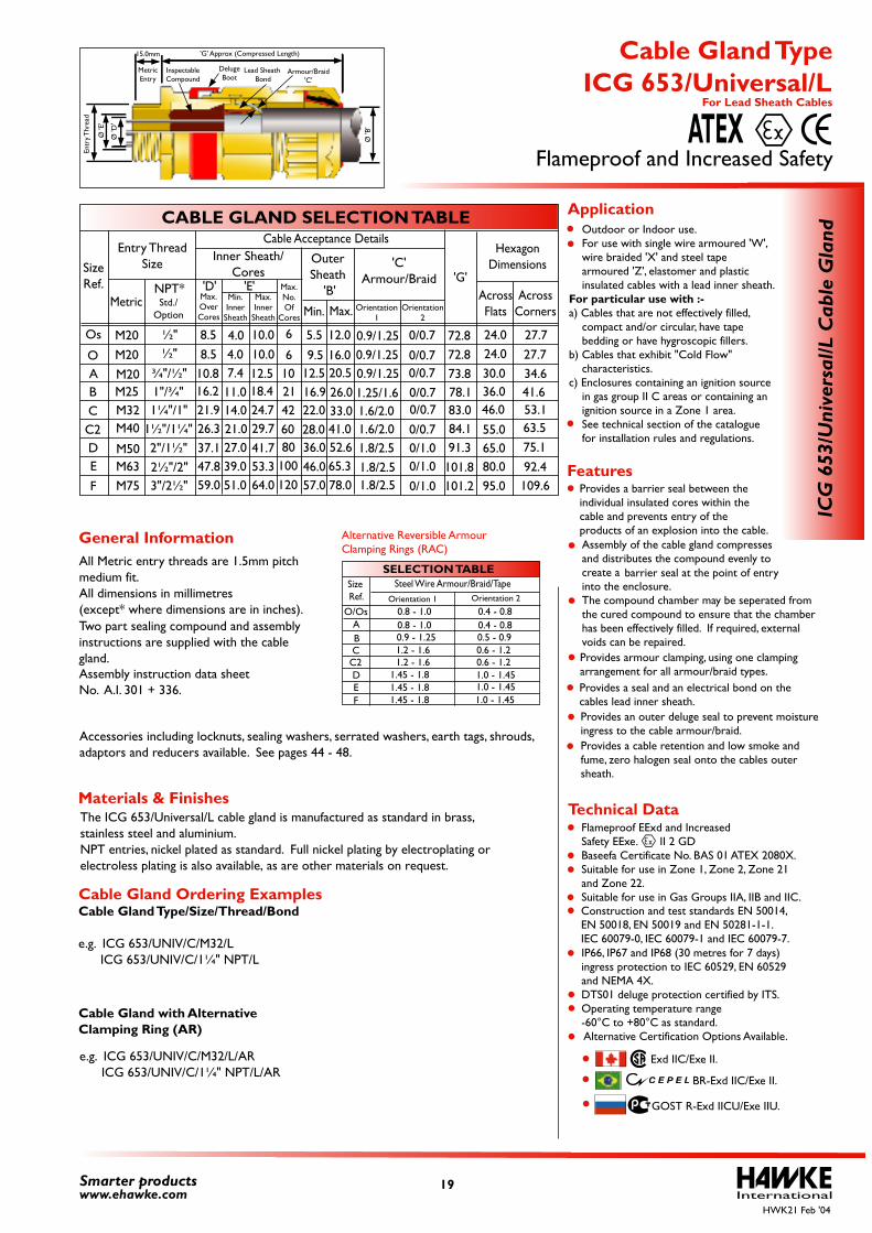
Provides a seal and an electrical bond on the cables lead inner sheath.
Provides a cable retention and low smoke and fume, zero halogen seal onto the cables outer sheath.
into the enclosure.The compound chamber may be seperated fromthe cured compound to ensure that the chamber has been effectively filled. If required, external voids can be repaired.
Assembly of the cable gland compressesand distributes the compound evenly to create a
Provides armour clamping, using one clamping arrangement for all armour/braid types.
Provides a barrier seal between the individual insulated cores within the cable and prevents entry of the products of an explosion into the cable.
The ICG 653/Universal/L cable gland is manufactured as standard in brass,stainless steel and aluminium.NPT entries, nickel plated as standard. Full nickel plating by electroplating or
Two part sealing compound and assemblyinstructions are supplied with the cablegland.
All Metric entry threads are 1.5mm pitch medium fit.All dimensions in millimetres(except* where dimensions are in inches).
Assembly instruction data sheet No. A.I. 301 + 336.
Accessories including locknuts, sealing washers, serrated washers, earth tags, shrouds,adaptors and reducers available. See pages 44 - 48.
0.8 - 1.0 0.4 - 0.80.8 - 1.0 0.4 - 0.80.9 - 1.25 0.5 - 0.91.2 - 1.6 0.6 - 1.21.2 - 1.6 0.6 - 1.2
1.45 - 1.8 1.0 - 1.45 1.0 - 1.45 1.0 - 1.45
1.45 - 1.8 1.45 - 1.8
SELECTION TABLE
AO/Os
BC
DEF
C2
SizeRef.
Steel Wire Armour/Braid/TapeOrientation 1 Orientation 2
Alternative Reversible ArmourClamping Rings (RAC)
Outdoor or Indoor use. For use with single wire armoured 'W', wire braided 'X' and steel tape armoured 'Z', elastomer and plastic insulated cables with a lead inner sheath.For particular use with :-a) Cables that are not effectively filled, compact and/or circular, have tape bedding or have hygroscopic fillers.b) Cables that exhibit "Cold Flow" characteristics.c) Enclosures containing an ignition source in gas group II C areas or containing an ignition source in a Zone 1 area. See technical section of the catalogue for installation rules and regulations.
Provides an outer deluge seal to prevent moisture ingress to the cable armour/braid.
barrier seal at the point of entry
InternationalSmarter productswww.ehawke.com
CABLE GLAND SELECTION TABLE
SizeRef.
O
Os
ABCC2DE
F
M20M20M25M32M40
M50M63M75
¾"/½"
M20 ½"
2"/1½"2½"/2"3"/2½"
10.816.221.926.337.147.859.0
7.411.014.021.027.039.051.0
8.5 6
8.5
12.518.424.729.741.753.364.0
10.010.04.0
4.0
6
1021426080
100120
½"
1"/¾"1¼"/1"
1½"/1¼"
Entry ThreadSize
MetricNPT*
Inner Sheath/Cores
OuterSheath
'B'
Cable Acceptance Details
Min. Max.
Max.No.Of
Cores
Max.OverCores
Min.Inner
Sheath
Max.Inner
Sheath
Std./Option
Orientation2
Orientation1
'G'AcrossFlats
AcrossCorners
HexagonDimensions'C'
Armour/Braid
24.030.036.046.0
55.065.080.095.0
27.734.641.653.163.575.192.4109.6
72.824.0 27.772.8
73.878.1
84.191.3
9.512.516.922.028.036.046.057.0
16.0
5.5 12.0
20.526.033.041.052.665.378.0
0.9/1.250.9/1.251.25/1.61.6/2.01.6/2.01.8/2.51.8/2.51.8/2.5
0/0.70.9/1.25 0/0.7
0/0.70/0.70/0.70/0.70/1.00/1.00/1.0
83.0
101.8101.2
'D' 'E'
For Lead Sheath Cables
vinU/356
GCI
rednal
G elbaC L/las
Flameproof and Increased Safety
ICG 653/Universal/L Cable Gland Type
ATEX
Technical Data
General Information
Features
Application
Materials & Finishes
Cable Gland Ordering ExamplesCable Gland Type/Size/Thread/Bond
e.g. ICG 653/UNIV/C/M32/L ICG 653/UNIV/C/1¼" NPT/L
Cable Gland with AlternativeClamping Ring (AR)
e.g. ICG 653/UNIV/C/M32/L/AR ICG 653/UNIV/C/1¼" NPT/L/AR
HWK21 Feb '04
B' Ø
'
'G' Approx (Compressed Length)
InspectableCompound
'E' Ø
DelugeBoot
Lead Sheath Bond
EnrtyT
hrdae
15.0mm
MetricEntry
'D'
Ø
Armour/Braid'C'
electroless plating is also available, as are other materials on request.
19
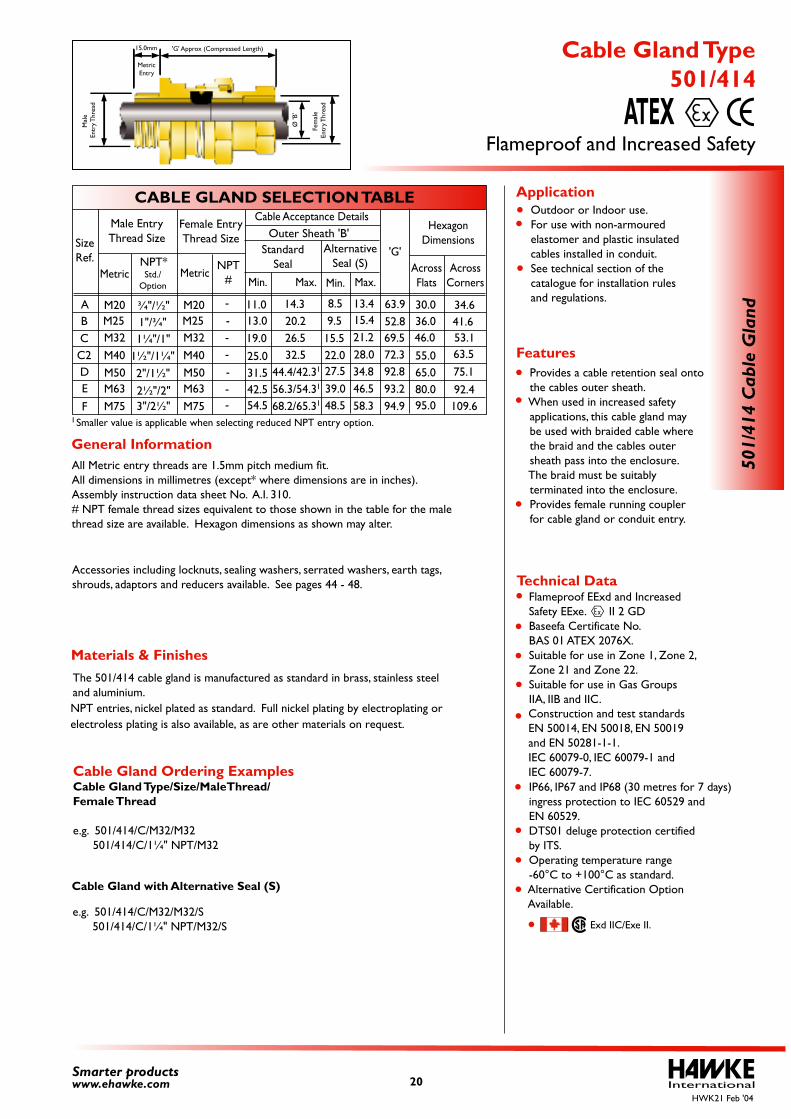
Flameproof EExd and Increased Safety EExe. II 2 GD Baseefa Certificate No. BAS 01 ATEX 2076X. Suitable for use in Zone 1, Zone 2, Zone 21 and Zone 22. Suitable for use in Gas Groups IIA, IIB and IIC.
IP66, IP67 and IP68 (30 metres for 7 days) ingress protection to IEC 60529 and EN 60529. DTS01 deluge protection certified by ITS. Operating temperature range -60°C to +100°C as standard. Alternative Certification Option Available.
Construction and test standards EN 50014, EN 50018, EN 50019 and EN 50281-1-1.IEC 60079-0, IEC 60079-1 and IEC 60079-7.
Exd IIC/Exe II.
The 501/414 cable gland is manufactured as standard in brass, stainless steeland aluminium.
All Metric entry threads are 1.5mm pitch medium fit.All dimensions in millimetres (except* where dimensions are in inches).Assembly instruction data sheet No. A.I. 310.# NPT female thread sizes equivalent to those shown in the table for the male thread size are available. Hexagon dimensions as shown may alter.
Accessories including locknuts, sealing washers, serrated washers, earth tags, shrouds, adaptors and reducers available. See pages 44 - 48.
Outdoor or Indoor use. For use with non-armoured elastomer and plastic insulated cables installed in conduit. See technical section of the catalogue for installation rules and regulations.
Provides a cable retention seal onto the cables outer sheath. When used in increased safety applications, this cable gland may be used with braided cable where the braid and the cables outer sheath pass into the enclosure. The braid must be suitably terminated into the enclosure. Provides female running coupler for cable gland or conduit entry.
Cable Gland Ordering ExamplesCable Gland Type/Size/MaleThread/Female Thread
e.g. 501/414/C/M32/M32 501/414/C/1¼" NPT/M32
e.g. 501/414/C/M32/M32/S 501/414/C/1¼" NPT/M32/S
Cable Gland with Alternative Seal (S)
--
-
--
--
Smaller value is applicable when selecting reduced NPT entry option. 1
International20Smarter productswww.ehawke.com
CABLE GLAND SELECTION TABLE
SizeRef.
ABCC2DE
F
M20M25M32M40M50M63M75
M20M25M32M40M50M63M75
¾"/½"
2"/1½"2½"/2"3"/2½"
1"/¾"1¼"/1"
1½"/1¼"
Male EntryThread Size
MetricNPT*
Cable Acceptance Details
Min. Max.Std./
Option
Female EntryThread Size
MetricNPT
#
'G'AcrossFlats
AcrossCorners
HexagonDimensions
30.036.046.0
55.065.080.095.0
34.641.653.163.575.192.4109.6
11.013.019.025.031.542.554.5
14.320.226.532.5
44.4/42.356.3/54.368.2/65.3
8.59.5
15.522.027.539.048.5
13.415.421.228.034.846.558.3
63.952.869.572.392.893.294.9
Min. Max.
Outer Sheath 'B'Standard
SealAlternative
Seal (S)
1
1
1
501/
414
Cab
le G
land
Flameproof and Increased Safety
501/414 Cable Gland Type
ATEX
Technical Data
General Information
Features
Application
Materials & Finishes
HWK21 Feb '04
'G' Approx (Compressed Length)15.0mm
MetricEntry
Ø 'B
'
Fem
ale
Entr
y Thr
ead
Mal
e En
try T
hrea
d
electroless plating is also available, as are other materials on request.NPT entries, nickel plated as standard. Full nickel plating by electroplating or
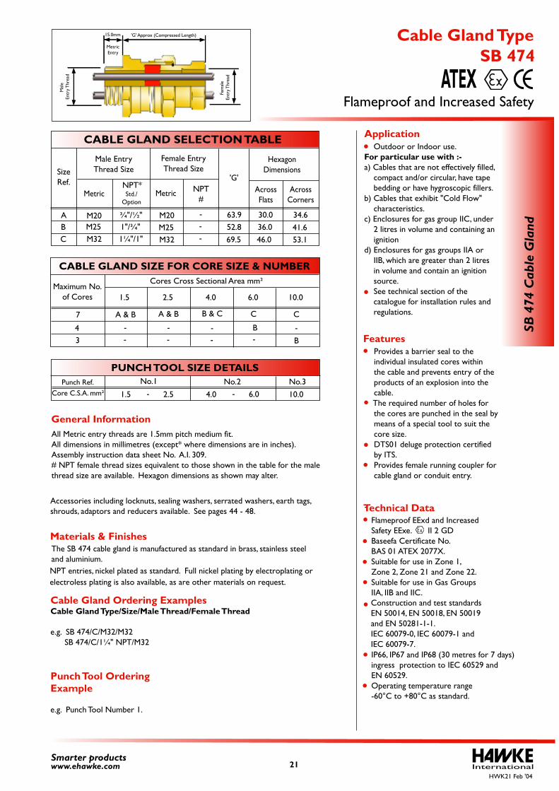
Flameproof EExd and Increased Safety EExe. II 2 GD Baseefa Certificate No. BAS 01 ATEX 2077X. Suitable for use in Zone 1, Zone 2, Zone 21 and Zone 22. Suitable for use in Gas Groups IIA, IIB and IIC.
IP66, IP67 and IP68 (30 metres for 7 days) ingress protection to IEC 60529 and EN 60529. Operating temperature range -60°C to +80°C as standard.
Construction and test standards EN 50014, EN 50018, EN 50019 and EN 50281-1-1.IEC 60079-0, IEC 60079-1 and IEC 60079-7.
The SB 474 cable gland is manufactured as standard in brass, stainless steeland aluminium.
Accessories including locknuts, sealing washers, serrated washers, earth tags, shrouds, adaptors and reducers available. See pages 44 - 48.
Provides a barrier seal to the individual insulated cores within the cable and prevents entry of the products of an explosion into the cable. The required number of holes for the cores are punched in the seal by means of a special tool to suit the core size. DTS01 deluge protection certified by ITS. Provides female running coupler for cable gland or conduit entry.
-
Punch Tool Ordering Example
e.g. Punch Tool Number 1.
Cable Gland Ordering ExamplesCable Gland Type/Size/Male Thread/Female Thread
e.g. SB 474/C/M32/M32 SB 474/C/1¼" NPT/M32
Outdoor or Indoor use.For particular use with :-a) Cables that are not effectively filled, compact and/or circular, have tape bedding or have hygroscopic fillers.b) Cables that exhibit "Cold Flow" characteristics.c) Enclosures for gas group IIC, under 2 litres in volume and containing an ignitiond) Enclosures for gas groups IIA or IIB, which are greater than 2 litres in volume and contain an ignition source. See technical section of the catalogue for installation rules and regulations.
All Metric entry threads are 1.5mm pitch medium fit.All dimensions in millimetres (except* where dimensions are in inches).Assembly instruction data sheet No. A.I. 309.# NPT female thread sizes equivalent to those shown in the table for the male thread size are available. Hexagon dimensions as shown may alter.
General Information
International21Smarter productswww.ehawke.com
CABLE GLAND SELECTION TABLE
SizeRef.
ABC
M20M25M32
¾"/½"1"/¾"1¼"/1"
Male EntryThread Size
Female EntryThread Size
Metric
M20M25M32
MetricNPT* NPT
#Std./
Option
AcrossFlats
AcrossCorners
HexagonDimensions
36.046.0
41.653.1
30.0 52.869.5
63.9 34.6
CABLE GLAND SIZE FOR CORE SIZE & NUMBER
Maximum No.of Cores
A & B7
43
1.5 2.5
Cores Cross Sectional Area mm²
4.0 6.0 10.0
---
--
- -
-
---
--
PUNCH TOOL SIZE DETAILSPunch Ref.
Core C.S.A. mm²
No.1 No.2 No.31.5 2.5 4.0 6.0 10.0
A & B B & C C
B
C
B
'G'
SB 4
74 C
able
Gla
nd
Flameproof and Increased Safety
SB 474 Cable Gland Type
ATEX
Technical Data
Features
Materials & Finishes
Application
HWK21 Feb '04
'G' Approx (Compressed Length)15.0mm
MetricEntry
Mal
e En
try T
hrea
d
Fem
ale
Entr
y Thr
ead
electroless plating is also available, as are other materials on request.NPT entries, nickel plated as standard. Full nickel plating by electroplating or

Flameproof EExd and Increased Safety EExe. II 2 GD Baseefa Certificate No. BAS 01 ATEX 2082X. Suitable for use in Zone 1, Zone 2, Zone 21 and Zone 22. Suitable for use in Gas Groups IIA, IIB and IIC.
IP66, IP67 and IP68 (30 metres for 7 days) ingress protection to IEC 60529, EN 60529 and NEMA 4X. DTS01 deluge protection certified by ITS. Operating temperature range -60°C to +80°C as standard. Alternative Certification Options Available.
Construction and test standards EN 50014, EN 50018, EN 50019 and EN 50281-1-1.IEC 60079-0, IEC 60079-1 and IEC 60079-7.
Exd IIC/Exe II.
seal at the point of entry into the enclosure. The compound chamber may be seperated from the cured compound to ensure that the chamber has been effectively filled. If required, external voids can be repaired.Provides female running coupler for cable gland or conduit entry.
Assembly of the cable gland compresses and distributes the compound evenly to create a barrier
Provides a barrier seal between the individual insulated cores within the cable and prevents entry of the products of an explosion into the cable or conduit. Seals conductors at entry to enclosure via conduit or enables an existing cable gland to be converted to a barrier type cable gland. The device is fitted with a simple compound filled chamber which permits packing around individual insulated conductors.
The CSB 656 cable gland is manufactured as standard in brass, stainless steeland aluminium.
Two part sealing compound and assembly instructions are supplied with the cable gland.
A - F size metric entry threads are 1.5mm pitch as standard. For G size cable glands and above, a 2mm pitch is supplied as standard (1.5mm pitch with 15mm length of thread can be supplied) please specifiy when ordering. All dimensions in millimetres (except* where dimensions are in inches).
Assembly instruction data sheet No. A.I. 311. # NPT female thread sizes equivalent to those shown in the table for the male thread size are available. Hexagon dimensions as shown may alter.
Accessories including locknuts, sealing washers, serrated washers, earth tags, shrouds, adaptors and reducers available. See pages 44 - 48.
Outdoor or Indoor use. For use with conduit incorporating individual insulated conductors orFor particular use with :-a) Cables that are not effectively filled, compact and/or circular, have tape bedding or have hygroscopic fillers.b) Cables that exhibit "Cold Flow" characteristics.c) Enclosures containing an ignition source in gas group II C areas or containing an ignition source in a Zone 1 area and exceeding 2 litres in volume. See technical section of the catalogue for installation rules and regulations.
InternationalSmarter productswww.ehawke.com
CABLE GLAND SELECTION TABLE
SizeRef.
ABCC2DE
F
M20M25M32M40
M50M63M75
¾"/½"
2"/1½"2½"/2"3"/2½"
11.016.221.926.337.147.859.0
12.518.424.729.741.753.566.2
1021426080
100120140160180
1"/¾"1¼"/1"
1½"/1¼"
Male EntryThread Size
Female EntryThread Size
Metric
M20M25M32M40
M50M63M75
MetricNPT* NPT
#
Inner Sheath/Cores
Max.No.Of
Cores
Max.OverCores
Max.Inner
Sheath
Std./Option
'G'AcrossFlats
AcrossCorners
HexagonDimensions
30.036.046.0
55.065.080.095.0
34.641.653.163.575.192.4109.6
106.4115.0127.0
53.553.5
61.463.7
56.0 56.0
65.7
67.7
67.7 67.7
'D' 'E'
--
-
--
-----
ThreadLength
'H'
CSB
656
Cab
le G
land
123.0132.8146.7
H J
M80M90M100
M80M90M100
3½"3½"
4"
G 74.083.093.0
62.870.980.3
15151515151515202020
Flameproof and Increased Safety
CSB 656 Cable Gland Type
ATEX
Technical Data
General Information
Features
Application
Materials & Finishes
Cable Gland Ordering ExamplesCable Gland Type/Size/Male Thread/Female Thread
e.g. CSB 656/C/M32/M32 CSB 656/C/1¼" NPT/M32
HWK21 Feb '04
'G' Approx (Compressed Length)'H'
MetricEntry
Mal
e En
try T
hrea
d
Fem
ale
Entr
y Thr
ead
Ø 'D
'
Ø 'E
'
Allen Grub Screw2mm A/F A-C
2.5mm A/F C2-FInspectable Compound
AUS-Exd IIC/Exe II.
22
electroless plating is also available, as are other materials on request.NPT entries, nickel plated as standard. Full nickel plating by electroplating or
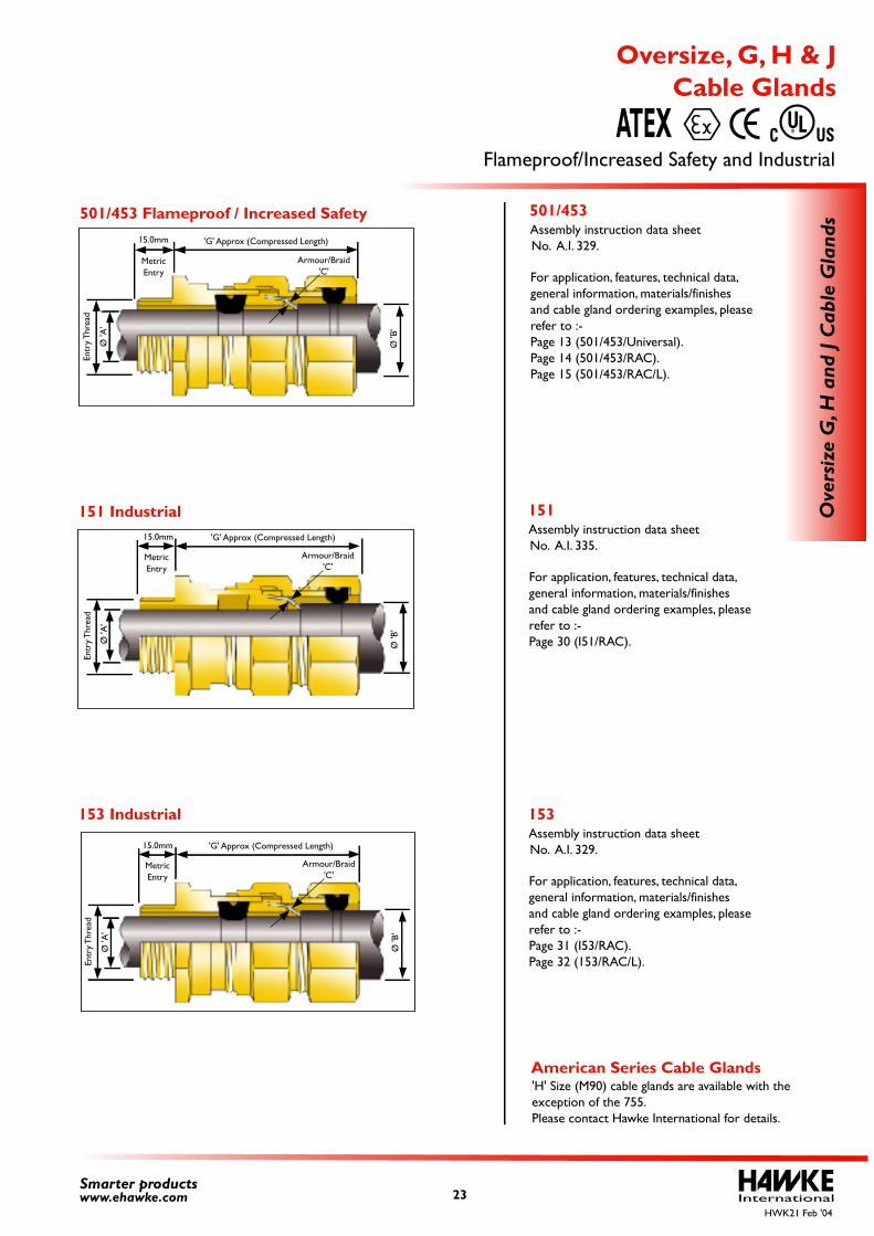
For application, features, technical data, general information, materials/finishes and cable gland ordering examples, please refer to :- Page 13 (501/453/Universal). Page 14 (501/453/RAC). Page 15 (501/453/RAC/L).
For application, features, technical data, general information, materials/finishes and cable gland ordering examples, please refer to :- Page 30 (I51/RAC).
For application, features, technical data, general information, materials/finishes and cable gland ordering examples, please refer to :- Page 31 (I53/RAC). Page 32 (153/RAC/L).
'H' Size (M90) cable glands are available with the exception of the 755. Please contact Hawke International for details.
International23Smarter productswww.ehawke.com
Ove
rsiz
e G
, H a
nd J
Cab
le G
land
s
Cable Glands Oversize, G, H & J
Flameproof/Increased Safety and Industrial ATEX
501/453
151
153
American Series Cable Glands
HWK21 Feb '04
Armour/Braid'C'
Ø 'B
'
Ø 'A
'
Entr
y Thr
ead
MetricEntry
'G' Approx (Compressed Length)
501/453 Flameproof / Increased Safety
151 Industrial
153 Industrial
Armour/Braid'C'
Ø 'B
'
Ø 'A
'
Entr
y Thr
ead
15.0mm
MetricEntry
15.0mm
Armour/Braid'C'
Ø 'B
'
Ø 'A
'
Entr
y Thr
ead
15.0mm
MetricEntry
Assembly instruction data sheet No. A.I. 329.
Assembly instruction data sheet No. A.I. 335.
Assembly instruction data sheet No. A.I. 329.
'G' Approx (Compressed Length)
'G' Approx (Compressed Length)
For application, features, technical data, general information, materials/finishes and cable gland ordering examples, please refer to :- Page 11 (501/421).
For application, features, technical data, general information, materials/finishes and cable gland ordering examples, please refer to :- Page 14 (501/453/RAC). Please note however there is no inner seal with the 351/RAC. This can be seen in the diagram opposite.
For application, features, technical data, general information, materials/finishes and cable gland ordering examples, please refer to :- Page 14 (501/453/RAC).
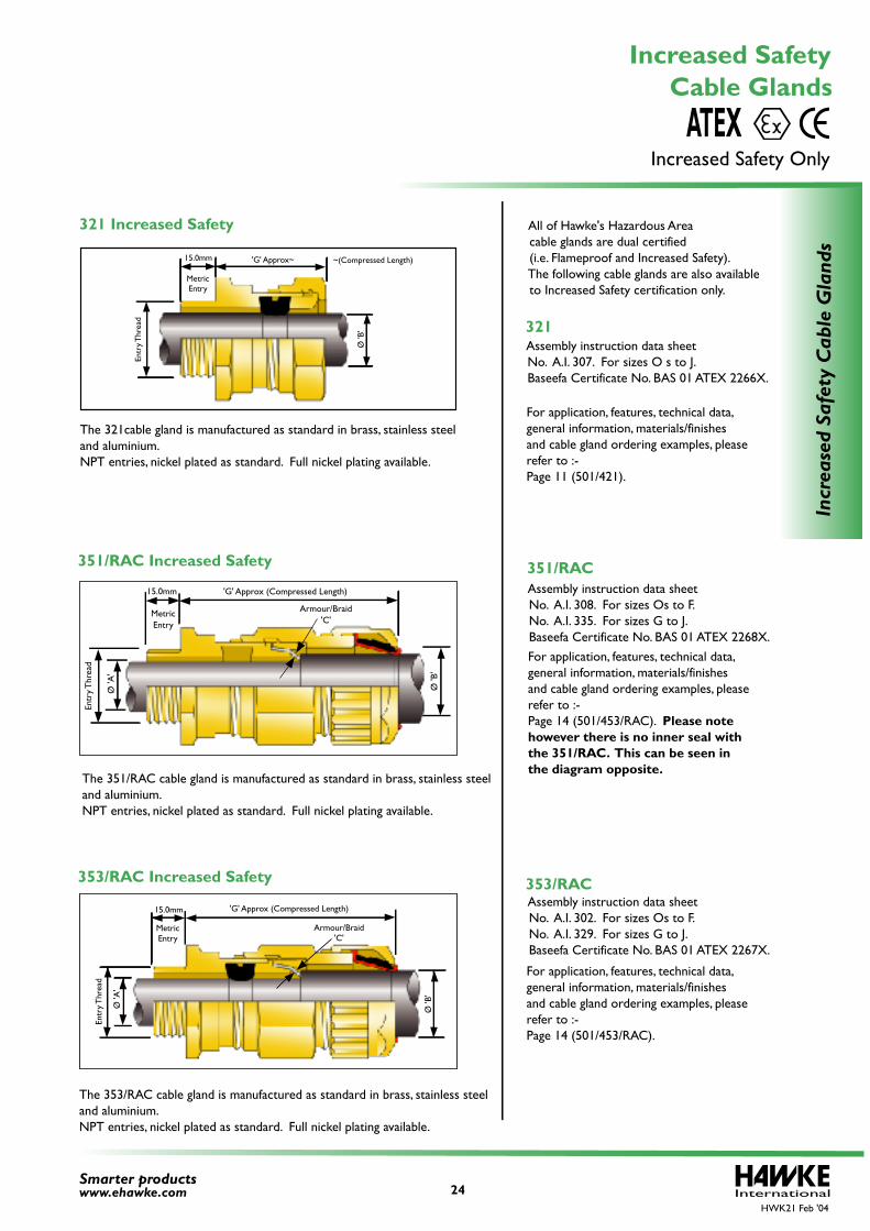
All of Hawke's Hazardous Area cable glands are dual certified (i.e. Flameproof and Increased Safety). The following cable glands are also available to Increased Safety certification only.
The 321cable gland is manufactured as standard in brass, stainless steeland aluminium.NPT entries, nickel plated as standard. Full nickel plating available.
The 351/RAC cable gland is manufactured as standard in brass, stainless steeland aluminium.NPT entries, nickel plated as standard. Full nickel plating available.
The 353/RAC cable gland is manufactured as standard in brass, stainless steeland aluminium.NPT entries, nickel plated as standard. Full nickel plating available.
International24Smarter productswww.ehawke.com
Incr
ease
d Sa
fety
Cab
le G
land
s
Cable Glands Increased Safety
Increased Safety Only ATEX
321
351/RAC
353/RAC
'G' Approx (Compressed Length)15.0mm
MetricEntry
Ø 'B
'
Ø 'A
'
Armour/Braid'C'
Entr
y Thr
ead
'G' Approx~15.0mm
MetricEntry
Ø 'B
'
Entr
y Thr
ead
~(Compressed Length)
Armour/Braid'C'
Ø 'A
'
Entr
y Thr
ead
'G' Approx (Compressed Length)
MetricEntry
Ø 'B
'
15.0mm
HWK21 Feb '04
321 Increased Safety
351/RAC Increased Safety
353/RAC Increased Safety
Assembly instruction data sheet No. A.I. 307. For sizes O s to J. Baseefa Certificate No. BAS 01 ATEX 2266X.
Assembly instruction data sheet No. A.I. 308. For sizes Os to F. No. A.I. 335. For sizes G to J. Baseefa Certificate No. BAS 01 ATEX 2268X.
Assembly instruction data sheet No. A.I. 302. For sizes Os to F. No. A.I. 329. For sizes G to J. Baseefa Certificate No. BAS 01 ATEX 2267X.
InternationalHWK21 Feb '04
25Smarter productswww.ehawke.com
Indu
stri
al C
able
Gla
nds
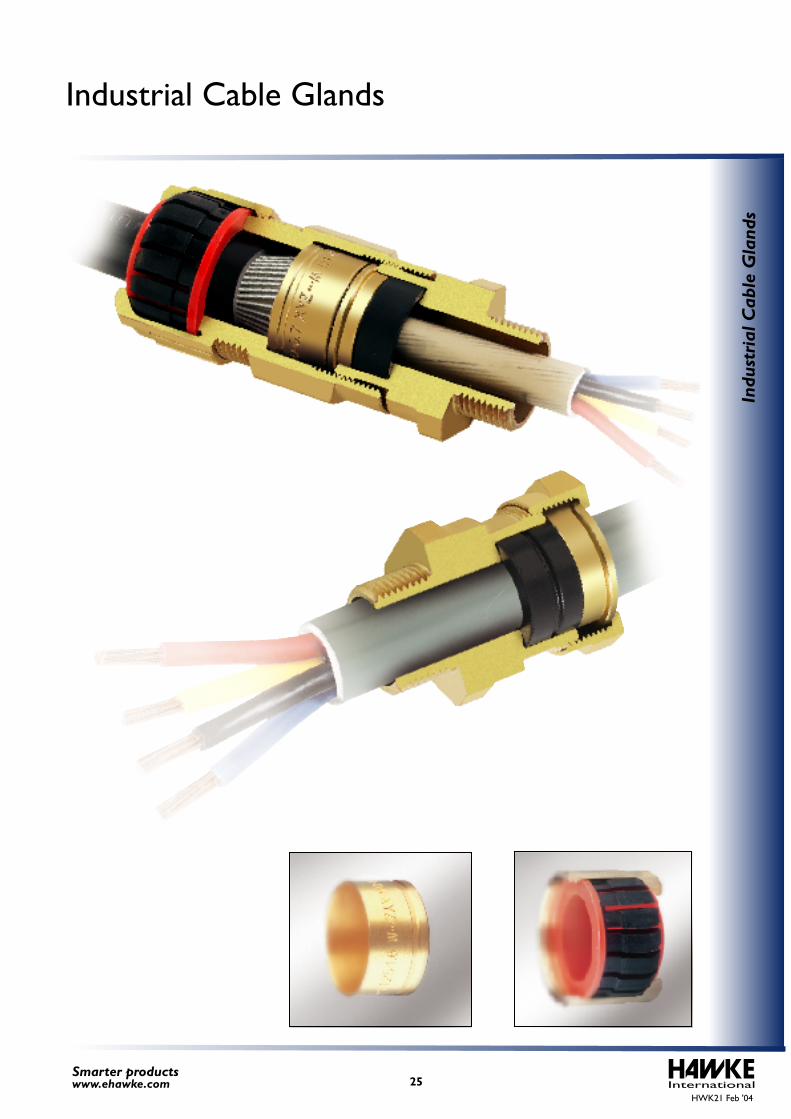
Industrial Cable Glands
Features
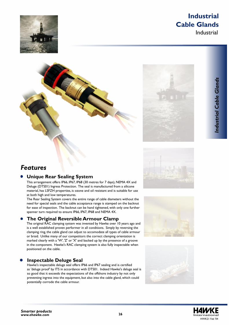
This arrangement offers IP66, IP67, IP68 (30 metres for 7 days), NEMA 4X and Deluge (DTS01) Ingress Protection. The seal is manufactured from a silicone material, has LSFZH properties, is ozone and oil resistant and is suitable for use at both high and low temperatures. The Rear Sealing System covers the entire range of cable diameters without theneed for special seals and the cable acceptance range is stamped on the backnut for ease of inspection. The backnut can be hand tightened, with only one further spanner turn required to ensure IP66, IP67, IP68 and NEMA 4X.
The original RAC clamping system was invented by Hawke over 10 years ago andis a well established proven performer in all conditions. Simply by reversing theclamping ring, the cable gland can adjust to accomodate all types of cable armouror braid. Unlike many of our competitors the correct clamping orientation ismarked clearly with a 'W', 'Z' or 'X' and backed up by the presence of a groovein the component. Hawke's RAC clamping system is also fully inspectable whenpositioned on the cable.
Hawke's inspectable deluge seal offers IP66 and IP67 sealing and is certifiedas 'deluge proof' by ITS in accordance with DTS01. Indeed Hawke's deluge seal isso good that it exceeds the expectations of the offshore industry by not only preventing ingress into the equipment, but also into the cable gland, which could potentially corrode the cable armour.
International26Smarter productswww.ehawke.com
Indu
stri
al C
able
Gla
nds
Industrial Cable Glands
Industrial
Unique Rear Sealing System
Inspectable Deluge Seal
The Original Reversible Armour Clamp
HWK21 Feb '04
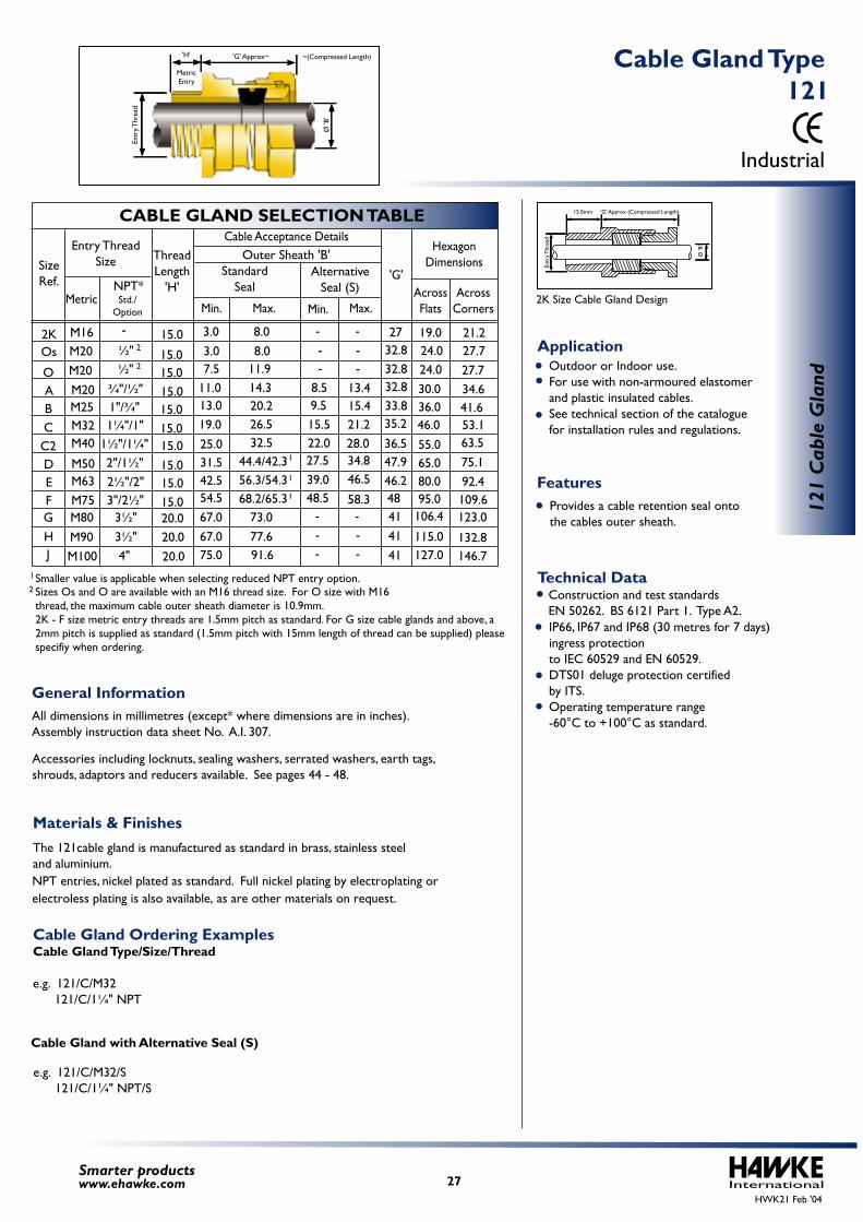
IP66, IP67 and IP68 (30 metres for 7 days) ingress protection to IEC 60529 and EN 60529. DTS01 deluge protection certified by ITS. Operating temperature range -60°C to +100°C as standard.
Construction and test standards EN 50262. BS 6121 Part 1. Type A2.
The 121cable gland is manufactured as standard in brass, stainless steeland aluminium.
All dimensions in millimetres (except* where dimensions are in inches).Assembly instruction data sheet No. A.I. 307.
Accessories including locknuts, sealing washers, serrated washers, earth tags, shrouds, adaptors and reducers available. See pages 44 - 48.
Outdoor or Indoor use. For use with non-armoured elastomer and plastic insulated cables. See technical section of the catalogue for installation rules and regulations.
Provides a cable retention seal onto the cables outer sheath.
Cable Gland Ordering ExamplesCable Gland Type/Size/Thread
e.g. 121/C/M32 121/C/1¼" NPT
e.g. 121/C/M32/S 121/C/1¼" NPT/S
Cable Gland with Alternative Seal (S)
Smaller value is applicable when selecting reduced NPT entry option. 1
2 Sizes Os and O are available with an M16 thread size. For O size with M16 thread, the maximum cable outer sheath diameter is 10.9mm.2K - F size metric entry threads are 1.5mm pitch as standard. For G size cable glands and above, a 2mm pitch is supplied as standard (1.5mm pitch with 15mm length of thread can be supplied) please specifiy when ordering.
International27Smarter productswww.ehawke.com
CABLE GLAND SELECTION TABLE
SizeRef.
O
Os
ABCC2DEF
M20M20M25M32M40
M50M63M75
¾"/½"
M20 ½"
2"/1½"2½"/2"3"/2½"
½"
1"/¾"1¼"/1"
1½"/1¼"
Entry ThreadSize
MetricNPT*
Cable Acceptance Details
Min. Max.Std./
Option
'G'AcrossFlats
AcrossCorners
HexagonDimensions
24.030.036.046.0
55.065.080.095.0
27.734.641.653.163.575.192.4109.6
24.0 27.72K
HJ
M16
M80
M90M100
3½"3½"
4"
3.07.5
11.013.019.025.031.542.554.5
8.011.914.320.226.532.5
44.4/42.356.3/54.368.2/65.3
8.59.515.522.027.539.048.5
13.415.421.228.034.846.5
58.3
32.832.8
27
32.833.835.2
36.547.946.248414141
19.0 21.2
Min. Max.
Outer Sheath 'B'
G
-3.0 8.0-
---
StandardSeal
AlternativeSeal (S)
- -- -
- -
- -
67.067.075.0
73.077.691.6
106.4
115.0127.0
123.0
132.8146.7
1
1
1
2
2
ThreadLength
'H'
15.0
15.015.015.015.015.015.015.015.015.020.020.020.0
121
Cab
le G
land
Industrial
121 Cable Gland Type
Technical Data
General Information
Features
Application
Materials & Finishes
'G' Approx (Compressed Length)15.0mm
Ø 'B
'
Entr
y Thr
ead
HWK21 Feb '04
2K Size Cable Gland Design
'G' Approx~'H'
MetricEntry
Ø 'B
'
Entr
y Thr
ead
~(Compressed Length)
electroless plating is also available, as are other materials on request.NPT entries, nickel plated as standard. Full nickel plating by electroplating or
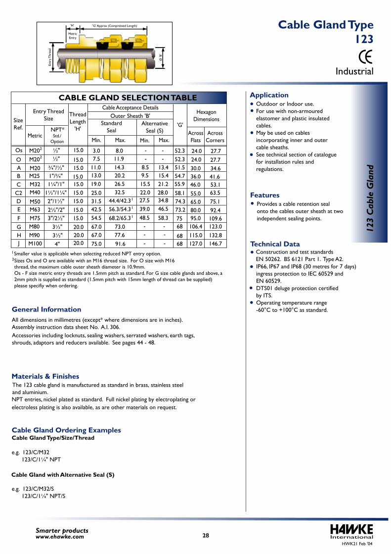
IP66, IP67 and IP68 (30 metres for 7 days) ingress protection to IEC 60529 and EN 60529. DTS01 deluge protection certified by ITS. Operating temperature range -60°C to +100°C as standard.
Construction and test standards EN 50262. BS 6121 Part 1. Type A2.
The 123 cable gland is manufactured as standard in brass, stainless steel
Outdoor or Indoor use. For use with non-armoured elastomer and plastic insulated cables. May be used on cables incorporating inner and outer cable sheaths. See technical section of catalogue for installation rules and regulations.
Provides a cable retention seal onto the cables outer sheath at two independent sealing points.
Cable Gland Ordering ExamplesCable Gland Type/Size/Thread e.g. 123/C/M32 123/C/1¼" NPT
Cable Gland with Alternative Seal (S)
e.g. 123/C/M32/S 123/C/1¼" NPT/S
All dimensions in millimetres (except* where dimensions are in inches).Assembly instruction data sheet No. A.I. 306. Accessories including locknuts, sealing washers, serrated washers, earth tags, shrouds, adaptors and reducers available. See pages 44 - 48.
2Smaller value is applicable when selecting reduced NPT entry option. 1
Sizes Os and O are available with an M16 thread size. For O size with M16 thread, the maximum cable outer sheath diameter is 10.9mm.Os - F size metric entry threads are 1.5mm pitch as standard. For G size cable glands and above, a 2mm pitch is supplied as standard (1.5mm pitch with 15mm length of thread can be supplied) please specifiy when ordering.
InternationalSmarter productswww.ehawke.com
CABLE GLAND SELECTION TABLE
SizeRef.
O
Os
ABCC2DE
F
M20M20M25M32M40
M50M63M75
¾"/½"
M20 ½"
2"/1½"2½"/2"3"/2½"
½"
1"/¾"1¼"/1"
1½"/1¼"
Entry ThreadSize
MetricNPT*Std./
Option
H J
M80M90M100
3½"3½"
4"
106.4115.0127.0
123.0132.8146.7
G
3.07.5
11.013.019.025.031.542.554.5
8.011.914.320.226.532.5
44.4/42.356.3/54.368.2/65.3
8.59.515.522.027.539.048.5
13.415.421.228.034.846.5
58.3
--
-- 24.0
30.036.046.0
55.065.080.095.0
27.734.641.653.163.575.192.4109.6
24.0 27.752.352.351.554.755.9
73.2
58.174.3
7568
6868
Min. Max.
'G'AcrossFlats
AcrossCorners
HexagonDimensions
Min. Max.
Outer Sheath 'B'Standard
SealAlternative
Seal (S)
67.067.075.0
73.077.691.6
- -
- -- -
2
2
1
1
1
ThreadLength
'H'
15.0
15.015.015.015.015.015.015.015.020.020.020.0
123
Cab
le G
land
Cable Acceptance Details
Industrial
123 Cable Gland Type
121
Technical Data
Features
Application
Materials & Finishes
General Information
HWK21 Feb '04
'H' 'G' Approx (Compressed Length)
Ø 'B
'
Entr
y Thr
ead
MetricEntry
28
electroless plating is also available, as are other materials on request.NPT entries, nickel plated as standard. Full nickel plating by electroplating or and aluminium.
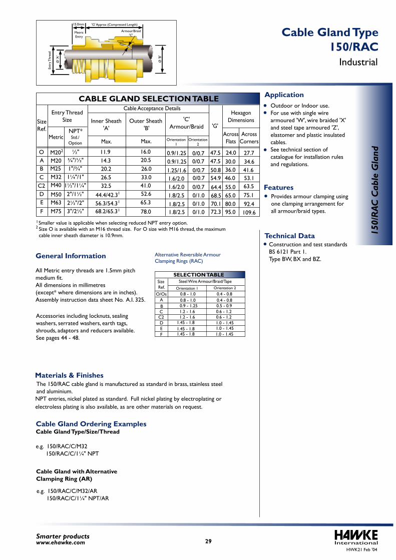
Construction and test standards BS 6121 Part 1.Type BW, BX and BZ.
The 150/RAC cable gland is manufactured as standard in brass, stainless steeland aluminium.
Outdoor or Indoor use. For use with single wire armoured 'W', wire braided 'X' and steel tape armoured 'Z', elastomer and plastic insulated cables.
See technical section of catalogue for installation rules and regulations.
Provides armour clamping using one clamping arrangement for all armour/braid types.
Cable Gland Ordering ExamplesCable Gland Type/Size/Thread e.g. 150/RAC/C/M32 150/RAC/C/1¼" NPT
All Metric entry threads are 1.5mm pitch medium fit.All dimensions in millimetres (except* where dimensions are in inches).Assembly instruction data sheet No. A.I. 325.
Accessories including locknuts, sealing washers, serrated washers, earth tags, shrouds, adaptors and reducers available. See pages 44 - 48.
Alternative Reversible Armour Clamping Rings (RAC)
0.8 - 1.0 0.4 - 0.80.8 - 1.0 0.4 - 0.80.9 - 1.25 0.5 - 0.91.2 - 1.6 0.6 - 1.21.2 - 1.6 0.6 - 1.2
1.45 - 1.8
1.0 - 1.45 1.0 - 1.45 1.0 - 1.45
1.45 - 1.8 1.45 - 1.8
SELECTION TABLE
AO/Os
BC
DEF
C2
Size Ref.
Steel Wire Armour/Braid/TapeOrientation 1 Orientation 2
Cable Gland with Alternative Clamping Ring (AR)
e.g. 150/RAC/C/M32/AR 150/RAC/C/1¼" NPT/AR
Smaller value is applicable when selecting reduced NPT entry option. 12 Size O is available with an M16 thread size. For O size with M16 thread, the maximum
cable inner sheath diameter is 10.9mm.
International29Smarter productswww.ehawke.com
CABLE GLAND SELECTION TABLE
SizeRef.
OABCC2DE
F
M20M20M25M32M40
M50M63M75
¾"/½"
2"/1½"2½"/2"3"/2½"
½"
1"/¾"1¼"/1"
1½"/1¼"
Entry ThreadSize
MetricNPT*
Outer Sheath 'B'
Cable Acceptance Details
Max.Max.Std./
OptionOrientation
2Orientation
1
'G'AcrossFlats
AcrossCorners
HexagonDimensions'C'
Armour/Braid
24.030.036.046.0
55.065.080.095.0
27.734.641.653.163.575.192.4109.6
47.547.550.854.9
64.468.570.172.3
16.020.526.033.041.052.665.3
78.0
0.9/1.250.9/1.251.25/1.61.6/2.01.6/2.01.8/2.51.8/2.51.8/2.5
0/0.70/0.7 0/0.70/0.70/0.70/1.00/1.00/1.0
Inner Sheath'A'
11.914.320.226.532.5
44.4/42.356.3/54.368.2/65.3
1
1
1
2
150/
RAC
Cab
le G
land
Industrial 150/RAC
Cable Gland Type
Technical Data
Features
Application
Materials & Finishes
General Information
HWK21 Feb '04
'G' Approx (Compressed Length)15.0mm
MetricEntry
Ø 'B
'
Ø 'A
'
Armour/Braid'C'
Entr
y Thr
ead
electroless plating is also available, as are other materials on request.NPT entries, nickel plated as standard. Full nickel plating by electroplating or
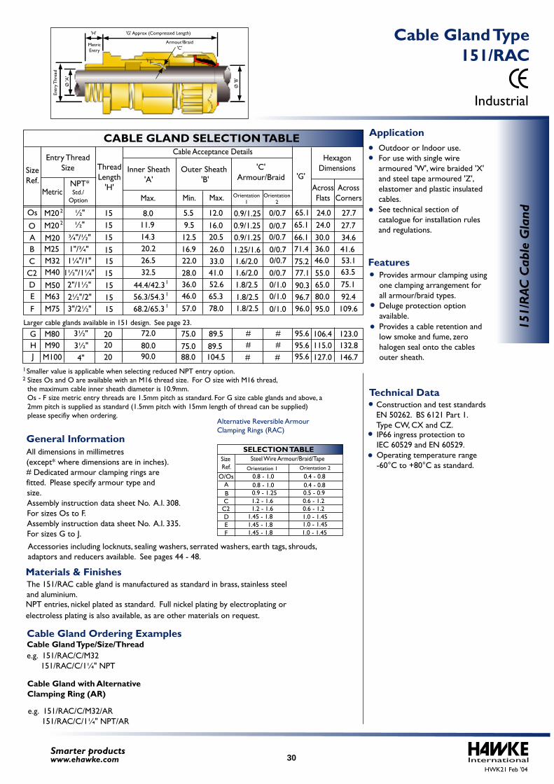
Larger cable glands available in 151 design. See page 23.
IP66 ingress protection to IEC 60529 and EN 60529. Operating temperature range -60°C to +80°C as standard.
Construction and test standards EN 50262. BS 6121 Part 1.Type CW, CX and CZ.
The 151/RAC cable gland is manufactured as standard in brass, stainless steeland aluminium.
All dimensions in millimetres (except* where dimensions are in inches).# Dedicated armour clamping rings are fitted. Please specify armour type and size.Assembly instruction data sheet No. A.I. 308. For sizes Os to F.Assembly instruction data sheet No. A.I. 335. For sizes G to J.
Accessories including locknuts, sealing washers, serrated washers, earth tags, shrouds, adaptors and reducers available. See pages 44 - 48.
0.8 - 1.0 0.4 - 0.80.8 - 1.0 0.4 - 0.80.9 - 1.25 0.5 - 0.91.2 - 1.6 0.6 - 1.21.2 - 1.6 0.6 - 1.2
1.45 - 1.8 1.0 - 1.45 1.0 - 1.45 1.0 - 1.45
1.45 - 1.8 1.45 - 1.8
SELECTION TABLE
AO/Os
BC
DEF
C2
Size Ref.
Steel Wire Armour/Braid/TapeOrientation 1 Orientation 2
Alternative Reversible Armour Clamping Rings (RAC)
Outdoor or Indoor use. For use with single wire armoured 'W', wire braided 'X' and steel tape armoured 'Z', elastomer and plastic insulated cables. See technical section of
catalogue for installation rules and regulations.
Provides armour clamping using one clamping arrangement for all armour/braid types. Deluge protection option available.
Provides a cable retention and low smoke and fume, zero halogen seal onto the cables outer sheath.
Cable Gland Ordering ExamplesCable Gland Type/Size/Thread e.g. 151/RAC/C/M32 151/RAC/C/1¼" NPT
Cable Gland with Alternative Clamping Ring (AR)
e.g. 151/RAC/C/M32/AR 151/RAC/C/1¼" NPT/AR
2Smaller value is applicable when selecting reduced NPT entry option. 1
Sizes Os and O are available with an M16 thread size. For O size with M16 thread, the maximum cable inner sheath diameter is 10.9mm.Os - F size metric entry threads are 1.5mm pitch as standard. For G size cable glands and above, a 2mm pitch is supplied as standard (1.5mm pitch with 15mm length of thread can be supplied) please specifiy when ordering.
InternationalSmarter productswww.ehawke.com
CABLE GLAND SELECTION TABLE
SizeRef.
O
Os
ABCC2DE
F
M20M20M25M32M40
M50M63M75
¾"/½"
M20 ½"
2"/1½"2½"/2"3"/2½"
½"
1"/¾"1¼"/1"
1½"/1¼"
Entry ThreadSize
MetricNPT*
Outer Sheath 'B'
Cable Acceptance Details
Min. Max.Max.Std./
OptionOrientation
2Orientation
1
'G'AcrossFlats
AcrossCorners
HexagonDimensions'C'
Armour/Braid
24.030.036.046.0
55.065.080.095.0
27.734.641.653.163.575.192.4109.6
24.0 27.765.165.1
66.171.475.277.190.396.796.0
95.695.695.6
9.512.516.922.028.036.046.057.0
16.05.5 12.0
20.526.033.041.052.665.378.0
0.9/1.250.9/1.251.25/1.61.6/2.01.6/2.01.8/2.51.8/2.51.8/2.5
0/0.70.9/1.25 0/0.7
0/0.7 0/0.70/0.70/0.70/1.00/1.00/1.0
H J
M80M90M100
3½"3½"
4"
106.4115.0127.0
123.0132.8146.7
G ###
###
Inner Sheath'A'
11.914.320.226.532.5
44.4/42.3
8.0
56.3/54.368.2/65.3
72.080.090.0
89.589.5104.5
75.075.088.0
2
2
1
1
1
ThreadLength
'H'
151/
RAC
Cab
le G
land15
1515151515151515
202020
Industrial
151/RAC Cable Gland Type
Technical Data
General Information
Features
Application
Materials & Finishes
HWK21 Feb '04
'G' Approx (Compressed Length)
MetricEntry
Ø 'B
'
Ø 'A
'
Armour/Braid'C'
Entr
y Thr
ead
'H'
30
electroless plating is also available, as are other materials on request.NPT entries, nickel plated as standard. Full nickel plating by electroplating or

Larger cable glands available in 153 design. See page 23.
IP66 and IP67 ingress protection to IEC 60529, EN 60529 and NEMA 4X. Operating temperature range -60°C to +80°C as standard.
Construction and test standards EN 50262. BS 6121 Part 1.Type E1W, E1X and E1Z.
The 153/RAC cable gland is manufactured as standard in brass, stainless steeland aluminium.
All dimensions in millimetres (except* where dimensions are in inches).# Dedicated armour clamping rings are fitted. Please specify armour type and size.Assembly instruction data sheet No. A.I. 322. For sizes Os to F.Assembly instruction data sheet No. A.I. 329. For sizes G to J.
Accessories including locknuts, sealing washers, serrated washers, earth tags, shrouds, adaptors and reducers available. See pages 44 - 48.
0.8 - 1.0 0.4 - 0.80.8 - 1.0 0.4 - 0.80.9 - 1.25 0.5 - 0.91.2 - 1.6 0.6 - 1.21.2 - 1.6 0.6 - 1.2
1.45 - 1.8 1.0 - 1.45 1.0 - 1.45 1.0 - 1.45
1.45 - 1.8 1.45 - 1.8
SELECTION TABLE
AO/Os
BC
DEF
C2
Size Ref.
Steel Wire Armour/Braid/TapeOrientation 1 Orientation 2
Alternative Reversible Armour Clamping Rings (RAC)
Outdoor or Indoor use. For use with single wire armoured 'W', wire braided 'X' and steel tape armoured 'Z', elastomer and plastic insulated cables. Suitable for use with cables that exhibit "Cold Flow" characteristics.
See technical section of catalogue for installation rules and regulations.
Provides armour clamping using one clamping arrangement for all armour/braid types. Provides a diaphragm seal on the cables inner sheath. A diaphragm seal will not damage cable that that has "Cold Flow" characteristics. Deluge protection option available.
Provides a cable retention and low smoke and fume, zero halogen seal onto the cables outer sheath.
Cable Gland Ordering ExamplesCable Gland Type/Size/Thread e.g. 153/RAC/C/M32 153/RAC/C/1¼" NPT
Cable Gland with Alternative Clamping Ring (AR)
e.g. 153/RAC/C/M32/AR 153/RAC/C/1¼" NPT/AR
Smaller value is applicable when selecting reduced NPT entry option. 1
2 Sizes Os and O are available with an M16 thread size. For O size with M16 thread, the maximum cable inner sheath diameter is 10.9mm.Os - F size metric entry threads are 1.5mm pitch as standard. For G size cable glands and above, a 2mm pitch is supplied as standard (1.5mm pitch with 15mm length of thread can be supplied) please specifiy when ordering.
15
1515151515151515
202020
InternationalSmarter productswww.ehawke.com
CABLE GLAND SELECTION TABLE
SizeRef.
O
Os
ABCC2DE
F
M20M20M25M32M40
M50M63M75
¾"/½"
M20 ½"
2"/1½"2½"/2"3"/2½"
½"
1"/¾"1¼"/1"
1½"/1¼"
Entry ThreadSize
MetricNPT*
Outer Sheath 'B'
Cable Acceptance Details
Min.Min. Max.Max.Std./
OptionOrientation
2Orientation
1
'G'AcrossFlats
AcrossCorners
HexagonDimensions'C'
Armour/Braid
24.030.036.046.0
55.065.080.095.0
27.734.641.653.163.575.192.4109.6
24.0 27.765.165.1
66.171.475.277.190.396.796.0
95.695.695.6
9.512.516.922.028.036.046.057.0
16.05.5 12.0
20.526.033.041.052.665.378.0
0.9/1.250.9/1.251.25/1.61.6/2.01.6/2.01.8/2.51.8/2.51.8/2.5
0/0.70.9/1.25 0/0.7
0/0.7 0/0.70/0.70/0.70/1.00/1.00/1.0
H J
M80M90M100
3½"3½"
4"
106.4115.0127.0
123.0132.8146.7
G ###
###
Inner Sheath'A'
11.914.220.126.432.4
44.5/42.3
8.0
54.066.0/65.3
73.077.691.6
89.589.5104.5
75.075.088.0
4.07.5
11.513.719.626.030.041.553.0
67.067.075.0
1
1
2
2
ThreadLength
'H'
153/
RAC
Cab
le G
land
Industrial
153/RAC Cable Gland Type
Technical Data
General Information
Features
Application
Materials & Finishes
HWK21 Feb '04
'G' Approx (Compressed Length)'H'
MetricEntry
Ø 'B
'
Ø 'A
'
Armour/Braid'C'
Entr
y Thr
ead
DiaphragmSeal
31
electroless plating is also available, as are other materials on request.NPT entries, nickel plated as standard. Full nickel plating by electroplating or
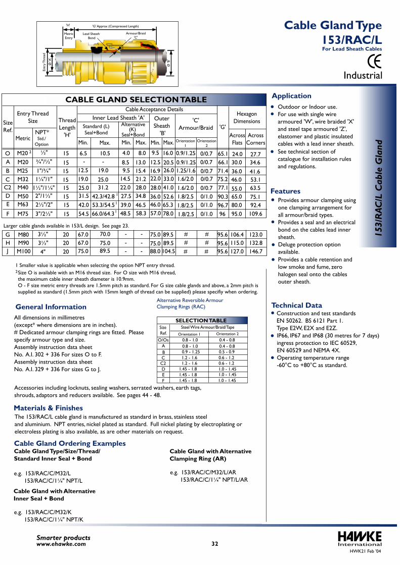
Larger cable glands available in 153/L design. See page 23.
IP66, IP67 and IP68 (30 metres for 7 days) ingress protection to IEC 60529, EN 60529 and NEMA 4X. Operating temperature range -60°C to +80°C as standard.
Construction and test standardsEN 50262. BS 6121 Part 1.Type E2W, E2X and E2Z.
The 153/RAC/L cable gland is manufactured as standard in brass, stainless steeland aluminium. NPT entries, nickel plated as standard. Full nickel plating by electroplating or
All dimensions in millimetres(except* where dimensions are in inches).# Dedicated armour clamping rings are fitted. Please specify armour type and size.Assembly instruction data sheet No. A.I. 302 + 336 For sizes O to F.Assembly instruction data sheet No. A.I. 329 + 336 For sizes G to J.
Accessories including locknuts, sealing washers, serrated washers, earth tags,shrouds, adaptors and reducers available. See pages 44 - 48.
0.8 - 1.0 0.4 - 0.80.8 - 1.0 0.4 - 0.80.9 - 1.25 0.5 - 0.91.2 - 1.6 0.6 - 1.21.2 - 1.6 0.6 - 1.2
1.45 - 1.8 1.0 - 1.45 1.0 - 1.45 1.0 - 1.45
1.45 - 1.8 1.45 - 1.8
SELECTION TABLE
AO/Os
BC
DEF
C2
SizeRef.
Steel Wire Armour/Braid/TapeOrientation 1 Orientation 2
Alternative Reversible ArmourClamping Rings (RAC)
Alternative
Min. Max.
Size O is available with an M16 thread size. For O size with M16 thread, the maximum cable inner sheath diameter is 10.9mm. O - F size metric entry threads are 1.5mm pitch as standard. For G size cable glands and above, a 2mm pitch is supplied as standard (1.5mm pitch with 15mm length of thread can be supplied) please specifiy when ordering.
Outdoor or Indoor use. For use with single wire armoured 'W', wire braided 'X' and steel tape armoured 'Z', elastomer and plastic insulated cables with a lead inner sheath.
See technical section of catalogue for installation rules and regulations.
Provides armour clamping using one clamping arrangement for all armour/braid types. Provides a seal and an electrical bond on the cables lead inner sheath. Deluge protection option available.
Provides a cable retention and low smoke and fume, zerohalogen seal onto the cables outer sheath.
Seal+Bond(K)
2
InternationalSmarter productswww.ehawke.com
CABLE GLAND SELECTION TABLE
SizeRef.
OABCC2DE
F
M20M20M25M32M40M50M63
M75
¾"/½"
2"/1½"2½"/2"
3"/2½"
½"
1"/¾"1¼"/1"
1½"/1¼"
Entry ThreadSize
MetricNPT*
OuterSheath
'B'
Cable Acceptance Details
Min. Max.Max.Std./
OptionOrientation
2Orientation
1
'G'AcrossFlats
AcrossCorners
HexagonDimensions'C'
Armour/Braid
24.030.036.046.0
55.065.080.095.0
27.734.6
41.653.163.575.192.4109.6
65.166.171.4
77.190.3
9.5
12.516.922.0
28.036.046.057.0
16.0
Min.
20.526.033.041.052.665.378.0
0.9/1.25
0.9/1.251.25/1.61.6/2.01.6/2.01.8/2.51.8/2.51.8/2.5
0/0.70/0.70/0.70/0.70/0.70/1.00/1.00/1.0
75.2
96.796
HJ
M80M90M100
3½"3½"
4"
106.4115.0127.0
123.0132.8146.7
G 89.589.5104.5
95.695.695.6
###
###
Inner Lead Sheath 'A'Standard (L)Seal+Bond
67.067.075.0
70.075.089.5
75.075.088.0
-
-- -- -
-
-4.0 8.06.5
12.519.025.031.542.054.5
10.5
19.0
25.031.2
42.3/42.853.3/54.566.0/64.3
9.514.522.027.539.048.5
15.48.5 13.0
21.228.034.8
46.558.3
2
ThreadLength
'H'
15
15151515151515
202020
AR/351
C/L
dnalG
elbaC
Industrial
153/RAC/L Cable Gland Type
For Lead Sheath Cables
Technical DataGeneral Information
Features
Application
Materials & Finishes
Cable Gland Ordering ExamplesCable Gland Type/Size/Thread/Standard Inner Seal + Bond
e.g. 153/RAC/C/M32/L 153/RAC/C/1¼" NPT/L
Cable Gland with AlternativeInner Seal + Bond
e.g. 153/RAC/C/M32/K 153/RAC/C/1¼" NPT/K
Cable Gland with AlternativeClamping Ring (AR)
e.g. 153/RAC/C/M32/L/AR 153/RAC/C/1¼" NPT/L/AR
HWK21 Feb '04
Armour/Braid'C'
'B'Ø
'A'
Ø
Entr
yThr
dae
MetricEntry
Lead Sheath Bond
'H' 'G' Approx (Compressed Length)
electroless plating is also available, as are other materials on request.
1
1
1
1 Smaller value is applicable when selecting the option NPT entry thread.
32
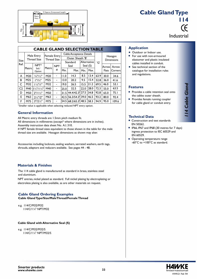
IP66, IP67 and IP68 (30 metres for 7 days) ingress protection to IEC 60529 and EN 60529. Operating temperature range -60°C to +100°C as standard.
Construction and test standards EN 50262.
The 114 cable gland is manufactured as standard in brass, stainless steeland aluminium.
All Metric entry threads are 1.5mm pitch medium fit.All dimensions in millimetres (except* where dimensions are in inches).Assembly instruction data sheet No. A.I. 310.# NPT female thread sizes equivalent to those shown in the table for the male thread size are available. Hexagon dimensions as shown may alter.
Accessories including locknuts, sealing washers, serrated washers, earth tags, shrouds, adaptors and reducers available. See pages 44 - 48.
Outdoor or Indoor use. For use with non-armoured elastomer and plastic insulated cables installed in conduit. See technical section of the catalogue for installation rules and regulations.
Provides a cable retention seal onto the cables outer sheath. Provides female running coupler for cable gland or conduit entry.
Cable Gland Ordering ExamplesCable Gland Type/Size/MaleThread/Female Thread
e.g. 114/C/M32/M32 114/C/1¼" NPT/M32
e.g. 114/C/M32/M32/S 114/C/1¼" NPT/M32/S
Cable Gland with Alternative Seal (S)
--
-
--
--
Smaller value is applicable when selecting reduced NPT entry option. 1
International33Smarter productswww.ehawke.com
CABLE GLAND SELECTION TABLE
SizeRef.
ABCC2DE
F
M20M25M32M40M50M63M75
M20M25M32M40M50M63M75
¾"/½"
2"/1½"2½"/2"3"/2½"
1"/¾"1¼"/1"
1½"/1¼"
Male EntryThread Size
MetricNPT*
Cable Acceptance Details
Min. Max.Std./
Option
Female EntryThread Size
MetricNPT
#
'G'AcrossFlats
AcrossCorners
HexagonDimensions
30.036.046.0
55.065.080.095.0
34.641.653.163.575.192.4109.6
11.013.019.025.031.542.554.5
14.320.226.532.5
44.4/42.356.3/54.368.2/65.3
8.59.5
15.522.027.539.048.5
13.415.421.228.034.846.558.3
63.952.869.572.392.893.294.9
Min. Max.
Outer Sheath 'B'Standard
SealAlternative
Seal (S)
1
1
1
114
Cab
le G
land
Industrial
114 Cable Gland Type
Technical DataGeneral Information
Features
Application
Materials & Finishes
HWK21 Feb '04
'G' Approx (Compressed Length)15.0mm
MetricEntry
Ø 'B
'
Fem
ale
Entr
y Thr
ead
Mal
e En
try T
hrea
d
electroless plating is also available, as are other materials on request.NPT entries, nickel plated as standard. Full nickel plating by electroplating or

InternationalHWK21 Feb '04
Flameproof/Increased Safety and Industrial
34Smarter productswww.ehawke.com
Haw
ke C
able
Gla
nds
Hawke Cable Glands
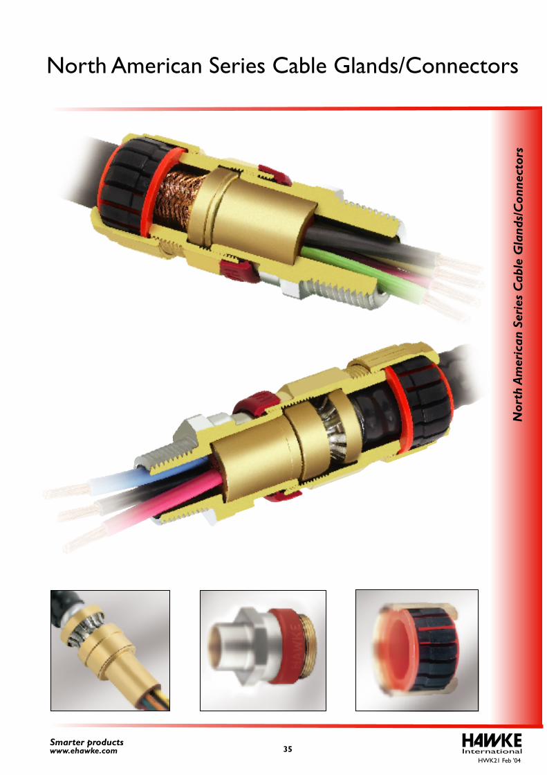
InternationalHWK21 Feb '04
35Smarter productswww.ehawke.com
Nor
th A
mer
ican
Ser
ies
Cab
le G
land
s/C
onne
ctor
s
North American Series Cable Glands/Connectors
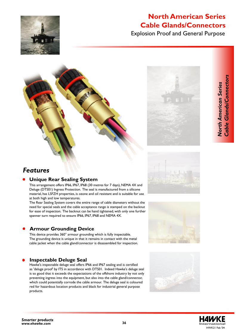
InternationalHWK21 Feb '04
Unique Rear Sealing System This arrangement offers IP66, IP67, IP68 (30 metres for 7 days), NEMA 4X and Deluge (DTS01) Ingress Protection. The seal is manufactured from a silicone material, has LSFZH properties, is ozone and oil resistant and is suitable for use at both high and low temperatures. The Rear Sealing System covers the entire range of cable diameters without theneed for special seals and the cable acceptance range is stamped on the backnut for ease of inspection. The backnut can be hand tightened, with only one further spanner turn required to ensure IP66, IP67, IP68 and NEMA 4X.
Inspectable Deluge SealHawke's inspectable deluge seal offers IP66 and IP67 sealing and is certifiedas 'deluge proof' by ITS in accordance with DTS01. Indeed Hawke's deluge seal is so good that it exceeds the expectations of the offshore industry by not only preventing ingress into the equipment, but also into the cable gland/connector, which could potentially corrode the cable armour. The deluge seal is coloured red for hazardous location products and black for industrial general purpose products.
36Smarter productswww.ehawke.com
Nor
th A
mer
ican
Ser
ies
Cab
le G
land
s/C
onne
ctor
s
Explosion Proof and General PurposeCable Glands/Connectors
North American Series
Features
Armour Grounding DeviceThis device provides 360° armour grounding which is fully inspectable.The grounding device is unique in that it remains in contact with the metal cable jacket when the cable gland/connector is disassembled for inspection.
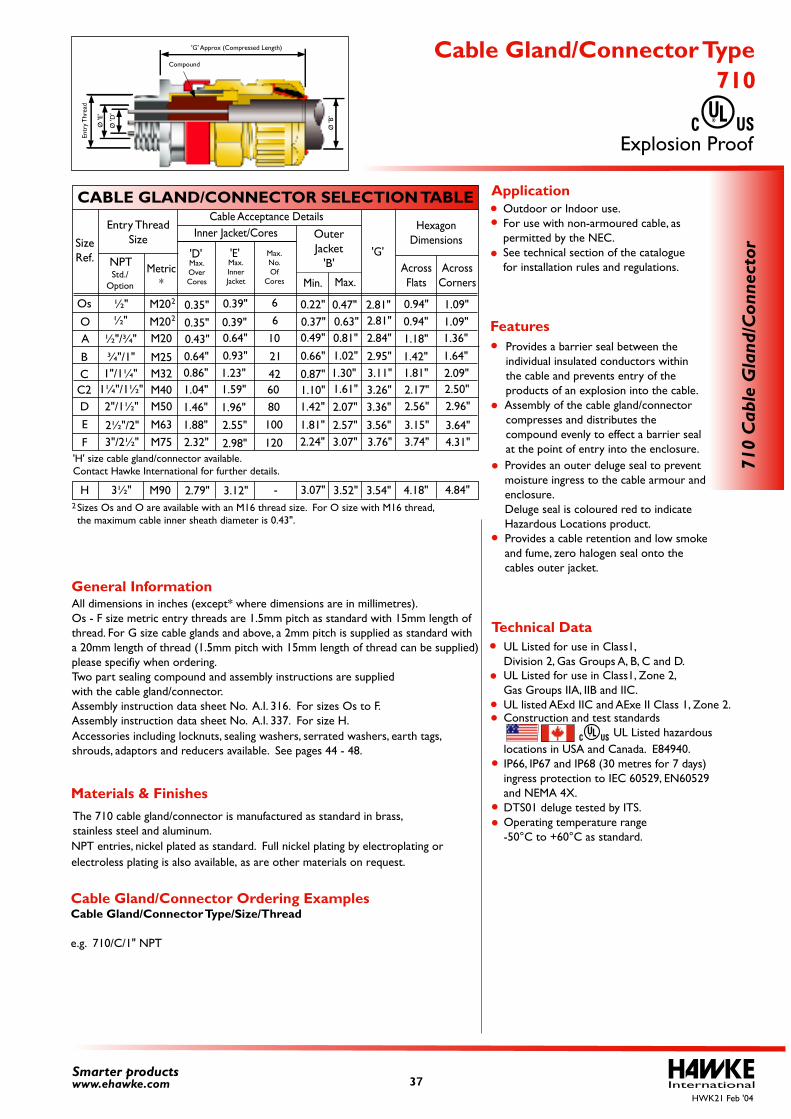
The 710 cable gland/connector is manufactured as standard in brass, stainless steel and aluminum.
All dimensions in inches (except* where dimensions are in millimetres).Os - F size metric entry threads are 1.5mm pitch as standard with 15mm length of thread. For G size cable glands and above, a 2mm pitch is supplied as standard with a 20mm length of thread (1.5mm pitch with 15mm length of thread can be supplied) please specifiy when ordering. Two part sealing compound and assembly instructions are supplied with the cable gland/connector.Assembly instruction data sheet No. A.I. 316. For sizes Os to F.Assembly instruction data sheet No. A.I. 337. For size H. Accessories including locknuts, sealing washers, serrated washers, earth tags, shrouds, adaptors and reducers available. See pages 44 - 48.
Outdoor or Indoor use. For use with non-armoured cable, as permitted by the NEC. See technical section of the catalogue for installation rules and regulations.
Cable Gland/Connector Ordering ExamplesCable Gland/Connector Type/Size/Thread
e.g. 710/C/1" NPT
UL Listed for use in Class1, Division 2, Gas Groups A, B, C and D.
locations in USA and Canada. E84940. IP66, IP67 and IP68 (30 metres for 7 days) ingress protection to IEC 60529, EN60529 and NEMA 4X. DTS01 deluge tested by ITS. Operating temperature range -50°C to +60°C as standard.
Construction and test standards UL Listed hazardous
UL Listed for use in Class1, Zone 2, Gas Groups IIA, IIB and IIC. UL listed AExd IIC and AExe II Class 1, Zone 2.
Sizes Os and O are available with an M16 thread size. For O size with M16 thread, the maximum cable inner sheath diameter is 0.43".
Provides an outer deluge seal to prevent moisture ingress to the cable armour and enclosure.Deluge seal is coloured red to indicate Hazardous Locations product.Provides a cable retention and low smoke and fume, zero halogen seal onto the cables outer jacket.
Provides a barrier seal between the individual insulated conductors within the cable and prevents entry of the products of an explosion into the cable. Assembly of the cable gland/connector compresses and distributes the compound evenly to effect a barrier seal at the point of entry into the enclosure.
InternationalSmarter productswww.ehawke.com
CABLE GLAND/CONNECTOR SELECTION TABLE
SizeRef.
A
BCC2DE
F
M20
M25M32M40M50
M63M75
½"/¾"
2"/1½"
2½"/2"3"/2½"
¾"/1"1"/1¼"
1¼"/1½"
Entry ThreadSize
Metric*
NPT
Cable Acceptance DetailsInner Jacket/Cores
Min. Max.Std./
Option
'G'AcrossFlats
AcrossCorners
HexagonDimensionsOuter
Jacket'B'Max.
OverCores
Max.No.Of
Cores
'D'Max.InnerJacket
'E'
2.79" 3.07"3.12" 3.52" 4.18"3.54" 4.84"-
2
2
710
Cab
le G
land
/Con
nect
or
Explosion Proof
710 Cable Gland/Connector Type
2
Technical Data
General Information
Features
Application
Materials & Finishes
HWK21 Feb '04
0.49"
0.66"
0.87"1.10"1.42"
1.81"2.24"
0.81"1.02"1.30"1.61"
2.07"
2.57"3.07"
2.84"
2.95"3.11"3.26"3.36"
3.56"3.76"
0.43"0.64"0.86"1.04"1.46"1.88"2.32"
0.64"0.93"1.23"1.59"
1.96"2.55"
2.98"
1.18"1.42"1.81"2.17"2.56"
3.15"3.74"
1.36"1.64"2.09"2.50"2.96"
3.64"4.31"
3½"H M90
'H' size cable gland/connector available. Contact Hawke International for further details.
10
21426080100
120
Ø 'E
'
Ø 'D
'
Entr
y Thr
ead
'G' Approx (Compressed Length)
Compound
Ø 'B
'
Os
O½"½"
0.22"0.37"
0.39" 660.39"
0.47"0.63"
2.81"2.81"
0.94"0.94"
1.09"1.09"
0.35"0.35"
M20M20
37
electroless plating is also available, as are other materials on request.NPT entries, nickel plated as standard. Full nickel plating by electroplating or
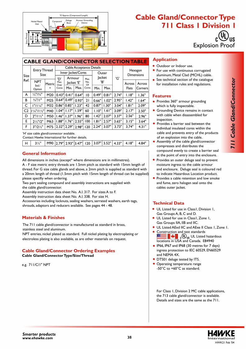
All dimensions in inches (except* where dimensions are in millimetres).A - F size metric entry threads are 1.5mm pitch as standard with 15mm length of thread. For G size cable glands and above, a 2mm pitch is supplied as standard with a 20mm length of thread (1.5mm pitch with 15mm length of thread can be supplied) please specifiy when ordering. Two part sealing compound and assembly instructions are supplied withthe cable gland/connector.Assembly instruction data sheet No. A.I. 317. For sizes A to F.Assembly instruction data sheet No. A.I. 338. For size H. Accessories including locknuts, sealing washers, serrated washers, earth tags, shrouds, adaptors and reducers available. See pages 44 - 48.
Outdoor or Indoor use. For use with continuous corrugated aluminum, Metal Clad (MCHL) cable. See technical section of the catalogue for installation rules and regulations.
Provides 360° armour grounding which is fully inspectable. Grounding Device remains in contact with cable when disassembled for inspection.
Cable Gland/Connector Ordering ExamplesCable Gland/Connector Type/Size/Thread
e.g. 711/C/1" NPT
Provides an outer deluge seal to prevent moisture ingress to the cable armour and enclosure. Deluge seal is coloured red to indicate Hazardous Location product.Provides a cable retention and low smoke and fume, zero halogen seal onto the cables outer jacket.
UL Listed for use in Class1, Division 1, Gas Groups A, B, C and D. UL Listed AExd IIC and AExe II Class 1, Zone 1.
IP66, IP67 and IP68 (30 metres for 7 days) ingress protection to IEC 60529, EN60529 and NEMA 4X. DTS01 deluge tested by ITS. Operating temperature range -50°C to +60°C as standard.
Construction and test standards UL Listed hazardouslocations in USA and Canada. E84940
For Class 1, Division 2 MC cable applications,the 713 cable gland/connector is available.Details and sizes are the same as the 711.
UL Listed for use in Class1, Zone 1, Gas Groups IIA, IIB and IIC.
Assembly of the cable gland/connector compresses and distributes the compound evenly to create a barrier seal at the point of entry into the enclosure.
Provides a barrier seal between the individual insulated cores within the cable and prevents entry of the products of an explosion into the cable.
InternationalSmarter productswww.ehawke.com
CABLE GLAND/CONNECTOR SELECTION TABLE
SizeRef.
ABCC2DE
F
M20M25M32M40M50M63M75
Entry ThreadSize
Metric*
NPT
Cable Acceptance DetailsInner Jacket/Cores
Min.Min. Max.Std./
Option
'G'AcrossFlats
AcrossCorners
HexagonDimensions
Max.
Armour Jacket 'E'
OuterJacket
'B'Max.OverCores
Max.No.Of
Cores
'D'
3.47"2.93"2.79" 3.07" 3.52" 4.18"4.33" 4.84"120
½"/¾"
¾"/1"
1"/1¼"1¼"/1½"
The 711 cable gland/connector is manufactured as standard in brass, stainless steel and aluminum.
Materials & Finishes
711
Cab
le G
land
/Con
nect
or
Explosion Proof
711 Class 1 Division 1 Cable Gland/Connector Type
Technical Data
General Information
Features
Application
HWK21 Feb '04
0.49"
0.66"0.87"1.10"1.42"1.81"2.24"
0.81"1.02"1.30"1.61"
2.07"2.57"3.07"
2.74"2.95"3.04"3.09"3.37"3.65"3.73"
0.43"0.64"0.86"1.04"1.46"1.88"2.32"
0.41"0.49"0.85"1.17"1.37"1.76"2.29"
0.64"0.93"1.23"1.59"
1.96"2.55"
2.98"
1.18"1.42"1.81"2.17"2.56"3.15"3.74"
1.36"1.64"2.09"2.50"2.96"3.64"4.31"
3½"H M90
'H' size cable gland/connector available.Contact Hawke International for further details.
Entr
y Thr
ead
'G' Approx (Compressed Length)
Compound
Ø 'B
'
DelugeBoot
Armour GroundingDevice
Nickel Plated Hub
Ø 'E
'
Ø 'D
'
1021426080100
120
2"/1½"2½"/2"3"/2½"
38
electroless plating is also available, as are other materials on request.NPT entries, nickel plated as standard. Full nickel plating by electroplating or
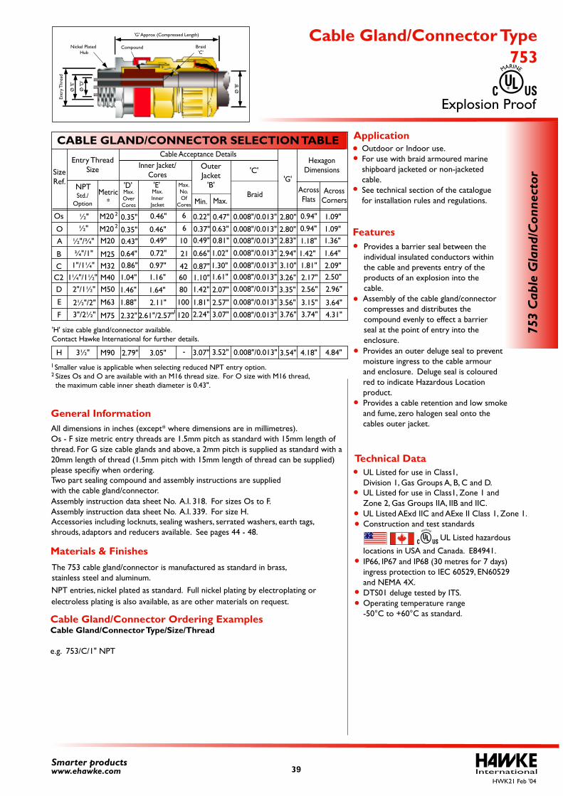
All dimensions in inches (except* where dimensions are in millimetres).Os - F size metric entry threads are 1.5mm pitch as standard with 15mm length of thread. For G size cable glands and above, a 2mm pitch is supplied as standard with a 20mm length of thread (1.5mm pitch with 15mm length of thread can be supplied) please specifiy when ordering.
Assembly instruction data sheet No. A.I. 318. For sizes Os to F.Assembly instruction data sheet No. A.I. 339. For size H. Accessories including locknuts, sealing washers, serrated washers, earth tags, shrouds, adaptors and reducers available. See pages 44 - 48.
Outdoor or Indoor use. For use with braid armoured marine shipboard jacketed or non-jacketed cable. See technical section of the catalogue for installation rules and regulations.
Cable Gland/Connector Ordering ExamplesCable Gland/Connector Type/Size/Thread
e.g. 753/C/1" NPT
UL Listed for use in Class1, Division 1, Gas Groups A, B, C and D.
Construction and test standards
UL Listed for use in Class1, Zone 1 and Zone 2, Gas Groups IIA, IIB and IIC. UL Listed AExd IIC and AExe II Class 1, Zone 1.
Two part sealing compound and assembly instructions are supplied with the cable gland/connector.
Sizes Os and O are available with an M16 thread size. For O size with M16 thread, the maximum cable inner sheath diameter is 0.43".
Provides an outer deluge seal to prevent moisture ingress to the cable armour and enclosure. Deluge seal is coloured red to indicate Hazardous Location product.Provides a cable retention and low smoke and fume, zero halogen seal onto the cables outer jacket.
Provides a barrier seal between the individual insulated conductors within the cable and prevents entry of the products of an explosion into the cable. Assembly of the cable gland/connector compresses and distributes the compound evenly to effect a barrier seal at the point of entry into the enclosure.
IP66, IP67 and IP68 (30 metres for 7 days) ingress protection to IEC 60529, EN60529 and NEMA 4X. DTS01 deluge tested by ITS. Operating temperature range -50°C to +60°C as standard.
UL Listed hazardous
locations in USA and Canada. E84941.
2
InternationalSmarter productswww.ehawke.com
CABLE GLAND/CONNECTOR SELECTION TABLE
SizeRef.
A
B
CC2D
E
F
M20
M25M32M40M50
M63
M75
Entry ThreadSize
Metric*
Cable Acceptance DetailsInner Jacket/
Cores
Min. Max.
'G'AcrossFlats
AcrossCorners
HexagonDimensionsOuter
Jacket'B'
Max.OverCores
Max.No.Of
Cores
'D'Max.InnerJacket
'E'
2.79" 3.07"3.05" 3.52" 4.18"3.54" 4.84"-
½"/¾"
¾"/1"1"/1¼"
1¼"/1½"
½"½"
NPTStd./
Option
2"/1½"
2½"/2"3"/2½"
0.008"/0.013"
0.008"/0.013"0.008"/0.013"
0.008"/0.013"
0.008"/0.013"0.008"/0.013"0.008"/0.013"
0.008"/0.013"
0.008"/0.013"
0.008"/0.013"
'C'
Braid
2
2
1
The 753 cable gland/connector is manufactured as standard in brass, stainless steel and aluminum.
Materials & Finishes
753
Cab
le G
land
/Con
nect
or
Explosion Proof
753 Cable Gland/Connector Type
MARINE
MARINE
Technical Data
General Information
Features
Application
HWK21 Feb '04
0.49"
0.66"
0.87"1.10"1.42"
1.81"2.24"
0.81"
1.02"
1.30"1.61"
2.07"
2.57"3.07"
2.83"
2.94"3.10"3.26"
3.35"
3.56"3.76"
0.43"
0.64"0.86"1.04"
1.46"
1.88"
2.32"
0.49"
0.72"
0.97"1.16"
1.64"
2.11"
2.61"/2.57"
1.18"
1.42"1.81"2.17"2.56"
3.15"3.74"
1.36"
1.64"
2.09"2.50"
2.96"
3.64"4.31"
3½"H M90
'H' size cable gland/connector available. Contact Hawke International for further details.
10
21
4260
80
100
120
Os
O
0.22"
0.37"
0.46" 6
60.46"
0.47"0.63"
2.80"
2.80"
0.94"
0.94"1.09"
1.09"0.35"
0.35"
M20
M20
Ø 'E
'
Entr
y Thr
ead
'G' Approx (Compressed Length)
Compound
Ø 'B
'
Nickel Plated Hub
Ø 'D
'
Braid'C'
Smaller value is applicable when selecting reduced NPT entry option. 1
39
electroless plating is also available, as are other materials on request.NPT entries, nickel plated as standard. Full nickel plating by electroplating or
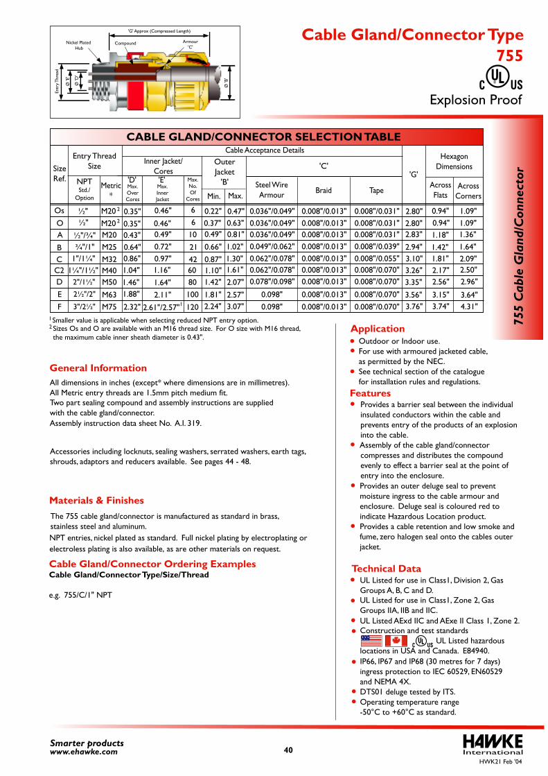
All dimensions in inches (except* where dimensions are in millimetres).All Metric entry threads are 1.5mm pitch medium fit.
Assembly instruction data sheet No. A.I. 319.
Accessories including locknuts, sealing washers, serrated washers, earth tags, shrouds, adaptors and reducers available. See pages 44 - 48.
Cable Gland/Connector Ordering ExamplesCable Gland/Connector Type/Size/Thread
e.g. 755/C/1" NPT
Two part sealing compound and assembly instructions are supplied with the cable gland/connector.
Sizes Os and O are available with an M16 thread size. For O size with M16 thread, the maximum cable inner sheath diameter is 0.43".
Smaller value is applicable when selecting reduced NPT entry option. 1
2
International40Smarter productswww.ehawke.com
CABLE GLAND/CONNECTOR SELECTION TABLE
SizeRef.
A
BCC2DE
F
Entry ThreadSize
Cable Acceptance DetailsInner Jacket/
Cores
Min. Max.
'G'AcrossFlats
AcrossCorners
HexagonDimensionsOuter
Jacket'B'
0.008"/0.013"0.008"/0.013"0.008"/0.013"0.008"/0.013"0.008"/0.013"0.008"/0.013"0.008"/0.013"
0.008"/0.013"0.008"/0.013"
'C'
Braid
0.036"/0.049"0.036"/0.049"0.036"/0.049"0.049"/0.062"0.062"/0.078"0.062"/0.078"0.078"/0.098"
0.098" 0.098"
Steel WireArmour
0.008"/0.031"0.008"/0.031"0.008"/0.031"0.008"/0.039"0.008"/0.055"0.008"/0.070"0.008"/0.070"
0.008"/0.070"0.008"/0.070"
TapeMax.
OverCores
Max.No.Of
Cores
'D'Max.InnerJacket
'E'Metric
*
M20M25M32M40M50
M63M75
M20M20
NPTStd./
Option
½"/¾"¾"/1"
1"/1¼"1¼"/1½"
½"½"
2
2
1
755
Cab
le G
land
/Con
nect
or
Outdoor or Indoor use. For use with armoured jacketed cable, as permitted by the NEC. See technical section of the catalogue for installation rules and regulations.
UL Listed for use in Class1, Division 2, Gas Groups A, B, C and D. UL Listed AExd IIC and AExe II Class 1, Zone 2.
IP66, IP67 and IP68 (30 metres for 7 days) ingress protection to IEC 60529, EN60529 and NEMA 4X. DTS01 deluge tested by ITS. Operating temperature range -50°C to +60°C as standard.
Construction and test standards UL Listed hazardouslocations in USA and Canada. E84940.
UL Listed for use in Class1, Zone 2, Gas Groups IIA, IIB and IIC.
Provides an outer deluge seal to prevent moisture ingress to the cable armour and enclosure. Deluge seal is coloured red to indicate Hazardous Location product.Provides a cable retention and low smoke and fume, zero halogen seal onto the cables outer jacket.
Provides a barrier seal between the individual insulated conductors within the cable and prevents entry of the products of an explosion into the cable. Assembly of the cable gland/connector compresses and distributes the compound evenly to effect a barrier seal at the point of entry into the enclosure.
Technical Data
Features
Application
Explosion Proof
755 Cable Gland/Connector Type
General Information
Materials & FinishesThe 755 cable gland/connector is manufactured as standard in brass, stainless steel and aluminum.
HWK21 Feb '04
0.49"
0.66"
0.87"1.10"1.42"
1.81"2.24"
0.81"1.02"1.30"1.61"
2.07"
2.57"3.07"
2.83"
2.94"3.10"3.26"3.35"
3.56"3.76"
0.43"0.64"0.86"1.04"1.46"1.88"
2.32"
0.49"0.72" 0.97"1.16"
1.64"2.11"
2.61"/2.57"
1.18"1.42"1.81"2.17"2.56"
3.15"3.74"
1.36"1.64"2.09"2.50"2.96"
3.64"4.31"
10
21426080100
120
Os
O0.22"0.37"
0.46" 660.46"
0.47"0.63"
2.80"2.80"
0.94"0.94"
1.09"1.09"
0.35"0.35"
Ø 'E
'
Entr
y Thr
ead
'G' Approx (Compressed Length)
Compound
Ø 'B
'
Nickel Plated Hub
Ø 'D
'
Armour'C'
2"/1½"
2½"/2"
3"/2½"
electroless plating is also available, as are other materials on request.NPT entries, nickel plated as standard. Full nickel plating by electroplating or
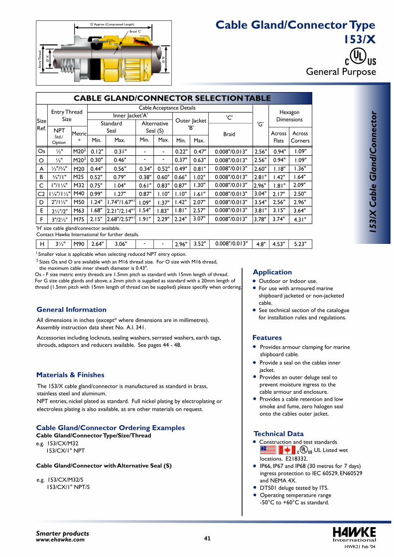
'H' size cable gland/connector available. Contact Hawke International for further details.
e.g. 153/CX/M32/S 153/CX/1" NPT/S
Cable Gland/Connector with Alternative Seal (S)
Cable Gland/Connector Ordering ExamplesCable Gland/Connector Type/Size/Thread e.g. 153/CX/M32 153/CX/1" NPT
All dimensions in inches (except* where dimensions are in millimetres).Assembly instruction data sheet No. A.I. 341.
Accessories including locknuts, sealing washers, serrated washers, earth tags, shrouds, adaptors and reducers available. See pages 44 - 48.
Sizes Os and O are available with an M16 thread size. For O size with M16 thread, the maximum cable inner sheath diameter is 0.43".Os - F size metric entry threads are 1.5mm pitch as standard with 15mm length of thread. For G size cable glands and above, a 2mm pitch is supplied as standard with a 20mm length of thread (1.5mm pitch with 15mm length of thread can be supplied) please specifiy when ordering.
Outdoor or Indoor use. For use with armoured marine shipboard jacketed or non-jacketed cable. See technical section of the catalogue for installation rules and regulations.
Provide a seal on the cables inner jacket.Provides an outer deluge seal to prevent moisture ingress to thecable armour and enclosure. Provides a cable retention and low smoke and fume, zero halogen seal onto the cables outer jacket.
Provides armour clamping for marine shipboard cable.
locations. E218332. IP66, IP67 and IP68 (30 metres for 7 days) ingress protection to IEC 60529, EN60529 and NEMA 4X. DTS01 deluge tested by ITS. Operating temperature range -50°C to +60°C as standard.
Construction and test standards UL Listed wet
Smaller value is applicable when selecting reduced NPT entry option. 1
2
InternationalSmarter productswww.ehawke.com
CABLE GLAND/CONNECTOR SELECTION TABLE
SizeRef.
O
Os
ABCC2DE
F
M20M20M25M32M40M50M63M75
M20
Entry ThreadSize
Metric*
Cable Acceptance Details
'G'
AcrossFlats
AcrossCorners
HexagonDimensions
StandardSeal
AlternativeSeal (S)
Inner Jacket'A'
Max.Min. Max.Min.
½"/¾"¾"/1"
1"/1¼"1¼"/1½"
NPTStd./
Option
½"½"
- -- -0.30"
0.44"0.52"0.75"0.99"1.24"1.68"2.15"
0.12"0.46"0.56"0.79"1.04"1.27"
1.74"/1.67"2.21"/2.14"2.68"/2.57"
0.34"0.38"0.61"0.87"1.09"1.54"1.91"
0.52"0.60"0.83"1.10"1.37"1.83"2.29"
0.31"
3½"H M90
Outer Jacket'B'
Min. Max.
0.37"0.49"0.66"0.87"1.10"1.42"1.81"2.24"
0.63"0.81"1.02"1.30"
1.61"2.07"2.57"3.07"
0.22" 0.47"
- - 2.96" 3.52"2.64" 3.06" 0.008"/0.013" 4.53" 5.23"4.8"
2"/1½"
2½"/2"3"/2½"
1
1
1
2
2
153/
X C
able
Gla
nd/C
onne
ctor
General Purpose
153/X Cable Gland/Connector Type
Technical Data
Features
Application
General Information
Materials & FinishesThe 153/X cable gland/connector is manufactured as standard in brass, stainless steel and aluminum.
HWK21 Feb '04
'G' Approx (Compressed Length)
Ø 'B
'
Ø 'A
'
Braid 'C'
Entr
y Thr
ead
'C'
Braid
0.94"1.18"1.42"1.81"2.17"2.56"3.15"3.74"
1.09"1.36"1.64"2.09"2.50"2.96"3.64"
4.31"
0.008"/0.013"0.008"/0.013"0.008"/0.013"0.008"/0.013"0.008"/0.013"0.008"/0.013"0.008"/0.013"0.008"/0.013"0.008"/0.013"
2.56"0.94" 1.09"2.56"
2.60"2.81"2.96"3.04"3.54"3.81"3.78"
41
electroless plating is also available, as are other materials on request.NPT entries, nickel plated as standard. Full nickel plating by electroplating or
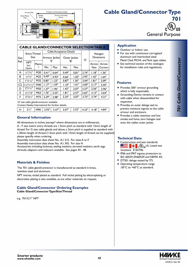
All dimensions in inches (except* where dimensions are in millimetres).A - F size metric entry threads are 1.5mm pitch as standard with 15mm length of thread. For G size cable glands and above, a 2mm pitch is supplied as standard with a 20mm length of thread (1.5mm pitch with 15mm length of thread can be supplied) please specifiy when ordering. Assembly instruction data sheet No. A.I. 315. For sizes A to F.Assembly instruction data sheet No. A.I. 342. For size H. Accessories including locknuts, sealing washers, serrated washers, earth tags, shrouds, adaptors and reducers available. See pages 44 - 48.
Outdoor or Indoor use. For use with continuous corrugated aluminum and interlocked steel Metal Clad, MCHL and Teck type cables. See technical section of the catalogue for installation rules and regulations.
Provides 360° armour grounding which is fully inspectable. Grounding Device remains in contact with cable when disassembled for inspection. Provides an outer deluge seal to prevent moisture ingress to the cable armour and enclosure. Provides a cable retention and low smoke and fume, zero halogen seal onto the cables outer jacket.
Cable Gland/Connector Ordering ExamplesCable Gland/Connector Type/Size/Thread
e.g. 701/C/1" NPT
IP66 and IP67 ingress protection to IEC 60529, EN60529 and NEMA 4X. DTS01 deluge tested by ITS. Operating temperature range -50°C to +60°C as standard.
Construction and test standards UL Listed wet
locations. E165706.
InternationalSmarter productswww.ehawke.com
CABLE GLAND/CONNECTOR SELECTION TABLE
SizeRef.
ABCC2DE
F
M20M25M32M40M50M63M75
Entry ThreadSize
Metric*
Cable Acceptance Details
Min. Max.
'G'AcrossFlats
AcrossCorners
HexagonDimensions
Min. Max.
Armour Jacket'E'
Outer Jacket'B'
½"/¾"
¾"/1"1"/1¼"
1¼"/1½"
NPTStd./
Option
2"/1½"
2½"/2"3"/2½"
701
Cab
le G
land
/Con
nect
or
General Purpose
701 Cable Gland/Connector Type
Technical Data
General Information
Features
Application
Materials & Finishes
HWK21 Feb '04
0.49"
0.66"0.87"1.10"1.42"1.81"2.24"
0.81"1.02"1.30"1.61"
2.07"2.57"3.07"
2.74"2.95"3.04"3.09"3.37"3.65"3.73"
0.41"0.49"0.85"1.17"1.37"1.76"2.29"
0.64"0.93"1.23"1.59"
1.96"2.55"
2.98"
1.18"1.42"1.81"2.17"2.56"3.15"3.74"
1.36"1.64"2.09"2.50"2.96"3.64"4.31"
3½" 3.47"2.93" 3.07" 3.52" 4.18"4.33" 4.84"H M90
'H' size cable gland/connector available. Contact Hawke International for further details.
Entr
y Thr
ead
'G' Approx (Compressed Length)
Ø 'B
'
DelugeBoot
Armour GroundingDevice
Ø 'E
'
Nickel Plated Hub
Armour Stop
The 701 cable gland/connector is manufactured as standard in brass, stainless steel and aluminum.
42
electroless plating is also available, as are other materials on request.NPT entries, nickel plated as standard. Full nickel plating by electroplating or

InternationalHWK21 Feb '04
43Smarter productswww.ehawke.com
Acc
esso
ries
Accessories
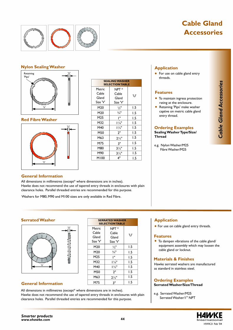
All dimensions in millimetres (except* where dimensions are in inches).Hawke does not recommend the use of tapered entry threads in enclosures with plainclearance holes. Parallel threaded entries are recommended for this purpose.
For use on cable gland entry threads.
To maintain ingress protection rating at the enclosure. Retaining 'Pips' make washer captive on metric cable gland entry thread. Ordering ExamplesSealing Washer Type/Size/Thread
e.g. Nylon Washer/M25 Fibre Washer/M25
For use on cable gland entry threads.
To dampen vibrations of the cable gland/ equipment assembly which may loosen the cable gland or locknut.
Hawke serrated washers are manufactured as standard in stainless steel.
Ordering ExamplesSerrated Washer/Size/Thread
e.g. Serrated Washer/M25 Serrated Washer/1" NPT
All dimensions in millimetres (except* where dimensions are in inches).Hawke does not recommend the use of tapered entry threads in enclosures with plainclearance holes. Parallel threaded entries are recommended for this purpose.
International44Smarter productswww.ehawke.com
SEALING WASHER SELECTION TABLE
MetricCableGlandSize 'V'
M20M20
M25M32M40M50M63
M75
'U'
M80M90M100
1.5
1.51.51.51.51.51.5
1.51.51.51.5
NPT *Cable GlandSize 'V'
¾"
2"
2½"
3"
1"1¼"1½"
½"
3½"3½"4"
SERRATED WASHER SELECTION TABLE
MetricCableGlandSize 'V'
M20M20
M25M32M40M50M63
M75
'U'
1.5
1.51.51.51.51.51.5
1.5
NPT * Cable GlandSize 'V'
¾"
2"
2½"
3"
1"1¼"1½"
½"
Cab
le G
land
Acc
esso
ries
Accessories Cable Gland
General Information
General Information
Red Fibre Washer
Nylon Sealing Washer Application
Features
Serrated Washer Application
Features
Materials & Finishes
HWK21 Feb '04
'V'
Retaining'Pips'
'V'
'U'
'U'
Washers for M80, M90 and M100 sizes are only available in Red Fibre.
'V'
'U'
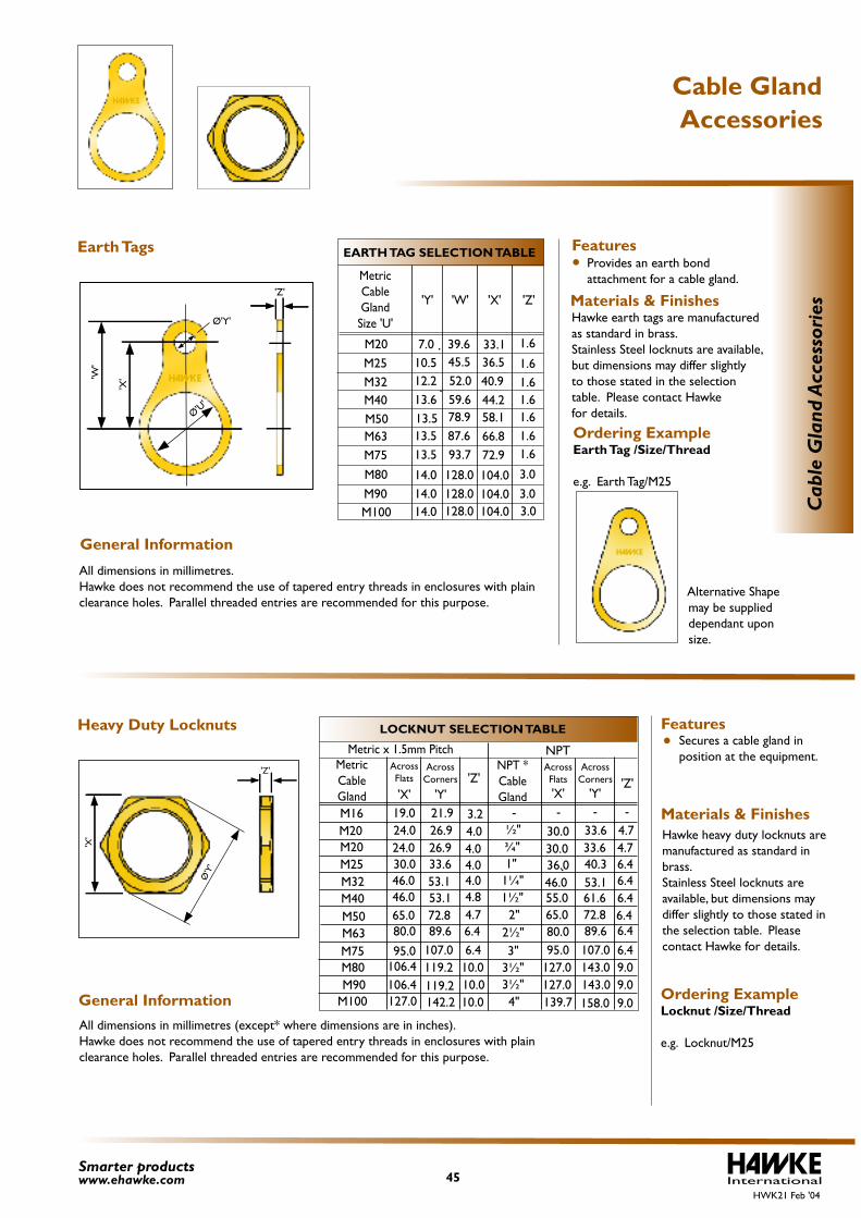
Ordering ExampleEarth Tag /Size/Thread
e.g. Earth Tag/M25
Hawke earth tags are manufactured as standard in brass.Stainless Steel locknuts are available,but dimensions may differ slightlyto those stated in the selectiontable. Please contact Hawke for details.
Provides an earth bond attachment for a cable gland.
Alternative Shape may be supplied dependant upon size.
Secures a cable gland in position at the equipment.
Ordering ExampleLocknut /Size/Thread e.g. Locknut/M25
Hawke heavy duty locknuts are manufactured as standard in brass.Stainless Steel locknuts are available, but dimensions may differ slightly to those stated in the selection table. Please contact Hawke for details.
International45Smarter productswww.ehawke.com
EARTH TAG SELECTION TABLE
MetricCableGlandSize 'U'
M20M25M32M40M50M63M75
'Z'
M80M90M100
'Y' 'W' 'X'
1.67.010.512.213.613.513.513.5
14.014.014.0
39.645.552.059.678.987.693.7
128.0128.0128.0
1.61.61.61.61.61.6
3.03.03.0
33.136.540.944.258.166.872.9
104.0104.0104.0
LOCKNUT SELECTION TABLE
MetricCableGland
NPT *CableGland
Metric x 1.5mm Pitch
'X' 'Y''Z'
'Y''Z'
AcrossFlats
'X'
AcrossFlats
NPTAcross
CornersAcross
Corners
30.036.046.055.065.080.095.0
127.0
139.7127.0
¾"
2"2½"3"
1"1¼"1½"
M20M20M16
M25M32M40M50M63M75M80M90
M100
24.030.046.046.065.080.0
95.0106.4
127.0
33.640.353.161.672.889.6107.0143.0
158.0
4.76.46.46.46.46.46.49.0
9.0
4.04.04.04.84.76.46.4
10.0
10.0
26.930.0½"24.0 33.6 4.74.026.9
19.0 3.221.9
33.653.153.172.889.6
107.0119.2
142.2
3½"106.4 143.0 9.010.0119.2 3½"
4"
- - --C
able
Gla
nd A
cces
sori
es
Accessories Cable Gland
General Information
General Information
Materials & Finishes
Features
Features
Materials & Finishes
Heavy Duty Locknuts
HWK21 Feb '04
Earth Tags
'W'
'X'
'Z'
'Z'
Ø'Y'
Ø'U'
'X'
Ø'Y
'
All dimensions in millimetres (except* where dimensions are in inches).Hawke does not recommend the use of tapered entry threads in enclosures with plainclearance holes. Parallel threaded entries are recommended for this purpose.
All dimensions in millimetres. Hawke does not recommend the use of tapered entry threads in enclosures with plainclearance holes. Parallel threaded entries are recommended for this purpose.
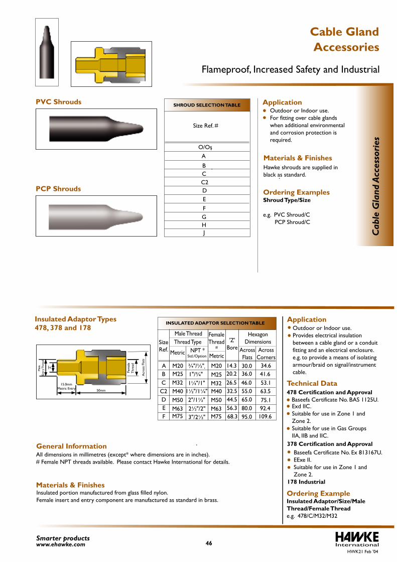
All dimensions in millimetres (except* where dimensions are in inches).# Female NPT threads available. Please contact Hawke International for details.
Outdoor or Indoor use. For fitting over cable glands when additional environmental and corrosion protection is required.
Hawke shrouds are supplied in black as standard.
Ordering ExamplesShroud Type/Size
e.g. PVC Shroud/C PCP Shroud/C
Outdoor or Indoor use. Provides electrical insulation between a cable gland or a conduit fitting and an electrical enclosure. e.g. to provide a means of isolating armour/braid on signal/instrument cable.
478 Certification and Approval Baseefa Certificate No. BAS 1125U. Exd IIC. Suitable for use in Zone 1 and Zone 2. Suitable for use in Gas Groups IIA, IIB and IIC.
Baseefa Certificate No. Ex 813167U. EExe II. Suitable for use in Zone 1 and Zone 2.178 Industrial Insulated portion manufactured from glass filled nylon.
Female insert and entry component are manufactured as standard in brass. Ordering ExampleInsulated Adaptor/Size/Male Thread/Female Threade.g. 478/C/M32/M32
Std./Option
International46Smarter productswww.ehawke.com
SHROUD SELECTION TABLE
Size Ref. #
O/OsA
BC
DE
F
C2
GHJ
INSULATED ADAPTOR SELECTION TABLE
Male Thread FemaleThreadThread TypeSize
Ref. NPT *
¾"/½"
2"/1½"2½"/2"3"/2½"
1"/¾"1¼"/1"
1½"/1¼"
ABCC2DEF
M20M25M32M40M50M63M75
M20M25M32M40M50M63M75
'Z'Bore
14.320.226.532.544.556.368.3
AcrossFlats
AcrossCorners
HexagonDimensions
30.036.046.055.065.080.095.0
34.641.653.163.575.192.4109.6
Cab
le G
land
Acc
esso
ries
Metric Metric#
Accessories Cable Gland
Flameproof, Increased Safety and Industrial
General Information
PVC Shrouds
PCP Shrouds
Application
Materials & Finishes
Insulated Adaptor Types478, 378 and 178
Application
Technical Data
378 Certification and Approval
Materials & Finishes
HWK21 Feb '04
'Z'
Acr
oss
Flat
s
Fe
mal
e
Thr
ead
M
ale
Entr
y Thr
ead
50mm
15.0mmMetric Entry
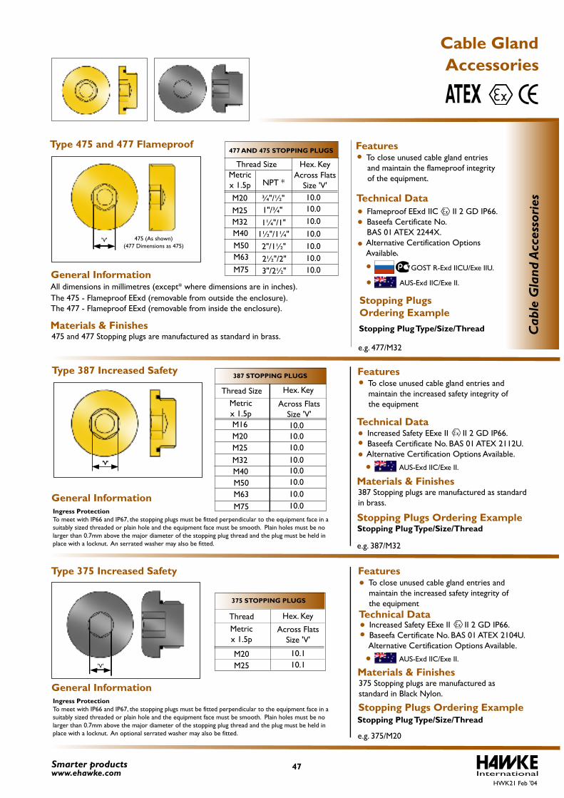
All dimensions in millimetres (except* where dimensions are in inches).
Flameproof EExd IIC II 2 GD IP66.Baseefa Certificate No. BAS 01 ATEX 2244X. Alternative Certification Options Available.
To close unused cable gland entries and maintain the flameproof integrity of the equipment.
GOST R-Exd IICU/Exe IIU.
475 and 477 Stopping plugs are manufactured as standard in brass.
Type 475 and 477 Flameproof
e.g. 477/M32
The 475 - Flameproof EExd (removable from outside the enclosure). The 477 - Flameproof EExd (removable from inside the enclosure).
Stopping Plug Type/Size/Thread
Hex. Key
To close unused cable gland entries andmaintain the increased safety integrity ofthe equipment
Ingress ProtectionTo meet with IP66 and IP67, the stopping plugs must be fitted perpendicular to the equipment face in a suitably sized threaded or plain hole and the equipment face must be smooth. Plain holes must be no larger than 0.7mm above the major diameter of the stopping plug thread and the plug must be held in place with a locknut. An serrated washer may also be fitted.
Ingress ProtectionTo meet with IP66 and IP67, the stopping plugs must be fitted perpendicular to the equipment face in a suitably sized threaded or plain hole and the equipment face must be smooth. Plain holes must be no larger than 0.7mm above the major diameter of the stopping plug thread and the plug must be held in place with a locknut. An optional serrated washer may also be fitted.
387 Stopping plugs are manufactured as standard in brass.
Increased Safety EExe II II 2 GD IP66.Baseefa Certificate No. BAS 01 ATEX 2112U. Alternative Certification Options Available.
e.g. 387/M32
Materials & Finishes
Stopping Plug Type/Size/Thread
To close unused cable gland entries andmaintain the increased safety integrity ofthe equipment
Increased Safety EExe II II 2 GD IP66.Baseefa Certificate No. BAS 01 ATEX 2104U. Alternative Certification Options Available.
Stopping Plug Type/Size/Thread
375 Stopping plugs are manufactured as standard in Black Nylon.
International47Smarter products
www.ehawke.com
¾"/½"
2"/1½"2½"/2"3"/2½"
1"/¾"1¼"/1"
1½"/1¼"
NPT *
M20M25M32M40M50M63M75
Metricx 1.5p
10.010.010.010.010.010.010.0
Thread SizeAcross Flats
Size 'V'
477 AND 475 STOPPING PLUGS
387 STOPPING PLUGS
375 STOPPING PLUGS
M20 10.110.1M25
Thread Hex. KeyMetricx 1.5p
Across FlatsSize 'V'
Cab
le G
land
Acc
esso
ries
M20 10.0M16 10.0
10.0
10.010.0
10.0
10.010.0
M25M32M40M50M63M75
Thread Size Hex. Key
Metricx 1.5p
Across FlatsSize 'V'
e.g. 375/M20
Accessories Cable Gland
ATEX
General Information
General Information
General Information
Technical Data
Features
Materials & Finishes
Stopping PlugsOrdering Example
Type 387 Increased Safety Features
Technical Data
Stopping Plugs Ordering Example
Type 375 Increased Safety
Technical Data
Features
Stopping Plugs Ordering Example
Materials & Finishes
HWK21 Feb '04
AUS-Exd IIC/Exe II.
AUS-Exd IIC/Exe II.
AUS-Exd IIC/Exe II.
'V' 475 (As shown)(477 Dimensions as 475)
'V''V'
'V'
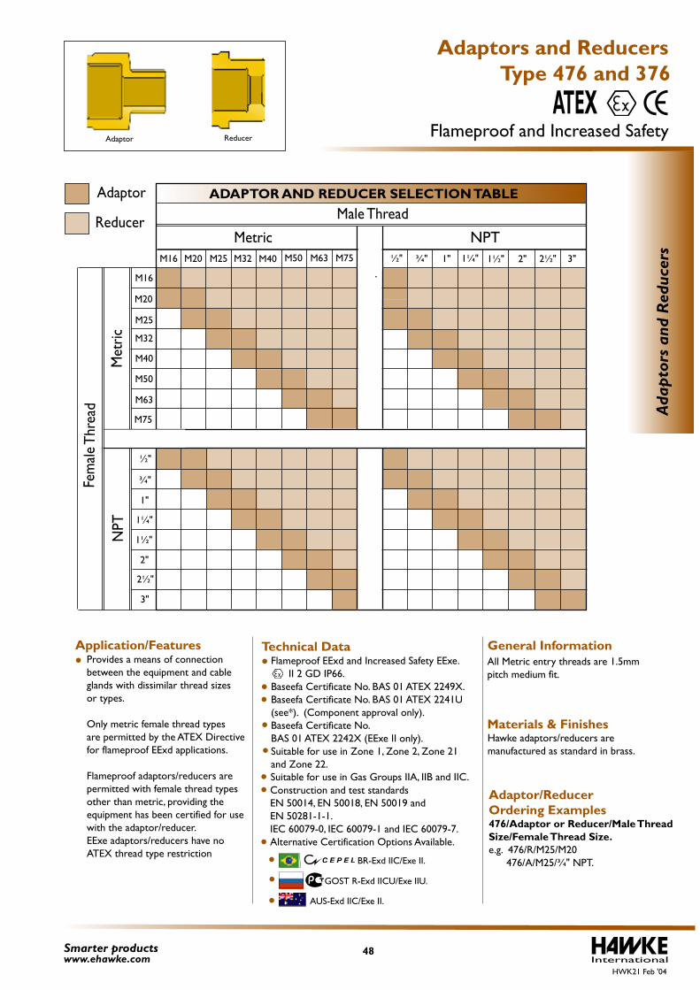
Materials & Finishes
Adaptor/Reducer Ordering Examples476/Adaptor or Reducer/Male Thread Size/Female Thread Size. e.g. 476/R/M25/M20 476/A/M25/¾" NPT.
Hawke adaptors/reducers are manufactured as standard in brass.
Construction and test standards EN 50014, EN 50018, EN 50019 and EN 50281-1-1. IEC 60079-0, IEC 60079-1 and IEC 60079-7.Alternative Certification Options Available.
Provides a means of connection between the equipment and cable glands with dissimilar thread sizes or types.
Only metric female thread typesare permitted by the ATEX Directive for flameproof EExd applications.
Flameproof adaptors/reducers are permitted with female thread types other than metric, providing the equipment has been certified for use with the adaptor/reducer.EExe adaptors/reducers have no ATEX thread type restriction
Adaptor
Reducer
All Metric entry threads are 1.5mm pitch medium fit.
GOST R-Exd IICU/Exe IIU.
BR-Exd IIC/Exe II.
Flameproof EExd and Increased Safety EExe. II 2 GD IP66. Baseefa Certificate No. BAS 01 ATEX 2249X. Baseefa Certificate No. BAS 01 ATEX 2241U (see*). (Component approval only). Baseefa Certificate No. BAS 01 ATEX 2242X (EExe II only). Suitable for use in Zone 1, Zone 2, Zone 21 and Zone 22.
Suitable for use in Gas Groups IIA, IIB and IIC.
International48Smarter products
www.ehawke.com
Ada
ptor
s an
d R
educ
ers
ADAPTOR AND REDUCER SELECTION TABLE
Metric NPTM16 M20 M25 M32
M16
M20
M25
M32
M40
M50
M63
M75
M50 M63 M75M40 ½" 1" 1¼" 2" 2½" 3"
Male Thread
1½"¾"
½"
1"
1¼"
2"
2½"
3"
1½"
¾"Fem
ale T
hrea
d
Met
ricN
PT
Type 476 and 376
Adaptors and Reducers
Flameproof and Increased SafetyATEX
General InformationTechnical DataApplication/Features
HWK21 Feb '04
AUS-Exd IIC/Exe II.
Adaptor Reducer
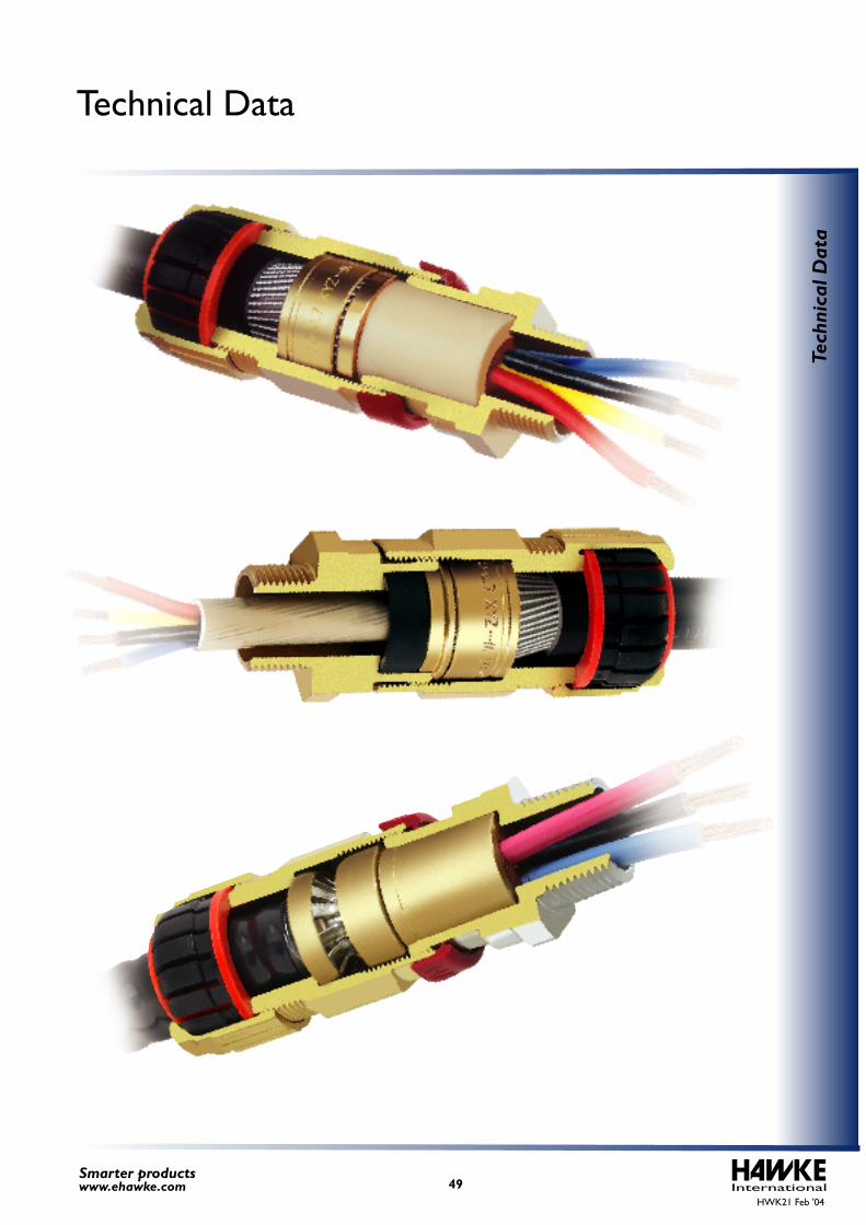
InternationalHWK21 Feb '04
49Smarter productswww.ehawke.com
Tech
nica
l Dat
a
Technical Data
The intent of this section of the catalogue is to identify important features that may be useful in the selection and installation of explosion protected electrical equipment.
Of flammable substances in the form of gases, vapours, mists, dusts or fibres
In which, after ignition has occurred, combustion spreads to the entire unburned mixtureUnder atmospheric conditionsWith air
An explosive atmosphere is defined as a mixture: -
There are numerous different regulations, codes, guidelines and standards for the design, installation and maintenance of electrical and non-electrical systems for use in potentially explosive atmospheres. The type of operational facility, geographic location, operator practice, local and national legislation, authority having jurisdiction etc. will determine many of the design and installation rules permitted. A fixed or floating petroleum facility located offshore, for example, would not be designed or classified in the same manner as an onshore petrochemical facility.
The purpose of area classification is to provide a basis for the correct selection, installation and location of electrical and non-electrical equipment in those areas. Areas must be classified depending on the properties of the flammable vapours, liquids, gases, mists, combustible dusts or fibres that may be present and the likelihood that a flammable or combustible concentration or quantity is present.
The aim of area classification is to avoid ignition of flammable releases that may occur in the operation of facilities. The intent is to reduce to an acceptable minimum level the probability of a flammable atmosphere and an ignition source occurring at the same time.
Area classification is the division of a facility into three-dimensional hazardous areas and non-hazardous areas and the sub-division of the hazardous area into 'Zones'.
Hazardous areas may be sub-divided into three Zones as follows: -
1.0 Potentially Explosive Atmospheres
2.0 Area Classification (Classification of Locations)
3.0 CENELEC and IEC3.1 Area Classification
HWK21 Feb '04International50
Smarter productswww.ehawke.com
Tech
nica
l Dat
a
Hawke Cable Glands and EnclosuresTechnical Data
Zone 0An area in which an explosive atmosphere is constantly present, or present for long periods.
An area in which an explosive atmosphere is likely to occur in normal operation.(Rough Guide: 10 hours or more / year but less than 1,000 hours / year)
An area in which an explosive atmosphere is not likely to occur in normal operation and if it occurs, it will exist only for a short time.(Rough Guide: Less than 10 hours / year)
Zone 1
Zone 2
Flammable gases and vapours
For further information on the classification of hazardous areas, see: -
Model Code of Safe Practice in the Petroleum Industry, Part 15: Area Classification Code for Petroleum Installations, IP 15
Classification of areas where dusts are, or may be, present
Electrical Apparatus for Explosive Gas Atmospheres, Classification
Electrical apparatus for use in the presence of combustible dustPart 3: Classification of areas where combustible dusts are, or may be, present
Electrical Apparatus for Explosive Gas Atmospheres, Classification of Hazardous Areas
Classification of the hazardous area
Where applicable, the gas, vapour or dust classification in relation to the group or sub-group of the electrical apparatus
External influences and ambient temperature
Temperature class or ignition temperature of the gas, liquid, vapours, mist, dust or fibre
A Classification Society may also enforce requirements for the design and installation of facilities. These requirements, which are in addition to statutory requirements, may influence the design and installation of the electrical systems. Classification Societies include ABS, DNV and Lloyds Register.
There are numerous regulation codes, guidelines and standards for the design, selection and installation of electrical installation in potentially explosive atmospheres. These requirements are in addition to the requirements for installations in non-hazardous areas.
There are several types of protection, i.e. construction techniques, available for electrical apparatus in hazardous areas. The type of protection permitted will depend upon the applicable installation codes and rules to be adopted.
The selection of electrical apparatus should be in accordance with the following: -
3.2 Classification Society
3.3 Design and Installation of Electrical Systems for Hazardous (Classified) Areas
IEC 60079-10 ---
---
---
---
---
IEC 61241-3(Proposed Changeto IEC 61241-10)
IEC 60079-10
PR EN 50281-3
Institute of Petroleum
HWK21 Feb '04International51
Smarter productswww.ehawke.com
Tech
nica
l Dat
a
Zone 20An area in which combustible dust, as a cloud, is present continuously or frequently, during normal operation, in sufficient quantity to be capable of producing an explosive concentration of combustible dust in a mixture with air
An area, in which combustible dust, as a cloud, is occasionally present during normal operation, in a sufficient quantity to be capable of producing an explosive concentration of combustible dust in a mixture with air.
An area, in which combustible dust, as a cloud, may occur infrequently and persist for only a short period, or in which accumulations of layers of combustible dust may give rise to an explosive concentration of combustible dust in mixture with air.
Zone 21
Zone 22
Combustible Dusts
Hawke Cable Glands and EnclosuresTechnical Data
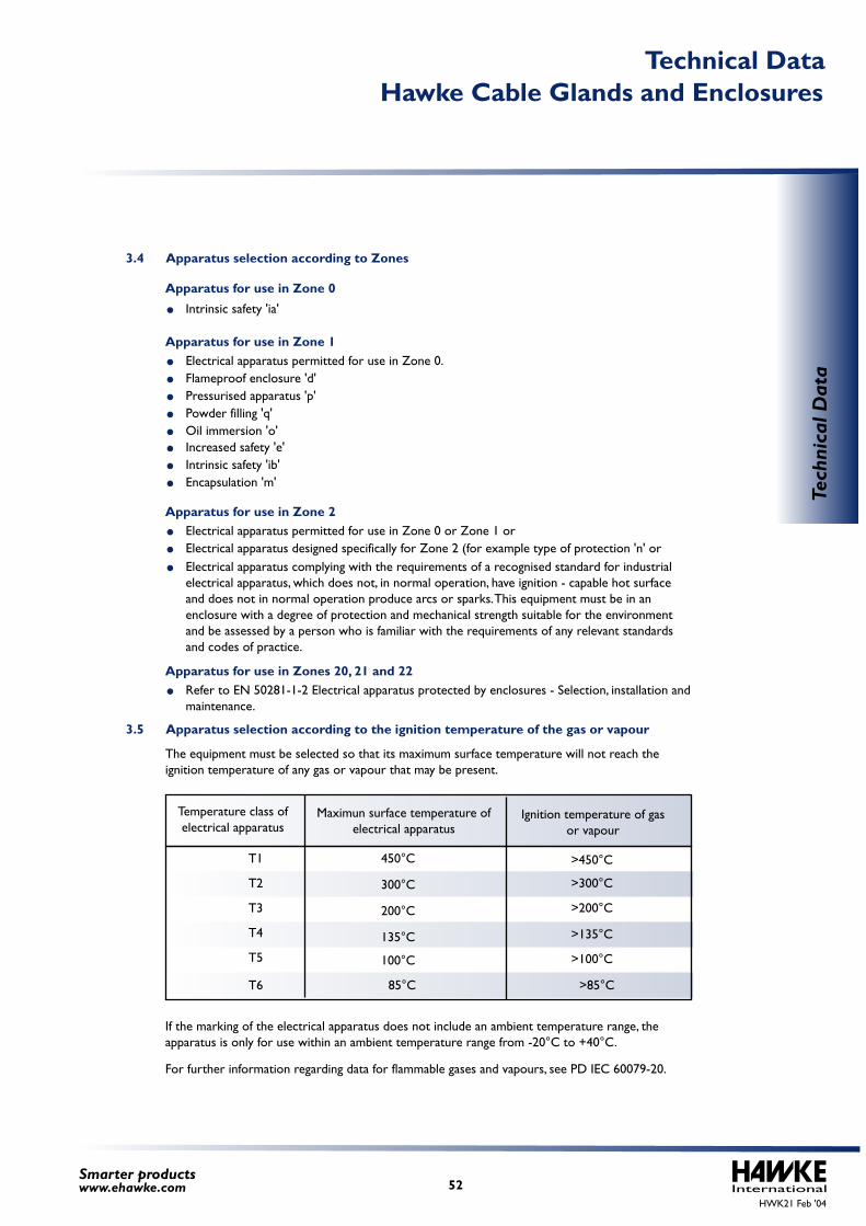
T1
T2
T3
T4
T5
T6
450°C
300°C
200°C
135°C
100°C
85°C
>450°C
>300°C
>200°C
>135°C
>100°C
>85°C
Temperature class of electrical apparatus
Ignition temperature of gas or vapour
Maximun surface temperature of electrical apparatus
3.4 Apparatus selection according to Zones
3.5 Apparatus selection according to the ignition temperature of the gas or vapour
Apparatus for use in Zone 0
Apparatus for use in Zone 1
Intrinsic safety 'ia'
Electrical apparatus permitted for use in Zone 0.
Apparatus for use in Zone 2Electrical apparatus permitted for use in Zone 0 or Zone 1 or
Apparatus for use in Zones 20, 21 and 22Refer to EN 50281-1-2 Electrical apparatus protected by enclosures - Selection, installation and maintenance.
The equipment must be selected so that its maximum surface temperature will not reach the ignition temperature of any gas or vapour that may be present.
If the marking of the electrical apparatus does not include an ambient temperature range, the apparatus is only for use within an ambient temperature range from -20°C to +40°C.
For further information regarding data for flammable gases and vapours, see PD IEC 60079-20.
Electrical apparatus designed specifically for Zone 2 (for example type of protection 'n' orElectrical apparatus complying with the requirements of a recognised standard for industrial electrical apparatus, which does not, in normal operation, have ignition - capable hot surface and does not in normal operation produce arcs or sparks. This equipment must be in an enclosure with a degree of protection and mechanical strength suitable for the environment and be assessed by a person who is familiar with the requirements of any relevant standards and codes of practice.
Flameproof enclosure 'd'Pressurised apparatus 'p'Powder filling 'q'Oil immersion 'o'Increased safety 'e'Intrinsic safety 'ib'Encapsulation 'm'
HWK21 Feb '04International52
Smarter productswww.ehawke.com
Tech
nica
l Dat
a
Hawke Cable Glands and EnclosuresTechnical Data
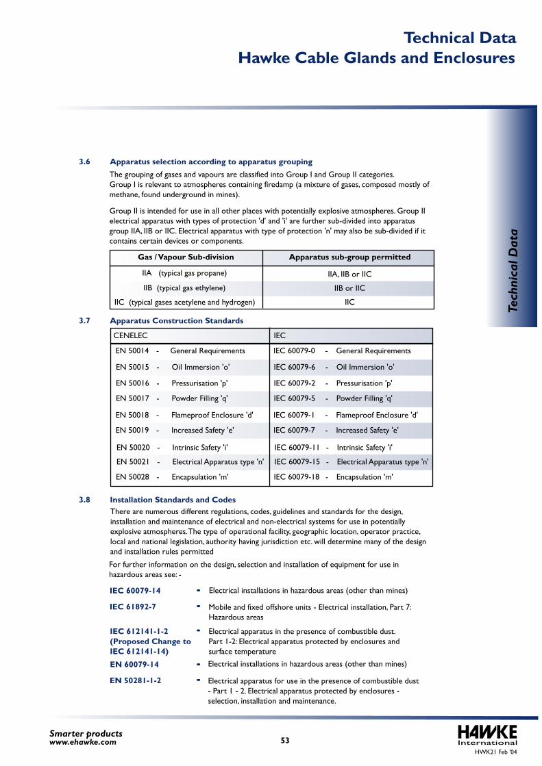
IIA, IIB or IIC
IIB or IIC
IIC
IIB (typical gas ethylene)
IIA (typical gas propane)
IIC (typical gases acetylene and hydrogen)
Gas / Vapour Sub-division Apparatus sub-group permitted
The grouping of gases and vapours are classified into Group I and Group II categories.Group I is relevant to atmospheres containing firedamp (a mixture of gases, composed mostly of methane, found underground in mines).
Group II is intended for use in all other places with potentially explosive atmospheres. Group II electrical apparatus with types of protection 'd' and 'i' are further sub-divided into apparatus group IIA, IIB or IIC. Electrical apparatus with type of protection 'n' may also be sub-divided if it contains certain devices or components.
There are numerous different regulations, codes, guidelines and standards for the design, installation and maintenance of electrical and non-electrical systems for use in potentially explosive atmospheres. The type of operational facility, geographic location, operator practice, local and national legislation, authority having jurisdiction etc. will determine many of the design and installation rules permitted
Electrical apparatus for use in the presence of combustible dust - Part 1 - 2. Electrical apparatus protected by enclosures - selection, installation and maintenance.
Electrical installations in hazardous areas (other than mines)
Mobile and fixed offshore units - Electrical installation, Part 7: Hazardous areas
Electrical apparatus in the presence of combustible dust.Part 1-2: Electrical apparatus protected by enclosures and surface temperature
Electrical installations in hazardous areas (other than mines)
For further information on the design, selection and installation of equipment for use in hazardous areas see: -
---
---
---
---
---
IEC 61892-7
IEC 60079-14
EN 60079-14
IEC 612141-1-2(Proposed Change toIEC 612141-14)
EN 50281-1-2
3.6 Apparatus selection according to apparatus grouping
3.7 Apparatus Construction Standards
3.8 Installation Standards and Codes
HWK21 Feb '04International53
Smarter productswww.ehawke.com
Tech
nica
l Dat
a
Hawke Cable Glands and EnclosuresTechnical Data
EN 50014- General Requirements
EN 50015- Oil Immersion 'o'
EN 50028- Encapsulation 'm'
EN 50021- Electrical Apparatus type 'n'
EN 50020- Intrinsic Safety 'i'
EN 50019- Increased Safety 'e'
EN 50018- Flameproof Enclosure 'd'
EN 50017- Powder Filling 'q'
EN 50016- Pressurisation 'p'
IEC 60079-0 -General Requirements
IEC 60079-6 -Oil Immersion 'o'
IEC 60079-18-Encapsulation 'm'
IEC 60079-15-Electrical Apparatus type 'n'
IEC 60079-11-Intrinsic Safety 'i'
IEC 60079-7 -Increased Safety 'e'
IEC 60079-1 -Flameproof Enclosure 'd'
IEC 60079-5 -Powder Filling 'q'
IEC 60079-2 -Pressurisation 'p'
CENELEC IEC
HWK21 Feb '04International54
Smarter productswww.ehawke.com
Tech
nica
l Dat
a
Hawke Cable Glands and EnclosuresTechnical Data
Electrical apparatus for use in the presence of combustible dust atmosphere - Part 17: Inspection and maintenance
Inspection and maintenance of electrical installations in hazardous areas (other than mines)
For information regarding the installation and maintenance of equipment for use in hazardous see: -
ATEX is the term used when referring to the European Unions (EU) Directive 94/9/EC
The Directive covers: -
The ATEX Directive main objectives are to guarantee the free circulation of goods within the European Union by aligning the technical and legal requirements of the Member States.
The Directive covers electrical and non-electrical equipment and protective systems intended for use in potentially explosive atmospheres in mining and surface industries.
To ensure compliance with the Directive, equipment must meet with the essential requirements specified in the Directive and be marked with the CE marking.
The process of ensuring that equipment complies with the Directive, conformity assessment procedure(s) must be complied with. These procedures may involve a Notified Body. A Notified body is a body that is independent of the product manufacturer and assesses conformity of the products and the manufacturer with the Directive. The Notified Body has to be approved and appointed by its government.
The Directive is named: - "Approximation of the laws of the Member States concerning equipment and protective systems intended for use in potentially explosive atmospheres".
"ATEX" is derived from the French "Atmosphères Explosibles".
equipment and products that have potential ignition sourcesprotective systems - products that control the effects of incipient explosions
safety devices - products that may be outside a potentially explosive atmosphere but that have an explosion safety function.components - products that are intended to form parts of equipment or protective systems
Conformity assessment procedures include, but are not limited by: -
The ATEX Directive came into force on a voluntary basis on 1st March 1996 and will become mandatory from the 1st July 2003 and all products within its scope will have to comply before being placed on the market or put into service.
EC Type examination - including testing and inspection of a product design, where appropriate
Production Quality Assurance - including the assessment, periodic auditing, testing and inspection of production samples, where appropriate, and of the manufacturers quality system.
Product Verification - the inspection and/or testing of each production item for conformity with the type that was subjected to EC Type Examination
Internal Control of Production - the verification by the manufacturer that the product design and each production item conform to either harmonised European Standards or the essential requirements or a combination of the two
4.0 ATEX 94/9/EC Directive
3.9 Inspection Standards and Codes
---
---
IEC 60079-17
IEC 61241-17
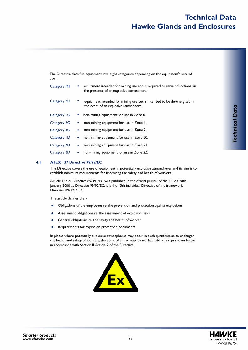
HWK21 Feb '04International55
Smarter productswww.ehawke.com
Tech
nica
l Dat
a
Hawke Glands and EnclosuresTechnical Data
The Directive classifies equipment into eight categories depending on the equipment's area of use: -
The Directive covers the use of equipment in potentially explosive atmospheres and its aim is to establish minimum requirements for improving the safety and health of workers.
Article 137 of Directive 89/391/EC was published in the official journal of the EC on 28th January 2000 as Directive 99/92/EC, it is the 15th individual Directive of the framework Directive 89/391/EEC.
The article defines the: -
equipment intended for mining use and is required to remain functional in the presence of an explosive atmosphere.
equipment intended for mining use but is intended to be de-energised in the event of an explosive atmosphere.
non-mining equipment for use in Zone 0.
non-mining equipment for use in Zone 1.
non-mining equipment for use in Zone 2.
non-mining equipment for use in Zone 20.
non-mining equipment for use in Zone 21.
non-mining equipment for use in Zone 22.
Obligations of the employees re. the prevention and protection against explosions
Assessment obligations re. the assessment of explosion risks.
General obligations re. the safety and health of worker
Requirements for explosion protection documents
In places where potentially explosive atmospheres may occur in such quantities as to endanger the health and safety of workers, the point of entry must be marked with the sign shown below in accordance with Section II, Article 7 of the Directive.
4.1 ATEX 137 Directive 99/92/EC
---Category M1
---Category M2
---
---
---
Category 1G
Category 2G
Category 3G
---Category 1D
---Category 2D
---Category 2D
Ex
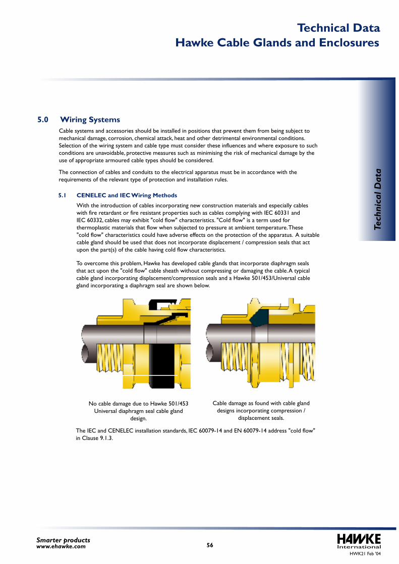
5.1 CENELEC and IEC Wiring Methods
Cable systems and accessories should be installed in positions that prevent them from being subject to mechanical damage, corrosion, chemical attack, heat and other detrimental environmental conditions. Selection of the wiring system and cable type must consider these influences and where exposure to such conditions are unavoidable, protective measures such as minimising the risk of mechanical damage by the use of appropriate armoured cable types should be considered.
The connection of cables and conduits to the electrical apparatus must be in accordance with the requirements of the relevant type of protection and installation rules.
With the introduction of cables incorporating new construction materials and especially cables with fire retardant or fire resistant properties such as cables complying with IEC 60331 and IEC 60332, cables may exhibit "cold flow" characteristics. "Cold flow" is a term used for thermoplastic materials that flow when subjected to pressure at ambient temperature. These "cold flow" characteristics could have adverse effects on the protection of the apparatus. A suitable cable gland should be used that does not incorporate displacement / compression seals that act upon the part(s) of the cable having cold flow characteristics.
To overcome this problem, Hawke has developed cable glands that incorporate diaphragm seals that act upon the "cold flow" cable sheath without compressing or damaging the cable. A typical cable gland incorporating displacement/compression seals and a Hawke 501/453/Universal cable gland incorporating a diaphragm seal are shown below.
The IEC and CENELEC installation standards, IEC 60079-14 and EN 60079-14 address "cold flow" in Clause 9.1.3.
Cable damage as found with cable gland designs incorporating compression /
displacement seals.
No cable damage due to Hawke 501/453 Universal diaphragm seal cable gland
design.
5.0 Wiring Systems
HWK21 Feb '04International56
Smarter productswww.ehawke.com
Tech
nica
l Dat
a
Hawke Cable Glands and EnclosuresTechnical Data
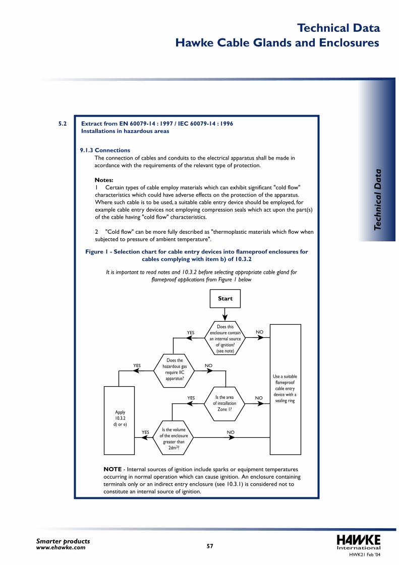
NOTE - Internal sources of ignition include sparks or equipment temperatures occurring in normal operation which can cause ignition. An enclosure containing terminals only or an indirect entry enclosure (see 10.3.1) is considered not to constitute an internal source of ignition.
Figure 1 - Selection chart for cable entry devices into flameproof enclosures for cables complying with item b) of 10.3.2
It is important to read notes and 10.3.2 before selecting appropriate cable gland for flameproof applications from Figure 1 below
The connection of cables and conduits to the electrical apparatus shall be made in acordance with the requirements of the relevant type of protection.
Notes:1 Certain types of cable employ materials which can exhibit significant "cold flow" characteristics which could have adverse effects on the protection of the apparatus. Where such cable is to be used, a suitable cable entry device should be employed, for example cable entry devices not employing compression seals which act upon the part(s) of the cable having "cold flow" characteristics.
2 "Cold flow" can be more fully described as "thermoplastic materials which flow when subjected to pressure of ambient temperature".
9.1.3Connections
5.2 Extract from EN 60079-14 : 1997 / IEC 60079-14 : 1996 Installations in hazardous areas
Start
YES
YES
YES
YES NO
NO
NO
NODoes this
enclosure containan internal source
of ignition?(see note)
Does thehazardous gas
require IICapparatus?
Is the areaof installation
Zone 1?
Use a suitableflameproofcable entry
device with asealing ring
Is the volumeof the enclosure
greater than2dm3?
Apply10.3.2
d) or e)
HWK21 Feb '04International57
Smarter productswww.ehawke.com
Tech
nica
l Dat
a
Hawke Cable Glands and EnclosuresTechnical Data
It is essential that cable entry systems comply with all the requirements referred to in the appropriate apparatus standard, that the cable entry device is appropriate to the type of cable employed, maintains the respective method of protection and is in accordance with clause 9.
Where cables enter into flameproof apparatus via flameproof bushings through the wall of the enclosure which are part of the apparatus (indirect entry), the parts of the bushings outside the flameproof enclosure will be protected in accordance with one of the types of protection listed in IEC 79-0. Normally the exposed part of the bushings will be within a terminal compartment which will either be another flameproof enclosure or will be protected by protection type 'e'. Where the terminal compartment is Ex'd', then the cable system shall comply with 10.3.2. Where the terminal compartment is Ex'e', then the cable system shall comply with 11.3.
Where cables enter into flameproof apparatus directly, the cable system shall comply with 10.3.2.
10.3 Cable Entry Systems
10.3.1General
The cable entry system shall comply with one of the following:
a)cable entry device in compliance with IEC 79-1 and the particular type of cable intended for use with that device;
b)thermoplastic, thermosetting or elastomeric cable which is substantially compact and circular, has extruded bedding and the fillers, if any, are non-hygroscopic, may utilize flameproof cable entry devices, incorporating a sealing ring selected in accordance with figure1;
c)mineral insulated cable with or without plastic outer covering with appropriate flameproof cable entry device;
d)flameproof sealing device (for example a stopper box or sealing chamber) specified in the apparatus documentation or having component approval and employing cable entry devices appropriate to the cables used. The sealing devices such as stopper boxes or sealing chambers shall incorporate compound or other appropriate seals which permit stopping around indivudual cores. Sealing devices shall be fitted at the point of entry of cables to the apparatus;
e)flameproof cable entry devices incorporating compound filled seals around the individual cores or other equivalent sealing arrangements;
f)other means which maintain the integrity of the flameproof enclosure.
NOTE - Where a factory-made termination of the encapsulated type is used, no attempt should be made to interfere with the connection to the apparatus or to replace the cable.
10.3.2Selection
Hazardous Area Information
HWK21 Feb '04International58
Smarter productswww.ehawke.com
Tech
nica
l Dat
a
Hawke Cable Glands and EnclosuresTechnical Data
Cables and conduits shall be installed in accordance with clause 9 and the following additional requirements concerning cable entries and conductor terminations.
11.3 Wiring Systems
11.3.1General
The connection of cables to increased safety apparatus shall be effected by means of cable entry devices appropriate to the type of cable used. They shall maintain protection type 'e' and shall incorporate a suitable sealing component to achieve IP54 degree of protection of the terminal enclosure.
NOTES
1 To meet IP 54 it may be necessary to seal between the cable and the enclosure (for example by means of a sealing washer or thread sealant.
2 Threaded cable entry devices into threaded cable entry plates or enclosures of 6mm or greater thickness need no additional sealing between the cable entry device and the entry plate or enclosure providing the axis of the cable entry device is perpendicular to the external surface of the cable entry plate or enclosure.
11.3.2Cable Entry Devices
Hazardous Area Information
ACKNOWLEDGEMENTExtracts from BS EN 60079-14 : 1997 reproduced with the permission of BSI under licence no. PD/1998 1818 and 1920. Complete editions of the standards can be obtained by post from BSI Customer Services, 389 Cjhiswick high Road, London. W4 4AL
A minimum ingress protection rating of IP54 is required for increased safety equipment. To meet with this requirement it may be necessary to provide a seal between the cable gland and the equipment, for example, by the use of a sealing washer or thread sealant. Where cable glands are fitted into non-metallic enclosures, metallic enclosures with a painted type finish or enclosures with non-threaded clearance holes, additional ingress and earthing / bonding considerations may be necessary. Please refer to the sealing washer, earthtag, serrated washer and locknut accessories shown in the catalogue.
The cable entry device, e.g. cable gland, must comply with all the requirements referred to in the appropriate Standard, be appropriate to the cable type. and maintain the type 'e' integrity of the equipment.
5.3Wiring Methods for Type of Protection 'e' - Increased Safety:
HWK21 Feb '04International59
Smarter productswww.ehawke.com
Tech
nica
l Dat
a
Hawke Cable Glands and EnclosuresTechnical Data
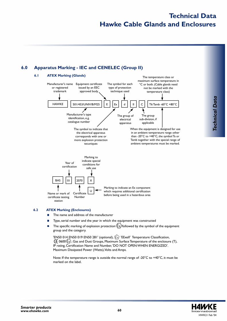
The name and address of the manufacturer
Manufacturer's name or registered trademark
HAWKE 501/453/UNIV/B/M25
Equipment certificate issued by an EEC approved body
The symbol to indicate that the electrical apparatus
corresponds with one or more explosion protection
tecuniques
The group sub-division, if
applicable
The group of electrical apparatus
Year of certification
Marking to indicate special conditions for
safe use
Marking to indicate an Ex component which requires additional certification before being used in a hazardous areaCertificate
NumberName or mark of certificate testing
station
When the equipment is designed for use in an ambient temperature range other than -20°C to +40°C, the symbol Ta or Tamb together with the special range of ambient temperatures must be marked.
Manufacturer's type identification, e.g. catalogue number
The symbol for each type of protection
technique used
The temperature class or maximum surface temperature in °C or both. (Cable glands need
not be marked with the temperature class)
Type, serial number and the year in which the equipment was constructed
The specific marking of explosion protection followed by the symbol of the equipment group and the category.
6.0 Apparatus Marking - IEC and CENELEC (Group II)
6.2 ATEX Marking (Enclosures)
6.1 ATEX Marking (Glands)
'EN50 014 EN50 019 EN50 281' (optional), 'EExeII' Temperature Classification, 0600 , Gas and Dust Groups, Maximum Surface Temperature of the enclosure (T),IP rating, Certification Name and Number, 'DO NOT OPEN WHEN ENERGIZED'. Maximum Dissipated Power (Watts), Volts and Amps.
Note: If the temperature range is outside the normal range of -20°C to +40°C, it must be marked on the label.
E Ex
01 X
U
2070BAS
d II C T6 Tamb -60°C +80°C
HWK21 Feb '04International60
Smarter productswww.ehawke.com
Tech
nica
l Dat
a
Hawke Cable Glands and EnclosuresTechnical Data
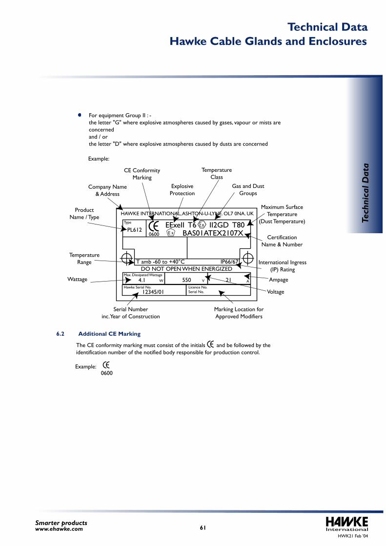
Example:
CE ConformityMarking
ExplosiveProtection
Gas and DustGroups
Maximum Surface Temperature
(Dust Temperature)
CertificationName & Number
Company Name& Address
ProductName / Type
TemperatureRange International Ingress
(IP) Rating
Ampage
Voltage
0600Example:
Wattage
Serial Numberinc. Year of Construction
Marking Location forApproved Modifiers
TemperatureClass
For equipment Group II : -the letter "G" where explosive atmospheres caused by gases, vapour or mists are concernedand / orthe letter "D" where explosive atmospheres caused by dusts are concerned
6.2 Additional CE Marking
The CE conformity marking must consist of the initials and be followed by the identification number of the notified body responsible for production control.
DO NOT OPEN WHEN ENERGIZED
HAWKE INTERNATIONAL, ASHTON-U-LYNE. OL7 0NA. UK
T amb -60 to +40°C IP66/67
Max. Dissipated Wattage
Hawke Serial No.
0600
Licence No.Serial No.
VW4.1
12345/01
PL612
550 21 A
Type EExeII T6 II2GD T80BAS01ATEX2107X
HWK21 Feb '04International61
Smarter productswww.ehawke.com
Tech
nica
l Dat
a
Hawke Cable Glands and EnclosuresTechnical Data
Only electrical equipment that does not jeopardise the safety of people, domestic animals and property, is permitted on the market.
Only electrical equipment, that satisfies the CE marking requirements of the LVD, is in compliance.
Electrical equipment is not required to be tested or marked for approval by an independent third party
Be constructed so they do not cause excessive electromagnetic interference and are not unduly affected by electromagnetic interference;
In the case of certain radio-transmitting equipment, be subject to EC type examination by a notified body; and
Carry CE marking
Electrical equipment for use in potentially explosive atmospheres is usually certified, listed or approved by a recognised Certification Body or Test House. In Europe, there are numerous Certification Bodies such as BASEEFA 2001 Limited and SIRA in the UK. In North America, there are many recognised Certification Bodies and testing laboratories such as UL, FM and the CSA. The definition of "Approved" by the NEC is "Acceptable to the authority having jurisdiction". The definition "Listed" by the NEC is "Equipment, materials or services included in a list published by an organisation that is acceptable to the authority having jurisdiction". Further information is given in the NEC.
Enforcement is the responsibility of each member state within its national jurisdiction.
The regulations apply to all electrical equipment, except where extensions apply, that is designed for use between 50 and 1000 volts ac or 75 and 1500 volts dc.
Only components, which are in themselves "electrical equipment", need satisfy the Low Voltage Directive.
Cable glands are not in themselves "electrical equipment" and therefore do not fall within the scope of the LVD.
Cable glands are not considered to come within the scope of the Directive, however we have carried out independent third-party testing on the EMC shielding effectiveness of our armoured type cable glands fitted onto single wire armoured and braided-type cables. The electromagnetic ingress between the cable sample (perfect connection) and that of the cable sample fitted with the cable gland was of such a small magnitude that it could be regarded as within acceptable uncertainty of measurement. As such, it can be concluded that the shielding effectiveness of single wire armoured or braided cable is maintained when fitted with an appropriate Hawke armoured type cable gland.
The Low voltage Directive 73/23/EEC embodies a number of principles: -
The CE Marking is intended to facilitate the free movement of products within the European Union. By affixing CE marking to products, the manufacturer is making a legal declaration that the product meets with the appropriate requirements of all relevant European Directives. CE marking only applies to products within the scope of the Directives. It should not be applied to products if they are outside the
Most electrical and electronic products made or sold in the EU must: -
7.0 CE Marking
8.0 Certification / Listing / Approvals
7.2 Low Voltage Directive
7.1 EMC, Electromagnetic Compatibility Directive
HWK21 Feb '04International62
Smarter productswww.ehawke.com
Tech
nica
l Dat
a
Hawke Cable Glands and EnclosuresTechnical Data
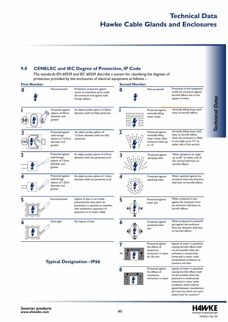
The standards EN 60529 and IEC 60529 describe a system for classifying the degrees of protection provided by the enclosures of electrial equipment as follows :-
9.0 CENELEC and IEC Degree of Protection, IP Code
Typical Designation : IP66
First Number Second Number
50
12.5
15cm min.
1M
0 Non-protected Protection of persons against access to hazardous parts inside the enclosure and against solid foreign objects
1 Protected againstobjects of 50mmdiameter andgreater
An object probe, sphere of 50mm diameter, shall not fully penetrate
Protected againstsolid foreign objects of 12.5mmdiameter andgreater
An object probe, sphere of 12.5mm diameter, shall not fully penetrate
Protected againstsolid foreign objects of 2.5mmdiameter andgreater
An object probe, sphere of 2.5mm diameter, shall not penetrate at all
2
3
Protected againstsolid foreign objects of 1.0mmdiameter andgreater
An object probe, sphere of 1.0mm diameter, shall not penetrate at all
4
Dust-protected Ingress of dust is not totallyprevented, but dust shall not penetrate in a quantity to interfere with satisfactory operation of apparatus or to impair safety
5
Dust-tight No ingress of dust6
0 Non-protected Protection of the equipmentinside the enclosure againstharmful effects due to theingress of water
1 Protected againstvertically fallingwater drops
Vertically falling drops shallhave no harmful effects
Protected againstvertically fallingwater drops whenenclosure tilted up to 15°
Vertically falling drops shallhave no harmful effectswhen the enclosure is tiltedat any angle up to 15° oneither side of the vertical
2
Protected against splashing water
4
3 Protected againstspraying water
Water sprayed at an angleup to 60° on either side ofthe vertical shall have noharmful effects
Water splashed against theenclosure from any directionshall have no harmful effects
Protected againstwater jets
Water projected in jetsagainst the enclosure fromany direction shall have noharmful effects
5
Protected againstpowered water jets
Water projected in powerfuljets against the enclosurefrom any direction shall haveno harmful effects
6
Protected againstthe effects oftemporary immersion in waterfor 30 mins
Ingress of water in quantitiescausing harmful effects shallnot be possible when theenclosure is temporarilyimmersed in water understandardised conditions ofpressure and time
7
Protected againstthe effects ofcontinuous immersion in water
Ingress of water in quantities causing harmful effects shallnot be possible when theenclosure is continuouslyimmersed in water underconditions which shall beagreed between manufacturerand user but which are moresevere than for numeral 7
8
HWK21 Feb '04International63
Smarter productswww.ehawke.com
Tech
nica
l Dat
a
Hawke Cable Glands and EnclosuresTechnical Data
HWK21 Feb '04International64
Smarter productswww.ehawke.com
Tech
nica
l Dat
a
Hawke Cable Glands and EnclosuresTechnical Data
Energising the equipment (where appropriate) for 60 minutes prior to the deluge test, then interrupting the electrical power at the start of the deluge test and resuming after 60 minutes until the completion of the deluge test.
Carrying out insulation resistance testing before and after pre-conditioning and after the deluge test, where applicable.
Carrying out pre-conditioning by exposure to vibration and thermal ageing at 90% relative humidity and at a temperature 20k above the equipments maximum service temperature and/or at least 80°C of any appropriate seals.
Carrying out deluge test using a deluge chamber fitted with deluge nozzles that apply a salt water solution deluge pressure within the range of 3.5 bar to 4.5 bar at a water temperature in the range of 5°C to 10°C for 3-hours.
The objective of the IECEx Scheme is to facilitate international trade in electrical equipment intended for use in potentially explosive atmospheres by eliminating the need for multiple national certification. The IECEx Scheme provides a means for manufacturers to obtain Certificates of Conformity that will be accepted at national level in all participating countries. A Certificate of Conformity may be obtained from any certification body accepted into the scheme. The objective of the IECEx Scheme is world-wide acceptance of one standard, one certificate, and one mark.
For the IEC scheme to achieve its objective, every applicable national standard will need to be identical to the corresponding IEC standard. A transition period will be necessary to allow time for participating IECEx Scheme countries to align their national standards with the IEC standards and work towards national acceptance of IECEx Certificates of Conformity and the IECEx mark.
Testing includes: -
The protection of the enclosure and the equipment inside against external influences or conditions, such as: mechanical impacts, corrosion, corrosive solvents, solar radiation, icing moisture (e.g. produced by condensation), and explosive atmospheres, are matters that should be dealt with by the relevant product Standard.
There are additional and supplementary optional letters to the above coding; these designators are A, B, C & D and H, M, S & W, and further information can be found in the relevant Standard(s).
On offshore facilities, equipment may be located in areas subject to emergency deluge systems. Equipment that has been evaluated as certified for use in hazardous areas may not be suitable for use in these locations. A testing method for electrical equipment to be installed in areas subject to deluge systems, DTS01, has been prepared by the Explosion and Fire Hazards Group of ERA Technology (now known as ITS) in collaboration with Shell UK Exploration and Production Ltd.
Area classification is the division of a facility into a two or three-dimensional hazardous location, a non-hazardous location and the sub-division of the hazardous location into 'Divisions' or 'Zones'.
Hazardous (classified) locations may be sub-divided as follows: -
10.0IECEx Scheme
11.0North American Hazardous (Classified) Locations
9.1 Deluge Ingress Protection
11.1 Area Classification
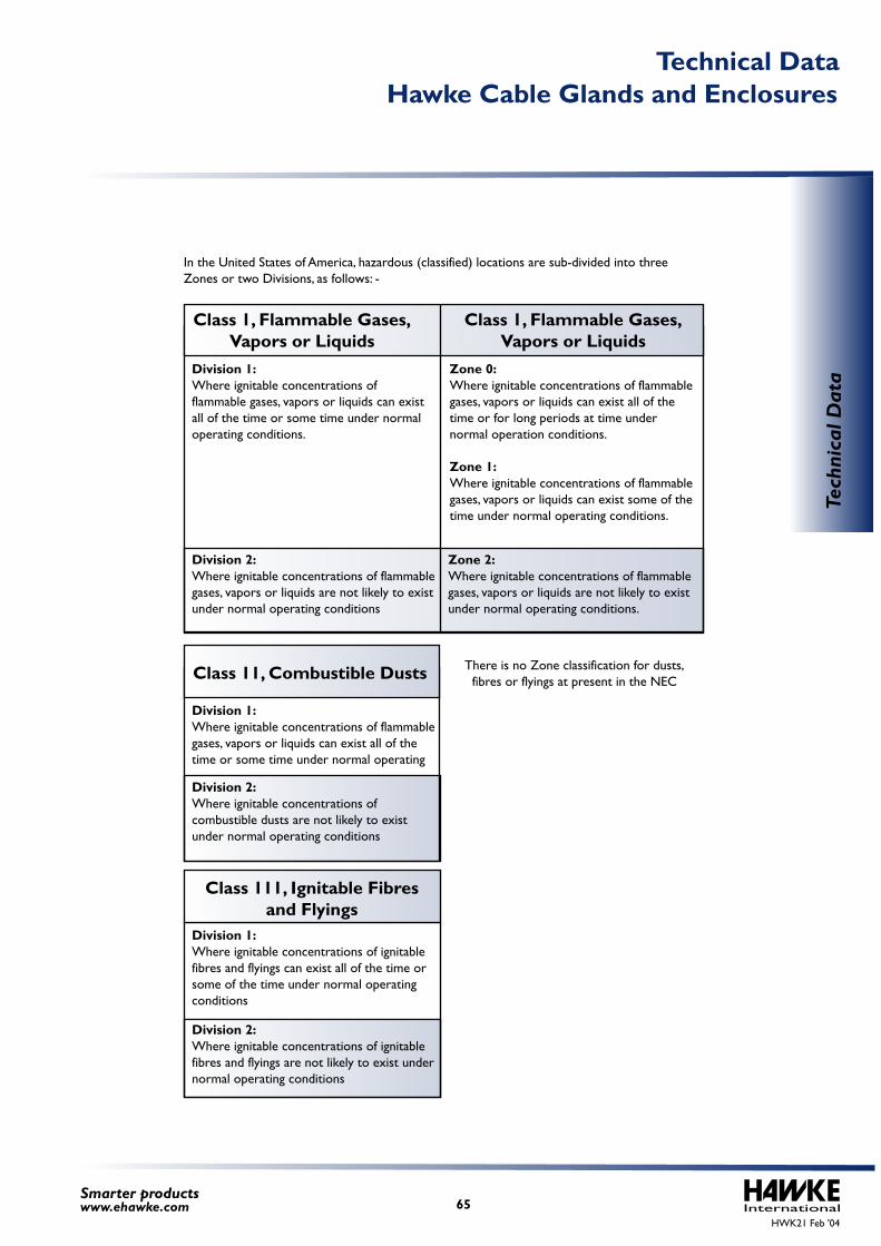
HWK21 Feb '04International65
Smarter productswww.ehawke.com
In the United States of America, hazardous (classified) locations are sub-divided into three Zones or two Divisions, as follows: -
Division 1:Where ignitable concentrations of flammable gases, vapors or liquids can exist all of the time or some time under normal operating conditions.
Zone 0:Where ignitable concentrations of flammable gases, vapors or liquids can exist all of the time or for long periods at time under normal operation conditions.
Zone 1:Where ignitable concentrations of flammable gases, vapors or liquids can exist some of the time under normal operating conditions.
Division 2:Where ignitable concentrations of flammable gases, vapors or liquids are not likely to exist under normal operating conditions
Zone 2:Where ignitable concentrations of flammable gases, vapors or liquids are not likely to exist under normal operating conditions.
Class 1, Flammable Gases, Vapors or Liquids
Class 1, Flammable Gases, Vapors or Liquids
Division 1:Where ignitable concentrations of flammable gases, vapors or liquids can exist all of the time or some time under normal operating
There is no Zone classification for dusts, fibres or flyings at present in the NEC
Division 2:Where ignitable concentrations of combustible dusts are not likely to exist under normal operating conditions
Class 11, Combustible Dusts
Division 1:Where ignitable concentrations of ignitable fibres and flyings can exist all of the time or some of the time under normal operating conditions
Division 2:Where ignitable concentrations of ignitable fibres and flyings are not likely to exist under normal operating conditions
Class 111, Ignitable Fibres and Flyings
Tech
nica
l Dat
a
Hawke Cable Glands and EnclosuresTechnical Data
Explosion-proof
For further information on the classification of hazardous (classified) locations see: -
Intrinsically safePurged / pressurised (type X or Y)
Apparatus for use in Class 1, Division 1Intrinsic safety AEx ia
Class I, Division 1 intrinsically safe
Apparatus for use in Class 1, Zone 0
Any Class I, Zone 0 or 1 method
Any Class I, Division 1 or 2 method
Type of protection AEx n
Apparatus for use in Class 1, Zone 2
Any Class 1, Division 1 method
Non-incendiveNon-sparking device
Purged / pressurised (type Z)Hermetically sealed
Oil immersion
Apparatus for use in Class 1, Division 2Any Class I, Zone 0 methodAny Class I, Division 1 methodFlameproof, AEx dIncreased safety, AEx eIntrinsic safety, AEx ibPurged pressurised, AEx pPowder filling, AEx qOil immersion, AEx o Encapsulation, AEx m
Apparatus for use in Class 1, Zone 1
Intrinsically safe equipment listed for use in Class I, Division 1, locations for the same gas or a permitted by Section 505-7(d) of the NEC, and with suitable temperature rating is permitted in Class I, Zone 0 locations.
Equipment approved for use in Class I, Division 1 or listed for use in Class I, Zone 0 locations for the same gas, or as permitted by Section 505-7(d) of the NEC, and with a suitable temperature rating is permitted in Class I, Zone 1 locations.
Equipment approved for use in Class I, Division 1 or Division 2 locations for the same gas, or as permitted by Section 505-7(d) of the NEC, and with a suitable temperature rating is permitted in Class I, Zone 2 locations.
Equipment listed as classified for use in Class I locations is not necessarily acceptable for Class II locations as it may not be dust-tight or operate at a safe temperature with a dust covering.
NEC, NFPA 70 - National Electric Code, NFPA 70NFPA 30 - Flammable and Combustible Liquids CodeNFPA 497 - Recommended Practice for the Classification of Flammable Liquids, Gases or Vapours and of Hazardous (Classified) Locations for Electrical Installations in Chemical Process AreasNFPA 499 - Recommended Practice for the Classification of Combustible Dusts and of Hazardous (Classified) Locations for Electrical Installations in Chemical Process AreasANSI/API RP500 - Recommended Practice for Classification of Locations for Electrical Installations at Petroleum Facilities Classified as Class I, Division 1 and Division 2ANSI/API RP 505 - Classification of Locations for Electrical Installations at Petroleum Facilities Classified as Class I, Zone 0, Zone 1 or Zone 2
11.2 Apparatus selection according to Class 1
HWK21 Feb '04International66
Smarter productswww.ehawke.com
Tech
nica
l Dat
a
Hawke Cable Glands and EnclosuresTechnical Data
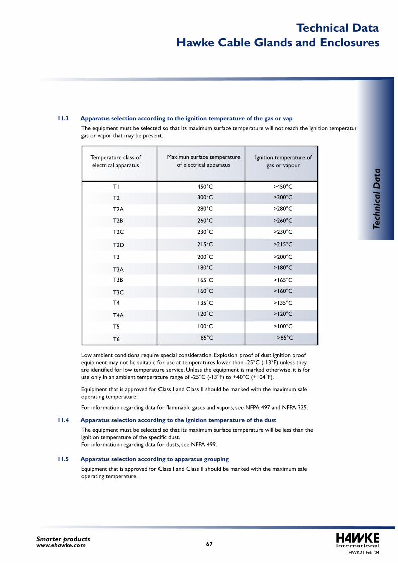
The equipment must be selected so that its maximum surface temperature will not reach the ignition temperature of any gas or vapor that may be present.
The equipment must be selected so that its maximum surface temperature will be less than the ignition temperature of the specific dust.For information regarding data for dusts, see NFPA 499.
Equipment that is approved for Class I and Class II should be marked with the maximum safe operating temperature.
Low ambient conditions require special consideration. Explosion proof of dust ignition proof equipment may not be suitable for use at temperatures lower than -25°C (-13°F) unless they are identified for low temperature service. Unless the equipment is marked otherwise, it is for use only in an ambient temperature range of -25°C (-13°F) to +40°C (+104°F).
Equipment that is approved for Class I and Class II should be marked with the maximum safe operating temperature.
For information regarding data for flammable gases and vapors, see NFPA 497 and NFPA 325.
T1
T2
T2A
T2B
T2C
T2D
450°C
300°C
280°C
260°C
230°C
215°C
T3
T3A
200°C
165°CT3B
T3C 160°C
135°CT4
T4A 120°C
100°CT5
T6 85°C
180°C
>450°C
>300°C
>280°C
>260°C
>230°C
>215°C
>200°C
>165°C
>160°C
>135°C
>120°C
>100°C
>85°C
>180°C
Temperature class of electrical apparatus
Ignition temperature of gas or vapour
Maximun surface temperature of electrical apparatus
11.3 Apparatus selection according to the ignition temperature of the gas or vap
11.4 Apparatus selection according to the ignition temperature of the dust
11.5 Apparatus selection according to apparatus grouping
HWK21 Feb '04International67
Smarter productswww.ehawke.com
Tech
nica
l Dat
a
Hawke Cable Glands and EnclosuresTechnical Data
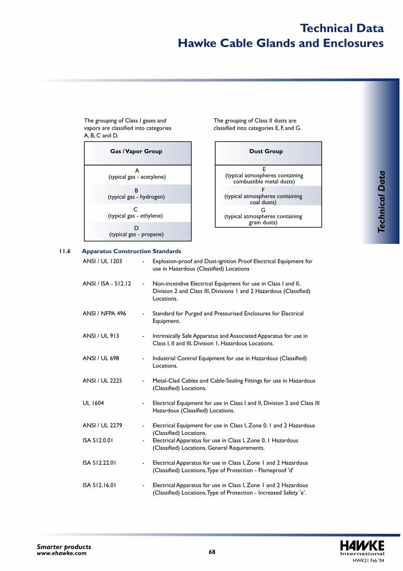
The grouping of Class I gases and vapors are classified into categories A, B, C and D.
The grouping of Class II dusts are classified into categories E, F, and G.
ANSI / UL 1203 - Explosion-proof and Dust-ignition Proof Electrical Equipment for use in Hazardous (Classified) Locations
ANSI / ISA - S12.12 - Non-incendive Electrical Equipment for use in Class I and II, Division 2 and Class III, Divisions 1 and 2 Hazardous (Classified) Locations.
ANSI / NFPA 496 - Standard for Purged and Pressurised Enclosures for Electrical Equipment.
ANSI / UL 913 - Intrinsically Safe Apparatus and Associated Apparatus for use in Class I, II and III, Division 1, Hazardous Locations.
ANSI / UL 698 - Industrial Control Equipment for use in Hazardous (Classified) Locations.
ANSI / UL 2225 - Metal-Clad Cables and Cable-Sealing Fittings for use in Hazardous (Classified) Locations.
UL 1604 - Electrical Equipment for use in Class I and II, Division 2 and Class III Hazardous (Classified) Locations.
ANSI / UL 2279 - Electrical Equipment for use in Class I, Zone 0, 1 and 2 Hazardous (Classified) Locations.ISA S12.0.01 - Electrical Apparatus for use in Class I, Zone 0, 1 Hazardous (Classified) Locations, General Requirements.
ISA S12.22.01 - Electrical Apparatus for use in Class I, Zone 1 and 2 Hazardous (Classified) Locations, Type of Protection - Flameproof 'd'
ISA S12.16.01 - Electrical Apparatus for use in Class I, Zone 1 and 2 Hazardous (Classified) Locations, Type of Protection - Increased Safety 'e'.
B(typical gas - hydrogen)
D(typical gas - propane)
A(typical gas - acetylene)
C(typical gas - ethylene)
Gas / Vapor Group
E(typical atmospheres containing
combustible metal dusts)F
(typical atmospheres containing coal dusts)
G(typical atmospheres containing
grain dusts)
Dust Group
11.6 Apparatus Construction Standards
HWK21 Feb '04International68
Smarter productswww.ehawke.com
Tech
nica
l Dat
a
Hawke Cable Glands and EnclosuresTechnical Data
NEC, NFPA 70 -National Electrical Code (NEC)
USCG 45 CFR Parts 110 - 113 -Shipping, Sub-Chapter J, Electrical Engineering
ANSI / API RP 14F -Recommended Practice for Design and Installatin of Electrical Systems for Fixed and Floating Offshore Petroleum Facilities for Unclassified and Class 1, Division 1 and Division 2 Locations.
API RP 14FZ -Rcommended Practice for Design and Installation of Electrical systems for fixed and floating offshore petroleum facilities for Unclassified and Class 1, Zone 0, Zone 1 and Zone 2 Locations.
Type MC cable, listed for use, with a gas / vapor tight continuous corrugated aluminum sheath, an overall jacket of suitable polymeric material, separate grounding conductors, in accordance with Sections 250-122 and 501-4 of the NEC, and provided with termination fittings listed for he application, e.g. Hawke type 711 cable gland/connector.
Type ITC cable, listed for use with a gas / vapor tight continuous aluminum sheath, an overall jacket of suitable polymeric material in accordance with Section 501-4 of the NEC and provided with termination fittings listed for the application, e.g. Hawke type 711 cable gland/connector.
Threaded rigid metal conduit, threaded steel intermediate metal conduit, or type MI cable with termination fittings approved for the location and in accordance with Section 501-4 of
Cable systems and accessories should be installed in positions that prevent them from being subject to mechanical damage, corrosion, chemical attack, heat and other detrimental environmental conditions. Selection of the wiring system and cable type must consider these influences and where exposure to such conditions are avoidable, protective measures such as minimising the risk of mechanical damage by the use of appropriate armoured cable types should be considered.
The connection of cables and conduits to the electrical apparatus must be in accordance with the requirements of the relevant type of protection and installation rules.
In Class I, Division 1 locations, the NEC permits the following wiring methods: -
All boxes, fittings and joints must be explosion-proof.
Hawke Type 711CableGland/Connector
12.1 National Electrical Code (NEC) Wiring Methods
12.0Wiring Systems
HWK21 Feb '04International69
Smarter productswww.ehawke.com
Tech
nica
l Dat
a
Hawke Cable Glands and EnclosuresTechnical Data
11.7 Installation Standards and Codes
Type MC, MV, ITC, PLTC, TC or MI cable with approved termination fittings in accordance with Section 501-4 of the NEC.
Threaded rigid metal conduit, threaded steel intermediate metal conduit.
Non-incendive field wiring using any of the methods suitable for wiring in ordinary locations in accordance with Section 501-4 of the NEC.
In Class I, Division 2 locations, the NEC permits the following wiring methods: -
Boxes, fittings and joints need not be explosion-proof except as required by the NEC code.
HWK21 Feb '04International70
Smarter productswww.ehawke.com
Tech
nica
l Dat
a
Hawke Cable Glands and EnclosuresTechnical Data
Cables must be sealed at the point of entrance into enclosures that require to be approved for Class I locations. A sealing fitting must comply with the above criteria given in "Cable Seals, Class I, Division 1".
Electrical installations in hazardous (classified) locations must comply with the general requirements of Section 43 of the IEEE standard 45 and either the NEC Articles 500 - 505 or IEC 60079 series publications.
A NRTL approved cable sealing fitting e.g. barrier type cable gland, must be fitted onto cables where they enter explosion-proof enclosures.
Cables must be sealed at the termination. The sealing fitting, e.g. a barrier type cable gland, must provide a seal against the passage of gas or vapours through the fitting. Type MC cables with multi-conductors, a gas / vapour tight continuous corrugated aluminum sheath and an overall jacket with a suitable polymeric material must be sealed with an appropriate fitting, e.g. Hawke type 711, after removing the cables jacket and all other coverings so that the sealing compound surrounds each individual insulated conductor. Cables with twisted pairs and shielded cables require the removal of the shielded material or separation of the twisted pairs unless the fitting, e.g. cable gland, is an approved means which minimises the entrance of gases or vapours and prevents propagation of flame into the cable core. If the fitting complies with this requirement, there will be information provided in the fittings installation instructions detailing the means to achieve the seal. Additional testing may be required on the fitting and the style and type of cable to show compliance with the sealing requirements.
A NRTL approved cable sealing fitting e.g. barrier type cable gland, must be fitted onto cables that enter explosion-proof enclosures.
Further guidance is given in Section 501-5(d) of the NEC.
Hawke Type 711Cable Gland/Connector
12.2 Cable Seals, Class 1, Division 1
12.3 Cable Seals, Class 1, Division 2
12.4 United State Coast Guard - Wiring Methods
Marine shipboard cables that are permitted for use, must meet all the requirements of either IEEE standard 45, IEC 60092-3 and the applicable flammability requirements. Cables constructed to IEC 60092-3 must meet with the flammability requirements of IEC 60332-3, Category A.
Metal-clad (type MC) cables that are permitted for use, must have a continuous corrugated gas tight, vapor-tight, and water-tight sheath of aluminum or other suitable metal that is close fitting around the conductors and with fillers. The MC cable must have an overall jacket of an impervious PVC or thermoset material and be certified or listed to UL 1569.
In hazardous (classified) locations, the USCG 46 CFR Sub-Chapter J, permits the following wiring methods: -
Hawke Type 753Cable Gland/Connector
HWK21 Feb '04International71
Smarter productswww.ehawke.com
Tech
nica
l Dat
a
Hawke Cable Glands and EnclosuresTechnical Data
For information on other wiring methods permitted and further information, refer to Subpart 111-60 of the USCG 46 CFR.
Each cable entry into explosion-protected equipment must be made with an appropriate fitting or cable gland that maintains the integrity of the equipment.
Cables with multi-conductors that enter explosion-proof enclosures, must be sealed with an appropriate fitting, e.g. barrier type cable gland, after removing the cables jacket and all other coverings so that the sealing compound surrounds each individual insulated conductor. Cables with twisted pairs and shielded cables require the removal of the shielded material or separation of the twisted pairs unless the fitting, e.g. barrier type cable gland, is an approved means which minimises the entrance of gases or vapours and prevents propagation of flame into the cable core. If the fitting complies with this requirement, there will be information provided in the fittings installation instructions detailing the means to achieve the seal. Additional testing may be required on the fitting, and the style and type of cable to show compliance with the sealing requirements.
12.4.1
Type MC-HL metal clad cables as defined in UL 2225.
Armored marine shipboard cable with an overall impervious sheath over the armor, constructed in accordance with UL 1309, and listed as "Shipboard Cable Marine" by a National Recognised Testing Laboratory (NRTL). This wiring method is a departure from the NEC.
Type ITC cable that is NRTL - listed for use in Class I, Division 1 locations with a gas / vapor tight continuous corrugated aluminum sheath and with an overall PVC or other suitable polymeric jacket.
Threaded rigid copper-free aluminum conduit.
Threaded rigid steel, hot dipped galvanized conduit, coated with PVC, or other suitable material, and with the interior protected by an additional means.
An NRTL approved cable sealing fitting, e.g. barrier type cable gland complying with UL 2225, must be fitted onto cables where they enter explosion-proof enclosures.
For fitting requirements of cables with multi-conductors, twisted pairs or shielded conductors into explosion proof equipment. See clause 12.4.1.
The equipment grounding path should be carefully considered when using Shipboard Cables or type TC cables, as these may not inherently provide a grounding means. The armor of Shipboard Cables should be grounded but can not be used as the grounding conductor. An appropriate sized grounding conductor should be included in each cable.
For further information and other wiring methods acceptable for Division 1, refer to Clause 6.4.2.2 of the API RP14F.
The API RP 14F Recommended Practice for the design and installation of electrical systems for fixed and floating offshore petroleum facilities recommends the following wiring methods for hazardous (classified) locations.
12.5 American Petroleum Institute - Wiring Methods
Class 1, Division 1
Type MC-HL metal clad cables as defined in UL 2225.
Armored marine shipboard cable with an overall impervious sheath over the armor, constructed in accordance with UL 1309, and listed as "Shipboard Cable Marine" by a National Recognised Testing Laboratory (NRTL). This wiring method is a departure from the NEC.
Type ITC cable that is NRTL - listed for use in Class 1, Division 1 locations with a gas / vapor tight continuous corrugated aluminum sheath and with an overall PVC or other suitable polymeric jacket.
Threaded rigid copper-free aluminum conduit.
Threaded rigid steel, hot dipped galvanized conduit, coated with PVC, or other suitable material, and with the interior protected by an additional means.
The API RP 14 FZ, Recommended Practice for the design and installation of electrical systems for fixed and floating offshore petroleum facilities for unclassified and Class I, Zone 0, Zone 1 and Zone 2 locations, recommends the following wiring methods for hazardous (classified) locations.
Non-armored marine shipboard cable, with an overall impervious jacket in accordance with UL 1309 and listed as "Shipboard Cable Marine" by a NRTL. This wiring method is a departure from the NEC.
For further information and other wiring methods acceptable for Zone 1, refer to Clause 6.4.2.2 of the API RP14FZ.
For fitting requirements of cables with multi-conductors, twisted pairs or shielded conductors into explosion proof equipment. See clause 12.4.1.
For fitting requirements of cables with multi-conductors, twisted pairs or shielded conductors into explosion proof equipment. See clause 12.4.1.
Class 1, Zone 1
Class 1, Zones 0, 1 and 2
Wiring methods as recommended for use in Division 1.
Type MC cable with a gas / vapour tight continuous corrugated aluminum sheath, an overall PVC or other suitable polymeric jacket, and grounding conductors in accordance with NEC 250-122.
Non-armored marine shipboard cable, with an overall impervious jacket in accordance with UL 1309 and listed as "Shipboard Cable Marine" by a NRTL. This wiring method is a departure from the NEC.
Additional wiring methods acceptable for Division 2 include type PLTC, ITC, TC and MV cables. It is recommended that an overall PVC or other suitable polymeric material jacket is included for these cable types.
For additional information, refer to Clause 6.4.2.3 of API RP14F.
HawkeType 710Cable Gland/Connector
In Division I locations, all electrical equipment (except intrinsically safe systems and equipment inside purged enclosures) should be explosion-proof.
In Division 2 locations, the equipment does not need to be explosion-proof, except where necessary to maintain the integrity of the installation.
Further information on the use of equipment is given in Clause 6.4.7 of API RP14F.
An NRTL approved cable sealing fitting, e.g. barrier type cable gland complying with UL 2225, must be fitted onto cables where they enter explosion-proof enclosures.
Class 1, Division 2
HWK21 Feb '04International72
Smarter productswww.ehawke.com
Tech
nica
l Dat
a
Hawke Cable Glands and EnclosuresTechnical Data
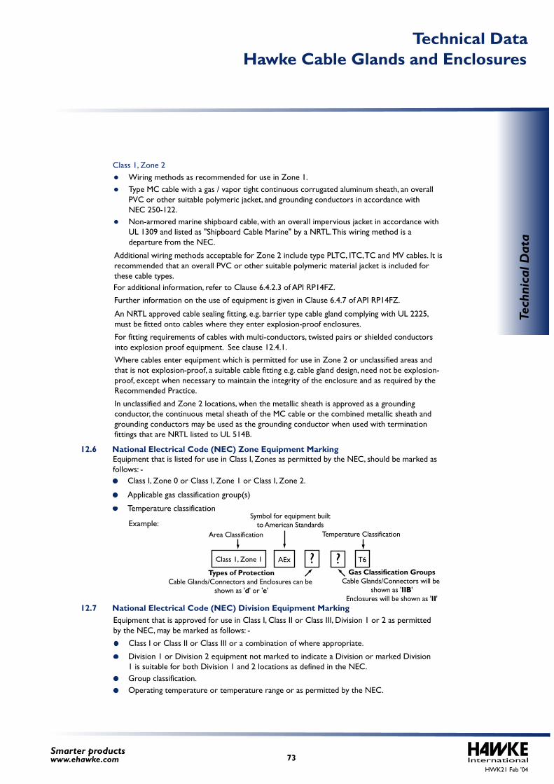
Wiring methods as recommended for use in Zone 1.Type MC cable with a gas / vapor tight continuous corrugated aluminum sheath, an overall PVC or other suitable polymeric jacket, and grounding conductors in accordance with NEC 250-122.Non-armored marine shipboard cable, with an overall impervious jacket in accordance with UL 1309 and listed as "Shipboard Cable Marine" by a NRTL. This wiring method is a departure from the NEC.
Additional wiring methods acceptable for Zone 2 include type PLTC, ITC, TC and MV cables. It is recommended that an overall PVC or other suitable polymeric material jacket is included for these cable types.
Further information on the use of equipment is given in Clause 6.4.7 of API RP14FZ.
An NRTL approved cable sealing fitting, e.g. barrier type cable gland complying with UL 2225, must be fitted onto cables where they enter explosion-proof enclosures.
For additional information, refer to Clause 6.4.2.3 of API RP14FZ.
For fitting requirements of cables with multi-conductors, twisted pairs or shielded conductors into explosion proof equipment. See clause 12.4.1.
Where cables enter equipment which is permitted for use in Zone 2 or unclassified areas and that is not explosion-proof, a suitable cable fitting e.g. cable gland design, need not be explosion-proof, except when necessary to maintain the integrity of the enclosure and as required by the Recommended Practice.
In unclassified and Zone 2 locations, when the metallic sheath is approved as a grounding conductor, the continuous metal sheath of the MC cable or the combined metallic sheath and grounding conductors may be used as the grounding conductor when used with termination fittings that are NRTL listed to UL 514B.
Class 1, Zone 2
HWK21 Feb '04International73
Smarter productswww.ehawke.com
Tech
nica
l Dat
aArea Classification Temperature Classification
Types of ProtectionCable Glands/Connectors and Enclosures can be
shown as 'd' or 'e'
Gas Classification GroupsCable Glands/Connectors will be
shown as 'IIB'Enclosures will be shown as 'II'
Symbol for equipment built to American Standards
Class 1, Zone 1 AEx T6? ?
Hawke Cable Glands and EnclosuresTechnical Data
Class I, Zone 0 or Class I, Zone 1 or Class I, Zone 2.
Applicable gas classification group(s)
Temperature classification
Class I or Class II or Class III or a combination of where appropriate.
Division 1 or Division 2 equipment not marked to indicate a Division or marked Division 1 is suitable for both Division 1 and 2 locations as defined in the NEC.Group classification.Operating temperature or temperature range or as permitted by the NEC.
Example:
Equipment that is approved for use in Class I, Class II or Class III, Division 1 or 2 as permitted by the NEC, may be marked as follows: -
Equipment that is listed for use in Class I, Zones as permitted by the NEC, should be marked as follows: -
12.6 National Electrical Code (NEC) Zone Equipment Marking
12.7 National Electrical Code (NEC) Division Equipment Marking
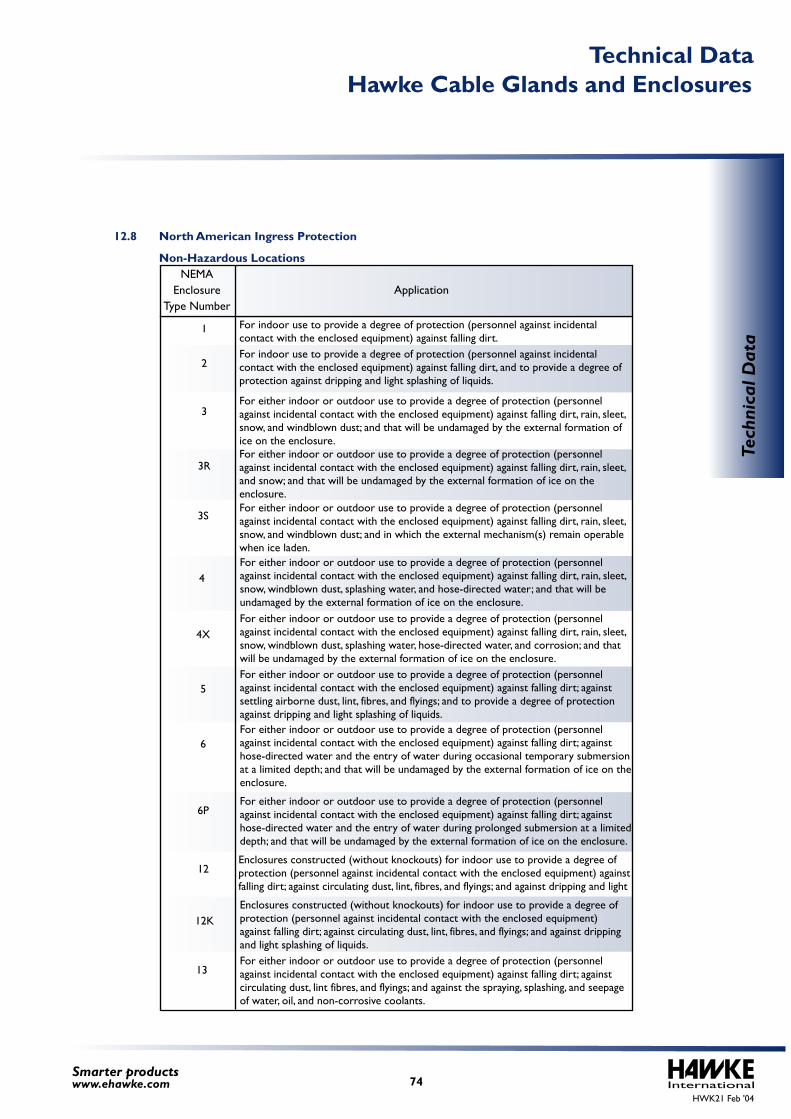
12.8 North American Ingress Protection
Non-Hazardous LocationsNEMA
EnclosureType Number
Application
For either indoor or outdoor use to provide a degree of protection (personnel against incidental contact with the enclosed equipment) against falling dirt, rain, sleet, snow, windblown dust, splashing water, and hose-directed water; and that will be undamaged by the external formation of ice on the enclosure.
4
For either indoor or outdoor use to provide a degree of protection (personnel against incidental contact with the enclosed equipment) against falling dirt, rain, sleet, snow, windblown dust, splashing water, hose-directed water, and corrosion; and that will be undamaged by the external formation of ice on the enclosure.
4X
For either indoor or outdoor use to provide a degree of protection (personnel against incidental contact with the enclosed equipment) against falling dirt; against settling airborne dust, lint, fibres, and flyings; and to provide a degree of protection against dripping and light splashing of liquids.
5
For either indoor or outdoor use to provide a degree of protection (personnel against incidental contact with the enclosed equipment) against falling dirt; against hose-directed water and the entry of water during occasional temporary submersion at a limited depth; and that will be undamaged by the external formation of ice on the enclosure.
6
For either indoor or outdoor use to provide a degree of protection (personnel against incidental contact with the enclosed equipment) against falling dirt; against hose-directed water and the entry of water during prolonged submersion at a limited depth; and that will be undamaged by the external formation of ice on the enclosure.
6P
Enclosures constructed (without knockouts) for indoor use to provide a degree of protection (personnel against incidental contact with the enclosed equipment) against falling dirt; against circulating dust, lint, fibres, and flyings; and against dripping and light
12
Enclosures constructed (without knockouts) for indoor use to provide a degree of protection (personnel against incidental contact with the enclosed equipment) against falling dirt; against circulating dust, lint, fibres, and flyings; and against dripping and light splashing of liquids.
12K
For either indoor or outdoor use to provide a degree of protection (personnel against incidental contact with the enclosed equipment) against falling dirt; against circulating dust, lint fibres, and flyings; and against the spraying, splashing, and seepage of water, oil, and non-corrosive coolants.
13
For either indoor or outdoor use to provide a degree of protection (personnel against incidental contact with the enclosed equipment) against falling dirt, rain, sleet, snow, and windblown dust; and in which the external mechanism(s) remain operable when ice laden.
3S
For indoor use to provide a degree of protection (personnel against incidental contact with the enclosed equipment) against falling dirt, and to provide a degree of protection against dripping and light splashing of liquids.
2
For either indoor or outdoor use to provide a degree of protection (personnel against incidental contact with the enclosed equipment) against falling dirt, rain, sleet, snow, and windblown dust; and that will be undamaged by the external formation of ice on the enclosure.
3
For either indoor or outdoor use to provide a degree of protection (personnel against incidental contact with the enclosed equipment) against falling dirt, rain, sleet, and snow; and that will be undamaged by the external formation of ice on the enclosure.
3R
For indoor use to provide a degree of protection (personnel against incidental contact with the enclosed equipment) against falling dirt.
1
HWK21 Feb '04International74
Smarter productswww.ehawke.com
Tech
nica
l Dat
a
Hawke Cable Glands and EnclosuresTechnical Data
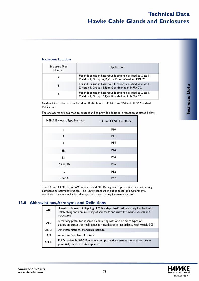
Further information can be found in NEMA Standard Publication 250 and UL 50 Standard Publication.
The enclosures are designed to protect and to provide additional protection as stated below: -
The IEC and CENELEC 60529 Standards and NEMA degrees of protection can not be fully compared as equivalent ratings. The NEMA Standard includes tests for environmental conditions such as mechanical damage, corrosion, rusting, ice formation, etc.
Hazardous Locations
Enclosure Type Number
Application
For indoor use in hazardous locations classified as Class II, Division 1, Groups E, F, or G as defined in NFPA 70.
8
For indoor use in hazardous locations classified as Class II, Division 1, Groups E, F, or G as defined in NFPA 70.
9
For indoor use in hazardous locations classified as Class I, Division 1, Groups A, B, C, or D as defined in NFPA 70.7
American National Standards InstituteANSI
American Petroleum InstituteAPI
A marking prefix for apparatus complying with one or more types of explosion protection techniques for installation in accordance with Article 505 AEx
EU Directive 94/9/EC Equipment and protective systems intended for use in potentially explosive atmospheres
ATEX
American Bureau of Shipping. ABS is a ship classification society involved with establishing and administering of standards and rules for marine vessels and structures.
ABS
NEMA Enclosure Type Number IEC and CENELEC 60529
IP101
IP112
IP543
IP143R
IP543S
IP564 and 4X
IP525
IP676 and 6P
13.0Abbreviations, Acronyms and Definitions
HWK21 Feb '04International75
Smarter productswww.ehawke.com
Tech
nica
l Dat
a
Hawke Cable Glands and EnclosuresTechnical Data
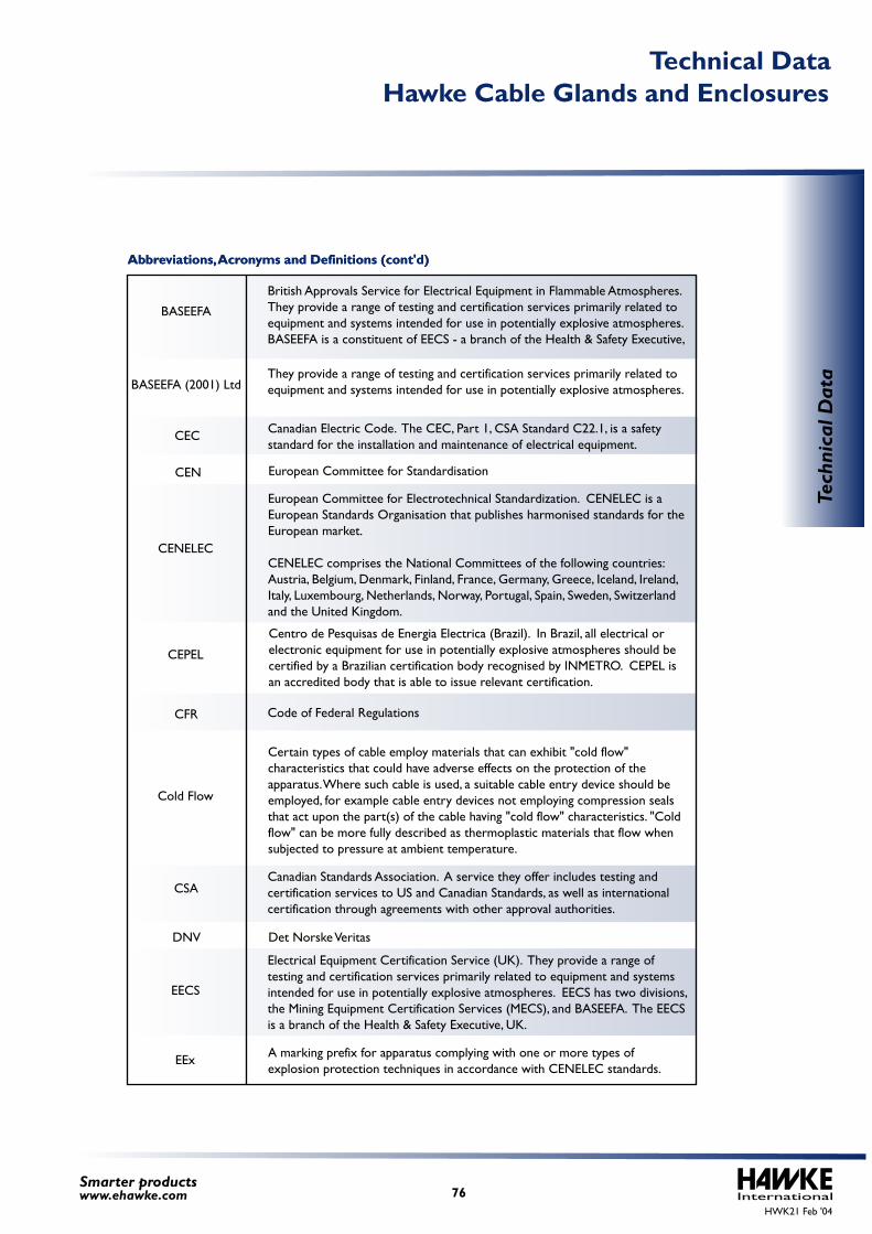
Abbreviations, Acronyms and Definitions (cont'd)
Code of Federal RegulationsCFR
Certain types of cable employ materials that can exhibit "cold flow" characteristics that could have adverse effects on the protection of the apparatus. Where such cable is used, a suitable cable entry device should be employed, for example cable entry devices not employing compression seals that act upon the part(s) of the cable having "cold flow" characteristics. "Cold flow" can be more fully described as thermoplastic materials that flow when subjected to pressure at ambient temperature.
Cold Flow
A marking prefix for apparatus complying with one or more types of explosion protection techniques in accordance with CENELEC standards.
EEx
Det Norske VeritasDNV
Centro de Pesquisas de Energia Electrica (Brazil). In Brazil, all electrical or electronic equipment for use in potentially explosive atmospheres should be certified by a Brazilian certification body recognised by INMETRO. CEPEL is an accredited body that is able to issue relevant certification.
CEPEL
Canadian Standards Association. A service they offer includes testing and certification services to US and Canadian Standards, as well as international certification through agreements with other approval authorities.
CSA
Electrical Equipment Certification Service (UK). They provide a range of testing and certification services primarily related to equipment and systems intended for use in potentially explosive atmospheres. EECS has two divisions, the Mining Equipment Certification Services (MECS), and BASEEFA. The EECS is a branch of the Health & Safety Executive, UK.
They provide a range of testing and certification services primarily related to equipment and systems intended for use in potentially explosive atmospheres.
EECS
European Committee for Electrotechnical Standardization. CENELEC is a European Standards Organisation that publishes harmonised standards for the European market.
CENELEC comprises the National Committees of the following countries: Austria, Belgium, Denmark, Finland, France, Germany, Greece, Iceland, Ireland, Italy, Luxembourg, Netherlands, Norway, Portugal, Spain, Sweden, Switzerland and the United Kingdom.
CENELEC
Canadian Electric Code. The CEC, Part 1, CSA Standard C22.1, is a safety standard for the installation and maintenance of electrical equipment.
CEC
European Committee for StandardisationCEN
British Approvals Service for Electrical Equipment in Flammable Atmospheres. They provide a range of testing and certification services primarily related to equipment and systems intended for use in potentially explosive atmospheres. BASEEFA is a constituent of EECS - a branch of the Health & Safety Executive,
BASEEFA
BASEEFA (2001) Ltd
HWK21 Feb '04International76
Smarter productswww.ehawke.com
Tech
nica
l Dat
a
Hawke Cable Glands and EnclosuresTechnical Data
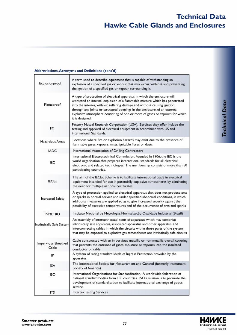
Abbreviations, Acronyms and Definitions (cont'd)
International Electrotechnical Commission. Founded in 1906, the IEC is the world organisation that prepares international standards for all electrical, electronic and related technologies. The membership consists of more than 50 participating countries.
IEC
A type of protection applied to electrical apparatus that does not produce arcs or sparks in normal service and under specified abnormal conditions, in which additional measures are applied so as to give increased security against the possibility of excessive temperatures and of the occurrence of arcs and sparks
Increased Safety
An assembly of interconnected items of apparatus which may comprise intrinsically safe apparatus, associated apparatus and other apparatus, and interconnecting cables in which the circuits within those parts of the system that may be exposed to explosive gas atmospheres are intrinsically safe circuits
Intrinsically Safe System
A system of rating standard levels of Ingress Protection provided by the apparatus.
IP
Cable constructed with an impervious metallic or non-metallic overall covering that prevents the entrance of gases, moisture or vapours into the insulated conductor or cable
Impervious Sheathed Cable
The aim of the IECEx Scheme is to facilitate international trade in electrical equipment intended for use in potentially explosive atmospheres by eliminating the need for multiple national certificates.
IECEx
Instituto Nacional de Metrologia, Normalizacão Qualidade Industrial (Brazil)INMETRO
The International Society for Measurement and Control (formerly Instrument Society of America)
ISA
Intertek Testing ServicesITS
International Organisations for Standardisation. A worldwide federation of national standard bodies from 130 countries. ISO's mission is to promote the development of standardisation to facilitate international exchange of goods service.
ISO
International Association of Drilling ContractorsIADC
Locations where fire or explosion hazards may exist due to the presence of flammable gases, vapours, mists, ignitable fibres or dusts
Hazardous Areas
A type of protection of electrical apparatus in which the enclosure will withstand an internal explosion of a flammable mixture which has penetrated into the interior, without suffering damage and without causing ignition, through any joints or structural openings in the enclosure, of an external explosive atmosphere consisting of one or more of gases or vapours for which it is designed.
Flameproof
Factory Mutual Research Corporation (USA). Services they offer include the testing and approval of electrical equipment in accordance with US and international Standards.
FM
A term used to describe equipment that is capable of withstanding an explosion of a specified gas or vapour that may occur within it and preventing the ignition of a specified gas or vapour surrounding it.
Explosionproof
HWK21 Feb '04International77
Smarter productswww.ehawke.com
Tech
nica
l Dat
a
Hawke Cable Glands and EnclosuresTechnical Data
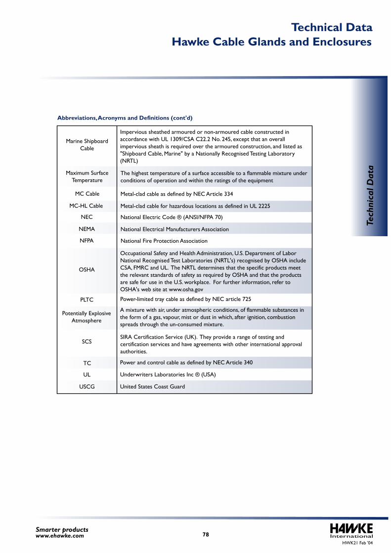
Abbreviations, Acronyms and Definitions (cont'd)
A mixture with air, under atmospheric conditions, of flammable substances in the form of a gas, vapour, mist or dust in which, after ignition, combustion spreads through the un-consumed mixture.
Potentially Explosive Atmosphere
Power and control cable as defined by NEC Article 340TC
United States Coast GuardUSCG
Underwriters Laboratories Inc ® (USA)UL
Power-limited tray cable as defined by NEC article 725PLTC
SIRA Certification Service (UK). They provide a range of testing and certification services and have agreements with other international approval authorities.
SCS
Occupational Safety and Health Administration, U.S. Department of LaborNational Recognised Test Laboratories (NRTL's) recognised by OSHA include CSA, FMRC and UL. The NRTL determines that the specific products meet the relevant standards of safety as required by OSHA and that the products are safe for use in the U.S. workplace. For further information, refer to OSHA's web site at www.osha.gov
OSHA
Metal-clad cable for hazardous locations as defined in UL 2225MC-HL Cable
National Electrical Manufacturers AssociationNEMA
Metal-clad cable as defined by NEC Article 334MC Cable
National Electric Code ® (ANSI/NFPA 70)NEC
National Fire Protection AssociationNFPA
The highest temperature of a surface accessible to a flammable mixture under conditions of operation and within the ratings of the equipment
Maximum Surface Temperature
Impervious sheathed armoured or non-armoured cable constructed in accordance with UL 1309/CSA C22.2 No. 245, except that an overall impervious sheath is required over the armoured construction, and listed as "Shipboard Cable, Marine" by a Nationally Recognised Testing Laboratory (NRTL)
Marine ShipboardCable
HWK21 Feb '04International78
Smarter productswww.ehawke.com
Tech
nica
l Dat
a
Hawke Cable Glands and EnclosuresTechnical Data

InternationalHWK21 Feb '04
Flameproof/Increased Safety and Industrial
79Smarter productswww.ehawke.com
Haw
ke C
able
Gla
nds
Hawke Cable Glands
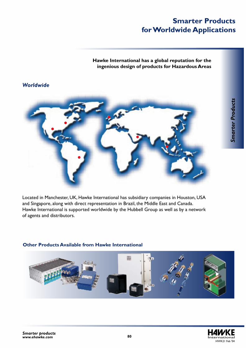
Other Products Available from Hawke International
International80Smarter productswww.ehawke.com
Smar
ter
Prod
ucts
Smarter Products for Worldwide Applications
HWK21 Feb '04
Worldwide
Located in Manchester, UK, Hawke International has subsidiary companies in Houston, USA and Singapore, along with direct representation in Brazil, the Middle East and Canada. Hawke International is supported worldwide by the Hubbell Group as well as by a network of agents and distributors.
Hawke International has a global reputation for theingenious design of products for Hazardous Areas

Smarter productswww.ehawke.com
Hawke international is a division ofHubbell Ltd.A member of the Hubbell Group of Companies.
Visit us at www.ehawke.com
Hawke Cable Glands LimitedOxford Street West,Ashton-under-Lyne,Lancashire OL7 0NA. UK.Sales: 0870 60 60 105Tel: +44 (0) 161 308 3611Fax: +44 (0) 161 308 5848E-mail: [email protected]
Hawke Cable Glands America L.C.600 Kenrick, Suite C-10,Houston, TX. 77060, USATel: +1 (281) 445 7400Wats: (800) 354 9189Fax: +1 (281) 445 7404E-mail: [email protected]
Hawke Asia-Pacific Pte Ltd130 Joo Seng Road, #03-02Olivine BuildingSingapore 368357 Tel: 00 65 6282 2242 Fax: 00 65 6284 4244 E-mail: [email protected] HWK21 Feb '04
To the best of our knowledge the information contained in this leaflet, is accurate at the time of going to print and the company reserves the right to improve or modify any product illustrated without notification. The company is unable to accept liability for any inaccuracies, errors or omissions that may exist. It is the customer's responsibility to ensure that the product is suitable for their application.
All copyright reserved-Hubbell Ltd. This document and all copyright therein is the property of: Hawke International a division of of Hubbell Ltd (A member of the Hubbell Group of Companies). Copyright Condition: This document shall be used only for the purpose for which it is provided and no reproduction or publication of the document may be made and no article may be manufactured or assembled in accordance with information contained in the document without prior written consent of the owner.
International
Agent/Distributor
Top Related