


Languages
Pages
Legal

Universidade de Aveiro2012
Departamento de Electrónica, Telecomunicações e Informática
Virgílio António Ferro Bento
SWORD – Um dispositivo vibratório vestível para uma reabilitação mais eficiente em doentes com AVC SWORD – An intelligent vibratory wearable device to improve rehabilitation in stroke patients
Tese apresentada à Universidade de Aveiro para cumprimento dos requisitos necessários à obtenção do grau de Doutor em Engenharia Electrotécnica, realizada sob a orientação científica do Doutor João Paulo Trigueiros da Silva Cunha, Professor Associado com Agregação da Faculdade de Engenharia da Universidade do Porto e sob a coorientação do Doutor José Maria Amaral Fernandes, Professor Auxiliar do Departamento de Electrónica, Telecomunicações e Informática da Universidade de Aveiro
Apoio financeiro da FCT e do FSE no âmbito do Quadro de Referência Estratégico Nacional.

Dedico este trabalho à minha avó Rosa e ao meu irmão Pedro. Obrigado.

o júri
presidente Doutora Maria Celeste da Silva do Carmo Professora Catedrática da Universidade de Aveiro.
Doutor Nuno Jorge Carvalho de Sousa Professor Catedrático do Instituto de Ciências da Vida e da Saúde da Escola de Ciências da Universidade do Minho.
Doutor João Paulo Trigueiros da Silva Cunha Professor Associado com Agregação da Faculdade de Engenharia de Universidade do Porto. (Orientador)
Doutor Miguel Velhote Correia Professor Auxiliar da Faculdade de Engenharia da Universidade do Porto.
Doutor José Maria Amaral Fernandes Professor Auxiliar da Universidade de Aveiro. (Coorientador)
Doutor Nuno Sérgio Mendes Dias Professor Adjunto da Escola Superior de Tecnologia do Instituto Politécnico do Cávado e do Ave.

agradecimentos
Aos meus pais, por terem tirado todos os espinhos do meu caminho e me terem mostrado de forma directa que mesmo a mais difícil luta vale sempre a pena no fim.
Ao meu irmão Pedro, parte essencial da minha felicidade.
À Claudia Barroso, por ter acreditado em mim e ter compreendido as inúmeras “faltas de tempo”. Sempre presente em todas as etapas deste trabalho, foi uma fonte contínua de inspiração.
Ao meu tio Hernâni Bento, pela motivação que me empresta e pelo seu exemplo de empreendorismo.
Ao Prof. Doutor João Paulo Cunha, na qualidade de orientador do trabalho de doutoramento, pelo estimulante ambiente de trabalho proporcionado, elevado grau de exigência demonstrado e confiança na minha independência.
Ao Dr. Vítor Cruz, por ser um brilhante complemento aos meus conhecimentos. Cada passo dado foi sempre o resultado de uma troca de ideias que resolviam problemas presentes e descobriam sistemas futuros. A sua extraordinária capacidade de perceber o que é a tecnologia e qual o seu potencial marca este projecto.
Ao David Ribeiro, meu parceiro no desenvolvimento do sistema de quantificação de movimento. A excelência de hardware que constitui o sistema de quantificação de movimento a ele se deve.
Ao Márcio Colunas, por ter desenvolvido o sistema de análise de resultados para o SWORD na sua componente de Tele-Reabilitação. Por ter acreditado neste projecto e abdicado das suas férias. Sem ele, o prémio obtido em Boston tinha sido uma miragem.
Ao Francisco Coelho e David Barroso, sempre presentes nesta caminhada.
Ao Aquiles, por ter sido um companheiro nos vários momentos Eureka que galvanizaram o desenvolvimento do SWORD.
A todos os pacientes que testaram os diversos sistemas desenvolvidos, um especial obrigado.
Ao apoio financeiro concedido pela Fundação para a Ciência e Tecnologia na forma do projecto de investigação PTDC/SAU-NEU/102075/2008.
À Universidade de Aveiro e ao Instituto de Engenharia Electrónica e Telemática de Aveiro, um local perfeito para criar.

palavras-chave
AVC, dispositivos de reabilitação, interface háptica, sistemas de quantificação de movimento, estímulo vibratório, tele-reabilitação, avaliação da função motora.
resumo
Anualmente ocorrem cerca de 16 milhões AVCs em todo o mundo. Cerca demetade dos sobreviventes irá apresentar défice motor que necessitará dereabilitação na janela dos 3 aos 6 meses depois do AVC. Nos paísesdesenvolvidos, é estimado que os custos com AVCs representem cerca de0.27% do Produto Interno Bruto de cada País. Esta situação implica umenorme peso social e financeiro. Paradoxalmente a esta situação, é aceite nacomunidade médica a necessidade de serviços de reabilitação motora maisintensivos e centrados no doente. Na revisão do estado da arte, demonstra-se o arquétipo que relacionametodologias terapêuticas mais intensivas com uma mais proficientereabilitação motora do doente. Revelam-se também as falhas nas soluçõestecnológicas existentes que apresentam uma elevada complexidade e custoassociado de aquisição e manutenção. Desta forma, a pergunta que suporta o trabalho de doutoramento seguidoinquire a possibilidade de criar um novo dispositivo de simples utilização e debaixo custo, capaz de apoiar uma recuperação motora mais eficiente de umdoente após AVC, aliando intensidade com determinação da correcção dosmovimentos realizados relativamente aos prescritos. Propondo o uso do estímulo vibratório como uma ferramenta proprioceptiva deintervenção terapêutica a usar no novo dispositivo, demonstra-se atolerabilidade a este tipo de estímulos através do teste duma primeira versãodo sistema apenas com a componente de estimulação num primeiro grupo de5 doentes. Esta fase validará o subsequente desenvolvimento do sistemaSWORD. Projectando o sistema SWORD como uma ferramenta complementar queintegra as componentes de avaliação motora e intervenção proprioceptiva porestimulação, é descrito o desenvolvimento da componente de quantificação demovimento que o integra. São apresentadas as diversas soluções estudadas eo algoritmo que representa a implementação final baseada na fusão sensorialdas medidas provenientes de três sensores: acelerómetro, giroscópio emagnetómetro. O teste ao sistema SWORD, quando comparado com ométodo de reabilitação tradicional, mostrou um ganho considerável deintensidade e qualidade na execução motora para 4 dos 5 doentes testadosnum segundo grupo experimental. É mostrada a versatilidade do sistema SWORD através do desenvolvimento domódulo de Tele-Reabilitação que complementa a componente de quantificaçãode movimento com uma interface gráfica de feedback e uma ferramenta deanálise remota da evolução motora do doente. Finalmente, a partir da componente de quantificação de movimento, foi aindadesenvolvida uma versão para avaliação motora automatizada, implementadaa partir da escala WMFT, que visa retirar o factor subjectivo da avaliaçãohumana presente nas escalas de avaliação motora usadas em Neurologia.Esta versão do sistema foi testada num terceiro grupo experimental de cincodoentes.

keywords
stroke,rehabilitation devices, haptic interface, motion capture systems, vibratory stimuli, tele-rehabilitation, motor function evaluation
abstract
About 16 million first ever-strokes occur worldwide every year. Half of strokesurvivors are left with some degree of physical impairment that needsrehabilitation in the 3 to 6 month after-stroke time window. This situation impliesa high economic and social burden. In developed countries, stroke cost isestimated to represent an average of 0.27% of each country’s gross domesticproduct. Paradoxically, it is accepted in the medical community the need formore intensive and patient-centered rehabilitation services. In the state of art review, it is demonstrated the archetype that relates theintensity on rehabilitation with a proficient motor recovery of the patient.Additionally, it is shown that the major pitfalls in current technological solutionsin the field of motor rehabilitation are due to their intrinsic complexity andassociated cost. Given this state of the art, the research question that supports this thesis,inquiries the possibility of creating a novel low-cost device targeted at the motorrehabilitation of stroke patients, capable of providing a more efficient treatmentthrough enabling higher intensity and automated determination of thecorrectness of the movements performed by the recovering patient. The validity of the vibratory stimulus is presented from an historic andneurophysiologic point of view. Furthermore, a state of art review of motioncapture systems is presented. Intending the use of the vibratory stimulus as a proprioceptive therapeutic toolto be integrated in the new device, it is demonstrated the tolerability of thestimulus from the experimental test of a first version of the device, incorporatingthe stimulation component, in a first group of five patients. Projecting the SWORD device as a tool that combines both features of motorfunction evaluation with proprioceptive intervention through vibratorystimulation, it is described the development of the motion capture component.Several solutions were studied and the final algorithm, based on the sensoryfusion of the measures from three sensors (accelerometer, gyroscope andmagnetometer), is described in detail. The experimental test of the SWORD system on a second group of patientsshowed that, when compared with a typical treatment, it is capable of providinga more intensive intervention and with a higher quality in 4 out of 5 patients. To demonstrate the versatility of the SWORD system, it was developed thetele-rehabilitation module that complements the motion capture component witha graphical feedback interface and a remote tool for the clinician to evaluate theperformance of the patient through out the time he uses the system in his homeor any other remote environment. Finally, from the motion capture component, a motor function evaluationversion of the system was deployed. Implemented from the WMFT scale, itaims to eliminate the human subjectivity present in the traditional evaluationscales used in the neurology medical area. This system was evaluated on athird group of five patients.

viii
Contents
Contents ..................................................................................................................... viii
List of Figures .............................................................................................................. xi
List of Tables .......................................................................................................... xviii
List of Acronyms ....................................................................................................... xix
Chapter 1
Introduction ................................................................................................................... 1
1.1Motivation ............................................................................................................ 2
1.2Objectives ............................................................................................................. 3
1.3Thesis Organization ............................................................................................ 4
1.3.1Thesis Roadmap ........................................................................................... 4
1.3.2Chapter Descriptions ................................................................................... 4
1.4Original contributions and achievements ....................................................... 5
Chapter 2
State of the art ................................................................................................................ 8
2.1 Motor Recovery after Stroke ............................................................................. 9
2.1.2 Technology‐based interventions ................................................................ 9
2.1.3 Recommendations for treatment .............................................................. 10
2.2 The vibratory stimulus ..................................................................................... 12
2.2.1 Historical perspective ................................................................................ 12
2.2.2 Background physiopathological principles ............................................ 16
2.2.3 Stimulus‐based neurorehabilitation approaches ................................... 18
2.2.4 Vibration as a stimulus for cortical activation ....................................... 20
2.3 Human motion analysis ................................................................................... 24
2.3.1 Historical perspective ................................................................................ 24

ix
2.3.2 Motion capture technology ....................................................................... 27
2.4 Summary ............................................................................................................ 33
Chapter 3
The Vibratory stimulus as a neurorehabilitation tool for stroke patients .......... 35
3.1 Methods .............................................................................................................. 36
3.1.1 Stimulation device ...................................................................................... 36
3.1.2 Patient selection .......................................................................................... 44
3.1.3 Tolerability test design and procedures .................................................. 45
3.1.4 Specific measures used .............................................................................. 46
3.2 Results ................................................................................................................. 46
3.3 Discussion .......................................................................................................... 49
3.4 Conclusion ......................................................................................................... 50
Chapter 4
The SWORD device .................................................................................................... 51
4.1 Introduction ....................................................................................................... 52
4.2 Methods .............................................................................................................. 55
4.2.1 Intervention definition .............................................................................. 56
4.2.2 Movement Quantification System ........................................................... 59
4.2.3. Stimulation System ................................................................................... 73
4.2.4. System Architecture .................................................................................. 75
4.2.5 Tele‐Rehabilitation Module ...................................................................... 82
4.3 Results ................................................................................................................. 88
4.3.1 Experimental Setup .................................................................................... 88
4.3.2 Comparing the two treatments (Typical and SWORD) ........................ 92
4.4 Discussion .......................................................................................................... 98
4.5 Conclusion ......................................................................................................... 99


x
Chapter 5
A movement quantification system capable of automatic evaluation of upper
limb motor function ................................................................................................. 101
5.1 Introduction ..................................................................................................... 103
5.2 Methods ............................................................................................................ 104
5.2.1 WMFT Description ................................................................................... 104
5.2.2 Proposed System ...................................................................................... 108
5.2.3 Subjects ...................................................................................................... 116
5.2.4 Procedure ................................................................................................... 116
5.3 Results ............................................................................................................... 116
5.3.1 Performance time ..................................................................................... 116
5.3.2 Functional Ability Score .......................................................................... 117
5.4. Discussion ....................................................................................................... 122
5.5 Conclusions ...................................................................................................... 123
Chapter 6
Conclusion and Future work .................................................................................. 125
Bibliography ............................................................................................................. 129

xi
List of Figures
Figure 1 ‐ Roadmap. ........................................................................................................... 4
Figure 2 ‐ Hand function training device “Rehab‐Digit” [18] .................................... 10
Figure 3 ‐ Review of the interventions designed to improve upper‐limb motor
function after stroke in terms of the intervention category, number of
participants recruited and the 95% confidence interval for the effect of the
intervention on the outcome measure. Results show that interventions
based on the constraint‐induced movement of the arm are the ones that
show a higher proficiency. The most common outcome measures used in
the evaluation of motor improvement of the upper‐limb where the action
research arm test, motor assessment scale and the Fugl‐Meyer scale
(adapted from [21]). .............................................................................................. 11
Figure 4 ‐ Pattern of functional motor recovery for a patient after Stroke onset
subjected to an effective therapy (adapted from [13]) ..................................... 12
Figure 5 ‐ Vibratory chair designed by Charcot and used at the Salpêtière Hospital
to treat patients with Parkinson’s disease [25]. ................................................ 13
Figure 6 ‐ Whole‐Body vibration experimental setup (standing posture of the
subject on the Galileo 900 Vibratory platform) [28] ......................................... 14
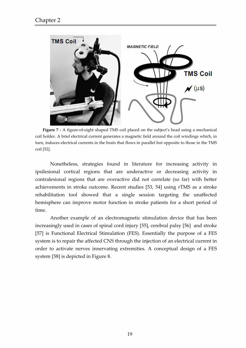
Figure 7 ‐ A figure‐of‐eight shaped TMS coil placed on the subject’s head using a
mechanical coil holder. A brief electrical current (μs) generates a magnetic
field around the coil windings which, in turn, induces electrical currents in
the brain that flows in parallel but opposite to those in the TMS coil [52]. . 19
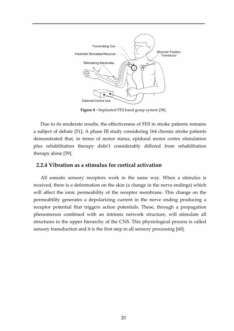
Figure 8 ‐ Implanted FES hand grasp system [58]. ...................................................... 20
Figure 9 ‐ General organization of the somatic sensory system. Red line shows the
course of the mechanosensory information from the receptor endings to the
brain [60]. ............................................................................................................... 21
Figure 10 ‐ Adaptation of the mechanoreceptors in the presence of an ongoing
stimulus. Rapidly adapting receptors respond only at the onset of
stimulation [60]. .................................................................................................... 22

xii
Figure 11 ‐ Sensitivity discrimination of the body surface in terms of the minimum
distance (in mm) required to sense two stimulus, applied in simultaneous,
as distinct. (adapted from [60] after the work of Weinstein [61]). ................. 23
Figure 12 ‐ Activation maps for the individual subjects with the least, median and
most significant cluster activation in the S1, S2 and thalamic areas (from a
total sample of five subjects) (adapted from [34]). ........................................... 24
Figure 13 ‐ Vertical component of the ground reaction force as recorded by Carlet
using the pressure sensors at the sole of the subject’s shoe [70]. ................... 25
Figure 14 ‐ Chronophotograph recordings of a soldier walking [71]. ...................... 26
Figure 15 ‐ Vicon motion capture system used in the kinematic analysis of the golf
swing [81]. .............................................................................................................. 28
Figure 16 ‐ Gypsy‐7® exo‐skeleton motion capture system [83] ................................ 29
Figure 17 ‐ Schematic of a micro‐electromechanical vibrating gyroscope [86]. ...... 30
Figure 18 ‐ Simplified model of a spring‐mass system, displaying the effect of the
imposed acceleration (a) on the displacement (xdis) of the mass (m). This
model is analogous to the inner structure of a single‐axis micro‐
electromechanical accelerometer system. ......................................................... 31
Figure 19 ‐ Diagram showing the major topics covered in this state of art review.
The area of each circle is respective to the number of citations for each topic.
Only topics with five or more citation were individualized. ......................... 34
Figure 20 ‐ System configuration. ................................................................................... 37
Figure 21 ‐Dimensional specification of the vibration motor used (dimensions in
millimeters). Adapted from [117]. ...................................................................... 38
Figure 22 ‐ Peformance characteristics for the vibration motor selected (adapted
from [117]). ............................................................................................................. 40
Figure 23 ‐ Description of the stimulation device in terms of its main components.
The configuration of the stimulus type is selected from the definition of the
stimulus amplitude and dynamics. ................................................................... 41
Figure 24 ‐ LED display of the selected stimulus amplitude. .................................... 42
Figure 25 ‐ LED display of the selected stimulus dynamics. ..................................... 42
Figure 26 ‐ Display of the special case that defines the automatic mode of use. .... 43
Figure 27 ‐ Tolerability test performed on a stroke patient with an assortment of
vibratory stimuli, delivered at the wrist joint. .................................................. 45
Figure 28 ‐Tolerability test performed on a stroke patient with an assortment of
vibratory stimuli, delivered at the ankle joint. ................................................. 46

xiii
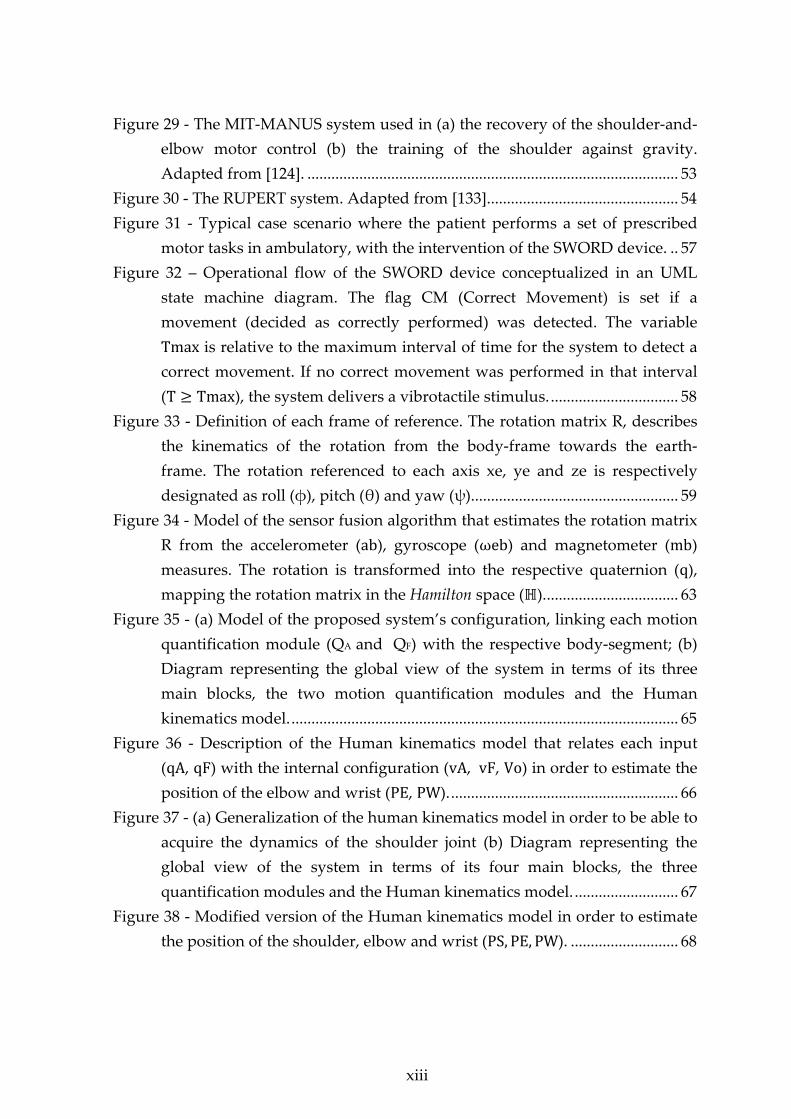
Figure 29 ‐ The MIT‐MANUS system used in (a) the recovery of the shoulder‐and‐
elbow motor control (b) the training of the shoulder against gravity.
Adapted from [124]. ............................................................................................. 53
Figure 30 ‐ The RUPERT system. Adapted from [133]. ............................................... 54
Figure 31 ‐ Typical case scenario where the patient performs a set of prescribed
motor tasks in ambulatory, with the intervention of the SWORD device. .. 57
Figure 32 – Operational flow of the SWORD device conceptualized in an UML
state machine diagram. The flag CM (Correct Movement) is set if a
movement (decided as correctly performed) was detected. The variable
Tmax is relative to the maximum interval of time for the system to detect a
correct movement. If no correct movement was performed in that interval
(T Tmax), the system delivers a vibrotactile stimulus. ................................ 58
Figure 33 ‐ Definition of each frame of reference. The rotation matrix R, describes
the kinematics of the rotation from the body‐frame towards the earth‐
frame. The rotation referenced to each axis xe, ye and ze is respectively
designated as roll (φ), pitch (θ) and yaw (ψ). ................................................... 59
Figure 34 ‐ Model of the sensor fusion algorithm that estimates the rotation matrix
R from the accelerometer (ab), gyroscope (ωeb) and magnetometer (mb)
measures. The rotation is transformed into the respective quaternion (q),
mapping the rotation matrix in the Hamilton space ( ). ................................. 63
Figure 35 ‐ (a) Model of the proposed system’s configuration, linking each motion
quantification module (QA and QF) with the respective body‐segment; (b)
Diagram representing the global view of the system in terms of its three
main blocks, the two motion quantification modules and the Human
kinematics model. ................................................................................................. 65
Figure 36 ‐ Description of the Human kinematics model that relates each input
(qA, qF) with the internal configuration (vA, vF, Vo) in order to estimate the
position of the elbow and wrist (PE, PW). ......................................................... 66
Figure 37 ‐ (a) Generalization of the human kinematics model in order to be able to
acquire the dynamics of the shoulder joint (b) Diagram representing the
global view of the system in terms of its four main blocks, the three
quantification modules and the Human kinematics model. .......................... 67
Figure 38 ‐ Modified version of the Human kinematics model in order to estimate
the position of the shoulder, elbow and wrist (PS, PE, PW). ........................... 68

xiv
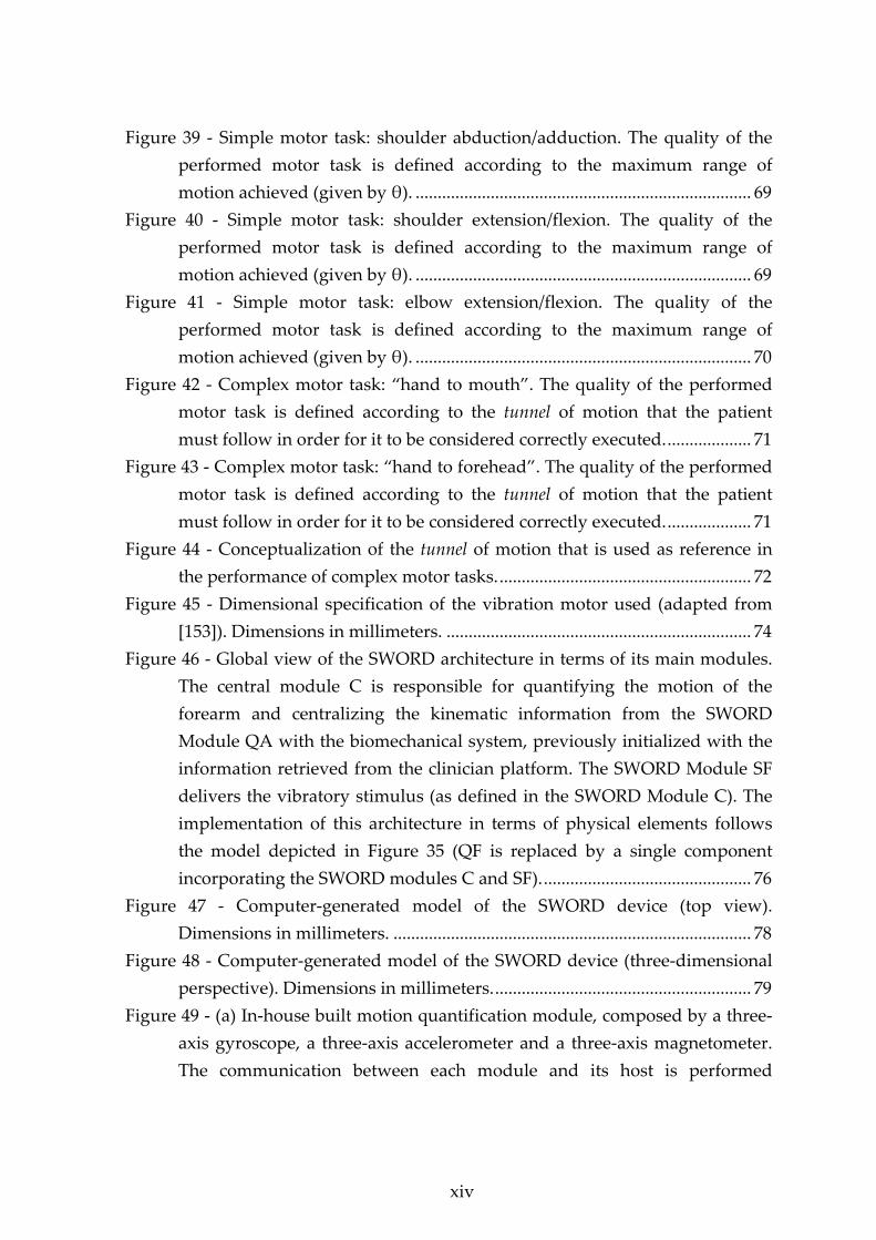
Figure 39 ‐ Simple motor task: shoulder abduction/adduction. The quality of the
performed motor task is defined according to the maximum range of
motion achieved (given by θ). ............................................................................ 69
Figure 40 ‐ Simple motor task: shoulder extension/flexion. The quality of the
performed motor task is defined according to the maximum range of
motion achieved (given by θ). ............................................................................ 69
Figure 41 ‐ Simple motor task: elbow extension/flexion. The quality of the
performed motor task is defined according to the maximum range of
motion achieved (given by θ). ............................................................................ 70
Figure 42 ‐ Complex motor task: “hand to mouth”. The quality of the performed
motor task is defined according to the tunnel of motion that the patient
must follow in order for it to be considered correctly executed. ................... 71
Figure 43 ‐ Complex motor task: “hand to forehead”. The quality of the performed
motor task is defined according to the tunnel of motion that the patient
must follow in order for it to be considered correctly executed. ................... 71
Figure 44 ‐ Conceptualization of the tunnel of motion that is used as reference in
the performance of complex motor tasks. ......................................................... 72
Figure 45 ‐ Dimensional specification of the vibration motor used (adapted from
[153]). Dimensions in millimeters. ..................................................................... 74
Figure 46 ‐ Global view of the SWORD architecture in terms of its main modules.
The central module C is responsible for quantifying the motion of the
forearm and centralizing the kinematic information from the SWORD
Module QA with the biomechanical system, previously initialized with the
information retrieved from the clinician platform. The SWORD Module SF
delivers the vibratory stimulus (as defined in the SWORD Module C). The
implementation of this architecture in terms of physical elements follows
the model depicted in Figure 35 (QF is replaced by a single component
incorporating the SWORD modules C and SF). ............................................... 76
Figure 47 ‐ Computer‐generated model of the SWORD device (top view).
Dimensions in millimeters. ................................................................................. 78
Figure 48 ‐ Computer‐generated model of the SWORD device (three‐dimensional
perspective). Dimensions in millimeters. .......................................................... 79
Figure 49 ‐ (a) In‐house built motion quantification module, composed by a three‐
axis gyroscope, a three‐axis accelerometer and a three‐axis magnetometer.
The communication between each module and its host is performed


xv
through a Bluetooth connection (b) Depiction of the SWORD device in its
wearable form, placed at the forearm and arm of a Stroke patient. .............. 80
Figure 50 ‐ Demonstration of the scalability of the SWORD device. The
implementation of this architecture in terms of physical elements follows
the model depicted in Figure 37 (QF is replaced by a single component
incorporating the SWORD modules C and SF). ............................................... 81
Figure 51 ‐ Conceptual definition of the Human Kinematics Model for the lower
limb. The reference point Vo is located at the hip‐joint. Three quantification
modules (QFe,QT and QFo), estimate the orientation of the Femur, Tibia
and Foot segments (generic consideration). The output of the model is the
three‐dimensional position of the Knee (PK), Ankle (PA) and Foot extremity
(PF). ......................................................................................................................... 82
Figure 52 ‐ Global architecture of the SWORD Tele‐Rehabilitation system. ........... 83
Figure 53 – Graphic interface for simple motor executions: Airplane game
developed to train the mobility and range of movements of the patients’
upper limb. In this game, the movement of the plane is defined in one‐
dimension (up/down) and controlled by θ as defined in the motor task of
shoulder extension/flexion (as depicted in Figure 41). ................................... 85
Figure 54 ‐ Graphic interface for complex motor executions: Console that displays
the movement performed by the patient in the sagittal and frontal planes of
view. Each motor task presents in the screen graphic cues and alerts the
patient if the movement is being badly performed. This console was
designed to train complex movements using the tunnel of motion as
reference. Rehabilitation scores regarding performance, correct/wrong
executions and level of difficulty are sent to a central server from where the
clinician’s host retrieves the data for analysis. ................................................. 86
Figure 55 ‐ Each clinician has a personal login that relates him to a list of his
patients (www.theprojectsword.com). .............................................................. 87
Figure 56 ‐ Analytics of the clinician’s web‐based application, where the clinician
evaluates the quality and intensity of the rehabilitation therapy of the
patient in ambulatory. .......................................................................................... 88
Figure 57 ‐ Shoulder extension/flexion performed with the SWORD device in
autonomous mode. (a) Initial position (θ 0°) (b) Final position (θ 90°)
................................................................................................................................. 89

xvi
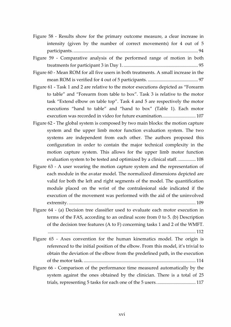
Figure 58 ‐ Results show for the primary outcome measure, a clear increase in
intensity (given by the number of correct movements) for 4 out of 5
participants. ........................................................................................................... 94
Figure 59 ‐ Comparative analysis of the performed range of motion in both
treatments for participant 3 in Day 1. ................................................................ 95
Figure 60 ‐ Mean ROM for all five users in both treatments. A small increase in the
mean ROM is verified for 4 out of 5 participants. ........................................... 97
Figure 61 ‐ Task 1 and 2 are relative to the motor executions depicted as “Forearm
to table” and “Forearm from table to box”. Task 3 is relative to the motor
task “Extend elbow on table top”. Task 4 and 5 are respectively the motor
executions “hand to table” and “hand to box” (Table 1). Each motor
execution was recorded in video for future examination. ............................ 107
Figure 62 ‐ The global system is composed by two main blocks: the motion capture
system and the upper limb motor function evaluation system. The two
systems are independent from each other. The authors proposed this
configuration in order to contain the major technical complexity in the
motion capture system. This allows for the upper limb motor function
evaluation system to be tested and optimized by a clinical staff. ............... 108
Figure 63 ‐ A user wearing the motion capture system and the representation of
each module in the avatar model. The normalized dimensions depicted are
valid for both the left and right segments of the model. The quantification
module placed on the wrist of the contralesional side indicated if the
execution of the movement was performed with the aid of the uninvolved
extremity. ............................................................................................................. 109
Figure 64 ‐ (a) Decision tree classifier used to evaluate each motor execution in
terms of the FAS, according to an ordinal score from 0 to 5. (b) Description
of the decision tree features (A to F) concerning tasks 1 and 2 of the WMFT.
............................................................................................................................... 112
Figure 65 ‐ Axes convention for the human kinematics model. The origin is
referenced to the initial position of the elbow. From this model, it’s trivial to
obtain the deviation of the elbow from the predefined path, in the execution
of the motor task. ................................................................................................ 114
Figure 66 ‐ Comparison of the performance time measured automatically by the
system against the ones obtained by the clinician. There is a total of 25
trials, representing 5 tasks for each one of the 5 users. ................................. 117

xvii
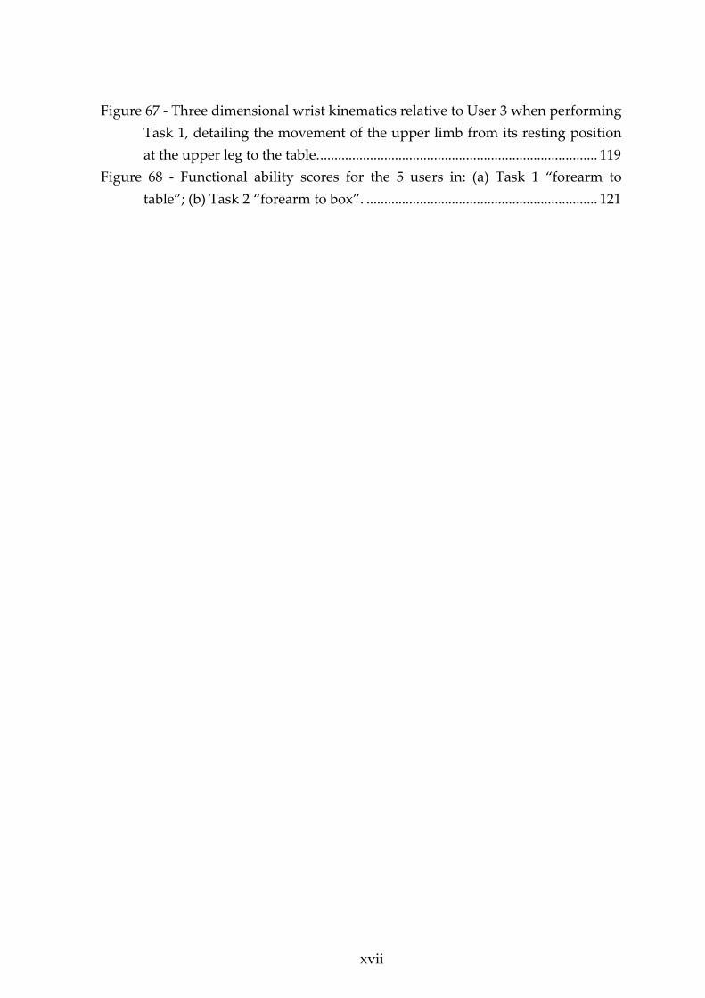
Figure 67 ‐ Three dimensional wrist kinematics relative to User 3 when performing
Task 1, detailing the movement of the upper limb from its resting position
at the upper leg to the table. .............................................................................. 119
Figure 68 ‐ Functional ability scores for the 5 users in: (a) Task 1 “forearm to
table”; (b) Task 2 “forearm to box”. ................................................................. 121

xviii
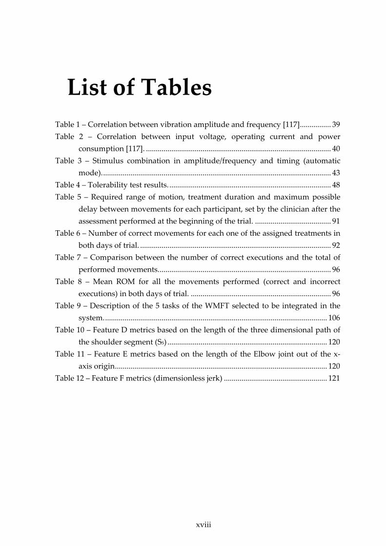
List of Tables
Table 1 – Correlation between vibration amplitude and frequency [117] ................ 39
Table 2 – Correlation between input voltage, operating current and power
consumption [117]. ............................................................................................... 40
Table 3 – Stimulus combination in amplitude/frequency and timing (automatic
mode). ..................................................................................................................... 43
Table 4 – Tolerability test results. ................................................................................... 48
Table 5 – Required range of motion, treatment duration and maximum possible
delay between movements for each participant, set by the clinician after the
assessment performed at the beginning of the trial. ....................................... 91
Table 6 – Number of correct movements for each one of the assigned treatments in
both days of trial. .................................................................................................. 92
Table 7 – Comparison between the number of correct executions and the total of
performed movements. ........................................................................................ 96
Table 8 – Mean ROM for all the movements performed (correct and incorrect
executions) in both days of trial. ........................................................................ 96
Table 9 – Description of the 5 tasks of the WMFT selected to be integrated in the
system. .................................................................................................................. 106
Table 10 – Feature D metrics based on the length of the three dimensional path of
the shoulder segment (SS) .................................................................................. 120
Table 11 – Feature E metrics based on the length of the Elbow joint out of the x‐
axis origin ............................................................................................................. 120
Table 12 – Feature F metrics (dimensionless jerk) ..................................................... 121


xix
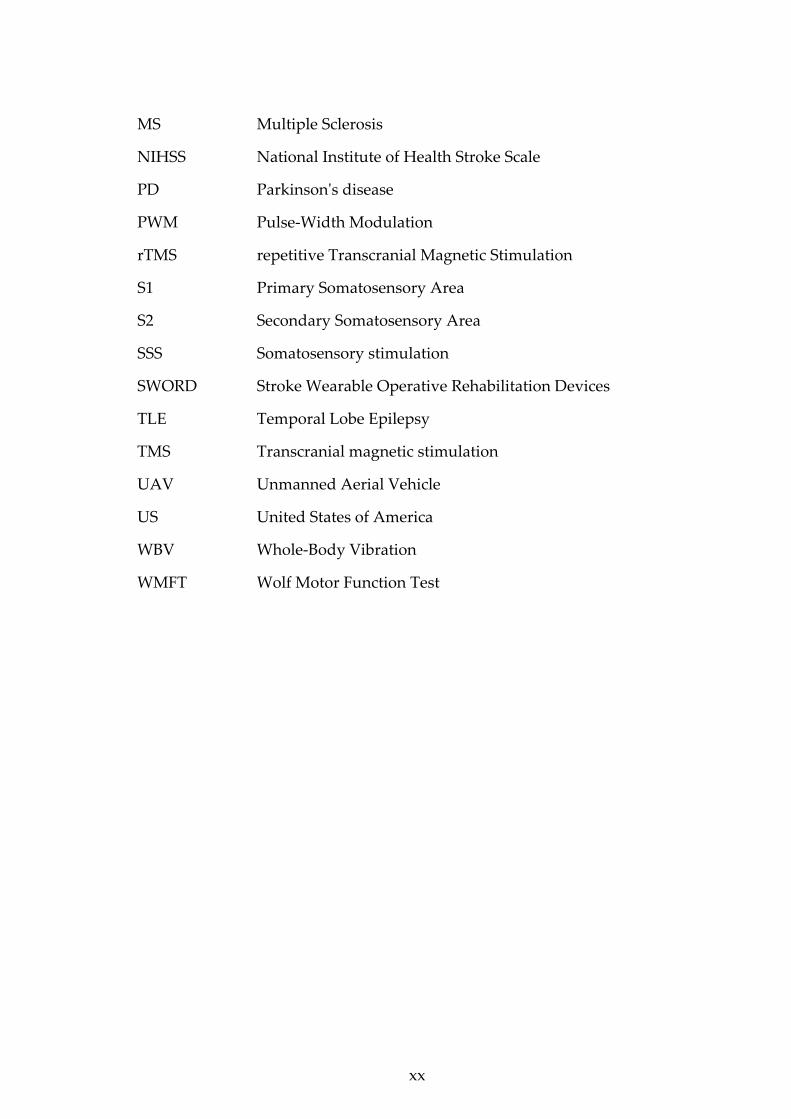
List of Acronyms
ADAPT Adaptive and Automatic Presentation of Tasks
ARAT Action Research Arm Test
CM Correct Movement
CNS Central Nervous System
DOF Degree of Freedom
EMG Electromyography
ERM Eccentric Rotating Mass
FES Functional Electric Stimulation
FMA Fugl‐Meyer Assessment
fMRI Functional Magnetic Resonance Imaging
FVS Functional Vibratory Stimulation
GPS Global Positioning System
IEEE Institute of Electrical and Electronics Engineers
IMU Inertial Measurement Unit
MARG Magnetic, Angular, Rate and Gravity
MCA Middle Cerebral Artery
MCU Microcontroller Unit
MEMS Microelectromechanical Systems
MIME Mirror‐Image Motion Enabler Robot
MOSFET Metal‐Oxide Semiconductor Field‐Effect Transistor
MRI Magnetic Resonance Imaging
mRS modified Rankin Scale

xx
MS Multiple Sclerosis
NIHSS National Institute of Health Stroke Scale
PD Parkinsonʹs disease
PWM Pulse‐Width Modulation
rTMS repetitive Transcranial Magnetic Stimulation
S1 Primary Somatosensory Area
S2 Secondary Somatosensory Area
SSS Somatosensory stimulation
SWORD Stroke Wearable Operative Rehabilitation Devices
TLE Temporal Lobe Epilepsy
TMS Transcranial magnetic stimulation
UAV Unmanned Aerial Vehicle
US United States of America
WBV Whole‐Body Vibration
WMFT Wolf Motor Function Test


Chapter 1 Introduction

Chapter 1
2
1.1 Motivation
Every year in Portugal 20000‐30000 persons suffer a first‐ever‐in‐lifetime stroke
[1]. According to a study undertaken in 1996 by the Direcção Geral de Saúde,
Portuguese Ministry of Health, three months after a stroke onset, only 30.8% of
patients are independent. Worldwide, nearly 50% of stroke survivors remain with
a significant disability of arm and hand function after discharge from the Hospital
[2]. This situation demands a huge financial and structural effort from the
National Health Services, besides the economic, social and emotional burden for
patients and their families. As an example of this need, in the United States (US)
the necessity for more intensive and patient centered rehabilitation services is
continually increasing across all age groups. As an aftermath of this need,
currently, the outpatient rehabilitation industry in the US accounts for nearly $5
billion of Medicare spending (in 2000 the annual rehabilitation expenditure was
$2.1 billion). Physical therapy expenditures far outweigh spending in the other
areas accounting for nearly three quarters (73.5%) of all outpatient rehabilitation
spending [3]. In terms of target, the oldest of the “baby boomer” generation turned
65 in 2011. As that population continues to age, the market’s demand for
rehabilitation services will continue to expand. Individuals 65 and older are the
fastest growing sector of the US population. That sector accounts for the greatest
portion of healthcare spending, as the average person over 65 spends $9,696
annually, compared to $6,138 for the next highest group [3]. This aging population
should increase the demand for physical therapy and short‐term post‐acute
rehabilitation treatments over the next twenty years. In the European Union, these
statistics are highly dependent on the specificities of the National Health Services
of each country and therefore the portrayal of a global picture would be
misleading. As an aftermath of this situation, innovative solutions are needed
since traditional rehabilitation services are costly, depend on expensive human
resources and centered on institutions rather on the community.
After a stroke the most common deficit is weakness or paresis in one side of
the body (hemiparesis), usually associated to various degrees of changes in
sensory afferences and cognitive functioning, such as aphasia, neglect or
depression, that hinder the normal rehabilitation programs [4]. The most adequate
time‐window for rehabilitation after a stroke is the three to six months period after
onset, while brain tissue keeps its plasticity and most functional gain is achieved.
3
There are few successful pharmacologic solutions for patient’s rehabilitation
and clinical trials for new drugs are costly and time‐consuming. Alternatively,
rehabilitation therapy focused on the repetition of physical tasks (active or
passive) is commonly used, but few clinical trials have shown its efficacy. Since
the extension of recovery correlates with the intensity of the rehabilitation
program followed within that time‐period, the scarcity of physiotherapists and
difficult organization of hospital routine services prevents patients from receiving
the effective rehabilitation treatment [5, 6].
High‐tech rehabilitation approaches such as Robotic Devices and
Electromagnetic Stimulation based therapeutics are promising in terms of
potential, still, they are associated with expensive production and high operative
costs, remaining only available to a very restricted number of patients. This makes
it difficult for validating their efficacy in clinical trials and widespread use [7].
Therefore, this type of rehabilitation approaches will doubtfully have a significant
global impact on the functional outcome of stroke patients.
Another way of tackling post‐stroke rehabilitation programs uses
proprioceptive stimulus and biofeedback techniques. These stimuli enhance
awareness levels towards the side of the body presenting the motor and sensory
deficits, mainly in patients with heminegligence and anosognosia [8]. These
techniques have their functional basis on the cortical remapping and the
reinforcement of the neuronal circuits damaged by stroke, enabling recovery of the
lost motor capacities in the affected side of the body. In this context, a
proprioceptive method based on vibratory stimuli reveals itself as a promising
rehabilitation approach since it is a noninvasive form of stimulation of the nervous
system, rather accessible and based on a safe and easy to use technology [9, 10].
1.2 Objectives
The research question that supports this thesis inquiry the possibility of
creating a novel low‐cost device targeted at the motor rehabilitation of stroke
patients, capable of providing a more efficient treatment through enabling higher
intensity and automated determination of the correctness of the movements
performed by the recovering patient. Additionally, such device should also be able
to precisely evaluate and document the motor recovery achieved by the patient,
allowing health care professionals to accurately evaluate the effectiveness of the
intervention.
Chapter 1
4
The long‐term vision for the PhD work herein described proposes that the
widespread use of this novel device in a recent post‐stroke period, without time
restriction, will represent a major gain in neurorehabilitation intensity resulting in
a great social impact, since the developed device is projected to be produced at
low cost and easy to use, perfectly adequate for using at home.
1.3 Thesis Organization
1.3.1 Thesis Roadmap
Hopefully this thesis will be of interest to a wide audience, including readers
interested in algorithms for motion estimation of a body in space, clinicians in the
field of neurorehabilitation and biomedical engineers interested in the acquisition
and study of human motion.
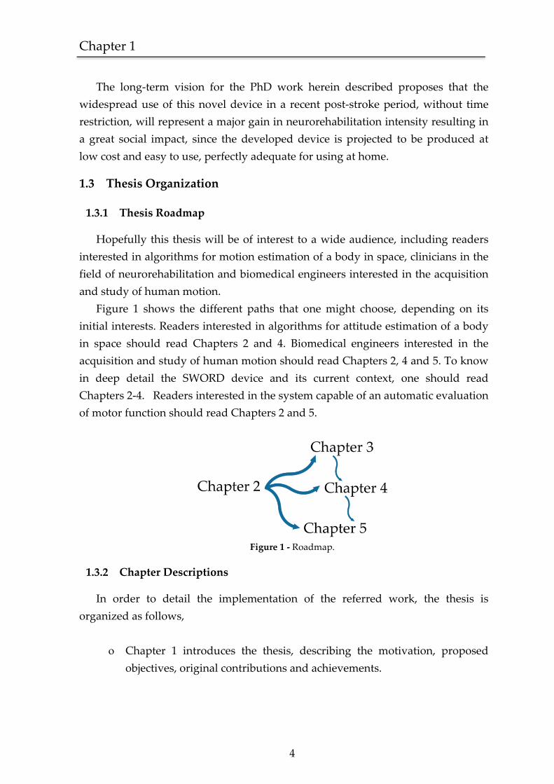
Figure 1 shows the different paths that one might choose, depending on its
initial interests. Readers interested in algorithms for attitude estimation of a body
in space should read Chapters 2 and 4. Biomedical engineers interested in the
acquisition and study of human motion should read Chapters 2, 4 and 5. To know
in deep detail the SWORD device and its current context, one should read
Chapters 2‐4. Readers interested in the system capable of an automatic evaluation
of motor function should read Chapters 2 and 5.
Figure 1 ‐ Roadmap.
1.3.2 Chapter Descriptions
In order to detail the implementation of the referred work, the thesis is
organized as follows,
Chapter 1 introduces the thesis, describing the motivation, proposed
objectives, original contributions and achievements.
5
Chapter 2 details the current state of the art in terms of the proposed
multidisciplinary work, introducing a general outline of the theoretical
and practical concepts that support our intervention, the validity of the
vibrotactile stimulus as a form of proprioceptive input to the CNS and
the different forms to quantify and qualify the kinematics inherent to
the assessment of human motion.
Chapter 3 presents the development of the stimulation device and the
respective results regarding the proof of concept study that was
performed with the objective of validating the tolerability and the
effectiveness of our approach based on the targeted delivery of
vibratory stimuli in a timed and weighted form.
Chapter 4 details the design principles of the SWORD device, respective
implementation and underlying rehabilitation methodology. Results
regarding the proficiency of the SWORD device in the increase of the
intensity of rehabilitation are also present.
Chapter 5 describes the developed system aimed at an automatic
evaluation of upper‐limb motor function after neurological injury.
Results regarding its effectiveness are also present.
Chapter 6 summarizes lessons learned, most relevant achievements,
major pitfalls, future directions and lines of research created by the
work herein presented.
1.4 Original contributions and achievements
The work that supports this PhD thesis is assumed, by the author, to represent
an important contribution to the research area of the technology‐based
interventions, designed to promote the recovery of motor function after brain
injury.
The SWORD device (described in Chapter 4) supports a new rehabilitation
methodology that aims to provide a more efficient recovery of the patient and, at
the same time, reduce health costs by providing a more efficient allocation of
clinical resources. The system depicted in Chapter 5 is, to the author’s knowledge,
Chapter 1
6
the first system capable of evaluating in an automatic form the score of the Wolf
Motor Function Test (WMFT), allowing for a continuous scoring of motor
performance in a precise and non‐bias form. The use of such an unbiased system is
of increased importance in clinical trials, where the proficiency of a rehabilitation
intervention is evaluated in terms of the measured evolution of the patient.
Furthermore, the movement quantification system developed to acquire the
dynamics of motor performance is suited to be applied in a plethora of different
research lines. One example of such application is in the ambulatory study of
neurological disorders that also manifest motor impairments, such as Parkinson’s
or Huntington’s disease. In more mainstream areas, applications range from the
swing analysis of a golf player to the videogames industry.
The work herein presented resulted in the following publications in peer
reviewed international scientific journals:
Bento V. F., Cruz V. T., Ribeiro D. D., Cunha J. P. S, “The vibratory stimulus as
a neurorehabilitation tool for stroke patients: proof of concept and tolerability
test”, NeuroRehabilitation. 2012 Jan 1; 30(4):287‐93. (5‐Year Impact Factor 1.99)
Bento V. F., Cruz V. T., Cunha J. P. S, “A novel movement quantification
system capable of automatic evaluation of upper limb motor function after
neurological injury: Proof‐of‐concept” (Submitted to Neurorehabilitation &
Neural Repair) (5‐Year Impact Factor 4.757)
And in the ensuing peer reviewed international conferences,
Bento V. F., Cruz V. T., Cunha J. P. S, ʺTowards and Intelligent Wearable
Vibratory Device to improve rehabilitation in Stroke Patients: A Tolerability
Test.ʺ Cerebrovascular Diseases 2010; Vol. 29 (supplement 2 ‐ Proceedings of
the 19th European Stroke Conference. Barcelona, Spain, May 25–28, 2010)
Bento V. F., Cruz V. T, Cunha J. P. S., Coutinho P., “Presenting the vibratory as
a neurorehabilitation tool ‐ a tolerability test” , Journal of Neurology 2011; Vol.
258 (supplement 1 ‐ Proceedings of the 21st Meeting of the European
Neurological Society, Lisbon, Portugal, May 28–31, 2011)
Bento V. F., Cruz V. T., Ribeiro D. D., Cunha J. P. S., “Towards a movement
quantification system capable of automatic evaluation of upper limb motor
7
function after neurological injury”. In Engineering in Medicine and Biology
Society (EMBC), 2011 Annual International Conference of the IEEE; Aug. 30 2011‐
Sept. 3 2011, Boston, USA
Bento V. F., Cruz V. T., Ribeiro D. D., Colunas M. M. Cunha J. P. S., “The
SWORD Tele‐Rehabilitation System”. In Proceedings of the 9th International
Conference on Wearable Micro and Nano Technologies for Personalized
Health (pHealth); June 26‐28, Porto, Portugal
Additionally, the SWORD device was also subject to intellectual property
protection through the patent,
PPP 43106/11 ‐ ʺSistema para estimulação proprioceptiva, monitorização e
caracterização de movimentoʺ
And receive the following awards,
“Highest Future Impact Demonstration in Wearable Technology”, 33rd Annual
International Conference of the IEEE Engineering in Medicine and Biology
Society (EMBC ’11), Aug. 30 2011‐Sept. 3 2011, Boston, USA
Open Finalist of the Student Paper Competition of the 33rd Annual
International Conference of the IEEE Engineering in Medicine and Biology
Society (EMBC ’11), Boston, Aug. 30 2011‐Sept. 3 2011, USA

Chapter 2 State of the art

Chapter 2
9
2.1 Motor Recovery after Stroke
2.1.2 Technology-based interventions
Rehabilitation is defined in medical terms as the process of making someone fit
to work or to live an ordinary life again [11]. This return to the initial competences
can be achieved by either restoring the innate aptitudes of the patient or by
substituting them for new ones. New rehabilitation advances have their basis on
the increasing knowledge about the neuronal plasticity mechanisms induced
either by damage or learning. These new approaches bisect a various number of
disciplines using physical and pharmacologic therapeutics, neuroprosthesis and
functional/mechanical methods that target the repair or partial substitution of the
damaged Central Nervous System (CNS).
In terms of robotic therapy, several devices have been proposed as reliable
rehabilitation tools in terms of stroke recovery. Nonetheless these attempts, still no
device is established in practice as an unequivocally efficient method [12, 13]. This
fact leads to a green field in terms of opportunity.
In spite of this lack of validity, robotic devices are becoming more commonly
used in stroke rehabilitation, aiming to improve arm function through the
repetitive practice of passive and active bilateral forearm and wrist movement
cycles. Such devices can be active for long periods, be programmed and have the
capacity to measure a wide range of behaviors. Level of demand on patients can
go from a purely passive experience, patient-initiated assistance or to feedback
only.
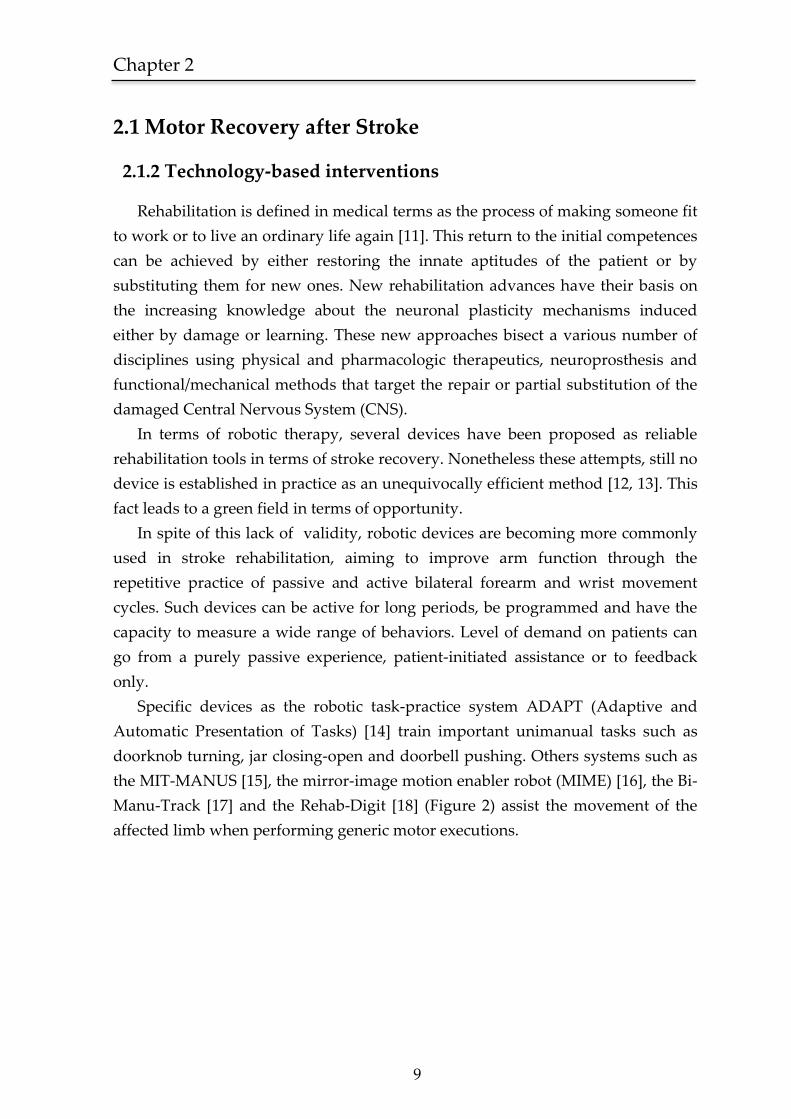
Specific devices as the robotic task-practice system ADAPT (Adaptive and
Automatic Presentation of Tasks) [14] train important unimanual tasks such as
doorknob turning, jar closing-open and doorbell pushing. Others systems such as
the MIT-MANUS [15], the mirror-image motion enabler robot (MIME) [16], the Bi-
Manu-Track [17] and the Rehab-Digit [18] (Figure 2) assist the movement of the
affected limb when performing generic motor executions.
10
Figure 2 - Hand function training device “Rehab-Digit” [18]
Electromyography (EMG) triggered robots [19] detect the attempt of a patient to
execute a motor action whereupon the robot assists him to perform the predefined
movement. This paradigm is also called myoelectric control.
However promising, the majority of these systems didn’t present conclusive
results regarding motor improvement in stroke patients. A recent systematic
review by Langhorne et. al. [13], evaluating randomized clinical trials focused on
the improvement of arm function, referred that interventions that included EMG
feedback and robotics could have a potential effect on the recovery of arm
function. Although, due to the small number of participants in each study, these
current findings could easily be overturned by more extensive and valid trials. An
important limitation that restricts the efficiency of robotic devices based
therapeutics is its lack of availability in the usual health care centers. This type of
systems incorporate very high costs of production and complexity, demanding
permanent professional supervision, which competes with the existing scarcity of
human resources becoming only available for very specific patients and with a
limited exposure to treatment. This fact assumes a major importance for stroke
outcome in the population, since the extension of recovery is highly correlated
with the intensity of the rehabilitation program [12, 20].
2.1.3 Recommendations for treatment
The most promising neurorehabilitation therapies have their focus on the
repair and restoration of function in the subacute phase that takes place in the first
three to six months after Stroke onset [12]. These include device-based approaches,
Chapter 2
11
electromagnetic stimulation, and task-oriented repetitive training interventions
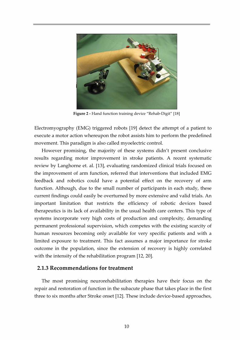
[12, 13, 21, 22] . Overall, the considered most promising interventions for upper-
limb recovery of function are the ones based on the constraint-induced movement
of the arm (Figure 3).
Figure 3 - Review of the interventions designed to improve upper-limb motor function after
stroke in terms of the intervention category, number of participants recruited and the 95%
confidence interval for the effect of the intervention on the outcome measure. Results show that
interventions based on the constraint-induced movement of the arm are the ones that show a
higher proficiency. The most common outcome measures used in the evaluation of motor
improvement of the upper-limb where the action research arm test, motor assessment scale and the
Fugl-Meyer scale (adapted from [21]).
Still, such intervention is only suitable to be applied to a very specific
population (with limited arm impairment and able to tolerate prolonged arm
constraint). A common element present in the most promising interventions
(either technological or non-technological) is the high-intensity repetition of
specific tasks. Langhorne et al [13] stated, as a concluding remark, that “the main
general recommendations seem to be that the alleviation of motor impairment and
restoration of motor function should (as much as possible) focus on high-intensity,
repetitive task-specific practice with feedback on performance”. Additionally, Cramer et
al [12], suggested that “ultimately, a combination therapy targeting several processes
may prove superior to any monotherapy.”
Furthermore, an effective methodology for stroke rehabilitation should follow
the pattern of recovery of the patient after stroke onset (Figure 4).
12
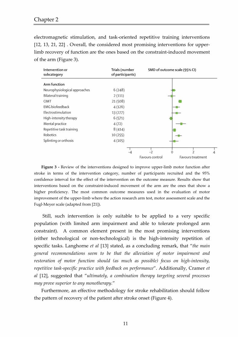
Figure 4 - Pattern of functional motor recovery for a patient after Stroke onset subjected to an
effective therapy (adapted from [13])
This implies that the proposed therapeutic should stimulate a maximum intensity
of training in the first three to six months period, where major gains in cognitive
and motor function occurs.
2.2 The vibratory stimulus
2.2.1 Historical perspective
Charcot’s Chair
Jean-Martin Charcot (1825-1893) was one of the greatest neurologists of the
nineteenth century. His work, as he stated, was primarily based on observation:
“Let someone say of a doctor that he really knows his physiology or anatomy, that he is
dynamic - these are not real compliments; but if you say he is an observer, a man who
know how to see, this is perhaps the greatest compliment one can make” [23]. This
approach led to several pioneering findings, such as the diagnostic difference
between Multiple Sclerosis (MS) and Parkinson Disease (PD) based on the type of
tremor that each patient showed.
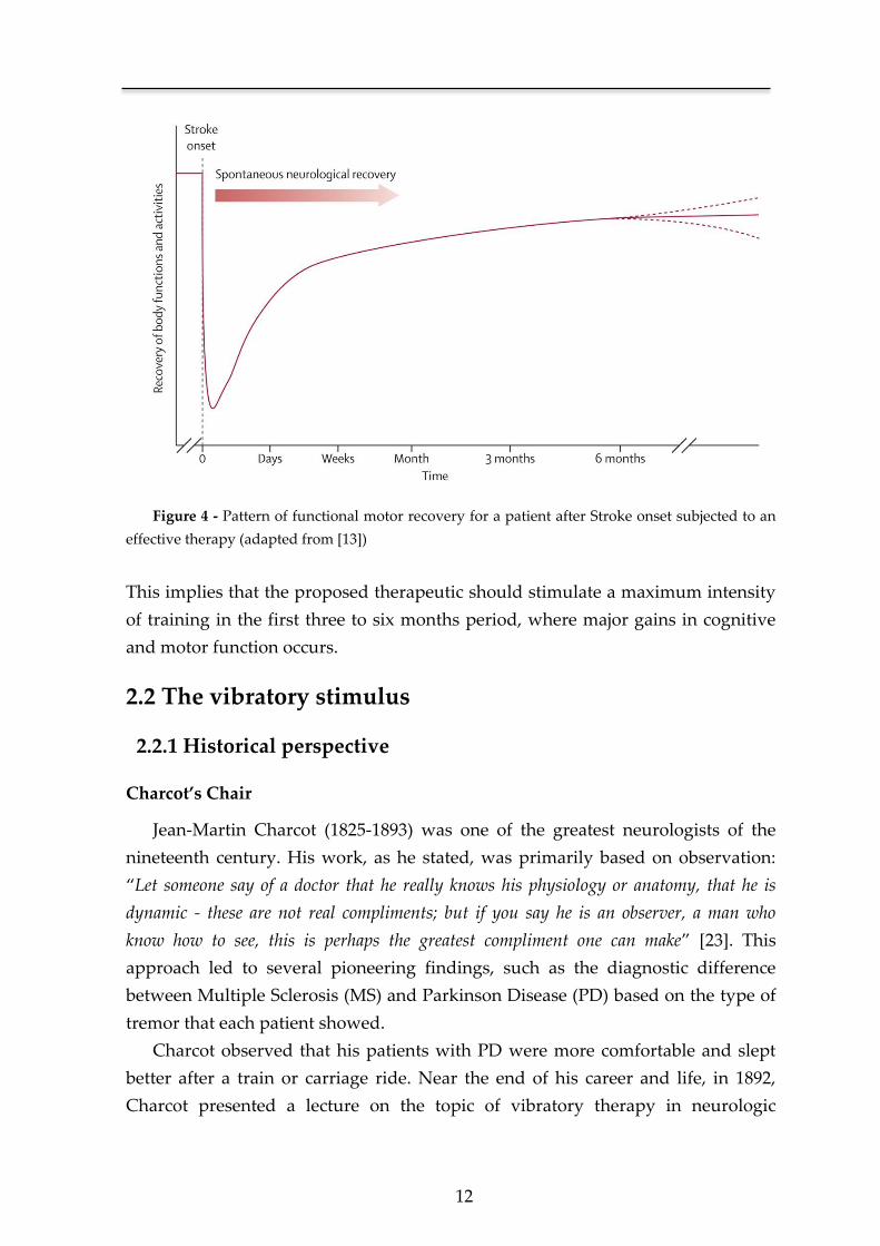
Charcot observed that his patients with PD were more comfortable and slept
better after a train or carriage ride. Near the end of his career and life, in 1892,
Charcot presented a lecture on the topic of vibratory therapy in neurologic
Chapter 2
13
disorders entitled “Vibration therapeutics: Application of rapid and continuous
vibrations to the treatment of certain nervous system disorders” [24]. In this lecture he
outlined the historical background of vibration therapy and theorized about a
possible therapeutic for PD based on vibration. Charcot noted that vibrations
applied to the skin, joints, or full body could enhance the therapeutic of several
neurological disorders. In order to replicate the exact reality of a carriage ride he
projected a vibratory chair (Figure 5) with the objective to produce a trembling
very close to what a patient would experience when riding on the seat of an open
wagon. The experimental paradigm was based on a series of patients with PD,
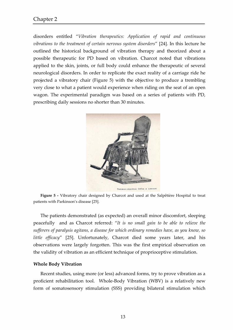
prescribing daily sessions no shorter than 30 minutes.
Figure 5 - Vibratory chair designed by Charcot and used at the Salpêtière Hospital to treat
patients with Parkinson’s disease [25].
The patients demonstrated (as expected) an overall minor discomfort, sleeping
peacefully and as Charcot referred: “It is no small gain to be able to relieve the
sufferers of paralysis agitans, a disease for which ordinary remedies have, as you know, so
little efficacy” [25]. Unfortunately, Charcot died some years later, and his
observations were largely forgotten. This was the first empirical observation on
the validity of vibration as an efficient technique of proprioceptive stimulation.
Whole Body Vibration
Recent studies, using more (or less) advanced forms, try to prove vibration as a
proficient rehabilitation tool. Whole-Body Vibration (WBV) is a relatively new
form of somatosensory stimulation (SSS) providing bilateral stimulation which
14
theoretically induces plastical changes in both hemispheres. Another important
feature of WBV is the main excitatory effect that occurs at the foot-sole afferents
which are identified to play an important role in postural control [26]. This
technique has shown preliminary evidences [27] of short-term benefits on postural
stability in patients with chronic stroke. However, as a long-lasting rehabilitation
tool in stroke, WBV (Figure 6) hasn’t been proved effective when applied during
daily sessions in a 6-Week trial [28], being considered innocuous regarding
improvements in muscle strength and somatosensory afferences. This is probably
due to the fact that the most promising findings regarding WBV are related with
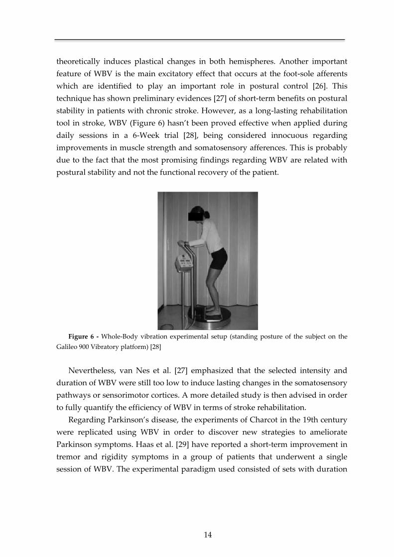
postural stability and not the functional recovery of the patient.
Figure 6 - Whole-Body vibration experimental setup (standing posture of the subject on the
Galileo 900 Vibratory platform) [28]
Nevertheless, van Nes et al. [27] emphasized that the selected intensity and
duration of WBV were still too low to induce lasting changes in the somatosensory
pathways or sensorimotor cortices. A more detailed study is then advised in order
to fully quantify the efficiency of WBV in terms of stroke rehabilitation.
Regarding Parkinson’s disease, the experiments of Charcot in the 19th century
were replicated using WBV in order to discover new strategies to ameliorate
Parkinson symptoms. Haas et al. [29] have reported a short-term improvement in
tremor and rigidity symptoms in a group of patients that underwent a single
session of WBV. The experimental paradigm used consisted of sets with duration
Chapter 2
15
of 60 seconds each applying stochastic1 vibration with a fundamental frequency of
6 Hz. However, these improvements weren’t corroborated by other studies [30, 31]
that reported a significant placebo effect. The different results between studies
could be due to the fact that in one study they used stochastic vibration against the
non-stochastic method used in the studies where the improvement on PD
symptoms was reported as placebo effect. This fact remains subject of debate in
part due to the fact that the type of vibration used is not the same, leading to
diverging results. A comparison study is then needed using the same vibration
platform and the same definition of vibratory stimulus in order to achieve a
precise conclusion about the topic in question.
Functional Vibratory Stimulation
This is a relatively new research topic in the neurorehabilitation context where
the study of the effect of the vibratory stimulus in the CNS is almost uniquely
explored in the WBV approach. The lack of interest on the Functional Vibratory
Stimulation (FVS) approach could be due in part to its complexity concerning
vibratory actuators, type of vibration and points of excitation. Few studies are
focused on the efficiency of vibratory stimulus when applied directly to the
patient’s arm. FVS contrasts with WBV not only on the vibration target, a local
area versus the whole body, but also on the form of vibration.
In the WBV chapter it was briefly denoted two types of vibration, a stochastic
and a non-stochastic one. The stochastic part indicates the lack of determinism in
the amplitude form, being constant, for either one of the cases, its frequency form.
In FVS, for example, the vibratory stimulus can consist on a series of high
amplitude bursts followed by a low amplitude vibration. The periodicity of these
bursts can be deterministic or stochastic changing the frequency form of the
stimulus. This is just one example of how a vibratory stimulus could be shaped.
Another hypothesis is the use of a vibration pathway, connecting sensory dots
using the wave property of the vibration. A possible application of this is the
sequential stimulation of the three different joints of the arm (wrist, elbow and
shoulder). In fact, the experimentation of all these possibilities is a very important
study in order to fully understand how a vibratory stimulus is propagated in the
1 A stochastic process or signal relates to a physical model that contains a random element that
outcome a non-deterministic pattern. All natural events are stochastic phenomenon, characterized
by means of a probabilistic function due to its randomness. The word stochastic derives originally
from the Greek word stochos which direct translation is aim or guess.
16
CNS architecture. The point in question in FVS is if this propagation will lead to a
proficient excitatory effect on the CNS and consequentially an enhanced
rehabilitation.
Kawahira K., et al., [32] and Shirahashi I. et al., [33] implemented an
experimental paradigm in order to prove the aptitude of FVS in terms of stroke
recovery. However inconclusive, due to a low statistical significance, both
Kawahira and Shirahashi propose the FVS as a promising rehabilitation tool. An
important characteristic present in both works is the simplicity of the vibratory
excitation method used, which, in such a complex topic, could easily lead to
misleading results. Due to these facts, our work using FVS is not supported on this
erstwhile scientific approach. The findings pursued were based on the
multidisciplinary research data that is interconnected, such as, Whole-Body
Vibration [27, 28], pre-operative brain scans [34] and the diverse work relating
vibration and the excitability of the CNS [35-37].
More recently, Conrad et al [38], evaluated the effects of wrist tendon vibration
on paretic upper-arm stability during point-to-point planar movements, in 10
hemiparetic stroke patients. The results suggest that with the vibratory stimulus,
there is an increase stability of the proximal arm in the execution of the motor
tasks.
2.2.2 Background physiopathological principles
Despite an early phase in understanding the process of CNS rehabilitation in
human adults, current findings support the development of new interventions,
aimed at recovering lost motor function from unaffected neuronal circuits,
namely, sensory afferences that can preserve and recover sensitive and motor
cortex organization [39]. The ensuing neurological formulations support the
development of a stroke therapy based on the intensive delivery of external
stimuli.
Human Beings have both sensory and motor skills. The former develop a
structured map of the body and environment in which the latter act. In any
interaction with the environment, there is always an optimization algorithm of the
tasks carried out. This algorithm is supported by the neural plasticity and network
architecture of the CNS that allows the integration of new stimulus and the
necessary adaptation to successfully perform new tasks.
Chapter 2
17
Maturation of the sensory and motor functions occurs jointly, developing an
integrated architecture between the two. Due to this fact, there are numerous
interconnected centers in the spine, brain stem, thalamus and cortex, resulting in
several pathways of interconnection. This type of organization makes the system
to function, not as a bidirectional flux of information, but rather in a network
mode. This accounts for several advantages, such as the adaptation to new
situations and stimuli or the recovery from damage [40].
When injury occurs in the CNS, consequences will result from the location and
dimension of damage as well as from the age, because it is different if it occurs
over an established system or a developing one. The intrinsic mechanisms for
reducing neurological damage in an adult subject rely on one hand on the network
structure depicted before, that prevents injuries with total consequences
(anesthesia or plegia), and on the other hand on neuronal plasticity and the
possibility for recapitulating part of the maturing process in adulthood, aiding the
reorganization of the structures that remain unaffected [40, 41].
The network functioning exists both for motor and sensory tasks [42].
However, at the CNS level, it is much more developed for sensory functions [43].
This fact results in that for the majority of lesion models to the CNS (ischemic or
hemorrhagic stroke, trauma) there is usually a greater damage in motor than in
sensory functions. Besides, motor deficits represent a greater impair for patients.
When lesions occur in the upper levels of CNS (cortex, thalamus), there is a
diminishment of the inhibitory output of this center on the structures located
bellow. This fact amplifies certain sensory stimuli that previously were not able to
evoke cortical stimulation [44]. Therefore, higher placed structures, with a more
complex organization, can be reorganized from preserved sensory stimuli.
Plasticity of the injured motor cortex depends on the use of the affected limb,
this being true for patients with ischemic damage well as for normal people [39,
45]. Possibly, neighboring cortex is recruited and assumes for lost motor functions
when stimulated. This way, in lesion models, recovery of motor function is
necessarily antedated by a reconstitution of the cortical map of the affected side of
the body. This phenomenon of cortical remapping is conditioned through
stimulation via the preserved sensory afferences [12, 46].
18
The network organization of the CNS represents a non-linear system where
sensory and specifically proprioceptive2 information flows through several
hierarchic levels, allowing a maximum efficiency on motor performance. Using
this property of non-linearity is possible to potentiate preserved sensory afferences
by means of vibratory stimuli. It can be directly applied over major joints, or
through the injection of noise in the system using low intensity vibration [9]. This
theoretical principle has been demonstrated in several biological systems [47],
having already some technical applications [48].
2.2.3 Stimulus-based neurorehabilitation approaches
Parallel to the use of a vibratory stimulus to promote the recovery of the
injured CNS, coexists the neurorehabilitation intervention based on the use of
electromagnetic stimuli. Our brain and the peripheral nervous system consume
20% of the available energy of the body. A substantial part of this energy is used to
maintain the potential of the membranes which is the basis of intra-neuronal
communication. Since many neurological disorders have their underlying
foundation on a faulty communication between neuronal groups, it’s logical to
assume that the modulation of an electrical current between neurons can stimulate
or reorganize the communication path and thus restore the lost functions [12].
Transcranial magnetic stimulation (TMS) has been widely used for the
treatment of major depression, against which the performance of antidepressant
intervention is compared [49]. In stroke rehabilitation, it aims to modulate a
number of functions and behaviors that a damaged CNS cannot provide. Different
goals have been pursued in this area. Some studies [50, 51] aimed to increase
activity in brain areas showing reduced function after stroke, whereas others
focused on reducing activity in brain areas theorized to have a deleterious
suppressive effect. One of the most notorious examples of an electromagnetic
stimulation approach is repetitive TMS (rTMS) (Figure 7) which, depending on the
number of stimuli per second, can have an inhibitory or excitatory effect on
cortical activity.
2 Proprioception is the process by which a sensory receptor detects the motion or position of a limb by
responding to stimuli arising within the organism. The word “proprioception” was initially coined by Charles
Sherrington, the Nobel Prize in Physiology and Medicine in 1932, in the study of the neuron and the reflex
action.
Chapter 2
19
Figure 7 - A figure-of-eight shaped TMS coil placed on the subject’s head using a mechanical
coil holder. A brief electrical current generates a magnetic field around the coil windings which, in
turn, induces electrical currents in the brain that flows in parallel but opposite to those in the TMS
coil [52].
Nonetheless, strategies found in literature for increasing activity in
ipsilesional cortical regions that are underactive or decreasing activity in
contralesional regions that are overactive did not correlate (so far) with better
achievements in stroke outcome. Recent studies [53, 54] using rTMS as a stroke
rehabilitation tool showed that a single session targeting the unaffected
hemisphere can improve motor function in stroke patients for a short period of
time.
Another example of an electromagnetic stimulation device that has been
increasingly used in cases of spinal cord injury [55], cerebral palsy [56] and stroke
[57] is Functional Electrical Stimulation (FES). Essentially the purpose of a FES
system is to repair the affected CNS through the injection of an electrical current in
order to activate nerves innervating extremities. A conceptual design of a FES
system [58] is depicted in Figure 8.
20
Figure 8 - Implanted FES hand grasp system [58].
Due to its moderate results, the effectiveness of FES in stroke patients remains
a subject of debate [51]. A phase III study considering 164 chronic stroke patients
demonstrated that, in terms of motor status, epidural motor cortex stimulation
plus rehabilitation therapy didn’t considerably differed from rehabilitation
therapy alone [59].
2.2.4 Vibration as a stimulus for cortical activation
All somatic sensory receptors work in the same way. When a stimulus is
received, there is a deformation on the skin (a change in the nerve endings) which
will affect the ionic permeability of the receptor membrane. This change on the
permeability generates a depolarizing current in the nerve ending producing a
receptor potential that triggers action potentials. These, through a propagation
phenomenon combined with an intrinsic network structure, will stimulate all
structures in the upper hierarchy of the CNS. This physiological process is called
sensory transduction and it is the first step in all sensory processing [60].
Chapter 2
21
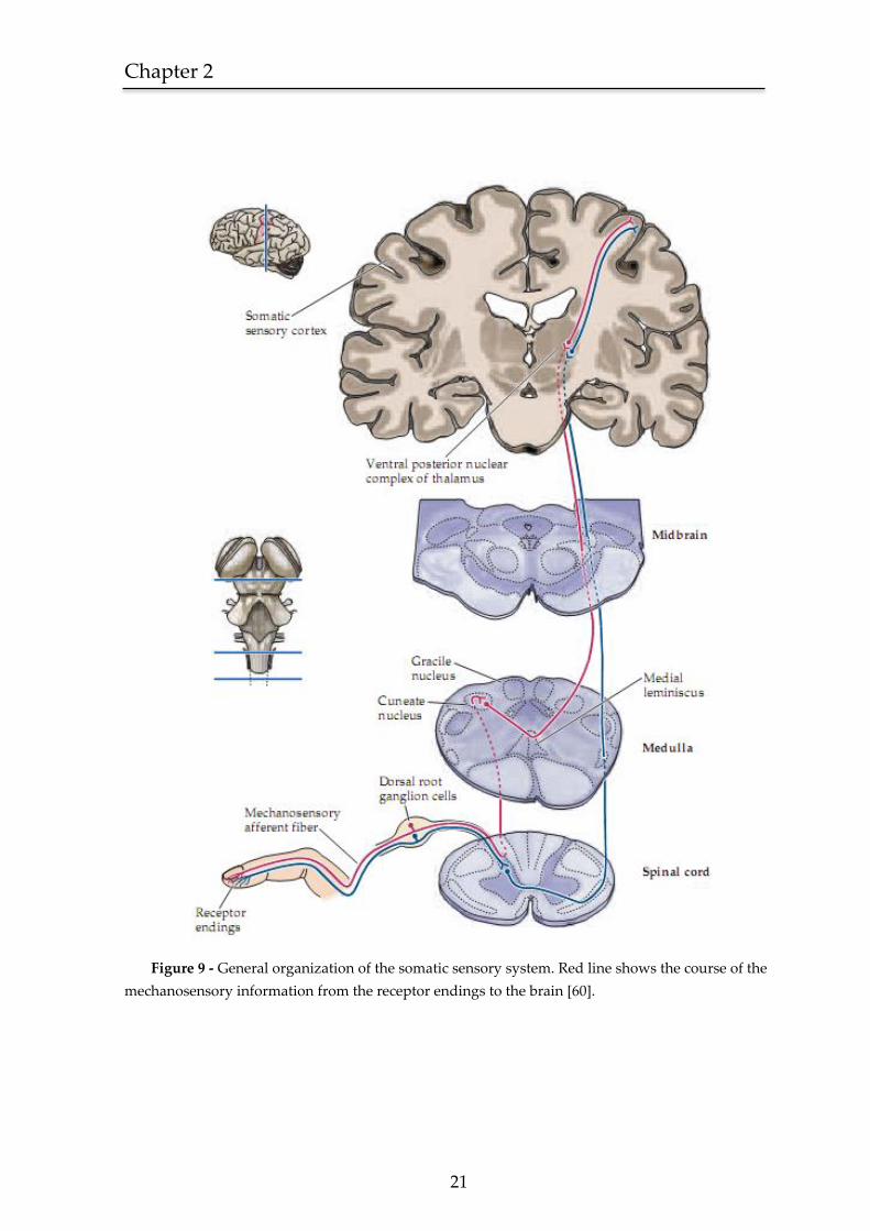
Figure 9 - General organization of the somatic sensory system. Red line shows the course of the
mechanosensory information from the receptor endings to the brain [60].
22
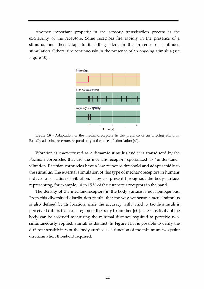
Another important property in the sensory transduction process is the
excitability of the receptors. Some receptors fire rapidly in the presence of a
stimulus and then adapt to it, falling silent in the presence of continued
stimulation. Others, fire continuously in the presence of an ongoing stimulus (see
Figure 10).
Figure 10 - Adaptation of the mechanoreceptors in the presence of an ongoing stimulus.
Rapidly adapting receptors respond only at the onset of stimulation [60].
Vibration is characterized as a dynamic stimulus and it is transduced by the
Pacinian corpuscles that are the mechanoreceptors specialized to “understand”
vibration. Pacinian corpuscles have a low response threshold and adapt rapidly to
the stimulus. The external stimulation of this type of mechanoreceptors in humans
induces a sensation of vibration. They are present throughout the body surface,
representing, for example, 10 to 15 % of the cutaneous receptors in the hand.
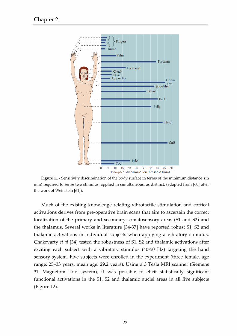
The density of the mechanoreceptors in the body surface is not homogenous.
From this diversified distribution results that the way we sense a tactile stimulus
is also defined by its location, since the accuracy with which a tactile stimuli is
perceived differs from one region of the body to another [60]. The sensitivity of the
body can be assessed measuring the minimal distance required to perceive two,
simultaneously applied, stimuli as distinct. In Figure 11 it is possible to verify the
different sensitivities of the body surface as a function of the minimum two-point
discrimination threshold required.
Chapter 2
23
Figure 11 - Sensitivity discrimination of the body surface in terms of the minimum distance (in
mm) required to sense two stimulus, applied in simultaneous, as distinct. (adapted from [60] after
the work of Weinstein [61]).
Much of the existing knowledge relating vibrotactile stimulation and cortical
activations derives from pre-operative brain scans that aim to ascertain the correct
localization of the primary and secondary somatosensory areas (S1 and S2) and
the thalamus. Several works in literature [34-37] have reported robust S1, S2 and
thalamic activations in individual subjects when applying a vibratory stimulus.
Chakrvarty et al [34] tested the robustness of S1, S2 and thalamic activations after
exciting each subject with a vibratory stimulus (40-50 Hz) targeting the hand
sensory system. Five subjects were enrolled in the experiment (three female, age
range: 25–33 years, mean age: 29.2 years). Using a 3 Tesla MRI scanner (Siemens
3T Magnetom Trio system), it was possible to elicit statistically significant
functional activations in the S1, S2 and thalamic nuclei areas in all five subjects
(Figure 12).
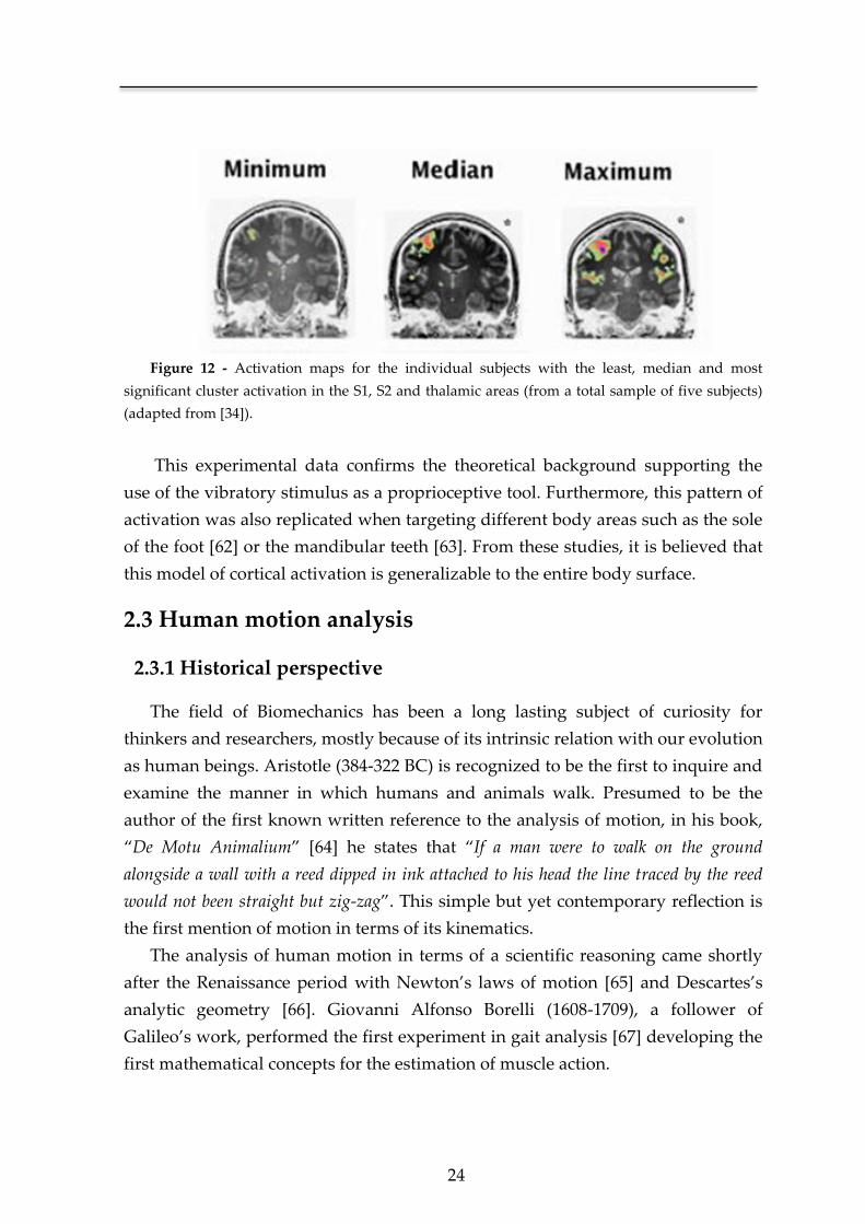
24
Figure 12 - Activation maps for the individual subjects with the least, median and most
significant cluster activation in the S1, S2 and thalamic areas (from a total sample of five subjects)
(adapted from [34]).
This experimental data confirms the theoretical background supporting the
use of the vibratory stimulus as a proprioceptive tool. Furthermore, this pattern of
activation was also replicated when targeting different body areas such as the sole
of the foot [62] or the mandibular teeth [63]. From these studies, it is believed that
this model of cortical activation is generalizable to the entire body surface.
2.3 Human motion analysis
2.3.1 Historical perspective
The field of Biomechanics has been a long lasting subject of curiosity for
thinkers and researchers, mostly because of its intrinsic relation with our evolution
as human beings. Aristotle (384-322 BC) is recognized to be the first to inquire and
examine the manner in which humans and animals walk. Presumed to be the
author of the first known written reference to the analysis of motion, in his book,
“De Motu Animalium” [64] he states that “If a man were to walk on the ground
alongside a wall with a reed dipped in ink attached to his head the line traced by the reed
would not been straight but zig-zag”. This simple but yet contemporary reflection is
the first mention of motion in terms of its kinematics.
The analysis of human motion in terms of a scientific reasoning came shortly
after the Renaissance period with Newton’s laws of motion [65] and Descartes’s
analytic geometry [66]. Giovanni Alfonso Borelli (1608-1709), a follower of
Galileo’s work, performed the first experiment in gait analysis [67] developing the
first mathematical concepts for the estimation of muscle action.
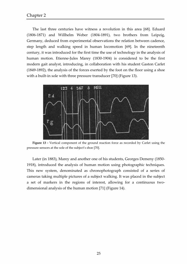
Chapter 2
25
The last three centuries have witness a revolution in this area [68]. Eduard
(1806-1871) and Willhelm Weber (1804-1891), two brothers from Leipzig,
Germany, deduced from experimental observations the relation between cadence,
step length and walking speed in human locomotion [69]. In the nineteenth
century, it was introduced for the first time the use of technology in the analysis of
human motion. Etienne-Jules Marey (1830-1904) is considered to be the first
modern gait analyst, introducing, in collaboration with his student Gaston Carlet
(1849-1892), the analysis of the forces exerted by the foot on the floor using a shoe
with a built-in sole with three pressure transducer [70] (Figure 13).
Figure 13 - Vertical component of the ground reaction force as recorded by Carlet using the
pressure sensors at the sole of the subject’s shoe [70].
Later (in 1883), Marey and another one of his students, Georges Demeny (1850-
1918), introduced the analysis of human motion using photographic techniques.
This new system, denominated as chronophotograph consisted of a series of
cameras taking multiple pictures of a subject walking. It was placed in the subject
a set of markers in the regions of interest, allowing for a continuous two-
dimensional analysis of the human motion [71] (Figure 14).
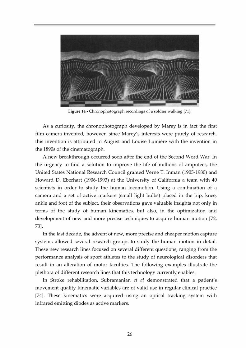
26
Figure 14 - Chronophotograph recordings of a soldier walking [71].
As a curiosity, the chronophotograph developed by Marey is in fact the first
film camera invented, however, since Marey’s interests were purely of research,
this invention is attributed to August and Louise Lumière with the invention in
the 1890s of the cinematograph.
A new breakthrough occurred soon after the end of the Second Word War. In
the urgency to find a solution to improve the life of millions of amputees, the
United States National Research Council granted Verne T. Inman (1905-1980) and
Howard D. Eberhart (1906-1993) at the University of California a team with 40
scientists in order to study the human locomotion. Using a combination of a
camera and a set of active markers (small light bulbs) placed in the hip, knee,
ankle and foot of the subject, their observations gave valuable insights not only in
terms of the study of human kinematics, but also, in the optimization and
development of new and more precise techniques to acquire human motion [72,
73].
In the last decade, the advent of new, more precise and cheaper motion capture
systems allowed several research groups to study the human motion in detail.
These new research lines focused on several different questions, ranging from the
performance analysis of sport athletes to the study of neurological disorders that
result in an alteration of motor faculties. The following examples illustrate the
plethora of different research lines that this technology currently enables.
In Stroke rehabilitation, Subramanian et al demonstrated that a patient’s
movement quality kinematic variables are of valid use in regular clinical practice
[74]. These kinematics were acquired using an optical tracking system with
infrared emitting diodes as active markers.
Chapter 2
27
In a different but equally important medical area, following the pioneer work
achieved by Li et al [75] and Cunha et al [76], O’Dwyer et al evaluated the
lateralizing significance of ictal head movements of patients with temporal lobe
epilepsy (TLE), using a single camera for tracking head movements [77]. Also in
this area of research, Cunha et al developed a 3D system that, as expected,
obtained a superior robustness and precision when compared against the
traditional 2D movement quantification method [78].
In the study of Parkinson’s disease, Hong et al analyzed the movement
kinematics of patients in order to assess if there was an objective difference in
turning when compared against normal subjects [79]. This study used an eight
camera three-dimensional motion capture system to record the kinematic data.
2.3.2 Motion capture technology
As stated earlier, this area suffered an impressive technological advance in
the last ten years. A big part of this evolution is due to the needs of the high-
budget industry of filmmaking and videogames. Different approaches have been
pursued in order to acquire the kinematics of human motion, with a clear frontier
between optical and non-optical systems.
In motion capture systems, the definition of a gold standard is very specific
to the application proposed, where instead of a silver bullet we have a respectable
and diversified arsenal [80]. For example, in the industry of filmmaking and video
games the gold standard for motion capture systems is in a solution that combines
an optical system with (passive or active) markers on the subject. One of the most
advanced systems of this kind, the Vicon MX® [81], has a three dimensional spatial
accuracy of 0.1 mm. These systems are also commonly used in sports in the
analysis and quantification of the performed motor execution (Figure 15).
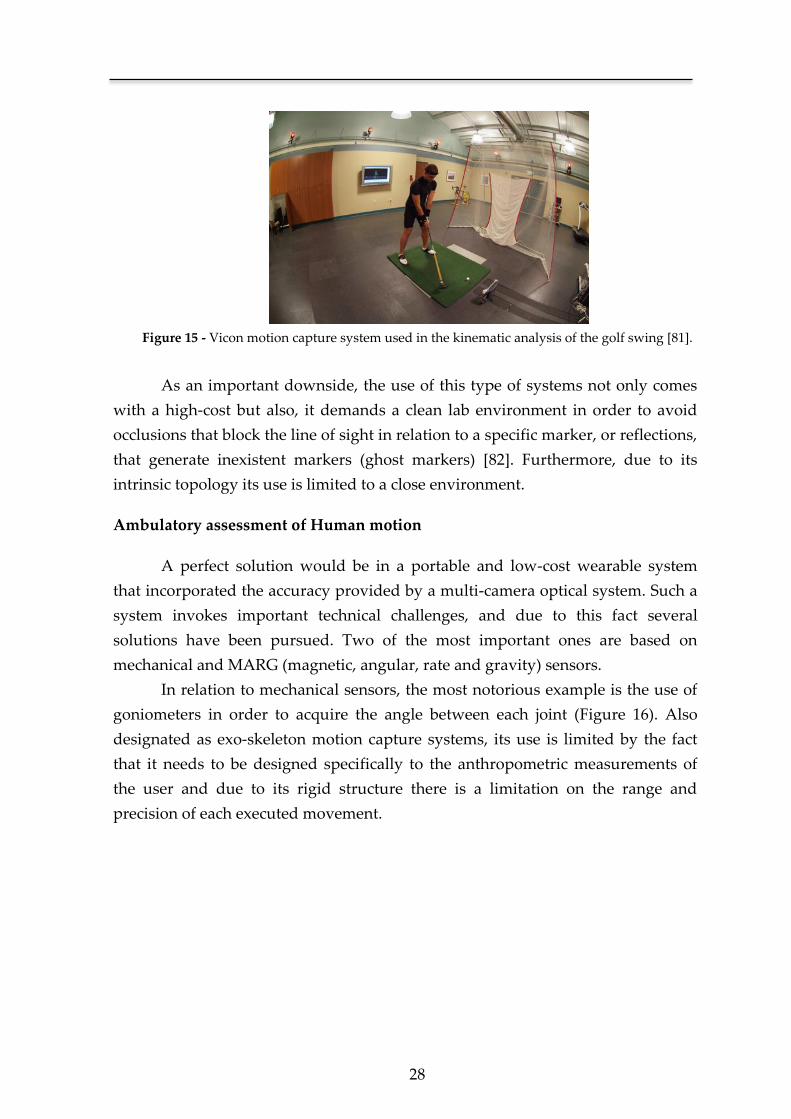
28
Figure 15 - Vicon motion capture system used in the kinematic analysis of the golf swing [81].
As an important downside, the use of this type of systems not only comes
with a high-cost but also, it demands a clean lab environment in order to avoid
occlusions that block the line of sight in relation to a specific marker, or reflections,
that generate inexistent markers (ghost markers) [82]. Furthermore, due to its
intrinsic topology its use is limited to a close environment.
Ambulatory assessment of Human motion
A perfect solution would be in a portable and low-cost wearable system
that incorporated the accuracy provided by a multi-camera optical system. Such a
system invokes important technical challenges, and due to this fact several
solutions have been pursued. Two of the most important ones are based on
mechanical and MARG (magnetic, angular, rate and gravity) sensors.
In relation to mechanical sensors, the most notorious example is the use of
goniometers in order to acquire the angle between each joint (Figure 16). Also
designated as exo-skeleton motion capture systems, its use is limited by the fact
that it needs to be designed specifically to the anthropometric measurements of
the user and due to its rigid structure there is a limitation on the range and
precision of each executed movement.
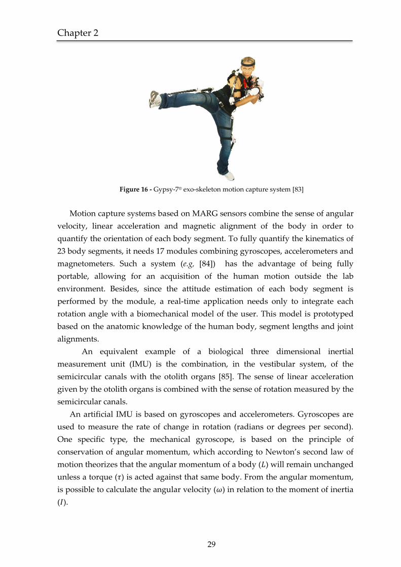
Chapter 2
29
Figure 16 - Gypsy-7® exo-skeleton motion capture system [83]
Motion capture systems based on MARG sensors combine the sense of angular
velocity, linear acceleration and magnetic alignment of the body in order to
quantify the orientation of each body segment. To fully quantify the kinematics of
23 body segments, it needs 17 modules combining gyroscopes, accelerometers and
magnetometers. Such a system (e.g, [84]) has the advantage of being fully
portable, allowing for an acquisition of the human motion outside the lab
environment. Besides, since the attitude estimation of each body segment is
performed by the module, a real-time application needs only to integrate each
rotation angle with a biomechanical model of the user. This model is prototyped
based on the anatomic knowledge of the human body, segment lengths and joint
alignments.
An equivalent example of a biological three dimensional inertial
measurement unit (IMU) is the combination, in the vestibular system, of the
semicircular canals with the otolith organs [85]. The sense of linear acceleration
given by the otolith organs is combined with the sense of rotation measured by the
semicircular canals.
An artificial IMU is based on gyroscopes and accelerometers. Gyroscopes are
used to measure the rate of change in rotation (radians or degrees per second).
One specific type, the mechanical gyroscope, is based on the principle of
conservation of angular momentum, which according to Newton’s second law of
motion theorizes that the angular momentum of a body ( ) will remain unchanged
unless a torque ( ) is acted against that same body. From the angular momentum,
is possible to calculate the angular velocity ( ) in relation to the moment of inertia
( ).
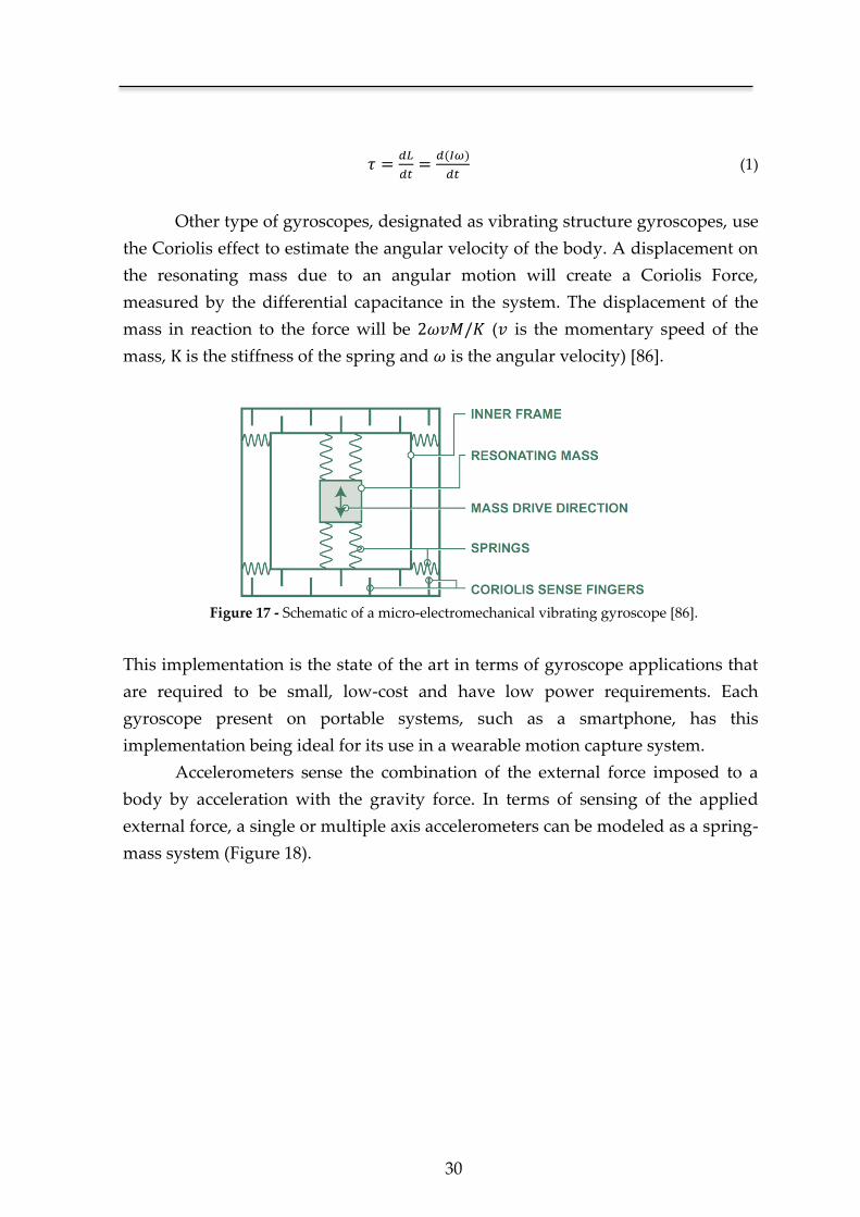
30
(1)
Other type of gyroscopes, designated as vibrating structure gyroscopes, use
the Coriolis effect to estimate the angular velocity of the body. A displacement on
the resonating mass due to an angular motion will create a Coriolis Force,
measured by the differential capacitance in the system. The displacement of the
mass in reaction to the force will be ( is the momentary speed of the
mass, K is the stiffness of the spring and is the angular velocity) [86].
Figure 17 - Schematic of a micro-electromechanical vibrating gyroscope [86].
This implementation is the state of the art in terms of gyroscope applications that
are required to be small, low-cost and have low power requirements. Each
gyroscope present on portable systems, such as a smartphone, has this
implementation being ideal for its use in a wearable motion capture system.
Accelerometers sense the combination of the external force imposed to a
body by acceleration with the gravity force. In terms of sensing of the applied
external force, a single or multiple axis accelerometers can be modeled as a spring-
mass system (Figure 18).

Chapter 2
31
Figure 18 - Simplified model of a spring-mass system, displaying the effect of the imposed
acceleration (a) on the displacement (xdis) of the mass (m). This model is analogous to the inner
structure of a single-axis micro-electromechanical accelerometer system.
The acceleration (a) acted upon the body is given by the relation between the
displacement (xdis) of the mass (m) in relation to the spring constant (k). From
Hooke’s law, we have that the force imposed on the mass is given by .
Relating this statement with Newton’s second law of motion ( we have,
(2)
The real measure sensed by an accelerometer is thus given by,
(3)
Where is the linear acceleration of the body and g is the gravitational
acceleration. The state of the art technology in terms of light weight and low cost
accelerometers, the MEMS accelerometer, use this operative method [87].
Sensor Fusion Algorithms
The estimation of the orientation of a body in relation to its inertial frame
(also called earth frame) consists in the compensation of the error present in a
primary source of information, for example the gyroscope’s angular velocity ( ),
with other error independent measures of orientation.
Simply numerically integrating the angular velocity given by the gyroscope
in the instant k ( is the sampling period),
32
(4)
Will result in an increasing integration error in the calculated rotation of the body
frame in relation to the earth frame (
). Each gyroscope measure can be modeled
as,
(5)
where is the true value for the rate of rotation of the body-frame in relation to
the earth-frame, is a slowly time-varying bias and is as zero mean noise
process. The bias factor is due to effects of temperature and motion on the
gyroscope model depicted in Figure 17. Therefore, at each instant k, the
integration of the gyroscope measure will also imply the integration of the bias
and noise, resulting in a cumulative divergence of the estimate over time [88].
The specification of the sensor fusion algorithm, methodology and sources
of information is subjected to the proposed application. Several different measures
can be used to measure orientation, like the ones previously described,
(gyroscopes, accelerometers, magnetometers) and others such as GPS and
altimeters. The state of art described herein, in terms of sensor fusion algorithms,
will focus on strapdown systems. In this type of systems, the sensor unit is
strapped directly to the body, and the obtained orientation is referenced to the
earth-frame [89]. A human motion capture system is a specific implementation of
a strapdown methodology.
In terms of generic motion capture systems, Kalman filters [90] are widely
used, both in research ([91], [92], [93], [94], [95]) and in commercial solutions
(Xsens [84], Intersense [96], Crossbow [97], VectorNav [98], PNI [99] and
MicroStrain [100]). However, due to the multi segment nature of human motion
capture, it demands a large state vector and an extended Kalman filter
implementation to linearize the estimation process [91]. This fact leads to a heavy
computational load that competes with the requirement of portability and low
consumption of a wearable configuration. Several other approaches have been
pursued. One simplistic approach [101] is based on the complementary filtering of
the acquired (gyroscope and accelerometer) data, selecting as the source of
information the accelerometer measurements in case of low angular velocities and
gyroscope measurements in case of high angular velocities. The accuracy of this
solution is subject to restrictive conditions not being suitable for an efficient
Chapter 2
33
human motion capture. Other simplistic, yet, successful approach based on the use
of a complementary filter is presented by Mahony et al [102, 103]. This approach
was developed having in mind the estimation of the dynamics (rotation and
translation) of a fixed-wing UAV (unmanned aerial vehicle). This solution was
only applied to the estimation of an IMU unit, since that is the case of a fixed-wing
UAV (such a vehicle only performs rotations in relation to the horizontal plane).
Other algorithm proposed for the estimation of the rotation, is based on the
gradient-descent method [104]. The published results show that the accuracy of
this method is similar to a Kalman-based algorithm, with the upside of
demanding a lower computational load. In comparison with the complementary
filter proposed by Mahony et al, it also shows similar accuracy, however, in this
case, demanding a higher computational load.
2.4 Summary
In this chapter, it is presented a diversified review of the state of art that
encompasses each step taken in the development of the SWORD device. The
design and implementation of an ambulatory rehabilitation system for stroke
patients required the study of the already existent solutions for this problem. The
review was focused on technology-based interventions.
A study of the most effective clinical guidelines for motor rehabilitation in
stroke patients was also performed. These guidelines stated that an efficient
methodology in stroke rehabilitation should be based on three single principles:
high-intensity, repetitive task-specific practice and feedback on performance [21].
The SWORD device and subsequent rehabilitation methodology was
designed so that it would combine each one of these three principles. In terms of
feedback on performance, it was clear, that this could only be achieved with the
development of a motion capture system. Consequently, it was performed a
focused review of the state of art in terms of motion capture systems designed to
be portable. This included two distinct areas, human motion capture and
aeronautics, focusing on the solution present in each one for a correct estimation of
the rotation of the body in relation to the inertial frame.
The SWORD device was also designed to include a stimulation system to
trigger the practice of a predefined movement on the patient. This solution was
selected in order to increase the intensity of training. The choice of the type of
stimulus to employ demanded a review of the literature, inquiring important
topics such as tolerability, CNS excitability and complexity. The topic of
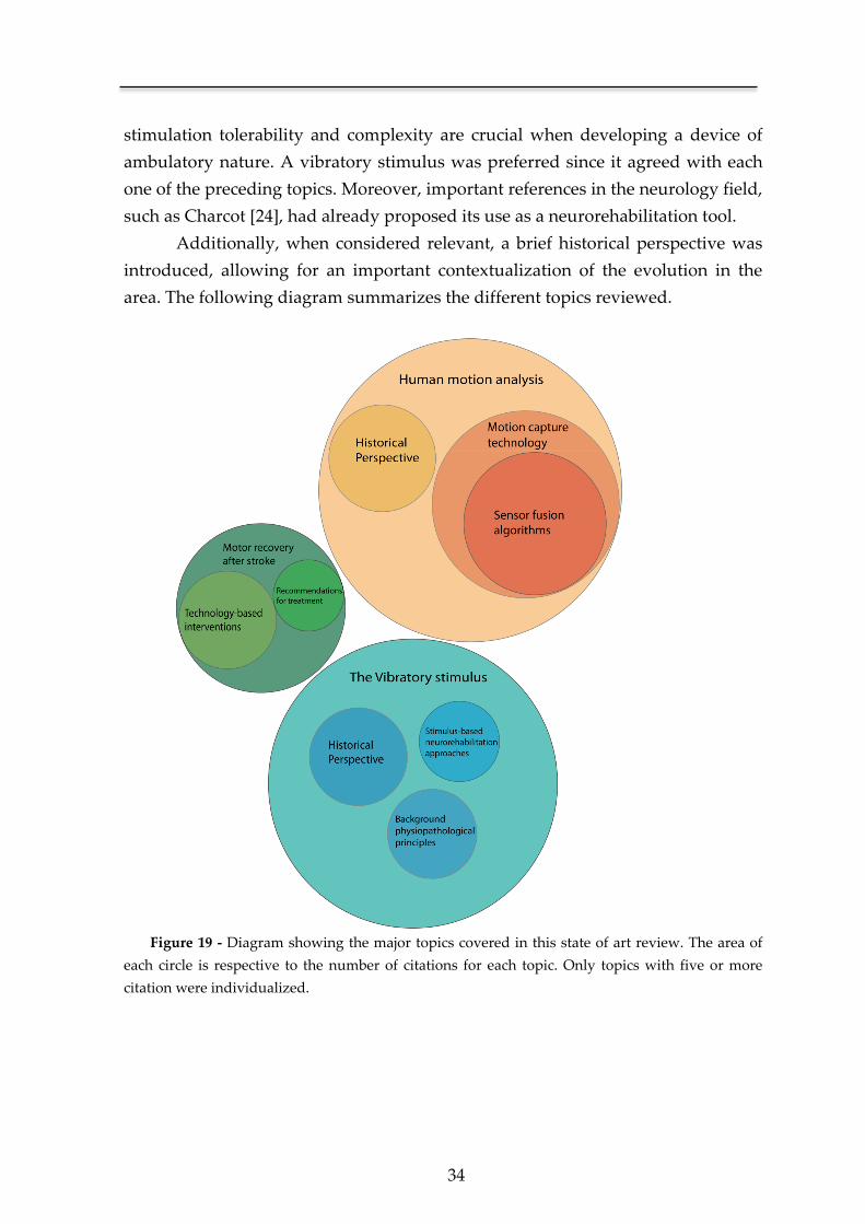
34
stimulation tolerability and complexity are crucial when developing a device of
ambulatory nature. A vibratory stimulus was preferred since it agreed with each
one of the preceding topics. Moreover, important references in the neurology field,
such as Charcot [24], had already proposed its use as a neurorehabilitation tool.
Additionally, when considered relevant, a brief historical perspective was
introduced, allowing for an important contextualization of the evolution in the
area. The following diagram summarizes the different topics reviewed.
Figure 19 - Diagram showing the major topics covered in this state of art review. The area of
each circle is respective to the number of citations for each topic. Only topics with five or more
citation were individualized.
Chapter 3 The Vibratory stimulus as a neurorehabilitation
tool for stroke patients
*Adapted from an original publication:
Bento V. F., Cruz V. T., Ribeiro D. D., Cunha J. P. S
NeuroRehabilitation. 2012 Jan 1; 30(4):287-93.

Chapter 3
36
The use of a vibratory stimulus, either as a haptic interface or as a
neurorehabilitation tool, is subject of an increasing interest from the research
community. The range of possible applications goes from its use as a vibrotactile
training system [105-108], postural stability control [109, 110], floor surfaces [111],
sensory feedback in prosthetic devices [112, 113] and stochastic resonance
paradigms [114, 115].
One of the focus of this thesis is on the use of the vibratory stimulus either as a
neurorehabilitation tool or as a haptic interface. This fact implies that prior to its
clinical use, important properties such as tolerability, safety and comfort must be
first validated. In this context, we devised a stimulation device capable of
delivering an assortment of target vibratory stimuli, modulated in amplitude,
frequency and timing of operation. The stimulation device was designed in a
wearable form towards its ambulatory use. In order to validate the proficiency of
the developed system, a proof-of-concept and tolerability test was performed.
Introductory concepts and state-of-art analysis regarding the use of vibration as a
rehabilitation tool were previously referred in Chapter 2 and therefore will be
omitted in this chapter.
3.1 Methods
3.1.1 Stimulation device
A wearable device was designed and developed for long-term ambulatory use.
Its main function is to deliver targeted external vibratory stimuli as a source of
proprioceptive input to the CNS. The stimuli can be programmed in intensity,
duration, and interval of actuation or can be continuous.
In terms of hardware design, the stimulation device is composed by four main
components: the microcontroller unit, the MOSFET drivers, the two vibration
motors and the power supply (Figure 20).
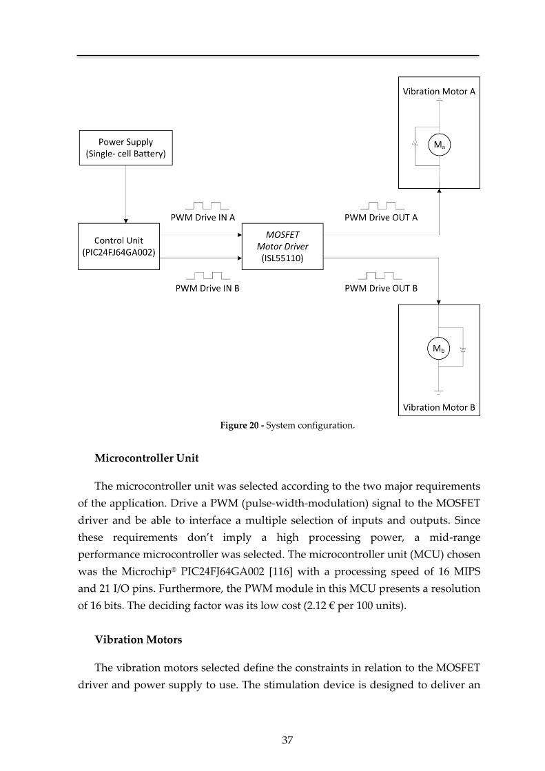
37
Figure 20 - System configuration.
Microcontroller Unit
The microcontroller unit was selected according to the two major requirements
of the application. Drive a PWM (pulse-width-modulation) signal to the MOSFET
driver and be able to interface a multiple selection of inputs and outputs. Since
these requirements don’t imply a high processing power, a mid-range
performance microcontroller was selected. The microcontroller unit (MCU) chosen
was the Microchip® PIC24FJ64GA002 [116] with a processing speed of 16 MIPS
and 21 I/O pins. Furthermore, the PWM module in this MCU presents a resolution
of 16 bits. The deciding factor was its low cost (2.12 € per 100 units).
Vibration Motors
The vibration motors selected define the constraints in relation to the MOSFET
driver and power supply to use. The stimulation device is designed to deliver an
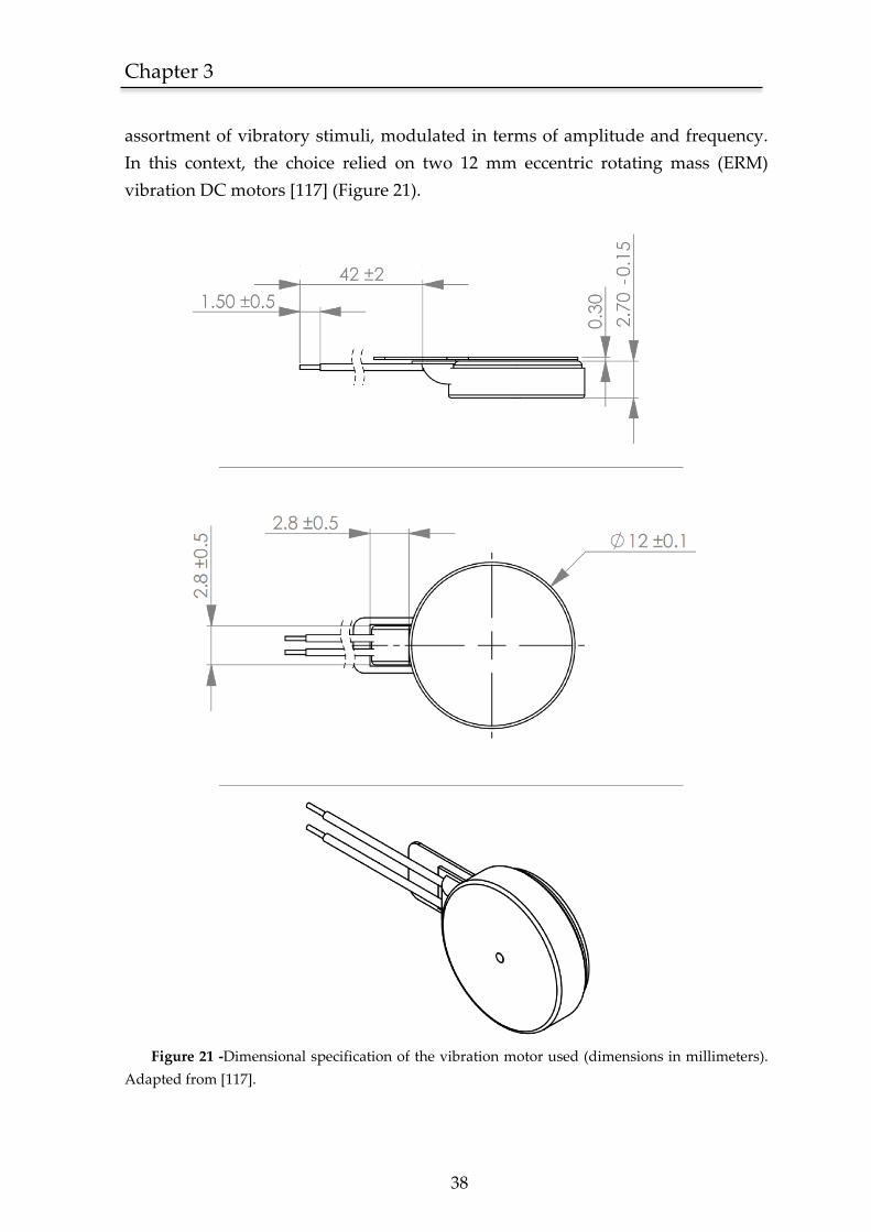
Chapter 3
38
assortment of vibratory stimuli, modulated in terms of amplitude and frequency.
In this context, the choice relied on two 12 mm eccentric rotating mass (ERM)
vibration DC motors [117] (Figure 21).
Figure 21 -Dimensional specification of the vibration motor used (dimensions in millimeters).
Adapted from [117].
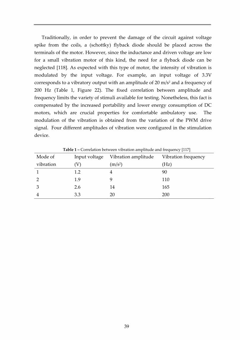
39
Traditionally, in order to prevent the damage of the circuit against voltage
spike from the coils, a (schottky) flyback diode should be placed across the
terminals of the motor. However, since the inductance and driven voltage are low
for a small vibration motor of this kind, the need for a flyback diode can be
neglected [118]. As expected with this type of motor, the intensity of vibration is
modulated by the input voltage. For example, an input voltage of 3.3V
corresponds to a vibratory output with an amplitude of 20 m/s2 and a frequency of
200 Hz (Table 1, Figure 22). The fixed correlation between amplitude and
frequency limits the variety of stimuli available for testing. Nonetheless, this fact is
compensated by the increased portability and lower energy consumption of DC
motors, which are crucial properties for comfortable ambulatory use. The
modulation of the vibration is obtained from the variation of the PWM drive
signal. Four different amplitudes of vibration were configured in the stimulation
device.
Table 1 – Correlation between vibration amplitude and frequency [117]
Mode of
vibration
Input voltage
(V)
Vibration amplitude
(m/s2)
Vibration frequency
(Hz)
1 1.2 4 90
2 1.9 9 110
3 2.6 14 165
4 3.3 20 200
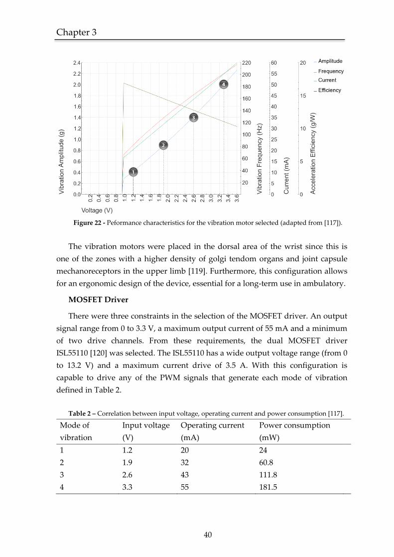
Chapter 3
40
Figure 22 - Peformance characteristics for the vibration motor selected (adapted from [117]).
The vibration motors were placed in the dorsal area of the wrist since this is
one of the zones with a higher density of golgi tendom organs and joint capsule
mechanoreceptors in the upper limb [119]. Furthermore, this configuration allows
for an ergonomic design of the device, essential for a long-term use in ambulatory.
MOSFET Driver
There were three constraints in the selection of the MOSFET driver. An output
signal range from 0 to 3.3 V, a maximum output current of 55 mA and a minimum
of two drive channels. From these requirements, the dual MOSFET driver
ISL55110 [120] was selected. The ISL55110 has a wide output voltage range (from 0
to 13.2 V) and a maximum current drive of 3.5 A. With this configuration is
capable to drive any of the PWM signals that generate each mode of vibration
defined in Table 2.
Table 2 – Correlation between input voltage, operating current and power consumption [117].
Mode of
vibration
Input voltage
(V)
Operating current
(mA)
Power consumption
(mW)
1 1.2 20 24
2 1.9 32 60.8
3 2.6 43 111.8
4 3.3 55 181.5
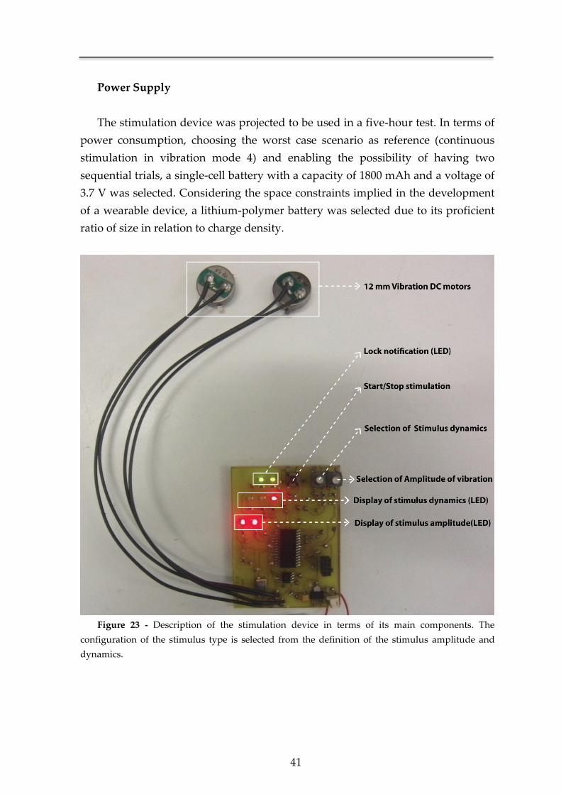
41
Power Supply
The stimulation device was projected to be used in a five-hour test. In terms of
power consumption, choosing the worst case scenario as reference (continuous
stimulation in vibration mode 4) and enabling the possibility of having two
sequential trials, a single-cell battery with a capacity of 1800 mAh and a voltage of
3.7 V was selected. Considering the space constraints implied in the development
of a wearable device, a lithium-polymer battery was selected due to its proficient
ratio of size in relation to charge density.
Figure 23 - Description of the stimulation device in terms of its main components. The
configuration of the stimulus type is selected from the definition of the stimulus amplitude and
dynamics.
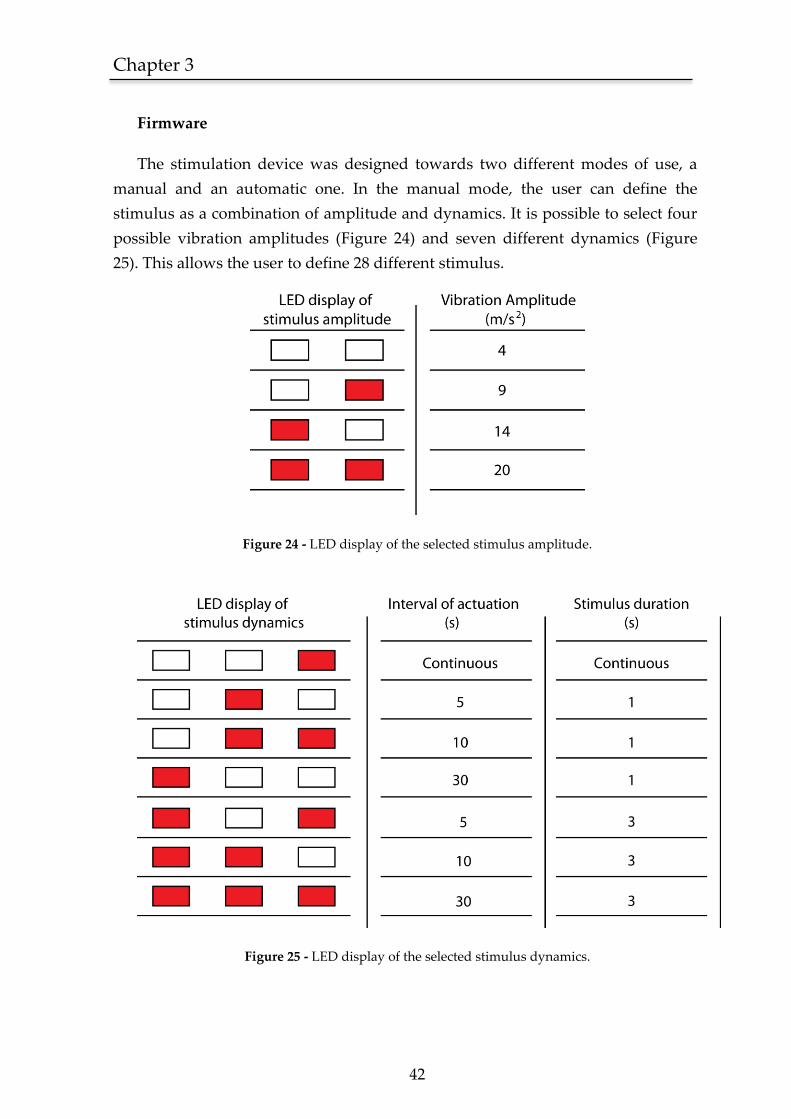
Chapter 3
42
Firmware
The stimulation device was designed towards two different modes of use, a
manual and an automatic one. In the manual mode, the user can define the
stimulus as a combination of amplitude and dynamics. It is possible to select four
possible vibration amplitudes (Figure 24) and seven different dynamics (Figure
25). This allows the user to define 28 different stimulus.
Figure 24 - LED display of the selected stimulus amplitude.
Figure 25 - LED display of the selected stimulus dynamics.
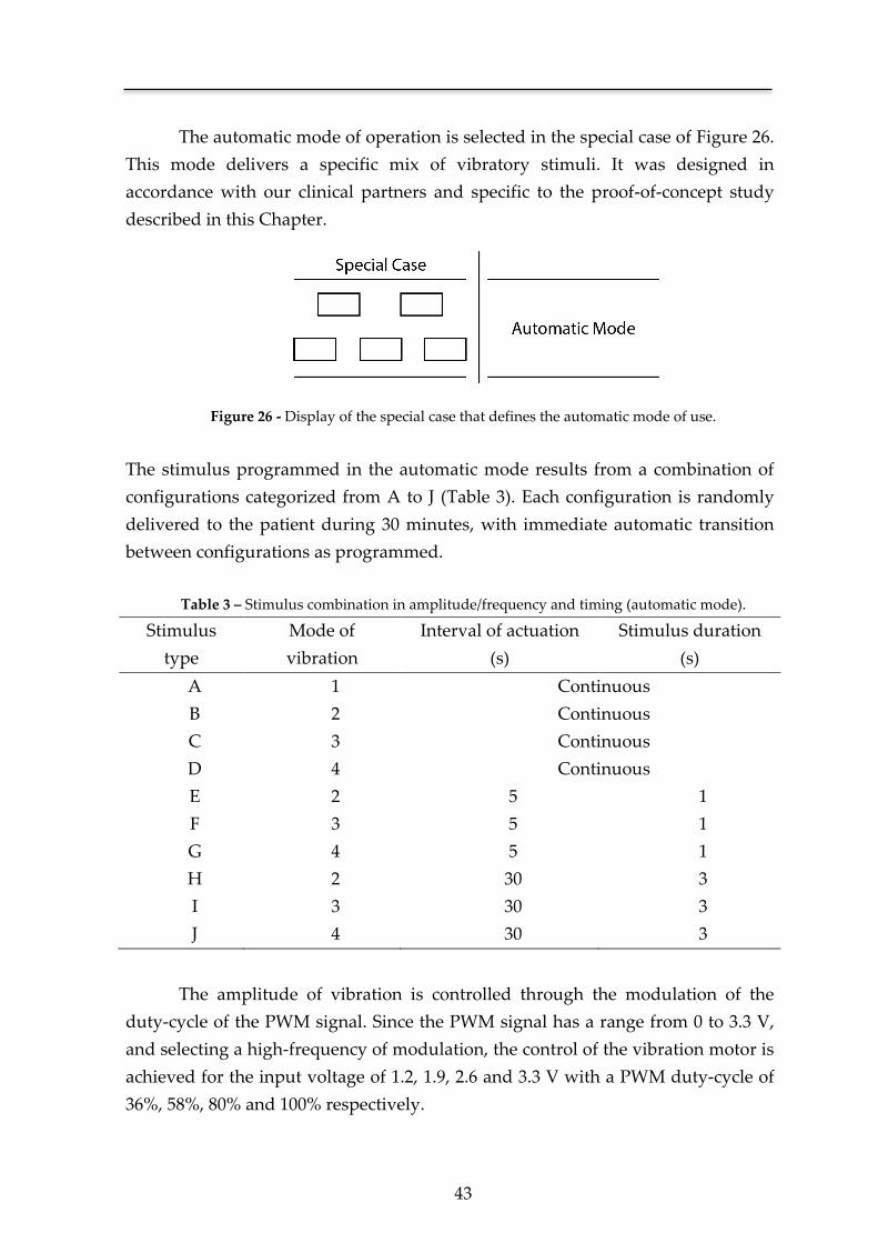
43
The automatic mode of operation is selected in the special case of Figure 26.
This mode delivers a specific mix of vibratory stimuli. It was designed in
accordance with our clinical partners and specific to the proof-of-concept study
described in this Chapter.
Figure 26 - Display of the special case that defines the automatic mode of use.
The stimulus programmed in the automatic mode results from a combination of
configurations categorized from A to J (Table 3). Each configuration is randomly
delivered to the patient during 30 minutes, with immediate automatic transition
between configurations as programmed.
Table 3 – Stimulus combination in amplitude/frequency and timing (automatic mode).
Stimulus
type
Mode of
vibration
Interval of actuation
(s)
Stimulus duration
(s)
A 1 Continuous
B 2 Continuous
C 3 Continuous
D 4 Continuous
E 2 5 1
F 3 5 1
G 4 5 1
H 2 30 3
I 3 30 3
J 4 30 3
The amplitude of vibration is controlled through the modulation of the
duty-cycle of the PWM signal. Since the PWM signal has a range from 0 to 3.3 V,
and selecting a high-frequency of modulation, the control of the vibration motor is
achieved for the input voltage of 1.2, 1.9, 2.6 and 3.3 V with a PWM duty-cycle of
36%, 58%, 80% and 100% respectively.
Chapter 3
44
In order to avoid an unwanted change in configuration during the trial, a
lock system was programmed and contemplated in both operative modes (manual
and automatic). This way, after the device has been powered on, the user has 30
seconds to define the stimulus and/or mode of operation. After the device has
been locked on, the selection of modes is disabled.
3.1.2 Patient selection
Patients were selected from the stroke unit upon referral by their stroke
physician. They were in an early post stroke period but medically stable, already
able to sit and enrolled in a rehabilitation program that included daily periods
outside the ward. The recruitment occurred over a one-month period and patients
fulfilled all the following criteria:
a. Having a first ever middle cerebral artery (MCA) ischemic stroke with a
motor deficit defined as a score of at least two points on items five and
six of the National Institute of Health Stroke Scale (NIHSS);
b. Being previously independent, defined as having a modified Rankin
scale (mRS) of 0;
c. Without severe aphasia or other cognitive or psychiatric comorbidity
that impaired communication.
All patients and caregivers understood the purpose of the study and provided
written informed consent. Approval from the referring stroke physician was also
obtained prior to enrollment in the experiments. This study was approved by the
hospital review board and ethics commission.
Five stroke patients were enrolled, three male and two female, aged between
43 and 71 years. Three had a left MCA ischemic stroke, and all showed cortical
and subcortical involvement on CT/MRI scans. Two patients had visual and
sensitive neglect. Motor deficits dominated in all and were severe but were not
hemiplegia (NIHSS between 11 and 14). The test occurred between five and 14
days after disease onset.
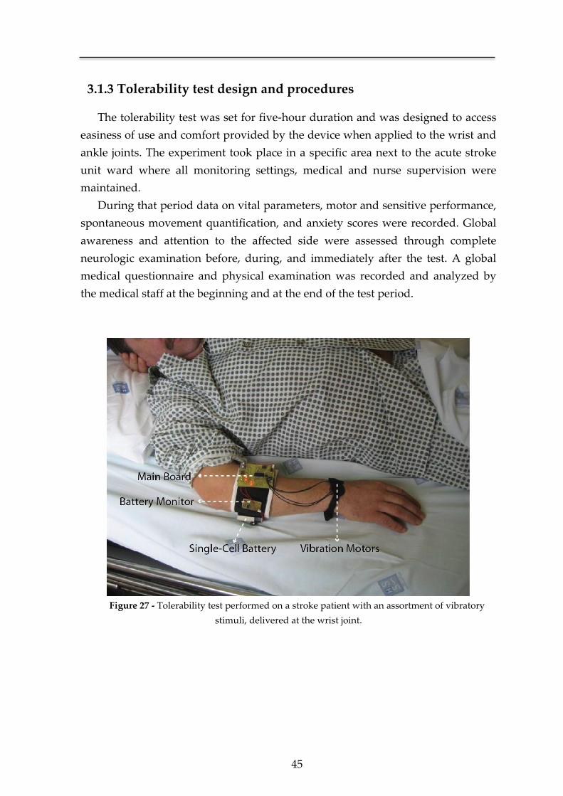
45
3.1.3 Tolerability test design and procedures
The tolerability test was set for five-hour duration and was designed to access
easiness of use and comfort provided by the device when applied to the wrist and
ankle joints. The experiment took place in a specific area next to the acute stroke
unit ward where all monitoring settings, medical and nurse supervision were
maintained.
During that period data on vital parameters, motor and sensitive performance,
spontaneous movement quantification, and anxiety scores were recorded. Global
awareness and attention to the affected side were assessed through complete
neurologic examination before, during, and immediately after the test. A global
medical questionnaire and physical examination was recorded and analyzed by
the medical staff at the beginning and at the end of the test period.
Figure 27 - Tolerability test performed on a stroke patient with an assortment of vibratory
stimuli, delivered at the wrist joint.
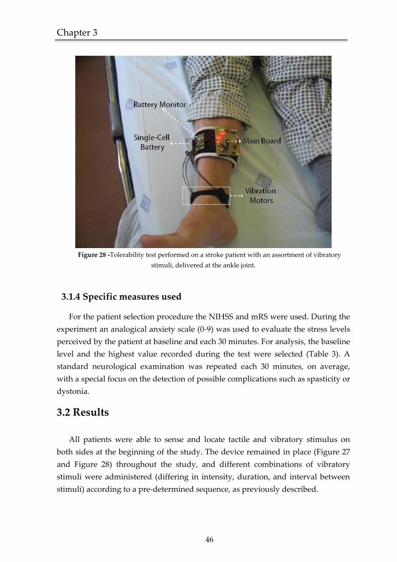
Chapter 3
46
Figure 28 -Tolerability test performed on a stroke patient with an assortment of vibratory
stimuli, delivered at the ankle joint.
3.1.4 Specific measures used
For the patient selection procedure the NIHSS and mRS were used. During the
experiment an analogical anxiety scale (0-9) was used to evaluate the stress levels
perceived by the patient at baseline and each 30 minutes. For analysis, the baseline
level and the highest value recorded during the test were selected (Table 3). A
standard neurological examination was repeated each 30 minutes, on average,
with a special focus on the detection of possible complications such as spasticity or
dystonia.
3.2 Results
All patients were able to sense and locate tactile and vibratory stimulus on
both sides at the beginning of the study. The device remained in place (Figure 27
and Figure 28) throughout the study, and different combinations of vibratory
stimuli were administered (differing in intensity, duration, and interval between
stimuli) according to a pre-determined sequence, as previously described.
47
None of the patients or relatives asked to interrupt the tolerability test, and
there were no records of pain, discomfort, cardiovascular instability, or extreme
anxiety. The analogical anxiety scores were low at baseline and did not increase
during the experiment except for one patient with a one-point increase in a nine-
point scale. Patients were able to sense the stimulus appropriately and
discriminate between different intensities and stimulation intervals, either when
building up or decreasing. Visual attention toward the affected side immediately
upon stimulation was recorded in four patients. A subjective but clear increase in
global awareness was recorded in two patients during stimulation, as assessed by
the neurologic examination. This finding subsided after the trial. There were no
records of dystonia or increased spasticity during the trial or the ensuing days.
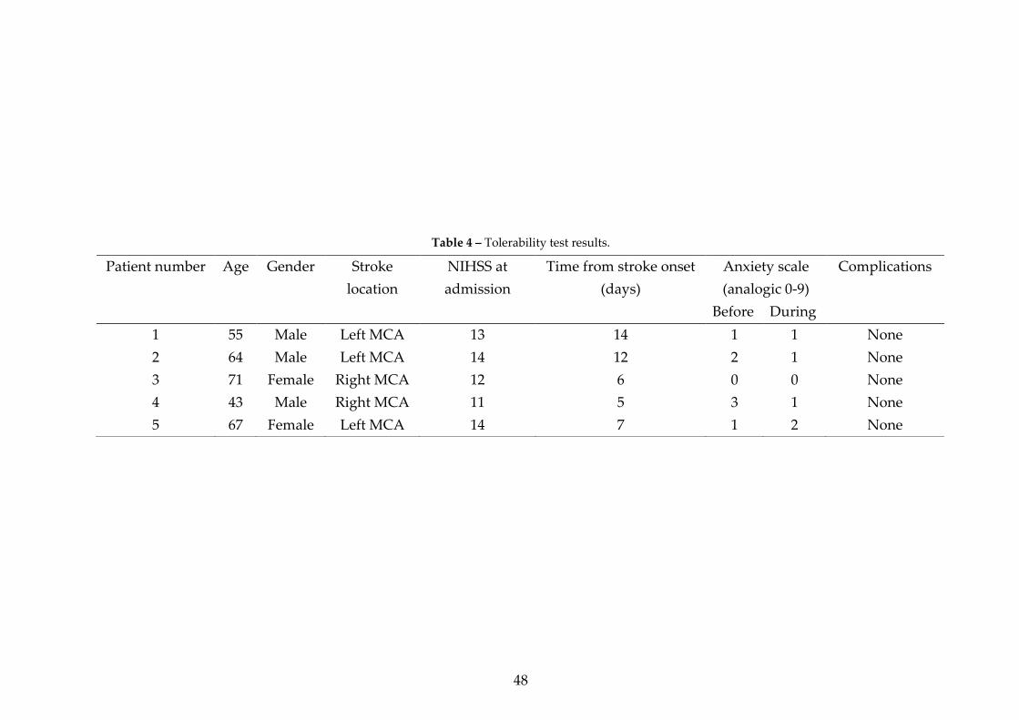
48
Table 4 – Tolerability test results.
Patient number Age Gender Stroke
location
NIHSS at
admission
Time from stroke onset
(days)
Anxiety scale
(analogic 0-9)
Complications
Before During
1 55 Male Left MCA 13 14 1 1 None
2 64 Male Left MCA 14 12 2 1 None
3 71 Female Right MCA 12 6 0 0 None
4 43 Male Right MCA 11 5 3 1 None
5 67 Female Left MCA 14 7 1 2 None
49
3.3 Discussion
To our knowledge, this is the first tolerability test focused on the use of
targeted vibratory stimulus as a neurorehabilitation tool applied to acute stroke
patients.
The prototype used remained in place in a ward setting and was energy
sufficient during a five hour operation. Despite the long period of consecutive
stimulation achieved in all the patients, there were no complications to report
during an early post-stroke setting. Confirming our initial assumptions, the
majority of patients increased their attention towards the affected side during
stimulation, and two were reported as clearly more awake during the test.
The sample size was very small which constitutes a limitation of this exploratory
study. Furthermore there were no data on cortical activation patterns during the
various stimulus arrays which hinders any inference on which of the available
patterns of stimulation is best. These issues will be addressed further in future
studies, under functional MRI control and over intensive daily long-term use,
during the ensuing pilot trial to access the efficacy of this neurorehabilitation
approach.
Considering our primary goals and the limitations of this study, the present
results favor the feasibility of the delivery of vibratory stimuli with the intent to
foster cortical remaping through preserved sensory aferences [9, 10, 12, 39, 45] in
an early post stroke setting. The increased levels of global awareness and attention
towards the side of the body may represent an indirect measure of cortical
activation [34, 35, 37], essential for neuroplasticity and modulation of
rehabilitation processes [9, 39]. These findings may be comparable to what
happens with proprioceptive stimulation in hemi-negligence and anosognosia
models [8] and justify special attention in the pilot trial.
An important strength of the approach designed and the development of a
low cost wearable device is that it can be easily combined with standard therapy
in a large number of patients, unlike expensive, high-tech solutions [6, 7]. This
characteristic will be of great value when conducting a properly sized multicenter
case-control study to evaluate this approach.
Chapter 3
50
3.4 Conclusion
Current scientific knowledge reinforces that successful reorganization of
surviving nervous tissue supports cognitive and motor recovery after stroke. The
development of new neurorehabilitation tools to modulate this physiologic
process is needed. In this context, vibratory stimuli are a noninvasive form of
proprioceptive stimulation of the nervous system and are freely available and easy
to use at a low cost. In Chapter 3 we describe the development of a novel
stimulation device and its proof-of-concept, in a study designed to access the
feasibility and tolerability of targeted vibratory stimuli delivered through this
wearable device in an early post-stroke setting.
Five stroke patients were recruited from a stroke unit setting having a first ever
medial cerebral artery ischemic stroke with motor deficit. The stimulation device
developed delivered external vibratory stimuli to major joints at preprogrammed
arrays of intensity, duration and interval of actuation. The tolerability test was set
for five-hour duration and during that period data on vital parameters, cognitive,
motor and sensitive performance as well as anxiety scores were recorded.
The device remained in place throughout the totality of each trial and none of
the patients or relatives asked to interrupt the tolerability test. There were no
major complications during the trial or the ensuing days. Attention to the affected
side during stimulation was increased in four patients, and two were reported as
clearly more awake during the test.
This is the first tolerability test focused on the use of targeted vibratory
stimulus as a neurorehabilitation tool in stroke patients. There were no hazards to
report and most interestingly the majority of patients showed increased awareness
to the affected side of the body. These findings will be further analyzed under
functional MRI control and on long-term ambulatory use trials.


Chapter 4 The SWORD device*
* Adapted from an original publication at the 33rd Annual International
Conference of the IEEE Engineering in Medicine and Biology Society
(EMBC ’11), where it received the “Highest Future Impact” award.
Aug. 30 2011-Sept. 3 2011, Boston, USA

Chapter 4
52
In spite of the growing interest verified in the field of technology-based
interventions for Stroke rehabilitation, there is still to appear a global solution that
is both successful and suitable for a widespread use [12, 21].
In this Chapter we present a novel rehabilitation tool designed to be used in
ambulatory and developed towards the motor recovery of the patient’s upper-
limb. The SWORD device combines a movement quantification system that
analysis the quality of the motor task performed with a haptic interface
responsible for providing a direct feedback to the patient. When combined with a
computer or smartphone, the SWORD device evolves into a complete tele-
rehabilitation system that enables a direct connection between clinical and
ambulatory settings, upgrading the feedback provided into a combined form of
haptic and visual interface.
An experimental study was designed to assess the effectiveness of the
SWORD device in 5 participants. Results show that, for 4 in 5 participants, the use
of the SWORD device promoted a clear increase in the intensity and quality of
training. This preliminary data confirms the SWORD device as a rehabilitation
tool capable of providing an intervention that follows the three golden rules of
motor recovery in Stroke patients: high-intensity, repetitive task-specific practice
and feedback on performance [21]. The promising nature of these results must be
complemented with a larger clinical trial designed to assess the proficiency of the
SWORD device in the restoration of motor function, during the first three months
after a Stroke.
4.1 Introduction
As can be depicted in the review of the current state-of-art in Chapter 2,
technology-based interventions in Stroke rehabilitation tackle two main research
lines, each one subject of a burgeoning interest from the research community.
Robotic-Assisted therapies (also known as rehabilitation robotics), have been
proved to be of valid use in the recovery of upper-limb motor function. The 2010
American Heart Association guidelines for stroke care [121] already recommend
its use as valid therapy for upper-limb rehabilitation. One of the references in this
area, the MIT-MANUS system [122], has been in development for about 20 years
by the team of Hermano I. Krebs (the first article describing the system is dated
back to 1992 [123]). The MIT-MANUS (Figure 29) is a robotic joystick that guides
the movement of the patient when he tries to perform a specific motor task with its
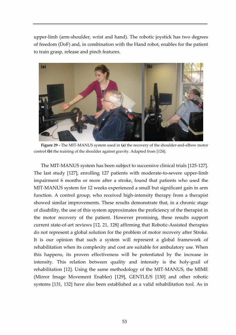
53
upper-limb (arm-shoulder, wrist and hand). The robotic joystick has two degrees
of freedom (DoF) and, in combination with the Hand robot, enables for the patient
to train grasp, release and pinch features.
Figure 29 - The MIT-MANUS system used in (a) the recovery of the shoulder-and-elbow motor
control (b) the training of the shoulder against gravity. Adapted from [124].
The MIT-MANUS system has been subject to successive clinical trials [125-127].
The last study [127], enrolling 127 patients with moderate-to-severe upper-limb
impairment 6 months or more after a stroke, found that patients who used the
MIT-MANUS system for 12 weeks experienced a small but significant gain in arm
function. A control group, who received high-intensity therapy from a therapist
showed similar improvements. These results demonstrate that, in a chronic stage
of disability, the use of this system approximates the proficiency of the therapist in
the motor recovery of the patient. However promising, these results support
current state-of-art reviews [12, 21, 128] affirming that Robotic-Assisted therapies
do not represent a global solution for the problem of motor recovery after Stroke.
It is our opinion that such a system will represent a global framework of
rehabilitation when its complexity and cost are suitable for ambulatory use. When
this happens, its proven effectiveness will be potentiated by the increase in
intensity. This relation between quality and intensity is the holy-grail of
rehabilitation [12]. Using the same methodology of the MIT-MANUS, the MIME
(Mirror Image Movement Enabler) [129], GENTLE/S [130] and other robotic
systems [131, 132] have also been established as a valid rehabilitation tool. As in
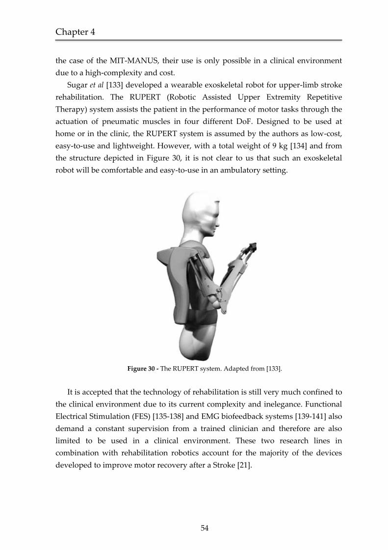
Chapter 4
54
the case of the MIT-MANUS, their use is only possible in a clinical environment
due to a high-complexity and cost.
Sugar et al [133] developed a wearable exoskeletal robot for upper-limb stroke
rehabilitation. The RUPERT (Robotic Assisted Upper Extremity Repetitive
Therapy) system assists the patient in the performance of motor tasks through the
actuation of pneumatic muscles in four different DoF. Designed to be used at
home or in the clinic, the RUPERT system is assumed by the authors as low-cost,
easy-to-use and lightweight. However, with a total weight of 9 kg [134] and from
the structure depicted in Figure 30, it is not clear to us that such an exoskeletal
robot will be comfortable and easy-to-use in an ambulatory setting.
Figure 30 - The RUPERT system. Adapted from [133].
It is accepted that the technology of rehabilitation is still very much confined to
the clinical environment due to its current complexity and inelegance. Functional
Electrical Stimulation (FES) [135-138] and EMG biofeedback systems [139-141] also
demand a constant supervision from a trained clinician and therefore are also
limited to be used in a clinical environment. These two research lines in
combination with rehabilitation robotics account for the majority of the devices
developed to improve motor recovery after a Stroke [21].
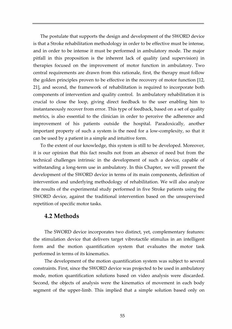
55
The postulate that supports the design and development of the SWORD device
is that a Stroke rehabilitation methodology in order to be effective must be intense,
and in order to be intense it must be performed in ambulatory mode. The major
pitfall in this proposition is the inherent lack of quality (and supervision) in
therapies focused on the improvement of motor function in ambulatory. Two
central requirements are drawn from this rationale, first, the therapy must follow
the golden principles proven to be effective in the recovery of motor function [12,
21], and second, the framework of rehabilitation is required to incorporate both
components of intervention and quality control. In ambulatory rehabilitation it is
crucial to close the loop, giving direct feedback to the user enabling him to
instantaneously recover from error. This type of feedback, based on a set of quality
metrics, is also essential to the clinician in order to perceive the adherence and
improvement of his patients outside the hospital. Paradoxically, another
important property of such a system is the need for a low-complexity, so that it
can be used by a patient in a simple and intuitive form.
To the extent of our knowledge, this system is still to be developed. Moreover,
it is our opinion that this fact results not from an absence of need but from the
technical challenges intrinsic in the development of such a device, capable of
withstanding a long-term use in ambulatory. In this Chapter, we will present the
development of the SWORD device in terms of its main components, definition of
intervention and underlying methodology of rehabilitation. We will also analyze
the results of the experimental study performed in five Stroke patients using the
SWORD device, against the traditional intervention based on the unsupervised
repetition of specific motor tasks.
4.2 Methods
The SWORD device incorporates two distinct, yet, complementary features:
the stimulation device that delivers target vibrotactile stimulus in an intelligent
form and the motion quantification system that evaluates the motor task
performed in terms of its kinematics.
The development of the motion quantification system was subject to several
constraints. First, since the SWORD device was projected to be used in ambulatory
mode, motion quantification solutions based on video analysis were discarded.
Second, the objects of analysis were the kinematics of movement in each body
segment of the upper-limb. This implied that a simple solution based only on

Chapter 4
56
accelerometer data [142-145] did not comprise with the objective of estimating the
position of the upper-limb in each time instant. Third, the SWORD device should
be easy to wear, easy to set up and provide a maximum comfort to the patient,
therefore, solutions based on goniometers [146, 147] were also discarded. These
three constraints defined that the motion quantification system should be based on
MARG sensors. This solution is portable, easy to calibrate and thus easy to set up.
Additionally, it was proved to be accurate in diverse applications [104, 148, 149].
4.2.1 Intervention definition
The SWORD device was designed to address the three major requirements
for an efficient rehabilitation therapy: high-intensity, feedback on performance
and repetitive task-specific practice. From these requirements, the intervention
based on the use of the SWORD device follows the ensuing methodology:
i. The patient trains in the clinical environment a set of specific
motor tasks with the aid of the clinical staff.
ii. In ambulatory mode, the patient performs these motor tasks
using the SWORD device.
iii. The SWORD device delivers a vibratory stimulus to the patient if
he does not perform a correct movement in a time-window
defined by the clinician (haptic interface).
iv. The actuation of the stimulus is continuous until a correct
movement is detected.
v. The SWORD device records the kinematic data relative to the
execution of the specific motor task.
vi. The data is analyzed by the clinician and an automatic evaluation
of the intensity and quality of the rehabilitation at home is
performed.
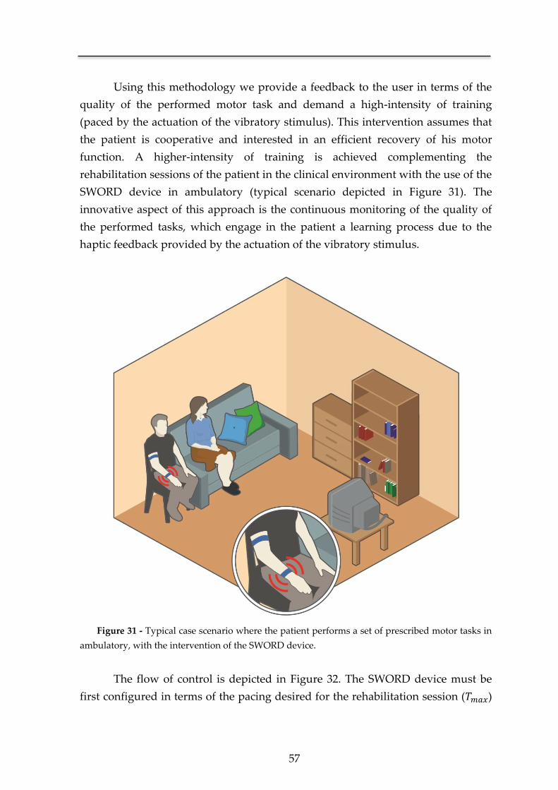
57
Using this methodology we provide a feedback to the user in terms of the
quality of the performed motor task and demand a high-intensity of training
(paced by the actuation of the vibratory stimulus). This intervention assumes that
the patient is cooperative and interested in an efficient recovery of his motor
function. A higher-intensity of training is achieved complementing the
rehabilitation sessions of the patient in the clinical environment with the use of the
SWORD device in ambulatory (typical scenario depicted in Figure 31). The
innovative aspect of this approach is the continuous monitoring of the quality of
the performed tasks, which engage in the patient a learning process due to the
haptic feedback provided by the actuation of the vibratory stimulus.
Figure 31 - Typical case scenario where the patient performs a set of prescribed motor tasks in
ambulatory, with the intervention of the SWORD device.
The flow of control is depicted in Figure 32. The SWORD device must be
first configured in terms of the pacing desired for the rehabilitation session ( )
Chapter 4
58
and the motor tasks that are object of evaluation. If one of the prescribed motor
tasks was detected by the system as correctly performed, the flag CM is set and the
actuation of the vibratory stimulus is ceased. After seconds, if the patient
didn’t perform any movement or if the motor task was incorrectly executed
(CM=0), the system delivers a vibrotactile stimulus to alert the patient of that
situation. The delivery of the stimulus is only ceased after the detection of a
correct execution (CM=1).
Figure 32 – Operational flow of the SWORD device conceptualized in an UML state machine
diagram [150]. The flag CM (Correct Movement) is set if a movement (decided as correctly
performed) was detected. The variable is relative to the maximum interval of time for the
system to detect a correct movement. If no correct movement was performed in that interval
( ), the system delivers a vibrotactile stimulus.
Another important property of the SWORD device is the continuous
acquisition of the kinematic data during the training session. This data is
composed by the three-dimensional position of the elbow and wrist joints in each
time instant. From these dynamics the clinician is able to document in a precise
and continuous form the improvement of the patient. Movement quality
kinematic variables such as smoothness and joint-synergies have already been
demonstrated to be of valid use in regular clinical practice [74].

59
4.2.2 Movement Quantification System
The central element of the SWORD device is its movement quantification
system that, as previously described, allows for a continuous analysis of the
patient’s performance. The movement quantification system is structured
according to three main blocks, the sensor fusion algorithm, the human kinematics
model and the sub-system responsible for comparing the motion dynamics of the
performed motor task with the quality metrics of reference.
Sensor Fusion Algorithm
The proficiency of such a system is highly dependent on the sensor fusion
algorithm developed towards the estimation of the kinematics of rotation. The
reference frame of the strapdown MARG sensor unit is denoted as body-frame {B}.
The kinematics of rotation are defined in terms of the earth-frame {E} in relation to
the body-frame {B} (Figure 33).
Figure 33 - Definition of each frame of reference. The rotation matrix R, describes the
kinematics of the rotation from the body-frame towards the earth-frame. The rotation referenced to
each axis xe, ye and ze is respectively designated as roll (φ), pitch (θ) and yaw (ψ).
The object of estimation is the rotation matrix that describes the
relative orientation of {B} in respect to {E}. is a 3x3 matrix defined as,
Chapter 4
60
[
]
[
] [
]
[
] [
]
Where represents the inverse of the rotation matrix , such that,
The estimation of is performed through the fusion of the 3-axis rate gyroscope,
3-axis accelerometer and 3-axis magnetometer measures. Each gyroscope
measurement is modeled as,
=
⟨ ⟩
where the true value of is distorted by a slowly time-varying bias and a
white noise term . is composed by its single components , and that
respectively represent the angular velocity in relation to the x, y and z-axis.
Each 3-axis accelerometer measure represents the linear acceleration of the
sensor unit in the body-frame {B} in relation to the earth-frame {E}. Due to the
configuration of a MEMS accelerometer (denoted in Chapter 2), the accelerometer
measures will also include the component of acceleration given by the
gravitational field ( ).
( )
⟨ ⟩
61
Where is the measured acceleration at the body-frame of reference. Analogous
to the gyroscope error model, each accelerometer measure will also be corrupted
by a bias term and a white noise term . The true value of the acceleration,
given by , is composed by the single components of , and that are
respective to the acceleration sensed in the x, y and z-axis.
The 3-axis magnetometer is used to sense the magnetic field in the body-
frame. Each measure of the magnetic field at the body-frame ( ), will be
composed by the sum of the earth magnetic field ( , expressed in the earth-
frame), a disturbance vector and white noise term .
⟨ ⟩
The sensor fusion algorithm used to estimate based on the measures of
and , was adapted from the work by Mahony et al [102]. The estimation
algorithm proposed in [102] was developed towards the attitude estimation of an
UAV and solely based on accelerometer and gyroscope measures. Some
adaptations were necessary in order to implement it in a human quantification
system leading to a novel algorithm specifically designed for the specificities of
human motion capture. One example of such adaptation is the description of the
rotation in terms of quaternions in order to avoid the singularities present when
using Euler angles (e.g. gimbal lock). Other important modification is the inclusion
of the magnetometer measures ( ) in the estimation process in order to obtain an
error-free orientation in all three-axis of rotation.
The estimation of the matrix R is simplified if we formulate the problem on the
special orthogonal group ( ), so that for any matrix ,
( ) { | }
Where represents the transpose of matrix .
The use of an orthogonal matrix to describe the kinematics of rotation also implies
that,
Chapter 4
62
and the kinematics of rotation between the earth-frame and the body-frame can be
described as,
( ) ( ) ( )
Where the differential equation is in the form of,
( )
( ) ( )
and ( ) is the angular velocity matrix, that is updated from the gyroscope
measurements,
( ) [
]
Assuming that the orientation matrix is updated every , and that is of small
value, the integration of ( ) can be approximated by,
( ) ( ) ( ) ( )
Where ( ) is the estimated rotation matrix at the time instant .
If each measured sample of the gyroscope represented the true value for the
angular velocity, no further steps were needed in the estimation of the rotation
between the earth-frame and the body-frame. However, since that is not the case,
there is the need to compensate each measure present in ( ) with the error-
independent information from the 3-axis accelerometer and 3-axis magnetometer.
Figure 34 depicts the global model of the sensor fusion algorithm. The error
vector ( ) represents the difference between the predicted orientation
obtained from the numerical integration of ( ), and the orientation retrieved
from and .
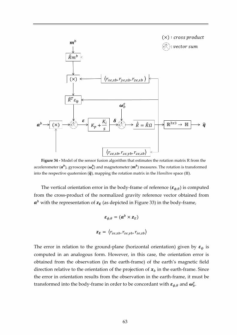
63
Figure 34 - Model of the sensor fusion algorithm that estimates the rotation matrix R from the
accelerometer ( ), gyroscope ( ) and magnetometer ( ) measures. The rotation is transformed
into the respective quaternion ( ), mapping the rotation matrix in the Hamilton space (ℍ).
The vertical orientation error in the body-frame of reference ( ) is computed
from the cross-product of the normalized gravity reference vector obtained from
with the representation of (as depicted in Figure 33) in the body-frame,
( )
⟨ ⟩
The error in relation to the ground-plane (horizontal orientation) given by is
computed in an analogous form. However, in this case, the orientation error is
obtained from the observation (in the earth-frame) of the earth’s magnetic field
direction relative to the orientation of the projection of in the earth-frame. Since
the error in orientation results from the observation in the earth-frame, it must be
transformed into the body-frame in order to be concordant with and .
Chapter 4
64
The correction vector is generated applying the error vector to the
proportional-integral block,
∫
where and are respectively proportional and integral gains defined to
minimize the error present in each measured sample of the angular velocity.
The estimate at the time instant ( ) is obtained through the compensated
angular velocity matrix,
( ) [
( ) ( )
( ) ( )
]
Finally, the use of a rotation matrix to describe an orientation in space is inefficient
in terms of data transmission. Therefore, each rotation matrix ( ) is converted
into its quaternion representation, as follows,
⟨ ⟩
Since each quaternion is a four-dimensional complex number, the gain in
efficiency is trivial when compared against a 3x3 rotation matrix. Additionally, the
use of quaternions is independent of the coordinate system used and eliminates
the occurrence of the phenomenon of gimbal lock, innate to the representation of
Euler angles [151].
Human Kinematics Model
The SWORD device is defined as a global motor neurorehabilitation tool. The
work herein presented shows the particular case of the SWORD device, devised to
tackle the motor recovery of a patient’s upper-limb. Therefore, the human
kinematics model is focused on the estimation of the orientation and position of
two body segments, the arm and forearm, and three major joints: shoulder, elbow
and wrist. Each strapdown module estimates the rotation of a generic vector in
relation to the earth-frame. In order to estimate the three-dimensional position of
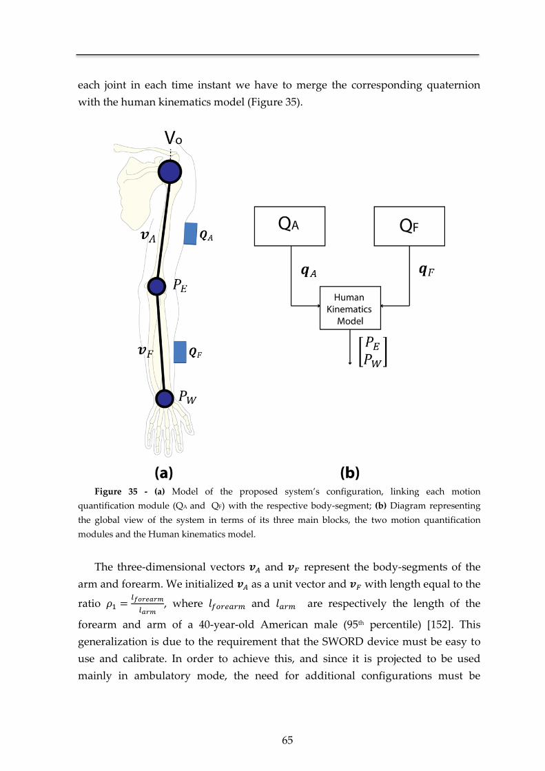
65
each joint in each time instant we have to merge the corresponding quaternion
with the human kinematics model (Figure 35).
Figure 35 - (a) Model of the proposed system’s configuration, linking each motion
quantification module (QA and QF) with the respective body-segment; (b) Diagram representing
the global view of the system in terms of its three main blocks, the two motion quantification
modules and the Human kinematics model.
The three-dimensional vectors and represent the body-segments of the
arm and forearm. We initialized as a unit vector and with length equal to the
ratio
, where and are respectively the length of the
forearm and arm of a 40-year-old American male (95th percentile) [152]. This
generalization is due to the requirement that the SWORD device must be easy to
use and calibrate. In order to achieve this, and since it is projected to be used
mainly in ambulatory mode, the need for additional configurations must be
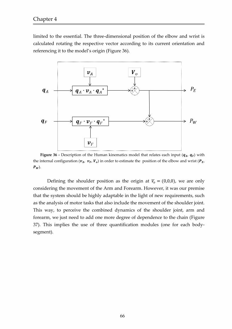
Chapter 4
66
limited to the essential. The three-dimensional position of the elbow and wrist is
calculated rotating the respective vector according to its current orientation and
referencing it to the model’s origin (Figure 36).
Figure 36 - Description of the Human kinematics model that relates each input ( , ) with
the internal configuration ( , , ) in order to estimate the position of the elbow and wrist ( ,
).
Defining the shoulder position as the origin at ( ), we are only
considering the movement of the Arm and Forearm. However, it was our premise
that the system should be highly adaptable in the light of new requirements, such
as the analysis of motor tasks that also include the movement of the shoulder joint.
This way, to perceive the combined dynamics of the shoulder joint, arm and
forearm, we just need to add one more degree of dependence to the chain (Figure
37). This implies the use of three quantification modules (one for each body-
segment).
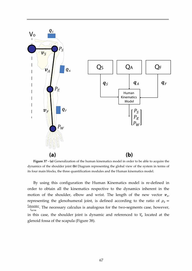
67
Figure 37 - (a) Generalization of the human kinematics model in order to be able to acquire the
dynamics of the shoulder joint (b) Diagram representing the global view of the system in terms of
its four main blocks, the three quantification modules and the Human kinematics model.
By using this configuration the Human Kinematics model is re-defined in
order to obtain all the kinematics respective to the dynamics inherent in the
motion of the shoulder, elbow and wrist. The length of the new vector ,
representing the glenohumeral joint, is defined according to the ratio of
. The necessary calculus is analogous for the two-segments case, however,
in this case, the shoulder joint is dynamic and referenced to located at the
glenoid fossa of the scapula (Figure 38).
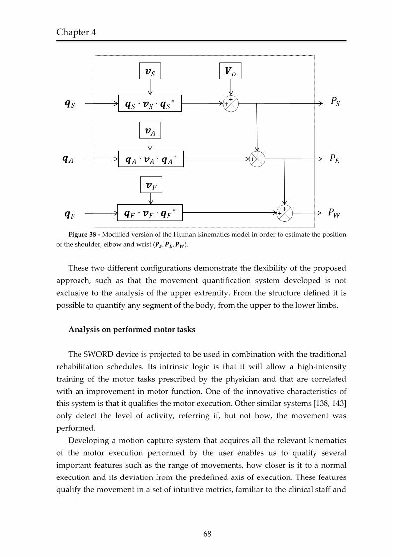
Chapter 4
68
Figure 38 - Modified version of the Human kinematics model in order to estimate the position
of the shoulder, elbow and wrist ( ).
These two different configurations demonstrate the flexibility of the proposed
approach, such as that the movement quantification system developed is not
exclusive to the analysis of the upper extremity. From the structure defined it is
possible to quantify any segment of the body, from the upper to the lower limbs.
Analysis on performed motor tasks
The SWORD device is projected to be used in combination with the traditional
rehabilitation schedules. Its intrinsic logic is that it will allow a high-intensity
training of the motor tasks prescribed by the physician and that are correlated
with an improvement in motor function. One of the innovative characteristics of
this system is that it qualifies the motor execution. Other similar systems [138, 143]
only detect the level of activity, referring if, but not how, the movement was
performed.
Developing a motion capture system that acquires all the relevant kinematics
of the motor execution performed by the user enables us to qualify several
important features such as the range of movements, how closer is it to a normal
execution and its deviation from the predefined axis of execution. These features
qualify the movement in a set of intuitive metrics, familiar to the clinical staff and
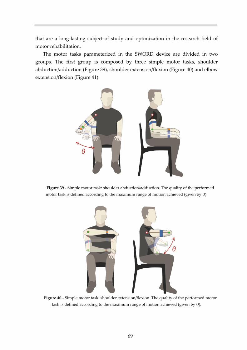
69
that are a long-lasting subject of study and optimization in the research field of
motor rehabilitation.
The motor tasks parameterized in the SWORD device are divided in two
groups. The first group is composed by three simple motor tasks, shoulder
abduction/adduction (Figure 39), shoulder extension/flexion (Figure 40) and elbow
extension/flexion (Figure 41).
Figure 39 - Simple motor task: shoulder abduction/adduction. The quality of the performed
motor task is defined according to the maximum range of motion achieved (given by θ).
Figure 40 - Simple motor task: shoulder extension/flexion. The quality of the performed motor
task is defined according to the maximum range of motion achieved (given by θ).
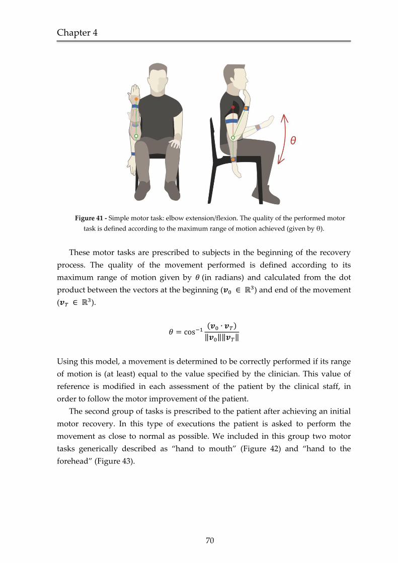
Chapter 4
70
Figure 41 - Simple motor task: elbow extension/flexion. The quality of the performed motor
task is defined according to the maximum range of motion achieved (given by θ).
These motor tasks are prescribed to subjects in the beginning of the recovery
process. The quality of the movement performed is defined according to its
maximum range of motion given by (in radians) and calculated from the dot
product between the vectors at the beginning ( ) and end of the movement
( ).
( )
‖ ‖‖ ‖
Using this model, a movement is determined to be correctly performed if its range
of motion is (at least) equal to the value specified by the clinician. This value of
reference is modified in each assessment of the patient by the clinical staff, in
order to follow the motor improvement of the patient.
The second group of tasks is prescribed to the patient after achieving an initial
motor recovery. In this type of executions the patient is asked to perform the
movement as close to normal as possible. We included in this group two motor
tasks generically described as “hand to mouth” (Figure 42) and “hand to the
forehead” (Figure 43).
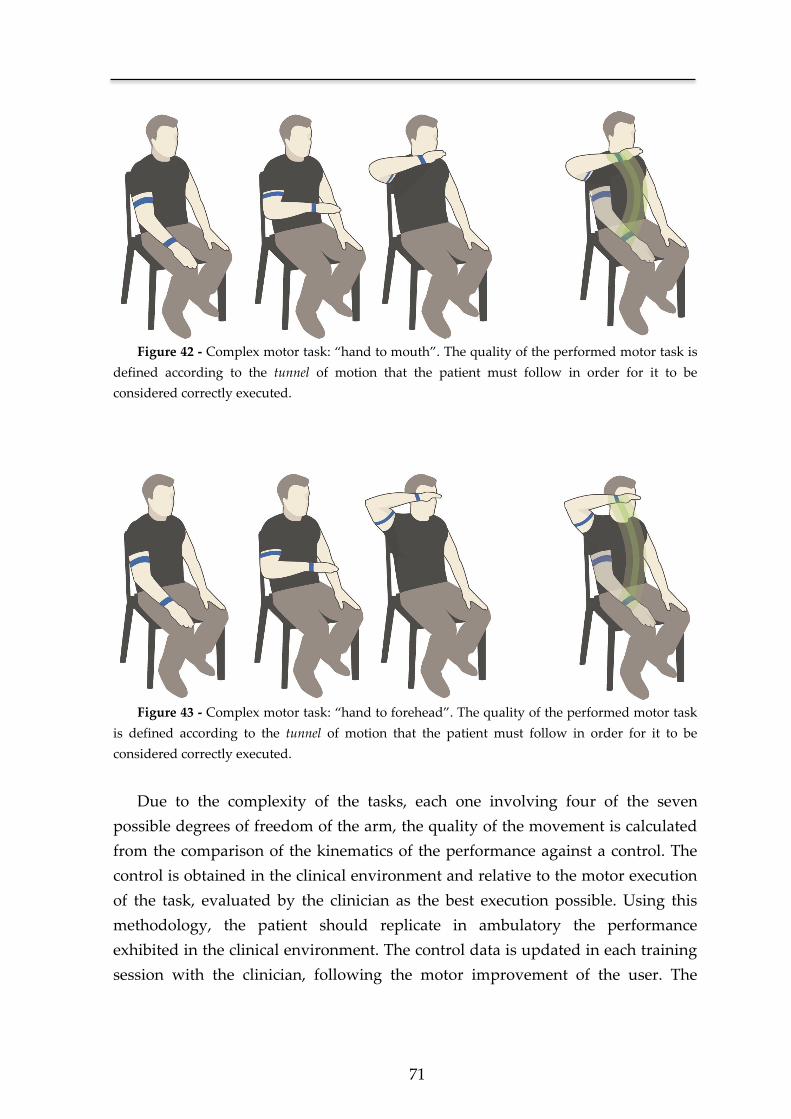
71
Figure 42 - Complex motor task: “hand to mouth”. The quality of the performed motor task is
defined according to the tunnel of motion that the patient must follow in order for it to be
considered correctly executed.
Figure 43 - Complex motor task: “hand to forehead”. The quality of the performed motor task
is defined according to the tunnel of motion that the patient must follow in order for it to be
considered correctly executed.
Due to the complexity of the tasks, each one involving four of the seven
possible degrees of freedom of the arm, the quality of the movement is calculated
from the comparison of the kinematics of the performance against a control. The
control is obtained in the clinical environment and relative to the motor execution
of the task, evaluated by the clinician as the best execution possible. Using this
methodology, the patient should replicate in ambulatory the performance
exhibited in the clinical environment. The control data is updated in each training
session with the clinician, following the motor improvement of the user. The
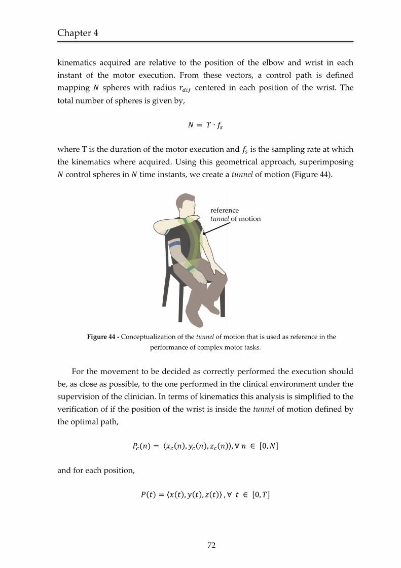
Chapter 4
72
kinematics acquired are relative to the position of the elbow and wrist in each
instant of the motor execution. From these vectors, a control path is defined
mapping spheres with radius centered in each position of the wrist. The
total number of spheres is given by,
where T is the duration of the motor execution and is the sampling rate at which
the kinematics where acquired. Using this geometrical approach, superimposing
control spheres in time instants, we create a tunnel of motion (Figure 44).
Figure 44 - Conceptualization of the tunnel of motion that is used as reference in the
performance of complex motor tasks.
For the movement to be decided as correctly performed the execution should
be, as close as possible, to the one performed in the clinical environment under the
supervision of the clinician. In terms of kinematics this analysis is simplified to the
verification of if the position of the wrist is inside the tunnel of motion defined by
the optimal path,
( ) ⟨ ( ) ( ) ( )⟩ [ ]
and for each position,
( ) ⟨ ( ) ( ) ( )⟩ [ ]
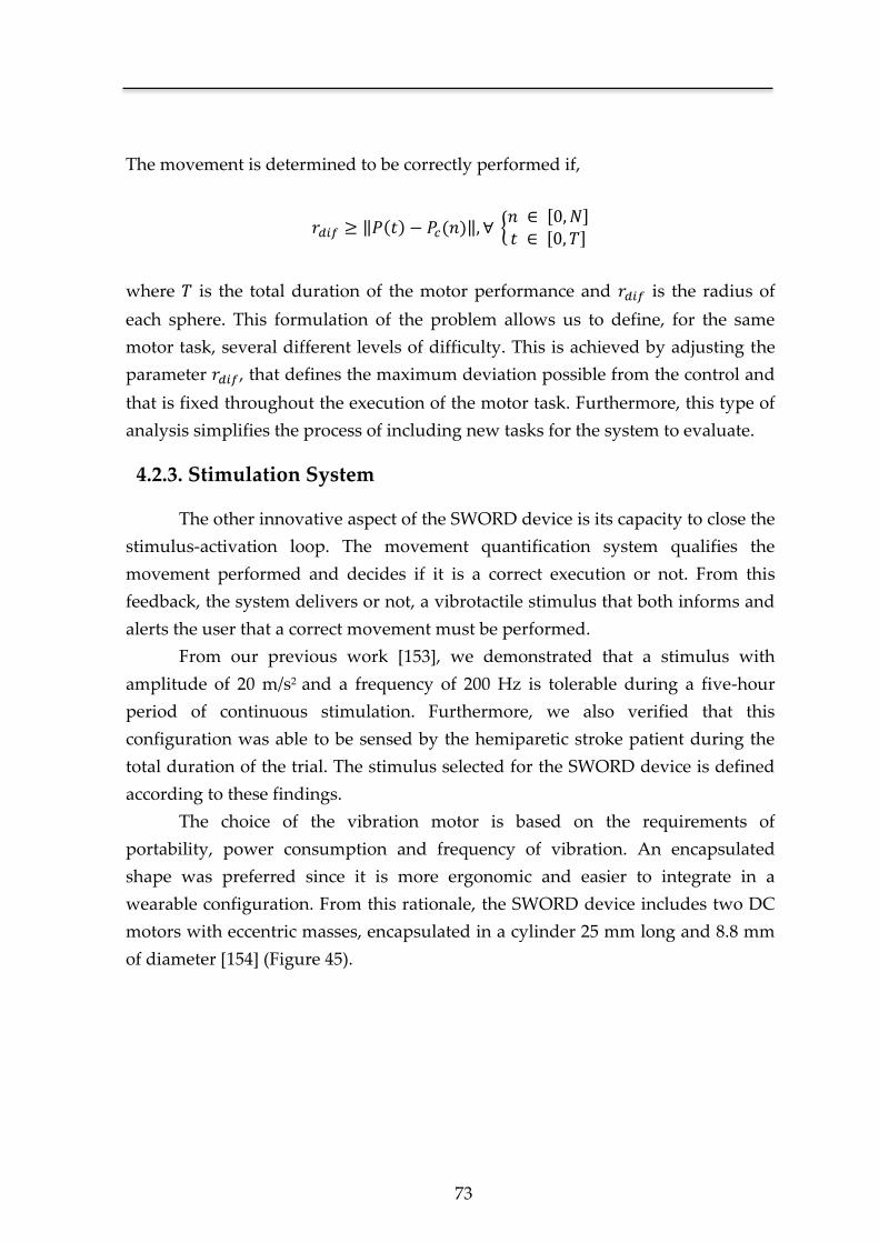
73
The movement is determined to be correctly performed if,
‖ ( ) ( )‖ { [ ]
[ ]
where is the total duration of the motor performance and is the radius of
each sphere. This formulation of the problem allows us to define, for the same
motor task, several different levels of difficulty. This is achieved by adjusting the
parameter , that defines the maximum deviation possible from the control and
that is fixed throughout the execution of the motor task. Furthermore, this type of
analysis simplifies the process of including new tasks for the system to evaluate.
4.2.3. Stimulation System
The other innovative aspect of the SWORD device is its capacity to close the
stimulus-activation loop. The movement quantification system qualifies the
movement performed and decides if it is a correct execution or not. From this
feedback, the system delivers or not, a vibrotactile stimulus that both informs and
alerts the user that a correct movement must be performed.
From our previous work [153], we demonstrated that a stimulus with
amplitude of 20 m/s2 and a frequency of 200 Hz is tolerable during a five-hour
period of continuous stimulation. Furthermore, we also verified that this
configuration was able to be sensed by the hemiparetic stroke patient during the
total duration of the trial. The stimulus selected for the SWORD device is defined
according to these findings.
The choice of the vibration motor is based on the requirements of
portability, power consumption and frequency of vibration. An encapsulated
shape was preferred since it is more ergonomic and easier to integrate in a
wearable configuration. From this rationale, the SWORD device includes two DC
motors with eccentric masses, encapsulated in a cylinder 25 mm long and 8.8 mm
of diameter [154] (Figure 45).
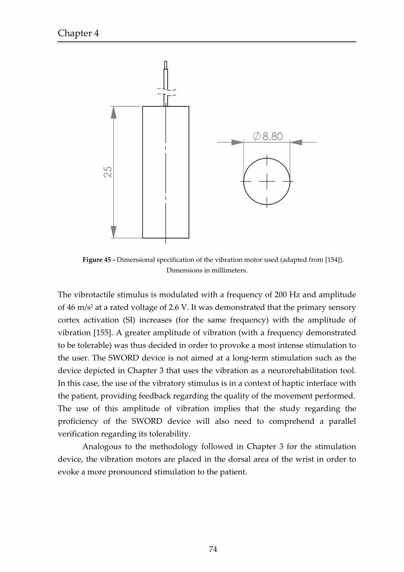
Chapter 4
74
Figure 45 - Dimensional specification of the vibration motor used (adapted from [154]).
Dimensions in millimeters.
The vibrotactile stimulus is modulated with a frequency of 200 Hz and amplitude
of 46 m/s2 at a rated voltage of 2.6 V. It was demonstrated that the primary sensory
cortex activation (SI) increases (for the same frequency) with the amplitude of
vibration [155]. A greater amplitude of vibration (with a frequency demonstrated
to be tolerable) was thus decided in order to provoke a most intense stimulation to
the user. The SWORD device is not aimed at a long-term stimulation such as the
device depicted in Chapter 3 that uses the vibration as a neurorehabilitation tool.
In this case, the use of the vibratory stimulus is in a context of haptic interface with
the patient, providing feedback regarding the quality of the movement performed.
The use of this amplitude of vibration implies that the study regarding the
proficiency of the SWORD device will also need to comprehend a parallel
verification regarding its tolerability.
Analogous to the methodology followed in Chapter 3 for the stimulation
device, the vibration motors are placed in the dorsal area of the wrist in order to
evoke a more pronounced stimulation to the patient.
75
4.2.4. System Architecture
The architecture of the SWORD device interconnects both features of
movement quantification and biofeedback given in the form of a vibratory
stimulus. The SWORD device is designed to be a complete neurorehabilitation tool
target at the motor recovery of both the upper and the lower-limbs.
In this Chapter we present the SWORD device specifically designed towards
the rehabilitation of the upper-limb. The model of Figure 46 represents the
architecture of the SWORD device that is capable of:
Acquire the three-dimensional kinematics of the upper-limb.
Perform a quality analysis of the motor task performed.
Provide a direct feedback to the patient in the form of a vibrotactile
stimulus.
Store the session data regarding the kinematics of the performed
movements, number and timing of correct/wrong executions.
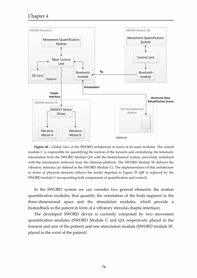
Chapter 4
76
Figure 46 - Global view of the SWORD architecture in terms of its main modules. The central
module C is responsible for quantifying the motion of the forearm and centralizing the kinematic
information from the SWORD Module QA with the biomechanical system, previously initialized
with the information retrieved from the clinician platform. The SWORD Module SF delivers the
vibratory stimulus (as defined in the SWORD Module C). The implementation of this architecture
in terms of physical elements follows the model depicted in Figure 35 (QF is replaced by the
SWORD module C incorporating both components of quantification and control).
In the SWORD system we can consider two general elements: the motion
quantification modules, that quantify the orientation of the body-segment in the
three-dimensional space and the stimulation modules, which provide a
biofeedback to the patient in form of a vibratory stimulus (haptic interface).
The developed SWORD device is currently composed by two movement
quantification modules (SWORD Module C and QA respectively placed in the
forearm and arm of the patient) and one stimulation module (SWORD module SF,
placed in the wrist of the patient).
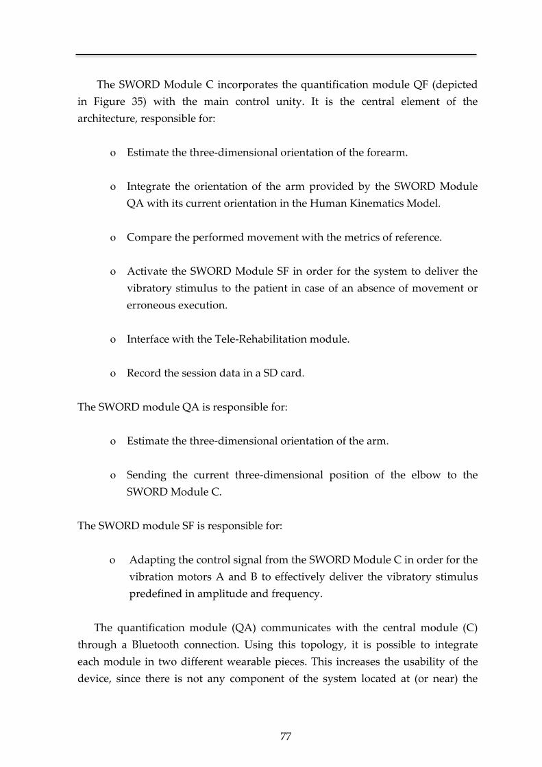
77
The SWORD Module C incorporates the quantification module QF (depicted
in Figure 35) with the main control unity. It is the central element of the
architecture, responsible for:
Estimate the three-dimensional orientation of the forearm.
Integrate the orientation of the arm provided by the SWORD Module
QA with its current orientation in the Human Kinematics Model.
Compare the performed movement with the metrics of reference.
Activate the SWORD Module SF in order for the system to deliver the
vibratory stimulus to the patient in case of an absence of movement or
erroneous execution.
Interface with the Tele-Rehabilitation module.
Record the session data in a SD card.
The SWORD module QA is responsible for:
Estimate the three-dimensional orientation of the arm.
Sending the current three-dimensional position of the elbow to the
SWORD Module C.
The SWORD module SF is responsible for:
Adapting the control signal from the SWORD Module C in order for the
vibration motors A and B to effectively deliver the vibratory stimulus
predefined in amplitude and frequency.
The quantification module (QA) communicates with the central module (C)
through a Bluetooth connection. Using this topology, it is possible to integrate
each module in two different wearable pieces. This increases the usability of the
device, since there is not any component of the system located at (or near) the
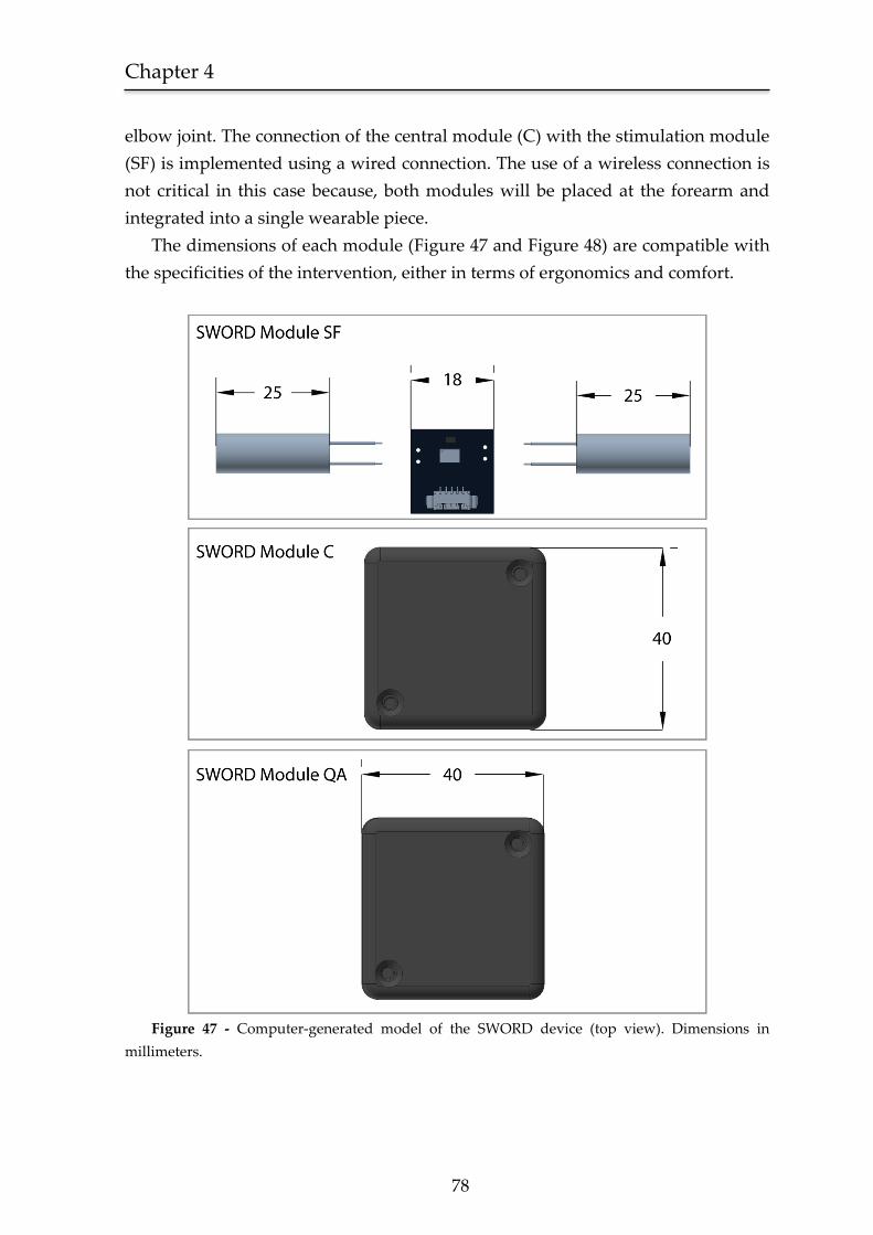
Chapter 4
78
elbow joint. The connection of the central module (C) with the stimulation module
(SF) is implemented using a wired connection. The use of a wireless connection is
not critical in this case because, both modules will be placed at the forearm and
integrated into a single wearable piece.
The dimensions of each module (Figure 47 and Figure 48) are compatible with
the specificities of the intervention, either in terms of ergonomics and comfort.
Figure 47 - Computer-generated model of the SWORD device (top view). Dimensions in
millimeters.
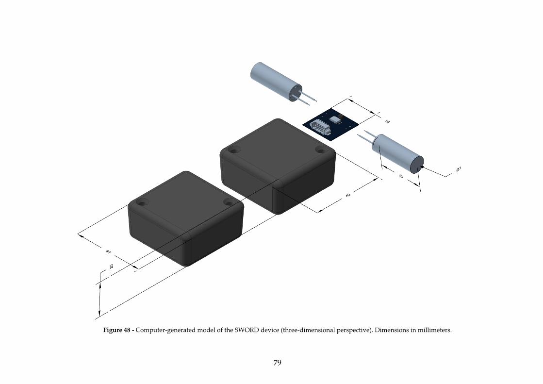
79
Figure 48 - Computer-generated model of the SWORD device (three-dimensional perspective). Dimensions in millimeters.
Chapter 4
80
Figure 49 - (a) In-house built motion quantification module, composed by a three-axis
gyroscope, a three-axis accelerometer and a three-axis magnetometer. The communication between
each module and its host is performed through a Bluetooth connection (b) Depiction of the
SWORD device in its wearable form, placed at the forearm and arm of a Stroke patient.
As referred in the description of the Human Kinematics Model, the SWORD
architecture (Figure 46) is easily scalable in order to incorporate the movement
dynamics of the shoulder segment. In order to achieve this, a third quantification
module should be included. This module (SWORD module QS, placed in the
shoulder segment of the patient) will interface with the central module, sending its
current orientation in order for the Human Kinematics Model to estimate the
position of the wrist, elbow and shoulder (Figure 50).
SWORD module QA
SWORD modules C and SF
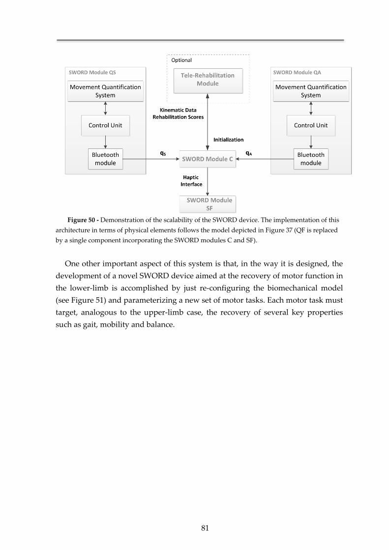
81
Figure 50 - Demonstration of the scalability of the SWORD device. The implementation of this
architecture in terms of physical elements follows the model depicted in Figure 37 (QF is replaced
by a single component incorporating the SWORD modules C and SF).
One other important aspect of this system is that, in the way it is designed, the
development of a novel SWORD device aimed at the recovery of motor function in
the lower-limb is accomplished by just re-configuring the biomechanical model
(see Figure 51) and parameterizing a new set of motor tasks. Each motor task must
target, analogous to the upper-limb case, the recovery of several key properties
such as gait, mobility and balance.
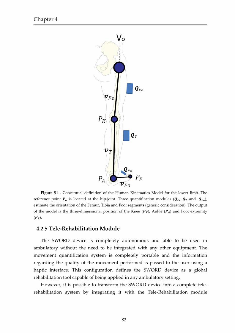
Chapter 4
82
Figure 51 - Conceptual definition of the Human Kinematics Model for the lower limb. The
reference point is located at the hip-joint. Three quantification modules ( , and ),
estimate the orientation of the Femur, Tibia and Foot segments (generic consideration). The output
of the model is the three-dimensional position of the Knee ( ), Ankle ( ) and Foot extremity
( ).
4.2.5 Tele-Rehabilitation Module
The SWORD device is completely autonomous and able to be used in
ambulatory without the need to be integrated with any other equipment. The
movement quantification system is completely portable and the information
regarding the quality of the movement performed is passed to the user using a
haptic interface. This configuration defines the SWORD device as a global
rehabilitation tool capable of being applied in any ambulatory setting.
However, it is possible to transform the SWORD device into a complete tele-
rehabilitation system by integrating it with the Tele-Rehabilitation module
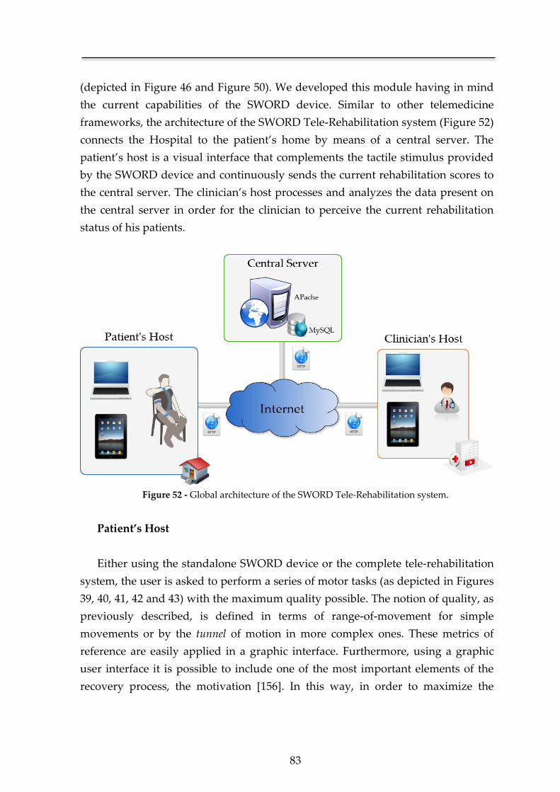
83
(depicted in Figure 46 and Figure 50). We developed this module having in mind
the current capabilities of the SWORD device. Similar to other telemedicine
frameworks, the architecture of the SWORD Tele-Rehabilitation system (Figure 52)
connects the Hospital to the patient’s home by means of a central server. The
patient’s host is a visual interface that complements the tactile stimulus provided
by the SWORD device and continuously sends the current rehabilitation scores to
the central server. The clinician’s host processes and analyzes the data present on
the central server in order for the clinician to perceive the current rehabilitation
status of his patients.
Figure 52 - Global architecture of the SWORD Tele-Rehabilitation system.
Patient’s Host
Either using the standalone SWORD device or the complete tele-rehabilitation
system, the user is asked to perform a series of motor tasks (as depicted in Figures
39, 40, 41, 42 and 43) with the maximum quality possible. The notion of quality, as
previously described, is defined in terms of range-of-movement for simple
movements or by the tunnel of motion in more complex ones. These metrics of
reference are easily applied in a graphic interface. Furthermore, using a graphic
user interface it is possible to include one of the most important elements of the
recovery process, the motivation [156]. In this way, in order to maximize the
Chapter 4
84
adherence of the user to the therapy, each interface incorporates a gaming
methodology.
Simple motor executions are trained using simple games (e.g Figure 53), that
correspond to the current range-of-movement performed by the patient (given by
θ) with the motion of a specific object on the screen. In the case of the Airplanes
game depicted in Figure 53, the patient controls the altitude of the plane by
flexing/extending the shoulder (motor task depicted in Figure 41). The patient
must try to avoid the objects that will appear on the screen. The difficulty of the
game is set by the speed of the plane, the faster the airplane moves, the quicker the
patient has to control his arm.
The training of complex motor executions is performed using a different
interface and methodology. As previously referred, the quality of a complex motor
task is determined according to its trajectory. In this case the conceptual model of
the tunnel of motion is no longer transparent, being transformed in a graphic cue
for the patient (see Figure 54). The avatar on the screen mimics the movement of
the patient, and in order for a motor task to be correctly executed its wrist must be
always inside the tunnel of motion. The notion of difficulty in this case is set by
how narrow the tunnel is. A narrower tunnel will imply that in order for the task
to be successfully executed, its deviation from the reference kinematics must be
minimal.
In each one the two interfaces of training (for simple and complex motor
executions), the console is continuously sending to the central server, data
regarding the number of correct/wrong executions, performance timing and
current level of difficulty. The airplanes game (Figure 53) was developed using the
cross-platform engine Adobe AIR® and integrated into the global framework
developed in Python®. The graphic interface of Figure 54 was developed using the
VPython® module. Using this tool we optimize the proficiency of the intervention
by combining both components of haptic and visual interfaces. Additionally, by
continuously sending the current rehabilitation scores, the recovery of the patient
is precisely documented providing a valuable insight to the clinical staff and
enabling a more efficient management of the rehabilitation plan.
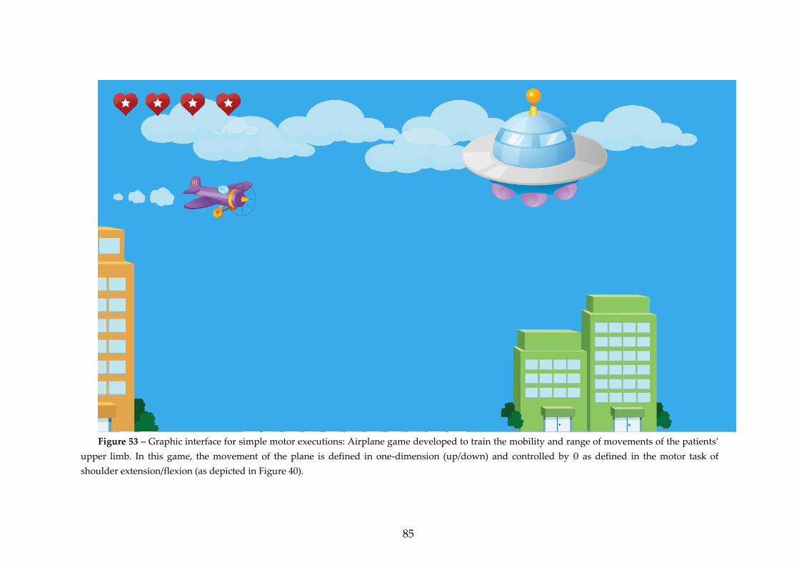
85
Figure 53 – Graphic interface for simple motor executions: Airplane game developed to train the mobility and range of movements of the patients’
upper limb. In this game, the movement of the plane is defined in one-dimension (up/down) and controlled by θ as defined in the motor task of
shoulder extension/flexion (as depicted in Figure 40).
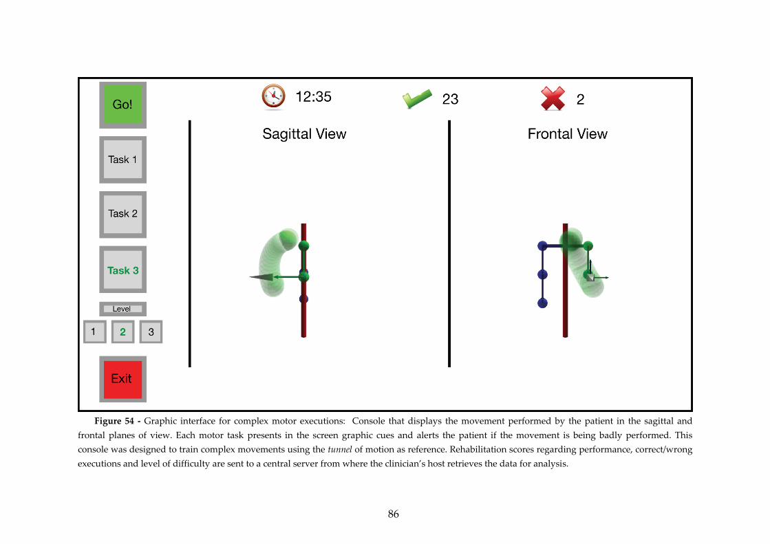
86
Figure 54 - Graphic interface for complex motor executions: Console that displays the movement performed by the patient in the sagittal and
frontal planes of view. Each motor task presents in the screen graphic cues and alerts the patient if the movement is being badly performed. This
console was designed to train complex movements using the tunnel of motion as reference. Rehabilitation scores regarding performance, correct/wrong
executions and level of difficulty are sent to a central server from where the clinician’s host retrieves the data for analysis.
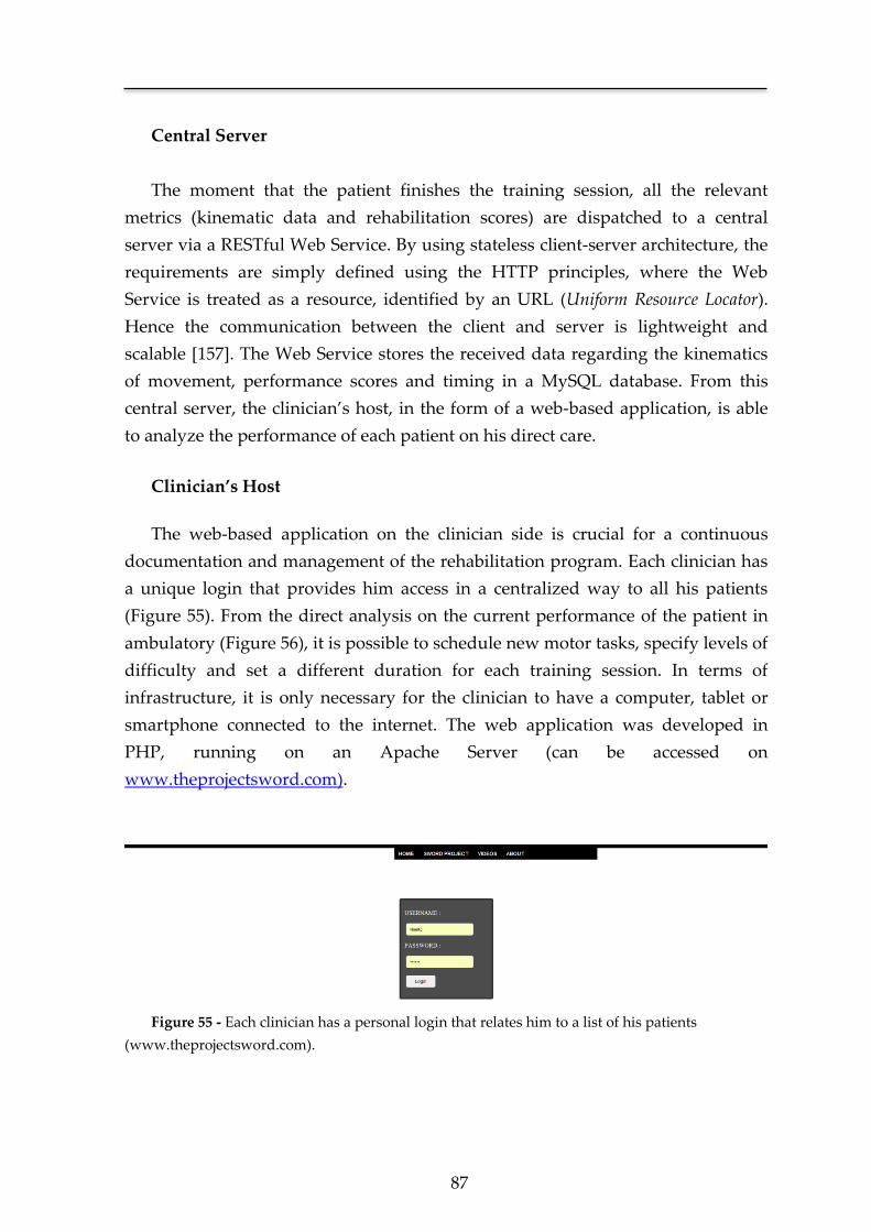
87
Central Server
The moment that the patient finishes the training session, all the relevant
metrics (kinematic data and rehabilitation scores) are dispatched to a central
server via a RESTful Web Service. By using stateless client-server architecture, the
requirements are simply defined using the HTTP principles, where the Web
Service is treated as a resource, identified by an URL (Uniform Resource Locator).
Hence the communication between the client and server is lightweight and
scalable [157]. The Web Service stores the received data regarding the kinematics
of movement, performance scores and timing in a MySQL database. From this
central server, the clinician’s host, in the form of a web-based application, is able
to analyze the performance of each patient on his direct care.
Clinician’s Host
The web-based application on the clinician side is crucial for a continuous
documentation and management of the rehabilitation program. Each clinician has
a unique login that provides him access in a centralized way to all his patients
(Figure 55). From the direct analysis on the current performance of the patient in
ambulatory (Figure 56), it is possible to schedule new motor tasks, specify levels of
difficulty and set a different duration for each training session. In terms of
infrastructure, it is only necessary for the clinician to have a computer, tablet or
smartphone connected to the internet. The web application was developed in
PHP, running on an Apache Server (can be accessed on
www.theprojectsword.com).
Figure 55 - Each clinician has a personal login that relates him to a list of his patients
(www.theprojectsword.com).
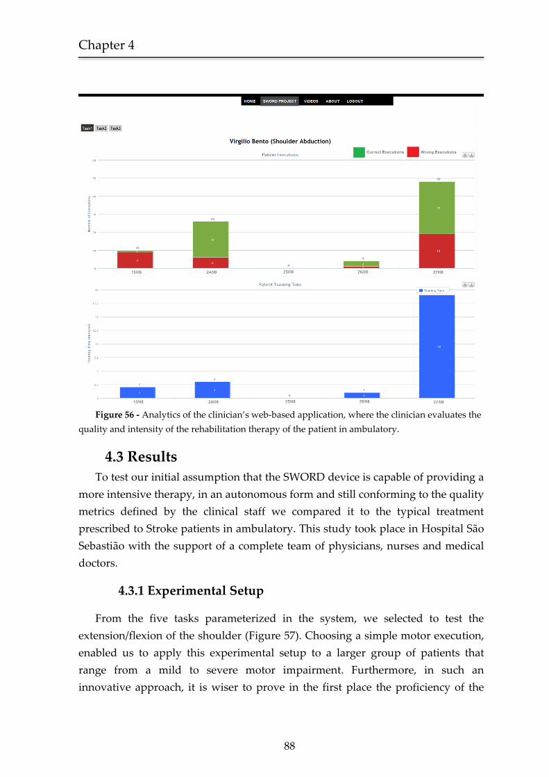
Chapter 4
88
Figure 56 - Analytics of the clinician’s web-based application, where the clinician evaluates the
quality and intensity of the rehabilitation therapy of the patient in ambulatory.
4.3 Results
To test our initial assumption that the SWORD device is capable of providing a
more intensive therapy, in an autonomous form and still conforming to the quality
metrics defined by the clinical staff we compared it to the typical treatment
prescribed to Stroke patients in ambulatory. This study took place in Hospital São
Sebastião with the support of a complete team of physicians, nurses and medical
doctors.
4.3.1 Experimental Setup
From the five tasks parameterized in the system, we selected to test the
extension/flexion of the shoulder (Figure 57). Choosing a simple motor execution,
enabled us to apply this experimental setup to a larger group of patients that
range from a mild to severe motor impairment. Furthermore, in such an
innovative approach, it is wiser to prove in the first place the proficiency of the
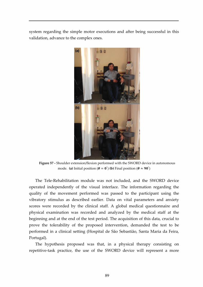
89
system regarding the simple motor executions and after being successful in this
validation, advance to the complex ones.
Figure 57 - Shoulder extension/flexion performed with the SWORD device in autonomous
mode. (a) Initial position ( ) (b) Final position ( )
The Tele-Rehabilitation module was not included, and the SWORD device
operated independently of the visual interface. The information regarding the
quality of the movement performed was passed to the participant using the
vibratory stimulus as described earlier. Data on vital parameters and anxiety
scores were recorded by the clinical staff. A global medical questionnaire and
physical examination was recorded and analyzed by the medical staff at the
beginning and at the end of the test period. The acquisition of this data, crucial to
prove the tolerability of the proposed intervention, demanded the test to be
performed in a clinical setting (Hospital de São Sebastião, Santa Maria da Feira,
Portugal).
The hypothesis proposed was that, in a physical therapy consisting on
repetitive-task practice, the use of the SWORD device will represent a more
Chapter 4
90
intensive training when compared against the scenario where the patient is asked
to repeatedly perform the task and no further information is given relative to the
quality of his current performance (typical ambulatory setting). To infer this
hypothesis, we tested two different interventions:
(a) Typical Treatment - Repetitive-task practice of the shoulder
extension/flexion using the movement quantification system of the SWORD
device.
(b) SWORD Treatment - Repetitive-task practice of the shoulder
extension/flexion using the SWORD device (with both components of haptic
interface, movement quantification and quality control).
The inclusion of the movement quantification system in both interventions was
necessary in order to quantify in the same form the patient’s maximum range of
motion. As depicted earlier, this is the metric that will be used as reference in the
determination of a movement’s quality. In this way, in both cases, the movement
will be determined to be correctly performed if its range of motion is (at least)
equal to the value defined by the clinician in the initial assessment of the patient,
performed in the beginning of the trial.
The study compared the two treatments in a cross-over design performed in two
consecutive days as following,
In day 1, the patient was assigned to treatment (a) and performed it
during minutes. After conclusion, the patient rested 15 minutes
and then he was assigned to treatment (b), performing it also during
minutes.
In day 2, the sequence of training changed and the patient was first
assigned to treatment (b) and performed it during minutes. After
conclusion, the patient rested 15 minutes and then he was assigned
to treatment (a) performing it also during minutes.
With this methodology, our aim was to cancel the influence that the patient’s
fatigue after the first treatment could have on his performance on the second
treatment. The duration of the treatment ( ) and maximum possible delay
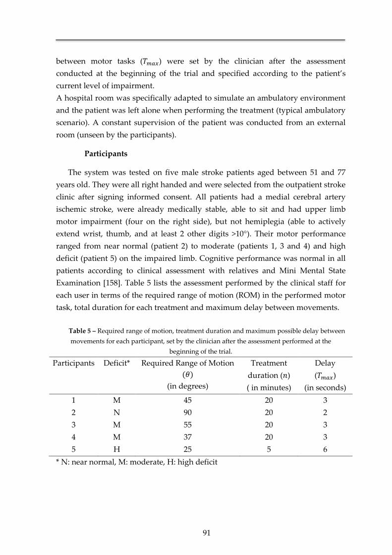
91
between motor tasks ( ) were set by the clinician after the assessment
conducted at the beginning of the trial and specified according to the patient’s
current level of impairment.
A hospital room was specifically adapted to simulate an ambulatory environment
and the patient was left alone when performing the treatment (typical ambulatory
scenario). A constant supervision of the patient was conducted from an external
room (unseen by the participants).
Participants
The system was tested on five male stroke patients aged between 51 and 77
years old. They were all right handed and were selected from the outpatient stroke
clinic after signing informed consent. All patients had a medial cerebral artery
ischemic stroke, were already medically stable, able to sit and had upper limb
motor impairment (four on the right side), but not hemiplegia (able to actively
extend wrist, thumb, and at least 2 other digits >10°). Their motor performance
ranged from near normal (patient 2) to moderate (patients 1, 3 and 4) and high
deficit (patient 5) on the impaired limb. Cognitive performance was normal in all
patients according to clinical assessment with relatives and Mini Mental State
Examination [158]. Table 5 lists the assessment performed by the clinical staff for
each user in terms of the required range of motion (ROM) in the performed motor
task, total duration for each treatment and maximum delay between movements.
Table 5 – Required range of motion, treatment duration and maximum possible delay between
movements for each participant, set by the clinician after the assessment performed at the
beginning of the trial.
Participants Deficit* Required Range of Motion
( )
(in degrees)
Treatment
duration ( )
( in minutes)
Delay
( )
(in seconds)
1 M 45 20 3
2 N 90 20 2
3 M 55 20 3
4 M 37 20 3
5 H 25 5 6
* N: near normal, M: moderate, H: high deficit
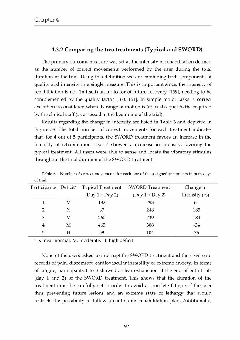
Chapter 4
92
4.3.2 Comparing the two treatments (Typical and SWORD)
The primary outcome measure was set as the intensity of rehabilitation defined
as the number of correct movements performed by the user during the total
duration of the trial. Using this definition we are combining both components of
quality and intensity in a single measure. This is important since, the intensity of
rehabilitation is not (in itself) an indicator of future recovery [159], needing to be
complemented by the quality factor [160, 161]. In simple motor tasks, a correct
execution is considered when its range of motion is (at least) equal to the required
by the clinical staff (as assessed in the beginning of the trial).
Results regarding the change in intensity are listed in Table 6 and depicted in
Figure 58. The total number of correct movements for each treatment indicates
that, for 4 out of 5 participants, the SWORD treatment favors an increase in the
intensity of rehabilitation. User 4 showed a decrease in intensity, favoring the
typical treatment. All users were able to sense and locate the vibratory stimulus
throughout the total duration of the SWORD treatment.
Table 6 – Number of correct movements for each one of the assigned treatments in both days
of trial.
Participants Deficit* Typical Treatment
(Day 1 + Day 2)
SWORD Treatment
(Day 1 + Day 2)
Change in
intensity (%)
1 M 182 293 61
2 N 87 248 185
3 M 260 739 184
4 M 465 308 -34
5 H 59 104 76
* N: near normal, M: moderate, H: high deficit
None of the users asked to interrupt the SWORD treatment and there were no
records of pain, discomfort, cardiovascular instability or extreme anxiety. In terms
of fatigue, participants 1 to 3 showed a clear exhaustion at the end of both trials
(day 1 and 2) of the SWORD treatment. This shows that the duration of the
treatment must be carefully set in order to avoid a complete fatigue of the user
thus preventing future lesions and an extreme state of lethargy that would
restricts the possibility to follow a continuous rehabilitation plan. Additionally,
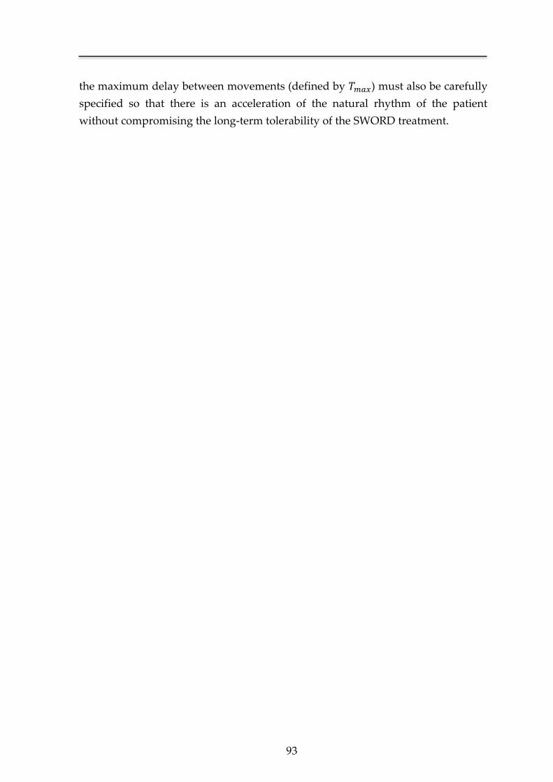
93
the maximum delay between movements (defined by ) must also be carefully
specified so that there is an acceleration of the natural rhythm of the patient
without compromising the long-term tolerability of the SWORD treatment.
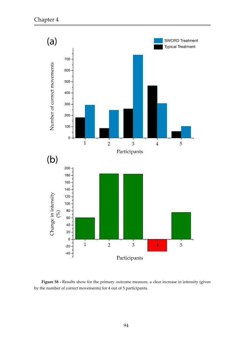
Chapter 4
94
Figure 58 - Results show for the primary outcome measure, a clear increase in intensity (given
by the number of correct movements) for 4 out of 5 participants.
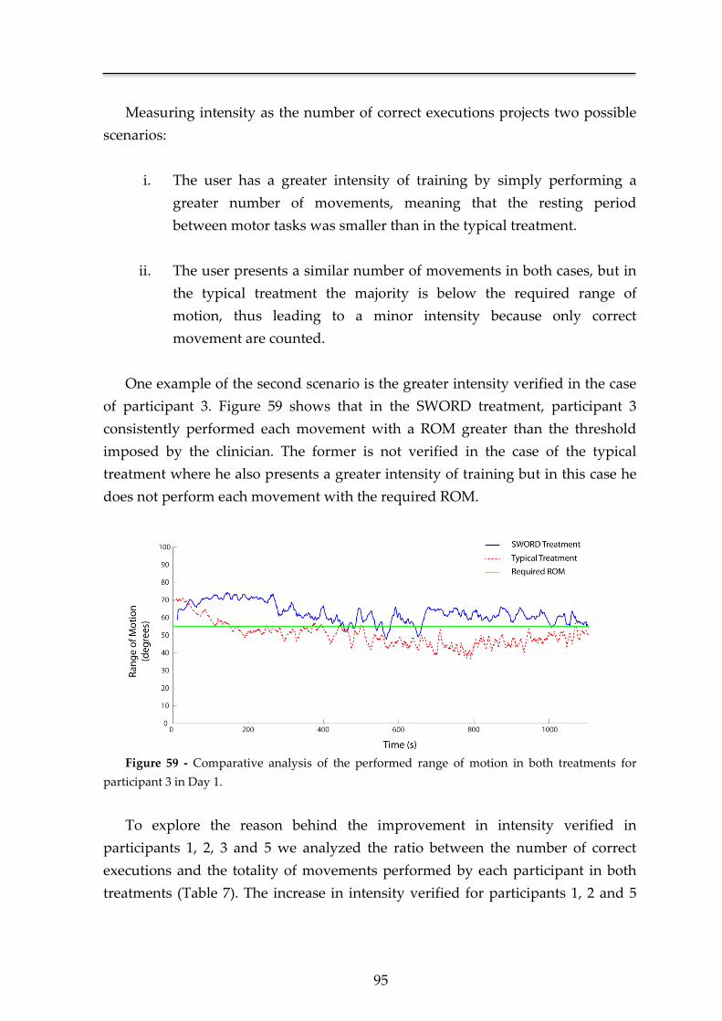
95
Measuring intensity as the number of correct executions projects two possible
scenarios:
i. The user has a greater intensity of training by simply performing a
greater number of movements, meaning that the resting period
between motor tasks was smaller than in the typical treatment.
ii. The user presents a similar number of movements in both cases, but in
the typical treatment the majority is below the required range of
motion, thus leading to a minor intensity because only correct
movement are counted.
One example of the second scenario is the greater intensity verified in the case
of participant 3. Figure 59 shows that in the SWORD treatment, participant 3
consistently performed each movement with a ROM greater than the threshold
imposed by the clinician. The former is not verified in the case of the typical
treatment where he also presents a greater intensity of training but in this case he
does not perform each movement with the required ROM.
Figure 59 - Comparative analysis of the performed range of motion in both treatments for
participant 3 in Day 1.
To explore the reason behind the improvement in intensity verified in
participants 1, 2, 3 and 5 we analyzed the ratio between the number of correct
executions and the totality of movements performed by each participant in both
treatments (Table 7). The increase in intensity verified for participants 1, 2 and 5
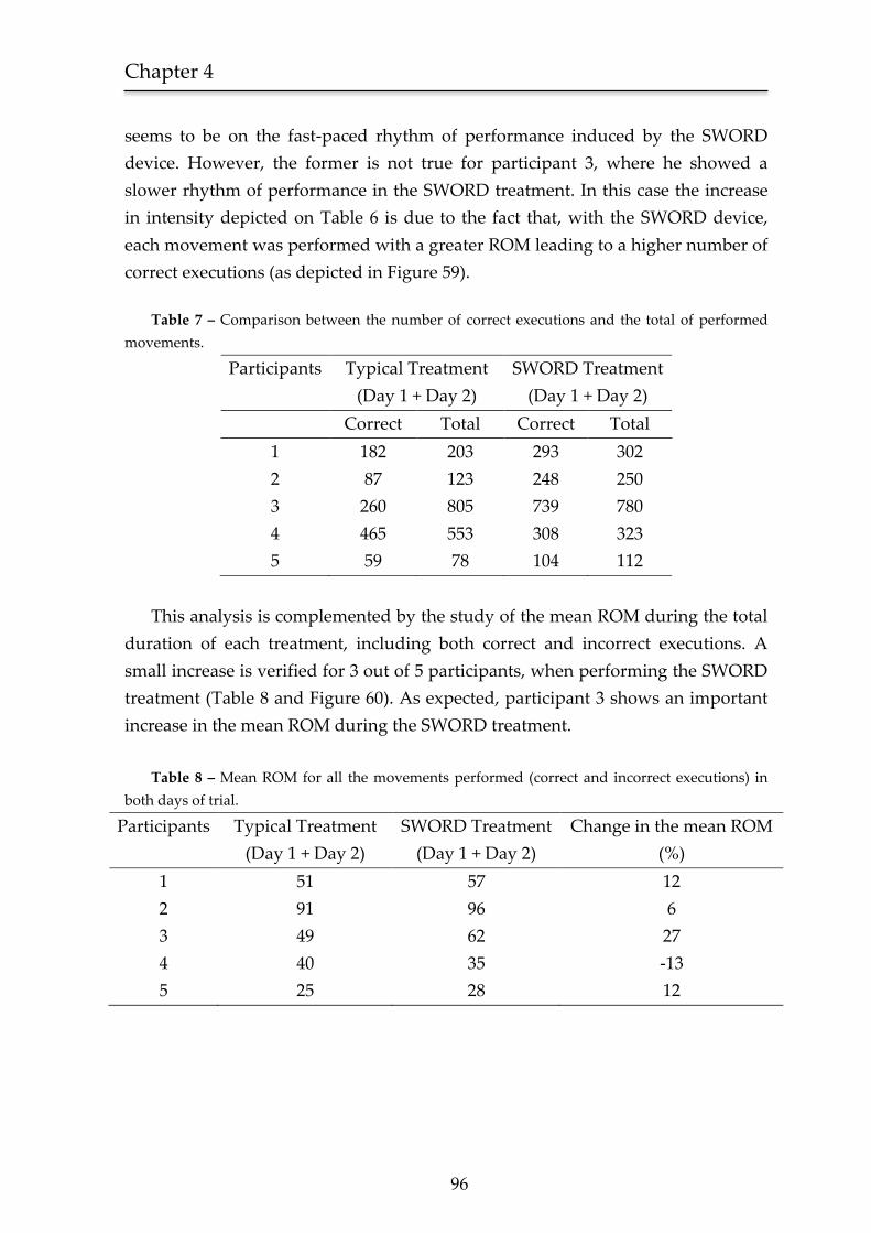
Chapter 4
96
seems to be on the fast-paced rhythm of performance induced by the SWORD
device. However, the former is not true for participant 3, where he showed a
slower rhythm of performance in the SWORD treatment. In this case the increase
in intensity depicted on Table 6 is due to the fact that, with the SWORD device,
each movement was performed with a greater ROM leading to a higher number of
correct executions (as depicted in Figure 59).
Table 7 – Comparison between the number of correct executions and the total of performed
movements.
Participants Typical Treatment
(Day 1 + Day 2)
SWORD Treatment
(Day 1 + Day 2)
Correct Total Correct Total
1 182 203 293 302
2 87 123 248 250
3 260 805 739 780
4 465 553 308 323
5 59 78 104 112
This analysis is complemented by the study of the mean ROM during the total
duration of each treatment, including both correct and incorrect executions. A
small increase is verified for 3 out of 5 participants, when performing the SWORD
treatment (Table 8 and Figure 60). As expected, participant 3 shows an important
increase in the mean ROM during the SWORD treatment.
Table 8 – Mean ROM for all the movements performed (correct and incorrect executions) in
both days of trial.
Participants Typical Treatment
(Day 1 + Day 2)
SWORD Treatment
(Day 1 + Day 2)
Change in the mean ROM
(%)
1 51 57 12
2 91 96 6
3 49 62 27
4 40 35 -13
5 25 28 12
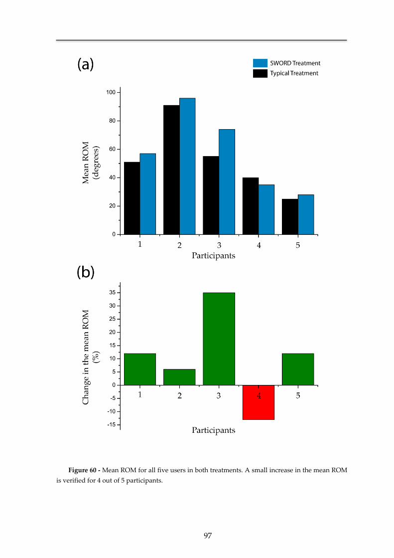
97
Figure 60 - Mean ROM for all five users in both treatments. A small increase in the mean ROM
is verified for 4 out of 5 participants.
Chapter 4
98
These findings suggest that the intervention of the SWORD device not only
sets the rhythm of training but also forces on the participant a correct performance
throughout the total duration of the session. Each of these scenarios plays a
different role depending on the participant’s typology. In motivated participants
(participant 3) the proficiency provided in the SWORD treatment seems to derive
from a higher quality of execution. Participants with a slower rhythm of
performance (participants 1, 2 and 5) have a greater intensity of training during
the SWORD treatment due to the fast-paced execution induced by the SWORD
device (also complemented by a small increase in the mean ROM). A precise
analysis on the reason behind the worst performance verified in the case of
participant 4 is not possible due to the small sample size of this study. This data
must be complemented with a larger clinical trial, where a correlation between
several specific neurological deficits (e.g. visual neglect [162]) and the performance
of a participant in both treatments is made possible. We can speculate that the
reason behind the performance verified for participant 3 was a failure to
understand the instructions of the therapy.
4.4 Discussion
In this Chapter we present the development of a novel rehabilitation device
designed to be used in ambulatory, combining both features of quality control and
intervention. Specified to be used in an autonomous mode, the structure of the
SWORD device permits a wide range of different applications. By integrating it
with the tele-rehabilitation module, we obtain a novel system that complements
the haptic with a visual interface, capable of continuously documenting the
recovery of the patient in ambulatory. Furthermore, it is easily prototyped to be
used as a rehabilitation tool for the lower-limb (following the same conceptual
approach).
Compared with other state-of-art technology-based interventions in Stroke
rehabilitation [123, 132, 133], the SWORD device has several competitive
advantages. Its wearable structure is light-weight, ergonomic and low-cost. Being
easily configured to include new simple and complex motor tasks, it is suited to be
applied in all stages of motor recovery of the patient. Furthermore, as
demonstrated in Chapter 3, the followed methodology based on a haptic interface
is safe and tolerable by the patient, promoting its intensive use in ambulatory.
These advantages derive from the paradigm-shattering approach pursued, that
99
creates a new segment in terms of technology-based interventions in Stroke
rehabilitation.
The experimental study was designed to assess the effectiveness of the
SWORD device in 5 participants. Results show that, for 4 in 5 participants, the use
of the SWORD device promoted a clear increase in the intensity of training.
Lacking the statistical evidence of a larger clinical trial, this data is essential to
observe in practice the interaction between the SWORD device and the patient.
The increase in intensity, defined as the number of correct executions performed
during the totality of the trial, confirms our initial assumptions that the
intervention of the haptic interface is capable of promoting a higher rhythm and
quality on motor execution.
4.5 Conclusion
This study confirms the SWORD device as a rehabilitation tool capable of
providing an intervention focused on intensive repetitive task-specific practice
with feedback on performance, the three golden rules for a successful restoration
of motor function after a Stroke [21].
One other important fact retrieved from this study is the need for a correct
management of the intensity promoted by the SWORD device, in order to prevent
extreme states of fatigue. The initial configuration of the intervention, defining the
required ROM, maximum delay between motor tasks and total duration of the
trial must follow a methodology that aggregates the patient’s current status of
motor/cognitive impairment, cardiovascular stress and aerobic performance [163].
The promising nature of these results must be complemented with a larger
clinical trial designed to assess the proficiency of the SWORD device when used in
ambulatory during the first three months after a Stroke. Parallel to this clinical
trial, a second one should be performed, following the same methodology, but in
this case, testing only complex motor executions. There are several other research
lines to explore in order to optimize the proficiency of the SWORD device, such as
the relation between the configuration of the SWORD treatment, motor
impairment of the patient at baseline and respective aerobic performance.
Additionally, the evolution of the SWORD device is highly-dependent on the
inclusion of other motor tasks, that must be subject of testing before being
parameterized into the system.
An unequivocally demonstration of the SWORD device as an effective
rehabilitation tool validates the research line created and potentiates the

Chapter 4
100
development of several tools that descend from the main structure (e.g. the
SWORD tele-rehabilitation system).

Chapter 5 A movement quantification system capable of
automatic evaluation of upper limb motor function
*Adapted from an original publication:
Bento V. F., Cruz V. T., Ribeiro D. D., Cunha J. P. S
Student Paper Competition Finalist (Top 2% of applicants).
Annual International Conference of the IEEE, Engineering in Medicine
and Biology Society (EMBC), Boston, USA, 2011.

Chapter 5
102
The need for a precise and accurate evaluation of motor improvement during
the early post-stroke phase demands reliable and valid tools. In this context, the
development of a system capable of an automatic assessment of motor function is
of increased importance since it would allow clinicians to document in a non-bias
and continuous form the improvement of motor function in patients.
A portable motion capture system was developed in order to obtain all the
relevant three-dimensional kinematics of upper limb movements. These
kinematics were analyzed by means of a decision tree classifier whose features
were inferred from the Functional Ability Score (FAS) of the Wolf Motor Function
Test (WMFT). In addition, the system was able to measure the performance time
of each selected task of the WMFT.
In relation to the FAS evaluation, the system and the clinician showed coherent
results in 4 out of 5 users for both motor tasks evaluated. Regarding performance
time, the mean difference between the system and the clinician was 0.17 s for the
25 trials performed (5 users, 5 tasks each).
These results represent an important proof of concept towards a system
capable of precisely evaluate upper limb motor function after neurological injury
and, consequently, support a more efficient management of the rehabilitation
plan. The underlying motion capture system was designed to be totally portable
and low-cost, being easily assembled in a wearable garment. Therefore, it is suited
to be integrated in an ambulatory framework allowing clinicians to continuously
document the recovery process and, should it be necessary, to remotely adjust the
rehabilitation plan or specific medication.
103
5.1 Introduction
When clinicians attempt to measure motor improvement during the early
post-stroke phase, reliable and accurate tools are needed. Currently, the
assessment of motor function is performed by a clinician in accordance with the
protocol and guidelines of a specific rating scale. This methodology, as stated by
Hobart et al [164], entails two important limitations. First, the score that represents
the level of motor function of the patient is referenced to an ordinal scale, which
leads to an inherent lack of precision. Secondly, since the score is a direct result of
the clinician’s interpretation of the guidelines, there is a lack of objectivity being
unknown which variable were quantified in the evaluation.
Therefore, the underlying nature of rating scales is in clear contrast with the
scientific rigor essential in clinical procedures. This fact assumes an increased
importance, since rating scales are the core of clinical trials and the absolute metric
in the decision regarding the effectiveness of the proposed treatment [164]. Also,
in patient care, continuous monitoring of motor status would represent a
significant upgrade in the management of future rehabilitation plans, indicating
that there isn’t room for a trade-off between accuracy and time consumption. The
scarcity of specialized human resources in a clinical environment limits the
number of possible motor tests performed by a patient, restricting a correct
assessment of performance during recovery. These facts combined, highlight the
need for a new framework able to provide an evaluation of motor function in an
accurate, rigorous and, more importantly, reproducible form.
In this context, the development of a system capable of an automatic
assessment of motor function is of increased importance since it would allow
clinicians to continuously document motor recovery and dynamically adjust the
rehabilitation schedule. The mechanics behind the evaluation would rely on a set
of metrics and not on a generic guideline. Another important aspect is the higher
accuracy that a motion capture system, in theory, could offer by removing the
human subjectivity from the analysis and allowing the quantification of specific
movements performed in all three dimensions.
Although being a rather new area of research, some diversified approaches
have been suggested. Patel et al. [143] proposed the use of accelerometers in
combination with a Random Forest classifier. From the accelerometer data, several
parameters could be extracted, such as the mean value of the accelerometer time
series. However, this approach demands that each subject performs, for each task,
Chapter 5
104
5 to 20 repetitions. Other studies [165, 166] propose the use of a video tracking
system to acquire the kinematics of the movement performed for each task. This
type of solution, based on the use of a set of video cameras, is efficient in terms of
motion capture. As a downside, this technology incorporates high costs of
production. Moreover the system is easily affected by occlusions being best suited
for a clean environment without movements on the background.
The aim of this study is to present the development and feasibility of a
system capable of evaluating, in an automatic manner, the motor function of a
patient in a precise and rapid form, suitable for easy implementation in an
ordinary clinical environment, with all its inherent constraints.
5.2 Methods
5.2.1 WMFT Description
The first step in the development of a system capable of automatic
assessment of upper limb motor function is the design of a set of rules derived
from the knowledge provided by the traditional direct-observation performance
tests, which have been increasingly perfected through empirical learning.
Several different tests, with different approaches, have been developed
with the same goal. The most reviewed tests in literature are the Action Research
Arm Test (ARAT) [167, 168], the Fugl-Meyer Assessment (FMA) of Physical
Performance [169, 170] and the Wolf Motor Function Test (WMFT) [171, 172].
From these, the WMFT was selected as the system’s reference in terms of upper
limb motor function evaluation. The WMFT is a valuable tool in this respect being
composed by a set of tasks arranged in order of complexity, from proximal to
distal joint assessment, combined into a global upper limb movement evaluation
[171, 173]. Additionally, a substantial amount of data is available regarding
concepts such as minimal detectable change and clinically important differences in
stroke patients [174, 175]. When compared with other motor assessment scales (e.g.
the FMA test) the WMFT is less time consuming, easier to use and provides
information that can orient contemporary functional rehabilitation strategies.
Furthermore, when we consider the evaluation of stroke patients or other
unilateral brain injury models, WMFT scores are able to depict changes on the
most affected side as well as on the less affected limb [176].
105
The complete testing protocol of the WMFT contains a total of 17 tasks. From
these, 15 tasks are used to evaluate the performance time (measured in seconds)
and functional ability score (FAS), measured according to an ordinal scale of 0-5.
In terms of motor function, each task evaluates a specific property of the execution
such as the range of movement, gross motor skills or dexterity.
In order to preliminary validate the hypothesis that a system is capable of
automatically evaluate motor function and performance time with, at least, the
same proficiency of an experimented clinician, a subset of 5 tasks were selected
from the 15 possible. The rationale behind this option is in the assumption that
such a complex challenge must be first validated for a specific type of motor
executions. Consequently, the 5 selected tasks to be integrated into the system,
target the evaluation of the motor gross skills of the patient’s upper limb. A
description of these tasks is given in Table 9 and complemented in Figure 61.
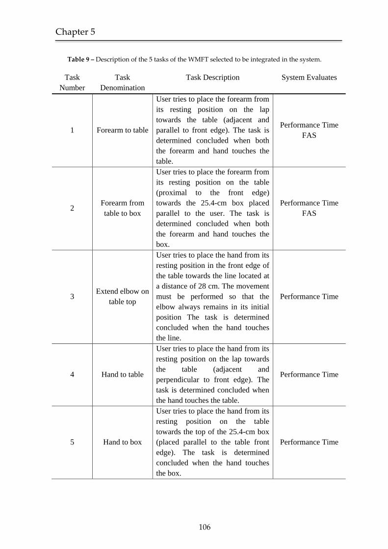
Chapter 5
106
Table 9 – Description of the 5 tasks of the WMFT selected to be integrated in the system.
Task
Number
Task
Denomination
Task Description System Evaluates
1 Forearm to table
User tries to place the forearm from
its resting position on the lap
towards the table (adjacent and
parallel to front edge). The task is
determined concluded when both
the forearm and hand touches the
table.
Performance Time
FAS
2 Forearm from
table to box
User tries to place the forearm from
its resting position on the table
(proximal to the front edge)
towards the 25.4-cm box placed
parallel to the user. The task is
determined concluded when both
the forearm and hand touches the
box.
Performance Time
FAS
3 Extend elbow on
table top
User tries to place the hand from its
resting position in the front edge of
the table towards the line located at
a distance of 28 cm. The movement
must be performed so that the
elbow always remains in its initial
position The task is determined
concluded when the hand touches
the line.
Performance Time
4 Hand to table
User tries to place the hand from its
resting position on the lap towards
the table (adjacent and
perpendicular to front edge). The
task is determined concluded when
the hand touches the table.
Performance Time
5 Hand to box
User tries to place the hand from its
resting position on the table
towards the top of the 25.4-cm box
(placed parallel to the table front
edge). The task is determined
concluded when the hand touches
the box.
Performance Time
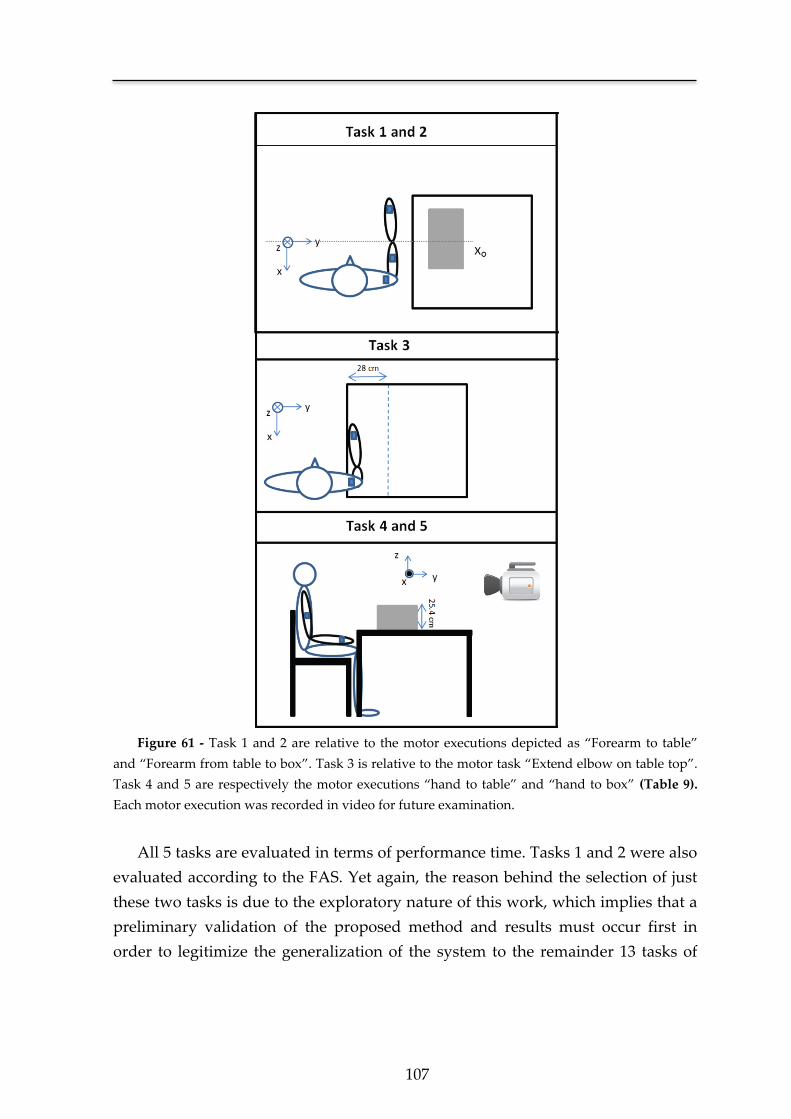
107
Figure 61 - Task 1 and 2 are relative to the motor executions depicted as “Forearm to table”
and “Forearm from table to box”. Task 3 is relative to the motor task “Extend elbow on table top”.
Task 4 and 5 are respectively the motor executions “hand to table” and “hand to box” (Table 9).
Each motor execution was recorded in video for future examination.
All 5 tasks are evaluated in terms of performance time. Tasks 1 and 2 were also
evaluated according to the FAS. Yet again, the reason behind the selection of just
these two tasks is due to the exploratory nature of this work, which implies that a
preliminary validation of the proposed method and results must occur first in
order to legitimize the generalization of the system to the remainder 13 tasks of
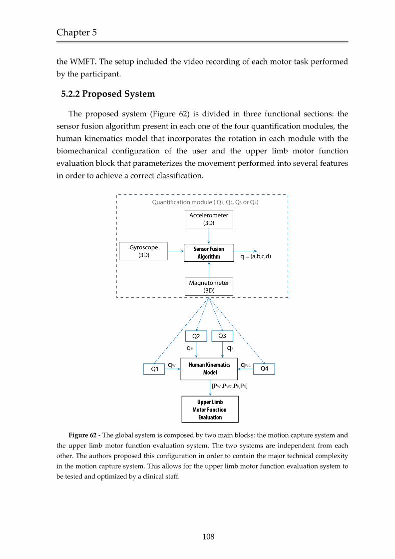
Chapter 5
108
the WMFT. The setup included the video recording of each motor task performed
by the participant.
5.2.2 Proposed System
The proposed system (Figure 62) is divided in three functional sections: the
sensor fusion algorithm present in each one of the four quantification modules, the
human kinematics model that incorporates the rotation in each module with the
biomechanical configuration of the user and the upper limb motor function
evaluation block that parameterizes the movement performed into several features
in order to achieve a correct classification.
Figure 62 - The global system is composed by two main blocks: the motion capture system and
the upper limb motor function evaluation system. The two systems are independent from each
other. The authors proposed this configuration in order to contain the major technical complexity
in the motion capture system. This allows for the upper limb motor function evaluation system to
be tested and optimized by a clinical staff.
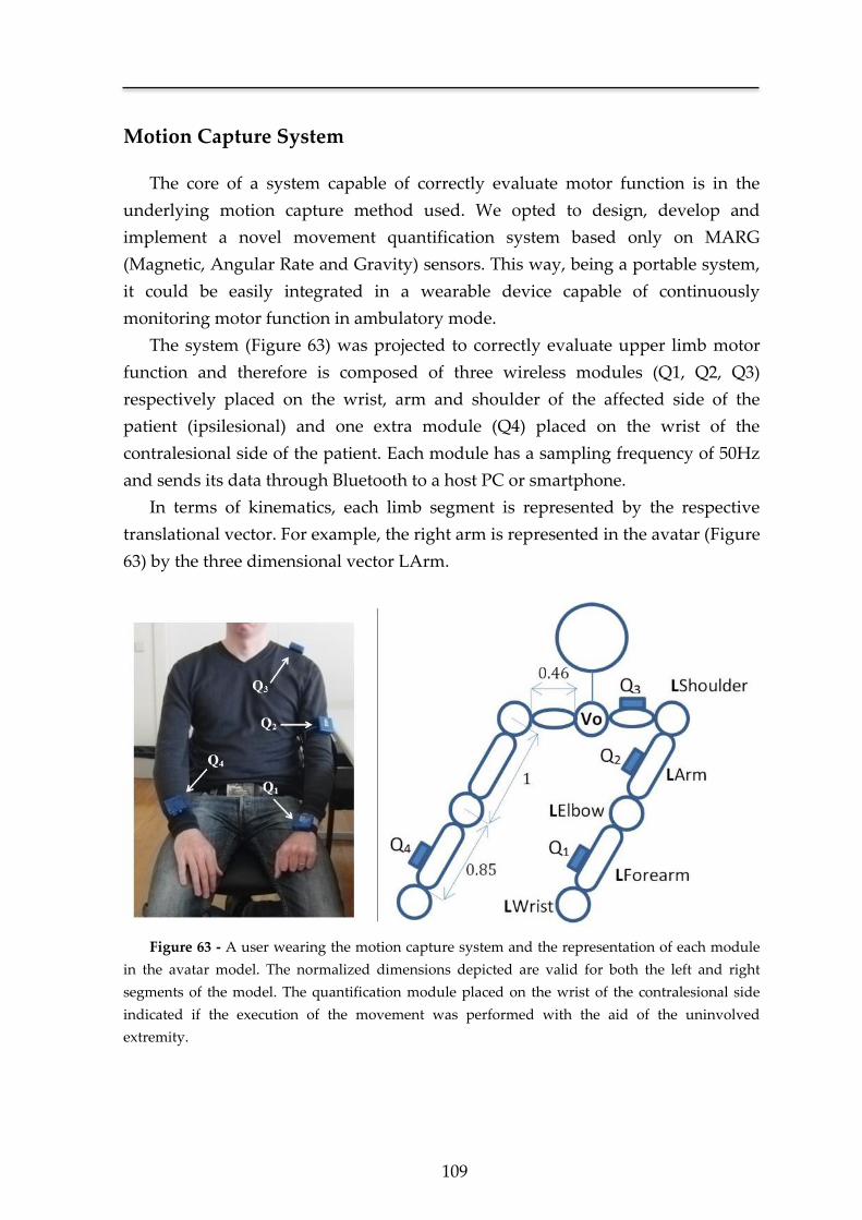
109
Motion Capture System
The core of a system capable of correctly evaluate motor function is in the
underlying motion capture method used. We opted to design, develop and
implement a novel movement quantification system based only on MARG
(Magnetic, Angular Rate and Gravity) sensors. This way, being a portable system,
it could be easily integrated in a wearable device capable of continuously
monitoring motor function in ambulatory mode.
The system (Figure 63) was projected to correctly evaluate upper limb motor
function and therefore is composed of three wireless modules (Q1, Q2, Q3)
respectively placed on the wrist, arm and shoulder of the affected side of the
patient (ipsilesional) and one extra module (Q4) placed on the wrist of the
contralesional side of the patient. Each module has a sampling frequency of 50Hz
and sends its data through Bluetooth to a host PC or smartphone.
In terms of kinematics, each limb segment is represented by the respective
translational vector. For example, the right arm is represented in the avatar (Figure
63) by the three dimensional vector LArm.
Figure 63 - A user wearing the motion capture system and the representation of each module
in the avatar model. The normalized dimensions depicted are valid for both the left and right
segments of the model. The quantification module placed on the wrist of the contralesional side
indicated if the execution of the movement was performed with the aid of the uninvolved
extremity.
Chapter 5
110
As referred in Chapter 4, the length of each segment in the avatar was specified
in terms of normalized dimensions, initializing the length of the arm as 1 and from
this value calculating the shoulder and forearm length based on the ratios
shoulder to arm and forearm to arm.
With this solution there is not only an optimization of the clinical procedure in
terms of complexity and time, but also (and more importantly) it allows for the
creation of a valuable normative database, since different kinematics produced by
different users are suitable for a direct comparison.
As referred in Chapter 4, the rotation of each vector in space is
accomplished with the dot product between the initial vector
( or ), the quaternion representing the actual
orientation of the limb ( , or ) and its conjugate ( ,
or ).
(1)
(2)
(3)
The current three-dimensional position of the shoulder (PS), elbow (PE) and
ipsilesional wrist (PWi) was obtained adding the above translational vectors with
the respective starting point of the segment (see Figure 38). The point V0 was the
model origin and therefore static.
(4)
(5)
(6)
With these three points, the human kinematics model was able to
reproduce any movement executed by the patient’s ipsilesional upper limb in all
three dimensions. Since the position of the contralesional wrist (PWc) was only used
to evaluate whether the uninvolved extremity participated in the motor task, its
position was calculated applying the dot product between the static vector
and the respective quaternion ( ).
111
(7)
This will give the position of the contralesional wrist unreferenced to the
biomechanical model, as intended, since in this particular case we only wanted to
evaluate the quantity and not the quality of the movement.
Upper limb motor function evaluation
The system determines the start of the movement when the absolute
velocity of one of the quantification modules exceeds 2% of peak velocity after
being below this threshold for at least 1s. The end is determined by the moment in
time when, after the start of the movement, the velocity remains zero for at least
1s. From these two markers, it determines the performance time for each task. The
time window of analysis was set to 1s due to the fact that lower values could lead
the system, in case of a non-smooth movement, to prematurely determine its end.
This situation results from the specific typology of a non-smooth movement,
characterized by numerous minor resting states, each one capable of triggering the
end of the movement if a small time window of analysis was selected.
Regarding the functional ability score (FAS), we chose Tasks 1 and 2 (Table
9) to test the proficiency of the system in the automatic assessment of motor
function. This was done according to the WMFT criteria and specific guidelines
provided for scoring the functional ability of movement [172]. For example, a FAS
of 3 is achieved if in the unilateral motor task the “Arm does participate, but
movement is influenced to some degree by synergy or is performed slowly and/or with
effort”. In association with our clinical partners, this guideline was streamlined
into the following decision tree (Figure 64) in order to be incorporated in an
automatic system.
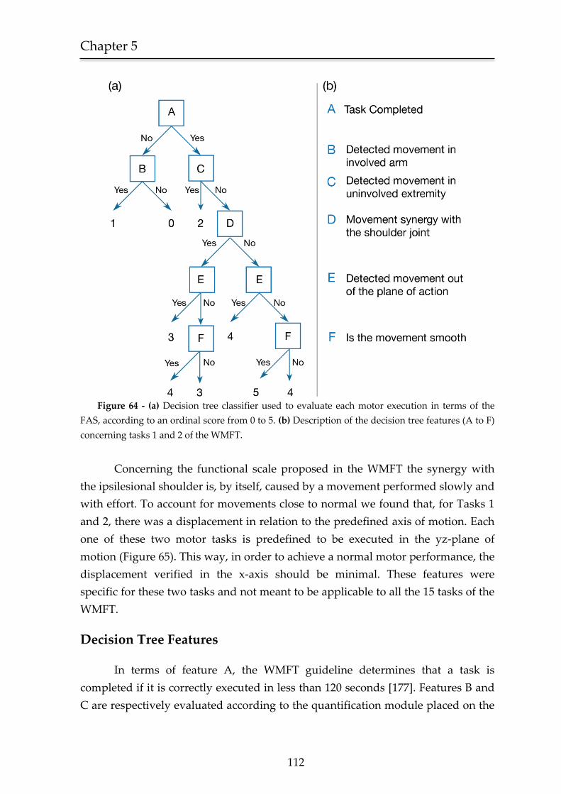
Chapter 5
112
Figure 64 - (a) Decision tree classifier used to evaluate each motor execution in terms of the
FAS, according to an ordinal score from 0 to 5. (b) Description of the decision tree features (A to F)
concerning tasks 1 and 2 of the WMFT.
Concerning the functional scale proposed in the WMFT the synergy with
the ipsilesional shoulder is, by itself, caused by a movement performed slowly and
with effort. To account for movements close to normal we found that, for Tasks 1
and 2, there was a displacement in relation to the predefined axis of motion. Each
one of these two motor tasks is predefined to be executed in the yz-plane of
motion (Figure 65). This way, in order to achieve a normal motor performance, the
displacement verified in the x-axis should be minimal. These features were
specific for these two tasks and not meant to be applicable to all the 15 tasks of the
WMFT.
Decision Tree Features
In terms of feature A, the WMFT guideline determines that a task is
completed if it is correctly executed in less than 120 seconds [177]. Features B and
C are respectively evaluated according to the quantification module placed on the
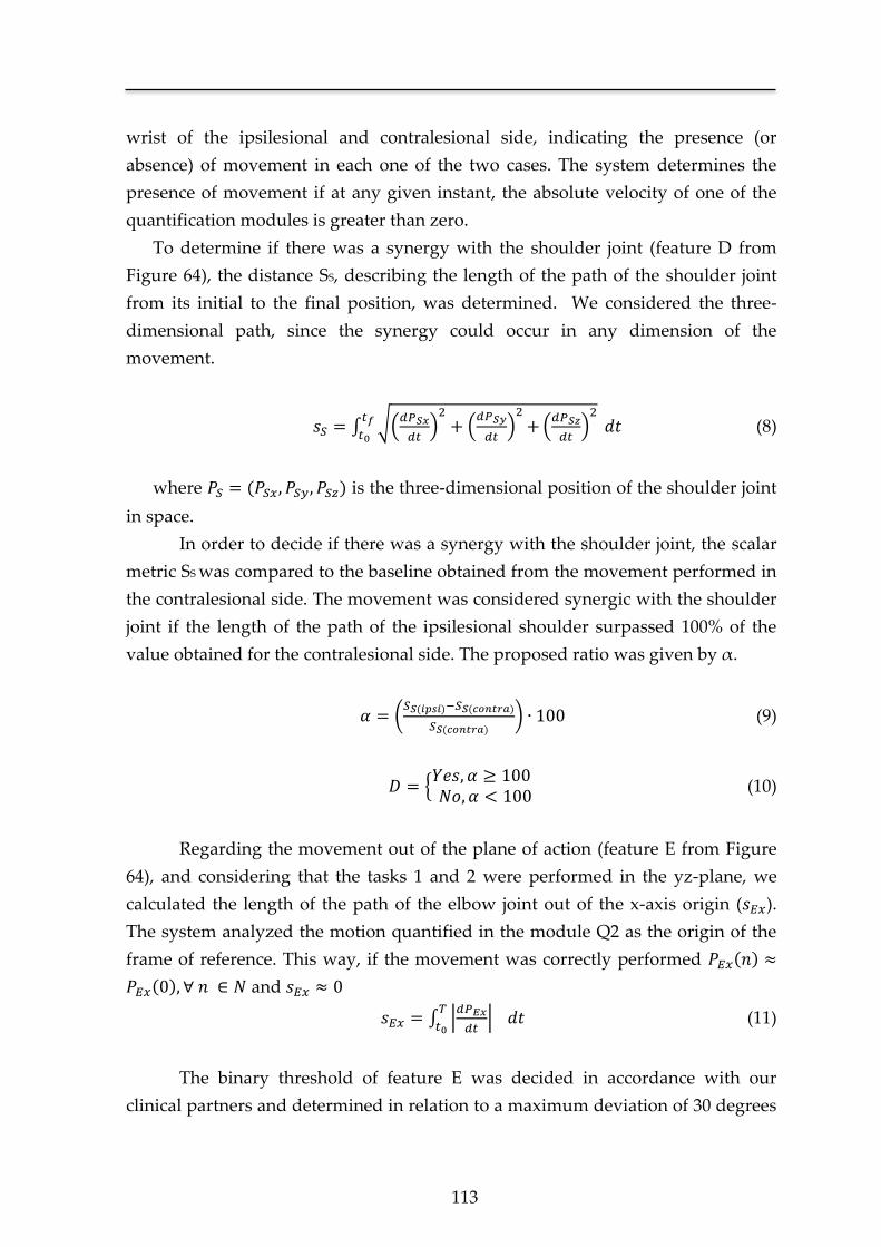
113
wrist of the ipsilesional and contralesional side, indicating the presence (or
absence) of movement in each one of the two cases. The system determines the
presence of movement if at any given instant, the absolute velocity of one of the
quantification modules is greater than zero.
To determine if there was a synergy with the shoulder joint (feature D from
Figure 64), the distance SS, describing the length of the path of the shoulder joint
from its initial to the final position, was determined. We considered the three-
dimensional path, since the synergy could occur in any dimension of the
movement.
∫ √(
) (
)
(
)
(8)
where is the three-dimensional position of the shoulder joint
in space.
In order to decide if there was a synergy with the shoulder joint, the scalar
metric SS was compared to the baseline obtained from the movement performed in
the contralesional side. The movement was considered synergic with the shoulder
joint if the length of the path of the ipsilesional shoulder surpassed 100% of the
value obtained for the contralesional side. The proposed ratio was given by α.
(
) (9)
{
(10)
Regarding the movement out of the plane of action (feature E from Figure
64), and considering that the tasks 1 and 2 were performed in the yz-plane, we
calculated the length of the path of the elbow joint out of the x-axis origin ( ).
The system analyzed the motion quantified in the module Q2 as the origin of the
frame of reference. This way, if the movement was correctly performed
and
∫ |
|
(11)
The binary threshold of feature E was decided in accordance with our
clinical partners and determined in relation to a maximum deviation of 30 degrees
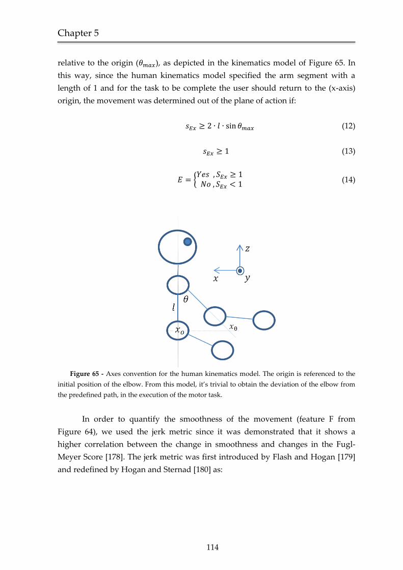
Chapter 5
114
relative to the origin ( ), as depicted in the kinematics model of Figure 65. In
this way, since the human kinematics model specified the arm segment with a
length of 1 and for the task to be complete the user should return to the (x-axis)
origin, the movement was determined out of the plane of action if:
(12)
(13)
{
(14)
Figure 65 - Axes convention for the human kinematics model. The origin is referenced to the
initial position of the elbow. From this model, it’s trivial to obtain the deviation of the elbow from
the predefined path, in the execution of the motor task.
In order to quantify the smoothness of the movement (feature F from
Figure 64), we used the jerk metric since it was demonstrated that it shows a
higher correlation between the change in smoothness and changes in the Fugl-
Meyer Score [178]. The jerk metric was first introduced by Flash and Hogan [179]
and redefined by Hogan and Sternad [180] as:
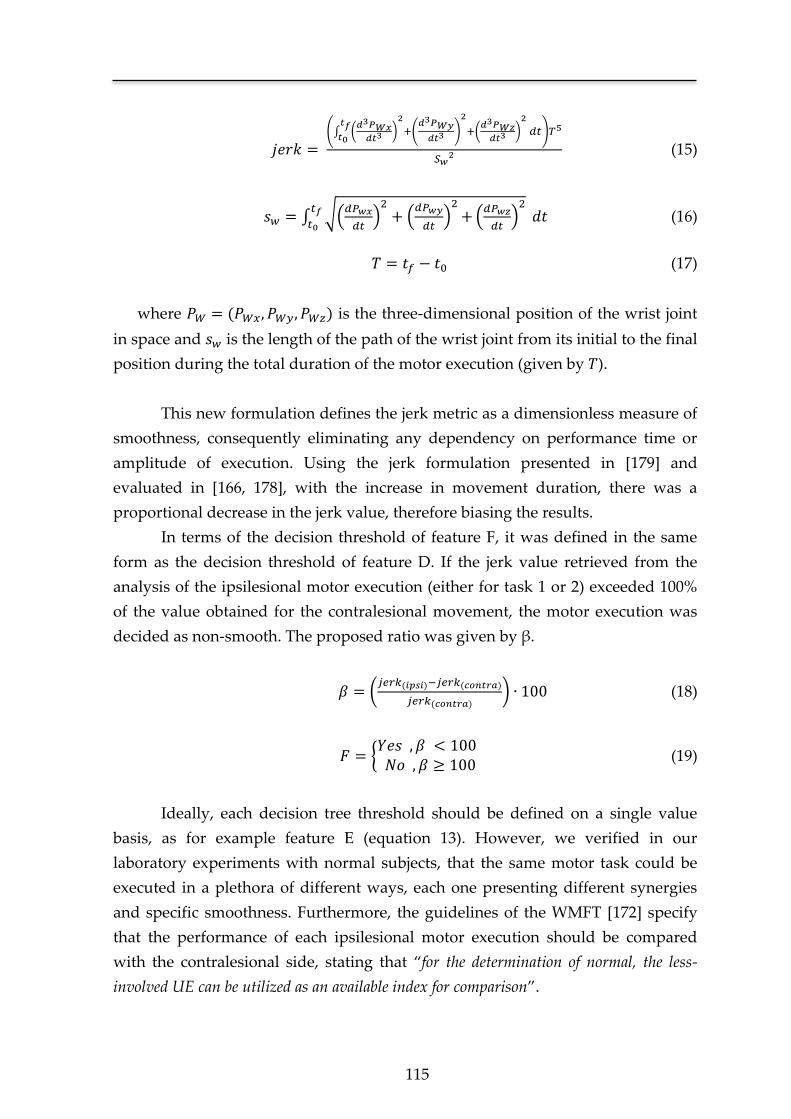
115
(∫ (
)
(
)
(
)
)
(15)
∫ √(
) (
)
(
)
(16)
(17)
where is the three-dimensional position of the wrist joint
in space and is the length of the path of the wrist joint from its initial to the final
position during the total duration of the motor execution (given by ).
This new formulation defines the jerk metric as a dimensionless measure of
smoothness, consequently eliminating any dependency on performance time or
amplitude of execution. Using the jerk formulation presented in [179] and
evaluated in [166, 178], with the increase in movement duration, there was a
proportional decrease in the jerk value, therefore biasing the results.
In terms of the decision threshold of feature F, it was defined in the same
form as the decision threshold of feature D. If the jerk value retrieved from the
analysis of the ipsilesional motor execution (either for task 1 or 2) exceeded 100%
of the value obtained for the contralesional movement, the motor execution was
decided as non-smooth. The proposed ratio was given by β.
(
) (18)
{
(19)
Ideally, each decision tree threshold should be defined on a single value
basis, as for example feature E (equation 13). However, we verified in our
laboratory experiments with normal subjects, that the same motor task could be
executed in a plethora of different ways, each one presenting different synergies
and specific smoothness. Furthermore, the guidelines of the WMFT [172] specify
that the performance of each ipsilesional motor execution should be compared
with the contralesional side, stating that “for the determination of normal, the less-
involved UE can be utilized as an available index for comparison”.
Chapter 5
116
5.2.3 Subjects
The system was tested in five male stroke patients aged between 35 and 73
years old. They were all right handed and were selected from the outpatient stroke
clinic after signing informed consent. All users had a medial cerebral artery
ischemic stroke, were already medically stable, able to sit and stand and had
upper limb motor impairment (three on the right side), but not hemiplegia (able to
actively extend wrist, thumb, and at least 2 other digits >10°). Their motor
performance ranged from near normal (users 1 and 2) to moderate deficit (users 3
to 5) on the impaired limb. Cognitive performance was normal in all users
according to clinical assessment with relatives and Mini Mental state examination
[158].
5.2.4 Procedure
Users received a brief explanation of the tasks depicted in Figure 61 and were
requested to perform them first with the normal side and then with the impaired
side. The clinician was proficient in the WMFT and was asked to score the
movement according to WMFT guidelines being allowed to review the video
recordings of the test later on (ideal clinical scenario). The automatic movement
quantification system operated simultaneously.
5.3 Results
5.3.1 Performance time
The performance time error distribution, between the measures acquired by
the clinician and those achieved by the proposed system, had a mean of 0.17 s and
a standard deviation of 0.14 s. Figure 66 shows representative results for the five
users.
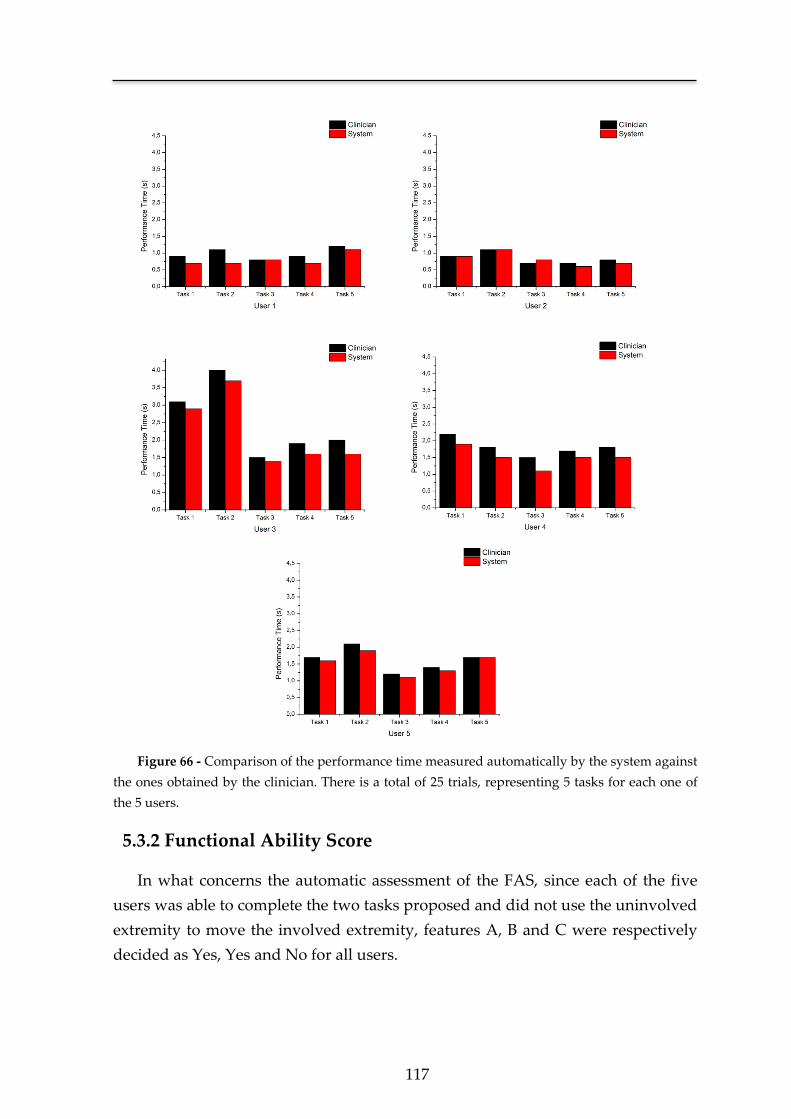
117
Figure 66 - Comparison of the performance time measured automatically by the system against
the ones obtained by the clinician. There is a total of 25 trials, representing 5 tasks for each one of
the 5 users.
5.3.2 Functional Ability Score
In what concerns the automatic assessment of the FAS, since each of the five
users was able to complete the two tasks proposed and did not use the uninvolved
extremity to move the involved extremity, features A, B and C were respectively
decided as Yes, Yes and No for all users.
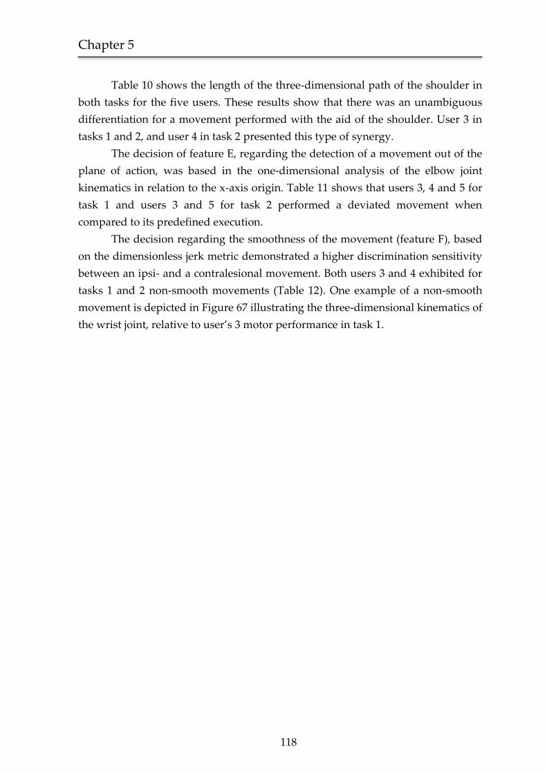
Chapter 5
118
Table 10 shows the length of the three-dimensional path of the shoulder in
both tasks for the five users. These results show that there was an unambiguous
differentiation for a movement performed with the aid of the shoulder. User 3 in
tasks 1 and 2, and user 4 in task 2 presented this type of synergy.
The decision of feature E, regarding the detection of a movement out of the
plane of action, was based in the one-dimensional analysis of the elbow joint
kinematics in relation to the x-axis origin. Table 11 shows that users 3, 4 and 5 for
task 1 and users 3 and 5 for task 2 performed a deviated movement when
compared to its predefined execution.
The decision regarding the smoothness of the movement (feature F), based
on the dimensionless jerk metric demonstrated a higher discrimination sensitivity
between an ipsi- and a contralesional movement. Both users 3 and 4 exhibited for
tasks 1 and 2 non-smooth movements (Table 12). One example of a non-smooth
movement is depicted in Figure 67 illustrating the three-dimensional kinematics of
the wrist joint, relative to user’s 3 motor performance in task 1.
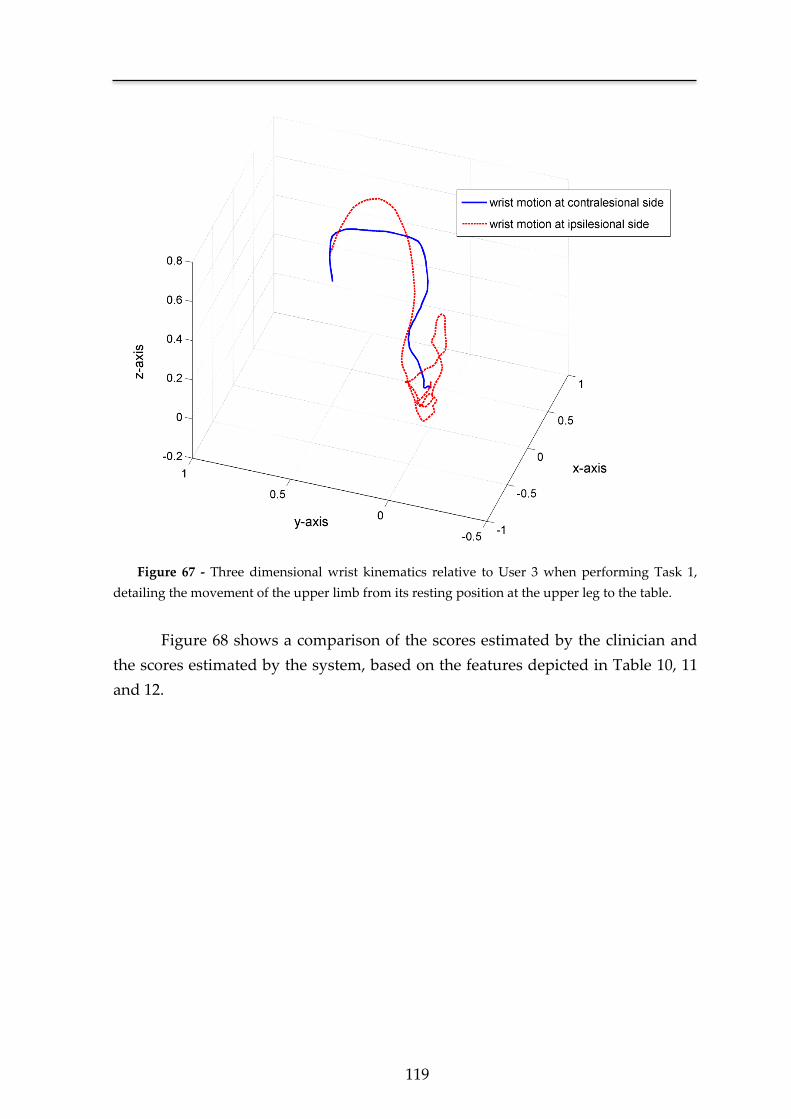
119
Figure 67 - Three dimensional wrist kinematics relative to User 3 when performing Task 1,
detailing the movement of the upper limb from its resting position at the upper leg to the table.
Figure 68 shows a comparison of the scores estimated by the clinician and
the scores estimated by the system, based on the features depicted in Table 10, 11
and 12.
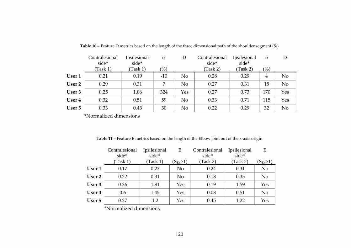
120
Table 10 – Feature D metrics based on the length of the three dimensional path of the shoulder segment (SS)
Contralesional
side*
(Task 1)
Ipsilesional
side*
(Task 1)
α
(%)
D Contralesional
side*
(Task 2)
Ipsilesional
side*
(Task 2)
α
(%)
D
User 1 0.21 0.19 -10 No 0.28 0.29 4 No
User 2 0.29 0.31 7 No 0.27 0.31 15 No
User 3 0.25 1.06 324 Yes 0.27 0.73 170 Yes
User 4 0.32 0.51 59 No 0.33 0.71 115 Yes
User 5 0.33 0.43 30 No 0.22 0.29 32 No
*Normalized dimensions
Table 11 – Feature E metrics based on the length of the Elbow joint out of the x-axis origin
Contralesional
side*
(Task 1)
Ipsilesional
side*
(Task 1)
E
(SEx>1)
Contralesional
side*
(Task 2)
Ipsilesional
side*
(Task 2)
E
(SEx>1)
User 1 0.17 0.23 No 0.24 0.31 No
User 2 0.22 0.31 No 0.18 0.35 No
User 3 0.36 1.81 Yes 0.19 1.59 Yes
User 4 0.6 1.45 Yes 0.08 0.51 No
User 5 0.27 1.2 Yes 0.45 1.22 Yes
*Normalized dimensions
121
Table 12 – Feature F metrics (dimensionless jerk)
Contralesional
side*
(Task 1)
Ipsilesional
side*
(Task 1)
β
(%)
F Contralesional
side*
(Task 2)
Ipsilesional
side*
(Task 2)
β
(%)
F
User 1 1.03x10⁷ 8.98x10⁶ -13 Yes 5.31x10⁶ 6.27x10⁶ 18 Yes
User 2 4.27x10⁶ 5.32x10⁶ 25 Yes 3.57x10⁶ 4.25x10⁶ 19 Yes
User 3 3.78x10⁷ 7.68x10⁸ 1931 No 4.94x10⁷ 2.20x10⁸ 345 No
User 4 1.62x10⁷ 2.58x10⁸ 1492 No 3.75x10⁷ 1.07x10⁸ 185 No
User 5 4.39x10⁷ 5.23x10⁷ 19 Yes 2.13x10⁷ 2.66x10⁷ 25 Yes
* Normalized dimensions
Figure 68 - Functional ability scores for the 5 users in: (a) Task 1 “forearm to table”; (b) Task 2 “forearm to box”.
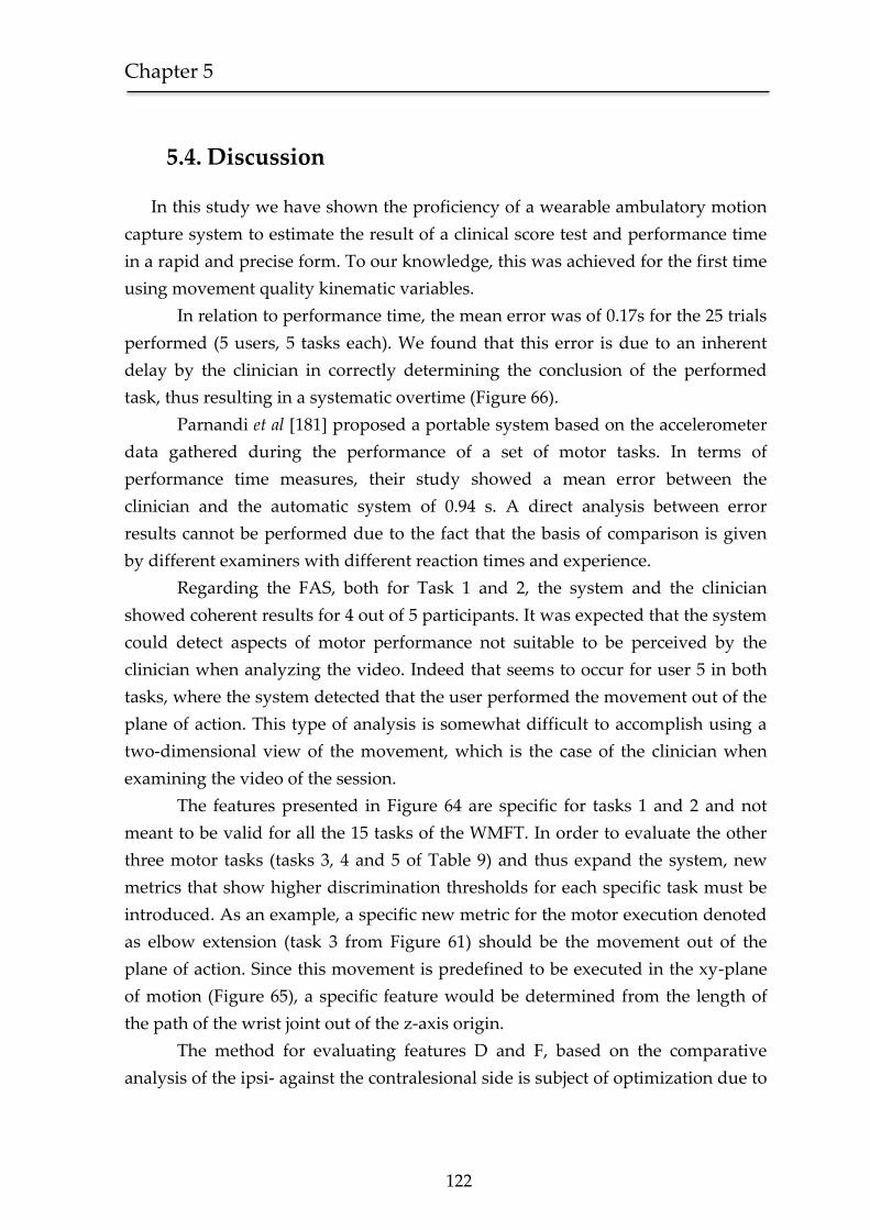
Chapter 5
122
5.4. Discussion
In this study we have shown the proficiency of a wearable ambulatory motion
capture system to estimate the result of a clinical score test and performance time
in a rapid and precise form. To our knowledge, this was achieved for the first time
using movement quality kinematic variables.
In relation to performance time, the mean error was of 0.17s for the 25 trials
performed (5 users, 5 tasks each). We found that this error is due to an inherent
delay by the clinician in correctly determining the conclusion of the performed
task, thus resulting in a systematic overtime (Figure 66).
Parnandi et al [181] proposed a portable system based on the accelerometer
data gathered during the performance of a set of motor tasks. In terms of
performance time measures, their study showed a mean error between the
clinician and the automatic system of 0.94 s. A direct analysis between error
results cannot be performed due to the fact that the basis of comparison is given
by different examiners with different reaction times and experience.
Regarding the FAS, both for Task 1 and 2, the system and the clinician
showed coherent results for 4 out of 5 participants. It was expected that the system
could detect aspects of motor performance not suitable to be perceived by the
clinician when analyzing the video. Indeed that seems to occur for user 5 in both
tasks, where the system detected that the user performed the movement out of the
plane of action. This type of analysis is somewhat difficult to accomplish using a
two-dimensional view of the movement, which is the case of the clinician when
examining the video of the session.
The features presented in Figure 64 are specific for tasks 1 and 2 and not
meant to be valid for all the 15 tasks of the WMFT. In order to evaluate the other
three motor tasks (tasks 3, 4 and 5 of Table 9) and thus expand the system, new
metrics that show higher discrimination thresholds for each specific task must be
introduced. As an example, a specific new metric for the motor execution denoted
as elbow extension (task 3 from Figure 61) should be the movement out of the
plane of action. Since this movement is predefined to be executed in the xy-plane
of motion (Figure 65), a specific feature would be determined from the length of
the path of the wrist joint out of the z-axis origin.
The method for evaluating features D and F, based on the comparative
analysis of the ipsi- against the contralesional side is subject of optimization due to
123
the fact that it represents the classical problem of evaluating normality. The use of
normative data is very common when pondering the results of neuropsychological
assessment tests [182], designed to measure the psychological function of a user,
comparing the score obtained with a sample drawn from a general population
representing the user. This normative sample is segmented according to age, level
of education, ethnical background and others. The optimization of the ratio
thresholds for α and β, allowing a more general discrimination between what’s
normal for two different users, must be based on such a data sample obtained
from a large clinical trial composed by users assumed, in terms of motor
performance, as normal.
5.5 Conclusions
The automatic assessment of motor function based on the use of movement
quality kinematic variables has been demonstrated to be of valid use in regular
clinical practice by Subramanian et al [74]. The proposed system could save time
being suited to be applied in a rapid form providing a higher accuracy due to the
analysis of the movement in all its’ three dimensional projections.
These preliminary results demonstrate that our system is capable of
correctly determining the performance time of each motor task. Furthermore, in
terms of the FAS, when compared against the clinical scores obtained after video
reviewing, the system is, concordant with the clinician in 4 out of 5 users.
Apart from the importance of the proof of concept demonstrated in this
study, one should keep in mind that all clinical procedures developed to date
where specifically suited to be performed by a clinician and therefore do not take
advantage of the full potential of a 3D motion capture system. Several important
features such as the acceleration on the start and end of the movement should be
included. This way, it is our opinion that the development of a system capable of
automatic assessment of motor function after neurologic injury should be based on
the combination of clinical knowledge provided by traditional examination tests
with the more refined capabilities of 3D motion capture systems.
Such a system, as proposed earlier, based on normalized data, and
evaluated using a quantitative method should progress in close proximity with
what happens in the psychometric field of research based on the combination of
both a quantitative analysis and a scalar definition of normal.
Chapter 5
124
In addition, the motion capture system was designed to be totally portable
being easily assembled in a wearable garment. This way, the system is suited to be
integrated in an ambulatory framework allowing clinicians to continuously
document the recovery of the patient and subsequently adjust the rehabilitation
plan leading to a more effective prescription of medications. Such an ambulatory
framework would improve the quality of the rehabilitation plan not only on stroke
patients and other brain injury conditions, but also on neurodegenerative
pathologies such as Parkinson’s disease [183] and other movement disorders.
As a concluding remark, it should be noted that the proof-of-concept presented
herein is not intended to be considered as a definitive evidence of the system’s
proficiency in the evaluation of motor function. This work represents a first step
towards the acceptance of a new paradigm, which naturally must be first target of
discussion so that a solid solution could emerge from a multidisciplinary
perspective.


Chapter 6 Conclusion and Future work

Chapter 6
126
The recovery of motor function after a neurological accident (e.g. Stroke) is still
an open problem. Its inherent complexity derives from the several constraints
present that hinder an effective solution to be found. The proficiency of a
rehabilitation methodology is not only measured in terms of the recovery of the
motor function of the patient, but as a combination of improvement, cost and
safety. The promising arena of pharmacology must be complemented with equally
effective solutions in the physical therapy field. Only from a parallel evolution in
these two areas it is possible to create a concrete intervention capable of a
widespread use [184].
As in any complex problem, a green field of opportunities emerges from its
solution. This thesis was focused on the invention of a novel medical device
capable of providing an effective rehabilitation to Stroke patients. From the start,
the constraints of safety and cost where always present in each step taken. In
Chapter 3 we studied the tolerability of the vibratory stimulus stimulating
hemiparetic Stroke patients with a target vibratory stimulus during a five-hour
period. This told us that the use of a haptic interface was safe and didn’t provide
any discomfort to the patient.
The design of the SWORD device described in Chapter 4 shows several
different levels of abstraction each one presenting a different degree of complexity.
The most challenging period in the invention of the SWORD device was the
development of the movement quantification system. Using the proposed
approach we have shown that it is possible to create a tool able to acquire the
human motion dynamics in a low-cost, comfortable and portable form. Such a
system opens a wide range of new possibilities either in the medical and
mainstream field of applications. The last chapter discussed the development of a
system capable of an automatic evaluation of upper-limb motor function after
neurological injury. This framework represents a possible solution for an
underestimated but important problem in neurorehabilitation: why state-of-art
clinical trials in neurology have failed to deliver treatments. Hobart. et al [164]
centered the problem in the fact that the numbers generated by most rating scales
do not satisfy the criteria for rigorous measurements. Additionally, it is not clear
which variables most rating scales measure. A system capable of evaluating motor
performance based not on an ordinal scale ambiguously evaluated by a clinician,
but in a set of known metrics that are replicable in each test taken, would
represent a significant advance in this area and a valuable tool in clinical trials.
Furthermore, it would allow for an efficient documentation of a patient’s
127
improvement during the recovery process, providing valuable insights to the
medical field and enabling a clear perception of the underlying CNS’s mechanisms
that support an efficient motor recovery. In terms of future work, an extended
validation of the preliminary results obtained must be conducted, testing the
system’s proficiency on a large sample combining both normal users and patients,
comparing the timing and FAS of the system against a global assessment
performed by a board of clinicians presenting different experiences (measured in
number of years of clinical practice). This way, a clear comparison and possible
correlation between the experience of each clinician, subsequent scoring and the
system results could be achieved. This data would provide a more detailed insight
regarding, not only the accuracy of the system, but also the accuracy of the
different clinicians. Future directions of development also include a detailed
verification of the proficiency of the motion capture system developed when
compared against similar systems [185, 186], under the same conditions.
The evolution of the SWORD device will derive from a combined process of
optimization and development of new features. A pioneering therapy can be
devised, incorporating in a single package both processes of motor and cognitive
rehabilitation. The expansion of the SWORD device in a complete tele-
rehabilitation system supports this intervention. Merging the current capabilities
of the motion quantification system with the latest advances in computer game
technology, it is possible to include in a single exercise both aspects of cognitive
and motor training. Another line of research that must be pursued is in the
development of a system that, integrated with the SWORD device, permits the
recovery of hand movement. This system should follow the conceptual model
depicted in Chapter 4, training both simple tasks (analyzing the range-of-
movement for each finger) and complex ones (comparing the performed
movement with a reference).
The study of the relation between the vibratory stimulus applied and the level
of excitation provoked in the CNS is crucial to perceive if it is possible to define an
optimal frequency and amplitude of vibration. The definition of optimal in this
context is specified for a stimulus that will maximize compliance without
becoming uncomfortable. One possible implementation for such a study is in the
perception of the functional magnetic resonance imaging (fMRI) activation maps
that result from a set of different types of vibratory stimulus.
The work that supports this PhD thesis was praised by the scientific, technical
and clinical community, through the papers already published in major peer
Chapter 6
128
reviewed international conferences and journals. The SWORD tele-rehabilitation
system was awarded with the Highest Future Impact honor in the demo
competition on wearable & ubiquitous technology for health and wellness, part of
the 33rd Annual International Conference of the IEEE Engineering in Medicine
and Biology Society (EMBC ’11). The intellectual property in the SWORD device is
protected by its pending patent and the work [187] depicted in Chapter 5, relative
to the development of a system capable of automatic evaluation of motor function,
was selected as an open-finalist in the Student Paper Competition of the 33rd
Annual International Conference of the IEEE Engineering in Medicine and Biology
Society (EMBC ’11). The work herein presented includes three different
experiments enrolling a total of 15 different stroke patients and a large team of
physicians, nurses and medical doctors at the Hospital of São Sebastião.
In spite of these recognitions, we are still in the middle of our journey.
Currently, a randomized clinical trial is being devised to assess the proficiency of
the SWORD device in the restoration of motor function in the upper-limb. There is
much to learn from the independent use of the SWORD device in ambulatory by
patients and their relatives. No doubt that from this experience, unpredictable
challenges will appear that must be addressed correctly in order to implement the
SWORD device as a real solution.
I look forward to the day when the SWORD device becomes a main research
line in the medical field. When its underlying technology is made transparent and
the main topic of discussion is the study and validation of new motor tasks to
parameterize in the system. From this discussion, there will certainly appear new
solutions from which I am now completely blind.

Bibliography
[1] M. Correia, et al., "Prospective community-based study of stroke in
Northern Portugal: incidence and case fatality in rural and urban
populations," Stroke, vol. 35, pp. 2048-53, Sep 2004.
[2] A. Timmermans, et al., "Arm and hand skills: Training preferences after
stroke," Disability and Rehabilitation, vol. 31, pp. 1344-1352, 2009.
[3] Brocair Partners LLC, "Overview of the Outpatient Rehabilitation Market,"
New York, USA, 2011.
[4] S. S. Rathore, et al., "Characterization of incident stroke signs and
symptoms: findings from the atherosclerosis risk in communities study,"
Stroke, vol. 33, pp. 2718-21, Nov 2002.
[5] B. H. Dobkin, "Strategies for stroke rehabilitation," Lancet Neurol, vol. 3, pp.
528-36, Sep 2004.
[6] G. J. Hankey, et al., "Time frame and predictors of recovery from disability
following recurrent ischemic stroke," Neurology, vol. 68, pp. 202-5, Jan 16
2007.
[7] L. Kalra, "Stroke Rehabilitation 2009: Old Chestnuts and New Insights,"
Stroke, vol. 41, pp. e88-90, February 1, 2010 2010.
[8] M. Kononen, et al., "Increased perfusion in motor areas after constraint-
induced movement therapy in chronic stroke: a single-photon emission
computerized tomography study," J Cereb Blood Flow Metab, vol. 25, pp.
1668-74, Dec 2005.
[9] W. Liu, et al., "Noise-enhanced vibrotactile sensitivity in older adults,
patients with stroke, and patients with diabetic neuropathy," Arch Phys Med
Rehabil, vol. 83, pp. 171-6, Feb 2002.
[10] A. A. Priplata, et al., "Noise-enhanced balance control in patients with
diabetes and patients with stroke," Ann Neurol, vol. 59, pp. 4-12, Jan 2006.
[11] M. A. Rothenberg, et al., Dictionary of Medical Terms: Barron's Educational
Series, 2006.
[12] S. C. Cramer, "Repairing the human brain after stroke: I. Mechanisms of
spontaneous recovery," Ann Neurol, vol. 63, pp. 272-87, Mar 2008.
[13] P. Langhorne, et al., "Stroke rehabilitation," The Lancet, vol. 377, pp. 1693-
1702, 2011.
Bibliography
130
[14] C. Younggeun, et al., "An Adaptive Automated Robotic Task-Practice
System for Rehabilitation of Arm Functions After Stroke," Robotics, IEEE
Transactions on, vol. 25, pp. 556-568, 2009.
[15] H. I. Krebs, et al., "Robot-Aided Neurorehabilitation: A Robot for Wrist
Rehabilitation," Neural Systems and Rehabilitation Engineering, IEEE
Transactions on, vol. 15, pp. 327-335, 2007.
[16] P. S. Lum, et al., "The MIME robotic system for upper-limb neuro-
rehabilitation: results from a clinical trial in subacute stroke," in
Rehabilitation Robotics, 2005. ICORR 2005. 9th International Conference on,
2005, pp. 511-514.
[17] H. Schmidt, et al., "Upper and lower extremity robotic devices to promote
motor recovery after stroke -recent developments," in Engineering in
Medicine and Biology Society, 2004. IEMBS '04. 26th Annual International
Conference of the IEEE, 2004, pp. 4825-4828.
[18] S. Hesse, et al., "A new electromechanical trainer for sensorimotor
rehabilitation of paralysed fingers: A case series in chronic and acute stroke
patients," Journal of NeuroEngineering and Rehabilitation, vol. 5, p. 21, 2008.
[19] X. L. Hu, et al., "A Comparison Between Electromyography-Driven Robot
and Passive Motion Device on Wrist Rehabilitation for Chronic Stroke,"
Neurorehabilitation and Neural Repair, vol. 23, pp. 837-846, 2009.
[20] R. P. Van Peppen, et al., "The impact of physical therapy on functional
outcomes after stroke: what's the evidence?," Clin Rehabil, vol. 18, pp. 833-
862, 2004.
[21] P. Langhorne, et al., "Motor recovery after stroke: a systematic review," The
Lancet Neurology, vol. 8, pp. 741-754, 2009.
[22] L. Oujamaa, et al., "Rehabilitation of arm function after stroke. Literature
review," Annals of Physical and Rehabilitation Medicine, vol. 52, pp. 269-293,
2009.
[23] S. Finger, Minds Behind the Brain: A History of the Pioneers and Their
Discoveries, 1st Edition ed.: Oxford University Press Inc, 2000.
[24] J. M. CHARCOT, "Vibratory Therapeutics.-the Application of Rapid and
Continuous Vibrations To the Treatment of Certain Diseases of the Nervous
System," The Journal of Nervous and Mental Disease, vol. 17, pp. 880-886, 1892.
[25] C. G. Goetz, "Jean-Martin Charcot and his vibratory chair for Parkinson
disease," Neurology, vol. 73, pp. 475-478, August 11, 2009 2009.
[26] P. Meyer, et al., "The role of plantar cutaneous sensation in unperturbed
stance," Experimental Brain Research, vol. 156, pp. 505-512, 2004.
[27] I. J. W. van Nes, et al., "Short-Term Effects of Whole-Body Vibration on
Postural Control in Unilateral Chronic Stroke Patients: Preliminary
Evidence," American Journal of Physical Medicine & Rehabilitation, vol. 83, pp.
867-873, 2004.
131
[28] I. J. van Nes, et al., "Long-term effects of 6-week whole-body vibration on
balance recovery and activities of daily living in the postacute phase of
stroke: a randomized, controlled trial," Stroke, vol. 37, pp. 2331-5, Sep 2006.
[29] C. T. Haas, et al., "The effects of random whole-body-vibration on motor
symptoms in Parkinson's disease," NeuroRehabilitation, vol. 21, pp. 29-36,
2006.
[30] P. Arias, et al., "Effect of whole body vibration in Parkinson's disease: A
controlled study," Movement Disorders, vol. 24, pp. 891-898, 2009.
[31] G. Ebersbach, et al., "Whole Body Vibration Versus Conventional
Physiotherapy to Improve Balance and Gait in Parkinson’s Disease,"
Archives of physical medicine and rehabilitation, vol. 89, pp. 399-403, 2008.
[32] K. Kawahira, et al., "New functional vibratory stimulation device for
extremities in patients with stroke," International Journal of Rehabilitation
Research, vol. 27, 2004.
[33] I. Shirahashi, et al., "Functional vibratory stimulation on the hand facilitates
voluntary movements of a hemiplegic upper limb in a patient with stroke,"
International Journal of Rehabilitation Research, vol. 30, 2007.
[34] M. M. Chakravarty, et al., "Robust S1, S2, and thalamic activations in
individual subjects with vibrotactile stimulation at 1.5 and 3.0 T," Human
Brain Mapping, vol. 30, pp. 1328-1337, 2009.
[35] S. T. Francis, et al., "fMRI of the Responses to Vibratory Stimulation of Digit
Tips," NeuroImage, vol. 11, pp. 188-202, 2000.
[36] S. M. Golaszewski, et al., "Functional Magnetic Resonance Imaging of the
Human Sensorimotor Cortex Using a Novel Vibrotactile Stimulator,"
NeuroImage, vol. 17, pp. 421-430, 2002.
[37] R. J. Seitz and P. E. Roland, "Vibratory stimulation increases and decreases
the regional cerebral blood flow and oxidative metabolism: a positron
emission tomography (PET) study," Acta Neurologica Scandinavica, vol. 86,
pp. 60-67, 1992.
[38] M. O. Conrad, et al., "Effects of Wrist Tendon Vibration on Targeted Upper-
Arm Movements in Poststroke Hemiparesis," Neurorehabilitation and Neural
Repair, vol. 25, pp. 61-70, 2011.
[39] R. J. Nudo, "Mechanisms for recovery of motor function following cortical
damage," Current Opinion in Neurobiology, vol. 16, pp. 638-644, 2006.
[40] J. H. Kaas and C. E. Collins, "The organization of sensory cortex," Current
Opinion in Neurobiology, vol. 11, pp. 498-504, 2001.
[41] C. L. Ojakangas, et al., "Decoding Movement Intent From Human Premotor
Cortex Neurons for Neural Prosthetic Applications," Journal of Clinical
Neurophysiology, vol. 23, pp. 577-584 10.1097/01.wnp.0000233323.87127.14,
2006.
Bibliography
132
[42] J. P. Donoghue, et al., "Organization of the forelimb area in squirrel monkey
motor cortex: representation of digit, wrist, and elbow muscles,"
Experimental Brain Research, vol. 89, pp. 1-19, 1992.
[43] M. S. Jones and D. S. Barth, "Sensory-evoked high-frequency ([gamma]-
band) oscillating potentials in somatosensory cortex of the unanesthetized
rat," Brain Research, vol. 768, pp. 167-176, 1997.
[44] M. M. G. E.R. Ergenzinger, J.O. Hahm, T.P. Pons, "Cortically induced
thalamic plasticity in the primate somatosensory system " Nature
Neuroscience, vol. 1, p. 4, 1998.
[45] J. Liepert, et al., "Changes of cortical motor area size during
immobilization," Electroencephalography and Clinical
Neurophysiology/Electromyography and Motor Control, vol. 97, pp. 382-386,
1995.
[46] Y. Liu and E. M. Rouiller, "Mechanisms of recovery of dexterity following
unilateral lesion of the sensorimotor cortex in adult monkeys," Experimental
Brain Research, vol. 128, pp. 149-159, 1999.
[47] J. K. Douglass, et al., "Noise enhancement of information transfer in crayfish
mechanoreceptors by stochastic resonance," Nature, vol. 365, pp. 337-40, Sep
23 1993.
[48] Q. Huang, et al., "A modified adaptive Stochastic resonance for detecting
faint signal in sensors," Sensors, vol. 7, pp. 157-165, Feb 2007.
[49] M. Bortolomasi, et al., "Long-lasting effects of high frequency repetitive
transcranial magnetic stimulation in major depressed patients," Psychiatry
Research, vol. 150, pp. 181-186, 2007.
[50] E. M. Khedr, et al., "Modulation of motor cortical excitability following
rapid-rate transcranial magnetic stimulation," Clinical Neurophysiology, vol.
118, pp. 140-145, 2007.
[51] F. Fregni, et al., "A randomized clinical trial of repetitive transcranial
magnetic stimulation in patients with refractory epilepsy," Ann Neurol, vol.
60, pp. 447-455, 2006.
[52] R. Sparing and F. M. Mottaghy, "Noninvasive brain stimulation with
transcranial magnetic or direct current stimulation (TMS/tDCS)—From
insights into human memory to therapy of its dysfunction," Methods, vol.
44, pp. 329-337, 2008.
[53] F. Fregni, et al., "A Sham-Controlled Trial of a 5-Day Course of Repetitive
Transcranial Magnetic Stimulation of the Unaffected Hemisphere in Stroke
Patients," Stroke, vol. 37, pp. 2115-2122, 2006.
[54] N. Takeuchi, et al., "Repetitive Transcranial Magnetic Stimulation of
Contralesional Primary Motor Cortex Improves Hand Function After
Stroke," Stroke, vol. 36, pp. 2681-2686, 2005.
133
[55] M. R. Popovic, et al., "Functional Electrical Stimulation Therapy of
Voluntary Grasping Versus Only Conventional Rehabilitation for Patients
With Subacute Incomplete Tetraplegia," Neurorehabilitation and Neural
Repair, vol. 25, pp. 433-442, 2011.
[56] S. K. Stackhouse, et al., "Neuromuscular Electrical Stimulation Versus
Volitional Isometric Strength Training in Children With Spastic Diplegic
Cerebral Palsy: A Preliminary Study," Neurorehabilitation and Neural Repair,
vol. 21, pp. 475-485, 2007.
[57] J. J. Daly, et al., "A Randomized Controlled Trial of Functional
Neuromuscular Stimulation in Chronic Stroke Subjects," Stroke, vol. 37, pp.
172-178, 2006.
[58] J. Bronzino and B. Bronzino, The Biomedical Engineering Handbook Third
Edition ed.: Crc Pr Inc, 2006.
[59] Levy R, et al., "Cortical stimulation for upper-extremity hemiparesis from
ischemic stroke: Everest Study primary endpoint results.," in International
Stroke Conference, New Orleans, LA, 2008.
[60] D. Purves, et al., Neuroscience, 4th Edition ed.: Sinauer Associates, 2007.
[61] S. Weinstein, "Intensive and extensive aspects of tactile sensitivity as a
function of body part, sex, and laterality," in The Skin Senses, ed, 1968, pp.
195-222.
[62] S. M. Golaszewski, et al., "Human brain structures related to plantar
vibrotactile stimulation: A functional magnetic resonance imaging study,"
NeuroImage, vol. 29, pp. 923-929, 2006.
[63] D. A. Ettlin, et al., "Cortical Activation Resulting from Painless Vibrotactile
Dental Stimulation Measured by Functional Magnetic Resonance Imaging
(fMRI)," Journal of Dental Research, vol. 83, pp. 757-761, 2004.
[64] Aristotle, Parts of animals ; Movement of animals ; Progression of animals.
Translated by Peck. A. Harvard: Harvard University Press, 1968.
[65] I. Newton, The Principia, Translated by Andrew Motte: Prometheus Books,
1995.
[66] R. Descartes, Oeuvres de Descartes: BiblioBazaar, 2009.
[67] G. A. Borelli, On the movement of animals: Springer-Verlag, 1989.
[68] R. Baker, "The history of gait analysis before the advent of modern
computers," Gait & posture, vol. 26, pp. 331-342, 2007.
[69] W. E. Weber and E. Weber, Mechanik der menschlichen Gehwerkzeuge: eine
anatomisch-physiologische Untersuchung: Dieterich, 1836.
[70] G. Carlet, "Essai experimental sur la locomotion humaine, etude de la
marche. ," Annales des Sciences Naturelles: Zoologie, p. 15, 1872.
[71] E. J. Marey, "De La Mesure Dans Les Differents Acts De La Locomotion,"
Comptes Rendues de l'Academi des Sciences de Paris, vol. 97, pp. 820-825, 1883.
[72] V. T. Inman, et al., Human walking: Williams & Wilkins, 1981.
Bibliography
134
[73] J. Saunders, et al., "The major determinants in normal and pathological
gait," J Bone Joint Surg, vol. 35A, pp. 543-728, 1953.
[74] S. K. Subramanian, et al., "Validity of Movement Pattern Kinematics as
Measures of Arm Motor Impairment Poststroke," Stroke, vol. 41, pp. 2303-
2308, October 1, 2010 2010.
[75] L. Zhanjian, et al., "Movement quantification in epileptic seizures: a new
approach to video-EEG analysis," Biomedical Engineering, IEEE Transactions
on, vol. 49, pp. 565-573, 2002.
[76] J. P. Silva Cunha, et al., "Movement quantification during epileptic seizures:
a new technical contribution to the evaluation of seizure semiology," in
Engineering in Medicine and Biology Society, 2003. Proceedings of the 25th
Annual International Conference of the IEEE, 2003, pp. 671-673 Vol.1.
[77] R. O'Dwyer, et al., "Lateralizing Significance of Quantitative Analysis of
Head Movements before Secondary Generalization of Seizures of Patients
with Temporal Lobe Epilepsy," Epilepsia, vol. 48, pp. 524-530, 2007.
[78] J. P. S. Cunha, et al., "Movement quantification in epileptic seizures: A
feasibility study for a new 3D approach," Medical Engineering & Physics.
[79] M. Hong, et al., "A Kinematic and Electromyographic Analysis of Turning
in People With Parkinson Disease," Neurorehabilitation and Neural Repair,
vol. 23, pp. 166-176, 2009.
[80] G. Welch and E. Foxlin, "Motion tracking: no silver bullet, but a respectable
arsenal," Computer Graphics and Applications, IEEE, vol. 22, pp. 24-38, 2002.
[81] Vicon Motion Systems Limited, "Vicon MX Hardware - System Reference,"
ed. 5419 McConnel Avenue, Los Angeles, CA 90066, USA, 2004.
[82] J. P. S. Cunha, et al., "Movement Quantification in Epileptic Seizures:
A!feasibility study for a new 3D approach " Medical Engineering & Physics
(Accepted for publication), 2012.
[83] Animazoo, "Gypsy 7 Brochure," ed. Quayside Offices, Basin Road South,
Brighton, UK, 2011.
[84] Xsens Technologies B. V., "MTi and MTx User Manual and Technical
Documentation.," ed. Pantheon 6a, 7521 PR Enschede, The Netherlands,
2009.
[85] D. Purves, et al., Neuroscience: Sinauer Associates, Inc., 2011.
[86] J. Green and D. Krakauer. (2003) New iMEMS Angular Rate Sensing
Gyroscope. Analog Dialogue.
[87] B. Minhang, "Chapter 1 - Introduction to MEMS Devices," in Analysis and
Design Principles of MEMS Devices, ed Amsterdam: Elsevier Science, 2005,
pp. 1-32.
[88] V. Kempe, Inertial MEMS: Principles and Practice: Cambridge University
Press, 2011.
135
[89] D. Titterton and J. Weston, "Strapdown inertial navigation technology - 2nd
edition - [Book review]," Aerospace and Electronic Systems Magazine, IEEE,
vol. 20, pp. 33-34, 2005.
[90] R. E. Kalman, "A new approach to linear filtering and prediction problems,"
Journal of Basic Engineering, pp. 35-45, 1960.
[91] J. L. Marins, et al., "An extended Kalman filter for quaternion-based
orientation estimation using MARG sensors," in Intelligent Robots and
Systems, 2001. Proceedings. 2001 IEEE/RSJ International Conference on, 2001,
pp. 2003-2011 vol.4.
[92] D. Jurman, et al., "Calibration and data fusion solution for the miniature
attitude and heading reference system," Sensors and Actuators A: Physical,
vol. 138, pp. 411-420, 2007.
[93] M. Haid and J. Breitenbach, "Low cost inertial orientation tracking with
Kalman filter," Applied Mathematics and Computation, vol. 153, pp. 567-575,
2004.
[94] H. J. Luinge and P. H. Veltink, "Measuring orientation of human body
segments using miniature gyroscopes and accelerometers," Medical &
biological engineering & computing, vol. 43, pp. 273-282, 2005.
[95] A. M. Sabatini, "Kalman-Filter-Based Orientation Determination Using
Inertial/Magnetic Sensors: Observability Analysis and Performance
Evaluation," Sensors, vol. 11, pp. 9182-9206, 2011.
[96] Intersense Inc., "InertiaCube2+ Manual," ed. 36 Crosby Drive, Suite 150,
Bedford, MA 01730, USA, 2008.
[97] Crossbow Technology Inc., "AHRS400 Series User Manual," ed. 4145 N.
First Street, San Jose, CA 95134, 2007.
[98] VectorNav Technologies LLC, "VN-100 User Manual," ed. College Station,
TX 77840 USA, 2009.
[99] PNI sensor corporation., "Spacepoint Fusion," ed. 133 Aviation Blvd, Suite
101, Santa Rosa, CA 95403-1084 USA.
[100] MicroStrain Inc., "3DM-GX3-25 Miniature Attitude Heading Reference
Sensor.," ed. 459 Hurricane Lane, Suite 102, Williston, VT 05495 USA, 2009.
[101] R. A. Hyde, et al., "Estimation of Upper-Limb Orientation Based on
Accelerometer and Gyroscope Measurements," Biomedical Engineering, IEEE
Transactions on, vol. 55, pp. 746-754, 2008.
[102] R. Mahony, et al., "Nonlinear Complementary Filters on the Special
Orthogonal Group," Automatic Control, IEEE Transactions on, vol. 53, pp.
1203-1218, 2008.
[103] M. Euston, et al., "A complementary filter for attitude estimation of a fixed-
wing UAV," in Intelligent Robots and Systems, 2008. IROS 2008. IEEE/RSJ
International Conference on, 2008, pp. 340-345.
Bibliography
136
[104] S. O. H. Madgwick, et al., "Estimation of IMU and MARG orientation using
a gradient descent algorithm," in Rehabilitation Robotics (ICORR), 2011 IEEE
International Conference on, 2011, pp. 1-7.
[105] J. Lieberman and C. Breazeal, "TIKL: Development of a Wearable
Vibrotactile Feedback Suit for Improved Human Motor Learning," Robotics,
IEEE Transactions on, vol. 23, pp. 919-926, 2007.
[106] J. Rosenthal, et al., "Design, Implementation, and Case Study of a Pragmatic
Vibrotactile Belt," Instrumentation and Measurement, IEEE Transactions on,
vol. 60, pp. 114-125, 2011.
[107] J. van der Linden, et al., "MusicJacket;Combining Motion Capture and
Vibrotactile Feedback to Teach Violin Bowing," Instrumentation and
Measurement, IEEE Transactions on, vol. 60, pp. 104-113, 2011.
[108] K. H. Sienko, et al., "Assessment of Vibrotactile Feedback on Postural
Stability During Pseudorandom Multidirectional Platform Motion,"
Biomedical Engineering, IEEE Transactions on, vol. 57, pp. 944-952, 2010.
[109] A. U. Alahakone and S. M. N. A. Senanayake, "A Real-Time System With
Assistive Feedback for Postural Control in Rehabilitation," Mechatronics,
IEEE/ASME Transactions on, vol. 15, pp. 226-233, 2010.
[110] L. Beom-Chan, et al., "A Wearable Device for Real-Time Motion Error
Detection and Vibrotactile Instructional Cuing," Neural Systems and
Rehabilitation Engineering, IEEE Transactions on, vol. 19, pp. 374-381, 2011.
[111] Y. Visell, et al., "Touch Is Everywhere: Floor Surfaces as Ambient Haptic
Interfaces," Haptics, IEEE Transactions on, vol. 2, pp. 148-159, 2009.
[112] C. Cipriani, et al., "A Miniature Vibrotactile Sensory Substitution Device for
Multi-fingered Hand Prosthetics," Biomedical Engineering, IEEE Transactions
on, vol. PP, pp. 1-1, 2011.
[113] C. Stepp and Y. Matsuoka, "Vibrotactile Sensory Substitution for Object
Manipulation: Amplitude Versus Pulse Train Frequency Modulation,"
Neural Systems and Rehabilitation Engineering, IEEE Transactions on, vol. PP,
pp. 1-1, 2011.
[114] J. J. Collins, et al., "Noise-mediated enhancements and decrements in human
tactile sensation," Physical Review E, vol. 56, pp. 923-926, 1997.
[115] J. D. Harry, et al., "Balancing act [noise based sensory enhancement
technology]," Spectrum, IEEE, vol. 42, pp. 36-41, 2005.
[116] Microchip Technology Inc, "PIC24FJ64GA004 Family Data Sheet," ed, 2010
[Revised Jan. 2010].
[117] Precision Microdrives Limited, "Product Data Sheet - Pico Vibe 12 mm
Vibration Motor," ed. Canterbury Court, 1-3 Brixton Road, London, UK,
2011.
137
[118] Precision Microdrives Limited, "App-bulletin 001: Discrete Driver Circuits
for Vibration Motors," ed. Canterbury Court, 1-3 Brixton Road, London,
UK, 2011.
[119] A. C. Guyton and J. E. Hall, Textbook of medical physiology: Elsevier Saunders,
2006.
[120] Intersil Americas Inc, " ISL55110 Dual High Speed MOSFET Driver," ed,
2011 [Revised Mar. 2010].
[121] E. L. Miller, et al., "Comprehensive Overview of Nursing and
Interdisciplinary Rehabilitation Care of the Stroke Patient," Stroke, vol. 41,
pp. 2402-2448, 2010.
[122] B. T. Volpe, et al., "A novel approach to stroke rehabilitation," Neurology,
vol. 54, pp. 1938-1944, 2000.
[123] N. Hogan, et al., "MIT-MANUS: a workstation for manual therapy and
training. I," in Robot and Human Communication, 1992. Proceedings., IEEE
International Workshop on, 1992, pp. 161-165.
[124] H. I. Krebs, "Rehabilitation robotics: An academic engineer perspective," in
Engineering in Medicine and Biology Society,EMBC, 2011 Annual International
Conference of the IEEE, 2011, pp. 6709-6712.
[125] M. L. Aisen, et al., "The Effect of Robot-Assisted Therapy and Rehabilitative
Training on Motor Recovery Following Stroke," Archives of Neurology, vol.
54, pp. 443-446, 1997.
[126] H. Krebs, et al., "Rehabilitation robotics: pilot trial of a spatial extension for
MIT-Manus," Journal of NeuroEngineering and Rehabilitation, vol. 1, p. 5, 2004.
[127] A. C. Lo, et al., "Robot-Assisted Therapy for Long-Term Upper-Limb
Impairment after Stroke," New England Journal of Medicine, vol. 362, pp.
1772-1783, 2010/05/13 2010.
[128] N. Ifejika-Jones and A. Barrett, "Rehabilitation—Emerging Technologies,
Innovative Therapies, and Future Objectives," Neurotherapeutics, vol. 8, pp.
452-462, 2011.
[129] C. G. Burgar, et al., "Robot-assisted upper-limb therapy in acute
rehabilitation setting following stroke: Department of Veterans Affairs
multisite clinical trial," Journal of rehabilitation research and development, vol.
48, pp. 142-149, 2011.
[130] F. Amirabdollahian, et al., "Multivariate analysis of the Fugl-Meyer outcome
measures assessing the effectiveness of GENTLE/S robot-mediated stroke
therapy," Journal of NeuroEngineering and Rehabilitation, vol. 4, p. 4, 2007.
[131] L. Kahn, et al., "Robot-assisted reaching exercise promotes arm movement
recovery in chronic hemiparetic stroke: a randomized controlled pilot
study," Journal of NeuroEngineering and Rehabilitation, vol. 3, p. 12, 2006.
Bibliography
138
[132] S. Masiero, et al., "Robotic-Assisted Rehabilitation of the Upper Limb After
Acute Stroke," Archives of Physical Medicine and Rehabilitation, vol. 88, pp.
142-149, 2007.
[133] T. G. Sugar, et al., "Design and Control of RUPERT: A Device for Robotic
Upper Extremity Repetitive Therapy," Neural Systems and Rehabilitation
Engineering, IEEE Transactions on, vol. 15, pp. 336-346, 2007.
[134] Z. Hang, et al., "Feasibility study of robot-assisted stroke rehabilitation at
home using RUPERT," in Complex Medical Engineering (CME), 2011
IEEE/ICME International Conference on, 2011, pp. 604-609.
[135] J. Chae, et al., "Neuromuscular Stimulation for Upper Extremity Motor and
Functional Recovery in Acute Hemiplegia," Stroke, vol. 29, pp. 975-979,
1998.
[136] T. Kimberley, et al., "Electrical stimulation driving functional improvements
and cortical changes in subjects with stroke," Experimental Brain Research,
vol. 154, pp. 450-460, 2004.
[137] G. Alon, et al., "Functional Electrical Stimulation Enhancement of Upper
Extremity Functional Recovery During Stroke Rehabilitation: A Pilot
Study," Neurorehabilitation and Neural Repair, vol. 21, pp. 207-215, 2007.
[138] G. Mann, et al., "Accelerometer-Triggered Electrical Stimulation for Reach
and Grasp in Chronic Stroke Patients," Neurorehabilitation and Neural Repair,
vol. 25, pp. 774-780, 2011.
[139] H. J. Woodford and C. Price, "Electromyographic Biofeedback for the
Recovery of Motor Function After Stroke," Stroke, vol. 38, pp. 1999-2000,
2007.
[140] O. Armagan, et al., "Electromyographic biofeedback in the treatment of the
hemiplegic hand: a placebo-controlled study," American journal of physical
medicine & rehabilitation / Association of Academic Physiatrists, vol. 82, pp. 856-
861, 2003.
[141] M. Doğan-Aslan, et al., "The Effect of Electromyographic Biofeedback
Treatment in Improving Upper Extremity Functioning of Patients
with Hemiplegic Stroke," Journal of Stroke and Cerebrovascular Diseases.
[142] K. Liu, et al., "Ambulatory Estimation of Knee-Joint Kinematics in
Anatomical Coordinate System Using Accelerometers and Magnetometers,"
Biomedical Engineering, IEEE Transactions on, vol. 58, pp. 435-442, 2011.
[143] S. Patel, et al., "A Novel Approach to Monitor Rehabilitation Outcomes in
Stroke Survivors Using Wearable Technology," Proceedings of the IEEE, vol.
98, pp. 450-461, 2010.
[144] L. Guo Xiong, et al., "Unrestrained Measurement of Arm Motion Based on a
Wearable Wireless Sensor Network," Instrumentation and Measurement, IEEE
Transactions on, vol. 59, pp. 1309-1317, 2010.
139
[145] A. Weiss, et al., "Toward Automated, At-Home Assessment of Mobility
Among Patients With Parkinson Disease, Using a Body-Worn
Accelerometer," Neurorehabilitation and Neural Repair, vol. 25, pp. 810-818,
2011.
[146] M. Donno, et al., "A New Flexible Optical Fiber Goniometer for Dynamic
Angular Measurements: Application to Human Joint Movement
Monitoring," Instrumentation and Measurement, IEEE Transactions on, vol. 57,
pp. 1614-1620, 2008.
[147] F. Lorussi, et al., "Textile-Based Electrogoniometers for Wearable Posture
and Gesture Capture Systems," Sensors Journal, IEEE, vol. 9, pp. 1014-1024,
2009.
[148] H. J. Luinge, et al., "Ambulatory measurement of arm orientation," Journal of
Biomechanics, vol. 40, pp. 78-85, 2007.
[149] T. Liu, et al., "A Mobile Force Plate and Three-dimensional Motion Analysis
System for Three-dimensional Gait Assessment," Sensors Journal, IEEE, vol.
PP, pp. 1-1, 2011.
[150] M. Fowler, Uml Distilled: A Brief Guide to the Standard Object Modeling
Language: Addison-Wesley, 2004.
[151] J. B. Kuipers, Quaternions and rotation sequences: a primer with applications to
orbits, aerospace, and virtual reality: Princeton University Press, 2002.
[152] J. Panero and M. Zelnik, Human Dimension and Interior Space: A Source Book
of Design Reference Standards: Watson-Guptill, 1979.
[153] V. F. Bento, et al., "The vibratory stimulus as a neurorehabilitation tool for
stroke patients: proof of concept and tolerability test," NeuroRehabilitation,
(Scheduled to be published in November,2012).
[154] Precision Microdrives Limited, "Product Data Sheet - Pico Vibe 9 mm
Vibration Motor ", ed. Canterbury Court, 1-3 Brixton Road, London, UK,
2011.
[155] A. J. Nelson, et al., "Activation in SI and SII; the influence of vibrotactile
amplitude during passive and task-relevant stimulation," Cognitive Brain
Research, vol. 19, pp. 174-184, 2004.
[156] S. Hama, et al., "'Insistence on recovery' as a positive prognostic factor in
Japanese stroke patients," Psychiatry And Clinical Neurosciences, vol. 62, pp.
386-395, 2008.
[157] A. P. Sheth, et al., "SA-REST: Semantically Interoperable and Easier-to-Use
Services and Mashups," Internet Computing, IEEE, vol. 11, pp. 91-94, 2007.
[158] M. F. Folstein, et al., ""Mini-mental state" : A practical method for grading
the cognitive state of patients for the clinician," Journal of Psychiatric
Research, vol. 12, pp. 189-198, 1975.
Bibliography
140
[159] A. Lauro, et al., "A randomized trial on the efficacy of intensive
rehabilitation in the acute phase of ischemic stroke," Journal of Neurology,
vol. 250, pp. 1206-1208, 2003.
[160] D. U. Jette, et al., "The relation between therapy intensity and outcomes of
rehabilitation in skilled nursing facilities," Archives of Physical Medicine and
Rehabilitation, vol. 86, pp. 373-379, 2005.
[161] H. Ming-Hsia, et al., "Early and intensive rehabilitation predicts good
functional outcomes in patients admitted to the stroke intensive care unit,"
Disability & Rehabilitation, vol. 32, pp. 1251-1259, 2010.
[162] L. Kalra, et al., "The Influence of Visual Neglect on Stroke Rehabilitation,"
Stroke, vol. 28, pp. 1386-1391, 1997.
[163] M. J. MacKay-Lyons and L. Makrides, "Cardiovascular stress during a
contemporary stroke rehabilitation program: Is the intensity adequate to
induce a training effect?," Archives of Physical Medicine and Rehabilitation, vol.
83, pp. 1378-1383, 2002.
[164] J. C. Hobart, et al., "Rating scales as outcome measures for clinical trials in
neurology: problems, solutions, and recommendations," The Lancet
Neurology, vol. 6, pp. 1094-1105, 2007.
[165] S. Allin, et al., "Robust Tracking of the Upper Limb for Functional Stroke
Assessment," Neural Systems and Rehabilitation Engineering, IEEE Transactions
on, vol. 18, pp. 542-550, 2010.
[166] C. J. Feng and A. F. T. Mak, "Three-dimensional motion analysis of the
voluntary elbow movement in subjects with spasticity," Rehabilitation
Engineering, IEEE Transactions on, vol. 5, pp. 253-262, 1997.
[167] L. H. De Souza, "The development of a scale of the Guttman type for the
assessment of mobility disability in multiple sclerosis," Clinical
Rehabilitation, vol. 13, pp. 476-481, 1999.
[168] C. Douglas, "A quantitative test of upper extremity function," Journal of
Chronic Diseases, vol. 18, pp. 479-491, 1965.
[169] A. R. Fugl-Meyer, et al., "The post-stroke hemiplegic patient. 1. a method for
evaluation of physical performance," Scandinavian journal of rehabilitation
medicine., vol. 7, pp. 13-31, 1975.
[170] J. Sanford, et al., "Reliability of the Fugl-Meyer Assessment for Testing
Motor Performance in Patients Following Stroke," Physical Therapy, vol. 73,
pp. 447-454, 1993.
[171] S. L. Wolf, et al., "Assessing Wolf Motor Function Test as Outcome Measure
for Research in Patients After Stroke," Stroke, vol. 32, pp. 1635-1639, July 1,
2001 2001.
[172] S. L. Wolf, et al., "The EXCITE Trial: Attributes of the Wolf Motor Function
Test in Patients with Subacute Stroke," Neurorehabilitation and Neural Repair,
vol. 19, pp. 194-205, September 1, 2005 2005.
141
[173] S. L. Wolf, et al., "Forced use of hemiplegic upper extremities to reverse the
effect of learned nonuse among chronic stroke and head-injured patients,"
Experimental Neurology, vol. 104, pp. 125-132, 1989.
[174] S. L. Fritz, et al., "Minimal Detectable Change Scores for the Wolf Motor
Function Test," Neurorehabilitation and Neural Repair, vol. 23, pp. 662-667,
2009.
[175] K.-c. Lin, et al., "Minimal Detectable Change and Clinically Important
Difference of the Wolf Motor Function Test in Stroke Patients,"
Neurorehabilitation and Neural Repair, vol. 23, pp. 429-434, 2009.
[176] D. M. Morris, et al., "The reliability of the Wolf Motor Function Test for
assessing upper extremity function after stroke," Archives of Physical
Medicine and Rehabilitation, vol. 82, pp. 750-755, 2001.
[177] C. J. Winstein, et al., "Methods for a Multisite Randomized Trial to
Investigate the Effect of Constraint-Induced Movement Therapy in
Improving Upper Extremity Function among Adults Recovering from a
Cerebrovascular Stroke," Neurorehabilitation and Neural Repair, vol. 17, pp.
137-152, 2003.
[178] B. Rohrer, et al., "Movement Smoothness Changes during Stroke Recovery,"
The Journal of Neuroscience, vol. 22, pp. 8297-8304, September 15, 2002 2002.
[179] T. Flash and N. Hogan, "The coordination of arm movements: an
experimentally confirmed mathematical model," The Journal of Neuroscience,
vol. 5, pp. 1688-1703, July 1, 1985 1985.
[180] N. Hogan and D. Sternad, "Sensitivity of Smoothness Measures to
Movement Duration, Amplitude, and Arrests," Journal of Motor Behavior,
vol. 41, pp. 529 - 534, 2009.
[181] A. Parnandi, et al., "Motor function assessment using wearable inertial
sensors," in Engineering in Medicine and Biology Society (EMBC), 2010 Annual
International Conference of the IEEE, 2010, pp. 86-89.
[182] D. P. Salmon and M. W. Bondi, "Neuropsychological Assessment of
Dementia*," Annual Review of Psychology, vol. 60, pp. 257-282, 2009/01/01
2008.
[183] C. Bor-Rong, et al., "A Web-Based System for Home Monitoring of Patients
With Parkinsons Disease Using Wearable Sensors," Biomedical Engineering,
IEEE Transactions on, vol. 58, pp. 831-836, 2011.
[184] S. C. Cramer, "Repairing the human brain after stroke. II. Restorative
therapies," Ann Neurol, vol. 63, pp. 549-560, 2008.
[185] Z. Rong and Z. Zhaoying, "A real-time articulated human motion tracking
using tri-axis inertial/magnetic sensors package," Neural Systems and
Rehabilitation Engineering, IEEE Transactions on, vol. 12, pp. 295-302, 2004.

Bibliography
142
[186] H. Schepers, et al., "Ambulatory human motion tracking by fusion of
inertial and magnetic sensing with adaptive actuation," Medical and
Biological Engineering and Computing, vol. 48, pp. 27-37-37, 2010.
[187] V. F. Bento, et al., "Towards a movement quantification system capable of
automatic evaluation of upper limb motor function after neurological
injury," in Engineering in Medicine and Biology Society,EMBC, 2011 Annual
International Conference of the IEEE, 2011, pp. 5456-5460.
Top Related