


Languages
Pages
Legal


Revisions
This document contains proprietary information. It is to be used only for the purpose for which it is intended. Information in this document is subject to change without notice and does not represent a commitment on the part of Sensus USA, Inc. No part of this publication may be reproduced, transmitted, stored in a retrieval system, or granulated into any language in any form by any means, with-out the written permission of Sensus.
© Copyright 2009, Sensus USA, Inc. All Rights Reserved.Sensus and associated logos are trademarks of Sensus USA, Inc. and its subsidiaries and affiliates. All other brand names may be trademarks of their respective owners.
Sensus USA, Inc.1501 Ardmore Boulevard, Suite 601Pittsburgh, PA 15221 USA1-800-METER-IT (638-3748)1-800-888-2403 (fax)www.sensus.comDocument:OMNI O&M ManualDocument Number:WCMTM-40000
Rev No. Date Description
Rev 1 9/30/2009 Initial release
| [email protected] | Phone: 877.566.3837 | Fax: 925.407.2903
Table of Contents i
Table of Contents
1 OMNI Installation................................................................................................................ 1-11.1 Installation Tools ....................................................................................................................... 1-11.2 Installation Instructions ............................................................................................................. 1-1
2 Signal Connections............................................................................................................ 2-12.1 Description ................................................................................................................................ 2-12.2 Features .................................................................................................................................... 2-12.3 Application ................................................................................................................................ 2-12.4 Electrical Connections .............................................................................................................. 2-1
3 Measuring Chamber Removal and Disassembly ............................................................ 3-13.1 Tools Required .......................................................................................................................... 3-13.2 Removing the Measuring Chamber .......................................................................................... 3-23.3 Disassembling the Measuring Chamber ................................................................................... 3-33.4 Exchanging the Measuring Insert ............................................................................................. 3-4
A Specifications ................................................................................................................... A-1
B OMNI T2 and C2 Parts List ............................................................................................... B-1
OMNI O&M Manual WCMTM-40000
| [email protected] | Phone: 877.566.3837 | Fax: 925.407.2903
OMNI Installation 1-1
1 OMNI Installation
1.1 Installation Tools
• Correct tools for the corresponding size of bolts that are used.
• Hoisting devices may be required, depending on the weight of the meter and the installation conditions.
1.2 Installation Instructions
To ensure valid registration, proper performance, and meter longevity, the following factors should be considered when installing Sensus OMNI Meters.
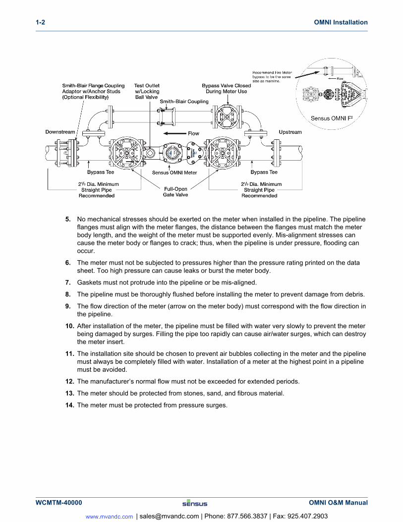
1. When installing Sensus OMNI Meter with the strainer, a minimum of 2-½ pipe diameters of straight run of pipe or equivalent full open components is required upstream and downstream of the meter or strainer flanges. Full open flow components may consist of: straight pipe, full open gate valves, bypass tees and concentric reducers (1 nominal pipe size reduction only).
2. Gate valves located immediately upstream or downstream are acceptable, provided they are fully open during meter service and are not used to throttle flow rates through the meter.
3. Install non-concentric reducers, check valves, back flow preventers, PRV (pressure reducing valves), throttling devices, altitude valves no closer than 4 pipe diameters downstream of the meter. Always avoid placing any of these devices upstream of any meter since the placement will put the meter in a low pressure zone thus possibly causing inconsistent accuracy and reduced longevity.
4. Accuracy levels may be determined by comparison accuracy testing either by using a Sensus Portable Large Meter Tester, by removing the suspect meter and testing it on a calibrated test bench or returning the suspect measuring chamber or complete meter to Sensus Metering for a certified accuracy test.
OMNI meters can be installed vertically or rotated on the bolt pattern in any orientation. Contact Sensus with any questions.
High flow meter applications or near air discharge must maintain a minimum of 15 psi (1 bar) downstream pressure to assure accuracy and meter longevity.
OMNI O&M Manual WCMTM-40000
| [email protected] | Phone: 877.566.3837 | Fax: 925.407.2903
1-2 OMNI Installation
5. No mechanical stresses should be exerted on the meter when installed in the pipeline. The pipeline flanges must align with the meter flanges, the distance between the flanges must match the meter body length, and the weight of the meter must be supported evenly. Mis-alignment stresses can cause the meter body or flanges to crack; thus, when the pipeline is under pressure, flooding can occur.
6. The meter must not be subjected to pressures higher than the pressure rating printed on the data sheet. Too high pressure can cause leaks or burst the meter body.
7. Gaskets must not protrude into the pipeline or be mis-aligned.
8. The pipeline must be thoroughly flushed before installing the meter to prevent damage from debris.
9. The flow direction of the meter (arrow on the meter body) must correspond with the flow direction in the pipeline.
10. After installation of the meter, the pipeline must be filled with water very slowly to prevent the meter being damaged by surges. Filling the pipe too rapidly can cause air/water surges, which can destroy the meter insert.
11. The installation site should be chosen to prevent air bubbles collecting in the meter and the pipeline must always be completely filled with water. Installation of a meter at the highest point in a pipeline must be avoided.
12. The manufacturer’s normal flow must not be exceeded for extended periods.
13. The meter should be protected from stones, sand, and fibrous material.
14. The meter must be protected from pressure surges.
WCMTM-40000 OMNI O&M Manual
| [email protected] | Phone: 877.566.3837 | Fax: 925.407.2903
Signal Connections 2-1
2 Signal Connections
2.1 Description
The OMNI register utilizes fully solid-state electronics, and outputs a programmable (using Sensus Unipro and OMNI communicator) digital pulse signal suited for interfacing with ACT-PAK instruments to achieve a 4 to 20
mA output and SCADA systems. The OMNI register is compatible only with OMNI style meters (T2, C2, and
F2).
2.2 Features
The OMNI register features programmable totalizer registration, digital pulse signal, AMR reading digits, and a resettable test totalizer. Because the register is hermetically sealed, it is safe for pit environments as well as above ground settings. The tamper-proof security cover can be positioned in any of 270 degrees of rotation, with indexing points at each of the 90-degree customary register viewing positions.
2.3 Application
The OMNI register is used where critically accurate totalization of water is imperative. The OMNI register is designed for non-explosive atmosphere and can be used in both above ground and pit settings. In pit settings, submersion should be in no more than four feet of water depth.
2.4 Electrical Connections
The OMNI register is standard with both AMR and pulse output wires. The pulse wire is 25 feet long; the AMR wire with touch button is 20 feet long. Splicing of these wires or connecting to these wires should be performed in accordance with standard practices depending on the environment of the application. Care must always be taken when connections are made for meters in high humidity/flooded pit settings. Maximum pulse cable length should be 1000 feet without a repeater.
The OMNI register can be configured in four arrangements, shown in Figures 2-1 through 2-4 below.
OMNI O&M Manual WCMTM-40000
| [email protected] | Phone: 877.566.3837 | Fax: 925.407.2903
2-2 Signal Connections
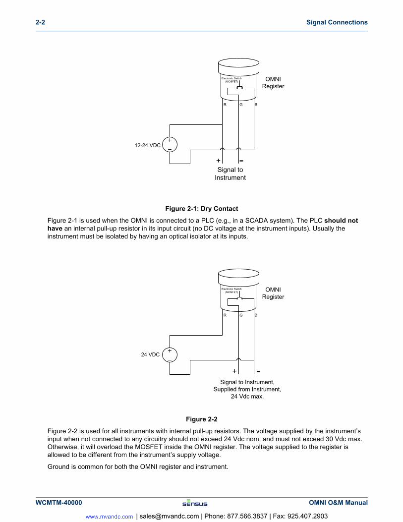
Figure 2-1: Dry Contact
Figure 2-1 is used when the OMNI is connected to a PLC (e.g., in a SCADA system). The PLC should not have an internal pull-up resistor in its input circuit (no DC voltage at the instrument inputs). Usually the instrument must be isolated by having an optical isolator at its inputs.
Figure 2-2
Figure 2-2 is used for all instruments with internal pull-up resistors. The voltage supplied by the instrument’s input when not connected to any circuitry should not exceed 24 Vdc nom. and must not exceed 30 Vdc max. Otherwise, it will overload the MOSFET inside the OMNI register. The voltage supplied to the register is allowed to be different from the instrument’s supply voltage.
Ground is common for both the OMNI register and instrument.
12-24 VDC
R G B
Electronic Switch(MOSFET) OMNI
Register
+Signal to
Instrument
24 VDC
R G B
Electronic Switch(MOSFET) OMNI
Register
+Signal to Instrument,
Supplied from Instrument,24 Vdc max.
WCMTM-40000 OMNI O&M Manual
| [email protected] | Phone: 877.566.3837 | Fax: 925.407.2903
Signal Connections 2-3
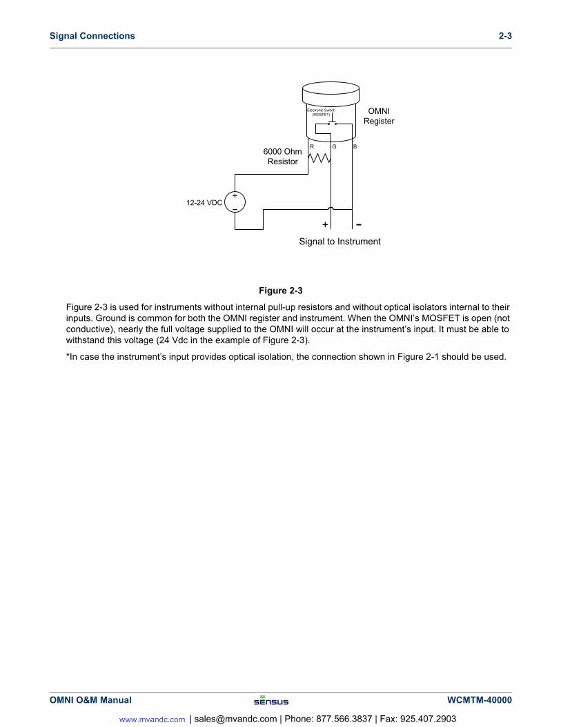
Figure 2-3
Figure 2-3 is used for instruments without internal pull-up resistors and without optical isolators internal to their inputs. Ground is common for both the OMNI register and instrument. When the OMNI’s MOSFET is open (not conductive), nearly the full voltage supplied to the OMNI will occur at the instrument’s input. It must be able to withstand this voltage (24 Vdc in the example of Figure 2-3).
*In case the instrument’s input provides optical isolation, the connection shown in Figure 2-1 should be used.
12-24 VDC
R G B
Electronic Switch(MOSFET) OMNI
Register
+Signal to Instrument
6000 OhmResistor
OMNI O&M Manual WCMTM-40000
| [email protected] | Phone: 877.566.3837 | Fax: 925.407.2903
2-4 Signal Connections
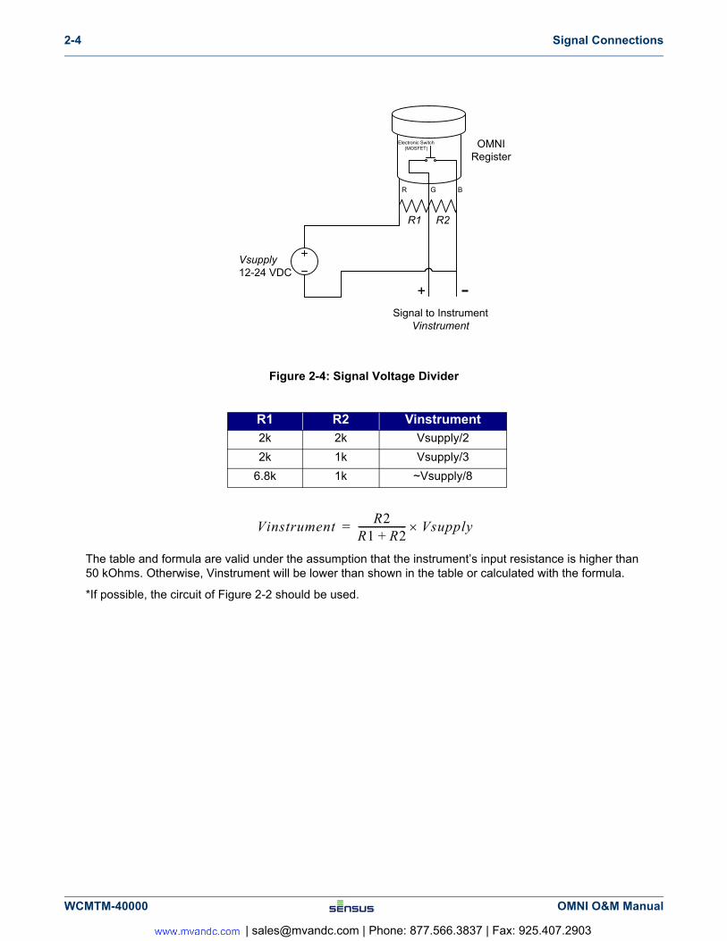
Figure 2-4: Signal Voltage Divider
The table and formula are valid under the assumption that the instrument’s input resistance is higher than 50 kOhms. Otherwise, Vinstrument will be lower than shown in the table or calculated with the formula.
*If possible, the circuit of Figure 2-2 should be used.
R1 R2 Vinstrument2k 2k Vsupply/2
2k 1k Vsupply/3
6.8k 1k ~Vsupply/8
Vsupply12-24 VDC
R G B
Electronic Switch(MOSFET) OMNI
Register
+Signal to Instrument
Vinstrument
R1 R2
VinstrumentR2
R1 R2+-------------------- Vsupply=
WCMTM-40000 OMNI O&M Manual
| [email protected] | Phone: 877.566.3837 | Fax: 925.407.2903
Measuring Chamber Removal and Disassembly 3-1
3 Measuring Chamber Removal and Disassembly
3.1 Tools Required
• 2.5 and 3 mm hex head ball end drivers
• Sensus seal screw tool
• 7/16” x 1/2” open end wrench
• 9/16” x 5/8” open end wrench
• 3/4” x 11/16” open end wrench (required wrench sizes are determined by size and type of OMNI meter)
• Assembly grease
If the meter is under pressure, pressure must be turned off and relieved before chamber bolts are loosened or removed!!
OMNI O&M Manual WCMTM-40000
| [email protected] | Phone: 877.566.3837 | Fax: 925.407.2903
3-2 Measuring Chamber Removal and Disassembly
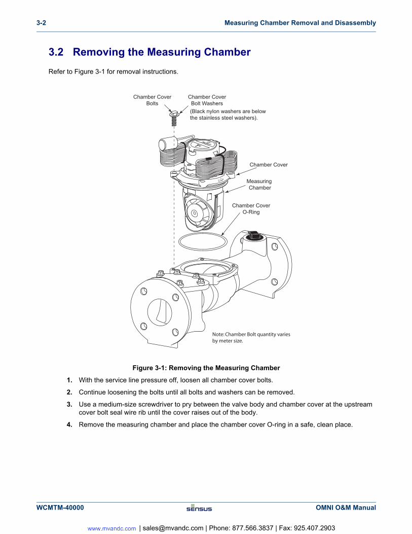
3.2 Removing the Measuring Chamber
Refer to Figure 3-1 for removal instructions.
Figure 3-1: Removing the Measuring Chamber
1. With the service line pressure off, loosen all chamber cover bolts.
2. Continue loosening the bolts until all bolts and washers can be removed.
3. Use a medium-size screwdriver to pry between the valve body and chamber cover at the upstream cover bolt seal wire rib until the cover raises out of the body.
4. Remove the measuring chamber and place the chamber cover O-ring in a safe, clean place.
Chamber CoverBolts
Chamber CoverBolt Washers
Chamber CoverO-Ring
Chamber Cover
Measuring Chamber
Note: Chamber Bolt quantity varies by meter size.
(Black nylon washers are below the stainless steel washers).
WCMTM-40000 OMNI O&M Manual
| [email protected] | Phone: 877.566.3837 | Fax: 925.407.2903
Measuring Chamber Removal and Disassembly 3-3
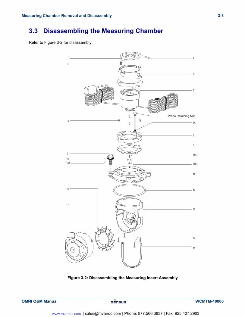
3.3 Disassembling the Measuring Chamber
Refer to Figure 3-2 for disassembly.
Figure 3-2: Disassembling the Measuring Insert Assembly
Probe Retaining Nut
OMNI O&M Manual WCMTM-40000
| [email protected] | Phone: 877.566.3837 | Fax: 925.407.2903
3-4 Measuring Chamber Removal and Disassembly
1. Remove the bonnet seal screw (4) using the Sensus seal removal tool.
2. Twist the bonnet (3) counter-clockwise and lift it off the base.
3. Raise the register (5) off the base, taking care to not strain the pick-up probe wire.
4. Using your fingers (or a 7/16” wrench, if required), remove the probe retaining nut and remove the register and probe assembly from the measuring insert. (13).
5. Place the register assembly in a safe place.
6. Remove the bonnet retaining ring (7) by removing the four allen head countersink screws (6).
7. Remove the four allen head screws (14) from the measuring insert (13).
8. Pull the measuring insert (13) away from the chamber cover (11).
9. Twist the inlet flow straightener balance plate (17) counter-clockwise, then pull it straight out of the measuring insert housing.
10. Remove the rotor (16) from the measuring insert by slowly pulling it out of the housing.
11. Inspect and replace any damaged parts.
12. For re-assembly, reverse this procedure.
3.4 Exchanging the Measuring Insert
• Before the installation of a replacement measuring insert, the inside surface of the body, especially the seating areas of the O-ring, must be checked for damage. If damaged, a new O-ring must be used.
• The O-ring and the lip seal must be lubricated with grease approved for use with potable water before installation in to the meter body.
• To avoid damaging the O-ring when installing a meter insert, the O-ring must first be fitted onto the cover flange and then pushed into the meter body. If the O-ring is fitted into the body first, it can be pinched when fitting the meter inset and cause leaks.
• When installing the measuring insert into the meter body, make sure that the direction of the arrow on the head flange aligns with the arrow on the meter body.
• The screws fixing the measuring insert in the body shall be screwed hand tight and then tightened crosswise with the correct-sized tool.
If the pipe pressure is not yet relieved, water will spray out when the retaining nut is two turns from complete removal.
Take care to slowly separate the two housings or the rotor will fall out of the measuring insert and will be damaged.
Do not remove the chamber seal gasket (11). It is factory glued in place for ease of chamber installation. If a replacement gasket is required, you must use a waterproof glue to attach it to the chamber.
WCMTM-40000 OMNI O&M Manual
| [email protected] | Phone: 877.566.3837 | Fax: 925.407.2903
Specifications A-1
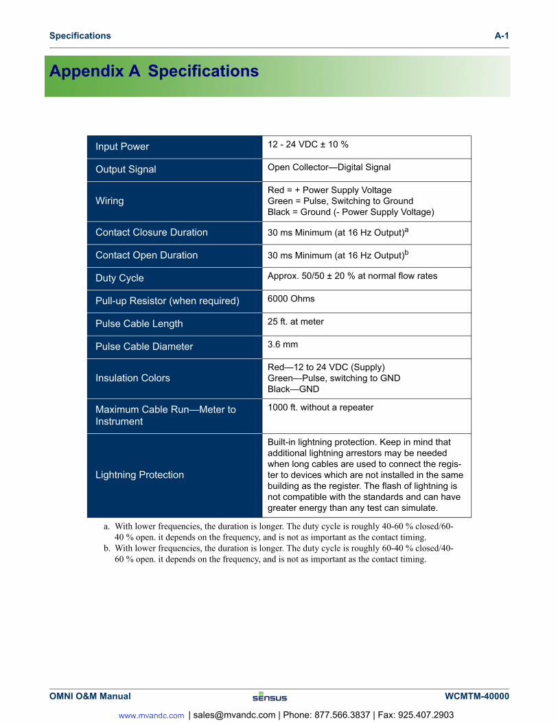
Appendix A Specifications
Input Power 12 - 24 VDC ± 10 %
Output Signal Open Collector—Digital Signal
WiringRed = + Power Supply VoltageGreen = Pulse, Switching to GroundBlack = Ground (- Power Supply Voltage)
Contact Closure Duration 30 ms Minimum (at 16 Hz Output)a
a. With lower frequencies, the duration is longer. The duty cycle is roughly 40-60 % closed/60-40 % open. it depends on the frequency, and is not as important as the contact timing.
Contact Open Duration 30 ms Minimum (at 16 Hz Output)b
b. With lower frequencies, the duration is longer. The duty cycle is roughly 60-40 % closed/40-60 % open. it depends on the frequency, and is not as important as the contact timing.
Duty Cycle Approx. 50/50 ± 20 % at normal flow rates
Pull-up Resistor (when required) 6000 Ohms
Pulse Cable Length 25 ft. at meter
Pulse Cable Diameter 3.6 mm
Insulation ColorsRed—12 to 24 VDC (Supply)Green—Pulse, switching to GNDBlack—GND
Maximum Cable Run—Meter to Instrument
1000 ft. without a repeater
Lightning Protection
Built-in lightning protection. Keep in mind that additional lightning arrestors may be needed when long cables are used to connect the regis-ter to devices which are not installed in the same building as the register. The flash of lightning is not compatible with the standards and can have greater energy than any test can simulate.
OMNI O&M Manual WCMTM-40000
| [email protected] | Phone: 877.566.3837 | Fax: 925.407.2903
OMNI T2 and C2 Parts List B-1
Appendix B OMNI T2 and C2 Parts List
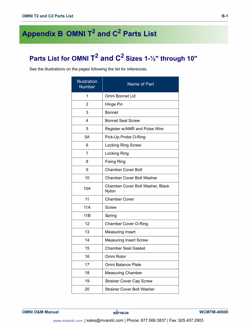
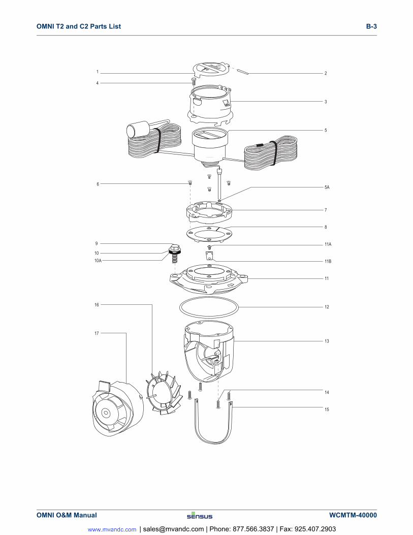
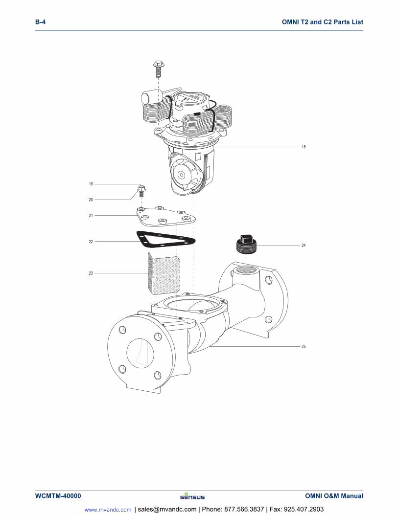
Parts List for OMNI T2 and C2 Sizes 1-½" through 10"
See the illustrations on the pages following the list for references.
Illustration Number
Name of Part
1 Omni Bonnet Lid
2 Hinge Pin
3 Bonnet
4 Bonnet Seal Screw
5 Register w/AMR and Pulse Wire
5A Pick-Up Probe O-Ring
6 Locking Ring Screw
7 Locking Ring
8 Fixing Ring
9 Chamber Cover Bolt
10 Chamber Cover Bolt Washer
10AChamber Cover Bolt Washer, Black Nylon
11 Chamber Cover
11A Screw
11B Spring
12 Chamber Cover O-Ring
13 Measuring Insert
14 Measuring Insert Screw
15 Chamber Seal Gasket
16 Omni Rotor
17 Omni Balance Plate
18 Measuring Chamber
19 Strainer Cover Cap Screw
20 Strainer Cover Bolt Washer
OMNI O&M Manual WCMTM-40000
| [email protected] | Phone: 877.566.3837 | Fax: 925.407.2903
B-2 OMNI T2 and C2 Parts List
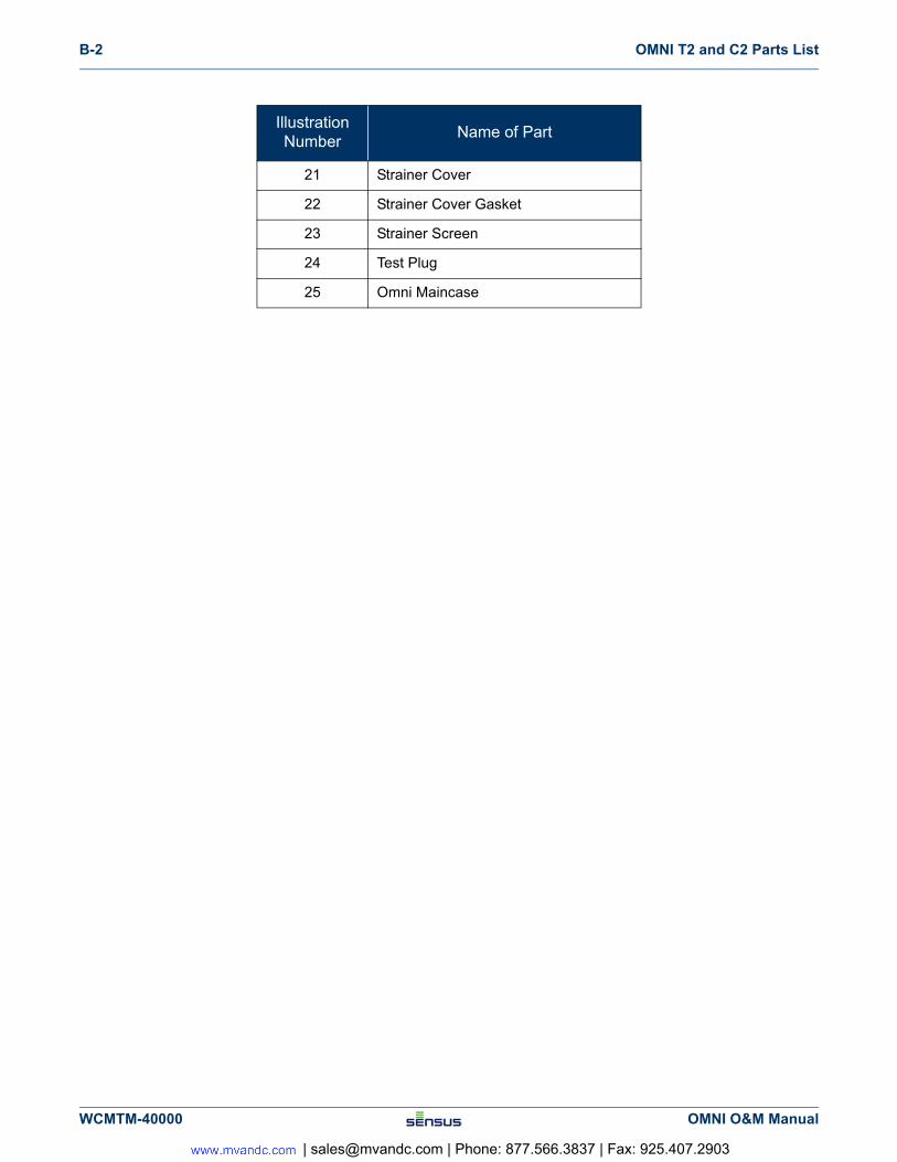
21 Strainer Cover
22 Strainer Cover Gasket
23 Strainer Screen
24 Test Plug
25 Omni Maincase
Illustration Number
Name of Part
WCMTM-40000 OMNI O&M Manual
| [email protected] | Phone: 877.566.3837 | Fax: 925.407.2903
OMNI T2 and C2 Parts List B-3
OMNI O&M Manual WCMTM-40000
| [email protected] | Phone: 877.566.3837 | Fax: 925.407.2903
B-4 OMNI T2 and C2 Parts List
WCMTM-40000 OMNI O&M Manual
| [email protected] | Phone: 877.566.3837 | Fax: 925.407.2903
Top Related