


Languages
Pages
Legal


VCSFlagy/n
StreamingFlagy/n
PacketsFlagy/n
Contents of this field are based upon the value in the VCS_Flag field:
This field is only present when the VCS_Flag=y:
VCS_Counter
• Only present when Streaming_Flag=y• Contents based on value in Packet Flag
InfoField
1bit
1bit
1bit
1 Bit 4 Bits5 Bits
8 Bits (optional)
16 Bits (optional)
RemainderOf VCDF
Virtual Channel Data Field
VCS Flag Value Contents
Yes (1) VCS_ID
No (0) Spare bits
Packet Flag Contents
Yes (1) !st Header Pointer
No (0) Number of Valid Octets
Transfer Frame Structures
Notes: 1) A VC is managed to either contain VC Sub-channels or not 2) Streaming refers to Packets that cross frame boundaries or VCA user octets that need not fill the Information area 3)VCS ID is the identifier field for the VC Sub-channel4) VCA SDUs carry user specified Octets5) VCDF SDU is the contents of a frame’s data field6) VCS Counter provides continuity check for VC Sub-channel

Rationale for Specific Field Placement In Frame Structure1. If included, Insert Zone must be included in all frames of a Master Channel. Can not be encrypted because MC
processing precedes Decryption.• Insert Zone should contain a size field to allow MC Insert Zone Service to operate without setup by Service
Management.2. If Flagged the Secondary header must follow the Insert Zone ( could be prior to or after Security Header)3. The Transfer Frame Data Field is place in a position that VC constructer can insert the VCSub-channel (the Data Field)
directly into the frame without effecting the VC channel processes.
Rationale for Specific Field Placement In Frame Header1. The three flags (FEC, Insert Zone and Secondary Header) are included within first byte of header to fill out the byte.
• The order of appearance of the flags could be changed2. VC ID and SCID Use Fields fill a byte. SCID Use Field is place as the second field in the byte so that it appears just
before the SCID Field.3. The SCID and VC Count Size Fields share a two byte grouping. The placement of the VC Count Size Field follows the
SCID so that it appears just before the VC Count Field.4. The VC Count Field can be zero to seven bytes as identified by the contents of the VC Count Size Field.
Rationale for Specific Field Placement In Frame Data Field Header1. The first byte provides the structural information (bits 0 to 3) and VC Sub-Cannel Identification (bits 4 through 7)2. The VCS Counter field is required only when the Field contains a VC sub-channel.3. The next field is required only if streaming data is flagged. This field is either a first header pointer for packets or a
count of valid octets for VCA Data.

Transfer Frame Header Structural Components
• Version ID- is extended to 4bits to accommodate 3 additional frame versions after this one (1100) is codified
• Destination/Source - Identifies the Spacecraft ID as either the source of the data or the intended recipient
• FEC Included -- signals the inclusion of the CRC (y/n)
• Signals the receiving Master Channel process to check Frame’s validity using attached FECF
• Master Channel Insert Zone contained Flag
• Virtual Channel Secondary Header contained Flag
• Frame Length –(N+1) allows for frame to be as large as 65536 octets
• Virtual Channel ID – accommodates 64 Virtual Channels
• Spacecraft ID use Field can be used by a Mission to organize its data without requiring multiple SCIDs
• Spacecraft ID - allows for 8192 names
• VC Count Size – the contents identify the size of the VC count field– (size can be 0 to 7 octets)
• VC Count –VC counter that has a minimum size of 0 octet and a maximum size of 7 octets;• This counter will need to increment when sequence control is specified for this VC• The content of this field can be user defined when sequence control is not specified for this VC• This field can be used by the crypto authentication process eliminating the need of a second counter
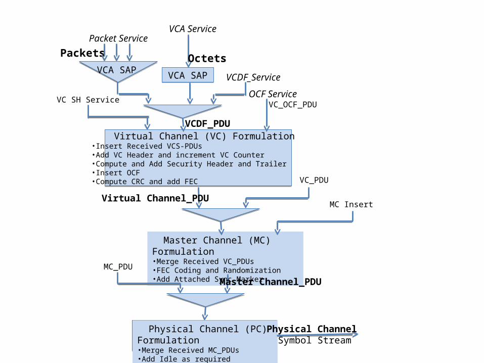
PacketsPacket Service
VCA Service
Octets
OCF ServiceVC_OCF_PDU
Virtual Channel (VC) Formulation•Insert Received VCS-PDUs •Add VC Header and increment VC Counter•Compute and Add Security Header and Trailer•Insert OCF•Compute CRC and add FEC
Master Channel (MC) Formulation•Merge Received VC_PDUs •FEC Coding and Randomization•Add Attached Sync Marker
VCDF_PDU
Virtual Channel_PDU
VCA SAPVCA SAP VCDF_Service
VC_PDU
Master Channel_PDU
MC_PDU
Physical Channel (PC) Formulation•Merge Received MC_PDUs •Add Idle as required
Physical Channel Symbol Stream
VCA SAP
MC Insert
VC SH Service

TransferFrame
PrimaryHeader
TransferFrame
SecurityHeader
Transfer Frame Data Field(VCF_SDU)
Transfer
FrameSecurityTrailer
TransferFrame
OperationalControl Field
TransferFrame
Error ControlField
VC Transfer Frame
6-10 Octets 4 Octets VariableVariableVariable VariableMandatory Optional Optional OptionalOptional Optional
VC Data Field
Received from SAPand inserted into frame
Received from OC Service and
Inserted into frameCalculated and
entered into frame
Computed and entered in frame
Generated and entered into frame 11
44
3322 55
Note: The number within the circles identifies the order of inclusion in the frame formation process
Transfer Frame Assembly
MasterChannel
InsertZone
“fixed”
Optional
VirtualChannel
SecondaryHeader
Variable
Optional

PacketsPacket Service VCA Service
Octets
OCF Service
Virtual Channel (VC) Formulation•Add VC Header and increment VC Counter•Insert Received VC-SDUs •Insert OCF•Compute and Add Security Header and Trailer•Compute and add CRC (optional)
Master Channel (MC) Formulation•Merge Received VC_PDUs •FEC Coding and Randomization•Add Attached Sync Marker
VCDF_SDU (VC_Frame Data Field)
Virtual_Channel_Frame
VCDF_Service
VC_Frame
Master_Channel_Frame
MC_Frame
Physical Channel (PC) Formulation•Merge Received MC_PDUs •Add Idle as required
Physical Channel Symbol Stream
VCS SAP
Data Sub-layer
Input Sub-layer
Link_Transmission_Unit
Physical Layer
Sync& Coding Sub-layer
PacketsPacket Service
VCA Service
Octets
VC_OCF_SDU
• Deliver Received verified VC-Frames • Check VC Continuity• Perform Security Process • Extract OCF
• Delimit Frames using Sync Marker• FEC Decoding and Derandomization• Validate Frame using CRC when contained• Separate MC_Frames
VCS_SDU
Virtual_Channel_Frame
VCDF_Service
Master_Channel_Frame
Physical Channel (PC) Reception•Acquire symbols
Physical Channel Symbol Stream
VCS SAP
Data Sub-layer
Output Sub-layer
Link Transmission_Unit (ASM+VC_Frame)
Physical Layer
Sync& Coding Sub-layer
Transmitting (sending) Side Receiving Side
VC Service
MCF ServiceMC_Frame
VC_Frame
Separate VC_Frames
Separate VC_Frames
Separate GVCS_Frames Select VCF_SDU
Merge VC Frames
Merge MC Frames
Form VCF_SDUForm VCF_SDU VCA SAP
VCA SAPExtract Octets Extract Packets
VC SH Service
MC Insert

Packet SAP VC_OCFService
Data Unit
VCA_SDUs
VCF_SDUsOCF_SDUs
Virtual Channel
Processing
Virtual Channel Creation
Virtual Channel Data Unit (VCDU)
Master Channel Process (Virtual Channel Multiplexing)
Master Channel Data Unit (MCDU)
All Channel Multiplexing
Physical Channel
Coding and Sync Sub-Layer
Packets
PacketProcessingFunction
VCAProcessingFunction
VirtualChannel
Processing
VirtualChannel
Processing
Master ChannelProcess
VCA-SAP
OptionalProcess
Multiplexer
ReplicatedProcesses
Process
Legend
Security Process
CRC Creation
OCF
-SAP
Note: -Packet SAP can support multiple users-VCA SAP can only support a single user
VCDF-SAP
VCDF_SDUs
VCF-SDU = VC Data Field

VCA_SDUs
VCDF_SDUs VCDF_SDUs
Virtual Channel
Processing
Virtual Channel SDU Extraction
Virtual ChannelData Unit (VCDU)
Master Channel Process (Virtual Channel Multiplexing)
Master Channel Data Unit (MCDU)
All Channel Multiplexing
Physical Channel
Coding and Sync Sub-Layer
Packets
PacketProcessingFunction
VCAProcessingFunction
VirtualChannel
Processing
VirtualChannel
Processing
Master ChannelProcess
OptionalProcess
Multiplexer
ReplicatedProcesses
Process
Legend
Security Process
CRC Validation
Packet SAP VCA-SAP
Note: -Security Process may output a report-CRC Validation will output a report to OCF
VCDF-SDUs
VCDF-SAP
VC-SDUs
VC-SAPCOP-1Service
OCF_SDUs
OCF-SAPCRC Report

Managed ParametersMaster Channel---
• FEC Code, • Inter-frame Idle Allowed/not allowed? • Fixed/variable frame length?• VC priorities• Max Frame Size allowed • ASM, • Fill type (frame or bits)
VC --- • Count size• Sequence controlled y/n? • Sequence count indexing required• OCF y/n• Security header & trailer sizes• Security SA (use VC Count?)• VCS/packets/VCA (signaled in frame)• VCS --- list allowed data types • Streaming data (Packets not required to fit within a single frame)
VCS ---• Packets/VCA (signaled in frame)• Size of Field


Short Uplink Code Performance
12

LDPCRate ½ Block size 16 384 bitsRate ½ Block size 1024 1/2, 1024 LDPC with BCH TEDLDPC Rate 4/5 Block size 16384
GSFC-LDPC (8176,7156)
BCH SEC TED
Overall Coding Performance (provided by JPL Coding Group)

TransferFrame
PrimaryHeader
TransferFrame
SecurityHeader
Transfer Frame Data Field
(VCDF_PDU)
TransferFrame
SecurityTrailer
TransferFrame
OperationalControl Field
TransferFrame
Error ControlField
Transfer Frame
6-11 Octets 4 Octets VariableVariableVariable VariableMandatory Optional Optional OptionalOptional Optional
MasterChannel
Insert Zone
Variable
Optional
VirtualChannel
SecondaryHeader
Variable
Optional
VersionID
Destinationor
SourceID
SpacecraftID
Transfer Frame Header
4 bits 1 Bit1 bit 13 bits
VCCount
size
VCCount
6 Bits
Virtual Channel
ID
0-56 Bits3 Bits2 Bits
FECIncluded
Flag
Frame Length
16 Bits
SCIDUseField
InsertZoneFlag
SecondaryHeader
Flag
1 Bit1 Bit
VCSFlagy/n
StreamingFlagy/n
PacketsFlagy/n
Contents of this field are based upon the value in the VCS_Flag field:
This field is only present when the VCS_Flag=y:
VCS_Counter
• Only present when Streaming_Flag=y• Contents based on value in Packet Flag
InfoField
1bit
1bit
1bit
1 Bit 4 Bits5 Bits
8 Bits (optional)
16 Bits (optional)
RemainderOf VCDF
VCS Flag Value Contents
Yes (1) VCS_ID
No (0) Spare bits
Packet Flag Contents
Yes (1) !st Header Pointer
No (0) Number of Valid Octets
Virtual Channel Data Field
Top Related