


Languages
Pages
Legal

VARIABLE-SPEED SWITCHED RELUCTANCE MOTOR
DRIVES FOR LOW-COST, HIGH-VOLUME APPLICATIONS
By
Jae Hyuck Kim
Dissertation submitted to the faculty of the Virginia Polytechnic Institute and State
University in partial fulfillment of the requirements for the degree of
Doctor of Philosophy
In
Electrical Engineering
Krishnan Ramu, Committee Chair
Jamie De La Reelopez
Douglas K. Lindner
Daniel J. Stilwell
Werner E. Kohler
March 3, 2010
Blacksburg, Virginia
Keywords: Switched reluctance motor, power converter, variable-speed drives,
Low-cost, high-volume applications, sensorless control, optimal efficiency
Abstract
Variable-Speed Switched Reluctance Motor Drives for
Low-Cost, High-Volume Applications
Jae Hyuck Kim
Demand for energy-saving variable speed drives in low-cost, high-volume appliances has
increased due to energy and environmental concerns and hence the need to comply with new
regulations. Switched reluctance motor (SRMs) have been considered by many as attractive
alternatives for brush commutated motors or permanent magnet brushless dc motors
(PMBDCMs) in such cost-sensitive applications. The SRMs’ unique features such as simple and
fault-tolerant structure and unidirectional flow of their phase currents endow them with the
possibility of various configurations on both machine and converter topologies for different
applications. In the present study, three different variable-speed motor drive systems are
proposed, studied, and implemented for their deployment in low-cost, high-volume applications
with the power rating of 1.5kW or less. Two different two-phase SRMs and three different power
converters are employed to realize three different low-cost drive systems. The first drive system
is realized using a novel converter requiring only a single-controllable switch and an asymmetric
two-phase 8/4 SRM capable of self-starting and four-quadrant operation. The second drive
system is realized using another novel converter requiring two controllable switches, that way to
achieve better control and utilization of the asymmetric 8/4 motor. The target applications for
both drive systems are low power, low performance drives such as fans, hand tools, small
appliances, etc. The third system is realized using a high-speed two-phase 4/2 SRM and a split ac
source converter, which is designed for high-speed applications such as vacuum cleaners,
ultracentrifuges, etc. The control and design aspects for each drive system are studied. Selection
of optimal firing angles and optimal number of winding turns are also investigated. All of the
drive systems are first demonstrated on the position sensor-based speed-control scheme. To

make the drive system even more cost-competitive, operation without the position sensor using
the novel parameter insensitive sensorless control scheme is proposed and implemented. Concept,
analysis, simulation, and experimental verification of the proposed sensorless scheme are
discussed in detail.

iv
Acknowledgements
First and foremost, I would like to express my sincere gratitude to my advisor, Professor
Krishnan Ramu for his invaluable encouragement and guidance throughout the course of this
research. He has given me the opportunity to instill in me the fundamentals of electric machines
and drives that will continue to keep me firmly grounded in my future endeavors.
I would also like to thank my committee members, Dr. Jamie De La Reelopez, Dr.
Douglas K. Lindner, Dr. Daniel J. Stilwell, and Dr. Werber E. Kohler for their encouragement
and concerns.
Additional special thanks go to my colleagues: Cheewoo Lee for his camaraderie and
encouragement whenever I have needed it and Ethan Swint and Nimal Lobo for their
proofreading and technical discussions.
Last but not least, I wish to express everlasting thanks to my parents, parents-in-law and
the rest of my family for their wholehearted love and support. Without them, I would not ever
made it this far. The most crucial support came from my wife, best friend, and partner, Jeongwoo.
Your patience, love, and strength helped me complete this journey. Thank you.

v
Table of Contents
Abstract ii
Acknowledgements iv
Table of Contents v
List of Figures ix
List of Tables xiv
Chapter 1
Introduction
1.1. Motivation 1
1.2. Scope and Contributions 7
1.3. Outlines of Dissertation 8
Chapter 2
SRM Fundamentals and State-of-Art-Review of SRM Converters
2.1 SRM Fundamentals 10
2.1.1 Principles of Operation 10
2.1.2 Mathematical Model of SRM 12
2.1.3 Control of SRM 16
2.2 State-of-Art-Review of SRM Converters 18
2.2.1 Classification Based on the Number of Controllable Switches 19
2.2.1.1 Two-switch-per-Phase Converters 20
2.2.1.2 N+1 Switch-Per-Phase Converters 21
2.2.1.3 Single-Switch-Per-Phase Converters 23
2.2.2 Classification Based on the Energy Recovery 25
2.2.2.1 Energy Dissipative Converters 25
2.2.2.2 Energy Recovery (Regeneration) Converters 26

vi
Chapter 3
Proposed Drive System 1: Single-Controllable-Switch-Based SRM Drive
3.1 Introduction 31
3.2 Proposed Drive System 33
3.2.1 Asymmetric 8/4 SRM Configuration 33
3.2.2 Asymmetric 8/4 SRM Model Characterizations 36
3.2.3 Power Converter 41
3.3 Derivation of Drive System Equations 42
3.4 Converter Modes of Operation 44
3.5 Performance Constraints and Design Consideration 47
3.5.1 Commutation of Main and Auxiliary Phase Currents 47
3.5.2 Design Consideration for Optimal Commutation 49
3.6 Comparison of the Proposed Converter With Other Converter 56
3.7 Drive System Control 57
3.7.1 Self-Starting 57
3.7.2 Four-quadrant operation 57
3.7.3 Position Sensorless Operation 58
3.8 Dynamic Simulation 58
3.9 Experimental Verification 59
3.10 Summary 64
Chapter 4
Proposed Drive System 2: Two-Controllable-Switch-Based SRM Drive
4.1 Introduction 65
4.2 Proposed Drive System 66
4.2.1 Machine 66
4.2.2 Power Converter 67
4.3 Derivation of System Equations and Principle of Operation 68
4.4 Steady-State Analysis 73
4.4.1 Estimation of Capacitor C2 Voltage 73
4.4.2 Power Transfer Between C1 and C2 77

vii
4.5 Design Consideration 80
4.6 Drive Control and Operation 82
4.6.1 Starting 82
4.6.2 Drive System Control 83
4.7 Simulation Verification 85
4.8 Experimental Results 87
4.9 Summary 89
Chapter 5
Proposed Drive System 3: Two-Controllable-Switch-Based SRM Drive for High-Speed
Applications
5.1. Introduction 91
5.2. Proposed Drive System 93
5.2.1. Machine 93
5.2.2. Power Converter 94
5.3. Modeling and Derivation of Drive System Equations 95
5.4. Converter Modes of Operation 99
5.5. Optimal Efficiency Control of SRM Drives in Single-Pulse Operation 102
5.5.1. Switching Angle Control 102
5.5.2. Conventional Switching Angle Control 103
5.5.3. Proposed Angle Control Scheme Based on Characterization of 105
Optimal Switching Angles in Single-Pulse Operation
5.6. Drive System Controller 109
5.7. Selection of Optimal Number of Winding Turns 111
5.8. Simulation Verification 114
5.9. Experimental Results 116
5.9.1. Construction of Prototype Drive System 116
5.9.2. Static Tests 118
5.9.3. Dynamic Tests 120
5.10. Summary 122

viii
Chapter 6
Position Sensorless Operation of the SRM Drives
6.1. Introduction 123
6.2. State-of-the-Art-Review 124
6.3. Proposed Sensorless Control Algorithm 125
6.3.1. Principle of Estimation 126
6.3.2. Digital Real-time Implementation 130
6.4. Sensorless Drive System Control 132
6.4.1. Sensorless Starting 132
6.4.2. Hysteresis Current Control 132
6.4.3. Main Control Algorithm 133
6.4.4. Firing Angle Control 137
6.5. Simulation Verification 139
6.6. Experimental Results 140
6.7. Summary 143
Chapter 7
Conclusions 145
Bibliography 147
ix
List of Figures
Fig. 1.1. Conventional variable-speed ac drive with six-switch-based inverter 2
Fig. 1.2. Universal motor drives 2
Fig. 1.3. Permanent split capacitor (PSC) single-phase induction motor using two controllable 3
switches
Fig. 1.4. Two-phase induction motor drive using four controllable switches 4
Fig. 1.5 Asymmetric three-phase induction motor drive using three-controllable switches 4
Fig. 1.6. Permanent magnet dc motor using three controllable switches 5
Fig. 1.7. Two-phase SRM drive with asymmetric converter 6
Fig. 2.1. Three-phase 6/4 SRM 11
Fig. 2.2. Idealized waveforms of a phase of the three-phase 6/4 SRM 12
Fig. 2.3. Block diagram representation of dynamic mathematical model of an n-phase SRM 15
Fig. 2.4. Cascaded control block diagram for an SRM drive 16
Fig. 2.5. SRM torque-speed characteristics 17
Fig. 2.6. Classification of the SRM converters based on the number of the controllable 20
switches
Fig. 2.7. Asymmetric bridge converter 21
Fig. 2.8. Shared switch N+1 converter for two-phase SRM 22
Fig. 2.9. Dual decay converter 22
Fig. 2.10. Suppression resistor (R-dump) converters 23
Fig.2.11. Bifilar converter 24
Fig.2.12. Split dc supply converter for two-phase SRM 25
Fig.2.13. Classification of the SRM converters based on energy recovery 26
Fig. 2.14. C-dump converters with the stored energy circulated to dc link (class I) 28
Fig.2.15. C-dump converters with the auxiliary inductor replaced by the phase winding 29
(class II)
Fig. 2.16. Variable dc link front-end buck converter 30
Fig. 2.17. Variable dc link front-end buckboost converter 30
x
Fig. 3.1. Original single-controllable-switch converter 32
Fig. 3.2. New single-controllable-switch converter 32
Fig. 3.3. Asymmetric 8/4 SRM 35
Fig. 3.4. Magnetization characteristics for the asymmetric two-phase SRM obtained from 37
two-dimensional finite element analysis (FEA) simulation
Fig. 3.5. Inductance for the two-phase 444 SRM obtained from two-dimensional finite 38
element analysis (FEA) simulation
Fig. 3.6. Torque for the two-phase 444 SRM obtained from two-dimensional finite element 39
analysis (FEA) simulation
Fig. 3.7. Flux lines for main and auxiliary phase at aligned positions 40
Fig. 3.8. Converter modes of operation 45
Fig. 3.9. Main and auxiliary current waveforms in PWM chopping mode 48
Fig. 3.10. Desired waveforms for the current commutation within a stroke cycle in 48
single-pulse mode.
Fig. 3.11. Commutation time vs. capacitance vs. inductance 53
Fig. 3.12. Voltages ripple vs. capacitance vs. inductance 53
Fig. 3.13. Main and auxiliary winding currents for different sizes of capacitor Cr 54
Fig. 3.14. Voltages across the main winding, auxiliary winding, and the capacitor Cr 55
for different size of Cr.
Fig. 3.15. Simulated waveforms for the drive system running at 5000r/min with the 3.3μF 59
recovery capacitor
Fig. 3.16. Prototype single-controllable switch converter and control interface electronics 61
Fig. 3.17. Prototype asymmetric 8/4 SRM 61
Fig. 3.18. Execution of self-starting of the motor from standstill 62
Fig. 3.19. Measured waveforms: main and auxiliary winding currents, recovery capacitor 62
voltage (Cr =3.3μF) when the motor is running at 5000r/min
Fig. 4.1. Proposed two-controllable-switch converter 68
Fig. 4.2 Mode A-1 70
Fig. 4.3 Mode A-2 70
Fig. 4.4 Mode B-1 72
Fig. 4.5 Mode B-2 72

xi
Fig. 4.6. Mode C-1: Current overlap during the phase A commutation 73
Fig. 4.7. Mode C-2: Current overlap during the phase B commutation 73
Fig. 4.8. Equivalent converter circuit for capacitor C2 voltage estimation 75
Fig. 4.9. Estimation of C2 voltage as a function of d1 for different Zeq 77
Fig. 4.10. Power transfer from capacitor C1 to C2 via phase A winding 78
Fig. 4.11. Power transfer from capacitor C2 to C1 via phase B winding 78
Fig. 4.12. Operational waveforms for power calculation 80
Fig. 4.13. Measured waveforms 83
Fig. 4.14. Flowcharts for control algorithm 84
Fig. 4.15. Capcitor C2 voltage control 85
Fig. 4.16. Simulated results: Phase current and voltage waveforms of the drive system 86
operating at 2000 r/min.
Fig. 4.17. Prototype two-switch-based buckboost converter 87
Fig. 4.18. Experimental configuration for prototype drive system 88
Fig. 4.19. Experimental results: Phase currents and voltages waveforms of the drive
system operating at 2000r/min 88
Fig. 4.20. Experimental results: Phase currents and voltages waveforms of the drive 89
system operating at 4500r/min
Fig. 5.1 Prototype two-phase 4/2 SRM 93
Fig. 5.2. Static inductance and torque profiles for each phase at 6A current to provide 94
self-starting capability at any position
Fig. 5.3 Split ac supply converter 95
Fig. 5.4. Modeling of the two-phase SRM 96
Fig. 5.5. Magnetization characteristics for the two-phase 4/2 SRM 97
Fig. 5.6. Torque characteristics for the two-phase 4/2 SRM 97
Fig. 5.7 Converter modes of operation for phase A excitation 100
Fig. 5.8 Converter modes of operation for phase B excitation 101
Fig. 5.9. Switching angles and typical phase current waveform in single–pulse operation 102
mode
Fig. 5.10. Closed-loop angle controller 104
Fig. 5.11. Effect of turn-on angle on phase excitation current 106

xii
Fig. 5.12. Effect of turn-off angle on phase excitation current 106
Fig. 5.13. Several possible switching angle sets for the same torque production 107
Fig. 5.14. Three-dimensional characteristics of (a) electromagnetic torque and 108
(b) efficiency with respect advance and commutation angles.
Fig. 5.15. Overall drive system control block diagram 110
Fig. 5.16. Cross-sectional view of a winding mounted on a stator pole 111
Fig. 5.17. Phase currents for different number of turns running at the same operating 113
Point (38,000 r/min, 0.3N-m)
Fig. 5.18. AC input and dc link capacitor voltages along with the phase currents 115
Fig. 5.19. Steady- state waveforms running at 38000r/min, 0.3N-m (1.2kW) 115
Fig. 5.20. Steady-state waveforms running at 48000 r/min, 0.20N-m (1kW) 116
Fig. 5.21. Prototype two-phase 4/2 SRM 117
Fig. 5.22. Prototype power converter and drive electronics 118
Fig. 5.23. Inductance and static torque measurement setup 119
Fig. 5.24. Comparison between measured and FEA simulated inductance profiles 119
Fig. 5.25. Comparison between measured and FEA simulated torque profiles 119
Fig. 5.26. Dynamometer setup for experiments 120
Fig. 5.27. Measured waveforms of phase current phase voltage, and phase input power 121
operating for 38000 r/min, 0.3N-m (1.2kW)
Fig. 5.28. Measured waveforms of phase current phase voltage, and phase input power 121
operating for 48000 r/min, 0.2N-m (1kW)
Fig. 6.1. Relationship between inductance and rate of change of current 127
Fig. 6.2. Position estimation and sensorless control algorithm 131
Fig. 6.3. Flowcharts for the main function algorithm 134
Fig. 6.4. Flowcharts for the PWM interrupt routine 135
Fig. 6.5. Flowchart for current control loop 136
Fig. 6.6. Angle control strategy at different operation speeds 137
Fig. 6.7. Simulation results for the rotor position estimation 139
Fig. 6.8. Block diagram for experimental drive system 140
Fig. 6.9. Sensorless motor starting from standstill 141
Fig. 6.10. Measured waveforms when the motor is running at 1800r/min 141

xiii
Fig. 6.11. Captured waveforms from DSP in real-time mode 142
Fig. 6.12. Measured motor speed from startup to steady-state at different operating speeds 142

xiv
List of Tables
Table 3.1. Summary of Modes of operation for the new single-switch converter 44
Table 3.2 Comparison of the new converter with other converters 56
Table 3.3. Measured acoustic noise 63
Table 5.1. Predicted losses for different number of turns 113
Table 5.2. Specification of the prototype two-phase 4/2 SRM 117
Table 5.3. Specification of the prototype two-phase 4/2 SRM 122

1
Chapter 1
Introduction
1.1 Motivation
Growing energy and environmental concerns have intensified demand for variable-speed
drives in emerging low cost, large volume applications such as heating, ventilating, and air
conditioning (HVAC), fans, home appliances, etc [1], [2]. Most of these applications
traditionally utilize drives with constant or few sets of speed and hence their regulation is
achieved primarily by throttling the output flow of the media or simple on-off control. However,
various benefits such as energy savings, better utilization of the motors, reduced maintenance,
extended motor life, and improved comfort level can be obtained by employing variable-speed
drives into these applications [3], [4]. The higher cost of conventional variable-speed drives
compared to fixed-speed drives has been the main reason that the variable-speed drives have not
penetrate such cost-sensitive applications. Fig. 1.1 shows a conventional variable-speed ac drive
with the standard three-phase inverter. Although this provides high dynamic performance over a
wide speed range, the high cost associated with the six-switch-based inverter is major
impediment for its wider acceptance in residential applications. The universal motors with a triac
or one-quadrant chopper [5], shown in Fig.1.2, may be the simplest existing variable-speed
drives and acceptable in some low-power, low-performance appliance drives; however, their
limited lifetime, acoustic noise, controversy over the harmful effects of carbon dust and
electromagnetic interference (EMI), and severely curtailed overload capability due to their brush-
commutator assembly disqualify them from any further consideration.

2
Fig. 1.1. Conventional variable-speed ac drive with six-switch-based inverter
(a) ac drive using a Triac
(b) dc drive using a one-quadrant chopper
Fig. 1.2. Universal motor drives
3
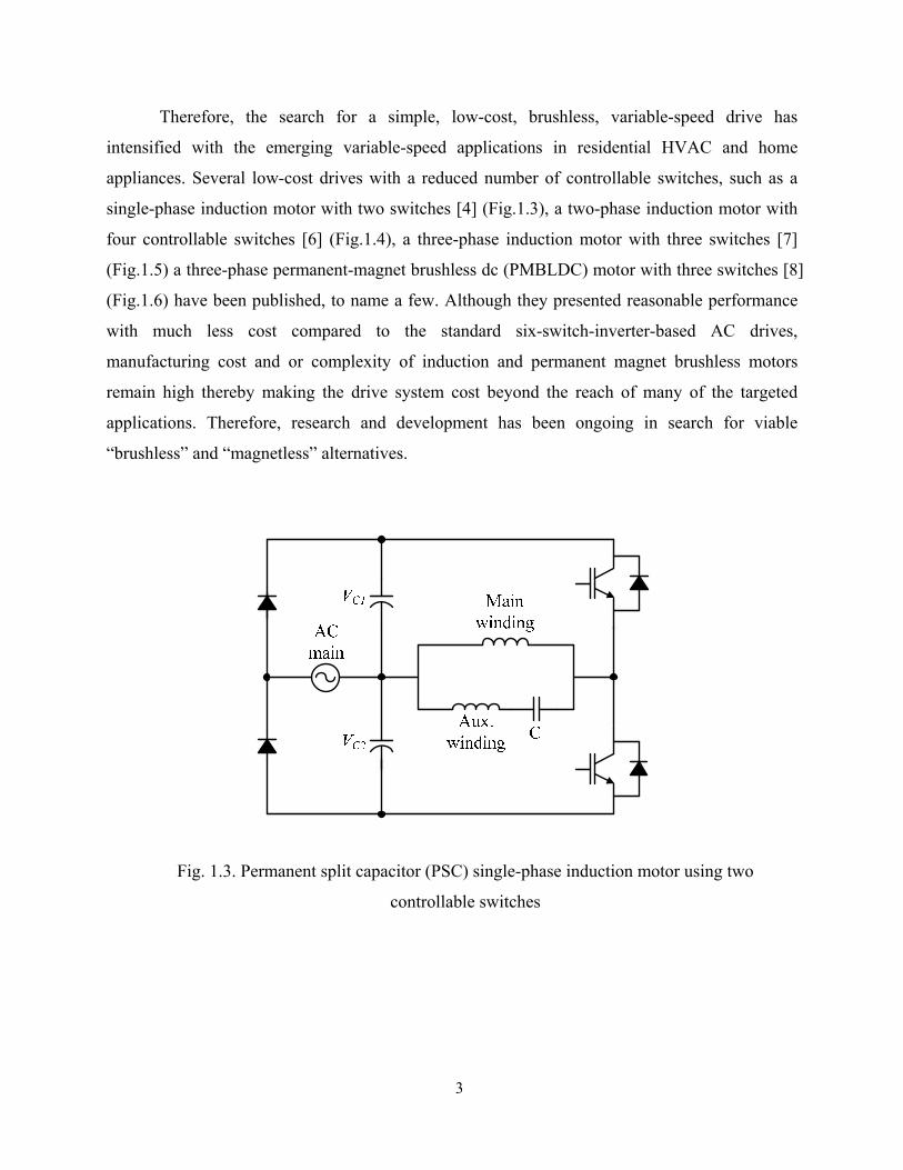
Therefore, the search for a simple, low-cost, brushless, variable-speed drive has
intensified with the emerging variable-speed applications in residential HVAC and home
appliances. Several low-cost drives with a reduced number of controllable switches, such as a
single-phase induction motor with two switches [4] (Fig.1.3), a two-phase induction motor with
four controllable switches [6] (Fig.1.4), a three-phase induction motor with three switches [7]
(Fig.1.5) a three-phase permanent-magnet brushless dc (PMBLDC) motor with three switches [8]
(Fig.1.6) have been published, to name a few. Although they presented reasonable performance
with much less cost compared to the standard six-switch-inverter-based AC drives,
manufacturing cost and or complexity of induction and permanent magnet brushless motors
remain high thereby making the drive system cost beyond the reach of many of the targeted
applications. Therefore, research and development has been ongoing in search for viable
“brushless” and “magnetless” alternatives.
Fig. 1.3. Permanent split capacitor (PSC) single-phase induction motor using two
controllable switches

4
Fig. 1.4. Two-phase induction motor drive using four controllable switches
Fig. 1.5 Asymmetric three-phase induction motor drive using three-controllable switches
AC main
VC1
VC2
Ph. A Ph. B

5
Fig. 1.6. Permanent magnet dc motor using three controllable switches
The switched reluctance motor (SRM) is known to be the lowest cost motor with the
simplest construction having no brushes, commutators, windings, or magnets on its rotor and
only concentrated windings on its stator [9],[10]. The simple configuration, along with the
features such as unidirectional flow of current and negligible mutual coupling between the
phases lends itself to a variety of motor and converter topologies for each intended application.
Key to realizing cost minimization in SRM drives is reduction in the number of machine phases,
preferably single or two-phase machines, and reduction in converter electronics, i.e., reduced
number of switching devices. The single-phase SRM is known to be the simplest machines of all,
requiring minimum amount of driving circuits. The drawbacks of the single-phase SRM,
however, include the lack of self-starting capability unless otherwise built in to the machine with
the additional mechanism such as a parking magnet, poor air-gap utilization, high peak-to-peak
torque ripple, and increased acoustic noise [11], [12]. The applications are thus limited to
applications which require limited starting torque and can tolerate large torque ripple such as
fans. With proper design, the two-phase SRM can provide reliable starting at any rotor position
without resorting to any additional apparatus. Although it may be more expensive than the
single-phase SRM due the increased copper volume and converter electronics, the two-phase

6
SRM has less torque ripple and hence less acoustic noise and with conventional 4-2 structure this
motor can still be a good candidate for high-speed vacuum cleaners.
A two-phase SRM with a two-switch-based asymmetric converter shown in Fig. 1.7 is
found to be competitive for low-cost variable-speed applications. While this drive system
provides desirable performance with significantly reduced drive electronics, a further reduction
in cost and components would be highly appealing to some sectors of industry while for many
others it is almost a necessity to meet highly cost-sensitive high-volume applications. In this
study, three different low-cost brushless variable-speed drives realized by two different two-
phase SRMs and three different low-cost converters are presented. Two novel converters for
two-phase SRMs where the energy recovery is retained within the motor are proposed. All of the
proposed drive systems are modeled, designed, analyzed, simulated, and experimentally verified.
To make the proposed systems more viable for their intended applications, position sensorless
control as well as power factor correction are also investigated and implemented. The detailed
outline of this thesis is discussed in section 1.3.
Fig. 1.7. Two-phase SRM drive with asymmetric converter
Cdc PhA PhBAC
main

7
1.2 Scope and Contributions
The scope of this research is to develop low-cost, high-efficiency, anbrushless variable
speed drives system targeting low-cost, high-volume application, such as the home appliance
markets. Three different two-phase SRM drives are designed and implemented with a focus on
minimum electronics and simple yet efficient drive control to meet the demanding requirement
from home appliance market in terms of cost, efficiency, input power factor.
The scope and key contributions made in this research include:
1) Analysis, design, simulation, and experimental verification of the proposed two-
phase, single-controllable-switch-converter based SRM drive.
2) Analysis, design, simulation, and experimental verification of the proposed two-
phase, two-controllable-switch-converter based SRM drive
3) Analysis, design, simulation, and experimental validation of the proposed two-phase,
two-switch based, high-speed SRM drive.
4) Optimal efficiency control in single-pulse mode with optimal number of winding
turns.
5) Parameter insensitive position sensorless control and its implementation with the
above proposed drive systems to achieve further cost reduction.
6) Study of effect of input power factor correction and its implementation using only
passive components and the drive structure without external electronics.
7) Comparative study of the proposed drive systems, along with the existing brush-
commutator or permanent magnet motors to provide guideline for their selection
based on the requirement for their intended applications.

8
1.3 Outline of Dissertation
The report on this research is organized into chapters as follows.
Chapter 1 introduces the motivation, review, scope and contribution of the presented
research work. In the review section, basic principle of operation of SRMs and state-of-art-
review of SRMs of the single- and two-phase SRMs as well as converter topologies for low cost
applications is discussed.
Chapter 2 briefly describes a theory behind the fundamental principles of SRM drives in
terms of principles of operation, modeling, and control of the SRM. A review of state-of-art-
converters for SRMs is also discussed.
Chapter 3 presents a novel single-controllable switch-based, two-phase SRM drive
system. In this chapter, the key design consideration for both converter and machine parameter is
discussed. The operation principle, derivation of converter modeling, dynamic simulation, and
experimental validation are also presented.
Chapter 4 presents a novel two-switch-based, two-phase SRM drive system. Converter
modes of operation and their derivation are followed. The estimation of energy transfer between
the capacitors and estimation of the secondary capacitor voltage is also presented. The key
design consideration is discussed, followed by dynamic simulation and experimental verification.
Chapter 5 presents a two-phase SRM drive system for high speed application. Modeling
of the converter and motor is presented and then the effect of angle control as a main control
parameter is characterized and discussed. Converter modes of operation and their derivation are
followed. The effect of winding number turn as a key design parameters is studied and it optimal
selection is discussed.
Chapter 6 presents a new position sensorless control algorithm. The brief review of state-
of-art sensorless methods is discussed. Then, derivation of the proposed algorithm is followed.

9
Digital implementation as well as simulation is also presented and experimental verification on
the proposed drive system is presented.
Chapter 7 summarizes the results and provides the key conclusions of this research work.
Advantages and limitations of the proposed system will be reviewed. Ongoing and future related
work will be discussed

10
Chapter 2
SRM Fundamentals and
State-of-the-Art-Review of SRM Converters
2.1 SRM Fundamentals
The SRM is a doubly salient motor with simple mechanical construction. The rotor is
made of sheets of laminated steel with no windings or permanent magnets on it. The stator is also
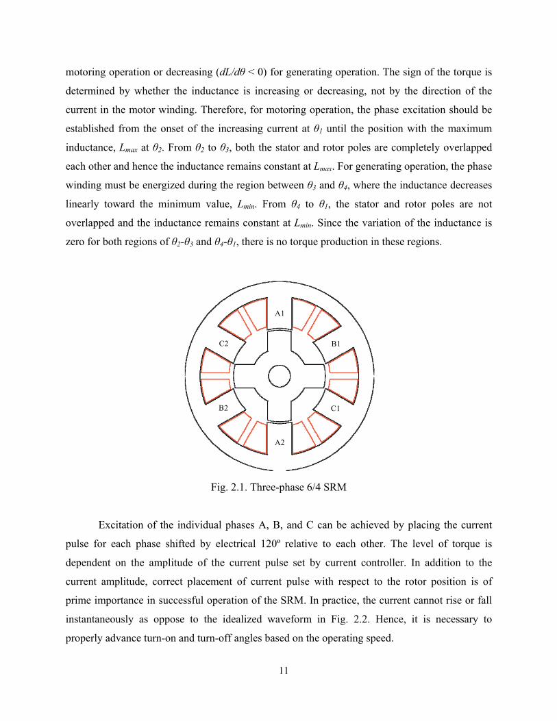
made of sheets of laminated steel with concentrated windings wound on the stator poles. Fig. 2.1
shows a conventional three-phase 6/4 SRM with six salient poles on the stator and four salient
poles on the rotor. The windings on each diametrically opposite pole pair are connected in series
forming an individual stator phase. The motor is driven by a sequence of current pulses applied
in each phase. The individual phases are consequently energized, forcing the motor to rotate. The
resulting torque is created based on reluctance forces which lead to a pair of rotor poles moving
into alignment with the excited stator pole pairs.
2.1.1 Principles of Operation
Fig. 2.2 shows the idealized profiles of inductance, current, and corresponding torque
with respect to the rotor position for a phase of the three-phase 6/4 SRM. Waveforms for only
one phase are shown. Each cycle (equal to the rotor pole pitch) has four distinct regions of
inductance profile. Since torque production is associated with derivative of the inductance with
rotor position, current is desired only where the inductance is either increasing (dL/dθ > 0) for
11
motoring operation or decreasing (dL/dθ < 0) for generating operation. The sign of the torque is
determined by whether the inductance is increasing or decreasing, not by the direction of the
current in the motor winding. Therefore, for motoring operation, the phase excitation should be
established from the onset of the increasing current at θ1 until the position with the maximum
inductance, Lmax at θ2. From θ2 to θ3, both the stator and rotor poles are completely overlapped
each other and hence the inductance remains constant at Lmax. For generating operation, the phase
winding must be energized during the region between θ3 and θ4, where the inductance decreases
linearly toward the minimum value, Lmin. From θ4 to θ1, the stator and rotor poles are not
overlapped and the inductance remains constant at Lmin. Since the variation of the inductance is
zero for both regions of θ2-θ3 and θ4-θ1, there is no torque production in these regions.
Fig. 2.1. Three-phase 6/4 SRM
Excitation of the individual phases A, B, and C can be achieved by placing the current
pulse for each phase shifted by electrical 120º relative to each other. The level of torque is
dependent on the amplitude of the current pulse set by current controller. In addition to the
current amplitude, correct placement of current pulse with respect to the rotor position is of
prime importance in successful operation of the SRM. In practice, the current cannot rise or fall
instantaneously as oppose to the idealized waveform in Fig. 2.2. Hence, it is necessary to
properly advance turn-on and turn-off angles based on the operating speed.
A1
A2
C2
C1
B1

12
Fig. 2.2. Idealized waveforms of a phase of the three-phase 6/4 SRM
(Inductance, current, and torque profiles)
2.1.2 Mathematical Model of SRM
The SRM is a highly nonlinear system. Based on the non-linear theory describing the
behavior of the motor, a mathematical model of an SRM can be created. The mathematical
model enables simulation of the SRM system and hence development and implementation of
sophisticated algorithms for controlling the SRM is feasible. The electromagnetic dynamics of an

13
SRM can be represented using Faraday’s Law. For an N-phase SRM, the stator voltage equation
for a phase coil can be expressed in terms of the phase currents and flux linkages:
kkk
N
n
nkn iRvdt
id−=∑
=1
),(θλ (2.1)
where θ is the rotor position, ik is the phase current, vk is the phase voltage, and Rk is the
resistance of the phase coil respectively. Generally, the effect of mutual coupling in an SRM is
negligible. Thus, the stator voltage equation can be given as
kkkk Riv
dtid
−=),(θλ
(2.2)
Using the chain rule, (2.2) can be rewritten as
kk
kk
kkk
k
kkkkk
edtdiil
dtdi
dtdi
iiiRv
+=
∂∂
+∂
∂=−
),(
),(),(
θ
θθθλθλ
(2.3)
Since the flux is the product of inductance and current, λk = Lkik , (2.3) can also be rewritten as
kk
kk
ph
phph
ph
ph
phphph
phphph
ph
phphkkk
edtdiil
dtd
iiL
idt
diiiL
iiL
dtdiiL
dtdi
iiiL
iRv
+=
∂
∂+⎟
⎟⎠
⎞⎜⎜⎝
⎛
∂
∂+=
∂
∂+
∂
∂=−
),(
),(),(),(
),(),(
θ
θθθθ
θθθθ
(2.4)
From (2.2) and (2.3), lk(θ,ik) and ek are the incremental inductance and back-EMF respectively.

14
⎟⎟⎠
⎞⎜⎜⎝
⎛∂
∂+=
∂∂
=k
kkk
k
kkkk i
iiiLi
iil ),(),(),(),( θθθλθ (2.5)
dtdiLi
dtdie k
kk
kθ
θθθ
θθλ
∂∂
=∂
∂=
),(),( (2.6)
The electromagnetic torque of the SRM is given as
∑= ∂∂
=N
k
kcke
iWT1
),(θθ
(2.7)
where k
i
kkkck diiiW k
∫= 0),(),( θλθ is the co-energy. In the linear operating region, the
electromagnetic torque can be expressed in terms of derivative of the phase inductances and the
square of the phase currents:
∑=
=N
k
kke d
dLiT1
2 )(21
θθ
(2.8)
Using the stator voltage equation and the load dynamic equation, the mathematical model
of N-phase SRM can be given by (2.9) and (2.10) and its block diagram representation is
depicted in Fig. 2.3. To calculate the current and torque waveforms, the dynamic model of an
SRM has to be solved, i.e. the differential equations for all N phases’ stator voltages and the
mechanical equation have to be integrated simultaneously as shown in Fig. 2.3.
⎥⎥⎥⎥
⎦
⎤
⎢⎢⎢⎢
⎣
⎡
⎥⎥⎥⎥
⎦
⎤
⎢⎢⎢⎢
⎣
⎡
−
⎥⎥⎥⎥
⎦
⎤
⎢⎢⎢⎢
⎣
⎡
=
⎥⎥⎥⎥⎥⎥⎥
⎦
⎤
⎢⎢⎢⎢⎢⎢⎢
⎣
⎡
NNNNN i
ii
R
RR
v
vv
dtid
dtid
dtid
M
L
OM
M
L
MM
1
1
2
1
2
1
21
11
000
000
),(
),(
),(
θλ
θλ
θλ
(2.9)
⎥⎦
⎤⎢⎣
⎡−−= ∑
=
n
kLkk TBiT
Jdtd
1),(1 ωθω
(2.10)

15
Fig. 2.3. Block diagram representation of dynamic mathematical model of an n-phase SRM
First, the flux and rotor speed is calculated from the integration and then the phase
current and the torque is calculated from the lookup tables of magnetization and torque
characteristics obtained from either finite element analysis (FEA) simulation or curve fit based
off a few measured data sets.
The electromagnetic circuit of the SRM is characterized by non-linear magnetization
which is a function between the magnetic flux, the phase current, and the motor position. The
influence of the phase current is most apparent in the aligned position, where saturation effects
can be observed. The torque generated by the motor phase is a function of the magnetic flux.
Therefore, the phase torque is not constant for constant phase current for different motor
positions. This contributes to torque ripple and acoustic noise.
∫
∫
MM M
∫ ∫
i1λ1
iNλN

16
2.1.3 Control of SRM
Torque production of the SRM resembles that of stepper motors in that coils in the stator
serve as electromagnets that attract the nearest rotor poles. One of the important differences
between the SRM and the stepper is that while a stepper operates open loop, an SR motor does
not operate open loop but rather monitors its rotor position. Stator coils are energized in
synchronism with the rotor and only when it is advantageous to do so. Fig. 2.4 depicts a cascaded
control configuration for SRM drives. The outermost control loop is, in general, speed control,
but it can be position control in case of servo drives. The innermost loop is generally current
control which is implemented by either hysteresis or linear PI controller. If the drive does not
require torque control or high performance, average phase voltage control by PWM chopping
may be more desirable than current control. In that case, torque controller is not needed. Another
important control block is control of switching angles (turn-on, turn-off) for proper placement of
current pulses in synchronism with rotor position. Once the current reference and switching
angles are defined, the proper sequence of excitation for each phase, so called “commutation” is
executed. Therefore, performance of the SRM drives hinges on the performance of the current
controller as well as correct placement of the current excitation. This leads to important control
parameters of SRM drives: current reference, turn-on angle, turn-off angle.
Fig. 2.4. Cascaded control block diagram for an SRM drive.
A torque-speed characteristic for SRMs is shown in Fig. 2.5. At low speeds, the motor
back-EMF is much smaller than source voltage thereby allowing rapid buildup and decay of the

17
phase current. Therefore, torque production can be achieved mainly by current control with fixed
or small variation of switching angles. As the speed increases, the motor back-EMF becomes
significant and this slows the rise and the fall of current in the phase winding. Because the rate of
current rise is slower, the rotor traverses a significant angle in the time it takes the current to rise
to the commanded value and this results in loss of torque. Therefore, it is necessary to advance
the turn-on angle in order to build current in the phase winding before the onset of pole overlap,
and to extinguish the current before substantial braking torque is generated. Thus, control of
switching angles becomes significant for higher speeds. The operation region below the base
speed, ωb is called current-limited or constant-torque region since the current and torque
production should be limited and torque can be maintained at any speed by current control.
Fig. 2.5. SRM torque-speed characteristics
When the speed increases beyond the base speed, the back-EMF exceeds the supply
voltage. In this region, PWM chopping is not achievable and hence the required torque is
produced by advancing the turn-on angle significantly and thus increasing dwell angle. The
current is switched on and off only once in each conduction period, thereby called “single-pulse
operation”. Switching angles are only parameters to control torque. The operation region beyond
the base speed is called constant power region and torque in this region falls off inversely
proportional to speed (1/ω). If the speed increases even further beyond the point at which where

18
the maximum dwell angle is reached (ωp), the motor enters maximum dwell region. Maintaining
torque above this speed is not possible, and the torque falls off inversely proportional to square
of speed (1/ω2).
2.2 State-of-the-Art-Review of SRM Converters Unlike the induction motors or dc motors, the SRMs cannot run directly from an ac or dc
power supply. A certain amount of control via a power electronic converter as an electronic
commutator is required to control the supply of the current to the phase winding. Hence, the
power converter has been one of the main research aspects of the SRM drives since the
performance and cost of the drive is highly affected by the converter configuration. A large
number of converter topologies have been proposed hitherto and their comparative studies have
been published in [10], [13]-[17] to facilitate the selection of an appropriate converter topology
for a wide range of applications. Several important requirements to be considered for designing
or selecting a converter topology for the SRM are summarized as below.
• In an SRM, the torque is produced irrespective of the direction of the flux through
the stator and rotor poles. Thus, only a unidirectional flow of phase current is
required resulting in simpler and more reliable power converter circuits.
• The purpose of power converter circuit is to provide some means of increasing the
supply of current to the phase winding. Hence, for the purpose of the phase current
control, it is necessary to modulate the phase voltage. This is especially important at
low speed, when the motor back-EMF is low.
• The magnetic field energy stored in the winding has to be provided with a path
during commutation of a phase so that the surplus energy returned to the power
supply rails without resulting in excessive voltage across the windings.
• For maximum control flexibility, the converter should be capable of providing three
different excitation modes: positive voltage, negative voltage, zero voltage modes.
• The demagnetization voltage needs to be as high as possible in order to achieve fast
fall time of the phase winding current should be as fast as possible.

19
• Large fall time of phase current results in negative torque and this time can be
reduced if demagnetizing voltage is as high as possible.
• To reduce system cost, a low number of semiconductor switches is desirable.
• To reduce the torque ripple, it is necessary, at the same time, to control current in
one phase and force demagnetizing of other phase of the motor.
In this section, the review of the converter topologies for SRM drives so far published is
discussed. There are several factors for characterizations of the converter topologies but in
general the converters can be classified by either the number of the controllable switches or the
way the energy stored in the phase windings is managed.
2.2.1 Classification Based on the Number of Controllable Switches Fig.2.6 shows the classification of the SRM converters based on the number of the
required controllable switches. The SRM requires at least one controllable switch per phase for
basic commutation of the operation. This leads itself to a single-switch-per-phase configuration
which requires the minimum number of the switches among the existing converter topologies.
However, to achieve more control flexibility additional switches are inevitable. In general, the
converters with more switches per phase deliver more control flexibility and better performance
but more expensive is their system cost. Detailed description of the converters for each category
is as follows.

20
Fig. 2.6. Classification of the SRM converters based on the number of the controllable switches
2.2.1.1 Two-switch-per-phase Converters Asymmetric converter [18]-[20]: The classic asymmetric bridge converter shown in Fig.
2.7 is one of the most widely used topologies. The asymmetric converter employs two switches
per phase, with two freewheeling diodes to return the regenerative energy to the supply, hence
requiring total of 2N switches and 2N diodes. The converter has the advantages of complete
control of each phase winding. However, the per-phase component count is high due to the total
number of switches along with their associated drive circuits thus making the drive system
expensive. Therefore, the bridge converter is best fit for high performance applications, where
the cost of the converter is not of prime importance.
Two-switch-per-phase (2N switches)
• Equal sharing • Common switch• Dual-decay • Sood• C-dump
• Modified C-dump 1• Modified C-dump 2• Parallel C-dump• Series C-dump • Energy efficiency C-dump
• Variable dc link• Front-end buck• Front-end buckboost
• Resonant
N+1 switch Single-switch-per-phase
(N switches)
• Asymmetric bridge • Modified asymmetric
• Suppression resistor• R-dump• R-dump + zener
• Bifilar• Split source
• Split DC• Split AC
• Single-switch, two-diode
Converter topologiesfor N-phase SRM

21
Fig. 2.7. Asymmetric bridge converter (only one bridge for one phase is shown)
2.2.1.2 N+1 Switch-Per-Phase Converters
The converters in this category have total of N+1switches, where N is the number of
motor phases. There are several different configurations under this category and they are
discussed as below.
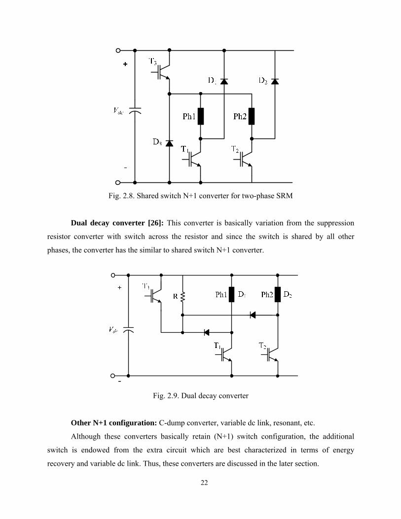
Configuration with a common shared switch [21],[22]: Each phase of the motor
requires only one diode and switch and there is an additional switch and a diode, shared by all
phases for phase commutation. Although this converter has fewer switches than bridge converter
it has the critical disadvantage that the commutation cannot be used until the other phase has
been completely demagnetized making phase independence impossible. It does not tolerate phase
overlapping, and therefore, its capability is very limited, particularly for the single-pulse mode.
22
Fig. 2.8. Shared switch N+1 converter for two-phase SRM
Dual decay converter [26]: This converter is basically variation from the suppression
resistor converter with switch across the resistor and since the switch is shared by all other
phases, the converter has the similar to shared switch N+1 converter.
Fig. 2.9. Dual decay converter
Other N+1 configuration: C-dump converter, variable dc link, resonant, etc.
Although these converters basically retain (N+1) switch configuration, the additional
switch is endowed from the extra circuit which are best characterized in terms of energy
recovery and variable dc link. Thus, these converters are discussed in the later section.

23
2.2.1.3 Single-Switch-Per-Phase Converters The converters employing the single-switch-per-phase configuration requires total of N
switches for an N phase motor. They are appealing specifically to low cost, low performance
drives due to their compactness of the converter package and hence a possible reduction in their
cost compared to other converters. They have disadvantage of being unable to apply zero voltage
across the winding and thus the soft chopping is not achievable, leading to higher current ripple
than two-switch-per-phase or N+1 switch converters. There several different configurations in
this category.
Suppression resistor (R-dump) converter [23]-[25]: Converters shown in Fig. 2.10
uses an external resistor to generate the suppression voltage across the winding. This has the
disadvantage that the energy is dissipated in a resistor, thus reducing the overall efficiency of the
drive system. When a zener diode is employed with the dump resistor, a higher value of
suppression voltage during the freewheeling period is sustained.
(a) Dump resistor (b) Dump resistor with Zener diode
Fig. 2.10. Suppression resistor (R-dump) converters (only one phase of the motor shown)
Bifilar Winding Converter [18]-[19]: This converter has one transistor and one diode
per phase hence employing the single-switch-per-phase (SSPP) configuration (Fig.2.11). The

24
converter regenerates the stored magnetic energy to the source. This is achieved by having a
bifilar winding with opposite polarity between primary and secondary bifilar winding for each
phase. The voltage reflected into the main winding is dependent upon the turns ratio of the
windings. Although this converter employs a SSPP configuration, a significant drawback of this
converter is that the voltage stress seen by the switch is very high and the motor require a bifilar
winding.
Fig.2.11. Bifilar converter
Split dc Supply Converter [10],[25]
This topology also preserves one switch per phase. As shown in Fig. 2.12, It has two dc
capacitors, splitting the dc link. The voltage available for each capacitor is half the full dc link
voltage. This converter has drawbacks of having half the dc supply voltage, Vdc/2 applied to the
motor winding and voltage asymmetry between two dc link capacitors. Balancing the charge
across the dc link capacitors is very important; the number of machine phases has to be even and
not odd. Another drawback of this converter is that freewheeling mode is not possible with this
converter. A modified version of this converter is called “Split ac supply” which utilizes the half-
bridge rectifier, and the dc link mid-point is tied to ac supply neutral thus splitting ac supply.
Therefore, each dc link capacitor is charged at every alternate half cycle of the supply voltage
and the capacitor voltage applied to the phase winding is Vdc instead of Vdc/2.
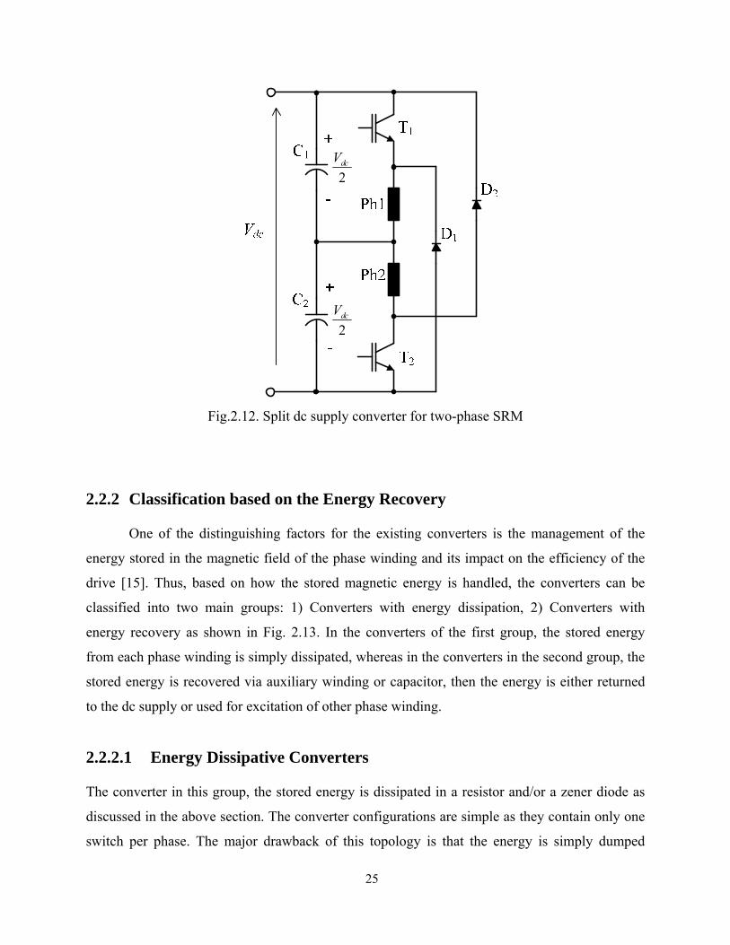
25
Fig.2.12. Split dc supply converter for two-phase SRM
2.2.2 Classification based on the Energy Recovery
One of the distinguishing factors for the existing converters is the management of the
energy stored in the magnetic field of the phase winding and its impact on the efficiency of the
drive [15]. Thus, based on how the stored magnetic energy is handled, the converters can be
classified into two main groups: 1) Converters with energy dissipation, 2) Converters with
energy recovery as shown in Fig. 2.13. In the converters of the first group, the stored energy
from each phase winding is simply dissipated, whereas in the converters in the second group, the
stored energy is recovered via auxiliary winding or capacitor, then the energy is either returned
to the dc supply or used for excitation of other phase winding.
2.2.2.1 Energy Dissipative Converters
The converter in this group, the stored energy is dissipated in a resistor and/or a zener diode as
discussed in the above section. The converter configurations are simple as they contain only one
switch per phase. The major drawback of this topology is that the energy is simply dumped
2dcV
2dcV

26
during each commutation process resulting in a low efficiency converter. However, this
inefficiency is more than compensated by their simplicity, low cost and low component count.
Fig.2.13. Classification of the SRM converters based on energy recovery
2.2.2.2 Energy Recovery (Regeneration) Converters As shown in Fig.2.13, the converters in this group are divided into two categories: 1)
passive recovery, 2) active recovery converters. The passive recovery converters can be further
split into two groups: i) magnetic regeneration – The converters in which the energy is
regenerated via bifilar windings or auxiliary windings and then is returned to the source, ii)
Energy dissipation
• Bifilar• Aux.winding
Converter topologiesfor N-phase SRM
• R-dump• R+zener dump• Dual decay
Energy recovery
Passive recovery Active recovery(extra circuit)
• C-dump (Class I)• Original C-dump• Freewheeling C-dump• Energy efficiency C-dump
• C-dump (Class II)• Front-end dc-dc (variable dc link)
• Buck• Buckboost
Magnetic Capacitive(direct regeneration)
• Asymmetric• Split dc, split ac• Sood• Single-switch, two-diode• N+1 (shared switch, equal sharing)

27
capacitive regeneration – The converters in which the stored energy is regenerated via the boost
or storage converter or directly to the dc link capacitor. Active recovery converters with
integrated dc–dc energy recovery circuits transfer energy stored in the magnetic field of the
phase winding to an auxiliary capacitor. A dc–dc converter is used to transfer energy from the
auxiliary capacitor of the system and ensure that no capacitor becomes under or overcharged.
The disadvantages of these converters are control complexity and extra components required for
the chopper circuit, leading to increased cost and size. The power semiconductor devices must be
rated for the boost voltage. The active recovery converters can be further classified into two
categories: C-dump converters and variable dc link converters.
C-dump Converter – Class I [20],[27],[28]: The original C-dump converter and other
variants of this topology are shown in Fig. 2.14. The stored magnetic energy is partially diverted
to the dump capacitor and recovered from it by the single quadrant chopper and sent to the dc
source. The main disadvantage of this circuit is that the current commutation is limited by the
difference between voltage across dump capacitor, output voltage, and the dc link voltage. Fast
commutation of currents requires high voltage, which results in increasing the voltage rating of
the power devices. Further, the energy circulating in spite of the advantages of full regenerative
capability and faster demagnetization, the regenerative C-dump converter has disadvantages of
complicated control and extra cost for additional components making this converter less
competitive for low cost application. Even though this converter uses a fewer number of devices,
the circulating energy in the chopper circuit is a large fraction of the total throughput. Therefore,
chopper components are not small and the losses in these components reduce the efficiency of
the converter.
C-dump Converter – Class II [13],[17],[29]: The auxiliary inductance might be
replaced by a motor phase, so that instead of recovered energy from all motor phases being
circulated back to dc link capacitor through a chopper circuit the recovered energy can be used to
energize the remaining phases of the SRM; hence all or part of recovered energy is retained with
the machine, leading to higher efficiency compared to conventional C-dump converters. Fig.
2.15 shows two types of converters which fall in this category.

28
(a) Original C-dump converter
(b) Freewheeling C-dump converter (without auxiliary inductor)
(c) Energy-efficient C-dump converter
Fig. 2.14. C-dump converters with the stored energy circulated to dc link (class I)

29
(a) Type 1
(b) Type 2
Fig.2.15. C-dump converters with the auxiliary inductor replaced by the phase winding (class II)
(Recovered energy is used to energize the remaining phase.)
+
-
Vdc
T1
T2
Ph1 Ph2
D1D2
Cd Ph3
T3
Dd
30
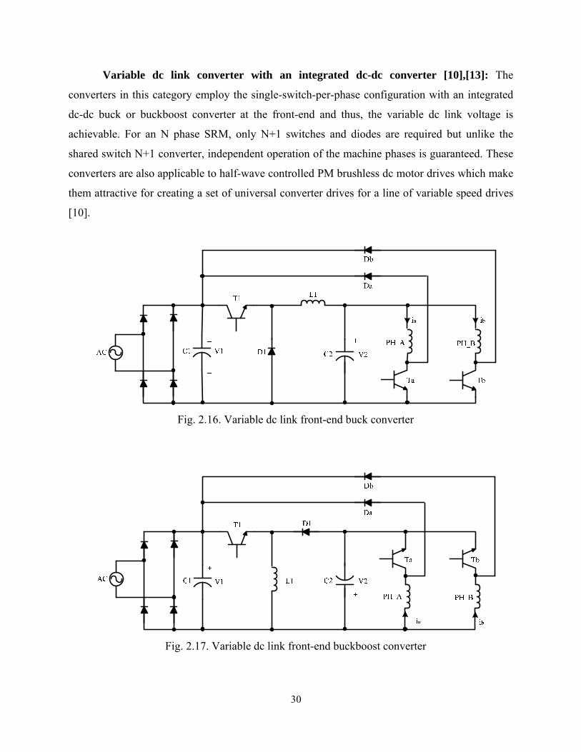
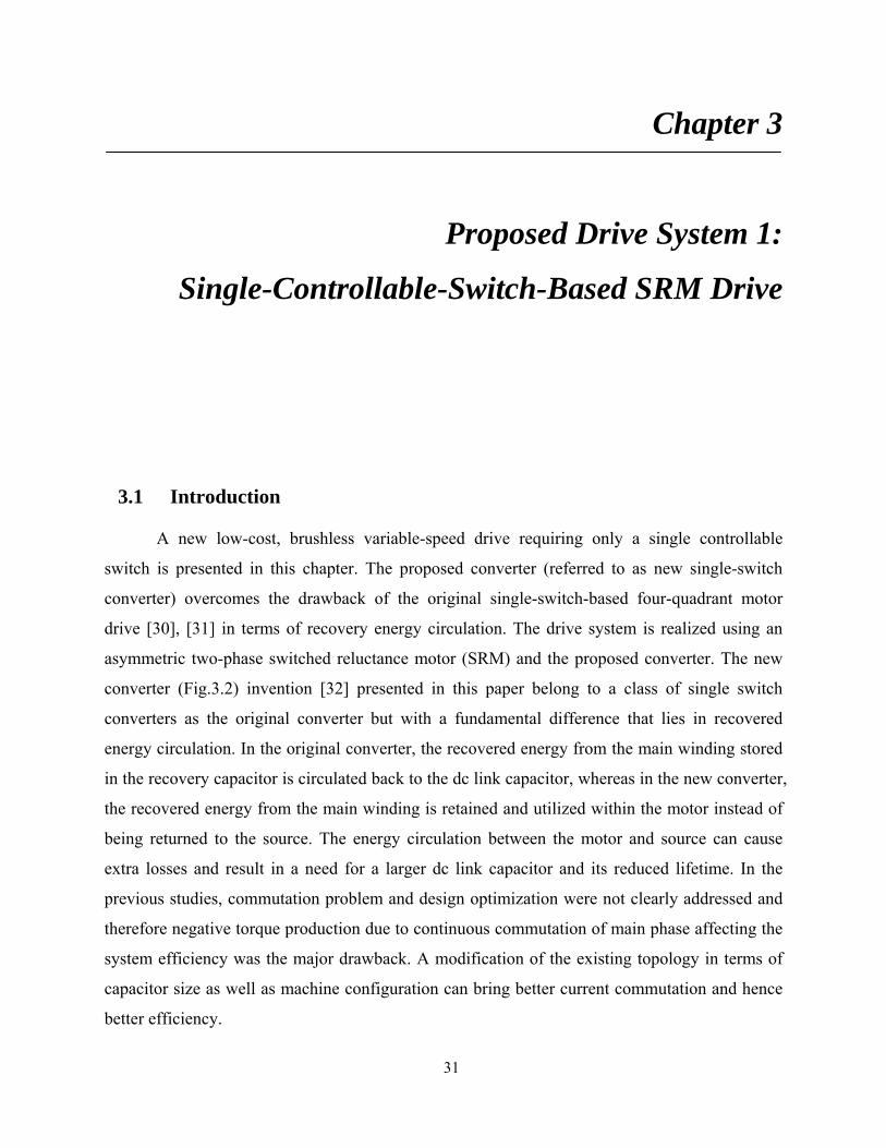
Variable dc link converter with an integrated dc-dc converter [10],[13]: The
converters in this category employ the single-switch-per-phase configuration with an integrated
dc-dc buck or buckboost converter at the front-end and thus, the variable dc link voltage is
achievable. For an N phase SRM, only N+1 switches and diodes are required but unlike the
shared switch N+1 converter, independent operation of the machine phases is guaranteed. These
converters are also applicable to half-wave controlled PM brushless dc motor drives which make
them attractive for creating a set of universal converter drives for a line of variable speed drives
[10].
Fig. 2.16. Variable dc link front-end buck converter
Fig. 2.17. Variable dc link front-end buckboost converter
31
Chapter 3
Proposed Drive System 1:
Single-Controllable-Switch-Based SRM Drive
3.1 Introduction
A new low-cost, brushless variable-speed drive requiring only a single controllable
switch is presented in this chapter. The proposed converter (referred to as new single-switch
converter) overcomes the drawback of the original single-switch-based four-quadrant motor
drive [30], [31] in terms of recovery energy circulation. The drive system is realized using an
asymmetric two-phase switched reluctance motor (SRM) and the proposed converter. The new
converter (Fig.3.2) invention [32] presented in this paper belong to a class of single switch
converters as the original converter but with a fundamental difference that lies in recovered
energy circulation. In the original converter, the recovered energy from the main winding stored
in the recovery capacitor is circulated back to the dc link capacitor, whereas in the new converter,
the recovered energy from the main winding is retained and utilized within the motor instead of
being returned to the source. The energy circulation between the motor and source can cause
extra losses and result in a need for a larger dc link capacitor and its reduced lifetime. In the
previous studies, commutation problem and design optimization were not clearly addressed and
therefore negative torque production due to continuous commutation of main phase affecting the
system efficiency was the major drawback. A modification of the existing topology in terms of
capacitor size as well as machine configuration can bring better current commutation and hence
better efficiency.

32
Fig. 3.1. Original single-controllable-switch converter
Fig. 3.2. New single-controllable-switch converter
33
The new single-switch converter has the advantage over the previous converter in term of
less capacitor rating while preserving all the advantages of the original circuit is proposed. The
key design aspects of the converter as well as optimal commutation strategy are presented. The
new drive system retains the unique features of self-starting for all rotor position and four
quadrant operation of the original single-switch-based switched reluctance motor drive system.
This chapter paper presents the operation principle and modeling of the new converter
coupled with the considered motor, the design consideration for optimal commutation in single-
pulse mode, and comparison with other conventional converters and the original converter.
Simulation results are based on a nonlinear model of the motor drive system. A prototype drive
has been built and tested to verify its practical viability. The experimental results correlate well
with the simulation, and demonstrate a performance comparable to conventional asymmetric
bridge converter based drive with two switches per phase. The market relevance of this new
drive system is primarily due to its lowest cost structure, packaging compactness, self-starting
feature, variable-speed operation and four-quadrant capability. Because of these features, the
new drive system offers a viable alternative for conventional fixed speed brush-commutator
motors and variable- speed permanent magnet brushless dc motor drives in many high volume
applications in the low-cost, energy efficient, high-volume categories such as fans, blowers, hand
tools and home appliances.
3.2 Proposed Drive System
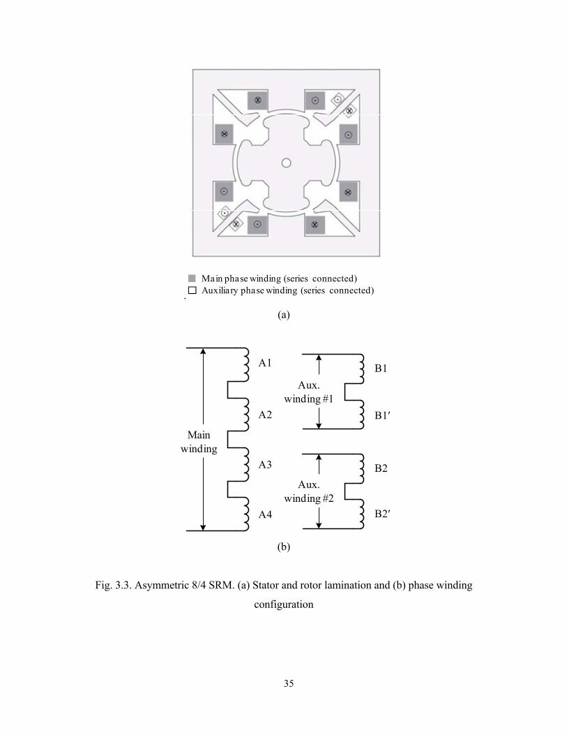
3.2.1 Asymmetric 8/4 SRM Configuration
Figs. 3.3(a) and 3.3(b) show the configuration of the SRM along with the stator windings,
employed in the proposed drive system. The motor has a unique structure such that it has eight
salient poles (four main and four auxiliary) on its stator and four salient poles on its rotor, hence
referred to as asymmetric two-phase 8/4 SRM. Four large poles with series connected windings
form a main phase and two sets of diagonally opposite small poles with the series–connected
windings form two auxiliary phases. The stator inner diameter and the back iron diameter are 74.5
mm (2.933 in) ands 102 mm (4.016 in) respectively. The outer stator width is 75 mm (2.953 in)
34
and the rotor outer diameter is 73.8 mm (2.906 in). The rotor poles are slightly larger with a width
of 26.5 mm (1.043 in) and a radius of curvature of 40 degrees. The rotor stack length is 18 mm
(0.709 in). The rotor shaft diameter is 6.25 mm (0.246 in). The case of the machine is square with
a side length of 135 mm (5.315 in). The stack length is 10 millimeters (0.394 in). While this
motor has two phases, they are not identical. The main phase produces most of the torque in the
machine, whereas the auxiliary phase is mainly intended for energy recovery for commutation of
the main phase current and also aids in self-starting and speed reversal for four-quadrant
operation. The reliable self-starting is achieved by supplying the auxiliary windings with a small
pulsed current that will pull the nearest rotor poles to complete alignment with the auxiliary poles.
Note that in this position the rotor poles are completely unaligned with respect to the main stator
poles. Then excitation of the main stator poles at this time will generate an air gap torque turning
the rotor. The pole size and number of turns for each phase are optimized for the cost and
performance of the drive system. In the current experimental system, only one set of diametrically
opposite auxiliary windings are utilized. This reduces the machine into an equivalent of a two
phase SRM. The motor is designed to run at a rated speed of 5000 r/min and maximum speed of
10,000 r/min. The parameters and specification for this motor are available in Appendix A.
The major features of the proposed machine include:
• Provides starting capability in both directions unlike other single-phase SRM
configurations and, therefore, this is the only single-phase configuration capable of
four-quadrant operation.
• Does not use permanent magnets thus reducing the manufacturing complexity and cost
• The auxiliary pole windings can be used, in addition to self-starting, for probing to
determine the rotor position or as an inactive phase.
• After starting, the auxiliary poles need not be used for continuous operation of the
machine as the main winding itself, and can be used for sensing the rotor position.
• Since the interpole winding is only used for a small amount of time (during starting), it
can be designed to have a very small volume of copper thereby reducing its cost.
During the sensing part of the cycle, its current is very small even if its duty cycle is
high and, therefore, a small copper volume design is adequate.
35
.
(a)
(b)
Fig. 3.3. Asymmetric 8/4 SRM. (a) Stator and rotor lamination and (b) phase winding
configuration
Main phase winding (series connected)Auxiliary phase winding (series connected)
A1
A2
A3
A4
B1
B1′
B2
B2′
Mainwinding
Aux.winding #1
Aux.winding #2

36
3.2.2 Asymmetric 8/4 SRM Model Characterizations
The SRM is a highly nonlinear system. The nonlinear theory describing the behavior of
the motor has been developed. Based on the theory, a mathematical model can be created. On
one hand it enables simulation of the SRM system and, on the other hand, development and
implementation of sophisticated algorithms for controlling the SRM is feasible. The
electromagnetic circuit of the SRM is characterized by non-linear magnetization. Thus, for
analysis, simulation, and control of the proposed drive system, the nonlinear electromagnetic
characteristics of the motor are obtained using two-dimensional finite element analysis (FEA).
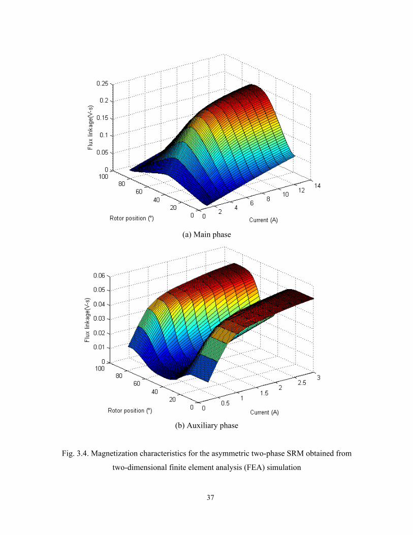
The magnetization characteristics, inductance profiles, and torque profiles for each phase
at some different current levels are shown in Figs. 3.4, 3.5, and 3.6, respectively. The flux lines
for the main phase with 4A excitation and those for the auxiliary phase with 1A excitation are
also plotted in Fig. 3.7. Fig. 3.4 illustrates a magnetization characteristic for the proposed SRM.
It is a function between the magnetic flux linkage, the phase current, and the rotor position. The
magnetization characteristic curve defines the nonlinearity of the motor. The influence of the
phase current is most apparent in the aligned position, where saturation effects can be observed.
The inductance profiles for both main and auxiliary phase at different excitation currents are
plotted over a commutation cycle in Fig. 3.5(a) and 3.5(b) respectively. The torque generated by
the motor phase is a function of the magnetic flux. Hence, the phase torque is not constant for
constant phase current for different rotor positions resulting as shown in Fig. 3.6.
37
(a) Main phase
(b) Auxiliary phase
Fig. 3.4. Magnetization characteristics for the asymmetric two-phase SRM obtained from
two-dimensional finite element analysis (FEA) simulation

38
(a) Main phase
(b) Auxiliary phase
Fig. 3.5. Inductance for the two-phase 444 SRM obtained from two-dimensional finite
element analysis (FEA) simulation
0 10 20 30 40 50 60 70 80 900.005
0.01
0.015
0.02
0.025
0.03
0.035
0.04
0.045
Rotor position (°)
Indu
ctan
ce (H
)
2A4A6A8A10A
0 10 20 30 40 50 60 70 80 900.005
0.01
0.015
0.02
0.025
0.03
0.035
0.04
0.045
Rotor position (°)
Indu
ctan
ce (H
)
1A1.5A2A2.5A3A

39
(a) Main phase
(b) Auxiliary phase
Fig. 3.6. Torque for the two-phase 444 SRM obtained from two-dimensional finite element
analysis (FEA) simulation
0 10 20 30 40 50 60 70 80 90-2.5
-2
-1.5
-1
-0.5
0
0.5
1
1.5
2
2.5
Rotor position (°)
Torq
ue (N
-m)
2A4A6A8A10A
0 10 20 30 40 50 60 70 80 90-0.4
-0.3
-0.2
-0.1
0
0.1
0.2
0.3
0.4
Rotor position (°)
Torq
ue (N
-m)
1A1.5A2A2.5A3A

40
(a) Flux line of the main phase energized with 4A excitation at aligned position
(b) Flux lines of the auxiliary phase energized with 1A excitation at aligned position
Fig. 3.7. Flux lines for main and auxiliary phase at aligned positions
41
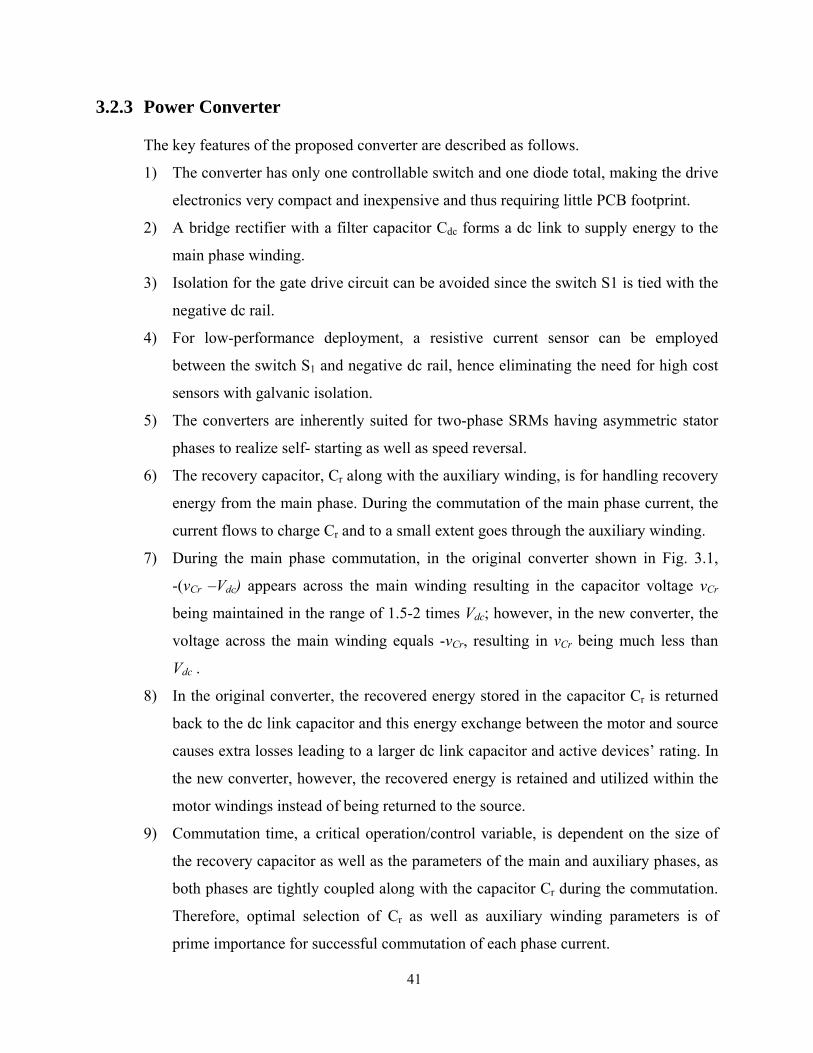
3.2.3 Power Converter
The key features of the proposed converter are described as follows.
1) The converter has only one controllable switch and one diode total, making the drive
electronics very compact and inexpensive and thus requiring little PCB footprint.
2) A bridge rectifier with a filter capacitor Cdc forms a dc link to supply energy to the
main phase winding.
3) Isolation for the gate drive circuit can be avoided since the switch S1 is tied with the
negative dc rail.
4) For low-performance deployment, a resistive current sensor can be employed
between the switch S1 and negative dc rail, hence eliminating the need for high cost
sensors with galvanic isolation.
5) The converters are inherently suited for two-phase SRMs having asymmetric stator
phases to realize self- starting as well as speed reversal.
6) The recovery capacitor, Cr along with the auxiliary winding, is for handling recovery
energy from the main phase. During the commutation of the main phase current, the
current flows to charge Cr and to a small extent goes through the auxiliary winding.
7) During the main phase commutation, in the original converter shown in Fig. 3.1,
-(vCr –Vdc) appears across the main winding resulting in the capacitor voltage vCr
being maintained in the range of 1.5-2 times Vdc; however, in the new converter, the
voltage across the main winding equals -vCr, resulting in vCr being much less than
Vdc .
8) In the original converter, the recovered energy stored in the capacitor Cr is returned
back to the dc link capacitor and this energy exchange between the motor and source
causes extra losses leading to a larger dc link capacitor and active devices’ rating. In
the new converter, however, the recovered energy is retained and utilized within the
motor windings instead of being returned to the source.
9) Commutation time, a critical operation/control variable, is dependent on the size of
the recovery capacitor as well as the parameters of the main and auxiliary phases, as
both phases are tightly coupled along with the capacitor Cr during the commutation.
Therefore, optimal selection of Cr as well as auxiliary winding parameters is of
prime importance for successful commutation of each phase current.

42
3.3 Derivation of Drive System Equations
Drive system equations to model the operation of the converter combined with the
machine are derived in this section. The analytic modeling of each converter is obtained based on
the switching state of the controller switch, S1. Two sets of state equations for each converter can
be derived as below. Note that the dc link and the power devices are assumed to be ideal; hence,
the dc link voltage is constant and the device voltage drops are ignored.
When the switch S1 is turned on, the state equations for main and auxiliary phases as well
as the capacitor Cr are given by
mmdcm iRV
dtd
−=λ
(3.1)
aaCra iRv
dtd
−=λ
(3.2)
r
a
r
CrCr
Ci
Ci
dtdv −
== (3.3)
where λm and λa are the main and auxiliary phase flux linkages, im and ia are main and auxiliary
phase currents, Rm and Ra are the main and auxiliary phase resistances, Vdc and vCr are the dc link
and the capacitor Cr voltages, respectively. Likewise, when the switch S1 is turned off, the state
equations for main and auxiliary phases as well as the capacitor Cr voltage are given by
mmCrm iRv
dtd
−−=λ
(3.4)
aaCra iRv
dtd
−=λ
(3.5)
r
am
r
CrCr
Cii
Ci
dtdv −
==
(3.6)
Therefore, the state equations using the switching function, S for the switch S1 (S= 0(off) or S
=1(on)) are given by

43
( ) ( )( ) mmCrdc
OFFS
mmCr
ONS
mmdcm iRvSSViRvSiRVS
dtd
−−−=−−−+−= )1(111 444 8444 7644 844 76λ (3.7)
( ) ( )( ) aaCr
OFFS
aaCr
ONS
aaCra iRviRvSiRvS
dtd
−=−−+−=444 8444 764484476 11
1λ
(3.8)
( ) ( )( )r
am
r
OFFS
am
ONS
a
r
CrCr
CiiS
CiiSiS
Ci
dtdv −−
=−−+−
==)1(1
11 44 844 76876
(3.9)
where the obtained phase currents and the switching function of S1 (= 0(off) or =1(on)),
The phase currents can be obtained from a lookup table of flux-current-position (λ–i–θ)
data along with flux linkage calculated by solving (3.7) and (3.8). From the obtained phase
currents, the currents flowing through the switch (iS1), diode (iD1), and dc link (idc) are also
derived using the switching function, S by
mS Sii =1 (3.10)
( ) mD iSi 11 1−= (3.11)
mSdc Siii == 1 (3.12)
The load dynamic equation of the motor is also given by
JTBT
dtd Lrer −−
=ωω
(3.13)
where ωr, Te, B, J, and TL are the rotor speed, electromagnetic torque, friction coefficient, rotor
and load inertia, and load torque, respectively.

44
3.4 Converter Modes of Operation
Proper understanding of the operation of the converter coupled with the motor is crucial
to design and control of the drive system. Although the converter topology looks simple, their
operation may not be straight forward due to the tight coupling among the main winding,
capacitor Cr, and auxiliary winding during the operation. From evaluation of all the possible
combinations of the switching states of the switch and the diode, as well as the phase current
commutation, five meaningful modes of operations emerge as illustrated in Fig. 3.8. Descriptions
for each mode are discussed as follows and summarized in Table 3.1.
Mode 1: When the switch S1 is turned on, the main winding is energized with energy
from the dc link. The auxiliary winding is also energized from the capacitor Cr if there is a
charge in Cr.
Mode 2: When S1 is still turned on, the main winding continues to be energized. If Cr is
completely discharged, then there is no current flow between Cr and the auxiliary winding.
Mode 3: When S1 is turned off, the current in main winding flows through D1 and Cr as
well as the auxiliary phase, hence transferring energy in part to Cr and in part to auxiliary
winding.
Mode 4: When S1 is turned off, both the main winding current and Cr supply the
auxiliary winding.
Mode 5: When the switch S1 is turned off, and the main winding is successfully
commutated, and Cr exclusively supplies the auxiliary winding current.
Table 3.1. Summary of Modes of operation for the new single-switch converter
Mode S1 D1 idc im ia iCr vm va
1 On Off > 0 > 0 > 0 < 0 Vdc vCr
2 On Off > 0 > 0 = 0 = 0 Vdc 0
3 Off On = 0 > 0 > 0 > 0 -vCr vCr
4 Off On = 0 > 0 > 0 < 0 -vCr vCr
5 Off Off = 0 = 0 > 0 < 0 -vCr vCr

45
(a) Mode 1
(b) Mode 2
(c) Mode 3
Fig. 3.8. Converter modes of operation
Cr
S1
D1
im ia
vm va
+
-
+
-
iCr
vCr+
-
idc
Vdc
+
-
Cr
S1
D1
im ia
vm va
+
-
+
-
iCr
vCr+
-
idc
Vdc
+
-

46
(d) Mode 4
(e) Mode 5
Fig. 3.8. Converter modes of operation - Continued
47
3.5 Performance Constraints and Design Consideration
The critical performance variables of interest in the design of the converter are the
commutation time of the current and the voltage rise in the recovery capacitor Cr due to the
energy being transferred between the machine windings and the capacitor. Both of these effects
are quantified in this section to assess the control boundaries of the converter and the total drive
system and to specify the rating of Cr.
3.5.1 Commutation of Main and Auxiliary Phase Currents
The commutation of the main winding current is achieved through both the recovery
capacitor and the auxiliary winding. In PWM operation, the voltage across the main winding
switches back and forth between the positive (Vdc) and the negative voltage (-vCr). Note that vCr
is not constant throughout the stroke period as it is dependent on the energy transferred from the
main winding and the energy drained into the auxiliary winding. The current in the main winding
also circulates through the auxiliary winding, transferring energy back and forth between the
main and auxiliary winding resulting in continuous conduction of the auxiliary winding current
as shown in Fig. 3.9. Although the net torque generated by the auxiliary phase is almost zero,
current in the auxiliary winding during the main phase stroke generates negative torque, thus
resulting in reduced efficiency and increased acoustic noise. This problem, however, can be
obviated if a voltage-fed, single-pulse control is employed. Although finer current control is not
achievable with the single-pulse control, this is not a significant drawback since the target low-
performance fan type applications do not require finer current control. Furthermore, the motor
will run mostly at top speed where single-pulse control is best suited.
The optimal commutation in single-pulse mode is illustrated in Fig. 3.10, which shows
the desired waveforms: main and auxiliary winding currents (im, ia), and the voltage of the
capacitor Cr (vCr). Once the switch S1 is turned off at t0, the main current flows through both Cr
and the auxiliary winding. Thus, vCr and ia increases, which corresponds to mode 3. Once Cr is
fully charged at t1, Cr starts being discharged. Thus energy from both main winding and Cr is
transferred to the auxiliary winding (mode 4). When the main winding current decays to zero at
t2, it is then only the capacitor that transfers energy to the auxiliary winding (mode 5). Therefore,
it is of prime importance to achieve the commutation such that both main and auxiliary winding
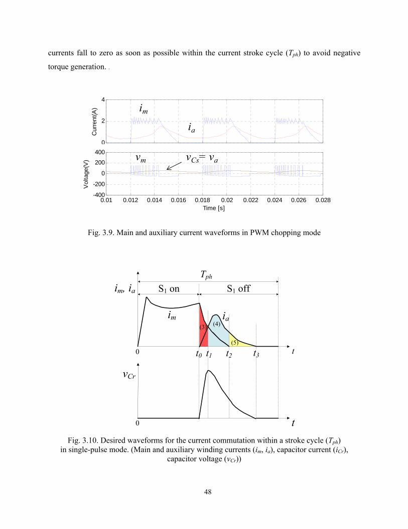
48
currents fall to zero as soon as possible within the current stroke cycle (Tph) to avoid negative
torque generation. .
Fig. 3.9. Main and auxiliary current waveforms in PWM chopping mode
Fig. 3.10. Desired waveforms for the current commutation within a stroke cycle (Tph)
in single-pulse mode. (Main and auxiliary winding currents (im, ia), capacitor current (iCr), capacitor voltage (vCr))
0.01 0.012 0.014 0.016 0.018 0.02 0.022 0.024 0.026 0.028-400
-200
0
200
400
Time [s]
Vol
tage
(V)
0
2
4C
urre
nt(A
) im
ia
vm vCs= va
(4)
(5)
(3)
t
t
Tph
S1 on S1 off
im
im, ia
vCr
0
0
ia
t2 t3t1t0

49
3.5.2 Design Consideration for Optimal Commutation
The commutation time is highly dependent on the parameters (resistance and inductance)
of both main and auxiliary windings as well as the size of Cr. Assuming that the main phase is
optimally designed for the machine’s power specification, the key design parameters are then the
size of Cr and the resistance and inductance of the auxiliary winding, which are determined
mainly by the number of turns on a given machine structure. The calculation of the commutation
time is as follows. The voltage equation of an SRM phase is expressed as
dtdiLiR
dtdiLi
ddLR
dtdi
iR
didRv
eq
r
r
s
+=
+⎟⎠⎞
⎜⎝⎛ +≅
∂∂
+∂∂
+=
+=
θω
ωθλλ
λ
(3.14)
where v, i, R, λ, L, ωr, and θr are phase voltage, phase current, winding resistance, phase flux
linkage, phase self-inductance, rotor speed, and rotor position respectively. The equivalent
resistance of winding (Req) consists of the winding resistance and the constant associated with
the induced back-EMF of the motor winding at constant speed. Note that the phase flux linkage,
λ = L(θ,i)i is a nonlinear function of the phase current and rotor position. During commutation,
the converter can be considered as an RLC circuit with the initial conditions. Therefore, the
system equations for the equivalent RLC circuit are given by
Crm
eqmmeqm vdt
diLiR −=+ (3.15)
Cra
aaeqa vdtdiLiR −=+ (3.16)
amCr
r iidt
dvC −= (3.17)

50
where Reqm and Reqa are the equivalent resistances for main and auxiliary windings,
respectively, and Lm and La are the self-inductances of the main and auxiliary windings,
respectively. The required commutation times (t1, t2, t3) as well as the peak voltage rise of Cr can
be obtained by solving (3.15), (3.16), and (3.17) for im(t), ia(t), and vCr(t). However, solving the
three simultaneous differential equations for an exact expression of im(t) is quite cumbersome.
Therefore, by examining the piecewise waveforms in Fig.3.10 with an assumption that im ≈ iCr
during the initial capacitor charging period, (3.15) can be rewritten as
01=++ ∫ dti
CdtdiLiR m
r
mmmeqm (3.18)
Then, the main winding current is derived as
teIL
VteIti tm
m
Ctmm β
βα
ββ αα sincos)( 00
0−−
⎟⎟⎠
⎞⎜⎜⎝
⎛−+= (3.19)
where
m
eqm
LR2
=α
(3.20)
2
21
⎟⎟⎠
⎞⎜⎜⎝
⎛−=
m
eqm
rm LR
CLβ (3.21)
Im0 is the initial current in the main winding at the beginning of commutation (t=to). During mode
3 region, the equation for the equivalent circuit between t2 and t3 can be expressed as
010 =+++ ∫ Ca
r
aaaeqa Vdti
CdtdiLiR (3.22)
Then, the auxiliary winding current is derived as

51
teIL
VteIti ta
a
Ctaa β
βα
ββ αα sincos)( 00
0−−
⎟⎟⎠
⎞⎜⎜⎝
⎛−+= (3.23)
where
a
eqa
LR2
=α (3.24)
2
21
⎟⎟⎠
⎞⎜⎜⎝
⎛−=
a
eqa
ra LR
CLβ
(3.25)
Ia0 is the initial current in the auxiliary winding at the beginning of commutation (t = t2). The
current commutation time tc for each winding current is obtained by solving (3.19) and (3.23)
using the conditions that im(tc)= 0 and ia(tc) = 0:
⎟⎟⎠
⎞⎜⎜⎝
⎛⎟⎟⎠
⎞⎜⎜⎝
⎛−−= −
βα
βββπ 00
01tan1 a
a
Cac
IL
VIt (3.26)
An approximate equation for Cr voltage is also obtained by solving (3.15), (3.16), and (3.17) for
vCr(t):
⎭⎬⎫
⎩⎨⎧
⎟⎟⎠
⎞⎜⎜⎝
⎛+−
+−++
= −− teIteC
Itv tmt
r
mCr β
βαγαβ
ββαγβα αα sincos1
)()( 22
022
0 (3.27)
where
m
eqm
aeqar
eqaeqm
LR
LRCRR
−+
=α (3.28)
m
eqm
aeqas
eqaeqmsam
aeqas
eqaeqm
LR
LRCRRCLL
LRCRR
−⎟⎟⎠
⎞⎜⎜⎝
⎛ +−
+=
2
2β (3.29)
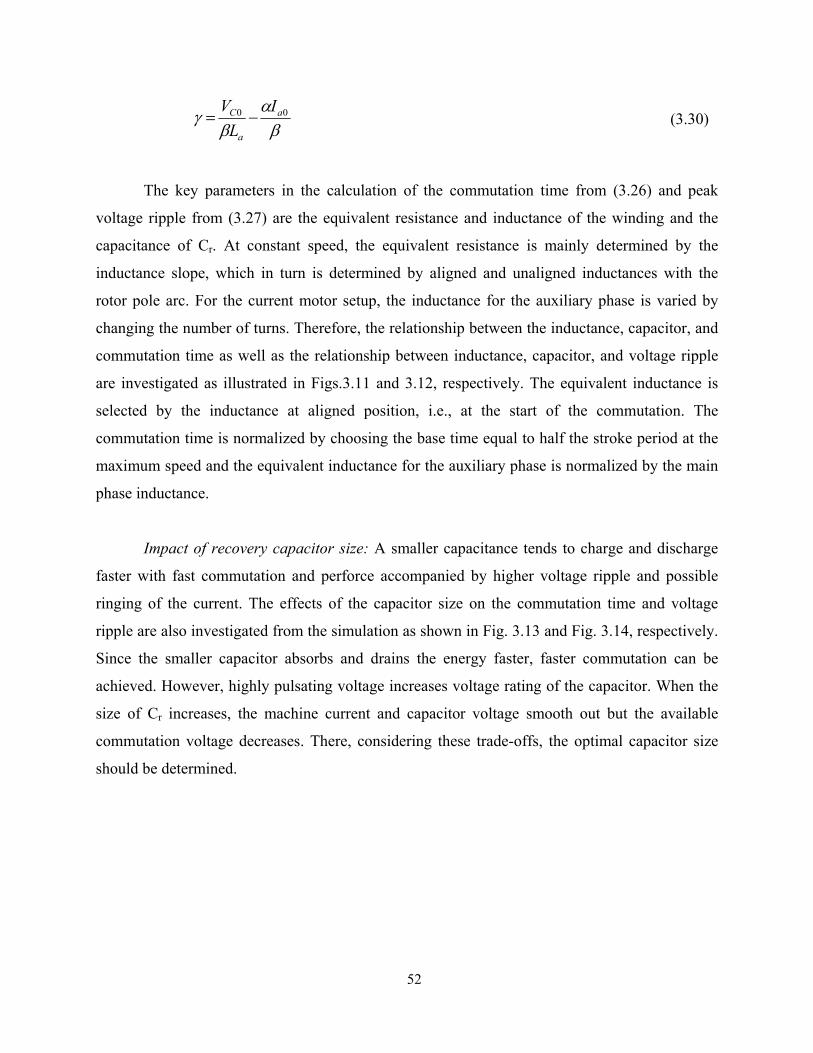
52
βα
βγ 00 a
a
C IL
V−= (3.30)
The key parameters in the calculation of the commutation time from (3.26) and peak
voltage ripple from (3.27) are the equivalent resistance and inductance of the winding and the
capacitance of Cr. At constant speed, the equivalent resistance is mainly determined by the
inductance slope, which in turn is determined by aligned and unaligned inductances with the
rotor pole arc. For the current motor setup, the inductance for the auxiliary phase is varied by
changing the number of turns. Therefore, the relationship between the inductance, capacitor, and
commutation time as well as the relationship between inductance, capacitor, and voltage ripple
are investigated as illustrated in Figs.3.11 and 3.12, respectively. The equivalent inductance is
selected by the inductance at aligned position, i.e., at the start of the commutation. The
commutation time is normalized by choosing the base time equal to half the stroke period at the
maximum speed and the equivalent inductance for the auxiliary phase is normalized by the main
phase inductance.
Impact of recovery capacitor size: A smaller capacitance tends to charge and discharge
faster with fast commutation and perforce accompanied by higher voltage ripple and possible
ringing of the current. The effects of the capacitor size on the commutation time and voltage
ripple are also investigated from the simulation as shown in Fig. 3.13 and Fig. 3.14, respectively.
Since the smaller capacitor absorbs and drains the energy faster, faster commutation can be
achieved. However, highly pulsating voltage increases voltage rating of the capacitor. When the
size of Cr increases, the machine current and capacitor voltage smooth out but the available
commutation voltage decreases. There, considering these trade-offs, the optimal capacitor size
should be determined.

53
Fig. 3.11. Commutation time vs. capacitance vs. inductance
Fig. 3.12. Voltages ripple vs. capacitance vs. inductance.
Com
mut
atio
n tim
e (p
.u)
Equivalent inductance (p.u)0 0.2 0.4 0.6 0.8 1 1.2 1.4 1.6 1.8 2 2.2
0
0.5
1
1.5
2
2.5
Cs = 10uF
Cs = 6.8uF
Cs = 4.7uF
Cs = 3.3uF
Cs = 2.2uF
Volta
ge R
ippl
e (p
.u)
Equivalent inductance (p.u)0 0.2 0.4 0.6 0.8 1 1.2 1.4 1.6 1.8 2 2.2
0
0.5
1
1.5
2
2.5
3
3.5
4
Cs = 2.2uF
Cs = 3.3uF
Cs = 4.7uF
Cs = 6.8uF
Cs = 10uF
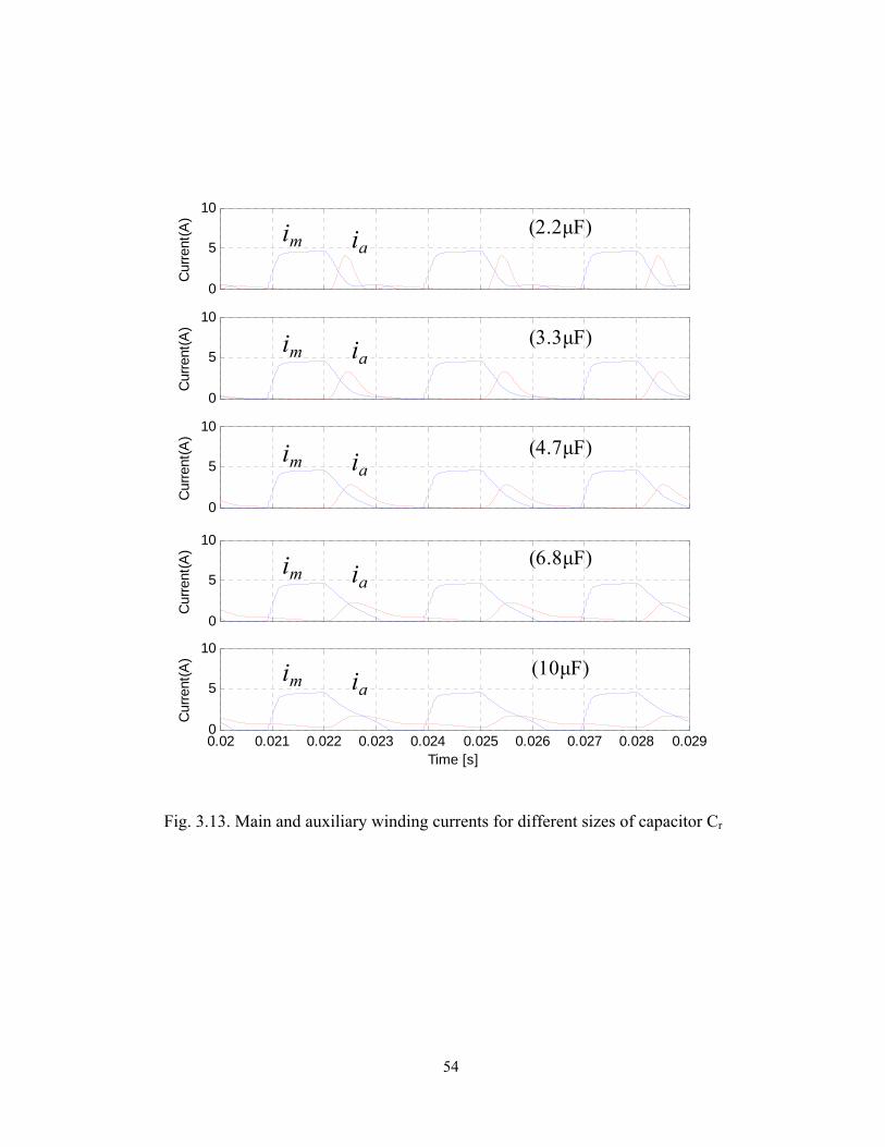
54
Fig. 3.13. Main and auxiliary winding currents for different sizes of capacitor Cr
0.02 0.021 0.022 0.023 0.024 0.025 0.026 0.027 0.028 0.0290
5
10
Time [s]
Cur
rent
(A)
0
5
10
Cur
rent
(A)
0
5
10
Cur
rent
(A)
0
5
10
Cur
rent
(A)
0
5
10
Cur
rent
(A)
im ia
im ia
im ia
im ia
im ia
(3.3μF)
(4.7μF)
(6.8μF)
(10μF)
(2.2μF)

55
Fig. 3.14. Voltages across the main winding, auxiliary winding, and the capacitor Cr
for different size of Cr.
0.02 0.021 0.022 0.023 0.024 0.025 0.026 0.027 0.028 0.029-400-200
0200400
Time [s]
Vol
tage
(V)
-400-200
0200400
Vol
tage
(V)
-400-200
0200400
Vol
tage
(V)
-400-200
0200400
Vol
tage
(V)
-400-200
0200400
Vol
tage
(V) (3.3μF)
(4.7μF)
(6.8μF)
(10μF)
(2.2μF)
vm vCr= va
vm vCr= va
vCr= va
vm vCr= va
vm vCr= va
vm

56
3.6 Comparison of the Proposed Converter With Other Converters
The comparison of the new single-switch converter with the original single-switch
converter, the conventional asymmetric bridge converter for driving a single-phase machine, and
the full-wave bridge inverter for a three-phase ac machine is summarized in Table 3.2. The
comparison is made in terms of the component count, device ratings, and losses to provide a
clear demarcation from the original single-switch drive system and the prevalent three-phase
inverter-based ac system to assess the merits and demerits of the new drive system. For safety
operation, the power switches and diodes are chosen based on their peak and rms current and
voltage ratings. Although the considered motor has two phases, it functions as a single-phase
motor, as most of the torque is produced from the main phase. Hence, the current ratings are the
same as the single-phase motor with the asymmetric converter. However, the switch voltage
rating of the proposed converter is larger than that of the asymmetric converter.
Table 3.2 Comparison of the new converter with other converters
Criteria Full-wave Inverter
Asymmetric Bridge
Original Converter
New Converter
No. of power switches 6 2 1 1 No. of diodes 6 2 1 1
No. of gate drives 6 2 1 1 No. of power supplies for isolated gate drivers (min) 4 2 1 1
Switch voltage rating (min) Vdc Vdc 2Vdc 2Vdc Switch current rating (peak) Ip Ip Ip Ip
Switch current rating (rms)
3Ip 2/Ip
2Ip 2Ip
Converter VA rating (peak) 6VdcIp 2VdcIp 2VdcIp 2VdcIp
Switch conduction losses 2dsIp 2dsIp dsIp dsIp
Diode conduction losses 2(1-ds)I p 2(1-ds)I p (1-ds)I p (1-ds)Ip
Recovery capacitor rating N/A N/A 2.5Vdc 1.5Vdc Heat sink size (p.u) 2 1 0.5 0.5
Note: Ip is the peak rated motor phase current and ds is the switch duty ratio.

57
Although the asymmetric converter is known for its high performance, high cost is its
major disadvantage. Among the advantages of the proposed converter compared to asymmetric
bridge converters are less switching devices hence less driving circuits and less conduction
losses. When compared to the original single-switch converter, the new converter has less
voltage rating for the recovery capacitor. Regardless of their superior performance, the highest
parts count and cost are the major deterrent for the widely-used standard inverter-fed ac drives to
be embraced into the target low cost applications. The selection of power semiconductor devices
including controllable switches and freewheeling diodes takes an important place in designing a
converter. The devices are carefully selected based on several factors but mainly considering a
trade-off among their power handling capability, transient characteristics, and cost.
3.7 Drive System Control
3.7.1 Self-starting
At standstill, when S1 is turned on for a preset period of time to induce a large current
pulse in the main phase winding. This current, along with the current through the auxiliary phase
winding when S1 is turned off, results in torque production and causes the rotor to move. Note
that the number and period of the applied starting pulses are predetermined based on required
starting torque.
3.7.2 Four-quadrant Operation
Significant features peculiar to this converter are limited direct current control of the
main phase and its heavy dependence on the auxiliary phase winding and auxiliary capacitor
state. Likewise, the auxiliary winding current control is dependent on the duty cycle of the
controllable switch, motor speed and load, and state of the auxiliary capacitor. These constraints
have to be managed very tightly in order to implement a four-quadrant variable-speed operation
in this motor drive.
The disadvantages of this drive are: (i) At the time of starting, there is no directional
control but once it is started, the directional and speed control are achieved which is not very
different from many microwave oven drive systems. (ii) Torque ripple free operation is not
feasible with this drive as it functions mostly as a single phase SRM drive system. But this drive

58
has many suitable applications in blenders, hair dryers, vacuum cleaners and other high volume
products that are immensely cost sensitive.
3.7.3 Position Sensorless Operation
Further cost saving of the drive system can be achieved by employing the operation
without a position sensor, hence making the proposed drive system even more attractive to
highly cost-sensitive applications. A large variety of control algorithms for rotor position
sensorless operation have been published so far and selection of a proper scheme is primarily
dependent on the applications and the drive cost. A novel simple position sensorless control
scheme is proposed and implemented on the single-switch converter. This will be discussed in
detail in Chapter 6.
3.8 Dynamic Simulation
To validate the operation principle and analysis of the proposed drive system discussed in
the previous sections, dynamic simulation was performed based on the analytic model derived in
Section II. The nonlinear magnetic and torque characteristics of the machine were obtained from
finite element analysis. The simulation results are given in Fig. 3.15. The waveforms depicted in
Fig.3.15 include the currents of the main and auxiliary windings, voltages across the main and
auxiliary windings, voltage across the capacitor Cr, and the electromagnetic torque. The motor is
running at its rated speed of 5000 r/min supplied from the rectified single-phase ac main
(120Vrms). As shown in Fig.3.15, the commutation of both main and auxiliary winding currents
is achieved effectively without generating a negative torque for a positive load torque.
The proposed drive system shows good commutation of main and auxiliary currents
unlike the previous system where both main and auxiliary currents are continuous as the current
command increases. In single-pulse operation, it is seen that no significant negative torque by the
auxiliary current maximizing the system efficiency.

59
Fig. 3.15. Simulated waveforms for the drive system running at 5000r/min with the 3.3μF
recovery capacitor
3.9 Experimental Verification The prototype single-controllable converter for experiments is shown in Fig. 3.16. The
main converter board has a compact 5”x3” footprint that includes the power stage, gate drive,
analog signal interface, and logic power supply. A DSP controller, TMS320F2808 has been
employed to implement the drive control algorithm. The speed and position are estimated using
two hall-effect sensors mounted on the each of two adjacent stator poles. Device control is
accomplished with an ezDSP evaluation board with a TI C2000F2808 microcontroller. The
MCU is a 32-bit fixed point controller with 100MHz clock and dsp type MAC operations.
Although the F28x series are general purpose chips, they are especially designed for use in high
performance motor controllers. Built-in peripherals include a highly configurable set of 16
PWMs and 6 high resolution PWMS, 16 12-bit ADCs, 3 32-bit CPU timers, 6 32-bit timers and 2
quadrature encoder interfaces. Code development was composed in C++ with the Code
Composer StudioTM IDE and processor programming was enabled by the JTAG-Jet Tms
0
5
10
Cur
rent
(A)
-400-200
0200400
Vol
tage
(V)
0
200
400
Vol
tage
(V)
0.01 0.011 0.012 0.013 0.014 0.015 0.016 0.017 0.018 0.019-1
0
1
Time(s)
Torq
ue(N
-m)
imia
vm
vCr
va
Te avg.Te

60
emulator. Precompiled header files and libraries from the TI site were used to configure and
interface with peripherals, particularly the ADC, PWM and quadrature encoder. Fig. 3.17 shows
the prototype machine utilized for experiments. The minimization of component parts is obvious
for this machine construction and that is an asset in applications.
Experimental testing conducted to validate the performance of the proposed drive system
are described as follows. The execution of the self-starting algorithm is shown in Fig. 3.18. At
standstill, S1 is turned on for a preset period of time to induce a large current pulse in the main
phase winding. This current, along with the current through the auxiliary phase winding when S1
is turned off, results in torque production causing the rotor to move. Note that the number and
period of the applied starting pulses are predetermined based on required starting torque to
achieve reliable starting at any rotor position. Once the motor starts, the controller executes the
normal commutation algorithm for the main phase and the motor is driven to the desired speed.
Only during the short period of initial acceleration, the PWM chopping mode is employed and
then the control transitions to the single-pulse mode, reaching its rated speed quickly. The
commutation angle control for the main phase is based on the optimized turn-on and turn-off
angles for different speed ranges, estimated from dynamic simulations. Fig. 3.19 shows the
measured waveforms of the main and auxiliary winding currents as well as the recovery
capacitor voltage for the drive system operating at its base speed of 5000 r/min. The optimal size
of the recovery capacitor for the prototype drive was selected based on the analytic estimation
and the simulation results discussed in Section 3.5. It can be seen that the measured waveforms
in Fig. 319 are very similar to those from the simulation in Fig. 3.15, i.e., the commutation of the
main phase is achieved successfully through the auxiliary winding and recovery capacitor, which
correlates well with the simulation results. Unlike the continuous conduction in PWM operation
shown in Fig.3.9, the desirable commutation of the auxiliary winding in single-pulse mode is
also achieved.
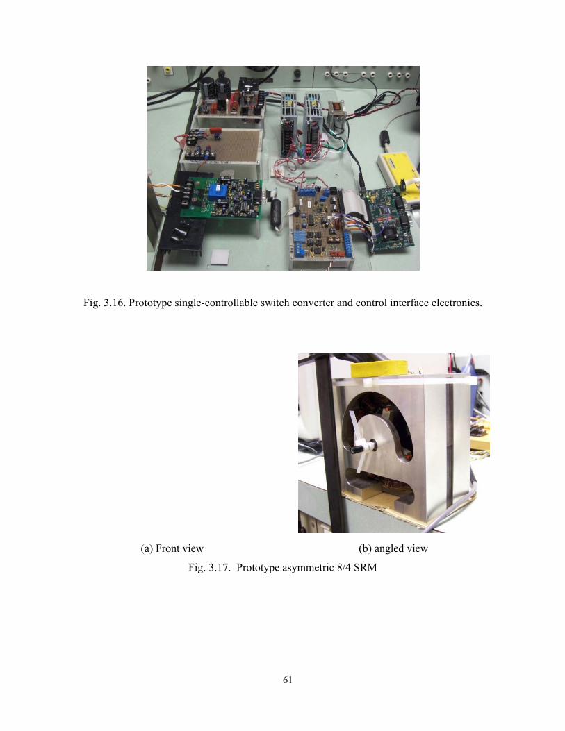
61
Fig. 3.16. Prototype single-controllable switch converter and control interface electronics.
(a) Front view (b) angled view
Fig. 3.17. Prototype asymmetric 8/4 SRM

62
Fig. 3.18. Execution of self-starting of the motor from standstill
Fig. 3.19. Measured waveforms: main and auxiliary winding currents, recovery capacitor voltage
(Cr =3.3μF) when the motor is running at 5000r/min
Time (0.1s/div)
Starting pulse applied
Commutation starts here.
Hall sensor 1(1V/div)
Main phase current
(2A/div)
Hall sensor 2(1V/div)
Gate signal(20V/div)
Aux. phasecurrent
(5V/div)
Time (1ms/div)
Main phasecurrent
(5A/div)
Capacitor CrVoltage
(100V/div)

63
Acoustic noise is a serious concern in SRM drives and particularly so in the single phase
category because of the inherent discontinuous torque generation. The least noise is produced by
the SRM driven with asymmetric converter as it has tremendous control latitude. In order to
ascertain the control quality offered by the new converter, it is important to compare the noise
performance with that of the asymmetric converter based single phase SRM drive. The acoustic
noise measurement results on the laboratory prototype are given in Table 3.3. In order to
accurately measure the audible noise caused by vibrations in electrical machines, it usually is
made in an anechoic chamber after calibrating the measuring equipments and measuring sound
pressure at several points. However, an anechoic chamber is not available in the normal
laboratory environment and, therefore, measurements can be made in an ordinary large room
after measuring the ambient noise. The measurement was conducted in a laboratory with
49.5dBA ambient noise. The new converter produces slightly less noise level than the original
converter. At 2000r/min with PWM control, the both single-switch converters generate more
noise than the asymmetric converter due to the continuous conduction in auxiliary winding
causing negative torque. In the single-pulse mode (5000r/min), however, the single-switch
converters generate the noise level comparable to that of the asymmetric converter-based drive
and note that this is the intended control strategy for targeted applications.
Table 3.3. Measured acoustic noise
Asymmetric converter
Original converter New converter
PWM mode 56.5 60.7 60.2
Single-pulse mode 65.4 66.1 65.8
Note: The unit is dB and the ambient noise is 49.2dBA.
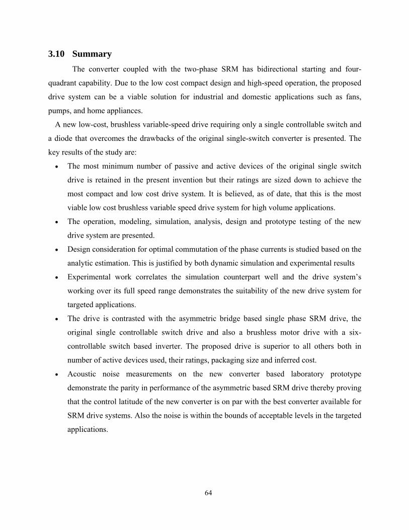
64
3.10 Summary The converter coupled with the two-phase SRM has bidirectional starting and four-
quadrant capability. Due to the low cost compact design and high-speed operation, the proposed
drive system can be a viable solution for industrial and domestic applications such as fans,
pumps, and home appliances.
A new low-cost, brushless variable-speed drive requiring only a single controllable switch and
a diode that overcomes the drawbacks of the original single-switch converter is presented. The
key results of the study are:
• The most minimum number of passive and active devices of the original single switch
drive is retained in the present invention but their ratings are sized down to achieve the
most compact and low cost drive system. It is believed, as of date, that this is the most
viable low cost brushless variable speed drive system for high volume applications.
• The operation, modeling, simulation, analysis, design and prototype testing of the new
drive system are presented.
• Design consideration for optimal commutation of the phase currents is studied based on the
analytic estimation. This is justified by both dynamic simulation and experimental results
• Experimental work correlates the simulation counterpart well and the drive system’s
working over its full speed range demonstrates the suitability of the new drive system for
targeted applications.
• The drive is contrasted with the asymmetric bridge based single phase SRM drive, the
original single controllable switch drive and also a brushless motor drive with a six-
controllable switch based inverter. The proposed drive is superior to all others both in
number of active devices used, their ratings, packaging size and inferred cost.
• Acoustic noise measurements on the new converter based laboratory prototype
demonstrate the parity in performance of the asymmetric based SRM drive thereby proving
that the control latitude of the new converter is on par with the best converter available for
SRM drive systems. Also the noise is within the bounds of acceptable levels in the targeted
applications.

65
Chapter 4
Proposed Drive System 2:
Two-Controllable-Switch-Based SRM Drive
4.1 Introduction Although the single-controllable-switch-based SRM drive presented in the previous
chapter can be a strong candidate for low cost high volume applications, precise control of the
main phase winding current is not possible at all levels of current and lack of control of the
auxiliary phase winding current results in increased torque ripple and reduced system efficiency.
Therefore, a new two-switch converter [33] that improves performance while still preserving the
advantages of the single-switch drive is presented and studied in detail in this chapter.
The proposed power converter employs a single-switch-per-phase configuration, hence
requiring only two controllable switches in total to drive a two-phase SRM. Therefore, the
converter is still cost-effective compared to the conventional asymmetric converter which
requires a total of four controllable switches to drive a two-phase SRM.
The converter is unique in that it has two capacitors for energization of each phase. The
primary capacitor, C1 functions mainly as a stiff voltage source to energize phase A (main
winding), and the main phase winding is used as an energy storage for the secondary capacitor,
C2 which, in turn, is used for phase B (auxiliary winding) energization as well as energy
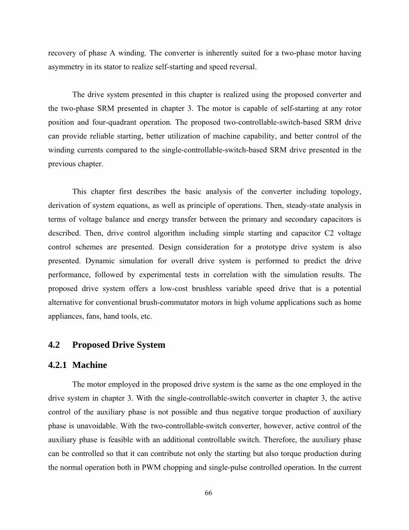
66
recovery of phase A winding. The converter is inherently suited for a two-phase motor having
asymmetry in its stator to realize self-starting and speed reversal.
The drive system presented in this chapter is realized using the proposed converter and
the two-phase SRM presented in chapter 3. The motor is capable of self-starting at any rotor
position and four-quadrant operation. The proposed two-controllable-switch-based SRM drive
can provide reliable starting, better utilization of machine capability, and better control of the
winding currents compared to the single-controllable-switch-based SRM drive presented in the
previous chapter.
This chapter first describes the basic analysis of the converter including topology,
derivation of system equations, as well as principle of operations. Then, steady-state analysis in
terms of voltage balance and energy transfer between the primary and secondary capacitors is
described. Then, drive control algorithm including simple starting and capacitor C2 voltage
control schemes are presented. Design consideration for a prototype drive system is also
presented. Dynamic simulation for overall drive system is performed to predict the drive
performance, followed by experimental tests in correlation with the simulation results. The
proposed drive system offers a low-cost brushless variable speed drive that is a potential
alternative for conventional brush-commutator motors in high volume applications such as home
appliances, fans, hand tools, etc.
4.2 Proposed Drive System
4.2.1 Machine
The motor employed in the proposed drive system is the same as the one employed in the
drive system in chapter 3. With the single-controllable-switch converter in chapter 3, the active
control of the auxiliary phase is not possible and thus negative torque production of auxiliary
phase is unavoidable. With the two-controllable-switch converter, however, active control of the
auxiliary phase is feasible with an additional controllable switch. Therefore, the auxiliary phase
can be controlled so that it can contribute not only the starting but also torque production during
the normal operation both in PWM chopping and single-pulse controlled operation. In the current

67
experimental system, only one set of diametrically opposite auxiliary windings are utilized. This
reduces the machine into an equivalent of a two phase motor. Additional information on
magnetization characteristics and performance is presented in chapter 2.
4.2.2 Power Converter
The topology of the novel power converter is shown in Fig. 4.1. The converter has two
capacitors contributing to each phase’s magnetization, i.e. the primary capacitor, C1 for phase A
(main winding) and the secondary capacitor, C2 for phase B (auxiliary winding). During
demagnetization of the phase windings, capacitors C1 and C2 are charged by energy from the
complementary phase. In this regard, the converter has a similarity with the split dc source
converter for a two-phase SRM. The key features of the proposed converter can be deduced by
observations and they are:
1) The converter has a low cost single-switch-per-phase (SSPP) configuration. Therefore,
packaging of drive electronics can be compact resulting in smaller heat sink, lower
number of gate drives, and lower number of isolated power supplies for gate drives.
2) Having only one switch per phase yields only one switch voltage drop per phase. This
makes the converter suitable for low supply voltage applications.
3) There is no freewheeling mode available in this converter. Only two modes,
magnetization and demagnetization of the machine phase windings are available and they
are realized by switching the transistors T1 and T2.
4) Due to the absence of the freewheeling mode, soft chopping scheme cannot be employed.
Thus, finer control of the current in terms of its ripple may not be feasible.
5) While C1 is a stiff voltage source fed by the rectified AC main, C2 is a dependent voltage
source fed only by demagnetization energy from phase A.
6) Although C2 is dependent on phase A excitation, with careful selection of this capacitor,
the average voltage and ripple of C2 can be maintained within an acceptable range over
the entire speed range. The unequal voltages of C1 and C2 do not affect significantly the
operation of the drive system.
7) The converter is inherently suited for two-phase SRMs having asymmetric stator phases
to realize self-starting as well as speed reversal.

68
8) By directly controlling the auxiliary phase winding (phase B) current, the negative torque
affecting efficiency and noise when the drive system is realized with the single-switch
converter can be improved. Hence, the drive can achieve better utilization of the
electromagnetic capability of the motor.
Fig. 4.1. Proposed two-controllable-switch converter
4.3 Derivation of System Equations and Principle of Operation
In every switching period, each phase encounters two main modes: magnetization and
demagnetization. Hence, four main modes in addition to two auxiliary modes are available as
illustrated from Figs. 4.2 through 4.7. Each mode of operation is described with corresponding
voltage and current equations, respectively. Note that each phase winding has different number
of turns and thus different resistance and inductance.
Mode A-1 : Phase A Magnetization
When T1 is turned on, the dc link voltage, VC1 is applied to phase A winding. Current
flows through C1 and T1 thus magnetizing the phase A winding. The voltage and current
equation equations for this mode are given by

69
dtdiLi
ddLR
ddLi
dtdiLiRVv
aaar
aa
ra
aa
aaaCa
+⎟⎠⎞
⎜⎝⎛ +=
++==
ωθ
ωθ1
(4.1)
( )aa t
aeq
Ctaa e
RVeIti ττ −− −+= 1)(
_
11 (4.2)
where
raaaeq ddLRR ωθ )(_ += (4.3)
aeqaa RL _=τ (4.4)
Ra is phase A winding resistance, La is phase A’s self-inductance, ωr is the rotor speed, and Ia1 is
the initial current in phase A for this mode.
Mode A-2 : Phase A Demagnetization
When T1 is turned off, negative voltage, –VC2 is applied to phase A winding. The current
continues to flow but through a different path, phase A, C2, and D1 resulting in demagnetization
of phase A, hence charging C2. The voltage and current equations for this mode are given by
dtdiLi
ddLR
ddLi
dtdiLiRVv
aaar
aa
ra
aa
aaaCa
+⎟⎠⎞
⎜⎝⎛ +=
++=−=
ωθ
ωθ2
(4.5)
( )aa t
aeq
Ctaa e
RVeIti ττ −− −−= 1)(
_
12 (4.6)
where Ia2 is the initial current in phase A current for this mode.

70
Fig. 4.2 Mode A-1 (T1: on, T2: off, D1: off, D2: off)
Fig. 4.3 Mode A-2 (T1: off, T2: off, D1: on, D2: off)
Mode B-1: Phase B Magnetization
When T2 is turned on, the capacitor C2 voltage VC2 is applied across phase B. Current
circulates through C2, phase B, and T2 thereby supplying energy to magnetize the phase B
winding. The voltage and current equations for this mode can be derived similarly to those of
phase A and they are

71
dtdiLi
ddLR
ddLi
dtdiLiRVv
bbbr
bb
rb
bb
bbbCb
+⎟⎠⎞
⎜⎝⎛ +=
++==
ωθ
ωθ2
(4.7)
( )bb t
beq
Ctbb e
RVeIti ττ −− −+= 1)(
_
21 (4.8)
where
rbbbeq ddLRR ωθ )(_ += (4.9)
beqbb RL _=τ
(4.10)
where Rb is phase B winding resistance, Lb is the phase B self-inductance, and Ib1 is the initial
current of phase B winding, respectively.
Mode B-2 : Phase B Demagnetization
When T2 is turned off, the current continues to flow but through phase B, D2, and C1.
The voltage applied to phase B winding is -VC2, and phase B begins to demagnetize. The voltage
and current equations for this mode are given by
dtdiLi
ddLR
ddLi
dtdiLiRVv
bbbr
bb
rb
bb
bbbCb
+⎟⎠⎞
⎜⎝⎛ +=
++=−=
ωθ
ωθ1
(4.11)
( )ba t
beq
Ctbb e
RVeIti ττ −− −−= 1)(
_
12 (4.12)
where Ib2 is the initial condition on phase B current for this mode. During the commutation of
each phase current there is a phase current overlaps, i.e. the both phase in Figs.4.6 and 4.7
Although it might be negligible the mutual coupling
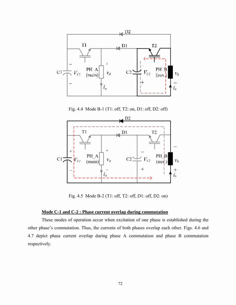
72
Fig. 4.4 Mode B-1 (T1: off, T2: on, D1: off, D2: off)
Fig. 4.5 Mode B-2 (T1: off, T2: off, D1: off, D2: on)
Mode C-1 and C-2 : Phase current overlap during commutation
These modes of operation occur when excitation of one phase is established during the
other phase’s commutation. Thus, the currents of both phases overlap each other. Figs. 4.6 and
4.7 depict phase current overlap during phase A commutation and phase B commutation
respectively.
T1
+
_
C1 C2
T2
_
+ia ib
VC2VC1 va
+
_ +
_vb
PH_A(main)
PH_B(aux.)
D1
D2

73
Fig. 4.6. Mode C-1: Current overlap during the phase A commutation
Fig. 4.7. Mode C-2: Current overlap during the phase B commutation
4.4 Steady State Analysis
4.4.1 Estimation of Capacitor C2 Voltage
The charging of C2 is dependent on the amount of energy recovered from phase A, and
the discharging of C2 is determined by the amount of energy required for phase B excitation.
T1
+
_
C1
D1
C2
T2
_
+
PH_A(main)
PH_B(aux.)
D2
ia ib
VC2VC1 va
+
_vb
+
_
T1
+
_
C1
D1
C2
T2
_
+
PH_A(main)
PH_B(aux.)
D2
ia ib
VC2VC1 va
+
_ +
_

74
Therefore, C2 voltage, VC2 varies with operating conditions and it is difficult to estimate and
control it at the same level as C1 voltage, VC1.
The voltage imbalance between C1 and C2 results in unequal excitation and commutation
for each phase. However, this imbalance does not affect the drive performance significantly due
to the unique machine structure of which the stator phases are asymmetric. Phase B (auxiliary
winding) is much smaller in stator pole size and in winding copper volume compared to the
phase A (main winding), optimized for the cost of the drive system. Phase A contributes to most
of the generated torque, while phase B aids in starting and speed reversal. Therefore, as long as
VC2 can be maintained within a level sufficient to produce self-starting and contribute to
motoring and speed reversal, the voltage imbalance cannot be a hindrance to operation of the
drive since the target applications are not torque ripple sensitive. However, reasonable estimation
of VC2 is important for the proper design and operation of the drive system and it can be
estimated as follows.
The proposed converter can be considered as a buck-boost topology assuming phase A
winding as an energy storage inductor and phase B winding with T2 and D2 as an equivalent
load as shown in Fig. 4.8. However, unlike the conventional dc-dc converter, the machine phase
should be modeled by winding resistance, self-inductance, and induced back-EMF in series in
the motor winding. The equivalent load for phase B can be given by
max,
max,
eq
Lreeqbeq i
vKiRZ b
++=
ω (4.13)
where ieq,max is the maximum current required by phase B, Ke = dLb/dθ, is the back-EMF constant
of phase B, and vLb = Lb(dib/dt) is the inductive voltage drop in phase B winding, respectively. It
is assumed that during steady-state operation all voltages and currents are periodic, and the speed
and back-EMF are constant.
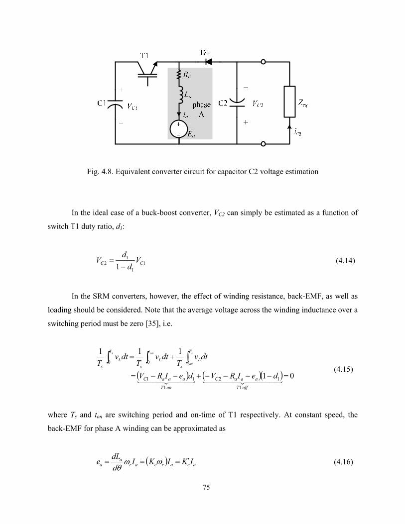
75
Fig. 4.8. Equivalent converter circuit for capacitor C2 voltage estimation
In the ideal case of a buck-boost converter, VC2 can simply be estimated as a function of
switch T1 duty ratio, d1:
11
12 1 CC V
dd
V−
= (4.14)
In the SRM converters, however, the effect of winding resistance, back-EMF, as well as
loading should be considered. Note that the average voltage across the winding inductance over a
switching period must be zero [35], i.e.
( ) ( )( ) 01
111
1
12
1
11
00
=−−−−+−−=
+= ∫∫∫
4444 34444 21444 3444 21offT
aaaC
onT
aaaC
T
t Ls
t
Ls
T
Ls
deIRVdeIRV
dtvT
dtvT
dtvT
s
on
ons
(4.15)
where Ts and ton are switching period and on-time of T1 respectively. At constant speed, the
back-EMF for phase A winding can be approximated as
( ) aeareara
a IKIKIddLe ′=== ωωθ
(4.16)
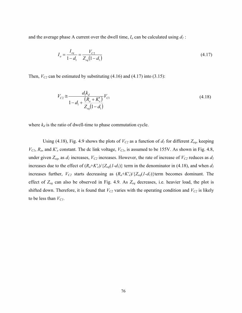
76
and the average phase A current over the dwell time, Ia can be calculated using d1 :
( )1
2
1 11 dZV
dI
Ieq
Ceqa −
=−
= (4.17)
Then, VC2 can be estimated by substituting (4.16) and (4.17) into (3.15):
( )( )
1
11
12
11
C
eq
ea
dC V
dZKRd
kdV
−′+
+−≅ (4.18)
where kd is the ratio of dwell-time to phase commutation cycle.
Using (4.18), Fig. 4.9 shows the plots of VC2 as a function of d1 for different Zeq, keeping
VC1, Ra, and K'e constant. The dc link voltage, VC1, is assumed to be 155V. As shown in Fig. 4.8,
under given Zeq, as d1 increases, VC2 increases. However, the rate of increase of VC2 reduces as d1
increases due to the effect of (Ra+K'e)/Zeq(1-d1) term in the denominator in (4.18), and when d1
increases further, VC2 starts decreasing as (Ra+K'e)/Zeq(1-d1)term becomes dominant. The
effect of Zeq can also be observed in Fig. 4.9. As Zeq decreases, i.e. heavier load, the plot is
shifted down. Therefore, it is found that VC2 varies with the operating condition and VC2 is likely
to be less than VC1.

77
Fig. 4.9. Estimation of C2 voltage as a function of d1 for different Zeq
4.4.2 Power Transfer Between C1 and C2
During the magnetization and demagnetization of the machine windings, power is
transferred between the two capacitors via the phase windings as shown in Figs. 4.10 and 4.11
The converter can be seen as a conventional buck-boost converter in term of power transfer from
C1 to C2 via phase A winding (Fig. 4.10) and from C2 to C1 via phase B winding (Fig. 4.11).
The average power transfer between the capacitors can be calculated using averaging technique
as illustrated in Fig. 4.12. This is important in that from this calculation, we can find the required
power for phase B supplied by C2 and a critical C2 voltage for C2 selection.
0.1 0.2 0.3 0.4 0.5 0.6 0.7 0.8 0.90
20
40
60
80
100
120
140
160
180
50% load75% load100% load
Vol
tage
(V)
T1 duty ratio, d1

78
Fig. 4.10. Power transfer from capacitor C1 to C2 via phase A winding
Fig. 4.11. Power transfer from capacitor C2 to C1 via phase B winding
When T1 is turned on during the motoring region, the phase A winding is magnetized.
Part of the energy from C1 is stored magnetically in phase A winding and part is converted into
mechanical output. The power transferred from capacitor C1 to phase A winding during T1 on-
time interval is given by
raa
aa
CAC
ddLiiL
dtd
vCdtdtp
ωθ22
121)(
22
211_1
+⎟⎠⎞
⎜⎝⎛=
⎟⎠⎞
⎜⎝⎛=
(4.19)

79
The first term in the right-hand side of (4.19) is the rate of energy stored in magnetic field and
the second term is mechanical power. The average power delivered from C1 to phase A can be
calculated by
( ) aCaCTCAC IVdIdVIVP 111111_1 === (4.20)
where IT1 is average switch T1 current, d1 is switching duty ratio of T1, and Ia is average phase A
current during excitation.
When T1is is turned off, stored magnetic energy is partly converted to mechanical output
and partly supplied to capacitor C2. The power transferred from phase A to C2 is
⎟⎠⎞
⎜⎝⎛+=
⎟⎠⎞
⎜⎝⎛=
222
2
22_
21
2
21)(
Craa
aaCA
vCdtd
ddLi
iLdtdtp
ωθ
(4.21)
The average power delivered to C2 can be calculated by
( ) ( ) aCaCDCCA IVdIdVIVP 2112122_ 11 −=−== (4.22)
where ID1 is average diode D1 current. The power transferred from C2 to C1 via phase B
winding can also be calculated similarly to above calculations. From (4.20), minimum power
required by phase B for critical C2 voltage can be calculated.
Likewise, the average power transferred from C2 to phase B can be calculated by
( ) bCbCTCBC IVdIdVIVP 222222_2 === (4.23)
where IT2 is average switch T2 current, d2 is switching duty ratio of T2, and Ib is the average
phase B current during excitation. The power transferred from phase B to C1 can also be
calculated by

80
( ) ( ) bCbCDCCB IVdIdVIVP 1221211_ 11 −=−== (4.24)
where ID2 is the average D2 current.
Fig. 4.12. Operational waveforms for power calculation
4.5 Design Consideration
There are several factors to be considered when choosing power switching devices for the
SRM converter such as drive power level, supply voltage, current rating, cost, etc. The minimum
voltage rating of the power devices is determined by the peak voltage stress applied to the
devices. Assuming capacitor C2 is charged up to dc link voltage level, Vdc, the peak voltage
stress on each switch T1 and T2 at turn-off instant is 2Vdc. Therefore, the minimum voltage
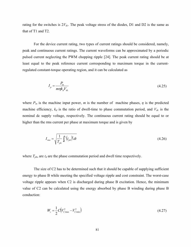
81
rating for the switches is 2Vdc. The peak voltage stress of the diodes, D1 and D2 is the same as
that of T1 and T2.
For the device current rating, two types of current ratings should be considered, namely,
peak and continuous current ratings. The current waveforms can be approximated by a periodic
pulsed current neglecting the PWM chopping ripple [24]. The peak current rating should be at
least equal to the peak reference current corresponding to maximum torque in the current-
regulated constant-torque operating region, and it can be calculated as
dcd
inp Vkm
PIη
= (4.25)
where Pin is the machine input power, m is the number of machine phases, η is the predicted
machine efficiency, kd is the ratio of dwell-time to phase commutation period, and Vdc is the
nominal dc supply voltage, respectively. The continuous current rating should be equal to or
higher than the rms current per phase at maximum torque and is given by
( ) dtiT
I dt
phph
rms ∫=0
21 (4.26)
where Tph, are td are the phase commutation period and dwell time respectively.
The size of C2 has to be determined such that it should be capable of supplying sufficient
energy to phase B while meeting the specified voltage ripple and cost constraint. The worst-case
voltage ripple appears when C2 is discharged during phase B excitation. Hence, the minimum
value of C2 can be calculated using the energy absorbed by phase B winding during phase B
conduction:
( )2min
2max2
1CCc VVCW −= (4.27)

82
( )2min
2max
2
CC
c
VVtPC
−Δ
= (4.28)
where Vmax and Vmim are the maximum and minimum value of the capacitor C2 voltage
considering less than 20% ripple, Pb is power required by phase B, ∆t is the maximum phase B
conduction time.
4.6 Drive Control and Operation
4.6.1 Starting
The voltage of capacitor C2 is zero at standstill. Therefore, first, C2 has to be charged up
to a level that is sufficient for torque production through phase B to facilitate starting. This can
be achieved using a starting scheme similar to the scheme proposed in [31]. Applying a single-
or multiple pulses to phase A winding for a finite time by switching T1 results in torque
production to align the rotor pole with the phase A stator pole. When T1 is turned off, the current
decays through C2 and thus charges it. Note that the duration and number of pulses are
predetermined based on the required starting torque and required value of C2 voltage. Fig. 4.13
shows the initial charging of C2. The dc link voltage, VC1 is 155V. Applying a pulse for a short
period of time impresses current in phase A and charges C2 up to 120V.
After rotor alignment and C2 charging, the controller executes an algorithm for
commutation of each phase in synchronism with rotor position. It is critical to ensure that the
desired direction of rotation is enforced quickly when the self-starting pulse is applied, so that
the rotor does not traverse noticeably over a significant angular distance in the unintended
direction. If the motor starts in the opposite direction to the desired direction, then the controller
quickly reverses the direction to meet the direction requirement. That will involve motion in an
undesirable direction for a short rotor movement and it usually is tolerated in low cost
applications that this power converter is aimed at.

83
Fig. 4.13. Measured waveforms (vC1 : C1 voltage, ia: phase A current, vC1 : C2 voltage) during
initial charging of capacitor C2 by applying a starting pulse.
4.6.2 Drive System Control
Figs. 4.14(a) and (b) show the flowcharts of the control algorithms implemented in the
proposed drive system. The overall drive system control shown in Fig. 4.14(a) is composed of
three main parts: starting, main control loop, and VC2 monitoring. Once the motor starts, the
controller executes the main control loop. The outermost loop is the speed control executed
every 1ms, and the inner control loops are PI current control and phase commutation, which are
executed at 20 kHz. Thus, the motor runs at a predefined speed command. Once the motor starts
running, VC2 begins to decrease from its initially charged value and then reaches a steady-state
value determined by the drive operating point. Although it has been experimentally found that
VC2 settles within an acceptable level in most cases, careful monitoring of VC2 may be required in
such conditions as low dc supply voltage or very low speed operations, where VC2 can be
critically small and furthermore, the waveform of VC2 can be discontinuous. If VC2 becomes too
small, C2 may not be able to supply sufficient energy for phase B excitation. In addition, too
small VC2 means insufficient voltage for demagnetization of phase A; hence, a longer tail current
vC1
ia[2A/div]
[100V/div]
vC2[50V/div]
Starting pulse appliedTime(10ms/div)
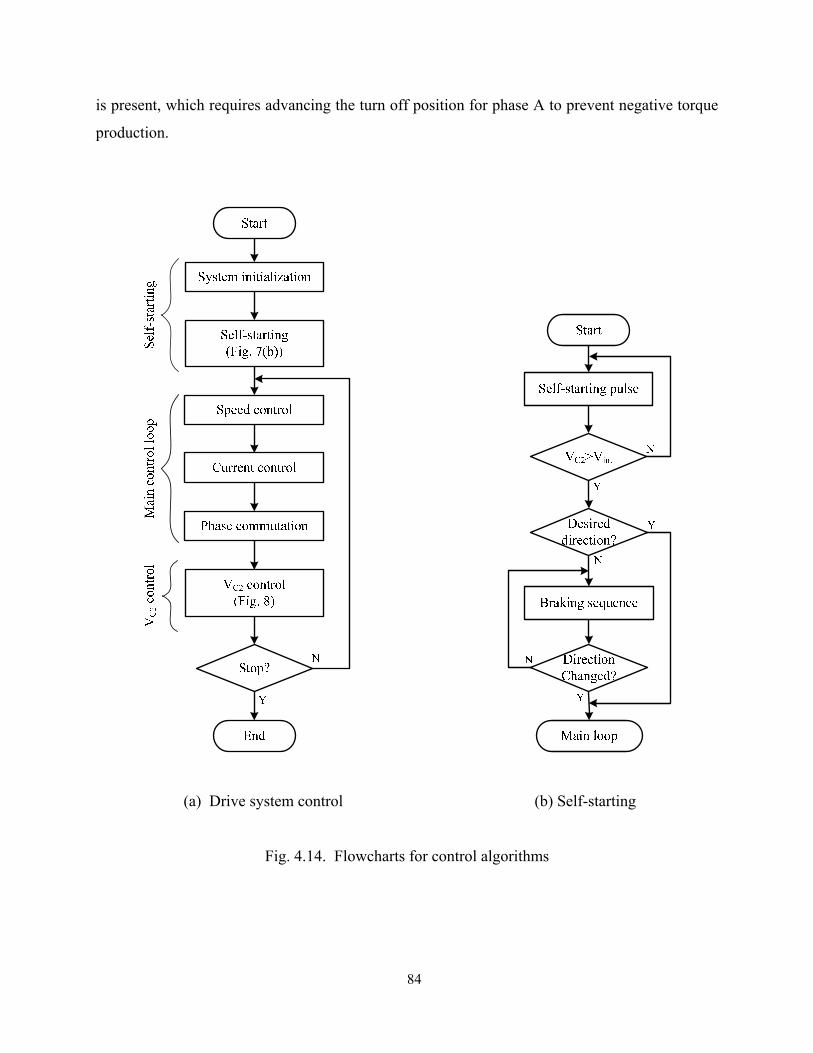
84
is present, which requires advancing the turn off position for phase A to prevent negative torque
production.
(a) Drive system control (b) Self-starting
Fig. 4.14. Flowcharts for control algorithms

85
A simple control scheme can be employed to control VC2 within a desired level. This
scheme is illustrated in Fig. 4.15. When VC2 drops below the predetermined minimum value,
Vk the difference is fed to a PI controller to generate a command signal which is added to or
subtracted from the phase current command signal generated from the speed controller.
Therefore, the final current command depends both on the speed command and VC2 level.
Once VC2 becomes larger than the minimum value, the voltage controller is disabled until
VC2 becomes smaller than Vk again.
Due to the unique machine topology, precise current control in phase B (auxiliary
winding) is not essential in increasing the performance of the drive system, and hence the
drive can be controlled by either single pulse operation or average voltage control with a
fixed PWM chopping. This makes it possible to eliminate the current control of phase B in
low cost applications and to some extent, the same may be applicable for phase A too.
Fig. 4.15. Capcitor C2 voltage control.
4.7 Simulation Verification
The detailed simulation and experimental tests have been made to investigate
performance of the proposed drive system. The nonlinear magnetization and torque
characteristics of the prototype machine are modeled using finite-element analysis (FEA), and
*ai
*bi
2CV
*_a newi
*_b newi
VΔ
0 ( 0)1 ( 0)
VV
Δ <⎧⎨ Δ ≥⎩
kV

86
simulation of the overall drive system including the non-ideal converter modeling and machine
modeling interfaced with FEA has been achieved using software, called “Simplorer”. The rms ac
main voltage is 120V and the capacitance of C1 and C2 is 1000uF. The simulated waveforms of
currents and voltages for each phase running at 2000r/min are shown in Fig. 4.16. Hysteresis
current control has been employed to simulate the drive system. As shown in Fig. 4.16, the dwell
time for phase B is much shorter than phase A due to the unique machine structure of which the
positive motoring region (dL/dθ > 0) for phase B is much smaller than that of phase A. The large
switching ripple in phase B current results from the very small time constant of phase B
windings compared to phase A.
Fig. 4.16. Simulated results: Phase current and voltage waveforms of the
drive system operating at 2000 r/min
Cur
rent
[A]
0
2
4
0
2
4
0.66 0.662 0.664 0.666 0.668 0.67 0.672 0.674 0.676-200
0
200
-200
0
200
Vol
tage
[V
]C
urre
nt [A
]V
olta
ge [
V]
ia
ib
vb
va
Time [s]

87
4.8 Experimental Results
The prototype two-switch converter employed in the proposed drive system is shown in
Fig. 4.17 and the experimental configuration to test the proposed drive system is shown in Fig.
4.18. The dc link voltage, VC1 is approximately 155V from the rectified ac main. The power
switching devices for the converter are realized with 600V-15A ultra-fast IGBTs and fast-
recovery diodes. Capacitors C1 and C2 are 1000uF electrolytic capacitors with a voltage rating
of 450VDC. TMS320F2808 from Texas Instruments has been utilized to implement the drive
control algorithms. Two Hall-effect sensors to estimate the rotor position and speed are mounted
on two stator poles: one on a main pole, the other on an adjacent auxiliary pole. PWM based PI
current and speed control scheme is employed. The sampling frequency is 20 kHz and speed
control loop is executed every 1ms. Fig. 4.19 shows the measured waveforms of phase currents
and voltages which are comparable to the simulated waveforms in Fig. 4.16. Waveforms at two
operating speeds at 2000 r/min (Fig. 4.19) and at 4500 r/min (Fig. 4.20) were measured.
Fig. 4.17. Prototype two-switch-based buckboost converter
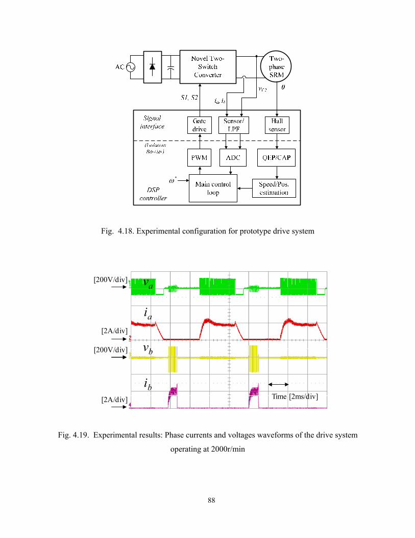
88
Fig. 4.18. Experimental configuration for prototype drive system
Fig. 4.19. Experimental results: Phase currents and voltages waveforms of the drive system
operating at 2000r/min
*ω
Time [2ms/div]
va
ia
vb
ib[2A/div]
[200V/div]
[2A/div]
[200V/div]

89
Fig. 4.20. Experimental results: Phase currents and voltages waveforms of the drive system
operating at 4500r/min
4.9 Summary
A low cost two-switch based converter for a two-phase SRM has been proposed. The
proposed converter drive system has been analyzed, designed, and implemented in a prototype
form. The steady-state analysis of the converter has been made including: 1) capacitors voltage
imbalance, 2) power transfer between C1 and C2, 3) estimation of C2 voltage. Simple starting
and C2 voltage control has been implemented, and the steady-state and dynamic performance of
the drive system have been experimentally demonstrated. The proposed converter drive system
has following advantages and disadvantages:
Advantages
1) The proposed converter has a very low cost single-switch-per-phase configuration
that leads to more compact packaging and cost reduction than conventional two-
switch-per-phase converters.
2) Having only one switch per phase yields only one switch voltage drop per phase. This
makes the converter suitable for low supply voltage applications.
3) The converter is inherently suited for two-phase SRMs having asymmetry in their
Time[1ms/div]
va
ia
vb
ib[2A/div]
[200V/div]
[4A/div]
[200V/div]

90
stator phases for self-starting and speed reversal purpose.
4) Compared to the single-switch converter, the proposed converter provides better
control of phase currents. Thus, large torque ripple and reduced efficiency due to lack
of auxiliary phase control in the single-switch drive can be improved.
Disadvantages
1) Fast current commutation of phase A may be limited by since the capacitor C2
voltage varies with the operation condition, and is likely to be less than VC1.
2) Lower average torque is available than two-phase SRM drives with conventional two-
switch-per-phase converter.
Although the proposed drive system has inherent voltage imbalance for each phase
excitation and commutation due to the unique machine and converter structure, this will not be a
hindrance if the drive is targeted for low cost high volume applications that are tolerant of torque
ripple. The proposed low cost converter coupled with the two-phase SRM having four-quadrant-
operation capability makes this drive a strong candidate for low cost high volume applications
where both cost and performance are of primary concern.
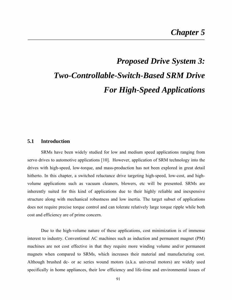
91
Chapter 5
Proposed Drive System 3:
Two-Controllable-Switch-Based SRM Drive
For High-Speed Applications
5.1 Introduction
SRMs have been widely studied for low and medium speed applications ranging from
servo drives to automotive applications [10]. However, application of SRM technology into the
drives with high-speed, low-torque, and mass-production has not been explored in great detail
hitherto. In this chapter, a switched reluctance drive targeting high-speed, low-cost, and high-
volume applications such as vacuum cleaners, blowers, etc will be presented. SRMs are
inherently suited for this kind of applications due to their highly reliable and inexpensive
structure along with mechanical robustness and low inertia. The target subset of applications
does not require precise torque control and can tolerate relatively large torque ripple while both
cost and efficiency are of prime concern.
Due to the high-volume nature of these applications, cost minimization is of immense
interest to industry. Conventional AC machines such as induction and permanent magnet (PM)
machines are not cost effective in that they require more winding volume and/or permanent
magnets when compared to SRMs, which increases their material and manufacturing cost.
Although brushed dc- or ac series wound motors (a.k.a. universal motors) are widely used
specifically in home appliances, their low efficiency and life-time and environmental issues of

92
the brush-commutator configuration become serious concerns. SRMs, however, are considered
by many to be rugged, inexpensive, fault-tolerant, and capable of high-speed operation, hence
opening up new opportunities for their selection into various applications.
This chapter presents the design and implementation of a high efficiency, low cost,
brushless, variable speed drive system with high speed capability. The drive system is realized
using a two-phase switched reluctance machine driven by a low cost split ac converter. The
machine has self-starting capability at any rotor position and is capable of running at a rated
speed up to 48,000r/min. The power converter has a low cost single-switch-per-phase (SSPP)
configuration.
Accurate mathematical modeling of the drive system including machine and power
electronic converter is described. Based on the derived model, the control system is designed and
its optimal control strategy in single-pulse operation mode is investigated. To find the optimal
switching angles in the single-pulse operation mode, three dimensional characteristics of the
machine efficiency as well as electromagnetic torque in terms of the advance and commutation
angles are developed from dynamic simulations. Optimization of the winding turns in the stator
is an important design aspect for SRMs and thus a study to find the optimal number of winding
turns considering motor efficiency and power converter ratings is also presented.
Dynamic simulation results are presented to validate the operation of the proposed drive
system. Experimental verification of the prototype drives system and its correlation with
analytical and simulation results are presented. First, static measurements of the winding
inductance and torque are carried out to correlate the obtained from the FEA simulation. In
addition, a full load test with a dynamometer setup has been performed to verify both steady-
state and dynamic performance of the proposed drive system.
The proposed drive system offers viable features such as low cost structure, high
efficiency, high reliability, and high speed capability and hence it can be a strong candidate for a
low cost brushless variable (high) speed application in low-cost, mass-production markets, where
both cost and efficiency are valued.

93
5.2 Proposed Drive System
5.2.1 Machine
Fig. 5.1 shows the prototype two-phase SRM of the proposed drive system. The motor is
a two-phase self-starting capable SRM with four stator poles and two rotor poles. It is designed
to run at rated speed of 38,000r/min and up to maximum speed of 48,000r/min. Although single-
phase SRMs are less expensive, recent research [10]-[13] shows that two-phase SRMs are
preferred from the viewpoint of performance, such as self-starting, better air-gap utilization,
lower torque ripple, and less acoustic noise. Figs. 5.2(a) and 5.2(b) show the phase inductance
and torque profiles, for designed two-phase SRM respectively, for one electrical cycle obtained
from finite element analysis (FEA). In order to produce starting torque at every rotor position, at
least one phase should be able to produce positive torque at any rotor position, i.e. the positive
inductance slope (dL/dθ > 0) region should overlap for both phases, as shown in Figs. 5.2 (a) and
5.2(b). This is achieved by increasing the rotor pole arc and creating a non-uniform air-gap via
rotor pole arc shaping.
Fig. 5.1 Prototype two-phase 4/2 SRM
A2
A1
B1 B2

94
(a) Inductance
(b) Torque
Fig. 5.2. Static inductance and torque profiles for each phase at 6A current to provide self-
starting capability at any position
5.2.2 Power Converter
The low cost split ac supply converter [35], [36] as shown in Fig. 5.3 has been chosen to
drive the machine. The converter employs a single-switch-per-phase topology that leads to a
reduced heat sink area and compact packaging due to low component count. Originally evolved
from the well-known split dc converter, the power converter employs a half-bridge rectifier
splitting the ac supply and the dc link mid-point is tied to the ac neutral. Therefore, the dc link
0.00000.00050.00100.00150.00200.00250.00300.00350.00400.0045
0 20 40 60 80 100 120 140 160 180
Phase A Phase B
Rotor position, deg
Indu
ctan
ce, H
0
0.01
0.02
0.03
0.04
0.05
0.06
0.07
0 20 40 60 80 100 120 140 160 180
Phase A Phase B
Torq
ue, N
m
Rotor position, deg
Torque overlap
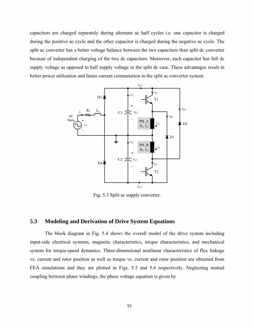
95
capacitors are charged separately during alternate ac half cycles i.e. one capacitor is charged
during the positive ac cycle and the other capacitor is charged during the negative ac cycle. The
split ac converter has a better voltage balance between the two capacitors than split dc converter
because of independent charging of the two dc capacitors. Moreover, each capacitor has full dc
supply voltage as opposed to half supply voltage in the split dc case. These advantages result in
better power utilization and faster current commutation in the split ac converter system.
Fig. 5.3 Split ac supply converter.
5.3 Modeling and Derivation of Drive System Equations
The block diagram in Fig. 5.4 shows the overall model of the drive system including
input-side electrical systems, magnetic characteristics, torque characteristics, and mechanical
system for torque-speed dynamics. Three-dimensional nonlinear characteristics of flux linkage
vs. current and rotor position as well as torque vs. current and rotor position are obtained from
FEA simulations and they are plotted in Figs. 5.5 and 5.6 respectively. Neglecting mutual
coupling between phase windings, the phase voltage equation is given by
idc2
D1
D2
vC1
+
-
C1
C2 vC2
T1
T2
D3
D4
iT1
iT2
iD1
iD2
ia
ib
iC1
iC2
idc1
is
+
-
+
-
vs
AC Main
Rs Ls
PH_ARa, La
PH_BRb, Lb
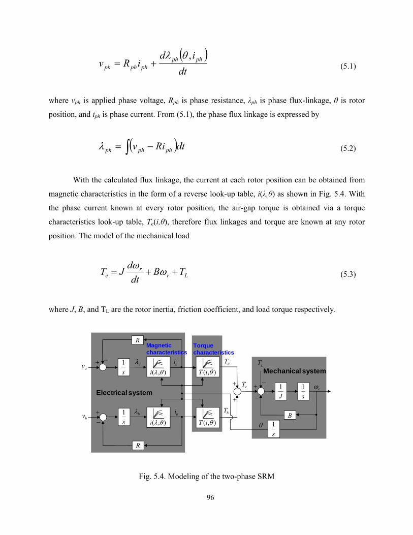
96
( )dt
idiRv phph
phphph
,θλ+= (5.1)
where vph is applied phase voltage, Rph is phase resistance, λph is phase flux-linkage, θ is rotor
position, and iph is phase current. From (5.1), the phase flux linkage is expressed by
( )∫ −= dtRiv phphphλ (5.2)
With the calculated flux linkage, the current at each rotor position can be obtained from
magnetic characteristics in the form of a reverse look-up table, i(λ,θ) as shown in Fig. 5.4. With
the phase current known at every rotor position, the air-gap torque is obtained via a torque
characteristics look-up table, Te(i,θ), therefore flux linkages and torque are known at any rotor
position. The model of the mechanical load
Lrr
e TBdt
dJT ++= ωω (5.3)
where J, B, and TL are the rotor inertia, friction coefficient, and load torque respectively.
Fig. 5.4. Modeling of the two-phase SRM
Electrical system
bvs1 bi+
−
aT
bT
avs1 ai+ −
aλ LT
s1+
−rω
J1
B
−
bλ
eT
θ
+
+
Mechanical system
R
R
s1
Magnetic characteristics
Torque characteristics
),( θiT
),( θiT),( θλi
),( θλi
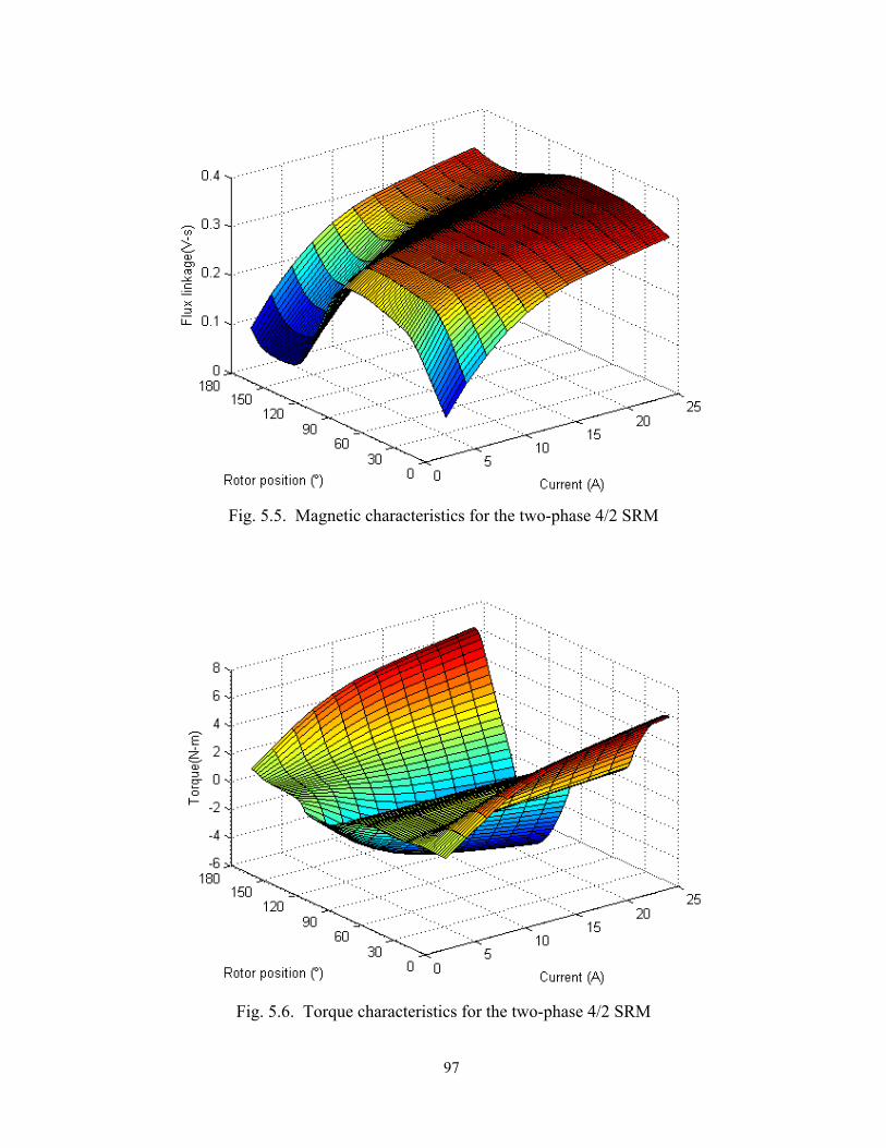
97
Fig. 5.5. Magnetic characteristics for the two-phase 4/2 SRM
Fig. 5.6. Torque characteristics for the two-phase 4/2 SRM
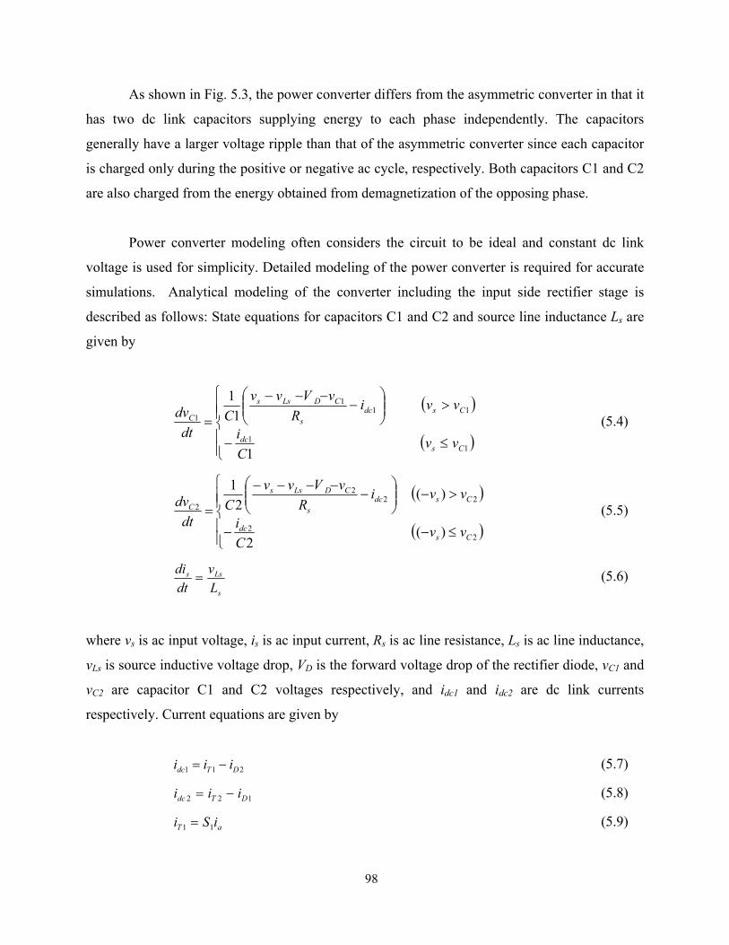
98
As shown in Fig. 5.3, the power converter differs from the asymmetric converter in that it
has two dc link capacitors supplying energy to each phase independently. The capacitors
generally have a larger voltage ripple than that of the asymmetric converter since each capacitor
is charged only during the positive or negative ac cycle, respectively. Both capacitors C1 and C2
are also charged from the energy obtained from demagnetization of the opposing phase.
Power converter modeling often considers the circuit to be ideal and constant dc link
voltage is used for simplicity. Detailed modeling of the power converter is required for accurate
simulations. Analytical modeling of the converter including the input side rectifier stage is
described as follows: State equations for capacitors C1 and C2 and source line inductance Ls are
given by
( )
( )⎪⎪⎩
⎪⎪⎨
⎧
≤−
>⎟⎟⎠
⎞⎜⎜⎝
⎛−
−−−
=
11
111
1
1
11
Csdc
Csdcs
CDLss
C
vvCi
vviR
vVvvC
dtdv (5.4)
( )
( )⎪⎪⎩
⎪⎪⎨
⎧
≤−−
>−⎟⎟⎠
⎞⎜⎜⎝
⎛−
−−−−
=
22
222
2
)(2
)(2
1
Csdc
Csdcs
CDLss
C
vvCi
vviR
vVvvC
dtdv (5.5)
s
Lss
Lv
dtdi
= (5.6)
where vs is ac input voltage, is is ac input current, Rs is ac line resistance, Ls is ac line inductance,
vLs is source inductive voltage drop, VD is the forward voltage drop of the rectifier diode, vC1 and
vC2 are capacitor C1 and C2 voltages respectively, and idc1 and idc2 are dc link currents
respectively. Current equations are given by
211 DTdc iii −= (5.7)
122 DTdc iii −= (5.8)
aT iSi 11 = (5.9)

99
bT iSi 22 = (5.10)
( ) aD iSi 11 1−= (5.11)
( ) bD iSi 12 1 −= (5.12)
where iT1 and iT2 are transistor T1 and T2 currents, iD1 and iD2 are diode D1 and D2 currents, ia
and ib are phase currents, and S1and S2 are switching functions of transistors T1 and T2. Turning
on T1 and T2 results in vC1 and vC2 being applied to phase A and B windings, respectively, for
magnetization. Turning off T1 and T2 causes -vC2 and -vC1 to be applied to phase A and B
windings, respectively, for demagnetization. Therefore, the terminal voltage applied to each
phase is given by
( ) ( )( )DCTCa VvSVvSv −−−−= 2111 1 (5.13)
( ) ( )( )DCTCb VvSVvSv −−−−= 1222 1 (5.14)
2or1,10 == xSx (5.15)
where VT is transistor saturation voltage, VD is the diode forward drop, and Sx is the switching
function for transistor T1 or T2.
5.4 Converter Modes of Operation
Although the converter circuit looks simple, thorough understanding of the converter
operation may be complicated. Unlike the conventional asymmetric converter with only a single
dc link, the split ac converter has two capacitors forming two separate dc link for each phase.
The mid-point of these capacitors is tied with the negative ac rail and thus each capacitor is
charged during only half ac cycle respectively. In addition, each phase experiences different
capacitors for magnetization and demagnetization respectively. All of these add to complexity of
the converter operation. Examining all the possible switching states of T1 and T2 as well as the
charging and discharging status of C1 and C2 with respect to ac cycle, six different modes of
operation can be derived for each phase and they are depicted in Fig. 5.7 and 5.8. Proper
understanding of the converter operation is important for capacitor sizing as well as the reliable
starting scheme.

100
Phase A magnetization (T1 on) Phase A demagnetization (T1 off) Po
sitiv
e ac
mai
n ch
argi
ng C
1
Mode A1 (vin > vC1, T1 on)
Mode A2 (vin > vC1, T1 off)
Neg
ativ
e ac
mai
n ch
argi
ng C
2
Mode A3 (-vin > vC1, T1 on)
Mode A4 (-vin > vC1, T1 off)
Ac
mai
n no
t cha
ring
C1
or C
2
Mode A5 (|-vin| < vC1 or |-vin| < vC2, T1 on)
Mode A6 (|-vin| < vC1 or |-vin| < vC2, T1 off)
Fig. 5.7 Converter modes of operation for phase A excitation
D1
Vdc +
-C1
C2
Vdc
T1
T2
Phase A
Phase B
D3
D4
D2
+
-

101
Phase B magnetization (T2 on) Phase B demagnetization (T2 off) Po
sitiv
e ac
mai
n ch
argi
ng C
1
Mode B1 (vin > vC1, T2 on)
Mode B2 (vin > vC1, T2 off)
Neg
ativ
e ac
mai
n ch
argi
ng C
2
Mode B3 (-vin > vC1, T2 on)
Mode B4 (-vin > vC1, T2 off)
Ac
mai
n no
t cha
ring
C1
or C
2
Mode B5 (|-vin| < vC1 or |-vin| < vC2, T2 on)
Mode B6 (|-vin| < vC1 or |-vin| < vC2, T2 off)
Fig. 5.8 Converter modes of operation for phase B excitation
D2
D1
Vdc +
-C1
C2
Vdc
T1
T2
Phase A
Phase B
D3
D4 +
-

102
5.5 Optimal Efficiency Control of SRM Drives in Single-Pulse Operation
5.5.1 Switching Angle Control
The control scheme presented here is to achieve optimal efficiency for a given operating
condition. The key to achieving optimal efficiency is to maximize the energy conversion per
phase excitation, i.e. the ratio of average torque to rms phase current. At given speed, mechanical
output is proportional to the average output torque, and the electrical input is proportional to the
rms phase current. The motor drive of interest is intended to run at high speeds where current
control is infeasible; therefore, the drive system will be running in single-pulse mode. In single-
pulse mode, the switching angles (turn-on, turn-off) defined in Fig. 5.9 are the only control
parameters and thus, the proper firing of the excitation will play a key role for the optimal
efficiency control.
θu Aligned rotor position with minimum inductance. θa Unaligned rotor position with maximum inductance. θon Rotor position at which the switch is turned on. θoff Rotor position at which the switch is turned off. θdwell Position interval between turn-on and turn-off angle. θadv Position interval between unaligned and turn-on angle. θcom Position interval between aligned and turn-off angle.
Fig. 5.9. Switching angles and typical phase current waveform in single–pulse operation mode
θoffθon θaθu
θadvθcom
iph
Lmin
Lmax
θdwell
θon = θu– θadv
θoff = θa– θcom = θon+ θdwell

103
As shown in Fig. 5.7, beyond unaligned position, θu, when the back-EMF exceeds the
supply voltage the phase current is forced to decrease during conduction. Therefore, in order to
produce the desired torque, it is necessary to advance the turn-on of phase excitation
substantially and to adjust the turn-off angle before the significant braking torque is produced.
5.5.2 Conventional Switching Angle Control
A conventional method to find an optimal turn-on angle is based on the phase voltage
equation [37]. Neglecting mutual coupling between the phases, the phase voltage equation of the
SRM is given by
phph ph ph
di dLv Ri L idt d
ωθ
= + + (5.16)
The optimal turn-on angle is defined such that advancing the turn-on makes the current builds up
fast at unaligned region and reaches its reference value at the start of pole overlap, and it can be
calculated using (5.16). The back-EMF is zero at unaligned position and at low speed IR drop of
the stator resistor is negligible compared to source voltage. Thus, the voltage equation reduces to
phph
di Iv L Ldt
ωθΔ
= =Δ (5.17)
In order for the phase current to reach its reference value, Iref at θu, the required advanced angle
can be calculated by
min refadv
dc
L IV
ωθ =
(5.18)
where Lmin is the inductance at unaligned position and Vdc is dc supply voltage. Therefore, the turn-on angle is

104
min refon u
dc
L IV
ωθ θ= −
(5.19)
Above estimation, however, is not accurate at higher speed since the available source
voltage is not sufficient to generate the commanded current due to the back-EMF comparable to
the source voltage. Therefore, further advancing of turn-on angle is needed. To ensure that the
correct advance angle is achieved under higher speed region, several methods in a form of
closed-loop angle controller have been developed [37]-[42]. Fig. 5.8 shows one of the simple
algorithms for angle compensation methods. With insufficient advancing of excitation, the
current cannot reach Iref at θu, and it continues to increase beyond θu. Then, the angle detector
captures the rotor position, θp at instant when the measured phase current first matches Iref. Then,
the feedback controller fine-tunes θp to match θu is added to initial estimation of advance angle.
However, in high-speed single-pulse operation mode, the above method may not be very
accurate since the current cannot be maintained at the reference value beyond θu.
Fig. 5.10. Closed-loop angle controller
min refadv
dc
L IV
ωθ =

105
The turn-off angle is more difficult to determine directly than turn-on angle and it is often
obtained from trial-and-error experimental data or a piece-wise linear model neglecting magnetic
saturation. From the experimental or simulation data, the turn-off angle can be represented
analytically [41], [42]
1 2 3 4off ref refk k I k I kθ ω ω= + + + (5.20)
where k1, k2, k3, and k4 are curve fit parameters.
5.5.3 Proposed Angle Control Scheme Based on Characterization of Optimal
Switching Angles in Single-Pulse Operation As described in the previous sections, the optimal torque production for maximum
efficiency can be achieved by properly selecting both turn-on and turn-off angles. Figs. 5.11 and
5.12 show various phase current waveforms for different switching angles at the same speed. The
effect of variation of turn-on angle with a constant turn-off is shown in Fig. 5.11, and the effect
of variation of turn-off angle with a constant turn-on is shown in Fig. 5.12, respectively. As
shown in Fig. 5.11, the more turn-on angle is advanced, the faster and higher rise of the phase
current is possible due to small inductance and negligible back-EMF, hence facilitating torque
production. As can be seen from Fig. 5.12, if the turn-off angle is delayed, i.e. increased dwell
angle, more torque is produced but not as much as advancing the turn-on angle due to the
substantial back-EMF and inductance at this interval. Therefore, it can be inferred that turn-on
angle has more impact on torque production than turn-off angle.

106
Fig. 5.11. Effect of turn-on angle on phase excitation current
Fig. 5.12. Effect of turn-off angle on phase excitation current
Fig. 5.13 shows several possible choices of switching angles to produce the same average
torque. Although they produce the same torque, their rms currents are different. Therefore, an
angle combination (turn-on and turn-off) resulting in minimum rms current is the optimal
operating condition for maximum efficiency. As can be seen from current waveform, (1) in Fig.
5.13, a substantial advance of turn-on angle allows higher peak current at θu facilitating torque
4°8°12°16°20°24°
0°
35°40°45°50°55°60°
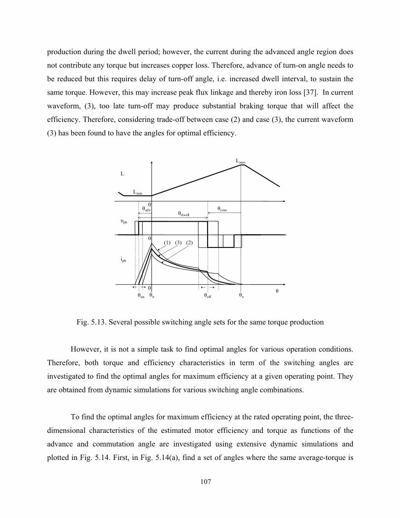
107
production during the dwell period; however, the current during the advanced angle region does
not contribute any torque but increases copper loss. Therefore, advance of turn-on angle needs to
be reduced but this requires delay of turn-off angle, i.e. increased dwell interval, to sustain the
same torque. However, this may increase peak flux linkage and thereby iron loss [37]. In current
waveform, (3), too late turn-off may produce substantial braking torque that will affect the
efficiency. Therefore, considering trade-off between case (2) and case (3), the current waveform
(3) has been found to have the angles for optimal efficiency.
Fig. 5.13. Several possible switching angle sets for the same torque production
However, it is not a simple task to find optimal angles for various operation conditions.
Therefore, both torque and efficiency characteristics in term of the switching angles are
investigated to find the optimal angles for maximum efficiency at a given operating point. They
are obtained from dynamic simulations for various switching angle combinations.
To find the optimal angles for maximum efficiency at the rated operating point, the three-
dimensional characteristics of the estimated motor efficiency and torque as functions of the
advance and commutation angle are investigated using extensive dynamic simulations and
plotted in Fig. 5.14. First, in Fig. 5.14(a), find a set of angles where the same average-torque is
θu θaθon θoff
θadv0
θcom
(1) (3) (2)
L
υph
iph
Lmin
Lmax
θdwell
θ
0
0

108
produced. Then, from these angles, the angle that gives the maximum efficiency in Fig. 5.14(b)
is identified.
(a)
(b)
Fig. 5.14. Three-dimensional characteristics of (a) electromagnetic torque and (b) efficiency
with respect advance and commutation angles
05
1015
20
20
30
40
500
0.1
0.2
0.3
0.4
0.5To
rque
( N-m
)1
23
45 6
05
1015
20
20
30
40
5065
70
75
80
85
Effi
cien
cy (%
)
12
34
5 6

109
In Figs. 5.14(a) and 5.14(b), the three-dimensional characteristics of the estimated motor
efficiency and torque as functions of the advance and commutation angle are plotted. Spline
interpolation was utilized for curve-fitting to discrete data points. From Fig. 5.14(a), first find a
set of angles where the same average-torque is produced. Then, from these angles, the angle that
gives the maximum efficiency in Fig. 5.14(b) is identified. This optimum angle produces the
required torque with maximum efficiency. For example, the 3D plot in Fig. 5.14(a) indicates 6
sets of switching angles, 1, 2, 3…6, which produce the same average torque. From Fig. 5.14(b),
it is observed that angle set #2 (θadv = 16°, θcom = 42°) has the highest efficiency and that
efficiency is more sensitive to advance angle than commutation angle. These angle-torque and
angle-efficiency characteristics can be used to design a simple low cost controller that is tuned
off-line.
5.6 Drive System Controller
The closed-loop speed controlled drive system is illustrated in Fig. 5.15. Two common
modes of operation are used in SRM drives, namely, PWM current control and single pulse
control. PWM control is used when the motor speed is below the base speed and single-pulse
control is used beyond the base speed as the back-EMF is comparable to the dc supply voltage in
this regime. In general, maximum efficiency is achieved in the single-pulse mode around the
rated operating point. The targeted operating speed of the proposed SRM is high with maximized
efficiency where only average torque is controlled; hence the motor will be operating with single
pulse control most of the time. However, both PWM current controller and single-pulse
controller have been developed to extend the drive’s operational capability.
In Fig. 5.15, the outer loop is a PI speed control and the inner control loop has two
alternative controllers implemented, namely, a PWM current controller for low and medium
speed regime and a single-pulse controller for high speed regime. The drive controller operates
as follows. If the commanded speed is below the base speed, the machine runs under current-
control mode as illustrated in the upper part of the inner control loop in Fig. 5.15. The reference
torque is achieved by increasing the current amplitude and shifting the switching angles as a
function of speed and current command using estimation for advance angle in (5.18). For high
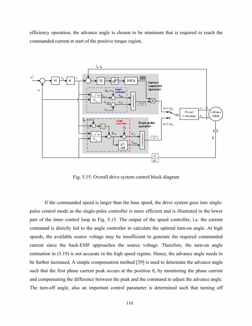
110
efficiency operation, the advance angle is chosen to be minimum that is required to reach the
commanded current at start of the positive torque region.
Fig. 5.15. Overall drive system control block diagram
If the commanded speed is larger than the base speed, the drive system goes into single-
pulse control mode as the single-pulse controller is more efficient and is illustrated in the lower
part of the inner control loop in Fig. 5.15. The output of the speed controller, i.e. the current
command is directly fed to the angle controller to calculate the optimal turn-on angle. At high
speeds, the available source voltage may be insufficient to generate the required commanded
current since the back-EMF approaches the source voltage. Therefore, the turn-on angle
estimation in (5.19) is not accurate in the high speed regime. Hence, the advance angle needs to
be further increased. A simple compensation method [39] is used to determine the advance angle
such that the first phase current peak occurs at the position θu by monitoring the phase current
and compensating the difference between the peak and the command to adjust the advance angle.
The turn-off angle, also an important control parameter is determined such that turning off
dc
*u
VωiL
dc
*u
VωiL
com
mut
ator
Bωω ≥
Bωω <
com
mut
ator
dtd

111
sooner allows the current decay fast before preventing the production of excessive braking
torque. The turn-off angle for the drive controller is determined by the characterization described
in the previous section.
5.7 Selection of Optimal Number of Winding Turns
One of the important SRM design factors which affect motor efficiency is the number of
turns in the phase winding and thus the optimal number of turns is determined so that the
maximum efficiency is achieved for given rated torque and speed. Fig. 5.16 shows a cross-
sectional view of a stator pole and winding mounted around it.
Fig. 5.16. Cross-sectional view of a winding mounted on a stator pole
Assuming that a rectangular cross-sectional area around a stator pole in Fig. 5.16 is the
maximum effective winding area, the conductor sizes were chosen such that each combination of
size and number provides approximately the same conductor area. The cross-sectional winding
area AW assumes a rectangular winding slot area and is expressed as
WCW fANA ⋅⋅≈ (5.21)
Effective cross-sectional winding area (Aw)
Effective cross-sectional conductor area (Ac)
Number of turns per pole: NNumber of turns per phase: N×2
112
where N, AC, and fw are the number of turns, wire cross-sectional area, and fill factor (0.5 < fw <
0.8) respectively. The phase winding resistance is calculated by scaling one turn’s resistance by
the number of turns.
NAlR
C
mph ⋅⋅⎟⎟
⎠
⎞⎜⎜⎝
⎛= 2ρ (5.22)
lm is a mean-length of one turn. Once the resistance of the initial winding, R1, is determined, the
resistance of different winding numbers, R2 is calculated using
2
1
1
212
C
C
AA
NNRR ⋅⋅≈ (5.23)
The resistances for a range of winding turns were calculated and a single-pulse mode
simulation was performed at the rated operating point for each turns count. Table 5.1 shows the
predicted performance at the rated operating point obtained from dynamic simulations for
different number of turns per stator pole including the phase resistance Rph, phase rms current Irms,
converter power loss Pconv and winding copper loss Pcu. A larger number of turns increases the
phase resistance and inductance, and retards the current build-up at turn-on in single pulse mode.
As shown in Fig. 5.17, an increase in the advance angle is necessary to increase phase current to
compensate for the higher inductance and resistance. Since the excitation occurs where dL/dθ≈0,
it does not contribute any torque but increases copper loss. Therefore increasing the number of
turns at the upper range of turn count is detrimental to the efficiency.

113
Table 5.1
Predicted losses for different number of turns
Number of turns Rph [Ω] Irms [A] Pconv [W] Pcu [W] Total loss [w]
30 0.248 13.02 28.41 74.9 103.31
35 0.295 12.23 27.36 80.3 107.66
40 0.338 11.37 26.22 87.4 113.62
45 0.426 10.49 25.58 93.8 119.38
50 0.532 9.70 24.16 100.1 124.26
55 0.661 9.33 23.23 115.1 138.33
Fig. 5.17. Phase currents for different number of turns running at the same operating point
(38,000 r/min, 0.3N-m)
Cur
rent
[A]
time[s]
Cur
rent
[A]
θadv 30 turns per pole
35 turns per poleθadv
θadv
Cur
rent
[A] 40 turns per pole

114
On the other hand, a small number of turns allows phase current to build up quickly after
turn-on and reduces the advance angle, thereby increasing efficiency. However, the rms current
level to torque ratio is high resulting in a higher drive current rating and cost. As shown in Fig.
5.17, a lower number of turns correspond to a lower power loss and higher efficiency but higher
rms current. From Table 5.1, 35 turns has been chosen for the prototype SRM drive considering
the power converter VA rating and ac source constraints.
5.8 Simulation Verification
Based on the model derived in the previous sections, dynamic simulations are performed.
The nonlinear machine characteristics are modeled from FEA results and non-ideal converter
circuit model as well as control algorithms are implemented using Matlab. The simulation results
are shown in Figs. 5.18, 5.19, and 5.20. Fig. 5.18 shows the waveforms of dc link capacitors, C1
and C2 that are charged during positive ac cycle (C1) and negative ac cycle (C2) respectively
with approximately 20% voltage ripple. Note that each phase current is multiplied by five times
of the original waveforms for clearer comparison. As observed from Fig. 5.18, the fluctuation in
current waveform is due to the ripple of the dc link voltages that are applied to each phase, hence
resulting in ripples in flux linkage and torque. Figs. 5.19 and 5.20 show the capability of the
designed drive system capable of running at rated speed of 38,000r/min with full load power
(1.2kW) and running at 48,000r/min with approximately 83% of full load power. Base on
performance prediction through the dynamic simulation, the experimental results and its
correlation with the simulation results will be discussed in the next section.

115
Fig. 5.18. AC input and dc link capacitor voltages along with the phase currents
Fig. 5.19. Steady- state waveforms running at 38000r/min, 0.3N-m (1.2kW)
time[s]
vs 5×ia
-vs 5×ib
vC1
vC2
Volta
ge [V
]C
urre
nt [A
]Vo
ltage
[V]
Cur
rent
[A]
0
0.05
0
20
40
−200
0
200
0.035 0.0355 0.036 0.0365 0.0370
0.5
1
time [s]
Flux
link
age
[V-s
ec]
Phas
e cur
rent
s[A
]Ph
ase v
olta
ges
[V]
Torq
ue[N
-m]
λa λb
ia ib
TeTavg= 0.3N-m
va vb

116
Fig. 5.20. Steady-state waveforms running at 48000 r/min, 0.20N-m (1kW)
5.9 Experimental Results
5.9.1 Construction of Prototype Drive System
Fig. 5.21 shows a prototype two-phase 4/2 SRM with phase windings mounted on the
stator poles and a rotor mounted on an end bell. The specification of the prototype motor is listed
in Table 5.2. Due high stroke (commutation) frequency at high speeds, the thickness of the iron
steel lamination for both stator and rotor should be as thin as possible to minimize eddy current
loss. In the prototype motor, a lamination with 26 gauge thickness was used.
0
0.05
0
20
40
−200
0
200
0.035 0.0355 0.036 0.0365 0.0370
0.5
1
time [s]
Flux
link
age
[V-s
ec]
Phas
e cur
rent
s[A
]Ph
ase v
olta
ges
[V]
Torq
ue[N
-m]
λa λb
ia ib
va vb
Te
Tavg= 0.2N-m

117
Fig. 5.21. Prototype two-phase 4/2 SRM
Table 5.2 Specification of the prototype two-phase 4/2 SRM
ITEM VALUE
Rated output power 1.2kW
Rated/Max. speed 38,000/48,000rpm
Input ac line voltage 120Vrms
Stator outer dimension 76.4mm × 76.4mm
Number of pole(stator/rotor) 4/2
Lamination stack 25.4mm
Aligned phase inductance 4.3mH at 2A
Unaligned phase inductance 0.3mH at 2A
Fig. 5.22 shows the drive converter electronics. The on-board power supply and gate
drive will sit vertically on the 3”x3” main converter board, making the overall converter
electronics very compact. In the split ac supply converter, the dc link capacitors should be
selected while considering the trade-off between capacitance, cost, and voltage ripple. The most
severe voltage ripple occurs when the phase winding is fed by the discharging capacitor. As a
US quarter

118
worst case, assuming 700W per phase output power with 20% voltage ripple, the minimum
capacitance can be estimated using the following equations. Vmax and Vmin are the maximum and
minimum capacitor voltage, and ∆t is the maximum discharging time.
)(21 2
min2
max VVCW −=Δ (4.24)
uFVV
tPC 200022
min2
max
≈−Δ⋅⋅
= (4.25)
Fig. 5.22. Prototype power converter and drive electronics
5.9.2 Static Tests To verify the prototyping quality and static performance of the motor, the inductance and
torque profiles were measured and compared with the FEA simulation results using the setup
shown in Fig. 5.23. Figs. 5.24 and 5.25 show the measured inductance and torque of the
prototype machine and its correlation with FEA data. The static inductance and torque is
measured every four degree at 6A and 8A excitation for a complete commutation cycle of 180
degree. The maximum error between FEA and measured inductance profiles is 7.2%, which may
arise from the inaccurate B-H characteristics used in FEA simulations and manufacturing quality
of the prototype. The maximum error between static FEA and measured torque profiles is 9.2%.
Power converter
SMPS
Gate drive
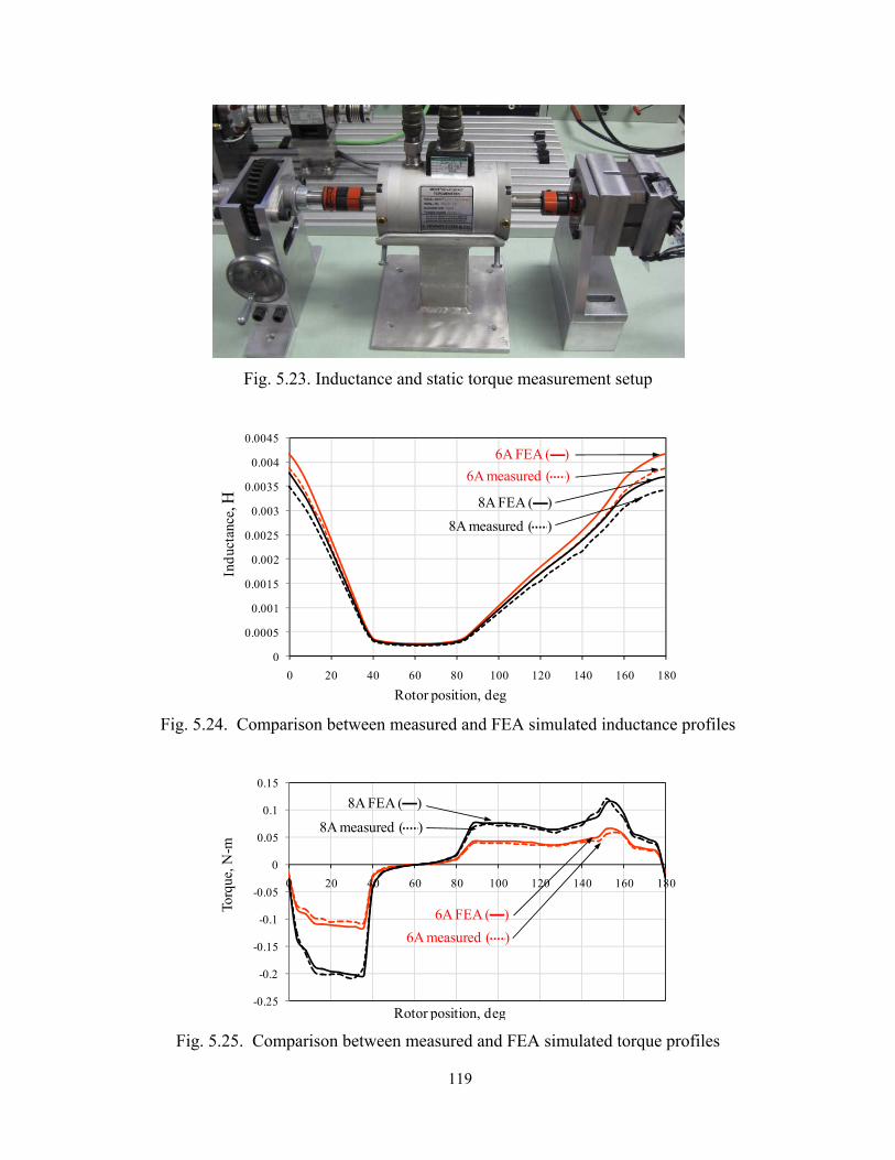
119
Fig. 5.23. Inductance and static torque measurement setup
Fig. 5.24. Comparison between measured and FEA simulated inductance profiles
Fig. 5.25. Comparison between measured and FEA simulated torque profiles
0
0.0005
0.001
0.0015
0.002
0.0025
0.003
0.0035
0.004
0.0045
0 20 40 60 80 100 120 140 160 180
Indu
ctan
ce, H
Rotor position, deg
6A FEA ( )
8A FEA ( )
6A measured ( )
8A measured ( )
-0.25
-0.2
-0.15
-0.1
-0.05
0
0.05
0.1
0.15
0 20 40 60 80 100 120 140 160 180
Rotor position, deg
Torq
ue, N
-m
6A FEA ( )
8A FEA ( )
6A measured ( )
8A measured ( )
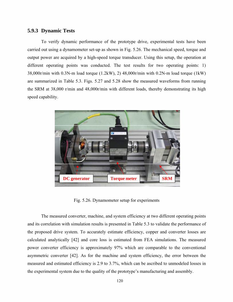
120
5.9.3 Dynamic Tests
To verify dynamic performance of the prototype drive, experimental tests have been
carried out using a dynamometer set-up as shown in Fig. 5.26. The mechanical speed, torque and
output power are acquired by a high-speed torque transducer. Using this setup, the operation at
different operating points was conducted. The test results for two operating points: 1)
38,000r/min with 0.3N-m load torque (1.2kW), 2) 48,000r/min with 0.2N-m load torque (1kW)
are summarized in Table 5.3. Figs. 5.27 and 5.28 show the measured waveforms from running
the SRM at 38,000 r/min and 48,000r/min with different loads, thereby demonstrating its high
speed capability.
Fig. 5.26. Dynamometer setup for experiments
The measured converter, machine, and system efficiency at two different operating points
and its correlation with simulation results is presented in Table 5.3 to validate the performance of
the proposed drive system. To accurately estimate efficiency, copper and converter losses are
calculated analytically [42] and core loss is estimated from FEA simulations. The measured
power converter efficiency is approximately 97% which are comparable to the conventional
asymmetric converter [42]. As for the machine and system efficiency, the error between the
measured and estimated efficiency is 2.9 to 3.7%, which can be ascribed to unmodeled losses in
the experimental system due to the quality of the prototype’s manufacturing and assembly.
SRMTorque meterDC generator

121
Fig. 5.27. Measured waveforms of phase current phase voltage, and phase input power operating
for 38000 r/min, 0.3N-m (1.2kW)
Fig. 5.28. Measured waveforms of phase current phase voltage, and phase input power operating
for 48000 r/min, 0.2N-m (1kW)
vph
(200V/div)
Pph
(4kW/div)
t (0.2ms/div)
iph
(20A/div)
vph
(200V/div)
Pph
(5kW/div)
iph
(20A/div)
t (0.2ms/div)

122
Table 5.3 Specification of the prototype two-phase 4/2 SRM
Output [kW]
Converter [%] Machine [%] System [%]
Estimated Measured Estimated Measured Estimated Measured
1.0 98.1 96.9 75.6 72.7 74.2 70.5
1.2 98.5 97.6 76.1 73.8 75.0 72.1
5.10 Summary
A low cost, high efficiency, high speed SRM drive system is presented in this paper. The
drive system is realized with a two-phase SRM and a split ac converter. The drive system is
designed for running at 38,000r/min (1.2kW) and maximum speed of 48,000r/min. The
contributions of this paper are:
1) Modeling, design and analysis of a low cost high speed SRM drive system is
presented and its performance has been validated via simulations and experiments.
2) The high speed capability of the proposed drive system was demonstrated
experimentally.
3) Optimization of the turn on and turn off angles was performed to maximize system
efficiency at the rated operating point. Switching angle vs. efficiency and torque in
the single-pulse mode has been characterized to achieve the optimal operating
efficiency.
4) Number of winding turns in the SRM was optimized by FEA and dynamic
simulations in terms of efficiency and converter rating.
5) The presented drive system can be a strong candidate for high-speed low-cost
applications where both cost and performance are valued.

123
Chapter 6
Position Sensorless Operation of
SRM Drives
6.1 Introduction
The switched reluctance motor (SRM) produces torque through excitation of phase
winding in synchronism with the rotor position. Therefore, the SRM requires rotor position
information for proper control, which is achieved pervasively by position sensors mechanically
mounted on the rotor shaft. These sensors, however, require mounting labor and space, and
hence add to cost and packaging size of the drive system, which is not desired by manufacturers.
In addition, some applications are reluctant to accept the sensor because of reliability,
environmental constraints, etc. Therefore, extensive research has been carried out for decades to
find methods for rotor position and/or speed estimation without resorting to those sensors.
Various methods for position sensorless estimation and control have been proposed hitherto;
however, it is difficult to find one particular method suitable for all types of applications since
their selection primarily depends on specific application and operating speed.
A new, simple method for position sensorless control for SRMs is proposed and
described in this chapter. Basic concept underlying this scheme is use of linearized relationship
between the rotor position, inductance, and the rate of change of current. Two consecutive
switch-on times of the controllable switch in hysteresis current control are compared to estimate

124
the rotor position and speed. Using this method, the unaligned and aligned positions which can
be used as default turn-on and turn-off angles is determined.
The proposed method is very simple to implement in that it does not require complex
computation or lookup table and thereby suitable for low cost applications. The method is robust
in it is not dependent on the motor parameter variation.
6.2 State-of-the-art-review
Most position sensorless techniques utilize the fundamental principle the SRM’s
magnetic characteristic, i.e. the unique relationship between the flux linkage (or inductance),
rotor position, and excitation current. Therefore, a key to the successful realization of a
sensorless SRM drive is a reliable flux linkage or inductance estimate during operation.
The flux-current methods in [44], [45] estimate flux linkage by open-loop integration
with measured terminal signals (voltage and current) and then extracts rotor position from the
stored three-dimensional data between flux, current, and rotor position. While this approach is
simple and more suitable for high speed, single-pulse operation, it needs a large amount of
lookup tables and can have significant estimation errors at low speed, chopping mode operation
where the effect of the winding resistance becomes significant. Flux or inductance variation can
be obtained directly using sensing coils [46], [47], but the extra coils may cause coupling with
main power signals and add to the manufacturing cost and effort. However, the extra coils may
cause coupling with main power signals and add to the manufacturing cost and effort.
Observer-based methods [48]-[50] utilize model-based estimators to estimate state
variables such as flux, speed, or rotor position by real-time computation with measured phase
voltage and currents. Although these methods are valid over wide speed range, substantial real-
time computation and high sensitivity to parameter variation are their major drawbacks.
Intelligent control methods such as neural networks and fuzzy logics in [51]-[53]
provides an inherent capability to identification which is capable of adaptation of parameter
change in contrast to static memory. However, such an approach requires off-line training and

125
depends on the designers’ experience. An approach to decrease the computation effort
significantly is proposed in [54].
Inductance based methods [55]-[59] exploit the relationship between the phase self-
inductance (or incremental inductance) and rotor position for each excitation current. Phase
inductance is obtained from analytical model using terminal measurement of phase currents and
then the relationship between the rotor position and the self-inductance is derived using finite
element analysis (FEA) results or off-line measurement. The phase inductance variation can be
alternatively estimated by injecting a high frequency diagnostic signal into the inactive phase
[22]-[23] but inter-phase coupling, switching noise interference, eddy current losses are the
major drawbacks of this method.
Sensorless control proposed in [60]-[61] employed the fact that under certain
assumptions the current rise and fall times within the switching cycle are proportional to the
incremental inductance from which the rotor position can be extracted.. The incremental
inductance is calculated using the voltage equation with measured current increment and rise or
fall time and then obtain rotor position from the stored the incremental inductance data. The
major drawback of this method is that the imprecise computation of back-EMF and uncertain
winding resistance deteriorates the estimation accuracy. In addition, the incremental inductance
is bi-valued even within half a rotor pole pitch at current equal to or greater than 50% of the
rated current [56].
6.3 Proposed Sensorless Control Algorithm
The fundamental idea of the proposed sensorless control is that the rate of change of
current depends on the phase self-inductance, which in turn depends on the rotor position. In this
regard, it is similar to incremental inductance based method [59],[60]. However, the proposed
method does not require magnetization data on-line calculation of the inductance and mapping of
inductance–position relationship and hence no off-line measurement or lookup table is necessary.
Instead, by comparing two consecutive switching times in the hysteresis current control mode,
the proper commutation of the motor as well as the speed estimation can be achieved. The
advantages of the proposed methods are summarized as follows.

126
No a priori knowledge of inductance profile is required
No pre-stored data of magnetic curve or inductance is needed.
It is simple to implement.
It is applicable to any conventional SRM.
No extra hardware is required.
Insensitive to system parameter variations
6.3.1 Principle of Estimation
The basic principle of the proposed sensorless control is illustrated in Fig. 6.1. In an
unsaturated magnetization case, the voltage equation for the main phase winding can be
approximated from (6.1) as
dtdL
idtdi
LiRv aa
aaaaa
)()(
θθ ++= (6.1)
where La is the angle dependent main phase self inductance.
Assuming the motor is running at a constant speed, voltage equations at two sampling
times for any two consecutive switch-on periods can be expressed respectively by
dttdL
tidt
tditLtiRtv a
aa
aaaa)(
)()(
)()()( 11
1111 ++= (6.2)
dttdL
tidt
tditLtiRtv a
aa
aaaa)(
)()(
)()()( 22
2222 ++= (6.3)

127
Fig. 6.1. Relationship between inductance and rate of change of current.
The voltage applied to main winding for each case is the dc bus voltage, i.e. va(t1) = va(t2)
=Vdc. Assuming good current regulation (hysteresis control employed herein), each instantaneous
current at t1 and t2 is comparable to the reference value, i.e. ia(t1) ≈ ia(t2) ≈ i , which yields
)()( 21 tiRtiR aaaa ≈ (6.4)
Assuming a non-saturated linear inductance case, the slope of the main phase inductance
profile, dLa(θ)/dt is constant in the motoring region. Therefore, the third terms of both (6.2) and
(6.3) can be assumed to be the same:
dttdi )( 2
dttdi )( 1
dttdi n )(
dttdi n )( 1−
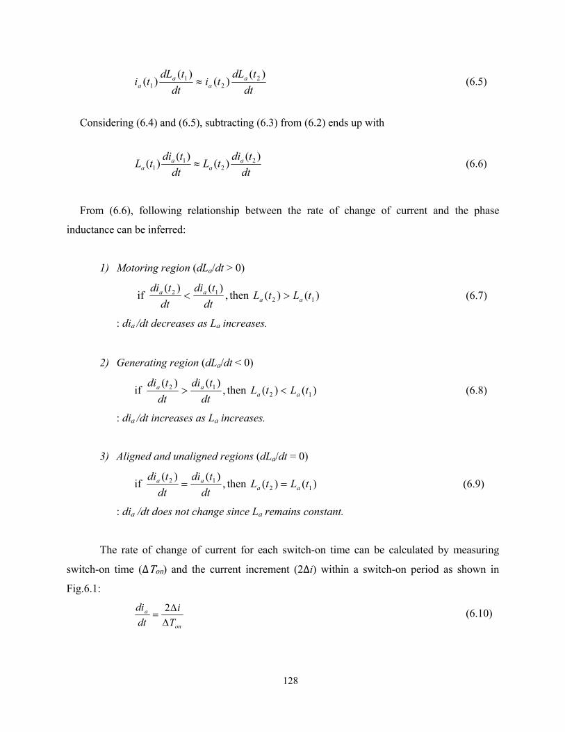
128
dttdL
tidt
tdLti a
aa
a)(
)()(
)( 22
11 ≈ (6.5)
Considering (6.4) and (6.5), subtracting (6.3) from (6.2) ends up with
dt
tditLdt
tditL aa
aa
)()()()( 22
11 ≈ (6.6)
From (6.6), following relationship between the rate of change of current and the phase
inductance can be inferred:
1) Motoring region (dLa/dt > 0)
)()(then,)()(
if 1212 tLtL
dttdi
dttdi
aaaa >< (6.7)
: dia /dt decreases as La increases.
2) Generating region (dLa/dt < 0)
)()(then,)()(
if 1212 tLtL
dttdi
dttdi
aaaa <> (6.8)
: dia /dt increases as La increases.
3) Aligned and unaligned regions (dLa/dt = 0)
)()(then,)()(
if 1212 tLtL
dttdi
dttdi
aaaa == (6.9)
: dia /dt does not change since La remains constant.
The rate of change of current for each switch-on time can be calculated by measuring
switch-on time (∆Ton) and the current increment (2∆i) within a switch-on period as shown in
Fig.6.1:
on
a
Ti
dtdi
ΔΔ
=2 (6.10)

129
Since ∆i is known from the predefined hysteresis current band which is constant for all
switching cycles, (6.7), (6.8), and (6.9) can be rewritten as
)()(then,if 1221 tLtLTT aa >Δ>Δ (6.11)
)()(then,if 1221 tLtLTT aa <Δ<Δ (6.12)
)()(then,if 1212 tLtLTT aa =Δ=Δ (6.13)
Therefore, by comparing switch-on times for two consecutive PWM cycles, the aligned
(θa) and unaligned (θu) positions can be detected. If 1−Δ>Δ nn TT for any two consecutive switching
cycles, the rotor is still in the motoring region (positive inductance slope) and hence the main
phase should remain energized. If 1−Δ≤Δ nn TT , then the rotor has reached the aligned position
where commutation of the main phase should be established. Once the aligned position is detected,
the unaligned position can be easily determined from the motor geometry shown in chapter 3 such
that they are shifted by 45° each other. At low speed, the detected aligned position can be used as
default turn-off (θoff) angle, and turn-on (θon) angle can be adjusted to control dwell period with
respect to operating speed and load. Fast sampling in hysteresis control is of importance so that
the commutation should be initiated before the rotor enters the generating region significantly.
At high speed, however, turn-off angle needs to be advanced to avoid significant negative
torque generation. In this case, the aligned position is first detected by monitoring transition of
switch-on time vs. inductance relationship from (6.13) to (6.11), and then the proper turn-off
angle can be adjusted based on the operating speed. Among the important advantages of the
proposed sensorless method are: 1) Simple digital implementation without substantial
computation or extra hardware is possible., 2) No pre-stored data for inductance profile or
magnetization curves is required, 3) The voltage equation is not used for position estimation, and
hence the accuracy of the estimation is not significantly affected by the effects of winding
resistance and back-EMF.

130
6.3.2 Digital Real-time Implementation
A DSP controller has been used to implement the proposed sensorless algorithm as
illustrated in Fig. 6.2 showing the waveforms of gate signal, main phase current, and timer counts.
Two timers have been used to calculate the switch-on time and the motor speed and position.
1) Timer 1 (switch-on time calculation): Timer 1 is a CPU timer to calculate switch-on
time. This timer counts by 10MHz clock frequency; hence, the switch-on time at each different
switching cycle is calculated using
)1.0()()( snTCnTon μ×=Δ (6.14)
where TC(n) is the total timer count for switch-on time at each different switching cycle. In
hysteresis current control, when the main phase current falls below the lower hysteresis band limit,
the switch is turned on. As soon as the switch is turned on, Timer 1 starts counting until the switch
is turned off when the phase current reaches the upper hysteresis band limit. Total count value of
Timer 1 for switch-on time is stored in the register and then Timer 1 is reset to zero for the next
switching cycle. The timer begins to count again when the current reaches the lower hysteresis
band limit and hence the switch is turned on. As shown in Fig. 6.2, the timer count value at each
switching cycle, TC(n) is compared with the one at the previous switching cycle, TC(n–1) except
for the first switch-on time during the initial current buildup. As soon as the controller detects the
instant when TC(n) – TC(n–1) ≤ 0, the excitation of the main phase is terminated (Excite = 0).
2) Timer 2 (Speed and position estimation): Timer 2 measures time interval between two
consecutive aligned (45°) positions−i.e. 90° angular interval of rotor pole pitch−by counting
PWM interrupt routine that occurs every 4µs (250kHz). The measured time interval is used to
calculate the speed and position of the rotor. As shown in Fig. 6.2, Timer 2 starts incrementing
when the rotor is on the aligned position (Excite = 0) until it reaches its maximum count at the
next aligned position. Then, this timer resets to zero and starts counting again. The speed is
calculated every time the aligned position is detected:

131
Fig. 6.2. Position estimation and sensorless control algorithm

132
min)/(
36060
490_90
)(deg/490_
90
rsTC
ssTCdt
dr
°×
×°
=
×°
==
μ
μθω
(6.15)
where TC_90 is total count value of Timer 2 for the interval between the two aligned positions
(90° rotor pole pitch). Assuming the speed is constant at steady-state, the rotor position, θ within
the phase commutation cycle (0° to 89°) can be calculated by
deg)(90,459090_
_2rem ⎟⎟⎠
⎞⎜⎜⎝
⎛°°+°×=
TCCountTimerθ (6.16)
where Timer2_Count is an incremental count value of Timer 2 and the value of TC_90 is
inherited from the previous speed calculation.
6.4 Sensorless Drive System Control
6.4.1 Sensorless Starting
At standstill, when S1 is turned on for a preset period of time to induce a large current
pulse in the main phase winding. This current, along with the current through the auxiliary phase
winding when S1 is turned off, results in torque production and causes the rotor to move. Note
that the number and period of the applied starting pulses are predetermined based on required
starting torque. Once the motor starts, the controller executes the sensorless control algorithm.
First, the main winding is excited regardless of the rotor position to find the aligned position, and
after the aligned position is determined, the controller executes normal commutation of each
phase by calculating the rotor position and speed. After the sensorless control algorithm is put
into execution, and the motor is driven to the desired speed.
6.4.2 Hysteresis Current Control
For inner-loop current control, hysteresis current control has been employed. Among the
main advantages of hysteresis current control are simplicity, fast response, and robustness to
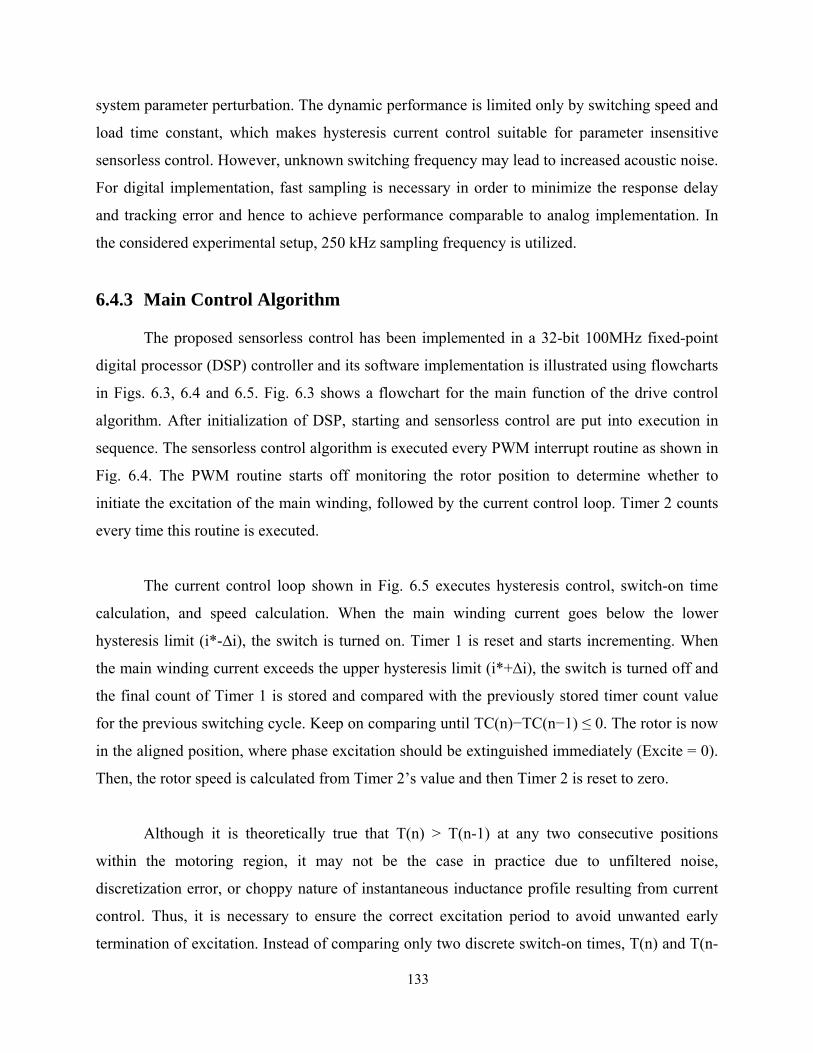
133
system parameter perturbation. The dynamic performance is limited only by switching speed and
load time constant, which makes hysteresis current control suitable for parameter insensitive
sensorless control. However, unknown switching frequency may lead to increased acoustic noise.
For digital implementation, fast sampling is necessary in order to minimize the response delay
and tracking error and hence to achieve performance comparable to analog implementation. In
the considered experimental setup, 250 kHz sampling frequency is utilized.
6.4.3 Main Control Algorithm
The proposed sensorless control has been implemented in a 32-bit 100MHz fixed-point
digital processor (DSP) controller and its software implementation is illustrated using flowcharts
in Figs. 6.3, 6.4 and 6.5. Fig. 6.3 shows a flowchart for the main function of the drive control
algorithm. After initialization of DSP, starting and sensorless control are put into execution in
sequence. The sensorless control algorithm is executed every PWM interrupt routine as shown in
Fig. 6.4. The PWM routine starts off monitoring the rotor position to determine whether to
initiate the excitation of the main winding, followed by the current control loop. Timer 2 counts
every time this routine is executed.
The current control loop shown in Fig. 6.5 executes hysteresis control, switch-on time
calculation, and speed calculation. When the main winding current goes below the lower
hysteresis limit (i*-∆i), the switch is turned on. Timer 1 is reset and starts incrementing. When
the main winding current exceeds the upper hysteresis limit (i*+∆i), the switch is turned off and
the final count of Timer 1 is stored and compared with the previously stored timer count value
for the previous switching cycle. Keep on comparing until TC(n)−TC(n−1) ≤ 0. The rotor is now
in the aligned position, where phase excitation should be extinguished immediately (Excite = 0).
Then, the rotor speed is calculated from Timer 2’s value and then Timer 2 is reset to zero.
Although it is theoretically true that T(n) > T(n-1) at any two consecutive positions
within the motoring region, it may not be the case in practice due to unfiltered noise,
discretization error, or choppy nature of instantaneous inductance profile resulting from current
control. Thus, it is necessary to ensure the correct excitation period to avoid unwanted early
termination of excitation. Instead of comparing only two discrete switch-on times, T(n) and T(n-

134
1), comparing two averaged switch-on times can solve this problem. First, take two moving
averages of several (five cycles were used here) switch-on times: 1) average from T(n) to T(n-4)
and 2) average from T(n-1) to T(n-5), and then compare two averaged switch-on times.
Fig. 6.3. Flowcharts for the main function algorithm

135
Fig. 6.4. Flowcharts for the PWM interrupt routine
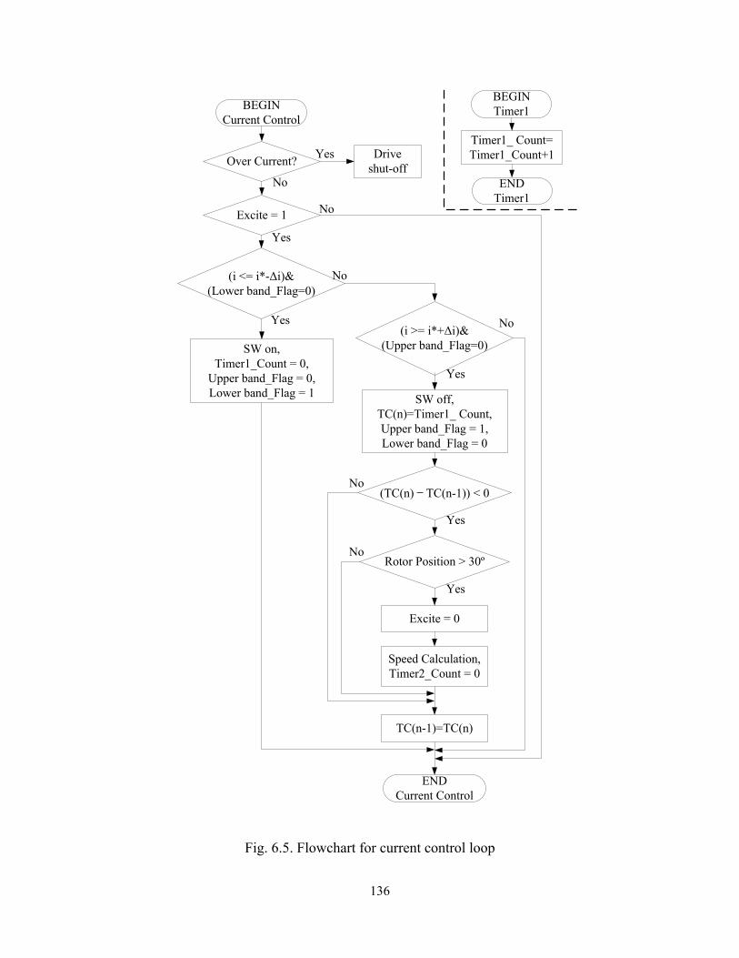
136
Fig. 6.5. Flowchart for current control loop
BEGINCurrent Control
Over Current? Drive shut-off
Yes
Excite = 1
No
(i <= i*-Δi)&(Lower band_Flag=0)
Yes
No
No
SW on,Timer1_Count = 0,
Upper band_Flag = 0,Lower band_Flag = 1
(i >= i*+Δi)&(Upper band_Flag=0)
SW off,TC(n)=Timer1_ Count,Upper band_Flag = 1,Lower band_Flag = 0
(TC(n) – TC(n-1)) < 0
Rotor Position > 30º
Excite = 0
Speed Calculation,Timer2_Count = 0
ENDCurrent Control
Yes
No
No
Yes
Yes
No
TC(n-1)=TC(n)
BEGINTimer1
ENDTimer1
Timer1_ Count=Timer1_Count+1
Yes
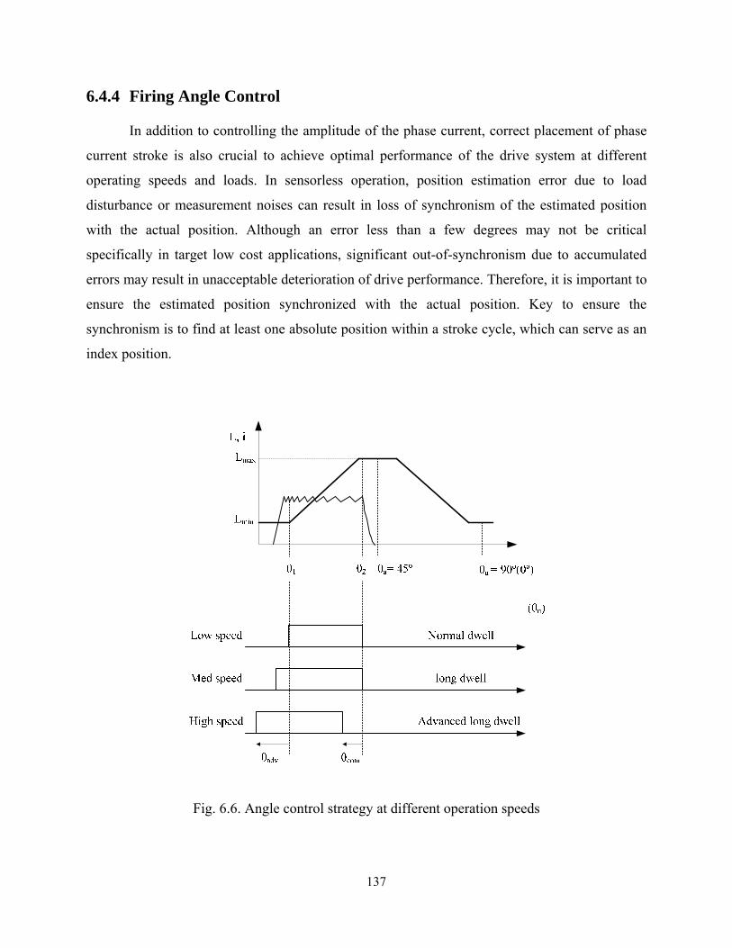
137
6.4.4 Firing Angle Control
In addition to controlling the amplitude of the phase current, correct placement of phase
current stroke is also crucial to achieve optimal performance of the drive system at different
operating speeds and loads. In sensorless operation, position estimation error due to load
disturbance or measurement noises can result in loss of synchronism of the estimated position
with the actual position. Although an error less than a few degrees may not be critical
specifically in target low cost applications, significant out-of-synchronism due to accumulated
errors may result in unacceptable deterioration of drive performance. Therefore, it is important to
ensure the estimated position synchronized with the actual position. Key to ensure the
synchronism is to find at least one absolute position within a stroke cycle, which can serve as an
index position.
Fig. 6.6. Angle control strategy at different operation speeds

138
There are two index positions within a stroke cycle as shown in Fig. 6.6:
1) Rotor position where the inductance starts increasing (The rotor pole starts
overlapping with the stator pole): θ1
2) Rotor position where the inductance becomes constant at its maximum value (The
rotor pole becomes completely overlapped with the stator pole): θ2
Fig. 6.6 depicts the firing angle control scheme employed in this drive system. Idealized
current pulses correspond to optimal excitation at different speed ranges. Angle control is carried
out so that optimal current excitation at each different operating speed as well as smooth
transition from low- to high-speed operation is achieved, and it is explained as follows.
Low speed
In low speeds, θ2 where the inductance reaches the maximum value is used as an index
position. This angle can be used as a default turn-off angle, θoff. Turn-on angle can be determined
using the motor geometry such that the unaligned position, θu (mid-point at maximum inductance
region) and aligned position, θa (mid-point at minimum inductance region) are shifted 45° each
other. The turn-on angle is determined by a position advanced by 45° from θ2, which is slightly
advanced than θ1. No further advancing of either turn-on or turn-off is executed in this speed
range so that dwell angle remains constant as the amplitude of current command is the main
control parameter in low speeds.
Medium speed
As the speed increases, the current cannot rise fast enough to reach its commanded value
at the onset of positive inductance slope, i.e., θ1 due to the effect of back-EMF and finite rise
time. The excitation must be initiated earlier than θ1 and hence the turn-on angle should be
advanced with respect to the operating speed. The index position is still θ2 in this speed range
and θ2 is used as a turn-off angle which still remains the same.
High speed
As the speed even further increases, the back-EMF becomes comparable to dc link
voltage, hence requiring further advancing the turn-on. In addition, the turn-off angle also needs

139
to be advanced to avoid negative torque production. Therefore, the index angle, θ2 cannot be
used as the constant turn-off angle as it is adjusted in this speed range. θ1 is then used as an index
angle. From detected θ1, both turn-on and turn-off angles for the next cycle can be determined.
6.5 Simulation Verification
Fig. 6.7 shows simulation results for the proposed sensorless method implemented on the
single-switch-based SRM running at 1800 r/min with 4A current command. Waveforms of the
main phase inductance, gate signal for switch S1, main phase current, timer count for switch-on
time, and estimated rotor position (electrical degree) are plotted. The timer count for each
switch-on time varies with respect to the rotor position such that it increases along with the
positive inductance slope but decreases with the negative inductance slope. Hence, the aligned
position is detected from the transition of the timer count from incrementing to decrementing
count. It can be seen that the timer count correlates with the actual inductance profile and hence
with the estimated rotor position.
Fig. 6.7. Simulation results for the rotor position estimation
Mai
n ph
ase
Cur
rent
(A)
Switc
h-on
time
coun
tEs
timat
ed ro
tor
posi
tion
(deg
)M
ain
phas
e In
duct
ance
(H)
Gat
e si
gnal
aligned …(θu= 45º)
unaligned(θa= 90º (0º)
… aligned(θu= 45º)
Time (s)

140
6.6 Experimental Results
Fig. 6.8 shows a block diagram of the experimental drive system including the motor,
drive electronics, and controller. Drive control and sensorless algorithm is implemented in real-
time using a TMS320F2808 DSP controller with 250 kHz sampling frequency for the main phase
current. The dc link voltage is approximately 155V from the rectified ac main. The power
switching devices for the converter are realized with an ultra-fast IGBT and fast-recovery diodes.
The execution of the sensorless starting is shown in Fig. 6.9. The large spike in the main
phase current indicates the induced current pulse by the applied starting pulse with a preset
period of time (1.2ms), which causes the rotor to rotate. The sensorless algorithm is invoked after
165ms to detect the aligned position. The starting may be challenging when the rotor is initially
either at aligned position or midpoint between aligned and unaligned positions. In that case,
multiple pulses should be applied to ensure the sufficient torque production in both main and
auxiliary windings.
Fig. 6.8. Block diagram for experimental drive system

141
Fig. 6.9. Sensorless motor starting from standstill
Fig. 6.10. Measured waveforms when the motor is running at 1800r/min
Hall sensor 1(1V/div)
Gate signal(20V/div)
Time (0.1s/div)
Startingpulse applied.
Main phasecurrent(2A/div)
Hall sensor 2(1V/div)
Sensorless algorithm is started after 165ms.
Main phasecurrent(2A/div)
Gate signal(20V/div)
Hall sensor1(1V/div)
0° 45° 90 °(0 °) 45 °
Motoring region
Time (2ms/div)
Hall sensor2(1V/div)
Motoring region
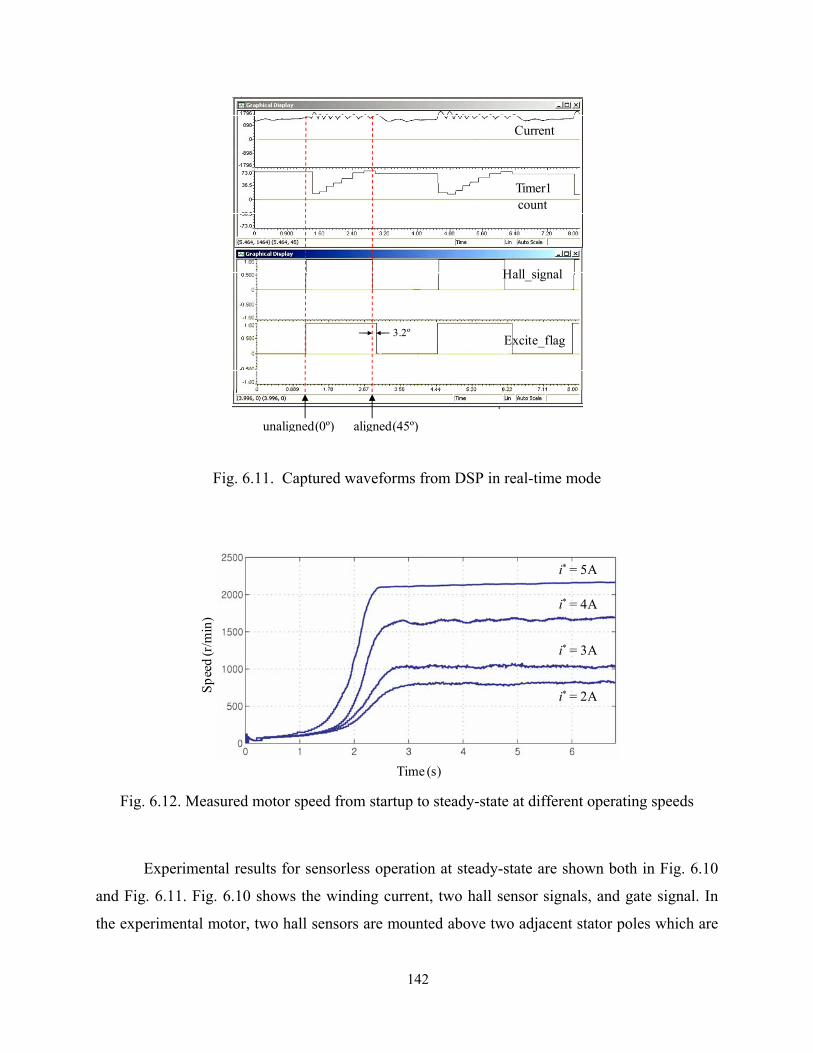
142
Fig. 6.11. Captured waveforms from DSP in real-time mode
Fig. 6.12. Measured motor speed from startup to steady-state at different operating speeds
Experimental results for sensorless operation at steady-state are shown both in Fig. 6.10
and Fig. 6.11. Fig. 6.10 shows the winding current, two hall sensor signals, and gate signal. In
the experimental motor, two hall sensors are mounted above two adjacent stator poles which are
aligned(45º)unaligned(0º)
3.2º
Hall_signal
Excite_flag
Current
Timer1count
Time (s)
Spee
d (r
/min
)
i* = 5A
i* = 4A
i* = 2A
i* = 3A

143
45° shifted each other. Both rising and falling edges of the hall sensor 1 signal indicate the
unaligned position (0°), and both rising and falling edges of the hall sensor 2 signal indicate the
aligned position (45°). Note that only the estimated rotor position and speed are used for drive
control, while the measured hall sensor signals are only a reference to indicate the correct
motoring position. From Fig. 6.10, it can be seen that phase excitation is correctly achieved in
the motoring region and the estimated aligned and unaligned positions are quite comparable to
the actual ones detected by the hall sensors. The current spike at the beginning of excitation
around the unaligned position is due to regenerative energy from the auxiliary winding.
Fig. 6.11 shows the waveforms captured by DSP in real-time mode, which correlates well
with the simulation results in Fig. 6.7. While Hall_signal is logic sum of the hall sensor 1 and 2,
representing the actual excitation period, Excite_flag is the flag signal for the sensorless
algorithm, representing estimated excitation period. They both represent start of phase excitation
at rising edge and end of excitation at falling edge. It can be seen that estimation of the unaligned
position is quite accurate but there is a slight error at the aligned position, which is represented
by the difference between the falling edges of the hall sensor signal and the excitation period flag
about 3.2°. This is due to the inherent delay of phase commutation since the phase commutation
is initiated after the unaligned position is detected. Another experiment result in Fig. 6.12 was
performed to show the dynamic performance of the sensorless controller at different operating
speeds with different loading, starting from standstill.
6.7 Summary
A new parameter insensitive sensorless control is proposed and experimentally
demonstrated using the single-controllable-switch-based SRM drive. The key conclusions of this
paper are:
1) The proposed scheme is very simple to implement requiring measurement of only phase
current and minimal computation, and does not need any pre-stored lookup table or extra
hardware, which makes this scheme inherently suitable for low cost deployment
144
2) The method is robust to the presence of system parameter variations since it does not
employ an analytical inductance model or a model-based estimator which is sensitive to
the estimation of the motor parameters.
3) Although the method is implemented using a two-phase SRM with the single switch
converter, it can also be implemented with any multi-phase SRM with the conventional
asymmetric converter.It does not limit low speed operation which is quite challenging in
many flux or back-EMF based methods.
4) It is inherently suitable for current controlled operation rather than single-pulse operation
where chopping is not possible.
5) The drive system has only one controllable switch and two diodes in total for driving the
two-phase SRM, hence making it very compact and inexpensive. The considered SRM
drive in conjunction with the proposed sensorless scheme can offer an attractive solution
for brushless variable speed drives in low-cost, high-volume applications such as home
appliances.
145
Chapter 7
Conclusions
This thesis has presented three different SRM drives that can be viable alternatives for
conventional universal motors or permanent magnet DC brushes motors in high volume
applications such as fans, pumps, home appliance drives. Two novel converters have been
proposed. The drive systems are realized using two-phase motors and the proposed converters.
The operation principles, derivation of system equations, converter modeling, as well as design
consideration for all three different converter-based drives have been discussed. Simulation and
experimental tests have also been conducted to validate feasibility of the drive systems. All of
those drives have been validated based on conventional sensor-based speed control scheme. To
achieve further cost reduction, a new parameter insensitive sensorless control has been proposed
and partly implemented with the proposed drives. In addition, optimal efficiency control in
single-pulse mode with optimal number of winding turns has also been presented to obtain
optimal performance. The scope of this research is to develop low-cost, high-efficiency,
brushless variable speed drives system targeting low-cost, high-volume application, such as
home appliances markets. Three different two-phase SRM drives are designed and implemented
with a focus on minimum electronics and simple yet efficient drive control to meet the
demanding requirement from home appliance market in terms of cost, efficiency, input power
factor.

146
The followings are the summary of the key contributions made in this research:
• Analysis, design, simulation, and experimental verification of the proposed two-
phase, single-controllable-switch-converter based SRM drive.
• Analysis, design, simulation, and experimental verification of the proposed two-
phase, two-controllable-switch-converter based SRM drive
• Analysis, design, simulation, and experimental validation of the proposed two-phase,
two-switch based, high-speed SRM drive.
• Optimal efficiency control in single-pulse mode with optimal number of winding
turns.
• Parameter insensitive position sensorless control and its implementation with the
above proposed drive systems to achieve further cost reduction.
• Study of effect of input power factor correction and its implementation using only
passive components and the drive structure without external electronics.
• Comparative study of the proposed drive systems, along with the existing brush-
commutator or permanent magnet motors to provide guideline for their selection
based on the requirement for their intended applications.
147
Bibliography
[1] R. Krishnan, “Whither motor drives: A case study in switched reluctance motor drives," Electrical Machines and Systems, 2007. ICEMS, pp.472-480, 8-11 Oct. 2007.
[2] V.R. Stefanovic, “Opportunities in Motor Drive Research – A View From Industry,” IEEE IECON, Proc. Record, pp.xxxvii-xlv, Orlando, 1995
[3] H. N. Hickok, “Adjustable speed—a tool for saving energy losses pumps, fans, blowers, and compressors,” IEEE Trans. Ind. Applicat., vol. 21, pp. 124–136, Jan./Feb. 1985.
[4] M. Chomat and T.A. Lipo, “Adjustable-Speed Single-Phase IM Drive With Reduced Number of Switches,” IEEE Trans. On IAS, Vol.39, No.3, pp. 819-825, May/Jun. 2003
[5] J.M. Bourgeois, J.M. Charreton, and P. Rault, “Improved Universal Motor Drive,” Application Note, AN422, ST Microelectronics, 1994.
[6] A.S. Ba-thunya, R. Khopkar, K. Wei, and H.A. Toliyat, “Single phase induction motor drives-a literature survey,” Electric Machines and Drives Conference, IEMDC 2001, IEEE International, vol., no., pp.911-916
[7] B. Welchko and T.A. Lipo, “A Novel Variable-Frequency Three-Phase Induction Motor Drive System Using Only Three Controlled Switches,” IEEE Trans. On IAS, Vol.37, No.6, pp. 1739-1745, Nov/Dec. 2001.
[8] R. Krishnan, “A Novel Single-Switch-Per-Phase Converter Topology for Four-Quadrant PM Brushless DC Motor Drive,” IEEE Trans. On IAS, Vol.33, No.5, pp. 1154-1161, Sep./Oct. 1997
[9] R. Krishnan, “An energy-efficiency-enhanced switched reluctance motor [From Mind To Market],” Industrial Electronics Magazine, IEEE , vol.1, no.1, pp.4-6, Spring 2007
[10] R. Krishnan, Switched Reluctance Motor Drives, CRC Press, 2001.
[11] M. Barnes, A.M. Michaelides, C. Pollock, “The design and performance of a self-starting 2-phase switched reluctance drive”, Power Electronics and Variable Speed Drives, 6th Int’l Conf. (Publ. No. 429), pp. 419 – 423, 1996
[12] R. Hamdy, J. Fletcher, and B.W. Williams, “Bidirectional Starting of a Symmetrical Two-Phase Switched Reluctance Machine,” IEEE Trans. On Energy Conversion, Vol. 15., No. 2, June, 2000
[13] S. Vukosavic, and V. R. Stefanovic, “SRM inverter topologies: a comparative evaluation,” IEEE Trans. On Industry Applications,Vol. 27, No. 6, 1991 pp. 1034 – 1047
[14] C. Pollock and B.W. Williams, “Power Converter Circuits for Switched Reluctance Motors with the Minimum Number of Switches,” IEE Proc. Vol. 137, Pt. B No. 6., 1990
[15] A. Ayob, V. Pickert, H. Slater, “Overview of low cost converters for single-phase switched reluctance motors,” 2005 European Conference on Power Electronics and Applications, 11-14, Sept. 2005

148
[16] S. Mir, “Classification of SRM Converter Topologies for Automotive Application,” SAE Technical Paper Series Number 000-01-0133, March 6-9, 2000.
[17] M. Barnes and C. Pollock, “Selecting power electronic converters for single phase switched reluctance motors,” in Proc. Power Electronics and Variable Speed Drives,1998, pp. 527-531.
[18] P.J. Lawrenson, J.M. Stephenson, P.T. Blenkinsop, J. Corda, and N.N. Fulton, “Variable speed reluctance motors,” IEEE Proc. Electrical Power Appl. B, 127(4), 253-265, 1980.
[19] Davis, R.M. and R.J. Blake, “Inverter drive for switched reluctance motor circuits and component ratings,” IEE Proc., 126–136, 1981.
[20] T.J.E. Miller, “Converter volt-ampere requirements of the switched reluctance motor drive,” IEEE Trans. Industrial Application., Vol. 21, No. 5, pp.1136-1144, 1985
[21] R. Krishnan, S. Aravind, and P. Materu, “Computer-aided design of electrical machines for variable speed applications,” Proceedings, IEEE-IECON’87, Cambridge, pp756-763.
[22] T.J.E. Miller, “Brushless reluctance motor drives,” IEE Power Engineering Journal, Vol. 1, pp.283-289.
[23] R. Krishnan, and P. Materu, “Analysis and design of a new converter topology for switched reluctance motor drives, IEEE IAS, 1181–1185, 1989.
[24] R. Krishnan, P. Materu, “Design of a Single-Switch-per-Phase Converter for Switched Reluctance Motor Drives,” IEEE Trans. on Industrial Electronics, vol.37, No.6, Dec.1990
[25] T.J.E Miller, Switched Reluctance Motors and Their Control, Magna Physics Publishing/Clarendon Press, Oxford, 1993
[26] M. Ehsani, I. Husain, K.R. Ramani, and J.H Galloway, “Dual-decay converter for switched reluctance motor drives in low-voltage applications,” IEEE Trans. Power Electronics, 1993, 8, (2), pp. 224-230.
[27] M. Eshani,J.T. Bass,T.J.E. Miller, and R.L. Steigerwald, “Development of a unipolar converter for variable reluctance motor drives, ” IEEE Trans. On Ind. App., Vol.23, No.3, pp.545-553, 1987.
[28] S. Mir, I. Husain, and M. Elbuluk, “Energy-Efficient C-dump Converters for Switched Reluctance Motors,” IEEE Trans. on Power Electronics, Volume 12, Issue 5, Sept. 1997
[29] V.V. Deshpande, J.Y. Lim, “New converter configurations for switched reluctance motors wherein some windings operate on recovered energy,” Industry Applications, IEEE Transactions on , vol.38, no.6, pp. 1558-1565, Nov/Dec 2002
[30] R. Krishnan, “Method, apparatus, and system for drive control, power conversion, and start-up control in an SRM or PMBDCM drive system,” US patent, Pub. No.:US 2005/ 0146304 A1, Jul.7, 2005
[31] R. Krishnan, S. Y. Park, and K. S. Ha, “Theory and Operation of a Four-Quadrant Switched Reluctance Motor Drive with a Single Controllable Switch-The Lowest Cost Brushless Motor Drive”, IEEE Trans. on IAS, Vol.41, No.4, pp.1047-55, Aug 2005
[32] R. Krishnan, “Single controllable switch based SRM drive system”, Intellectual property of Ramu Inc., 2008. (Patent pending).

149
[33] Krishnan Ramu, “Apparatus for drive control, power conversion, and start-up control in a PMBDCM or two phase SRM Drive system”, Patent pending, Pub.No: US 2005/0116679 A1, June 2, 2005.
[34] N.Mohan, T.M. Undeland, and W.P.Robbins, Power Electronics: Converters, Applications, and Design, John Wiley & Sons Inc., 2nd Edition, 1995
[35] W. Thong and C. Pollock, “Two Phase Switched Reluctance Drive with Voltage Doubler and Low DC link Capacitance” in Proc. IEEE IAS Conference, vol. 3, pp. 2155-2159 Oct. 2005.
[36] K. Ha, C. Lee, J. Kim, R. Krishnan, and S. G. Oh, “Design and development of brushless variable speed drive for low cost and high efficiency,” in Proc. IEEE Industry Applications Conference, Vol. 4, pp.1649-1656, Oct. 2006.
[37] MacMinn, S.R., and Sember, J.W., “Control of a Switched-Reluctance Aircraft Engine Starter-Generator over a Very Wide Speed Range,” in Proc. IECEC, Aug. 6-11, 1989.
[38] Kjaer, P. Nielsen, L. Andersen, and F. Blaabjerg, “A New Energy Optimizing Control Strategy for Switched Reluctance Motors,” IEEE Trans. Ind. Appl., vol. 31, no. 5, pp. 1088–1095, Sep./Oct. 1995.
[39] I. Kioskeridis and C. Mademlis, “Maximum Efficiency Operation of Switched Reluctance Motor Drives”, IEEE Trans. Energy Conversion, Vol. 20, No. 4,Dec.2005
[40] C. Mademlis and I. Kioskeridis, “Performance Optimization in Switched Reluctance Motor Drives with Online Commutation Angle Control,” IEEE Trans. Energy Conv., vol. 18, no. 3, pp. 448–457, Sep. 2003.
[41] Y.Sozer, D.A.Torrey, and E.Mese, “Automatic control of excitation parameters for switched reluctance motor drives,” in Proc. Applied Power Electron. Conf and Exposition, vol. 1, pp. 48-56, 2002.
[42] J.J Cribble, P.C. Kjaer, and T.J.Miller, “Optimal commutation in average torque control of switched reluctance motors”, IEE Proc. Power Appl. Vol. 146, No.1,January 1999
[43] J. Corda, “Search for Optimum Number of Turns of Switched Reluctance Motor”, in Proc. Intl. Power Electronics Congress, pp. 241 – 245, Oct. 1996.
[44] J.P. Lyons, S.R. MacMinn, and M.A. Preston, “Flux/current methods for SRM rotor position estimation,” Proc. IEEE-IAS Annu. Meeting, 1991, pp.482-487
[45] N. H. Mvungi and J. M. Stephenson, “Accurate sensorless rotor position detection in an SR motor,” in Proc.s European Power Electron. Conf., Vol. I, 1991, pp. 390-393.
[46] K.M. Richardson, C. Pollock, and J. O. Flower, “Design and Performance of a Rotor Position Sensing System for a Switched Reluctance Machine Propulsion Unit,” in Proc. IEEE-IAS Annu. Meeting., 1996, pp.168-173
[47] H. Y. Yang, J.G. Kim, Y.C. Lim, S. K. Jeong, and Y. G. Jung, “Position detection and drive of a toroidal switched reluctance motor(TSRM) using search coils”, IEE Proc. Electric Power Appl., 2004, pp.377-384
[48] I. Husain, S. Sodhi, and M. Ehsani, “A sliding mode observer basedcontroller for switched reluctance motor drives,” in Proc. IEEE-IAS Annu. Meeting, 1994, pp. 635–643.
150
[49] Y. J. Zhan, C. C. Chan, and K. T. Chau, “A novel sliding-mode observer for indirect position sensing of switched reluctance motor drives,” IEEE Trans. Ind. Electron., vol. 46, pp. 390–397, Apr. 1999.
[50] F. Blaabjerg, L. Christensen, S. Hansen, J. P. Kristofferson, and P. O. Rasmussen, “Sensorless control of a switched reluctance motor with variable-structure observer,” Electromotion, vol. 3, no. 3, pp. 141–152, July 1996.
[51] A. D. Cheok, and N. Etugrul, “High Robustness of an SR Motor Angle Estimation Algorithm Using Fuzzy Predictive Filters and Heuristic Knowledge-Based Rules”, IEEE Trans.,1999, Ind. Electron, Vol. 46, pp.904-916
[52] E. Mese, and D. A. Torrey, “An Approach for Sensorless Position Estimation for Switched Reluctance Motors Using Artifical Neural Networks”, IEEE Trans., on Power Electron., 2002, pp.66-75
[53] S. Paramasivam, S. Vijayan, M. Vasudevan, R. Arumugam, and R. Krishnan, “Real-Time Verification of AI Based Rotor Position Estimation Techniques for a 6/4 Pole Switched Reluctance Motor Drive”, IEEE Trans. on Magnetics, Vol. 43, No. 7, July 2007
[54] C. Hudson, N. S. Lobo, and R. Krishnan, "Sensorless control of single switch based switched reluctance motor drive using neural network," in IECON 2004. 30th Annual Conference of IEEE, 2004, pp. 2349-2354 Vol. 3.
[55] G. Suresh, B. Fahimi, K. M. Rahman, and M. Ehsani, “Inductance based position encoding for sensorless SRM drives,” in Proc. IEEE Power Electronics Specialists Conf., vol. 2, 1999, pp. 832–837.
[56] H. Gao, F.R. Salmasi, and M. Ehsani, “Inductance model-based sensorless control of the switched reluctance motor drive at low speed”, IEEE Trans. on Power Electron., Nov. 2004. Vol. 19, pp: 1568- 1573
[57] S.R.MacMinn, W.J. Rzesos, P.M. Szczesny, and T.M. Jahns, “Application of sensor integration techniques to switched reluctance motor drives”, IEEE Trans. on Ind. Appl, 1992, Vol.28, No.6, pp. 1339-1344.
[58] M. Ehsani, I. Husain, and A. Kulkarni, “Elimination of discrete position sensor and current sensor in switched reluctance motor drives”, IEEE Trans. on Industry Appl., 1992,Vol. 28, No.1, pp. 128-135.
[59] P.P. Acarnley, R.J. Hill, and C.W. Hooper, “Detection of rotor position in stepping and switched reluctance motors by monitoring of current waveforms. IEEE Trans. Ind. Electron.”, 1985, Vol. 32, No. 3, pp. 215-222.
[60] S.K. Panda, and G.A.J. Amaratunga, “Analysis of the waveform detection technique for indirect rotor position sensing of switched reluctance motor drives,” IEEE Trans. on Energy Conversion, 1991,Vol. 6 , No. 3, pp. 476-483.
[61] G. Gallegos-Lopez, P. C. Kjaer, and T. J. E. Miller, “Anew sensorless method for switched reluctance motor drives”, IEEETrans. on Ind. Appl., Vol.34, No.4. pp. 832-840, July/August 1998.
Top Related