


Languages
Pages
Legal

V A C U U M
An important selection of standard vacuum solutions, from vacuum pumps and cups to
switches and accessories, including the dual module vacuum generator. At
www.norgren.com, you can download additional technical information. For more
information on a specific actuator or actuator series, simply go to the web address
printed under the online icons at the bottom of the following actuator product pages.
www.norgren.com
N o r g r e n v a c u u m
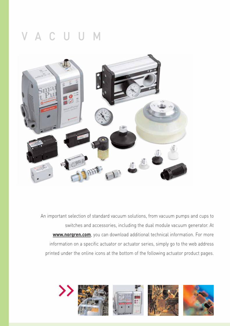
Vacuum products M/58112Single stage vacuum pumps
Page 2 - 296
M/58028/VB, ... /VFVacuum switches (pneumatic)
M/58102Multi stage vacuum pumps
Page 2 - 298
M/58300, M/58400Flat and bellows cupsØ 6 ... 150 mm
Page 2 - 306 Page 2 - 302
M/58024/VB, .../VFM/58027/VAP/P../VAN/PVacuum switches(electrical/electronic)
Page 2 - 303
VMAA Smart Pump®
Dual module vacuum generator
Page 2 - 300
VACUUM ACCESORIES
Page 2 - 304
2-001
www.norgren.com/info/en2-002
For further information
2-002
Very high induced air capacity
14% lower air consumption thancomparable single stage units
No wearing parts
Compatible with a wide range ofvacuum line contaminants
Allows direct connection of suction cups and piped exhaustfacility
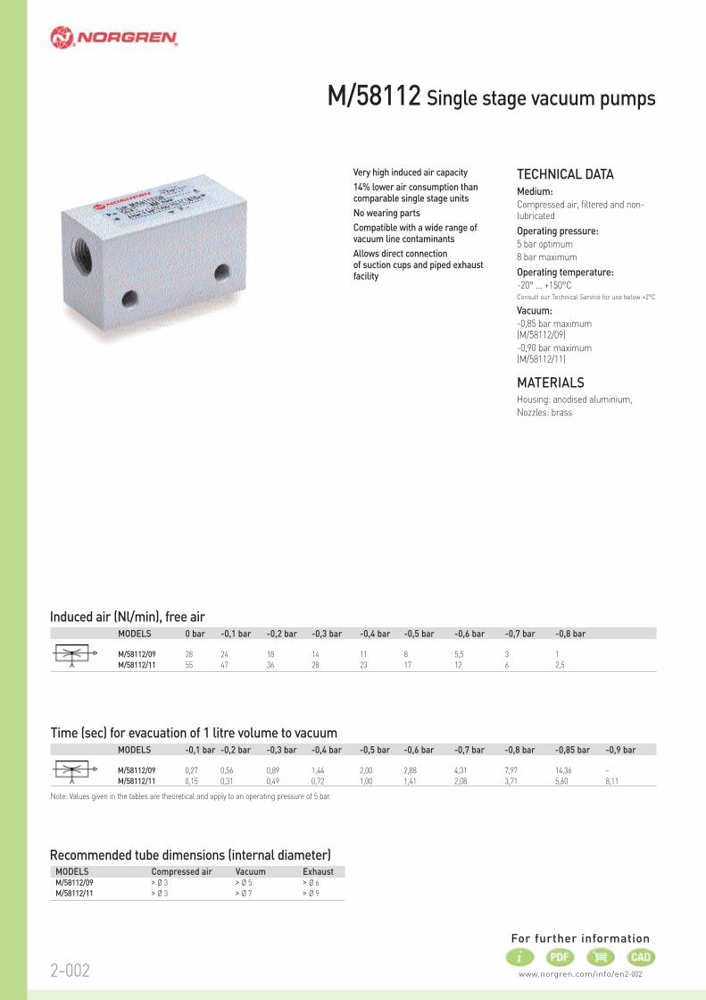
M/58112 Single stage vacuum pumps
Induced air (Nl/min), free air
Time (sec) for evacuation of 1 litre volume to vacuum
MODELS 0 bar -0,1 bar -0,2 bar -0,3 bar -0,4 bar -0,5 bar -0,6 bar -0,7 bar -0,8 bar
M/58112/09 28 24 18 14 11 8 5,5 3 1
M/58112/11 55 47 36 28 23 17 12 6 2,5
MODELS -0,1 bar -0,2 bar -0,3 bar -0,4 bar -0,5 bar -0,6 bar -0,7 bar -0,8 bar -0,85 bar -0,9 bar
M/58112/09 0,27 0,56 0,89 1,44 2,00 2,88 4,31 7,97 14,36 –
M/58112/11 0,15 0,31 0,49 0,72 1,00 1,41 2,08 3,71 5,60 8,11
Note: Values given in the tables are theoretical and apply to an operating pressure of 5 bar.
Recommended tube dimensions (internal diameter)MODELS Compressed air Vacuum ExhaustM/58112/09 > Ø 3 > Ø 5 > Ø 6
M/58112/11 > Ø 3 > Ø 7 > Ø 9
TECHNICAL DATAMedium:
Compressed air, filtered and non-lubricated
Operating pressure:
5 bar optimum
8 bar maximum
Operating temperature:
-20° ... +150°CConsult our Technical Service for use below +2°C
Vacuum:
-0,85 bar maximum (M/58112/09)
-0,90 bar maximum (M/58112/11)
MATERIALSHousing: anodised aluminium,
Nozzles: brass

2-0032-003
CHARACTERISTICS (all values given apply to an atmospheric pressure of 1013 mbar)
Air consumption
Operating pressure Operating pressure
Vacuum
BASIC DIMENSIONS
M/58112/09 (weight: 0,054 kg) M/58112/11 (weight: 0,157 kg)
(Nl / min.)
www.norgren.com/info/en2-004
For further information
2-004
CHARACTERISTICSInduced air (Nl/min), free air
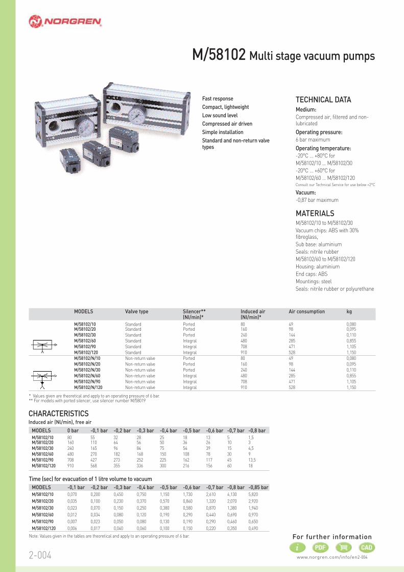
Fast response
Compact, lightweight
Low sound level
Compressed air driven
Simple installation
Standard and non-return valvetypes
TECHNICAL DATAMedium:
Compressed air, filtered and non-lubricated
Operating pressure:
6 bar maximum
Operating temperature:
-20°C ... +80°C for
M/58102/10 ... M/58102/30
-20°C ... +60°C for
M/58102/60 ... M/58102/120Consult our Technical Service for use below +2°C
Vacuum:
-0,87 bar maximum
MATERIALSM/58102/10 to M/58102/30
Vacuum chips: ABS with 30%fibreglass,
Sub base: aluminium
Seals: nitrile rubber
M/58102/60 to M/58102/120
Housing: aluminium
End caps: ABS
Mountings: steel
Seals: nitrile rubber or polyurethane
Time (sec) for evacuation of 1 litre volume to vacuum
M/58102 Multi stage vacuum pumps
MODELS -0,1 bar -0,2 bar -0,3 bar -0,4 bar -0,5 bar -0,6 bar -0,7 bar -0,8 bar -0,85 bar
M/58102/10 0,070 0,200 0,450 0,750 1,150 1,730 2,610 4,130 5,820
M/58102/20 0,035 0,100 0,230 0,370 0,570 0,860 1,320 2,070 2,920
M/58102/30 0,023 0,070 0,150 0,250 0,380 0,580 0,870 1,380 1,940
M/58102/60 0,012 0,034 0,080 0,120 0,190 0,290 0,440 0,690 0,970
M/58102/90 0,007 0,023 0,050 0,080 0,130 0,190 0,290 0,460 0,650
M/58102/120 0,006 0,017 0,040 0,060 0,100 0,150 0,220 0,350 0,490
Note: Values given in the tables are theoretical and apply to an operating pressure of 6 bar.
MODELS 0 bar -0,1 bar -0,2 bar -0,3 bar -0,4 bar -0,5 bar -0,6 bar -0,7 bar -0,8 bar
M/58102/10 80 55 32 28 25 18 13 5 1,5 M/58102/20 160 110 64 56 50 36 26 10 3
M/58102/30 240 165 96 84 75 54 39 15 4,5
M/58102/60 480 270 182 168 150 108 78 30 9
M/58102/90 708 427 273 252 225 162 117 45 13,5
M/58102/120 910 568 355 336 300 216 156 60 18
MODELS Valve type Silencer** Induced air Air consumption kg(NI/min)* (NI/min)*
M/58102/10 Standard Ported 80 49 0,080M/58102/20 Standard Ported 160 98 0,095
M/58102/30 Standard Ported 240 144 0,110
M/58102/60 Standard Integral 480 285 0,855
M/58102/90 Standard Integral 708 471 1,105
M/58102/120 Standard Integral 910 528 1,150
M/58102/N/10 Non-return valve Ported 80 49 0,080
M/58102/N/20 Non-return valve Ported 160 98 0,095
M/58102/N/30 Non-return valve Ported 240 144 0,110
M/58102/N/60 Non-return valve Integral 480 285 0,855
M/58102/N/90 Non-return valve Integral 708 471 1,105
M/58102/N/120 Non-return valve Integral 910 528 1,150
* Values given are theoretical and apply to an operating pressure of 6 bar.** For models with ported silencer, use silencer number M/58019
2-0052-005
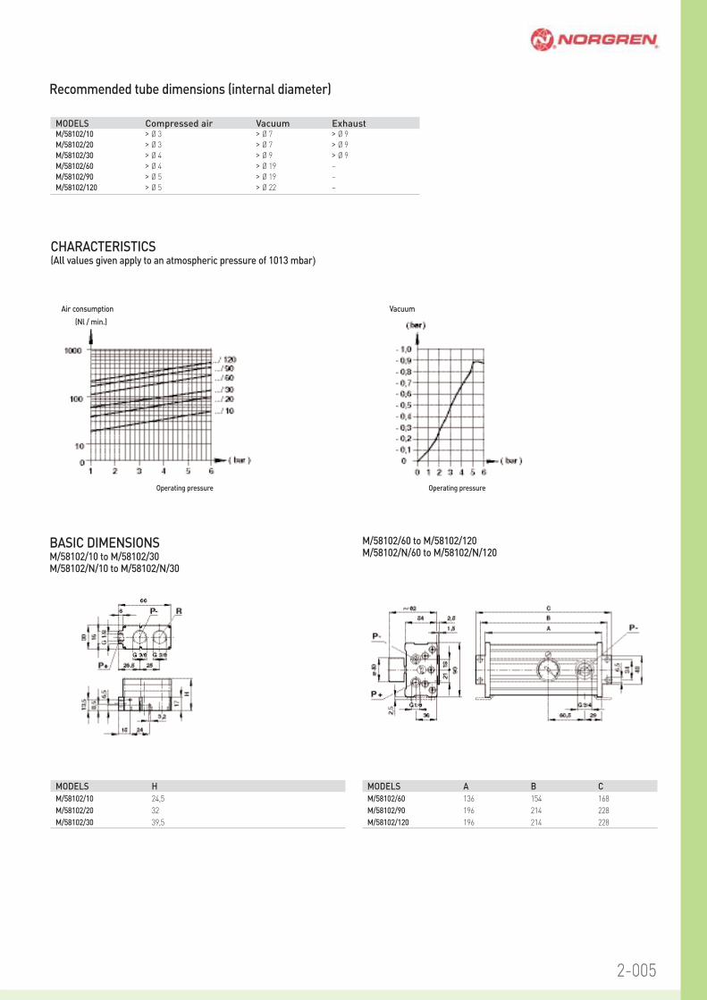
MODELS Compressed air Vacuum ExhaustM/58102/10 > Ø 3 > Ø 7 > Ø 9
M/58102/20 > Ø 3 > Ø 7 > Ø 9
M/58102/30 > Ø 4 > Ø 9 > Ø 9
M/58102/60 > Ø 4 > Ø 19 –
M/58102/90 > Ø 5 > Ø 19 –
M/58102/120 > Ø 5 > Ø 22 –
BASIC DIMENSIONSM/58102/10 to M/58102/30M/58102/N/10 to M/58102/N/30
MODELS H
M/58102/10 24,5
M/58102/20 32
M/58102/30 39,5
MODELS A B C
M/58102/60 136 154 168
M/58102/90 196 214 228
M/58102/120 196 214 228
M/58102/60 to M/58102/120M/58102/N/60 to M/58102/N/120
CHARACTERISTICS (All values given apply to an atmospheric pressure of 1013 mbar)
Air consumption
(Nl / min.)
Vacuum
Operating pressureOperating pressure
Recommended tube dimensions (internal diameter)
www.norgren.com/info/en2-006
For further information
2-006
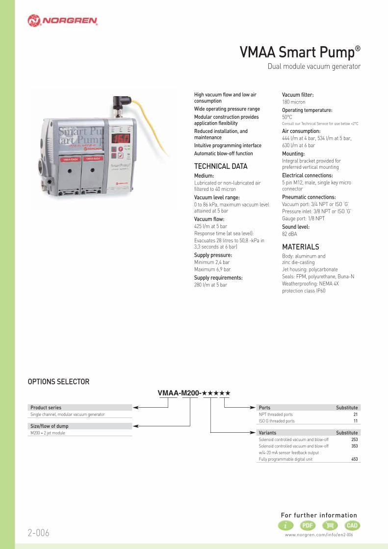
High vacuum flow and low airconsumption
Wide operating pressure range
Modular construction providesapplication flexibility
Reduced installation, andmaintenance
Intuitive programming interface
Automatic blow-off function
TECHNICAL DATAMedium:
Lubricated or non-lubricated airfiltered to 40 micron
Vacuum level range:
0 to 86 kPa, maximum vacuum levelattained at 5 bar
Vacuum flow:
425 I/m at 5 bar
Response time (at sea level):
Evacuates 28 litres to 50,8 -kPa in3,3 seconds at 6 bar)
Supply pressure:
Minimum 2,4 bar
Maximum 6,9 bar
Supply requirements:
280 I/m at 5 bar
OPTIONS SELECTOR
VMAA-M200-˙˙˙˙˙
Product series
Single channel, modular vacuum generator
Size/flow of dump
M200 = 2 jet module
Ports Substitute
NPT threaded ports 21
ISO G threaded ports 11
Variants Substitute
Solenoid controlled vacuum and blow-off 253
Solenoid controlled vacuum and blow-off 353
w/4-20 mA sensor feedback output
Fully programmable digital unit 453
VMAA Smart Pump®
Dual module vacuum generator
Vacuum filter:
180 micron
Operating temperature:
50°CConsult our Technical Service for use below +2°C
Air consumption:
444 l/m at 4 bar, 534 l/m at 5 bar,
630 l/m at 6 bar
Mounting:
Integral bracket provided forpreferred vertical mounting
Electrical connections:
5 pin M12, male, single key microconnector
Pneumatic connections:
Vacuum port: 3/4 NPT or ISO ‘G’
Pressure inlet: 3/8 NPT or ISO ‘G’
Gauge port: 1/8 NPT
Sound level:
82 dBA
MATERIALSBody: aluminum and zinc die-casting
Jet housing: polycarbonate
Seals: FPM, polyurethane, Buna-N
Weatherproofing: NEMA 4X
protection class IP60
2-0072-007
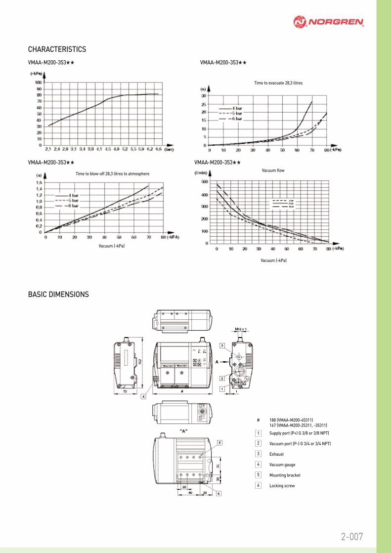
CHARACTERISTICS
VMAA-M200-353˙˙ VMAA-M200-353˙˙
Time to evacuate 28,3 litres
VMAA-M200-353˙˙
Time to blow-off 28,3 litres to atmosphere
Vacuum (-kPa)
VMAA-M200-353˙˙
Vacuum flow
Vacuum (-kPa)
6
5
4
3
2
1
# 188 (VMAA-M200-45311)167 (VMAA-M200-25311, -35311)
Supply port (P+) G 3/8 or 3/8 NPT)
Vacuum port (P-) G 3/4 or 3/4 NPT)
Exhaust
Vacuum gauge
Mounting bracket
Locking screw
BASIC DIMENSIONS
www.norgren.com/info/en2-008
For further information
2-008
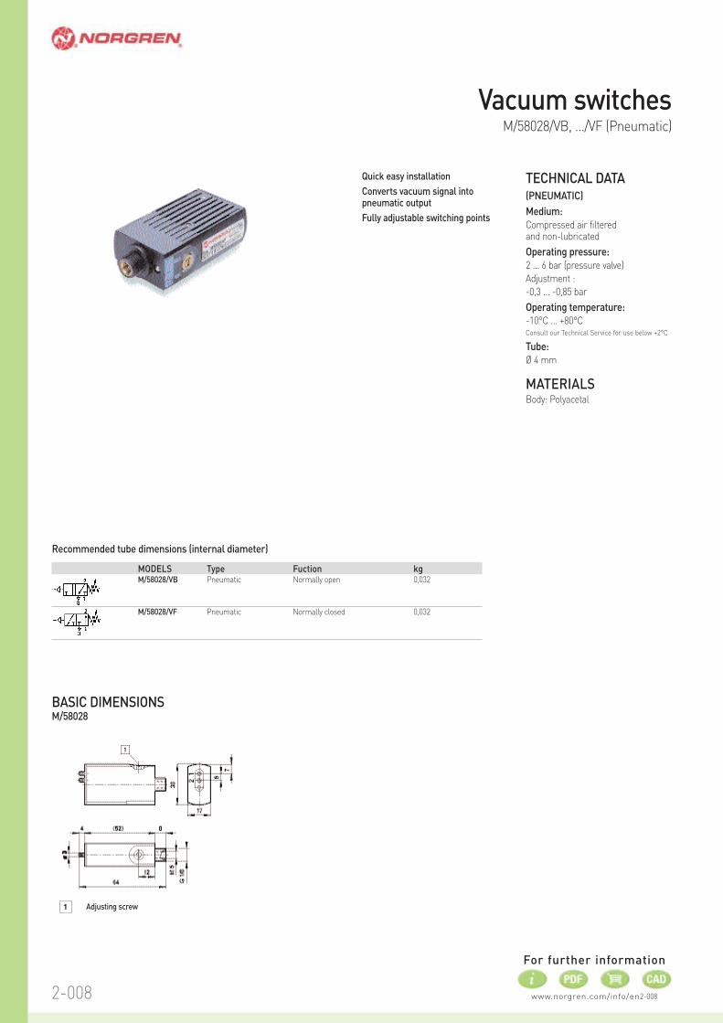
Quick easy installation
Converts vacuum signal intopneumatic output
Fully adjustable switching points
TECHNICAL DATA(PNEUMATIC)
Medium:
Compressed air filtered and non-lubricated
Operating pressure:
2 ... 6 bar (pressure valve)
Adjustment :
-0,3 ... -0,85 bar
Operating temperature:
-10°C ... +80°CConsult our Technical Service for use below +2°C
Tube:
Ø 4 mm
MATERIALSBody: Polyacetal
Vacuum switchesM/58028/VB, .../VF (Pneumatic)
1 Adjusting screw
BASIC DIMENSIONSM/58028
Recommended tube dimensions (internal diameter)
MODELS Type Fuction kgM/58028/VB Pneumatic Normally open 0,032
M/58028/VF Pneumatic Normally closed 0,032
www.norgren.com/info/en2-009
For further information
2-009
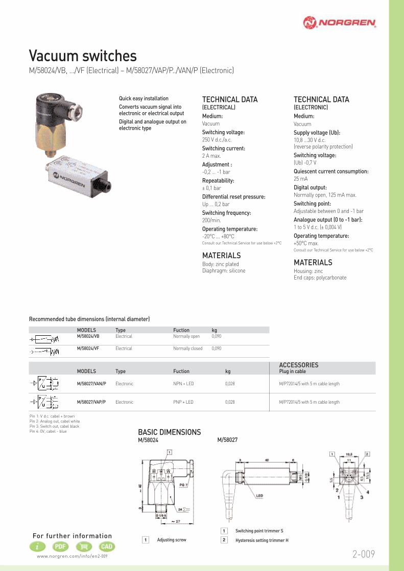
Vacuum switchesM/58024/VB, .../VF (Electrical) – M/58027/VAP/P../VAN/P (Electronic)
Pin 1: V d.c. cabel + brown
Pin 2: Analog out, cabel white
Pin 3: Switch out, cabel black
Pin 4: 0V, cabel - blue
1 Adjusting screw
M/58027BASIC DIMENSIONSM/58024
2
1 Switching point trimmer S
Hysteresis setting trimmer H
Recommended tube dimensions (internal diameter)
MODELS Type Fuction kgM/58024/VB Electrical Normally open 0,090
M/58024/VF Electrical Normally closed 0,090
ACCESSORIESMODELS Type Fuction kg Plug in cable
M/58027/VAN/P Electronic NPN + LED 0,028 M/P72014/5 with 5 m cable length
M/58027/VAP/P Electronic PNP + LED 0,028 M/P72014/5 with 5 m cable length
Quick easy installation
Converts vacuum signal intoelectronic or electrical output
Digital and analogue output onelectronic type
TECHNICAL DATA(ELECTRICAL)
Medium:
Vacuum
Switching voltage:
250 V d.c./a.c.
Switching current:
2 A max.
Adjustment :
-0,2 ... -1 bar
Repeatability:
± 0,1 bar
Differential reset pressure:
Up ... 0,2 bar
Switching frequency:
200/min.
Operating temperature:
-20°C ... +80°CConsult our Technical Service for use below +2°C
MATERIALSBody: zinc platedDiaphragm: silicone
TECHNICAL DATA(ELECTRONIC)
Medium:
Vacuum
Supply voltage (Ub):
10,8 ...30 V d.c. (reverse polarity protection)
Switching voltage:
(Ub) -0,7 V
Quiescent current consumption:
25 mA
Digital output:
Normally open, 125 mA max.
Switching point:
Adjustable between 0 and -1 bar
Analogue output (0 to -1 bar):
1 to 5 V d.c. (± 0,004 V)
Operating temperature:
+50°C max.Consult our Technical Service for use below +2°C
MATERIALSHousing: zincEnd caps: polycarbonate
www.norgren.com/info/en2-010
For further information
2-010
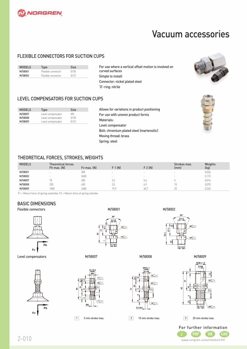
MODELS Type Size
M/58001 Flexible connector G1/8
M/58002 Flexible connector G1/2
MODELS Type Size
M/58007 Level compensator M5
M/58008 Level compensator G1/8
M/58009 Level compensator G1/2
For use where a vertical offset motion is involved oncurved surfaces
Simple to install
Connector: nickel plated steel
‘O’-ring: nitrile
FLEXIBLE CONNECTORS FOR SUCTION CUPS
Allows for variations in product positioning
For use with uneven product forms
Materials:
Level compensator
Bolt: chromium plated steel (martensitic)
Moving thread: brass
Spring: steel
LEVEL COMPENSATORS FOR SUCTION CUPS
MODELS Theoretical forces Strokes max. WeightsFh max. (N) Fv max. (N) F 1 (N) F 2 (N) (mm) (kg)
M/58001 - 300 - - - 0,026
M/58002 - 2600 - - - 0,115
M/58007 70 200 3,3 5,6 5 0,016
M/58008 250 450 3,5 6,9 15 0,070
M/58009 1000 2600 19,9 40,7 25 0,242
THEORETICAL FORCES, STROKES, WEIGHTS
F1 = Return force of spring outstroke, F2 = Return force of spring instroke
Flexible connectors M/58001
Level compensators
M/58002
M/58007 M/58008 M/58009
1 5 mm stroke max. 2 15 mm stroke max. 3 25 mm stroke max.
Vacuum accessories
BASIC DIMENSIONS
2-0112-011
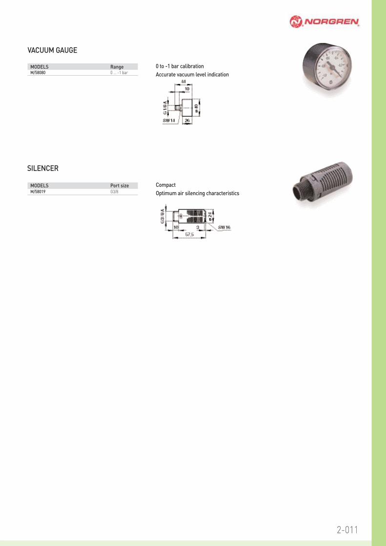
MODELS RangeM/58080 0 ... -1 bar
MODELS Port sizeM/58019 G3/8
0 to -1 bar calibration
Accurate vacuum level indication
VACUUM GAUGE
Compact
Optimum air silencing characteristics
SILENCER

www.norgren.com/info/en2-012
For further information
2-012
Flat cups ideal where minimalmovement is required for pliablematerials
Bellows cups ideal where levelcompensation is required
TECHNICAL DATAMedium:
Vacuum
Operating temperature:
-10°C ... +70°C for nitrile rubber cups-30°C ... +200°C for silicone cupsConsult our Technical Service for use below +2°C
MATERIALSM/58000/01
Cups: nitrile rubber
Connection fittings: aluminium
M/58000/02
Cups: silicone
Connection fittings: aluminium
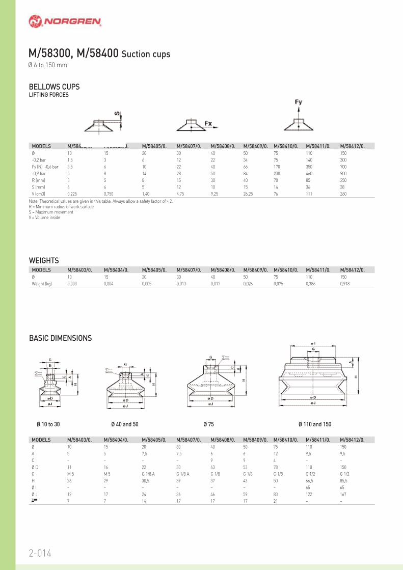
M/58300, M/58400 Suction cupsØ 6 to 150 mm
Fx = μ x Fywhere μ is the frictional coefficient of the material being handled.An approximate guide:Plastic μ = 0,4 to 0,5Steel, oiled μ = 0,1 to 0,3Glass μ = 0,3 to 0,5
MATERIAL CHARACTERISTICS
MODELSFlat Ø Fy (N) R S V
mm -0,2 bar -0,6 bar -0,9 bar (mm) (mm) (cm3) kg
M/58301/* 6 0,5 1,5 2,3 5 1,5 0,017 0,001
M/58302/* 8 1 2,5 3,5 7 1,5 0,041 0,001
M/58303/* 10 1,5 4 6 9 2 0,065 0,001
M/58304/* 15 2,7 8 12 12 4 0,330 0,001
M/58305/* 20 5 15,5 23 13 2 0,500 0,008
M/58306/* 25 9 26,5 40 17,5 2,5 0,750 0,010
M/58307/* 30 11 34 51 26 2,5 1,3 0,012
M/58308/* 40 19 57,5 86 37 3,5 3 0,011
M/58309/* 50 30 91 135 41 4 4,2 0,016
M/58310/* 80 86 260 390 100 6 21 0,058
M/58311/* 120 180 540 810 365 6 82 0,359
M/58312/* 150 280 842 1250 380 9 177 0,59
Bellows
M/58403/* 10 1,5 3,5 5 3 4 0,225 0,003
M/58404/* 15 3 6 8 5 6 0,750 0,004
M/58405/* 20 6 10 14 8 5 1,40 0,005
M/58407/* 30 12 22 28 15 12 4,75 0,013
M/58408/* 40 22 40 50 30 10 9,25 0,017
M/58409/* 50 34 66 84 40 15 26,25 0,026
M/58410/* 75 75 170 230 70 14 76 0,075
M/58411/* 110 140 350 460 85 36 111 0,386
M/58412/* 150 300 700 900 250 38 260 0,918
* Insert material code. nitrile: 01, silicone: 02Note: Theoretical values are given in this table. Always allow a safety factor of > 2.
Nitrile rubber SiliconeWear resistance Good Fair
Oil resistance Excellent Fair
Weather resistance Good Excellent
Ozone resistance Fair Excellent

2-0132-013
FLAT CUPSLIFTING FORCES
BASIC DIMENSIONS
Ø 6 to 30 Ø 40 and 50 Ø 80 Ø 120 and 150
WEIGHTS
Note: Theoretical values are given in this table. Always allow a safety factor of > 2.R = Minimum radius of work surfaceS = Maximum movementV = Volume inside
MODELS M/58301/0. M/58302/0. M/58303/0. M/58304/0. M/58305/0. M/58306/0. M/58307/0. M/58308/0. M/58309/0. M/58310/0. M/58311/0. M/58312
Ø 6 8 10 15 20 25 30 40 50 80 120 150
-0,2 bar 0,5 1 1,5 2,7 5 9 11 19 30 86 180 280
Fy (N) -0,6 bar 1,5 2,5 4 8 15,5 26,5 34 57,5 91 260 540 842
-0,9 bar 2,3 3,5 6 12 23 40 51 86 135 390 810 1250
R (mm) 5 7 9 12 13 17,5 26 37 41 100 365 380
S (mm) 1,5 1,5 2 4 2 2,5 2,5 3,5 4 6 6 9
V (cm3) 0,017 0,041 0,065 0,330 0,500 0,750 1,3 3 4,2 21 82 177
MODELS M/58301/0. M/58302/0. M/58303/0. M/58304/0. M/58305/0. M/58306/0. M/58307/0. M/58308/0. M/58309/0. M/58310/0. M/58311/0. M/58312
Ø 6 8 10 15 20 25 30 40 50 80 120 150
Weight (kg) 0,001 0,001 0,001 0,001 0,008 0,010 0,012 0,011 0,016 0,058 0,359 0,590
MODELS M/58301/0. M/58302/0. M/58303/0. M/58304/0. M/58305/0. M/58306/0. M/58307/0. M/58308/0. M/58309/0. M/58310/0. M/58311/0. M/58312
Ø D 6 8 10 15 20 25 30 40 50 80 120 150
A 4,5 4,5 4,5 4,5 8 8 8 6 6 13 9,5 9,5
C – – – – – – – 9 11 3,5 – –
G M 5 M 5 M 5 M 5 G 1/8 A G 1/8 A G 1/8 A G 1/8 G 1/8 G 1/8 G 1/2 G 1/2
H 15 16 20 21 19,5 20 20,5 23 26 21,5 34,5 41,5
Ø I – – – – – – – 24 26 53 65 65
8 8 8 8 14 14 14 14 14 19 – –
Fx = μ • Fy
2-014
BASIC DIMENSIONS
Ø 10 to 30 Ø 40 and 50 Ø 75 Ø 110 and 150
BELLOWS CUPSLIFTING FORCES
Note: Theoretical values are given in this table. Always allow a safety factor of > 2.R = Minimum radius of work surfaceS = Maximum movementV = Volume inside
WEIGHTS
MODELS M/58403/0. M/58404/0. M/58405/0. M/58407/0. M/58408/0. M/58409/0. M/58410/0. M/58411/0. M/58412/0.
Ø 10 15 20 30 40 50 75 110 150
-0,2 bar 1,5 3 6 12 22 34 75 140 300
Fy (N) -0,6 bar 3,5 6 10 22 40 66 170 350 700
-0,9 bar 5 8 14 28 50 84 230 460 900
R (mm) 3 5 8 15 30 40 70 85 250
S (mm) 4 6 5 12 10 15 14 36 38
V (cm3) 0,225 0,750 1,40 4,75 9,25 26,25 76 111 260
MODELS M/58403/0. M/58404/0. M/58405/0. M/58407/0. M/58408/0. M/58409/0. M/58410/0. M/58411/0. M/58412/0.
Ø 10 15 20 30 40 50 75 110 150
Weight (kg) 0,003 0,004 0,005 0,013 0,017 0,026 0,075 0,386 0,918
MODELS M/58403/0. M/58404/0. M/58405/0. M/58407/0. M/58408/0. M/58409/0. M/58410/0. M/58411/0. M/58412/0.
Ø 10 15 20 30 40 50 75 110 150
A 5 5 7,5 7,5 6 6 12 9,5 9,5
C – – – – 9 9 4 – –
Ø D 11 16 22 33 43 53 78 110 150
G M 5 M 5 G 1/8 A G 1/8 A G 1/8 G 1/8 G 1/8 G 1/2 G 1/2
H 26 29 30,5 39 37 43 50 66,5 85,5
Ø I – – – – – – – 65 65
Ø J 12 17 24 36 46 59 83 122 167
7 7 14 17 17 17 21 – –
M/58300, M/58400 Suction cupsØ 6 to 150 mm
“Our commitment to the waywe do business”Norgren’s commitment to its shareholders,
customers, colleagues, and suppliers is that
collectively and individually we aspire to act
responsibly and to high standards at all times.
Norgren, a responsible business, for more information visit norgren.com
>>NORGREN’S MAIN CONTRIBUTIONto society
‘The value of a successful business’
Our commitment to each of our stakeholders and the main corporate responsibility dimensions of
marketplace, workplace, community and environment can be summed up as follows:
» We all share the responsibility for each other’s health and safety. People are the core of Norgren’s
business and their well being is the key to future success and prosperity.
» We will deal openly, fairly and honestly with suppliers and business partners and not demand of them
standards that we do not apply to ourselves.
» We will be honest, fair and open in our dealings with customers, endeavouring to help them at all times.
When things go wrong, we will resolve problems as quickly and fairly as we can.
» We will observe the laws and regulations of all countries in which we operate, not just in the letter but also
the spirit. We will not countenance bribery, corruption, insider trading or the concealment of conflicts of
interest.
» We are committed to reducing the environmental impact of our business, and to taking social and
environmental issues into account in our processes, practices and the products we supply to customers.
Norgren, a responsible business
Top Related