


Languages
Pages
Legal


VA9104 Series Electric Non-Spring Return Valve Actuators (Asia)Product Bulletin LIT-12013278
Issued January 2021
The VA9104 Series Actuators are direct-mount, non-spring return electric valve actuators that operate on 24 VAC or 100 to 240 VAC power. Use these synchronous motors or stepper motors (for line voltage models) driven actuators to provide accurate positioning on Johnson Controls® VG1000 Series ball valves in HVAC applications.
The VA9104 Series Electric Non-Spring Return Actuators provide a running torque of 35 lbin (4 Nm). The nominal travel time is 60 seconds at 60 Hz (72 seconds at 50 Hz) for 90° of rotation.
Figure 1: VA9104 Series Electric Non-Spring Return Actuator on
VG1000 Series Ball Valve
Table 1: Features and benefits
Features Benefits
35 dBA maximum audible noise rating at 1 meter Audible noise requirements for open ceiling environments: whisper quiet operation will not disturb building occupants.
Synchronous drive (-AGA, -IGA, -GGA models) Constant rotation time that is independent of the load.
100,000 cycle rating Years of trouble-free service.
Direct mounting with single screw Installation time and cost reduced.
Manual override Manual positioning of the valve, independent of a power supply.
Cable or screw terminal electrical connections Wiring is quick and easy while allowing for ceiling plenum applications.
Available weather shield for field mounting Follows NEMA 4X, IP66 specifications.
Optional M9000-561 Thermal Barrier Fluid temperature range extended to 284°F (140°C) or 15 psig saturated steam.
1
OperationWhen combined with a controller, the VA9104 Series Electric Non-Spring Return Actuator provides reliable, integrated ball valve control. An AC 24 V (AGA or IGA models), AC 100 to 240 V (IUA models), or AC 24 V power and a DC 0(2) to 10 V or 0(4) to 20 mA controller (GGA models) input signal from the controller to electric actuator causes the motor to rotate in the proper direction and moves the ball open or closed. When the controller stops sending the input signal, the electric actuator remains in place.
Note: To avoid excessive wear or drive time on the motor for the AGA models, use a controller and/or software that provides a timeout function at the end of rotation (stall).
Repair informationIf the VA9104 Series Electric Non-Spring Return Valve Actuator fails to operate within its specifications, replace the unit. For a replacement electric actuator, contact the nearest Johnson Controls representative.
Wiring diagrams
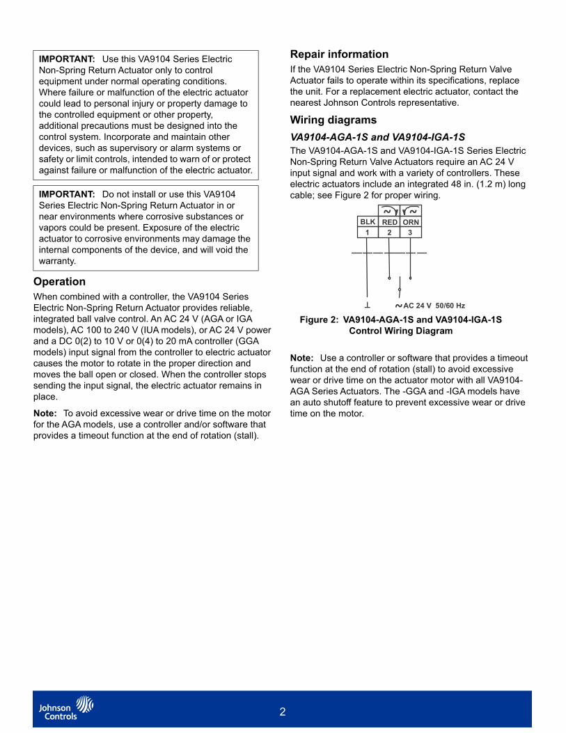
VA9104-AGA-1S and VA9104-IGA-1SThe VA9104-AGA-1S and VA9104-IGA-1S Series Electric Non-Spring Return Valve Actuators require an AC 24 V input signal and work with a variety of controllers. These electric actuators include an integrated 48 in. (1.2 m) long cable; see Figure 2 for proper wiring.
Note: Use a controller or software that provides a timeout function at the end of rotation (stall) to avoid excessive wear or drive time on the actuator motor with all VA9104-AGA Series Actuators. The -GGA and -IGA models have an auto shutoff feature to prevent excessive wear or drive time on the motor.
IMPORTANT: Use this VA9104 Series Electric Non-Spring Return Actuator only to control equipment under normal operating conditions. Where failure or malfunction of the electric actuator could lead to personal injury or property damage to the controlled equipment or other property, additional precautions must be designed into the control system. Incorporate and maintain other devices, such as supervisory or alarm systems or safety or limit controls, intended to warn of or protect against failure or malfunction of the electric actuator.
IMPORTANT: Do not install or use this VA9104 Series Electric Non-Spring Return Actuator in or near environments where corrosive substances or vapors could be present. Exposure of the electric actuator to corrosive environments may damage the internal components of the device, and will void the warranty.
Figure 2: VA9104-AGA-1S and VA9104-IGA-1S Control Wiring Diagram
RED ORNBLK
1 2 3
~AC 24 V 50/60 Hz
~ ~
2

VA9104-AGA-3S and VA9104-IGA-3SThe VA9104-AGA-3S and VA9104-IGA-3S Series Electric Non-Spring Return Valve Actuators require an AC 24 V input signal and work with a variety of controllers. These electric actuators include M3 screw terminals that require a slotted screwdriver; see Figure 3 and Figure 4 for proper wiring.
VA9104-IUA-1SThe VA9104-IUA-1S Series Electric Non-Spring Return Valve Actuators require an 85 to 265 V AC input signal and work with a variety of controllers. These actuators include an integrated 48 in. (1.2 m) long cable; see Figure 5 and Figure 6 for proper wiring.
Figure 3: VA9104-AGA-3S control wiring diagram
Figure 4: VA9104-IGA-3S control wiring diagram
Figure 5: VA9104-IUA-1S control wiring diagram
BLK ORNWHT
1 2 3
~ ~
AC 100...240 V 50/60 Hz
Figure 6: VA9104-IUA-1S on/off control wiring diagram
WHT BLK ORN
AC 100...240 V
S1 ONOFF
S1
50/60 Hz
DA
RA
3
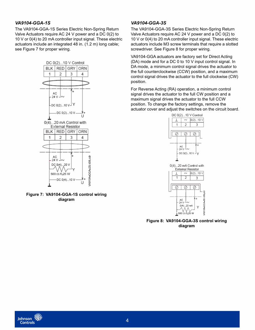
VA9104-GGA-1SThe VA9104-GGA-1S Series Electric Non-Spring Return Valve Actuators require AC 24 V power and a DC 0(2) to 10 V or 0(4) to 20 mA controller input signal. These electric actuators include an integrated 48 in. (1.2 m) long cable; see Figure 7 for proper wiring.
VA9104-GGA-3SThe VA9104-GGA-3S Series Electric Non-Spring Return Valve Actuators require AC 24 V power and a DC 0(2) to 10 V or 0(4) to 20 mA controller input signal. These electric actuators include M3 screw terminals that require a slotted screwdriver. See Figure 8 for proper wiring.
VA9104-GGA actuators are factory set for Direct Acting (DA) mode and for a DC 0 to 10 V input control signal. In DA mode, a minimum control signal drives the actuator to the full counterclockwise (CCW) position, and a maximum control signal drives the actuator to the full clockwise (CW) position.
For Reverse Acting (RA) operation, a minimum control signal drives the actuator to the full CW position and a maximum signal drives the actuator to the full CCW position. To change the factory settings, remove the actuator cover and adjust the switches on the circuit board.
Figure 7: VA9104-GGA-1S control wiring diagram
Figure 8: VA9104-GGA-3S control wiring diagram
4

The VA9104-GGA features 24 VAC override on the signal input allowing for application logic based fail position. Various wiring diagrams are provided to suit your application (Figure 9).
1 2 3 4
~
Y
COM
U
BLK RED GRY ORN
+
+
Override to MIN position
AC24 V
DC 0(2)...10 V
DC 0(2)...10 V
A
A Open = MIN PositionA Closed = Normal Operation
1 2 3 4
~
Y
COM
U
BLK RED GRY ORN
+
+
Override to MAX position
AC24 V
DC 0(2)...10 V
DC 0(2)...10 V
C
B Closed = MAX PositionC Closed = Normal Operation
B
1 2 3 4
~
COMU
BLK RED GRY ORN
+
+
Override toMIN, MID, MAX positions0(4)...20 mA Control with
External Resistor
AC24 V
A
0(4)...20 mA
500 / 0.25 W
B
C
1 2 3 4
~
COMU
BLK RED GRY ORN
+
+
Override toMIN, MID, MAX positions
0(2)...10 V Control
AC24 V
A
B
CDC 0(2)...10 V
Y
FUNCTION A B C
0% ( MIN )
50% ( MID )
100% ( MAX )
NORMAL
FUNCTION A B C
0% ( MIN )
50% ( MID )
100% ( MAX )
NORMAL
Y
Ω
FIG:VA9104GGx2(Z)_wir
Figure 9: VA9104-GGA control wiring diagram(overrides)
5

Ordering information
Table 2: Selection chart
Code number Rotation time For 90°
Power requirement
Power consumption Input signal Position feedback
Electrical connection
Po
we
r O
n
– R
un
nin
g (
Sec
on
ds)
24
VA
C +
25
%/-
20
% a
t 50
/60
Hz
85
to
26
5 V
at
50
/60
Hz
Am
per
age:
Ru
nn
ing
VA
Rat
ing
, Tr
ansf
orm
er S
izin
g
Flo
atin
g P
oin
t W
ith
ou
t T
imeo
ut
On
/Off
an
d F
loat
ing
Po
int
Wit
h T
ime
ou
t
0 (
2)
to 1
0 V
DC
0 (
4)
to 2
0 m
A (
wit
h 5
00
oh
m R
es
isto
r)
0(2
) to
10
VD
C
1.2
m (
48
in.)
Po
lyvi
ny
l Ch
lori
de
(P
VC
) c
ab
le w
ith
0.
75 m
m2
con
du
cto
rs (
19 A
WG
) an
d
6mm
(.2
5in
.) f
err
ule
en
ds
48 in
. (1
.2 m
) w
ith
18
AW
G (
1.0
2 m
m)
con
du
cto
rs a
nd
co
nn
ecto
r fo
r 3/
8 in
. (9
.5 m
m)
flex
ible
met
al c
on
du
it
M3
Sc
rew
Ter
min
als
(R
eq
uir
e a
S
lott
ed
Scr
ewd
rive
r)
VA9104-AGA-1S 60 s at 60 Hz72 s at 50 Hz
X 2.3 X X
VA9104-AGA-3S 60 s at 60 Hz72 s at 50 Hz
X 2.3 X X
VA9104-GGA-1S 60 s at 60 Hz72 s at 50 Hz
X 2.9 X X X
VA9104-GGA-3S 60 s at 60 Hz72 s at 50 Hz
X 2.9 X X
VA9104-IGA-1S 60 s at 60 Hz72 s at 50 Hz
X 3.0 X X
VA9104-IGA-3S 60 s at 60 Hz72 s at 50 Hz
X 3.0 X X
VA9104-IUA-1S 60 s at 60 Hz60 s at 50 Hz
X 0.07 A 7.5 X X
Table 3: Accessories (order separately)
Code number Description
M9000-342 Weather Shield Kit for VG1000 Series Ball application of VA9104, VA9203, VA9208, and VA9308/9310 Series Electric Actuators (quantity 1)
M9000-551 Mounting Hardware Replacement Kit (quantity 1)
M9000-561 Thermal Barrier Kit. Extends the VA9104, VA9203, VA9208, and VA9308/9310 Series Electric Actuators applications to include low pressure steam (quantity 1).
M9000-700 Universal Ball Valve Linkage Kit (quantity 1)
6

Technical specifications
VA9104 Series Electric Non-Spring Return Valve Actuators (Part 1 of 2 )
Power requirements VA9104-xxx-xS AC 24 V +25%/-20% at 50/60 Hz, 2.3 VA (-AGA), 2.9 VA (-GGA), 3.0 VA (-IGA) Supply, Class 2 or Safety Extra-Low Voltage (SELV)
VA9104-IUA-xS AC 100 to 240 V (-15%/+10%) at 50/60 Hz, 0.07 A running, and 7.5 VA supply
Control type VA9104-AGA-xS Floating control without timeout
VA9104-GGA-xS Proportional control
VA9104-IxA-xS Floating or on/off control with timeout
Control signal VA9104-AGA-xS AC 24 V +25%/-20% at 50/60 Hz, Class 2 or SELV without timeout
VA9104-GGA-xS DC 0 (2) to 10 V or 0 (4) to 20 mA with field-furnished 500 ohm resistor
VA9104-IGA-xS AC 24 V +25%/-20% at 50/60 Hz, Class 2 or SELV with timeout
VA9104-IUA-xS AC 100 to 240V -15%/+10% at 50/60 Hz, and 7.5 VA supply
Control input impedance VA9104-GGA-xS Voltage input: 200,000 ohmCurrent input: 500 ohm with field-furnished 500 ohm resistor
Running torque 35 lbin (4 Nm)
Travel time VA9104-xGA-xS 60 seconds at 60 Hz (72 Seconds at 50 Hz) for 90° of rotation
VA9104-IUA-1S 60 seconds for 90° of rotation
Rotation range 93° ±3°, CW or CCW
Cycles 100,000 full stroke cycles; 2,500,000 repositions at rated running torque
Audible noise rating 35 dBA at 39-13/32 in. (1 m) maximum
Electrical connections VA9104-xxA-1S 1.2 m (48 in.) Polyvinyl Chloride (PVC) cable with 0.75 mm2 conductors(19 AWG) and 6 mm (.25 in.) ferrule ends
VA9104-xGA-3S M3 screw terminals (requires a slotted screwdriver)
VA9104-IUA-1S 48 in. (1.2 m) with 18 AWG (1.02 mm) conductors and connector for 3/8 in. (9.5 mm) flexible metal conduit.
Enclosure VA9104-xxA-1S NEMA 2, IP42
VA9104-xGA-3S NEMA 1, IP40
Ambient conditions Operating -4 to 140°F (-20 to 60°C); 90% RH maximum, noncondensing
Storage -40 to 185°F (-40 to 85°C); 90% RH maximum, noncondensing
Fluid temperature limits(actuator and valve assembly)
VG12x1 and VG18x1 Series
23 to 203°F (-5 to 95°C)
VG12x5 and VG18x5 Series
-22 to 212°F (-30 to 100°C)
VG12x5 and VG18x5 Series with M9000-561 Thermal Barrier installed
-22 to 284°F (-30 to 140°C) water; 15 psig (103 kPa) at 250°F (121°C) saturated steam
7

Compliance United States UL Listed, CCN XAPX, File 27734Plenum rated, UL2043, suitable for use in other environmental spaces (plenums) in accordance with section 300.22.(c) of the National Electrical Code
Canada cUL Listed, CCN XAPX7, File 27734Plenum Rated Per CSA 22.2 No. 236/UL 1995, Heating and Cooling Equipment
Europe Johnson Controls declares that this product is in compliance with the essential requirements and other relevant provisions of the EMC Directive 2004/108/EC and the Low Voltage Directive 2006/95/EC.
Australia and New Zealand
RCM Mark, Australia/NZ Emissions Compliant
Shipping weight 1.25 lb (0.55 kg)
Software license Any software (including firmware) included in or with this product is licensed, not sold. Any Johnson Controls software included in or with this product is subject to the terms of the Johnson Controls End User License Agreement available at https://www.johnsoncontrols.com/buildings/legal/digital/generaleula Any third party software (including open source software, if any) included in or with this product is subject to the terms of its respective license.By using any of the foregoing software, you are also agreeing to be bound to the terms of such licenses.
European Single Point of Contact: NA/SA Single Point of Contact: APAC Single Point of Contact:
JOHNSON CONTROLSWESTENDHOF 345143 ESSENGERMANY
JOHNSON CONTROLS507 E MICHIGAN STMILWAUKEE WI 53202USA
JOHNSON CONTROLSC/O CONTROLS PRODUCT MANAGEMENTNO. 22 BLOCK D NEW DISTRICTWUXI JIANGSU PROVINCE 214142CHINA
VA9104 Series Electric Non-Spring Return Valve Actuators (Part 2 of 2 )
The performance specifications are nominal and conform to acceptable industry standards. For application at conditions beyond these specifications, consult the local Johnson Controls office. Johnson Controls shall not be liable for damages resulting from misapplication or misuse of its products.
Johnson Controls® is a registered trademark of Johnson Controls.All other marks herein are the marks of their respective owners. © 2021 Johnson Controls
Building Technologies & Solutions507 E. Michigan Street, Milwaukee, WI 5320
8
www.johnsoncontrols.com
Top Related