


Languages
Pages
Legal


cui.com
date 09/12/2018
page 1 of 10
SERIES: V78E-500-SMT DESCRIPTION: NON-ISOLATED DC SWITCHING REGULATOR
FEATURES• 500 mA of output current• efficiency up to 95%• SMT package• industrial operating temp -40~+85°C• designed to meet IEC/EN 62368-1• industry standard footprint• no load input current of 0.2 mA• output short circuit protection on output
MODEL input voltage1
output voltage
outputcurrent
output power
ripple & noise2
efficiency3
typ(Vdc)
range(Vdc) (Vdc)
max(mA)
max(W)
max(mVp-p)
typ(%)
V78E01-500-SMT 12 4.75~28 1.5 500 0.75 50 76
V78E02-500-SMT 12 4.75~32 2.5 500 1.25 50 81
V78E03-500-SMT 24 4.75~36 3.3 500 1.65 50 86
V78E05-500-SMT 24 6.5~36 5 500 2.5 50 90
V78E06-500-SMT 24 8~36 6.5 500 3.25 50 92
V78E09-500-SMT 24 12~36 9 500 4.5 50 93
V78E12-500-SMT 24 15~36 12 500 6 50 94
V78E15-500-SMT 24 19~36 15 500 7.5 50 95Notes: 1. For input voltages higher than 30 Vdc, a 22 µF / 50 V input capacitor is required. 2. Tested at nominal input, 20 MHz bandwidth, with 10 µF electrolytic and 1 µF ceramic capacitor on the output. For 1.5~3.3 Vdc output models, tested at 20~100% load. For all other models, tested at 10~100% load. At loads below 20% for 1.5~3.3 Vdc output models, the max ripple and noise will be 100 mVp-p. At loads below 10% for all other models, the max ripple and noise will be 150 mVp-p. 3. Measured at min Vin, full load. 4. All specifications are measured at Ta=25°C, humidity < 75%, nominal input voltage, and rated output load unless otherwise specified.
PART NUMBER KEY
Base Number
V78E XX-500-SMT-TR
Output Voltage Output Current
For more information, please visit the product page.
cui.com
date 09/12/2018 page 2 of 10CUI Inc SERIES: V78E-500-SMT DESCRIPTION: NON-ISOLATED DC SWITCHING REGULATOR
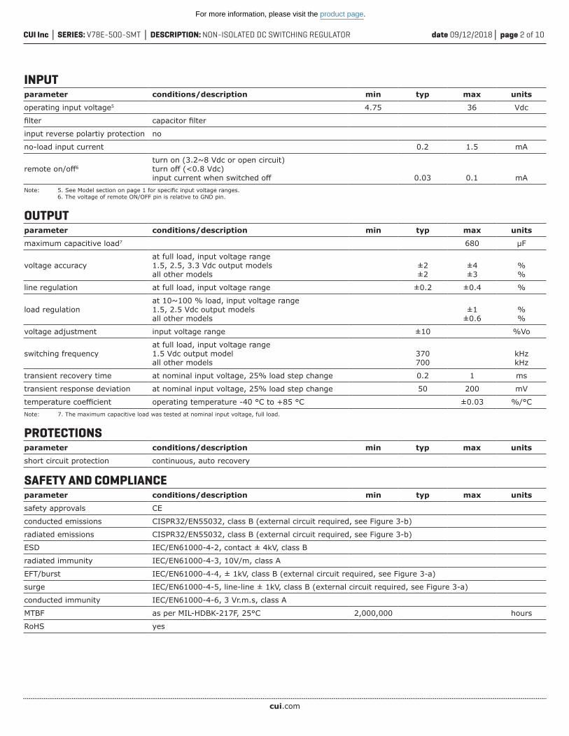
INPUTparameter conditions/description min typ max units
operating input voltage5 4.75 36 Vdc
filter capacitor filter
input reverse polartiy protection no
no-load input current 0.2 1.5 mA
remote on/off6turn on (3.2~8 Vdc or open circuit)turn off (<0.8 Vdc)input current when switched off 0.03 0.1 mA
Note: 5. See Model section on page 1 for specific input voltage ranges. 6. The voltage of remote ON/OFF pin is relative to GND pin.
OUTPUTparameter conditions/description min typ max units
maximum capacitive load7 680 μF
voltage accuracyat full load, input voltage range 1.5, 2.5, 3.3 Vdc output modelsall other models
±2±2
±4±3
%%
line regulation at full load, input voltage range ±0.2 ±0.4 %
load regulationat 10~100 % load, input voltage range 1.5, 2.5 Vdc output modelsall other models
±1±0.6
%%
voltage adjustment input voltage range ±10 %Vo
switching frequencyat full load, input voltage range1.5 Vdc output modelall other models
370700
kHzkHz
transient recovery time at nominal input voltage, 25% load step change 0.2 1 ms
transient response deviation at nominal input voltage, 25% load step change 50 200 mV
temperature coefficient operating temperature -40 °C to +85 °C ±0.03 %/°CNote: 7. The maximum capacitive load was tested at nominal input voltage, full load.
PROTECTIONS parameter conditions/description min typ max units
short circuit protection continuous, auto recovery
SAFETY AND COMPLIANCEparameter conditions/description min typ max units
safety approvals CE
conducted emissions CISPR32/EN55032, class B (external circuit required, see Figure 3-b)
radiated emissions CISPR32/EN55032, class B (external circuit required, see Figure 3-b)
ESD IEC/EN61000-4-2, contact ± 4kV, class B
radiated immunity IEC/EN61000-4-3, 10V/m, class A
EFT/burst IEC/EN61000-4-4, ± 1kV, class B (external circuit required, see Figure 3-a)
surge IEC/EN61000-4-5, line-line ± 1kV, class B (external circuit required, see Figure 3-a)
conducted immunity IEC/EN61000-4-6, 3 Vr.m.s, class A
MTBF as per MIL-HDBK-217F, 25°C 2,000,000 hours
RoHS yes
For more information, please visit the product page.

cui.com
date 09/12/2018 page 3 of 10CUI Inc SERIES: V78E-500-SMT DESCRIPTION: NON-ISOLATED DC SWITCHING REGULATOR
Time (sec)
Tem
pera
ture
(°C
)Peak Temp 245°C (Max)
60 Sec Max(>217°C)
250245
217200
150
100
50
0
ENVIRONMENTALparameter conditions/description min typ max units
operating temperature see derating curve -40 85 °C
storage temperature -55 125 °C
storage humidity non-condensing 95 %
SOLDERABILITYparameter conditions/description min typ max units
reflow soldering see reflow profile, refer to IPC/JEDEC J-STD-020D.1 245 °C
MECHANICALparameter conditions/description min typ max units
dimensions 15.24 x 8.50 x 8.25 [0.60 x 0.335 x 0.325 inch] mm
case material black flame-retardant and heat resistant plastic (UL94V-0)
weight 1.5 g
MECHANICAL DRAWINGunits: mm [inch]tolerance: ±0.50[±0.020]pin section tolerance: ±0.10[±0.004]
PIN CONNECTIONS
PIN FUNCTION
1 +VIN
2 +VIN
3 GND
4 +VOUT
5 +VOUT
6 V adj
7 GND
10 remote on/off
Recommended PCB Layout Top View
For more information, please visit the product page.

cui.com
date 09/12/2018 page 4 of 10CUI Inc SERIES: V78E-500-SMT DESCRIPTION: NON-ISOLATED DC SWITCHING REGULATOR
DERATING CURVE
Ambient Temperature (°C)
Load
(%
)
-40
60
80
100
40
20
0 40 85
120
12071 0
EFFICIENCY CURVES
4.75 7 10 12 15 18 20 22 25 28
85
80
Effic
ienc
y (%
) 75
70
Input Voltage (Vdc)
90
65
60
55
50
45
40 5 10 20 30 40 50 60 70 80 90 100
90
80
70
6050
Effic
ienc
y (%
)
Output Current (%)
100
40
30
0
1020
V78E01-500-SMT Efficiency CurveEfficiency vs. Input Voltage
(at full load)
V78E01-500-SMT Efficiency CurveEfficiency vs. Load Current
(at Vin nominal)
4.75 8 11 14 17 20 23 26 29 32
85
80
Effic
ienc
y (%
) 75
70
Input Voltage (Vdc)
90
65
60
55
50
45
40
V78E02-500-SMT Efficiency CurveEfficiency vs. Input Voltage
(at full load)
V78E02-500-SMT Efficiency CurveEfficiency vs. Load Current
(at Vin nominal)
5 10 20 30 40 50 60 70 80 90 100
90
80
70
6050
Effic
ienc
y (%
)
Output Current (%)
100
40
30
0
1020
Temperature Derating Curve(Natural Convection)
For more information, please visit the product page.

cui.com
date 09/12/2018 page 5 of 10CUI Inc SERIES: V78E-500-SMT DESCRIPTION: NON-ISOLATED DC SWITCHING REGULATOR
4.75 8 12 16 20 24 28 31 34 36
95
90
Effic
ienc
y (%
) 85
80
Input Voltage (Vdc)
100
75
70
65
60
55
50 5 10 20 30 40 50 60 70 80 90 100
90
80
70
6050
Effic
ienc
y (%
)
Output Current (%)
100
40
30
0
1020
V78E03-500-SMT Efficiency CurveEfficiency vs. Input Voltage
(at full load)
V78E03-500-SMT Efficiency CurveEfficiency vs. Load Current
(at Vin nominal)
EFFICIENCY CURVES (CONTINUED)
6.5 10 13 16 20 24 27 30 33 36
95
90
Effic
ienc
y (%
) 85
80
Input Voltage (Vdc)
100
75
70
65
60
55
50 5 10 20 30 40 50 60 70 80 90
90
80
Effic
ienc
y (%
) 70
60
100
50
40
30
20
10
0
Output Current (%)
V78E05-500-SMT Efficiency CurveEfficiency vs. Input Voltage
(at full load)
V78E05-500-SMT Efficiency CurveEfficiency vs. Load Current
(at Vin nominal)
8 11 14 17 20 24 27 30 33 36
95
90
Effic
ienc
y (%
) 85
80
Input Voltage (Vdc)
100
75
70
65
60
55
50 5 10 20 30 40 50 60 70 80 90 100
90
80
70
6050
Effic
ienc
y (%
)
Output Current (%)
100
40
30
0
1020
V78E06-500-SMT Efficiency CurveEfficiency vs. Input Voltage
(at full load)
V78E06-500-SMT Efficiency CurveEfficiency vs. Load Current
(at Vin nominal)
For more information, please visit the product page.

cui.com
date 09/12/2018 page 6 of 10CUI Inc SERIES: V78E-500-SMT DESCRIPTION: NON-ISOLATED DC SWITCHING REGULATOR
12 15 18 21 24 27 30 33 36
95
90
Effic
ienc
y (%
) 85
80
Input Voltage (Vdc)
100
75
70
65
60
55
50 5 10 20 30 40 50 60 70 80 90 100
90
80
70
6050
Effic
ienc
y (%
)
Output Current (%)
100
40
30
0
1020
V78E09-500-SMT Efficiency CurveEfficiency vs. Input Voltage
(at full load)
V78E09-500-SMT Efficiency CurveEfficiency vs. Load Current
(at Vin nominal)
EFFICIENCY CURVES (CONTINUED)
15 18 20 22 24 27 30 33 36
95
90
Effic
ienc
y (%
) 85
80
Input Voltage (Vdc)
100
75
70
65
60
55
50 5 10 20 30 40 50 60 70 80 90 100
90
80
70
6050
Effic
ienc
y (%
)
Output Current (%)
100
40
30
0
1020
V78E12-500-SMT Efficiency CurveEfficiency vs. Input Voltage
(at full load)
V78E12-500-SMT Efficiency CurveEfficiency vs. Load Current
(at Vin nominal)
19 21 23 25 27 29 31 33 35 36
95
90
Effic
ienc
y (%
) 85
80
Input Voltage (Vdc)
100
75
70
65
60
55
50 5 10 20 30 40 50 60 70 80 90
90
80
70
6050
Effic
ienc
y (%
)
Output Current (%)
100
40
30
0
1020
V78E15-500-SMT Efficiency CurveEfficiency vs. Input Voltage
(at full load)
V78E15-500-SMT Efficiency CurveEfficiency vs. Load Current
(at Vin nominal)
For more information, please visit the product page.

cui.com
date 09/12/2018 page 7 of 10CUI Inc SERIES: V78E-500-SMT DESCRIPTION: NON-ISOLATED DC SWITCHING REGULATOR
Table 1
Model Number C1(ceramic capacitor)
C2(ceramic capacitor)
Ra1/Ra2(Vadj resistance)
V78E01-500-SMT 10 μF/50 V 22 μF/10 V
refer to Vadj resistancecalculation
V78E02-500-SMT 10 μF/50 V 22 μF/10 V
V78E03-500-SMT 10 μF/50 V 22 μF/10 V
V78E05-500-SMT 10 μF/50 V 22 μF/16 V
V78E06-500-SMT 10 μF/50 V 22 μF/16 V
V78E09-500-SMT 10 μF/50 V 22 μF/25 V
V78E12-500-SMT 10 μF/50 V 22 μF/25 V
V78E15-500-SMT 10 μF/50 V 22 μF/25 V
TYPICAL APPLICATION CIRCUIT
Application CircuitFigure 1
EMC RECOMMENDED CIRCUIT
Table 2Figure 3
Recommended external circuit components
FUSE choose according to actual input current
MOV S20K30
LDM1 82 µH
C0 680 µF/50 V
C1, C2 refer to table 1
C5 4.7 µF/50 V
LDM2 12 µH
Note: 8. C1 & C2 are required and should be connected as close to the module pins as possible. 9. C1 & C2 can be increased as needed and the use of tantalum or low ESR electrolytic capacitors would be recommended. 10. To reduce the output ripple further, it is recommended to add an “LC” filter at the output (see figure 2) with a 10~47 µH L component.
LC Filter Application CircuitFigure 2
For more information, please visit the product page.

cui.com
date 09/12/2018 page 8 of 10CUI Inc SERIES: V78E-500-SMT DESCRIPTION: NON-ISOLATED DC SWITCHING REGULATOR
1. Output voltage trimming Leave open if not used. Application Circuit for Trim pin Formula for Trim Resistor (part in broken line is the interior of models) Note: Value for R1, R2, R3, and Vref refer to Table 3 Ra1/Ra2: Trim Resistor a: User-defined parameter, no actual meanings Vo': The trim up/down voltage
APPLICATION NOTES
Figure 4
Table 3
Vout(Vdc)
R1(kΩ)
R2(kΩ)
R3(kΩ)
Vref(V)
1.511 7.5 7.5 15 0.75
2.5 27 11.858 51 0.765
3.3 33 9.9 47 0.765
5 75 13.5 75 0.765
6.5 75 10 51 0.765
9 51 4.7 27 0.765
12 75 5.1 27 0.765
15 82 4.423 27 0.765
Note: 11. The 1.5 Vdc output model can only be adjusted up.
0V
R2
R1
R3Vre f
Ra 2
Va dj
Vo’
0V
R2
R1
R3Vref
Ra 1
Va dj
Vo’
Va dj up Va dj down
up: a =Vref
Vo’-Vre f R1R =a 2a R2
R -a2-R3
down: a =Vref
Vo’-Vre fR2R =a 1
a R1
R -a1-R3
For more information, please visit the product page.

cui.com
date 09/12/2018 page 9 of 10CUI Inc SERIES: V78E-500-SMT DESCRIPTION: NON-ISOLATED DC SWITCHING REGULATOR
PACKAGINGunits: mm
Reel Size: Ø330 mmReel QTY: 300 pcs per trayCarton Box Size: 400 x 365 x 255 mmCarton Box QTY: 1,800 pcs per carton box
For more information, please visit the product page.
date 09/12/2018 page 10 of 10CUI Inc SERIES: V78E-500-SMT DESCRIPTION: NON-ISOLATED DC SWITCHING REGULATOR
CUI offers a two (2) year limited warranty. Complete warranty information is listed on our website.
CUI reserves the right to make changes to the product at any time without notice. Information provided by CUI is believed to be accurate and reliable. However, no responsibility is assumed by CUI for its use, nor for any infringements of patents or other rights of third parties which may result from its use.
CUI products are not authorized or warranted for use as critical components in equipment that requires an extremely high level of reliability. A critical component is any component of a life support device or system whose failure to perform can be reasonably expected to cause the failure of the life support device or system, or to affect its safety or effectiveness.
Headquarters20050 SW 112th Ave.Tualatin, OR 97062800.275.4899
rev. description date
1.0 initial release 09/12/2018The revision history provided is for informational purposes only and is believed to be accurate.
REVISION HISTORY
For more information, please visit the product page.
Top Related