


Languages
Pages
Legal

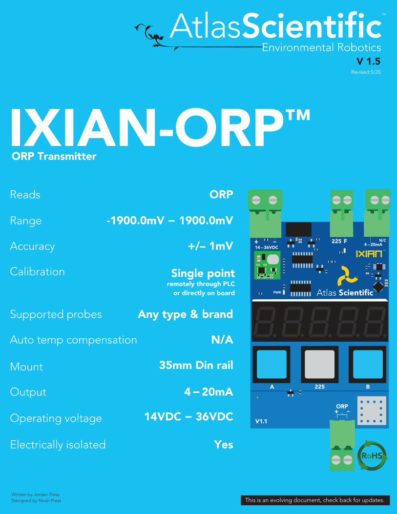
IXIAN-ORPtradeORP Transmitter
Range -19000mV minus 19000mV
+ndash 1mVAccuracy
Any type amp brandSupported probes
Single pointremotely through PLC
or directly on board
Calibration
Reads ORP
V11
225 BA
14VDC minus 36VDCOperating voltage
35mm Din railMount
4 minus 20mAOutput
NAAuto temp compensation
YesElectrically isolated
V 15Revised 520
This is an evolving document check back for updatesWritten by Jordan PressDesigned by Noah Press
Table of contentsTransmitter dimensionsWiring diagramOperating principleMounting
Datasheet change log
3457
21
11
12
1314
151516171819
20
Power connectionORP connection4 ndash 20mA connection
8910
4 ndash 20mA ORP transmissionReading 4 ndash 20mA outputwith a multimeter
PLC calibration nodeFault detect line
Calibration theoryOn-board calibrationPLC calibration4 ndash 20mA calibration4 ndash 20mA High4 ndash 20mA Low
Factory reset
2 Copyright copy Atlas Scientific LLC
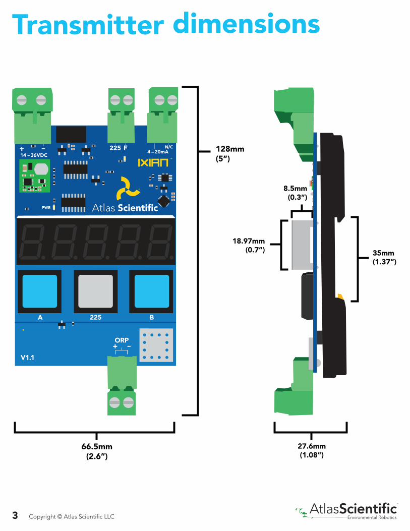
Transmitter dimensions
128mm(5rdquo)
1897mm(07rdquo)
85mm(03rdquo)
35mm(137rdquo)
276mm(108rdquo)
665mm(26rdquo)
V11
225 BA
3 Copyright copy Atlas Scientific LLC
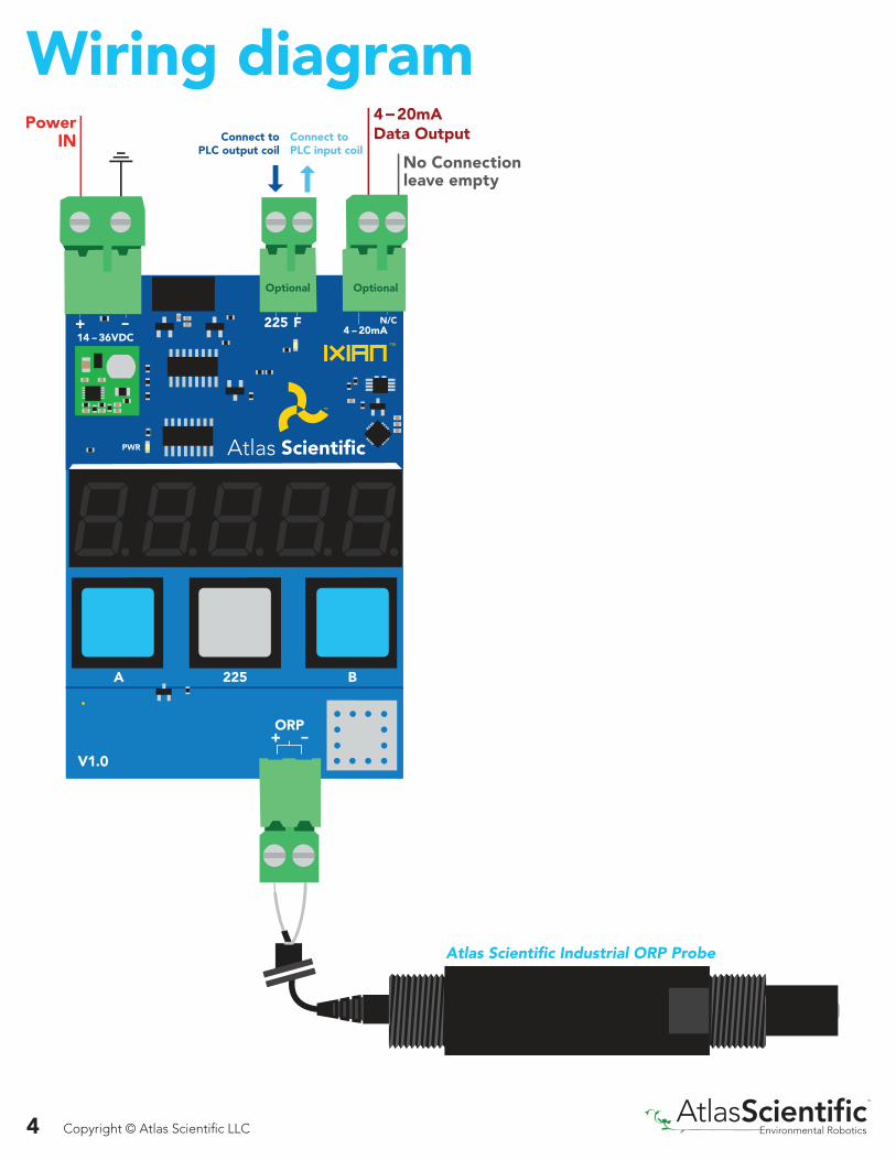
Wiring diagram
V10
225 BA
Connect toPLC output coil
Connect to PLC input coil
Atlas Scientific Industrial ORP Probe
4 Copyright copy Atlas Scientific LLC
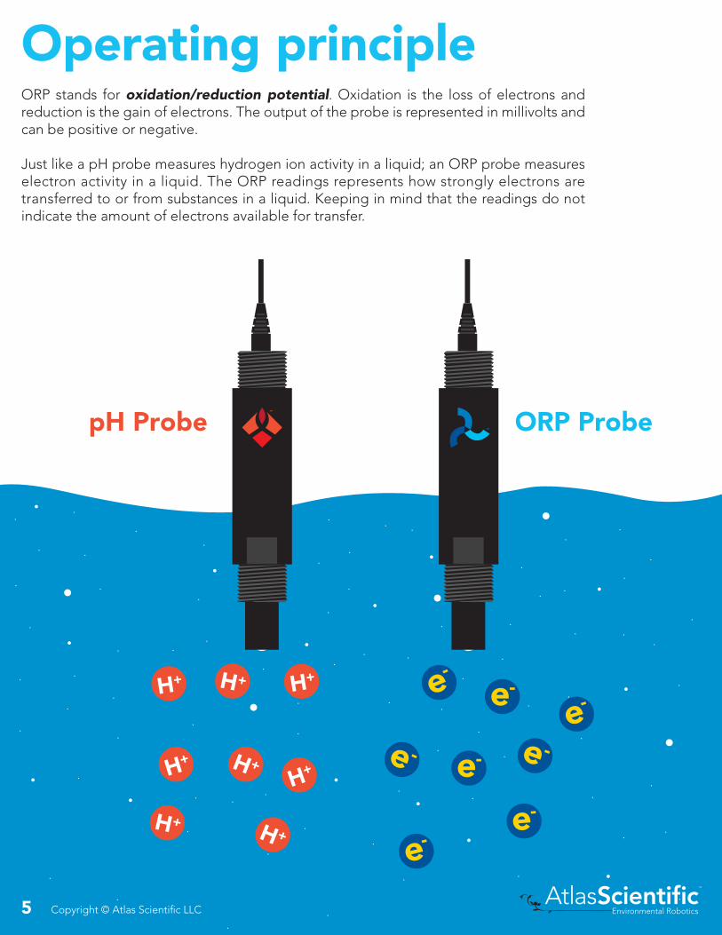
Operating principleORP stands for oxidationreduction potential Oxidation is the loss of electrons and reduction is the gain of electrons The output of the probe is represented in millivolts and can be positive or negative
Just like a pH probe measures hydrogen ion activity in a liquid an ORP probe measures electron activity in a liquid The ORP readings represents how strongly electrons are transferred to or from substances in a liquid Keeping in mind that the readings do not indicate the amount of electrons available for transfer
pH Probe ORP Probe
5 Copyright copy Atlas Scientific LLC
Add just a drop of bleach (which is an oxidizing agent)
6069Reading A
6053Reading B
A B
-2346Reading A
242Reading B
A B
Tap water Tap water
The water is unreactive and has only trace amounts of electron movement These readings are equivalent to the readings you see with an unconnected multimeter
Junction
Reference wire
Silver chloride
Silver wire
KCL reference solution
An ORP probe has a platinum tip that is connected to a silver wire surrounded by silver chloride That silver wire is then connected to a KCL reference solution Because platinum is an unreactive metal it can ldquosilently observerdquo the electron activity of the liquid without becoming apart of whatever reaction is occurring in the liquid
When reading the ORP of a liquid that has very few electrons available for transfer ORP readings can appear to be inconsistent
6 Copyright copy Atlas Scientific LLC
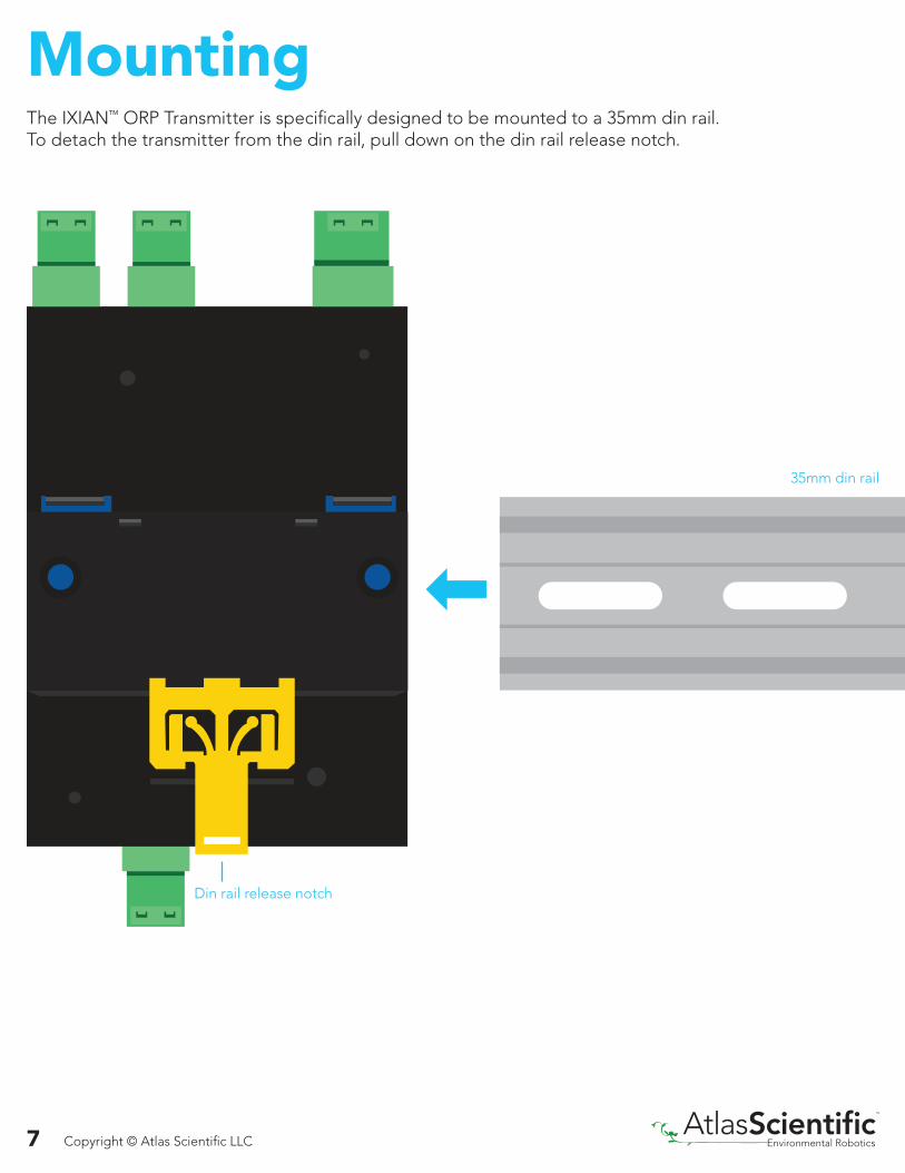
MountingThe IXIANtrade ORP Transmitter is specifically designed to be mounted to a 35mm din railTo detach the transmitter from the din rail pull down on the din rail release notch
35mm din rail
Din rail release notch
7 Copyright copy Atlas Scientific LLC
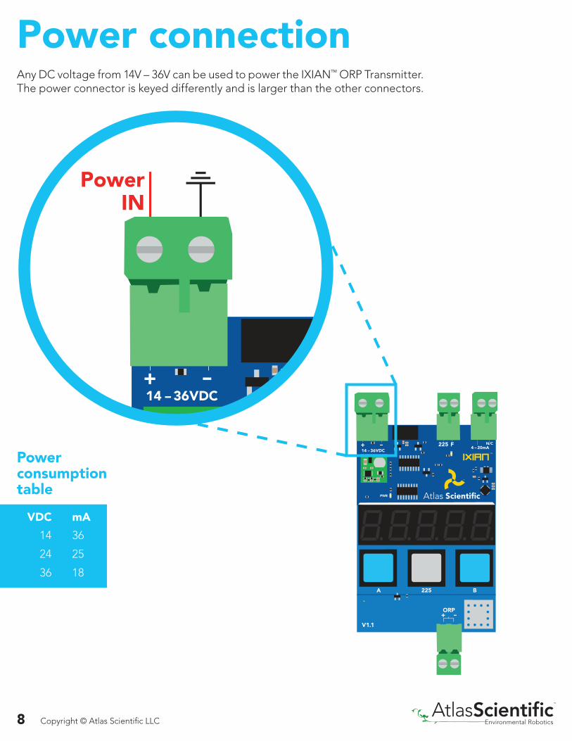
Power connection Any DC voltage from 14V ndash 36V can be used to power the IXIANtrade ORP TransmitterThe power connector is keyed differently and is larger than the other connectors
V11
225 BA
Powerconsumptiontable
mA
36
25
18
VDC
14
24
36
8 Copyright copy Atlas Scientific LLC
ORP connection
Connecting the ORP probe in reverse order will not damage the probe however the readings will be incorrect
Any off the shelf two wire ORP probe can be used with the IXIANtrade ORP Transmitter
225 B V11
225 BA
9 Copyright copy Atlas Scientific LLC
4 ndash 20mA connection
V11
225 BA
Connecting the 4 ndash 20mA data output to your PLC allows the IXIANtrade ORP Transmitter to communicate with your PLC
Connecting the 4 ndash 20mA data output to your PLC is purely optional Leaving it disconnected will have no effect on the IXIANtrade ORP Transmitterrsquos operation
10 Copyright copy Atlas Scientific LLC
4 ndash 20mA ORP transmissionThe ORP value that is visible on the seven segment LED screen is also simultaneously transmitted through the 4 ndash 20mA data output
225
V11
225 BA
Connecting the 4 ndash 20mA data output to your PLC is purely optional Leaving it disconnected will have no effect on the IXIANtrade ORP Transmitterrsquos operation
ORP to 4 ndash 20mA equation
ORP-1900-500-22502255001900
49891105121295141020
mA 10 BIT = 37112 BIT = 09216 BIT = 005
PLC ADC Resolution
Advanced4 ndash 20mA max load resistance
R = the total resistive load on the lineV = the voltage powering the transmitter
11 Copyright copy Atlas Scientific LLC
Reading 4 ndash 20mA output with a multimeterTo debug the IXIANtrade ORP Transmitter output first connect it to a multimeter as shown (make sure the multimeter is set to ldquomArdquo) Once properly connected set the IXIANtrade ORP Transmitter to calibrate to 225 Compare the reading on the multimeter to the chart below
ORP
225 1295
mA
mA
mA1295
V11
225 BA
12 Copyright copy Atlas Scientific LLC
Using the input connection marked ldquo225rdquo itrsquos possible to use a PLC to fully calibrate the IXIANtrade ORP Transmitter This is particularly beneficial when using a PLC touch screen
Sending an output signal from the PLC to the ORP Transmitters 225 input connection will calibrate the device
PLC calibration node
Connecting to the PLC calibration node is purely optional Leaving it disconnected will have no effect on the IXIANtrade ORP Transmitterrsquos operation
V11
225 BA
The voltage used to trigger a calibration event should be the same voltage used to power the IXIANtrade ORP Transmitter
13 Copyright copy Atlas Scientific LLC
Events that will trigger the fault line to go to 0 voltsbull disconnected 4 ndash 20mA outputbull calibration in processbull loss of power
The connection marked ldquoFrdquo is the fault detect line During normal operation the fault detect line will output a voltage equal to the voltage used to power the device If the IXIANtrade ORP Transmitter detects a problem the fault line will drop to 0 volts When a fault is detected the fault LED will turn on
The IXIANtrade ORP Transmitter is powered with 24V the ldquoFrdquo line will output 24V during normal operation
Normal operation
(24V typical)
0 VoltsFault
Example
Fault detect line
Connecting to the fault detect line is purely optional Leaving it disconnected will have no effect on the IXIANtrade ORP Transmitterrsquos operation
V11
225 BA
14 Copyright copy Atlas Scientific LLC
Calibration theoryThe Atlas Scientific IXIANtrade ORP Transmitter has a simple single point calibration protocol Place the probe in the 225mV calibration solution (chemically known as Zobells Solution) Wait for the readings to stabilize then calibrate the transmitter The calibration data is stored in the EEPROM and will be retained even if the Transmitter is powered off
On-board calibrationTo begin the on-board calibration process press and hold the middle gray button marked ldquo225rdquo for 15 seconds to calibrate to an ORP of 225mV
The display will flash 225 after a few seconds the display will then flash donE
15 seconds
V11
225 BA
15 Copyright copy Atlas Scientific LLC
CALTransmitter
( OUT )T1
T1Timer 1
200ms
CALbutton press
Calibrate
225
PLC calibrationUsing the input connection marked ldquo225rdquo itrsquos possible to use a PLC to fully calibrate the IXIANtrade ORP Transmitter Setting the PLCrsquos output to 200ms or more will trigger a calibration event
This is particularly beneficial when using a PLC touch screen
The voltage used to trigger a calibration event should be the same voltage used to power the IXIANtrade ORP Transmitter
A calibration event will only trigger if the corresponding input pin has been held high for 200ms Holding the line for more then 200ms will have no effect
16 Copyright copy Atlas Scientific LLC
4 ndash 20mA calibration
15 secondsV11
225 BA
To ensure that the PLC is receiving the most accurate 4 ndash 20mA signal the current outputfrom the IXIANtrade ORP Transmitter can be adjusted The 4mA signal and the 20mA signalcan both be adjusted independently
To enter 4 ndash 20mA calibration mode press and hold the two blue buttons marked ldquoArdquo and ldquoBrdquo simultaneously for 15 seconds
17 Copyright copy Atlas Scientific LLC
The display will flash 4-20H (the ldquoHrdquo stands for high) The IXIANtrade ORP Transmitter will now output exactly 20mA and your PLC should show an ORP of 1900 Use the gray (up) and blue B (down) buttons to adjust the 20mA output so the ORP moves to 18999 then move it back up so it is just hits 1900 When you have finished making adjustments press the blue A (save) button to confirm
The 20mA offset will be permanently stored in memory
4 ndash 20mA High
V11
225 BA
18999
19000
V11
225 BA
Save
18 Copyright copy Atlas Scientific LLC
4 ndash 20mA Low
V11
225 BA
-18999
-19000
V11
225 BA
Save
The display will flash 4-20L (the ldquoLrdquo stands for low) The IXIANtrade ORP Transmitter will now output exactly 4mA and your PLC should show an ORP of -1900 Use the gray (up) and blue B (down) buttons to adjust the 4mA output so the ORP moves to -18999 then move it back so it is just hits -1900 When you have finished making adjustments press the blue A (save) button to confirm
The 20mA offset will be permanently stored in memory
19 Copyright copy Atlas Scientific LLC
Factory resetThe IXIANtrade ORP Transmitter can be reset to its default settings To issue a factory reset press and hold the gray and blue B buttons for three seconds
Press and hold the gray and blue B buttons again to confirm the factory resetTo cancel a factory reset press the blue A button
The display will flash rEsEt
3 secondsV11
225 BA
Cancel
20 Copyright copy Atlas Scientific LLC
Datasheet change log
Corrected typo on pg 16
Revised enitre datasheet
Datasheet V 11
Datasheet V 10
Added info about calibration data saved to EEPROM on pg 15
Datasheet V 12
Revised math equation on pg 11
Datasheet V 13
Added 4 ndash 20mA max load resistance formula on pg 11
Datasheet V 14
21 Copyright copy Atlas Scientific LLC
Table of contentsTransmitter dimensionsWiring diagramOperating principleMounting
Datasheet change log
3457
21
11
12
1314
151516171819
20
Power connectionORP connection4 ndash 20mA connection
8910
4 ndash 20mA ORP transmissionReading 4 ndash 20mA outputwith a multimeter
PLC calibration nodeFault detect line
Calibration theoryOn-board calibrationPLC calibration4 ndash 20mA calibration4 ndash 20mA High4 ndash 20mA Low
Factory reset
2 Copyright copy Atlas Scientific LLC
Transmitter dimensions
128mm(5rdquo)
1897mm(07rdquo)
85mm(03rdquo)
35mm(137rdquo)
276mm(108rdquo)
665mm(26rdquo)
V11
225 BA
3 Copyright copy Atlas Scientific LLC
Wiring diagram
V10
225 BA
Connect toPLC output coil
Connect to PLC input coil
Atlas Scientific Industrial ORP Probe
4 Copyright copy Atlas Scientific LLC
Operating principleORP stands for oxidationreduction potential Oxidation is the loss of electrons and reduction is the gain of electrons The output of the probe is represented in millivolts and can be positive or negative
Just like a pH probe measures hydrogen ion activity in a liquid an ORP probe measures electron activity in a liquid The ORP readings represents how strongly electrons are transferred to or from substances in a liquid Keeping in mind that the readings do not indicate the amount of electrons available for transfer
pH Probe ORP Probe
5 Copyright copy Atlas Scientific LLC
Add just a drop of bleach (which is an oxidizing agent)
6069Reading A
6053Reading B
A B
-2346Reading A
242Reading B
A B
Tap water Tap water
The water is unreactive and has only trace amounts of electron movement These readings are equivalent to the readings you see with an unconnected multimeter
Junction
Reference wire
Silver chloride
Silver wire
KCL reference solution
An ORP probe has a platinum tip that is connected to a silver wire surrounded by silver chloride That silver wire is then connected to a KCL reference solution Because platinum is an unreactive metal it can ldquosilently observerdquo the electron activity of the liquid without becoming apart of whatever reaction is occurring in the liquid
When reading the ORP of a liquid that has very few electrons available for transfer ORP readings can appear to be inconsistent
6 Copyright copy Atlas Scientific LLC
MountingThe IXIANtrade ORP Transmitter is specifically designed to be mounted to a 35mm din railTo detach the transmitter from the din rail pull down on the din rail release notch
35mm din rail
Din rail release notch
7 Copyright copy Atlas Scientific LLC
Power connection Any DC voltage from 14V ndash 36V can be used to power the IXIANtrade ORP TransmitterThe power connector is keyed differently and is larger than the other connectors
V11
225 BA
Powerconsumptiontable
mA
36
25
18
VDC
14
24
36
8 Copyright copy Atlas Scientific LLC
ORP connection
Connecting the ORP probe in reverse order will not damage the probe however the readings will be incorrect
Any off the shelf two wire ORP probe can be used with the IXIANtrade ORP Transmitter
225 B V11
225 BA
9 Copyright copy Atlas Scientific LLC
4 ndash 20mA connection
V11
225 BA
Connecting the 4 ndash 20mA data output to your PLC allows the IXIANtrade ORP Transmitter to communicate with your PLC
Connecting the 4 ndash 20mA data output to your PLC is purely optional Leaving it disconnected will have no effect on the IXIANtrade ORP Transmitterrsquos operation
10 Copyright copy Atlas Scientific LLC
4 ndash 20mA ORP transmissionThe ORP value that is visible on the seven segment LED screen is also simultaneously transmitted through the 4 ndash 20mA data output
225
V11
225 BA
Connecting the 4 ndash 20mA data output to your PLC is purely optional Leaving it disconnected will have no effect on the IXIANtrade ORP Transmitterrsquos operation
ORP to 4 ndash 20mA equation
ORP-1900-500-22502255001900
49891105121295141020
mA 10 BIT = 37112 BIT = 09216 BIT = 005
PLC ADC Resolution
Advanced4 ndash 20mA max load resistance
R = the total resistive load on the lineV = the voltage powering the transmitter
11 Copyright copy Atlas Scientific LLC
Reading 4 ndash 20mA output with a multimeterTo debug the IXIANtrade ORP Transmitter output first connect it to a multimeter as shown (make sure the multimeter is set to ldquomArdquo) Once properly connected set the IXIANtrade ORP Transmitter to calibrate to 225 Compare the reading on the multimeter to the chart below
ORP
225 1295
mA
mA
mA1295
V11
225 BA
12 Copyright copy Atlas Scientific LLC
Using the input connection marked ldquo225rdquo itrsquos possible to use a PLC to fully calibrate the IXIANtrade ORP Transmitter This is particularly beneficial when using a PLC touch screen
Sending an output signal from the PLC to the ORP Transmitters 225 input connection will calibrate the device
PLC calibration node
Connecting to the PLC calibration node is purely optional Leaving it disconnected will have no effect on the IXIANtrade ORP Transmitterrsquos operation
V11
225 BA
The voltage used to trigger a calibration event should be the same voltage used to power the IXIANtrade ORP Transmitter
13 Copyright copy Atlas Scientific LLC
Events that will trigger the fault line to go to 0 voltsbull disconnected 4 ndash 20mA outputbull calibration in processbull loss of power
The connection marked ldquoFrdquo is the fault detect line During normal operation the fault detect line will output a voltage equal to the voltage used to power the device If the IXIANtrade ORP Transmitter detects a problem the fault line will drop to 0 volts When a fault is detected the fault LED will turn on
The IXIANtrade ORP Transmitter is powered with 24V the ldquoFrdquo line will output 24V during normal operation
Normal operation
(24V typical)
0 VoltsFault
Example
Fault detect line
Connecting to the fault detect line is purely optional Leaving it disconnected will have no effect on the IXIANtrade ORP Transmitterrsquos operation
V11
225 BA
14 Copyright copy Atlas Scientific LLC
Calibration theoryThe Atlas Scientific IXIANtrade ORP Transmitter has a simple single point calibration protocol Place the probe in the 225mV calibration solution (chemically known as Zobells Solution) Wait for the readings to stabilize then calibrate the transmitter The calibration data is stored in the EEPROM and will be retained even if the Transmitter is powered off
On-board calibrationTo begin the on-board calibration process press and hold the middle gray button marked ldquo225rdquo for 15 seconds to calibrate to an ORP of 225mV
The display will flash 225 after a few seconds the display will then flash donE
15 seconds
V11
225 BA
15 Copyright copy Atlas Scientific LLC
CALTransmitter
( OUT )T1
T1Timer 1
200ms
CALbutton press
Calibrate
225
PLC calibrationUsing the input connection marked ldquo225rdquo itrsquos possible to use a PLC to fully calibrate the IXIANtrade ORP Transmitter Setting the PLCrsquos output to 200ms or more will trigger a calibration event
This is particularly beneficial when using a PLC touch screen
The voltage used to trigger a calibration event should be the same voltage used to power the IXIANtrade ORP Transmitter
A calibration event will only trigger if the corresponding input pin has been held high for 200ms Holding the line for more then 200ms will have no effect
16 Copyright copy Atlas Scientific LLC
4 ndash 20mA calibration
15 secondsV11
225 BA
To ensure that the PLC is receiving the most accurate 4 ndash 20mA signal the current outputfrom the IXIANtrade ORP Transmitter can be adjusted The 4mA signal and the 20mA signalcan both be adjusted independently
To enter 4 ndash 20mA calibration mode press and hold the two blue buttons marked ldquoArdquo and ldquoBrdquo simultaneously for 15 seconds
17 Copyright copy Atlas Scientific LLC
The display will flash 4-20H (the ldquoHrdquo stands for high) The IXIANtrade ORP Transmitter will now output exactly 20mA and your PLC should show an ORP of 1900 Use the gray (up) and blue B (down) buttons to adjust the 20mA output so the ORP moves to 18999 then move it back up so it is just hits 1900 When you have finished making adjustments press the blue A (save) button to confirm
The 20mA offset will be permanently stored in memory
4 ndash 20mA High
V11
225 BA
18999
19000
V11
225 BA
Save
18 Copyright copy Atlas Scientific LLC
4 ndash 20mA Low
V11
225 BA
-18999
-19000
V11
225 BA
Save
The display will flash 4-20L (the ldquoLrdquo stands for low) The IXIANtrade ORP Transmitter will now output exactly 4mA and your PLC should show an ORP of -1900 Use the gray (up) and blue B (down) buttons to adjust the 4mA output so the ORP moves to -18999 then move it back so it is just hits -1900 When you have finished making adjustments press the blue A (save) button to confirm
The 20mA offset will be permanently stored in memory
19 Copyright copy Atlas Scientific LLC
Factory resetThe IXIANtrade ORP Transmitter can be reset to its default settings To issue a factory reset press and hold the gray and blue B buttons for three seconds
Press and hold the gray and blue B buttons again to confirm the factory resetTo cancel a factory reset press the blue A button
The display will flash rEsEt
3 secondsV11
225 BA
Cancel
20 Copyright copy Atlas Scientific LLC
Datasheet change log
Corrected typo on pg 16
Revised enitre datasheet
Datasheet V 11
Datasheet V 10
Added info about calibration data saved to EEPROM on pg 15
Datasheet V 12
Revised math equation on pg 11
Datasheet V 13
Added 4 ndash 20mA max load resistance formula on pg 11
Datasheet V 14
21 Copyright copy Atlas Scientific LLC
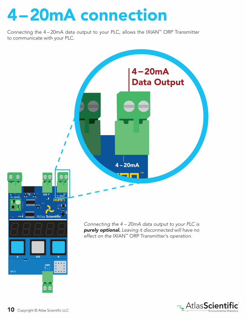
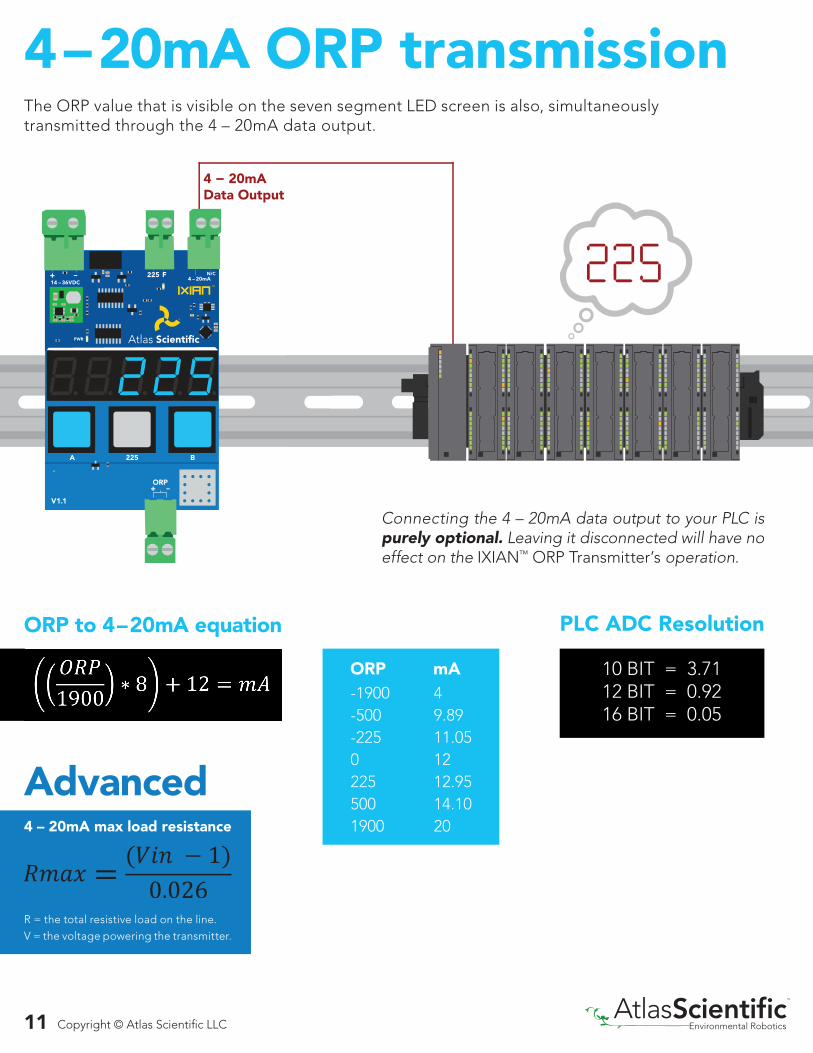
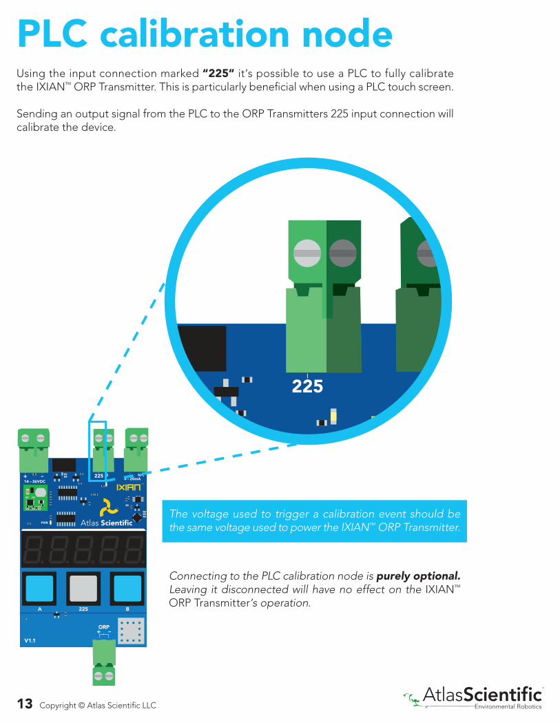
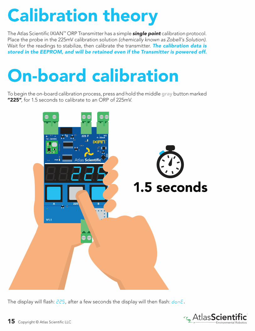
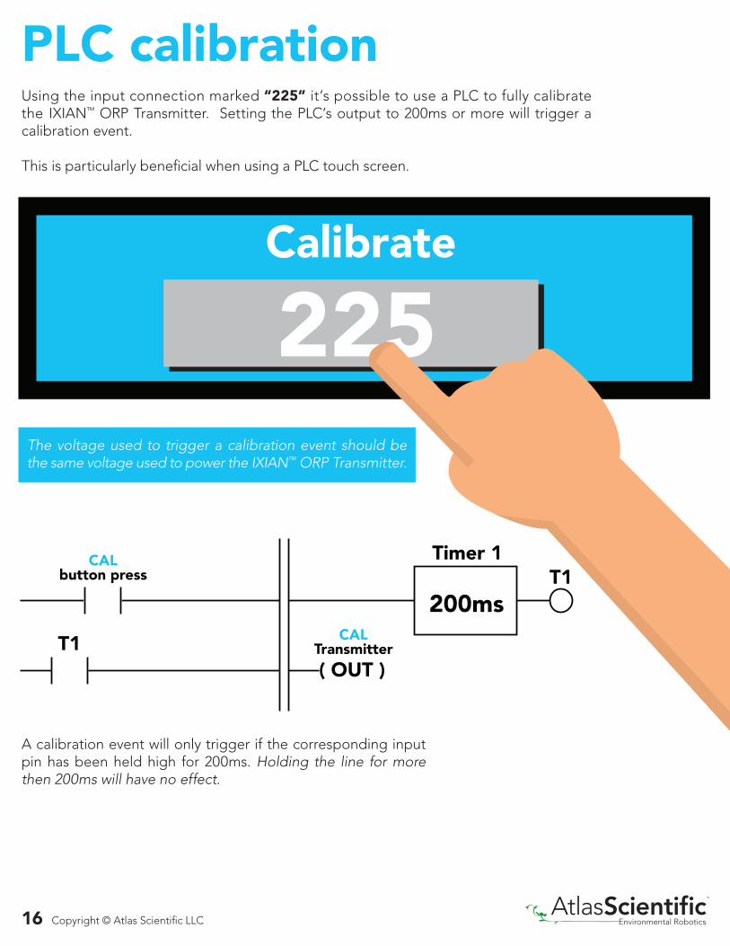
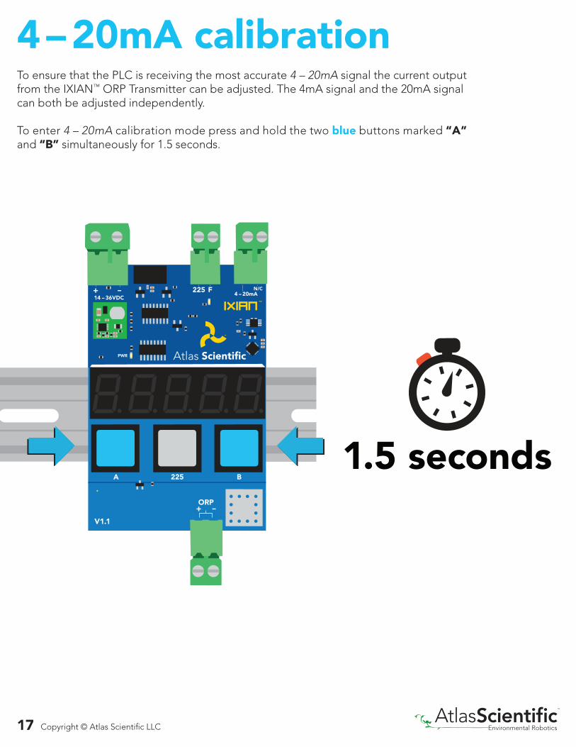
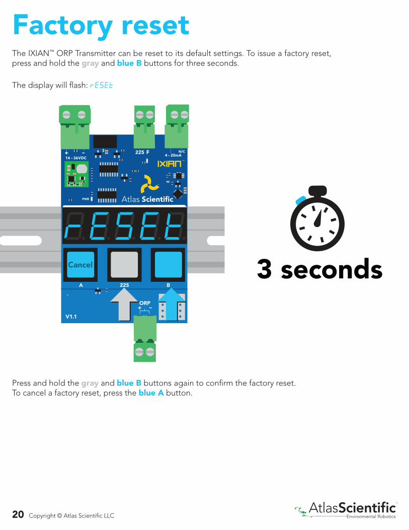
Top Related