


Languages
Pages
Legal

2014 Microchip Technology Inc. DS40001758A
USB to DALI Interface and PCDALI Test Application
User’s Guide

DS40001758A-page 2 2014 Microchip Technology Inc.
Information contained in this publication regarding deviceapplications and the like is provided only for your convenienceand may be superseded by updates. It is your responsibility toensure that your application meets with your specifications.MICROCHIP MAKES NO REPRESENTATIONS ORWARRANTIES OF ANY KIND WHETHER EXPRESS ORIMPLIED, WRITTEN OR ORAL, STATUTORY OROTHERWISE, RELATED TO THE INFORMATION,INCLUDING BUT NOT LIMITED TO ITS CONDITION,QUALITY, PERFORMANCE, MERCHANTABILITY ORFITNESS FOR PURPOSE. Microchip disclaims all liabilityarising from this information and its use. Use of Microchipdevices in life support and/or safety applications is entirely atthe buyer’s risk, and the buyer agrees to defend, indemnify andhold harmless Microchip from any and all damages, claims,suits, or expenses resulting from such use. No licenses areconveyed, implicitly or otherwise, under any Microchipintellectual property rights.
Note the following details of the code protection feature on Microchip devices:• Microchip products meet the specification contained in their particular Microchip Data Sheet.
• Microchip believes that its family of products is one of the most secure families of its kind on the market today, when used in the intended manner and under normal conditions.
• There are dishonest and possibly illegal methods used to breach the code protection feature. All of these methods, to our knowledge, require using the Microchip products in a manner outside the operating specifications contained in Microchip’s Data Sheets. Most likely, the person doing so is engaged in theft of intellectual property.
• Microchip is willing to work with the customer who is concerned about the integrity of their code.
• Neither Microchip nor any other semiconductor manufacturer can guarantee the security of their code. Code protection does not mean that we are guaranteeing the product as “unbreakable.”
Code protection is constantly evolving. We at Microchip are committed to continuously improving the code protection features of ourproducts. Attempts to break Microchip’s code protection feature may be a violation of the Digital Millennium Copyright Act. If such actsallow unauthorized access to your software or other copyrighted work, you may have a right to sue for relief under that Act.
Microchip received ISO/TS-16949:2009 certification for its worldwide headquarters, design and wafer fabrication facilities in Chandler and Tempe, Arizona; Gresham, Oregon and design centers in California and India. The Company’s quality system processes and procedures are for its PIC® MCUs and dsPIC® DSCs, KEELOQ® code hopping devices, Serial EEPROMs, microperipherals, nonvolatile memory and analog products. In addition, Microchip’s quality system for the design and manufacture of development systems is ISO 9001:2000 certified.
QUALITY MANAGEMENT SYSTEM CERTIFIED BY DNV
== ISO/TS 16949 ==
Trademarks
The Microchip name and logo, the Microchip logo, dsPIC, FlashFlex, KEELOQ, KEELOQ logo, MPLAB, PIC, PICmicro, PICSTART, PIC32 logo, rfPIC, SST, SST Logo, SuperFlash and UNI/O are registered trademarks of Microchip Technology Incorporated in the U.S.A. and other countries.
FilterLab, Hampshire, HI-TECH C, Linear Active Thermistor, MTP, SEEVAL and The Embedded Control Solutions Company are registered trademarks of Microchip Technology Incorporated in the U.S.A.
Silicon Storage Technology is a registered trademark of Microchip Technology Inc. in other countries.
Analog-for-the-Digital Age, Application Maestro, BodyCom, chipKIT, chipKIT logo, CodeGuard, dsPICDEM, dsPICDEM.net, dsPICworks, dsSPEAK, ECAN, ECONOMONITOR, FanSense, HI-TIDE, In-Circuit Serial Programming, ICSP, Mindi, MiWi, MPASM, MPF, MPLAB Certified logo, MPLIB, MPLINK, mTouch, Omniscient Code Generation, PICC, PICC-18, PICDEM, PICDEM.net, PICkit, PICtail, REAL ICE, rfLAB, Select Mode, SQI, Serial Quad I/O, Total Endurance, TSHARC, UniWinDriver, WiperLock, ZENA and Z-Scale are trademarks of Microchip Technology Incorporated in the U.S.A. and other countries.
SQTP is a service mark of Microchip Technology Incorporated in the U.S.A.
GestIC and ULPP are registered trademarks of Microchip Technology Germany II GmbH & Co. KG, a subsidiary of Microchip Technology Inc., in other countries.
All other trademarks mentioned herein are property of their respective companies.
© 2014, Microchip Technology Incorporated, Printed in the U.S.A., All Rights Reserved.
Printed on recycled paper.
ISBN: 978-1-63276-264-1

USB TO DALI INTERFACE AND PC DALI TEST
APPLICATION USER’S GUIDETable of Contents
Preface ........................................................................................................................... 5Introduction............................................................................................................ 5Document Layout .................................................................................................. 5Conventions Used in this Guide ............................................................................ 6Recommended Reading........................................................................................ 7The Microchip Web Site ........................................................................................ 7Customer Support ................................................................................................. 8Document Revision History ................................................................................... 8
Chapter 1. USB to DALI Interface1.1 Hardware Description ..................................................................................... 91.2 Features ....................................................................................................... 101.3 USB Interface ............................................................................................... 11
1.3.1 Types of Payload from the PC to the USB to DALI Interface .................... 111.3.2 Types of Payload from the USB to DALI Interface to the PC .................... 13
Chapter 2. DALI Test Application2.1 Application Description ................................................................................. 182.2 Installing the Software .................................................................................. 182.3 Features ....................................................................................................... 182.4 Usage ........................................................................................................... 19
2.4.1 General Controls ....................................................................................... 192.4.2 Running the DALI Tests ............................................................................ 20
2.4.2.1 Selecting the Tests .................................................................... 202.4.3 Sending User Commands ......................................................................... 21
2.4.3.1 Basic .......................................................................................... 212.4.3.2 Advanced ................................................................................... 21
2.4.4 Sending ‘DIRECT ARC POWER CONTROL’ and ‘QUERY ACTUAL LEVEL’ commands ................................................................................ 22
2.4.5 Checking the Functionality of the USB to DALI Interface Using the Specialized Test .................................................................................... 23
Appendix A. USB to DALI Interface Hardware SchematicAppendix B. USB to DALI Interface Bill of MaterialsWorldwide Sales and Service .................................................................................... 26
2014 Microchip Technology Inc. DS40001758A-page 3

USB to DALI Interface and PC DALI Test Application User’s Guide
DS40001758A-page 4 2014 Microchip Technology Inc.
NOTES:
USB TO DALI INTERFACE AND PC DALI TEST
APPLICATION USER’S GUIDEPreface
INTRODUCTIONThis chapter contains general information that describes the USB to DALI Interface and PC DALI Test Application. Items discussed in this chapter include:• Document Layout• Conventions Used in this Guide• Recommended Reading• The Microchip Web Site• Customer Support• Document Revision History
DOCUMENT LAYOUTThis document describes the DALI Test Application and its associated hardware, the USB to DALI Interface board. The DALI Test Application is intended to be used in the development and debugging of DALI hardware, whereas the USB to DALI Interface is sufficiently flexible to be used as a development tool, a debugging tool and a generic PC to DALI gateway in a deployed DALI system.This document covers descriptions of the USB to DALI Interface board, the PC DALI Test Application and the installation of the software.The manual layout is as follows:• Chapter 1. “USB to DALI Interface”• Chapter 2. “DALI Test Application”• Appendix A. “USB to DALI Interface Hardware Schematic”• Appendix B. “USB to DALI Interface Bill of Materials”
NOTICE TO CUSTOMERS
All documentation becomes dated, and this manual is no exception. Microchip tools and documentation are constantly evolving to meet customer needs, so some actual dialogs and/or tool descriptions may differ from those in this document. Please refer to our web site (www.microchip.com) to obtain the latest documentation available.
Documents are identified with a “DS” number. This number is located on the bottom of each page, in front of the page number. The numbering convention for the DS number is “DSXXXXXA”, where “XXXXX” is the document number and “A” is the revision level of the document.
For the most up-to-date information on development tools, see the MPLAB IDE online help. Select the Help menu, and then Topics to open a list of available online help files.
2014 Microchip Technology Inc. DS40001758A-page 5
USB to DALI Interface and PC DALI Test Application User’s Guide
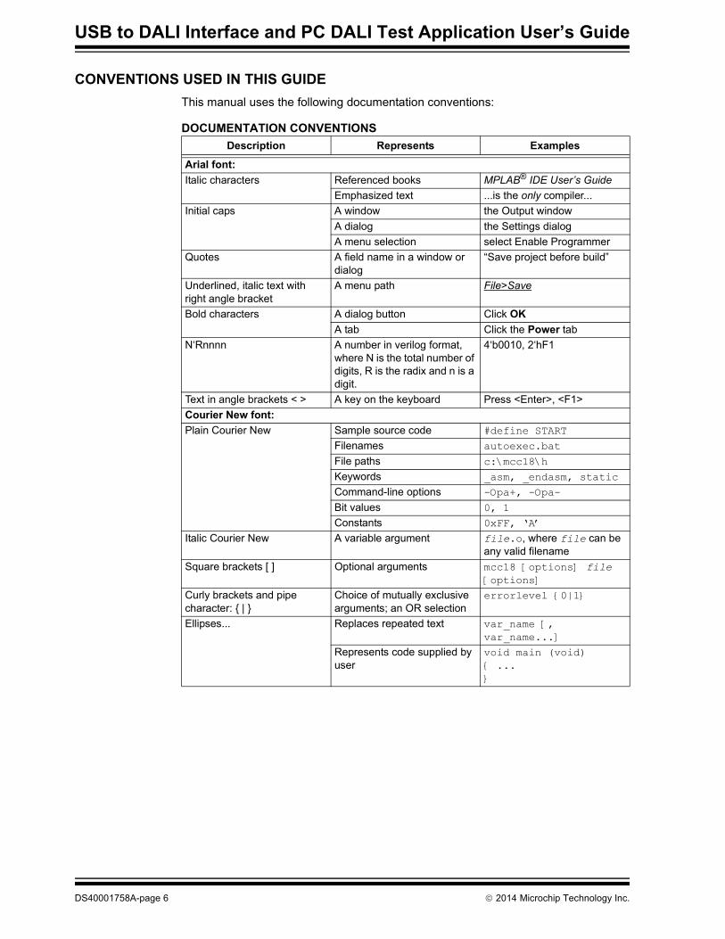
CONVENTIONS USED IN THIS GUIDEThis manual uses the following documentation conventions:
DOCUMENTATION CONVENTIONSDescription Represents Examples
Arial font:Italic characters Referenced books MPLAB® IDE User’s Guide
Emphasized text ...is the only compiler...Initial caps A window the Output window
A dialog the Settings dialogA menu selection select Enable Programmer
Quotes A field name in a window or dialog
“Save project before build”
Underlined, italic text with right angle bracket
A menu path File>Save
Bold characters A dialog button Click OKA tab Click the Power tab
N‘Rnnnn A number in verilog format, where N is the total number of digits, R is the radix and n is a digit.
4‘b0010, 2‘hF1
Text in angle brackets < > A key on the keyboard Press <Enter>, <F1>Courier New font:Plain Courier New Sample source code #define START
Filenames autoexec.bat
File paths c:\mcc18\h
Keywords _asm, _endasm, static
Command-line options -Opa+, -Opa-
Bit values 0, 1
Constants 0xFF, ‘A’
Italic Courier New A variable argument file.o, where file can be any valid filename
Square brackets [ ] Optional arguments mcc18 [options] file [options]
Curly brackets and pipe character: { | }
Choice of mutually exclusive arguments; an OR selection
errorlevel {0|1}
Ellipses... Replaces repeated text var_name [, var_name...]
Represents code supplied by user
void main (void){ ...}
DS40001758A-page 6 2014 Microchip Technology Inc.
Preface
RECOMMENDED READINGThis user’s guide assumes familiarity with DALI concepts and terminology. For further information on these subjects, the following resources can be addressed. Other useful documents are listed below. The following Microchip documents are available and recommended as supplemental reference resources.Read me FilesFor the latest information on using other tools, read the tool-specific Readme files in the Readmes subdirectory of the MPLAB® X IDE installation directory. The Readme files contain update information and known issues that may not be included in this user’s guide.• IEC 62386-102 General Requirements – Control Gear: This document
describes the protocol and methods for testing of DALI devices.• IEC 62386-207 Particular Requirements for Control Gear – LED Modules
(Device Type 6): This document establishes the specific requirements for LED modules (device type 6).
• Microchip Lighting Resources: http://www.microchip.com/lighting• DALI AG web site: http://www.dali-ag.org/
Design CenterMicrochip has a USB design center which can be found on www.microchip.com/usb.
THE MICROCHIP WEB SITEMicrochip provides online support via our web site at www.microchip.com. This web site is used as a means to make files and information easily available to customers. Accessible by using your favorite Internet browser, the web site contains the following information:• Product Support – Data sheets and errata, application notes and sample
programs, design resources, user’s guides and hardware support documents, latest software releases and archived software
• General Technical Support – Frequently Asked Questions (FAQs), technical support requests, online discussion groups, Microchip consultant program member listing
• Business of Microchip – Product selector and ordering guides, latest Microchip press releases, listing of seminars and events, listings of Microchip sales offices, distributors and factory representatives
2014 Microchip Technology Inc. DS40001758A-page 7
USB to DALI Interface and PC DALI Test Application User’s Guide
CUSTOMER SUPPORTUsers of Microchip products can receive assistance through several channels:• Distributor or Representative• Local Sales Office• Field Application Engineer (FAE)• Technical SupportCustomers should contact their distributor, representative or field application engineer (FAE) for support. Local sales offices are also available to help customers. A listing of sales offices and locations is included in the back of this document.Technical support is available through the web site at: http://support.microchip.com
DOCUMENT REVISION HISTORY
Revision A (June 2014)• Initial release of this document.
DS40001758A-page 8 2014 Microchip Technology Inc.

USB TO DALI INTERFACE AND PC DALI TESTAPPLICATION USER’S GUIDE
Chapter 1. USB to DALI Interface
1.1 HARDWARE DESCRIPTIONThe USB to DALI Interface board, presented in Figure 1-1, is based on a Microchip PIC16F1455 microcontroller and a DALI line interface circuit which provides galvanic isolation from the DALI bus. It is intended to be used with the DALI Test Application to aid in the development and debugging of DALI hardware, but is flexible enough to be used as a generic front end to a DALI bus.
FIGURE 1-1: MICROCHIP USB TO DALI INTERFACE
2014 Microchip Technology Inc. DS40001758A-page 9
USB to DALI Interface and PC DALI Test Application User’s Guide
1.2 FEATURESThe interface board supports the following:• Transmission of forward frames and reception of any backward frames that may
be generated by DALI control gears attached to the DALI bus.• Transmission of sequences of forward frames and reception of replies (if any) for
each of these. A forward frame is generated on the bus as soon as the protocol allows it after the previous communication. This is used since some commands require being sent twice within 100 ms in order to be executed. Testing defined by the DALI standard requires that multiple commands should be sent within short intervals to check the correct functionality of the DALI Control Gear.
• Reception of traffic initiated by other control devices (both forward frames as well as any backward frame that may be generated on the bus).
• Generating delays for the DALI Test Application. Some of the DALI tests require accurate timing, which can easily be generated by the microcontroller and communicated to the PC application.
• Sending of arbitrary digital waveforms on the DALI bus and checking for any DALI backward frames that may be triggered by these.
• Capture of digital waveforms from the DALI bus.• Debug mode where state changes within the DALI protocol state machine are
forwarded to the PC.
DS40001758A-page 10 2014 Microchip Technology Inc.

USB to DALI Interface
1.3 USB INTERFACEThe USB to DALI Interface board registers as a USB HID device to the PC and can communicate with the host OS without needing specialized drivers. Transfers between the PC and the USB to DALI Interface are always done in 65 byte packets, of which the first one is the report number and is always ‘0’. The firmware application only sees the last 64 bytes of these, as the USB stack drops the report number. In the following descriptions, the packet is considered to just contain these 64 bytes, making byte number 0 in the firmware correspond to byte number 1 in the PC application.The types of packets that can be sent by the application (encoded as the first byte of the packet payload) and the structures they use are outlined below, using the names they are given in the firmware. Similar names are used in the PC application. Note that all packets transferred are 64 bytes long and, most require much smaller data payloads. All unused bytes are treated as “don’t care”.
1.3.1 Types of Payload from the PC to the USB to DALI Interface• TYPE_NOTHING
Description: No operation.Payload length: 1 byte.Byte 0: Encodes the USB command “TYPE_NOTHING”.• TYPE_PING
Description: Ask for a reply in order to test the communication.Payload length: 1 byte.Byte 0: Encodes the USB command “TYPE_PING”.• TYPE_DALI_COMMAND
Description: Send command on the DALI bus.Payload length: 3 bytes.Byte 0: Encodes the USB command “TYPE_DALI_COMMAND”.Byte 1: DALI address byte.Byte 2: DALI data byte.• TYPE_STATE_QUERY
Description: Ask the DALI state machine what state it is in. Only used for USB to DALI Interface firmware debug.Payload length: 1 byte.Byte 0: Encodes the USB command “TYPE_STATE_QUERY”.
2014 Microchip Technology Inc. DS40001758A-page 11
USB to DALI Interface and PC DALI Test Application User’s Guide
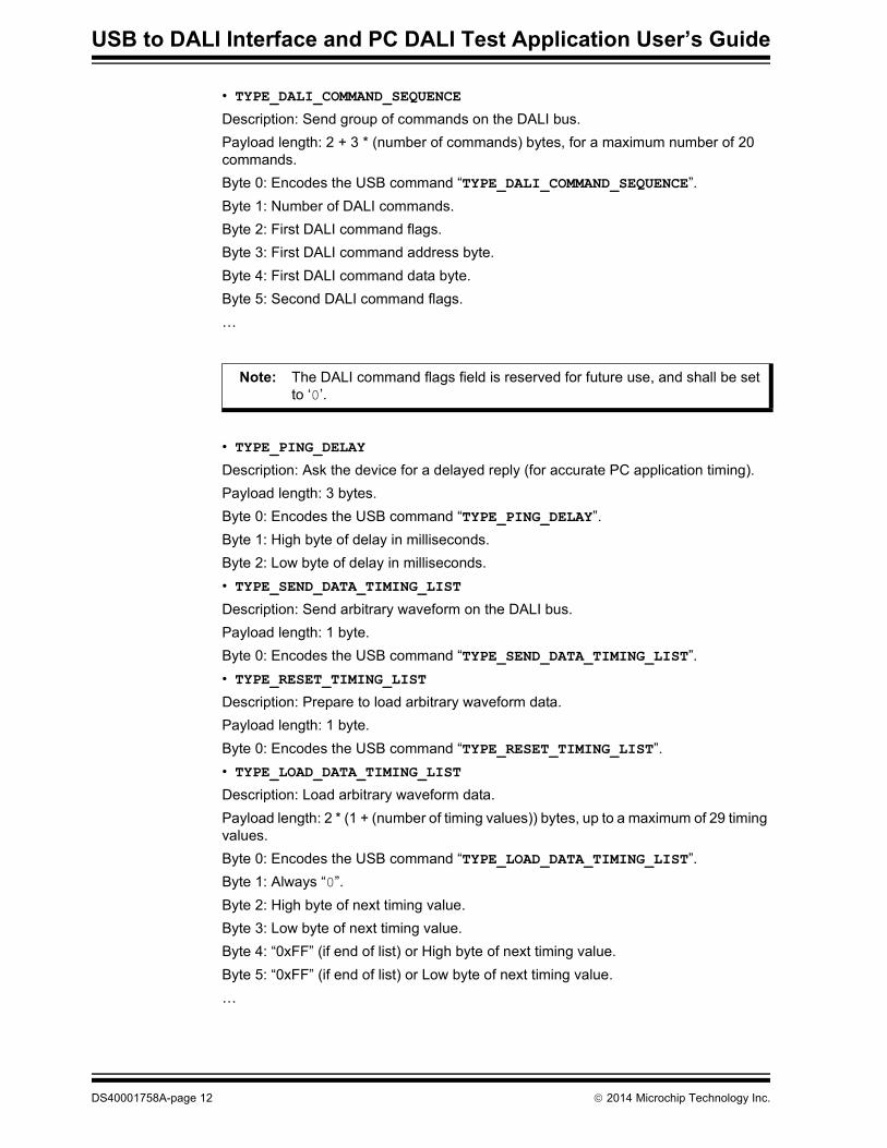
• TYPE_DALI_COMMAND_SEQUENCE
Description: Send group of commands on the DALI bus.Payload length: 2 + 3 * (number of commands) bytes, for a maximum number of 20 commands.Byte 0: Encodes the USB command “TYPE_DALI_COMMAND_SEQUENCE”.Byte 1: Number of DALI commands.Byte 2: First DALI command flags.Byte 3: First DALI command address byte.Byte 4: First DALI command data byte.Byte 5: Second DALI command flags.…
• TYPE_PING_DELAY
Description: Ask the device for a delayed reply (for accurate PC application timing).Payload length: 3 bytes.Byte 0: Encodes the USB command “TYPE_PING_DELAY”.Byte 1: High byte of delay in milliseconds.Byte 2: Low byte of delay in milliseconds.• TYPE_SEND_DATA_TIMING_LIST
Description: Send arbitrary waveform on the DALI bus.Payload length: 1 byte.Byte 0: Encodes the USB command “TYPE_SEND_DATA_TIMING_LIST”.• TYPE_RESET_TIMING_LIST
Description: Prepare to load arbitrary waveform data.Payload length: 1 byte.Byte 0: Encodes the USB command “TYPE_RESET_TIMING_LIST”.• TYPE_LOAD_DATA_TIMING_LIST
Description: Load arbitrary waveform data.Payload length: 2 * (1 + (number of timing values)) bytes, up to a maximum of 29 timing values.Byte 0: Encodes the USB command “TYPE_LOAD_DATA_TIMING_LIST”.Byte 1: Always “0”.Byte 2: High byte of next timing value.Byte 3: Low byte of next timing value.Byte 4: “0xFF” (if end of list) or High byte of next timing value.Byte 5: “0xFF” (if end of list) or Low byte of next timing value.…
Note: The DALI command flags field is reserved for future use, and shall be set to ‘0’.
DS40001758A-page 12 2014 Microchip Technology Inc.
USB to DALI Interface
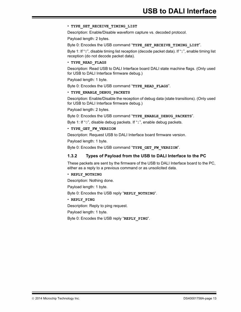
• TYPE_SET_RECEIVE_TIMING_LIST
Description: Enable/Disable waveform capture vs. decoded protocol.Payload length: 2 bytes.Byte 0: Encodes the USB command “TYPE_SET_RECEIVE_TIMING_LIST”.Byte 1: If “0”, disable timing list reception (decode packet data). If “1”, enable timing list reception (do not decode packet data).• TYPE_READ_FLAGS
Description: Read USB to DALI Interface board DALI state machine flags. (Only used for USB to DALI Interface firmware debug.)Payload length: 1 byte.Byte 0: Encodes the USB command “TYPE_READ_FLAGS”.• TYPE_ENABLE_DEBUG_PACKETS
Description: Enable/Disable the reception of debug data (state transitions). (Only used for USB to DALI Interface firmware debug.)Payload length: 2 bytes.Byte 0: Encodes the USB command “TYPE_ENABLE_DEBUG_PACKETS”.Byte 1: If “0”, disable debug packets. If “1”, enable debug packets.• TYPE_GET_FW_VERSION
Description: Request USB to DALI Interface board firmware version.Payload length: 1 byte.Byte 0: Encodes the USB command “TYPE_GET_FW_VERSION”.
1.3.2 Types of Payload from the USB to DALI Interface to the PCThese packets are sent by the firmware of the USB to DALI Interface board to the PC, either as a reply to a previous command or as unsolicited data. • REPLY_NOTHING
Description: Nothing done.Payload length: 1 byte.Byte 0: Encodes the USB reply “REPLY_NOTHING“.• REPLY_PING
Description: Reply to ping request.Payload length: 1 byte.Byte 0: Encodes the USB reply “REPLY_PING“.
2014 Microchip Technology Inc. DS40001758A-page 13
USB to DALI Interface and PC DALI Test Application User’s Guide
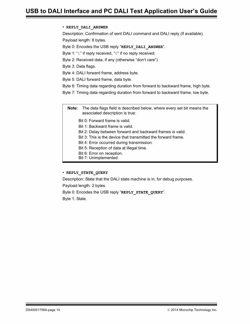
• REPLY_DALI_ANSWER
Description: Confirmation of sent DALI command and DALI reply (if available).Payload length: 8 bytes.Byte 0: Encodes the USB reply “REPLY_DALI_ANSWER“.Byte 1: “1” if reply received, “0” if no reply received.Byte 2: Received data, if any (otherwise “don’t care”)Byte 3: Data flags.Byte 4: DALI forward frame, address byte.Byte 5: DALI forward frame, data byte.Byte 6: Timing data regarding duration from forward to backward frame, high byte.Byte 7: Timing data regarding duration from forward to backward frame, low byte.
• REPLY_STATE_QUERY
Description: State that the DALI state machine is in, for debug purposes.Payload length: 2 bytes.Byte 0: Encodes the USB reply “REPLY_STATE_QUERY“.Byte 1: State.
Note: The data flags field is described below, where every set bit means the associated description is true:
Bit 0: Forward frame is valid.Bit 1: Backward frame is valid.Bit 2: Delay between forward and backward frames is valid.Bit 3: This is the device that transmitted the forward frame.Bit 4: Error occurred during transmission.Bit 5: Reception of data at illegal time.Bit 6: Error on reception.Bit 7: Unimplemented.
DS40001758A-page 14 2014 Microchip Technology Inc.

USB to DALI Interface
• REPLY_DALI_COMMAND_SEQUENCE
Description: Confirmation of sent DALI group of commands and DALI replies (if available).Payload length: 2 + 3 * (number of commands) bytes, for a maximum number of 20 commands.Byte 0: Encodes the USB reply “REPLY_DALI_COMMAND_SEQUENCE“.Byte 1: Number of DALI commands.Byte 2: “1” if first DALI command received an answer, “0” otherwise.Byte 3: first DALI command full flags.Byte 4: first DALI command answer.Byte 5: “1” if second DALI command received an answer, “0” otherwise.…
• REPLY_PING_DELAY
Description: Delayed reply.Payload length: 1 byte.Byte 0: Encodes the USB reply “REPLY_PING_DELAY“.• REPLY_SEND_DATA_TIMING_LIST
Description: Confirmation that arbitrary waveform is being sent on the DALI bus.Payload length: 1 byte.Byte 0: Encodes the USB reply “REPLY_SEND_DATA_TIMING_LIST“.• REPLY_RESET_TIMING_LIST
Description: Confirmation of preparation to load arbitrary waveform data.Payload length: 1 byte.Byte 0: Encodes the USB reply “REPLY_RESET_TIMING_LIST“.• REPLY_LOAD_DATA_TIMING_LIST
Description: Confirmation of loading arbitrary waveform data.Payload length: 1 byte.Byte 0: Encodes the USB reply “REPLY_LOAD_DATA_TIMING_LIST“.• REPLY_SET_RECEIVE_TIMING_LIST
Description: Confirmation of selection of waveform capture vs. decoded protocol.Payload length: 2 bytes.Byte 0: Encodes the USB reply “REPLY_SET_RECEIVE_TIMING_LIST“.Byte 1: “0” if timing list reception is disabled, “1” if timing list reception is enabled.
Note: The flags byte carries the same structure as byte 3 of the reply “REPLY_DALI_ANSWER”.
2014 Microchip Technology Inc. DS40001758A-page 15
USB to DALI Interface and PC DALI Test Application User’s Guide
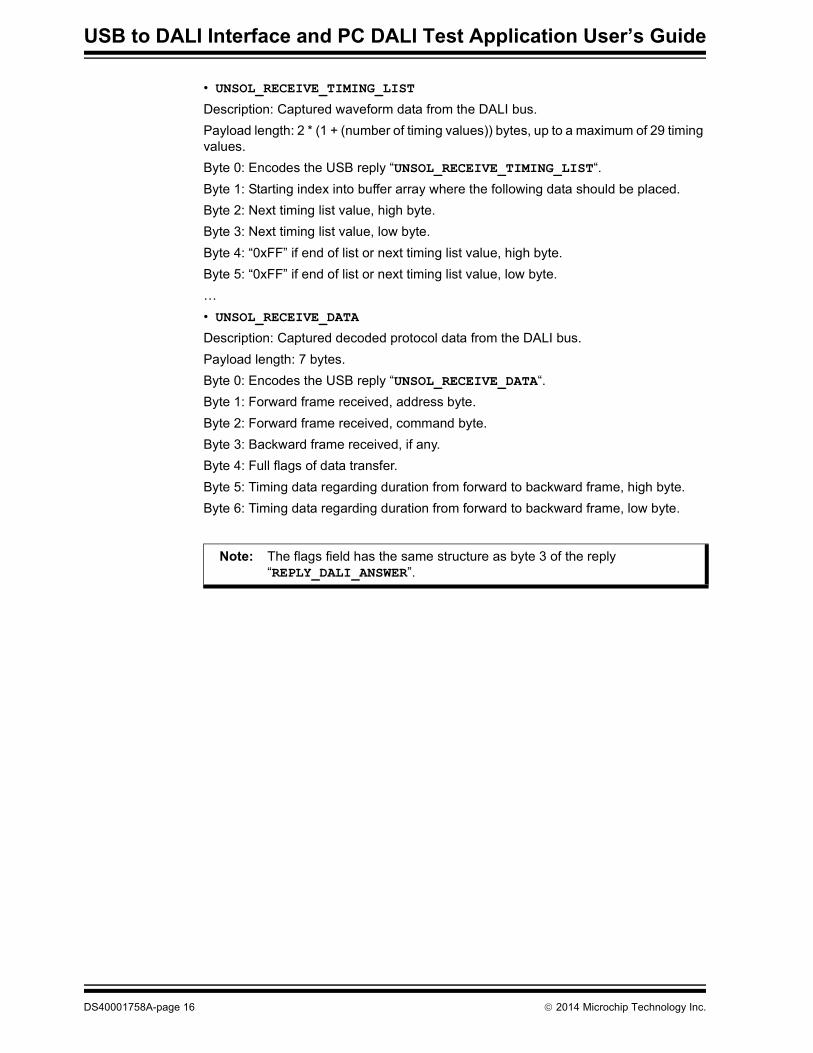
• UNSOL_RECEIVE_TIMING_LIST
Description: Captured waveform data from the DALI bus.Payload length: 2 * (1 + (number of timing values)) bytes, up to a maximum of 29 timing values.Byte 0: Encodes the USB reply “UNSOL_RECEIVE_TIMING_LIST“.Byte 1: Starting index into buffer array where the following data should be placed.Byte 2: Next timing list value, high byte.Byte 3: Next timing list value, low byte.Byte 4: “0xFF” if end of list or next timing list value, high byte.Byte 5: “0xFF” if end of list or next timing list value, low byte.…• UNSOL_RECEIVE_DATA
Description: Captured decoded protocol data from the DALI bus.Payload length: 7 bytes.Byte 0: Encodes the USB reply “UNSOL_RECEIVE_DATA“.Byte 1: Forward frame received, address byte.Byte 2: Forward frame received, command byte.Byte 3: Backward frame received, if any.Byte 4: Full flags of data transfer.Byte 5: Timing data regarding duration from forward to backward frame, high byte.Byte 6: Timing data regarding duration from forward to backward frame, low byte.
Note: The flags field has the same structure as byte 3 of the reply “REPLY_DALI_ANSWER”.
DS40001758A-page 16 2014 Microchip Technology Inc.
USB to DALI Interface
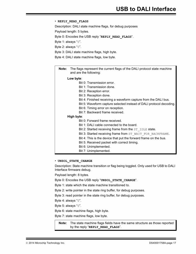
• REPLY_READ_FLAGS
Description: DALI state machine flags, for debug purposesPayload length: 5 bytes.Byte 0: Encodes the USB reply “REPLY_READ_FLAGS“.Byte 1: always “0”.Byte 2: always “0”.Byte 3: DALI state machine flags, high byte.Byte 4: DALI state machine flags, low byte.
• UNSOL_STATE_CHANGE
Description: State machine transition or flag being toggled. Only used for USB to DALI Interface firmware debug.Payload length: 8 bytes.Byte 0: Encodes the USB reply “UNSOL_STATE_CHANGE“.Byte 1: state which the state machine transitioned to.Byte 2: write pointer in the state ring buffer, for debug purposes.Byte 3: read pointer in the state ring buffer, for debug purposes.Byte 4: always “0”.Byte 5: always “0”.Byte 6: state machine flags, high byte.Byte 7: state machine flags, low byte.
Note: The flags represent the current flags of the DALI protocol state machine and are the following:
Low byte:Bit 0: Transmission error.Bit 1: Transmission done.Bit 2: Reception error.Bit 3: Reception done.Bit 4: Finished receiving a waveform capture from the DALI bus.Bit 5: Waveform capture selected instead of DALI protocol decoding.Bit 6: Timing error on reception.Bit 7: Backward frame received.
High byte:Bit 0: Forward frame received.Bit 1: DALI cable connected to the board.Bit 2: Started receiving frame from the ST_IDLE state.Bit 3: Started receiving frame from ST_WAIT_FOR_BACKFRAME.Bit 4: This is the device that put the forward frame on the bus.Bit 5: Received packet with correct timing.Bit 6: Unimplemented.Bit 7: Unimplemented.
Note: The state machine flags fields have the same structure as those reported by the reply “REPLY_READ_FLAGS”.
2014 Microchip Technology Inc. DS40001758A-page 17
USB TO DALI INTERFACE AND PC DALI TESTAPPLICATION USER’S GUIDE
Chapter 2. DALI Test Application
2.1 APPLICATION DESCRIPTIONThe DALI Test Application is a front-end to the USB to DALI Interface board. Together these give the user flexible control of the DALI bus. The application is intended to be used in the development and debugging of DALI hardware, including LED (device type 6) control gears. It provides extensive testing functionality in implementing the tests defined in the IEC 62386-102 and IEC 62386-207 documents, as well as quick access to sending custom commands on the DALI bus. The application is written in C# and can be easily modified to add custom testing scenarios. It uses the HIDAPI library for interfacing to the USB bus.
2.2 INSTALLING THE SOFTWAREThe DALI Test Application can be installed using the installation kit that can be found on the Microchip web site. Once installed, the application can be accessed from the Start menu under “All Programs DALI Test Application DALI Test Application”.
2.3 FEATURESThe DALI Test Application implements the following functionality:• Possibility to run all or only a subset of the DALI tests, as specified in IEC
62386-102 and IEC 62386-207.• Selecting DALI commands from a list or building custom DALI commands and
sending them on the DALI bus. Any answers that may be generated by control gears attached to that DALI bus are received.
• Building lists of DALI commands which will be sent in sequence on the bus.• Sniffing of DALI bus activity that other DALI control devices may generate, along
with the replies generated by control gears that may be present.• Detection of bus errors, both for traffic initiated by the application, as well as for
traffic initiated by other DALI control devices.• Decoding of DALI commands into their textual representation, both for traffic
initiated by the application and for traffic initiated by other DALI control devices.• Quick access to “DIRECT ARC POWER CONTROL” and “QUERY ACTUAL
LEVEL” commands via dedicated controls.• Color-coded console output for application status/bus activity monitoring.• Configurable verbosity.• Implements a USB to DALI Interface test procedure to check the correct
functionality of one or multiple USB to DALI Interface boards.
DS40001758A-page 18 2014 Microchip Technology Inc.
USB to DALI Interface and PC DALI Test Application User’s Guide
2.4 USAGE
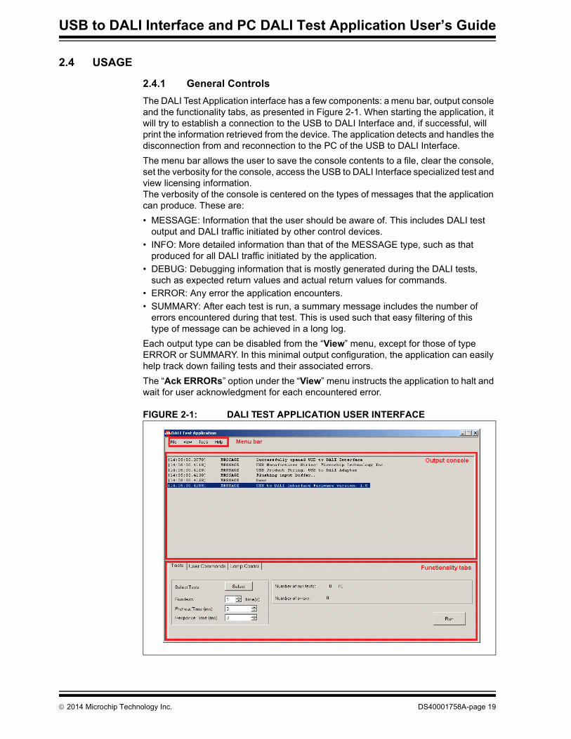
2.4.1 General ControlsThe DALI Test Application interface has a few components: a menu bar, output console and the functionality tabs, as presented in Figure 2-1. When starting the application, it will try to establish a connection to the USB to DALI Interface and, if successful, will print the information retrieved from the device. The application detects and handles the disconnection from and reconnection to the PC of the USB to DALI Interface.The menu bar allows the user to save the console contents to a file, clear the console, set the verbosity for the console, access the USB to DALI Interface specialized test and view licensing information.The verbosity of the console is centered on the types of messages that the application can produce. These are:• MESSAGE: Information that the user should be aware of. This includes DALI test
output and DALI traffic initiated by other control devices.• INFO: More detailed information than that of the MESSAGE type, such as that
produced for all DALI traffic initiated by the application.• DEBUG: Debugging information that is mostly generated during the DALI tests,
such as expected return values and actual return values for commands.• ERROR: Any error the application encounters.• SUMMARY: After each test is run, a summary message includes the number of
errors encountered during that test. This is used such that easy filtering of this type of message can be achieved in a long log.
Each output type can be disabled from the “View” menu, except for those of type ERROR or SUMMARY. In this minimal output configuration, the application can easily help track down failing tests and their associated errors.The “Ack ERRORs” option under the “View” menu instructs the application to halt and wait for user acknowledgment for each encountered error.
FIGURE 2-1: DALI TEST APPLICATION USER INTERFACE
2014 Microchip Technology Inc. DS40001758A-page 19

DALI Test Application
2.4.2 Running the DALI TestsThe DALI tests are defined in IEC 62386-102 and IEC 62386-207 and should be applied to a single Device Under Test (DUT) at a time. For details on the DALI testing procedure, please see Chapter 12 of IEC 62386-102. Most tests require multiple DALI commands to be sent in sequence, with strict timing and checking their replies. Bus communication is handled automatically, as well as checking the command replies; however, there are some physical parameters related to the DUT operation that will need to be checked by the operator. For each case, a pop-up window with measurement instructions will be visible which will instruct the user what measurement needs to be taken.Before running any tests the user needs to configure the Control Device’s specific preheat time and response time under the “Tests” tab (see Figure 2-1).
2.4.2.1 SELECTING THE TESTS
Tests that should be run are selected by pressing “Select” under the “Tests” tab, and then checking the individual tests in the popup window (see Figure 2-2). The tests are grouped by the chapter number in which they appear in either IEC 62386-102 or IEC 62386-207. The user can also use this popup window to save the current tests selection to a file or retrieve a previously saved one.The “Tests” tab also houses a control for running tests multiple times, and the “Run” button which triggers the testing procedure. During tests, the “Stop” button can be used to stop the testing procedure.
FIGURE 2-2: SELECTION OF THE DALI TESTS THAT SHOULD BE RUN
DS40001758A-page 20 2014 Microchip Technology Inc.
USB to DALI Interface and PC DALI Test Application User’s Guide
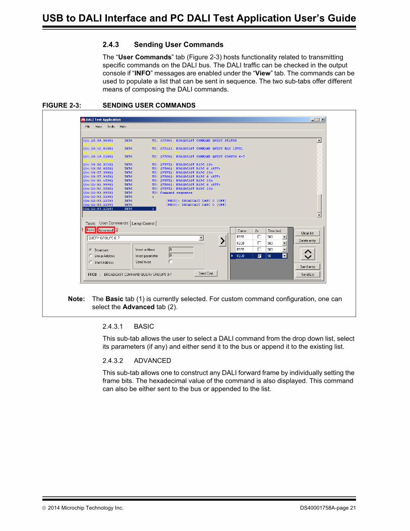
2.4.3 Sending User CommandsThe “User Commands” tab (Figure 2-3) hosts functionality related to transmitting specific commands on the DALI bus. The DALI traffic can be checked in the output console if “INFO” messages are enabled under the “View” tab. The commands can be used to populate a list that can be sent in sequence. The two sub-tabs offer different means of composing the DALI commands.
FIGURE 2-3: SENDING USER COMMANDS
2.4.3.1 BASIC
This sub-tab allows the user to select a DALI command from the drop down list, select its parameters (if any) and either send it to the bus or append it to the existing list.
2.4.3.2 ADVANCED
This sub-tab allows one to construct any DALI forward frame by individually setting the frame bits. The hexadecimal value of the command is also displayed. This command can also be either sent to the bus or appended to the list.
Note: The Basic tab (1) is currently selected. For custom command configuration, one can select the Advanced tab (2).
2014 Microchip Technology Inc. DS40001758A-page 21

DALI Test Application
2.4.4 Sending ‘DIRECT ARC POWER CONTROL’ and ‘QUERY ACTUAL LEVEL’ commands
The “Lamp Control” tab (Figure 2-4) provides controls for quick assessment of the functionality of a DALI system. Using the slider control, “DIRECT ARC POWER CONTROL” commands can be sent, whereas to send “QUERY ACTUAL LEVEL” commands, the “Query” button can be used.
These commands (both “DIRECT ARC POWER CONTROL” as well as “QUERY ACTUAL LEVEL” ones) can be sent to any valid DALI short address (0..63) or as a broadcast (using the special value ’ -1’).
FIGURE 2-4: LAMP CONTROL TAB THAT CAN BE USED TO SEND “DIRECT ARC POWER CONTROL” AND ‘QUERY ACTUAL LEVEL’ COMMANDS
Note: In order to see any reply a Control Gear may generate, you need to have “INFO” messages enabled under the “View” menu.
DS40001758A-page 22 2014 Microchip Technology Inc.

USB to DALI Interface and PC DALI Test Application User’s Guide
2.4.5 Checking the Functionality of the USB to DALI Interface Using the Specialized Test
This integrated test is available under the “Tools” menu, option “Interface Self Test” and aims to check as much of the functionality of the USB to DALI Interface board as possible. It should be started with no USB to DALI Interface board connected to the application.No other communication options are available to the user while this test is in progress and it can be closed using the “Close Extra Test” button that has replaced all tabs, as seen in Figure 2-5. While running, this test can be applied to multiple boards just by following the on-screen instructions. Note that after closing this test you need to disconnect the board from the USB bus and reconnect it in order to be able to keep using it in the application.
FIGURE 2-5: INTERFACE SELF TEST FUNCTIONALITY
2014 Microchip Technology Inc. DS40001758A-page 23

DS40001758A-page 24 2014 Microchip Technology Inc.
USB TO DALI INTERFACE AND PC DALI TESTAPPLICATION USER’S GUIDE
Appendix A. USB to DALI Interface Hardware Schematic
FIGURE A-1: USB TO DALI INTERFACE SCHEMATIC
2014 Microchip Technology Inc. DS40001758A-page 25
USB TO DALI INTERFACE AND PC DALITEST APPLICATION USER’S GUIDE
Appendix B. USB to DALI Interface Bill of Materials
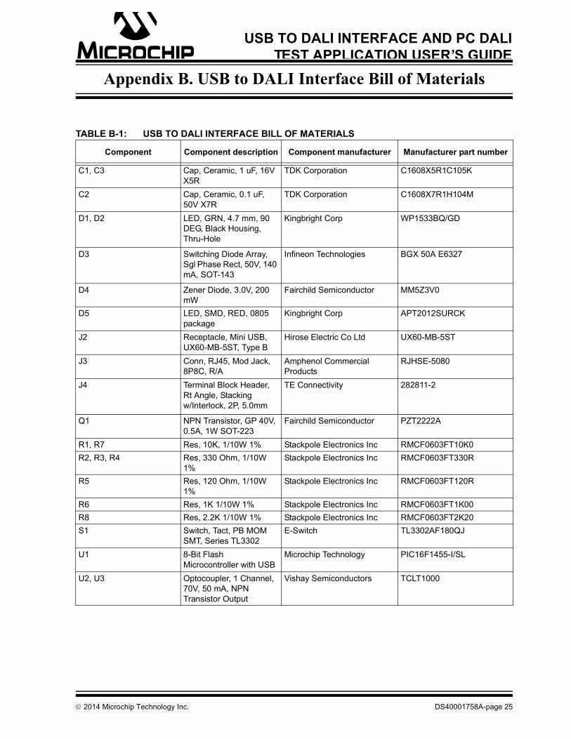
TABLE B-1: USB TO DALI INTERFACE BILL OF MATERIALS
Component Component description Component manufacturer Manufacturer part number
C1, C3 Cap, Ceramic, 1 uF, 16V X5R
TDK Corporation C1608X5R1C105K
C2 Cap, Ceramic, 0.1 uF, 50V X7R
TDK Corporation C1608X7R1H104M
D1, D2 LED, GRN, 4.7 mm, 90 DEG, Black Housing, Thru-Hole
Kingbright Corp WP1533BQ/GD
D3 Switching Diode Array, Sgl Phase Rect, 50V, 140 mA, SOT-143
Infineon Technologies BGX 50A E6327
D4 Zener Diode, 3.0V, 200 mW
Fairchild Semiconductor MM5Z3V0
D5 LED, SMD, RED, 0805 package
Kingbright Corp APT2012SURCK
J2 Receptacle, Mini USB, UX60-MB-5ST, Type B
Hirose Electric Co Ltd UX60-MB-5ST
J3 Conn, RJ45, Mod Jack, 8P8C, R/A
Amphenol Commercial Products
RJHSE-5080
J4 Terminal Block Header, Rt Angle, Stacking w/Interlock, 2P, 5.0mm
TE Connectivity 282811-2
Q1 NPN Transistor, GP 40V, 0.5A, 1W SOT-223
Fairchild Semiconductor PZT2222A
R1, R7 Res, 10K, 1/10W 1% Stackpole Electronics Inc RMCF0603FT10K0R2, R3, R4 Res, 330 Ohm, 1/10W
1%Stackpole Electronics Inc RMCF0603FT330R
R5 Res, 120 Ohm, 1/10W 1%
Stackpole Electronics Inc RMCF0603FT120R
R6 Res, 1K 1/10W 1% Stackpole Electronics Inc RMCF0603FT1K00R8 Res, 2.2K 1/10W 1% Stackpole Electronics Inc RMCF0603FT2K20S1 Switch, Tact, PB MOM
SMT, Series TL3302E-Switch TL3302AF180QJ
U1 8-Bit Flash Microcontroller with USB
Microchip Technology PIC16F1455-I/SL
U2, U3 Optocoupler, 1 Channel, 70V, 50 mA, NPN Transistor Output
Vishay Semiconductors TCLT1000
DS40001758A-page 26 2014 Microchip Technology Inc.
AMERICASCorporate Office2355 West Chandler Blvd.Chandler, AZ 85224-6199Tel: 480-792-7200 Fax: 480-792-7277Technical Support: http://www.microchip.com/supportWeb Address: www.microchip.comAtlantaDuluth, GA Tel: 678-957-9614 Fax: 678-957-1455Austin, TXTel: 512-257-3370 BostonWestborough, MA Tel: 774-760-0087 Fax: 774-760-0088ChicagoItasca, IL Tel: 630-285-0071 Fax: 630-285-0075ClevelandIndependence, OH Tel: 216-447-0464 Fax: 216-447-0643DallasAddison, TX Tel: 972-818-7423 Fax: 972-818-2924DetroitNovi, MI Tel: 248-848-4000Houston, TX Tel: 281-894-5983IndianapolisNoblesville, IN Tel: 317-773-8323Fax: 317-773-5453Los AngelesMission Viejo, CA Tel: 949-462-9523 Fax: 949-462-9608New York, NY Tel: 631-435-6000San Jose, CA Tel: 408-735-9110Canada - TorontoTel: 905-673-0699 Fax: 905-673-6509
ASIA/PACIFICAsia Pacific OfficeSuites 3707-14, 37th FloorTower 6, The GatewayHarbour City, KowloonHong KongTel: 852-2943-5100Fax: 852-2401-3431Australia - SydneyTel: 61-2-9868-6733Fax: 61-2-9868-6755China - BeijingTel: 86-10-8569-7000 Fax: 86-10-8528-2104China - ChengduTel: 86-28-8665-5511Fax: 86-28-8665-7889China - ChongqingTel: 86-23-8980-9588Fax: 86-23-8980-9500China - HangzhouTel: 86-571-8792-8115 Fax: 86-571-8792-8116China - Hong Kong SARTel: 852-2943-5100 Fax: 852-2401-3431China - NanjingTel: 86-25-8473-2460Fax: 86-25-8473-2470China - QingdaoTel: 86-532-8502-7355Fax: 86-532-8502-7205China - ShanghaiTel: 86-21-5407-5533 Fax: 86-21-5407-5066China - ShenyangTel: 86-24-2334-2829Fax: 86-24-2334-2393China - ShenzhenTel: 86-755-8864-2200 Fax: 86-755-8203-1760China - WuhanTel: 86-27-5980-5300Fax: 86-27-5980-5118China - XianTel: 86-29-8833-7252Fax: 86-29-8833-7256China - XiamenTel: 86-592-2388138 Fax: 86-592-2388130China - ZhuhaiTel: 86-756-3210040 Fax: 86-756-3210049
ASIA/PACIFICIndia - BangaloreTel: 91-80-3090-4444 Fax: 91-80-3090-4123India - New DelhiTel: 91-11-4160-8631Fax: 91-11-4160-8632India - PuneTel: 91-20-3019-1500Japan - OsakaTel: 81-6-6152-7160 Fax: 81-6-6152-9310Japan - TokyoTel: 81-3-6880- 3770 Fax: 81-3-6880-3771Korea - DaeguTel: 82-53-744-4301Fax: 82-53-744-4302Korea - SeoulTel: 82-2-554-7200Fax: 82-2-558-5932 or 82-2-558-5934Malaysia - Kuala LumpurTel: 60-3-6201-9857Fax: 60-3-6201-9859Malaysia - PenangTel: 60-4-227-8870Fax: 60-4-227-4068Philippines - ManilaTel: 63-2-634-9065Fax: 63-2-634-9069SingaporeTel: 65-6334-8870Fax: 65-6334-8850Taiwan - Hsin ChuTel: 886-3-5778-366Fax: 886-3-5770-955Taiwan - KaohsiungTel: 886-7-213-7830Taiwan - TaipeiTel: 886-2-2508-8600 Fax: 886-2-2508-0102Thailand - BangkokTel: 66-2-694-1351Fax: 66-2-694-1350
EUROPEAustria - WelsTel: 43-7242-2244-39Fax: 43-7242-2244-393Denmark - CopenhagenTel: 45-4450-2828 Fax: 45-4485-2829France - ParisTel: 33-1-69-53-63-20 Fax: 33-1-69-30-90-79Germany - DusseldorfTel: 49-2129-3766400Germany - MunichTel: 49-89-627-144-0 Fax: 49-89-627-144-44Germany - PforzheimTel: 49-7231-424750Italy - Milan Tel: 39-0331-742611 Fax: 39-0331-466781Italy - VeniceTel: 39-049-7625286 Netherlands - DrunenTel: 31-416-690399 Fax: 31-416-690340Poland - WarsawTel: 48-22-3325737 Spain - MadridTel: 34-91-708-08-90Fax: 34-91-708-08-91Sweden - StockholmTel: 46-8-5090-4654UK - WokinghamTel: 44-118-921-5800Fax: 44-118-921-5820
Worldwide Sales and Service
03/25/14
Top Related