


Languages
Pages
Legal


N E T W O R K C A B L I N G S O L U T I O N S C A T A L O G
W W W . S I E M O N . C O M
SIE
MO
N S
YS
TE
M C
AT
AL
OG
Cover_2010_Final:Layout 1 2/12/10 4:27 PM Page 2
In 1903, Carl Siemon launched The Siemon Company on the
strength of his own innovative plastic compounds and soon
began pioneering new telecommunication technologies.
Over a century later that spirit of innovation is still at the core
of everything we do at Siemon – driving us to
develop the most forward-looking, high-quality line of
network cabling solutions in the world.
This catalog represents over a century of Siemon
expertise, detailing the latest innovations and key
products in each of Siemon’s high-performance cabling sys-
tems.
Siemon InnovationInspired by our past, focused on the future
New in this edition:
�Revolutionary Z-MAX™ Copper Cabling System
�VersaPOD™ Data Center Cabinet Solution
�XLR8™ Mechanical Splice Fiber Optic Termination System
�Enhanced and expanded Fiber Optic Plug and Play Line
� MapIT™ G2 – Next-Generation Intelligent Infrastructure Management Solution
� LockIT™ Secure Connectivity System
Cover_2010_Final:Layout 1 2/12/10 4:27 PM Page 3
www.siemon.com
TA
BL
E O
F C
ON
TE
NT
S
Category 7A/ClassFA Products . . . . . . . . . . . . . . . . . . . .
Z-MAX™ Category 6A Network Cabling Solutions . . . . .
Premium 6 and System 6 UTP . . . . . . . . . . . . . . . . . . . . .
Premium 5® F/UTP and System 5e® . . . . . . . . . . . . . . . .
Premium 5® and System 5e® UTP . . . . . . . . . . . . . . . . .
Fiber Cable Assemblies . . . . . . . . . . . . . . . . . . . . . . . . . .
Fiber Enclosures and Splicing . . . . . . . . . . . . . . . . . . . .
MapIT® G2 Infrastructure Management . . . . . . . . . . . . .
Faceplates and Mounting Accessories . . . . . . . . . . . . .
VersaPOD™, Racks and Cable Management . . . . . . . . .
Industrial Product . . . . . . . . . . . . . . . . . . . . . . . . . . . . . . .
Tools and Testers . . . . . . . . . . . . . . . . . . . . . . . . . . . . . . .
Glossary/Warranty . . . . . . . . . . . . . . . . . . . . . . . . . . . . . .
Index . . . . . . . . . . . . . . . . . . . . . . . . . . . . . . . . . . . . . . . . .
1.0
2.0
3.0
4.0
5.0
6.0
7.0
8.0
9.0
10.0
11.0
12.0
13.0
14.0
TOC_Final.qxd:ZMax_Catalog 1/4/10 11:00 AM Page 1
CA
TE
GO
RY
7A
/CL
AS
S F
AP
RO
DU
CT
S
1.0 www.siemon.com
Category 7A/Class FA Products
Exceeding ISO/IEC category 7A /class FA specifications,Siemon’s fully shielded TERA end-to-end cabling solution isthe highest-performing, most secure twisted-pair copper cabling system available. TERA supports performance beyond10Gb/s and passes stringent TEMPEST security testing.
Beyond industry best speed and best total cost of ownership,TERA’s unique cable-sharing ability in support of lower speedapplications results in a more “Green” solution and can alsoprovide up-front savings through the reduction of cablecounts. By combining the use of one TERA outlet dedicatedfor high-speed applications of 10Gb/s and beyond and anotherfor cable sharing of lower speed voice and video applications,end-users simultaneously benefit from the highest performingand most cost effective copper solution.
The only non-RJ connector approved as a category 7A/classFA interface, TERA fits within a standard RJ45 footprint and iseasily connected to RJ45 equipped electronics via TERA to RJpatch cords.
SECTION CONTENTS
TERA 4-Pair Outlet . . . . . . . . . . . . . . . . . . . . . . . . . . . . . . . . . . . . . . . .1.2
TERA-MAX® Patch Panels . . . . . . . . . . . . . . . . . . . . . . . . . . . . . . . . . . .1.3
TERA Patch Cords . . . . . . . . . . . . . . . . . . . . . . . . . . . . . . . . . . . .1.4 – 1.5
TERA Video Baluns . . . . . . . . . . . . . . . . . . . . . . . . . . . . . . . . . . . . . . . .1.5
TERA S/FTP Trunking Cable Assemblies . . . . . . . . . . . . . . . . . . . . . . . .1.6
TERA S/FTP 1000 MHz Cables (US) . . . . . . . . . . . . . . . . . . . . . . . . . . .1.7
TERA S/FTP 1000 MHz Cables (International) . . . . . . . . . . . . . . . . . . . .1.8
01_TERA_2010.qxd:ZMax_Catalog 1/4/10 11:06 AM Page 1

www.siemon.com
CA
TE
GO
RY
7A
/CL
AS
S F
A®
PR
OD
UC
TS
1.1
1
2 3
4
5
6
7
8
Easy InstallationCPT-T tool reduces preparation andtermination time.
Mounting OptionsThe TERA outlet is compatible with TERA-MAX® patch panels and all MAX seriesfaceplates.
Quick-Ground™
TerminationNo additional steps required fortermination. Cable shield is automaticallyterminated within the outlet withoutadditional steps or tools.
Bend Relief — Rear boot provides bend relief for cable exiting theplug and outlet
Fully Shielded — Terminates fully shielded (F/FTP and S/FTP)cable — virtually eliminates alien crosstalk
Shielded Termination — Connector automatically assures propertermination of cable shield — no additional processes required forgrounding cable
Compact Design — Slim, compact design allows outlets to beside-stacked and inserted from either the front or rear of faceplates
Hinged Door — Outlets include a hinged door to prevent exposureto dust and other contaminates
Quadrant Isolation — Shielded quadrant design fully isolatespairs for optimum NEXT performance
Application Sharing — TERA’s ability to support multipleapplications over a single 4-pair cable and outlet can savesignificant material and installation costs
TEMPEST Security Tested — The TERA system is the first andonly copper system to pass TEMPEST emissions testing by anindependent, NSA certified lab, Dayton T. Brown Inc.
1 5
62
3
4
7
8
TERA Outlet
Invented by Siemon in 1999 and subsequently chosen as anindustry standard interface for category 7/class F andcategory 7A /class FA, the Siemon TERA outlet is by far thehighest performing twisted-pair copper connector in theworld. When installed as part of a TERA solution, each pairdelivers 1.2 GHz per pair — exceeding category 7A /class FAspecifications. This extra bandwidth supports demandingapplications like broadband video, with an upper frequencyrequirement of 862 MHz.
01_TERA_2010.qxd:ZMax_Catalog 1/4/10 11:06 AM Page 2

CA
TE
GO
RY
7A
/CL
AS
S F
AP
RO
DU
CT
S
1.2 www.siemon.com
TERA Cable SharingUp to four simultaneous applications can be served from a single 4-pair, S/FTP cable andTERA outlet, saving significant materials, labor, pathway and rack space.
TERA 4-Pair OutletTERA outlets are the industry’s highest performing network cablingconnectors. Outlets accept 1-, 2- and 4-pair plugs and terminate fully shieldedcategory 7 and 7A cables. TERA outlets can be used in both the work area andin the telecommunications room.
Part # DescriptionT7F-01-1. . . . . . . . . . . . . . . . . . TERA 4-pair outlet with black door, latch and boot. Compatible with 0.64-0.55mm
(22-23 AWG) solid S/FTP and F/FTP cable
10/100 Ethernet
(2-pair)
Broadband Video
(1-pair)
Voice
(1-pair)
One TERA replaces four 1-pair analog voice outlets — perfect for call or fax centers.
01_TERA_2010.qxd:ZMax_Catalog 1/4/10 11:06 AM Page 3

www.siemon.com
CA
TE
GO
RY
7A
/CL
AS
S F
AP
RO
DU
CT
S
1.3
TERA-MAX Patch Panels
TERA-MAX 19 inch patch panels provide outstanding performanceand reliability in a shielded, high-density modular solution. Asoutlets are snapped into place, resilient ground tabs assure that eachoutlet is properly grounded. No secondary outlet groundingoperations are required, reducing overall installation time.
TERA-MAX PATCH PANELS
Part # DescriptionTM-PNLZ-24-01 . . . . . . . . .24-port TERA-MAX panel, black, 1U
TM-PNLZ-24 . . . . . . . . . . . .24-port TERA-MAX panel, metallic, 1U
TM-PNLZA-24-01 . . . . . . . .24-port Angled TERA-MAX panel, black, 1U
TM-PNLZA-24 . . . . . . . . . .24-port Angled TERA-MAX panel, metallic, 1U
Panels include designation labels, cable ties and mounting hardware.
Note: 1U = 44.5mm (1.75 in.)
1 2
3
45
Cable ManagementIntegral rear cable manager facilitates theorderly routing of horizontal cables as wellas maintaining proper bend radius foroptimum performance.
Slim DesignUse TERA outlets in TERA-MAX patch panelfor telecommunications room applications.
Integrated GroundingPanels feature integrated grounding viaresilient ground tabs engaged duringmodule insertion.
Standard Fit — Panels can be mounteddirectly on standard 19 inch relay rack orcabinet
Durable — Lightweight, high strength steelwith black or metallic finish
High Density — 24 10Gb/s ports in only1U — up to 96 ports with cable sharing
Installation Friendly — Individual modulessnap into place, providing integratedgrounding without additional steps
Port Identification — Bold port numberingenables quick identification of outlets
Angled TERA-MAX — Allows direct routingof cables to vertical managers, eliminatingthe need for horizontal cable managers
1
2
3
4
5
6
6
01_TERA_2010.qxd:ZMax_Catalog 1/4/10 11:06 AM Page 4
CA
TE
GO
RY
7A
/CL
AS
S F
AP
RO
DU
CT
S
1.4 www.siemon.com
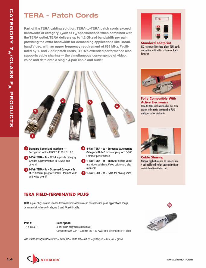
Standard FootprintISO recognized interface allows TERA cordsand outlets to fit within a standard RJ45footprint.
Fully Compatible WithActive ElectronicsTERA to RJ45 patch cords allow the TERAsystem to be easily connected to RJ45equipped active electronics.
TERA - Patch Cords
Part of the TERA cabling solution, TERA-to-TERA patch cords exceedbandwidth of category 7A/class FA specifications when combined withthe TERA outlet. TERA delivers up to 1.2 GHz of bandwidth per pair,providing the extra bandwidth for demanding applications like Broad-band Video, with an upper frequency requirement of 862 MHz. Facili-tated by 1- and 2-pair patch cords, TERA’s extended performance alsosupports cable sharing — the simultaneous convergence of video,voice and data onto a single 4-pair cable and outlet.
Cable SharingMultiple applications can be run over one4-pair cable and outlet, saving significantmaterial and installation cost.
1
2
3
4
56
Standard Compliant Interface —Recognized within ISO/IEC 11801 Ed. 2.0
4-Pair TERA - to - TERA supports category7A/class FA performance to 10Gb/s andbeyond
2-Pair TERA - to - Screened Category 5eMC® modular plug for 10/100 Ethernet, VoIPand video over IP
4-Pair TERA - to - Screened AugmentedCategory 6A MC modular plug for 1G/10GEthernet performance
1-Pair TERA - to - TERA for analog voiceand video patching. Video balun cord alsoavailable
1-Pair TERA - to - RJ11 for analog voice
1
2
3
4
5
6
TERA FIELD-TERMINATED PLUG
TERA 4-pair plugs can be used to terminate horizontal cable in consolidation point applications. Plugsterminate fully shielded category 7 and 7A solid cable.
Part # DescriptionT7P4-B(XX)-1 4-pair TERA plug with colored boot.
Compatible with 0.64 – 0.55mm (22 – 23 AWG) solid S/FTP and F/FTP cable
Use (XX) to specify boot color: 01 = black, 02 = white, 03 = red, 05 = yellow, 06 = blue, 07 = green
01_TERA_2010.qxd:ZMax_Catalog 1/4/10 11:06 AM Page 5
www.siemon.com
CA
TE
GO
RY
7A
/CL
AS
S F
AP
RO
DU
CT
S
1.5
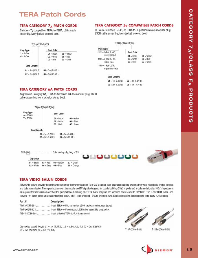
TERA Patch Cords
TERA VIDEO BALUN CORDSTERA CATV baluns provide the optimum solution for the transmission of TV or CATV signals over structured cabling systems that were historically limited to voiceand data transmission. These products convert the unbalanced TV signals designed for coaxial cabling (75 Ω impedance) to balanced signals (100 Ω impedance)as required for transmission over twisted pair (balanced) cabling. The TERA CATV adapters are specified and useable to 862 MHz. The 1-pair TERA to PAL andTERA to "F" patch cords utilize an integrated balun. The 1-pair shielded TERA to shielded RJ45 patch cord allows connection to third-party RJ45 baluns.
Part # DescriptionT1VC-(XX)M-B01L . . . . . . . . . . . 1-pair TERA-to-PAL connector, LS0H cable assembly, gray jacket
T1VF-(XX)M-B01L . . . . . . . . . . . 1-pair TERA-to-F connector, LS0H cable assembly, gray jacket
T1S4V-(XX)M-B01L . . . . . . . . . . 1-pair shielded TERA-to-RJ45 patch cord
Use (XX) to specify length: 01 = 1m (3.28 ft.), 1.5 = 1.5m (4.92 ft.), 02 = 2m (6.56 ft.), 03 = 3m (9.84 ft.), 05 = 5m (16.4 ft.) T1VF-(XX)M-B01L T1S4V-(XX)M-B01L
TERA CATEGORY 7A PATCH CORDSCategory 7A compatible, TERA-to-TERA, LS0H cableassembly, ivory jacket, colored boot.
Boot Color:
Cord Length:
01 = 1m (3.28 ft.)
02 = 2m (6.56 ft.)
03 = 3m (9.84 ft.)
05 = 5m (16.4 ft.)
01 = Black 02 = White03 = Red
05 = Yellow 06 = Blue 07 = Green
Plug Type:1 = 1-Pair 4 = 4-Pair
TERA CATEGORY 6A PATCH CORDSAugmented Category 6A, TERA-to-Screened RJ-45 modular plug, LS0Hcable assembly, ivory jacket, colored boot.
Boot Color:
Cord Length:
01 = 1m (3.28 ft.)02 = 2m (6.56 ft.)
03 = 3m (9.84 ft.)05 = 5m (16.4 ft.)
01 = Black 02 = White03 = Red
05 = Yellow 06 = Blue07 = Green
Plug Type:A = T568B T = T568A
TERA CATEGORY 5e COMPATIBLE PATCH CORDSTERA-to-Screened RJ-45, or TERA-to- 6 position (Voice) modular plug,LS0H cable assembly, ivory jacket, colored boot.
Boot Color:
Cord Length:
01 = 1m (3.28 ft.)
02 = 2m (6.56 ft.)
03 = 3m (9.84 ft.)
05 = 5m (16.4 ft.)
01 = Black02 = White03 = Red
05 = Yellow 06 = Blue 07 = Green
Plug Type:
2E2 = 2-Pair, RJ-45,10/100BASE-T
2UT = 2-Pair, RJ-45,Token Ring
1U1 = 1-Pair*, UTP, 6-position, Voice
CLIP-(XX) . . . . . . . . . . . . . . . . . . Color coding clip, bag of 25
Clip Color
01 = Black02 = White
03 = Red04 = Gray
05 = Yellow06 = Blue
07 = Green09 = Orange
T(X)-(XX)M-B(XX)L T(XXX)-(XX)M-B(XX)L
T4(X)-S(XX)M-B(XX)L
01_TERA_2010.qxd:ZMax_Catalog 1/4/10 11:06 AM Page 6

CA
TE
GO
RY
7A
/CL
AS
S F
AP
RO
DU
CT
S
1.6 www.siemon.com
6 Leg Double-Ended Trunking Cable Assemblies:
Part # DescriptionTJRD6E-F7F7(XXX)F . . . . . . . . . Riser rated (CMR), blue jacket, 1000MHz
TJPD6E-F7F7(XXX)F . . . . . . . . . Plenum rated (CMP), blue jacket, 1000MHz
TJLD8E-F7F7(XXX)F . . . . . . . . . LS0H rated (IEC 60332-1), violet jacket, 1000MHz
Use (XXX) to specify length: 009-295 ft. in increments of 3 feet
Other lengths and configurations available upon request.
Data CentersIdeal for data center, raised floor and ladderrack environments enabling up to 75% fasterdeployment time. Well organized cablebundles improve cable management and airflow
Simple, Snap-InInstallationStraight Cut aligns TERA outlets for optimalsnap in installation into TERA-MAX® patchpanels and allows left, right or center exit.
Protective PackagingEach assembly is packaged individually toprotect factory terminations.
Proper Orientation — Each leg islabeled for proper outlet orientation
Fully Shielded Cable — Utilizes highquality category 7A S/FTP Siemon cable
Factory Terminated and Tested —Utilizes TERA outlets, factory terminatedand tested for performance to 10Gb/sand beyond
Identification — Each cable assembly iscoded with a unique identificationnumber for administrative purposes
Breakout Kit — Unique breakout kitcreates optimal cable orientation andlimits cable crossing
1
2
3
4
5
STRAIGHT CUT
TERA S/FTP TRUNKING CABLE ASSEMBLIES
Note: These products are made to order. Call for lead time and part number availability in your region.
TERA - S/FTP Trunking CableAssemblies
Siemon’s TERA copper trunking cable assemblies provide an efficient andcost effective alternative to individual field-terminated components.Combining factory terminated and tested TERA outlets and fully shieldedSiemon category 7A cable, Siemon TERA trunking cable assemblies offerindustry leading performance to 10Gb/s and beyond. Standardconfigurations also help maintain consistent cable layout, facilitate efficientmoves, adds and changes and significantly reduce scrap versus typical fieldinstallation. Modular design, in conjunction with reduced scrap, makestrunks the most “Green” method for copper cabling installations.
1
2 34
5
01_TERA_2010.qxd:ZMax_Catalog 1/4/10 11:06 AM Page 7

www.siemon.com
CA
TE
GO
RY
7A
/CL
AS
S F
AP
RO
DU
CT
S
1.7
Part # Description9T7P4-E10-06-R1. . . . . . . . . . . Plenum (CMP, CSA FT6), Blue Jacket,
305m (1000 ft.) Reel
9T7R4-E10-06-R1. . . . . . . . . . . Riser (CMR, CSA FT4), Blue Jacket, 305m (1000 ft.) Reel
COMPLIANCE
• ISO/IEC 11801:2002 (Category 7)
• ISO/IEC 11801 Amendment 1 (draft)
• IEC 61156-5:2002 (Category 7)
• IEC 61156-5 Ed 2.0 (Category 7A)
• UL CMR and CSA FT4
• UL CMP and CSA FT6
CABLE CONSTRUCTION
• S/FTP
• 0.64mm (0.025 in.) (22 AWG) solid bare copper
• 8.9mm (0.35 in.) [CMR], 8.4mm (0.33 in.) [CMP]max jacket diameter
• Pairs individually shielded with aluminum-polyester foil
• Overall tinned copper braid
DC Resistance <17.0 Ω/100m
DC Resistance Unbalance 2 %
Mutual Capacitance 5.6 nF/100m
Capacitance Unbalance <330 pF/100m
Characteristic Impedance 1-100 MHz: 100 ± 15%
(ohms) 100-250 MHz: 100 ± 22%
250-1000 MHz: 100± 25%
NVP 80%
TCL 40-10 log(ƒ) dB
Delay Skew ≤20ns
ELECTRICAL SPECIFICATIONS
*Values below 4 MHz are for information only
CMP CMR
Pulling Tension (max) 110N (25 lbf) 110N (25 lbf)
Bend Radius (min) 50mm (2.0 in.) 50mm (2.0 in.)
Installation Temperature 0 to 60°C (+32 to 140°F) 0 to 60°C (+32 to 140°F)
Storage Temperature -20 to 75°C (-4 to 167°F) -20 to 75°C (-4 to 167°F)
Operating Temperature -20 to 60°C (-4 to 140°F) -20 to 60°C (-4 to 140°F)
PHYSICAL PROPERTIES
All performance based on 100 meters (328 ft.).
Frequency Insertion Loss NEXT PS NEXT ACR PSACR ACR-F PS ACR-F Return Loss Propagation(MHz) (dB) (dB) (dB) (dB) (dB) (dB) (dB) (dB) Delay
(ns)
1.0* 2.1 1.7 78.0 100.0 75.0 97.0 75.9 98.3 72.9 95.3 78.0 90.0 75.0 87.0 20.0 30.0 512 4924.0 3.7 3.4 78.0 100.0 75.0 97.0 74.3 96.6 71.3 93.6 78.0 90.0 75.0 87.0 23.0 33.0 494 474
10.0 5.8 5.0 78.0 100.0 75.0 97.0 72.2 95.0 69.2 92.0 74.0 90.0 71.0 87.0 25.0 35.0 487 46716.0 7.3 6.4 78.0 100.0 75.0 97.0 70.7 93.6 67.7 90.6 69.9 90.0 66.9 87.0 25.0 35.0 485 46520.0 8.2 7.1 78.0 100.0 75.0 97.0 69.8 92.9 66.8 89.9 68.0 90.0 65.0 87.0 25.0 35.0 484 46431.25 10.3 9.0 78.0 100.0 75.0 97.0 67.7 91.0 64.7 88.0 64.1 90.0 61.1 87.0 23.6 33.6 482 46262.5 14.6 13.0 75.5 100.0 72.5 97.0 60.9 87.0 57.9 84.0 58.1 85.0 55.1 82.0 21.5 31.5 481 461
100.0 18.5 16.8 72.4 98.0 69.4 95.0 53.9 81.2 50.9 78.2 54.0 81.0 51.0 78.0 20.1 30.1 480 460200.0 26.5 23.9 67.9 93.0 64.9 90.0 41.4 69.1 38.4 66.1 48.0 77.0 45.0 74.0 18.0 28.0 479 459250.0 29.7 28.5 66.4 92.1 63.4 89.1 36.7 63.6 33.7 60.6 46.0 76.0 43.0 73.0 17.3 27.3 478 458300.0 32.7 29.2 65.2 91.0 62.2 88.0 32.6 61.8 29.6 58.8 44.5 71.0 41.5 68.0 17.3 27.3 478 458350.0 35.4 31.8 64.2 90.3 61.2 87.3 28.8 58.5 25.8 55.5 43.1 69.0 40.1 66.0 17.3 27.3 478 458400.0 38.0 33.4 63.4 89.1 60.4 86.1 25.4 55.7 22.4 52.7 42.0 68.1 39.0 65.1 17.3 27.3 478 458550.0 45.0 37.2 61.3 87.3 58.3 84.3 16.3 50.1 13.3 47.1 39.2 66.2 36.2 63.1 17.3 27.3 478 458600.0 47.1 42.5 60.7 86.1 57.7 83.1 13.6 43.6 10.6 40.6 38.4 60.0 35.4 57.0 17.3 27.3 477 458800.0 54.9 48.2 58.9 83.1 55.9 80.1 3.9 34.9 0.9 31.9 35.9 52.1 32.9 49.1 16.1 27.3 477 457900.0 58.5 53.8 58.1 82.0 55.1 79.0 -0.4 28.2 -3.4 25.2 34.9 48.0 31.9 45.0 15.5 25.0 477 456
1000.0 61.9 57.5 57.4 81.0 54.4 78.0 -4.5 23.5 -7.5 20.5 34.0 46.0 31.0 43.0 15.1 24.0 477 456
TRANSMISSION PERFORMANCE GUARANTEED WORST CASE SIEMON TYPICAL
TERA S/FTP 1000 MHz4-Pair Cable (US)
01_TERA_2010.qxd:ZMax_Catalog 1/4/10 11:07 AM Page 8
CA
TE
GO
RY
7A
/CL
AS
S F
AP
RO
DU
CT
S
1.8 www.siemon.com
TRANSMISSION PERFORMANCE ISO/IEC SIEMON TYPICAL
*Values below 4 MHz are for information only
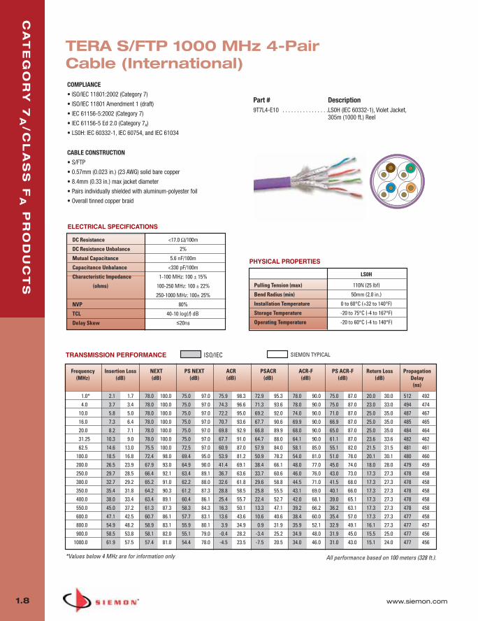
COMPLIANCE
• ISO/IEC 11801:2002 (Category 7)
• ISO/IEC 11801 Amendment 1 (draft)
• IEC 61156-5:2002 (Category 7)
• IEC 61156-5 Ed 2.0 (Category 7A)
• LS0H: IEC 60332-1, IEC 60754, and IEC 61034
CABLE CONSTRUCTION
• S/FTP
• 0.57mm (0.023 in.) (23 AWG) solid bare copper
• 8.4mm (0.33 in.) max jacket diameter
• Pairs individually shielded with aluminum-polyester foil
• Overall tinned copper braid
LS0H
Pulling Tension (max) 110N (25 lbf)
Bend Radius (min) 50mm (2.0 in.)
Installation Temperature 0 to 60°C (+32 to 140°F)
Storage Temperature -20 to 75°C (-4 to 167°F)
Operating Temperature -20 to 60°C (-4 to 140°F)
PHYSICAL PROPERTIES
Part # Description9T7L4-E10 . . . . . . . . . . . . . . . .LS0H (IEC 60332-1), Violet Jacket,
305m (1000 ft.) Reel
DC Resistance <17.0 Ω/100m
DC Resistance Unbalance 2 %
Mutual Capacitance 5.6 nF/100m
Capacitance Unbalance <330 pF/100m
Characteristic Impedance 1-100 MHz: 100 ± 15%
(ohms) 100-250 MHz: 100 ± 22%
250-1000 MHz: 100± 25%
NVP 80%
TCL 40-10 log(f) dB
Delay Skew ≤20ns
ELECTRICAL SPECIFICATIONS
All performance based on 100 meters (328 ft.).
TERA S/FTP 1000 MHz 4-PairCable (International)
Frequency Insertion Loss NEXT PS NEXT ACR PSACR ACR-F PS ACR-F Return Loss Propagation(MHz) (dB) (dB) (dB) (dB) (dB) (dB) (dB) (dB) Delay
(ns)
1.0* 2.1 1.7 78.0 100.0 75.0 97.0 75.9 98.3 72.9 95.3 78.0 90.0 75.0 87.0 20.0 30.0 512 4924.0 3.7 3.4 78.0 100.0 75.0 97.0 74.3 96.6 71.3 93.6 78.0 90.0 75.0 87.0 23.0 33.0 494 474
10.0 5.8 5.0 78.0 100.0 75.0 97.0 72.2 95.0 69.2 92.0 74.0 90.0 71.0 87.0 25.0 35.0 487 46716.0 7.3 6.4 78.0 100.0 75.0 97.0 70.7 93.6 67.7 90.6 69.9 90.0 66.9 87.0 25.0 35.0 485 46520.0 8.2 7.1 78.0 100.0 75.0 97.0 69.8 92.9 66.8 89.9 68.0 90.0 65.0 87.0 25.0 35.0 484 46431.25 10.3 9.0 78.0 100.0 75.0 97.0 67.7 91.0 64.7 88.0 64.1 90.0 61.1 87.0 23.6 33.6 482 46262.5 14.6 13.0 75.5 100.0 72.5 97.0 60.9 87.0 57.9 84.0 58.1 85.0 55.1 82.0 21.5 31.5 481 461
100.0 18.5 16.8 72.4 98.0 69.4 95.0 53.9 81.2 50.9 78.2 54.0 81.0 51.0 78.0 20.1 30.1 480 460200.0 26.5 23.9 67.9 93.0 64.9 90.0 41.4 69.1 38.4 66.1 48.0 77.0 45.0 74.0 18.0 28.0 479 459250.0 29.7 28.5 66.4 92.1 63.4 89.1 36.7 63.6 33.7 60.6 46.0 76.0 43.0 73.0 17.3 27.3 478 458300.0 32.7 29.2 65.2 91.0 62.2 88.0 32.6 61.8 29.6 58.8 44.5 71.0 41.5 68.0 17.3 27.3 478 458350.0 35.4 31.8 64.2 90.3 61.2 87.3 28.8 58.5 25.8 55.5 43.1 69.0 40.1 66.0 17.3 27.3 478 458400.0 38.0 33.4 63.4 89.1 60.4 86.1 25.4 55.7 22.4 52.7 42.0 68.1 39.0 65.1 17.3 27.3 478 458550.0 45.0 37.2 61.3 87.3 58.3 84.3 16.3 50.1 13.3 47.1 39.2 66.2 36.2 63.1 17.3 27.3 478 458600.0 47.1 42.5 60.7 86.1 57.7 83.1 13.6 43.6 10.6 40.6 38.4 60.0 35.4 57.0 17.3 27.3 477 458800.0 54.9 48.2 58.9 83.1 55.9 80.1 3.9 34.9 0.9 31.9 35.9 52.1 32.9 49.1 16.1 27.3 477 457900.0 58.5 53.8 58.1 82.0 55.1 79.0 -0.4 28.2 -3.4 25.2 34.9 48.0 31.9 45.0 15.5 25.0 477 456
1000.0 61.9 57.5 57.4 81.0 54.4 78.0 -4.5 23.5 -7.5 20.5 34.0 46.0 31.0 43.0 15.1 24.0 477 456
01_TERA_2010.qxd:ZMax_Catalog 1/4/10 11:07 AM Page 9

www.siemon.com
CA
TE
GO
RY
7A
/CL
AS
S F
AP
RO
DU
CT
S
1.9
01_TERA_2010.qxd:ZMax_Catalog 1/4/10 11:07 AM Page 10

Z-M
AX
™N
ET
WO
RK
CA
BL
ING
SO
LU
TIO
NS
2.0 www.siemon.com
Siemon’s Z-MAX NetworkCabling Solutions
The development of the Z-MAX line began with a simple goal - design and build the bestRJ-45 based cabling solution - period.
And “best” was not a vague metric. Z-MAX was built to be best across the board:
� Highest performance margins across all critical transmission parameters
� Fastest, easiest and most reliable termination process
� Superior transmission consistency
� The best customer focused usability, efficiency and ergonomic features
To meet these goals, we did what we have done for over a century - innovate.
As you explore the Z-MAX line, you’ll see Siemon innovation at every turn. From our patent-pending Zero-CrossTM termination to the exclusive PCB-based smart plug technologyintegrated into every Z-MAX cord to our hybrid flat/angled outlets to the easy-to-use Z-TOOL,no opportunity to improve this family was overlooked.
SECTION CONTENTS
Z-MAX Introduction . . . . . . . . . . . . . . . . . . . . . . . . . . . . . . . . . .2.1 - 2.3
Z-MAX 6A Shielded Overview . . . . . . . . . . . . . . . . . . . . . . . . . . . . . . . .2.4
Z-MAX 6A Shielded Outlets . . . . . . . . . . . . . . . . . . . . . . . . . . . . . . . . .2.5
Z-MAX 6A Shielded Modular Cords . . . . . . . . . . . . . . . . . . . . . . . . . . .2.6
Category 6A Shielded BladePatch . . . . . . . . . . . . . . . . . . . . . . . . . . . .2.7
Z-MAX 6A Shielded Patch Panels . . . . . . . . . . . . . . . . . . . . . . . . . . . . .2.8
TERA-MAX Patch Panels . . . . . . . . . . . . . . . . . . . . . . . . . . . . . . . . . . . .2.9
Z-MAX 6A Preterminated Shielded Trunk Cable . . . . . . . . . . . . . . . . .2.10
Category 6A F/UTP Cable (North America) . . . . . . . . . . . . . . . . . . . .2.11
Category 6A F/UTP Cable (South/Central America) . . . . . . . . . . . . . .2.12
Z-MAX 6A UTP Overview . . . . . . . . . . . . . . . . . . . . . . . . . . . . . . . . .2.12
Z-MAX 6A UTP Outlets . . . . . . . . . . . . . . . . . . . . . . . . . . . . . . . . . . .2.13
Z-MAX 6A UTP Modular Cords . . . . . . . . . . . . . . . . . . . . . . . . . . . . .2.14
Category 6A UTP BladePatch . . . . . . . . . . . . . . . . . . . . . . . . . . . . . .2.15
Z-MAX 6A UTP Patch Panels . . . . . . . . . . . . . . . . . . . . . . . . . . . . . . .2.16
Z-MAX 6A UTP Trunk Cable Assembly . . . . . . . . . . . . . . . . . . . . . . . .2.17
Category 6A UTP Cable (Americas) . . . . . . . . . . . . . . . . . . . . . . . . . .2.18
02_ZMax.qxd:02_ZMAX 2/12/10 3:18 PM Page 1

www.siemon.com
Z-M
AX
™N
ET
WO
RK
CA
BL
ING
SO
LU
TIO
NS
2.1
DON’T BLINKBest-in-class category 6A performance for UTP and Shielded in as little as 60 seconds
0:30 sec.Prep cable and place into Z-MAX’s patent-pending Zero-CrossTM lacing cap. Close hinged cable retention/grounding clip.
0:45 sec.Lace conductor pairs into color-codedlinear lacing channels and trim excess.
0:60 sec.Insert lacing cap into Z-MAX outlet andterminate with the one-step Z-TOOLTM.
1
Complete!
2
3
02_ZMax.qxd:02_ZMAX 2/12/10 3:18 PM Page 2

Z-M
AX
™N
ET
WO
RK
CA
BL
ING
SO
LU
TIO
NS
2.2 www.siemon.com
Siemon Innovations that make it possible. . .
Highest-Performing Category 6A Systems With Z-MAX, Siemon has shattered the RJ-45 bar-rier. We have achieved best-in-class performancethrough an innovative “matched” system whichcombines an optimally tuned plug with a higherperformance outlet.
� Best UTP and F/UTP category 6A margins
� Leading performance on all parameters, not just NEXT
� Exceptional alien crosstalk performance
� TIA channel, link compliant
� ISO channel, link (draft) compliant
� Consistent, superior performance,
eliminates marginal reporting (*PASS)
� Patent pending PCB-based plug enables performance levels not
possible with traditional cords
� Narrower NEXT range provides capability to tune to higher channel
performance levels
� Advanced contact technology and automated assembly results in
decreased performance variability compared with crimp-type plugs
� Smart-Plug is fully backwards-compatible and standards compliant
� PCB-based contacts eliminate pair-crossing condition present in
traditional cords
Patent-Pending Smart Plug Technology
A critical element of Z-MAX systems’ exceptional performance is our smart-plug technology. The Z-MAX smart plug contains a tuned printed circuit board (PCB), normally only found in out-lets, to achieve high performance tuning. This advancement in miniaturization has packaged thetuning capability and consistency of a PCB in an industry standard RJ-45 footprint, giving the Z-MAX patch cord unsurpassed performance capabilities.
Z-MAX 6A UTP
Z-MAX 6A F/UTP
ILNEXTPSNEXTACR-FPSACR-FRLPSANEXTPSAACR-FACR-NPSACR-N
3 %3.0 dB3.5 dB7 dB10 dB3 dB1 dB1 dB6 dB6.5 dB
3 %3.0 dB3.5 dB7 dB10 dB3 dB10 dB5 dB6 dB6.5 dB
Performance based on use of 2M cords and 24 cords and 24 port /1U density. Because we continually improve our product, Siemon reserves the right tochange specifications and availability without prior notice.
Eliminates pairuntwist required in
standard RJ-45 plugs
02_ZMax.qxd:02_ZMAX 2/12/10 3:18 PM Page 3
www.siemon.com
Z-M
AX
™N
ET
WO
RK
CA
BL
ING
SO
LU
TIO
NS
2.3
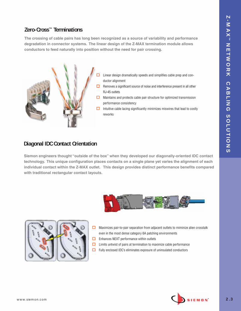
� Linear design dramatically speeds and simplifies cable prep and con-
ductor alignment
� Removes a significant source of noise and interference present in all other
RJ-45 outlets
� Maintains and protects cable pair structure for optimized transmission
performance consistency
� Intuitive cable lacing significantly minimizes miswires that lead to costly
reworks
The crossing of cable pairs has long been recognized as a source of variability and performancedegradation in connector systems. The linear design of the Z-MAX termination module allowsconductors to feed naturally into position without the need for pair crossing.
Zero-Cross™ Terminations
Siemon engineers thought “outside of the box” when they developed our diagonally-oriented IDC contacttechnology. This unique configuration places contacts on a single plane yet varies the alignment of eachindividual contact within the Z-MAX outlet. This design provides distinct performance benefits comparedwith traditional rectangular contact layouts.
Diagonal IDC Contact Orientation
� Maximizes pair-to-pair separation from adjacent outlets to miminize alien crosstalk
even in the most dense category 6A patching environments
� Enhances NEXT performance within outlets
� Limits untwist of pairs at termination to maximize cable performance
� Fully enclosed IDC’s eliminates exposure of uninsulated conductors
02_ZMax.qxd:02_ZMAX 2/12/10 3:18 PM Page 4

2.4 www.siemon.com
Z-M
AX
™6
A S
HIE
LD
ED
Z-MAX 6A Shielded SystemFeatures and Benefits
Combining consistent best-in-class performance, unparalleled usability and speed of terminationwith the security and robust noise immunity of a shielded cabling system, Siemon’s Z-MAX 6Ashielded end-to-end solution represents the cutting edge of category 6A cabling. The Z-MAX 6Ashielded system provides the highest margins on all TIA and ISO performance requirements for category 6A/class EA, including critical alien crosstalk parameters.
Siemon’s Z-MAX 6A shielded channel consists of the shielded Z-MAX 6A outlet, Siemon category 6AF/UTP cable and Z-MAX patch panels as well as shielded, stranded or solid cord options.
Standards Compliance
� ISO/IEC 11801: 2002 Amendment 1 (Class EA)� TIA/EIA-568-B.2-10� IEEE 802.3an� UL-listed
Z-MAX 6A F/UTP PerformanceGUARANTEED 4-CONNECTOR CHANNEL MARGINS TO ISO/IEC 11801: 2002 AMENDMENT 1 (Class EA)
PARAMETER VALUEIL 3 %NEXT 3 dBPSNEXT 3.5 dBACR-F 7 dBPSACR-F 10 dBRL 3 dBPSANEXT 10 dBPSAACR-F 5 dBACR-N 6 dBPSACR-N 6 dB
02_ZMax.qxd:02_ZMAX 2/12/10 3:18 PM Page 5
www.siemon.com
Z-M
AX
™6
A S
HIE
LD
ED
2.5
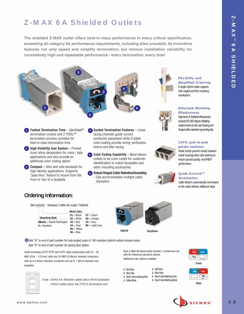
Fastest Termination Time – Zero-Cross™termination module and Z-TOOL™termination process combine for best-in-class termination time
High-Visibility Icon System – Printedicons allow designation for voice / dataapplications and also provide anadditional color coding option
Compact – Slim and side-stackable forhigh-density applications. Supports“pass-thru” feature to mount from thefront or rear of a faceplate
Guided Termination Features – Linearlacing channels guide correctconductor placement while 2-sidedcolor-coding provide wiring verificationbefore and after lacing
Color Coding Capability – Bezel allowsoutlets to be color coded for customeridentification to match faceplates andother mounting accessories
Robust Hinged Cable Retention/Grounding– Clip accommodates multiple cable
diameters
1
5
2
3
4
Outlet terminates S/FTP, F/FTP and F/UTP cable constructions with 23 – 26
AWG (0.64 – 0.51mm) solid and 26 AWG (0.48mm) stranded conductors,
with up to 0.60mm diameter conductors and up to 1.48mm diameter over
insulation.
Z6A-S(X)(XX) - Shielded Z-MAX 6A outlet, T568A/B
Bezel Color01 = Black02 = White03 = Red04 = Gray05 = Yellow06 = Blue
07 = Green09 = Orange20 = Ivory80 = Light Ivory
Mounting Style
(Blank) = Hybrid Flat/Angled K = Keystone
Note: Z-MAX 6A Shielded outlets utilize MAX faceplates
1 - Red Data1 - Blue Data1 - Bezel Color-matching Data1 - White Blank
1 - Red Voice1 - Blue Voice1 - Bezel Color-Matching Voice1 - Bezel Color-Matching Blank
1
3
4
5
2
Z-MAX 6A Shielded Outlets
The shielded Z-MAX outlet offers best-in-class performance in every critical specification, exceeding all category 6A performance requirements, including alien crosstalk. Its innovativefeatures not only speed and simplify termination, but remove installation variability for consistently high and repeatable performance - every termination, every time!
Ordering Information:
Flexibility andSimplified OrderingA single hybrid outlet supportsboth angled and flat mountingorientations
Enhanced ShieldingEffectivenessHigh level of shielded effectivenessexceeds ISO 360 degree shieldingrequirements via die cast housing andhinged cable retention/grounding clip
100% jack-to-jackplastic isolationPlastic bezels prevent contact betweenmetal housings when side stacking toensure ground quality and ANEXTperformance
Quick-Ground™TerminationCable shield is automatically terminatedto the outlet without additional steps
6
6
Each Z-MAX 6A hybrid outlet includes 1 printed icon setwith the following color/print options.
Additional color options available.
Hybrid Keystone
Add “B” to end of part number for bulk project pack of 100 modules (hybrid outlets include icons).
Front
Rear
Add “D” to end of part number for spring door option.
Z-MAX outlets utilize the Z-TOOL termination tool.
02_ZMax.qxd:02_ZMAX 2/12/10 3:18 PM Page 6
Z-M
AX
™6
A S
HIE
LD
ED
2.6 www.siemon.com
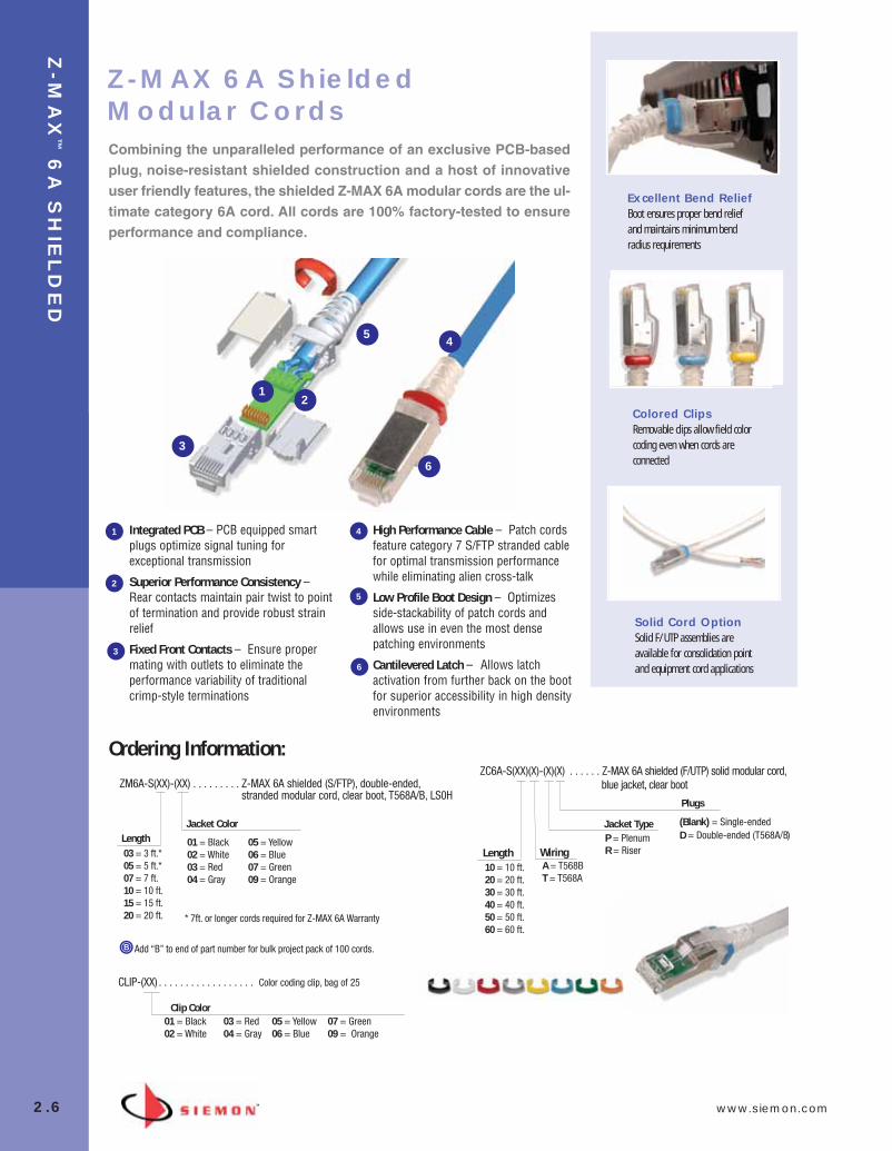
ZM6A-S(XX)-(XX) . . . . . . . . . Z-MAX 6A shielded (S/FTP), double-ended,stranded modular cord, clear boot, T568A/B, LS0H
Add “B” to end of part number for bulk project pack of 100 cords.
Integrated PCB – PCB equipped smartplugs optimize signal tuning forexceptional transmission
Superior Performance Consistency –Rear contacts maintain pair twist to pointof termination and provide robust strainrelief
Fixed Front Contacts – Ensure propermating with outlets to eliminate theperformance variability of traditionalcrimp-style terminations
High Performance Cable – Patch cordsfeature category 7 S/FTP stranded cablefor optimal transmission performancewhile eliminating alien cross-talk
Low Profile Boot Design – Optimizesside-stackability of patch cords andallows use in even the most densepatching environments
Cantilevered Latch – Allows latchactivation from further back on the bootfor superior accessibility in high densityenvironments
Jacket Color
01 = Black02 = White03 = Red04 = Gray
05 = Yellow06 = Blue07 = Green09 = Orange
Length03 = 3 ft.*05 = 5 ft.*07 = 7 ft.10 = 10 ft.15 = 15 ft.20 = 20 ft.
ZC6A-S(XX)(X)-(X)(X) . . . . . . Z-MAX 6A shielded (F/UTP) solid modular cord,
Plugs
Length10 = 10 ft.20 = 20 ft.30 = 30 ft.40 = 40 ft.50 = 50 ft.60 = 60 ft.
WiringA = T568BT = T568A
Jacket TypeP = PlenumR = Riser
CLIP-(XX) . . . . . . . . . . . . . . . . . . Color coding clip, bag of 25
Clip Color01 = Black02 = White
03 = Red04 = Gray
05 = Yellow06 = Blue
07 = Green09 = Orange
Ordering Information:
Z-MAX 6A ShieldedModular Cords
(Blank) = Single-endedD = Double-ended (T568A/B)
12
3
5 4
6
1
52
3
4
6
Combining the unparalleled performance of an exclusive PCB-basedplug, noise-resistant shielded construction and a host of innovativeuser friendly features, the shielded Z-MAX 6A modular cords are the ul-timate category 6A cord. All cords are 100% factory-tested to ensureperformance and compliance.
blue jacket, clear boot
* 7ft. or longer cords required for Z-MAX 6A Warranty
Excellent Bend ReliefBoot ensures proper bend reliefand maintains minimum bendradius requirements
Colored ClipsRemovable clips allow field colorcoding even when cords areconnected
Solid Cord OptionSolid F/UTP assemblies areavailable for consolidation pointand equipment cord applications
02_ZMax.qxd:02_ZMAX 2/12/10 3:19 PM Page 7
www.siemon.com
CA
TE
GO
RY
6A
SH
IEL
DE
D B
LA
DE
PA
TC
H™
2.7
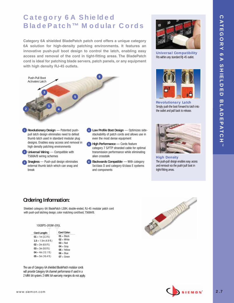
Push-Pull Boot Activates Latch
Universal CompatibilityFits within any standard RJ-45 outlet.
Revolutionary LatchSimply push the boot forward to latch intothe outlet and pull back to release.
High DensityThe push-pull design enables easy accessand removal via the push/pull boot in tight-fitting areas.
Category 6A Shielded BladePatch™ Modular Cords
Category 6A shielded BladePatch patch cord offers a unique category6A solution for high-density patching environments. It features aninnovative push-pull boot design to control the latch, enabling easyaccess and removal of the cord in tight-fitting areas. The BladePatchcord is ideal for patching blade servers, patch panels, or any equipmentwith high density RJ-45 outlets.
Revolutionary Design — Patented push-pull latch design eliminates need to defeatthumb latch used in standard modular plugdesigns. Enables easy access and removal inhigh density patching environments
Universal Wiring — Compatible withT568A/B wiring schemes
Snagless — Push-pull design eliminatesexternal thumb latch which can snag andbreak
Low Profile Boot Design — Optimizes side-stackability of patch cords and allows use ineven the most dense equipment
High Performance — Cords featurecategory 7 S/FTP stranded cable for optimaltransmission performance while eliminatingalien crosstalk
Backwards Compatible — With category5e/class D and category 6/class E systemsand components
1
2
3
4
5
6
Shielded category 6A BladePatch LS0H, double-ended, RJ-45 modular patch cordwith push-pull latching design, color matching cord/boot, T568A/B.
Cord Length:01 = 1m (3.3 ft.) 1.5 = 1.5m (4.9 ft.)02 = 2m (6.6 ft.)03 = 3m (9.8 ft.) 04 = 4m (13.1 ft.)05 = 5m (16.4 ft.)
01 = Black 02 = White03 = Red04 = Gray 05 = Yellow 06 = Blue 07 = Green
Cord Color:
The use of Category 6A shielded BladePatch modular cordswill provide Category 6A channel performance if used in a Z-MAX 6A system. Z-MAX 6A warranty margins do not apply.
Ordering Information:
10GBPS-(XX)M-(XX)L
12
3
4
5
6
02_ZMax.qxd:02_ZMAX 2/12/10 3:19 PM Page 8
Z-M
AX
™6
A S
HIE
LD
ED
2.8 www.siemon.com
Ordering Information:
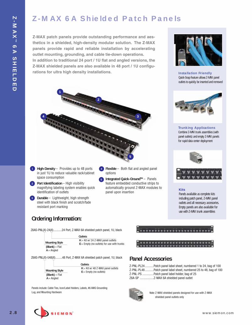
Z-MAX patch panels provide outstanding performance and aes-thetics in a shielded, high-density modular solution. The Z-MAXpanels provide rapid and reliable installation by accelerating outlet mounting, grounding, and cable tie-down operations. In addition to traditional 24 port / 1U flat and angled versions, theZ-MAX shielded panels are also available in 48 port / 1U configu-rations for ultra high density installations.
High-Density – Provides up to 48 portsin just 1U to reduce valuable rack/cabinetspace consumption
Port Identification – High visibilitymagnifying labeling system enables quickidentification of outlets
Durable – Lightweight, high strengthsteel with black finish and scratch/faderesistant port marking
Flexible – Both flat and angled paneloptions
Integrated Quick-GroundTM – Panelsfeature embedded conductive strips toautomatically ground Z-MAX modules topanel upon insertion
Z6AS-PNL(X)-24(X)...........24 Port, Z-MAX 6A shielded patch panel, 1U, black
OutletsK = Kit w/ 24 Z-MAX panel outletsE = Empty (no outlets) for use with trunksMounting Style
(Blank) = FlatA = Angled
Z6AS-PNL(X)-U48(X).........48 Port, Z-MAX 6A shielded patch panel, 1U, black
OutletsK = Kit w/ 48 Z-MAX panel outletsE = Empty (no outlets)Mounting Style
(Blank) = FlatA = Angled
Z-PNL-PL24...........Patch panel label sheet, numbered 1 to 24, bag of 100Z-PNL-PL48...........Patch panel label sheet, numbered 25 to 48, bag of 100Z-PNL-PS ..............Patch panel label holder, bag of 25Z6A-SP .................Z-MAX 6A shielded panel outlet
Panel Accessories
1
1
2
3
4
5
2
34
5
Note: Z-MAX shielded panels designed for use with Z-MAXshielded panel outlets only
Z-MAX 6A Shielded Patch Panels
Panels include: Cable Ties, Icon/Label Holders, Labels, #6 AWG GroundingLug, and Mounting Hardware
Installation FriendlyQuick-Snap feature allows Z-MAX paneloutlets to quickly be inserted and removed
Trunking ApplicationsCombine Z-MAX trunk assemblies (withpanel outlets) and empty Z-MAX panelsfor rapid data center deployment
KitsPanels available as complete kitsincluding patch panel, Z-MAX paneloutlets and all necessary accessories.Empty panels are also available foruse with Z-MAX trunk assemblies
02_ZMax.qxd:02_ZMAX 2/12/10 3:19 PM Page 9
www.siemon.com
Z-M
AX
™6
A S
HIE
LD
ED
2.9
Ordering Information:
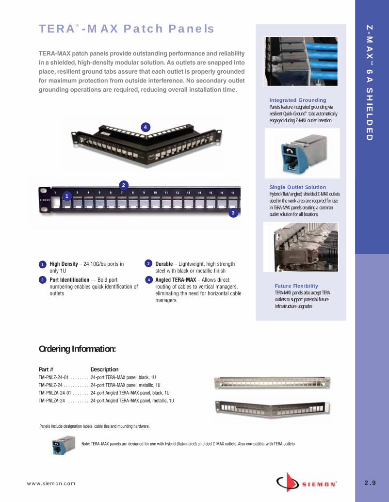
Part # DescriptionTM-PNLZ-24-01 . . . . . . . . .24-port TERA-MAX panel, black, 1U
TM-PNLZ-24 . . . . . . . . . . . .24-port TERA-MAX panel, metallic, 1U
TM-PNLZA-24-01 . . . . . . . .24-port Angled TERA-MAX panel, black, 1U
TM-PNLZA-24 . . . . . . . . . .24-port Angled TERA-MAX panel, metallic, 1U
Panels include designation labels, cable ties and mounting hardware.
TERA® -MAX Patch Panels
TERA-MAX patch panels provide outstanding performance and reliabilityin a shielded, high-density modular solution. As outlets are snapped intoplace, resilient ground tabs assure that each outlet is properly groundedfor maximum protection from outside interference. No secondary outlet grounding operations are required, reducing overall installation time.
High Density – 24 10G/bs ports in only 1U
Port Identification — Bold portnumbering enables quick identification ofoutlets
Durable – Lightweight, high strengthsteel with black or metallic finish
Angled TERA-MAX – Allows directrouting of cables to vertical managers,eliminating the need for horizontal cablemanagers
1
1
2
3
4
2
3
4
Note: TERA-MAX panels are designed for use with hybrid (flat/angled) shielded Z-MAX outlets. Also compatible with TERA outlets
Integrated GroundingPanels feature integrated grounding viaresilient Quick-Ground™ tabs automaticallyengaged during Z-MAX outlet insertion.
Single Outlet SolutionHybrid (flat/angled) shielded Z-MAX outletsused in the work area are required for usein TERA-MAX panels creating a commonoutlet solution for all locations
Future FlexibilityTERA-MAX panels also accept TERAoutlets to support potential futureinfrastructure upgrades
02_ZMax.qxd:02_ZMAX 2/12/10 3:19 PM Page 10
Z-M
AX
™6
A S
HIE
LD
ED
2.10 www.siemon.com
1
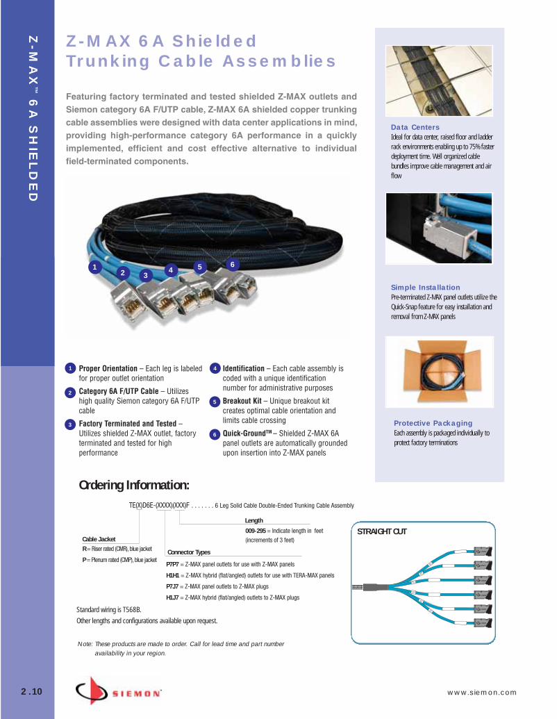
Z-MAX 6A ShieldedTrunking Cable Assemblies
Featuring factory terminated and tested shielded Z-MAX outlets andSiemon category 6A F/UTP cable, Z-MAX 6A shielded copper trunkingcable assemblies were designed with data center applications in mind,providing high-performance category 6A performance in a quickly implemented, efficient and cost effective alternative to individual field-terminated components.
Proper Orientation – Each leg is labeledfor proper outlet orientation
Category 6A F/UTP Cable – Utilizeshigh quality Siemon category 6A F/UTPcable
Factory Terminated and Tested –Utilizes shielded Z-MAX outlet, factoryterminated and tested for highperformance
Identification – Each cable assembly iscoded with a unique identificationnumber for administrative purposes
Breakout Kit – Unique breakout kitcreates optimal cable orientation andlimits cable crossing
Quick-GroundTM – Shielded Z-MAX 6Apanel outlets are automatically groundedupon insertion into Z-MAX panels
TE(X)D6E-(XXXX)(XXX)F . . . . . . . 6 Leg Solid Cable Double-Ended Trunking Cable Assembly
STRAIGHT CUT
Note: These products are made to order. Call for lead time and part numberavailability in your region.
R = Riser rated (CMR), blue jacket
P = Plenum rated (CMP), blue jacket
Standard wiring is T568B.
Other lengths and configurations available upon request.
Length
009-295 = Indicate length in feet(increments of 3 feet)Cable Jacket
Ordering Information:
P7P7 = Z-MAX panel outlets for use with Z-MAX panels
H1H1 = Z-MAX hybrid (flat/angled) outlets for use with TERA-MAX panels
P7J7 = Z-MAX panel outlets to Z-MAX plugs
H1J7 = Z-MAX hybrid (flat/angled) outlets to Z-MAX plugs
Connector Types
1
1
2
3
4
5
6
2 34 5 6
Data CentersIdeal for data center, raised floor and ladderrack environments enabling up to 75% fasterdeployment time. Well organized cablebundles improve cable management and airflow
Simple InstallationPre-terminated Z-MAX panel outlets utilize theQuick-Snap feature for easy installation andremoval from Z-MAX panels
Protective PackagingEach assembly is packaged individually toprotect factory terminations
02_ZMax.qxd:02_ZMAX 2/12/10 3:19 PM Page 11
www.siemon.com
Z-M
AX
™6
A S
HIE
LD
ED
2.11
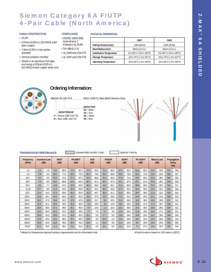
Siemon Category 6A F/UTP 4-Pair Cable (North America)
• ISO/IEC 11801:2002, Amendment 2(Category 6A draft)
• TIA-568-B.2-10 • UL CMR and CSA FT4• UL CMP and CSA FT6
CMP CMR
Pulling Tension (max) 110N (25 lbf) 110N (25 lbf)
Bend Radius (min) 50mm (2.0 in.) 50mm (2.0 in.)
Installation Temperature 0 to 60°C (+32 to 140°F) 0 to 60°C (+32 to 140°F)
Storage Temperature -20 to 75°C (-4 to 167°F) -20 to 75°C (-4 to 167°F)
Operating Temperature -20 to 60°C (-4 to 140°F) -20 to 60°C (-4 to 140°F)
PHYSICAL PROPERTIES
P = Plenum (CMP, CSA FT6) R = Riser (CMR, CSA FT4)
Jacket Color02 = White04 = Grey05 = Yellow06 = Blue
Jacket Material
CABLE CONSTRUCTION• F/UTP• 0.57mm (0.023 in.) (23 AWG) solid
bare copper• 7.4mm (0.29 in.) max jacket
diameter• Central isolation member• Shield is an aluminum foil tape
enclosing a 0.51mm (0.20 in.) (24 AWG) tinned copper drain wire
COMPLIANCE
Ordering Information:
9A6(X)4-A5-(XX)-R1A . . . . . . . . 305m (1000 ft.) Reel (North America Only)
*Values for frequencies beyond industry requirements are for information only All performance based on 100 meters (328 ft.).
Frequency Insertion Loss NEXT PS NEXT ACR PSACR ACR-F PS ACR-F Return Loss Propagation(MHz) (dB) (dB) (dB) (dB) (dB) (dB) (dB) (dB) Delay
(ns)
1.0 2.0 1.8 74.3 86.0 72.3 82.3 72.3 84.2 70.3 80.5 67.8 91.0 64.8 85.0 20.0 33.0 570 5454.0 3.8 3.4 65.3 77.0 63.3 73.3 61.5 73.6 59.5 69.9 55.8 79.0 52.8 73.0 23.0 35.5 552 527
10.0 6.0 5.4 59.3 71.0 57.3 67.3 53.3 65.6 51.3 61.9 47.8 71.0 44.8 65.0 25.0 38.0 545 52016.0 7.6 6.9 56.2 68.0 54.2 64.2 48.7 61.1 46.7 57.3 43.7 67.0 40.7 61.0 25.0 35.2 543 51820.0 8.5 7.7 54.8 67.0 52.8 62.8 46.3 59.3 44.3 55.1 41.8 65.0 38.8 59.0 25.0 35.0 542 51731.25 10.7 9.9 51.9 64.0 49.9 59.9 41.2 54.1 39.2 50.0 37.9 61.0 34.9 55.0 23.6 33.1 540 51562.5 15.4 14.3 47.4 59.0 45.4 55.4 32.0 44.7 30.0 41.1 31.9 55.0 28.9 49.0 21.5 32.2 539 514
100.0 19.8 18.1 44.3 56.0 42.3 52.0 24.5 37.9 22.5 33.9 27.8 51.0 24.8 45.0 20.1 31.6 538 513200.0 29.0 27.3 39.8 52.0 37.8 47.8 10.8 24.7 8.8 20.5 21.8 45.0 18.8 39.0 18.0 29.8 537 512250.0 32.8 31.1 38.3 50.0 36.3 46.0 5.5 18.9 3.5 14.9 19.8 43.0 16.8 37.0 17.3 28.7 536 511300.0 36.4 35.0 37.1 49.0 35.1 45.0 0.7 14.0 -1.3 10.0 18.3 38.0 15.3 35.0 16.8 28.0 536 511400.0 43.0 40.0 35.3 47.0 33.3 43.0 -7.7 7.0 -9.7 3.0 15.8 36.0 12.8 33.0 15.9 27.1 536 511500.0 48.9 42.0 33.8 47.0 31.8 42.0 -15.1 5.0 -17.1 0.0 13.8 34.0 10.8 32.0 15.2 26.0 536 510550.0* 51.8 43.0 33.2 46.0 31.2 42.0 -18.6 3.0 -20.6 -1.0 13.0 33.0 10.0 31.0 14.9 26.0 536 510625.0* 55.8 44.9 32.4 46.0 30.4 41.0 -23.5 1.1 -25.5 -3.9 11.9 33.0 8.9 29.0 14.5 25.0 535 505750.0* 62.3 49.0 31.2 45.0 29.2 41.0 -31.1 -4.0 -33.1 -8.0 10.3 32.0 7.3 27.0 14.0 25.0 535 504
TRANSMISSION PERFORMANCE GUARANTEED WORST CASE SIEMON TYPICAL
02_ZMax.qxd:02_ZMAX 2/12/10 3:20 PM Page 12
Z-M
AX
™6
A S
HIE
LD
ED
2.12 www.siemon.com
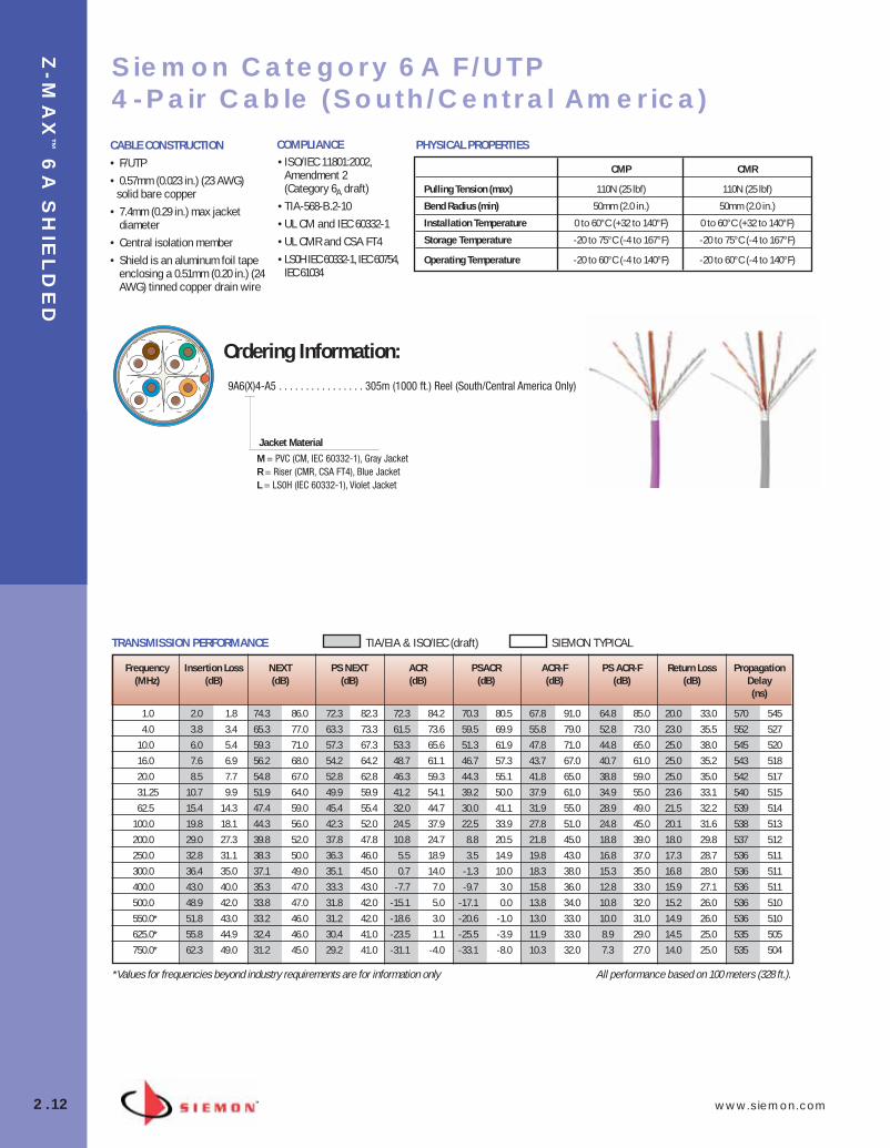
Siemon Category 6A F/UTP 4-Pair Cable (South/Central America)
• ISO/IEC 11801:2002,Amendment 2(Category 6A draft)
• TIA-568-B.2-10 • UL CM and IEC 60332-1• UL CMR and CSA FT4• LS0H IEC 60332-1, IEC 60754,
IEC 61034
CMP CMR
Pulling Tension (max) 110N (25 lbf) 110N (25 lbf)
Bend Radius (min) 50mm (2.0 in.) 50mm (2.0 in.)
Installation Temperature 0 to 60°C (+32 to 140°F) 0 to 60°C (+32 to 140°F)
Storage Temperature -20 to 75°C (-4 to 167°F) -20 to 75°C (-4 to 167°F)
Operating Temperature -20 to 60°C (-4 to 140°F) -20 to 60°C (-4 to 140°F)
PHYSICAL PROPERTIES
M = PVC (CM, IEC 60332-1), Gray Jacket R = Riser (CMR, CSA FT4), Blue Jacket L = LS0H (IEC 60332-1), Violet Jacket
Jacket Material
CABLE CONSTRUCTION• F/UTP• 0.57mm (0.023 in.) (23 AWG)
solid bare copper• 7.4mm (0.29 in.) max jacket
diameter• Central isolation member• Shield is an aluminum foil tape
enclosing a 0.51mm (0.20 in.) (24AWG) tinned copper drain wire
COMPLIANCE
Ordering Information:
9A6(X)4-A5 . . . . . . . . . . . . . . . . 305m (1000 ft.) Reel (South/Central America Only)
TRANSMISSION PERFORMANCE TIA/EIA & ISO/IEC (draft) SIEMON TYPICAL
*Values for frequencies beyond industry requirements are for information only
Frequency Insertion Loss NEXT PS NEXT ACR PSACR ACR-F PS ACR-F Return Loss Propagation(MHz) (dB) (dB) (dB) (dB) (dB) (dB) (dB) (dB) Delay
(ns)
1.0 2.0 1.8 74.3 86.0 72.3 82.3 72.3 84.2 70.3 80.5 67.8 91.0 64.8 85.0 20.0 33.0 570 5454.0 3.8 3.4 65.3 77.0 63.3 73.3 61.5 73.6 59.5 69.9 55.8 79.0 52.8 73.0 23.0 35.5 552 527
10.0 6.0 5.4 59.3 71.0 57.3 67.3 53.3 65.6 51.3 61.9 47.8 71.0 44.8 65.0 25.0 38.0 545 52016.0 7.6 6.9 56.2 68.0 54.2 64.2 48.7 61.1 46.7 57.3 43.7 67.0 40.7 61.0 25.0 35.2 543 51820.0 8.5 7.7 54.8 67.0 52.8 62.8 46.3 59.3 44.3 55.1 41.8 65.0 38.8 59.0 25.0 35.0 542 51731.25 10.7 9.9 51.9 64.0 49.9 59.9 41.2 54.1 39.2 50.0 37.9 61.0 34.9 55.0 23.6 33.1 540 51562.5 15.4 14.3 47.4 59.0 45.4 55.4 32.0 44.7 30.0 41.1 31.9 55.0 28.9 49.0 21.5 32.2 539 514
100.0 19.8 18.1 44.3 56.0 42.3 52.0 24.5 37.9 22.5 33.9 27.8 51.0 24.8 45.0 20.1 31.6 538 513200.0 29.0 27.3 39.8 52.0 37.8 47.8 10.8 24.7 8.8 20.5 21.8 45.0 18.8 39.0 18.0 29.8 537 512250.0 32.8 31.1 38.3 50.0 36.3 46.0 5.5 18.9 3.5 14.9 19.8 43.0 16.8 37.0 17.3 28.7 536 511300.0 36.4 35.0 37.1 49.0 35.1 45.0 0.7 14.0 -1.3 10.0 18.3 38.0 15.3 35.0 16.8 28.0 536 511400.0 43.0 40.0 35.3 47.0 33.3 43.0 -7.7 7.0 -9.7 3.0 15.8 36.0 12.8 33.0 15.9 27.1 536 511500.0 48.9 42.0 33.8 47.0 31.8 42.0 -15.1 5.0 -17.1 0.0 13.8 34.0 10.8 32.0 15.2 26.0 536 510550.0* 51.8 43.0 33.2 46.0 31.2 42.0 -18.6 3.0 -20.6 -1.0 13.0 33.0 10.0 31.0 14.9 26.0 536 510625.0* 55.8 44.9 32.4 46.0 30.4 41.0 -23.5 1.1 -25.5 -3.9 11.9 33.0 8.9 29.0 14.5 25.0 535 505750.0* 62.3 49.0 31.2 45.0 29.2 41.0 -31.1 -4.0 -33.1 -8.0 10.3 32.0 7.3 27.0 14.0 25.0 535 504
All performance based on 100 meters (328 ft.).
02_ZMax.qxd:02_ZMAX 2/12/10 3:20 PM Page 13
www.siemon.com
Z-M
AX
™6
A U
TP
2.13
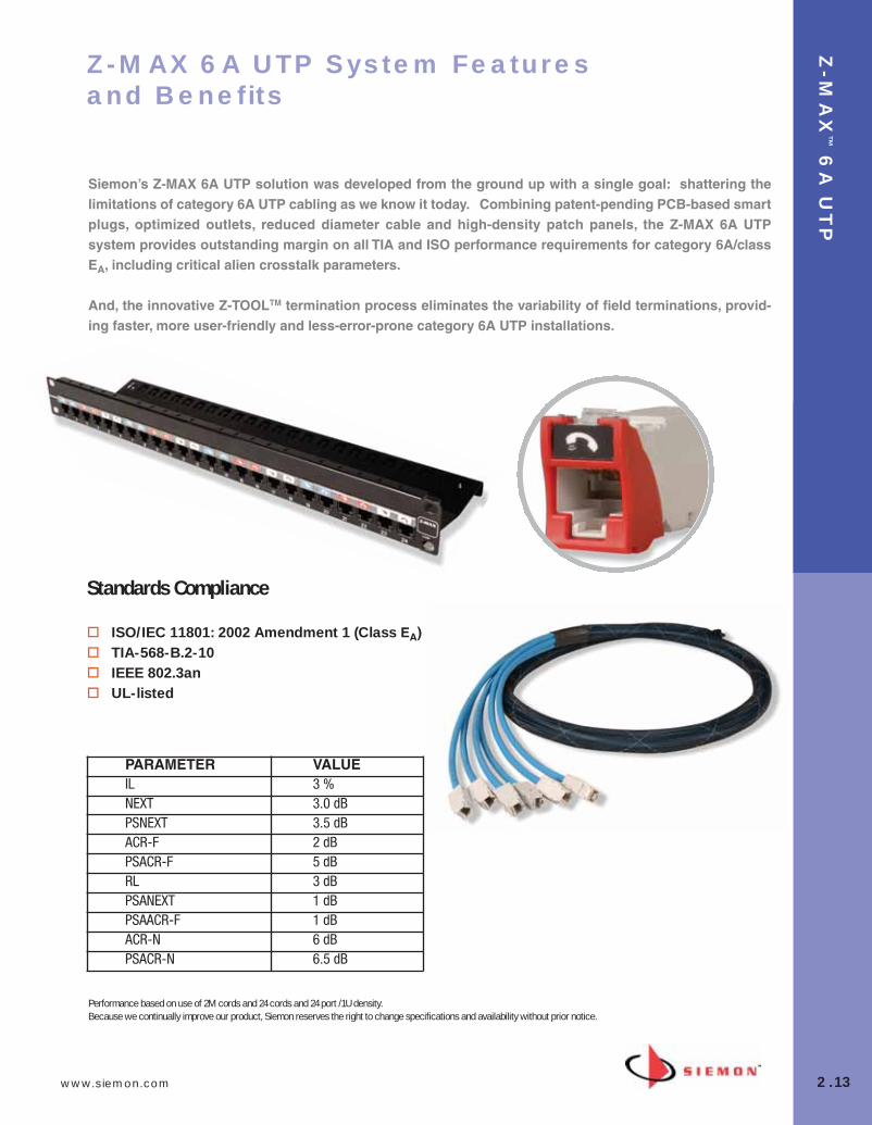
Z-MAX 6A UTP System Featuresand Benefits
Siemon’s Z-MAX 6A UTP solution was developed from the ground up with a single goal: shattering the limitations of category 6A UTP cabling as we know it today. Combining patent-pending PCB-based smartplugs, optimized outlets, reduced diameter cable and high-density patch panels, the Z-MAX 6A UTP system provides outstanding margin on all TIA and ISO performance requirements for category 6A/classEA, including critical alien crosstalk parameters.
And, the innovative Z-TOOLTM termination process eliminates the variability of field terminations, provid-ing faster, more user-friendly and less-error-prone category 6A UTP installations.
PARAMETER VALUEIL 3 %NEXT 3.0 dBPSNEXT 3.5 dBACR-F 2 dBPSACR-F 5 dBRL 3 dBPSANEXT 1 dBPSAACR-F 1 dBACR-N 6 dBPSACR-N 6.5 dB
Performance based on use of 2M cords and 24 cords and 24 port /1U density. Because we continually improve our product, Siemon reserves the right to change specifications and availability without prior notice.
Standards Compliance
� ISO/IEC 11801: 2002 Amendment 1 (Class EA)� TIA-568-B.2-10� IEEE 802.3an � UL-listed
02_ZMax.qxd:02_ZMAX 2/12/10 3:20 PM Page 14

Z-M
AX
™6
A U
TP
2.14 www.siemon.com
Fastest Termination Time – Zero-Cross™
termination module and 2-step Z-TOOL™
termination process combine for best-in-class termination time
High-Visibility Icon System – Printedicons allow designation for voice / dataapplications and also provide an additionalcolor coding option
Compact –Slim and side-stackable forhigh-density applications. Supports “pass-thru” feature to mount from the front orrear of a faceplate
Guided Termination Features – Lacingchannels guide correct conductorplacement while 2-sided color-codingprovide wiring verification before and afterlacing
Enclosed IDC Terminations – IDCterminations are fully enclosed in the outlethousing for robust protection
Robust Hinged Cable Retention – Hingedclip accommodates multiple cablediameters
1
5
2
3
4
Z-MAX 6A UTP Outlets
The category 6A UTP Z-MAX outlet offers best-in-class performance inevery critical specification, exceeding all category 6A performance requirements, including alien crosstalk. Its innovative features not only accelerate and simplify termination, but remove installation variability forconsistently high and repeatable performance - every termination, every time!
Outlet terminates UTP cable constructions with 23 – 26 AWG (0.64 – 0.51mm)solid and 26 AWG (0.48mm) stranded conductors, with up to 0.60mmdiameter conductors and up to 1.48mm diameter over insulation.
Z6A-(X)(XX) . . . . . . . . . . .UTP Z-MAX 6A outlet, T568A/B
Bezel Color
Mounting Style01 = Black02 = White03 = Red04 = Gray05 = Yellow
06 = Blue07 = Green09 = Orange20 = Ivory80 = Light Ivory
(Blank) = Hybrid Flat/Angled K = Keystone
Each Z-MAX 6A UTP hybrid flat/angled outlet includes1 printed icon set with the following color/print options.
Additional color options available.
Ordering Information:
1 - Red Data1 - Blue Data1 - Bezel Color-matching Data1 - White Blank
1 - Red Voice1 - Blue Voice1 - Bezel Color-Matching Voice1 - Bezel Color-matching Blank
2
3
5
Optimized For AlienCrosstalk IsolationDiagonal IDC alignment maximizesoutlet to outlet pair separation toarchive AXT performance in high-density, environments
Flexibility andSimplified OrderingA single hybrid outlet supports bothangled and flat mountingorientations
6
6
Note: Z-MAX 6A UTP outlets utilize 10G MAX faceplates and cannot be side-stacked in standard MAX faceplates. Z-MAX outlets utilize the Z-TOOL termination tool.
See Page 12.3.
Front
Rear
1
4
Hybrid Keystone
Add “B” to end of part number for bulk project pack of 100 modules (hybrid outlets include icons).
Add “D” to end of part number for spring door option.
02_ZMax.qxd:02_ZMAX 2/12/10 3:20 PM Page 15
www.siemon.com
CA
TE
GO
RY
6A
UT
P B
LA
DE
PA
TC
H™
2.15
Add “B” to end of part number for bulk project pack of 100 cords.
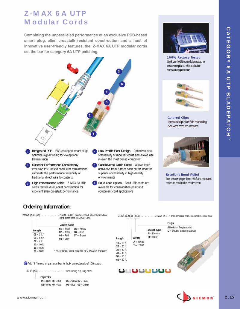
Z-MAX 6A UTP Modular Cords
Combining the unparalleled performance of an exclusive PCB-basedsmart plug, alien crosstalk resistant construction and a host of innovative user-friendly features, the Z-MAX 6A UTP modular cordsset the bar for category 6A UTP patching.
Integrated PCB – PCB equipped smart plugsoptimize signal tuning for exceptionaltransmission
Superior Performance Consistency –Precision PCB-based conductor terminationseliminate the performance variability oftraditional direct wire to contacts
High Performance Cable – Z-MAX 6A UTPcords feature dual jacket construction forexcellent alien crosstalk performance
Low Profile Boot Design – Optimizes side-stackability of modular cords and allows usein even the most dense equipment
Cantilevered Latch Guard – Allows latchactivation from further back on the boot forsuperior accessibility in high densityenvironments
Solid Cord Option – Solid UTP cords areavailable for consolidation point andequipment cord applications
CLIP-(XX) . . . . . . . . . . . . . . . . . . Color coding clip, bag of 25
ZM6A-(XX)-(XX) . . . . . . . . . . . . . Z-MAX 6A UTP, double-ended, stranded modularcord, clear boot, T568A/B, CMG
ZC6A-(XX)(X)-(X)(X) . . . . . . . . . . Z-MAX 6A UTP, solid modular cord, blue jacket, clear boot
Jacket Color01 = Black02 = White03 = Red04 = Gray
05 = Yellow06 = Blue07 = Green
Length03 = 3 ft.*05 = 5 ft.*07 = 7 ft.10 = 10 ft.15 = 15 ft.20 = 20 ft.
Plugs
(Blank) = Single-endedD = Double-ended (T568A/B)
Length
10 = 10 ft.20 = 20 ft.30 = 30 ft.40 = 40 ft.50 = 50 ft.60 = 60 ft.
WiringA = T568BT = T568A
Jacket TypeP = PlenumR = Riser
Clip Color01 = Black02 = White
03 = Red04 = Gray
05 = Yellow06 = Blue
07 = Green09 = Orange
1
1
2
3
4
5
2
3
4
5
Ordering Information:
6
6
* 7ft. or longer cords required for Z-MAX 6A Warranty
100% Factory-TestedCords are 100% transmission tested toensure compliance with applicablestandards requirements
Colored ClipsRemovable clips allow field color codingeven when cords are connected
Excellent Bend ReliefBoot ensures proper bend relief and maintainsminimum bend radius requirements
02_ZMax.qxd:02_ZMAX 2/12/10 3:20 PM Page 16
Z-M
AX
™6
A U
TP
2.16 www.siemon.com
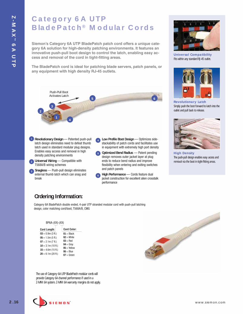
Category 6A BladePatch double ended, 4-pair UTP stranded modular cord with push-pull latchingdesign, color matching cord/boot, T568A/B, CMG
1
23
4
65
Push-Pull Boot Activates Latch
Universal CompatibilityFits within any standard RJ-45 outlet.
Revolutionary LatchSimply push the boot forward to latch into theoutlet and pull back to release.
High DensityThe push-pull design enables easy access andremoval via the boot in tight-fitting areas.
Revolutionary Design — Patented push-pulllatch design eliminates need to defeat thumblatch used in standard modular plug designs.Enables easy access and removal in highdensity patching environments
Universal Wiring — Compatible withT568A/B wiring schemes
Snagless — Push-pull design eliminatesexternal thumb latch which can snag andbreak
Low Profile Boot Design — Optimizes side-stackability of patch cords and facilitates usein equipment with extremely high port density
Optimized Bend Radius — Patent pendingdesign removes outer jacket layer at plugends to reduce bend radius and improveflexibility when entering and exiting switchesand patch panels
High Performance — Cords feature dualjacket construction for excellent alien crosstalkperformance
1
2
3
4
5
6
Category 6A UTPBladePatch® Modular Cords
Siemon’s Category 6A UTP BladePatch patch cord offers a unique cate-gory 6A solution for high-density patching environments. It features aninnovative push-pull boot design to control the latch, enabling easy ac-cess and removal of the cord in tight-fitting areas.
The BladePatch cord is ideal for patching blade servers, patch panels, orany equipment with high density RJ-45 outlets.
BP6A-(XX)-(XX)
Cord Length:03 = 0.9m (3 ft.)05 = 1.5m (5 ft.)07 = 2.1m (7 ft.)10 = 3.1m (10 ft.)15 = 4.6m (15 ft.)20 = 6.1m (20 ft.)
01 = Black 02 = White03 = Red04 = Gray 05 = Yellow 06 = Blue07 = Green
Cord Color:
Ordering Information:
The use of Category 6A UTP BladePatch modular cords willprovide Category 6A channel performance if used in a Z-MAX 6A system. Z-MAX 6A warranty margins do not apply.
02_ZMax.qxd:02_ZMAX 2/12/10 3:20 PM Page 17

www.siemon.com
Z-M
AX
™6
A U
TP
2.17
Z-MAX 6A UTP Patch Panels
Z-MAX patch panels provide outstanding 10 Gb/s performance and aesthetics in a high-density, modular UTP solution. The Z-MAX UTP panels provide rapid and reliable installation by accelerating modulemounting, and cable tie-down operations.
In addition to traditional 24-port / 1U flat and angled versions, the Z-MAX UTP panels are also available in 48-port / 1U configurations forultra high density installations.
High Density — Provides 48 ports in just1U while still meeting strict category 6AAlien Crosstalk parameter
Installation Friendly — Quick-Snap featureallows panel outlets to quickly be snappedinto place
Port Identification —High visibilitymagnifying labeling system enables quickidentification of outlets
Durable — Lightweight, high strength steelwith black finish and scratch/fade resistantport marking
Aesthetics — The Z-MAX panel provides aclean front surface to improve theinstallation appearance
Ordering Information:Z6A-PNL(X)-24(X).............24-Port, Z-MAX 6A UTP Patch Panel, 1U, Black
OutletsK = Kit w/ 24 Z-MAX Panel OutletsE = Empty (no outlets) for use with trunksMounting Style
(Blank) = FlatA = Angled
Z6A-PNL(X)-U48(X)...........48-Port, Z-MAX 6A UTP Patch Panel, 1U, Black
OutletsK = Kit w/ 48 Z-MAX Panel OutletsE = Empty (no outlets) for use with trunksMounting Style
(Blank) = FlatA = Angled
Z-PNL-PL24................Patch panel label sheet, numbered 1 to 24, bag of 100Z-PNL-PL48................Patch panel label sheet, numbered 25 to 48, bag of 100Z-PNL-PS ...................Patch panel label holder, bag of 25Z6A-P .........................Z-MAX 6A UTP panel outlet
Panel Accessories
1
1
2
3
4
5
2
3 45
Note: Z-MAX UTP panels are designed for use with Z-MAX UTP panel outlets only
Panels include: Cable Ties, Icon/Label Holders, Labels and Mounting Hardware
KitsPanels available as complete kits includingpatch panel, Z-MAX panel outlets, Z-TOOLand all necessary accessories. Empty panelsare also available for use with Z-MAX trunkassemblies
Ideal for TrunkingApplicationsCombine Z-MAX trunk assemblies (withpanel outlets) and empty Z-MAX panels forrapid data center deployment
Integrated CableManagementEnsures proper cable managementpractices for all installations, critical tocategory 6A performance
02_ZMax.qxd:02_ZMAX 2/12/10 3:20 PM Page 18

Z-M
AX
™6
A U
TP
2.18 www.siemon.com
STRAIGHT CUT
Proper Orientation — Each leg is cut andlabeled for proper module orientation
Factory Terminated and Tested —Utilizes Z-MAX 6A UTP panel outlets,factory terminated and tested for highperformance
Identification — Each cable assembly iscoded with a unique identification numberfor administrative purposes
Siemon Category 6A UTP Cable —Utilizes high quality Siemon category 6AUTP cable
Breakout Kit — Unique breakout kitcreates optimal cable orientation and limitscable crossing
Z-MAX 6A UTP Trunking Cable Assemblies
Siemon’s Z-MAX 6A UTP trunking cable assemblies provide an easily installed and cost effective alternative to individual field-terminated channels. Combining factory terminated and tested Z-MAX outletswith Siemon’s category 6A UTP cable in a high-performance modularcable assembly, Z-MAX 6A UTP trunking cable assemblies are designed to simplify the installation of category 6A systems in datacenters and other high-density high-performance environments.
TD(X)D6E-(XXXX)(XXX)F . . . . . . . 6 Leg Solid Cable Double-Ended Trunking Cable Assembly
R = Riser rated (CMR, CSA FT6), blue jacket
P = Plenum rated (CMP, CSA FT4), blue jacket
Length
009-295 = Indicate length infeet (increments of 3 feet)Cable Jacket
P0P0 = Z-MAX panel outlets for use with Z-MAX panels
H1H1 = Z-MAX hybrid flat/angled outlet
P0J0 = Z-MAX panel outlets to Z-MAX plugs
H1J0 = Z-MAX hybrid flat/angled outlet to Z-MAX plugs
Connector Types
1
1
2
3
4
5
2
3
4
5
Ordering Information:
Note: These products are made to order. Call for lead time and part number availability in your region.
Standard wiring is T568B.
Other lengths and configurations available upon request.
Data CentersIdeal for data center, raised floor and ladderrack environments enabling up to 75% fasterdeployment time. Well organized cablebundles improve cable management and airflow
Simple InstallationPre-terminated Z-MAX panel outlets utilize theQuick-Snap feature for easy installation andremoval from Z-MAX panels
Protective PackagingEach assembly is packaged individually toprotect factory terminations
02_ZMax.qxd:02_ZMAX 2/12/10 3:21 PM Page 19

www.siemon.com
Z-M
AX
™6
A U
TP
2.19
Category 6A UTP 4-Pair Cable (Americas)
PHYSICAL PROPERTIES
CMP CMR
Pulling Tension (max) 110N (25 lbf) 110N (25 lbf)
Bend Radius (min) 34mm (1.3 in.) 34mm (1.3 in.)
Installation Temperature 0 to 50°C (+32 to 122°F) 0 to 50°C (+32 to 122°F)
Storage Temperature -20 to 75°C (-4 to 167°F) -20 to 75°C (-4 to 167°F)
Operating Temperature -20 to 60°C (-14 to 140°F) -20 to 60°C (-4 to 140°F)
• UTP
• 0.58mm (0.022 in.) (23 AWG) solid bare copper
• 8.5mm (0.335 in.) CMP max jacket diameter
• Round jacket with Internal Longitudinal Striations (ILS)
CABLE CONSTRUCTION
9C6(X)4-A5-(XX)-R1A . . . . . . . . 305m (1000 ft.) Reel
P = Plenum (CMP, CSA FT6) R = Riser (CMR, CSA FT4)
Jacket Color02 = White03 = Red04 = Gray05 = Yellow06 = Blue07 = Green
Jacket Material
Ordering Information:
Please see www.siemon.com/e-catalog for more global cable options
• ISO/IEC 11801:2002, Amendment 2(Category 6A draft)
• TIA-568-B.2-10 • UL CMR and CSA FT4• UL CMP and CSA FT6
COMPLIANCE
02_ZMax.qxd:02_ZMAX 2/12/10 3:21 PM Page 20

PR
EM
IUM
6 A
ND
SY
ST
EM
6 U
TP
3.0 www.siemon.com
Siemon offers two levels of performance based on our high-performance category 6connectivity. Paired with Siemon Premium 6 UTP cable, our connectivity provides awarranted, end-to-end Premium 6 UTP cabling solution. Premium 6 exhibits margin on allparameters beyond category 6 and positive Power Sum ACR out to 250 MHz. From thetelecommunications room to the work area, the Premium 6 UTP system exceeds connectinghardware and channel performance specifications set forth for category 6/class E by the TIAand ISO/IEC.
With the use of Siemon’s Z-MAX 6 UTP outlets, Siemon’s Z-MAX Premium 6 Systemprovides margins beyond those of Premium 6, offering industry leading Category 6 Systemperformance.
Utilized with Siemon System 6 UTP cable, the Siemon category 6 connectivity family offersexceptional value in an end-to-end System 6 solution. A high-performance system meetingall category 6 requirements, System 6 is designed for installations where the additionalPremium 6 performance headroom is not required.
SECTION CONTENTS
Z-MAX® 6 UTP Modules . . . . . . . . . . . . . . . . . . . . . . . . . . . . . . . . . . . 3.1
MAX® 6 UTP Modules . . . . . . . . . . . . . . . . . . . . . . . . . . . . . . . . . . . . . 3.2
Z-MAX® 6 UTP Patch Panels . . . . . . . . . . . . . . . . . . . . . . . . . . . . . . . . 3.3
HD® 6 UTP Patch Panels . . . . . . . . . . . . . . . . . . . . . . . . . . . . . . . . . . . .3.4
12-Port HD6 Panel on S89D Bracket . . . . . . . . . . . . . . . . . . . . . . . . . .3.5
HD Panel Accessories . . . . . . . . . . . . . . . . . . . . . . . . . . . . . . . . . . . . . .3.5
MAX Patch Panels . . . . . . . . . . . . . . . . . . . . . . . . . . . . . . . . . . .3.6 – 3.7
Angled MAX Patch Panels . . . . . . . . . . . . . . . . . . . . . . . . . . . . . . . . . . .3.7
12-Port MAX Panel on S89D Bracket . . . . . . . . . . . . . . . . . . . . . . . . . .3.8
MAX Panel Accessories . . . . . . . . . . . . . . . . . . . . . . . . . . . . . . . . . . . .3.8
BladePatch® 6 UTP Modular Cords . . . . . . . . . . . . . . . . . . . . . . . . . . . .3.9
MC® 6 UTP Modular Cords . . . . . . . . . . . . . . . . . . . . . . . . . . . . . . . . .3.10
IC 6 Solid Single-Ended Modular Cords . . . . . . . . . . . . . . . . . . . . . . .3.11
S210® to MC Cable Assemblies . . . . . . . . . . . . . . . . . . . . . . . . . . . . .3.11
S210 Connection System . . . . . . . . . . . . . . . . . . . . . . . . . . . . . . . . . .3.12
S210 Field Termination Kits . . . . . . . . . . . . . . . . . . . . . . . . . . . . . . . .3.12
S210 Field Terminated 19 inch Panels . . . . . . . . . . . . . . . . . . . . . . . .3.13
System 6 Cross-Connect Wire . . . . . . . . . . . . . . . . . . . . . . . . . . . . . .3.13
S210 Patch Plugs . . . . . . . . . . . . . . . . . . . . . . . . . . . . . . . . . . . . . . . .3.14
S210 Cable Assemblies . . . . . . . . . . . . . . . . . . . . . . . . . . . . . . . . . . .3.14
Category 6 UTP Trunking Cable Assemblies . . . . . . . . . . . . . . . . . . . .3.15
Premium 6 UTP Cable (US) . . . . . . . . . . . . . . . . . . . . . . . . . . . . . . . . .3.16
System 6 UTP Cable (US) . . . . . . . . . . . . . . . . . . . . . . . . . . . . . . . . . .3.17
System 6 UTP Cable (International) . . . . . . . . . . . . . . . . . . . . . . . . . . .3.18
Premium 6™ and System 6® UTP
03_Premium6_UTP.qxd:ZMax_Catalog 1/4/10 11:19 AM Page 1
www.siemon.com
PR
EM
IUM
AN
D S
YS
TE
M 6
UT
P
3.1
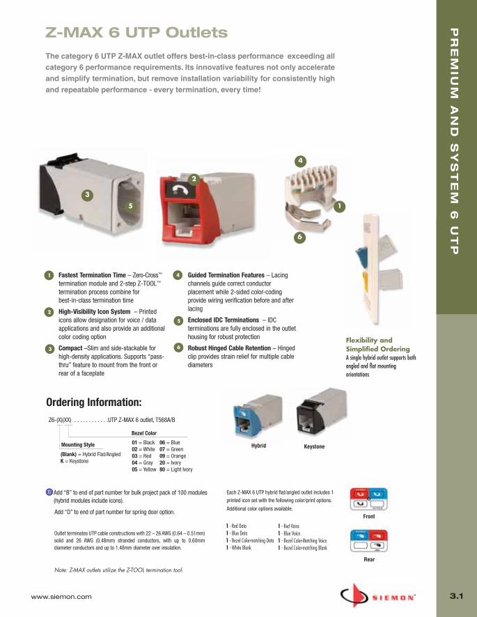
Fastest Termination Time – Zero-Cross™
termination module and 2-step Z-TOOL™
termination process combine for best-in-class termination time
High-Visibility Icon System – Printedicons allow designation for voice / dataapplications and also provide an additionalcolor coding option
Compact –Slim and side-stackable forhigh-density applications. Supports “pass-thru” feature to mount from the front orrear of a faceplate
Guided Termination Features – Lacingchannels guide correct conductorplacement while 2-sided color-codingprovide wiring verification before and afterlacing
Enclosed IDC Terminations – IDCterminations are fully enclosed in the outlethousing for robust protection
Robust Hinged Cable Retention – Hingedclip provides strain relief for multiple cablediameters
1
5
2
3
4
The category 6 UTP Z-MAX outlet offers best-in-class performance exceeding allcategory 6 performance requirements. Its innovative features not only accelerateand simplify termination, but remove installation variability for consistently highand repeatable performance - every termination, every time!
Outlet terminates UTP cable constructions with 22 – 26 AWG (0.64 – 0.51mm)solid and 26 AWG (0.48mm) stranded conductors, with up to 0.60mmdiameter conductors and up to 1.48mm diameter over insulation.
Note: Z-MAX outlets utilize the Z-TOOL termination tool.
Z6-(X)(XX) . . . . . . . . . . . .UTP Z-MAX 6 outlet, T568A/B
Bezel Color
Mounting Style 01 = Black02 = White03 = Red04 = Gray05 = Yellow
06 = Blue07 = Green09 = Orange20 = Ivory80 = Light Ivory
(Blank) = Hybrid Flat/Angled K = Keystone
Each Z-MAX 6 UTP hybrid flat/angled outlet includes 1printed icon set with the following color/print options.
Additional color options available.
Ordering Information:
1 - Red Data1 - Blue Data1 - Bezel Color-matching Data1 - White Blank
1 - Red Voice1 - Blue Voice1 - Bezel Color-Matching Voice1 - Bezel Color-matching Blank
Flexibility andSimplified OrderingA single hybrid outlet supports bothangled and flat mountingorientations
6
Hybrid Keystone
Z-MAX 6 UTP Outlets
Add “B” to end of part number for bulk project pack of 100 modules(hybrid modules include icons).
Front
Rear
Add “D” to end of part number for spring door option.
2
3
5
6
1
4
03_Premium6_UTP.qxd:ZMax_Catalog 1/4/10 11:19 AM Page 2

PR
EM
IUM
AN
D S
YS
TE
M 6
UT
P
3.2 www.siemon.com
MX6-(XX) . . . . . . . . . . . . . . . . . .
Category 6 Angled MAX module, T568A/B, rearstrain relief cap and protective color-matchingrubber door*
Use (XX) to specify color: 01 = black, 02 = white, 03 = red, 04 = gray, 05 = yellow, 06 = blue, 07 = green, 09 = orange, 20 = ivory, 25 = bright white, 80 = light ivory
Angled modules include one color-matching, one red, and one blue icon. *Door color is clear for red, yellow, blue and orange angled modules.
Flat modules include one color-matching, one red, and one blue icon.
Keystone version is designed for integration with various international mounting products and is not compatible with MAX mounting hardware.
Add “B” to end of part number for bulk project pack of 100 modules (angled and flat modules include icons).
MAX 6 UTP MODULES
1
23
4
5
6
MX6-F(XX) . . . . . . . . . . . . . . . . .
Category 6 Flat MAX module, T568A/B,rear strain relief cap
MX6-K(XX). . . . . . . . . . . . . . . . .
Category 6 Keystone MAX module,T568A/B, rear strain relief cap
Part of Siemon’s category 6 UTP end-to-end Cabling Solution,the MAX 6 module exceeds category 6 connecting hardwareperformance specifications.
It’s compact design is ideal for high density applications. Up tosix modules can be utilized in a single gang faceplate and twelvemodules in a double gang faceplate. Also, the angled MAXmodule provides a gravity feed, low-profile design for the workarea — greatly improving cable management in installationswhere front or rear clearance is at a minimum.
Flexible Installation — Install fromeither front or rear of faceplate
Easy Termination — Punch down withstandard 110 termination tools
Quick Identification — Colored Iconsprovided for port identification
Backward Compatible — Withcategory 5e/class D system components
Universal Wiring — T568A and T568Bwiring compatible
Protective Doors — Minimize exposureto dust and other contaminants (doorsnot shown)
1 4
2
3
5
6
Quick InstallationPyramid wire entry system on S310 blocksseparates paired conductors when lacingcables to simplify and reduce installationtime.
TerminationSiemon’s Palm Guard with MAX insert (p/n: PG-MX6) assists in securing moduleduring termination.
Superior PerformanceFor superior performance use MC® 6modular cords to unlock the performanceof MAX 6 modules.
MAX® 6 UTP Modules
03_Premium6_UTP.qxd:ZMax_Catalog 1/4/10 11:19 AM Page 3

www.siemon.com
PR
EM
IUM
AN
D S
YS
TE
M 6
UT
P
3.3
Z-MAX patch panels provide outstanding performance and aesthetics in a high-density, modular UTP solution. The Z-MAXUTP panels provide rapid and reliable installation by acceleratingmodule mounting, and cable tie-down operations.
In addition to traditional 24-port / 1U flat and angled versions, theZ-MAX UTP panels are also available in 48-port / 1U configurationsfor ultra high density installations.
High Density — Provides 24 or 48 ports in just 1U
Installation Friendly — Quick-Snap featureallows panel outlets to quickly be snappedinto place
Port Identification —High visibilitymagnifying labeling system enables quickidentification of outlets
Durable — Lightweight, high strength steelwith black finish and scratch/fade resistantport marking
Aesthetics — The Z-MAX panel provides aclean front surface to improve theinstallation appearance
Ordering Information:
Z-PNL-PL24................Patch panel label sheet, numbered 1 to 24, bag of 100Z-PNL-PL48................Patch panel label sheet, numbered 25 to 48, bag of 100Z-PNL-PS ...................Patch panel label holder, bag of 25Z6-P ...........................Z-MAX 6 UTP panel outlet
Panel Accessories
1
1
2
3
4
5
2
3 4 5
Note: Z-MAX UTP panels are designed for use with Z-MAXUTP panel outlets only
Z-MAX 6 UTP Patch Panels
Panels include: Cable Ties, Icon/Label Holders, Labels and Mounting Hardware
Z6-PNL(X)-24(X) ...............24 Port, Z-MAX 6 shielded patch panel, 1U, black
OutletsK -Kit w/ 24 Z-MAX panel outletsE - Empty (no outlets) for use with trunksMounting Style
(Blank) - FlatA - Angled
Z6-PNL(X)-U48(X).............48 Port, Z-MAX 6 shielded patch panel, 1U, black
OutletsK - Kit w/ 48 Z-MAX panel outletsE - Empty (no outlets)Mounting Style
(Blank) - FlatA - Angled
Ideal for Trunking ApplicationsCombine Z-MAX trunk assemblies (with paneloutlets) and empty Z-MAX panels for rapid datacenter deployment
Integrated Cable ManagementEnsures proper cable management practices forall installations
KitsPanels available as complete kits includingpatch panel, Z-MAX panel outlets, Z-TOOLand all necessary accessories. Empty panelsare also available for use with Z-MAX trunkassemblies
03_Premium6_UTP.qxd:ZMax_Catalog 1/4/10 11:19 AM Page 4
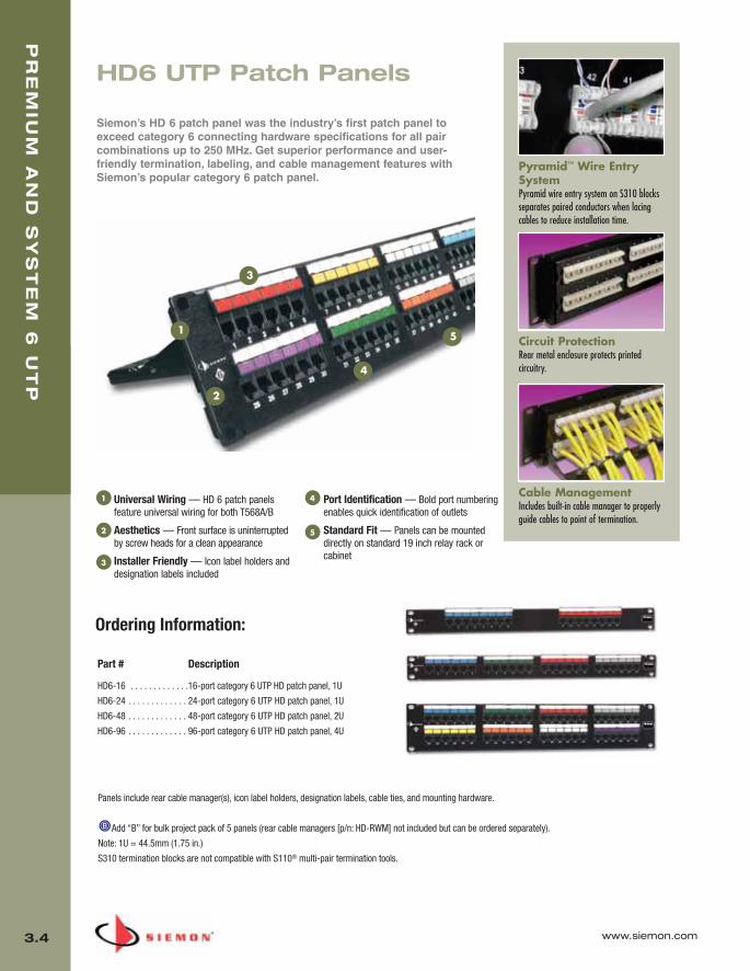
PR
EM
IUM
AN
D S
YS
TE
M 6
UT
P
3.4
Part # Description
HD6-16 . . . . . . . . . . . . .16-port category 6 UTP HD patch panel, 1U
HD6-24 . . . . . . . . . . . . . 24-port category 6 UTP HD patch panel, 1U
HD6-48 . . . . . . . . . . . . . 48-port category 6 UTP HD patch panel, 2U
HD6-96 . . . . . . . . . . . . . 96-port category 6 UTP HD patch panel, 4U
1
2
3
4
5
Panels include rear cable manager(s), icon label holders, designation labels, cable ties, and mounting hardware.
Add “B” for bulk project pack of 5 panels (rear cable managers [p/n: HD-RWM] not included but can be ordered separately).
Note: 1U = 44.5mm (1.75 in.)
S310 termination blocks are not compatible with S110® multi-pair termination tools.
HD6 UTP Patch Panels
Siemon’s HD 6 patch panel was the industry’s first patch panel toexceed category 6 connecting hardware specifications for all paircombinations up to 250 MHz. Get superior performance and user-friendly termination, labeling, and cable management features withSiemon’s popular category 6 patch panel.
Universal Wiring — HD 6 patch panelsfeature universal wiring for both T568A/B
Aesthetics — Front surface is uninterruptedby screw heads for a clean appearance
Installer Friendly — Icon label holders anddesignation labels included
Port Identification — Bold port numberingenables quick identification of outlets
Standard Fit — Panels can be mounteddirectly on standard 19 inch relay rack orcabinet
1 4
2
3
5
Cable ManagementIncludes built-in cable manager to properlyguide cables to point of termination.
Circuit ProtectionRear metal enclosure protects printedcircuitry.
Pyramid™ Wire EntrySystemPyramid wire entry system on S310 blocksseparates paired conductors when lacingcables to reduce installation time.
Ordering Information:
www.siemon.com
03_Premium6_UTP.qxd:ZMax_Catalog 1/4/10 11:20 AM Page 5

PR
EM
IUM
AN
D S
YS
TE
M 6
UT
P
3.5
12-PORT HD® 6 MOUNTED ON S89D BRACKETThe HD6-89 offers an economical solution for small applications and is ideal for retrofitting S66punch down blocks to a high performance modular design.
Part # DescriptionHD6-89D-12 . . . . . . . . . . . . . . . 12-port HD 6 panel, T568A/B, mounted on S89D bracket
height: 254.0mm (10.0 in), width: 85.9mm (3.38 in),depth: 60.2mm (2.37 in)
HD PANEL ACCESSORIES
Part # DescriptionHD-RWM . . . . . . . . . . . . . . . . . . Rear cable management bracket for HD patch panels
(not compatible with HD5-S-24
HD5-ICON6 . . . . . . . . . . . . . . . . Adhesive-backed strips in a package of 8 for color-coding and port designation for 24-, 48-, or 96-port panels (iconsnot included)
HD5-ICON6-LBL . . . . . . . . . . . . 10 sheets of labels for HD5-ICON6 for laser printing (16 labels per sheet)*
HD5-LBL-480 . . . . . . . . . . . . . . Adhesive strips for sequentially numbering panel ports 1 through 480 for 24-, 48-, or 96-port panels
HD5-LBL6-2 . . . . . . . . . . . . . . . White removable designation strips in a package of eight for 24-, 48-, or 96-port panels
HD5-LBL-480
HD5-LBL6-2
HD5-ICON6
*Visit our web site or contact our Technical Support Department for labeling software.
HD-RWM
www.siemon.com
03_Premium6_UTP.qxd:ZMax_Catalog 1/4/10 11:20 AM Page 6

PR
EM
IUM
AN
D S
YS
TE
M 6
UT
P
3.6
1
2
3 4
5
High Density Design — Accommodates up to 24 ports /1U
Aesthetics — Lightweight, high strength brushed aluminum withblack protective finish
Installer Friendly — Icon label holders and designation labelsincluded
Port Identification — Bold port numbering enables quickidentification of outlets
Standard Fit — Panels can be mounted directly on standard 19inch relay rack or cabinet
Versatility — Combines modular design with high density forultimate flexibility
1 4
2
3
5
6
MAX® Patch Panels
MAX patch panels provide a flexible, high density terminationsolution for the telecommunications room. Using the full line of Z-MAX or MAX modules (available separately), the panel can beconfigured for a variety of multimedia applications. Blankmodules can be used to reserve ports for future capacity.
Siemon’s MAX series angled patch panels route cables directly intothe vertical cable managers eliminating the need for horizontalcable management between panels.
Installation FriendlyIndividual modules snap into place fromfront or rear of panel for added installationflexibility.
Designation labelsRemovable designation labels can be laserprinted and enable proper circuitidentification for each port.
Cable ManagementRear Cable management bar included forrouting horizontal cables to terminations.
6
www.siemon.com
Eliminates HorizontalCable ManagersAngled panels route patch cords directlyinto vertical cable managers savingvaluable rack space.
03_Premium6_UTP.qxd:ZMax_Catalog 1/4/10 11:20 AM Page 7

www.siemon.com
PR
EM
IUM
AN
D S
YS
TE
M 6
UT
P
3.7
Part # Description
Panels include rear cable manager, designation labels, cable ties, and mounting hardware.
MAX Panels are not compatible with shielded MAX or Z-MAX modules. Use the TERA-MAX or Z-MAX panel.
Note: 1U= 44.5mm (1.75 in.)
MAX® PATCH PANELS
MX-PNL-16 . . . . . . . . . . 16-port MAX patch panel, 1U
Part # Description
MX-PNL-48 . . . . . . . . . . 48-port MAX patch panel, 2U
MX-PNL-24 . . . . . . . . . . 24-port MAX patch panel, 1U MX-PNL-72 . . . . . . . . . . 72-port MAX patch panel, 2U
Panels include mounting hardware. Rear cable manager not included.
Angled MAX panels are not compatible with shielded Z-MAX or MAX modules. Use the TERA-MAX or Z-MAX panel.
Angled MAX panels are not recommended for use with RS3 rack series. RS series racks with VPC vertical patching channels are recommended.
Note: 1U = 44.5mm (1.75 in.)
ANGLED MAX® PATCH PANELSSiemon’s MAX series angled patch panels route cables directly into the vertical cable managers eliminating the need forhorizontal cable management between panels.
Part # DescriptionMX-PNLA-24 . . . . . . . . . 24-port angled MAX patch panel, 1U
Part # DescriptionMX-PNLA-48 . . . . . . . . . 48-port angled MAX patch panel, 2U
03_Premium6_UTP.qxd:ZMax_Catalog 1/4/10 11:20 AM Page 8

PR
EM
IUM
AN
D S
YS
TE
M 6
UT
P
3.8 www.siemon.com
MAX PANEL ACCESSORIES
MX-PNL-LBL4* . . . . . . . . . . . . .
10 sheets of laser printable labels for 16-port MAX panels
MX-PNL-LBL6* . . . . . . . . . . . . .
10 sheets of laser printable labels for 24- and 48-port MAX panels
*Visit our web site or contact our Technical Support Department for labeling software.
12-PORT MAX® PANEL MOUNTED ON S89D BRACKET
The MAX S89D offers an economical solution for smaller applications while allowing for a range ofdifferent media using the full line of MAX modules.
Part # DescriptionMX-89D-12 . . . . . . . . . . . . . . . . 12-port MAX panel mounted on an 89D bracket
height: 254.0mm (10.0 in.), width: 85.9mm (3.38 in.), depth: 47.8mm (1.88 in.)
03_Premium6_UTP.qxd:ZMax_Catalog 1/4/10 11:20 AM Page 9

www.siemon.com
PR
EM
IUM
AN
D S
YS
TE
M 6
UT
P
3.9
1
2
3
4
5Push-Pull Boot Activates Latch
Universal CompatibilityFits within any standard RJ-45 opening.
Revolutionary LatchSimply push the boot forward to latch intothe outlet and pull back to release.
High DensityThe push-pull design enables easy accessand removal via the boot in tight-fittingareas.
Revolutionary Design — Push-pull latchdesign eliminates need to defeat thumb latchused in standard modular plug designs
Easy Access and Removal — RJ-45 patchcord with patent-pending push-pull latchdesign enables easy access and removal inhigh density patching environments
Snagless — Push-pull design eliminatesexternal thumb latch which can snag andbreak
Low Profile Boot Design — Optimizes side-stackability of patch cords and allows use ineven the most dense equipment
High Density — Ideal for high density datacenter applications and today’s high-densityblade servers
1
2
3
4
5
BladePatch® 6 UTP Modular CordsSiemon’s BladePatch 6 offers a unique category 6 solution for high-density patching environments. It features an innovative push-pullboot design to control the latch, enabling easy access and removal ofthe cord in tight-fitting areas. The BladePatch cord is ideal forpatching blade servers, patch panels, or any equipment with highdensity RJ-45 outlets.
BLADEPATCH® 6 UTPCategory 6 UTP BladePatch, double-ended, RJ-45 modular patch cordwith push-pull latching design, color matching cord/boot, T568A/B.
Cord Length:
03 = 0.9m (3 ft.)
05 = 1.5m (5 ft.)
07 = 2.1m (7 ft.)
10 = 3.1m (10 ft.)
15 = 4.6m (15 ft.)
20 = 6.1m (20 ft.)
01 = Black 02 = White03 = Red04 = Gray 05 = Yellow 06 = Blue07 = Green
Cord Color:
BP6-(XX)-(XX)
03_Premium6_UTP.qxd:ZMax_Catalog 1/4/10 11:20 AM Page 10
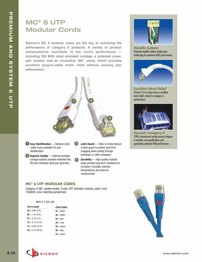
PR
EM
IUM
AN
D S
YS
TE
M 6
UT
P
3.10 www.siemon.com
Metallic IsolatorPatented metallic isolator shields pairsinside plug for optimum NEXT performance.
Excellent Bend Relief37mm (1.4 in.) boot ensures excellentbend relief, critical for category 6performance.
Exceeds Category 6100% transmission testing ensures category6 modular cord specifications andguarantees optimum field performance.
1 2
3
4
Easy Identification — Optional color-coded icons available for portidentification
Superior Quality — Internal strandedcordage isolator provides extended flexlife and maintains ideal pair geometry
Latch Guard — Slide on boots featurea latch guard to protect plug fromsnagging when pulling throughpathways or cable managers
Durability — High quality modularplugs provide long-term resistance tocorrosion, humidity, extremetemperatures and airbornecontaminants
1
4
2
3
MC® 6 UTPModular Cords
Siemon’s MC 6 modular cords are the key to unlocking theperformance of category 6 products. A variety of productenhancements contribute to the cord’s performance —including 250 MHz rated stranded cordage, a patented cross-pair isolator and an innovative 360° crimp, which providesexcellent plug-to-cable strain relief without causing pairdeformation.
MC® 6 UTP MODULAR CORDSCategory 6 MC, double-ended, 4-pair UTP stranded modular patch cord,T568A/B, color matching jacket/boot.
Cord Color:Cord Length:
03 = 0.9m (3 ft.)
05 = 1.5m (5 ft.)
07 = 2.1m (7 ft.)
10 = 3.1m (10 ft.)
15 = 4.6m (15 ft.)
20 = 6.1m (20 ft.)
01 = Black
02 = White
03 = Red
04 = Gray
05 = Yellow
06 = Blue
07 = Green
MC6-8-T-(XX)-(XX)
03_Premium6_UTP.qxd:ZMax_Catalog 1/4/10 11:20 AM Page 11

www.siemon.com
PR
EM
IUM
AN
D S
YS
TE
M 6
UT
P
3.11
IC 6 SOLID SINGLE-ENDED MODULAR CORDSSiemon’s category 6 IC solid single-ended modular cords are designed for use in category 6 applications requiring a consolidation point (CP)or cross-connect (as an equipment cord). The cords are 100% factory transmission tested to 250 MHz and feature the same plug constructionused in Siemon’s stranded category 6 modular cords. These cords are available in CMP and CMR versions and are single-ended for directtermination.
PREMIUM 6 IC MODULAR CORDS Part # DescriptionIC6E-8A-(XX)-B(XX)R . . . . . . . . . Premium 6 IC, single-ended, non-plenum, 4-pair UTP solid modular cord,
blue jacket with colored boot, T568B, CMR
IC6E-8T-(XX)-B(XX)R . . . . . . . . . Premium 6 IC, single-ended, non-plenum, 4-pair UTP solid modular cord, blue jacket with colored boot, T568A, CMR
IC6E-8A-(XX)-B(XX)P . . . . . . . . . Premium 6 IC, single-ended, plenum, 4-pair UTP solid modular cord, blue plenum jacket with colored boot T568B, CMP
IC6E-8T-(XX)-B(XX)P . . . . . . . . . Premium 6 IC, single-ended, plenum, 4-pair UTP solid modular cord, blue plenum jacket with colored boot, T568A, CMP
SYSTEM 6 IC MODULAR CORDS Part # DescriptionIC6-8A-(XX)-B(XX)R . . . . . . . . . . System 6 IC, single-ended, non-plenum, 4-pair UTP solid modular cord,
blue jacket with colored boot, T568B, CMR
IC6-8T-(XX)-B(XX)R . . . . . . . . . . System 6 IC, single-ended, non-plenum, 4-pair UTP solid modular cord, blue jacket with colored boot, T568A, CMR
IC6-8A-(XX)-B(XX)P . . . . . . . . . System 6 IC, single-ended, plenum, 4-pair UTP solid modular cord, blue plenum jacket with colored boot T568B, CMP
IC6-8T-(XX)-B(XX)P . . . . . . . . . . System 6 IC, single-ended, plenum, 4-pair UTP solid modular cord, blue plenum jacket with colored boot, T568A, CMP
Use 1st (XX) to specify cord length: 10 = 3.1m (10 ft.), 20 = 6.1m (20 ft.), 30 = 9.1m (30 ft.), 40 = 12.2m (40 ft.), 50 = 15.2m (50 ft.), 60 = 18.3m (60 ft.)
Use 2nd (XX) to specify color of boot: 01 = black, 02 = white, 03 = red, 04 = gray, 05 = yellow, 06 = blue, 07 = green
Use 1st (XX) to specify cord length: 03 = 0.9m (3 ft.), 05 = 1.5m (5 ft.), 07 = 2.1m (7 ft.), 10 = 3.1m (10 ft.), 15 = 4.6m (15 ft.), 20 = 6.1m (20 ft.)
Use 2nd (XX) to specify color: 01 = black, 02 = white, 03 = red, 04 = gray, 05 = yellow, 06 = blue, 07 = green
S210® TO MC CABLE ASSEMBLIESThe S210 to modular cable assemblies combine Siemon’s high performing plugs for patching network equipment to S210 connecting blocks or providing testaccess to S210 termination fields. The combination of plugs, high performance cable and 100% factory transmission testing ensures performance iscompatible with category 6 channel specifications.
Part # DescriptionS210P4A4-(XX)-(XX) . . . . . . . . . 4-pair, S210P4 to MC 6 stranded cable assembly,
color matching jacket/boot, T568B, CMG
S210P4T4-(XX)-(XX) . . . . . . . . . 4-pair, S210P4 to MC 6 stranded cable assembly, color matching jacket/boot, T568A, CMG
S210P2E2-(XX)-B(XX) . . . . . . . . 2-pair, S210P2 to MC 6 stranded cable assembly, white jacket with colored boot, 10/100BASE-T, CMG
03_Premium6_UTP.qxd:ZMax_Catalog 1/4/10 11:20 AM Page 12

PR
EM
IUM
AN
D S
YS
TE
M 6
UT
P
3.12 www.siemon.com
Colored Labels — Designation strip withinterchangeable colored labels can bemounted between each row ofconnecting blocks
Stand-off Legs — Patented stand-offlegs may be detached from the blockbefore, during, or after installation on 64-pair version
Compatibility — Utilizes same wiringbase footprint as standard S110®
products to be fully compatible withexisting S110 mounting and cablemanagement solutions
Easy Termination — Utilizes sametermination practices as existing S110product and is compatible with all single-position S110 termination tools
1
4
2
3
Internal CrosstalkBarriersProvide superior NEXT performance (13 dB NEXT margin over category 6specifications) via 360° pair isolation.
Pyramid™ Wire EntrySystemSeparates paired conductors when lacingcables to simplify and reduce installationtime.
Cable Access OpeningsAllow cables to be routed through the rearof the block directly to the point oftermination.
S210® Connection System
The Siemon S210 offers the best connecting block performance inthe telecommunications industry. Its NEXT performance is soexceptional that it is essentially transparent when used as aconsolidation point in a category 6 channel.
1
2
34
S210® Field Termination Kits Complete S210 installation kits include S210 wiring blocks with detachable legs*, S210 connecting blocks,and label holders with white designation labels.
Part # DescriptionS210AB2-64FT . . . . . . . . . . . . . 64-pair, S210 field termination kit
height: 91.4mm (3.60 in.), width: 272mm (10.71 in.), depth: 82.8mm (3.26 in.)
S210AB2-128FT . . . . . . . . . . . . 128-pair, S210 field termination kitheight: 182.9mm (7.20 in.), width: 272mm (10.71 in.), depth: 82.8mm (3.26 in.)
S210AB2-192FT . . . . . . . . . . . . 192-pair, S210 field termination kitheight: 275mm (10.81 in.),width: 272mm (10.71 in.), depth: 82.8mm (3.26 in.)
*Legs detachable on 64-pair version only.
03_Premium6_UTP.qxd:ZMax_Catalog 1/4/10 11:20 AM Page 13

www.siemon.com
PR
EM
IUM
AN
D S
YS
TE
M 6
UT
P
3.13
SYSTEM 6 CROSS-CONNECT WIRESiemon’s System 6 cross-connect is ideal for cross-connect applications up to 5 meters. Itcan be used for System 6 installations using S210® wiring blocks.
Part # DescriptionCJ6-W4-1000 . . . . . . . . . . . . . . System 6, 4-pair, 24 AWG (0.05mm), solid cross-
connect wire, pair colorsblue/orange/green/brown, 305mm (1000 ft.) spool
COMPLIANCE
• ISO/IEC 11801:2002 2nd Edition (category 6)
• TIA-568-C.2 (Category 6)
• IEC 61156-5:2002 (Category 6)
CABLE CONSTRUCTION
• 0.5mm (0.02 in.) 24 AWG bare copper conductors
• 1.02mm (0.04 in.) insulation diameter nominal
S210® FIELD TERMINATED 19 INCH PANELSS210 panels allow wiring blocks to be mounted directly to a 19 inch rack or cabinet. Each panel includesthe appropriate quantity of S210 connecting blocks, mounting hardware and label holders with whitedesignation labels. Patented openings between rows allow horizontal cables to be routed from behind thepanel and enter the block from the rear, helping to maintain cable jacket and twist up to the point oftermination.
Part # DescriptionS210DB2-64RFT . . . . . . . . . . . . 64-pair, 19 inch S210 field termination kit, 1U
S210DB2-128RFT . . . . . . . . . . . 128-pair, 19 inch S210 field termination kit, 2U
S210DB2-192RFT . . . . . . . . . . . 192-pair, 19 inch S210 field termination kit, 3U
Note: 1U = 44.5mm (1.75 in.)
03_Premium6_UTP.qxd:ZMax_Catalog 1/4/10 11:20 AM Page 14

PR
EM
IUM
AN
D S
YS
TE
M 6
UT
P
3.14 www.siemon.com
S210® Patch Plugs
The S210 patch plug utilizes internal pair isolation, pair-to-paircompensation and layered contacts to improve cross-talkperformance so that the mated plug and connecting block far exceedcategory 6 connecting hardware transmission requirements. The clearhousing keeps the conductor colors/positions visible to aid matchingtermination positions on the other end.
4
5
Proper Orientation — Directional arrowprovided to assist in proper insertionorientation
Tapered Lacing — Enable easy fieldtermination
Ergonomic Handle — Aids insertion andremoval of patch plug
Clear Housing — Durable, flame-retardant, clear thermoplastic housingkeeps conductors visible during and aftertermination
Polarization — Each plug housingincludes polarization features to ensureproper orientation of the plug whenconnecting to the S210 block
1 4
2
3
5
S210 patch plugs can be field-terminated to 23 – 26 AWG (0.40mm – 0.51mm) solid or 7-strand twisted-pair cable.
S210P2 . . . . . . . . . . . . . . . . . .
2-pair, field-terminated, S210 patch plug
S210P4 . . . . . . . . . . . . . . . . . .
4-pair, field-terminated, S210 patch plug
S210P1 . . . . . . . . . . . . . . . . . .
1-pair, field-terminated, S210 patch plug
Use (XX) to specify cord length: 03 = 0.9m (3 ft.), 05 = 1.5m (5 ft.), 07 = 2.1m (7 ft.), 10 = 3.1m (10 ft.), 15 = 4.6m (15 ft.), 20 = 6.1m (20 ft.)
Custom lengths available upon request. Contact our Customer Service Department for more information.
S210 CABLE ASSEMBLIESThe S210 cable assemblies utilize Siemon’s S210P4 patch plugs for easy and reliable connections between S210 termination fields. These assemblies use highperformance stranded cable which exceeds category 6 specifications and are 100% factory transmission tested to ensure optimum category 6 channelperformance. Colored icons are available for color-coding S210 plugs.
Part # DescriptionS210P4-P4-(XX) . . . . . . . . . . . . 4-pair, double-ended, S210 stranded cable assembly, white jacket
S210P2-P2-(XX) . . . . . . . . . . . . 2-pair, double-ended, S210 stranded cable assembly, white jacket
S210P1-P1-(XX) . . . . . . . . . . . . 1-pair, double-ended, S210 stranded cable assembly, white jacket
Field InstallableTerminates 24-26 AWG (0.40mm-0.51mm)solid or 7-strand twisted-pair cable.
NEXT PerformanceThe S210 4-pair plug provides unparalleledperformance, with 6.7 dB NEXT (typical)and 2.2 dB NEXT (worst case) at 250 MHz.
Easy TerminationSimply snap the base and cover together tomass terminate all conductors.
Limit
Typical
Worst Case
Margin at 250 MHzWorst Case 2.2 dBTypical 6.7 dB
1 10 100 250
-40
-50
-60
-70
-80
-90
-100
-110
-120
Frequency (MHz)
(dB)
Technical Tip!S210 to MC® 6 cable assemblies can be configured in the field. Siemon MC 6 modular cords can bepurchased and cut in half. The cut end of the cord can then be field terminated to the S210P patchplug while the factory terminated and tested modular plug end remains undisturbed.
1
3
2
03_Premium6_UTP.qxd:ZMax_Catalog 1/4/10 11:20 AM Page 15

www.siemon.com
PR
EM
IUM
AN
D S
YS
TE
M 6
UT
P
3.15
STRAIGHT CUT
Data CentersIdeal for data center, raised floor and ladderrack environments enabling up to 75% fasterdeployment time. Well organized cablebundles improve cable management and airflow.
Straight CutTypical installation utilizing Straight Cutensures each cable is terminated at theproper length and allows left, right orcenter exit.
Protective PackagingEach assembly is packaged individually toprotect factory terminations.
Proper Orientation — Each leg is labeledfor proper module orientation
Siemon Cable — Utilizes high qualitySiemon cable
Factory Terminated and Tested —Utilizes Z-MAX panel outlets or flat UTP MAXmodules, factory terminated and tested forhigh performance
Identification — Each cable assembly iscoded with a unique identification number foradministrative purposes
Breakout Kit — Unique breakout kit createsoptimal cable orientation and limits cablecrossing
1
2
3
4
5
Category 6 UTP TrunkingCable Assemblies
MAX PREMIUM 6 DOUBLE-ENDED TRUNKING CABLE ASSEMBLIESPart # DescriptionTPRD6E-A1A1(XXX)F . . . . . . . . . 6 Leg Solid Cable Trunking Cable Assembly, blue jacket, CMR
TPPD6E-A1A1(XXX)F . . . . . . . . . 6 Leg Solid Cable Trunking Cable Assembly, blue jacket, CMP
MAX SYSTEM 6 DOUBLE-ENDED TRUNKING CABLE ASSEMBLIESPart # DescriptionTCRD6E-A1A1(XXX)F . . . . . . . . . 6 Leg Solid Cable Trunking Cable Assembly, blue jacket, CMR
TCPD6E-A1A1(XXX)F . . . . . . . . . 6 Leg Solid Cable Trunking Cable Assembly, blue jacket, CMP
Z-MAX™ PREMIUM 6 DOUBLE-ENDED TRUNKING CABLE ASSEMBLIES W/PANEL OUTLETS Part # DescriptionTPRD6E-POPO(XXX)F. . . . . . . . . 6 Leg Solid Cable Trunking Cable Assembly, blue jacket, CMR
TPD6E-POPO(XXX)F . . . . . . . . . . 6 Leg Solid Cable Trunking Cable Assembly, blue jacket, CMP
Z-MAX™ SYSTEM 6 DOUBLE-ENDED TRUNKING CABLE ASSEMBLIES W/PANEL OUTLETSPart # DescriptionTCRD6E-POPO(XXX)F. . . . . . . . . 6 Leg Solid Cable Trunking Cable Assembly, blue jacket, CMR
TCPD6E-POPO(XXX)F. . . . . . . . . 6 Leg Solid Cable Trunking Cable Assembly, blue jacket, CMP
1
2
3
4
5
Siemon’s category 6 UTP copper trunkingcable assemblies provide an efficient andcost effective alternative to individual field-terminated components. Combiningfactory terminated and tested UTP Z-MAXor MAX® modules with Siemon Premiumor System 6 cable, Siemon coppertrunking cable assemblies were designedwith data center applications in mind. Inaddition to providing simple andaesthetically pleasing cable management,standard configurations also help maintainconsistent cable layout and facilitateefficient moves, adds and changes. themodular design and reduced scrap oftrunk assemblies make them the most“Green” method for category 6 cabling.
Use (XXX) to specify length: 009-295 ft. in increments of 3 feet
Standard wiring is T568B. Other lengths and configurations available upon request.
03_Premium6_UTP.qxd:ZMax_Catalog 1/4/10 11:20 AM Page 16
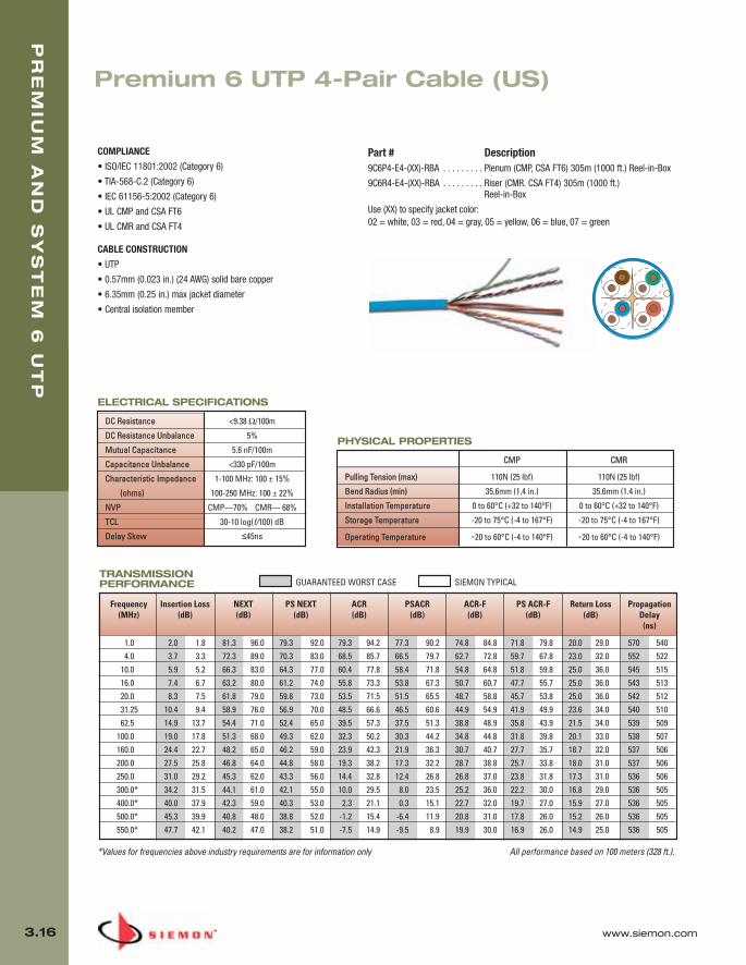
Premium 6 UTP 4-Pair Cable (US)
PR
EM
IUM
AN
D S
YS
TE
M 6
UT
P
3.16 www.siemon.com
COMPLIANCE
• ISO/IEC 11801:2002 (Category 6)
• TIA-568-C.2 (Category 6)
• IEC 61156-5:2002 (Category 6)
• UL CMP and CSA FT6
• UL CMR and CSA FT4
CABLE CONSTRUCTION
• UTP
• 0.57mm (0.023 in.) (24 AWG) solid bare copper
• 6.35mm (0.25 in.) max jacket diameter
• Central isolation member
*Values for frequencies above industry requirements are for information only All performance based on 100 meters (328 ft.).
TRANSMISSIONPERFORMANCE GUARANTEED WORST CASE SIEMON TYPICAL
Part # Description9C6P4-E4-(XX)-RBA . . . . . . . . . Plenum (CMP, CSA FT6) 305m (1000 ft.) Reel-in-Box
9C6R4-E4-(XX)-RBA . . . . . . . . . Riser (CMR. CSA FT4) 305m (1000 ft.)Reel-in-Box
Use (XX) to specify jacket color:02 = white, 03 = red, 04 = gray, 05 = yellow, 06 = blue, 07 = green
CMP CMR
Pulling Tension (max) 110N (25 lbf ) 110N (25 lbf)
Bend Radius (min) 35.6mm (1.4 in.) 35.6mm (1.4 in.)
Installation Temperature 0 to 60°C (+32 to 140°F) 0 to 60°C (+32 to 140°F)
Storage Temperature -20 to 75°C (-4 to 167°F) -20 to 75°C (-4 to 167°F)
Operating Temperature -20 to 60°C (-4 to 140°F) -20 to 60°C (-4 to 140°F)
PHYSICAL PROPERTIES
Frequency Insertion Loss NEXT PS NEXT ACR PSACR ACR-F PS ACR-F Return Loss Propagation(MHz) (dB) (dB) (dB) (dB) (dB) (dB) (dB) (dB) Delay
(ns)
1.0 2.0 1.8 81.3 96.0 79.3 92.0 79.3 94.2 77.3 90.2 74.8 84.8 71.8 79.8 20.0 29.0 570 5404.0 3.7 3.3 72.3 89.0 70.3 83.0 68.5 85.7 66.5 79.7 62.7 72.8 59.7 67.8 23.0 32.0 552 522
10.0 5.9 5.2 66.3 83.0 64.3 77.0 60.4 77.8 58.4 71.8 54.8 64.8 51.8 59.8 25.0 36.0 545 51516.0 7.4 6.7 63.2 80.0 61.2 74.0 55.8 73.3 53.8 67.3 50.7 60.7 47.7 55.7 25.0 36.0 543 51320.0 8.3 7.5 61.8 79.0 59.8 73.0 53.5 71.5 51.5 65.5 48.7 58.8 45.7 53.8 25.0 36.0 542 51231.25 10.4 9.4 58.9 76.0 56.9 70.0 48.5 66.6 46.5 60.6 44.9 54.9 41.9 49.9 23.6 34.0 540 51062.5 14.9 13.7 54.4 71.0 52.4 65.0 39.5 57.3 37.5 51.3 38.8 48.9 35.8 43.9 21.5 34.0 539 509
100.0 19.0 17.8 51.3 68.0 49.3 62.0 32.3 50.2 30.3 44.2 34.8 44.8 31.8 39.8 20.1 33.0 538 507160.0 24.4 22.7 48.2 65.0 46.2 59.0 23.9 42.3 21.9 36.3 30.7 40.7 27.7 35.7 18.7 32.0 537 506200.0 27.5 25.8 46.8 64.0 44.8 58.0 19.3 38.2 17.3 32.2 28.7 38.8 25.7 33.8 18.0 31.0 537 506250.0 31.0 29.2 45.3 62.0 43.3 56.0 14.4 32.8 12.4 26.8 26.8 37.0 23.8 31.8 17.3 31.0 536 506300.0* 34.2 31.5 44.1 61.0 42.1 55.0 10.0 29.5 8.0 23.5 25.2 36.0 22.2 30.0 16.8 29.0 536 505400.0* 40.0 37.9 42.3 59.0 40.3 53.0 2.3 21.1 0.3 15.1 22.7 32.0 19.7 27.0 15.9 27.0 536 505500.0* 45.3 39.9 40.8 48.0 38.8 52.0 -1.2 15.4 -6.4 11.9 20.8 31.0 17.8 26.0 15.2 26.0 536 505550.0* 47.7 42.1 40.2 47.0 38.2 51.0 -7.5 14.9 -9.5 8.9 19.9 30.0 16.9 26.0 14.9 25.0 536 505
DC Resistance <9.38 Ω/100m
DC Resistance Unbalance 5%
Mutual Capacitance 5.6 nF/100m
Capacitance Unbalance <330 pF/100m
Characteristic Impedance 1-100 MHz: 100 ± 15%
(ohms) 100-250 MHz: 100 ± 22%
NVP CMP—70% CMR— 68%
TCL 30-10 log(f/100) dB
Delay Skew ≤45ns
ELECTRICAL SPECIFICATIONS
03_Premium6_UTP.qxd:ZMax_Catalog 1/4/10 11:21 AM Page 17

www.siemon.com
PR
EM
IUM
AN
D S
YS
TE
M 6
UT
P
3.17
COMPLIANCE
• ISO/IEC 11801:2002 (Category 6)
• TIA-568-C.2 (Category 6)
• IEC 61156-5:2002 (Category 6)
• UL CMP and CSA FT6
• UL CMR and CSA FT4
CABLE CONSTRUCTION
• UTP
• 0.54mm (0.021 in.) (23-24 AWG) solid bare copper
• 5.6mm (0.22 in.) max jacket diameter
• Central isolation member
*Values for frequencies above industry requirements are for information only All performance based on 100 meters (328 ft.).
Frequency Insertion Loss NEXT PS NEXT ACR PSACR ACR-F PS ACR-F Return Loss Propagation(MHz) (dB) (dB) (dB) (dB) (dB) (dB) (dB) (dB) Delay
(ns)
1.0 2.0 1.8 77.3 87.3 75.3 82.3 75.3 85.5 73.3 80.5 70.8 84.8 68.8 79.8 20.0 29.0 550 5454.0 3.8 3.5 68.3 78.3 66.3 73.3 64.5 74.8 62.5 69.8 58.8 72.8 56.8 67.8 23.6 32.0 532 527
10.0 5.9 5.6 62.3 72.3 60.3 67.3 56.4 66.7 54.4 61.7 50.8 64.8 48.8 59.8 26.0 38.0 525 52016.0 7.5 7.1 59.2 69.2 57.2 64.2 51.8 62.1 49.8 57.1 46.7 60.7 44.7 55.7 26.0 34.0 523 51820.0 8.4 7.9 57.8 67.8 55.8 62.8 49.4 59.9 47.4 54.9 44.8 58.8 42.8 53.8 26.0 34.0 522 51731.25 10.6 10.0 54.9 64.9 52.9 59.9 44.3 54.9 42.3 49.9 40.9 54.9 38.9 49.9 23.6 32.0 520 51562.5 15.2 14.4 50.4 60.4 48.4 55.4 35.1 46.0 33.1 41.0 34.9 48.9 32.9 43.9 21.5 32.0 519 514
100.0 19.6 18.6 47.3 57.3 45.3 52.3 27.7 38.7 25.7 33.7 30.8 44.8 28.8 39.8 20.1 32.0 518 513160.0 25.4 24.1 44.2 54.2 42.2 49.2 18.9 30.1 16.9 25.1 26.7 40.7 24.7 35.7 18.7 31.0 517 512200.0 28.7 26.8 42.8 52.8 40.8 47.8 14.1 26.0 12.1 21.0 24.8 38.8 22.8 33.8 18.0 29.0 517 512250.0 32.6 30.5 41.3 51.3 39.3 46.3 8.8 20.8 6.8 15.8 22.8 37.0 20.8 31.8 17.3 29.0 516 511300.0* 36.1 33.7 40.1 50.0 38.1 45.0 4.0 16.3 2.0 11.3 21.3 36.0 19.3 30.0 16.8 27.0 516 511400.0* 42.6 40.3 38.3 48.0 36.3 43.0 -4.3 7.7 -6.3 2.7 18.8 32.0 16.8 27.0 15.9 26.0 516 511500.0* 48.5 39.9 36.8 48.0 34.8 42.0 -11.7 8.1 -13.7 2.1 16.8 31.0 14.8 26.0 15.2 25.0 516 511550.0* 51.3 39.7 36.2 46.0 34.2 42.0 -15.1 6.3 -17.1 2.3 16.0 30.0 14.0 26.0 14.9 24.0 516 510
TRANSMISSIONPERFORMANCE GUARANTEED WORST CASE SIEMON TYPICAL
Part # Description9C6P4-E3-(XX)-RXA . . . . . . . . . Plenum (CMP, CSA FT6) 305m (1000 ft.) Reelex
9C6R4-E3-(XX)-RXA . . . . . . . . . Riser (CMR. CSA FT4) 305m (1000 ft.) Reelex
Use (XX) to specify jacket color:02 = white, 03 = red, 04 = gray, 05 = yellow, 06 = blue, 07 = green
CMP CMR
Pulling Tension (max) 110N (25 lbf) 110N (25 lbf)
Bend Radius (min) 22mm (0.9 in.) 22mm (0.9 in.)
Installation Temperature 0 to 60°C (+32 to 140°F) 0 to 60°C (+32 to 140°F)
Storage Temperature -20 to 75°C (-4 to 167°F) -20 to 75°C (-4 to 167°F)
Operating Temperature -20 to 60°C (-4 to 140°F) -20 to 60°C (-4 to 140°F)
PHYSICAL PROPERTIES
DC Resistance <9.38 Ω/100m
DC Resistance Unbalance 5%
Mutual Capacitance 5.6 nF/100m
Capacitance Unbalance <330 pF/100m
Characteristic Impedance 1-100 MHz: 100 ± 15%
(ohms) 100-550 MHz: 100 ± 22%
NVP CMP—70% CMR— 68%
TCL 30-10 log(f/100) dB
Delay Skew ≤35ns
ELECTRICAL SPECIFICATIONS
System 6 UTP 4-Pair Cable (US)
03_Premium6_UTP.qxd:ZMax_Catalog 1/4/10 11:21 AM Page 18
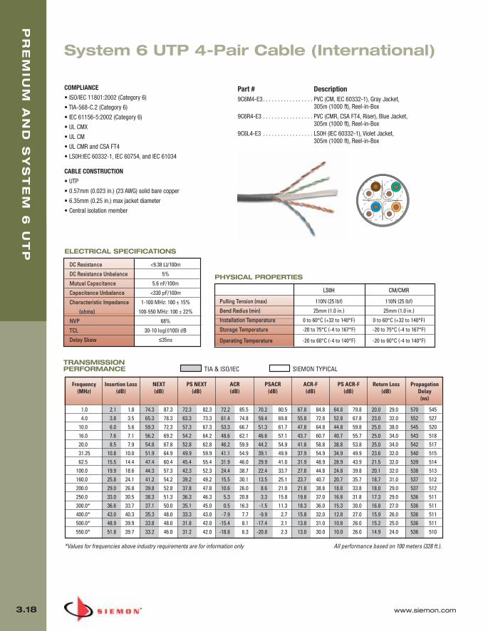
PR
EM
IUM
AN
D S
YS
TE
M 6
UT
P
3.18 www.siemon.com
TRANSMISSIONPERFORMANCE TIA & ISO/IEC SIEMON TYPICAL
All performance based on 100 meters (328 ft.).
COMPLIANCE
• ISO/IEC 11801:2002 (Category 6)
• TIA-568-C.2 (Category 6)
• IEC 61156-5:2002 (Category 6)
• UL CMX
• UL CM
• UL CMR and CSA FT4
• LS0H:IEC 60332-1, IEC 60754, and IEC 61034
CABLE CONSTRUCTION
• UTP
• 0.57mm (0.023 in.) (23 AWG) solid bare copper
• 6.35mm (0.25 in.) max jacket diameter
• Central isolation member
Part # Description9C6M4-E3. . . . . . . . . . . . . . . . . PVC (CM, IEC 60332-1), Gray Jacket,
305m (1000 ft), Reel-in-Box
9C6R4-E3 . . . . . . . . . . . . . . . . . PVC (CMR, CSA FT4, Riser), Blue Jacket, 305m (1000 ft), Reel-in-Box
9C6L4-E3 . . . . . . . . . . . . . . . . . LS0H (IEC 60332-1), Violet Jacket, 305m (1000 ft), Reel-in-Box
*Values for frequencies above industry requirements are for information only
Frequency Insertion Loss NEXT PS NEXT ACR PSACR ACR-F PS ACR-F Return Loss Propagation(MHz) (dB) (dB) (dB) (dB) (dB) (dB) (dB) (dB) Delay
(ns)
1.0 2.1 1.8 74.3 87.3 72.3 82.3 72.2 85.5 70.2 80.5 67.8 84.8 64.8 79.8 20.0 29.0 570 5454.0 3.8 3.5 65.3 78.3 63.3 73.3 61.4 74.8 59.4 69.8 55.8 72.8 52.8 67.8 23.0 32.0 552 527
10.0 6.0 5.6 59.3 72.3 57.3 67.3 53.3 66.7 51.3 61.7 47.8 64.8 44.8 59.8 25.0 38.0 545 52016.0 7.6 7.1 56.2 69.2 54.2 64.2 48.6 62.1 46.6 57.1 43.7 60.7 40.7 55.7 25.0 34.0 543 51820.0 8.5 7.9 54.8 67.8 52.8 62.8 46.2 59.9 44.2 54.9 41.8 58.8 38.8 53.8 25.0 34.0 542 51731.25 10.8 10.0 51.9 64.9 49.9 59.9 41.1 54.9 39.1 49.9 37.9 54.9 34.9 49.9 23.6 32.0 540 51562.5 15.5 14.4 47.4 60.4 45.4 55.4 31.9 46.0 29.9 41.0 31.9 48.9 28.9 43.9 21.5 32.0 539 514
100.0 19.9 18.6 44.3 57.3 42.3 52.3 24.4 38.7 22.4 33.7 27.8 44.8 24.8 39.8 20.1 32.0 538 513160.0 25.8 24.1 41.2 54.2 39.2 49.2 15.5 30.1 13.5 25.1 23.7 40.7 20.7 35.7 18.7 31.0 537 512200.0 29.0 26.8 39.8 52.8 37.8 47.8 10.6 26.0 8.6 21.0 21.8 38.8 18.8 33.8 18.0 29.0 537 512250.0 33.0 30.5 38.3 51.3 36.3 46.3 5.3 20.8 3.3 15.8 19.8 37.0 16.8 31.8 17.3 29.0 536 511300.0* 36.6 33.7 37.1 50.0 35.1 45.0 0.5 16.3 -1.5 11.3 18.3 36.0 15.3 30.0 16.8 27.0 536 511400.0* 43.0 40.3 35.3 48.0 33.3 43.0 -7.9 7.7 -9.9 2.7 15.8 32.0 12.8 27.0 15.9 26.0 536 511500.0* 48.9 39.9 33.8 48.0 31.8 42.0 -15.4 8.1 -17.4 2.1 13.8 31.0 10.8 26.0 15.2 25.0 536 511550.0* 51.8 39.7 33.2 46.0 31.2 42.0 -18.8 6.3 -20.8 2.3 13.0 30.0 10.0 26.0 14.9 24.0 536 510
LS0H CM/CMR
Pulling Tension (max) 110N (25 lbf) 110N (25 lbf)
Bend Radius (min) 25mm (1.0 in.) 25mm (1.0 in.)
Installation Temperature 0 to 60°C (+32 to 140°F) 0 to 60°C (+32 to 140°F)
Storage Temperature -20 to 75°C (-4 to 167°F) -20 to 75°C (-4 to 167°F)
Operating Temperature -20 to 60°C (-4 to 140°F) -20 to 60°C (-4 to 140°F)
PHYSICAL PROPERTIES
DC Resistance <9.38 Ω/100m
DC Resistance Unbalance 5%
Mutual Capacitance 5.6 nF/100m
Capacitance Unbalance <330 pF/100m
Characteristic Impedance 1-100 MHz: 100 ± 15%
(ohms) 100-550 MHz: 100 ± 22%
NVP 68%
TCL 30-10 log(f/100) dB
Delay Skew ≤35ns
ELECTRICAL SPECIFICATIONS
System 6 UTP 4-Pair Cable (International)
03_Premium6_UTP.qxd:ZMax_Catalog 1/4/10 11:21 AM Page 19
www.siemon.com
PR
EM
IUM
AN
D S
YS
TE
M 6
UT
P
3.19
03_Premium6_UTP.qxd:ZMax_Catalog 1/4/10 11:21 AM Page 20

PR
EM
IUM
AN
D S
YS
TE
M 5
eF
/UT
P
4.0 www.siemon.com
Premium 5e® and System 5e® F/UTP
Siemon’s Premium 5e F/UTP end-to-end cabling system is guaranteed to providetransmission performance margins in excess of industry standards for category 5eparameters, while featuring excellent EMI resistance. Premium 5e F/UTP has beenindependently verified to perform to 160 MHz.
All components are approved for use in a Premium 5e channel unless otherwiseindicated as a System 5e component. Only Premium 5e components are eligible for usein a Premium 5e channel.
Siemon’s System 5e F/UTP solution is designed for 100 MHz category 5e/class D installationsin which additional performance margins provided by the Premium 5e solution are notrequired.
Components specifically designed for use in System 5e channels are indicated by producttitle. Both System 5e and Premium 5e components are eligible for use in a System 5echannel.
SECTION CONTENTS
MAX® 5e Shielded Modules . . . . . . . . . . . . . . . . . . . . . . . . . . . . . . . . . 4.1
TERA®-MAX Shielded Patch Panels . . . . . . . . . . . . . . . . . . . . . . . . . . .4.2
System 5e Shielded HD® Panel . . . . . . . . . . . . . . . . . . . . . . . . . . . . . .4.2
HD Panel Accessories . . . . . . . . . . . . . . . . . . . . . . . . . . . . . . . . . . . . . .4.2
BladePatch® 5e Shielded Modular Cords . . . . . . . . . . . . . . . . . . . . . . .4.3
MC® 5 Shielded Modular Cords . . . . . . . . . . . . . . . . . . . . . . . . . . . . . .4.4
System 5e® F/UTP Cable (US) . . . . . . . . . . . . . . . . . . . . . . . . . . . . . . . .4.5
Premium 5e® F/UTP Cable (International) . . . . . . . . . . . . . . . . . . . . . . .4.6
04_Premium_5E_FUTP.qxd:ZMax_Catalog 1/19/10 3:03 PM Page 1

www.siemon.com
PR
EM
IUM
AN
D S
YS
TE
M 5
E F
/UT
P
4.1
1
2
3
4
56
MAX® 5e Shielded Modules
The shielded MAX module is the cornerstone of our category 5escreened cabling systems. This product not only meets all TIA/EIAcomponent specifications, but also exceeds ISO/IEC 11801 2nd editionand EN50173 2nd edition requirements for transfer impedance andshield effectiveness.
Fully Shielded — Design optimizes shieldeffectiveness for protection from EMI
Easy Identification — Colored iconsprovided for port identification
Rear Shield Protection — Robust rearshield protects IDC terminations andmaintains shield effectiveness
Easy Termination — Press-fit terminationmakes installation quick and easy
Universal Compatibility — Compatible withboth T568A/B schemes
Integrated Grounding — No separategrounding tabs required
1 4
2
3
5
6
Simple Termination Category 5e shielded MAX modules can beterminated in less than three minutes.
Quick-Ground™
TerminationNo additional steps required fortermination. Cable shield is automaticallyterminated within the outlet withoutadditional steps or tools.
For the TelecommunicationsRoom and Work AreaCategory 5e shielded MAX is designed for usewith both TERA®-MAX patch panels and 10GMAX faceplates.
MAX 5e SHIELDED MODULESOutlets terminate all shielded and shielded cable constructions 22 – 24 AWG (0.64 – 0.51mm) size conductors.
Flat and angled modules include one red and one blue icon.Note: Keystone version is designed for integration with various international mounting products and isnot compatible with MAX mounting hardware.Doors available separately.
Add “B” for bulk project pack of 100 modules.
MX5-FS . . . . . . . . . . . . . . . . . . .
Flat category 5e shielded MAX module,T568A/B
Technical Tip!Shielded MAX modules are not side-stackable instandard MAX faceplates. 10G MAX faceplates arerecommended.
MX5-KS. . . . . . . . . . . . . . . . . . .
Keystone category 5e screened MAX module,T568A/B
MX5-S. . . . . . . . . . . . . . . . . . . .
Angled category 5e shielded MAX module,T568A/B
04_Premium_5E_FUTP.qxd:ZMax_Catalog 1/19/10 3:03 PM Page 2
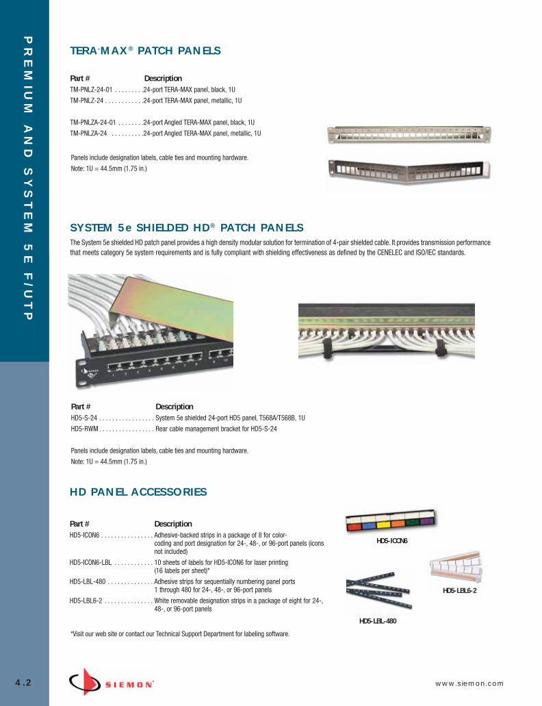
PR
EM
IUM
AN
D S
YS
TE
M 5
E F
/UT
P
4.2 www.siemon.com
TERA-MAX® PATCH PANELS
Part # DescriptionTM-PNLZ-24-01 . . . . . . . . .24-port TERA-MAX panel, black, 1U
TM-PNLZ-24 . . . . . . . . . . . .24-port TERA-MAX panel, metallic, 1U
TM-PNLZA-24-01 . . . . . . . .24-port Angled TERA-MAX panel, black, 1U
TM-PNLZA-24 . . . . . . . . . .24-port Angled TERA-MAX panel, metallic, 1U
Panels include designation labels, cable ties and mounting hardware.
Note: 1U = 44.5mm (1.75 in.)
SYSTEM 5e SHIELDED HD® PATCH PANELSThe System 5e shielded HD patch panel provides a high density modular solution for termination of 4-pair shielded cable. It provides transmission performancethat meets category 5e system requirements and is fully compliant with shielding effectiveness as defined by the CENELEC and ISO/IEC standards.
Part # DescriptionHD5-S-24 . . . . . . . . . . . . . . . . . System 5e shielded 24-port HD5 panel, T568A/T568B, 1U
HD5-RWM . . . . . . . . . . . . . . . . . Rear cable management bracket for HD5-S-24
Panels include designation labels, cable ties and mounting hardware.
Note: 1U = 44.5mm (1.75 in.)
HD PANEL ACCESSORIES
Part # DescriptionHD5-ICON6 . . . . . . . . . . . . . . . . Adhesive-backed strips in a package of 8 for color-
coding and port designation for 24-, 48-, or 96-port panels (iconsnot included)
HD5-ICON6-LBL . . . . . . . . . . . . 10 sheets of labels for HD5-ICON6 for laser printing (16 labels per sheet)*
HD5-LBL-480 . . . . . . . . . . . . . . Adhesive strips for sequentially numbering panel ports 1 through 480 for 24-, 48-, or 96-port panels
HD5-LBL6-2 . . . . . . . . . . . . . . . White removable designation strips in a package of eight for 24-,48-, or 96-port panels
HD5-LBL-480
HD5-LBL6-2
HD5-ICON6
*Visit our web site or contact our Technical Support Department for labeling software.
04_Premium_5E_FUTP.qxd:ZMax_Catalog 1/19/10 3:04 PM Page 3
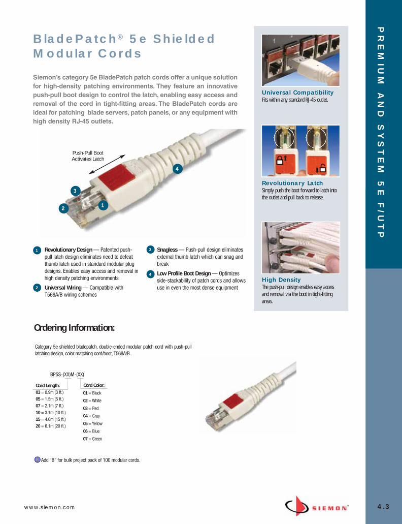
www.siemon.com
PR
EM
IUM
AN
D S
YS
TE
M 5
E F
/UT
P
4.3
Add “B” for bulk project pack of 100 modular cords.
12
3
4
Push-Pull Boot Activates Latch
Universal CompatibilityFits within any standard RJ-45 outlet.
Revolutionary LatchSimply push the boot forward to latch intothe outlet and pull back to release.
High DensityThe push-pull design enables easy accessand removal via the boot in tight-fittingareas.
Revolutionary Design — Patented push-pull latch design eliminates need to defeatthumb latch used in standard modular plugdesigns. Enables easy access and removal inhigh density patching environments
Universal Wiring — Compatible withT568A/B wiring schemes
Snagless — Push-pull design eliminatesexternal thumb latch which can snag andbreak
Low Profile Boot Design — Optimizesside-stackability of patch cords and allowsuse in even the most dense equipment
BladePatch® 5e ShieldedModular Cords
Siemon’s category 5e BladePatch patch cords offer a unique solutionfor high-density patching environments. They feature an innovativepush-pull boot design to control the latch, enabling easy access andremoval of the cord in tight-fitting areas. The BladePatch cords areideal for patching blade servers, patch panels, or any equipment withhigh density RJ-45 outlets.
BP5S-(XX)M-(XX)
Cord Length:03 = 0.9m (3 ft.)05 = 1.5m (5 ft.)07 = 2.1m (7 ft.)10 = 3.1m (10 ft.)15 = 4.6m (15 ft.)20 = 6.1m (20 ft.)
01 = Black
02 = White
03 = Red
04 = Gray
05 = Yellow
06 = Blue
07 = Green
Cord Color:
Category 5e shielded bladepatch, double-ended modular patch cord with push-pulllatching design, color matching cord/boot, T568A/B.
Ordering Information:
1
2
3
4
04_Premium_5E_FUTP.qxd:ZMax_Catalog 1/19/10 3:04 PM Page 4

PR
EM
IUM
AN
D S
YS
TE
M 5
E F
/UT
P
4.4 www.siemon.com
MC® 5e Shielded ModularCords
Siemon’s shielded MC 5e modular cords are manufactured usingstranded shielded cable that meets all category 5e specifications.Modular plugs have an overall shield and meet TIA-968-A and IEC60603-7 specifications. T568A/B wired assemblies include coloredstrain-relief boots and are available in a wide range of lengths.
Factory-TestedCords are factory terminated andtransmission tested to ensure compliancewith applicable standards requirements.
Universal Wiring — Compatiblewith T568A/B wiring schemes
Latch Guard — Boots feature alatch guard to protect plug fromsnagging when pulling throughpathways or cable managers
Color Options — Variety of coloroptions available for circuitidentification
Superior Quality — Quality plugcomponents ensure long termresistance to corrosion fromhumidity, extreme temperatures, andairborne contaminants
Technical Tip!Factory terminated and tested modular cords are required to achieve consistent category 5e compatibility. Fieldtermination is not recommended and is not compliant with Siemon warranty.
Compliance• Plug geometry meets TIA-968-A and IEC
60603-7 specifications for modular plugs• Exceeds ISO/IEC 11801:2002
requirements for transfer impedance,coupling attenuation and shieldeffectiveness
• Stranded Cable: IEC 61156-6:2002Compliant
• LS0H Cordage: IEC 60332-1, IEC 60754,and IEC 61034 compliant
Excellent Bend ReliefBoot ensures proper bend relief.
MC5S-(XX)M-(XX)
Cord Length:
01 = Black 02 = White03 = Red04 = Gray 05 = Yellow 06 = Blue 07 = Green
Cord Color:
Ordering Information: Category 5e screened MC, double-ended 4-pair stranded modular cord, color matching jacket/boot,T568A/B, LSOH
1 3
4
2
3
4
1
2
Add “B” to end of part number for bulk project pack of 100 cords.
03 = 0.9m (3 ft.)05 = 1.5m (5 ft.)07 = 2.1m (7 ft.)10 = 3.1m (10 ft.)15 = 4.6m (15 ft.)20 = 6.1m (20 ft.)
04_Premium_5E_FUTP.qxd:ZMax_Catalog 1/19/10 3:04 PM Page 5
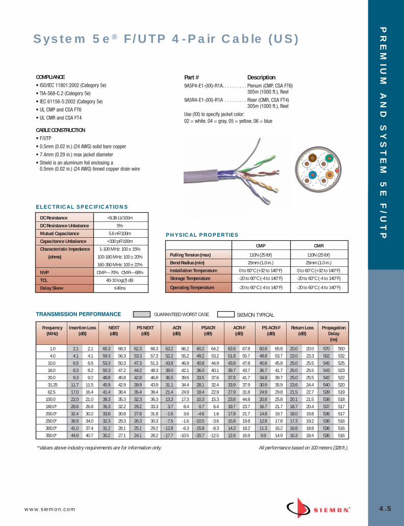
www.siemon.com
PR
EM
IUM
AN
D S
YS
TE
M 5
E F
/UT
P
4.5
TRANSMISSION PERFORMANCE GUARANTEED WORST CASE SIEMON TYPICAL
System 5e® F/UTP 4-Pair Cable (US)
COMPLIANCE
• ISO/IEC 11801:2002 (Category 5e)
• TIA-568-C.2 (Category 5e)
• IEC 61156-5:2002 (Category 5e)
• UL CMP and CSA FT6
• UL CMR and CSA FT4
CABLE CONSTRUCTION
• F/UTP
• 0.5mm (0.02 in.) (24 AWG) solid bare copper
• 7.4mm (0.29 in.) max jacket diameter
• Shield is an aluminum foil enclosing a 0.5mm (0.02 in.) (24 AWG) tinned copper drain wire
Part # Description9A5P4-E1-(XX)-R1A. . . . . . . . . . Plenum (CMP, CSA FT6)
305m (1000 ft.), Reel
9A5R4-E1-(XX)-R1A . . . . . . . . . Riser (CMR, CSA FT4) 305m (1000 ft.), Reel
Use (XX) to specify jacket color: 02 = white, 04 = gray, 05 = yellow, 06 = blue
Frequency Insertion Loss NEXT PS NEXT ACR PSACR ACR-F PS ACR-F Return Loss Propagation(MHz) (dB) (dB) (dB) (dB) (dB) (dB) (dB) (dB) Delay
(ns)
1.0 2.1 2.1 65.3 68.3 62.3 66.3 63.2 66.2 60.2 64.2 63.8 67.8 60.8 65.8 20.0 20.0 570 5504.0 4.1 4.1 59.3 56.3 53.3 57.3 52.2 55.2 49.2 53.2 51.8 55.7 48.8 53.7 23.0 23.3 552 532
10.0 6.5 6.5 53.3 50.3 47.3 51.3 43.8 46.9 40.8 44.9 43.8 47.8 40.8 45.8 25.0 25.5 545 52516.0 8.3 8.2 50.3 47.2 44.2 48.3 39.0 42.1 36.0 40.1 39.7 43.7 36.7 41.7 25.0 25.5 543 52320.0 9.3 9.2 48.8 45.8 42.8 46.8 36.5 39.6 33.5 37.6 37.8 41.7 34.8 39.7 25.0 25.5 542 52231.25 11.7 11.5 45.9 42.9 39.9 43.9 31.1 34.4 28.1 32.4 33.9 37.9 30.9 35.9 23.6 24.4 540 52062.5 17.0 16.4 41.4 38.4 35.4 39.4 21.4 24.9 18.4 22.9 27.9 31.8 24.9 29.8 21.5 22.7 539 519
100.0 22.0 21.0 38.3 35.3 32.3 36.3 13.3 17.3 10.3 15.3 23.8 44.8 20.8 25.8 20.1 21.5 538 518160.0* 28.6 26.8 35.3 32.2 29.2 33.3 3.7 8.4 0.7 6.4 19.7 23.7 16.7 21.7 18.7 20.4 537 517200.0* 32.4 30.2 33.8 30.8 27.8 31.8 -1.6 3.6 -4.6 1.6 17.8 21.7 14.8 19.7 18.0 19.8 536 517250.0* 36.9 34.0 32.3 29.3 26.3 30.3 -7.5 -1.6 -10.5 -3.6 15.8 19.8 12.8 17.8 17.3 19.2 536 516300.0* 41.0 37.4 31.2 28.1 25.1 29.2 -12.8 -6.3 -15.8 -8.3 14.3 18.2 11.3 16.2 16.8 18.8 536 516350.0* 44.9 40.7 30.2 27.1 24.1 28.2 -17.7 -10.5 -20.7 -12.5 12.9 16.9 9.9 14.9 16.3 18.4 536 516
*Values above industry requirements are for information only. All performance based on 100 meters (328 ft.).
DC Resistance <9.38 Ω/100m
DC Resistance Unbalance 5%
Mutual Capacitance 5.6 nF/100m
Capacitance Unbalance <330 pF/100m
Characteristic Impedance 1-100 MHz: 100 ± 15%
(ohms) 100-160 MHz: 100 ± 20%
160-350 MHz: 100 ± 22%
NVP CMP—70% CMR—68%
TCL 40-10 log(f) dB
Delay Skew ≤40ns
ELECTRICAL SPECIFICATIONS
CMP CMR
Pulling Tension (max) 110N (25 lbf) 110N (25 lbf)
Bend Radius (min) 25mm (1.0 in.) 25mm (1.0 in.)
Installation Temperature 0 to 60°C (+32 to 140°F) 0 to 60°C (+32 to 140°F)
Storage Temperature -20 to 60°C (-4 to 140°F) -20 to 60°C (-4 to 140°F)
Operating Temperature -20 to 60°C (-4 to 140°F) -20 to 60°C (-4 to 140°F)
PHYSICAL PROPERTIES
04_Premium_5E_FUTP.qxd:ZMax_Catalog 1/19/10 3:04 PM Page 6

Premium 5e® F/UTP 4-Pair Cable(International)
PR
EM
IUM
AN
D S
YS
TE
M 5
E F
/UT
P
4.6 www.siemon.com
TRANSMISSION PERFORMANCE TIA & ISO/IEC SIEMON TYPICAL
COMPLIANCE• ISO/IEC 11801:2002 (Category 5e)
• TIA-568-C2 (Category 5e)
• IEC 61156-5:2002 (Category 5e)
• UL CM
• UL CMR and CSA FT4
• LS0H: IEC 60332-1, IEC 60754 and IEC 61034
CABLE CONSTRUCTION• F/UTP
• 0.5mm (0.02 in.) (24 AWG) solid bare copper
• 7.4mm (0.29 in.) max jacket diameter
• Shield is an aluminum foil tape enclosing a 0.5mm (0.02 in.) (24 AWG) tinned copper drain wire
Part # Description9A5M4-E2. . . . . . . . . . . . . . . . . PVC (CM, IEC 60332-1),Gray Jacket,
305m (1000 ft.) Reel-in-Box
9A5R4-E2 . . . . . . . . . . . . . . . . . PVC (CMR, CSA FT4, Riser),Blue Jacket, 305m (1000 ft.) Reel-in-Box
9A5L4-E2 . . . . . . . . . . . . . . . . . LS0H (IEC 60332-1), Violet Jacket, 305m (1000 ft.), Reel-in-Box
Frequency Insertion Loss NEXT PS NEXT ACR PSACR ACR-F PS ACR-F Return Loss Propagation(MHz) (dB) (dB) (dB) (dB) (dB) (dB) (dB) (dB) Delay
(ns)
1.0 2.1 1.9 65.3 79.3 62.3 72.3 63.2 77.4 60.2 70.4 63.8 84.8 60.8 78.8 20.0 27.0 570 5454.0 4.1 3.7 56.3 70.3 53.3 63.3 52.2 66.6 49.2 59.6 51.8 72.8 48.8 66.8 23.0 32.0 552 527
10.0 6.5 5.8 50.3 64.3 47.3 57.3 43.8 58.5 40.8 51.5 43.8 64.8 40.8 58.8 25.0 32.0 545 52016.0 8.3 7.4 47.2 61.2 44.2 54.2 39.0 53.8 36.0 46.8 39.7 60.7 36.7 54.7 25.0 32.0 543 51820.0 9.3 8.3 45.8 59.8 42.8 52.8 36.5 51.5 33.5 44.5 37.8 58.8 34.8 52.8 25.0 32.0 542 51731.25 11.7 10.5 42.9 56.9 39.9 49.9 31.1 46.4 28.1 39.4 33.9 54.9 30.9 48.9 23.6 30.0 540 51562.5 17.0 15.0 38.4 52.4 35.4 45.4 21.4 37.4 18.4 30.4 27.9 48.9 24.9 42.9 21.5 30.0 539 514
100.0 22.0 19.3 35.3 49.3 32.3 42.3 13.3 30.0 10.3 23.0 23.8 44.8 20.8 38.8 20.1 30.0 538 513160.0* 28.6 25.1 32.2 46.2 29.2 39.2 3.7 21.1 0.7 14.1 19.7 40.7 16.7 34.7 18.7 28.0 537 512200.0* 32.4 28.1 30.8 44.8 27.8 37.8 -1.6 16.7 -4.6 9.7 17.8 38.8 14.8 32.8 18.0 27.0 536 512250.0* 36.9 31.4 29.3 43.3 26.3 36.3 -7.5 11.9 -10.5 4.9 15.8 36.8 12.8 30.8 17.3 26.0 536 511300.0* 41.0 34.5 28.1 42.1 25.1 35.1 -12.8 7.6 -15.8 0.6 14.3 35.3 11.3 29.3 16.8 25.0 536 511350.0* 44.9 39.4 27.1 41.1 24.1 34.1 -17.7 1.7 -20.7 -5.3 12.9 33.9 9.9 27.9 16.3 24.0 536 511
*Values above industry requirements are for information only All performance based on 100 meters (328 ft.).
LS0H CM/CMR
Pulling Tension (max) 110N (25 lbf) 110N (25 lbf)
Bend Radius (min) 30mm (1.2 in.) 30mm (1.2 in.)
Installation Temperature 0 to 60°C (+32 to 140°F) 0 to 60°C (+32 to 140°F)
Storage Temperature -20 to 75°C (-4 to 167°F) -20 to 75°C (-4 to 167°F)
Operating Temperature -20 to 60°C (-4 to 140°F) -20 to 60°C (-4 to 140°F)
PHYSICAL PROPERTIES
DC Resistance <9.38 Ω/100m
DC Resistance Unbalance 5%
Mutual Capacitance 5.6 nF/100m
Capacitance Unbalance <330 pF/100m
Characteristic Impedance 1-100 MHz: 100 ± 15%
(ohms) 100-250 MHz: 100 ± 22%
NVP 69%
TCL 40-10 log(f) dB
Delay Skew ≤40ns
ELECTRICAL SPECIFICATIONS
04_Premium_5E_FUTP.qxd:ZMax_Catalog 1/19/10 3:04 PM Page 7
www.siemon.com
PR
EM
IUM
AN
D S
YS
TE
M 5
E F
\UT
P
4.7
04_Premium_5E_FUTP.qxd:ZMax_Catalog 1/19/10 3:04 PM Page 8

PR
EM
IUM
5e
AN
D S
YS
TE
M 5
eU
TP
5.0 www.siemon.com
Premium 5e® and System 5e® UTP
Siemon’s end-to-end Premium 5e UTP cabling solution is guaranteed to provide transmission per-formance margins in excess of industry standards for category 5e/class D parameters, and hasbeen independently verified to perform to 160 MHz.
All components are approved for use in a Premium 5e channel unless otherwise indicated as a System 5e component. Only Premium 5e components are eligible for use in a Premium 5e chan-nel.
Siemon’s System 5e UTP solution is designed for 100 MHz category 5e/class D installations inwhich additional performance margins provided by the Premium 5e solution are not required.
Components specifically designed for use in a System 5e channels are indicated by product title.Both System 5e and Premium 5e components are eligible for use in a System 5e channel.
SECTION CONTENTS
MAX® 5e UTP Modules . . . . . . . . . . . . . . . . . . . . . . . . . . . . . . . . . . . . 5.1
System 5e Tool-less MAX UTP Modules . . . . . . . . . . . . . . . . . . . . . . . .5.2
HD® 5e UTP Patch Panels . . . . . . . . . . . . . . . . . . . . . . . . . . . . . . . . . . .5.3
12-Port HD 5e Panel on S890 Bracket . . . . . . . . . . . . . . . . . . . . . . . . .5.3
MAX UTP Patch Panels . . . . . . . . . . . . . . . . . . . . . . . . . . . . . . . . . . . . .5.4
Angled MAX UTP Patch Panels . . . . . . . . . . . . . . . . . . . . . . . . . . . . . . .5.4
12-Port MAX UTP Panel on S89D Bracket . . . . . . . . . . . . . . . . . . . . . . .5.4
MAX Panel Accessories . . . . . . . . . . . . . . . . . . . . . . . . . . . . . . . . . . . .5.4
MC® 5e UTP Modular Cords . . . . . . . . . . . . . . . . . . . . . . . . . . . . . . . . .5.5
IC 5e UTP Solid Modular Cords . . . . . . . . . . . . . . . . . . . . . . . . . . . . . . .5.6
S110® to MC UTP Cable Assemblies . . . . . . . . . . . . . . . . . . . . . . . . . . .5.6
S110 Connection System . . . . . . . . . . . . . . . . . . . . . . . . . . . . . . . . . . .5.7
S110 Field Termination Kits . . . . . . . . . . . . . . . . . . . . . . . . . . . . . . . . .5.7
S110 Patch Plugs . . . . . . . . . . . . . . . . . . . . . . . . . . . . . . . . . . . . . . . . .5.8
S110 Cable Assemblies . . . . . . . . . . . . . . . . . . . . . . . . . . . . . . . . . . . .5.8
S110 19 Inch Field Termination Panels . . . . . . . . . . . . . . . . . . . . . . . . .5.9
S110 Tower Field Termination Kits . . . . . . . . . . . . . . . . . . . . . . . . . . . .5.9
M1-50 Block . . . . . . . . . . . . . . . . . . . . . . . . . . . . . . . . . . . . . . . . . . .5.10
Stand-Off Bracket for S66 Blocks . . . . . . . . . . . . . . . . . . . . . . . . . . . .5.10
Category 5e UTP Cross-Connect Wire . . . . . . . . . . . . . . . . . . . . . . . . .5.10
Premium 5e UTP Cable (US) . . . . . . . . . . . . . . . . . . . . . . . . . . . . . . . .5.11
Premium 5e UTP Cable (International) . . . . . . . . . . . . . . . . . . . . . . . .5.12
05_Premium_Sys_5E_UTP.qxd:ZMax_Catalog 1/8/10 9:11 AM Page 1

www.siemon.com
PR
EM
IUM
5e
AN
D S
YS
TE
M 5
eU
TP
5.1
12
3
4
5
6
Use (XX) to specify color: 01 = black, 02 = white, 03 = red, 04 = gray, 05 = yellow, 06 = blue, 07 = green, 09 = orange, 20 = ivory, 25 = bright white, 80 = light ivory
Angled modules include one color-matching, one red, and one blue icon. Door color is clear for red, yellow, blue and orange angled modules.
Flat modules include one color-matching, one red, and one blue icon.
Keystone version is designed for integration with various international mounting products and is not compatible with MAX mounting hardware.
Add “B” to end of part number for bulk project pack of 100 modules (angled and flat modules include icons).
Easy Installation — Install from either frontor rear of faceplate
Easy Termination — Punch-down withstandard 110 termination tools
Quick Identification — Icons provided forport identification
Slim Design — Allows jacks to be side-stacked in faceplates to provide maximumdensity
Universal Wiring — T568A and T568Bwiring compatible
Protective Doors — Minimize exposure todust and other contaminants
1 4
2
3
5
6
Quick InstallationPyramid wire entry system on S310®
blocks separates paired conductors whenlacing cables to simplify and reduceinstallation time.
TerminationSiemon’s Palm Guard with MAX insertassists in securing module duringtermination.
Superior PerformanceUse MC or BladePatch 5e modular cords toperfectly match performance of Premium5e MAX modules.
MX5-(XX) . . . . . . . . . . . . . . . . . .
Angled MAX module, T568A/B, rear strain relief cap and protective color-matching rubber door
MX5-F(XX) . . . . . . . . . . . . . . . . .
Flat MAX module, T568A/B,rear strain relief cap
MX5-K(XX). . . . . . . . . . . . . . . . .
Keystone MAX module, T568A/B, rear strain relief cap
MAX® 5e UTP Modules
MAX 5e modules exceed category 5e performance with component andchannel performance to 160 MHz. These modules offer all the functionaladvantages of our MAX 6 modules in a variety of color options. All mod-ules utilize our 310 punch-down block — making termination quick andeasy.
05_Premium_Sys_5E_UTP.qxd:ZMax_Catalog 1/8/10 9:12 AM Page 2

PR
EM
IUM
5e
AN
D S
YS
TE
M 5
eU
TP
5.2 www.siemon.com
MX-C5-(XX) . . . . . . . . . . . .
Angled module,T568A/B
MX-F-C5-(XX) . . . . . . . . . .
Flat module,T568A/B
Use (XX) to specify color: 01 = black, 02 = white, 03 = red, 04 = gray, 05 = yellow, 06 = blue, 09 = orange, 20 = ivory, 25 = bright white, 80 = light ivory
Add “-D” for optional door for angled and flat versions.
Door color is white for red, yellow, blue, and orange flat modules; clear for angled.
Add “B” to end of part number for bulk project pack of 100 modules.
Flat and Angled modules include one color-matching, one red, and one blue icon.
MX-K-C5-(XX) . . . . . . . . . . . . . .
Keystone module, T568A/B
Keystone version is designed for integration with various international mounting products and is not compatible with MAXmounting hardware.
01 02 03 04 05 06 09 20 25 80
Easy Termination — No terminationtools required
Quick Identification — Icon tabsavailable in 13 colors for color-coding
High-density Solutions — Slimdesign allows outlet to be side-stackable
Proven Performance — Patentedmulti-planar pair balancing technologyprovides category 5e systemperformance
Easy Installation — Flexiblemounting tab allows installation fromfront or rear of faceplate and securesmodule into the faceplate
1 4
2
3 5
Press-Fit TerminationMass terminate all eight conductors byhand or use a single-position S110®
termination tool in the MAX terminationcap.
Quick-Pair PlacementConductors can be sequentially placedinto termination cap, minimizing cablepair untwist and simplifying termination.
Verify Proper WiringThe termination cap has a large windowfor viewing terminations.
System 5e UTP Tool-LessMAX® Modules
The tool-less MAX module provides category 5e system performanceand user-friendly installation features. Our tool-less termination allows all eight conductors to be terminated simultaneously whenthe termination cap is pressed into place. The compact size provideshigh-density connectivity in the work area and telecommunicationsroom.
1
4
2
3
5
05_Premium_Sys_5E_UTP.qxd:ZMax_Catalog 1/8/10 9:12 AM Page 3
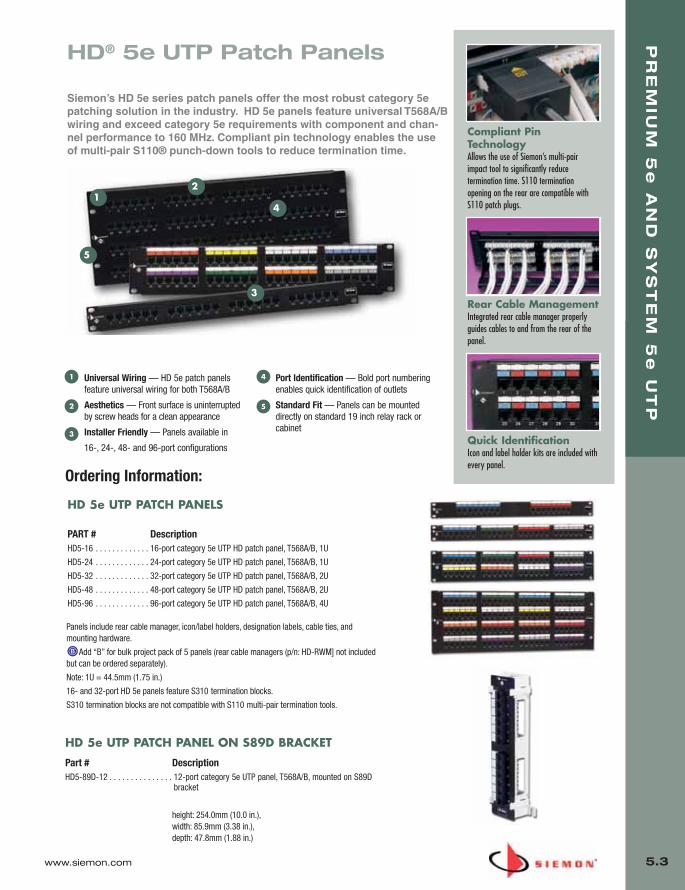
www.siemon.com
PR
EM
IUM
5e
AN
D S
YS
TE
M 5
eU
TP
5.3
12
3
4
5
HD 5e UTP PATCH PANELS
PART # DescriptionHD5-16 . . . . . . . . . . . . . 16-port category 5e UTP HD patch panel, T568A/B, 1U
HD5-24 . . . . . . . . . . . . . 24-port category 5e UTP HD patch panel, T568A/B, 1U
HD5-32 . . . . . . . . . . . . . 32-port category 5e UTP HD patch panel, T568A/B, 2U
HD5-48 . . . . . . . . . . . . . 48-port category 5e UTP HD patch panel, T568A/B, 2U
HD5-96 . . . . . . . . . . . . . 96-port category 5e UTP HD patch panel, T568A/B, 4U
Panels include rear cable manager, icon/label holders, designation labels, cable ties, andmounting hardware.
Add “B” for bulk project pack of 5 panels (rear cable managers (p/n: HD-RWM] not includedbut can be ordered separately).
Note: 1U = 44.5mm (1.75 in.)
16- and 32-port HD 5e panels feature S310 termination blocks.
S310 termination blocks are not compatible with S110 multi-pair termination tools.
Universal Wiring — HD 5e patch panelsfeature universal wiring for both T568A/B
Aesthetics — Front surface is uninterruptedby screw heads for a clean appearance
Installer Friendly — Panels available in
16-, 24-, 48- and 96-port configurations
Port Identification — Bold port numberingenables quick identification of outlets
Standard Fit — Panels can be mounteddirectly on standard 19 inch relay rack orcabinet
Rear Cable ManagementIntegrated rear cable manager properlyguides cables to and from the rear of thepanel.
Quick IdentificationIcon and label holder kits are included withevery panel.
Compliant PinTechnologyAllows the use of Siemon’s multi-pairimpact tool to significantly reducetermination time. S110 terminationopening on the rear are compatible withS110 patch plugs.
1 4
2
3
5
HD® 5e UTP Patch Panels
Siemon’s HD 5e series patch panels offer the most robust category 5epatching solution in the industry. HD 5e panels feature universal T568A/Bwiring and exceed category 5e requirements with component and chan-nel performance to 160 MHz. Compliant pin technology enables the useof multi-pair S110® punch-down tools to reduce termination time.
HD 5e UTP PATCH PANEL ON S89D BRACKET
Part # DescriptionHD5-89D-12 . . . . . . . . . . . . . . . 12-port category 5e UTP panel, T568A/B, mounted on S89D
bracket
height: 254.0mm (10.0 in.), width: 85.9mm (3.38 in.), depth: 47.8mm (1.88 in.)
Ordering Information:
05_Premium_Sys_5E_UTP.qxd:ZMax_Catalog 1/8/10 9:12 AM Page 4
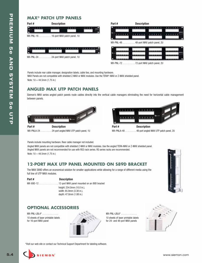
PR
EM
IUM
5e
AN
D S
YS
TE
M 5
eU
TP
5.4 www.siemon.com
Panels include rear cable manager, designation labels, cable ties, and mounting hardware.MAX Panels are not compatible with shielded Z-MAX or MAX modules. Use the TERA®-MAX or Z-MAX shielded panel.
Note: 1U = 44.5mm (1.75 in.)
MAX® PATCH UTP PANELS
MX-PNL-16 . . . . . . . . . . 16-port MAX patch panel, 1U
MX-PNL-48 . . . . . . . . . . 48-port MAX patch panel, 2U
MX-PNL-24 . . . . . . . . . . 24-port MAX patch panel, 1U
MX-PNL-72 . . . . . . . . . . 72-port MAX patch panel, 2U
ANGLED MAX UTP PATCH PANELSSiemon’s MAX series angled patch panels route cables directly into the vertical cable managers eliminating the need for horizontal cable managementbetween panels.
Part # DescriptionMX-PNLA-24 . . . . . . . . . 24-port angled MAX UTP patch panel, 1U
Part # DescriptionMX-PNLA-48 . . . . . . . . . 48-port angled MAX UTP patch panel, 2U
12-PORT MAX UTP PANEL MOUNTED ON S89D BRACKETThe MAX S89D offers an economical solution for smaller applications while allowing for a range of different media using thefull line of UTP MAX modules.
Part # DescriptionMX-89D-12 . . . . . . . . . . . . . . . . 12-port MAX panel mounted on an 89D bracket
height: 254.0mm (10.0 in.), width: 85.9mm (3.38 in.), depth: 47.8mm (1.88 in.)
MX-PNL-LBL4* . . . . . . . . . . . . .
10 sheets of laser printable labels for 16-port MAX panel
MX-PNL-LBL6* . . . . . . . . . . . . .
10 sheets of laser printable labels for 24- and 48-port MAX panels
*Visit our web site or contact our Technical Support Department for labeling software.
Part # Description Part # Description
OPTIONAL ACCESSORIES
Panels include mounting hardware. Rear cable manager not included.
Angled MAX panels are not compatible with shielded Z-MAX or MAX modules. Use the angled TERA-MAX or Z-MAX shielded panel.Angled MAX panels are not recommended for use with RS3 rack series. RS series racks are recommended.
Note: 1U = 44.5mm (1.75 in.)
05_Premium_Sys_5E_UTP.qxd:ZMax_Catalog 1/8/10 9:12 AM Page 5

www.siemon.com
PR
EM
IUM
5e
AN
D S
YS
TE
M 5
eU
TP
5.5
Category 5e UTP MC double-ended, 4-pair strandedmodular cord, color matching jacket/boot, T568A/B, CMG
Latch GuardThe MC 5e boot design incorporates a latchguard to protect the plug latch fromsnagging when pulling cords throughpathways or cable managers.
Factory TerminatedCords are tested to consistently achievecategory 5e compatibility. Field terminationis not recommended.
MC® 5e UTP Modular Cords
Siemon uses the highest quality components combined with stringentmanufacturing processes to produce the best performing, mostdurable modular patch cords available. The end result is a cord thatexceeds all TIA/IEA and ISO/IEC component specifications for trans-mission performance.
MC5-8T-(XX)-B(XX)
Cord Color:Cord Length:03 = 0.9m (3 ft.)05 = 1.5m (5 ft.)07 = 2.1m (7 ft.)10 = 3.1m (10 ft.)15 = 4.6m (15 ft.)20 = 6.1m (20 ft.)
01 = Black 02 = White 03 = Red04 = Gray 05 = Yellow 06 = Blue07 = Green
MC5-8-T-(XX)(XX)
Cord Length:03 = 0.9m (3 ft.)05 = 1.5m (5 ft.)07 = 2.1m (7 ft.)10 = 3.1m (10 ft.)15 = 4.6m (15 ft.)20 = 6.1m (20 ft.)
Category 5e UTP MC double-ended, 4-pair stranded modular cord, no boot, T568A/B, CMG
Add “B” to end of part number for bulk project pack of 100 cords
Bend Fatigue — 24 AWG (7 strands @0.20mm) stranded wire for longer bendfatigue life
High Performance — MC 5e cords areconstructed using high performance Siemoncategory 5e cable
Modular Plugs — Exceed FCC CFR 47 part68 subpart F and IEC 60603-7 specificationsand have 50 microinches minimum of goldplating over nickel
1
2
3
1
2
3
Cord Color:01 = Black 02 = White 03 = Red04 = Gray 05 = Yellow 06 = Blue07 = Green
05_Premium_Sys_5E_UTP.qxd:ZMax_Catalog 1/8/10 9:12 AM Page 6

PR
EM
IUM
5e
AN
D S
YS
TE
M 5
eU
TP
5.6 www.siemon.com
IC 5e SOLID UTP SINGLE-ENDED MODULAR CORDSSiemon’s solid, single-ended IC5e cable assemblies are designed for patching between the consolidation point andthe work area (CMP) or as equipment cords in cross-connect applications (CMR). These assemblies are constructedusing cable that exceeds all category 5e specifications.
Part # Description
IC5-8(X)-(XX)R . . . . . . . . . . . . . . Category 5e IC, single-ended, 4-pair UTP solid modular cord, blue jacket, w/o boot, CMR
IC5-8(X)-(XX)P . . . . . . . . . . . . . . Category 5e IC, single-ended, 4-pair UTP solid modular cord, blue jacket, w/o boot, CMP
IC5-8(X)-(XX)-B(XX)R . . . . . . . . . Category 5e IC, single-ended, 4-pair UTP solid modular cord, blue jacket, with colored boot, CMR
IC5-8(X)-(XX)-B(XX)P . . . . . . . . . Category 5e IC, single-ended, 4-pair UTP solid modular cord, blue jacket, with colored boot, CMP
Use (X) to specify wiring: A =T568B, T=T568A
Use 1st (XX) to specify cord length: 10 = 3.1m (10 ft.), 20 = 6.1m (20 ft.), 30 = 9.1m (30 ft.), 40 = 12.2m (40 ft.), 50 = 15.2 (50 ft.), 60 = 18.3m (60 ft.)
Use 2nd (XX) to specify boot color: 01 = black, 02 = white, 03 = red, 04 = green, 05 = yellow, 06 = blue, 07=green
S110® TO MC® CABLE ASSEMBLIESThe S110 to modular cable assemblies combine Siemon’s high performance modular plugs for patching networkequipment to S110 connecting blocks or providing test access to S110 termination fields. The combination of plugs,high performance cable and factory transmission testing ensures performance is compatible with Premium 5esystems.
Part # DescriptionS110P4-A4-(XX) . . . . . . . . . . . . Category 5e, 4-pair, S110-to-modular plug, T568B,
standard cable assembly, CMG
S110P4-T4-(XX) . . . . . . . . . . . . Category 5e, 4-pair, S110-to-modular plug, T568A, standard cable assembly, CMG
S110P2-UT-(XX) . . . . . . . . . . . . Category 5e, 2-pair, S110-to-modular 8-position plug, Token Ring, T568A, standard cable assembly, CMG
S110P2-E2-(XX) . . . . . . . . . . . . Category 5e, 2-pair, S110-to-modular 8-position plug, 10/100BASE-T, T568B, standard cable assembly, CMG
S110P1-U1-(XX) . . . . . . . . . . . . Category 5e, 1-pair, S110-to-modular 6-position plug, USOC, standard cable assembly, CMG
S110P1-U4-(XX) . . . . . . . . . . . . Category 5e, 1-pair, S110-to-modular 8-position plug, USOC, standard cable assembly, CMG
Use 1st (XX) to specify length: 03 = 0.91m (3 ft.), 05 = 1.5m (5 ft.), 07 = 2.13m (7 ft.), 10 = 3.05m (10 ft.), 15 = 4.57m (15 ft.), 20 = 6.10m (20 ft.)
05_Premium_Sys_5E_UTP.qxd:ZMax_Catalog 1/8/10 9:12 AM Page 7
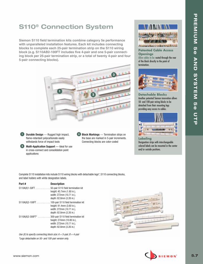
www.siemon.com
PR
EM
IUM
5e
AN
D S
YS
TE
M 5
eU
TP
5.7
Durable Design — Rugged high impact,flame-retardant polycarbonate easilywithstands force of impact tools
Multi-Application Support — Ideal for usein cross-connect and consolidation pointapplications
Block Markings — Termination strips onthe base are marked in 5-pair increments.Connecting blocks are color-coded
1
2
3
Patented Cable AccessOpeningsAllow cables to be routed through the rearof the block directly to the point oftermination.
Detachable BlocksAnother patented Siemon innovation allows50- and 100-pair wiring blocks to bedetached from their mounting legsproviding easy access to cables.
LabelingDesignation strips with interchangeablecolored labels can be mounted in the centerand/or outside positions.
1
3
2
Complete S110 installation kits include S110 wiring blocks with detachable legs*, S110 connecting blocks,and label holders with white designation labels.
Part # DescriptionS110A(X)1-50FT . . . . . . . . . . . . 50-pair S110 field termination kit
height: 45.7mm (1.80 in.), width: 272mm (10.71 in.), depth: 82.8mm (3.26 in.)
S110A(X)2-100FT . . . . . . . . . . . 100-pair S110 field termination kitheight: 91.4mm (3.60 in.), width: 272mm (10.71 in.), depth: 82.8mm (3.26 in.)
S110A(X)2-300FT* . . . . . . . . . . 300-pair S110 field termination kitheight: 274mm (10.80 in.), width: 272mm (10.71 in.), depth: 82.8mm (3.26 in.)
Use (X) to specify connecting block size: A = 5-pair, B = 4-pair
*Legs detachable on 50- and 100-pair version only.
S110® Connection System
Siemon S110 field termination kits combine category 5e performancewith unparalleled installation features. Each kit includes connectingblocks to complete each 25-pair termination strip on the S110 wiringblock (e.g. S110AB2-100FT includes five 4-pair and one 5-pair connect-ing block per 25-pair termination strip, or a total of twenty 4-pair and four5-pair connecting blocks).
05_Premium_Sys_5E_UTP.qxd:ZMax_Catalog 1/8/10 9:12 AM Page 8

PR
EM
IUM
5e
AN
D S
YS
TE
M 5
eU
TP
5.8 www.siemon.com
Add “-B” to end of part number for bulk project pack of 100 patch plugs.
*S110P1 includes protective insert for use with single pair cross-connect wire.
Colored icons are available for color-coding 4-pair S110 plugs (sold seperately)
S110P2 . . . . . . . . . . . . . . . . . . .
2-pair, field-terminated, S110 patch plug
S110P4 . . . . . . . . . . . . . . . . . . .
4-pair, field-terminated, S110 patch plug
S110P1* . . . . . . . . . . . . . . . . . .
1-pair, field-terminated, S110 patch plug
S110 CABLE ASSEMBLIESThe S110 cable assemblies utilize Siemon’s S110P4 patch plugs for easy and reliable connections between S110 termination fields. These assemblies use highperformance stranded cable which exceeds category 5e specifications and are factory transmission tested to ensure optimum category 5e channel performance.Colored icons are available for color-coding 4-pair S110 plugs.
Part # DescriptionS110P4-P4-(XX) . . . . . . . . . . . . 4-pair, double-ended stranded S110 cord, CMG
S110P2-P2-(XX) . . . . . . . . . . . . 2-pair, double-ended stranded S110 cord, CMG
S110P1-P1-(XX) . . . . . . . . . . . . 1-pair, double-ended stranded S110 cord, CMG
Use (XX) to specify length:
03 = 0.91m (3 ft.), 05 = 1.5m (5 ft.), 07 = 2.13m (7 ft.), 10 = 3.05m (10 ft.), 15 = 4.57m (15 ft.), 20 = 6.10m (20 ft.)
Ergonomic Handle — Aids insertionand removal of patch plug
Clear Housing — Durable, flame-retardant, clear thermoplastic housingkeeps conductors visible during andafter termination
Polarization — Each plug housingincludes polarization features to ensureproper tip-ring orientation duringconnection
1
2
3
Field InstallableTerminates 24-26 AWG (0.40mm-0.51mm)solid or 7-strand twisted-pair UTP cable.
Easy TerminationSimply snap the base and cover together tomass terminate all conductors.
S110® Patch Plugs
Siemon S110 patch plugs are both category 5e compliant and canbe field-terminated to either solid or stranded cable. 4-pair S110patch plugs employ a patented design to improve electrical isola-tion between pairs, enhancing cross-talk performance so that themated plug and connecting block significantly exceed category 5etransmission requirements.
1
3
2
05_Premium_Sys_5E_UTP.qxd:ZMax_Catalog 1/8/10 9:12 AM Page 9

www.siemon.com
PR
EM
IUM
5e
AN
D S
YS
TE
M 5
eU
TP
5.9
S110® 19 INCH FIELD TERMINATION PANELSS110 panels allow wiring blocks to be mounted directly to a 19 inch CEA rack or cabinet.Each panel includes adequate connecting blocks to complete each 25-pair termination stripon the S110 block (e.g. S110DB1-100RFT would include five 4-pair and one 5-pair connect-ing block per 25-pair termination strip, or a total of twenty 4-pair and four 5-pair connectingblocks).
Part # DescriptionS110D(X)1-100RFT . . . . . . . . . .100-pair, 19 inch panel, S110 field termination kit, 1U
S110D(X)1-200RFT . . . . . . . . . .200-pair, 19 inch panel, S110 field termination kit, 2U
S110D(X)1-300RFT . . . . . . . . . .300-pair, 19 inch panel, S110 field termination kit, 3U
Use (X) to specify connecting block size: A = 5-pair, B = 4-pair
Note: 1U = 44.5mm (1.75 in.)
S188-WD
Tower with S188
S110 TOWER® FIELD TERMINATION KITSThe S110 Tower System provides a modular high-density cross-connect cable management system.S110 Tower Systems are shipped unassembled to simplify field assembly and termination.
Part # DescriptionS110M(X)2-300FT . . . . . . . . . . . 300-pair S110 Tower field termination kit
height: 406.4mm (16 in.), width: 215.9mm (8.5 in.), depth: 152.6mm (6 in.)
S110M(X)2-400FT . . . . . . . . . . . 400-pair S110 Tower field termination kitheight: 541.3mm (21.3 in.), width: 215.9mm (8.5 in.), depth: 152.6mm (6 in.)
S110M(X)2-500FT . . . . . . . . . . . 500-pair S110 Tower field termination kitheight: 676.1mm (26.6 in.), width: 215.9mm (8.5 in.), depth: 152.6mm (6 in.)
Use (X) to specify connecting block size: A = 5-pair, B = 4-pair
S110 TOWER OPTIONAL ACCESSORIESPart # DescriptionS188-300 . . . . . . . . . . . . . . . . . Large-scale vertical cable manager for use with 300-pair tower
S188-400 . . . . . . . . . . . . . . . . . Large-scale vertical cable manager for use with 400-pair tower
S188-500 . . . . . . . . . . . . . . . . . Large-scale vertical cable manager for use with 500-pair tower
S188-WD . . . . . . . . . . . . . . . . . Metal duct for additional horizontal cable management at base of Tower units
05_Premium_Sys_5E_UTP.qxd:ZMax_Catalog 1/8/10 9:12 AM Page 10
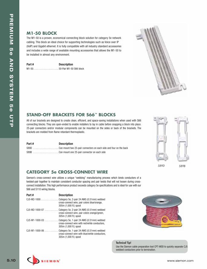
PR
EM
IUM
5e
AN
D S
YS
TE
M 5
eU
TP
5.10 www.siemon.com
M1-50 BLOCKThe M1-50 is a proven, economical connecting block solution for category 5e networkcabling. This block an ideal choice for supporting technologies such as Voice over IP(VoIP) and Gigabit ethernet. It is fully compatible with all industry standard accessoriesand includes a wide range of available mounting accessories that allows the M1-50 tobe installed in almost any environment.
Part # DescriptionM1-50 . . . . . . . . . . . . . . . . . . . . 50-Pair M1-50 S66 block
S89D S89B
STAND-OFF BRACKETS FOR S66™ BLOCKSAll of our brackets are designed to create clean, efficient, and space-saving installations when used with S66connecting blocks. They are open-ended to enable installers to lay in cable before snapping a block into place.25-pair connectors and/or modular components can be mounted on the sides or back of the brackets. Thebrackets are molded from flame retardant thermoplastic.
Part # DescriptionS89D . . . . . . . . . . . . . . . . . . . . Can mount two 25-pair connectors on each side and four on the back
S89B . . . . . . . . . . . . . . . . . . . . Can mount one 25-pair connector on each side
CATEGORY 5e CROSS-CONNECT WIRESiemon’s cross-connect wire utilizes a unique “webbing” manufacturing process which binds conductors of atwisted-pair together to maintain consistent conductor spacing and pair twists that will not loosen during cross-connect installation. This high performance product exceeds category 5e specifications and is ideal for use with ourS66 and S110 wiring blocks.
Part # DescriptionCJ5-W2-1000 . . . . . . . . . . . . . . Category 5e, 2-pair 24 AWG (0.51mm) webbed
cross-connect wire, pair colors blue/orange, 305m (1,000 ft.) spool
CJ5-W2-1000-07 . . . . . . . . . . . Category 5e, 2-pair 24 AWG (0.51mm) webbed cross-connect wire, pair colors orange/green, 305m (1,000 ft.) spool
CJ5-W1-1000-03 . . . . . . . . . . . Category 5e, 1-pair 24 AWG (0.51mm) webbed cross-connect wire with red/white conductors, 305m (1,000 ft.) spool
CJ5-W1-1000-06 . . . . . . . . . . . Category 5e, 1-pair 24 AWG (0.51mm) webbed cross-connect wire with blue/white conductors, 305m (1,000 ft.) spool
Technical Tip!Use the Siemon cable preparation tool CPT-WEB to quickly separate CJ5webbed conductors prior to termination.
05_Premium_Sys_5E_UTP.qxd:ZMax_Catalog 1/8/10 9:12 AM Page 11
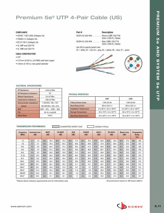
www.siemon.com
PR
EM
IUM
5e
AN
D S
YS
TE
M 5
eU
TP
5.11
Premium 5e® UTP 4-Pair Cable (US)
COMPLIANCE
• ISO/IEC 11801:2002 (Category 5e)
• TIA568-C.2 (Category 5e)
• IEC 61156-5 (Category 5e)
• UL CMP and CSA FT6
• UL CMR and CSA FT4
CABLE CONSTRUCTION
• UTP
• 0.51mm (0.020 in.) (24 AWG) solid bare copper
• 4.9mm (0.194 in.) max jacket diameter
*Values above industry requirements are for information only
Frequency Insertion Loss NEXT PS NEXT ACR PSACR ACR-F PS ACR-F Return Loss Propagation(MHz) (dB) (dB) (dB) (dB) (dB) (dB) (dB) (dB) Delay
(ns)
1.0 2.1 1.9 68.3 79.3 66.3 72.3 66.2 77.4 64.2 70.4 67.8 84.8 65.8 78.8 20.0 27.0 550 5454.0 4.1 3.7 59.3 70.3 57.3 63.3 55.2 66.6 53.2 59.6 55.7 72.8 53.7 66.8 23.3 32.0 532 527
10.0 6.5 5.8 53.3 64.3 51.3 57.3 46.9 58.5 44.9 51.5 47.8 64.8 45.8 58.8 25.5 32.0 525 52016.0 8.2 7.4 50.3 61.2 48.3 54.2 42.1 53.8 40.1 46.8 43.7 60.7 41.7 54.7 25.5 32.0 523 51820.0 9.2 8.3 48.8 59.8 46.8 52.8 39.6 51.5 37.6 44.5 41.7 58.8 39.7 52.8 25.5 32.0 522 51731.25 11.5 10.5 45.9 56.9 43.9 49.9 34.4 46.4 32.4 39.4 37.9 54.9 35.9 48.9 24.4 30.0 520 51562.5 16.4 15.0 41.4 52.4 39.4 45.4 24.9 37.4 22.9 30.4 31.8 48.9 29.8 42.9 22.7 30.0 519 514
100.0 21.0 19.3 38.3 49.3 36.3 42.3 17.3 30.0 15.3 23.0 27.8 44.8 25.8 38.8 21.5 30.0 518 513160.0* 26.8 25.1 35.3 46.2 33.3 39.2 8.4 21.1 6.4 14.1 23.7 40.7 21.7 34.7 20.4 28.0 517 512200.0* 30.2 28.1 33.8 44.8 31.8 37.8 3.6 16.7 1.6 9.7 21.7 38.8 19.7 32.8 19.8 27.0 517 512250.0* 34.0 31.4 32.3 43.3 30.3 36.3 -1.6 11.9 -3.6 4.9 19.8 36.8 17.8 30.8 19.2 26.0 516 511300.00* 37.4 34.5 31.2 42.1 29.2 35.1 -6.3 7.6 -8.3 0.6 18.2 35.3 16.2 29.3 18.8 25.0 516 511350.0* 40.7 39.4 30.2 41.1 28.2 34.1 -10.5 1.7 -12.5 -5.3 16.9 33.9 14.9 27.9 18.4 24.0 516 511
TRANSMISSION PERFORMANCE GUARANTEED WORST CASE SIEMON TYPICAL
All performance based on 100 meters (328 ft.).
Part # Description9C5P4-E2-(XX)-RXA . . . . . . . . . Plenum (CMP, CSA FT6)
305m (1000 ft.), Reelex
9C5R4-E2-(XX)-RXA . . . . . . . . . Riser (CMR, CSA FT4) 305m (1000 ft.), Reelex
Use (XX) to specify jacket color: 02 = white, 03 = red, 04 = gray, 05 = yellow, 06 = blue, 07 = green
CMP CMR
Pulling Tension (max) 110N (25 lbf) 110N (25 lbf)
Bend Radius (min) 20mm (0.8 in.) 20mm (0.8 in.)
Installation Temperature 0 to 60°C (+32 to 140°F) 0 to 60°C (+32 to 140°F)
Storage Temperature -20 to 75°C (-4 to 167°F) -20 to 75°C (-4 to 167°F)
Operating Temperature -20 to 60°C (-4 to 140°F) -20 to 60°C (-4 to 140°F)
PHYSICAL PROPERTIES
DC Resistance <9.38 Ω/100m
DC Resistance Unbalance 5%
Mutual Capacitance 5.6 nF/100m
Capacitance Unbalance <330 pF/100m
Characteristic Impedance 1-100 MHz: 100 ± 15%
(ohms) 100-350 MHz: 100 ± 22%
NVP CMP—70% CMR— 68%
TCL 40-10 x log(f)dB
Delay Skew ≤35ns
ELECTRICAL SPECIFICATIONS
05_Premium_Sys_5E_UTP.qxd:ZMax_Catalog 1/8/10 9:13 AM Page 12

PR
EM
IUM
5e
AN
D S
YS
TE
M 5
eU
TP
5.12 www.siemon.com
Premium 5e® UTP 4-Pair Cable(International)
COMPLIANCE
• ISO/IEC 11801:2002 (Category 5e)
• TIA-568-C.3 (Category 5e)
• IEC 61156-5:2002 (Category 5e)
• UL CM: IEC 60332-1
• UL CMR and CSA FT4
• LS0H: IEC 60332-1, IEC 60754 and IEC 61034
CABLE CONSTRUCTION
• UTP
• 0.5mm (0.02 in.) (24 AWG) solid bare copper
• 5.5mm (0.22 in.) max jacket diameter
*Values above industry requirements are for information only All performance based on 100 meters (328 ft.).
Part # Description9C5M4-E2. . . . . . . . . . . . . . . . . PVC (CM, IEC 60332-1), Gray Jacket,
305m (1000 ft.), Reelex
9C5R4-E2 . . . . . . . . . . . . . . . . . PVC (CMR, CSA FT4, Riser), Blue Jacket, 305m (1000 ft.), Reelex
9C5L4-E2 . . . . . . . . . . . . . . . . . LS0H (IEC 60332-1), Violet Jacket, 305m (1000 ft.) Reelex
LS0H CM/CMR
Pulling Tension (max) 110N (25 lbf) 110N (25 lbf)
Bend Radius (min) 22mm (0.9 in.) 25mm (0.9 in.)
Installation Temperature 0 to 60°C (+32 to 140°F) 0 to 60°C (+32 to 140°F)
Storage Temperature -20 to 75°C (-4 to 167°F) -20 to 75°C (-4 to 167°F)
Operating Temperature -20 to 60°C (-4 to 140°F) -20 to 60°C (-4 to 140°F)
PHYSICAL PROPERTIES
TRANSMISSION PERFORMANCE TIA & ISO/IEC SIEMON TYPICAL
Frequency Insertion Loss NEXT PS NEXT ACR PSACR ACR-F PS ACR-F Return Loss Propagation(MHz) (dB) (dB)* (dB) (dB) (dB) (dB) (dB) (dB) Delay
(ns)
1.0 2.1 1.9 65.3 79.3 62.3 72.3 63.2 77.4 60.2 70.4 63.8 84.8 60.8 78.8 20.0 27.0 570 545
4.0 4.1 3.7 56.3 70.0 53.3 63.3 52.2 66.6 49.2 59.6 51.8 72.8 48.8 66.8 23.0 32.0 552 527
10.0 6.5 5.8 50.3 64.3 47.3 57.3 43.8 58.5 40.8 51.5 43.8 64.8 40.8 58.8 25.0 32.0 545 520
16.0 8.3 7.4 47.2 61.2 44.2 54.2 39.0 53.8 36.0 46.8 39.7 60.7 36.7 54.7 25.0 32.0 543 518
20.0 9.3 8.3 45.8 59.8 42.8 52.8 36.5 51.5 33.5 44.5 37.8 58.8 34.8 52.8 25.0 32.0 542 517
31.25 11.7 10.5 42.9 56.9 39.9 49.9 31.1 46.4 28.1 39.4 33.9 54.9 30.9 48.9 23.6 30.0 540 515
62.5 17.0 15.0 38.4 52.4 35.4 45.4 21.4 37.4 18.4 30.4 27.9 48.9 24.9 42.9 21.5 30.0 539 514
100.0 22.0 19.3 35.3 49.3 32.3 42.3 13.3 30.0 10.3 23.0 23.8 44.8 20.8 38.8 20.1 30.0 538 513
160.0* 28.6 25.1 32.2 46.2 29.2 39.2 3.7 21.1 0.7 14.1 19.7 40.7 16.7 34.7 18.7 28.0 537 512
200.0* 32.4 28.1 30.8 44.8 27.8 37.8 -1.6 16.7 -4.6 9.7 17.8 38.8 14.8 32.8 18.0 27.0 537 512
250.0* 36.9 31.4 29.3 43.3 26.3 36.3 -7.5 11.9 -10.5 4.9 15.8 36.8 12.8 30.8 17.3 26.0 536 511
300.0* 41.0 34.5 28.1 42.1 25.1 35.1 -12.8 7.6 -15.8 0.6 14.3 35.3 11.3 29.3 16.8 25.0 536 511
350.0* 44.9 39.4 27.1 41.1 24.1 34.1 -17.7 1.7 -20.7 -5.3 12.9 33.9 9.9 27.9 16.3 24.0 536 511
DC Resistance <9.38 Ω/100m
DC Resistance Unbalance 5%
Mutual Capacitance 5.6 nF/100m
Capacitance Unbalance <330 pF/100m
Characteristic Impedance 1-100 MHz: 100 ± 15%
(ohms) 100-350 MHz: 100 ± 22%
NVP 70%
TCL 40-10 x log(f)dB
Delay Skew ≤40ns
ELECTRICAL SPECIFICATIONS
05_Premium_Sys_5E_UTP.qxd:ZMax_Catalog 1/8/10 9:13 AM Page 13

www.siemon.com
PR
EM
IUM
5e
AN
D S
YS
TE
M 5
eU
TP
5.13
05_Premium_Sys_5E_UTP.qxd:ZMax_Catalog 1/8/10 9:13 AM Page 14
FIB
ER
6.0 www.siemon.com
Siemon’s XGLO® 50/125 multimode and singlemode fiber optic cabling systems are designed to provide network users with the capacity to support up to and beyond 10 Gb/sdata throughput. Supported by LC and SC style connecting hardware, XGLO solutions areideal for high-speed LAN backbones, storage area networks (SAN) and fiber-to-the-desktop.
LightSystem® is a complete end-to-end multimode fiber optic solution that is ideal forcompanies that do not require a 10 gigabit system, but still need a high-performance system that can support 1 Gigabit Ethernet applications.
Combining cutting edge performance with high speed installation, Siemon’s Plug andPlay Fiber Optic Cabling System was designed from the ground up to satisfy the needsof high-performance data centers.
These systems offer comprehensive horizontal and backbone fiber cabling solutions.
SECTION CONTENTS
Plug and Play Modules . . . . . . . . . . . . . . . . . . . . . . . . . . . . . . . . . . . . 6.1
MTP Adapter Plates . . . . . . . . . . . . . . . . . . . . . . . . . . . . . . . . . . . . . . . 6.1
MTP to MTP Reels . . . . . . . . . . . . . . . . . . . . . . . . . . . . . . . . . . . . . . . . 6.2
MTP to MTP Extenders . . . . . . . . . . . . . . . . . . . . . . . . . . . . . . . . . . . . 6.3
MTP to LC Trunks . . . . . . . . . . . . . . . . . . . . . . . . . . . . . . . . . . . . . . . . 6.3
MTP to LC Hydras . . . . . . . . . . . . . . . . . . . . . . . . . . . . . . . . . . . . . . . . 6.4
XGLO® Jumpers and Pigtails . . . . . . . . . . . . . . . . . . . . . . . . . . . . . . . . 6.5
LightSystem® Jumpers and Pigtails . . . . . . . . . . . . . . . . . . . . . . . . . . .6.6
ValuLight™ Jumpers and Pigtails . . . . . . . . . . . . . . . . . . . . . . . . . . . . .6.7
XLR8 . . . . . . . . . . . . . . . . . . . . . . . . . . . . . . . . . . . . . . . . . . . . . . . . . .6.8
XLR8 Pre-Polished Connectors . . . . . . . . . . . . . . . . . . . . . . . . . . . . . . .6.9
SC and ST Epoxy Polish Connectors . . . . . . . . . . . . . . . . . . . . . . . . . .6.10
LC Epoxy Polish Connectors . . . . . . . . . . . . . . . . . . . . . . . . . . . . . . . .6.11
LightSpeed® ST, SC Fiber Termination Kit . . . . . . . . . . . . . . . . . . . . . 6.11
LC Fiber Termination Upgrade Kit . . . . . . . . . . . . . . . . . . . . . . . . . . . 6.11
LightSpeed Fiber Consumables Kit . . . . . . . . . . . . . . . . . . . . . . . . . . 6.12
Replacement Tools for Fiber Termination Kits . . . . . . . . . . . . . . . . . . . 6.12
Fiber Trunking Cable Assemblies . . . . . . . . . . . . . . . . . . . . . . .6.13 –6.15
XGLO Fiber Optic Cable (US) . . . . . . . . . . . . . . . . . . . . . . . . . . . . . . . .6.16
XGLO Fiber Optic Cable (International) . . . . . . . . . . . . . . . . . . .6.18 – 6.19
LightSystem Fiber Optic Cable (US) . . . . . . . . . . . . . . . . . . . . .6.20 – 6.21
LightSystem Fiber Optic Cable (International) . . . . . . . . . . . . .6.22 – 6.23
Aluminum Interlocking Armor Fiber Cable . . . . . . . . . . . . . . . . . . . . . .6.24
06_Fiber_Cble_Asmbly_RevB.qxd:ZMax_Catalog 2/12/10 3:28 PM Page 1
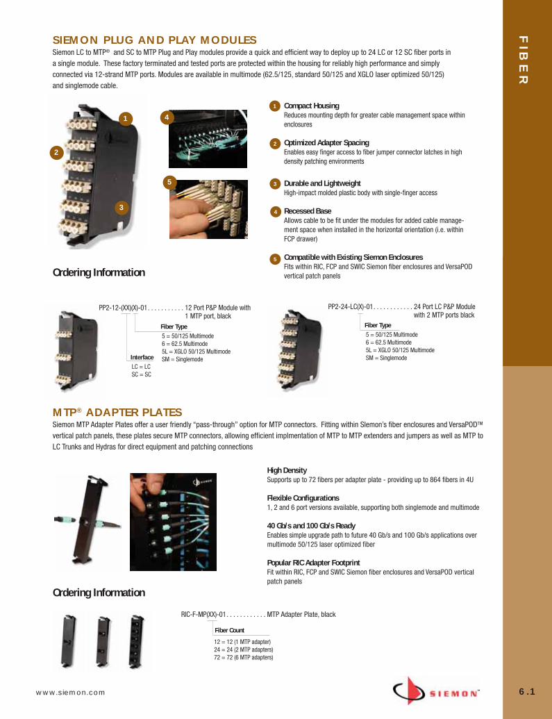
www.siemon.com
FIB
ER
6.1
SIEMON PLUG AND PLAY MODULESSiemon LC to MTP® and SC to MTP Plug and Play modules provide a quick and efficient way to deploy up to 24 LC or 12 SC fiber ports ina single module. These factory terminated and tested ports are protected within the housing for reliably high performance and simplyconnected via 12-strand MTP ports. Modules are available in multimode (62.5/125, standard 50/125 and XGLO laser optimized 50/125)and singlemode cable.
MTP® ADAPTER PLATESSiemon MTP Adapter Plates offer a user friendly “pass-through” option for MTP connectors. Fitting within SIemon’s fiber enclosures and VersaPODTM
vertical patch panels, these plates secure MTP connectors, allowing efficient implmentation of MTP to MTP extenders and jumpers as well as MTP toLC Trunks and Hydras for direct equipment and patching connections
Ordering Information
Ordering Information
PP2-12-(XX)(X)-01. . . . . . . . . . . 12 Port P&P Module with1 MTP port, black
InterfaceLC = LCSC = SC
Fiber Type5 = 50/125 Multimode6 = 62.5 Multimode5L = XGLO 50/125 MultimodeSM = Singlemode
PP2-24-LC(X)-01. . . . . . . . . . . . 24 Port LC P&P Modulewith 2 MTP ports black
Fiber Type5 = 50/125 Multimode6 = 62.5 Multimode5L = XGLO 50/125 MultimodeSM = Singlemode
Fiber Count
12 = 12 (1 MTP adapter)24 = 24 (2 MTP adapters)72 = 72 (6 MTP adapters)
Compact Housing Reduces mounting depth for greater cable management space withinenclosures
Optimized Adapter SpacingEnables easy finger access to fiber jumper connector latches in highdensity patching environments
Durable and LightweightHigh-impact molded plastic body with single-finger access
Recessed Base Allows cable to be fit under the modules for added cable manage-ment space when installed in the horizontal orientation (i.e. withinFCP drawer)
Compatible with Existing Siemon Enclosures Fits within RIC, FCP and SWIC Siemon fiber enclosures and VersaPOD vertical patch panels
High DensitySupports up to 72 fibers per adapter plate - providing up to 864 fibers in 4U
Flexible Configurations 1, 2 and 6 port versions available, supporting both singlemode and multimode
40 Gb/s and 100 Gb/s ReadyEnables simple upgrade path to future 40 Gb/s and 100 Gb/s applications overmultimode 50/125 laser optimized fiber
Popular RIC Adapter FootprintFit within RIC, FCP and SWIC Siemon fiber enclosures and VersaPOD verticalpatch panels
RIC-F-MP(XX)-01. . . . . . . . . . . . MTP Adapter Plate, black
1
1
2
3
5
4
2
3
4
5
06_Fiber_Cble_Asmbly_RevB.qxd:ZMax_Catalog 2/12/10 3:28 PM Page 2

FIB
ER
6.2 www.siemon.com
MTP® TO MTP REELSCombining Siemon’s reduced-diameter RazorCoreTM cable with 12-fiber MTP connectors, Plug and Play Reels are designed to be quicklypulled and connected to Siemon Plug and Play Modules and MTP Adapter Plates. Custom configurable to precise application requirements,these reels efficiently put high-performance, high-density fiber connections exactly where you need them.
Ordering Information
FR(XXX)-(XX)(X)(XXX)(X)-C. . . . . . . . . . . . .MTP-MTP reel, 12 fiber, all fiber types and jacket material, polarity method C per TIA-568-C.0
Fiber Count
12 = 1224 = 2436 = 3648 = 4872 = 7296 = 96144 = 144
Fiber Type5 = 50/125 Multimode6 = 62.5/125 Multimode5L = XGLO 50/125 MultimodeSM = Singlemode
Jacket RatingR =RiserP =PlenumL = LSOH
Length UnitF = FeetM = Meters
Custom ConfigurationsAvailable from 12 to 144 fiber counts inincrements of 12 fibers
Multiple Fiber TypesAvailable in multimode (62.5/125, standard50/125 and laser optimized 50/125) and sin-glemode. Jacket ratings in riser, plenum andLSOH
*Reduced Pathway FillSiemon's RazorCore cable has significantlyreduced cable O.D. resulting in less cabletray fill and pathway restrictions
Protective PackagingDual shelf reel keeps unprotected connectiv-ity away from harm during payout
40 Gb/s and 100 Gb/s ReadyEnables simple upgrade path to future 40 Gb/sand 100 Gb/s applications over multimode50/125 laser optimized fiber
Ordering Length
1 meter (3.3 ft) 1 meter (3.3 ft)
**Ordering length is measured connector tip to connector tip. Multi-legversions offered with standard 1 meter (3.3 ft) legs. Minimum orderlength is 3 meters (10 ft.).
* See page 6.3 for RazorCore cable diameters
Length**
Length must be 3 digitsExample: 003 = 3 m
010 = 10 ft
06_Fiber_Cble_Asmbly_RevB.qxd:ZMax_Catalog 2/12/10 3:28 PM Page 3

www.siemon.com
FIB
ER
6.3
Ordering Information
TF(X)(X)(XX)(X)(XX)LC(XXX)(X). . . . . . . . . . MTP - LC Trunk (distribution to breakout)
Fiber Count
B = 12C = 24E = 36F = 48G = 72H = 96J = 144
Pulling Eye
A = Side AB = Side BC = None
Jacket RatingR = RiserP = PlenumL = LSOH
MTP® TO MTP EXTENDERSConstructed with Siemon’s reduced-diameter RazorCoreTM cable, extenders offer Male MTP Connectors on oneend and female MTP on the other to allow field extension of MTP Reels. Available in 12-144 fiber versions aswell as multimode (standard 50/125, 62.5/125, XGLO 50/125) and singlemode fiber types.
Ordering Information
FE(XXX)-(XX)(X)(XXX)(X). . . . . . . .P&P extender, Male MTP to Female MTP
Fiber Count12 =1224 =2436 =3648 =4872 =7296 =96144 =144
Fiber Type5 = 50/125 Multimode6 = 62.5/125 Multimode5L = XGLO 50/125 MultimodeSM = Singlemode
Jacket RatingR =RiserP =PlenumL =LSOH
Length*
Length Unit
Length must be 3 digitsExample: 003 = 3 m
010 = 10 ft
Fiber Type5 = 50/125 Multimode6 = 62.5/125 Multimode5L = XGLO 50/125 MultimodeSM = Singlemode
Custom ConfigurationsAvailable from 12 to 144 fiber counts in increments of 12 fibers
Multiple Fiber TypesAvailable in mulitmode (62.5/125, standard 50/125 and laser optimized 50/125)and s inglemode. Jacket ratings in riser, plenum and LSOH
Protective PackagingDual shelf reel keeps connectivity protected during payout
Ordering Length
*Ordering length is measured connector tip to connectortip. Multi-leg versions offered with standard 1 meter(3.3 ft) legs. Minimum order length is 3 meters (10 ft).
1 meter (3.3 ft)
Ordering Length
*Ordering length is measured con-nector tip to connector tip. Jacketedduplex LC legs offered in standard 1 meter (3.3 ft) length. Miniumumorder length is 3 meters (10ft).
FemaleMale
MM = MaleMF = Female
MTP Connector Gender
Fiber Count 12 24 36 48 72 96 144
Cable Diameter inches [mm] 0.12 [3.0] 0.25 [6.4] 0.29 [7.3] 0.29 [7.3] 0.33 [8.4] 0.52 [13.2] 0.52 [13.2]
RazorCore Cable Diameter
MTP® TO LC TRUNKSUtilizing high quality Siemon RazorCore cable, MTP to LC Trunks offer a connectivity transition from 12-fiber MTP connectors to duplex LCconnectors. These may be implemented with Siemon’s MTP Adapter Plates to provide flexible direct MTP to LC patching options over awide a range of distances and infrastructure configurations.
F = FeetM = Meters
Length*
Length must be 3 digitsExample: 003 = 3 m
010 = 10 ft
Length Unit
F = FeetM = Meters
06_Fiber_Cble_Asmbly_RevB.qxd:ZMax_Catalog 2/12/10 3:28 PM Page 4
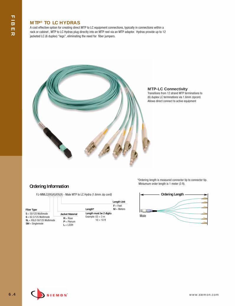
FIB
ER
6.4 www.siemon.com
Ordering Information
FJ-MMLC(XX)(X)(XX)(X) - Male MTP to LC Hydra (1.6mm zip cord)
Fiber Type5 = 50/125 Multimode6 = 62.5/125 Multimode5L = XGLO 50/125 MultimodeSM = Singlemode
Jacket Material
R = RiserP = PlenumL = LSOH
Length UnitF = FeetM = Meters
MTP-LC Connectivity Transitions from 12 strand MTP terminations to(6) duplex LC terminations via 1.6mm zipcord.Allows direct connect to active equipment
Ordering Length
*Ordering length is measured connector tip to connector tip. Miniumum order length is 1 meter (3 ft).
Male
MTP® TO LC HYDRASA cost effective option for creating direct MTP to LC equipment connections, typically in connections within arack or cabinet , MTP to LC Hydras plug directly into an MTP reel via an MTP adaptor. Hydras provide up to 12jacketed LC (6 duplex) “legs”, eliminating the need for fiber jumpers.
Length*
Length must be 2 digitsExample: 03 = 3 m
10 = 10 ft
06_Fiber_Cble_Asmbly_RevB.qxd:ZMax_Catalog 2/12/10 3:28 PM Page 5
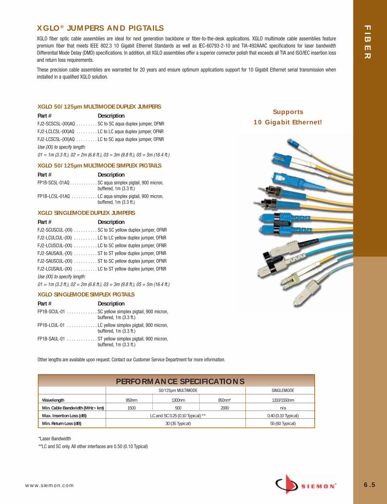
www.siemon.com
FIB
ER
6.5
*Laser Bandwidth
**LC and SC only. All other interfaces are 0.50 (0.10 Typical)
50/125µm MULTIMODE SINGLEMODE
Wavelength 850nm 1300nm 850nm* 1310/1550nm
Min. Cable Bandwidth (MHz • km) 1500 500 2000 n/a
Max. Insertion Loss (dB) LC and SC 0.25 (0.10 Typical) ** 0.40 (0.10 Typical)
Min. Return Loss (dB) 30 (35 Typical) 55 (60 Typical)
XGLO® JUMPERS AND PIGTAILSXGLO fiber optic cable assemblies are ideal for next generation backbone or fiber-to-the-desk applications. XGLO multimode cable assemblies featurepremium fiber that meets IEEE 802.3 10 Gigabit Ethernet Standards as well as IEC-60793-2-10 and TIA-492AAAC specifications for laser bandwidthDifferential Mode Delay (DMD) specifications. In addition, all XGLO assemblies offer a superior connector polish that exceeds all TIA and ISO/IEC insertion lossand return loss requirements.
These precision cable assemblies are warranted for 20 years and ensure optimum applications support for 10 Gigabit Ethernet serial transmission wheninstalled in a qualified XGLO solution.
XGLO 50/125µm MULTIMODE DUPLEX JUMPERSPart # DescriptionFJ2-SCSC5L-(XX)AQ . . . . . . . . . SC to SC aqua duplex jumper, OFNR
FJ2-LCLC5L-(XX)AQ . . . . . . . . . LC to LC aqua duplex jumper, OFNR
FJ2-LCSC5L-(XX)AQ . . . . . . . . . LC to SC aqua duplex jumper, OFNR
Use (XX) to specify length:
01 = 1m (3.3 ft.), 02 = 2m (6.6 ft.), 03 = 3m (9.8 ft.), 05 = 5m (16.4 ft.)
XGLO 50/125µm MULTIMODE SIMPLEX PIGTAILSPart # DescriptionFP1B-SC5L-01AQ . . . . . . . . . . . . SC aqua simplex pigtail, 900 micron,
buffered, 1m (3.3 ft.)
FP1B-LC5L-01AQ . . . . . . . . . . . LC aqua simplex pigtail, 900 micron, buffered, 1m (3.3 ft.)
XGLO SINGLEMODE DUPLEX JUMPERSPart # DescriptionFJ2-SCUSCUL-(XX) . . . . . . . . . . SC to SC yellow duplex jumper, OFNR
FJ2-LCULCUL-(XX) . . . . . . . . . . LC to LC yellow duplex jumper, OFNR
FJ2-LCUSCUL-(XX) . . . . . . . . . . LC to SC yellow duplex jumper, OFNR
FJ2-SAUSAUL-(XX) . . . . . . . . . . ST to ST yellow duplex jumper, OFNR
FJ2-SAUSCUL-(XX) . . . . . . . . . . ST to SC yellow duplex jumper, OFNR
FJ2-LCUSAUL-(XX) . . . . . . . . . . LC to ST yellow duplex jumper, OFNR
Use (XX) to specify length:
01 = 1m (3.3 ft.), 02 = 2m (6.6 ft.), 03 = 3m (9.8 ft.), 05 = 5m (16.4 ft.)
XGLO SINGLEMODE SIMPLEX PIGTAILSPart # DescriptionFP1B-SCUL-01 . . . . . . . . . . . . . SC yellow simplex pigtail, 900 micron,
buffered, 1m (3.3 ft.)
FP1B-LCUL-01 . . . . . . . . . . . . . LC yellow simplex pigtail, 900 micron,buffered, 1m (3.3 ft.)
FP1B-SAUL-01 . . . . . . . . . . . . . ST yellow simplex pigtail, 900 micron,buffered, 1m (3.3 ft.)
Other lengths are available upon request. Contact our Customer Service Department for more information.
Supports10 Gigabit Ethernet!
PERFORMANCE SPECIFICATIONS
06_Fiber_Cble_Asmbly_RevB.qxd:ZMax_Catalog 2/12/10 3:28 PM Page 6
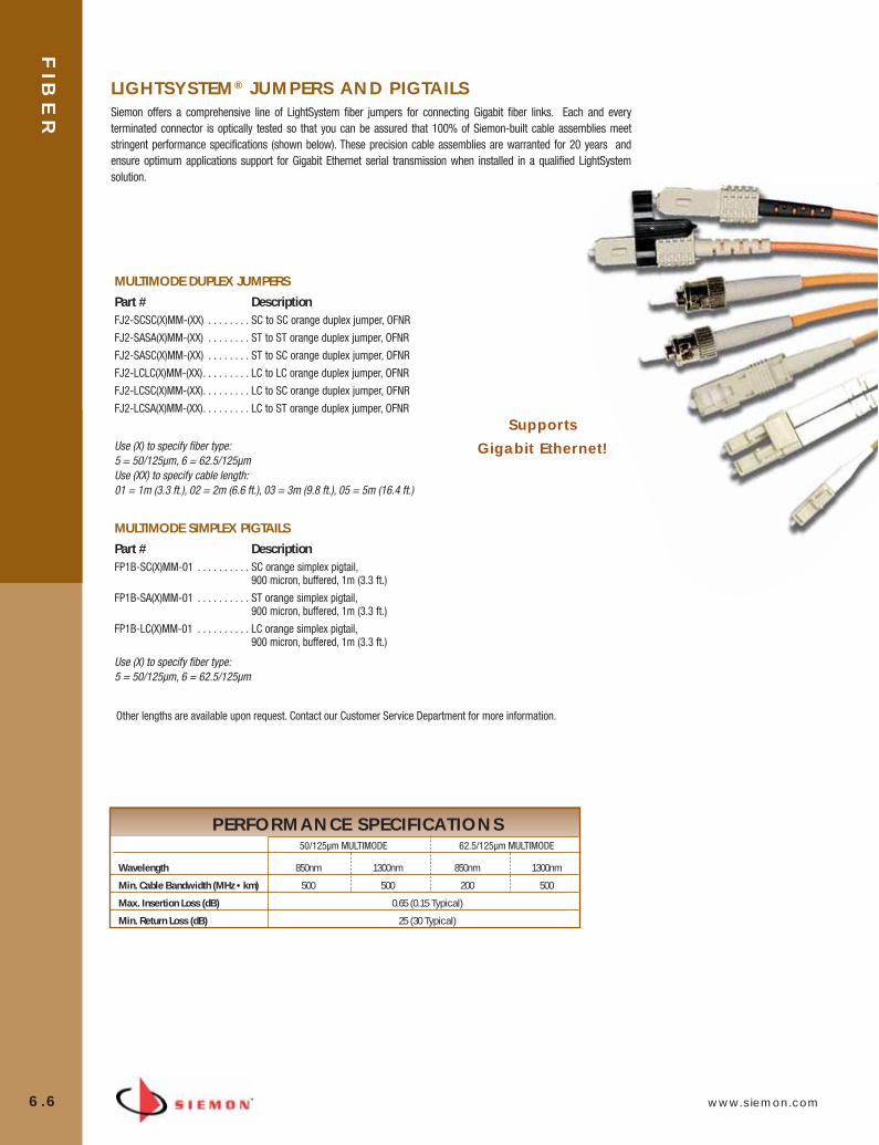
FIB
ER
6.6 www.siemon.com
50/125µm MULTIMODE 62.5/125µm MULTIMODE
Wavelength 850nm 1300nm 850nm 1300nm
Min. Cable Bandwidth (MHz • km) 500 500 200 500
Max. Insertion Loss (dB) 0.65 (0.15 Typical)
Min. Return Loss (dB) 25 (30 Typical)
Other lengths are available upon request. Contact our Customer Service Department for more information.
MULTIMODE DUPLEX JUMPERSPart # DescriptionFJ2-SCSC(X)MM-(XX) . . . . . . . . SC to SC orange duplex jumper, OFNR
FJ2-SASA(X)MM-(XX) . . . . . . . . ST to ST orange duplex jumper, OFNR
FJ2-SASC(X)MM-(XX) . . . . . . . . ST to SC orange duplex jumper, OFNR
FJ2-LCLC(X)MM-(XX). . . . . . . . . LC to LC orange duplex jumper, OFNR
FJ2-LCSC(X)MM-(XX). . . . . . . . . LC to SC orange duplex jumper, OFNR
FJ2-LCSA(X)MM-(XX). . . . . . . . . LC to ST orange duplex jumper, OFNR
Use (X) to specify fiber type: 5 = 50/125µm, 6 = 62.5/125µm Use (XX) to specify cable length: 01 = 1m (3.3 ft.), 02 = 2m (6.6 ft.), 03 = 3m (9.8 ft.), 05 = 5m (16.4 ft.)
MULTIMODE SIMPLEX PIGTAILSPart # DescriptionFP1B-SC(X)MM-01 . . . . . . . . . . SC orange simplex pigtail,
900 micron, buffered, 1m (3.3 ft.)
FP1B-SA(X)MM-01 . . . . . . . . . . ST orange simplex pigtail, 900 micron, buffered, 1m (3.3 ft.)
FP1B-LC(X)MM-01 . . . . . . . . . . LC orange simplex pigtail, 900 micron, buffered, 1m (3.3 ft.)
Use (X) to specify fiber type: 5 = 50/125µm, 6 = 62.5/125µm
LIGHTSYSTEM® JUMPERS AND PIGTAILSSiemon offers a comprehensive line of LightSystem fiber jumpers for connecting Gigabit fiber links. Each and everyterminated connector is optically tested so that you can be assured that 100% of Siemon-built cable assemblies meetstringent performance specifications (shown below). These precision cable assemblies are warranted for 20 years andensure optimum applications support for Gigabit Ethernet serial transmission when installed in a qualified LightSystemsolution.
PERFORMANCE SPECIFICATIONS
SupportsGigabit Ethernet!
06_Fiber_Cble_Asmbly_RevB.qxd:ZMax_Catalog 2/12/10 3:28 PM Page 7
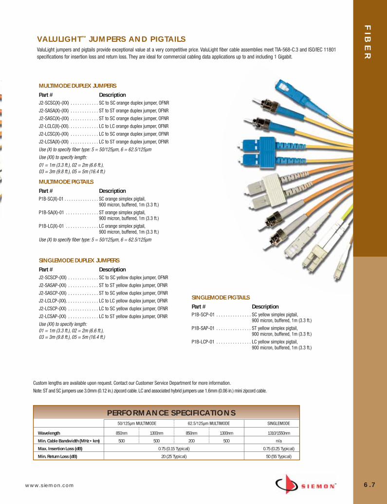
www.siemon.com
50/125µm MULTIMODE 62.5/125µm MULTIMODE SINGLEMODE
Wavelength 850nm 1300nm 850nm 1300nm 1310/1550nm
Min. Cable Bandwidth (MHz • km) 500 500 200 500 n/a
Max. Insertion Loss (dB) 0.75 (0.15 Typical) 0.75 (0.25 Typical)
Min. Return Loss (dB) 20 (25 Typical) 50 (55 Typical)
VALULIGHT™ JUMPERS AND PIGTAILSValuLight jumpers and pigtails provide exceptional value at a very competitive price. ValuLight fiber cable assemblies meet TIA-568-C.3 and ISO/IEC 11801specifications for insertion loss and return loss. They are ideal for commercial cabling data applications up to and including 1 Gigabit.
SINGLEMODE PIGTAILSPart # DescriptionP1B-SCP-01 . . . . . . . . . . . . . . . SC yellow simplex pigtail,
900 micron, buffered, 1m (3.3 ft.)
P1B-SAP-01 . . . . . . . . . . . . . . . ST yellow simplex pigtail, 900 micron, buffered, 1m (3.3 ft.)
P1B-LCP-01 . . . . . . . . . . . . . . . LC yellow simplex pigtail, 900 micron, buffered, 1m (3.3 ft.)
Custom lengths are available upon request. Contact our Customer Service Department for more information.
Note: ST and SC jumpers use 3.0mm (0.12 in.) zipcord cable. LC and associated hybrid jumpers use 1.6mm (0.06 in.) mini zipcord cable.
MULTIMODE DUPLEX JUMPERSPart # DescriptionJ2-SCSC(X)-(XX) . . . . . . . . . . . . SC to SC orange duplex jumper, OFNR
J2-SASA(X)-(XX) . . . . . . . . . . . . ST to ST orange duplex jumper, OFNR
J2-SASC(X)-(XX) . . . . . . . . . . . . ST to SC orange duplex jumper, OFNR
J2-LCLC(X)-(XX). . . . . . . . . . . . . LC to LC orange duplex jumper, OFNR
J2-LCSC(X)-(XX) . . . . . . . . . . . . LC to SC orange duplex jumper, OFNR
J2-LCSA(X)-(XX) . . . . . . . . . . . . LC to ST orange duplex jumper, OFNR
Use (X) to specify fiber type: 5 = 50/125µm, 6 = 62.5/125µm
Use (XX) to specify length:
01 = 1m (3.3 ft.), 02 = 2m (6.6 ft.), 03 = 3m (9.8 ft.), 05 = 5m (16.4 ft.)
MULTIMODE PIGTAILSPart # DescriptionP1B-SC(X)-01 . . . . . . . . . . . . . . . SC orange simplex pigtail,
900 micron, buffered, 1m (3.3 ft.)
P1B-SA(X)-01 . . . . . . . . . . . . . . ST orange simplex pigtail, 900 micron, buffered, 1m (3.3 ft.)
P1B-LC(X)-01 . . . . . . . . . . . . . . LC orange simplex pigtail, 900 micron, buffered, 1m (3.3 ft.)
Use (X) to specify fiber type: 5 = 50/125µm, 6 = 62.5/125µm
SINGLEMODE DUPLEX JUMPERSPart # DescriptionJ2-SCSCP-(XX) . . . . . . . . . . . . . SC to SC yellow duplex jumper, OFNR
J2-SASAP-(XX) . . . . . . . . . . . . . ST to ST yellow duplex jumper, OFNR
J2-SASCP-(XX) . . . . . . . . . . . . . ST to SC yellow duplex jumper, OFNR
J2-LCLCP-(XX). . . . . . . . . . . . . . LC to LC yellow duplex jumper, OFNR
J2-LCSCP-(XX) . . . . . . . . . . . . . LC to SC yellow duplex jumper, OFNR
J2-LCSAP-(XX) . . . . . . . . . . . . . LC to ST yellow duplex jumper, OFNR
Use (XX) to specify length: 01 = 1m (3.3 ft.), 02 = 2m (6.6 ft.), 03 = 3m (9.8 ft.), 05 = 5m (16.4 ft.)
FIB
ER
6.7
PERFORMANCE SPECIFICATIONS
06_Fiber_Cble_Asmbly_RevB.qxd:ZMax_Catalog 2/12/10 3:28 PM Page 8
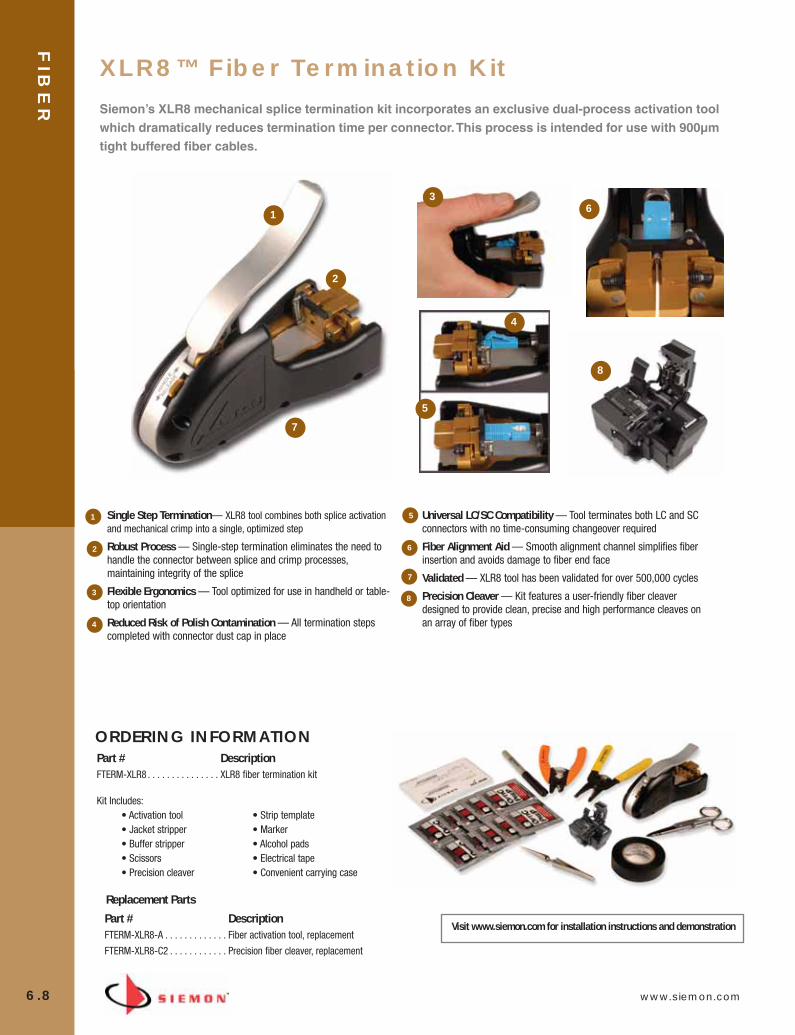
FIB
ER
6.8 www.siemon.com
Part # DescriptionFTERM-XLR8-A . . . . . . . . . . . . . Fiber activation tool, replacement
FTERM-XLR8-C2 . . . . . . . . . . . . Precision fiber cleaver, replacement
ORDERING INFORMATIONPart # DescriptionFTERM-XLR8 . . . . . . . . . . . . . . . XLR8 fiber termination kit
Replacement Parts
Kit Includes:• Activation tool• Jacket stripper• Buffer stripper• Scissors• Precision cleaver
• Strip template• Marker• Alcohol pads• Electrical tape• Convenient carrying case
Visit www.siemon.com for installation instructions and demonstration
XLR8™ Fiber Termination Kit
Siemon’s XLR8 mechanical splice termination kit incorporates an exclusive dual-process activation toolwhich dramatically reduces termination time per connector. This process is intended for use with 900µmtight buffered fiber cables.
Single Step Termination— XLR8 tool combines both splice activationand mechanical crimp into a single, optimized step
Robust Process — Single-step termination eliminates the need tohandle the connector between splice and crimp processes,maintaining integrity of the splice
Flexible Ergonomics — Tool optimized for use in handheld or table-top orientation
Reduced Risk of Polish Contamination — All termination stepscompleted with connector dust cap in place
Universal LC/SC Compatibility — Tool terminates both LC and SCconnectors with no time-consuming changeover required
Fiber Alignment Aid — Smooth alignment channel simplifies fiberinsertion and avoids damage to fiber end face
Validated — XLR8 tool has been validated for over 500,000 cycles
Precision Cleaver — Kit features a user-friendly fiber cleaverdesigned to provide clean, precise and high performance cleaves on an array of fiber types
1
2
3
4
5
6
7
8
1
4
5
3
2
6
7
8
06_Fiber_Cble_Asmbly_RevB.qxd:ZMax_Catalog 2/12/10 3:29 PM Page 9

www.siemon.com
FIB
ER
6.9
XLR8™ Pre-Polished Connectors
Combined with the patent-pending XLR8 activation tool, Siemon’s new pre-polished XLR8 mechanicalsplice connectors can be deployed with unsurpassed termination speed and quality. Available in both LCand SC configurations, these connectors support both the multimode and singlemode versions ofSiemon’s 10 Gb/s XGLO® and Gigabit LightSystem® solutions.
Fewer Termination Steps —XLR8 SC connectors ship factory-assembled, eliminating time-consumingfield assembly of inner and outer connector bodies
Enhanced Splice Integrity — XLR8 connector termination process combines splicing and crimping in asingle step, eliminating connector handling that can impact splice integrity
Robust Polish Protection —Entire connector termination process is completed with dust-cap in place,protecting the critical end face polish from contamination
High Quality Performance — Exceeds TIA standards for optical peformance and fiber retention strength
Optical Performance
Insertion Loss
• SM: 0.20dB Typ
• MM: 0.20dB Typ
Return Loss
• SM: -55dB Typ
• MM: -37dB Typ
* For use with 900µm tight buffer terminations only - Fan-out kits to transition from 250µm to 900µm can not be used with XLR8 connectivity.
ORDERING INFORMATIONPart # DescriptionLC Multimode
FC1M-LC-5L-B12 . . . . . . . . . . . LC Simplex connector, 50/125µm laser optimized, 900µm buffered fiber*, aqua boot (XGLO)
FC1M-LC-6MM-B80 . . . . . . . . . LC Simplex connector, 62.5/125µm multimode, 900µm buffered fiber*, beige boot (LightSystem)
FC1M-LC-5MM-B01 . . . . . . . . . LC Simplex connector, 50/125µm multimode, 900µm buffered fiber*, black boot (LightSystem)
LC Singlemode
FC1M-LC-SM-B06. . . . . . . . . . . LC Simplex connector, singlemode, 900µm buffered fiber*, blue boot (XGLO and LightSystem)
SC Multimode
FC1M-SC-5L-B12 . . . . . . . . . . . SC Simplex connector, 50/125µm laser optimized, 900µm buffered fiber*, aqua boot (XGLO)
FC1M-SC-6MM-B80 . . . . . . . . . SC Simplex connector, 62.5/125µm multimode, 900µm buffered fiber*, beige boot (LightSystem)
FC1M-SC-5MM-B01 . . . . . . . . . SC Simplex connector, 50/125µm multimode, 900µm buffered fiber*, black boot (LightSystem)
SC Singlemode
FC1M-SC-SM-B06 . . . . . . . . . . SC Simplex connector, singlemode, 900µm buffered fiber*, blue boot (XGLO and LightSystem)
06_Fiber_Cble_Asmbly_RevB.qxd:ZMax_Catalog 2/12/10 3:29 PM Page 10

FIB
ER
6.10 www.siemon.com
SC AND ST EPOXY POLISH CONNECTORSSC EPOXY POLISH CONNECTORS
SC duplex connectors have a duplexing clip, which allows each connector to be removed individually. In the event fiber polarity is reversed duringtermination, there’s no need to discard the connector. Simply remove connectors from the clip and switch to correct the mistake, saving valuableinstallation time and money. The duplexing clip also speeds troubleshooting. In the event there’s a fault with a single connection, an individual connectorcan be removed from the clip and re-terminated without disturbing the adjacent connector.
SC connectors employ an outer housing that is color-coded in accordance with TIA/EIA-568-B.3 and ISO/IEC 11801 Ed. 2.0 requirements (beige formultimode and blue for singlemode).
MULTIMODE (XGLO® and LightSystem®)Part # DescriptionFC1-SC-MM-J80. . . . . . . . . . . . SC simplex connector, jacketed fiber, beige boot
FC1-SC-MM-B80. . . . . . . . . . . . SC simplex connector, buffered fiber, beige boot
FC2-SC-MM-B80. . . . . . . . . . . . SC duplex connector, buffered fiber, two beige boots
FC2-SC-MM-J . . . . . . . . . . . . . . SC duplex connector, jacketed fiber, one black boot and one beige boot
Add “-B” to the end of part number for bulk pack (Simplex: 100/box, Duplex: 50/box).
SINGLEMODE (XGLO)Part # DescriptionFC1-SC-SM-B06 . . . . . . . . . . . . SC simplex connector, buffered fiber, blue boot
FC1-SC-SM-J06 . . . . . . . . . . . . SC simplex connector, jacketed fiber, blue boot
FC2-SC-SM-B06 . . . . . . . . . . . . SC duplex connector, buffered fiber, two blue boots
FC2-SC-SM-J06 . . . . . . . . . . . . SC duplex connector, jacketed fiber, blue boot
Add “-B” to the end of part number for bulk pack (Simplex: 100/box, Duplex: 50/box).
ST EPOXY POLISH CONNECTORS
The ST connector employs a rugged metal bayonet coupling ring with radial ramps which facilitate engagement to the studs of the mating adapter. Two ST connectors are available for jacketed fiber, one with a beige boot and one with a black boot. The two colors enable easy identification of thefibers when terminating individual connectors to form a duplex jumper.
MULTIMODE (XGLO and LightSystem)
Part # Description FC1-SA-MM-J80 . . . . . . . . . . . . ST simplex connector, jacketed fiber, beige boot
FC1-SA-MM-B80. . . . . . . . . . . . ST simplex connector, buffered fiber, beige boot
Add “-B” to the end of part number for bulk pack (100/box).
SINGLEMODE (XGLO)
Part # DescriptionFC1-SA-SM-J06 . . . . . . . . . . . . ST simplex connector, jacketed fiber, blue boot
FC1-SA-SM-B06 . . . . . . . . . . . . ST simplex connector, buffered fiber, blue boot
Add “-B” to the end of part number for bulk pack (100/box).
Duplex
Simplex
Buffered
Jacketed
06_Fiber_Cble_Asmbly_RevB.qxd:ZMax_Catalog 2/12/10 3:29 PM Page 11

www.siemon.com
FIB
ER
6.11
LC FIBER TERMINATION LIGHTSPEED UPGRADE KITThe Siemon LC upgrade kit is used in conjunction with the LightSpeed Termination Kit (FTERM-L2)and has all the accessories to terminate LC connectors using Siemon’s exclusive LightSpeedadhesive. The kit includes an LC microscope head (that attaches to the microscope included withthe FTERM-L2), an LC polishing puck and a micro-torch* (to shrink the color-coded LC crimpsleeve tubing).
Part # DescriptionFTERM-LC . . . . . . . . . . . . . . . . . LC Fiber Termination Upgrade Kit
(used in conjunction with FTERM-L2)
Note: Contents of FTERM-LC are also available individually.
Contact our Customer Service Department for more information.
*Butane fuel not included.
LIGHTSPEED® ST, SC FIBER TERMINATION KITAchieve faster fiber terminations and higher performance with Siemon’s LightSpeed TerminationKit. The Siemon fiber termination kit contains all the tools required for termination of multimode orsinglemode ST or SC connectors — packaged in a rugged canvas carrying case. Use the optionalLC Upgrade Kit (see below) for LC connector terminations. All consumables must be orderedseparately as noted below.*
Part # DescriptionFTERM-L2 . . . . . . . . . . . . . . . . . LightSpeed Fiber Termination Kit for ST and SC multimode
connectors*
Note: Select tools and other termination products supplied with the kit can be ordered separately.*All consumables including primer, adhesive and polishing films are contained in the consumables kitand must be ordered separately.
LC EPOXY POLISH CONNECTORS (XGLO® & LIGHTSYSTEM®)
Siemon LC products offer all the benefits of SC and ST connections in a Small Form Factor (SFF),high-density design. LC adapter products are compatible with our popular MAX®, CT, FOB, andMX-SM work area and telecommunications room products, providing a wide variety of installationoptions. LC connectors take just two minutes to terminate, using the Siemon LightSpeed®
Termination Kit.
MULTIMODE
Part # DescriptionFC1-LC-MM-B80. . . . . . . . . . . . LC simplex connector, beige, multimode, buffered fiber, beige boot
FC2-LC-MM-J80 . . . . . . . . . . . . LC duplex connector, beige, multimode, jacketed fiber, beige boots
SINGLEMODE
Part # DescriptionFC1-LC-SM-B02 . . . . . . . . . . . . LC simplex connector, blue, singlemode, buffered fiber, white boot
FC1-LC-SM-J02 . . . . . . . . . . . . LC simplex connector, blue, singlemode, jacketed fiber, white boot
06_Fiber_Cble_Asmbly_RevB.qxd:ZMax_Catalog 2/12/10 3:29 PM Page 12

FIB
ER
6.12 www.siemon.com
Part # DescriptionFT-MS400 . . . . . . . . . . . . . . . . . 400X power microscope
FT-SCRIBE . . . . . . . . . . . . . . . . . Double bladed fiber cleaver
CI-SCISSORS . . . . . . . . . . . . . . . Electrician scissors
FT-CRIMP . . . . . . . . . . . . . . . . . Crimp tool w/3-position die for ST/SC/LC
FT-PAD . . . . . . . . . . . . . . . . . . . 152.4mm (6 in.) x 152.4mm (6 in.) polishing pad
FT-PUCK . . . . . . . . . . . . . . . . . . SC/ST compatible polishing puck
FT-TMPL . . . . . . . . . . . . . . . . . . Template for SC/ST and LC connectors
FT-JSTRP . . . . . . . . . . . . . . . . . Jacket stripper
FT-BSTRP . . . . . . . . . . . . . . . . . Buffer stripper
FT-LCPUCK . . . . . . . . . . . . . . . . Duplex LC Polishing Puck
FT-MSLC2HEAD. . . . . . . . . . . . . Duplex LC Scope Adapter
*This product contains material with a time and temperature sensitive shelf life. Store between 40 – 100 degrees F (4.4 – 38.5°C) and verify expiration date marked on product prior to use
**This recovery film is optional and not included with the consumables kit.
LIGHTSPEED® FIBER CONSUMABLES KIT Siemon’s LightSpeed fiber terminations consumables kit features a premium abrasive film to polish ceramic ferrules and glass at the same level, at aconsistent rate. The films have been qualified to assure exceptional insertion and return loss results when used in accordance with our instructions.
Part # DescriptionFT-CKIT-L2*. . . . . . . . . . . . . . . . Consumables kit for use with fiber termination
kit (FTERM-L2). Includes enough consumablesto perform a minimum of 200 multimode orsinglemode terminations
Individual components may be ordered separately as replacements. Part numbers listed below.
FT-PRBOT-L. . . . . . . . . . . . . . . . Primer bottle (3.5mL)
FT-ADH-L*. . . . . . . . . . . . . . . . . Adhesive Syringe (5cc)
FT-ALPAD . . . . . . . . . . . . . . . . . Alcohol pads
FT-WIPES . . . . . . . . . . . . . . . . . Dry lint-free wipes
FT-SYRMTIP . . . . . . . . . . . . . . . Syringe tip needles w/covers
FT-PF12. . . . . . . . . . . . . . . . . . . 12µm air polish film, gray
FT-PF3. . . . . . . . . . . . . . . . . . . . 3µm polish film, pink
FT-PF1. . . . . . . . . . . . . . . . . . . . 1µm polish film, purple
FT-FF. . . . . . . . . . . . . . . . . . . . . Finishing film, white
FT-PF6** . . . . . . . . . . . . . . . . . . 6µm recovery film, bronze
REPLACEMENT TOOLS FOR FIBER TERMINATION KITSSiemon’s offers a full line of replacement tools in the event that a tool is lost or has used up its life expectancy. The tools availableare the exact tools provided in our fiber termination kits.
06_Fiber_Cble_Asmbly_RevB.qxd:ZMax_Catalog 2/12/10 3:29 PM Page 13
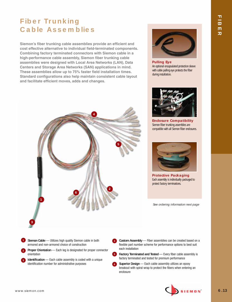
www.siemon.com
FIB
ER
6.13
Fiber Trunking Cable Assemblies
Siemon’s fiber trunking cable assemblies provide an efficient andcost effective alternative to individual field-terminated components.Combining factory terminated connectors with Siemon cable in ahigh-performance cable assembly, Siemon fiber trunking cable assemblies were designed with Local Area Networks (LAN), Data Centers and Storage Area Networks (SAN) applications in mind.These assemblies allow up to 75% faster field installation times. Standard configurations also help maintain consistent cable layoutand facilitate efficient moves, adds and changes.
1
2
3
4
5
6
Enclosure CompatibilitySiemon fiber trunking assemblies arecompatible with all Siemon fiber enclosures.
Protective PackagingEach assembly is individually packaged toprotect factory terminations.
Pulling EyeAn optional encapsulated protection sleevewith cable pulling eye protects the fiberduring installation.
Siemon Cable — Utilizes high quality Siemon cable in botharmored and non-armored choice of construction
Proper Orientation — Each leg is designated for proper connectororientation
Identification — Each cable assembly is coded with a uniqueidentification number for administrative purposes
Custom Assembly — Fiber assemblies can be created based on aflexible part number scheme for performance options to best suiteach installation
Factory Terminated and Tested — Every fiber cable assembly isfactory terminated and tested for premium performance
Superior Design — Each cable assembly utilizes an epoxybreakout with spiral wrap to protect the fibers when entering anenclosure
1 4
2
3
5
6
See ordering information next page
06_Fiber_Cble_Asmbly_RevB.qxd:ZMax_Catalog 2/12/10 3:29 PM Page 14
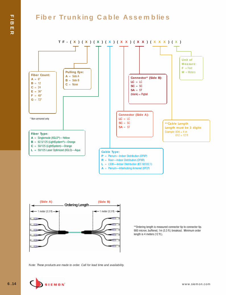
FIB
ER
6.14 www.siemon.com
Fiber Trunking Cable Assemblies
T F - ( X ) ( X ) ( X ) ( X ) ( X X ) ( X X ) ( X X X ) ( X )
Fiber Count:A = 6*B = 12C = 24E = 36*F = 48*G = 72*
Pulling Eye:A = Side AB = Side BC = None
Connector (Side A):LC = LC SC = SC SA = ST
Connector* (Side B):LC = LC SC = SC SA = ST (blank) = Pigtail
Unit of Measure:F = FeetM = Meters
Fiber Type:A = Singlemode (XGLO®)—Yellow B = 62.5/125 (LightSystem®)—OrangeC = 50/125 (LightSystem)—OrangeL = 50/125 Laser Optimized (XGLO)—Aqua Cable Type:
P = Plenum—Indoor Distribution (OFNP)R = Riser—Indoor Distribution (OFNR)L = LS0H—Indoor Distribution (IEC 60332.1)A = Plenum—Interlocking Armored (OFCP)
Note: These products are made to order. Call for lead time and availability.
Ordering Length
1 meter (3.3 ft) 1 meter (3.3 ft)
**Ordering length is measured connector tip to connector tip.900 micron, buffered, 1m (3.3 ft.) breakout. Minimum orderlength is 4 meters (12 ft.).
(Side A) (Side B)
* Non-armored only
**Cable LengthLength must be 3 digits Example: 004 = 4 m
012 = 12 ft
06_Fiber_Cble_Asmbly_RevB.qxd:ZMax_Catalog 2/12/10 3:29 PM Page 15

www.siemon.com
FIB
ER
6.15
Fiber Trunking Cable Assemblies
Fiber Type
62.5/125µm Multimode
50/125µm Multimode
50/125µm Laser Optimized
Singlemode
Max Insertion Loss (dB)
0.65 (0.15 Typical)
0.65 (0.15 Typical)
0.50 (0.10 Typical)
0.40 (0.25 Typical)
25 (30 Typical)
25 (30 Typical)
30 (35 Typical)
55 (57 Typical)
Min ReturnLoss (dB)
LightSystem
LightSystem
XGLO
XGLO
PerformanceClass
CONNECTORS — Optical Specifications
CONNECTORS — Physical Specifications
Connector Type IEC Intermateabilty TIA Intermateabilty Housing Color Boot Color Compliance Compliance SM MM SM MM
SC IEC 60874-14 TIA/EIA-604-3 Blue Beige Blue Beige
ST IEC 60874-10 TIA/EIA-604-2 N/A N/A Blue Beige
LC IEC 61754-20 TIA/EIA-604-10 Blue Beige White White
*XGLO singlemode fiber meets Low Water Peak specifications per ITU-T G.652.C/D
Cable Type
Non-Armored
Armored
Fiber Strand Count
612243648721224
44.5 (1.75)44.5 (1.75)44.5 (1.75)63.5 (2.5)63.5 (2.5)63.5 (2.5)
44.5 (1.75)44.5 (1.75)
Sleeve Diameter mm (in.)
15x cable diameter15x cable diameter15x cable diameter20x cable diameter20x cable diameter20x cable diameter15x cable diameter15x cable diameter
5.8 (0.23)5.8 (0.23)
13.7 (0.54)16.5 (0.65)16.0 (0.63)19.5 (0.77)13.0 (0.51)
14.8 (0.584)
70 (2.75)70 (2.75)70 (2.75)90 (3.5)90 (3.5)90 (3.5)90 (3.5)90 (3.5)
Required DuctDiameter mm (in.)
45.4 (100)45.4 (100)45.4 (100)45.4 (100)45.4 (100)45.4 (100)45.4 (100)45.4 (100)
Maximum PullForce
kg (Pounds)
CABLE DIAMETERS BY FIBER COUNT (ALL VALUES ARE NOMINAL)
Minimum Bend Radiusmm (in.)
Cable Diameter mm (in.)
CABLE — Optical and Physical Specifications
Multimode Singlemode
LightSystem® LightSystem XGLO®
Cable Type 62.5/125µm 50/125µm 50/125µm XGLO(850/1300 nm) (850/1300 nm) (850/1300 nm) (1310/1550 nm)
Fiber Cable Attenuation, Max (dB/km) 3.5/1.0 3.5/1.0 3.5/1.0 0.5/0.5*
OFL Bandwidth, min (MHz•km) 200/500 500/500 1500/500 N/A
Effective Modal Bandwidth, min (MHz•km) N/A N/A 2000/NS N/A
Cable Outer Jacket Color Orange Orange Aqua Yellow
Break-Out Colors: Single Fiber Strands** Blue, Orange, Green, Brown, Slate, White, Red, Black, Yellow, Violet, Rose, Aqua
Sub-Unit Colors and/or Markings** Blue, Orange, Green, Brown, Slate, White, Red, Black, Yellow, Violet, Rose, Aqua
Note: Because we are continously improving our products, Siemon reserves the right to change specifications and availability without prior notice
06_Fiber_Cble_Asmbly_RevB.qxd:ZMax_Catalog 2/12/10 3:29 PM Page 16

FIB
ER
6.16 www.siemon.com
SINGLEMODE, YELLOW JACKETPART # FIBER COUNT CONSTRUCTION9BB8(X)002B-E205A . . . . . . . . . . . . . . . . . 2 . . . . . . . . . . . . . . . . 1 tube of 2 fibers9BB8(X)004C-E205A . . . . . . . . . . . . . . . . . 4 . . . . . . . . . . . . . . . . 1 tube of 4 fibers9BB8(X)006D-E205A . . . . . . . . . . . . . . . . . 6 . . . . . . . . . . . . . . . . 1 tube of 6 fibers9BB8(X)008E-E205A. . . . . . . . . . . . . . . . . . 8 . . . . . . . . . . . . . . . . 1 tube of 8 fibers9BB8(X)012G-E205A. . . . . . . . . . . . . . . . . . 12 . . . . . . . . . . . . . . . 1 tube of 12 fibers9BB8(X)016C-E205A. . . . . . . . . . . . . . . . . . 16 . . . . . . . . . . . . . . . 4 tubes of 4 fibers9BB8(X)024L-E205A. . . . . . . . . . . . . . . . . . 24 . . . . . . . . . . . . . . . 1 tube of 24 fibers9BB8(X)036D-E205A . . . . . . . . . . . . . . . . . 36 . . . . . . . . . . . . . . . 6 tubes of 6 fibers9BB8(X)048G-E205A. . . . . . . . . . . . . . . . . . 48 . . . . . . . . . . . . . . 4 tubes of 12 fibers9BB8(X)072G-E205A. . . . . . . . . . . . . . . . . . 72 . . . . . . . . . . . . . . 6 tubes of 12 fibers
Use (X) to specify cable rating: R = OFNR, P = OFNP
50/125µm MULTIMODE LASER OPTIMIZED, AQUA JACKETPART # FIBER COUNT CONSTRUCTION9BB5(X)002B-T312A . . . . . . . . . . . . . . . . . 2 . . . . . . . . . . . . . . . . 1 tube of 2 fibers9BB5(X)004C-T312A . . . . . . . . . . . . . . . . . 4 . . . . . . . . . . . . . . . . 1 tube of 4 fibers9BB5(X)006D-T312A . . . . . . . . . . . . . . . . . 6 . . . . . . . . . . . . . . . . 1 tube of 6 fibers9BB5(X)008E-T312A. . . . . . . . . . . . . . . . . . 8 . . . . . . . . . . . . . . . . 1 tube of 8 fibers9BB5(X)012G-T312(Y). . . . . . . . . . . . . . . . . 12 . . . . . . . . . . . . . . . 1 tube of 12 fibers9BB5(X)016C-T312A. . . . . . . . . . . . . . . . . . 16 . . . . . . . . . . . . . . . 4 tubes of 4 fibers9BB5(X)024L-T312(Y) . . . . . . . . . . . . . . . . . 24 . . . . . . . . . . . . . . . 1 tube of 24 fibers9BB5(X)036D-T312A . . . . . . . . . . . . . . . . . 36 . . . . . . . . . . . . . . . 6 tubes of 6 fibers9BB5(X)048G-T312A. . . . . . . . . . . . . . . . . . 48 . . . . . . . . . . . . . . 4 tubes of 12 fibers9BB5(X)072G-T312A. . . . . . . . . . . . . . . . . . 72 . . . . . . . . . . . . . 6 tubes of 12 fibers
Use (X) to specify cable rating: R = OFNR, P = OFNPUse (Y) to specify reel length: 1 = 1000 ft. (305m) reel, A = Reel lengthgreater than 1000 ft. (305m)
12 Fiber Multimode
24 Fiber Multimode
12 Fiber Singlemode
24 Fiber Singlemode
6 FIBER 12 FIBER 24 FIBER 48 FIBER 72 FIBER
XGLO® 10 Gigabit Ethernet Fiber Optic Distribution Cable (US)
COMPLIANCE• ISO/IEC 11801:2002 (OM3) [MM]• ISO/IEC 11801:2002 (OS1) [SM]• TIA-568-C.3• TIA-598-C• IEC-60793-2-10 [MM]• TIA-492AAAC laser bandwidth DMD specification [MM]• IEC 60793-2-49 and TIA/EIA 455-220 DMD measurement test
procedures [MM]• ITU-T G.652.C [SM]• OFNR: Communications Type OFNR (UL) and CSA FT4 c(UL) • OFNP: Communications Type OFNP (UL) and CSA FT6 c(UL)
CABLE CONSTRUCTION • Tight buffer design reduces cable OD and pathway space
requirements• Flexible, lightweight for ease of installation• Thermoplastic outer and inner (sub-unit) jackets• Aramid yarn strength members• Dielectric central strength member• Color coded per TIA-598-C
06_Fiber_Cble_Asmbly_RevB.qxd:ZMax_Catalog 2/12/10 3:29 PM Page 17
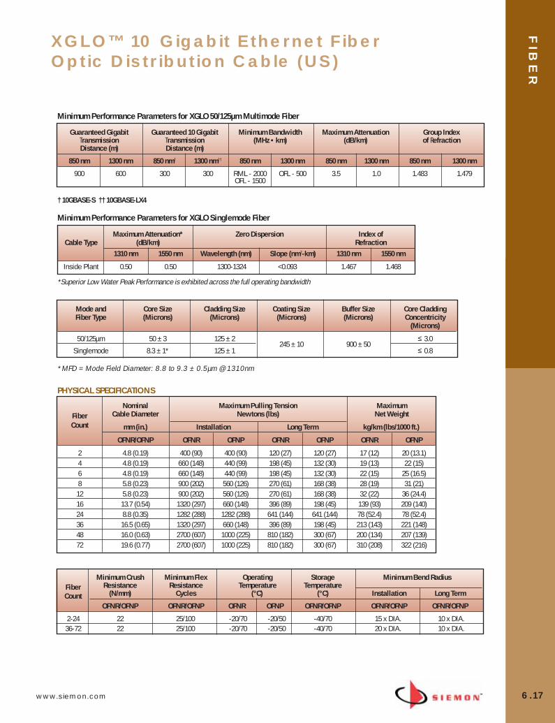
www.siemon.com
FIB
ER
6.17
XGLO™ 10 Gigabit Ethernet FiberOptic Distribution Cable (US)
*MFD = Mode Field Diameter: 8.8 to 9.3 ± 0.5µm @ 1310nm
Minimum Crush Minimum Flex Operating Storage Minimum Bend RadiusFiber Resistance Resistance Temperature TemperatureCount (N/mm) Cycles (°C) (°C) Installation Long Term
OFNR/OFNP OFNR/OFNP OFNR OFNP OFNR/OFNP OFNR/OFNP OFNR/OFNP
2-24 22 25/100 -20/70 -20/50 -40/70 15 x DIA. 10 x DIA.36-72 22 25/100 -20/70 -20/50 -40/70 20 x DIA. 10 x DIA.
Maximum Attenuation* Zero Dispersion Index ofCable Type (dB/km) Refraction
1310 nm 1550 nm Wavelength (nm) Slope (nm2-km) 1310 nm 1550 nm
Inside Plant 0.50 0.50 1300-1324 <0.093 1.467 1.468
† 10GBASE-S †† 10GBASE-LX4
Minimum Performance Parameters for XGLO 50/125µm Multimode Fiber
Guaranteed Gigabit Guaranteed 10 Gigabit Minimum Bandwidth Maximum Attenuation Group IndexTransmission Transmission (MHz • km) (dB/km) of RefractionDistance (m) Distance (m)
850 nm 1300 nm 850 nm† 1300 nm†† 850 nm 1300 nm 850 nm 1300 nm 850 nm 1300 nm
900 600 300 300 RML - 2000 OFL - 500 3.5 1.0 1.483 1.479OFL - 1500
Minimum Performance Parameters for XGLO Singlemode Fiber
Mode and Core Size Cladding Size Coating Size Buffer Size Core Cladding Fiber Type (Microns) (Microns) (Microns) (Microns) Concentricity
(Microns)
50/125µm 50 ± 3 125 ± 2245 ± 10 900 ± 50
≤ 3.0
Singlemode 8.3 ± 1* 125 ± 1 ≤ 0.8
PHYSICAL SPECIFICATIONS
Nominal Maximum Pulling Tension Maximum Fiber Cable Diameter Newtons (lbs) Net WeightCount mm (in.) Installation Long Term kg/km (lbs/1000 ft.)
OFNR/OFNP OFNR OFNP OFNR OFNP OFNR OFNP
2 4.8 (0.19) 400 (90) 400 (90) 120 (27) 120 (27) 17 (12) 20 (13.1)4 4.8 (0.19) 660 (148) 440 (99) 198 (45) 132 (30) 19 (13) 22 (15)6 4.8 (0.19) 660 (148) 440 (99) 198 (45) 132 (30) 22 (15) 25 (16.5)8 5.8 (0.23) 900 (202) 560 (126) 270 (61) 168 (38) 28 (19) 31 (21)
12 5.8 (0.23) 900 (202) 560 (126) 270 (61) 168 (38) 32 (22) 36 (24.4)16 13.7 (0.54) 1320 (297) 660 (148) 396 (89) 198 (45) 139 (93) 209 (140)24 8.8 (0.35) 1282 (288) 1282 (288) 641 (144) 641 (144) 78 (52.4) 78 (52.4)36 16.5 (0.65) 1320 (297) 660 (148) 396 (89) 198 (45) 213 (143) 221 (148)48 16.0 (0.63) 2700 (607) 1000 (225) 810 (182) 300 (67) 200 (134) 207 (139)72 19.6 (0.77) 2700 (607) 1000 (225) 810 (182) 300 (67) 310 (208) 322 (216)
*Superior Low Water Peak Performance is exhibited across the full operating bandwidth
06_Fiber_Cble_Asmbly_RevB.qxd:ZMax_Catalog 2/12/10 3:29 PM Page 18

FIB
ER
6.18 www.siemon.com
SINGLEMODE, YELLOW JACKET
PART # FIBER COUNT CONSTRUCTION9F8LB(X)-2F(XXXX) . . . . . . . . . . . . . . . . . . . 2 . . . . . . . . . . . . . . . . 1 tube of 2 fibers9F8LB(X)-4A(XXXX) . . . . . . . . . . . . . . . . . . . 4 . . . . . . . . . . . . . . . . 1 tube of 4 fibers9F8LB(X)-6B(XXXX). . . . . . . . . . . . . . . . . . . 6 . . . . . . . . . . . . . . . . 1 tube of 6 fibers9F8LB(X)-8C(XXXX). . . . . . . . . . . . . . . . . . . 8 . . . . . . . . . . . . . . . . 1 tube of 8 fibers9F8LB(X)-12D(XXXX). . . . . . . . . . . . . . . . . . 12 . . . . . . . . . . . . . . . 1 tube of 12 fibers9F8LB(X)-16A(XXXX) . . . . . . . . . . . . . . . . . . 16 . . . . . . . . . . . . . . . . 4 tube of 4 fibers9F8LB(X)-24B(XXXX) . . . . . . . . . . . . . . . . . . 24 . . . . . . . . . . . . . . . 4 tubes of 6 fibers9F8LB(X)-48D(XXXX). . . . . . . . . . . . . . . . . . 48 . . . . . . . . . . . . . . 4 tubes of 12 fibers9F8LB(X)-72D(XXXX). . . . . . . . . . . . . . . . . . 72 . . . . . . . . . . . . . . 6 tubes of 12 fibers
50/125µm MULTIMODE LASER OPTIMIZED, AQUA JACKET
PART # FIBER COUNT CONSTRUCTION9F5LB(X)-2F(XXXX) . . . . . . . . . . . . . . . . . . . 2 . . . . . . . . . . . . . . . . 1 tube of 2 fibers9F5LB(X)-4A(XXXX) . . . . . . . . . . . . . . . . . . . 4 . . . . . . . . . . . . . . . . 1 tube of 4 fibers9F5LB(X)-6B(XXXX). . . . . . . . . . . . . . . . . . . 6 . . . . . . . . . . . . . . . . 1 tube of 6 fibers9F5LB(X)-8C(XXXX). . . . . . . . . . . . . . . . . . . 8 . . . . . . . . . . . . . . . . 1 tube of 8 fibers9F5LB(X)-12D(XXXX). . . . . . . . . . . . . . . . . . 12 . . . . . . . . . . . . . . . 1 tube of 12 fibers9F5LB(X)-16A(XXXX) . . . . . . . . . . . . . . . . . . 16 . . . . . . . . . . . . . . . . 4 tube of 4 fibers9F5LB(X)-24B(XXXX) . . . . . . . . . . . . . . . . . . 24 . . . . . . . . . . . . . . . 4 tubes of 6 fibers9F5LB(X)-48D(XXXX). . . . . . . . . . . . . . . . . . 48 . . . . . . . . . . . . . . 4 tubes of 12 fibers9F5LB(X)-72D(XXXX). . . . . . . . . . . . . . . . . . 72 . . . . . . . . . . . . . . 6 tubes of 12 fibers
Use (X) to specify cable rating: 1 = OFNR, 2 = OFNP, 3 = LS0HUse (XXXX) to specify length in kilometer, use four characters including deci-mal point. The last “X” must be a zero (0) or five (5) only.Example p/n: 9F5LB1-12D1.50: (1.5 kilometers [1500 meters] of 50/125µm laser optimized 12-strand riserrated fiber optic cable)For orders of less than 1 km, the first “X” must be zero (0). Example: 9F5LB1-12D0.55 (.550 kilometers [550 meters] of 50/125µmlaser optimized 12-strand riser rated fiber optic cable)
12 Fiber Laser Optimized Multimode
24 Fiber Laser Optimized Multimode
12 Fiber Singlemode
24 Fiber Singlemode
6 FIBER 12 FIBER 24 FIBER 48 FIBER 72 FIBER
XGLO® 10 Gigabit Ethernet Fiber Optic Distribution Cable (International)
COMPLIANCE• ISO/IEC 11801:2002 2nd Edition (OM3) [MM]• ISO/IEC 11801:2002 2nd Edition (OS1) [SM]• TIA-568-C.3• TIA-598-C• IEC-60793-2-10 [MM]• TIA-492AAAC laser bandwidth DMD specification [MM]• IEC 60793-2-49 and TIA/EIA 455-220 DMD measurement test procedures [MM]• ITU-T G.652.C [SM]• LSOH:IEC 60332-1, IEC 61034, IEC 60754 • OFNR: Communications Type OFNR (UL) and CSA FT4 c(UL) • OFNP: Communications Type OFNP (UL) and CSA FT6 c(UL)
CABLE CONSTRUCTION • Tight buffer design reduces cable OD and pathway space requirements• Flexible, lightweight for ease of installation• Thermoplastic outer and inner (sub-unit) jackets• Aramid yarn strength members• Dielectric central strength member• Color coded per TIA-598-C
06_Fiber_Cble_Asmbly_RevB.qxd:ZMax_Catalog 2/12/10 3:29 PM Page 19

www.siemon.com
FIB
ER
6.19
XGLO™ 10 Gigabit Ethernet Fiber OpticDistribution Cable (International)
OPTICAL SPECIFICATIONS
Minimum Crush Minimum Flex Operating Storage Minimum Bend RadiusFiber Resistance Resistance Temperature TemperatureCount (N/mm) Cycles (°C) (°C) Installation Long Term
OFNR/LSOH/OFNP OFNR/LSOH/OFNP OFNR/LSOH OFNP OFNR/LSOH/OFNP OFNR/LSOH/OFNP OFNR/LSOH/OFNP
2-24 22 25/25/100 -20/70 -20/50 -40/70 15 x DIA. 10 x DIA.48, 72 22 25/25/100 -20/70 -20/50 -40/70 20 x DIA. 10 x DIA.
† 10GBASE-S †† 10GBASE-LX4
Minimum Performance Parameters for XGLO 50/125µm Laser Optimized Multimode Fiber
PHYSICAL SPECIFICATIONS
Nominal Maximum Pulling Tension Maximum Fiber Cable Diameter Newtons (lbs) Net WeightCount mm (in.) Installation Long Term kg/km (lbs/1000 ft.)
OFNR/LSOH/OFNP OFNR/LSOH OFNP OFNR/LSOH OFNP OFNR/LSOH OFNP
2 4.8 (0.19) 400 (90) 400 (90) 120 (27) 120 (27) 17 (12) 20 (13.1)4 4.8 (0.19) 660 (148) 440 (99) 198 (45) 132 (30) 19 (13) 22 (15)6 4.8 (0.19) 660 (148) 440 (99) 198 (45) 132 (30) 22 (15) 25 (16.5)8 5.8 (0.23) 900 (202) 560 (126) 270 (61) 168 (38) 28 (19) 31 (21)12 5.8 (0.23) 900 (202) 560 (126) 270 (61) 168 (38) 32 (22) 36 (24.4)16 13.7 (0.54) 1320 (297) 660 (148) 396 (89) 198 (45) 139 (93) 209 (140)24 13.7 (0.54) 1320 (297) 660 (148) 396 (89) 198 (45) 139 (93) 209 (140)48 16.0 (0.63) 2700 (607) 1000 (225) 810 (182) 300 (67) 200 (134) 207 (139)72 19.6 (0.77) 2700 (607) 1000 (225) 810 (182) 300 (67) 310 (208) 322 (216)
*MFD = Mode Field Diameter: 8.8 to 9.3 ± 0.5µm @ 1310nm
Maximum Attenuation* Zero Dispersion Index ofCable Type (dB/km) Refraction
1310 nm 1550 nm Wavelength (nm) Slope (nm2-km) 1310 nm 1550 nm
Inside Plant 0.50 0.50 1300-1324 <0.093 1.467 1.468
Minimum Performance Parameters for XGLO Singlemode Fiber
Mode and Core Size Cladding Size Coating Size Buffer Size Core Cladding Fiber Type (Microns) (Microns) (Microns) (Microns) Concentricity
(Microns)
50/125µm, Laser Optimized 50 ± 3 125 ± 2245 ± 10 900 ± 50
≤ 3.0
Singlemode 8.3 ± 1* 125 ± 1 ≤ 0.8
*Superior Low Water Peak Performance is exhibited across the full operating bandwidth
Guaranteed Gigabit Guaranteed 10 Gigabit Minimum Bandwidth Maximum Attenuation Group IndexTransmission Transmission (MHz • km) (dB/km) of RefractionDistance (m) Distance (m)
850 nm 1300 nm 850 nm† 1300 nm†† 850 nm 1300 nm 850 nm 1300 nm 850 nm 1300 nm
900 600 300 300 RML - 2000 OFL - 500 3.5 1.0 1.483 1.479OFL - 1500
06_Fiber_Cble_Asmbly_RevB.qxd:ZMax_Catalog 2/12/10 3:30 PM Page 20
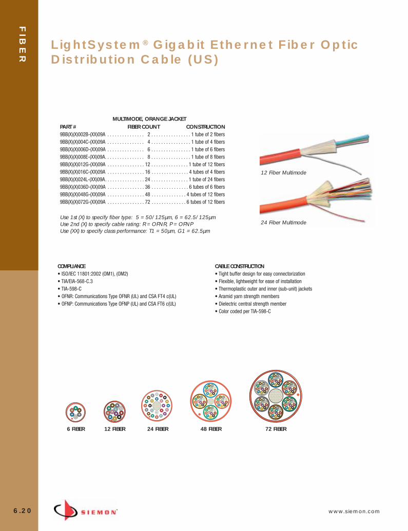
FIB
ER
6.20 www.siemon.com
LightSystem® Gigabit Ethernet Fiber OpticDistribution Cable (US)
MULTIMODE, ORANGE JACKETPART # FIBER COUNT CONSTRUCTION9BB(X)(X)002B-(XX)09A . . . . . . . . . . . . . . . 2 . . . . . . . . . . . . . . . . 1 tube of 2 fibers9BB(X)(X)004C-(XX)09A . . . . . . . . . . . . . . . 4 . . . . . . . . . . . . . . . . 1 tube of 4 fibers9BB(X)(X)006D-(XX)09A . . . . . . . . . . . . . . . 6 . . . . . . . . . . . . . . . . 1 tube of 6 fibers9BB(X)(X)008E-(XX)09A. . . . . . . . . . . . . . . . 8 . . . . . . . . . . . . . . . . 1 tube of 8 fibers9BB(X)(X)012G-(XX)09A . . . . . . . . . . . . . . . 12 . . . . . . . . . . . . . . . 1 tube of 12 fibers9BB(X)(X)016C-(XX)09A . . . . . . . . . . . . . . . 16 . . . . . . . . . . . . . . . 4 tubes of 4 fibers9BB(X)(X)024L-(XX)09A. . . . . . . . . . . . . . . . 24 . . . . . . . . . . . . . . . 1 tube of 24 fibers9BB(X)(X)036D-(XX)09A . . . . . . . . . . . . . . . 36 . . . . . . . . . . . . . . . 6 tubes of 6 fibers9BB(X)(X)048G-(XX)09A . . . . . . . . . . . . . . . 48 . . . . . . . . . . . . . . 4 tubes of 12 fibers9BB(X)(X)072G-(XX)09A . . . . . . . . . . . . . . . 72 . . . . . . . . . . . . . . 6 tubes of 12 fibers
Use 1st (X) to specify fiber type: 5 = 50/125µm, 6 = 62.5/125µmUse 2nd (X) to specify cable rating: R = OFNR, P = OFNPUse (XX) to specify class performance: T1 = 50µm, G1 = 62.5µm
6 FIBER 12 FIBER 24 FIBER 48 FIBER 72 FIBER
12 Fiber Multimode
24 Fiber Multimode
COMPLIANCE• ISO/IEC 11801:2002 (OM1), (OM2)• TIA/EIA-568-C.3 • TIA-598-C • OFNR: Communications Type OFNR (UL) and CSA FT4 c(UL)• OFNP: Communications Type OFNP (UL) and CSA FT6 c(UL)
CABLE CONSTRUCTION • Tight buffer design for easy connectorization• Flexible, lightweight for ease of installation• Thermoplastic outer and inner (sub-unit) jackets• Aramid yarn strength members• Dielectric central strength member• Color coded per TIA-598-C
06_Fiber_Cble_Asmbly_RevB.qxd:ZMax_Catalog 2/12/10 3:30 PM Page 21

www.siemon.com
FIB
ER
6.21
*The protocol pertinent to the transmission distance as noted is Gigabit Ethernet per IEEE 802.3:2005.
LightSystem® Gigabit Ethernet Fiber OpticDistribution Cable (US)
OPTICAL SPECIFICATIONS
Mode and Core Size Cladding Size Coating Size Buffer SizeFiber Type (Microns) (Microns) (Microns) (Microns)
50/125µm 50 ± 3 125 ± 2 245 ± 10 900 ± 5062.5/125µm 62.5 ± 3 125 ± 2 245 ± 10 900 ± 50
MFD = Mode Field Diameter. 8.8 to 9.3 ± 0.5µm @ 1310nm
Typical Maximum Minimum Modal Guaranteed GigabitFiber Wavelength Attenuation Attenuation Bandwidth Transmission Distance*Type nm (dB/km) (dB/km) (MHz • km) (Meters)
50/125µm850 2.6 3.5 500 550
1300 0.6 1.0 500 550
62.5/125µm850 2.9 3.5 200 2751300 0.9 1.0 500 550
Minimum Performance Parameters for LightSystem 50/125µm & 62.5/125µm Multimode Fiber
PHYSICAL SPECIFICATIONS
Nominal Maximum Pulling Tension Maximum Fiber Cable Diameter Newtons (lbs) Net WeightCount mm (in.) Installation Long Term kg/km (lbs/1000 ft.)
OFNR/OFNP OFNR OFNP OFNR OFNP OFNR OFNP
2 4.8 (0.19) 400 (90) 400 (90) 120 (27) 120 (27) 17 (12) 20 (13.1)4 4.8 (0.19) 660 (148) 440 (99) 198 (45) 132 (30) 19 (13) 22 (15)6 4.8 (0.19) 660 (148) 440 (99) 198 (45) 132 (30) 22 (15) 25 (16.5)8 5.8 (0.23) 900 (202) 560 (126) 270 (61) 168 (38) 28 (19) 31 (21)
12 5.8 (0.23) 900 (202) 560 (126) 270 (61) 168 (38) 32 (22) 36 (24.4)16 13.7 (0.54) 1320 (297) 660 (148) 396 (89) 198 (45) 139 (93) 209 (140)24 8.8 (0.35) 1282 (288) 1282 (288) 641 (144) 641 (144) 78 (52.4) 78 (52.4)36 16.5 (0.65) 1320 (297) 660 (148) 396 (89) 198 (45) 213 (143) 221 (148)48 16.0 (0.63) 2700 (607) 1000 (225) 810 (182) 300 (67) 200 (134) 207 (139)72 19.6 (0.77) 2700 (607) 1000 (225) 810 (182) 300 (67) 310 (208) 322 (216)
Minimum Crush Minimum Flex Operating Storage Minimum Bend RadiusFiber Resistance Resistance Temperature TemperatureCount (N/mm) Cycles (°C) (°C) Installation Long Term
OFNR/OFNP OFNR/OFNP OFNR OFNP OFNR/OFNP OFNR/OFNP OFNR/OFNP
2-24 22 25/100 -20/70 -20/50 -40/70 15 x DIA. 10 x DIA.36-72 22 25/100 -20/70 -20/50 -40/70 20 x DIA. 10 x DIA.
06_Fiber_Cble_Asmbly_RevB.qxd:ZMax_Catalog 2/12/10 3:30 PM Page 22
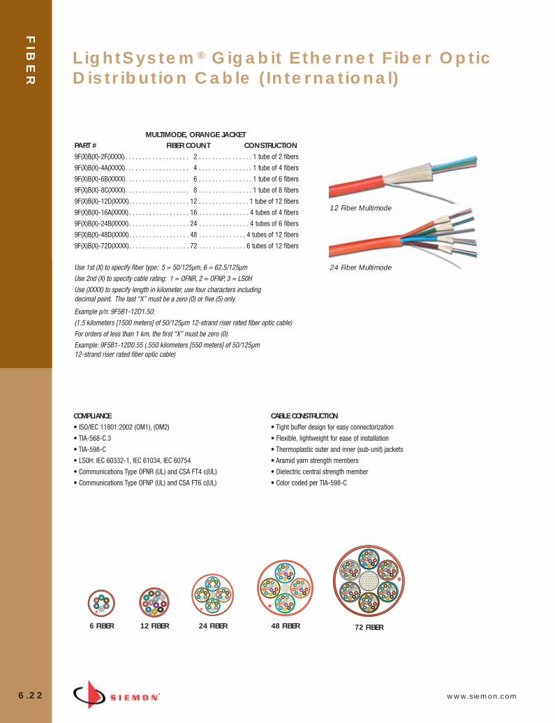
FIB
ER
6.22 www.siemon.com
LightSystem® Gigabit Ethernet Fiber OpticDistribution Cable (International)
MULTIMODE, ORANGE JACKETPART # FIBER COUNT CONSTRUCTION9F(X)B(X)-2F(XXXX) . . . . . . . . . . . . . . . . . . . 2 . . . . . . . . . . . . . . . . 1 tube of 2 fibers
9F(X)B(X)-4A(XXXX). . . . . . . . . . . . . . . . . . . 4 . . . . . . . . . . . . . . . . 1 tube of 4 fibers
9F(X)B(X)-6B(XXXX). . . . . . . . . . . . . . . . . . . 6 . . . . . . . . . . . . . . . . 1 tube of 6 fibers
9F(X)B(X)-8C(XXXX). . . . . . . . . . . . . . . . . . . 8 . . . . . . . . . . . . . . . . 1 tube of 8 fibers
9F(X)B(X)-12D(XXXX). . . . . . . . . . . . . . . . . . 12 . . . . . . . . . . . . . . . 1 tube of 12 fibers
9F(X)B(X)-16A(XXXX) . . . . . . . . . . . . . . . . . . 16 . . . . . . . . . . . . . . . 4 tubes of 4 fibers
9F(X)B(X)-24B(XXXX) . . . . . . . . . . . . . . . . . . 24 . . . . . . . . . . . . . . . 4 tubes of 6 fibers
9F(X)B(X)-48D(XXXX). . . . . . . . . . . . . . . . . . 48 . . . . . . . . . . . . . . 4 tubes of 12 fibers
9F(X)B(X)-72D(XXXX). . . . . . . . . . . . . . . . . . 72 . . . . . . . . . . . . . . 6 tubes of 12 fibers
Use 1st (X) to specify fiber type: 5 = 50/125µm, 6 = 62.5/125µm
Use 2nd (X) to specify cable rating: 1 = OFNR, 2 = OFNP, 3 = LS0H
Use (XXXX) to specify length in kilometer, use four characters including decimal point. The last “X” must be a zero (0) or five (5) only.
Example p/n: 9F5B1-12D1.50:
(1.5 kilometers [1500 meters] of 50/125µm 12-strand riser rated fiber optic cable)
For orders of less than 1 km, the first “X” must be zero (0).
Example: 9F5B1-12D0.55 (.550 kilometers [550 meters] of 50/125µm 12-strand riser rated fiber optic cable)
6 FIBER 12 FIBER 24 FIBER 48 FIBER 72 FIBER
12 Fiber Multimode
24 Fiber Multimode
COMPLIANCE
• ISO/IEC 11801:2002 (OM1), (OM2)
• TIA-568-C.3
• TIA-598-C
• LS0H: IEC 60332-1, IEC 61034, IEC 60754
• Communications Type OFNR (UL) and CSA FT4 c(UL)
• Communications Type OFNP (UL) and CSA FT6 c(UL)
CABLE CONSTRUCTION
• Tight buffer design for easy connectorization
• Flexible, lightweight for ease of installation
• Thermoplastic outer and inner (sub-unit) jackets
• Aramid yarn strength members
• Dielectric central strength member
• Color coded per TIA-598-C
06_Fiber_Cble_Asmbly_RevB.qxd:ZMax_Catalog 2/12/10 3:30 PM Page 23
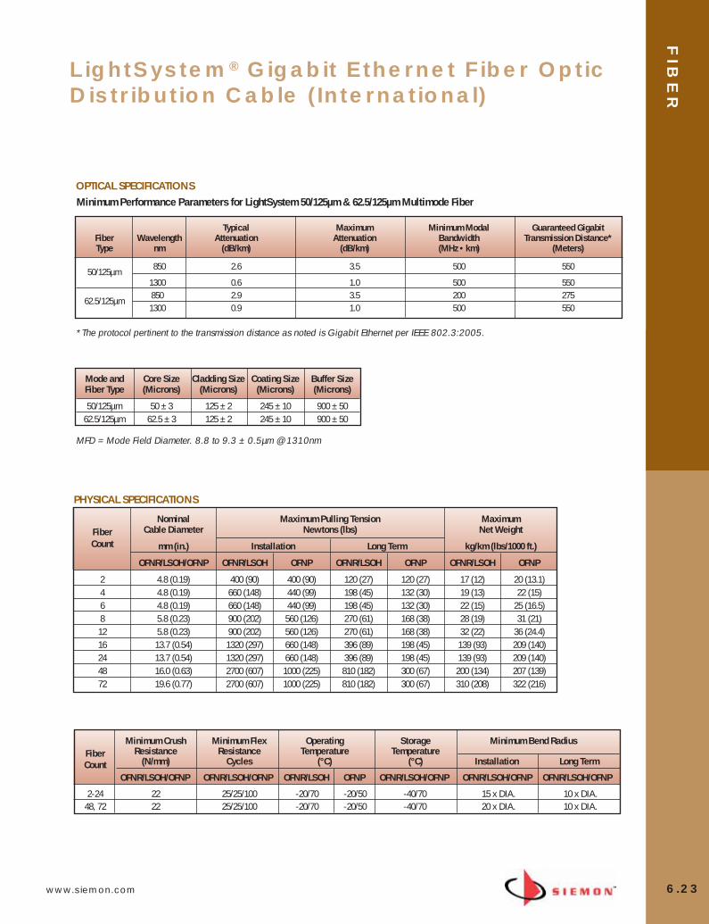
www.siemon.com
FIB
ER
6.23
LightSystem® Gigabit Ethernet Fiber OpticDistribution Cable (International)
OPTICAL SPECIFICATIONS
PHYSICAL SPECIFICATIONS
Nominal Maximum Pulling Tension Maximum Fiber Cable Diameter Newtons (lbs) Net WeightCount mm (in.) Installation Long Term kg/km (lbs/1000 ft.)
OFNR/LSOH/OFNP OFNR/LSOH OFNP OFNR/LSOH OFNP OFNR/LSOH OFNP
2 4.8 (0.19) 400 (90) 400 (90) 120 (27) 120 (27) 17 (12) 20 (13.1)4 4.8 (0.19) 660 (148) 440 (99) 198 (45) 132 (30) 19 (13) 22 (15)6 4.8 (0.19) 660 (148) 440 (99) 198 (45) 132 (30) 22 (15) 25 (16.5)8 5.8 (0.23) 900 (202) 560 (126) 270 (61) 168 (38) 28 (19) 31 (21)
12 5.8 (0.23) 900 (202) 560 (126) 270 (61) 168 (38) 32 (22) 36 (24.4)16 13.7 (0.54) 1320 (297) 660 (148) 396 (89) 198 (45) 139 (93) 209 (140)24 13.7 (0.54) 1320 (297) 660 (148) 396 (89) 198 (45) 139 (93) 209 (140)48 16.0 (0.63) 2700 (607) 1000 (225) 810 (182) 300 (67) 200 (134) 207 (139)72 19.6 (0.77) 2700 (607) 1000 (225) 810 (182) 300 (67) 310 (208) 322 (216)
Minimum Performance Parameters for LightSystem 50/125µm & 62.5/125µm Multimode Fiber
Minimum Crush Minimum Flex Operating Storage Minimum Bend RadiusFiber Resistance Resistance Temperature TemperatureCount (N/mm) Cycles (°C) (°C) Installation Long Term
OFNR/LSOH/OFNP OFNR/LSOH/OFNP OFNR/LSOH OFNP OFNR/LSOH/OFNP OFNR/LSOH/OFNP OFNR/LSOH/OFNP
2-24 22 25/25/100 -20/70 -20/50 -40/70 15 x DIA. 10 x DIA.48, 72 22 25/25/100 -20/70 -20/50 -40/70 20 x DIA. 10 x DIA.
Typical Maximum Minimum Modal Guaranteed GigabitFiber Wavelength Attenuation Attenuation Bandwidth Transmission Distance*Type nm (dB/km) (dB/km) (MHz • km) (Meters)
50/125µm850 2.6 3.5 500 550
1300 0.6 1.0 500 550
62.5/125µm850 2.9 3.5 200 2751300 0.9 1.0 500 550
*The protocol pertinent to the transmission distance as noted is Gigabit Ethernet per IEEE 802.3:2005.
Mode and Core Size Cladding Size Coating Size Buffer SizeFiber Type (Microns) (Microns) (Microns) (Microns)
50/125µm 50 ± 3 125 ± 2 245 ± 10 900 ± 5062.5/125µm 62.5 ± 3 125 ± 2 245 ± 10 900 ± 50
MFD = Mode Field Diameter. 8.8 to 9.3 ± 0.5µm @ 1310nm
06_Fiber_Cble_Asmbly_RevB.qxd:ZMax_Catalog 2/12/10 3:30 PM Page 24

FIB
ER
6.24 www.siemon.com
Aluminum Interlocking Armor Fiber Cable
INDOOR TIGHT BUFFERED DISTRIBUTION ALUMINUM INTERLOCKING ARMOR FIBER CABLE
Part # Fiber Count Construction 9BC(X)(X)006D-(XX)09A 6 1 tube of 6 fibers9BC(X)(X)012G-(XX)09A 12 1 tube of 12 fibers9BC(X)(X)024L-(XX)09A 24 1 tube of 24 fibers9BC(X)(X)036G-(XX)09A 36 3 tubes of 12 fibers9BC(X)(X)048G-(XX)09A 48 4 tubes of 12 fibers9BC(X)(X)072G-(XX)09A 72 6 tubes of 12 fibers9BC(X)(X)096G-(XX)09A 96 8 tubes of 12 fibers9BC(X)(X)144G-(XX)09A 144 12 tubes of 12 fibers
LightSystem Multimode (Orange Jacket)
Part # Fiber Count Construction 9BC(X)(X)006D-(XXXX)A 6 1 tube of 6 fibers9BC(X)(X)012G-(XXXX)A 12 1 tube of 12 fibers9BC(X)(X)024L-(XXXX)A 24 1 tube of 24 fibers9BC(X)(X)036G-(XXXX)A 36 3 tubes of 12 fibers9BC(X)(X)048G-(XXXX)A 48 4 tubes of 12 fibers9BC(X)(X)072G-(XXXX)A 72 6 tubes of 12 fibers9BC(X)(X)096G-(XXXX)A 96 8 tubes of 12 fibers9BC(X)(X)144G-(XXXX)A 144 12 tubes of 12 fibers
XGLO Multimode Laser Optimized (Aqua Jacket), Singlemode (Yellow Jacket)
Use 1st (X) to specify fiber type: 5 = 50/125µm, 6 = 62.5/125µmUse 2nd (X) to specify cable rating: R = OFCR, P = OFCPUse (XX) to specify class performance: T1 = 50µm, G1 = 62.5µm
Use 1st (X) to specify fiber type: 5 = 50/125µm Laser Optimized, 8 = SinglemodeUse 2nd (X) to specify cable rating: R = OFCR, P = OFCPUse (XXXX) to specify class performance: T312 = 50µm Laser Optimized, E205 = Singlemode
COMPLIANCE• ISO/IEC 11801:2002 OM1 • ISO/IEC 11801:2002 OM2 • ISO/IEC 11801:2002 OM3 • ISO/IEC 11801:2002 OS1 • Telcordia GR-409-CORE (Singlemode) • ITU-T G.652.C (Singlemode) • TIA-568-C.3 • TIA-598-C • OFCR: Communications Type OFCR
Engineering Testing Laboratories (ETL) or Underwriters Laboratories (UL) Type OFCR(Conductive Optical Fiber Riser Cable) and c(ETL or UL) OFC-FT6 75C.
• OFCP: Communications Type OFCP Engineering Testing Laboratories (ETL) or Underwriters Laboratories (UL) Type OFCP(Conductive Optical Fiber Plenum Cable) and c(ETL or UL) OFC-FT6 75C.
PHYSICAL SPECIFICATIONS
PERFORMANCE
FEATURES• 900 µm tight buffer• Length marking in 2’ increments• Available OFCR and OFCP
BENEFITS• Aluminum interlock offers greater than
10 times the crush resistance of astandard fiber cable
• Provides installation protection frombending and excessive pull tension
• Significant time and labor reductionsversus conduit or innerduct installations
24 Fiber XGLO Multimode Laser Optimized
• LightSystem see page 6.21• XGLO see page 6.17
24 FIBER
Buffered Optical Fiber
Aramid Yarns
Central Strength
Inner Jacket
Aluminum InterlockArmor
Outer Jacket
6 15.8 (0.624) 13.1 (0.517) 1335 (300) 400 (90) 179 (120) 117 (79)
8 15.8 (0.624 ) 13.3 (0.523) 1335 (300) 400 (90) 188 (126) 129 (87)12 18.8 (0.740) 14.8 (0.584) 1780 (400) 534 (120) 248 (166) 176 (119)
24 24.4 (0.961) 20.9 (0.821 ) 2640 (600) 800 (180) 412 (277) 347 (233)
48 24.4 (0.961) 23.4 (0.921) 2640 (600) 800 (180) 448 (301) 408 (274)
72 32.1 (1.265) 24.7 (0.974) 2640 (600) 800 (180)) 643 (432) 537 (361)
96 32.1 (1.265) 31.1 (1.230) 2640 (600) 800 (180) 775 (521) 749 (503)
144 32.1 (1.265) 31.1 (1.230) 4445 (1000) 1335 (300) 802 (539) 756 (508)
Fiber Count
Nominal Cable Diametermm (in)
OFCR OFCP Installation Long Term OFCR
Maximum = Net Weightkg/km (lbs/1000 ft.)
Maximum Pulling TensionNewtons (lbs)
OFCP
6-144 440 N/cm 100 Cycles -40 to +75 °C -20 to +75 °C -40 to +85 °C -20 to +75 °C 15 X DIA. 10 X DIA.
FiberCount
OFCR OFCP
Minimum Crush Resistance(N/mm)
Operating Temperature (°C)
Storage Temperature (°C)Minimum Flex Resistance
Cycles
Minimum Bend Radius
OFCR OFCP Installation Long Term
06_Fiber_Cble_Asmbly_RevB.qxd:ZMax_Catalog 2/12/10 3:30 PM Page 25

www.siemon.com
FIB
ER
6.25
06_Fiber_Cble_Asmbly_RevB.qxd:ZMax_Catalog 2/12/10 3:30 PM Page 26

FIB
ER
EN
CL
OS
UR
ES
AN
D S
PL
ICIN
G
7.0 www.siemon.com
SECTION CONTENTS
Rack Mount Interconnect Center . . . . . . . . . . . . . . . . . . . . . . . . 7.1 – 7.2
Wall Mount Interconnect Center . . . . . . . . . . . . . . . . . . . . . . . . .7.3 – 7.4
Mini Wall Mount Interconnect Center . . . . . . . . . . . . . . . . . . . . . . . . . .7.4
Fiber Connect Panel . . . . . . . . . . . . . . . . . . . . . . . . . . . . . . . . . .7.5 – 7.6
Compression Fittings . . . . . . . . . . . . . . . . . . . . . . . . . . . . . . . . . . . . . .7.6
Splice Trays . . . . . . . . . . . . . . . . . . . . . . . . . . . . . . . . . . . . . . . . . . . . .7.6
Flat Quick-Pack™ Adapter Plates . . . . . . . . . . . . . . . . . . . . . . . . . . . . .7.7
Siemon’s fiber enclosures provide feature-rich andeasily implemented options for managing criticalfiber connectivity. With versions supporting up to288 fiber ports, Siemon’s Rack Mount InterconnectCenters (RIC 3) offer superior density, accessibility,slack management, security and port identification.
Wall mount versions, which share many of theRIC3’s user-friendly features, are also available.
07_Fiber_Enclosure.qxd:ZMax_Catalog 1/4/10 11:41 AM Page 1

www.siemon.com
FIB
ER
EN
CL
OS
UR
ES
AN
D S
PL
ICIN
G
7.1
Rack Mount InterconnectCenter (RIC3)
The RIC3 provides the best overall value for exceptional fiber management.The RIC3 enclosure offers superior fiber density (up to 288 fibers in just 4U)without sacrificing fiber protection and accessibility. Features include a fullyremovable tray, improved labeling, standard front and rear door locks, andsingle-finger door latches. With superior cable management, portidentification, fiber accessibility and security, the RIC3 is the best way toprotect mission critical fiber connections.
Latching and LockingThe RIC3 features a single-finger latch onboth front and rear doors. Front and reardoors include a lock for added security
Quick-Pack™ AdapterPlatesSiemon Quick-Pack adapter plates can beinserted or removed with a single-fingerlatch for quick and easy access to fiberconnections.
Removable TrayThe RIC3 cable management tray is fixed inplace, but can be removed from the frontor rear of the enclosure and moved to awork table for more convenient loading.
Quick-Release Hinges — Spring loaded quick-release hingesenable easy removal of front and rear doors for complete access tofiber connections
Enhanced Labeling — Label virtually any port configuration withour hinged labels. The labels hang on the front door for improvedvisibility. When the door is opened, labels flip down allowing readyviewing of the label and corresponding ports
Rotating Grommets — Patented rotating grommets facilitateloading and retention of jumpers and fiber while minimizingmicrobending stress when using the sliding tray
Complete Access — Management tray has a positive stop in bothfront and rear working positions providing complete access formoving, adding, changing, or cleaning of fiber connections
Maximum Capacity — The RIC3 enables a maximum amount offibers to be patched or patched and spliced in a 2, 3, and 4Uenclosure without compromising accessibility. This allows moreefficient utilization of rack space
Superior Design — Top and bottom access holes located at therear of the enclosure allow fibers to be routed between tandemenclosures without having to run fibers outside of the enclosure
1
2
3
4
5
6
1
2
3
4
5
6
07_Fiber_Enclosure.qxd:ZMax_Catalog 1/4/10 11:41 AM Page 2

FIB
ER
EN
CL
OS
UR
ES
AN
D S
PL
ICIN
G
7.2 www.siemon.com
Siemon RIC3 enclosures are designed for enhanced fiber management and ease of use. They are compatible with anarray of Siemon fiber Quick-Pack™ adapter plates for your choice of fiber adapters and port density (see page 7.7).
RIC3-48-01 . . . . . . . . . . . . . . . . 48- to 192-port Rack Mount InterconnectCenter, accepts (8) Quick-Pack adapter plates,3U , black
height: 133mm (5.25 in.), width: 432mm (17.00 in.), depth: 380mm (14.95 in.)
RIC3-72-01 . . . . . . . . . . . . . . . . 72- to 288-port Rack Mount InterconnectCenter, accepts (12) Quick-Pack adapterplates, 4U, black
height: 178mm (7.00 in.), width: 432mm (17.00 in.), depth: 380mm (14.95 in.)
Part # DescriptionRIC3-24-01 . . . . . . . . . . . . . . . . 24- to 96-port Rack Mount Interconnect
Center, accepts (4) Quick-Pack adapter plates,2U, black
height: 86.6mm (3.41 in.), width: 432mm (17.00 in.), depth: 380mm (14.95 in.)
Part # DescriptionRIC3-36-01 . . . . . . . . . . . . . . . . 36- to 144-port Rack Mount Interconnect
Center, accepts (6) Quick-Pack adapter plates,2U, black
height: 86.6mm (3.41 in.), width: 432mm (17.00 in.), depth: 380mm (14.95 in.)
Note: 1U = 44.5mm (1.75 in.)
Note: All RIC products include laser-printable labels*, cable ties, rack-mounting hardware, and pre-installed fiber management clips.
*Visit www.siemon.com for labeling software.
MAXIMUM SPLICING CAPACITY
SPLICE TYPE RIC24 RIC36 RIC48 RIC72Fusion 96 96 96 144
MAXIMUM RIC3 FIBER CAPACITY
# FIBERS PER QUICK-PACK ADAPTER OPTIONS RIC24 RIC36 RIC48 RIC726 ST, SC 24 36 48 728 ST, SC 32 48 64 96
12 ST, SC 48 72 96 14416 LC 64 96 128 19224 LC 96 144 192 288
RACK MOUNT INTERCONNECT CENTER (RIC3)
07_Fiber_Enclosure.qxd:ZMax_Catalog 1/4/10 11:41 AM Page 3
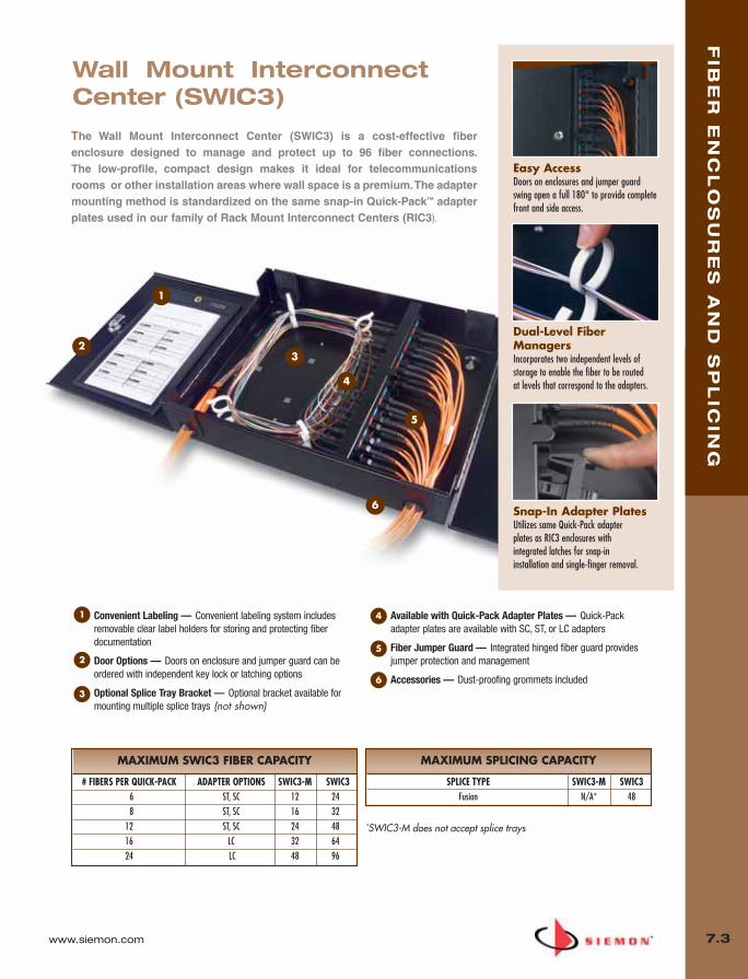
www.siemon.com
FIB
ER
EN
CL
OS
UR
ES
AN
D S
PL
ICIN
G
7.3
Convenient Labeling — Convenient labeling system includesremovable clear label holders for storing and protecting fiberdocumentation
Door Options — Doors on enclosure and jumper guard can beordered with independent key lock or latching options
Optional Splice Tray Bracket — Optional bracket available formounting multiple splice trays (not shown)
Available with Quick-Pack Adapter Plates — Quick-Packadapter plates are available with SC, ST, or LC adapters
Fiber Jumper Guard — Integrated hinged fiber guard providesjumper protection and management
Accessories — Dust-proofing grommets included
1 4
5
6
2
3
1
23
4
5
6
Wall Mount InterconnectCenter (SWIC3)
The Wall Mount Interconnect Center (SWIC3) is a cost-effective fiberenclosure designed to manage and protect up to 96 fiber connections. The low-profile, compact design makes it ideal for telecommunicationsrooms or other installation areas where wall space is a premium. The adaptermounting method is standardized on the same snap-in Quick-Pack™ adapterplates used in our family of Rack Mount Interconnect Centers (RIC3).
Dual-Level FiberManagersIncorporates two independent levels of storage to enable the fiber to be routed at levels that correspond to the adapters.
Snap-In Adapter PlatesUtilizes same Quick-Pack adapter plates as RIC3 enclosures with integrated latches for snap-in installation and single-finger removal.
Easy AccessDoors on enclosures and jumper guard swing open a full 180° to provide completefront and side access.
*SWIC3-M does not accept splice trays
MAXIMUM SPLICING CAPACITY
SPLICE TYPE SWIC3-M SWIC3Fusion N/A* 48
MAXIMUM SWIC3 FIBER CAPACITY
# FIBERS PER QUICK-PACK ADAPTER OPTIONS SWIC3-M SWIC36 ST, SC 12 248 ST, SC 16 32
12 ST, SC 24 4816 LC 32 6424 LC 48 96
07_Fiber_Enclosure.qxd:ZMax_Catalog 1/4/10 11:41 AM Page 4
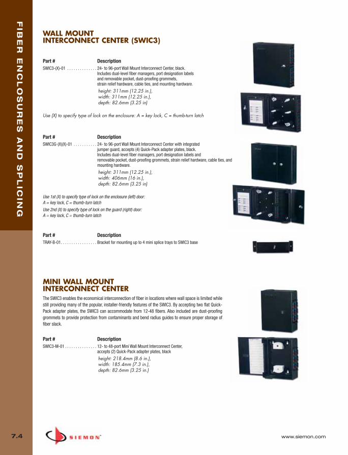
FIB
ER
EN
CL
OS
UR
ES
AN
D S
PL
ICIN
G
7.4 www.siemon.com
MINI WALL MOUNT INTERCONNECT CENTERThe SWIC3 enables the economical interconnection of fiber in locations where wall space is limited whilestill providing many of the popular, installer-friendly features of the SWIC3. By accepting two flat Quick-Pack adapter plates, the SWIC3 can accommodate from 12-48 fibers. Also included are dust-proofinggrommets to provide protection from contaminants and bend radius guides to ensure proper storage offiber slack.
Part # DescriptionSWIC3-M-01 . . . . . . . . . . . . . . . 12- to 48-port Mini Wall Mount Interconnect Center,
accepts (2) Quick-Pack adapter plates, black
height: 218.4mm (8.6 in.),width: 185.4mm (7.3 in.),depth: 82.6mm (3.25 in.)
WALL MOUNT INTERCONNECT CENTER (SWIC3)
Part # DescriptionSWIC3-(X)-01 . . . . . . . . . . . . . . 24- to 96-port Wall Mount Interconnect Center, black.
Includes dual-level fiber managers, port designation labels and removable pocket, dust-proofing grommets, strain relief hardware, cable ties, and mounting hardware.
height: 311mm (12.25 in.), width: 311mm (12.25 in.), depth: 82.6mm (3.25 in)
Use (X) to specify type of lock on the enclosure: A = key lock, C = thumb-turn latch
Part # DescriptionSWIC3G-(X)(X)-01 . . . . . . . . . . . 24- to 96-port Wall Mount Interconnect Center with integrated
jumper guard, accepts (4) Quick-Pack adapter plates, black. Includes dual-level fiber managers, port designation labels and removable pocket, dust-proofing grommets, strain relief hardware, cable ties, andmounting hardware.
height: 311mm (12.25 in.), width: 406mm (16 in.), depth: 82.6mm (3.25 in)
Use 1st (X) to specify type of lock on the enclosure (left) door: A = key lock, C = thumb-turn latch
Use 2nd (X) to specify type of lock on the guard (right) door:A = key lock, C = thumb-turn latch
Part # DescriptionTRAY-B-01. . . . . . . . . . . . . . . . . Bracket for mounting up to 4 mini splice trays to SWIC3 base
07_Fiber_Enclosure.qxd:ZMax_Catalog 1/4/10 11:41 AM Page 5

www.siemon.com
FIB
ER
EN
CL
OS
UR
ES
AN
D S
PL
ICIN
G
7.5
Lanced Tabs — Provide convenient cable anchor points forincoming jacketed fiber cable
Front Fiber Clips — Manage up to 36 duplex fiber jumpers (72fibers total)
Label Holder — Protects fiber jumpers and is readily removablevia release of factory-installed snap-latches
Up to 3 Optional Splice Trays — Can be mounted to manage andprotect either mechanical or fusion splices
Rear Fiber Clips — Manage cable slack while maintainingminimum bend radius requirements
41
2
3
5
1
2
3
4
5
Siemon’s popular Fiber Connect Panels (FCP3-DWR and FCP3-RACK)economically connect, protect, and manage up to 72 fibers/1U. Itaccepts Siemon’s Quick-Pack™ adapter plates with patented single-finger access. The FCP3-DWR makes access to the connections easyvia a fixed tray that can be released and slid out of the front or rear ofthe enclosure. High Density
FCP3 enclosures accommodate up to 72fibers in only 1U on a 19 inch rack.
Sliding TrayThe FCP3-DWR (drawer version) features atray that slides out from the front or rear,providing easy access to fiber connections.The entire tray can be removed and placedon a work table for more convenienttermination.
MAXIMUM SPLICING CAPACITY
SPLICE TYPE FCP3Fusion 72
MAXIMUM FCP3 FIBER CAPACITY
# FIBERS PER QUICK-PACK ADAPTER OPTIONS FCP36 ST, SC 188 ST, SC 24
12 ST, SC, LC 3616 LC 4824 LC 72
Fiber Connect Panel (FCP3)
07_Fiber_Enclosure.qxd:ZMax_Catalog 1/4/10 11:41 AM Page 6

TRAY-3 TRAY-M-3
Part # DescriptionTRAY-3. . . . . . . . . . . . . . Standard splice tray for up to 24 fusion splices
with sleeve protection. For use with RIC3 andFCP3 fiber enclosures
TRAY-M-3 . . . . . . . . . . . Mini splice tray for up to 12 fusion spliceswith sleeve protection. For use with SWIC3enclosures
Mini Tray Dimensionsheight: 103mm (4.07 in.), width: 179mm (7.06 in.), depth: 8.13mm (0.32 in.)
Standard Tray Dimensionsheight: 103mm (4.07 in.), width: 298mm (11.75 in.), depth: 8.13mm (0.32 in.)
FIB
ER
EN
CL
OS
UR
ES
AN
D S
PL
ICIN
G
7.6 www.siemon.com
COMPRESSION FITTINGSCompression fittings are utilized as an enhanced method for securing cables to FCP3 fiberenclosures. Acme threads on the body prevent skipping, allowing for faster installations of lock-nuts.
Part # DescriptionCF-(XX) . . . . . . . . . . . . . . . . . . . Compression fitting
Use (XX) to specify fiber diameter: 40 = 5.8 – 13.9mm (0.23 – 0.55 in.), 51 = 11.4 – 18.0mm (0.45 – 0.71 in.), 60 = 15.0 – 25.4mm (0.59 – 1.00 in.)
FCP3-RACK
FCP3-DWR
Part # DescriptionFCP3-DWR . . . . . . . . . . . . . . . . 6- to 72-port Fiber Connect Panel with sliding tray, accepts (3)
Quick-Pack™ adapter plates, 1U, black. Includes mounting brackets, housing/tray, fiber managers, grommets, label holders, and labelsheight: 43.2mm (1.7 in.) width: 482.6mm (19.0 in.) depth: 355.6mm (14.0 in.)
FCP3-RACK . . . . . . . . . . . . . . . . 6- to 72-port Fiber Connect Panel with fixed tray, accepts (3) Quick-Pack adapter plates, 1U, black. Includes mounting brackets, housing/cover, fiber managers and grommetheight: 43.2mm (1.7 in.) width: 482.6mm (19.0 in.)depth: 241.3mm (9.5 in.)
Note: 1U =44.5 mm (1.75 in.)
FIBER CONNECT PANEL (FCP3)
These aluminum trays come with a clear, snap-on polycarbonate cover and can bestacked for high-density applications. The standard tray holds up to 24 splices. The mini-tray for use with the SWIC3, accommodates up to 12 splices.
SPLICE TRAYS (XGLO® AND LIGHTSYSTEM®)
07_Fiber_Enclosure.qxd:ZMax_Catalog 1/4/10 11:41 AM Page 7
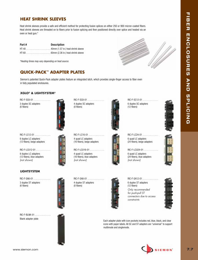
Heat shrink sleeves provide a safe and efficient method for protecting fusion splices on either 250 or 900 micron coated fibers.Heat shrink sleeves are threaded on to fibers prior to fusion splicing and then positioned directly over splice and heated via anoven or heat gun.*
Part # DescriptionHT-40 . . . . . . . . . . . . . . . . . . . . 40mm (1.57 in.) heat shrink sleeve
HT-60 . . . . . . . . . . . . . . . . . . . . 60mm (2.36 in.) heat shrink sleeve
www.siemon.com
FIB
ER
EN
CL
OS
UR
ES
AN
D S
PL
ICIN
G
7.7
Siemon’s patented Quick-Pack adapter plates feature an integrated latch, which provides single-finger access to fiber evenin fully populated enclosures.
RIC-F-SC6-01 . . . . . . . . . . . . . .
3 duplex SC adapters (6 fibers)
RIC-F-SC8-01 . . . . . . . . . . . . . .
4 duplex SC adapters (8 fibers)
RIC-F-SC12-01 . . . . . . . . . . . . .
6 duplex SC adapters (12 fibers)
RIC-F-SA6-01 . . . . . . . . . . . . . .
3 duplex ST adapters (6 fibers)
RIC-F-SA8-01 . . . . . . . . . . . . . .
4 duplex ST adapters (8 fibers)
RIC-F-SA12-01 . . . . . . . . . . . . .
6 duplex ST adapters (12 fibers)
Only recommended for push-pull STconnectors due to accessconstraints
RIC-F-LC12-01 . . . . . . . . . . . . .
6 duplex LC adapters (12 fibers), beige adapters
RIC-F-LCU12-01 . . . . . . . . . . . .
6 duplex LC adapters (12 fibers), blue adapters(not shown)
RIC-F-LC16-01 . . . . . . . . . . . . .
4 quad LC adapters (16 fibers), beige adapters
RIC-F-LCU16-01 . . . . . . . . . . . .
4 quad LC adapters (16 fibers), blue adapters(not shown)
RIC-F-LC24-01 . . . . . . . . . . . . .
6 quad LC adapters (24 fibers), beige adapters
RIC-F-LCU24-01 . . . . . . . . . . . .
6 quad LC adapters (24 fibers), blue adapters(not shown)
Each adapter plate with icon pockets includes red, blue, black, and clearicons with paper labels. All SC and ST adapters are “universal” to supportmultimode and singlemode.
RIC-F-BLNK-01 . . . . . . . . . . . . .
Blank adapter plate
XGLO® & LIGHTSYSTEM®
LIGHTSYSTEM
QUICK-PACK™ ADAPTER PLATES
HEAT SHRINK SLEEVES
*Heating times may vary depending on heat source.
07_Fiber_Enclosure.qxd:ZMax_Catalog 1/4/10 11:41 AM Page 8

www.siemon.com
Ma
pIT
®G
2 IN
FR
AS
TR
UC
TU
RE
MA
NA
GE
ME
NT
8.0
SECTION CONTENTS
MapIT G2 Control Panels . . . . . . . . . . . . . . . . . . . . . . . . . . . . . . 8.1 – 8.2
Optional Accessories . . . . . . . . . . . . . . . . . . . . . . . . . . . . . . . . . . . . . .8.2
MapIT G2 Copper Systems . . . . . . . . . . . . . . . . . . . . . . . . . . . . . 8.3 – 8.4
MapIT G2 Fiber Systems . . . . . . . . . . . . . . . . . . . . . . . . . . . . . . 8.5 – 8.6
Introducing MapIT G2, a complete upgrade of Siemon’s popular MapIT intelligent infrastructure management (IIM)solution. MapIT G2 integrates a powerfulcombination of innovative Smart PatchPanels, user-friendly Master Control Panelsand MapIT IM software to provide real-timetracking and reporting of network-widephysical layer activity. This benchmark IIMsystem offers truly unparalleled ability tomanage a complex network.
• 28% of downtime in data centers is dueto change and human error
• Every hour of downtime costs $100K
• 49% of Fortune 1000 IT managers listedreducing cost as a top priority
08_MapIT_G2.qxd:ZMax_Catalog 1/4/10 11:44 AM Page 1

www.siemon.com
Ma
pIT
®G
2
8.1
Superior Density Low profile 1U design increases density and reduces usage of costlyrack and cabinet space in data centers and telecommunicationrooms
ScalableMCP can monitor as few as 48 ports and up to 65,000 ports to cost effectively monitor small remote offices, large data centers oroffice/campus environments
Reduced Power Consumption 75% lower power consumption compared to traditional intelligentpatching systems for monitoring equipment. This power savings de-creases operating expenses and provides a more environmentallyfriendly solution
Excellent Thermal Efficiency The MCP and DCP’s combination of ultra low heat generation and alow profile design limits airflow impedance, helping to maximizecooling efficiency in data center environments
Simple, Multi-Functional User InterfaceLarge graphic LCD and keypad enables technicians to view circuittraces, patch cord traces, perform diagnostics and more, improv-ing efficiency in maintenance and MAC work
Ease of Implementation Simple design and straightforward implementation and setup re-duces the time and technician skill required to design and install thesystem
High Resiliency Redundant power and Ethernet connectivity provides increased relia-bility, reduces downtime
Redundant power and EthernetMCP Graphic LCD Field-terminated control connections(RJ-45 Front or S310 Rear)
The MapIT G2 Master Control Panel (MCP) collects all network infrastructure data provided by theSmart Patch Panels and Fiber Enclosures, monitoring up to 2880 ports in just 1 rack space (1U). The MCP and DCP features an integrated LCD display and keypad, which provide technicians access to critical network architecture and diagnostic information. By providing this interface locallywithin the patching zone, the MapIT G2 virtually eliminates the need for technicians to carry PDAs ordirectly access the MapIT software server. This interface allows full end-to-end graphic circuit tracesfor any channel in the system and can perform extensive diagnostic tasks on any component or port.
MapIT G2 Master and Distribution Control Panels
08_MapIT_G2.qxd:ZMax_Catalog 1/4/10 11:44 AM Page 2
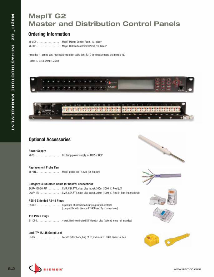
Ma
pIT
®G
2 IN
FR
AS
TR
UC
TU
RE
MA
NA
GE
ME
NT
8.2 www.siemon.com
MapIT G2 Master and Distribution Control Panels
M-MCP . . . . . . . . . . . . . . . . . . . MapIT Master Control Panel, 1U, black*
M-DCP. . . . . . . . . . . . . . . . . . . . MapIT Distribution Control Panel, 1U, black*
*Includes (1) probe pen, rear cable manager, cable ties, S310 termination caps and ground lug
Optional Accessories
Power SupplyM-PS. . . . . . . . . . . . . . . . . . . . . 6v, 3amp power supply for MCP or DCP
Replacement Probe PenM-PEN. . . . . . . . . . . . . . . . . . . . MapIT probe pen, 7.62m (25 ft.) cord
Category 5e Shielded Cable for Control Connections9A5R4-E1-06-RIA . . . . . . . . . . . CMR, CSA FT4, riser, blue jacket, 305m (1000 ft.) Reel (US)
9A5R4-E2 . . . . . . . . . . . . . . . . . CMR, CSA FT4, riser, blue jacket, 305m (1000 ft.) Reel-in-Box (International)
PS8-8 Shielded RJ-45 PlugsPS-8-8 . . . . . . . . . . . . . . . . . . . 8-position shielded modular plug with 8 contacts
(compatible with Siemon PT-908 and Tyco crimp tools)
110 Patch PlugsS110P4 . . . . . . . . . . . . . . . . . . . 4-pair, field-terminated S110 patch plug (colored icons not included)
LockIT™ RJ-45 Outlet LockLL-05 . . . . . . . . . . . . . . . . . . . . LockIT Outlet Lock, bag of 10, includes 1 LockIT Universal Key
Ordering Information
Note: 1U = 44.5mm (1.75in.)
08_MapIT_G2.qxd:ZMax_Catalog 1/4/10 11:44 AM Page 3

www.siemon.com
Ma
pIT
®G
2 IN
FR
AS
TR
UC
TU
RE
MA
NA
GE
ME
NT
8.3
MapIT G2 Smart Patch Panels The MapIT G2 Smart Patch Panel (SPP) is an industry first in intelligent infrastructure management. The panel features on-panel intelligence and a combination of LEDs and a backlit graphic LCD to guidetechnicians. The LCD can be used to display patch cord trace and diagnostic information. It can also beused to troubleshoot network issues, which can drastically reduce downtime and increase productivity.Since it is actively connected to your database, you could even use it as a virtual label, dynamically dis-playing panel and port information directly from the MapIT database.
On Panel Intelligence Port monitoring capability is built into each patch panel - Increases density and reduces cost.
High Reliability Redundant power and communications to each smart patch panel.
Self DiagnosticsIf a SPP is disconnected from the system, the MCP will report it to the MapIT software, which can trigger an alert to anIT manager or technician to fix the problem.
ScalableEqually cost effective solution for monitoring small remote offices, large data centers or office/campus environments.
MapIT G2 Copper Systems
Ordering Information
Patch PanelsM-SPP-K24E . . . . . . . . . . . . . . . MapIT 24-port modular Smart Patch Panel, accepts Siemon UTP or shielded
keystone outlets (sold separately)Includes (4) S110 termination caps, 24 cable ties and panel ground lug
24 MapIT IM software port licenses included with each panel
Siemon Keystone OutletsZ6A-SK01 . . . . . . . . . . . . . . . . . Keystone shielded Z-MAX™ 6A outlet, black*, T568A/B
Z6A-K01 . . . . . . . . . . . . . . . . . . Keystone UTP Z-MAX 6A outlet, black*, T568A/B
Z6-K01 . . . . . . . . . . . . . . . . . . . Keystone UTP Z-MAX 6 outlet, black*, T568A/B
MX6-K01. . . . . . . . . . . . . . . . . . Keystone UTP MAX 6 outlet, black*, T568A/B (not shown)
*Other colors available
Keystone Z-MAX Shielded Outlet
Keystone Z-MAX UTP Outlet
MapIT IM Software
This robust program manages, monitors and documents your network infrastructure through Siemon’s MapIT G2 connectivity.For more information on MapIT IM software, including features, capabilities and system requirements, please contact your localSiemon representative, or visit www.siemon.com.
08_MapIT_G2.qxd:ZMax_Catalog 1/4/10 11:44 AM Page 4

Ma
pIT
®G
2 IN
FR
AS
TR
UC
TU
RE
MA
NA
GE
ME
NT
8.4 www.siemon.com
Supports Siemon’s High-Performance Systems Category 6A shielded, category 6A UTP and category 6 UTP
Reliable Integrated Sensor Connections Sensor pins feature 50 microinches gold plating for long-term contactreliability and resistance to corrosion
Simple Testing Features Sensor pin is accessible at the rear of the boot for test and mappingpurposes
Robust Strain Relief Over-molded boots provide plug to cable strain relief and retention ofsensor pin. 100% transmission testing ensures component and chan-nel performance
M-10GMCS-(XX)M(XX)L . . . . . . . MapIT G2 Category 6A shielded, double-ended, stranded modular cord, color-matching boot, T568A/B, LS0H
Jacket Color02 = White04 = Gray06 = Blue
Length01 = 1 m (3.3 ft.)02 = 2 m (6.6 ft.)03 = 3 m (9.8 ft.)05 = 5 m (16.4 ft.)
M-MC6-(XX)-(XX). . . . . . . . . . . . MapIT G2 Category 6 UTP, double-ended, stranded modular cord, color-matching boot, T568A/B, CMG
Jacket Color02 = White04 = Gray06 = BlueLength
03 = 0.91 m (3 ft.)05 = 1.52 m (5 ft.)07 = 2.13 m (7 ft.)10 = 3.05 m (10 ft.)15 = 4.57 m (15 ft.)20 = 6.10 m (20 ft.)
Ordering Information
MapIT G2 Copper Systems
MapIT G2 Patch CordsThese advanced cords also feature a 9th wire and sensorpin contained in a robust over-molded boot. This embed-ded sensor technology enables tracking of connectionsbetween Smart Patch Panel ports.
M-10GMC-(XX)-(XX). . . . . . . . . . MapIT G2 Category 6A UTP, double-ended, stranded modular cord, color-matching boot, T568A/B, CMG
Jacket Color02 = White04 = Gray06 = Blue
Length03 = 0.91 m (3 ft.)05 = 1.52 m (5 ft.)07 = 2.13 m (7 ft.)10 = 3.05 m (10 ft.)15 = 4.57 m (15 ft.)20 = 6.10 m (20 ft.)
08_MapIT_G2.qxd:ZMax_Catalog 1/4/10 11:44 AM Page 5
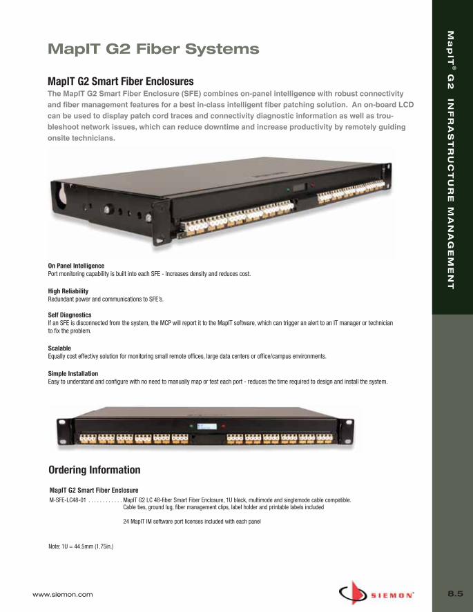
www.siemon.com
Ma
pIT
®G
2 IN
FR
AS
TR
UC
TU
RE
MA
NA
GE
ME
NT
8.5
MapIT G2 Fiber Systems
On Panel IntelligencePort monitoring capability is built into each SFE - Increases density and reduces cost.
High ReliabilityRedundant power and communications to SFE’s.
Self DiagnosticsIf an SFE is disconnected from the system, the MCP will report it to the MapIT software, which can trigger an alert to an IT manager or technicianto fix the problem.
ScalableEqually cost effectivy solution for monitoring small remote offices, large data centers or office/campus environments.
Simple InstallationEasy to understand and configure with no need to manually map or test each port - reduces the time required to design and install the system.
MapIT G2 Smart Fiber EnclosureM-SFE-LC48-01 . . . . . . . . . . . . MapIT G2 LC 48-fiber Smart Fiber Enclosure, 1U black, multimode and singlemode cable compatible.
Cable ties, ground lug, fiber management clips, label holder and printable labels included
24 MapIT IM software port licenses included with each panel
Ordering Information
Note: 1U = 44.5mm (1.75in.)
MapIT G2 Smart Fiber EnclosuresThe MapIT G2 Smart Fiber Enclosure (SFE) combines on-panel intelligence with robust connectivityand fiber management features for a best in-class intelligent fiber patching solution. An on-board LCDcan be used to display patch cord traces and connectivity diagnostic information as well as trou-bleshoot network issues, which can reduce downtime and increase productivity by remotely guidingonsite technicians.
08_MapIT_G2.qxd:ZMax_Catalog 1/4/10 11:44 AM Page 6
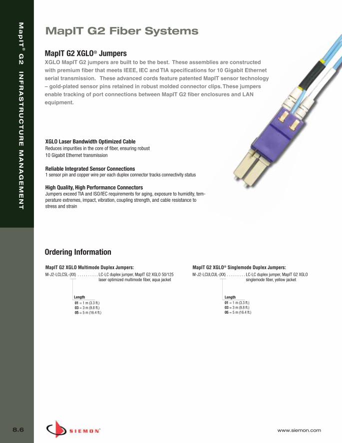
MapIT G2 Fiber Systems
MapIT G2 XGLO® JumpersXGLO MapIT G2 jumpers are built to be the best. These assemblies are constructedwith premium fiber that meets IEEE, IEC and TIA specifications for 10 Gigabit Ethernetserial transmission. These advanced cords feature patented MapIT sensor technology– gold-plated sensor pins retained in robust molded connector clips. These jumpersenable tracking of port connections between MapIT G2 fiber enclosures and LAN equipment.
MapIT G2 XGLO Multimode Duplex Jumpers:M-J2-LCLC5L-(XX) . . . . . . . . . . LC-LC duplex jumper, MapIT G2 XGLO 50/125
laser optimized multimode fiber, aqua jacket
MapIT G2 XGLO® Singlemode Duplex Jumpers:M-J2-LCULCUL-(XX) . . . . . . . . . LC-LC duplex jumper, MapIT G2 XGLO
singlemode fiber, yellow jacket
Ordering Information
Length01 = 1 m (3.3 ft.)03 = 3 m (9.8 ft.)05 = 5 m (16.4 ft.)
Length01 = 1 m (3.3 ft.)03 = 3 m (9.8 ft.)05 = 5 m (16.4 ft.)
Ma
pIT
®G
2 IN
FR
AS
TR
UC
TU
RE
MA
NA
GE
ME
NT
8.6 www.siemon.com
XGLO Laser Bandwidth Optimized Cable Reduces impurities in the core of fiber, ensuring robust 10 Gigabit Ethernet transmission
Reliable Integrated Sensor Connections 1 sensor pin and copper wire per each duplex connector tracks connectivity status
High Quality, High Performance Connectors Jumpers exceed TIA and ISO/IEC requirements for aging, exposure to humidity, tem-perature extremes, impact, vibration, coupling strength, and cable resistance tostress and strain
08_MapIT_G2.qxd:ZMax_Catalog 1/4/10 11:44 AM Page 7

www.siemon.com
Ma
pIT
®G
2 IN
FR
AS
TR
UC
TU
RE
MA
NA
GE
ME
NT
8.7
08_MapIT_G2.qxd:ZMax_Catalog 1/4/10 11:44 AM Page 8

www.siemon.com
FA
CE
PL
AT
ES
AN
D M
OU
NT
ING
AC
CE
SS
OR
IES
9.0
SECTION CONTENTS
LockIT . . . . . . . . . . . . . . . . . . . . . . . . . . . . . . . . . . . . . . . . . . . .9.1 – 9.2
10G™ MAX® Faceplates . . . . . . . . . . . . . . . . . . . . . . . . . . . . . . . . . . . .9.3
MAX Modular Faceplates . . . . . . . . . . . . . . . . . . . . . . . . . . . . . . . . . . .9.4
MAX Stainless Steel Faceplates . . . . . . . . . . . . . . . . . . . . . . . . . . . . . .9.4
10G MAX International Faceplates . . . . . . . . . . . . . . . . . . . . . . . . . . . .9.5
MAX International Faceplates . . . . . . . . . . . . . . . . . . . . . . . . . . . . . . . .9.5
MAX Outlet Blanks and Doors . . . . . . . . . . . . . . . . . . . . . . . . . . . . . . . .9.5
MAX Modular Furniture Adapters . . . . . . . . . . . . . . . . . . . . . . . . . . . . .9.6
MAX Outlet and Faceplate Accessories . . . . . . . . . . . . . . . . . . . . . . . . .9.6
MAX Tamper-Proof Faceplate . . . . . . . . . . . . . . . . . . . . . . . . . . . . . . . .9.7
Surface Mounting Boxes . . . . . . . . . . . . . . . . . . . . . . . . . . . . . . . . . . . .9.7
Stand-off Rings for MAX and CT Faceplates . . . . . . . . . . . . . . . . . . . . .9.7
Z-MAX (MX-SMZ) Surface Mount Boxes . . . . . . . . . . . . . . . . . . . . . . . .9.8
MX-SM Surface Mount Boxes . . . . . . . . . . . . . . . . . . . . . . . . . . .9.8 – 9.9
MX-SM Multimedia Bezels and Components . . . . . . . . . . . . . . . . . . . . 9.9
Multi-User Telecommunications Outlet Assembly (MUTOA) . . . . . . . . .9.10
Fiber Outlet Box (FOB2) . . . . . . . . . . . . . . . . . . . . . . . . . . . . . . . . . . .9.11
Fiber Bezels . . . . . . . . . . . . . . . . . . . . . . . . . . . . . . . . . . . . . . . . . . . .9.11
TERA®-MAX Adapters for CT Faceplates . . . . . . . . . . . . . . . . . . . . . . .9.12
CT Faceplates . . . . . . . . . . . . . . . . . . . . . . . . . . . . . . . . . . . . . . . . . . .9.12
CT Modular Furniture Adapters . . . . . . . . . . . . . . . . . . . . . . . . . . . . . .9.12
Siemon’s comprehensive offering of faceplates
and mounting accessories deliver innovative
and flexible options for support of work area con-
nectivity. Designed to be used with MAX and
Z-MAX modules and TERA outlets, MAX modular
faceplates are available in a range of port counts
and colors to support nearly any configuration.
09_FP_Mounting.qxd:ZMax_Catalog 2/12/10 4:10 PM Page 1
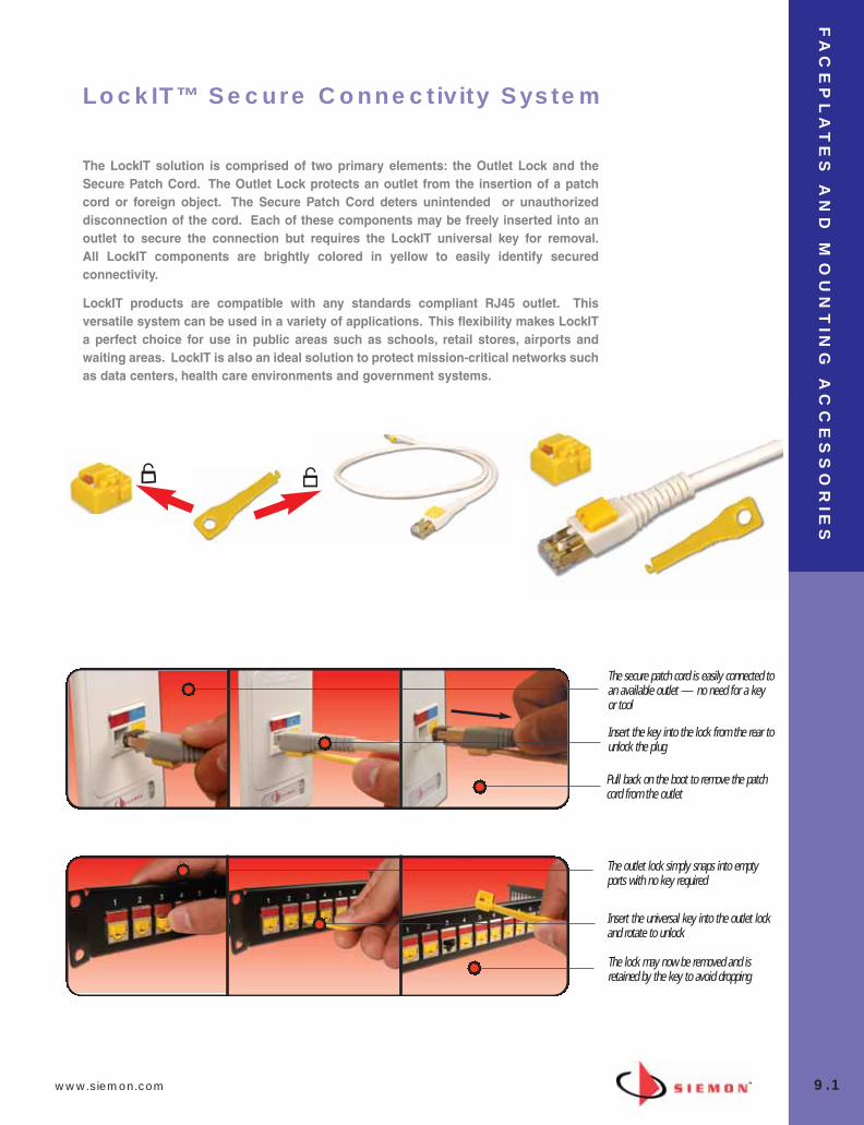
www.siemon.com
FA
CE
PL
AT
ES
AN
D M
OU
NT
ING
AC
CE
SS
OR
IES
9.1
The LockIT solution is comprised of two primary elements: the Outlet Lock and theSecure Patch Cord. The Outlet Lock protects an outlet from the insertion of a patchcord or foreign object. The Secure Patch Cord deters unintended or unauthorizeddisconnection of the cord. Each of these components may be freely inserted into anoutlet to secure the connection but requires the LockIT universal key for removal.All LockIT components are brightly colored in yellow to easily identify securedconnectivity.
LockIT products are compatible with any standards compliant RJ45 outlet. Thisversatile system can be used in a variety of applications. This flexibility makes LockITa perfect choice for use in public areas such as schools, retail stores, airports andwaiting areas. LockIT is also an ideal solution to protect mission-critical networks suchas data centers, health care environments and government systems.
LockIT™ Secure Connectivity System
The lock may now be removed and isretained by the key to avoid dropping
The outlet lock simply snaps into emptyports with no key required
Insert the universal key into the outlet lockand rotate to unlock
Pull back on the boot to remove the patchcord from the outlet
The secure patch cord is easily connected toan available outlet — no need for a keyor tool
Insert the key into the lock from the rear tounlock the plug
09_FP_Mounting.qxd:ZMax_Catalog 2/12/10 4:11 PM Page 2

FA
CE
PL
AT
ES
AN
D M
OU
NT
ING
AC
CE
SS
OR
IES
9.2 www.siemon.com
Ordering Information
SECURE CATEGORY 6A F/UTPPATCHCORDSF/UTP Category 6A, double ended, 4-pair, stranded LockIT securepatchcord, T568A/B, color matching jacket/boot, LSOH
Cord Length:01 = 1m (3.3 ft.) 1.5 =1.5m (4.9 ft.)02 = 2m (6.6 ft.)03 = 3m (9.8 ft.)04 = 4m (13.1 ft.) 05 = 5m (16.4 ft.)
01 = Black 02 = White03 = Red04 = Gray 05 = Yellow 06 = Blue 07 = Green
Cord Color:
LockIT Outlet Lock:LL-05...........................................LockIT Outlet Lock, bag of 10, includes 1 LockIT Universal Key
LockIT Universal Key:LKEY-05.......................................LockIT Universal Key, bag of 10
LP6A-S(XX)M-(XX)L
SECURE CATEGORY 6A UTPPATCHCORDSUTP Category 6A, double ended, 4-pair, stranded LockIT secure patchcord,T568A/B, color matching jacket/boot, CMG
Cord Length:
01 = 1m (3.3 ft.)
1.5 = 1.5m (4.9 ft.)
02 = 2m (6.6 ft.)
03 = 3m (9.8 ft.)
04 = 4m (13.1 ft.)
05 = 5m (16.4 ft.)
01 = Black 02 = White03 = Red04 = Gray 05 = Yellow 06 = Blue 07 = Green
Cord Color:
LP6A-(XX)-(XX)
SECURE CATEGORY 6 PATCHCORDSUTP Category 6A, double ended, 4-pair, stranded LockIT secure patchcord,T568A/B, color matching jacket/boot, CMG
Cord Length:
01 = 1m (3.3 ft.)
1.5 =1.5m (4.9 ft.)
02 = 2m (6.6 ft.)
03 = 3m (9.8 ft.)
04 = 4m (13.1 ft.)
05 = 5m (16.4 ft.)
01 = Black
02 = White
03 = Red
04 = Gray
05 = Yellow
06 = Blue
07 = Green
Cord Color:
LP6-(XX)-(XX)
09_FP_Mounting.qxd:ZMax_Catalog 2/12/10 4:11 PM Page 3

www.siemon.com
FA
CE
PL
AT
ES
AN
D M
OU
NT
ING
AC
CE
SS
OR
IES
9.3
MAX™ Modular Faceplates
The MAX modular faceplates combine high density with aestheticsproviding a fresh look to match today’s office decor. The faceplates aredesigned to be used with angled or flat MAX modules, hybrid Z-MAX orTERA® outlets.
Add “B” to end of part number for bulk project pack of 100 faceplates.*
*Black and gray color options and bulk project packs available for single gang faceplates only.
Installation Flexibility Superior Density Labeling
MAX modules can be installed from frontor rear of faceplate.
Fits up to 6 outlets in a single gang or 12 in adouble gang faceplate.
Faceplates include pressure-release designationlabel covers for quick, tool-less removal.
Quick Identification — Color-coded icons allow users toinstantly identify different types of devices or applications
Variety — Faceplates available in black, white, gray, ivory, lightivory, and stainless steel
Multimedia — Complete multimedia support
Labels — Sheets of designation labels can be ordered for usewith standard printers
1
2
3
4
12
3
4
01 = Black
02 = White
20 = Ivory
80 = Light ivory
Faceplate Color:No. of MAX Modules:
02 = Two
04 = Four
10G MAX MODULAR FACEPLATESFaceplates include designation labels, clear label covers, and mounting screws.
10GMX-FPS(XX)-(XX)
09_FP_Mounting.qxd:ZMax_Catalog 2/12/10 4:11 PM Page 4
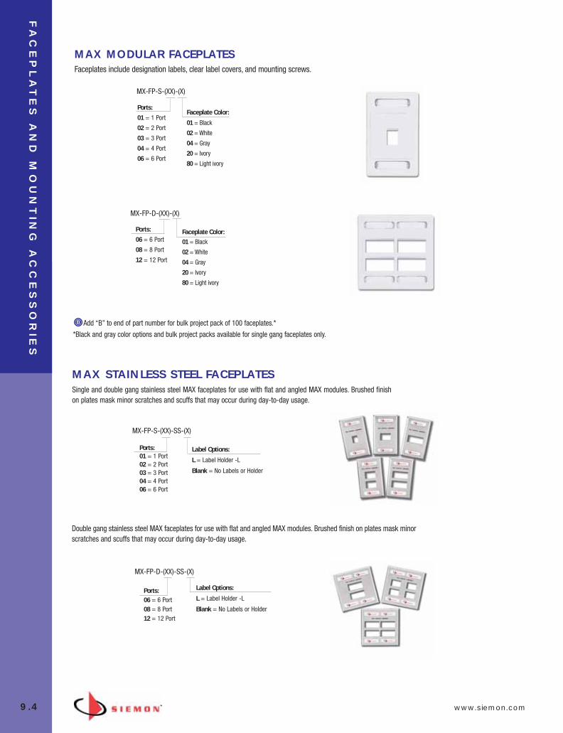
FA
CE
PL
AT
ES
AN
D M
OU
NT
ING
AC
CE
SS
OR
IES
9.4 www.siemon.com
MAX STAINLESS STEEL FACEPLATESSingle and double gang stainless steel MAX faceplates for use with flat and angled MAX modules. Brushed finishon plates mask minor scratches and scuffs that may occur during day-to-day usage.
01 = Black
02 = White
04 = Gray
20 = Ivory
80 = Light ivory
Faceplate Color:
MAX MODULAR FACEPLA TESFaceplates include designation labels, clear label covers, and mounting screws.
MX-FP-S-(XX)-(X)
Add “B” to end of part number for bulk project pack of 100 faceplates.*
*Black and gray color options and bulk project packs available for single gang faceplates only.
MX-FP-S-(XX)-SS-(X)
Label Options:
L = Label Holder -L
Blank = No Labels or Holder
Ports:06 = 6 Port08 = 8 Port12 = 12 Port
MX-FP-D-(XX)-SS-(X)
Label Options:
L = Label Holder -L
Blank = No Labels or Holder
Double gang stainless steel MAX faceplates for use with flat and angled MAX modules. Brushed finish on plates mask minorscratches and scuffs that may occur during day-to-day usage.
01 = Black
02 = White
04 = Gray
20 = Ivory
80 = Light ivory
Faceplate Color:
MX-FP-D-(XX)-(X)
Ports:
01 = 1 Port
02 = 2 Port
03 = 3 Port
04 = 4 Port
06 = 6 Port
Ports:
06 = 6 Port
08 = 8 Port
12 = 12 Port
Ports:01 = 1 Port02 = 2 Port03 = 3 Port04 = 4 Port06 = 6 Port
09_FP_Mounting.qxd:ZMax_Catalog 2/12/10 4:11 PM Page 5

www.siemon.com
FA
CE
PL
AT
ES
AN
D M
OU
NT
ING
AC
CE
SS
OR
IES
9.5
MAX INTERNATIONAL FACEPLATES Siemon’s Single-Gang horizontal Australian/Italian faceplate for Z-MAX, TERA or MAX modules
10G MAX® INTERNATIONAL FACEPLATESSiemon’s 10G Single-Gang horizontal Australian/Italian faceplate for Z-MAX, TERA or MAX modules
Add “B” to end of part number for bulk project pack of 100 faceplates.
MX-AD-(XX) . . . . . . . . . . . . . .
Door assembly for angled MAX modules,
bag of 20
MX-FD-(XX). . . . . . . . . . . . . . .
Door assembly for flat MAX modules, bag of 20
MX-BL-(XX). . . . . . . . . . . . . . .
Blank module,bag of 10
MAX OUTLET BLANKS AND DOORS Blank inserts for unused ports and future growth and doors to protect outlets from outside contaminants.
Use (XX) to specify color: 00 = clear (MX-AD-XX only), 01 = black, 02 = white, 04 = gray, 20 = ivory, 25 = bright white*, 80 = light ivory*Angled doors not available in bright white. Recommend using clear or white if required.
Ports:
01 = 1 Port
02 = 2 Port
03 = 3 Port
10GMX-HFP-(XX)(X)
Color:
02 = White
20 = Ivory
80 = Light Ivory
Ports:
01 = 1 Port
02 = 2 Port
03 = 4 Port
04 = 3 Port
MX-HFP-(XX)(X)
Color:
02 = White
20 = Ivory
80 = Light Ivory
Screws, metal mounting plate, designation label and clear label cover included.
Note: Door assemblies not compatible with Z-MAX outlets
09_FP_Mounting.qxd:ZMax_Catalog 2/12/10 4:11 PM Page 6

FA
CE
PL
AT
ES
AN
D M
OU
NT
ING
AC
CE
SS
OR
IES
9.6 www.siemon.com
MX-MFP-(XX). . . . . . . . . . . . . . .
Modular furniture adapter for standard openings including steelcase
Use (XX) to specify color: 01 = black, 02 = white, 04 = gray,20 = ivory, 80 = light ivory
MX-MFP-KNL-01. . . . . . . . . . . .
Modular furniture adapter for Knoll Groupopenings, black
MX-MFP-HME-01 . . . . . . . . . . .
Modular furniture adapter for Herman MillerEthospace Beltline openings,black
MX-MFP-HMA-(XX) . . . . . . . . . .
Modular furniture adapter for Herman Miller Action Office Series 2 andEthospace base openings
Use (XX) to specify color: 01 = black,02 = white, 04 = gray, 20 = ivory,
MX-MFP-AO3-(XX). . . . . . . . . . .
Modular furniture adapter for Herman Miller Action Office Series 3 baseopening
Use (XX) to specify color: 01 = black, 02 = white
Panel CutoutRequirements
34.16 – 35.69mm(1.345 – 1.405 in.)
67.46 – 69.85mm(2.656 – 2.750 in.)
Panel thickness: 0.76 – 2.03mm(0.030 – 0.080 in.)
Panel CutoutRequirements
45.47mm(1.79 in.)
73.15mm(2.88 in.)
Panel thickness: 1.24mm(0.05 in.)
Panel CutoutRequirements
47.80mm(1.882 in.)
75.74mm(2.982 in.)
Panel thickness: 1.52mm(0.060 in.)
Panel CutoutRequirements
48.26mm(1.90 in.)
76.86mm(3.026 in.)
Panel thickness: 0.76 – 2.03mm(0.030 – 0.080 in.)
Panel CutoutRequirements
44.45mm(1.750 in.)
72.01mm(2.835 in.)
Panel thickness: 2.41mm(0.095 in.)
MAX Modular Furniture adapters mount intomodular furniture openings, combining superior
density with proper circuit designation.
MAX® MODULAR FURNITURE ADAPTERSThe MAX modular furniture adapters will accept four Z-MAX hybrid outlets, MAX angled or flat modulesand snaps directly into communication outlet openings* in most major modular furniture systems,including Steelcase, Haworth and Herman Miller. Adapters include designation label and clear labelcover to allow for circuit identification.
Note: For Herman Miller Action Office Series 3 152mm (6 in.) vertical panel, use our MX-FP-S-(XX)-(XX) to mount up to six outlets.
*Furniture outlet openings, panel thickness, and raceway clearance may vary. Please consult furniture manufacturer for actual dimensions to determine compatibility.
ACCESSORIES
Part # Description
CT-FP-LBL-104* . . . . . . . . . . . . 10 sheets of labels for faceplates that will fit any standard 8.5 x 11 printer, 104 labels/sheet
MX-FP-CVR-00 . . . . . . . . . . . . . Bag of 100 clear label covers for MAX faceplates
*Visit our web site or contact our Technical Support Department for labeling software.
Add “B” for bulk pack of 100 icons or tabs.
09_FP_Mounting.qxd:ZMax_Catalog 2/12/10 4:11 PM Page 7
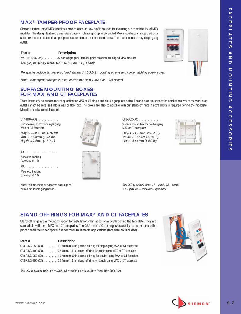
www.siemon.com
FA
CE
PL
AT
ES
AN
D M
OU
NT
ING
AC
CE
SS
OR
IES
9.7
MAX® TAMPER-PROOF FACEPLATESiemon’s tamper-proof MAX faceplates provide a secure, low profile solution for mounting our complete line of MAXmodules. The design features a one-piece base which accepts up to six angled MAX modules and is secured by asolid cover and a choice of tamper-proof star or standard slotted head screw. The base mounts to any single gangoutlet.
Part # DescriptionMX-TFP-S-06-(XX). . . . . . . . . . . 6-port single gang, tamper-proof faceplate for angled MAX modules
Use (XX) to specify color: 02 = white, 80 = light ivory
Faceplates include tamper-proof and standard #6-32x1 mounting screws and color-matching screw cover.
SURFACE MOUNTING BOXES FOR MAX AND CT FACEPLATESThese boxes offer a surface mounting option for MAX or CT single and double gang faceplates. These boxes are perfect for installations where the work areaoutlet cannot be recessed into a wall or floor box. The boxes are also compatible with our stand-off rings if extra depth is required behind the faceplate.Mounting hardware not included.
CT4-BOX-(XX) . . . . . . . . . . . . . .
Surface mount box for single gangMAX or CT faceplate
height: 119.3mm (4.70 in), width: 74.8mm (2.95 in), depth: 40.6mm (1.60 in)
CT8-BOX-(XX) . . . . . . . . . . . . . .
Surface mount box for double gangMAX or CT faceplate
height: 119.3mm (4.70 in),width: 120.8mm (4.76 in), depth: 40.6mm (1.60 in)
AB . . . . . . . . . . . . . . . . . . . . . . .
Adhesive backing (package of 10)
MB . . . . . . . . . . . . . . . . . . . . . .
Magnetic backing (package of 10)
Note: Two magnetic or adhesive backings re-quired for double gang boxes.
Use (XX) to specify color: 01 = black, 02 = white,04 = gray, 20 = ivory, 80 = light ivory
STAND-OFF RINGS FOR MAX® AND CT FACEPLATES Stand-off rings are a mounting option for installations that need extra depth behind the faceplate. They arecompatible with both MAX and CT faceplates. The 25.4mm (1.00 in.) ring is especially useful to ensure theproper bend radius for optical fiber or other multimedia applications (faceplate not included).
Part # DescriptionCT4-RING-050-(XX) . . . . . . . . . . 12.7mm (0.50 in.) stand-off ring for single gang MAX or CT faceplate
CT4-RING-100-(XX) . . . . . . . . . . 25.4mm (1.0 in.) stand-off ring for single gang MAX or CT faceplate
CT8-RING-050-(XX) . . . . . . . . . . 12.7mm (0.50 in.) stand-off ring for double gang MAX or CT faceplate
CT8-RING-100-(XX) . . . . . . . . . . 25.4mm (1.0 in.) stand-off ring for double gang MAX or CT faceplate
Use (XX) to specify color: 01 = black, 02 = white, 04 = gray, 20 = ivory, 80 = light ivory
Note: Tamperproof faceplate is not compatible with Z-MAX or TERA outlets.
09_FP_Mounting.qxd:ZMax_Catalog 2/12/10 4:11 PM Page 8

FA
CE
PL
AT
ES
AN
D M
OU
NT
ING
AC
CE
SS
OR
IES
9.8 www.siemon.com
Snap-on Cover with Designation Areas —For color-coded icons/tabs and write-on labels
Cable/Raceway Entry — Breakouts on three sides and bottom
Cable Tie Anchor Points — Facilitates strain relief for cable
MAX Bezels Included — Allows flat MAX modules to be securedin place
Optional Spring-loaded Shutter Doors — Shutter doors offeradded protection from dust and other contaminants
Label Cover — Conceals screw for added security if desired
Cable Management — Built-in cable management featuresensure proper bend radius for copper or fiber
1
Surface mount boxes feature a sleek compact, easy-to-install design. UTP, shielded, fiber, video, and coaxMAX® modules, Z-MAX or TERA® outlets can be quickly installed into the base. Multiple cable managementfeatures provide a high performance and well organized installation.
2
3
4
5
6
7
1
2
3
45
6
7
Z-MAX (MX-SMZ) SURFACE MOUNT BOXES
Color02 - White20 - Ivory80 - Light Ivory
Ports2 - 2 port*4 - 4 port*6 - 6 port*
MX-SMZ(X)-(XX) . . . . . . . . . . . . Z-MAX Surface mount box with cover base, 2 port multimedia bezel, cable ties, adhesive tape and mounting screws
Surface Mount Boxes
* Includes designation labels and label coversAdd “-M” for optional magnets.
09_FP_Mounting.qxd:ZMax_Catalog 2/12/10 4:11 PM Page 9

www.siemon.com
FA
CE
PL
AT
ES
AN
D M
OU
NT
ING
AC
CE
SS
OR
IES
9.9
MX-SM SURFACE MOUNT BOXESField-assembled surface mount boxes with MAX bezels. Accepts flat MAX modules or TERA outlets ordered separately.
MX-SM1-(XX) . . . . . . . . . . . . . . . . . . . . . . . . . . . . . . . . . . . . . . . . . . . . .
1-port box with cover, base, one single port MAX bezel, cable ties, adhesive tape and mounting screws
MX-SM2-(XX) . . . . . . . . . . . . . . . . . . . . . . . . . . . . . . . . . . . . . . . . . . . . .
2-port box with cover, base, one (2-port) MAX bezel, cable ties, adhesive tape, mounting screws, and designation labels
MX-SM4-(XX) . . . . . . . . . . . . . . . . . . . . . . . . . . . . . . . . . . . . . . . . . . . . .
4-port box with cover, base, two (2-port) MAX bezels, cable ties, adhesive tape, mounting screws, designation labels and labelcovers
MX-SM6-(XX) . . . . . . . . . . . . . . . . . . . . . . . . . . . . . . . . . . . . . . . . . . . . .
6-port box with cover, base, three (2-port) MAX bezels, cable ties, adhesive tape, mounting screws, designation labels and labelcovers
Use (XX) to specify color: 01 = black, 02 = white, 20 = ivory, 80 = light ivory.
Add “-D” for optional spring shutter doors.
Add “-M” for optional magnets.
Add “-MD” for optional doors and magnets.
Use (XX) to specify color: 01 = black, 02 = white, 20 = ivory, 80 = light ivory.
*SC adapters are “universal” to support both multimode and singlemode.
MX-SMB-MM-(XX) . . . . . . . . . . . . . . . 2-port multimedia bezel
Note: Multimedia bezels accommodate Z-MAX, TERA outlets and flat MAX duplex LC adapters. They are also compatible with all other single port flat MAX modules, but require the use of icons to secure modules into bezel.
MAX bezels are compatible with all single port, flat MAX modules. For LC, SC duplex fiberadapters Z-MAX and TERA options, see MX-SM multimedia bezels below.
MX-SMB-SC-(XX). . . . . . . . . . . . . . . . 2-port bezel with one duplex SC adapter*
MX-SM-BLNK-(XX). . . . . . . . . . . . . . . 1-port blank insert for MAX bezels
MX-SM MULTIMEDIA BEZELS AND COMPONENTS
09_FP_Mounting.qxd:ZMax_Catalog 2/12/10 4:11 PM Page 10
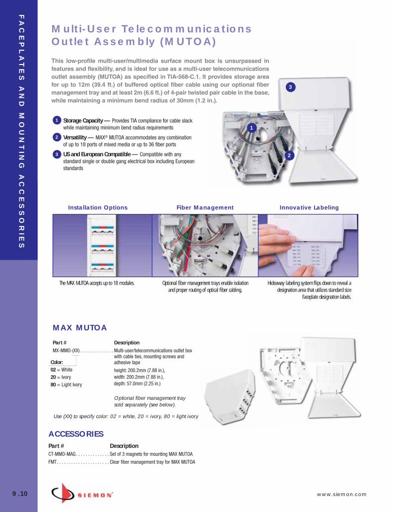
FA
CE
PL
AT
ES
AN
D M
OU
NT
ING
AC
CE
SS
OR
IES
9.10 www.siemon.com
MAX MUTOA
Installation Options Fiber Management Innovative Labeling
The MAX MUTOA accepts up to 18 modules. Optional fiber management trays enable isolationand proper routing of optical fiber cabling.
Hideaway labeling system flips down to reveal adesignation area that utilizes standard size
faceplate designation labels.
Storage Capacity — Provides TIA compliance for cable slackwhile maintaining minimum bend radius requirements
Versatility — MAX® MUTOA accommodates any combinationof up to 18 ports of mixed media or up to 36 fiber ports
US and European Compatible — Compatible with anystandard single or double gang electrical box including Europeanstandards
1
2
3
1
2
3
Part # DescriptionMX-MMO-(XX) . . . . . . . . . . . . . . Multi-user/telecommunications outlet box
with cable ties, mounting screws andadhesive tape
height: 200.2mm (7.88 in.), width: 200.2mm (7.88 in.), depth: 57.0mm (2.25 in.)
Optional fiber management traysold separately (see below).
Use (XX) to specify color: 02 = white, 20 = ivory, 80 = light ivory
ACCESSORIESPart # DescriptionCT-MMO-MAG . . . . . . . . . . . . . . Set of 3 magnets for mounting MAX MUTOA
FMT. . . . . . . . . . . . . . . . . . . . . . Clear fiber management tray for MAX MUTOA
This low-profile multi-user/multimedia surface mount box is unsurpassed infeatures and flexibility, and is ideal for use as a multi-user telecommunicationsoutlet assembly (MUTOA) as specified in TIA-568-C.1. It provides storage areafor up to 12m (39.4 ft.) of buffered optical fiber cable using our optional fibermanagement tray and at least 2m (6.6 ft.) of 4-pair twisted pair cable in the base,while maintaining a minimum bend radius of 30mm (1.2 in.).
Multi-User TelecommunicationsOutlet Assembly (MUTOA)
Color:02 = White20 = Ivory80 = Light Ivory
09_FP_Mounting.qxd:ZMax_Catalog 2/12/10 4:11 PM Page 11

www.siemon.com
FA
CE
PL
AT
ES
AN
D M
OU
NT
ING
AC
CE
SS
OR
IES
9.11
FIBER OUTLET BOX (FOB2)Siemon’s low-profile Fiber Outlet Box (FOB2) is the optimal solution for bringing fiber to the desk. The FOB2 offers a well-defined method formanaging fiber cabling at the work area by providing a connection point for up to 12 fibers connectors utilizing slide-in bezels.
FOB2-(XX) . . . . . . . . . . . . . . . . . Includes base, cover, designation labels, clearlabel covers, mounting hardware, cable ties,icons, and three blank bezels
FOB2-GRD-(XX) . . . . . . . . . . . . . Includes base, extended cover, designation labels, clear label covers, mountinghardware, cable ties, icons, and three blankbezels
FIBER BEZELSUse (XX) to specify color: 01 = black, 02 = white, 80 = light ivory
Use (X) to specify LC adapter color: blank = beige, U = blue*Note: Fiber adapters are “universal” to support both multimode and singlemode.
FOB-BZL-SC-01 . . . . . . . . . . .
1 Duplex SC adapter, (2 fibers)*
FOB-BZL-LC(X)1-01 . . . . . . . .
1 Duplex LC adapter, (2 fibers)
FOB-BZL-SA-01 . . . . . . . . . . .
1 Duplex ST adapter, (2 fibers)*
FOB-BZL-LC(X)-01 . . . . . . . . .
2 Duplex LC adapters, (4 fibers)
FOB-BZL-BL-01 . . . . . . . . . . .
Blank bezel
XGLO® & LIGHTSYSTEM®
LIGHTSYSTEM
09_FP_Mounting.qxd:ZMax_Catalog 2/12/10 4:12 PM Page 12

FA
CE
PL
AT
ES
AN
D M
OU
NT
ING
AC
CE
SS
OR
IES
9.12 www.siemon.com
CT FACEPLATES
CT2-FP-(XX) . . . . . . . . . . . .
1-port single gang plasticfaceplate for a CT adapter
CT4-FP-(XX) . . . . . . . . . . . .
2-port single gang plasticfaceplate for CT adapters
CT8-FP-(XX) . . . . . . . . . . . .
4-port double gang plasticfaceplate for CT adapters
CT2-HFPA-(XX)*. . . . . . . . . .
1-port single gang plastichorizontal faceplate for a CTadapter, with color matchingscrew caps
TERA®-MAX® ADAPTERS FOR CT FACEPLATESDesigned for use in standard CT faceplates or adapters, adapters feature angled bezel orientation to reduce mounting depthrequirements for TERA and flat MAX outlets and facilitates gravity feed installation design.
CTE-MXA-01-02. . . . . . . 1-port angled CT adapterfor a UTP MAX module, Z-MAX or TERA outlet,white
CTE-MXA-02-02. . . . . . . 2-port angled CT adapterfor UTP MAX modules, Z-MAX or TERA outlets,white
Use (XX) to specify color: 02 = white, 20 = ivory, 80 = light ivoryFaceplates include designation label(s), label cover(s) and #6-32x1 screws.
Add “B” to end of part number for bulk project pack, (includes 100 CT2 or CT4 faceplates or 50 CT8 faceplates, screws,designation labels, and label covers).*Not available in bulk project pack.
CT MODULAR FURNITURE ADAPTERS
CT-MFP-(XX) . . . . . . . . . . . . . . .
Adapter for standard openings includingSteelcase (accepts one CT coupler)
Use (XX) to specify color: 01 = black, 02 = white, 04 = gray, 20 = ivory, 80 = light ivory
CT-MFP-HMA-(XX) . . . . . . . . . . .
Adapter for Herman Miller Action OfficeSeries 2 and Ethospace base openings(accepts two CT couplers)
Use (XX) to specify color: 01 = black, 02 = white
Use (XX) to specify color: 01 = black, 02 = white, 04 = gray, 20 = ivory, 80 = light ivory
For CT Coupler options, visit our web site or contact our Customer Service Department
For CT Coupler options, visit our web site or contact our Customer Service Department
09_FP_Mounting.qxd:ZMax_Catalog 2/12/10 4:12 PM Page 13

www.siemon.com
FA
CE
PL
AT
ES
AN
D M
OU
NT
ING
AC
CE
SS
OR
IES
9.13
09_FP_Mounting.qxd:ZMax_Catalog 2/12/10 4:12 PM Page 14
Ve
rs
aP
OD
™ R
AC
KS
AN
D C
AB
LE
MA
NA
GE
ME
NT
10.0 www.siemon.com
SECTION CONTENTS
VersaPOD Features and Benefits . . . . . . . . . . . . . . . . . . . . . . . . . . . . 10.1
VersaPOD Ordering Information . . . . . . . . . . . . . . . . . . . . . . . 10.2 – 10.4
RS3 Cable Management Rack System . . . . . . . . . . . . . . . . . 10.5 – 10.6
RS3 Series Horizontal Cable Managers . . . . . . . . . . . . . . . . . . . . . . . 10.6
RS Rack System . . . . . . . . . . . . . . . . . . . . . . . . . . . . . . . . . . 10.7 – 10.8
Extended Depth RS Rack System . . . . . . . . . . . . . . . . . . . . . . . . . . . 10.8
RS Series Horizontal Cable Managers . . . . . . . . . . . . . . . . . . . . . . . . .10.8
Vertical Patching Channel (VPC) . . . . . . . . . . . . . . . . . . . . . 10.9 – 10.10
Vertical Cable Management Channels . . . . . . . . . . . . . . . . . . . . . . . 10.10
Rack Accessories . . . . . . . . . . . . . . . . . . . . . . . . . . . . . . . . . . . . . . 10.11
S110®/S210® Horizontal Cable Managers . . . . . . . . . . . . . . . . . . . . 10.11
Rear Cable Manager . . . . . . . . . . . . . . . . . . . . . . . . . . . . . . . . . . . . 10.11
WM Series Horizontal Cable Managers . . . . . . . . . . . . . . . . . . . . . . 10.12
Cable Hangers . . . . . . . . . . . . . . . . . . . . . . . . . . . . . . . . . . . . . . . . . 10.12
Stand-Off Brackets . . . . . . . . . . . . . . . . . . . . . . . . . . . . . . . . . . . . . 10.12
Siemon offers a comprehensive family of data center cabinets,equipment racks and cable management products to support nearly any infrastructure.
This family includes:
• The innovative VersaPOD data center cabinet, featuring space-saving Zero-U vertical patching and cable management
• RS3 and RS open rack systems with integrated cable man-agement features
• Vertical Patching Channels (VPC), designed to mount be-tween racks to provide an easily managed cable routing andmanagement solution
• A wide array of horizontal cable management options
10_RCM.qxd:RCM 1/26/10 2:27 PM Page 1

www.siemon.com
Ve
rs
aP
OD
™ R
AC
KS
AN
D C
AB
LE
MA
NA
GE
ME
NT
10.1
Siemon’s VersaPOD enables a completely new and efficient approach to your physical data center infrastructure. By leveraging the vertical space between bayedcabinets and at the end of row for patching, power distribution and cable manage-ment, the V-POD frees critical horizontal space for active equipment, providing im-proved air flow and the ultimate density in the minimum floor space.
The VersaPOD’s innova-tive Zero-U vertical patchpanels (VPP’s) dramati-cally simplify even themost dense patchingneeds while its verticalpatching channels (VPC)offer a clean, orderly andeasily manageablemethod of high-densitycable routing.
All of the VersaPOD’sunique features are integrated into a full-fea-tured modular enclosurethat is equally effective asa standalone cabinet or ina multi-unit bayed configuration, offering asimple, scalable expansion path in anydata center.
VersaPOD™ Features and Benefits
Vertical Patching – Vertical copperand fiber patch panels provide up to24U (12U at front and 12U at rear) ofZero-U vertical patching spacebetween every two cabinets. Thesepanels conveniently slide forwardproviding access to the connections atthe rear of the panel
End of Row – End of row verticalpanels offer additional cablemanagement channels or up to 8Uadditional Zero-U mounting space(4Uin front and 4U in back at each end)
Integration – In addition to patching,the VersaPOD’s Zero-U vertical spacecan be leveraged with integrated cablemanagement options and dual-hingeddoor to offer a high capacity andconcealable pathway for cable routingand slack management.
Cable Management – Vertical cablemanagement fingers can be mountedalongside each VPP or VPC tofacilitate routing of copper or fiberjumpers between patching fields aswell as cabinet to cabinet connections.
Dual Hinged Doors – Dual hingedfront and quad hinged rear doors openfrom either the left or right and areeasily removed. Rear split doors canbe hinged open in both directionsproviding direct access to verticalspaces. For standalone cabinets or endunits, side panels can be removed forfull side access.
1
1
2
4
5
2
3
4
5
3
10_RCM.qxd:RCM 1/26/10 2:27 PM Page 2

Ve
rs
aP
OD
™ R
AC
KS
AN
D C
AB
LE
MA
NA
GE
ME
NT
10.2 www.siemon.com
Part # Description
VP-DRA . . . . . . . . . . . . . . . . .Full vented door, dual handle with standard keyed lock
VP-DRB . . . . . . . . . . . . . . . . .Split vented door, dual handle with standard keyed lock(2 doors required to close front or rear of single cabinet)
VP-S . . . . . . . . . . . . . . . . . . .Locking Side Panel (standard keyed lock)
VP-DRC . . . . . . . . . . . . . . . . .Split solid door, dual handle with standard keyed lock (2 doors required to close front or rear of single cabinet)
CABINET DOORS AND PANELS
Includes: 4 leveling feet, 50 cage nuts and 4 stabilizing brackets
VP-VPP-TMRIC VP-VPP-TM VP-VPP-6U
VersaPOD™ Ordering Information
CABINET BASE UNIT
VP(X)-(X)(X)(X)(X)11
Side Panels0 = No Side Panels1 = 1 Side Panel2 = 2 Side Panels
Front Door
A = Full Vented/Dual HandleB = Split Vented/Dual HandleC = Split Solid/Dual Handle
Rear Door
A =Full Vented/Dual HandleB = Split Vented/Dual HandleC = Split Solid/Dual Handle
Lock1 = Keyed Lock2 = Tumbler Combination Lock
ZERO-U SLIDING VERTICAL PATCH PANELSPart # Description
VP-VPP-TMRIC . . . . . . . . . . . .Sliding Vertical Copper/Fiber Combo Patch Panel
- 96 Ports, support all category 5e and category 6 UTP MAX and Z-MAX, category
6A shielded Z-MAX outlets, TERA® outlets and MAX fiber adaptors. (Not for use
w/Z-MAX 6A UTP)
6 fiber RIC adaptor mounting spaces for mounting RIC adapter plates or fiber
plug and play modules
VP-VPP-TM . . . . . . . . . . . . . .Sliding Vertical Copper Patch Panel- 96 Ports, supports all category 5e category 6, category 6A UTP MAX and Z-MAX
outlets, category 6A shielded Z-MAX, TERA outlets and MAX fiber adaptors (Portspacing compatible with Z-MAX 6A UTP)
VP-VPP-6U . . . . . . . . . . . . . .Sliding Vertical Bracket for any Standard 19” Patch Panel - Mounts up to (6) 1U panels in Zero-U vertical
orientation
NOTE: 2 Vertical Panels can be mounted vertically at the front and/or rear of 2 bayed cabinets
1 = 1000 mm x 760 mm, 45U Black2 = 1200 mm x 760 mm, 45U Black
Dimensions
10_RCM.qxd:RCM 1/26/10 2:27 PM Page 3
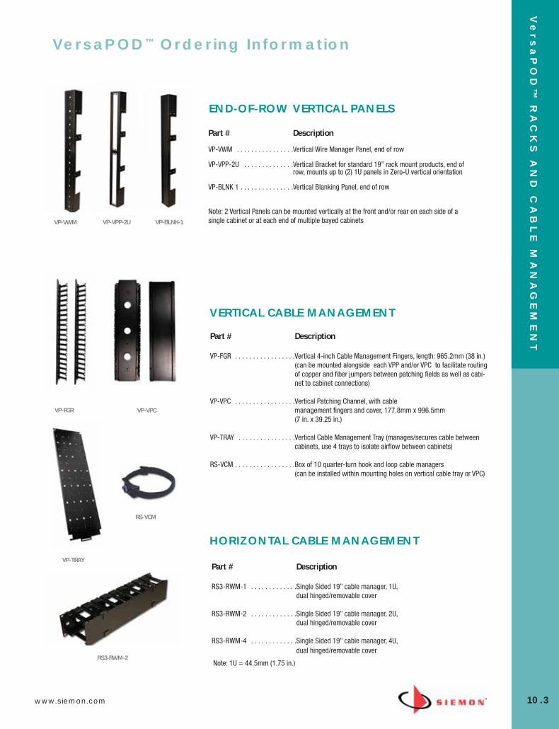
www.siemon.com
Ve
rs
aP
OD
™ R
AC
KS
AN
D C
AB
LE
MA
NA
GE
ME
NT
10.3
Part # Description
VP-FGR . . . . . . . . . . . . . . . . .Vertical 4-inch Cable Management Fingers, length: 965.2mm (38 in.)(can be mounted alongside each VPP and/or VPC to facilitate routingof copper and fiber jumpers between patching fields as well as cabi-net to cabinet connections)
VP-VPC . . . . . . . . . . . . . . . . .Vertical Patching Channel, with cable management fingers and cover, 177.8mm x 996.5mm (7 in. x 39.25 in.)
VP-TRAY . . . . . . . . . . . . . . . .Vertical Cable Management Tray (manages/secures cable betweencabinets, use 4 trays to isolate airflow between cabinets)
RS-VCM . . . . . . . . . . . . . . . . .Box of 10 quarter-turn hook and loop cable managers (can be installed within mounting holes on vertical cable tray or VPC)
VP-FGR VP-VPC
VP-TRAY
HORIZONTAL CABLE MANAGEMENT
Part # Description
RS3-RWM-1 . . . . . . . . . . . . .Single Sided 19” cable manager, 1U, dual hinged/removable cover
RS3-RWM-2 . . . . . . . . . . . . .Single Sided 19” cable manager, 2U, dual hinged/removable cover
RS3-RWM-4 . . . . . . . . . . . . .Single Sided 19” cable manager, 4U, dual hinged/removable cover
RS3-RWM-2
RS-VCM
VersaPOD™ Ordering Information
VERTICAL CABLE MANAGEMENT
VP-VWM VP-VPP-2U VP-BLNK-1
Part # Description
VP-VWM . . . . . . . . . . . . . . . .Vertical Wire Manager Panel, end of row
VP-VPP-2U . . . . . . . . . . . . . .Vertical Bracket for standard 19” rack mount products, end ofrow, mounts up to (2) 1U panels in Zero-U vertical orientation
VP-BLNK 1 . . . . . . . . . . . . . . .Vertical Blanking Panel, end of row
END-OF-ROW VERTICAL PANELS
Note: 2 Vertical Panels can be mounted vertically at the front and/or rear on each side of asingle cabinet or at each end of multiple bayed cabinets
Note: 1U = 44.5mm (1.75 in.)
10_RCM.qxd:RCM 1/26/10 2:27 PM Page 4
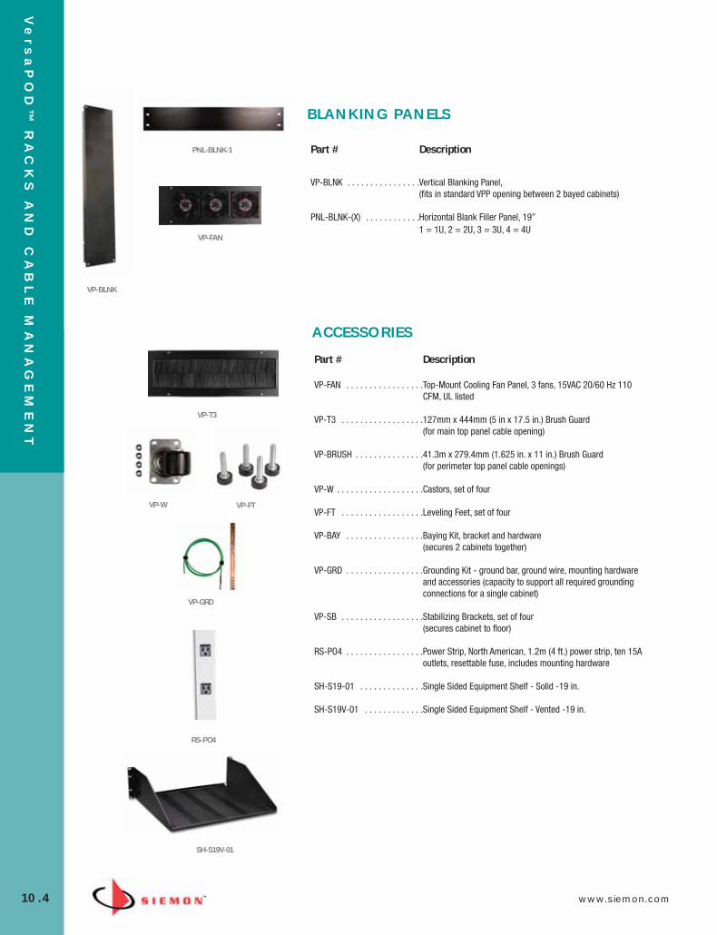
Ve
rs
aP
OD
™ R
AC
KS
AN
D C
AB
LE
MA
NA
GE
ME
NT
10.4 www.siemon.com
Part # Description
VP-BLNK . . . . . . . . . . . . . . . .Vertical Blanking Panel, (fits in standard VPP opening between 2 bayed cabinets)
PNL-BLNK-(X) . . . . . . . . . . . .Horizontal Blank Filler Panel, 19”1 = 1U, 2 = 2U, 3 = 3U, 4 = 4U
VP-W VP-FT
VP-GRD
Part # Description
VP-FAN . . . . . . . . . . . . . . . . .Top-Mount Cooling Fan Panel, 3 fans, 15VAC 20/60 Hz 110CFM, UL listed
VP-T3 . . . . . . . . . . . . . . . . . .127mm x 444mm (5 in x 17.5 in.) Brush Guard (for main top panel cable opening)
VP-BRUSH . . . . . . . . . . . . . . .41.3m x 279.4mm (1.625 in. x 11 in.) Brush Guard (for perimeter top panel cable openings)
VP-W . . . . . . . . . . . . . . . . . . .Castors, set of four
VP-FT . . . . . . . . . . . . . . . . . .Leveling Feet, set of four
VP-BAY . . . . . . . . . . . . . . . . .Baying Kit, bracket and hardware (secures 2 cabinets together)
VP-GRD . . . . . . . . . . . . . . . . .Grounding Kit - ground bar, ground wire, mounting hardwareand accessories (capacity to support all required groundingconnections for a single cabinet)
VP-SB . . . . . . . . . . . . . . . . . .Stabilizing Brackets, set of four (secures cabinet to floor)
RS-PO4 . . . . . . . . . . . . . . . . .Power Strip, North American, 1.2m (4 ft.) power strip, ten 15Aoutlets, resettable fuse, includes mounting hardware
SH-S19-01 . . . . . . . . . . . . . .Single Sided Equipment Shelf - Solid -19 in.
SH-S19V-01 . . . . . . . . . . . . .Single Sided Equipment Shelf - Vented -19 in.
VP-FAN
VP-T3
VP-BLNK
RS-PO4
SH-S19V-01
BLANKING PANELS
ACCESSORIES
PNL-BLNK-1
10_RCM.qxd:RCM 1/26/10 2:27 PM Page 5
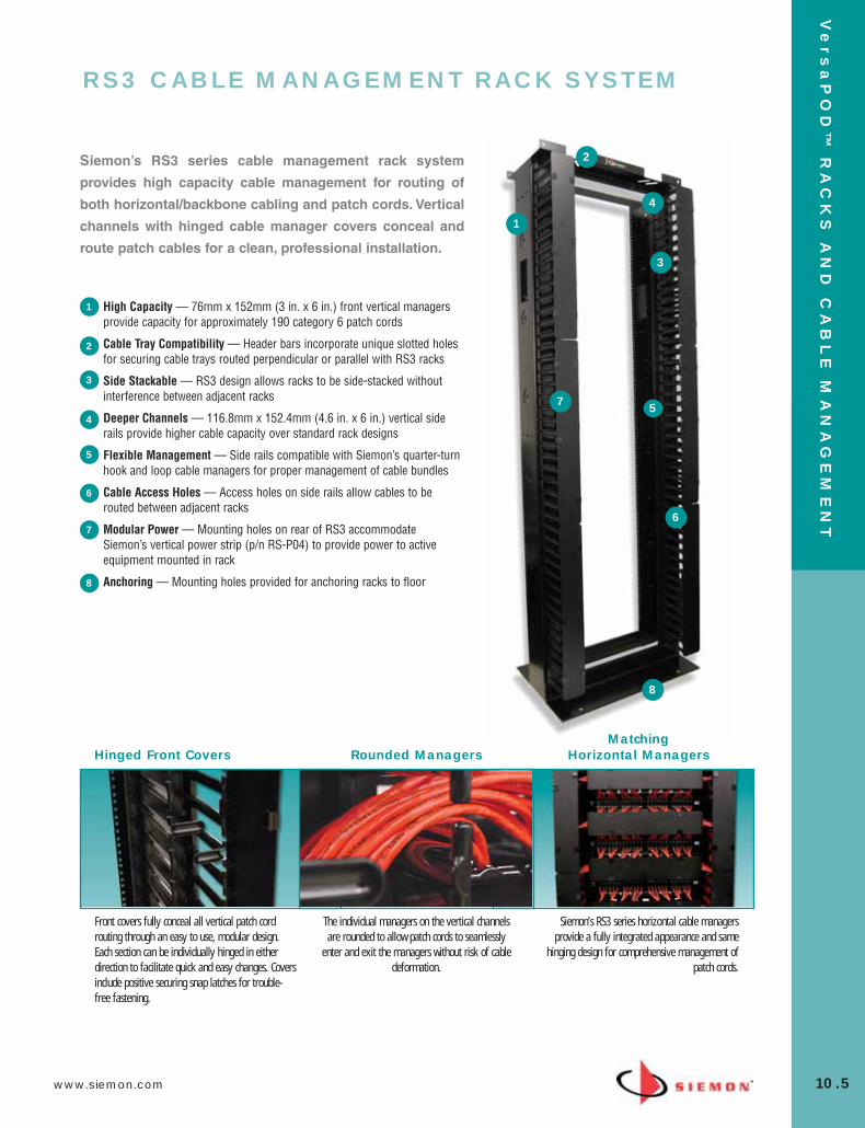
www.siemon.com
Ve
rs
aP
OD
™ R
AC
KS
AN
D C
AB
LE
MA
NA
GE
ME
NT
10.5
High Capacity — 76mm x 152mm (3 in. x 6 in.) front vertical managersprovide capacity for approximately 190 category 6 patch cords
Cable Tray Compatibility — Header bars incorporate unique slotted holesfor securing cable trays routed perpendicular or parallel with RS3 racks
Side Stackable — RS3 design allows racks to be side-stacked withoutinterference between adjacent racks
Deeper Channels — 116.8mm x 152.4mm (4.6 in. x 6 in.) vertical siderails provide higher cable capacity over standard rack designs
Flexible Management — Side rails compatible with Siemon’s quarter-turnhook and loop cable managers for proper management of cable bundles
Cable Access Holes — Access holes on side rails allow cables to berouted between adjacent racks
Modular Power — Mounting holes on rear of RS3 accommodateSiemon’s vertical power strip (p/n RS-P04) to provide power to activeequipment mounted in rack
Anchoring — Mounting holes provided for anchoring racks to floor
1
2
3
4
5
6
7
8
Siemon’s RS3 series cable management rack system
provides high capacity cable management for routing of
both horizontal/backbone cabling and patch cords. Vertical
channels with hinged cable manager covers conceal and
route patch cables for a clean, professional installation.
Hinged Front Covers Rounded ManagersMatching
Horizontal Managers
The individual managers on the vertical channelsare rounded to allow patch cords to seamlessly
enter and exit the managers without risk of cabledeformation.
Siemon’s RS3 series horizontal cable managersprovide a fully integrated appearance and same
hinging design for comprehensive management ofpatch cords.
Front covers fully conceal all vertical patch cordrouting through an easy to use, modular design.Each section can be individually hinged in eitherdirection to facilitate quick and easy changes. Coversinclude positive securing snap latches for trouble-free fastening.
1
2
3
4
5
6
7
8
RS3 CABLE MANAGEMENT RACK SYSTEM
10_RCM.qxd:RCM 1/26/10 2:27 PM Page 6

Ve
rs
aP
OD
™ R
AC
KS
AN
D C
AB
LE
MA
NA
GE
ME
NT
10.6 www.siemon.com
RS3 SERIES HORIZONTAL CABLE MANAGERSThese horizontal cable managers are designed for use with Siemon’s RS3 seriesracks and use the same hinged cover design as the vertical managers. The coverssnap easily over cable managers and provide a concealed routing path into thevertical cable management of the RS3 providing a clean patching environment.
Part # DescriptionRS3-RWM-1 . . . . . . . . . . . . . . . Single-sided 19 in. cable manager, 1U
height: 44.5mm (1.75 in.), width: 0.48m (19 in.), depth: 101.6mm (4 in.)
RS3-RWM-2 . . . . . . . . . . . . . . .Single-sided 19 in. cable manager, 2U
height: 88.9mm (3.5 in.), width: 0.48m (19 in.), depth: 101.6mm (4 in.)
RS3-RWM-2DS . . . . . . . . . . . . . Double-sided 19 in. cable manager, 2U
height: 88.9mm (3.5 in.), width: 0.48m (19 in.), depth: 203.2mm (8 in.)
RS3-RWM-4 . . . . . . . . . . . . . . . Single-sided 19 in. cable manager, 4U
height: 88.9mm (7.0 in.), width: 0.48m (19 in.), depth: 101.6mm (4 in.)
RS3 CABLE MANAGEMENT RACK SYSTEMPart # DescriptionRS3-07-S . . . . . . . . . . . . . . . . . 2.1m x 0.48m (7 ft. x 19 in.) steel enhanced cable
management rack system, 45U. Includes rack assemblyhardware, vertical cable management channels with hingedcovers, and ground lug
height: 2.1m (7 ft.),width: 685.0mm (27 in.),depth: 457.2mm (18 in.)
Note: Aluminum racks (RS3-07) are available and intended for use with connecting hardwareand cable managers only. For mounting of active equipment, steel racks are recommended.
RS3-RWM-1 RS3-RWM-2
See Cable Management Capacity Table in the Cable Management Section of our E-Catalog on our Web Site
Note: 1U = 44.5mm (1.75 in.)
Note: 1U = 44.5mm (1.75 in.)
See Cable Management Capacity Table in the Cable Management Section of our E-Catalog on our Web Site
RS3-RWM-2DS RS3-RWM-4
10_RCM.qxd:RCM 1/26/10 2:27 PM Page 7
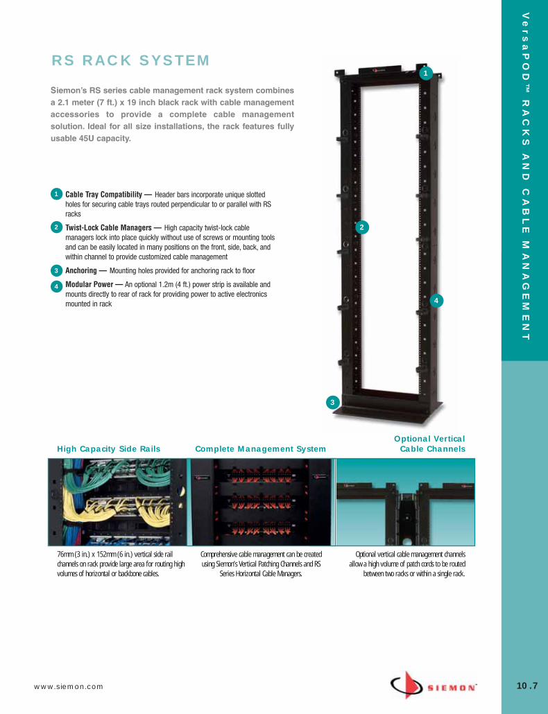
www.siemon.com
Ve
rs
aP
OD
™ R
AC
KS
AN
D C
AB
LE
MA
NA
GE
ME
NT
10.7
RS RACK SYSTEM
High Capacity Side Rails Complete Management SystemOptional Vertical
Cable Channels
Comprehensive cable management can be createdusing Siemon’s Vertical Patching Channels and RS
Series Horizontal Cable Managers.
Optional vertical cable management channelsallow a high volume of patch cords to be routed
between two racks or within a single rack.
76mm (3 in.) x 152mm (6 in.) vertical side railchannels on rack provide large area for routing highvolumes of horizontal or backbone cables.
Siemon’s RS series cable management rack system combinesa 2.1 meter (7 ft.) x 19 inch black rack with cable managementaccessories to provide a complete cable managementsolution. Ideal for all size installations, the rack features fullyusable 45U capacity.
Cable Tray Compatibility — Header bars incorporate unique slottedholes for securing cable trays routed perpendicular to or parallel with RSracks
Twist-Lock Cable Managers — High capacity twist-lock cablemanagers lock into place quickly without use of screws or mounting toolsand can be easily located in many positions on the front, side, back, andwithin channel to provide customized cable management
Anchoring — Mounting holes provided for anchoring rack to floor
Modular Power — An optional 1.2m (4 ft.) power strip is available andmounts directly to rear of rack for providing power to active electronicsmounted in rack
1
2
3
4
1
2
3
4
10_RCM.qxd:RCM 1/26/10 2:27 PM Page 8

Ve
rs
aP
OD
™ R
AC
KS
AN
D C
AB
LE
MA
NA
GE
ME
NT
10.8 www.siemon.com
RS RACK SYSTEMPart # DescriptionRS-07-S . . . . . . . . . . . . . . . . . . 2.1m x 0.48m (7 ft. x 19 in.) steel cable
management rack system, 45U. Includes: rack assembly hardware, 10 high-capacity cable managers, 10 hook and loop cable managers, grommets, and ground lug
height: 2.1m (7 ft.), width: 609.6mm (24 in.), depth: 457.2mm (18 in.)
Note: Aluminum racks are available (P/N: RS-07) and intended for use with connecting hardware andcable managers only. For mounting of active equipment, steel racks are recommended.
RS SERIES HORIZONTAL CABLE MANAGERSSiemon’s RS series cable managers are designed for use with Siemon’s RS-07 racks in conjunction with Siemon’svertical patching channel. The hinged cover extends across the vertical channels of the RS-07 to fully conceal patch cordsinto the Vertical Patching Channel (VPC).
Part # DescriptionRS-RWM-2 . . . . . . . . . . . . . . . .Single-sided 19 in. cable manager, 2U
height: 88.9mm (3.5 in.), width: 0.48m (19 in.), depth: 101.6mm (4 in.)
RS-RWM-2DS . . . . . . . . . . . . . . Double-sided 19 in. cable manager, 2U
height: 88.9mm (3.5 in.), 0.48m (19 in.), depth: 203.2mm (8 in.)
EXTENDED DEPTH RS RACK SYSTEMSiemon has developed a rack for managing extra large volumes of horizontal cables. The new extended depth rack featuresvertical channels which are 0.37m (14.5 in.) deep. These channels include multiple mounting holes allowing the user toconfigure Siemon’s twist-lock hook and loop cable managers for properly managing large individual bundles of cables. Thefooters have also been designed to retain the 0.61m (24 in.) overall footprint.
Part # DescriptionRS-07E . . . . . . . . . . . . . . . . . . . 2.1m x 0.48m (7 ft. x 19 in.) aluminum
extra-deep (0.37m [14.5 in]) cable management rack system, 45U. Includes rack assembly hardware, 10 high-capacity cable managers, 10 hook and loop managers, grommets and ground lug.
height: 2.1m (7 ft.), width: 609.6mm (24 in.), depth: 609.6mm (24 in.)
Note: Aluminum racks are intended for use with connecting hardware and cable managers only. For mounting of active equipment, steel racks such as RS-07-S are recommended.
RS-RWM-2
RS-RWM-2DS
See Cable Management Capacity Table in the Cable Management Section of our E-Catalog on our Web Site
See Cable Management Capacity Table in the Cable Management Section of our E-Catalog on our Web Site
See Cable Management Capacity Table in the Cable Management Section of our E-Catalog on our Web Site
10_RCM.qxd:RCM 1/26/10 2:28 PM Page 9
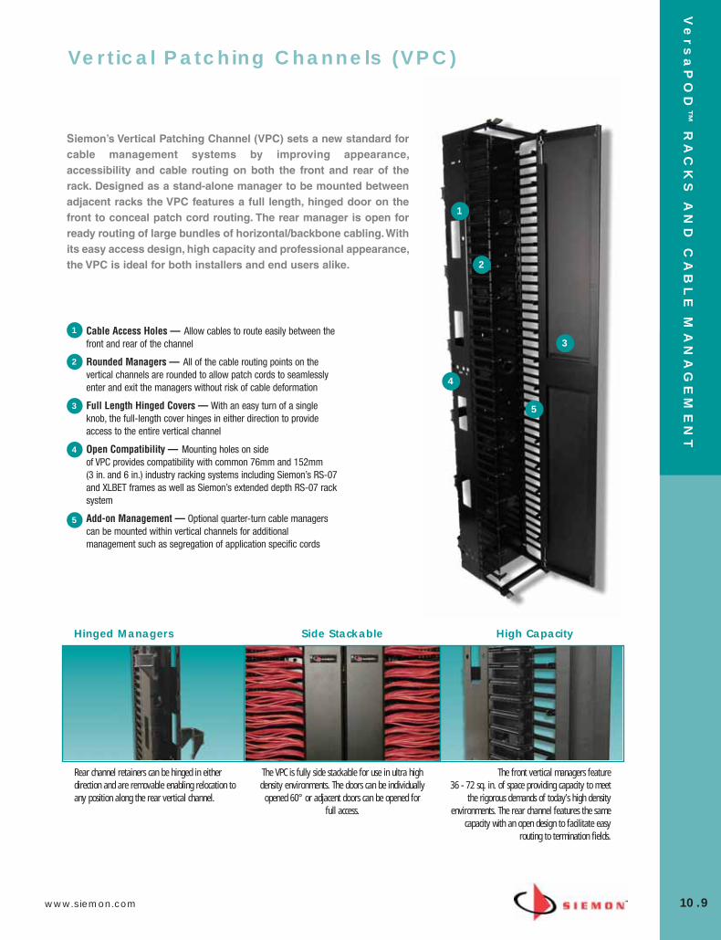
www.siemon.com
Ve
rs
aP
OD
™ R
AC
KS
AN
D C
AB
LE
MA
NA
GE
ME
NT
10.9
Cable Access Holes — Allow cables to route easily between thefront and rear of the channel
Rounded Managers — All of the cable routing points on thevertical channels are rounded to allow patch cords to seamlesslyenter and exit the managers without risk of cable deformation
Full Length Hinged Covers — With an easy turn of a singleknob, the full-length cover hinges in either direction to provideaccess to the entire vertical channel
Open Compatibility — Mounting holes on side of VPC provides compatibility with common 76mm and 152mm (3 in. and 6 in.) industry racking systems including Siemon’s RS-07and XLBET frames as well as Siemon’s extended depth RS-07 racksystem
Add-on Management — Optional quarter-turn cable managerscan be mounted within vertical channels for additionalmanagement such as segregation of application specific cords
Siemon’s Vertical Patching Channel (VPC) sets a new standard forcable management systems by improving appearance,accessibility and cable routing on both the front and rear of therack. Designed as a stand-alone manager to be mounted betweenadjacent racks the VPC features a full length, hinged door on thefront to conceal patch cord routing. The rear manager is open forready routing of large bundles of horizontal/backbone cabling. Withits easy access design, high capacity and professional appearance,the VPC is ideal for both installers and end users alike.
Hinged Managers Side Stackable High Capacity
The front vertical managers feature 36 - 72 sq. in. of space providing capacity to meet
the rigorous demands of today’s high densityenvironments. The rear channel features the same
capacity with an open design to facilitate easyrouting to termination fields.
Rear channel retainers can be hinged in eitherdirection and are removable enabling relocation toany position along the rear vertical channel.
The VPC is fully side stackable for use in ultra highdensity environments. The doors can be individually
opened 60° or adjacent doors can be opened forfull access.
1
2
3
4
5
1
2
3
4
5
Vertical Patching Channels (VPC)
10_RCM.qxd:RCM 1/26/10 2:28 PM Page 10
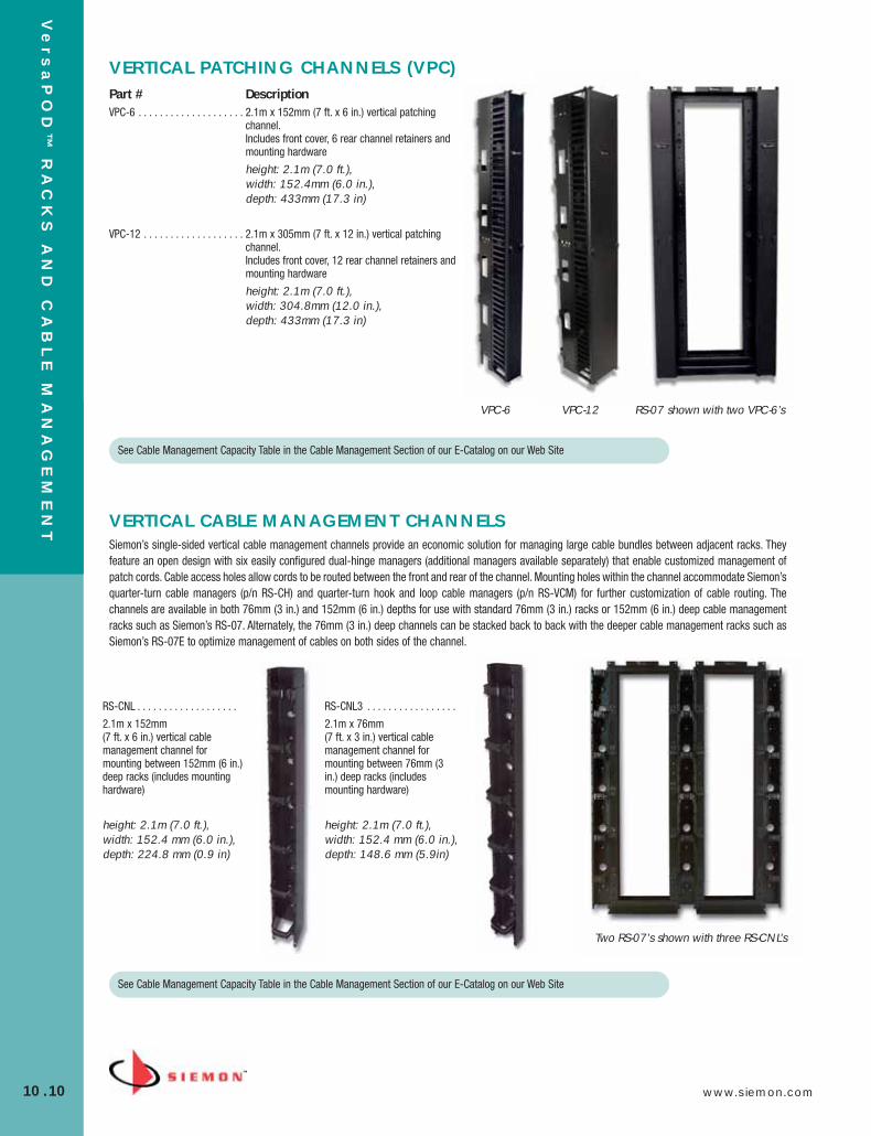
Ve
rs
aP
OD
™ R
AC
KS
AN
D C
AB
LE
MA
NA
GE
ME
NT
10.10 www.siemon.com
VERTICAL PATCHING CHANNELS (VPC)Part # DescriptionVPC-6 . . . . . . . . . . . . . . . . . . . . 2.1m x 152mm (7 ft. x 6 in.) vertical patching
channel. Includes front cover, 6 rear channel retainers andmounting hardware
height: 2.1m (7.0 ft.),width: 152.4mm (6.0 in.),depth: 433mm (17.3 in)
VPC-12 . . . . . . . . . . . . . . . . . . . 2.1m x 305mm (7 ft. x 12 in.) vertical patchingchannel. Includes front cover, 12 rear channel retainers andmounting hardware
height: 2.1m (7.0 ft.),width: 304.8mm (12.0 in.),depth: 433mm (17.3 in)
VERTICAL CABLE MANAGEMENT CHANNELSSiemon’s single-sided vertical cable management channels provide an economic solution for managing large cable bundles between adjacent racks. Theyfeature an open design with six easily configured dual-hinge managers (additional managers available separately) that enable customized management ofpatch cords. Cable access holes allow cords to be routed between the front and rear of the channel. Mounting holes within the channel accommodate Siemon’squarter-turn cable managers (p/n RS-CH) and quarter-turn hook and loop cable managers (p/n RS-VCM) for further customization of cable routing. Thechannels are available in both 76mm (3 in.) and 152mm (6 in.) depths for use with standard 76mm (3 in.) racks or 152mm (6 in.) deep cable managementracks such as Siemon’s RS-07. Alternately, the 76mm (3 in.) deep channels can be stacked back to back with the deeper cable management racks such asSiemon’s RS-07E to optimize management of cables on both sides of the channel.
RS-CNL . . . . . . . . . . . . . . . . . . .
2.1m x 152mm (7 ft. x 6 in.) vertical cablemanagement channel formounting between 152mm (6 in.)deep racks (includes mountinghardware)
height: 2.1m (7.0 ft.),width: 152.4 mm (6.0 in.),depth: 224.8 mm (0.9 in)
RS-CNL3 . . . . . . . . . . . . . . . . .
2.1m x 76mm (7 ft. x 3 in.) vertical cablemanagement channel formounting between 76mm (3in.) deep racks (includesmounting hardware)
height: 2.1m (7.0 ft.),width: 152.4 mm (6.0 in.),depth: 148.6 mm (5.9in)
Two RS-07’s shown with three RS-CNL’s
See Cable Management Capacity Table in the Cable Management Section of our E-Catalog on our Web Site
RS-07 shown with two VPC-6’sVPC-6 VPC-12
See Cable Management Capacity Table in the Cable Management Section of our E-Catalog on our Web Site
10_RCM.qxd:RCM 1/26/10 2:28 PM Page 11
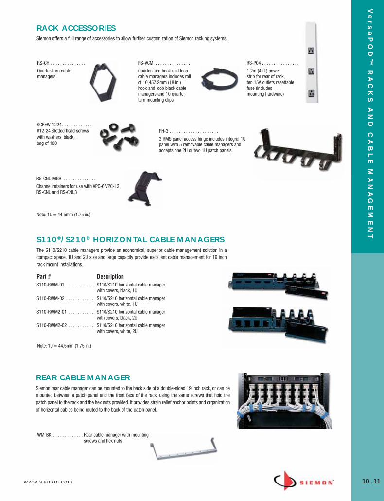
www.siemon.com
Ve
rs
aP
OD
™ R
AC
KS
AN
D C
AB
LE
MA
NA
GE
ME
NT
10.11
RS-CH . . . . . . . . . . . . . . .
Quarter-turn cablemanagers
RACK ACCESSORIESSiemon offers a full range of accessories to allow further customization of Siemon racking systems.
RS-VCM. . . . . . . . . . . . . . . .
Quarter-turn hook and loopcable managers includes rollof 10 457.2mm (18 in.)hook and loop black cablemanagers and 10 quarter-turn mounting clips
RS-P04 . . . . . . . . . . . . . . . .
1.2m (4 ft.) power strip for rear of rack, ten 15A outlets resettablefuse (includes mounting hardware)
PH-3 . . . . . . . . . . . . . . . . . . . . .
3 RMS panel access hinge includes integral 1Upanel with 5 removable cable managers andaccepts one 2U or two 1U patch panels
SCREW-1224. . . . . . . . . . . . . #12-24 Slotted head screwswith washers, black, bag of 100
RS-CNL-MGR . . . . . . . . . . . . . .
Channel retainers for use with VPC-6,VPC-12,RS-CNL and RS-CNL3
Part # DescriptionS110-RWM-01 . . . . . . . . . . . . . S110/S210 horizontal cable manager
with covers, black, 1U
S110-RWM-02 . . . . . . . . . . . . . S110/S210 horizontal cable manager with covers, white, 1U
S110-RWM2-01 . . . . . . . . . . . . S110/S210 horizontal cable manager with covers, black, 2U
S110-RWM2-02 . . . . . . . . . . . . S110/S210 horizontal cable manager with covers, white, 2U
S110®/S210® HORIZONTAL CABLE MANAGERSThe S110/S210 cable managers provide an economical, superior cable management solution in acompact space. 1U and 2U size and large capacity provide excellent cable management for 19 inchrack mount installations.
Note: 1U = 44.5mm (1.75 in.)
REAR CABLE MANAGERSiemon rear cable manager can be mounted to the back side of a double-sided 19 inch rack, or can bemounted between a patch panel and the front face of the rack, using the same screws that hold thepatch panel to the rack and the hex nuts provided. It provides strain relief anchor points and organizationof horizontal cables being routed to the back of the patch panel.
WM-BK . . . . . . . . . . . . . Rear cable manager with mountingscrews and hex nuts
Note: 1U = 44.5mm (1.75 in.)
10_RCM.qxd:RCM 1/26/10 2:28 PM Page 12

Ve
rs
aP
OD
™ R
AC
KS
AN
D C
AB
LE
MA
NA
GE
ME
NT
10.12 www.siemon.com
WM-143-5
WM-144-5
WM-145-5
WM SERIES HORIZONTAL CABLE MANAGERSThe WM series cable managers provide increased strength and do not interfere with panels mountedabove or below. They are a popular and economical solution for providing a clean and simple meansof organizing small-to-large bundles of cables and patch cords.
Part # DescriptionWM-143-5 . . . . . . . . . . . . . . . . Horizontal cable manager with five S143 hangers 1U
WM-144-5 . . . . . . . . . . . . . . . . Horizontal cable manager with five S144 hangers, 2U
WM-145-5 . . . . . . . . . . . . . . . . Horizontal cable manager with five S145 hangers, 2U
Note: 1U = 44.5mm (1.75 in.)
CABLE HANGERSThe cable hanger design features structural integrity and sleek appearance. These cable hangers are idealfor routing small to very large quantities of cables. The durable plastic design ensures reliability for anyapplication.
S143
S144
S145
S147
S146
Part # Height Width DepthS143* . . . . . . . . . . . . . . 44mm (1.73 in.) . . . . . . . . . . . . . 38mm (1.50 in.) . . . . . . . . . . . . . 89mm (3.35 in.)
S144* . . . . . . . . . . . . . . 87mm (3.43 in.) . . . . . . . . . . . . . 57mm (2.25 in.) . . . . . . . . . . . . . 74mm (2.90 in.)
S145* . . . . . . . . . . . . . . 87mm (3.43 in.) . . . . . . . . . . . . . 57mm (2.25 in.) . . . . . . . . . . . . . 125mm (4.93 in.)
S146 . . . . . . . . . . . . . . . 151mm (5.95 in.) . . . . . . . . . . . . 63mm (2.50 in.) . . . . . . . . . . . . . 130mm (5.15 in.)
S147 . . . . . . . . . . . . . . . 254mm (10.00 in.) . . . . . . . . . . . 63mm (2.50 in.) . . . . . . . . . . . . . 130mm (5.15 in.)
*Add “-A” for optional adhesive backing.
Part #SBH-2 . . . . . . . . . . . . . . 2U
Part #SBH-4 . . . . . . . . . . . . . . 4U
Part #SBH-3 . . . . . . . . . . . . . . 3U
Part #SBH-6* . . . . . . . . . . . . . 6U
STAND-OFF BRACKETS Siemon hinged stand-off brackets can be mounted to a wall with the hinge on either side forconvenient access to the back of the panel. The sides of the brackets will accept our S144 or S145cable hangers for external cable management. The brackets accept any combination of Siemonpatch panels and rack-mount cable management. Mounting hardware included.
height: See U information, width: 483mm (19 in.), depth: 152mm (6 in.)
*Add -2 for (3) independent 2U hinges (instead of a single 6U hinge).
Note: 1U = 44.5mm (1.75 in.)
10_RCM.qxd:RCM 1/26/10 2:28 PM Page 13

www.siemon.com
Ve
rs
aP
OD
™ R
AC
KS
AN
D C
AB
LE
MA
NA
GE
ME
NT
10.13
10_RCM.qxd:RCM 1/26/10 2:28 PM Page 14

PR
OD
UC
T
11.0 www.siemon.com
SECTION CONTENTSIndustrial MAX® . . . . . . . . . . . . . . . . . . . . . . . . . . . . . . . . . . . . . . . . .11.1
Industrial MAX 6/6A Outlets . . . . . . . . . . . . . . . . . . . . . . . . . . . . . . . . 11.1
Industrial MAX 5e Outlets . . . . . . . . . . . . . . . . . . . . . . . . . . . . . . . . . 11.1
Industrial MAX 5e Plugs . . . . . . . . . . . . . . . . . . . . . . . . . . . . . . . . . . . 11.1
Industrial MAX 6 Modular Patch Cords . . . . . . . . . . . . . . . . . . . . . . . . 11.2
Industrial MAX 5e Modular Patch Cords . . . . . . . . . . . . . . . . . . . . . . . 11.2
Industrial MAX Dust Caps . . . . . . . . . . . . . . . . . . . . . . . . . . . . . . . . . 11.2
Industrial MAX Surface Mount Boxes . . . . . . . . . . . . . . . . . . . . . . . . . 11.3
Industrial MAX Stainless Steel Faceplates . . . . . . . . . . . . . . . . . . . . . 11.3
Industrial LC Fiber Connectivity . . . . . . . . . . . . . . . . . . . . . . . 11.4 – 11.5
Industrial LC Fiber Plug and Outlet . . . . . . . . . . . . . . . . . . . . . . . . . . . 11.5
Field-Installable LC Fiber Connector . . . . . . . . . . . . . . . . . . . . . . . . . 11.5
Industrial LC Fiber Upgrade Kit . . . . . . . . . . . . . . . . . . . . . . . . . . . . . 11.5
11_Industrial.qxd:ZMax_Catalog 1/4/10 12:03 PM Page 1

www.siemon.com
IND
US
TR
IAL
11.1
Siemon is well-known for its industry leading high performance connectivity. The same high performancecopper and fiber products are available with our patented Industrial MAX housings. Industrial MAX outlets andmodular patch cords provide an IP66/IP67-rated seal, protecting plug and outlet contacts from dust, moisture,vibration, and common cleaning chemicals. The Industrial MAX solution is ideal for protecting valuableconnections in laboratory environments, hospitals, food processing plants and other harsh environments.
Meets Harsh Demands of the Environment
Vibration Causes Pitting In Typical Outlets
Humidity Affects TypicalOutlets
Specially designed Industrial MAX 5e and 6connectors can withstand humidity, dust andvibration.
Seen under a microscope after exposure to extremevibration, contact between a typical modular plug
and outlet can pit the contact pins, causingintermittent transmission problems.
Humidity corrodes contact pins inside typicaloutlets. Repeated exposure can eventually destroy
the contact pins, rendering the outlet unusable.The Industrial MAX outlet’s special housing
prevents this corrosion.
Standardized Interface — The Industrial MAX Connector hasbeen recognised by the Open DeviceNet Vendor Association (ODVA),TIA TR 42.9 and IEC 61076-3-106
Easy Termination — The UTP Industrial MAX outlet utilises astandard 110 tool for quick and easy punch-down termination
Universal Wiring — Each outlet is compatible with both T568Aand T568B wiring options
Ensures Proper Seal — Bayonet-style mating ensures properplug depth into the outlet and an IP66/IP67 rated seal
1
Siemon’s patented Pyramid WireEntry System on S310 blocks separates paired conductors whenlacing cables to simplify and reduceinstallation time.
3
4
2
1
2
34
Industrial MAX®
11_Industrial.qxd:ZMax_Catalog 1/4/10 12:03 PM Page 2
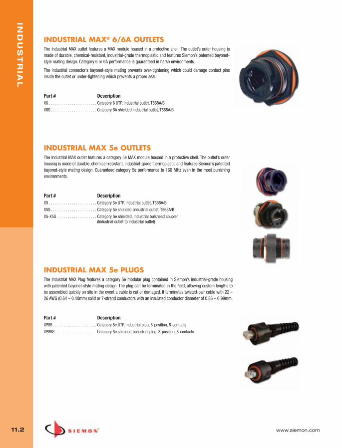
IND
US
TR
IAL
11.2 www.siemon.com
INDUSTRIAL MAX® 6/6A OUTLETSThe Industrial MAX outlet features a MAX module housed in a protective shell. The outlet’s outer housing ismade of durable, chemical-resistant, industrial-grade thermoplastic and features Siemon’s patented bayonet-style mating design. Category 6 or 6A performance is guaranteed in harsh environments.
The industrial connector’s bayonet-style mating prevents over-tightening which could damage contact pinsinside the outlet or under-tightening which prevents a proper seal.
Part # DescriptionX6 . . . . . . . . . . . . . . . . . . . . . . . Category 6 UTP, industrial outlet, T568A/B
X6S . . . . . . . . . . . . . . . . . . . . . . Category 6A shielded industrial outlet, T568A/B
INDUSTRIAL MAX 5e OUTLETSThe Industrial MAX outlet features a category 5e MAX module housed in a protective shell. The outlet’s outerhousing is made of durable, chemical-resistant, industrial-grade thermoplastic and features Siemon’s patentedbayonet-style mating design. Guaranteed category 5e performance to 160 MHz even in the most punishingenvironments.
Part # DescriptionX5 . . . . . . . . . . . . . . . . . . . . . . . Category 5e UTP, industrial outlet, T568A/B
X5S . . . . . . . . . . . . . . . . . . . . . . Category 5e shielded, industrial outlet, T568A/B
X5-X5S . . . . . . . . . . . . . . . . . . . Category 5e shielded, industrial bulkhead coupler(Industrial outlet to industrial outlet)
INDUSTRIAL MAX 5e PLUGSThe Industrial MAX Plug features a category 5e modular plug contained in Siemon’s industrial-grade housingwith patented bayonet-style mating design. The plug can be terminated in the field, allowing custom lengths tobe assembled quickly on site in the event a cable is cut or damaged. It terminates twisted-pair cable with 22 –26 AWG (0.64 – 0.40mm) solid or 7-strand conductors with an insulated conductor diameter of 0.86 – 0.99mm.
Part # DescriptionXP85 . . . . . . . . . . . . . . . . . . . . . Category 5e UTP, industrial plug, 8-position, 8-contacts
XP85S . . . . . . . . . . . . . . . . . . . . Category 5e shielded, industrial plug, 8-position, 8-contacts
11_Industrial.qxd:ZMax_Catalog 1/4/10 12:03 PM Page 3
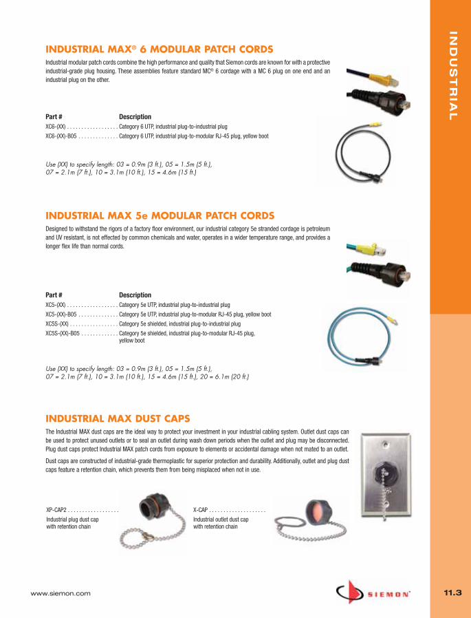
www.siemon.com
IND
US
TR
IAL
11.3
INDUSTRIAL MAX® 6 MODULAR PATCH CORDSIndustrial modular patch cords combine the high performance and quality that Siemon cords are known for with a protectiveindustrial-grade plug housing. These assemblies feature standard MC® 6 cordage with a MC 6 plug on one end and anindustrial plug on the other.
Part # DescriptionXC6-(XX) . . . . . . . . . . . . . . . . . . Category 6 UTP, industrial plug-to-industrial plug
XC6-(XX)-B05 . . . . . . . . . . . . . . Category 6 UTP, industrial plug-to-modular RJ-45 plug, yellow boot
Use (XX) to specify length: 03 = 0.9m (3 ft.), 05 = 1.5m (5 ft.), 07 = 2.1m (7 ft.), 10 = 3.1m (10 ft.), 15 = 4.6m (15 ft.)
INDUSTRIAL MAX DUST CAPSThe Industrial MAX dust caps are the ideal way to protect your investment in your industrial cabling system. Outlet dust caps canbe used to protect unused outlets or to seal an outlet during wash down periods when the outlet and plug may be disconnected.Plug dust caps protect Industrial MAX patch cords from exposure to elements or accidental damage when not mated to an outlet.
Dust caps are constructed of industrial-grade thermoplastic for superior protection and durability. Additionally, outlet and plug dustcaps feature a retention chain, which prevents them from being misplaced when not in use.
X-CAP . . . . . . . . . . . . . . . . . . . .
Industrial outlet dust cap with retention chain
XP-CAP2 . . . . . . . . . . . . . . . . . .
Industrial plug dust cap with retention chain
INDUSTRIAL MAX 5e MODULAR PATCH CORDSDesigned to withstand the rigors of a factory floor environment, our industrial category 5e stranded cordage is petroleumand UV resistant, is not effected by common chemicals and water, operates in a wider temperature range, and provides alonger flex life than normal cords.
Part # DescriptionXC5-(XX) . . . . . . . . . . . . . . . . . . Category 5e UTP, industrial plug-to-industrial plug
XC5-(XX)-B05 . . . . . . . . . . . . . . Category 5e UTP, industrial plug-to-modular RJ-45 plug, yellow boot
XC5S-(XX) . . . . . . . . . . . . . . . . . Category 5e shielded, industrial plug-to-industrial plug
XC5S-(XX)-B05 . . . . . . . . . . . . . Category 5e shielded, industrial plug-to-modular RJ-45 plug, yellow boot
Use (XX) to specify length: 03 = 0.9m (3 ft.), 05 = 1.5m (5 ft.), 07 = 2.1m (7 ft.), 10 = 3.1m (10 ft.), 15 = 4.6m (15 ft.), 20 = 6.1m (20 ft.)
11_Industrial.qxd:ZMax_Catalog 1/4/10 12:03 PM Page 4
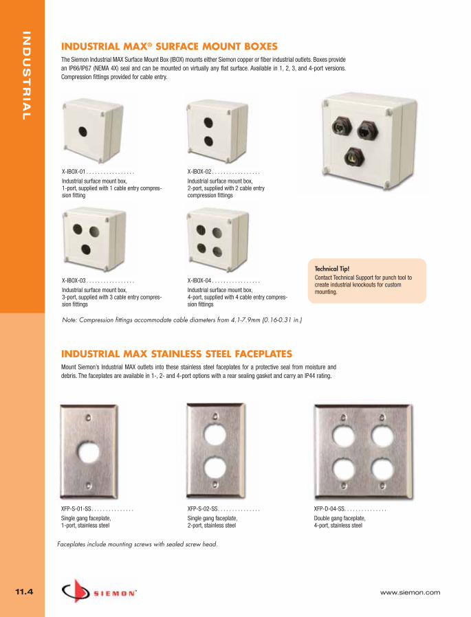
IND
US
TR
IAL
11.4 www.siemon.com
INDUSTRIAL MAX® SURFACE MOUNT BOXESThe Siemon Industrial MAX Surface Mount Box (IBOX) mounts either Siemon copper or fiber industrial outlets. Boxes providean IP66/IP67 (NEMA 4X) seal and can be mounted on virtually any flat surface. Available in 1, 2, 3, and 4-port versions.Compression fittings provided for cable entry.
INDUSTRIAL MAX STAINLESS STEEL FACEPLATESMount Siemon’s Industrial MAX outlets into these stainless steel faceplates for a protective seal from moisture anddebris. The faceplates are available in 1-, 2- and 4-port options with a rear sealing gasket and carry an IP44 rating.
XFP-S-01-SS. . . . . . . . . . . . . . .
Single gang faceplate, 1-port, stainless steel
XFP-S-02-SS. . . . . . . . . . . . . . .
Single gang faceplate, 2-port, stainless steel
XFP-D-04-SS. . . . . . . . . . . . . . .
Double gang faceplate, 4-port, stainless steel
Faceplates include mounting screws with sealed screw head.
X-IBOX-03 . . . . . . . . . . . . . . . . .
Industrial surface mount box, 3-port, supplied with 3 cable entry compres-sion fittings
X-IBOX-04 . . . . . . . . . . . . . . . . .
Industrial surface mount box, 4-port, supplied with 4 cable entry compres-sion fittings
X-IBOX-01 . . . . . . . . . . . . . . . . .
Industrial surface mount box, 1-port, supplied with 1 cable entry compres-sion fitting
X-IBOX-02 . . . . . . . . . . . . . . . . .
Industrial surface mount box, 2-port, supplied with 2 cable entry compression fittings
Technical Tip!Contact Technical Support for punch tool tocreate industrial knockouts for custommounting.
Note: Compression fittings accommodate cable diameters from 4.1-7.9mm (0.16-0.31 in.)
11_Industrial.qxd:ZMax_Catalog 1/4/10 12:03 PM Page 5

www.siemon.com
IND
US
TR
IAL
11.5
Precision Performance Robust and ReliableMeets Harsh Demands
of the Environment
R&D labs develop, design and implement rigoroustesting programs using sophisticatedinstrumentation. The Industrial LC provides reliabilitywith leading edge technology for applications wherehighly accurate performance is critical.
Industrial Fiber connections help to streamlineoperations, improve product availability, andreduce costs in manufacturing environments.
The Industrial LC connector is ideal in areas wherechemicals, corrosive gases and liquids are
commonplace.
Robust Design — Protects fiber connections in virtually any harshenvironment
High Performance — Meets TIA-568-C.3 and, ISO/IEC 11801 Ed2.0 specifications for multimode components
Proper Seal — Bayonet-style mating ensures proper fiberalignment and an IP66/IP67 rated seal
Specialized Bend Relief — Compression fitting provides asuperior rear seal and ensures fiber meet minimum bend radiusrequirements
Field-Termination — Plug includes two industrial qualifiedmultimode LC connectors that accepts 2 strand, round, breakoutstyle fiber optic cable
1
2
3
4
Rear of adapter accepts standard LC multimode
connectors.
Another first from Siemon — the Industrial LC Fiber system. The Siemon Industrial LC Fiber solution providesa robust fiber connection with an IP66/IP67-rated seal and is ideal for protecting valuable connections inlaboratory environments, hospitals, food processing plants and other harsh environments.
The Siemon Industrial Fiber solution is ideal for installations requiring extended distances (up to 300 meters),in close proximity to heavy sources of EMI, or where fiber active equipment is used.
5
1 2
3
4
5
Industrial LC Fiber Connectivity
11_Industrial.qxd:ZMax_Catalog 1/4/10 12:04 PM Page 6
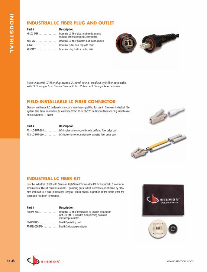
IND
US
TR
IAL
11.6 www.siemon.com
FIELD-INSTALLABLE LC FIBER CONNECTORSiemon multimode LC buffered connectors have been qualified for use in Siemon’s industrial fibersystem. Use these connectors to terminate 62.5/125 or 50/125 multimode fiber and plug into the rearof the Industrial LC outlet.
Part # DescriptionFC1-LC-MM-B80. . . . . . . . . . . . LC simplex connector, multimode, buffered fiber beige boot
FC2-LC-MM-J80 . . . . . . . . . . . . LC duplex connector, multimode, jacketed fiber beige boot
INDUSTRIAL LC FIBER KITUse the Industrial LC Kit with Siemon’s LightSpeed Termination Kit for Industrial LC connectorterminations. The kit contains a dual LC polishing puck, which decreases polish time by 50%.Also included is a dual microscope adapter, which allows inspection of the fibers after theconnector has been terminated.
Part # DescriptionFTERM-XLC . . . . . . . . . . . . . . . . Industrial LC fiber termination kit used in conjunction
with FTERM-L2 includes dual polishing puck and microscope adapter
FT-LC2PUCK . . . . . . . . . . . . . . . Dual LC polishing puck
FT-MSLC2HEAD. . . . . . . . . . . . . Dual LC microscope adapter
INDUSTRIAL LC FIBER PLUG AND OUTLETPart # DescriptionXPLC2-MM . . . . . . . . . . . . . . . . Industrial LC fiber plug, multimode, duplex.
Includes two multimode LC connectors
XLC-MM . . . . . . . . . . . . . . . . . . Industrial LC fiber adapter, multimode, duplex
X-CAP . . . . . . . . . . . . . . . . . . . . Industrial outlet dust cap with chain
XP-CAP2 . . . . . . . . . . . . . . . . . . Industrial plug dust cap with chain
Note: Industrial LC fiber plug accepts 2 strand, round, breakout style fiber optic cable with O.D. ranges from 5mm – 8mm with two 2.4mm – 3.0mm jacketed subunits.
11_Industrial.qxd:ZMax_Catalog 1/4/10 12:04 PM Page 7
www.siemon.com
IND
US
TR
IAL
11.7
11_Industrial.qxd:ZMax_Catalog 1/4/10 12:04 PM Page 8

TO
OL
S A
ND
TE
ST
ER
S
12.0 www.siemon.com
SECTION CONTENTS
STM-8 . . . . . . . . . . . . . . . . . . . . . . . . . . . . . . . . . . . . . . . . . . 12.1 – 12.2
STM-8 Accessories . . . . . . . . . . . . . . . . . . . . . . . . . . . . . . . . . . . . . . 12.2
Z-TOOL™ . . . . . . . . . . . . . . . . . . . . . . . . . . . . . . . . . . . . . . . . . . . . . .12.3
TESTAR® . . . . . . . . . . . . . . . . . . . . . . . . . . . . . . . . . . . . . . . . . . . . . .12.4
S110® Test Adapters . . . . . . . . . . . . . . . . . . . . . . . . . . . . . . . . . . . . . 12.4
S110/S210® Multi-Pair Termination Tools . . . . . . . . . . . . . . . . . . . . . 12.5
S814 Impact Tool . . . . . . . . . . . . . . . . . . . . . . . . . . . . . . . . . . . . . . . . 12.5
Palm Guard . . . . . . . . . . . . . . . . . . . . . . . . . . . . . . . . . . . . . . . . . . . . 12.6
CI-KIT . . . . . . . . . . . . . . . . . . . . . . . . . . . . . . . . . . . . . . . . . . . . . . . . 12.6
CI-KIT2 . . . . . . . . . . . . . . . . . . . . . . . . . . . . . . . . . . . . . . . . . . . . . . . 12.6
AllPrep™ Cable Preparation Tool . . . . . . . . . . . . . . . . . . . . . . . . . . . . 12.6
TERA® Cable Preparation Tool . . . . . . . . . . . . . . . . . . . . . . . . . . . . . . 12.6
CPT-WEB . . . . . . . . . . . . . . . . . . . . . . . . . . . . . . . . . . . . . . . . . . . . . . 12.6
012_Tools.qxd:ZMax_Catalog 1/4/10 12:07 PM Page 1

www.siemon.com
TO
OL
S A
ND
TE
ST
ER
S
12.1
The STM-8 is an economical and versatile hand-held tester designed for the testing of UTP and shielded cablefor opens, shorts, reversals, miswires, split pairs and cable length. Its rugged, state-of-the-art construction,easy-to-read LCD display and multiple remotes allow one person to quickly test and identify up to fourdifferent cable runs from one location.
Tests All WiringConfigurations
DeterminesUnknown Wiring
DeterminesCable Length
Tests T568A, T568B, USOC, 10BASE-T, Token Ring,and TP-PMD wiring configurations.
In FIND mode, the STM-8 will detect and identify which wiring scheme is present in the
cable being tested.
In the LENGTH mode, the STM-8 will determine thedistance measurements on any given cable up to900m (2950 ft.). This feature may be used with
all four identifiable remotes.
Extended Battery Life — A low battery status indication isprovided, as well as automatic shut-off
Long Length Testing — Test cable runs up to 900m (2950 ft.)
Easy Reference — Indications for 6- and 8-position jacks
Line Voltage Indicator — The presence of line voltage isindicated on the display to help prevent accidental damage to theunit
Multi-Location Testing — Additional remotes can be purchasedseparately
Universal Compatibility — The UTP modular cords are equipped with patented “universal” plugs, that fit into any standard 6- or 8-position modular jack
1
2
3
4
5
6
1 2
3
4
5
6
STM-8
012_Tools.qxd:ZMax_Catalog 1/4/10 12:07 PM Page 2
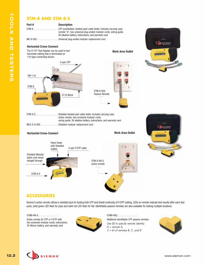
TO
OL
S A
ND
TE
ST
ER
S
12.2 www.siemon.com
STM-8 AND STM-8-SPart # DescriptionSTM-8 . . . . . . . . . . . . . . . . . . . . UTP (unshielded, twisted-pair) cable tester. Includes carrying case,
remote “A”, two universal plug-ended modular cords, wiring guide, 9V alkaline battery, instructions, and warranty card
MC-8-005 . . . . . . . . . . . . . . . . . Universal plug-ended modular replacement cord
STM-8-S . . . . . . . . . . . . . . . . . . Shielded twisted-pair cable tester. Includes carrying case, active remote, two screened modular cords, wiring guide, 9V alkaline battery, instructions, and warranty card
MC5-S-8-005 . . . . . . . . . . . . . . Shielded modular replacement cord
STM8-RA-S . . . . . . . . . . . . . . . .
Active remote for UTP or F/UTP with two screened modular cords, instructions, 3V lithium battery, and warranty card
STM8-R(X). . . . . . . . . . . . . . . . .
Additional identifiable UTP passive remotes
Use (X) to specify remote identity: A = remote A, 3 = kit of remotes B, C, and D
ACCESSORIESSiemon’s active remote utilizes a shielded jack for testing both UTP and shield continuity of F/UTP cabling. LEDs on remote indicate test results after each testcycle; solid green LED flash for pass and solid red LED flash for fail. Identifiable passive remotes are also available for testing multiple locations.
Work Area Outlet
TAP-110
S110 Block
STM-8
4-pair UTP
STM-8-R(X)Passive Remote
Horizontal Cross-ConnectThe S110® Test Adapter can be used to test horizontal cabling that is terminated on 110-type connecting blocks
Work Area Outlet
4-pair F/UTP cable
Horizontal Cross-Connect
STM-8-RA-Sactive remote
Shielded Modularpatch cord wiredstraight through
STM-8-S
Patch Panel with Shieldedoutlets
012_Tools.qxd:ZMax_Catalog 1/4/10 12:08 PM Page 3

www.siemon.com
TO
OL
S A
ND
TE
ST
ER
S
12.3
1
5
2
3
4
6
Z-TOOLTM and AccessoriesThe Z-TOOL is an integral part of the exclusive Z-MAX™ termination process and is used with both UTPand shielded Z-MAX modules. This easy-to-use and ergonomic designed tool is used both to secure thecable retention/grounding clip and to fully enage the termination module into the back of the outlet.
Ergonomic — Minimal hand strain, limited pressure andzero-impact for comfortable repeatability
Alignment Aids — Keyed guide ensures correct outletinsertion during termination
One-Handed Activation — Allows final Z-MAX terminationstep to be accomplished with one hand for operation space-restricted areas
Retention Clip Locking — Additional function closes andlocks hinged cable retention/grounding clip
Slim Profile — To fit in a pocket or toolbox
Attachment Point — For key ring or lanyard and rack-mount capability
Part # DescriptionZ-TOOL . . . . . . . . . . . . . . . . . . . Z-MAX Termination Tool
CPT-RGTP . . . . . . . . . . . . . . . . . AllPrep™ cable preparation tool for twisted pair cables
CPT-DIE-TP . . . . . . . . . . . . . . . . Replacement All-Prep Category 6 die
Z-MAX ICON CARDS
The innovative Z-MAX icon card contains four high-visibility print, 2-sided icons to provide a variety
of options for outlet identification and supplemental color coding. The icons are secured in a
durable frame to eliminate loose and easily lost parts.
All Cards Include:
- Red and blue icons with voice and data symbols
- Supplemental/color-matched icon with voice, data, and blank designation
- 1 white blank icon for field designation
- Fully recyclable material
Z-ICON-(XX)B. . . . . . . . . . . . . . . Z-MAX Icon Card, bag of 100
Primary Color01 = Black02 = White
03 = Red04 = Gray
05 = Yellow06 = Blue
07 = Green09 = Orange
20 = Ivory80 = Light Ivory
1
5
6
4
3
2
Front Rear
012_Tools.qxd:ZMax_Catalog 1/4/10 12:08 PM Page 4

TO
OL
S A
ND
TE
ST
ER
S
12.4 www.siemon.com
S110® TEST ADAPTERSSiemon’s 1-, 2-, 3-, and 4-pair S110 test adapters provide a convenient way to test 110-typeconnecting blocks. These adapters plug directly onto any 110-type connecting block and provide amodular jack for connection to test equipment or patch cords. It is the only 110 style test adapter thatcan be attached to both terminated and unterminated 110-type connecting blocks. The 2-, 3-, and 4-pair adapters are end-stackable, and are polarized to prevent incorrect insertion.
The 4-pair test adapters have an area for a colored icon (a blue and red icon are included) for additionalidentification. The 4-pair adapter is available in T568A and T568B wiring configurations and is category5e compatible for high-performance link testing.
Part # DescriptionTAP-110-T4. . . . . . . . . . . . . . . . Category 5e compatible, 4-pair, 8-position,
test adapter, T568A
TAP-110-A4. . . . . . . . . . . . . . . . Category 5e compatible, 4-pair, 8-position, test adapter, T568B
4-pair
1-pair 2-pair 3-pair 4-pair
TESTAR®
The TESTAR creates easy test access to 66 quick clips. It plugs directly onto the S66 block, establishinga positive connection and providing a 4-pair modular jack for plugging in test equipment. The body ismolded in blue plastic and has molded-in finger grips for easy handling.
Part # DescriptionTESTAR-8T-C5. . . . . . . . . . . . . . Category 5e compatible, 4-pair, 8-position,
TESTAR, T568A
TESTAR-8A-C5 . . . . . . . . . . . . . Category 5e compatible, 4-pair, 8-position, TESTAR, T568B
OTHER TESTARSThe positive connection made by the TESTAR eliminates possible problems associated with handlingalligator clips or test probes such as accidental shorting across terminals or intermittent testconnections. Test equipment is inserted into the TESTAR through a 1-, 2-, 3-, or 4-pair modular jack.To utilize equipment requiring alligator clips, our MODAPT® adapter can be plugged into the TESTAR.
Part # DescriptionTESTAR-2 . . . . . . . . . . . . . . . . . 1-pair, 6-position, TESTAR, USOC
TESTAR-4 . . . . . . . . . . . . . . . . . 2-pair, 6-position, TESTAR, USOC
TESTAR-6 . . . . . . . . . . . . . . . . . 3-pair, 6-position, TESTAR, USOC
TESTAR-8R1 . . . . . . . . . . . . . . . 4-pair, 8-position, TESTAR, USOC
TESTAR-8 . . . . . . . . . . . . . . . . . 4-pair, 8-position, TESTAR, T568B
TESTAR-8T . . . . . . . . . . . . . . . . 4-pair, 8-position, TESTAR, T568A
Technical Tip!The adapters utilize a unique, spring-loaded contact design to ensure a reliable connection without disturbing existing cross-connect terminations. This also extends the life-cycle of the test adapter.
012_Tools.qxd:ZMax_Catalog 1/4/10 12:08 PM Page 5

www.siemon.com
TO
OL
S A
ND
TE
ST
ER
S
12.5
S110®/S210® MULTI-PAIR TERMINATION TOOLS
S814 IMPACT TOOLThe S814 impact tool terminates wires on 66 and 110 clips. The tool is spring-loaded and fully adjustable; ahelpful feature when working with wires of varying thicknesses. The bayonet-style mount allows the blades tobe changed quickly and easily, and a compartment in the handle stores an extra blade.
Part # DescriptionS814 . . . . . . . . . . . . . . . Tool body only
S814-66 . . . . . . . . . . . . Tool body with 66 termination blade
S814-110 . . . . . . . . . . . Tool body with 110 termination blade
S81401-66 . . . . . . . . . . 66 termination blade
S81401-110-88. . . . . . . 110 termination blade
Technical Tip!Termination blades for Siemon punch down tools are reversible — one end terminates and cuts off the excess wire, the other end terminates without cutting.
S788J4-210 . . . . . . . . . . . . . . . . . . . . . . . . 4-pair S210 termination tool
S788J4B-210 . . . . . . . . . . . . . . . . . . . . . . . 4-pair S210 replacement cutting blade andinsertion assembly
S788J4H-210 . . . . . . . . . . . . . . . . . . . . . . . 4-pair S210 replacement head for impacttool, including housing, cutting blade andinsertion assembly
S788J4 . . . . . . . . . . . . . . . . . . . . . . . . . . . . 4-pair S110 termination tool
S788J4B . . . . . . . . . . . . . . . . . . . . . . . . . . . 4-pair S110 replacement cutting blade andinsertion assembly
S788J4H . . . . . . . . . . . . . . . . . . . . . . . . . . . 4-pair S110 replacement head for impacttool, including housing, cutting blade andinsertion assembly
S788J5 . . . . . . . . . . . . . . . . . . . . . . . . . . . . 5-pair S110 termination tool
S788J5B . . . . . . . . . . . . . . . . . . . . . . . . . . . 5-pair S110 replacement cutting blade andinsertion assembly
S788J5H . . . . . . . . . . . . . . . . . . . . . . . . . . . 5-pair S110 replacement head for impacttool, including housing, cutting blade andinsertion assembly
012_Tools.qxd:ZMax_Catalog 1/4/10 12:08 PM Page 6

TO
OL
S A
ND
TE
ST
ER
S
12.6 www.siemon.com
CI-KITThe CI-KIT provides all the tools that a telecommunications technician needs for day-to-day activities. Included in the kit is an S814 impact tool with 66 and 110 termination blades, a probe pic, electrician’sscissors, mini flathead screwdriver, and a CPT-WEB cable preparation tool. These tools are stored in a handy,lightweight clip-on pouch which allows the installer to cut, strip, and terminate cabling without having to carry separatetools or larger tool kits.
Part # DescriptionCI-KIT . . . . . . . . . . . . . . . . . . . . Clip-on tool kit with S814 impact tool (with 66 and 110
termination blades), probe pic, electrician’s scissors, mini flathead screwdriver, and CPT-WEB tool
CI-POUCH . . . . . . . . . . . . . . . . . Clip-on CI-KIT tool pouch only
PALM GUARDThe Siemon palm guard has been ergonomically designed to provide a safe and convenient means of terminating ourUTP and screened flat or angled CT couplers and MAX® modules. The palm guard absorbs the impact of terminationwhile securing the connector to prevent movement. Includes an adjustable elastic strap and a removable insert, whichcan be used to hold MAX modules while terminating on flat surfaces.
Part # DescriptionPG . . . . . . . . . . . . . . . . . . . . . . . Palm guard with MAX insert
“D-Ring”
CI-KIT2Siemon’s CI-KIT2 includes all the components of the standard CI-KIT, with the addition of our popular AllPrep™ cablepreparation tool (see page 13.7) in place of the CPT-WEB tool. Also, a “D-Ring” has been added to carry additionaltools. These tools are stored in a handy, lightweight, clip-on pouch which allows the installer to cut, strip and terminatecabling without having to carry separate tools or larger tool kits.
Part # DescriptionCI-KIT2 . . . . . . . . . . . . . . . . . . . Clip-on tool kit with S814 impact tool, (with 66 and 110
termination blades), probe pic, electrician’s scissors, mini flathead screwdriver, and AllPrep cable preparation tool
CI-POUCH2 . . . . . . . . . . . . . . . . Clip-on CI-KIT2 tool pouch only
012_Tools.qxd:ZMax_Catalog 1/4/10 12:08 PM Page 7

www.siemon.com
TO
OL
S A
ND
TE
ST
ER
S
12.7
ALLPREP™ CABLE PREPARATION TOOLThe AllPrep cable preparation tool provides a robust and reliable method of preparing bothcoaxial and twisted-pair cable for termination. The tool features two color-coded dies thatare interchangeable for each media type. The coaxial die strips RG59 and RG6 coaxial cableand the twisted-pair die strips a wide variety of UTP, screened and fiber cables.
Part # DescriptionCPT-RGTP . . . . . . . . . . . . . . . . . AllPrep cable preparation tool
for coax/twisted pair cables
CPT-DIE-RG . . . . . . . . . . . . . . . . Replacement coax die (black)
CPT-DIE-TP . . . . . . . . . . . . . . . . Replacement twisted-pair die (yellow)
TERA® CABLE PREPARATION TOOLThe TERA cable preparation tool uses a patent pending process to significantly reduce the time required to prepare fully shielded (S/FTP) cable. The toolincludes an insert die with a blade, which is specifically designed to accurately strip thejacket and foil from 4-pair fully shielded cable without damaging the conductors. A templateis also included to pre-align cable pairs and ensure proper pair positioning duringtermination.
Part # DescriptionCPT-T . . . . . . . . . . . . . . . . . . . . TERA preparation tool. Includes CPT-DIE-T4 and
TERA cable preparation template
CPT-DIE-T4 . . . . . . . . . . . . . . . . Replacement TERA cable die (red)
CPT-DIE-TMPL. . . . . . . . . . . . . . Replacement TERA wiring guide
CPTThe CPT provides a simple and effective method to remove the outer cable jacket from 2-,3-, or 4-pair cables without damaging the inner conductor insulation. The CPT isrecommended for use with any round cable with an exterior diameter from 2.54 – 6.35mm(0.100 – 0.250 in.) and an outer jacket thickness from 0.380 – 0.635mm (0.015 – 0.025in.).
Part # DescriptionCPT . . . . . . . . . . . . . . . . . . . . . . Cable preparation tool
CPT-WEBThe CPT-WEB is designed to easily strip the outer cable jacket, flatten and separate thewebbed conductors of Siemon’s category 5e cross-connect jumper wire and other UTP cablewith webbed conductor pairs.
Part # DescriptionCPT-WEB. . . . . . . . . . . . . . . . . . Webbed cable preparation tool
CPT-DIE-RG
CPT-DIE-TP
CPT-DIE-T4 CPT-DIE-TMPL
012_Tools.qxd:ZMax_Catalog 1/4/10 12:08 PM Page 8
GL
OS
SA
RY
13.0 www.siemon.com
Alien Crosstalk: Noise or interference caused by electromagnetic couplingfrom one cable to another cable, expressed in decibels.
Attenuation: See Insertion Loss.
Attenuation to Crosstalk Ratio (ACR): The difference between insertionloss and crosstalk measured in decibels.
Attenuation to Crosstalk Ratio, Far-end (ACR-F): Crosstalk measured atthe opposite end from which the disturbing signal is transmitted, normalizedby the insertion loss of the cable or cabling.
Backbone Cabling: Cable and connecting hardware that comprise the mainand intermediate cross-connects, as well as cable runs that extend betweentelecommunications rooms, equipment rooms and entrance facilities.
Balance An indication of signal voltage equality and phase polarity on aconductor pair. Perfect balance occurs when the signals across a twisted-pair are equal in magnitude and opposite in phase with respect to ground.
Balanced Signal Transmission: Two voltages, equal and opposite in phasewith respect to each other, across the conductors of a twisted-pair (com-monly referred to as tip and ring).
Balun: An impedance matching transformer used to convert unbalancedsignals to balanced signals and vice versa.
Bandwidth: A range of frequencies, usually the difference between theupper and lower limits of the range, typically expressed in megahertz (MHz).It may also be used to describe the information-carrying capacity of amedium. Optical fiber bandwidth is specified in megahertz kilometers (MHz-km).
Bonding: The permanent joining of metallic parts to form an electricallyconductive path that will assure electrical continuity and the capacity to con-duct safely any current likely to be imposed on it.
Bridged Tap: The multiple appearances of the same cable pair or fiber atseveral distribution points. Also known as parallel connections.
Bridging: A means of providing through connections between conductors orpairs that are terminated on connecting blocks. These through connectionsare commonly provided by means of individual metallic “bridging” clips ormultiple “bridging” clips that are housed in a plastic insulator.
Building Distributor (BD): The international term for intermediate cross-connect. A distributor in which the building backbone cable(s) terminates andat which connections to the campus backbone cable(s) may be made.
Bundled Cable: An assembly of two or more cables continuously bound to-gether to form a single unit prior to installation (sometimes referred to asloomed, speed-wrap or whip cable constructions).
Cabling: A combination of cables, wire, cords and connecting hardware usedin the telecommunications infrastructure.
Campus Backbone: Cabling between buildings that share telecommunica-tions facilities.
Campus Distributor (CD): The international term for main cross-connect.The distributor from which the campus backbone cable emanates.
Category:
1. ANSI/TIA/568-C series of documents, the North American standardsfor cabling describes mechanical properties and transmission char-acteristics of balanced cabling components and assigns a uniquenumber classification (category 3, category 5e, category 6 and category 6A).
2. ISO/IEC 11801 2nd edition, the international standard for cablingand local standardization documents define cabling component cat-egories based on transmission performance parameters such as at-tenuation and NEXT loss, over a specified frequency range.Component categories category 5, category 6, category 6Acategory 7 and category 7A.
Channel: The end-to-end transmission path connecting any two points atwhich application specific equipment is connected. Equipment and workarea cables are included in the channel.
Classification: Application classes for cabling have been identified for thepurpose of the ISO/IEC 11801 standard;
– Class A: cabling is characterized up to 100 kHz– Class B: cabling is characterized up to 1 MHz– Class C: cabling is characterized up to 16 MHz– Class D: cabling is characterized up to 100 MHz– Class E: cabling is characterized up to 250 MHz– Class EA: cabling is characterized up to 500 MHz – Class F: cabling is characterized up to 600 MHz – Class FA: cabling is characterized up to 1000 MHz– Optical Class: optical fiber links are characterized from 10 MHz and
above.
Collapsed Backbone: A centralized network contained in one device. The network is said to be collapsed and made to fit into a box. Individualnetworks are connected to this central device and can then communicatewith one another.
Common Mode Transmission: A transmission scheme where voltages ap-pear equal in magnitude and phase across a conductor pair with respect toground. May also be referred to as longitudinal mode.
Consolidation Point (CP): A location for interconnection between horizontalcables that extend from building pathways and horizontal cables that extendinto work area pathways.
Cross-connect: A facility enabling the termination of cables as well as theirinterconnection or cross-connection with other cabling or equipment. Alsoknown as a distributor.
Cross-connection: A connection scheme between cabling runs, subsystemsand equipment using patch cords or jumpers that attach to connecting hard-ware on each end.
Crosstalk: Noise or interference caused by electromagnetic coupling fromone signal path to another. Crosstalk performance is generally expressed indecibels.
Decibel (dB): A standard unit for expressing transmission gain or loss as derived from a ratio of signal voltages or power.
Delay Skew: The difference in propagation delay between the fastest andslowest pair in a cable or cabling system.
Demarcation Point (DP): A point at which two services may interface andidentify the division of responsibility.
Differential Mode Transmission: A transmission scheme where voltagesappear equal in magnitude and opposite in phase across a twisted-pair withrespect to ground. May also be referred to as balanced mode.
Distributor: The term used for the functions of a collection of components (e.g. patch panels, patch-cords) used to interconnect cables.
Electromagnetic Compatibility (EMC): The ability of a system to minimizeradiated emissions and maximize immunity from external noise sources.
Electromagnetic Interference (EMI): The interference in signal transmis-sion or reception caused by the radiation of electrical and magnetic fields.
Entrance Facility (EF): An entrance to a building for both public and privatenetwork service cables (including antennae), including the entrance point atthe building wall and continuing to the entrance room or space. Entrance fa-cilities are often used to house electrical protection equipment and connect-ing hardware for the transition between outdoor and indoor cable.
013_Glossary.qxd:ZMax_Catalog 1/4/10 12:11 PM Page 1
www.siemon.com
GL
OS
SA
RY
13.1
Entrance Facility, Telecommunications: An entrance to a building for bothpublic and private network service cables (including antennae) beginning withthe entrance point at the building wall and continuing to the entrance room orspace.
Entrance Point, Telecommunications: The point of emergence of telecom-munications conductors through an exterior wall, a concrete floor slab, orfrom a rigid metal conduit or intermediate metal conduit.
Equipment Cable: A cable or cable assembly used to connect telecommuni-cations equipment to horizontal or backbone cabling.
Equipment Room (ER): A centralized space for telecommunications equip-ment that serves the occupants of the building or multiple buildings in a cam-pus environment. An equipment room is considered distinct from atelecommunications room because it is considered to be a building or cam-pus serving (as opposed to floor serving) facility and because of the nature orcomplexity of the equipment that it contains.
Equipment Room, Telecommunications: A centralized space for telecom-munications equipment that serves the occupants of the building. An equip-ment room is considered distinct from the telecommunications room becauseof the nature and complexity of the equipment it houses.
Far-end Crosstalk (FEXT): Crosstalk measured at the opposite end fromwhich the disturbing signal is transmitted.
Fiber Optic Transmission: A communications scheme whereby electricaldata is converted to light energy and transmitted through optical fibers.
Floor Distributor (FD): The international term for horizontal cross-connect.The distributor used to connect between the horizontal cable and other cabling subsystems or equipment.
Fully Shielded twisted-pair (S/FTP): A balanced twisted-pair cable contain-ing balanced twisted-pair conductors that are individually foil shielded, surrounded by an overall metallic braid, and bound in a single cable sheath.
Ground: A conducting connection, whether intentional or accidental, betweenan electrical circuit (telecommunications) or equipment and earth, or to someconducting body that serves in place of the earth.
Hertz (Hz): A measure of frequency as defined in units of cycles per second.
Horizontal Cabling: The cabling between and including the telecommunica-tions outlet and the horizontal cross-connect.
Horizontal Cross-connect (HC): A cross-connect of horizontal cabling toother cabling, e.g., horizontal, backbone, or equipment.
Hybrid Cable: An assembly of two or more cables, of the same or differenttypes or categories, covered by one overall sheath.
Insertion loss1. The loss resulting from the insertion of a device in a transmission
line, expressed as the reciprocal of the ratio of the signal power delivered to that part of the line following the device to the signalpower delivered to that same part before insertion.
2. In an optical fiber system, the loss of optical power caused by insert-ing a component, such as a connector, coupler or splice, into a previously continuous optical path.
Insulation Displacement Connection (IDC): A wire connection device thatpenetrates the insulation of a copper wire when it is being inserted (punched-down) into a metal contact, allowing the electrical connection to be made.
Interbuilding Backbone: Telecommunications cable(s) that are part of thecampus subsystem that connect one building to another.
Interconnection: A connection scheme that provides direct access to the cabling infrastructure and the ability to make cabling system changes usingequipment cords.
Intermediate Cross-Connect (IC): The connection point between a back-bone cable that extends from the main cross-connect (first-level backbone)and the backbone cable from the horizontal cross-connect (second-levelbackbone).
Intrabuilding Backbone: Telecommunications cable(s) that are part of thebuilding subsystem that connect one equipment room to another.
Jumper Wire: An assembly of twisted-pairs without connectors on either endused to join telecommunications links at a cross-connect.
Laser Optimized: A multimode optical fiber with a refractive index profileoptimized for use with laser light sources.
Link: An end-to-end transmission path provided by the cabling infrastruc-ture. Cabling links include all cables and connecting hardware that comprisethe horizontal or backbone subsystems. Equipment and work area cables arenot included as part of a link.
Local Area Network (LAN): A geographically limited data communicationssystem for a specific user group consisting of a group of interconnected com-puters, sharing applications, data and peripheral devices such as printers andCD-ROM drives intended for the local transport of data, video, and voice.
Longitudinal Conversion Loss (LCL): A measure (in dB) of the differentialvoltage induced on a conductor pair as a result of subjecting that pair to lon-gitudinal voltage. LCL is considered to be a measure of circuit balance.
Main Cross-connect (MC): A cross-connect for first level backbone cables,entrance cables, and equipment cables.
Modular Jack: A telecommunications outlet/connector for wire or cords asdefined in the FCC Part 68 Subpart F. Modular jacks can have 4, 6 or 8 con-tact positions, but not all the positions need be equipped with contacts.
Modular Plug: A telecommunications connector for wire or cords as definedin the FCC Part 68 Subpart F. Modular plugs can have 4, 6 or 8 contact posi-tions, but not all the positions need be equipped with contacts.
Multimedia:1. An application that communicates to more than one of the human
sensory receptors.
2. Applications that communicate information by more than one means or cabling media.
Multimode Optical Fiber: An optical fiber that will allow multiple modes oflight to propagate. The fiber may be either a graded-index or step-index fiber.Multimode optical fibers have a much larger core than singlemode fibers. Seealso Optical Fiber Cable.
Multi-user Telecommunications Outlet Assembly (MuTOA): A grouping inone location of several telecommunications/outlet connectors.
Nanosecond (ns): One billionth of a second (10-9 seconds).
Near-end Crosstalk (NEXT Loss): The undesired coupling of a signal fromone pair of wires to another. Signal distortion as a result of signal couplingfrom one pair to another at various frequencies.
Network Demarcation Point: The point of interconnection between the localexchange carrier’s telecommunication facilities and the telecommunicationssystems wiring and equipment the end user’s facility. This point shall be lo-cated on the subscriber side of the telephone company’s protector or theequivalent thereof in cases where a protector is not required.
013_Glossary.qxd:ZMax_Catalog 1/4/10 12:11 PM Page 2
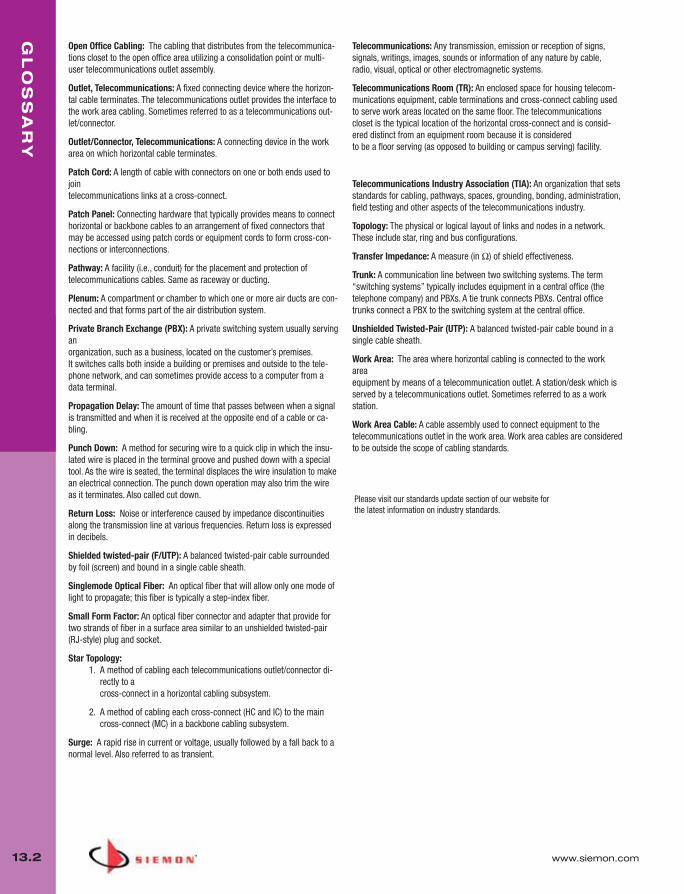
GL
OS
SA
RY
13.2 www.siemon.com
Open Office Cabling: The cabling that distributes from the telecommunica-tions closet to the open office area utilizing a consolidation point or multi-user telecommunications outlet assembly.
Outlet, Telecommunications: A fixed connecting device where the horizon-tal cable terminates. The telecommunications outlet provides the interface tothe work area cabling. Sometimes referred to as a telecommunications out-let/connector.
Outlet/Connector, Telecommunications: A connecting device in the workarea on which horizontal cable terminates.
Patch Cord: A length of cable with connectors on one or both ends used tojointelecommunications links at a cross-connect.
Patch Panel: Connecting hardware that typically provides means to connecthorizontal or backbone cables to an arrangement of fixed connectors thatmay be accessed using patch cords or equipment cords to form cross-con-nections or interconnections.
Pathway: A facility (i.e., conduit) for the placement and protection oftelecommunications cables. Same as raceway or ducting.
Plenum: A compartment or chamber to which one or more air ducts are con-nected and that forms part of the air distribution system.
Private Branch Exchange (PBX): A private switching system usually servinganorganization, such as a business, located on the customer’s premises. It switches calls both inside a building or premises and outside to the tele-phone network, and can sometimes provide access to a computer from adata terminal.
Propagation Delay: The amount of time that passes between when a signalis transmitted and when it is received at the opposite end of a cable or ca-bling.
Punch Down: A method for securing wire to a quick clip in which the insu-lated wire is placed in the terminal groove and pushed down with a specialtool. As the wire is seated, the terminal displaces the wire insulation to makean electrical connection. The punch down operation may also trim the wireas it terminates. Also called cut down.
Return Loss: Noise or interference caused by impedance discontinuitiesalong the transmission line at various frequencies. Return loss is expressedin decibels.
Shielded twisted-pair (F/UTP): A balanced twisted-pair cable surroundedby foil (screen) and bound in a single cable sheath.
Singlemode Optical Fiber: An optical fiber that will allow only one mode oflight to propagate; this fiber is typically a step-index fiber.
Small Form Factor: An optical fiber connector and adapter that provide fortwo strands of fiber in a surface area similar to an unshielded twisted-pair(RJ-style) plug and socket.
Star Topology: 1. A method of cabling each telecommunications outlet/connector di-
rectly to a cross-connect in a horizontal cabling subsystem.
2. A method of cabling each cross-connect (HC and IC) to the maincross-connect (MC) in a backbone cabling subsystem.
Surge: A rapid rise in current or voltage, usually followed by a fall back to anormal level. Also referred to as transient.
Telecommunications: Any transmission, emission or reception of signs, signals, writings, images, sounds or information of any nature by cable,radio, visual, optical or other electromagnetic systems.
Telecommunications Room (TR): An enclosed space for housing telecom-munications equipment, cable terminations and cross-connect cabling usedto serve work areas located on the same floor. The telecommunicationscloset is the typical location of the horizontal cross-connect and is consid-ered distinct from an equipment room because it is considered to be a floor serving (as opposed to building or campus serving) facility.
Telecommunications Industry Association (TIA): An organization that setsstandards for cabling, pathways, spaces, grounding, bonding, administration,field testing and other aspects of the telecommunications industry.
Topology: The physical or logical layout of links and nodes in a network.These include star, ring and bus configurations.
Transfer Impedance: A measure (in Ω) of shield effectiveness.
Trunk: A communication line between two switching systems. The term“switching systems” typically includes equipment in a central office (thetelephone company) and PBXs. A tie trunk connects PBXs. Central officetrunks connect a PBX to the switching system at the central office.
Unshielded Twisted-Pair (UTP): A balanced twisted-pair cable bound in asingle cable sheath.
Work Area: The area where horizontal cabling is connected to the workareaequipment by means of a telecommunication outlet. A station/desk which isserved by a telecommunications outlet. Sometimes referred to as a workstation.
Work Area Cable: A cable assembly used to connect equipment to the telecommunications outlet in the work area. Work area cables are consideredto be outside the scope of cabling standards.
Please visit our standards update section of our website forthe latest information on industry standards.
013_Glossary.qxd:ZMax_Catalog 1/4/10 12:11 PM Page 3
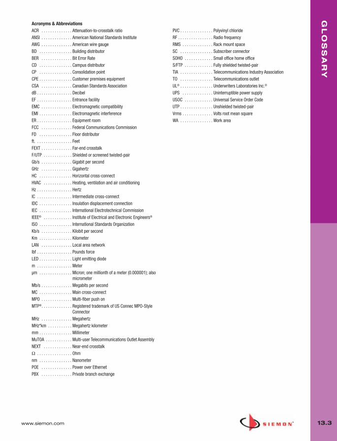
www.siemon.com
GL
OS
SA
RY
13.3
Acronyms & AbbreviationsACR . . . . . . . . . . . . . . Attenuation-to-crosstalk ratio
ANSI . . . . . . . . . . . . . . American National Standards Institute
AWG . . . . . . . . . . . . . . American wire gauge
BD . . . . . . . . . . . . . . . Building distributor
BER . . . . . . . . . . . . . . Bit Error Rate
CD . . . . . . . . . . . . . . . Campus distributor
CP . . . . . . . . . . . . . . . Consolidation point
CPE . . . . . . . . . . . . . . . Customer premises equipment
CSA . . . . . . . . . . . . . . Canadian Standards Association
dB . . . . . . . . . . . . . . . . Decibel
EF . . . . . . . . . . . . . . . . Entrance facility
EMC . . . . . . . . . . . . . . Electromagnetic compatibility
EMI . . . . . . . . . . . . . . . Electromagnetic interference
ER . . . . . . . . . . . . . . . . Equipment room
FCC . . . . . . . . . . . . . . Federal Communications Commission
FD . . . . . . . . . . . . . . . Floor distributor
ft. . . . . . . . . . . . . . . . . Feet
FEXT . . . . . . . . . . . . . . Far-end crosstalk
F/UTP . . . . . . . . . . . . . Shielded or screened twisted-pair
Gb/s . . . . . . . . . . . . . . Gigabit per second
GHz . . . . . . . . . . . . . . Gigahertz
HC . . . . . . . . . . . . . . . Horizontal cross-connect
HVAC . . . . . . . . . . . . . Heating, ventilation and air conditioning
Hz . . . . . . . . . . . . . . . . Hertz
IC . . . . . . . . . . . . . . . . Intermediate cross-connect
IDC . . . . . . . . . . . . . . . Insulation displacement connection
IEC . . . . . . . . . . . . . . . International Electrotechnical Commission
IEEE® . . . . . . . . . . . . . Institute of Electrical and Electronic Engineers®
ISO . . . . . . . . . . . . . . . International Standards Organization
Kb/s . . . . . . . . . . . . . . Kilobit per second
Km . . . . . . . . . . . . . . . Kilometer
LAN . . . . . . . . . . . . . . Local area network
lbf . . . . . . . . . . . . . . . . Pounds force
LED . . . . . . . . . . . . . . . Light emitting diode
m . . . . . . . . . . . . . . . . Meter
μm . . . . . . . . . . . . . . . Micron; one millionth of a meter (0.000001); also micrometer
Mb/s . . . . . . . . . . . . . . Megabits per second
MC . . . . . . . . . . . . . . . Main cross-connect
MPO . . . . . . . . . . . . . . Multi-fiber push on
MTP®. . . . . . . . . . . . . . Registered trademark of US Connec MPO-Style Connector
MHz . . . . . . . . . . . . . . Megahertz
MHz*km . . . . . . . . . . . Megahertz kilometer
mm . . . . . . . . . . . . . . . Millimeter
MuTOA . . . . . . . . . . . . Multi-user Telecommunications Outlet Assembly
NEXT . . . . . . . . . . . . . Near-end crosstalk
Ω . . . . . . . . . . . . . . . . Ohm
nm . . . . . . . . . . . . . . . Nanometer
POE . . . . . . . . . . . . . . Power over Ethernet
PBX . . . . . . . . . . . . . . Private branch exchange
PVC . . . . . . . . . . . . . . . Polyvinyl chloride
RF . . . . . . . . . . . . . . . . Radio frequency
RMS . . . . . . . . . . . . . . Rack mount space
SC . . . . . . . . . . . . . . . Subscriber connector
SOHO . . . . . . . . . . . . . Small office home office
S/FTP . . . . . . . . . . . . . Fully shielded twisted-pair
TIA . . . . . . . . . . . . . . . Telecommunications Industry Association
TO . . . . . . . . . . . . . . . Telecommunications outlet
UL® . . . . . . . . . . . . . . . Underwriters Laboratories Inc.®
UPS . . . . . . . . . . . . . . Uninterruptible power supply
USOC . . . . . . . . . . . . . Universal Service Order Code
UTP . . . . . . . . . . . . . . . Unshielded twisted-pair
Vrms . . . . . . . . . . . . . . Volts root mean square
WA . . . . . . . . . . . . . . . Work area
013_Glossary.qxd:ZMax_Catalog 1/4/10 12:11 PM Page 4
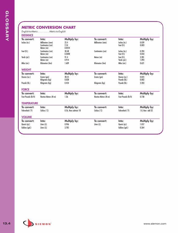
GL
OS
SA
RY
13.4 www.siemon.com
METRIC CONVERSION CHARTEnglish-to-Metric . . . . . . . . Metric-to-EnglishDISTANCETo convert: Into: Multiply by: To convert: Into: Multiply by:Inches (in.) Millimeters (mm) 25.4 Millimeters (mm) Inches (in.) 0.039
Centimeters (cm) 2.54 Feet (ft.) 0.003Meters (m) 0.0254
Feet (ft.) Centimeters (cm) 30.48 Centimeters (cm) Inches (in.) 0.394Meters (m) 0.3048 Feet (ft.) 0.033
Yards (yd.) Centimeters (cm) 91.4 Meters (m) Feet (ft.) 3.281Meters (m) 0.914 Yards (yd.) 1.093
Miles (mi.) Kilometers (km) 1.609 Kilometers (km) Miles (mi.) 0.621
WEIGHTTo convert: Into: Multiply by: To convert: Into: Multiply by:Ounces (oz.) Grams (gm) 28.35 Grams (gm) Ounces (oz.) 0.035
Kilograms (kg) 0.028 Pounds (lb.) 0.002Pounds (lb.) Kilograms (kg) 0.454 Kilograms (kg) Pounds (lb.) 2.203
FORCETo convert: Into: Multiply by: To convert: Into: Multiply by:Foot Pounds (lb-ft) Newton Meters (N-m) 1.36 Newton Meters (N-m) Foot Pounds (lb-ft) 0.738
TEMPERATURETo convert: Into: Multiply by: To convert: Into: Multiply by:Fahrenheit (˚F) Celsius (˚C) 0.56, then subtract 18 Celsius (˚C) Fahrenheit (˚F) 1.8, then add 32
VOLUMETo convert: Into: Multiply by: To convert: Into: Multiply by:Quarts (qt.) Liters (L) 0.946 Liters (L) Quarts (qt.) 1.057Gallons (gal.) Liters (L) 3.785 Gallons (gal.) 0.264
013_Glossary.qxd:ZMax_Catalog 1/4/10 12:11 PM Page 5

www.siemon.com
WA
RR
AN
TY
13.5
• A one (1) year repair or replace warranty on Tools and
Testers and active electronics (ie MapIT G2)
• A five (5) year repair or replace warranty for all Siemon
Products (cabling system connecting hardware) when
not installed in a certified Siemon Cabling System®
• An extended Siemon Cabling System Warranty covering
application assurance, product, quality and performance
margins when designed and installed by Siemon
Certified InstallerSM and registered with Siemon.
Please contact your local Siemon Company sales office or visit Siemon’s website for more information.
Warranty
Siemon delivers a full range of product and system warranty programs:
Siemon warrants its products to be free from
defects in material and workmanship. Should any
product fail to conform, Siemon will, upon written
notice from Distributor of such non-conforming
product, within five (5) years after date of
purchase, either replace it F.O.B. original point-of-
delivery, or refund the purchase price, at Siemon’s
option, and shall have the right to require
Distributor to return the defective product to
Siemon’s plant unless such return is
impracticable. The remedies provided herein shall
be Buyer’s sole and exclusive remedies, and no
statement or recommendation not contained
herein shall have any force or effect unless in
writing and signed by an authorized officer of
Siemon. Siemon makes no warranty, expressed or
implied, as to merchantability or fitness for a
particular purpose of any product sold. In no event
will Siemon be liable for any special incidental, or
consequential damages, where asserted in
contract, tort, or otherwise. This warranty applies
only to those cabling products that are used to
terminate or cross-connect telecommunications
cabling. Warranty terms for other categories of
cabling products (e.g., tools, test equipment,
protection apparatus, etc.) may vary.
Limited Five (5) Year Product Warranty
013_Glossary.qxd:ZMax_Catalog 1/4/10 12:11 PM Page 6

IND
EX
14.0 www.siemon.com
7
700A-66-B1-25 . . . . . . . . . . . 11.7
10G
10GBPS-(XX)M-(XX)L . . . . . . . .2.710GMX-FPD(XX)-(XX) . . . . . . . .9.310GMX-FPS(XX)-(XX) . . . . . . . .9.310GMX-HFP-(XX)(X) . . . . . . . . .9.5
9
9A5L4-E2 . . . . . . . . . . . . . . . . .4.69A5M4-E2 . . . . . . . . . . . . . . . .4.69A5P4-E1-(XX)-R1A . . . . . . . . .4.59A5R4-E1-(XX)-R1A . . . . . . . . .4.59A5R4-E2 . . . . . . . . . . . . . . . . .4.69A6L4-A5 . . . . . . . . . . . . . . . .2.129A6M4-A5 . . . . . . . . . . . . . . .2.129A6P4-A5-(XX)-R1A . . . . . . . .2.119A6R4-A5 . . . . . . . . . . . . . . .2.129A6R4-A5-(XX)-R1A . . . . . . . .2.119BB(X)(X)002B-(XX)09A . . . . .6.199BB(X)(X)004C-(XX)09A . . . . .6.199BB(X)(X)006D-(XX)09A . . . . .6.199BB(X)(X)008E-(XX)09A . . . . .6.199BB(X)(X)012G-(XX)09A . . . . .6.199BB(X)(X)016C-(XX)09A . . . . .6.199BB(X)(X)024L-(XX)09A . . . . .6.199BB(X)(X)036D-(XX)09A . . . . .6.199BB(X)(X)048G-(XX)09A . . . . .6.199BB(X)(X)072G-(XX)09A . . . . .6.199BB5(X)002B-T312A . . . . . . .6.169BB5(X)004C-T312A . . . . . . .6.169BB5(X)006D-T312A . . . . . . .6.169BB5(X)008E-T312A . . . . . . . .6.169BB5(X)012G-T312(Y) . . . . . .6.169BB5(X)016C-T312A . . . . . . .6.169BB5(X)024L-T312(Y) . . . . . . .6.169BB5(X)036D-T312A . . . . . . .6.169BB5(X)048G-T312A . . . . . . .6.169BB5(X)072G-T312A . . . . . . .6.169BB8(X)002B-E205A . . . . . . .6.169BB8(X)004C-E205A . . . . . . .6.169BB8(X)006D-E205A . . . . . . .6.169BB8(X)008E-E205A . . . . . . . .6.169BB8(X)012G-E205A . . . . . . .6.169BB8(X)016C-E205A . . . . . . .6.16
9BB8(X)024L-E205A . . . . . . . .6.169BB8(X)036D-E205A . . . . . . .6.169BB8(X)048G-E205A . . . . . . .6.169BB8(X)072G-E205A . . . . . . .6.169BC(X)(X)006D-(XXXX)A . . . . .6.239BC(X)(X)012G-(XXXX)A . . . . .6.239BC(X)(X)024L-(XXXX)A . . . . .6.239BC(X)(X)036G-(XXXX)A . . . . .6.239BC(X)(X)048G-(XXXX)A . . . . .6.239BC(X)(X)072G-(XXXX)A . . . . .6.239BC(X)(X)096G-(XXXX)A . . . . .6.239BC(X)(X)144G-(XXXX)A . . . . .6.239C5L4-E2 . . . . . . . . . . . . . . . .5.129C5M4-E2 . . . . . . . . . . . . . . .5.129C5P4-E2-(XX)-RXA . . . . . . . .5.119C5R4-E2 . . . . . . . . . . . . . . . .5.129C5R4-E2-(XX)-RXA . . . . . . . .5.119C6L4-E3 . . . . . . . . . . . . . . . .3.189C6M4-E3 . . . . . . . . . . . . . . .3.189C6P4-A5-(XX)-R1A . . . . . . . .2.199C6P4-E3-(XX)-RXA . . . . . . . .3.179C6P4-E4-(XX) . . . . . . . . . . . .3.169C6R4-A5-(XX)-R1A . . . . . . . .2.199C6R4-E3 . . . . . . . . . . . . . . . .3.189C6R4-E3-(XX)-RXA . . . . . . . .3.179C6R4-E4-(XX) . . . . . . . . . . . .3.169F(X)B(X)-12D(XXXX) . . . . . . .6.219F(X)B(X)-16A(XXXX) . . . . . . .6.219F(X)B(X)-24B(XXXX) . . . . . . .6.219F(X)B(X)-2F(XXXX) . . . . . . . . .6.219F(X)B(X)-48D(XXXX) . . . . . . .6.219F(X)B(X)-4A(XXXX) . . . . . . . .6.219F(X)B(X)-6B(XXXX) . . . . . . . .6.219F(X)B(X)-72D(XXXX) . . . . . . .6.219F(X)B(X)-8C(XXXX) . . . . . . . .6.219F5LB(X)-12D(XXXX) . . . . . . .6.179F5LB(X)-16A(XXXX) . . . . . . .6.179F5LB(X)-24B(XXXX) . . . . . . . .6.179F5LB(X)-2F(XXXX) . . . . . . . . .6.179F5LB(X)-48D(XXXX) . . . . . . .6.179F5LB(X)-4A(XXXX) . . . . . . . .6.179F5LB(X)-6B(XXXX) . . . . . . . . .6.179F5LB(X)-72D(XXXX) . . . . . . .6.179F5LB(X)-8C(XXXX) . . . . . . . . .6.179F8LB(X)-12D(XXXX) . . . . . . .6.179F8LB(X)-16A(XXXX) . . . . . . .6.179F8LB(X)-24B(XXXX) . . . . . . . .6.179F8LB(X)-2F(XXXX) . . . . . . . . .6.179F8LB(X)-48D(XXXX) . . . . . . .6.179F8LB(X)-4A(XXXX) . . . . . . . .6.179F8LB(X)-6B(XXXX) . . . . . . . . .6.179F8LB(X)-72D(XXXX) . . . . . . .6.179F8LB(X)-8C(XXXX) . . . . . . . . .6.179T7L4-E10 . . . . . . . . . . . . . . . .1.8
9T7P4-E10-06-R1 . . . . . . . . . . .1.79T7R4-E10-06-R1 . . . . . . . . . . .1.7
A
AB . . . . . . . . . . . . . . . . . . . . . .9.7
B
BP6A-(XX)-(XX) . . . . . . . . . . . .2.16BP5S-(XX)M-(XX) . . . . . . . . . . .4.3BP6-(XX)-(XX) . . . . . . . . . . . . . .3.9
C
CF-(XX) . . . . . . . . . . . . . . . . . . .7.6CI-KIT . . . . . . . . . . . . . . . . . . .12.6CI-KIT2 . . . . . . . . . . . . . . . . . .12.6CI-POUCH . . . . . . . . . . . . . . . .12.6CI-POUCH2 . . . . . . . . . . . . . . .12.6CI-SCISSORS . . . . . . . . . . . . .6.12CJ5-W1-1000-03 . . . . . . . . . .5.10CJ5-W1-1000-06 . . . . . . . . . .5.10CJ5-W2-1000 . . . . . . . . . . . . .5.10CJ5-W2-1000-07 . . . . . . . . . .5.10CJ6-W4-1000 . . . . . . . . . . . . .3.13CLIP-(XX) . . . . . . . . .1.5, 2.6, 2.15CPT . . . . . . . . . . . . . . . . . . . . .12.7CPT-DIE-RG . . . . . . . . . . . . . .12.7CPT-DIE-T4 . . . . . . . . . . . . . . .12.7CPT-DIE-TMPL . . . . . . . . . . . .12.7CPT-DIE-TP . . . . . . . . . .12.3, 12.7CPT-RGTP . . . . . . . . . . .12.3, 12.7CPT-T . . . . . . . . . . . . . . . . . . .12.7CPT-WEB . . . . . . . . . . . . . . . .12.7CT2-FP-(XX) . . . . . . . . . . . . . .9.12CT2-HFPA-(XX) . . . . . . . . . . . .9.12CT4-BOX-(XX) . . . . . . . . . . . . . .9.7CT4-FP-(XX) . . . . . . . . . . . . . .9.12CT4-RING-050-(XX) . . . . . . . . .9.7CT4-RING-100-(XX) . . . . . . . . .9.7CT8-BOX-(XX) . . . . . . . . . . . . . .9.7CT8-FP-(XX) . . . . . . . . . . . . . .9.12CT8-RING-050-(XX) . . . . . . . . .9.7CT8-RING-100-(XX) . . . . . . . . .9.7CTE-MXA-01-02 . . . . . . . . . . .9.12CTE-MXA-02-02 . . . . . . . . . . .9.12CT-FP-LBL-104 . . . . . . . . . . . . .9.6CT-MFP-(XX) . . . . . . . . . . . . . .9.12
CT-MFP-HMA-(XX) . . . . . . . . .9.12CT-MMO-MAG . . . . . . . . . . . .9.10
F
FC1-LC-MM-B02 . . . . . . . . . .6.11FC1-LC-MM-B80 . . . . . . . . . .6.11FC1-LC-MM-B80 . . . . . . . . . .11.6FC1-LC-MM-J02 . . . . . . . . . .6.11FC1-LC-MM-J80 . . . . . . . . . .6.11FC1M-LC-5L-B12 . . . . . . . . . . .6.9FC1M-LC-5MM-B01 . . . . . . . . .6.9FC1M-LC-6MM-B80 . . . . . . . . .6.9FC1M-LC-SM-B06 . . . . . . . . . .6.9FC1M-SC-5L-B12 . . . . . . . . . . .6.9FC1M-SC-5MM-B01 . . . . . . . .6.9FC1M-SC-6MM-B80 . . . . . . . .6.9FC1M-SC-SM-B06 . . . . . . . . . .6.9FC1-SA-MM-B80 . . . . . . . . . .6.10FC1-SA-MM-J80 . . . . . . . . . .6.10FC1-SC-MM-B80 . . . . . . . . . .6.10FC1-SC-MM-J80 . . . . . . . . . .6.10FC1-SC-SM-B06 . . . . . . . . . . .6.10FC1-SC-SM-J06 . . . . . . . . . . .6.10FC1-ST-SM-J06 . . . . . . . . . . .6.10FC2-LC-MM-J80 . . . . . . . . . .11.6FC2-SC-MM-B80 . . . . . . . . . .6.10FC2-SC-MM-J . . . . . . . . . . . .6.10FC2-SC-SM-B06 . . . . . . . . . . .6.10FC2-SC-SM-J06 . . . . . . . . . . .6.10FC2-ST-SM-B06 . . . . . . . . . . .6.10FCP3-DWR . . . . . . . . . . . . . . . .7.6FCP3-RACK . . . . . . . . . . . . . . . .7.6FE(XXX)-(XX)(X)(XXX)(X) . . . . . .6.3FJ2-LCLC5L-(XX)AQ . . . . . . . . .6.5FJ2-LCLC5MM-(XX) . . . . . . . . .6.6FJ2-LCLC6MM-(XX) . . . . . . . . .6.6FJ2-LCSA5MM-(XX) . . . . . . . . .6.6FJ2-LCSA6MM-(XX) . . . . . . . . .6.6FJ2-LCSC5L-(XX)AQ . . . . . . . . .6.5FJ2-LCSC5MM-(XX) . . . . . . . . .6.6FJ2-LCSC6MM-(XX) . . . . . . . . .6.6FJ2-LCULCUL-(XX) . . . . . . . . . .6.5FJ2-LCUSAUL-(XX) . . . . . . . . . .6.5FJ2-LCUSCUL-(XX) . . . . . . . . . .6.5FJ2-SASA5MM-(XX) . . . . . . . .6.6FJ2-SASA6MM-(XX) . . . . . . . .6.6FJ2-SASC5MM-(XX) . . . . . . . .6.6FJ2-SASC6MM-(XX) . . . . . . . .6.6FJ2-SAUSAUL-(XX) . . . . . . . . .6.5FJ2-SAUSCUL-(XX) . . . . . . . . .6.5FJ2-SCSC5L-(XX)AQ . . . . . . . . .6.5FJ2-SCSC5MM-(XX) . . . . . . . .6.6
014_Index_RevB.qxd:ZMax_Catalog 2/12/10 4:18 PM Page 1

www.siemon.com
IND
EX
14.1
FJ2-SCSC6MM-(XX) . . . . . . . .6.6FJ2-SCUSCUL-(XX) . . . . . . . . . .6.5FJ-MMLC(XX)(X)(XX)(X) . . . . . .6.4FMT . . . . . . . . . . . . . . . . . . . .9.10FOB2-(XX) . . . . . . . . . . . . . . . .9.11FOB2-GRD-(XX) . . . . . . . . . . .9.11FOB-BZL-BL-01 . . . . . . . . . . . .9.11FOB-BZL-LC(X)-01 . . . . . . . . . .9.11FOB-BZL-LC(X)1-01 . . . . . . . . .9.11FOB-BZL-SA-01 . . . . . . . . . . .9.11FOB-BZL-SC-01 . . . . . . . . . . .9.11FP1B-LC5MM-01 . . . . . . . . . . .6.6FP1B-LC6MM-01 . . . . . . . . . . .6.6FP1B-LCUL-01 . . . . . . . . . . . . .6.5FP1B-SA5MM-01 . . . . . . . . . . .6.6FP1B-SA6MM-01 . . . . . . . . . . .6.6FP1B-SAUL-01 . . . . . . . . . . . . .6.5FP1B-SC5MM-01 . . . . . . . . . . .6.6FP1B-SC6MM-01 . . . . . . . . . . .6.6FP1B-SCUL-01 . . . . . . . . . . . . .6.5FR(XXX)-(XX)(X)(XXX)(X)C . . . . .6.2FT-ADH-L . . . . . . . . . . . . . . . .6.12FT-ALPAD . . . . . . . . . . . . . . . .6.12FT-BSTRP . . . . . . . . . . . . . . . .6.12FT-CKIT-L2 . . . . . . . . . . . . . . .6.12FT-CRIMP . . . . . . . . . . . . . . . .6.12FTERM-L2 . . . . . . . . . . . . . . . .6.11FTERM-LC . . . . . . . . . . . . . . .6.11FTERM-XLC . . . . . . . . . . . . . .11.6FTERM-XLR8 . . . . . . . . . . . . . .6.8FTERM-XLR8-A . . . . . . . . . . . .6.8FTERM-XLR8-C . . . . . . . . . . . . .6.8FT-FF . . . . . . . . . . . . . . . . . . . .6.12FT-JSTRP . . . . . . . . . . . . . . . .6.12FT-LC2PUCK . . . . . . . . . . . . . .11.6FT-LCPUCK . . . . . . . . . . . . . . .6.12FT-MS400 . . . . . . . . . . . . . . . .6.12FT-MSLC2HEAD . . . . . . . . . . .6.12FT-PAD . . . . . . . . . . . . . . . . . .6.12FT-PF1 . . . . . . . . . . . . . . . . . . .6.12FT-PF12 . . . . . . . . . . . . . . . . . .6.12FT-PF3 . . . . . . . . . . . . . . . . . . .6.12FT-PF6 . . . . . . . . . . . . . . . . . . .6.12FT-PRBOT-L . . . . . . . . . . . . . . .6.12FT-PUCK . . . . . . . . . . . . . . . . .6.12FT-SCRIBE . . . . . . . . . . . . . . .6.12FT-SYRMTIP . . . . . . . . . . . . . .6.12FT-TMPL . . . . . . . . . . . . . . . . .6.12FT-WIPES . . . . . . . . . . . . . . . .6.12
H
HD5-16 . . . . . . . . . . . . . . . . . . .5.3
HD5-24 . . . . . . . . . . . . . . . . . . .5.3
HD5-32 . . . . . . . . . . . . . . . . . . .5.3
HD5-48 . . . . . . . . . . . . . . . . . . .5.3
HD5-89D-12 . . . . . . . . . . . . . . .5.3
HD5-96 . . . . . . . . . . . . . . . . . . .5.3
HD5-ICON6 . . . . . . . . . . . .3.5, 4.2
HD5-ICON6-LBL . . . . . . . .3.5, 4.2
HD5-LBL-480 . . . . . . . . . . .3.5, 4.2
HD5-LBL6-2 . . . . . . . . . . . .3.5, 4.2
HD5-RWM . . . . . . . . . . . . . . . .4.2
HD5-S-24 . . . . . . . . . . . . . . . . .4.2
HD6-16 . . . . . . . . . . . . . . . . . . .3.4
HD6-24 . . . . . . . . . . . . . . . . . . .3.4
HD6-48 . . . . . . . . . . . . . . . . . . .3.4
HD6-89D-12 . . . . . . . . . . . . . . .3.5
HD6-96 . . . . . . . . . . . . . . . . . . .3.4
HD-RWM . . . . . . . . . . . . . . . . .3.5
HT-40 . . . . . . . . . . . . . . . . . . . .7.7
HT-60 . . . . . . . . . . . . . . . . . . . .7.7
I
IC5-8A-(XX)-B(XX)P . . . . . . . . .5.6IC5-8A-(XX)-B(XX)R . . . . . . . . .5.6IC5-8A-(XX)P . . . . . . . . . . . . . .5.6IC5-8A-(XX)R . . . . . . . . . . . . . .5.6IC5-8T-(XX)-B(XX)P . . . . . . . . . .5.6IC5-8T-(XX)-B(XX)R . . . . . . . . . .5.6IC5-8T-(XX)P . . . . . . . . . . . . . . .5.6IC5-8T-(XX)R . . . . . . . . . . . . . . .5.6IC6-8A-(XX)-B(XX)P . . . . . . . .3.11IC6-8A-(XX)-B(XX)R . . . . . . . .3.11IC6-8T-(XX)-B(XX)P . . . . . . . . .3.11IC6-8T-(XX)-B(XX)R . . . . . . . . .3.11IC6E-8A-(XX)-B(XX)P . . . . . . .3.11IC6E-8A-(XX)-B(XX)R . . . . . . .3.11IC6E-8T-(XX)-B(XX)P . . . . . . . .3.11IC6E-8T-(XX)-B(XX)R . . . . . . . .3.11
J
J2-LCLC5-(XX) . . . . . . . . . . . . .6.7J2-LCLC6-(XX) . . . . . . . . . . . . .6.7J2-LCLCP-(XX) . . . . . . . . . . . . .6.7J2-LCSA5-(XX) . . . . . . . . . . . . .6.7J2-LCSA6-(XX) . . . . . . . . . . . . .6.7J2-LCSAP-(XX) . . . . . . . . . . . . .6.7J2-LCSC5-(XX) . . . . . . . . . . . . .6.7
J2-LCSC6-(XX) . . . . . . . . . . . . .6.7J2-LCSCP-(XX) . . . . . . . . . . . . .6.7J2-SASA5-(XX) . . . . . . . . . . . . .6.7J2-SASA6-(XX) . . . . . . . . . . . . .6.7J2-SASAP-(XX) . . . . . . . . . . . . .6.7J2-SASC5-(XX) . . . . . . . . . . . . .6.7J2-SASC6-(XX) . . . . . . . . . . . . .6.7J2-SASCP-(XX) . . . . . . . . . . . . .6.7J2-SCSC5-(XX) . . . . . . . . . . . . .6.7J2-SCSC6-(XX) . . . . . . . . . . . . .6.7J2-SCSCP-(XX) . . . . . . . . . . . . .6.7
L
LKEY-05 . . . . . . . . . . . . . . . . . .9.2LL-05 . . . . . . . . . . . . . . . . . . . .9.2LP6-(XX)-(XX) . . . . . . . . . . . . . .9.2LP6A-(XX)-(XX) . . . . . . . . . . . . .9.2LP6A-S(XX)M-(XX)L . . . . . . . . .9.2
M
M-10GMC-(XX)-(XX) . . . . . . . . .8.4M-10GMCS-(XX)M(XX)L . . . . .8.4M1-50 . . . . . . . . . . . . . . . . . .5.10MB . . . . . . . . . . . . . . . . . . . . . .9.7MC5-8-T-(XX)(XX) . . . . . . . . . . .5.5MC5-8T-(XX)-B(XX) . . . . . . . . . .5.5MC5S-(XX)M-(XX) . . . . . . . . . .4.4MC6-8-T-(XX)-(XX) . . . . . . . . .3.10MC-8-OO5 . . . . . . . . . . . . . . .12.2MC-S-8-005 . . . . . . . . . . . . . .12.2M-DCP . . . . . . . . . . . . . . . . . . .8.2M-J2-LCLC5L-(XX) . . . . . . . . . .8.6M-J2-LCULCUL-(XX) . . . . . . . . .8.6M-MC6-(XX)-(XX) . . . . . . . . . . .8.4M-MCP . . . . . . . . . . . . . . . . . . .8.2M-PEN . . . . . . . . . . . . . . . . . . .8.2M-PS . . . . . . . . . . . . . . . . . . . .8.2M-SFE-LC48-01 . . . . . . . . . . . .8.5M-SPP-K24E . . . . . . . . . . . . . . .8.3MX5-(XX) . . . . . . . . . . . . . . . . .5.1MX5-F(XX) . . . . . . . . . . . . . . . .5.1MX5-FS . . . . . . . . . . . . . . . . . .4.1MX5-K(XX) . . . . . . . . . . . . . . . .5.1MX5-KS . . . . . . . . . . . . . . . . . .4.1MX5-S . . . . . . . . . . . . . . . . . . .4.1MX6-(XX) . . . . . . . . . . . . . . . . .3.2MX6-F(XX) . . . . . . . . . . . . . . . .3.2MX6-K(XX) . . . . . . . . . . . . . . . .3.2MX-89D-12 . . . . . . . . . . . .3.8, 5.4
MX-AD-(XX) . . . . . . . . . . . . . . .9.5MX-BL-(XX) . . . . . . . . . . . . . . .9.5MX-C5-(XX) . . . . . . . . . . . . . . .5.2MX-F-C5-(XX) . . . . . . . . . . . . . .5.2MX-FD-(XX) . . . . . . . . . . . . . . .9.5MX-FP-CVR-00 . . . . . . . . . . . . .9.6MX-FP-D-(XX)(XX) . . . . . . . . . .9.4MX-FP-D-(XX)-SS-(X) . . . . . . . .9.4MX-FP-S-(XX)(XX) . . . . . . . . . . .9.4MX-FP-S-(XX)-SS-(X) . . . . . . . .9.4MX-HFP-(XX)(X) . . . . . . . . . . . .9.5MX-K-C5-(XX) . . . . . . . . . . . . . .5.2MX-MFP-(XX) . . . . . . . . . . . . . .9.6MX-MFP-A03-(XX) . . . . . . . . . .9.6MX-MFP-HMA-(XX) . . . . . . . . .9.6MX-MFP-HME-01 . . . . . . . . . .9.6MX-MFP-KNL-01 . . . . . . . . . . .9.6MX-MMO-(XX) . . . . . . . . . . . .9.10MX-PNL-16 . . . . . . . . . . . .3.7, 5.4MX-PNL-24 . . . . . . . . . . . .3.7, 5.4MX-PNL-48 . . . . . . . . . . . .3.7, 5.4MX-PNL-72 . . . . . . . . . . . .3.7, 5.4MX-PNLA-24 . . . . . . . . . . .3.7, 5.4MX-PNLA-48 . . . . . . . . . . .3.7, 5.4MX-PNL-LBL4 . . . . . . . . . .3.8, 5.4MX-PNL-LBL6 . . . . . . . . . .3.8, 5.4MX-SM1-(XX) . . . . . . . . . . . . . .9.9MX-SM2-(XX) . . . . . . . . . . . . . .9.9MX-SM4-(XX) . . . . . . . . . . . . . .9.9MX-SM6-(XX) . . . . . . . . . . . . . .9.9MX-SM-BLNK-(XX) . . . . . . . . .9.9MX-SMB-MM-(XX) . . . . . . . . .9.9MX-SMB-SC-(XX) . . . . . . . . . . .9.9MX-SMZ(X)-(XX) . . . . . . . . . . .9.8MX-TFP-S-06-(XX) . . . . . . . . . .9.7
P
P1B-LC5-01 . . . . . . . . . . . . . . .6.7P1B-LC6-01 . . . . . . . . . . . . . . .6.7P1B-LCP-01 . . . . . . . . . . . . . . .6.7P1B-SA5-01 . . . . . . . . . . . . . . .6.7P1B-SA6-01 . . . . . . . . . . . . . . .6.7P1B-SAP-01 . . . . . . . . . . . . . . .6.7P1B-SC5-01 . . . . . . . . . . . . . . .6.7P1B-SC6-01 . . . . . . . . . . . . . . .6.7P1B-SCP-01 . . . . . . . . . . . . . . .6.7PG . . . . . . . . . . . . . . . . . . . . .12.6PH-3 . . . . . . . . . . . . . . . . . . .10.11PNL-BLNK-(X) . . . . . . . . . . . . .10.6PP2-12-(XX)(X)-01 . . . . . . . . . . .6.1PP2-24-LC(X)-01 . . . . . . . . . . . .6.1
014_Index_RevB.qxd:ZMax_Catalog 2/12/10 4:18 PM Page 2
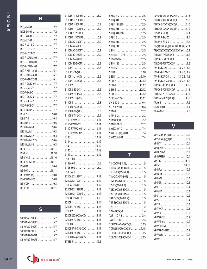
IND
EX
14.2 www.siemon.com
R
RIC3-24-01 . . . . . . . . . . . . . . . .7.2RIC3-36-01 . . . . . . . . . . . . . . . .7.2RIC3-48-01 . . . . . . . . . . . . . . . .7.2RIC3-72-01 . . . . . . . . . . . . . . . .7.2RIC-F-LC12-01 . . . . . . . . . . . . .7.7RIC-F-LC16-01 . . . . . . . . . . . . .7.7RIC-F-LC24-01 . . . . . . . . . . . . .7.7RIC-F-LCU12-01 . . . . . . . . . . . .7.7RIC-F-LCU16-01 . . . . . . . . . . . .7.7RIC-F-LCU24-01 . . . . . . . . . . . .7.7RIC-F-MP-12-01 . . . . . . . . . . . .6.1RIC-F-MP-24-01 . . . . . . . . . . . .6.1RIC-F-MP-72-01 . . . . . . . . . . . .6.1RIC-F-SA12-01 . . . . . . . . . . . . .7.7RIC-F-SA6-01 . . . . . . . . . . . . . .7.7RIC-F-SA8-01 . . . . . . . . . . . . . .7.7RIC-F-SC12-01 . . . . . . . . . . . . .7.7RIC-F-SC6-01 . . . . . . . . . . . . . .7.7RIC-F-SC8-01 . . . . . . . . . . . . . .7.7RIF-F-BLNK . . . . . . . . . . . . . . . .7.7RS-07E . . . . . . . . . . . . . . . . . .10.8RS-07-S . . . . . . . . . . . . . . . . .10.8RS3-07-S . . . . . . . . . . . . . . . .10.6RS3-RWM-(X) . . . . . . . . . . . .10.6RS3-RWM-1 . . . . . . . . . . . . . .10.3RS3-RWM-2 . . . . . . . . . . . . . .10.3RS3-RWM-2DS . . . . . . . . . . .10.6RS3-RWM-4 . . . . . . . . . . . . . .10.3RS-CH . . . . . . . . . . . . . . . . . .10.11RS-CNL . . . . . . . . . . . . . . . . .10.10RS-CNL3 . . . . . . . . . . . . . . . .10.10RS-CNL-MGR . . . . . . . . . . . .10.11RS-P04 . . . . . . . . . . . . . . . . . .10.4RS-P04 . . . . . . . . . . . . . . . . .10.11RS-RWM-(X) . . . . . . . . . . . . .10.8RS-RWM-2DS . . . . . . . . . . . .10.8RS-VCM . . . . . . . . . . . . . . . . .10.3RS-VCM . . . . . . . . . . . . . . . .10.11
S
S110AA1-50FT . . . . . . . . . . . . .5.7S110AA2-100FT . . . . . . . . . . . .5.7S110AA2-300FT . . . . . . . . . . . .5.7S110AB1-50FT . . . . . . . . . . . . .5.7S110AB2-100FT . . . . . . . . . . . .5.7S110AB2-300FT . . . . . . . . . . . .5.7
S110DA1-100RFT . . . . . . . . . . .5.9S110DA1-200RFT . . . . . . . . . . .5.9S110DA1-300RFT . . . . . . . . . . .5.9S110DB1-100RFT . . . . . . . . . . .5.9S110DB1-200RFT . . . . . . . . . . .5.9S110DB1-300RFT . . . . . . . . . . .5.9S110MA2-300FT . . . . . . . . . . .5.9S110MA2-400FT . . . . . . . . . . .5.9S110MA2-500FT . . . . . . . . . . .5.9S110MB2-300FT . . . . . . . . . . .5.9S110MB2-400FT . . . . . . . . . . .5.9S110MB2-500FT . . . . . . . . . . .5.9S110P1 . . . . . . . . . . . . . . . . . . .5.8S110P1-P1-(XX) . . . . . . . . . . . .5.8S110P1-U1-(XX) . . . . . . . . . . . .5.6S110P1-U4-(XX) . . . . . . . . . . . .5.6S110P2 . . . . . . . . . . . . . . . . . . .5.8S110P2-E2-(XX) . . . . . . . . . . . .5.6S110P2-PS-(XX) . . . . . . . . . . . .5.8S110P2-UT-(XX) . . . . . . . . . . . .5.6S110P4 . . . . . . . . . . . . . . . . . . .5.8S110P4-A4-(XX) . . . . . . . . . . . .5.6S110P4-P4-(XX) . . . . . . . . . . . .5.8S110P4-T4-(XX) . . . . . . . . . . . .5.6S110-RWM-01 . . . . . . . . . . .10.11S110-RWM-02 . . . . . . . . . . .10.11S110-RWM2-01 . . . . . . . . . .10.11S110-RWM2-02 . . . . . . . . . .10.11S143 . . . . . . . . . . . . . . . . . . .10.12S144 . . . . . . . . . . . . . . . . . . .10.12S145 . . . . . . . . . . . . . . . . . . .10.12S146 . . . . . . . . . . . . . . . . . . .10.12S147 . . . . . . . . . . . . . . . . . . .10.12S188-300 . . . . . . . . . . . . . . . . .5.9S188-400 . . . . . . . . . . . . . . . . .5.9S188-500 . . . . . . . . . . . . . . . . .5.9S188-WD . . . . . . . . . . . . . . . . .5.9S210AB2-128FT . . . . . . . . . . .3.12S210AB2-192FT . . . . . . . . . . .3.12S210AB2-64FT . . . . . . . . . . . .3.12S210DB2-128RFT . . . . . . . . . .3.13S210DB2-192RFT . . . . . . . . . .3.13S210DB2-64RFT . . . . . . . . . . .3.13S210P1 . . . . . . . . . . . . . . . . . .3.14S210P1-P1-(XX) . . . . . . . . . . .3.14S210P2 . . . . . . . . . . . . . . . . . .3.14S210P2E2-(XX)-(XX) . . . . . . . .3.11S210P2-P2-(XX) . . . . . . . . . . .3.14S210P4 . . . . . . . . . . . . . . . . . .3.14S210P4A4-(XX)-(XX) . . . . . . . .3.11S210P4-P4-(XX) . . . . . . . . . . .3.14S210P4T4-(XX)-(XX) . . . . . . . .3.11S788J4 . . . . . . . . . . . . . . . . . .12.5
S788J4-210 . . . . . . . . . . . . . .12.5S788J4B . . . . . . . . . . . . . . . . .12.5S788J4B-210 . . . . . . . . . . . . .12.5S788J4H . . . . . . . . . . . . . . . .12.5S788J4H-210 . . . . . . . . . . . . .12.5S788J5 . . . . . . . . . . . . . . . . . .12.5S788J5B . . . . . . . . . . . . . . . . .12.5S788J5H . . . . . . . . . . . . . . . .12.5S814 . . . . . . . . . . . . . . . . . . . .12.5S81401-110-88 . . . . . . . . . . .12.5S81401-66 . . . . . . . . . . . . . . .12.5S814-110 . . . . . . . . . . . . . . . .12.5S814-66 . . . . . . . . . . . . . . . . .12.5S89B . . . . . . . . . . . . . . . . . . . .5.10S89D . . . . . . . . . . . . . . . . . . .5.10SBH-2 . . . . . . . . . . . . . . . . . .10.12SBH-3 . . . . . . . . . . . . . . . . . .10.12SBH-4 . . . . . . . . . . . . . . . . . .10.12SBH-6 . . . . . . . . . . . . . . . . . .10.12SCREW-1224 . . . . . . . . . . . .10.11SH-S19-01 . . . . . . . . . . . . . . .10.4SH-S19V-01 . . . . . . . . . . . . . .10.4STM-8 . . . . . . . . . . . . . . . . . .12.2STM-8-2 . . . . . . . . . . . . . . . . .12.2STM8-R(X) . . . . . . . . . . . . . . .12.2STM8-RA-S . . . . . . . . . . . . . .12.2SWIC3-(X)-01 . . . . . . . . . . . . . .7.4SWIC3G-(X)(X)-01 . . . . . . . . . .7.4SWIC3-M-01 . . . . . . . . . . . . . .7.4
T
T1-(XX)M-B(XX)L . . . . . . . . . . .1.5T1S4V-(XX)M-B01L . . . . . . . . .1.5T1U1-(XX)M-B(XX)L . . . . . . . . .1.5T1VC-(XX)M-B01L . . . . . . . . . .1.5T1VF-(XX)M-B01L . . . . . . . . . . .1.5T2-(XX)M-B(XX)L . . . . . . . . . . .1.5T2E2-(XX)M-B(XX)L . . . . . . . . .1.5T2UT-(XX)M-B(XX)L . . . . . . . . .1.5T4A-S(XX)M-B(XX)L . . . . . . . . .1.5T4T-S(XX)M-B(XX)L . . . . . . . . .1.5T7F-01-1 . . . . . . . . . . . . . . . . . .1.2T7P4-B(XX)-1 . . . . . . . . . . . . . .1.4TAP-110-A4 . . . . . . . . . . . . . .12.4TAP-110-T4 . . . . . . . . . . . . . .12.4TCPD6E-A1A1(XXX)F . . . . . . .3.15TCPD6E-P0P0(XXX)F . . . . . . . .3.15TCRD6E-A1A1(XXX)F . . . . . . .3.15TCRD6E-P0P0(XXX)F . . . . . . .3.15
TDPD6E-(XXXX)(XXX)F . . . . . .2.18TDRD6E-(XXXX)(XXX)F . . . . . .2.18TEPD6E-(XXXX)(XXX)F . . . . . .2.10TERD6E-(XXXX)(XXX)F . . . . . .2.10TESTAR -(XX) . . . . . . . . . . . . .12.4TESTAR-8A-C5 . . . . . . . . . . . .12.4TESTAR-8T-C5 . . . . . . . . . . . .12.4TF-(X)(X)(X)(X)(XX)(XX)(XXX)(X) 6.14TF(X)(X)(XX)(X)(XX)LC(XXX)(X) . .6.3TJLD6E-F7F7(XXX)F . . . . . . . . .1.6TJPD6E-F7F7(XXX)F . . . . . . . . .1.6TJRD6E-F7F7(XXX)F . . . . . . . . .1.6TM-PNLZ-24 . . . . . . .1.3, 2.9, 4.2TM-PNLZ-24-01 . . . . .1.3, 2.9, 4.2TM-PNLZA-24 . . . . . .1.3, 2.9, 4.2TM-PNLZA-24-01 . . . .1.3, 2.9, 4.2TPPD6E-A1A1(XXX)F . . . . . . .3.15TPPD6E-P0P0(XXX)F . . . . . . . .3.15TPRD6E-A1A1(XXX)F . . . . . . .3.15TPRD6E-P0P0(XXX)F . . . . . . . .3.15TRAY-3 . . . . . . . . . . . . . . . . . . .7.6TRAY-B-01 . . . . . . . . . . . . . . . .7.4TRAY-M-3 . . . . . . . . . . . . . . . . .7.6
V
VP1-(X)(X)(X)(X)11 . . . . . . . . . .10.2VP2-(X)(X)(X)(X)11 . . . . . . . . . .10.2VP-BAY . . . . . . . . . . . . . . . . . .10.4VP-BLNK . . . . . . . . . . . . . . . .10.4VP-BLNK-1 . . . . . . . . . . . . . . .10.3VP-BRUSH . . . . . . . . . . . . . . .10.4VPC-12 . . . . . . . . . . . . . . . . .10.10VPC-6 . . . . . . . . . . . . . . . . . .10.10VP-DRA . . . . . . . . . . . . . . . . .10.2VP-DRB . . . . . . . . . . . . . . . . . .10.2VP-FAN . . . . . . . . . . . . . . . . . .10.4VP-FGR . . . . . . . . . . . . . . . . . .10.3VP-FT . . . . . . . . . . . . . . . . . . .10.4VP-GRD . . . . . . . . . . . . . . . . .10.4VP-S . . . . . . . . . . . . . . . . . . . .10.2VP-SB . . . . . . . . . . . . . . . . . . .10.4VP-T3 . . . . . . . . . . . . . . . . . . .10.4VP-TRAY . . . . . . . . . . . . . . . . .10.3VP-VPC . . . . . . . . . . . . . . . . . .10.3VP-VPP-2U . . . . . . . . . . . . . . .10.2VP-VPP-6U . . . . . . . . . . . . . . .10.2VP-VPP-TM . . . . . . . . . . . . . . .10.2VP-VPP-TMRIC . . . . . . . . . . . .10.2VP-VWM . . . . . . . . . . . . . . . .10.2VP-W . . . . . . . . . . . . . . . . . . .10.4
014_Index_RevB.qxd:ZMax_Catalog 2/12/10 4:18 PM Page 3

www.siemon.com
IND
EX
14.3
W
WM-143-5 . . . . . . . . . . . . . .10.12WM-144-5 . . . . . . . . . . . . . .10.12WM-145-5 . . . . . . . . . . . . . .10.12WM-BK . . . . . . . . . . . . . . . .10.11
X
X5 . . . . . . . . . . . . . . . . . . . . .11.2X5S . . . . . . . . . . . . . . . . . . . . .11.2X5-X5S . . . . . . . . . . . . . . . . . .11.2X6 . . . . . . . . . . . . . . . . . . . . .11.2X6S . . . . . . . . . . . . . . . . . . . . .11.2XC5-(XX) . . . . . . . . . . . . . . . . .11.3XC5-(XX)-B05 . . . . . . . . . . . . .11.3XC5S-(XX) . . . . . . . . . . . . . . . .11.3XC5S-(XX)-B05 . . . . . . . . . . . .11.3XC6-(XX) . . . . . . . . . . . . . . . . .11.3XC6-(XX)-B05 . . . . . . . . . . . . .11.3X-CAP . . . . . . . . . . . . . . . . . . .11.3XFP-D-04-SS . . . . . . . . . . . . .11.4XFP-S-01-SS . . . . . . . . . . . . . .11.4XFP-S-02-SS . . . . . . . . . . . . . .11.4X-IBOX-(XX) . . . . . . . . . . . . . .11.4XLC-MM . . . . . . . . . . . . . . . . .11.6XP85 . . . . . . . . . . . . . . . . . . . .11.2XP85S . . . . . . . . . . . . . . . . . . .11.2XP-CAP2 . . . . . . . . . . . . . . . . .11.3XPL2-MM . . . . . . . . . . . . . . . .11.6
Z
Z6-(XX) . . . . . . . . . . . . . . . . . . .3.1Z6A-(XX) . . . . . . . . . . . . . . . . .2.14Z6A-K(XX) . . . . . . . . . . . . . . . .2.14Z6A-P . . . . . . . . . . . . . . . . . . .2.17Z6A-PNL-24(X) . . . . . . . . . . . .2.17Z6A-PNL-U48(X) . . . . . . . . . . .2.17Z6A-PNLA-24(X) . . . . . . . . . . .2.17Z6A-PNLA-U48(X) . . . . . . . . .2.17Z6A-S(XX) . . . . . . . . . . . . . . . . .2.5Z6A-SK(XX) . . . . . . . . . . . . . . .2.5Z6A-SP . . . . . . . . . . . . . . . . . . .2.8Z6AS-PNL-24(X) . . . . . . . . . . . .2.8Z6AS-PNL-U48(X) . . . . . . . . . . .2.8Z6AS-PNLA-24(X) . . . . . . . . . . .2.8Z6AS-PNLA-U48(X) . . . . . . . . .2.8Z6-K(XX) . . . . . . . . . . . . . . . . . .3.1
Z6-P . . . . . . . . . . . . . . . . . . . . .3.3Z6-PNL-24(X) . . . . . . . . . . . . . .3.3Z6-PNL-U48(X) . . . . . . . . . . . . .3.3Z6-PNLA-24(X) . . . . . . . . . . . . .3.3Z6-PNLA-U48(X) . . . . . . . . . . . .3.3ZC6A-(XX)(X)-(X)(X) . . . . . . . . .2.15ZC6A-S(XX)(X)-(X)(X) . . . . . . . .2.6Z-ICON-(XX)B . . . . . . . . . . . . .12.3ZM6A-(XX)-(XX) . . . . . . . . . . .2.15ZM6A-S(XX)-(XX) . . . . . . . . . . .2.6Z-PNL-PS . . . . . . . . . . . . .2.8, 2.17Z-PNL-PL24 . . . . . . . . . . .2.8, 2.17Z-PNL-PL48 . . . . . . . . . . .2.8, 2.17Z-TOOL . . . . . . . . . . . . . . . . . .12.3
014_Index_RevB.qxd:ZMax_Catalog 2/12/10 4:18 PM Page 4

www.siemon.com
014_Index_RevB.qxd:ZMax_Catalog 2/12/10 4:18 PM Page 5

www.siemon.com
014_Index_RevB.qxd:ZMax_Catalog 2/12/10 4:18 PM Page 6

www.siemon.com
014_Index_RevB.qxd:ZMax_Catalog 2/12/10 4:18 PM Page 7

WEBRESOURCES
www.siemon.com
Please visit us online for more
information, tools and resources:
- Video instructions
- Detailed e-catalog data and spec sheets
- Informational whitepapers
- Technical briefs
. . . and much more
E-Catalog
Products
Support
WE
B R
ES
OU
RC
ES
Cover_2010_Final:Layout 1 2/12/10 4:27 PM Page 4
W W W . S I E M O N . C O M
©2010 Siemon SYS-CAT-10 (US)
SIEMON WORLD WIDE LOCATIONS
THE AMERICASUSA............................................................................(1) 866 474 1197Canada.......................................................................(1) 888 425 6165Columbia - Central and South America Main............(571) 317 2121Argentina....................................................................(54) 11 4706 0697Brasil..........................................................................(55) 11 3831 5552Mexico.......................................................................(52) 55 2881 0438Peru............................................................................(511) 275 1292Venezuela...................................................................(58) 212 992 5884
EUROPE, MIDDLE EAST AND AFRICAUnited Kingdom.........................................................(44) (0) 1932 571771Germany ....................................................................(49) (0) 69 97168 184France .......................................................................(33) 1 46 46 11 85Italy .......................................................................(39) 02 64 672 209
ASIA PACIFICAustralia (Sydney) .....................................................(61) 2 8977 7500Australia (Brisbane) ...................................................(61) 7 3854 1200Australia (Melbourne)................................................(61) 3 9866 5277Southeast Asia ...........................................................(65) 6345 9119 China (Shanghai).......................................................(86) 21 5385 0303China (Beijing) ..........................................................(86) 10 6559 8860China (Guangzhou).........................................................(86) 20 3882 0055China (Chengdu) .......................................................(86) 28 6680 1100India...........................................................................(91) 11 66629661............(91) 11 66629662Japan .........................................................................(81) (3) 5798 5790
Visit our website at www.siemon.com fordetailed global office contact information
SIE
MO
N S
YS
TE
M C
AT
AL
OG
Cover_2010_Final:Layout 1 2/12/10 4:27 PM Page 1