


Languages
Pages
Legal

UNSTEADY AERODYNAMICS OF OFFSHORE FLOATING WIND TURBINES IN PLATFORM PITCHING MOTION
USING VORTEX LATTICE METHOD
Min U Jeona*, Seung Min Leea, Hong Seok Jeonga, Soo Gab Leea a Department of Mechanical and Aerospace Engineering, Seoul National University, Seoul, 151-742, South
Korea *Corrensponding author:Tel.:+82-2-880-7299; fax:+82-2-875-4360
E-mail address : [email protected]
ABSTRACT
As flow states of offshore floating wind turbine (OFWT) is different from onshore fixed wind
turbine, it is questionable whether aerodynamic load prediction of the turbine using conventional
blade element momentum theory (BEMT) is accurate. The aim of this paper is to show
characteristics of aerodynamic load prediction using vortex lattice method (VLM). Washizu’s
experimental data, which was measured under similar flow state of floating wind turbine, is used for
validation. The prediction shows good results compared with experiment. To know the unsteady
aerodynamics of floating wind turbine, NREL 5MW wind turbine model is used for simulation of
floating wind turbine. It shows that TWS are occurred when floating wind turbine is operated in low
speed inflow condition. In addition, the rotor experience TWS when floating platform is at upward
pitching motion.
KEYWORDS
Floating Wind Turbine, Unsteady Aerodynamic Load, Blade Element Momentum Theory,
Vortex Lattice Method
NOMENCLATURE
Axial induction factor
BEMT Blade element momentum theory
TSR Tip speed ratio
VLM Vortex lattice method
VRS Vortex ring state
Free stream velocity, ms-1
WBS Windmill brake state
θ . Pitch angle of the blade measured at 0.75R
1. INTRODUCTION
Wind energy is one of the most promising renewable energy sources. It is clean energy and at
the very close to fossil price. These days, the use of offshore wind turbine has been rapidly
increasing because of noise and visual problems of onshore wind turbine. Also, wind quality, which
is play a significant part in driving aerodynamic power, is much better for going further offshore as
there are no wind barriers. Winds are stronger, more consistent, with less turbulence intensity and
smaller shear than on land. However, since water depth is also deepened in sea, fixed-bottom
systems are not economically feasible. Instead, floating support systems are most competitive in
deeper sea [1]. Also, the feasibility of floating platforms have been demonstrated as there has been
long-term use of offshore floating substructures in oil and gas industry.
In floating state, as it is operated in complex condition, it should be analyzed differently from
fixed wind turbines. Especially, while fixed wind turbine has simple flow state, the OFWT has
complex flow states during floating platform motion: normal working state (NWS), turbulent wake
state (TWS), vortex ring state (VRS) and windmill braking state (WBS). Figure 1 shows how
various flow states occur during floating platform’s pitching motion. WBS’s flow is smooth and
definite slipstream, which is normal condition of wind turbine. When platform starts pitching
backward, the flow has a high level of turbulence. At the boundary between WBS and TWS, the
flow changes abruptly from a state with a smooth slipstream to one with recirculation and
turbulence as the velocity in the far wake changes direction. As platform’s pitching velocity
increased, definite slipstream ceased to exist and the flow near the rotor disk becomes highly
unsteady and turbulent. Thomas et al. [2] shows the occurrence of breakdown of slipstream is twice
as likely as for floating wind turbines than monopiles under low wind speed condition.
The aerodynamic modeling of wind turbines is consist of three categories: BEMT, VLM and
CFD. BEMT is very simple engineering model based on simple momentum and strip theory.
Because of comprehensible assumptions of this method, it must treated using corrections, such as
dynamics stall, Glauert’s thrust correction, Prandtl’s tip loss function, and stall delay model. In spite
of the various assumptions and approximations with the BEM, it can provides a good preliminary
predictions in rather simple flow states such as WBS and TWS [3]. However, it is incomplete to
consider all kinds of complex flow states of OFWT. BEMT has two major weaknesses in the
analysis. First, it assumes wake as frozen though the wake of floating wind turbines is highly
unsteady. To supplement this condition, dynamic inflow models are developed. Generalized
dynamic wake model, which is largely used as dynamic inflow model in wind turbine simulation, is
not suitable in highly loaded rotors such as recirculating flows as it assumes mean induced velocity
is small relative to mean inflow velocity [4]. Second, BEMT’s slipstream assumption is not satisfied
when axial induction factor is more than half. Although Glauert’s empirical formula is applied at
this condition, Glauert’s empirical correction is questionable in VRS because the formula was made
by using measurement data in the TWS. Also, as platform pitching and yawing motion introduce
significant effective wind shear, correction to non-axial flow is unsatisfactory. In another method,
CFD, which solves the Euler or Navier-Stokes equations, provides most physically realistic
simulation. However, it is not yet practical method in design process as it has huge computational
cost. In other words, as a engineering model, VLM is reasonable method as it can represents the
non-uniform induced effects associated with the vertical wake trailed from the turbine. This method
has flexibility to include a wide range of validated sub-component models representing various
physical effects that are difficult to model from 1D momentum theory. This method have been
widely developed for use in helicopter rotor analyses, dating from 1960s, but are still yet to see
significant use for wind turbine applications.
Therefore, in this study, we have investigated characteristics of aerodynamics of offshore
floating wind turbine in platform pitching motion using VLM to predict more physical insight about
unsteady aerodynamics.
2. NUMERICAL METHOD
A more explicit treatment of the rotor wake requires a method that can represent the spatial
locations and strengths of the vortex that are trailed by each blade and convected into the
downstream wake. This can be satisfied using VLM, which is based on assumption and theory as
below. The fluid surrounding the body is assumed to be inviscid, irrotational, and incompressible
over the entire flow field, excluding the body’s solid boundaries and its wakes. Hence, velocity
potential, Φ, becomes Laplace equation. Using the Green’s theorem, the general solution to
Laplace equation can be made by a sum of source and doublet distribution s place on the boundary.
Φ∗ 14
∙1
Φ
Source and doublet distributions are solved by implementing two boundary conditions. The
first boundary condition requiring zero normal velocity across the body’s solid boundaries is called
Neumann boundary condition. The second boundary condition requires that the flow disturbances,
due to the body’s motion through the fluid, should diminish far from the body. Finally,
Aerodynamic force generated by vortex sheet is calculated by the Kutta-Joukowski theorem. (see
more details in Ref. [5]).
To consider thickness and viscous effects, nonlinear vortex correction method (NVCM) was
used. This is corrected by matching up the sectional lift from the VLM with that from the two-
dimensional table look-up [6]. To correct three dimensional effect of rotor blades, Du & Selig stall
delay model is implemented [7].

3. RESULTS & DISCUSSION
3.1 Validation
To validate in-house numerical code in VRS, predictions are compared with Washizu’s
experimental data [8], which is a moving track test of a 1.1 m diameter rotor in descent for axial
conditions. As this experiment is comprise all flow states, and known as representative experiment
of VRS, it is appropriate for validation for floating wind turbines. The three-bladed rotor has a
solidity of 0.0573 and 8.33 deg twist. RPM is 1000 rpm, chord is 0.033. The airfoil of each blade is
a NACA 00012. Data for the aerodynamic coefficients for the NACA 0012 have been gathered from
an experimental data [9].
The measured and predicted thrust coefficients are shown in Figure 2. The prediction shows that
VLM predicts well the value near upper border of fluctuations for the complete interval of /ΩR.
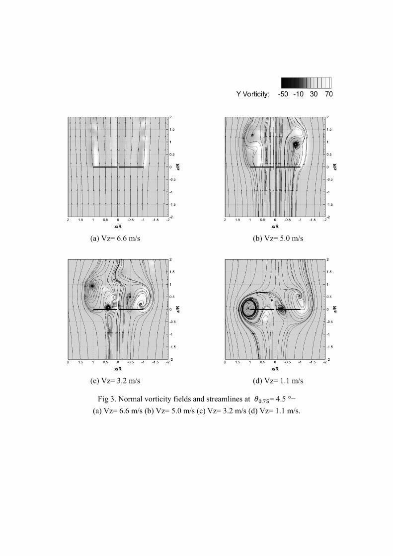
The normal vorticity fields perpendicular to the Y axis as descent velocity are can be seen cases in
Figure 3. Figure 3 shows that for WBS, smooth slipstreams are can be seen clearly. For TWS, the
generation of the tip vortices can be seen. The envelope of the swirly areas begins to be located
above the rotor disk plane. We can also notice the presence of an area of high amplitude of vorticity
at the root of blade. It is linked with the high level of local thrust. For VRS, the tip vortices are
clustered at the tip of blades. The envelopes of the recirculation zones become larger and are now
largerly located at the rotor disk plane. Hence, validation shows that VLM can predicts well the
numerical value as well as the flow-field of turbulent wake state and vortex ring state.
3.2 Simulation for floating wind turbines
The well-known NREL offshore five mega-watt wind turbine [10] was chosen, and to focus on
the aerodynamics of floating wind turbine, prescribed simple harmonic platform pitch angle was
used. The pitch amplitude is three meter, and period is twelve second, which is similar to barge
platform’s pitching motion. The simulation of operating condition is four point five meter per
second and rpm is seven point six. This is low wind speed condition which is known as highly
unsteady aerodynamics is occurred.
First, to verify the outbreak of unsteady flow in the floating wind turbine at low wind speed
condition, we compared the flow-field of fixed wind turbine’ and floating wind turbine. In the
figure 5 (a), the fixed turbine shows slipstream flow at low wind speed condition. But in the figure 5
(b), floating wind turbine shows the unsteady flow field like turbulent wake state. This is because
the net convection of growing tip vortex becomes low since periodic disturbances are added by
floating platform motion. Hence, we could verify the occurrence of unsteady flow in the floating
wind turbine. At next, we examine the cause of turbulent wake state. According to previous research,
the unsteady flow arises from platform pitching motion at downward direction. At this movement,
the induction factor, which is induced velocity divided by inflow velocity, is higher than zero point
five. Typically, it means high thrust coefficient and unsteady flow. The induction factor is very high
at the top of the rotor plane of location three in figure 6. We could know the possibility of cause of
turbulent wake state. At next, we investigated the sectional thrust at each location of floating wind
turbine if the high induction factor causes high loading. As can be seen in figure 7, different from
the expectation, we could found that the sectional thrust is the least at location three. And, at the
location seven, the sectional thrust is the most although axial induction factor is lower than location
3’s. This is because the relative wind at the rotor is very small due to backward pitching motion/ at
the location three. In other worlds, even though the induction factor cause high thrust coefficient,
thrust is low since the dynamic pressure is very low at the location three. Hence, we inspected the
location seven at the next.
Figure 8 shows the normal vorticity contour and streamlines at the location 7. At the top of the
rotor, the recirculating flow can be seen. This is because the relative velocity of the top of the blade
is high due to platform upward pitching motion, and rpm is increasing to earn more power, this
serves as increasing of tip speed ratio. In high TSR, clustering of tip vortex are growing since the
convection of tip vortex is low. Therefore, different from previous research, it shows that the
complex flow occur at upward platform pitching motion.
4. CONCLUSION
In this paper, we have investigates flows states of floating wind turbine in platform pitching
motion using numerical method, vortex lattice method. In validation case, it shows that VLM can
predict well the numerical value as well as the flow-field of turbulent wake state and vortex ring
state. In simulation of floating wind turbine, we could figure out that TWS are occurred when
floating wind turbine is operated in low speed inflow condition. Also, as different from previous
research, it has been shown that TWS is encountered when floating platform is pitching at upwind
direction. In particular, the work presented here suggests that convection of tip vortex play an
important role in governing of the behavior of the rotor in the TWS.
5. ACKNOWLEDGEMENT
This work was supported by the Human Resources Development program (No.
20104010100490) of the Korea Institute of Energy Technology Evaluation and Planning (KETEP)
grant funded by the Korea government Ministry of Knowledge Economy.

6. REFERENCES
[1] Musial, W., Butterfield, S., and Boone, A., Feasibility of floating platform systems for wind
turbines, 42nd AIAA Aerospace Sciences Meeting and Exhibit 2004; pp.476-486
[2] Sebastian, T., Lackner, M. A., Offshore Floating Wind Turbines: An Aerodynamic Perspective,
49th AIAA Aerospace Sciences Meeting, 2011
[3] Denny, V. E., Mills, A. F., Non similar solutions for laminar film condensation on a vertical
surface, Int. J. Heat Mass Transfer 1969; 12: 965-979.
[4] Suzuki, A., Application of Dynamic Inflow Theory to Wind Turbine Rotors, Doctoral
dissertation, University of Utah, 2000.
[5] Katz, J., Plotkin, A., Low-speed aerodynamics, Cambridge, UK; New York: Cambridge
University Press; 2001
[6] Kim, H., Lee, S., Son, E., Lee, S., Lee, S., Aerodynamic noise analysis of large horizontal axis
wind turbines considering fluid–structure interaction, Renewable Energy 2012; 42: 46-53.
[7] Du, Z, Selig, M. S., A 3-D stall-delay model for horizontal axis wind turbine performance
prediction, ASME Wind Energy Symposium, Reno, NV; UNITED STATES; 1998. pp. 9-19
[8] Washizu, K., Azuma, A., Experiments on a model helicopter rotor operating in the vortex ring
state, J. Aircraft 1996; 3(3): 225-230
[9] Shendahl, R., E., Klimas, P., C., Aerodynamic characteristics of seven symmetrical airfoil
sections through 180-degree angle of attack for use in aerodynamic analysis of vertical axis wind
turbines, Technical Report, SAND80-2114, SANDIA Laboratories; March 1981.
[10] Jonkman, J. Butterfield, S. Musial, W. Scott, G., Definition of a 5-MW Reference Wind
Turbine for Offshore System Development, Technical Report, NREL/TP-500-38060, National
Renewable Energy Laboratory (NREL), 2009
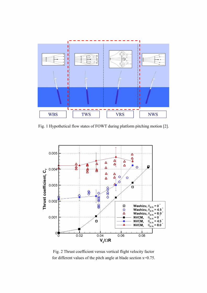
Fig. 1 Hypothetical flow states of FOWT during platform pitching motion [2].
Fig. 2 Thrust coefficient versus vertical flight velocity factor
for different values of the pitch angle at blade section x=0.75.
ㅁㅁㅁ
(a) Vz= 6.6 m/s (b) Vz= 5.0 m/s
(c) Vz= 3.2 m/s (d) Vz= 1.1 m/s
Fig 3. Normal vorticity fields and streamlines at . = 4.5 °−
(a) Vz= 6.6 m/s (b) Vz= 5.0 m/s (c) Vz= 3.2 m/s (d) Vz= 1.1 m/s.
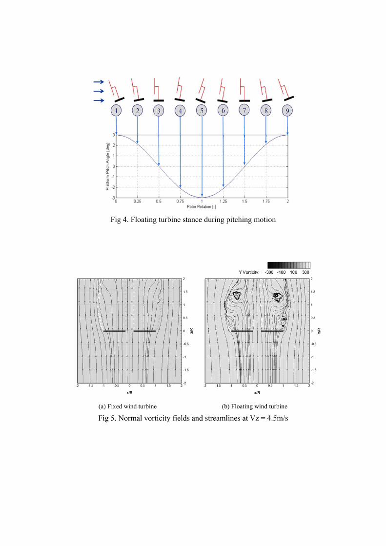
Fig 4. Floating turbine stance during pitching motion
(a) Fixed wind turbine (b) Floating wind turbine
Fig 5. Normal vorticity fields and streamlines at Vz = 4.5m/s

Fig 6. Local induction factor at each platform pitching location
Fig 7. Local induction factor at each platform pitching location
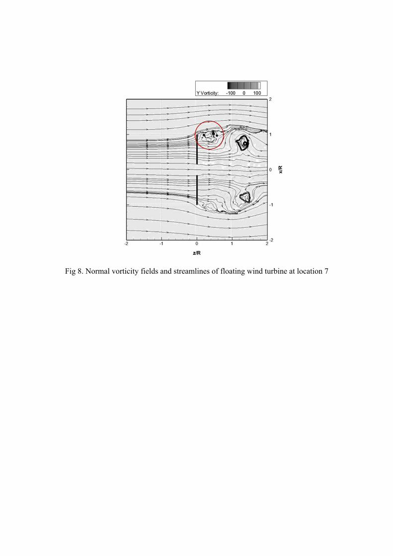
Fig 8. Normal vorticity fields and streamlines of floating wind turbine at location 7
Top Related