


Languages
Pages
Legal


promoting access to White Rose research papers
White Rose Research Online [email protected]
Universities of Leeds, Sheffield and York http://eprints.whiterose.ac.uk/
This is a copy of the final published version of a paper published via gold open access in International Journal of Rock Mechanics and Mining Sciences.
This open access article is distributed under the terms of the Creative Commons Attribution Licence (http://creativecommons.org/licenses/by/3.0), which permits unrestricted use, distribution, and reproduction in any medium, provided the original work is properly cited. White Rose Research Online URL for this paper: http://eprints.whiterose.ac.uk/80460
Published paper
Babiker, A.F.A., Smith, C.C., Gilbert, M. and Ashby, J.P. (2014) Non-associative limit analysis of the toppling-sliding failure of rock slopes. International Journal of Rock Mechanics and Mining Sciences, 71. 1 - 11. Doi: 10.1016/j.ijrmms.2014.06.008

Non-associative limit analysis of the toppling-sliding failureof rock slopes
Ahmed Faysal A. Babiker a, Colin C. Smith a,n, Matthew Gilbert a, John P. Ashby b
a Department of Civil & Structural Engineering, University of Sheffield, Mappin Street, Sheffield S1 3JD, UKb Ashby Consultants Limited, 1/26 Bassett Road, Auckland 1050, New Zealand
a r t i c l e i n f o
Article history:Received 23 February 2013Received in revised form4 March 2014Accepted 22 June 2014
Keywords:Rock slope stabilityToppling-slidingNon-associative frictionPlasticityLimit analysis
a b s t r a c t
Limit analysis is a powerful procedure which is widely used in geotechnical engineering for the analysisof collapse states. However, when applied to toppling-sliding failures in rock slopes, overestimates ofstability can arise, and hence limit equilibrium and DEM approaches have proved more popular. In thispaper it is shown that limit analysis tends to overestimate stability due to the presence of potentiallyunrealistic dilatancy at the joints. To address this, a modified plastic limit analysis procedure incorpo-rating a non-associative, low dilation, friction model is proposed. Originally developed to assess thestability of masonry walls, the procedure is here extended to allow an envelope of potential solutions tobe obtained. The numerical results obtained are found to closely match both analytical and experimentalresults from the literature, demonstrating the significant promise of the procedure.& 2014 The Authors. Published by Elsevier Ltd. This is an open access article under the CC BY license
(http://creativecommons.org/licenses/by/3.0/).
1. Introduction
1.1. Background
The influence of geological discontinuities on the stability ofrock slopes and in particular on their modes of failure had beenrecognised by a number of workers by the 1960s, as documentedin the literature, e.g. Hoek and Bray [1]. Examples of rock slopefailure modes are shown in Fig. 1, and include planar 2-dimensional wedge, 3-dimensional wedge and circular failuremodes. Plane failures occur by sliding on a single discontinuity,whereas wedge failures require two or more intersecting disconti-nuities. Although circular arc failures were originally recognised insoil slopes, they can occur in large scale rock slopes where thediscontinuities are closely spaced, or where the intervening rock issufficiently weak to fail internally.
Toppling failure involves rotation of jointed columns aboutpivot points. Pure toppling failure only occurs in very steep oroverhanging slopes. On the other hand, toppling-sliding failure canoccur in flatter slopes or in larger scale slopes, where topplingcolumns force the rock near the toe of the slope to fail by slidingor shearing through intact material. The resulting failure surfaceis often approximately circular in shape. Studies of toppling-sliding failure were initiated in the late 1960s and early 1970susing physical models, e.g. Ashby [2]. Subsequently various workers
have identified the toppling-sliding mechanism in failures observedin the field [3].
1.2. Toppling-sliding stability analysis
Various numerical and analytical procedures have been pro-posed to solve problems involving toppling-sliding failure of rockslopes. Considering numerical procedures first, the distinct ele-ment method (DEM) originally developed by Cundall [4] has beenapplied by workers such as Ashby [2], Ishida et al. [5] and Lanaroet al. [6]. With DEM large displacements and separation of blockscan be modelled by incrementally solving equations of motion,using an explicit finite-difference method that requires small timesteps. Corners of blocks are rounded to model crushing, therebyeliminating singularities. In order to balance the kinetic energy inthe system a damping coefficient is introduced, tailored accordingto block size.
Considering analytical procedures, analysis of rock slope stabi-lity is usually undertaken by a combination of kinematic analysisand limit equilibrium analysis. Kinematic analysis involves inter-preting the geometry of the geological discontinuities and theslope to determine whether failure by a given mechanism isfeasible. The rock slope stability analysis is then carried out usinga limit equilibrium analysis of the given geometry as shown bye.g. Goodman and Bray [7] and Hoek and Bray [1]. However in alimit equilibrium analysis the goal is to ensure global equilibriumis satisfied, regardless of kinematic considerations, i.e. the failuremechanism identified need not actually be kinematically admis-sible. Since then, in the absence of other readily available tools,
Contents lists available at ScienceDirect
journal homepage: www.elsevier.com/locate/ijrmms
International Journal ofRock Mechanics & Mining Sciences
http://dx.doi.org/10.1016/j.ijrmms.2014.06.0081365-1609/& 2014 The Authors. Published by Elsevier Ltd. This is an open access article under the CC BY license (http://creativecommons.org/licenses/by/3.0/).
n Corresponding author. Tel.: þ44 114 2225717.E-mail address: [email protected] (C.C. Smith).
International Journal of Rock Mechanics & Mining Sciences 71 (2014) 1–11

limit equilibrium procedures have been favoured by most workersin the field, e.g. Wyllie [8], Zanbak [9], Aydan and Kawamoto [10],Adhikary et al. [11], and Sagaseta et al. [12].
In recent years, research on rock slope stability has continued.Many researchers have continued to focus on toppling-slidingfailures, e.g. Liu et al. [13], Tatone and Grasselli [14], and Liu et al.[15], with limit equilibrium methods generally used to obtainsolutions. Additionally, some researchers have considered ‘flexuraltoppling’ scenarios, in which flexural cracking of blocks is con-sidered (e.g., [16–18]) or ‘block-flexure’ toppling, in which over-turning of some blocks is accompanied by flexural cracking ofothers (e.g. [19]). In this paper, the focus will be on modellingtoppling-sliding failures, without flexural cracking, though nowutilising a numerical approach based on the principles of limitanalysis rather than limit equilibrium, which has been the pre-dominant methodology used in this field to date.
1.3. Limit analysis
In limit analysis (see e.g. [20]) both global equilibrium andkinematic admissibility are enforced, potentially leading to morerigorous solutions when compared to limit equilibrium methodswhich generally consider equilibrium only and often requireadditional assumptions about forces acting in the system. Theonly issue is that in conventional limit analysis the relationshipbetween inter-block forces and displacements is governed by theassociative flow rule, which means that sliding along a joint will beaccompanied by separation, or ‘dilatancy’ [21]. Thus a tangentialdisplacement δt along a joint will be accompanied by a normaldisplacement δn, according to the following equation:
δn ¼ δt tan ψ ; ð1Þwhere ψ is the angle of dilatancy. This will equal the angle offriction ϕ when using a conventional limit analysis approach dueto the normality principle, leading to what is termed ‘associativefriction’. This theoretical principle makes the analysis of theproblem relatively straightforward by eliminating a source of staticindeterminacy and allows the application of the powerful upperand lower bound theorems of plasticity. However, little or nodilation is typically observed in practice (i.e. Fig. 2b vs. 2a). Whilethis does not tend to affect analysis of sliding failures due to thesimple mechanics and kinematics involved, analysis of toppling-sliding failure is complicated by the indeterminacy that affects thelocation of the points of contact between blocks and the forces atthose points. This can lead to a conventional limit analysis over-estimating the actual stability of rock slopes, given that thesegenerally comprise tightly packed assemblages of blocks.
However, since the essential features of a limit analysis approachare otherwise attractive, here a method of modelling problems witha reduced, more realistic, level of dilation within a limit analysisframework is explored, leading to a novel non-associative friction(i.e. ψaϕ) analysis.
1.4. Aims
The aims of this paper are to:
(i) Provide details of a general purpose method that can generatekinematically viable non-associative collapse mechanisms forsliding, toppling, or combined toppling-sliding, failures.
(ii) Establish the range of non-associative collapse loads relevantto a particular collapse mechanism.
(iii) Validate the proposed methodology using theoretical andexperimental results available in the literature.
An algorithm previously applied to assemblages of masonryblocks [22] will be used to address (i), while a new numericalprocedure will be presented to address (ii). Given the stronglynon-associative character of toppling-sliding rock slope failures,examples of experimental data were chosen from the rock mech-anics literature to address (iii).
Fig. 1. Modes of failure in rock slopes (after Hoek and Bray [1]). (a) Plane, (b) wedge, (c) circular and (d) toppling -sliding.
Fig. 2. Sliding along a joint: (a) with dilation (‘associative friction’ when ψ¼ϕ),(b) no dilation (‘non-associative friction’, unless ϕ¼0).
A.F.A. Babiker et al. / International Journal of Rock Mechanics & Mining Sciences 71 (2014) 1–112

2. Analysis of simple systems
2.1. Single block failure
For single blocks of the sort shown in Fig. 3, the conditions forfailure can involve sliding or toppling, and limit equilibrium andlimit analysis approaches will be identical. Sliding occurs when thetangential component of the weight ðW sin αÞ is greater than theshear resistance at the base ðμW cos αÞ, where W is the weightof the block, α is the dip angle and μ¼ tan ϕ is the frictioncoefficient. Sliding will thus occur when α4ϕ. Toppling, on theother hand, involves a column rotating about a pivot point or‘hinge’, taken to be at the lowest corner point if the block isassumed to be rigid, represented by point O in Fig. 3. Stabilityrequires that the weight W acts through a point on the line ofcontact between the base and the block. The large block in Fig. 3could thus fail by toppling, while both blocks may fail by slidingif α4ϕ.
Stability may also be assessed in a more general way byperturbing the system by some means to initiate collapse. Physicalexperiments are typically performed using a tilting table. In thisapproach failure is identified by the tilt angle (α) at which collapseoccurs. As the tilt angle of the base is increased, the horizontalcomponents of the weight driving sliding or rotation increase.This is analogous to applying an increasing horizontal body force,achieved in practice by applying a horizontal force equal inmagnitude to the self weight of each block multiplied by a loadfactor, λ. The tilt angle can then be obtained from the followingrelation:
tan α¼ λWW
ð2Þ
And hence:
α¼ tan �1 λ ð3ÞIt should be noted that in the equivalent tilted analysis, gravity
has also increased by a factor offfiffiffiffiffiffiffiffiffiffiffiffiffi1þλ2
q. However, this does not
affect the limiting tilt angle for a purely frictional problem.
2.2. Effect of associativity on the solution
For a single block, the flow rule has no effect on the solution(i.e. the amount of dilatancy which occurs does not affect the
answer). Therefore a standard limit analysis is sufficient to assessstability. However, in general, a problem will not be composed of asingle block or column but an assemblage of blocks that may slideand/or topple, and will in general interact with each other ina statically indeterminate way. It is possible to analyse suchproblems using limit analysis, but this is likely to provide a non-conservative estimate of stability when the number of blocksincreases. It is therefore necessary to take the kinematics of theproblem into consideration and in particular the effects of non-associativity.
As mentioned earlier, imposing an associative flow rule resultsin restrictive mechanisms that may result in non-conservativecollapse loads. Non-associative friction removes these kinematicrestrictions by allowing sliding with reduced dilation. This leadsto equilibrium systems with greater degrees of freedom due tofewer joints between blocks undergoing relative movement (andthus being constrained to be at yield). This can be illustratedby examining a simple two-block system, presented in the nextsection.
2.3. Two-block failure: sliding and toppling
For the two-block system shown in Fig. 4, toppling failure canoccur when the larger of the two blocks rotates while the smallerblock slides. In this problem it will be shown that the frictionalresistance at the point of contact (X) between the two blocksgoverns the range and value of the load factor λ. For the associativecase, shown in Fig. 4a, the shear force acting on the large blockat X is mobilised in the vertically upwards direction due tokinematic considerations. However, for the non-associative caseshown in Fig. 4b, since there is no relative movement (assuming
Fig. 3. Sliding and toppling: forces acting on a single block.
Fig. 4. Two-block failure: the influence of dilation (δ) on stability (assuming smalldisplacement theory holds). (a) Associative mechanism: shear force at X in thepositive vertical direction and (b) non-associative mechanism: shear force at X mayact upwards or downwards.
A.F.A. Babiker et al. / International Journal of Rock Mechanics & Mining Sciences 71 (2014) 1–11 3

instantaneous displacements and zero dilation), the force magni-tude and direction will be bracketed but not specifically defined.
2.3.1. Analysis of a sliding and toppling two-block systemFig. 5 shows the free body diagram for the two-block system
considered in Fig. 4. By considering the equilibrium and yield ofthe two blocks, associative and non-associative solutions for thesliding of Block A and toppling of Block B can be derived.
If the unit weight of the blocks is γ, then the weight W of eachblock is given as follows:
WA ¼ γhAbA ð4Þ
WB ¼ γhBbB ð5Þ
Failure is induced by the application of a horizontal body forceλW to each block, where λ provides a measure of the tilt requiredto initiate collapse, see Eq. (3). The equilibrium and yield condi-tions for the two blocks are shown in Tables 1 and 2. Joint 3,between Block A and Block B, will mobilise a strength m, such that
T3 ¼mN3 tan ϕ ð6Þ
where �1rmr1.It is also necessary to ensure that the normal force N1 acts
within the width of the base of Block A, i.e:
0rxrbA ð7Þ
In order to formulate the problem λ must be defined as afunction of T1;N1; T2;N2; T3;N3. Substituting the vertical equili-brium equation for Block A and sliding yield equation for Joint1 into the horizontal equilibrium equation for Block A and
rearranging gives
N3 ¼ ðWAþT3Þ tan ϕ�λWA ð8ÞSubstituting the horizontal and moment equilibrium equations
of Block B into Eq. (8) and rearranging gives
T3 ¼1
tan ϕλðWAþWBÞ�
WBbBhB
� ��WA ð9Þ
The mobilised strength m¼ T3=ðN3 tanϕÞ on the joint betweenthe blocks can be determined for various values of λ. For eachsolution it must be checked that T2r N2 tan ϕ and 0oxobA aresatisfied. The minimum non-associative solution is found whenm¼�1 whilst the maximum is found when m¼1.
The influence of the angle of friction on the associative loadand the minimum non-associative load is shown in Fig. 6 for thecase of a 1�1 (height�width) Block A and a 2�1 Block B.
For ϕ¼361 the associative solution can be shown to be λ¼0.6165, while the minimum non-associative solution can be shownto be λ¼0.5559, a difference of 9%, with possible non-associativesolutions λNA bracketed as follows: 0:5559r λNAr0:6165. It willbe shown later that the difference between the non-associativeand associative results will in general increase as the numberof blocks increases. It is therefore important to model non-associative friction for these types of problem.
3. Identification of non-associative collapse mechanisms
Basic limit analysis formulations for problems involving assem-blages of rigid blocks with associative frictional joints have beenconsidered by workers such as Livesley [23] and Gilbert andMelbourne [24]. In the current approach the problem consideredinvolves an assemblage of rigid blocks separated by joints whichcannot resist tensile forces. Each block may rock and/or sliderelative to an adjacent block. Each block has three degrees of
Fig. 5. Two-block failure: free body diagrams.
Table 1Two block failure: block equilibrium conditions.
Condition Block A Block B
Horizontal T1 ¼ λWAþN3 N3þT2 ¼ λWB
Vertical N1 ¼WAþT3 N2þT3 ¼WB
Moment T1hA
2þN3hA
2þN1 x�bA
2
� �¼ T3bA
2T2hB
2¼N2
bB2
� �þT3
bB2
� �
‘ x¼ ðT3þN1ÞbA�ðT1þN3ÞhA
2N1
‘ T2hB ¼WBbB
Table 2Two block failure: joint sliding yield conditions.
Condition Joint 1 Joint 2 Joint 3
Sliding T1 ¼N1 tan ϕ T2rN2 tan ϕ �N3 tanϕrT3rN3 tan ϕ
A.F.A. Babiker et al. / International Journal of Rock Mechanics & Mining Sciences 71 (2014) 1–114

freedom around its centroid: horizontal displacement, verticaldisplacement and rotation. Correspondingly three forces act alongthe joints between blocks: shear force, normal force and moment,as shown in Fig. 7. Yield conditions govern the failure criterionalong each joint i between blocks for both slip and rotation. Fig. 8aand b shows a typical failure surfaces for toppling and sliding atany contact i. It can be seen that both criteria depend on thenormal force which is the unknown parameter in these type ofproblems. When a classical equilibrium formulation is employed,this involves maximising a load factor while ensuring that eachblock is in equilibrium and that yield is not violated at any joint.Considering an assemblage of b blocks and c joints, this problemcan be formulated as a linear programming (LP) problem asfollows:
max λ
subject to
Bq�λfL ¼ fD ð10Þ
mir0:5nihimiZ�0:5nihisirμini
siZ�μini
9>>>>>=>>>>>;
for each joint between blocks i¼ 1;…; c ð11Þ
where λ is the load factor, B is a suitable ð3b� 3cÞ equilibriummatrix, enforcing horizontal, vertical and moment equilibrium,and q and f are respectively vectors of joint forces and block loads.Thus qT ¼ n1; s1;m1;n2; s2;m2::nc; sc;mcf g; f ¼ fDþλfL where fD and
fL are respectively vectors of dead and live loads. Joint and blockforces, dimensions and frictional properties are shown in Fig. 7.Using this formulation the LP variables are the contact forces forany joint i, i.e: ni; si;mi (where niZ0; si;mi are free variables).Eq. (11) enforces joint yield conditions for each joint in the n-s-mdomain and defines the failure criteria governed both by slidingand toppling. Note that although the associative flow rule is notexplicitly referred to in this formulation, it is implicitly enforced(e.g. see [23]).
More recently, extended formulations which allow non-associ-ative frictional joints to be treated have been proposed by workerssuch as Ferris and Tin-Loi [25], Orduña and Lourenco [26] andGilbert et al. [22]. Here the latter approach is used as astarting point.
3.1. Limit analysis formulation for discrete block rotation and sliding(after Gilbert et al. [22])
In essence the approach proposed by [22] involves the succes-sive solution of simple associative problems. Thus, referring toFig. 9a, consider a point A representing the forces acting on a jointbetween blocks and lying on the Mohr–Coulomb failure surface(indicated by the solid line), where the normal and shear forcesare N and T respectively. The associated flow rule clearly requiresψ¼ϕ (i.e. flow in the direction of the solid arrow), whereas therequired non-associated flow, with ψ¼0, will be in the directionindicated by the dashed arrow. In order to ensure ψ¼0, while stillutilising an associative analysis, a fictitious failure surface can beconstructed by rotating the yield surface about the force point
Fig. 6. The influence of friction angle (ϕ) on the associative and minimum non-associative load factor λ for the two block problem.
Fig. 7. Block j geometry and properties, and contact forces for joint i.
A.F.A. Babiker et al. / International Journal of Rock Mechanics & Mining Sciences 71 (2014) 1–11 5
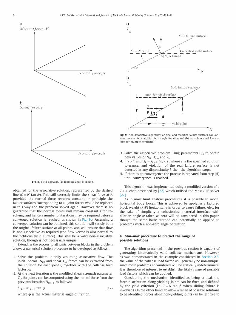
obtained for the associative solution, represented by the dashedline ðC ¼N tan ϕÞ. This still correctly limits the shear force at Aprovided the normal force remains constant. In principle thefailure surfaces corresponding to all joint forces would be replacedin this way and the problem solved again. However there is noguarantee that the normal forces will remain constant after re-solving, and hence a number of iterations may be required before aconverged solution is reached, as shown in Fig. 9b. Assuming aconverged solution can be obtained, this solution will satisfy boththe original failure surface at all points, and will ensure that flowis non-associative as required (the flow vector is also normal tothe fictitious yield surface). This will be a valid non-associativesolution, though is not necessarily unique.
Extending the process to all joints between blocks in the problemallows a numerical solution procedure to be developed as follows:
1. Solve the problem initially assuming associative flow. Theinitial normal Ni;0 and shear Ti;0 forces can be extracted fromthe solution for each joint i, together with the collapse loadfactor λ0.
2. At the next iteration k the modified shear strength parameterCi;k for joint i can be computed using the normal force from theprevious iteration Ni;k�1 as follows:
Ci;k ¼Ni;k�1 tan ϕ ð12Þwhere ϕ is the actual material angle of friction.
3. Solve the associative problem using parameters Ci;k to obtainnew values of Ni;k, Ti;k, and λk.
4. If k41 and ∣λk � λk�1∣=λkoϵ, where ϵ is the specified solutiontolerance, and violation of the real failure surface is notdetected at any discontinuity i, then the algorithm stops.
5. If there is no convergence the process is repeated from step (ii)until convergence is reached.
This algorithm was implemented using a modified version of aCþþ code described by [22] which utilised the Mosek LP solver[27].
As in most limit analysis procedures, it is possible to modelhorizontal body forces. This is achieved by applying a factoredblock weight (λW) horizontally in order to cause failure. Also, forthe sake of simplicity a cohesionless material interface withdilation angle ψ taken as zero will be considered in this paper,though the same basic method can potentially be applied toproblems with a non-zero angle of dilation.
4. Min–max procedure to bracket the range ofpossible solutions
The algorithm presented in the previous section is capable ofgenerating kinematically valid collapse mechanisms. However,as was demonstrated in the example considered in Section 2.3,the value of the collapse load factor will generally be non-unique,since most problems encountered will be statically indeterminate.It is therefore of interest to establish the likely range of possibleload factors which can be applied.
Considering the mechanism identified as being critical, theforce distribution along yielding joints can be fixed and definedby the yield criterion (i.e. T ¼N tan ϕ when sliding failure isinvolved). On the other hand, to allow a range of possible solutionsto be identified, forces along non-yielding joints can be left free to
Fig. 8. Yield domains. (a) Toppling and (b) sliding.
Fig. 9. Non-associative algorithm: original and modified failure surfaces. (a) Con-stant normal force at joint for a single iteration and (b) variable normal force atjoint for multiple iterations.
A.F.A. Babiker et al. / International Journal of Rock Mechanics & Mining Sciences 71 (2014) 1–116
take different values subject to equilibrium being enforced, andyield not being violated. Thus the following procedure is proposed:
(i) Obtain a non-associative solution using the proceduredescribed in Section 3.
(ii) Setup a new associative analysis, but this time prescribing thatyield must occur along all joints that yielded in the mechan-ism identified in (i).
(iii) Solve the problem searching for the minimum load factor,λmin.
(iv) Solve the problem searching for the maximum load factor, λmax.
It should be noted that the initial non-associative solutionreferred to in (i) and the maximised solution found in (iv) will bothcorrespond to kinematically compatible collapse mechanisms. (N.B. although an equilibrium formulation has been used, collapsemechanisms can be identified using LP duality principles, e.g. seeCharnes et al. [28].) However, the minimised solution from (iii)will not in general correspond to a mechanism that is kinemati-cally viable, since the solution derives from a minimisationprocess. However in this case the original mechanism should becompatible with the solution found and thus remains valid.
The procedure described has been tested and found to be robust aslong as a viable mechanism is identified in step (i) of the procedure.However it may sometimes be found to be difficult to preciselydefine the form and extent of a mechanism, and whether yieldingis truly occurring in a given joint. This is particularly the case forproblems involving numerous blocks, with very small relative move-ments between some blocks. After investigating the issue further itwas found that relative displacement was actually the most reliableindicator of yielding, and a constant threshold value of 10�5 waschosen for use in the examples described in this paper.
5. Case studies
5.1. Example 1: Goodman and Bray (analytical)
The following is a limit equilibrium block-toppling problembased on an example proposed by Goodman and Bray [7],published by Hoek and Bray [1] and reprinted by Wyllie and
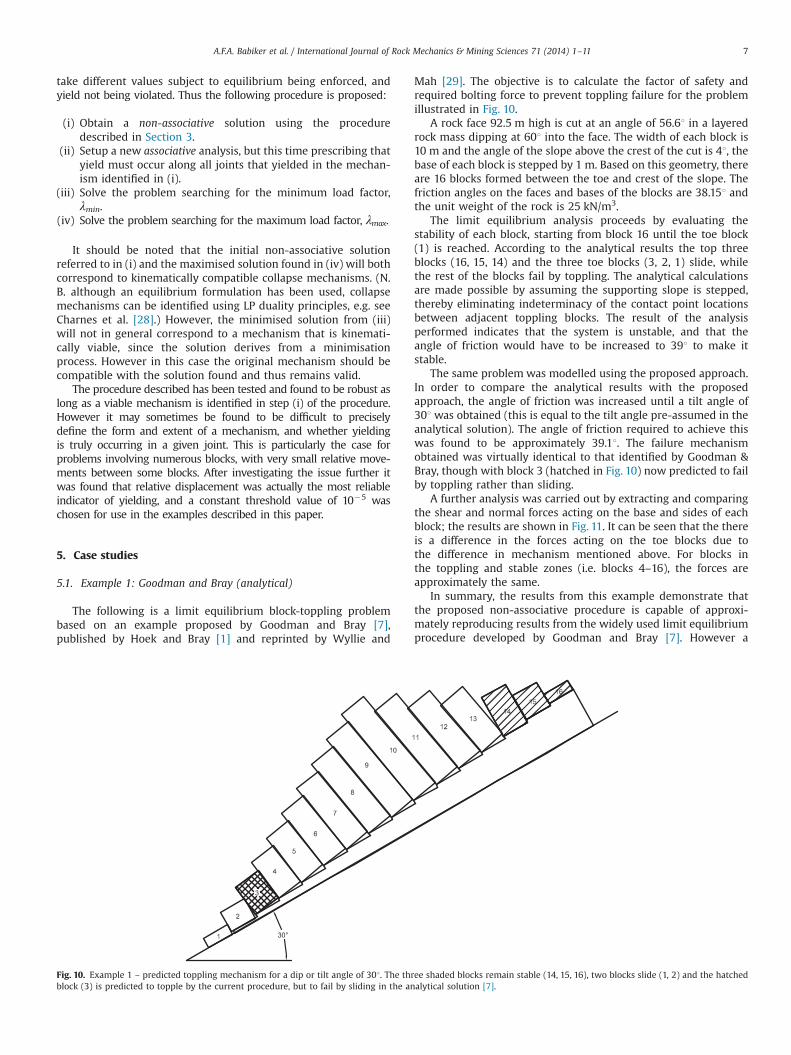
Mah [29]. The objective is to calculate the factor of safety andrequired bolting force to prevent toppling failure for the problemillustrated in Fig. 10.
A rock face 92.5 m high is cut at an angle of 56.61 in a layeredrock mass dipping at 601 into the face. The width of each block is10 m and the angle of the slope above the crest of the cut is 41, thebase of each block is stepped by 1 m. Based on this geometry, thereare 16 blocks formed between the toe and crest of the slope. Thefriction angles on the faces and bases of the blocks are 38.151 andthe unit weight of the rock is 25 kN/m3.
The limit equilibrium analysis proceeds by evaluating thestability of each block, starting from block 16 until the toe block(1) is reached. According to the analytical results the top threeblocks (16, 15, 14) and the three toe blocks (3, 2, 1) slide, whilethe rest of the blocks fail by toppling. The analytical calculationsare made possible by assuming the supporting slope is stepped,thereby eliminating indeterminacy of the contact point locationsbetween adjacent toppling blocks. The result of the analysisperformed indicates that the system is unstable, and that theangle of friction would have to be increased to 391 to make itstable.
The same problem was modelled using the proposed approach.In order to compare the analytical results with the proposedapproach, the angle of friction was increased until a tilt angle of301 was obtained (this is equal to the tilt angle pre-assumed in theanalytical solution). The angle of friction required to achieve thiswas found to be approximately 39.11. The failure mechanismobtained was virtually identical to that identified by Goodman &Bray, though with block 3 (hatched in Fig. 10) now predicted to failby toppling rather than sliding.
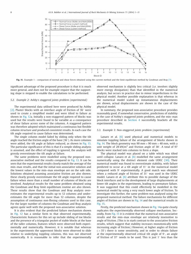
A further analysis was carried out by extracting and comparingthe shear and normal forces acting on the base and sides of eachblock; the results are shown in Fig. 11. It can be seen that the thereis a difference in the forces acting on the toe blocks due tothe difference in mechanism mentioned above. For blocks inthe toppling and stable zones (i.e. blocks 4–16), the forces areapproximately the same.
In summary, the results from this example demonstrate thatthe proposed non-associative procedure is capable of approxi-mately reproducing results from the widely used limit equilibriumprocedure developed by Goodman and Bray [7]. However a
Fig. 10. Example 1 – predicted toppling mechanism for a dip or tilt angle of 301. The three shaded blocks remain stable (14, 15, 16), two blocks slide (1, 2) and the hatchedblock (3) is predicted to topple by the current procedure, but to fail by sliding in the analytical solution [7].
A.F.A. Babiker et al. / International Journal of Rock Mechanics & Mining Sciences 71 (2014) 1–11 7
significant advantage of the proposed procedure is that it is muchmore general, and does not for example require that the support-ing slope is stepped to enable the calculations to be performed.
5.2. Example 2: Ashby's staggered joints problem (experimental)
The experimental data utilised here were produced by Ashby[2]. Plaster blocks with an interface angle of friction of 361 wereused to create a simplified model and were tilted to failure asshown in Fig. 12a. Initially a non-staggered pattern of blocks wasused but the results were found to be variable as a consequenceof shear failure across some of the columns. A staggered patternwas therefore adopted which maintained a continuous but flexiblecolumn structure and produced consistent results. In each case thetilt angle required to cause failure was determined.
The single column model failed by sliding only when the tiltangle reached the friction angle of the base (361). As more columnswere added, the tilt angle at failure reduced, as shown in Fig. 13.The particular significance of this is that if a simple sliding analysisis assumed, and the effect of toppling is ignored, the analysis willgrossly overestimate the tilt angle at failure.
The same problems were modelled using the proposed non-associative method and the results compared in Fig. 13. It can beseen that the experimental results closely match the average of themin–max results, and that the initial non-associative solution andthe lowest values in the min–max envelope are on the safe side.Solutions obtained assuming associative friction are also shown;these clearly grossly overestimate the tilt angle required to causefailure when more than a small number of columns of blocks areinvolved. Analytical results for the same problem obtained usingthe Goodman and Bray limit equilibrium routine are also shown.These results show that the Goodman and Bray analysis over-estimates the experimental results up to 12 columns and under-estimates the tilt angle for more than 12 columns, despite theassumption of continuous non-flexing columns used in this case.For the larger number of columns the Goodman and Bray analysisagrees quite well with the proposed non-associative solution.
It is also evident that the predicted failure mechanism shownin Fig. 12 has a similar form to that observed experimentally.Characteristic features for this set up include sliding of toe blocksand the presence of a triangular pocket of stable blocks at the baseof the taller columns, features which were observed both experi-mentally and numerically. However, it is notable that whereasin the experiments the uppermost blocks were observed to sliderelative to underlying toppling columns, this was not observednumerically. It is reasonable to infer that the experimentally
observed mechanism is slightly less critical (i.e. involves slightlymore energy dissipation) than that identified in the numericalanalysis, but occurs in practice due to minor imperfections in thephysical model. Another possible explanation is that whereas inthe numerical model scaled up instantaneous displacementsare shown, actual displacements are shown in the case of thephysical model.
In summary, the proposed non-associative procedure providesreasonably good, if somewhat conservative, predictions of stabilityin the case of Ashby's staggered joints problem, and the min–maxprocedure described in Section 4 successfully brackets all theexperimental results.
5.3. Example 3: Non-staggered joints problem (experimental)
Lanaro et al. [6] used physical and numerical models tosimulate toppling failure of the arrangement of blocks shown inFig. 14. The block geometry was 90 mm�90 mm�40 mm, with aunit weight of 28 kN/m3 and friction angle of 381. A total of 97blocks were stacked into columns to form a slope.
The physical model was placed on a table which was tilteduntil collapse. Lanaro et al. [6] modelled the same arrangementnumerically using the distinct element code UDEC [30]. Theirnumerical model was found to overestimate stability, with failurepredicted to occur at a tilt angle of 111 in the numerical modelcompared with 91 experimentally. A good match was obtainedwhen a reduced angle of friction of 311 was used in the UDECmodel. Lanaro et al. [6] attribute this to possible damage of theblock interfaces and to the development of large displacements atlower tilt angles in the experiments, leading to premature failure.It was suggested that this could effectively be modelled in thenumerical model by using a very much lower angle of friction. Toinvestigate this further, the same problem was analysed using theproposed numerical method. The failure mechanisms for differentangles of friction are shown in Fig. 14 and the numerical results inFig. 15.
Firstly, the predicted mechanism shown in Fig. 14a quite closelyreplicates the experimentally observed collapse mechanism. Sec-ondly, from Fig. 15 it is evident that the numerical non-associativeresults and the min–max envelope are relatively insensitive toangle of friction. (This is in stark contrast to the associative frictionresults, which suggest that stability increases monotonically withincreasing angle of friction.) However, at higher angles of frictionð4351Þ there is some sensitivity, and in order to obtain failureat the experimentally observed critical tilt angle of 91, an angleof friction of 371 needs to be used. This is just 11 less than the
Fig. 11. Example 1 – comparison of normal and shear forces obtained using the current method and the limit equilibrium method by Goodman and Bray [7].
A.F.A. Babiker et al. / International Journal of Rock Mechanics & Mining Sciences 71 (2014) 1–118
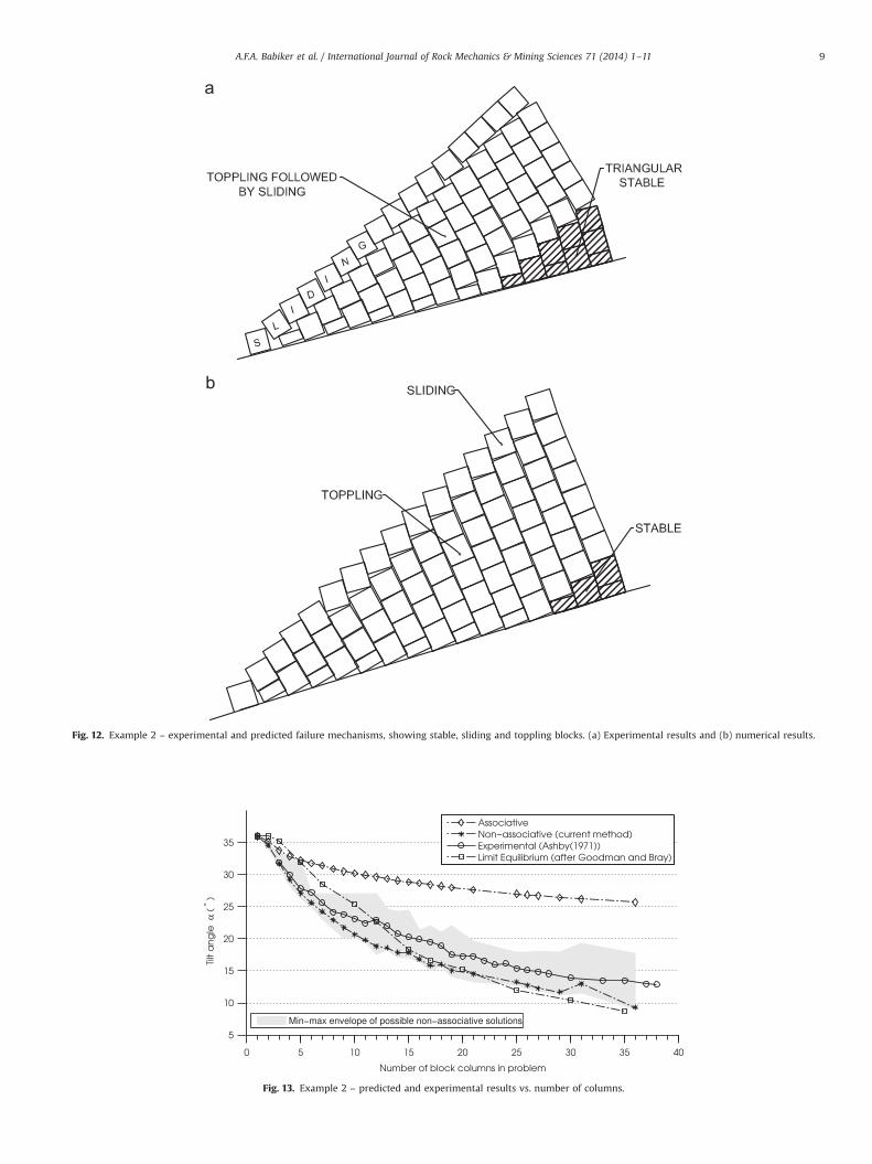
Fig. 12. Example 2 – experimental and predicted failure mechanisms, showing stable, sliding and toppling blocks. (a) Experimental results and (b) numerical results.
Fig. 13. Example 2 – predicted and experimental results vs. number of columns.
A.F.A. Babiker et al. / International Journal of Rock Mechanics & Mining Sciences 71 (2014) 1–11 9

measured friction, but is significantly higher than the angle offriction required in the UDEC model to replicate the experimentalresults (311).
In summary, the proposed non-associative procedure providesreasonably good predictions of stability for the model studied byLanaro et al., with the min–max procedure described in Section 4bracketing the experimental result over a wide range of angles offriction ð311rϕ1r371Þ.
5.4. Discussion
The proposed method of generating non-associative mechan-isms has been found to be capable of generating credible mechan-isms very similar to those seen experimentally. However, whilstthere may be several viable non-associative mechanisms, thestandard procedure will only converge on one solution (assumingthat this can be obtained; note that several solutions are missing
from Fig. 13 because the prescribed convergence tolerance could insome cases not be met). While the converged solution is notguaranteed to be the least stable mechanism, the results obtainedso far indicate that the mechanism found is generally as, or more,critical than that observed in the corresponding physical model.This is not necessarily surprising as it is likely that the physicalmodels will have minor discrepancies from the idealised numer-ical model geometry, that influence the nature of the mechanismthat actually forms.
Finally, although in the interests of space associative frictionmechanisms have not been shown in the paper, these weregenerally observed to be highly unrealistic. Even more impor-tantly, the associative friction model has been found to be prone togrossly over-predicting the critical tilt angles in the case of theexperimental examples considered (e.g. 25.71 cf. a non-associativeprediction of 9.31 in the case of the Ashby staggered block exampleinvolving 36 columns).
Fig. 14. Example 3 – range of predicted failure mechanisms (shaded blocks are stable). (a) ϕ¼311–351, (b) ϕ¼361, and (c) ϕ¼381.
Fig. 15. Non-staggered joints problem: numerical results compared to experimental results.
A.F.A. Babiker et al. / International Journal of Rock Mechanics & Mining Sciences 71 (2014) 1–1110
6. Conclusions
1. A numerical analysis procedure originally developed to assessthe stability of masonry walls has been shown to be capable ofgenerating kinematically viable non-associative solutions forrock toppling problems, similar or identical to those observedexperimentally, or obtained using conventional limit-equilibriumtechniques in the case of simple problems.
2. A significant advantage of the proposed limit analysis proce-dure compared with the limit equilibrium techniques that havebeen traditionally applied to rock toppling problems is that it isgenerally applicable, and does not require assumptions to bemade about how forces act within the system.
3. The numerical analysis procedure has been found to providereasonable, albeit somewhat conservative (i.e. safe), estimatesof the stability of experimental rock toppling setups consideredin the literature.
4. A new min–max procedure that can provide minimum andmaximum non-associative solutions for a particular kinematiccollapse mechanism has been described. When used in combi-nation with the proposed non-associative numerical analysisprocedure this generates solutions that successfully bracketexperimental data described in the literature.
5. Conventional associative friction limit analysis models arelikely to grossly over-predict the stability of rock slopes whentoppling of blocks is involved, and their use should therefore beavoided.
Acknowledgments
The first author was supported by an EPSRC DTA studentship.The support of EPSRC funding under grant reference EP/I014489/1is also gratefully acknowledged.
References
[1] Hoek E, Bray JW. Rock slope engineering. 2nd ed. . London: The Institution ofMining and Metallurgy; 1977.
[2] Ashby J. Sliding and toppling modes of failure in models and jointed rockslopes [M.Sc. thesis]. Department of Mining, Imperial College of Science &Technology, London, UK; 1971.
[3] De Freitas MH, Waters RJ. Some field examples of toppling failure. Geotechni-que 1973;23(4):495–514.
[4] Cundall PA. A computer model for simulating progressive large scale move-ments in blocky rock systems. In: Proceedings of the symposium of Interna-tional Society of Rock Mechanics. vol. 1. Nancy, France; 1971, p. 129–70.
[5] Ishida T, Chigira M, Hibino S. Application of the distinct element method foranalysis of toppling observed on a fissured rock slope. Rock Mech Rock Eng1987;20:277–83.
[6] Lanaro F, Jing L, Stephansson O, Barla G. D.E.M. modelling of laboratory tests ofblock toppling. Int J Rock Mech Min. Sci 1997;34(3–4):173.e1–15.
[7] Goodman RE, Bray JW. Toppling of rock slopes. In: ASCE speciality conferenceon rock engineering for foundations and slopes, Boulder, Colorado; vol. 2.ASCE; 1976. p. 201–34.
[8] Wyllie DC. Toppling rock slope failures examples of analysis and stabilization.Rock Mech Rock Eng 1980;13:89–98.
[9] Zanbak C. Design charts for rock slopes susceptible to toppling. J Geotech EngASCE 1983;109(8):1039–62.
[10] Aydan O, Kawamoto T. The stability of slopes and underground openings againstflexural toppling and their stabilisation. Rock Mech Rock Eng 1992;25(3):143–65.
[11] Adhikary DP, Dyskin AV, Jewell RJ, Stewart DP. A study of the mechanism offlexural toppling failure of rock slopes. Rock Mech Rock Eng 1997;30(2):75–93.
[12] Sagaseta C, Sánchez JM, Cañizal J. A general analytical solution for the requiredanchor force in rock slopes with toppling failure. Int J Rock Mech Min Sci2001;38(3):421–35.
[13] Liu CH, Jaksa MB, Meyers AG. A transfer coefficient method for rock slopetoppling. Can Geotech J 2009;46(1):1–9.
[14] Tatone BSA, Grasselli G. Rocktopple: a spreadsheet-based program for prob-abilistic block-toppling analysis. Comput Geosci 2010;36(1):98–114.
[15] Liu CH, Jaksa MB, Meyers AG. Toppling mechanisms of rock slopes consideringstabilization from the underlying rock mass. Int J Rock Mech Min Sci 2010;47(2):348–54.
[16] Amini M, Majdi A, Aydan O. Stability analysis and the stabilisation of flexuraltoppling failure. Rock Mech Rock Eng 2009;42(5):751–82.
[17] Alzoubi AK, Martin CD, Cruden DM. Influence of tensile strength on topplingfailure in centrifuge tests. Int J Rock Mech Min Sci 2010;47(6):974–82.
[18] Majdi A, Amini M. Analysis of geo-structural defects in flexural topplingfailure. Int J Rock Mech Min Sci 2011;48(2):175–86.
[19] Amini M, Majdi A, Veshadi M. Stability analysis of rock slopes against block-flexure toppling failure. Rock Mech Rock Eng 2012;45(4):519–32.
[20] Chen WF. Limit analysis and soil plasticity. Developments in geotechnicalengineering. Amsterdam: Elsevier; 1975 vol. 7.
[21] Drucker DC. Coulomb friction, plasticity, and limit loads. J Appl Mech ASME1954;21(1):71–4.
[22] Gilbert M, Casapulla C, Ahmed HM. Limit analysis of masonry block structureswith non-associative frictional joints using linear programming. ComputStruct 2006;84(3):873–87.
[23] Livesley RK. Limit analysis of structures formed from rigid blocks. Int J NumerMethods Eng 1978;12(12):1853–71.
[24] Gilbert M, Melbourne C. Rigid-block analysis of masonry structures. Struct Eng1994;72:356–61.
[25] Ferris MC, Tin-Loi F. Limit analysis of frictional block assemblies as amathematical program with complementarity constraints. Int J Mech Sci2001;43:209–24.
[26] Orduña A, Lourenco PB. Cap model for limit analysis and strengthening ofMasonry structures. ASCE J Struct Eng 2003;129:1367–75.
[27] Mosek, The MOSEK optimization tools manual. Mosek ApS; version 5.0 ed.;2010. URL ⟨http://www.mosek.com⟩.
[28] Charnes A, Lemke CE, Zienkiewicz OC. Virtual work, linear programming andplastic limit analysis. Proc R Soc Lond Ser A Math Phys Sci 1959;251(264):110–6.
[29] Wyllie DC, Mah CW. Rock slope engineering: civil and mining. 4th ed. London:UK Spon Press; 2004.
[30] Cundall PA. UDEC—a generalized distinct element program for modelingjointed rock. In: U.S. Army, European Research Office, London. Peter CundallAssociates; 1980, Report PCAR-1-80, Contract DAJA37-79-C-0548.
A.F.A. Babiker et al. / International Journal of Rock Mechanics & Mining Sciences 71 (2014) 1–11 11
Top Related