


Languages
Pages
Legal

UNIVERSITÉ DU QUÉBEC À CHICOUTIMI
MÉMOIRE PRESENTE A
L'UNIVERSITÉ DU QUÉBEC À CHICOUTIMI
COMME EXIGENCE PARTIELLE
DE LA MAÎTRISE EN INFORMATIQUE
OFFERTE A
L'UNIVERSITÉ DU QUÉBEC À CHICOUTIMI
EN VERTU D'UN PROTOCOLE D'ENTENTE
AVEC L'UNIVERSITÉ DU QUÉBEC À MONTREAL
PAR
BAI HAI
THE IMPLEMENTATION OF
CRP ( CAPACITY REQUIREMENTS PLANNING) MODULE
JUIN 2009

bibliothèquePaul-Emile-Bouletj
UIUQAC
Mise en garde/Advice
Afin de rendre accessible au plusgrand nombre le résultat destravaux de recherche menés par sesétudiants gradués et dans l'esprit desrègles qui régissent le dépôt et ladiffusion des mémoires et thèsesproduits dans cette Institution,l'Université du Québec àChicoutimi (UQAC) est fière derendre accessible une versioncomplète et gratuite de cette �uvre.
Motivated by a desire to make theresults of its graduate students'research accessible to all, and inaccordance with the rulesgoverning the acceptation anddiffusion of dissertations andtheses in this Institution, theUniversité du Québec àChicoutimi (UQAC) is proud tomake a complete version of thiswork available at no cost to thereader.
L'auteur conserve néanmoins lapropriété du droit d'auteur quiprotège ce mémoire ou cette thèse.Ni le mémoire ou la thèse ni desextraits substantiels de ceux-ci nepeuvent être imprimés ou autrementreproduits sans son autorisation.
The author retains ownership of thecopyright of this dissertation orthesis. Neither the dissertation orthesis, nor substantial extracts fromit, may be printed or otherwisereproduced without the author'spermission.

ABSTRACT
ERP (Enterprise Resource Planning) was originated as a management conceptbased on the supply chain to provide a solution to balance the planning of productionwithin an enterprise. This article focuses on the CRP module in ERP, describes in detail theconcept, content and modularization of CRP as well as its usefulness and application in theproduction process. The function of CRP module is to expand orders to production processto calculate production time, then to adjust the load or accumulative load of each center ormachine accordingly. The function described in the article tries to load production timeused as load to an unlimited extend, then to use auto-balance or normal adjustment todetermine the feasibility of the production order planning.

PREFACE
I would like to thank Prof. Yu Chang Yun for letting me work on this topic
although I study computer science. I have to thank for her patience, support and many
answers to my questions.
Thanks to Mr. Zheng Gang and especially Mr. Yang Chuan Cai for their assistance
and help in realizing the implementation.
I would like to thank everyone at Tianjin ZhuRi Software Co. Ltd., for sharing
their ideas with me and helping me over the many decisions I had to make on the way.
Finally, I would like to thank all my friends and fellow graduate students here at
the University of Technology and Science of Tianjin. The assistance and encouragement
offered by them has been a great and unexpected aid in my Master's work..

TABLE OF CONTENTS
LIST OF TABLES vi
LIST OF FIGURES ix
LIST OF ABBREVIATIONS x
INTRODUCTION 12
CHAPTER 1 REVIEW THE EVOLUTION OF ERP 18
CHAPTER 2 THE REQUIREMENT ANALYSIS AND SYSTEM DESIGN 22
2.1 LOGIN FUNCTION 24
2.2 DATA INPUT FUNCTION 26
2.3 CALCULATE LOAD FUNCTION 28
2.4 AUTO-BALANCE FUNCTION 36
2.5 MANUAL ADJUST FUNCTION 45
2.6 CHECK THE FEASIBILITY OF THE PLANNING 54
2.7 OUTPUT THE NON-EXECUTABLE INFORMATION 55
2.8 DATA OUTPUT 55
2.9 LOGOUT 56
CHAPTER 3 THE CLASS DESCRIPTION 57
3.1 THE UML OF THE CRP MODULE 57
3.2 THE DATA INPUT CLASS 59

3.3 LOAD CALCULATION CLASS 61
3.4 MANUAL ADJUST CLASSES 63
3.5 CRP TASK CLASS 65
CHAPTER 4 THE IMPLEMENTATION 69
CONCLUSION 73
REFERENCES 75
APPENDIX A CLASS TABLE 77
APPENDIX B LOAD CALCULATION SOURCE CODE 80

LIST OF TABLES
Table 2.1 The following table shows the login input items 24
Table 2.2 The following table shows the login input items 25
Table 2.3 Login modes 26
Table 2.4 The input items of the data input fonction 26
Table 2.5 The output items of the data input fonction 27
Table 2.6 The input items of the calculate load fonction..................... 28
Table 2.7 The output items of the calculate load fonction 28
Table 2.8 The object to calculate load,. 29
Table 2.9 The calculation of LFT (Backward scheduling logic) 30
Table 2.10 The calculation of EST (Backward scheduling logic)................. 30
Table 2.11 The information introduced from the posterior planning (FCS) 34
Table 2.12 The information deployed from the planned order 34
Table 2.13 The input items of the Auto-balance fonction 36
Table 2.14 The output items of the Auto-balance fonction 36
Table 2.15 The operations of the manual adjust fonction. 45
Table 2.16 The input items of the transference of the load 46
Table 2.17 The output items of the transference of the load 47
Table 2.18 The information of the new work order of the division of the work order. 48

Vil
Table 2.19 The input items of the division of the work order 48
Table 2.20 The output items of the division of the work order 49
Table 2.21 The input items of the combination of the work order 50
Table 2.22 The output items of the combination of the work order 50
Table 2.23 The input items of the accession of the work order..... 51
Table 2.24 The output items of the accession of the work order........................... 51
Table 2.25 The input items of the deletion of the work order 51
Table 2.26 The output items of the deletion of the work order 52
Table 2.27 The input items of the modification of the quantity of the work order 52
Table 2.28 The output items of the modification of the quantity of the work order .... 53
Table 2.29 The operations of the modification of the shift 53
Table 2.30 The input items of the verification of the feasibility of the planning 54
Table 2.31 The output items of the verification of the feasibility of the planning 54
Table 2.32 The input items of the output of the non-executable information 55
Table 2.33 The output items of the output of the non-executable information 55
Table 2.34 The output items of the data output function 56
Table 3.1 The private variable declarations in the ZRDatalnput class 59
Table 3.2 The public function declarations in the ZRDatalnput class 60
Table 3.3 Shows the private function declarations of the ZRDatalnput class 61
Table 3.4 Shows the private variable declarations in the ZRLoadCalcul class 62
Table 3.5 The public function declarations in the ZRLoadCalcul class 62
Table 3.6 The private function declarations of the ZRLoadCalcul class. 63

Vlll
Table 3.7 The public fonctions placed in the interface ZRManualAdjust 64
Table 3.8 Shows the private variable declarations in the ZRLoadTransfer class... 64
Table 3.9 Shows the public variable declarations in the ZRLoadTransfer class.... 65
Table 3.10 Shows the private variable declarations in the ZRCRPTask class 65
Table 3.11 Shows the public variable declarations in the ZRCRPTask class 66
Table 3.12 The public fonction declarations in the ZRCRPTask class........... 66

LIST OF THE FIGURES
Figure 2.1 The workflow of the CRP module 23
Figure 2.2 The calculation of EST and LFT 31
Figure 2.3 An example of the load..... 35
Figure 2.4 ....The load of the each measure unit 38
Figure 2.5 The overload 20(Hr) is transfeired to measure unit 4.......... 39
Figure 2.6 The overload 40(Hr) is transferred to the measure unit 3 40
Figure 2.7 The overload 20(Hr) is transferred to the measure unit 1 41
Figure 2.8 The load of the each measure unit 42
Figure 2.9 The load transference until the measure unit 2 42
Figure 2.10 Transfer the entire load of working procedure B to the measure unit 1. 43
Figure 2.11 Transfer the overload to the measure unit 1 44
Figure 3.1 The UML of the classes 58
Figure 4.1 Login window of the CRP module 69
Figure 4.2 The main frame of this CRP module 70
Figure 4.3 The menu items of the manual adjust operations 71
Figure 4.4 The order transference operation 71
Figure 4.5 The graphic output of the load.... 72

LIST OF ABBREVIATIONS
Enterprise Resource Planning
Materials Requirements Planning
Capacity Requirements Planning
Finite Capacity Scheduling
Object-Oriented
Bills of Materials
Management Information Systems
Work In Progress
Master Production Schedule
Just in Time
Advanced Planning and Scheduling
Graphical User Interface
Relational Database Management System
Fourth-Generation Language
Computer-Aided Software Engineering
Supply Chain Management
Customer Relationship Management
Product Data Management
ERP
MRP
CRP
FCS
OO
BOM
MIS
WIP
MPS
JIT
APS
GUI
RDBMS
4GL
CASE
SCM
CRM
PDM

XI
Manufacturing Executions Systems MES
Latest Finish Time LFT
Earliest Start Time EST
Unified Modeling Language UML
INTRODUCTION
The CRP module discussed in this paper is the sub-module of the ERP system
ZRERP version 1.1 developed by ZhuRi Software Co., Ltd. The version 1.0 of ZRERP is
delivered at October 2000. But it did not include the CRP module. According to the user's
feedback, version 1.0 is not completely fit the requirement of the modem production. An
overused work center creates obvious problems: backup and delays, unanticipated and
costly overtime, and loss of quality due to production pressures. After analyzing the load
across work centers, complex functions analyze the MRP schedule and compare it against
the current capacity of each work center. Using these inquiries, ZRERP version 1.1 is
decided to add the CRP module. This is the motivation of my thesis.
This CRP module uses the output of the MRP system as the input data. It will deploy
the manufacturing order into the manufacturing process, then to calculate the operation
time of the process. This module can process two kinds of the plan unit for the load
calculation: work centre or work machine. The measure unit of the plan can be day or week.
When we calculate the load of the plan unit, we also use the planned orders outputted by
the posterior plan function (Finite Capacity Scheduling -FCS) with the manufacturing
orders, so that this load calculation is more accurate. After adding the load to the plan unit,
we can the auto-balance operation or the manual adjust operation to verify the feasibility of
13
the plan of the tentative orders. If the plan is feasible, the module will output the
manufacturing orders and produce the job orders. If the plan is not feasible, it will output
the useful inforaiation to the anterior fonction to review the tentative orders.
In ZRERP version 1.0, the database design is completed. In my papers, I don't care
with this issue.
Through this CRP module is the sub-module of the ZRERP system, it can also be run
independently. Following are the base knowledge and software tools used in my thesis.
1. The Development Environment
The hardware environment is:
Personal Computer with the frequency of 2G Hz, 512MB Memory, 80GB hard disk.
The Software environment is:
Windows 2K/XP, JBuilder 9.0, Oracle 8i.
2. Object-oriented method and approach
The object-oriented ("00", for short) concept and approach have been used in many
areas and for a myriad of applications, including software engineering, to name but one.
0 0 approaches are now specifically considered as a useful alternative to the traditional
approaches. The traditional approach models scheduling problems from two different
14
points of view, namely functional decomposition and related information (data-oriented).
The 0 0 approach, however, unifies functional decomposition with related information. Its
principal aim is to blend together the functional approach and the data approach through the
use of messages between objects; to divide real-world entities into classes and objects, et
cetera; to represent classes and objects and their relationships and to describe the
interconnectedness between abstraction and reality. The main advantages of the OO
approach are realism, flexibility, re-usability and extensibility.
In this thesis, the design of the software is based on the principles of Object Oriented
Programming (OOP). This allows for the development and testing of various parts of the
code to be done independently. OOP also allows the code to be easily extended.
3. Java
Java is designed to meet the challenges of application development in the context of
heterogeneous, network-wide distributed environments. Paramount among these challenges
is secure delivery of applications that consume the minimum of system resources, can run
on any hardware and software platform, and can be extended dynamically.
Java originated as part of a research project to develop advanced software for a wide
variety of networked devices and embedded systems. The goal was to develop a small,
reliable, portable, distributed, real-time operating environment. When the project started,

15
C++ was the language of choice. But over time the difficulties encountered with C++ grew
to the point where the problems could best be addressed by creating an entirely new
language environment. Design and architecture decisions drew from a variety of languages
such as Eiffel5 SmallTalk, Objective C, and Cedar/Mesa. The result is a language
environment that has proven ideal for developing secure5 distributed, network-based
end-user applications in environments ranging from networked-embedded devices to the
World-Wide Web and the desktop.
The Java system that emerged to meet these needs is simple, so it can be easily
programmed by most developers; familiar, so that current developers can easily learn Java;
object oriented, to take advantage of modern software development methodologies and to
fit into distributed client-server applications; multithreaded, for high performance in
applications that need to perform multiple concurrent activities, such as multimedia; and
interpreted, for maximum portability and dynamic capabilities
4. Oracle
An Oracle database is a collection of data treated as a unit. The purpose of a database
is to store and retrieve related information. A database server is the key to solving the
problems of information management. In general, a server reliably manages a large amount
of data in a multiuser environment so that many users can concurrently access the same
data. All this is accomplished while delivering high performance. A database server also

16
prevents unauthorized access and provides efficient solutions for failure recovery.
Oracle Database is the first database designed for enterprise grid computing, the most
flexible and cost effective way to manage information and applications. Enterprise grid
computing creates large pools of industry-standard, modular storage and servers. With this
architecture, each new system can be rapidly provisioned from the pool of components.
There is no need for peak workloads, because capacity can be easily added or reallocated
from the resource pools as needed.
The database has logical structures and physical structures. Because the physical and
logical structures are separate, the physical storage of data can be managed without
affecting the access to logical storage structures.
5. JBuilder
JBuilder is a programming compilation tool dedicated to Java which through it's
extensive Component Palette contains many of the pre-coded classes emanating from the
original Java Language but in a "drag and drop format11. Unlike some other Visual
Programming tools, not only does it support the reuse of library classes, it retains the ability,
at the lowest level, to be amended by the introduction of Java source code as a means of
constructing bespoke packages.

17
6. Structure of the thesis
Because the CRP part is a sub-module of the ERP system, knowing the history and
evolution of ERP is essential to understanding its current application and its future
developments. For this reason, Chapter 1 describes the evolution of ERP. Chapter 2 will
discuss the requirement analysis and system design. In the chapter 3, I describe the most
important classes of this module. The implementation of this module is shortly described in
chapter 4 then followed by conclusion. The Appendices contain source code of some
important classes developed for this thesis.

CHAPTER 1
REVIEW THE EVOLUTION OF ERP
Integrated enterprise resource planning (ERP) software solutions have become
synonymous with competitive advantage, particularly throughout the 1990fs. ERP systems
Integrate all traditional enterprise management functions like financials, human resources,
and manufacturing & logistics. Knowing the history and evolution of ERP Is essential to
completing my thesis.
The history of ERP can be traced back to the first Inventory control (IC) and
manufacturing management applications of 1960s (Chung and Snyder, 1999, Gumaer,
1996). These first applications for the manufacturing were generally limited to IC and
purchasing, which was due to the origins of these applications in the accounting software
(Gumaer, 1996). The accounting, with its definition based around generally accepted
standards, had been one of the first business functions to be computerized and the first
applications for the manufacturing were created as by-products of accounting software
driven by the desire of the accountants to know the value of the inventory (Gumaer, 1996).
IC refers to the effort of maintaining Inventory levels and costs within acceptable limits but
Includes also models for determining how much inventory to order and when to order as
well as systems for monitoring inventory levels for management evaluation and decision
making (Vonderembse and White, 1996, pp. 751-752). IC applications were the starting
19
point in the evolution process that led to the development of modern ERP applications
(Kumar and Hillegersberg, 2000).
The next stage in the evolution of ERP following the IC and manufacturing
management applications was the introduction of the concept of Material Requirements
Planning (MRP) (Kumar and Hillegersberg, 2000). The concept of MRP5 first introduced
by (Micky (1975), is based on an idea of a process that uses Bills of Materials (BOM)?
inventory records and the master schedule to determine when orders must be released to
replenish inventories of parts or raw materials (Vonderembse and White, 1996, pp. 567).
MRP system can be defined as a collection of logical procedures for managing, at the most
detailed level, inventories of component assemblies, parts and raw materials in
manufacturing environment and as an information system and simulation tool that
generates proposals for production schedules that managers can evaluate in terms of their
feasibility and cost effectiveness (Gass and Harris, 1996, pp. 380). MRP applications were
introduced as a scheduling, priority and capacity management systems for the use of plant
managers and their supervisory staff (Chung and Snyder, 1999) and typically included
features for demand-based planning and algorithms for consumption-based planning (Klaus
et al, 2000). The main benefits that enterprises sought with the implementation of MRP
applications were the reduction of inventories, lead times, and costs and improvement of
market responsiveness, control, organizational communication (Light et al., 2000) and
customer service (Chung and Snyder, 1999).
During the 1970s, MRP packages were extended with further applications in order to

20
offer complete support for the entire production planning and control cycle (Klaus et al.,
2000). This led to the next stage in the evolution of ERP, which was the introduction of the
concept of Manufacturing Resource Planning (MRPII). The concept of MRPII, introduced
by Wight (1984), emerged as a logical consequence of the development in earlier
approaches to material control (Yusuf and Little, 1998). MRPII seeks to improve the
efficiency of manufacturing enterprises through integration of the application of
information and manufacturing technologies (Chung and Snyder, 1999). MRPII is an
integrated decision support system that ties together departments such as engineering,
finance, personnel, manufacturing and marketing via a computer-based dynamic simulation
model, which works within the limits of an organization's present production system and
with known orders and demand forecast (Vonderembse and White, 1996, pp. 67).
The mainstream of the literature on the evolution of ERP, however, regard ERP as an
extension of MRPII with enhanced and added functionality (Yusuf and Little, 1998,
Gumaer, 1996, Kumar and Hillegersberg, 2000), encompassing functions that are not
within the traditional focus of MRPII, such as human resource planning, decision support,
supply chain management, maintenance support, quality, regulatory control, and health and
safety compliance (Yusuf and Little, 1998). In the age of customized products and services,
long-teim forecasts are much less useful and production and distribution far too dynamic
and unpredictable to be addressed solely through periodic planning approach of MRPII.
However, despite of these shortcomings of MRPII, most ERP vendors still use the same
basic model of MRPII for the manufacturing-planning portion of their systems (Gumaer,
1996).
21
During the last three years5 the functional perimeter of ERP systems began an
expansion into its adjacent markets? such as supply chain management (SCM)5 customer
relationship management (CRM), product data management (PDM), manufacturing
executions systems (MES), business intelligence/data warehousing, and e-Business. The
major ERP vendors have been busy developing, acquiring, or bundling new functionality so
that their packages go beyond the traditional realms of finance, materials planning, and
human resources.
To circumvent MRPIFs capacity planning limitations, planners turned to various
ways of off-line capacity planning: either manually, with the help of spreadsheet programs,
or with the help of new advanced planning and scheduling (APS) systems. APS systems are
designed as bolt-ons with the idea of plugging into an ERP system's database to download
information and then create a feasible schedule within identified constraints. The new
schedule can then be uploaded into the ERP system thereby replacing the original MRP
results. These APS systems typically offer simulation ("what iff) capabilities that allow the
planner to analyze the results of an action before committing to that action through the ERP
system. Some of these systems go one step further by offering optimization capabilities.
They automatically create multiple simulations and recommend changes in the supply chain
within the existing constraints.

CHAPTER 2
THE REQUIREMENT ANALYSIS AND SYSTEM DESIGN
This CRP module uses the output of the MRP system as the input data. It will deploy
the manufacturing order into the manufacturing process, then to calculate the operation
time of the process. This module can dispose two kinds of the plan unit for the load
calculation: work centre or work machine. The measure unit of the plan can be day or week.
When we calculate the load of the plan unit, we also use the planned orders outputted by
the posterior plan function (Finite Capacity Scheduling -FCS) together with the
manufacturing orders, so that this load calculation is more accurate. After adding the load
to the plan unit, we can do the auto-balance operation or the manual adjust operation to
verify the feasibility of the plan of the tentative orders. If the plan is feasible, the module
will output the manufacturing orders and produce the job orders. If the plan Is not feasible,
it will output the useful information to the anterior fonction to review the tentative orders.
The following figure 2.1 shows the entire work flow the CRP module.
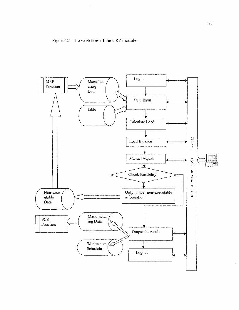
Figure 2.1 The workflow of the CRP module.
23
MRPFunction
Non-executableData
WorkcenterSchedule
Login
Data Input
Calculate Load
Load Balance
Manual Adjust
Manufactur /ing Data ( v».
V
Output the non-executableinformation
Output the result
Logout
GUI
NTERFACE
24
As showing in the figure 2.1, the CRP module is composed of 9 parts:
1. Login fonction
2. Data input fonction
3. Load calculation fonction
4. Load auto-balance fonction
5. Manual adjust fonction
6. Check the feasibility function
7. Output the non-executable information fonction
8. Data output fonction
9. Logout fonction
2.1 LOGIN FUNCTION
User must input user's ID and password for login the CRP fonction.
2.1.1 Input
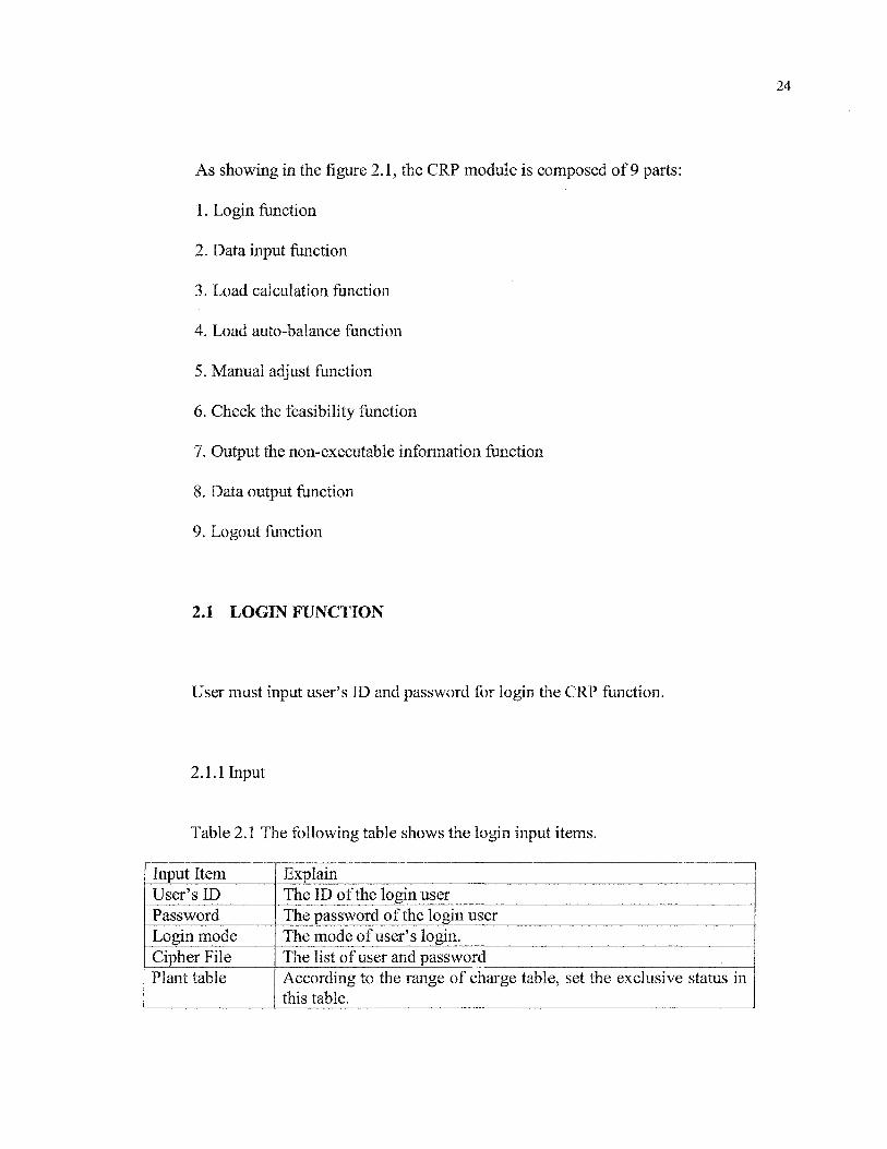
Table 2.1 The following table shows the login input items.
Input ItemUser's IDPasswordLogin modeCipher FilePlant table
ExplainThe ID of the login userThe password of the login userThe mode of user's login.The list of user and passwordAccording to the range of charge table, set the exclusive status inthis table.

25
WorkcentertableCharge tableData sourcetype
According to the range of charge table, set the exclusive status inthis table.Get the responsible range of work center from this table.Specify the type of the data source
2.1.2 Output
Table 2.2 The following table shows the login output message.
Output ItemLogin success or notType of the error
ExplainReturn the result of the login.The number of the login error.
2.1,3 Detail Process
The process logic of the login function is described as :
The fields of user ID and password must be inputted.
Reading in the Cipher file, verify the user ID and password being correct or not.
If the user ID or password is not correct, the error occurs, return the type of error.
If the user ID and password are correct, then reading in the facility table and work
center table and charge table from the specified data source.
From the charge table, get all responsible work centers of the user.
Verify the responsible work centers being used by other user. If it is the case, return
an error.
If there is no the responsible work center being used by other user, set the status of
the work center to exclusive.

26
According to the user's login mode, we can restrict the CRP fonctions which user
can be used. The following table shows this limit.
Table 2.3 Login mode
Login modePlanning
Simulation
Reference
Usable FunctionsData Input Function, Calculate LoadFunction,
Load Balance Function , Manual Adjust
Function , Non-Executable InformationOutput Function, Confirm the PlanningFunction, Data Output Function.Data Input Function, Calculate LoadFunction,
Load Balance Function , Manual Adjust
Function , Non-Executable InformationOutput Function, Confirm the PlanningFunction.Data Output Function.
2.2 DATA INPUT FUNCTION
This module reads the manufacturing orders produced by MRP from the data source
into memory. At the same time, it completes the same operation with the part table, work
center table, Calendar table etc.
2.2.1 Input
Table 2.4 Input items of the data input fonction
Input ItemManufacturing Order TableManufacturing Divided Order
NoteRead into memoryRead into memory
27
TableWorking Order TalePart TableDevice TableProcess TableProcess Sequence TableValid Process Sequence TableCalendar TableWorking Shift TableWorking Shift Type TableNon-work Period TableProducible Work center Table
Read into memoryRead into memoryRead into memoryRead into memoryRead into memoryRead into memoryRead into memoryRead into memoryRead into memoryRead into memoryRead into memory
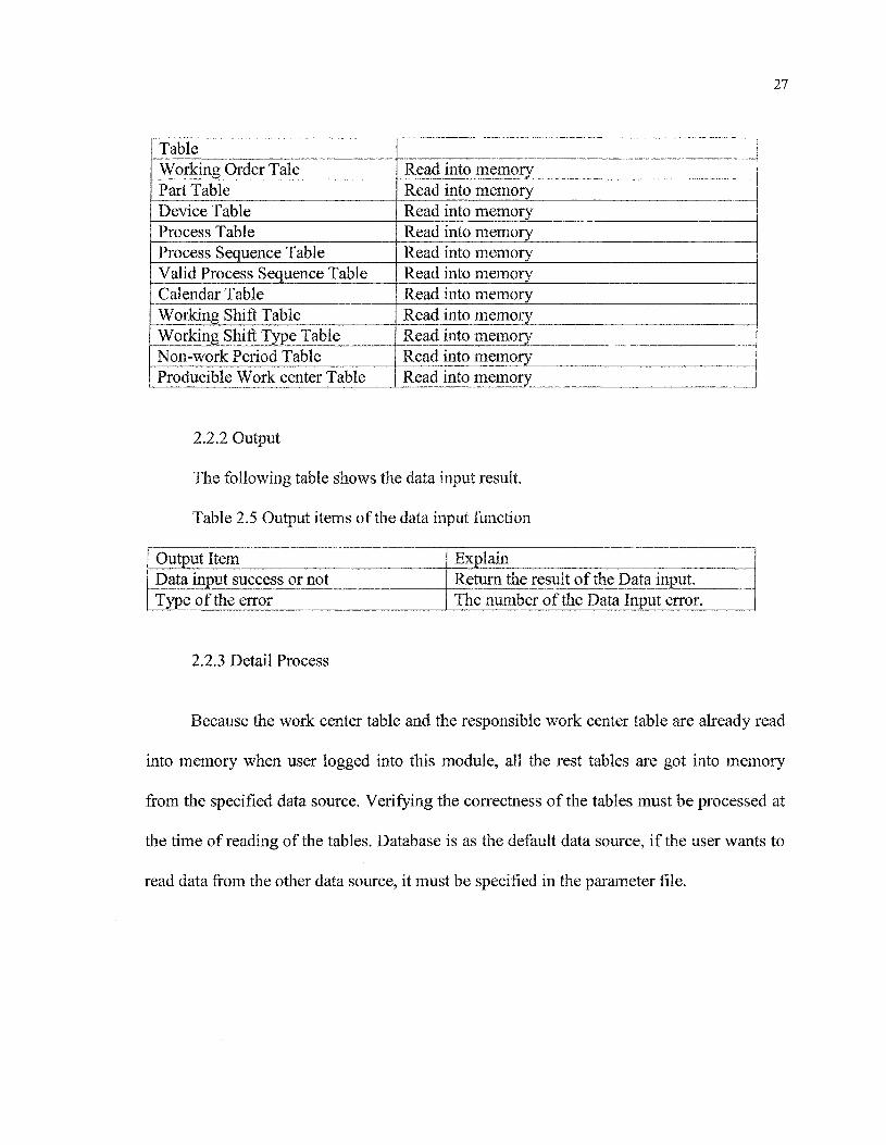
2.2.2 Output
The following table shows the data input result.
Table 2.5 Output items of the data input function
Output ItemData input success or notType of the error
ExplainReturn the result of the Data input.The number of the Data Input error.
2.2.3 Detail Process
Because the work center table and the responsible work center table are already read
into memory when user logged into this module, all the rest tables are got into memory
from the specified data source. Verifying the correctness of the tables must be processed at
the time of reading of the tables. Database is as the default data source, if the user wants to
read data from the other data source, it must be specified in the parameter file.

28
2.3 CALCULATE LOAD FUNCTION
The load calculation of the measure unit is taken by using the data read from the data
source. There are two kinds of the work area for the load calculation: the work center and
the work machine. We use the manufacturing time of each process deployed by the
manufacturing order to calculate the workload. This function also uses the information of
the process of the planned order in the posterior function (FCS) in order to achieve the high
accurate calculation of the load.
2.3.1 Input
Table 2.6 Input items of the calculate load function
Input ItemManufacturing order table
Process sequence tableWork center table
Producible work center tableCalendar table
Unit of measureBase time point of the planningThe period of the planning
NoteUsed for deploying the manufacturingprocessThe object of the loadUsed for getting the calculationalmethods of Job TimeUsed for calculating the Job TimeUsed for determining the unit of measureof the load objectUsed for calculating the loadUsed for calculating the loadUsed for calculating the load
2.3.2 Output
Table 2.7 Output items of the calculate load function
Output ItemInformation of the calculated load andthe report of the load
NoteThe load information of every unit of themeasure (each work center or each

29
| machine).The result of this function
The type of the error
If this fonction runs successfully, returnsuccess, else return an error.Return the number of the error to indicateits type.
2.3.3 Detail process
First of all, we check the input manufacturing orders whether they are the object to
calculate the load or not. If they are the object to calculate, then deploy the process of this
manufacturing order and calculate the job time of each process according to the unit of
measure. We assume that infinite capacity exists at each of these work centers to satisfy this
calculated. We use the processes that are determined by FCS fonction for the high precision
load calculation.
2.3.3.1 Verification of the manufacturing order
The LFT (Latest Finish Time) of the manufacturing order must be later than the base
time point of the planning. The EST (Earliest Start Time) of the manufacturing order must
be in the period time of the planning. The table of 2.8 shows the detail.
Table 2.8 The object to calculate load
The range of the manufacturing order
The LFT (Latest Finish Time) of the manufacturing order <the base time point of the planning
The object tocalculate loadNo
30
The base time point of the planning <= the EST (EarliestStart Time) of the manufacturing order < (the base time pointof the planning^- the period of the planning)(The base time point of the planning+ the period of theplanning) <= the EST (Earliest Start Time) of themanufacturing order
Yes
No
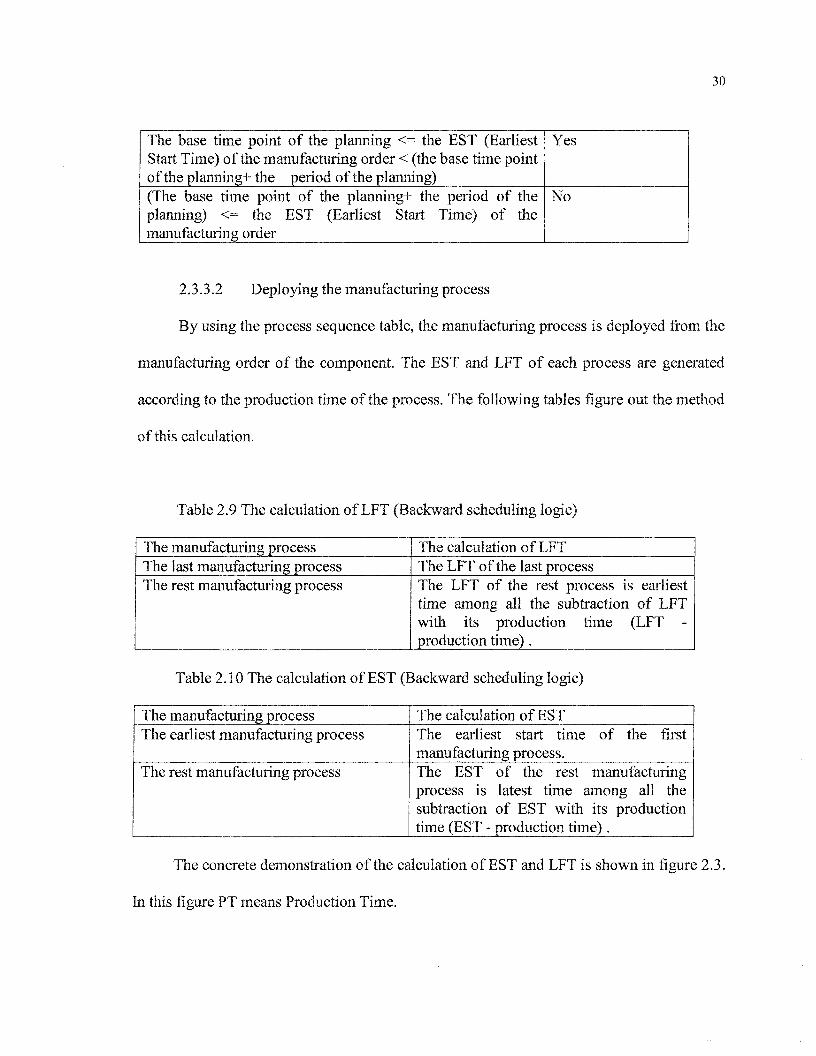
2.3.3.2 Deploying the manufacturing process
By using the process sequence table? the manufacturing process is deployed from the
manufacturing order of the component. The EST and LFT of each process are generated
according to the production time of the process. The following tables figure out the method
of this calculation.
Table 2.9 The calculation of LFT (Backward scheduling logic)
The manufacturing processThe last manufacturing processThe rest manufacturing process
The calculation of LFTThe LFT of the last processThe LFT of the rest process is earliesttime among all the subtraction of LFTwith its production time (LFT -production time) .
Table 2.10 The calculation of EST (Backward scheduling logic)
The manufacturing processThe earliest manufacturing process
The rest manufacturing process
The calculation of ESTThe earliest start time of the firstmanufacturing process.The EST of the rest manufacturingprocess is latest time among all thesubtraction of EST with its productiontime (EST - production time).
The concrete demonstration of the calculation of EST and LFT is shown in figure 2.3.
In this figure PT means Production Time.

31
Figure 2.2 The calculation of EST and LFT.
The manufacturing processes of a component X
manufacturing process A
manufacturing process B
manufacturing process C
The Calculi
EST of the component X
EST of A
EST of B
EST of C
manufacturing process D 1
ition of EST and LFT of the component X
The component X
^ PT(A) ;
<*� � � ; ; LFT of B
; ^_PT (C)->!PT(C) i ! LFT of C
i i
!PT(D) : :
ESTofD; !
manufacturing process E
LFT of A
LFT of D
LFT of the component X
LFT of E

32
2.3.3.3 The calculation of production time of the manufacturing process
The production time of the manufacturing process equals the sum of the product of
rated production time of the process and the mount of components and the prepare time.
The formulation is:
The production time = (rated production time of the process)*( the mount of
components) + the prepare time.
2.3.3.4 The different capacities and loads
The object to be calculated the load can be work center or work machine of the
manufacturing area, at the same time, the measure unit of the load can be hour or day, this
can be set in the parameter file. In the case of work center, the calculation of load is
completed according to the measure unit defined in the process sequence table. In the case
of work machine, the rules of selection the work machine to load must be followed are:
Select the machine in the top-priority work center.
In the same work center, select the top-priority machine. If it is overload, then select
the next top-priority machine.
If all machines of the center are overload, then select the top-priority machine.

33
2.3.3.5 The calculation of the standard capacity
Using the following method to calculate the standard capacity of the different
machines:
The standard capacity of the current measure unit = The sum of production time of
every day according to the measure unit.
The production time of the current day = QXthe shift production time of the current
day of the machine) + append production time )* capacity coefficient
The standard capacity of the different work centers is shown as the formula:
The standard capacity of the current measure unit = X(the standard capacities of all
machines that are belong to the current center).
2.3.3.6 The discrimination of manufacturing area
If the object to be calculated the load is work center, the load of different machines
can not be identified. Whereas in the case of the calculation load of the machine, the load of
every work center can be discriminated, because the load of the center equals to the sum of
the loads of all machines that are belong to the current center.

34
2.3.3.7 Getting the information from the fonction of the posterior planning (FCS)
This calculation load fonction also gets the information from the fonction of the
posterior planning (FCS). It uses the confirmed production orders of the posterior planning
to calculate the load so that this calculation is more accurate. The table 2.11 shows the
detail.
Table 2.11 The information introduced from the posterior planning (FCS)
InformationThe ID of process sequence of the current processThe ID of manufacturing order which includes the current processThe start time of the processThe end time of the processThe ID of the machine of the current process
The ID of planned order introduced from the fonction of the posterior planning must
be same as the ID of current manufacturing order. The ID of process sequence of the
planned order must be the same as the ID of process sequence of the current manufacturing
process deployed from the current manufacturing order. The following table shows the
information:
Table 2.12 The information deployed from the planned order
Information of theprocessEarliest start timeLatest finish time
Setting information
The start time of the process of the planned orderThe finish time of the process of the planned order
35
Production time The finish time of the process of the planned order- the starttime of the process of the planned order
The object tocalculate the load
The machine which its ID is uniform to the ID of the machine ofthe current manufacturing order.Or the work center that the machine of the planned orderbelongs to. The ID of the machine is uniform to the ID of themachine of the current manufacturing order
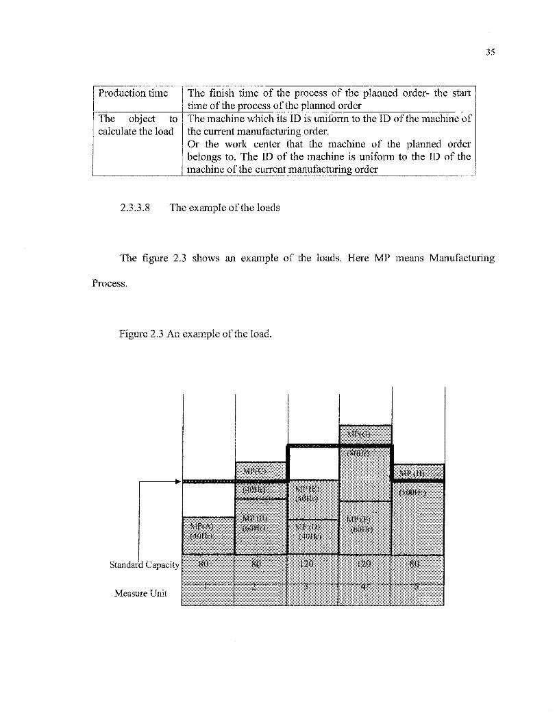
2.3.3.8 The example of the loads
The figure 2.3 shows an example of the loads. Here MP means Manufacturing
Process.
Figure 2.3 An example of the load.
Standard Capacity
Measure Unit
MP{A)(40Hr)
80
MHO
(40Hr)
MPfB)(60Hr)
80
2"
MP(E)(40Hr)
MP(D>(40Hr)
120
MI^G)
(80Hr)
�
MP(F}(60Hr)
120
MP (H)
(IQOHr)
80
5

36
2.4 AUTO-BALANCE FUNCTION
For the calculated load, the auto-balance fonction of the load is processed at the base
of the standard capacity. The result of the adjustment of the manufacturing process of this
auto-balance fonction can not be as the output of the CRP module.
2.4.1 Input
Table 2.13 The input items of the Auto-balance fonction.
Input ItemThe information of Calculate LoadFunctionWork Center Table
NoteLoad information of the work center
To get the calculate measure of the job time
2.4.2 Output
Table 2.14 The output items of the Auto-balance function.
Output ItemInformation of the calculated load andthe report of the loadThe result of this fonction
The type of the error
NoteThe load information after auto-balancefonctionIf this fonction runs successfully, returnsuccess, else return an error.Return the number of the error to indicateits type.
2.4.3 Detail process
This auto-balance load fonction will process and reschedule all open and planned

37
manufacturing orders using backward scheduling. Backward scheduling logic will calculate
each operation backwards from the manufacturing order or planned order.
The algorithm of the auto-balance load fonction we used is simple. In the case of
calculation of work center, the auto-balance load fonction is processed with the work center
as measure unit. Whereas in the case of calculation of work machine, the auto-balance load
fonction is processed with the work machine as measure unit. The loads can only be
transferred between the machines in the same work center. For the complicate auto-load
fonction, such as the transference of loads between machines in different work centers, we
don't take into account.
The detail algorithm of auto-balance load fonction is illustrated by two examples
shown in Figure 2.4-2.7.
These two examples are based on the assumption that the sequence of EST of every
manufacturing process is the same as the sequence of the English letters used to express the
process. So the EST of the manufacturing process A is the earliest, and that the EST of the
process H is the latest. Moreover, The EST of each manufacturing process is earlier than
the base point of the planning.
Example 1 of the Auto-balance, here MP means Manufacturing Process.

38
Figure 2.4 The load of the each measure unit.
Standard Capacity
Measure Unit
MP(A)<40Hr)
80
- 1
MP(B)
(40Hr)
(60Hr)
80
"1 "*"
MP(D>(40Hr)
MP<E)(40Hr)
120
3
MP(F)
MF(O)(60Hr)
120
MP(H)
(lOOHr)
80
�"' 5 " " �
As showing in the figure, because the capacity of the measure unit is over load
compared with the standard capacity, it must be taken the auto-balance process of the load.
Taking the latest measure unit 5 as the first object to be treated with, the over load
20(Hours) of the manufacturing process of the measure unit 4, as showing in the following
figure.

39
Figure 2.5 The overload 20(Hr) is transferred to measure unit 4.
Standard Capacity
Measure Unit
MPIA)<40Hr)
80
-' I-
MF(B)
(40Hr)
MP(C)(60Hf)
8Û
. � ^ ^ � ^ ^
MF(D)(40Hr)
MP{E)(40Hr)
120
V
MP(F)
(8QHr)
MP(G)(60Hr)
MP(U)2Qhf
/ 120
MP{H)
(lOOHr)
80
overload 20(Hr) is transferred to 4
After this transference to the measure unit 4, the loads of the measure unit 5 is under
the standard capacity, but the load of the measure unit 4 is over the standard capacity. So
the transference of load begins from the earliest EFT of the manufacturing process F, the
over load of 40 Hours moves ahead. This is shown in the following figure.
40
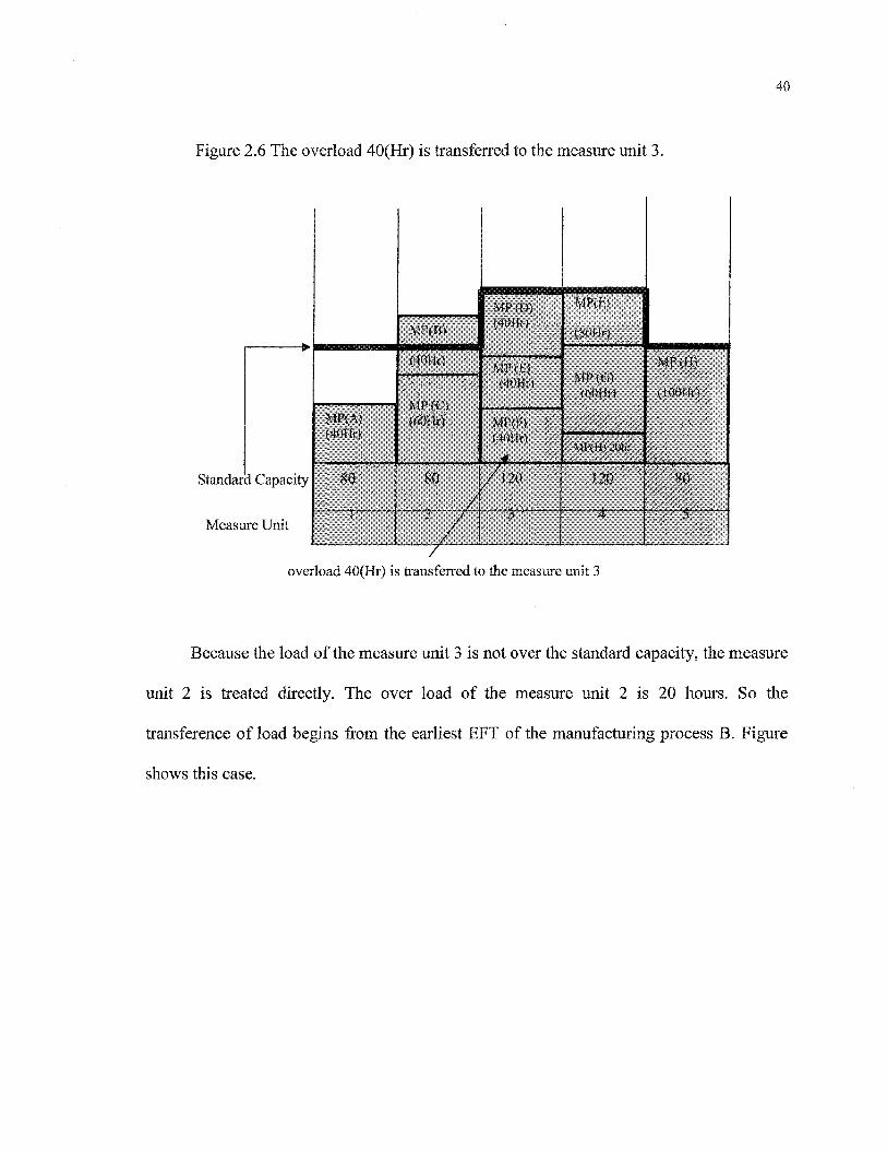
Figure 2.6 The overload 40(Hr) is transferred to the measure unit 3.
Standard Capacity
Measure Unit
MP(A)(40Hr)
80
MP(B)
(40Hr)
MP<C)(60Hr)
80
V
MP(D)(40Hr)
MP(E)(40Hr)
MP(F)l40Hr)
/l20
� 3
MP(F>
(80Hr)
MP(6)(60Hr)
MP(H)20hr
120
4'
MP(H)
(lOOHr)
80
5 '
overload 40(Hr) is transferred to the measure unit 3
Because the load of the measure unit 3 is not over the standard capacity? the measure
unit 2 is treated directly. The over load of the measure unit 2 is 20 hours. So the
transference of load begins from the earliest EFT of the manufacturing process B. Figure
shows this case.
41
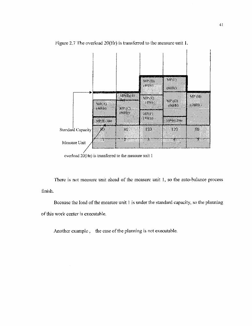
Figure 2.7 The overload 20(Hr) is transferred to the measure unit 1.
Standard Capacity
Measure Unit /
MP(A)(40Hr)
MftB)20hr
A/ t
MP(8)(40
MPrcj<60Hr)
80
MP(D)(40Hr)
(40Hr)
unv)(40Hr)
120
.->
�IIIlliiiiiftilpi
ll̂l̂lllllijiliii
MP(G)(60Hr)
MPCH)20hr
120
MP(Hî
<IOÔHr>
5
overload 20(Hr) is transferred to the measure unit 1
There is not measure unit ahead of the measure unit 1, so the auto-balance process
finish.
Because the load of the measure unit 1 is under the standard capacity5 so the planning
of this work center is executable.
Another example , the case of the planning is not executable.

42
Figure 2.8 The load of the each measure unit.
Standard Capacity
Measure Unit
MP(A)(40Hr)
80
M.P(0)(4QHv)
MP(C)
(40Hr)
MP(D)(60Hr)
80
T
MP(E)(40Hr)
MP<F)<40Hr)
120
MP(G)
(S'OHr)
MP(H)(60Hr)
120
MP (1)
(lOOHr)
80
The procedure of auto-balance of the load in this example is similar with that is in the
example 1 until the measure unit 2.
Figure 2.9 The load transference until the measure unit 2.
Standard Capacity
Measure Unit
MP(A)(40Hr)
80
1 ~""
MP(B)(40Hr)
MP(C)
' MP(D)(60Hr)
80
MP (E)(40Hr)
MP(F)(40Hr)
MP(G)(40Hr)
120
MP(G)
(80Hr)
MP(H)(60Hr)
MP(l)2t)hr
120
MP(1)
(lOOHr)
80
5

43
Because the load of the measure unit 2 is over the standard capacity, the transference
of load begins from the earliest EFT of the manufacturing process B. In this case, the load
of the manufacturing process B is less than the over part of the load of measure unit 2. So
the total load of the manufacturing process B is transferred to the measure unit 1. The
figure 2.10 shows this case.
Figure 2.10 Transfer the entire load of manufacturing process B to the measure unit1.
Standard Capacity
Measure Unit
MP(A)<40Hr)
MP(B)<40Hr)
{60Hrt
80
MP(E)(40Hr)
MP(F)(40Hr)
MP(G)<40Hr)
120
MP(G)
iSOHr)
MPtH)(6tiHr)
120
MP(f)
(JOOHr)
80
Transfer the entire load of manufacturing process B to the measure unit 1
The load of the measure unit 2 is still over load even though the entire load of
manufacturing process B is transferred to the measure unit 1. So the over load 20 Hours of

the manufacturing process C must be moved to the measure unit 1.
Figure 2.11 Transfer the overload to the measure unit 1.
Standard Capacity
Measure Unit
MR A)
(40Hr)
MF(C) 2Ohr
MP(C)(4UHr)
MP (D)<60Hr)
80
(40Hr)
MP<F)(40Hr)
MP(G)(40Hr)
120
MP(G)
(SOHr)
MP<H)(6GHr>
MP(t>20hr
120
Transfer the overload to the measure unit 1
MP<!)
(ICMIHr)
80
�r
44
There is no measure unit ahead of the measure unit 1? so the auto-balance of the load
finishes. Because the load of the measure unit 1 is over the standard capacity, in this case
the planning of the work center is non-executable.

45
2.5 MANUAL ADJUST FUNCTION
It is required to offer the means of manual adjust fonction after the load calculation.
The conceivable operations of the manual adjust fonction are listed in the following table.
Table 2.15 The operations of the manual adjust fonction.
OperationTransfer
DivideCombine
Append
Delete
Modify the quantity of theproduct
Modify the schedule and theshift type
Undo
NoteTransfer the load from one manufacturing processto an other.Divide one manufacturing order into two orders.Combine two divided orders to one manufacturingorderAppend manufacturing orders. When themanufacturing orders are appended, the validity ofMRP is not guaranteed.Remove the manufacturing orders. When themanufacturing orders are deleted, the validity ofMRP is not guaranteed.Modify the quantity of the product of themanufacturing order. When this amount ismodified, the validity of MRP is not guaranteed.Modify the day-off or the overtime of the facilityto adjust the standard capacity of the work center,so that the load is under the standard capacity.Recover the current manual operation.
2.5.1 The transference of the load
The specified load of the manufacturing process is transferred to the appointed plan
unit or work center. There are two kinds of the transference.

46
2.5.1.1 The transference of the load between the work centers
The possible moveable work centers are only those which are corresponding to the
current work sequences defined in the producible work center table. This transference can
not be performed to the work centers of the other facility. If the moveable status of the
facility is set to false, an error will occur.
2.5.1.2 The transference of the load between the work machines
The load calculation is performed using the work machine unit. The possible
moveable work machines are only those which are corresponding to the current
manufacturing process defined in the producible work center table. This transference can
not be performed to the work machines of the work center of the other facility. If the
moveable status of the machine is set to false, an error will occur.
2.5.1.3 Input
Table 2.16 The input items of the transference of the load.
Input ItemID of the manufacturing order
ID of the divided manufacturing order
ID of the manufacturing process
ID of work center or machine
Date
NoteThe ID of the manufacturing order whichincludes the manufacturing process, its loadis transferred.The ID of the divided manufacturing orderwhich includes the manufacturing process,its load is transferred.The ID of the manufacturing process, itsload is transferred.The ID of the work center or machine to betransferred.The date of manufacturing process to betransferred.
47
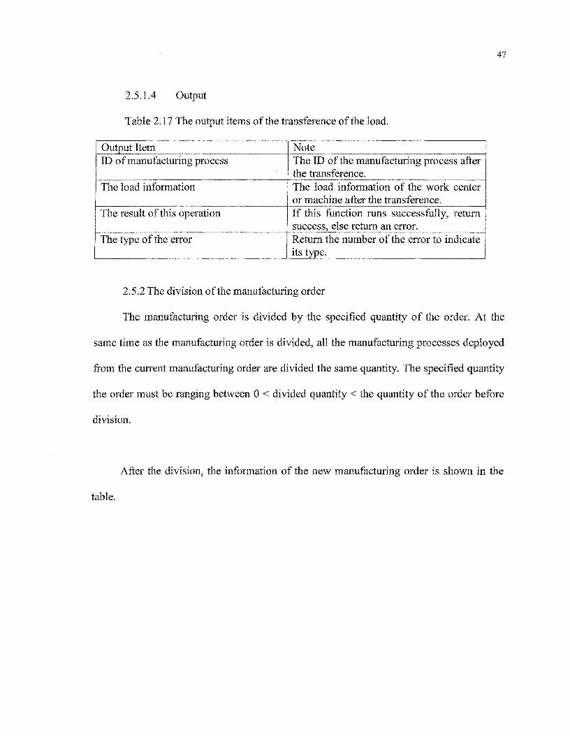
2.5.1.4 Output
Table 2.17 The output items of the transference of the load.
Output ItemID of manufacturing process
The load information
The result of this operation
The type of the error
NoteThe ID of the manufacturing process afterthe transference.The load infonnation of the work centeror machine after the transference.If this function runs successfully, returnsuccess, else return an error.Return the number of the error to indicateits type.
2.5.2 The division of the manufacturing order
The manufacturing order is divided by the specified quantity of the order. At the
same time as the manufacturing order is divided, all the manufacturing processes deployed
from the current manufacturing order are divided the same quantity. The specified quantity
the order must be ranging between 0 < divided quantity < the quantity of the order before
division.
After the division, the information of the new manufacturing order is shown in the
table.

48
Table 2.18 The information of the new manufacturing order of the division of the
manufacturing order.
Items
ID of themanufacturing orderID of the dividedmanufacturing order
ID of the component
ID of the work center
EST
LFT
Quantity
The manufacturing order 1after divisionSame as the manufacturingorder before divisionSame as the manufacturingorder before division
Same as the manufacturingorder before divisionSame as the manufacturingorder before divisionSame as the manufacturingorder before divisionSame as the manufacturingorder before divisionThe specified quantity
The manufacturing order 2after divisionSame as the manufacturingorder before divisionThe minimum value notused of the dividedmanufacturing order for thesame manufacturing orderID.Same as the manufacturingorder before divisionSame as the manufacturingorder before divisionSame as the manufacturingorder before divisionSame as the manufacturingorder before divisionThe quantity before division- quantity.
2.5.2.1 Input
Table 2.19 The input items of the division of the manufacturing order.
Input ItemID of he manufacturing order
ID of the divided manufacturing order
Quantity
NoteThe ID of the manufacturing order to bedivided.The ID of the divided manufacturing orderto be divided.The quantity of the manufacturing orderafter division.

49
2.5.2.2 Output
Table 2.20 The output items of the division of the manufacturing order.
Output ItemManufacturing order 1Manufacturing order 2The load information
The result of this operation
The type of the error
NoteThe manufacturing order 1 after divisionThe manufacturing order 2 after division.The load information of the work centeror machine after the division.If this function runs successfully, returnsuccess, else return an error.Return the number of the error to indicateits type.
2.5.3 The Combination of the manufacturing order
The combination of the manufacturing order is performed by two specified
manufacturing orders. After combination these two manufacturing orders, all the
manufacturing processes deployed from these two manufacturing orders must be combined
together. The quantity of the manufacturing order after combination is the sum of two
combined manufacturing orders. The ID of the divided manufacturing order is the minor
value of these two IDs of the divided manufacturing orders. The other information except
the quantity and the ID of the divided manufacturing order will inherit the same
information of the manufacturing order. The combination can only be performed between
the divided manufacturing orders which have the same manufacturing order ID.
50
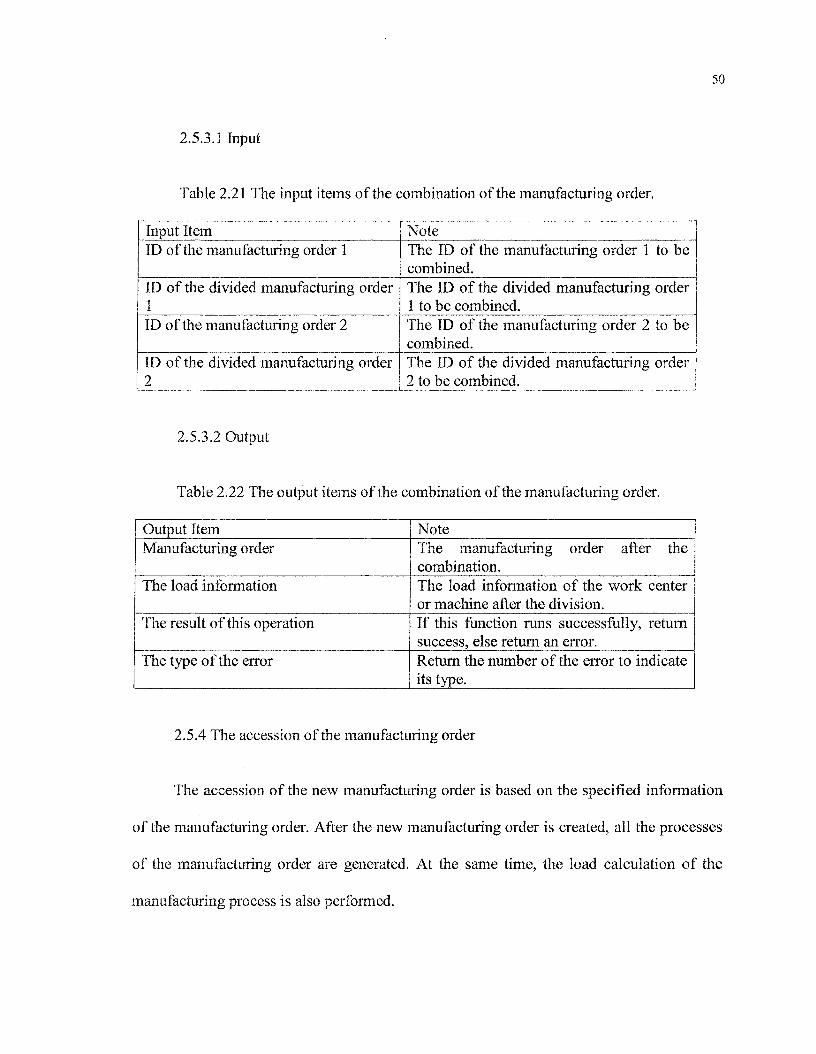
2.5.3.1 Input
Table 2.21 The input items of the combination of the manufacturing order.
Input ItemID of the manufacturing order 1
ID of the divided manufacturing order1ID of the manufacturing order 2
ID of the divided manufacturing order2
NoteThe ID of the manufacturing order 1 to becombined.The ID of the divided manufacturing order1 to be combined.The ID of the manufacturing order 2 to becombined.The ID of the divided manufacturing order2 to be combined.
2.5.3.2 Output
Table 2.22 The output items of the combination of the manufacturing order.
Output ItemManufacturing order
The load information
The result of this operation
The type of the error
NoteThe manufacturing order after thecombination.The load information of the work centeror machine after the division.If this function runs successfully, returnsuccess, else return an error.Return the number of the error to indicateits type.
2.5.4 The accession of the manufacturing order
The accession of the new manufacturing order is based on the specified information
of the manufacturing order. After the new manufacturing order is created, all the processes
of the manufacturing order are generated. At the same time, the load calculation of the
manufacturing process is also performed.

51
2.5.4.1 Input
Table 2.23 The input items of the accession of the manufacturing order.
Input ItemAll the necessary information of newmanufacturing order
NoteInput the necessary information for creatingthe new manufacturing order.
2.5.4.2 Output
Table 2.24 The output items of the accession of the manufacturing order.
Output ItemManufacturing order
The load information
The result of this operation
The type of the error
NoteThe new manufacturing order after theaccession.The load information of the work centeror machine after the accession.If this function runs successfully, returnsuccess, else return an error.Return the number of the error to indicateits type.
2.5.5 The deletion of the manufacturing order
Deleting a manufacturing order is performed by specified its ID, at the same time, all
manufacturing processes deployed by the current manufacturing order are also removed.
2.5.5.1 Input
Table 2.25 The input items of the deletion of the manufacturing order.
Input ItemID of the manufacturing order
ID of the divided manufacturing order
NoteThe ID of the manufacturing order to beremoved.The ID of the divided manufacturing orderto be deleted.

52
2.5.5.2 Output
Table 2.26 The output items of the deletion of the manufacturing order.
Output ItemManufacturing orderThe load information
The result of this operation
The type of the error
NoteThe manufacturing order to be deleted.The load information of the work centeror machine after the deletion.If this function runs successfully, returnsuccess, else return an error.Return the number of the error to indicateits type.
2.5.6 The modification of the quantity of the manufacturing order
Modifying the quantity of a manufacturing order is performed by specified its new
quantity at the same time, all manufacturing processes deployed by the current
manufacturing order are also modified.
2.5.6.1 Input
Table 2.27 The input items of the modification of the quantity of the manufacturing
order.
Input ItemID of the manufacturing order
ID of the divided manufacturing order
The Quantity
NoteThe ID of the manufacturing order to bemodified.The ID of the divided manufacturing orderto be modified.The new quantity of the manufacturingorder.

53
2.5.6.2 Output
Table 2.28 The output items of the modification of the quantity of the manufacturing
order.
Output ItemManufacturing order
The load information
The result of this operation
The type of the error
NoteThe manufacturing order to be modifiedits quantity.The load information of the work centeror machine after the modification.If this function runs successfully, returnsuccess, else return an error.Return the number of the error to indicateits type.
2.5.7 The modification of the schedule and the shift type
The objective of modifying the day-off or the overtime of the facility is to adjust the
standard capacity of the work center, so that the load is under the standard capacity. There
are four types of the modifications listed in the following table.
Table 2.29 The operations of the modification of the shift.
OperationModify the shift type
Append the overtime
Append the day-offDelete the day-off
NoteModify the shift type of the specifiedwork center or machine to the other typeof the shift.Append the overtime of the work centerwill change the overtime of all machinesof this work center.Append the day-off of the work machine.Delete the day-off of the work machine.

54
5.2.8 Undo operation
For the manual operations, the Undo mechanism is necessary. In one case, if the
input parameters of the manual operation are not correct, the Undo operation must be
performed. In the other case, when several manual operations are executed, we want to
recover the one of them. So the Undo mechanism can satisfy this requirement.
The level of the Undo operation can be set in the parameter file.
2.6 CHECK THE FEASIBILITY OF THE PLANNING
This module is to check the load of the measure unit whether is under the standard
capacity or not.
2.6.1 Input
Table 2.30 The input items of the verification of the feasibility of the planning.
Input ItemID of the work center (machine)
The load information
NoteCheck the feasibility of planning of thespecified work center (machine).Use the load information to check thefeasibility.
2.6.2 Output
Table 2.31 The output items of the verification of the feasibility of the planning.
Output ItemThe result of this operation
Arrange the measure unit
NoteIf the planning of the work center isexecutable, return true, else return false.General view of the non-executablemeasure unit.
55
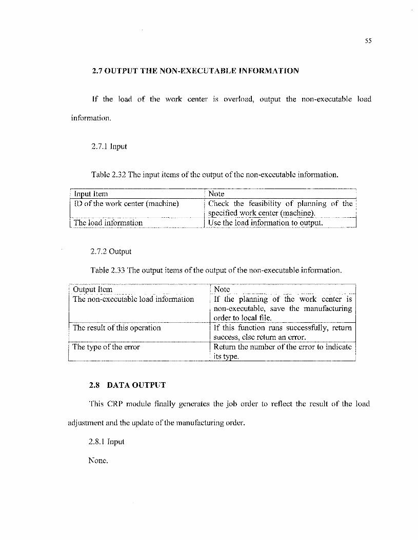
2.7 OUTPUT THE NON-EXECUTABLE INFORMATION
If the load of the work center is overload, output the non-executable load
information.
2.7.1 Input
Table 2.32 The input items of the output of the non-executable information.
Input ItemID of the work center (machine)
The load information
NoteCheck the feasibility of planning of thespecified work center (machine).Use the load information to output.
2.7.2 Output
Table 2.33 The output items of the output of the non-executable information.
Output ItemThe non-executable load information
The result of this operation
The type of the error
NoteIf the planning of the work center isnon-executable, save the manufacturingorder to local file.If this function runs successfully, returnsuccess, else return an error.Return the number of the error to indicateits type.
2.8 DATA OUTPUT
This CRP module finally generates the job order to reflect the result of the load
adjustment and the update of the manufacturing order.
2.8.1 Input
None.

2.8.2 Output
Table 2.34 The output items of the data output function.
2.9 LOGOUT
56
Output ItemThe manufacturing orderThe job orderThe shift
NoteReflect the adjustment of loadReflect the adjustment of loadReflect the adjustment of load
Logout function exits the current CRP module and saves the necessary information.
There is no input data and output data involved in this part.
CHAPTER 3
CLASS DESCRIPTIONS
This chapter will discuss the data input? the load calculation and manual adjust parts.
Each part contains an associated class for which their behavior and data will describe. The
class descriptions will include a statement of purpose and description of both the public and
private declarations. The other parts (login5 data output and Undo fonction) will not be
discussed.
3.1 THE UML OF THE CRP MODULE
This CRP module contains 9 domains as showing in figure 3.1. Each domain
comprises several classes. The Figure 3.1 illustrates the UML of these classes.
The Figure 3.1 The UML of the classes.

58
59
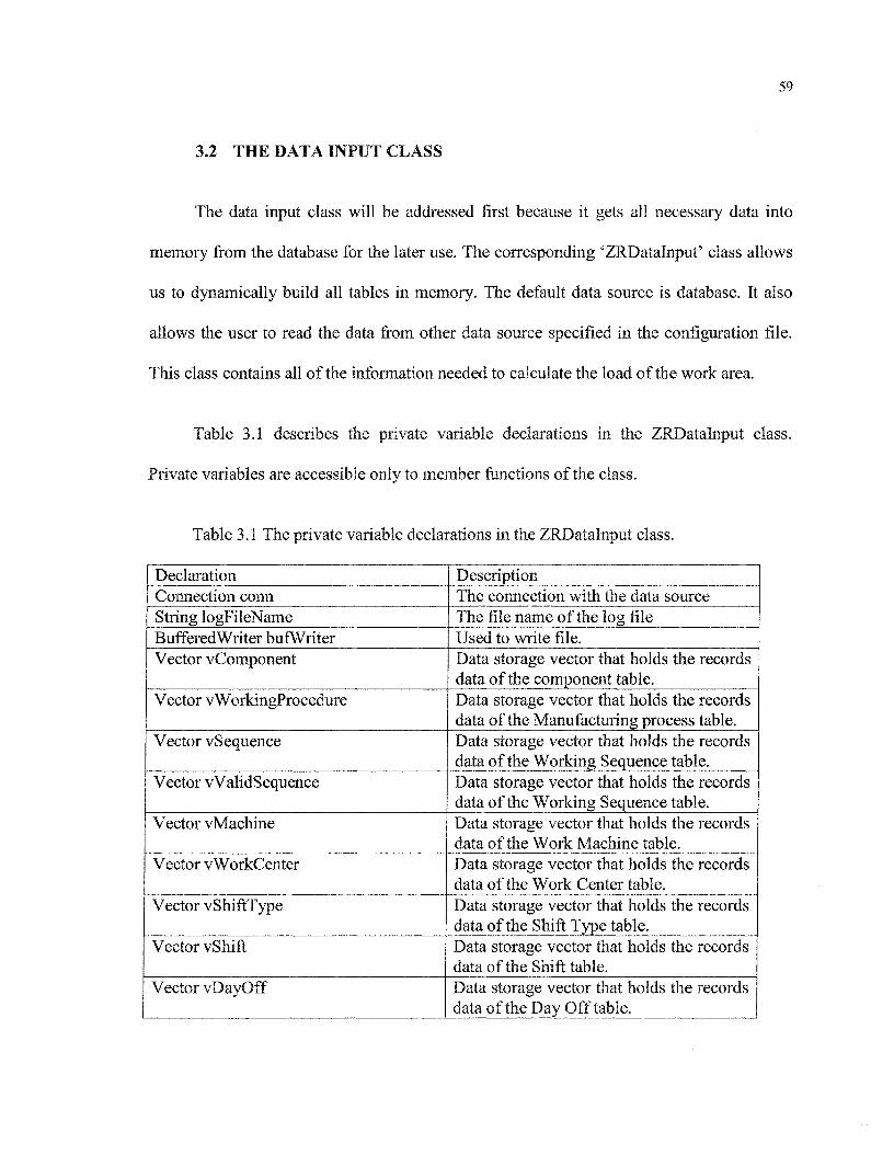
3.2 THE DATA INPUT CLASS
The data input class will be addressed first because it gets all necessary data into
memory from the database for the later use. The corresponding 'ZRDatalnput5 class allows
us to dynamically build all tables in memory. The default data source is database. It also
allows the user to read the data from other data source specified in the configuration file.
This class contains all of the information needed to calculate the load of the work area.
Table 3.1 describes the private variable declarations in the ZRDatalnput class.
Private variables are accessible only to member fonctions of the class.
Table 3.1 The private variable declarations in the ZRDatalnput class.
DeclarationConnection connString logFileNameBufferedWriter bufWriterVector vComponent
Vector vWorkingProcedure
Vector vSequence
Vector vValidSequence
Vector vMachine
Vector vWorkCenter
Vector vShiftType
Vector vShift
Vector vDayOff
DescriptionThe connection with the data sourceThe file name of the log fileUsed to write file.Data storage vector that holds the recordsdata of the component table.Data storage vector that holds the recordsdata of the Manufacturing process table.Data storage vector that holds the recordsdata of the Working Sequence table.Data storage vector that holds the recordsdata of the Working Sequence table.Data storage vector that holds the recordsdata of the Work Machine table.Data storage vector that holds the recordsdata of the Work Center table.Data storage vector that holds the recordsdata of the Shift Type table.Data storage vector that holds the recordsdata of the Shift table.Data storage vector that holds the recordsdata of the Day Off table.
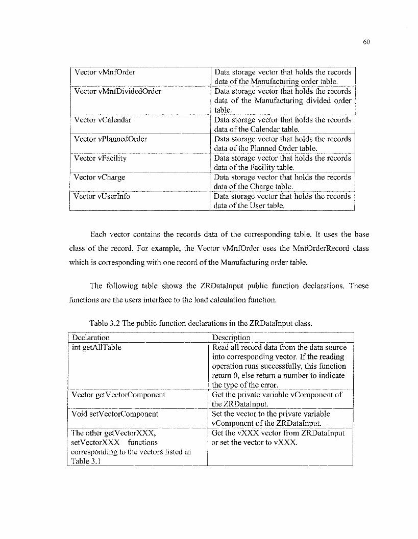
60
Vector vMnfOrder
Vector vMnfDividedOrder
Vector vCalendar
Vector vPlannedOrder
Vector vFacility
Vector vCharge
Vector vUserlnfo
Data storage vector that holds the recordsdata of the Manufacturing order table.Data storage vector that holds the recordsdata of the Manufacturing divided ordertable.Data storage vector that holds the recordsdata of the Calendar table.Data storage vector that holds the recordsdata of the Planned Order table.Data storage vector that holds the recordsdata of the Facility table.Data storage vector that holds the recordsdata of the Charge table.Data storage vector that holds the recordsdata of the User table.
Each vector contains the records data of the corresponding table. It uses the base
class of the record. For example, the Vector vMnfOrder uses the MnfOrderRecord class
which is coiresponding with one record of the Manufacturing order table.
The following table shows the ZRDatalnput public fonction declarations. These
fonctions are the users interface to the load calculation fonction.
Table 3.2 The public fonction declarations in the ZRDatalnput class.
Declarationint getAUTable
Vector getVectorComponent
Void setVectorComponent
The other getVectorXXX?
setVectorXXX fonctionscorresponding to the vectors listed inTable 3.1
DescriptionRead all record data from the data sourceinto corresponding vector. If the readingoperation runs successfully, this fonctionreturn 0, else return a number to indicatethe type of the error.Get the private variable vComponent ofthe ZRDatalnput.Set the vector to the private variablevComponent of the ZRDatalnput.Get the vXXX vector from ZRDatalnputor set the vector to vXXX.

61
Table 3.3 shows the private function declarations of the ZRDatalnput class.
Declarationint getComponentTable
int checkComponentRecord
The other getXXXTable andcheckXXXRecord fonctionscorresponding to the vectors listed inTable 3.1
DescriptionRead the record data from the Componenttable into the corresponding vectorvComponent. If the reading operationruns successfolly5 this fonction return 0,else return a number to indicate the typeof the error.When this fonction reads the Componentdata from the data source, it must betaken the verification of correctness ofthe Component record.Read the record data from the XXX tableinto the corresponding vector vXXX. Ifthe reading operation runs successfully,this fonction return 0? else return anumber to indicate the type of the error.
3.3 LOAD CALCULATION CLASS
The ZRLoadCalcul class is the most important class in this module, because it
performs not only the load calculation of the work area according to the measure unit, it
also takes the task of auto-balance of the load. The load calculation is performed by using
the work time of each manufacturing process deployed by the manufacturing order.
The auto-balance load fonction will process and reschedule all open and planned
manufacturing orders using backward scheduling. Backward scheduling logic will calculate
each operation backwards from the manufacturing order or planned order.
62
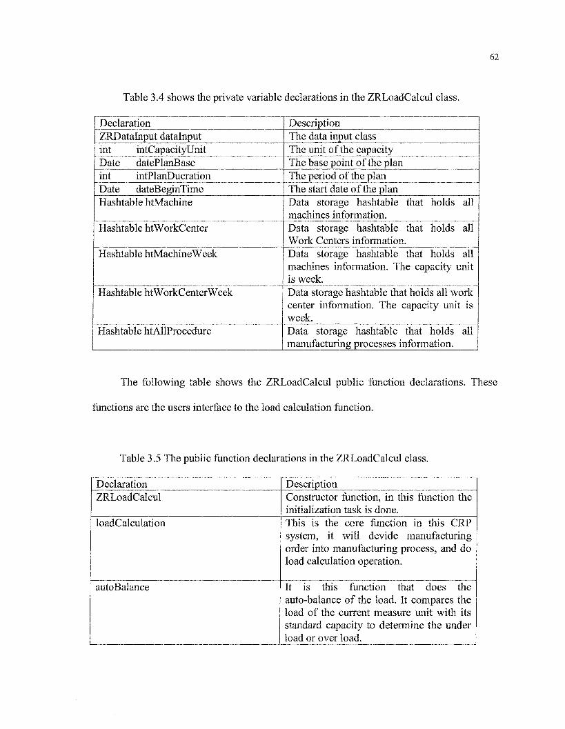
Table 3.4 shows the private variable declarations in the ZRLoadCalcul class.
DeclarationZRDatalnput datalnputint intCapacityUnitDate datePlanBaseint intPlanDucrationDate dateBeginTimeHashtable htMachine
Hashtable htWorkCenter
Hashtable htMachineWeek
Hashtable htWorkCenterWeek
Hashtable htAHProcedure
DescriptionThe data input classThe unit of the capacityThe base point of the planThe period of the planThe start date of the planData storage hashtable that holds allmachines information.Data storage hashtable that holds allWork Centers information.Data storage hashtable that holds allmachines information. The capacity unitis week.Data storage hashtable that holds all workcenter information. The capacity unit isweek.Data storage hashtable that holds allmanufacturing processes information.
The following table shows the ZRLoadCalcul public fiinction declarations. These
functions are the users interface to the load calculation fiinction.
Table 3.5 The public function declarations in the ZRLoadCalcul class.
DeclarationZRLoadCalcul
loadCalculation
autoBalance
DescriptionConstructor function, in this function theinitialization task is done.This is the core function in this CRPsystem, it will dévide manufacturingorder into manufacturing process, and doload calculation operation.
It is this fiinction that does theauto-balance of the load. It compares theload of the current measure unit with itsstandard capacity to determine the underload or over load.

63
getLoadlnformation
getUnexecutablelnformation
This fonction returns all load informationof the work center or work machine.This fonction returns all load informationof the measure unit that their capacity areover load
Table 3.6 The private fonction declarations of the ZRLoadCalcul class.DeclarationinitWorkCenterByDay
initWorkMachineByDay
initWorkCenterByWeek
initWorkMachineByWeek
DescriptionInitialize the WorkCenter by day5createinstances of ZRWorkCenter class and putthem into Hashtable variablehtWorkCenter
Initialize the WorkMachine by day,createinstances of ZRWorkMachine class andput them into Hashtable variablehtWorkMachine
Initialize the WorkCenter by week5createinstances of ZRWorkCenter class and putthem into Hashtable variablehtWorkCenterWeek
Initialize the Machine by week5createinstances of ZRMachine class and putthem into Hashtable variablehtMachineWeek
3.4 MANUAL ADJUST CLASSES
As discussed in chapter 5, the manual adjust part consists of 8 operations. These
operations are base on the interface 'ZRManualAdjust9. Here I will discuss one class for
illustration: the class ZRLoadTransfer. The other classes are similar to this class. You can
find them in the Index C.

64
3.4.1 The interface ZRManualAdjust
The following table shows the public fonctions placed in the interface
ZRManualAdjust.
Table 3.7 The public functions placed in the interface ZRManualAdjust.
DeclarationVoid setParameter
Vector getParameter
Hashtable[] getExistedRecords
int changeExistedRecords
DescriptionThis interface sets the necessaryparameters of the manual operation.This interface gets the input parametersof the manual operation.This interface gets all necessary existedhashtable to perform the manualoperation.This interface performs the manualoperation.
3.4.2 Load transfer class
ZRLoadTransfer class is corresponding to the load transference operation. There are
two kinds of the transference: the load between the work centers and the load between the
work machines.
Table 3.8 Shows the private variable declarations in the ZRLoadTransfer class.
DeclarationZRDatalnput zrDatalnputZRLoadCalcul zrLoadCalculBoolean moveFlagVector vLoadTransferlnfoHashtable[] existedOrderRecords
DescriptionThe class instance of class ZRDatalnputThe class instance of class ZRLoadCalculThe flag of the transference operationThe vector stores the parameter list.The existed manufacturing orderhashtable.

65
Table 3.9 shows the public variable declarations in the ZRLoadTransfer class.
DeclarationOperationObject oo
UndoList ul
DescriptionThe class object is prepared for the Undooperation.The Undo list used for the Undooperation.
Because the class ZRLoadTransfer extends the interface ZRManualAdjust, the public
functions of this class are the same as shown in the table 6.4.1.
3.5 CRP TASK CLASS
I design the ZRCRPTask class to provide the interfaces of all of the tasks described
in the previous chapters. This is for two purposes. The first is that the CRP module will
work as a whole to integrate to the ZRERP system. The second is that this module can work
independently, so we can use this class to interact with the GUI classes.
Table 3.10 shows the private variable declarations in the ZRCRPTask class.
DeclarationZRConnection crpconnZRDatalnput zrDatalnputZRDataOutput zrDataOutputZRLogin zrLoginZRLoadCalcul zrLoadCalculZRLoadTransfer zrLoadTransfer
ZROrderDivide zrOrderDivide
ZROrderAppend zrOrderAppend
DescriptionOpen the connection with the data sourceThe class instance of class ZRDatalnputThe class instance of class ZRDataOutputThe class instance of class ZRLoginThe class instance of class ZRLoadCalculThe class instance of the classZRLoadTransfer to perform the loadtransference operation of manual adjust.The class instance of the classZROrderDivide to perform the loaddivision operation of manual adjust.The class instance of the classZROrderAppend to perform the orderappend operation of manual adjust.

66
ZROrderUnite zrOrderUnite
ZROrderQuantityChgzrOrderQuantityChg
ZRShiftChg zrShiftChg
ZRDayOffAppend zrDayOffAppend
The class instance of the classZROrderUnited to perform the ordercombination operation of manual adjust.The instance of the classZROrderQuantityChg to perform themodification of the quantity of themanufacturing order.The instance of the class ZRShiftChg toperform the modification the type of theshift.The instance of the classZRDayOffAppend to append the day-offof the work center or machine.
Table 3.11 shows the public variable declarations in the ZRCRPTask class.
DeclarationUndoList undoListint undoNum
DescriptionThe list to perform the undo operation.The number of Undo times.
The table 3.12 shows the public fonction declarations in the ZRCRPTask class.
These fonctions are used by other modules or by the GUI fonctions.
Table 3.12 The public fonction declarations in the ZRCRPTask class.
Declarationint initQ
int login
DescriptionThis fonction will perform the necessaryinitialization of the ZRCRPTask class,such as preparing the databaseconnection, reading the configuration fileand initializing the private variables.When the initialization operation runssuccessfully, it returns 0, else an errornumber occurs.This fonction will do the login action asdescribed in chapter 4. When user logs insuccessfully, it returns 0, else an errornumber occurs.

67
int datalnput
int loadCalculateQ
int autoBalance
Vector getLoadlnfo
int orderDivide
int orderUnite
int orderAppend
int orderDelete
int quantityChange
This fonction will read all tables into thememory as described in chapter 4. Whenit runs successfully, it will return 0?
else an error number occurs.This function will perform the loadcalculation as described in chapter 4.When it runs successfully, it returns 0,else an error number occurs.This function will perform the loadauto-balance operation as described inchapter 4. When it runs successfully, itreturns 0, else an error number occurs.This fonction will get the loadinformation of the specified work centeror work machine. When it runssuccessfully, it returns a Vector whichcontains the load information, else itreturns NULL.This fonction will divide a specifiedmanufacturing order into twomanufacturing orders as described inchapter 4. When it runs successfully,it returns 0, else an error number occurs.This fonction will combine the specifiedtwo manufacturing orders into onemanufacturing order as described inchapter 4. When it runs successfully,it returns 0, else an error number occurs.This fonction will append a newmanufacturing order as described inchapter 4. When it runs successfully,it returns 0, else an error number occurs.This fonction will delete a specifiedmanufacturing order as described inchapter 4. When it runs successfully, itreturns 0, else an error number occurs.This fonction will change the quantity ofthe specified manufacturing order asdescribed in chapter 4. When it runssuccessfully, it returns 0, else an errornumber occurs.

int shiftChange
int dayOffAppend
int getNonExecutablelnfo
int unDo
int checkFeasibility
int dataOutput
int logout
This fonction will change the shift type ofthe specified work center as described inchapter 4. When it runs successfully, itreturns 05 else an error number occurs.This fonction will append the day-off ofthe specified work center or machine asdescribed in chapter 4. When it runssuccessfully, it returns 0? else an errornumber occurs.This fonction will get the non-executableinformation of the specified work centeror machine as described in chapter 4.When it runs successfully, it returns aVector which contains the loadinformation, else it returns NULL.Calling this fonction one time to cancelthe last operation in the unDoListThis fonction will check the feasibility ofthe planning, i.e. the load of the measureunit is under the standard capacity or not.If the planning is feasible, it returns 0,else either the planning is not feasible 1or an error number (>1) occurs.This fonction will write back all memorydata into the data source, at the same timeoutput the necessary information into thelocal file. When it runs successfully, itreturns 0, else an error number occurs.This fonction will do the logout action toexit this module. When user logs outsuccessfully, it returns 0, else an errornumber occurs.

CHAPTER 4
IMPLEMENTATION
The current implementation of this CRP module supports two types of the data
source. One is Oracle 8i and another is text format file (Comma Separated Value -CSV).
For the text format file, the CsvJDBC driver must be used. It is just like any other JDBC
driver. The csvjdbc.jar file should be included in the application's classpath.
Because Java is the platform independent, so the program is designed to run on any
platform. The following figure shows the login window of the CRP module.
Figure 4.1 Login window of the CRP module.
username
password
mode
login
Sunny
cancel

70
As described in chapter 2, when user logged in correctly, the data input function was
performed automatically. So all the data of the data source is read into memory. Then the
main frame of the CRP module was shown, as showing in figure 4.2.
Figure 4.2 The main frame of this CRP module.
File Graphic Output LoadCaJcutate Auto-Balanss fVianuaJ Adjust Tools
CRP SYSTEM (ZRCRP V U )Mar, 2005
As discussed in chapter 2, this CRP module contains load calculation, auto-balance,
manual adjust and data output fonctions. Each function is corresponding to a menu item in
the main frame. The menu items of the manual adjust are displayed in figure 4.3.

71
Figure 43 The menu items of the manual adjust operations.
File Graphic Output LoadCaieulate Auto-Balance | f l ^B l iSSIB3 i T o o l s
Order Transfer
Order Divide
CRP SYSTEM (ZRCRP V Order DeleteMar, 2005
Quantity
UnDo
Here we give an example of the order transferring operation for illustration.
Figure 4.4 The order transference operation.
Order Transfer
Order ID
Divide HO
Procedure 10
Unit IP
Date
1 OK I
joooi
P2
1 W6
j
12/6/2004
Cancel \
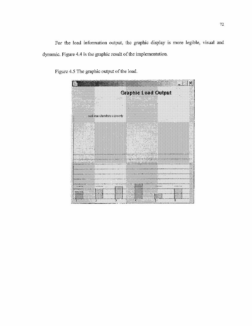
72
For the load information output, the graphic display is more legible, visual and
dynamic. Figure 4.4 is the graphic result of the implementation.
Figure 4.5 The graphic output of the load.
Graphic Load Output
,�., ted fmeistancfard capacity

CONCLUSION
Materials Requirements Planning is a new information system program and its rather
simple mission was to schedule manufacturing processes to meet customer needs as laid out
in a Master Production Schedule (MPS). The MPS come from the individual product
forecasts and is intended to ensure that customers get what they want in a timely fashion. A
problem arose early on5 however, the MPS might not be feasible with available capacity.
The MPS might call for more units to be produced in a period than the factory could handle.
The simple solution is to move some of the production to an earlier or later time period.
This required an understanding of customer requirements and capacity restrictions.
Critical customers would have to be moved to earlier periods to avoid a stock-out that could
damage important relationships. Capacity Requirements Planning (CRP) is added to further
enhance MRP and allow for complete and feasible scheduling of manufacturing lines.
In this paper I introduced the requirements analysis, the detail design and the
implementation of the CRP module. The load calculation is performed by taking into
account of the planned orders in the posterior planning function (FCS) to achieve the
calculation more accurate. The load auto-balance fonction is designed to enable verifying
the feasibility of the planning by the means of comparing the added load with its standard
capacity of the measure unit. I used the backward load scheduling (infinite) method to

74
perform the load auto-balance function. As shown in chapter 4,1 realized the graphic load
displaying. In chapter 291 also described the manual adjust operations. The purpose of these
operations is to offer the manual means to adjust the planning.
The class descriptions in chapter 3 explicitly describe the functions involved in the
load calculation, the auto-balance and the manual adjust fonctions. Class declarations and
access are also listed here. Public and private fonctions and data members ensure that data
is not accidentally changed by some outside source.
Design of the CRP module is based on the principles of Object Oriented Design and
Object Oriented Programming (OOD/OOP). To further facilitate this all code is written
using Java. This language was also chosen based on the ease of extensibility of completed
code.
In conclusion I believe this implementation of the CRP module to be a big step in
ZRERP system. Many and varied ERP systems may be evaluated to do the same job.
REFERENCES
[1] LUO HONG, THE PRINCIPLE & DESIGN & IMPLEMENTATION OF ERP,
ELECTRONIC AND INDUSTRIAL PUBLISHING COMPANY OF CHINA, BEIJING,
2002.
[2] LUO HONG, THE PRINCIPLE & DESIGN & IMPLEMENTATION OF ERP
(SECOND EDITION), ELECTRONIC AND INDUSTRIAL PUBLISHING COMPANY
OF CHINA, BEIJING, 2003.
[3] ZHENG MING KUAN , HE NINQ ENTERPRISE RESOURCE PLANNING:
THEORY AND PRACTICE, SCIENCE AND TECHNOLOGY PUBLISHING COMPANY
OF CHINA, BEIJING, 2004.
[4] LIU BO YING, ZHOU YU QING, THEORY AND IMPLEMENTATION OF
MRPII/ERP, TIANJIN UNIVERSITY PUBLISHING COMPANY, 2001.
[5] WRIGHT O W. MRPII: UNLOCKING AMERICA'S PRODUCTIVITY POTENTIAL.
REVISED EDITION. OLIVER WRIGHT LIMITED PUBLICATIONS, INC., 1984
[6] LUBER A D. SOLVING BUSINESS PROBLEMS WITH MRPII. DIGITAL PRESS,
1991
LANDVATER D V, GRAY C D. MRPII STANDARD SYSTEM. JOHN WILEY & SONS,
INC., 1989
[7] CHASE R B, AQUILANO N J, JACOBS F R. PRODUCTION AND OPERATIONS

76
MANAGEMENT.
[8] JAMES RUMBAUGH,IVAR JACOBSON,UNIFIED MODELING LANGUAGE
USER GUIDE, ADDISON WESLEY,1998.
[9] JAMES W. COOPER,THE DESIGN PATTERNS JAVA COMPANION, 1998.
[10]LEARNING JAVA WITH JBUILDER, SCOTTS VALLEY, CA 95066-3249.
[11]ENTERPRISE APPLICATION DEVELOPER'S GUIDE, VERSION 4,SCOTTS
VALLEY,CA 95066-3249.

APPENDIX A
CLASS TABLE
Class NameZRCRPTaskZRConnectionZRLoginZRDatalnput
ZRLoadCalcul
ZRManualAdjustZRDataOutputZRLogout
ZROrderDelete
ZRLoadTransferZRShiftChgZROrderDivideZROrderUniteZROrderAppendZRDayOffAppendCalendarDBCalendarDBImpl
CalendarRecord
ChargeDBChargeDBImplChargeRecordMachineDBMachineDBImplMachineRecord
FactoryDB
FactoryDBImplFactoryRecordMnfOrderDBMnfOrderDBImpl
DescriptionThe interface class of GUIConnecting to data sourceLogging in this ModuleReading the data into memoryCalculating the load and doing theauto-balanceThe interface to do manual adjustOutput the dataLogging outDeleting the specified order
Transferring the loadModifying the shiftDividing the orderCombining the orderAppend the orderAppend the day-offThe interface of CalendarDBImplOperating the calendar tableStoring the calendar record
The interface of the ChargeDBImplOperating the charge tableStoring the charge recordThe interface of MachineDBImplOperating the machine tableStoring the machine recordThe interface of FactoryDBImpl
Operating the facility tableStoring the facility recordThe interface of MnfOrderDBImplOperating the manufacturing order table

78
MnfOrderRecordMnfOrderDivideDBMnfOrderDivideDBImplMnfOrderDivideRecordPartDBPartDBImplPartRecordProduceableTimeDBProduceableTimeDBImplProduceableTimeRecordSequenceDB
SequenceDBImpl
SequenceRecord
WorkOrderDB
WorkOrderDBImpi
WorkOrderRecord
WorkCenterDB
WorkCenterDBImpl
WorkCenterRecord
WorkingProcedureDB
WorkingProcedureDBImpl
WorkingProcedureRecord
ValidSequenceDBValidSequenceDBImplValidSequenceRecord
WorkCenterDay
WorkCenterWeek
MachineDay
MachineWeek
ZRException
Storing the manufacturing order recordThe interface of MnfOrderDivideDBImplOperating the manufacturing order detail tableStoring the manufacturing order detail recordThe interface of PartDBImplOperating the component tableStoring the component tableThe interface of ProduceableTimeDBImplOperating the producible time tableStoring the producible time recordThe interface of SequenceDBImplOperating the process sequence table
Storing the process sequence record
The interface of WorkOrderDBImpi
Operating the work order table
Storing the work order record
The interface of WorkCenterDBImpl
Operating the work center table
Storing the work center record
The interface of WorkingProcedureDBImpl
Operating the process table
Storing the process record
The interface of the ValidSequenceDBImplOperating the valid process sequence tableStoring the valid process sequence recordStoring the information of the work center bydayStoring the information of the work center byweekStoring the information of the work machineby dayStoring the information of the work machineby weekThe exceptions defined in this module.

79
CErrorNumberZRCommZRMachineZRWorkcenterZRParamFileZRProcessUndoList
Contains all errors9 numberThe common classStoring the machine's informationStoring the center's informationReading the configuration file.Storing the information of a processPerforming Undo operation.

APPENDIX B
LOAD CALCULATION SOURCE CODE
* the load calculation function*/
public void loadCalculQ {
Enumeration e = this.htMnfOrderNew.keysQ;
while(e.hasMoreElements()){
MnfOrderRecord order =(MnfOrderRecord)(this.htMnfOrderNew.get(e.nextElement()));
String partID = order.getPartlDQ;// get manufacture order detailsString orderlD = order.getOrderlDQ;
MnfOrderDivideRecord orderDetail =(MnfOrderDivideRecord)(this.htMnfOrderDivid.get(orderID + "0"));
if (orderDetail == null) {System.out.println(logDate.toString()+ff:ManufacturingOrder
Table :OrderId="+orderID+ff:There is no corresponding data in the ManufacturingOrderDetail Table .\r\nff);
Date orderEst = orderDetail.getEstDate();Date orderDeliverDate = orderDetail.getDeliverDateQ;
Date planLastDay = new Date(this.datePlanBase.getTime() +thisintPlanDucration*36Q0* 1000*24);
if(!orderEst.before(this.datePlanBase) && orderEst.before(planLastDay)){int number = orderDetail.getQuantityQ;
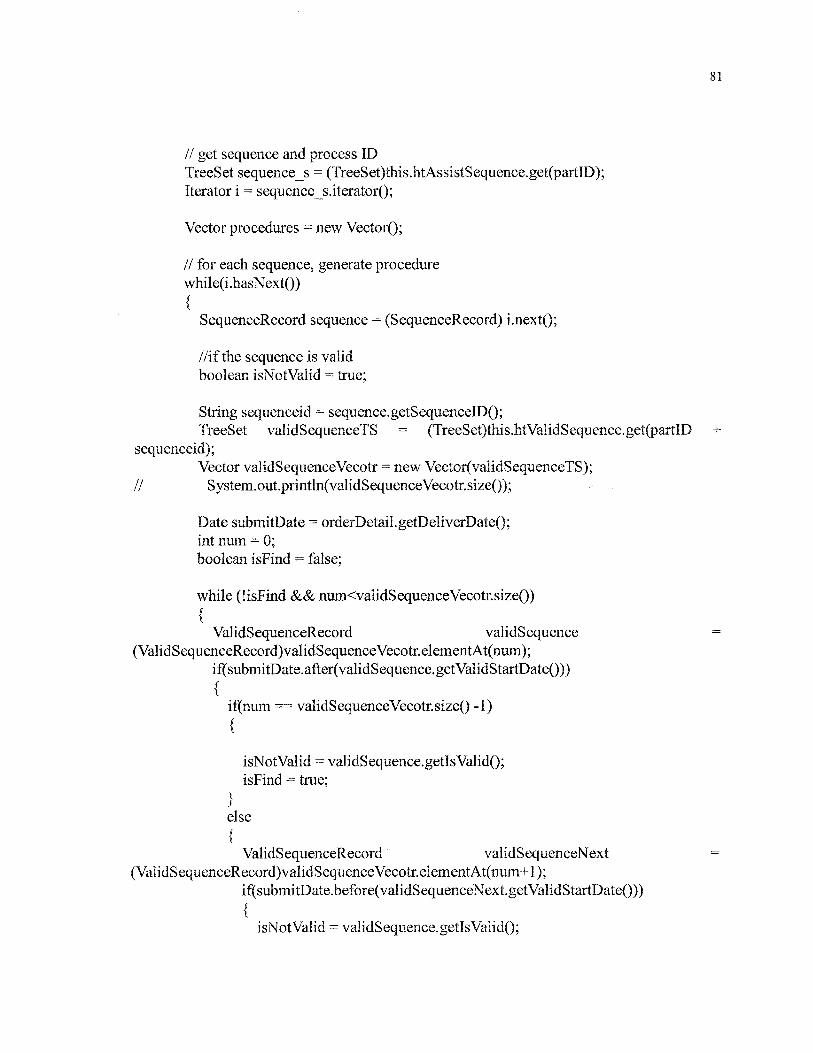
81
// get sequence and process IDTreeSet sequencers = (TreeSet)this.htAssistSequence.get(partlD);Iterator i = sequence_s.iterator();
Vector procedures = new VectorQ;
// for each sequence, generate procedurewhile(i.hasNext()){
SequenceRecord sequence = (SequenceRecord) LnextQ;
//if the sequence is validboolean isNot Valid = true;
String sequenceid = sequence.getSequencelDQ;TreeSet validSequenceTS = (TreeSet)this.htValidSequence.get(partlD +
sequenceid);Vector validSequenceVecotr = new Vector(validSequenceTS);
// Systern.out.println(validSequenceVecotr.size());
Date submitDate = orderDetail.getDeliverDateO;int num = 0;boolean isFind = false;
while (lisFind && num<validSequenceVecotr.size()){
ValidSequenceRecord validSequence =(ValidSequenceRecord)validSequenceVecotr.elementAt(num);
ifCsubmitDate.afterCvalidSequence.getValidStartDateO)){
if(num = validSequenceVecotr.sizeQ -1)
isNot Valid = validSequence.getlsValidQ;isFind = true;
}else{
ValidSequenceRecord validSequenceNext(ValidSequenceRecord)validSequenceVecotr.elementAt(num+1 );
if(submitDate.before(validSequenceNext.getValidStartDate())){
isNot Valid = validSequence.getIsValid();

82
isFInd = true;}
}//end if reach end
}//end if after the current datenum = num + 1 ;
}//end while
if(isNotValid){System.out.println(logDate.toString()+ff:The process is not in the valid
period.\r\nff);}
if(!isNotValid){
/*//get work procedure infomationString workProcedurelD = sequence.getWkProcedurelDQ;WorkingProcedureRecord wkProcedure =
(WorkingProcedureRecord)this.htWorkProcedure.get(partlD + workProcedurelD);String workcenterlD = wkProeedure.getShopIDQ;
// get produceable tableString sequencelD = sequence.getSequencelDQ;ProduceableTimeRecord produceable =
(ProduceableTimeRecord)this.htProduceableTime.get(partlD + sequencelD +workcenterlD);*/
//get produceable table, newProduceableTimeRecord produceable = null;String workcenterlD = null;
String sequencelD = sequence.getSequencelDQ;Hashtable produceableWorkcenter =
(Hashtable)this.htProduceableTime.get(partID + sequencelD);if(produceableWorkcenter == null)
{System.out.println(logDate.toString()+ff:Routing
Table :RoutingId=ff+sequenceID+ff:There is no corresponding workcenter in theProducibleTime Table .\r\nw);
}else

83
Enumeration workeenters = produceableWorkcenter.keysQ;boolean isFind2 = false;while(workcenters.hasMoreEleiments() && !isFind2){
workcenterlD = (String)workcenters.nextElement();TreeSet workeenterlnfo =
(TreeS et)produceableWorkcenter. get(workcenterlD) ;Vector v Workeenterlnfo = new Vector( workeenterlnfo);
int num2 = 0;boolean isInThisShop = false;boolean isNotValid2 = true;
while(!isInThisShop && num2<vWorkcenterInfo.size()){
ProduceableTimeRecord currentRecord =(ProduceableTimeRecord)vWorkcenterInfo.get(num2);
if(num2 == vWorkcenterlnfo.sizeQ - 1){
if(!orderDeliverDate.before(currentRecord.getValidStartDate())){
produceable = currentRecord;isNotValid2 = currentRecord.getisValidQ;isInThisShop = true;
}else{
isInThisShop = false;}//end if the deliver date is after the last record's begin date
}else{
ProduceableTimeRecord nextRecord =(ProduceableTimeRecord)vWorkcenterInfo.get(num2 + 1);
if(!orderDeliverDate.beforeCcurrentRecord.getValidStartDateO) &&orderDeliverDate.before(nextRecord.getValidStartDate()))
{produceable = currentRecord;isNotValid2 = currentRecord.getisValid();isInThisShop = true;
}else

84
isInTMsShop = false;}
}//end if reach the last recordnum2 = num2 + 1 ;
}//end while judge if in this shopif(isInThisShop && !isNotValid2){
isFind2 = true;}else
}}//end while all workcentersif(!isFind2){
produceable = null;}
}//end if produceableWorkcenter == null
// calculate the procedure's total time// WorkShopRecord workcenter =(WorkShopRecord)this.htWorkShop.get(workcenterlD);
if(workcenterID == null || produceable == null){
System.outprintln(logDate.toString()+ff :There is no correspondingWorkCenter in the WorkCenter Table .\r\n!f);
}else
WorkShopRecord workcenter(WorkShopRecord)this.htWorkShop.get(workcenterlD);
char type = (char)workcenter.getCalculateType();// System.out.println(f'flaskjdfasdjfkasdff);
double totalTime = 0.0;if(type=='U){
totalTime = produceable.getLt();totalTime = totalTime + produceable.getAbundantTimeO;
}else if(type == 'S')

85
totalTime = produceable.getStQ * number;totalTime = totalTime + produceable.getAbundantTimeQ;
}else{
//throw newZRException(CErrorNumber.CALCULATE_TYPE ERROR);
System.out.println(logDate.toString()+":Calculate Type error.\r\nff);}
// System.out.println(ffflaskjdfasdjfkasdff);ZRWorkProcedure pro = new
ZRWorkProcedureCorder.getOrderlDO^rderDetail.getDivideNOQ^rder.getPartlDCorderDetailgetQuantity()5sequence.getWkProeediireID()3seqiience.getSeqiienceID()?sequence.getSequence()?workcenterID5totalTime);// System.out.println(ffflaskjdfasdjflcasdff);
procedures.add(pro);// System.out.println(ffflaskjdfasdjfkasdff);
else{
//the sequence is not valid}
}//end search in all sequence belong to this order//calculate LFT and ESTDate lft = orderDetailgetLftDateQ;Date est = orderDetail.getEstDateQ;int n = procedures.sizeQ;if(procedures.size() == 0){// throw new ZRException(CErrorNumber.PROCEDURESPREADFAILED);System.out.println(logDate.toString()+":Procedure spread error.\r\n");
}else
ZRWorkProcedure pro = (ZRWorkProcedure)procedures.get(O);pro.setEST(est);for(intj = l ; j<n ; j++ )
{ZRWorkProcedure pro__prev = (ZRWorkProcedure)procedures.get(j-l);ZRWorkProcedure pro_curr = (ZRWorkProcedure)procedures.get(j);long prevjime = pro_prev.getEST().getTime();prev___time = prevjime + (int)(pro__prev.getTotalTime()*1000);
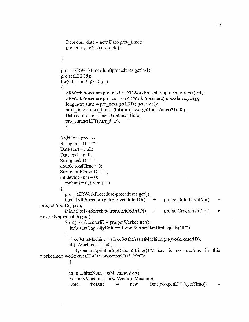
86
Date curr_date = new Date(prev_time);pro_curr.setEST(curr_date);
pro = (ZRWorkProcedure)procedures.get(n-l);pro.setLFT(lft);for(int j = n-2; j>=0; j--){
ZRWorkProcedure projQext = (ZRWorkProcedure)procedures.get(j+l);ZRWorkProcedure provenir = (ZRWorkProcedure)procedures.get(j);long nextjime = pro_nextgetLFT().getTime();nextjime = nextjime - (int)(pro_next.getTotalTime()*1000);Date curr_date = new Date(next_time);pro_ciirr.setLFT(curr_date);
//add load processString unitlD =ffff;Date start = null;Date end = null;String taskID = î!îf;double totalTime = 0;String mnfOrderlD =fl";int devideNum = 0;
for(intj = O;j<n;j++)
{pro = (ZRWorkProcedure)procedures.get(j);this.htAllProcedure.put(pro. getOrderID() + pro. getOrderDi vidNo() +
pro.getProcID()3pro);this.htProForSearch.put(pro.getOrderID() + pro.getOrderDividNo() +
pro.getSequenceID()5pro);String workcenterlD = pro.getWorkcenter();
if(this.intCapacityUnit == 1 && this.strPlanUint.equals(?fR")){
TreeSet tsMachine = (TreeSet)htAssistMachine.get(workcenterlD);if(tsMachine==null) {
System.out.println(logDate.toString()+ff:There is no machine in thisworkcenter: workcenterID=ff+workcenterID+" .\r\nff);
int machineNum = tsMachine. sizeQ;Vector vMachine = new Vector(tsMachine);Date theDate = new Date(pro.getLFT().getTime()
87
(pro.getLFT().getTime())%(24*3600* 1000) - this.TIME_ZONE*3600* 1000);Date lastDay = new Date(this.datePlanBase.getTime() +
this.intPlanDucration*24*3600* 1000);if(theDate.after(lastDay) || theDate.equals(lastDay))
{theDate = new Date(lastDay.getTime() - 24*3600*1000);
//get the latest unit, if standard capacity lower than current loadEquipmentRecord lastMachine
(EquipmentRecord)vMachine.get(machineNum -1 );String lastMachinelD = lastMachine.getEquipmentlDQ;ZRMachine lastZRMachine =
(ZRMachine)this.htMachine.get(lastMachinelD);MachineDay lastMachineDay =
(MachineDay)((Hashtable)lastZRMachine.getDayHT()).get(lastMachineID +theDate.toStringO);
if(lastMachineDay. getCurrentLoadQ >lastMachineDay.getStandardCapacityO)
{//add the procedure to the first unitEquipmentRecord machine = (EquipmentRecord)vMachine.get(O);String machinelD = machine.getEquipmentlDQ;ZRMachine zrMachine = (ZRMachine)this.htMachine.get(machinelD);MachineDay machineDay
(MachineDay)((Hashtable)zrMachine.getDayHT()).get(machineID +theDate.toStringO);
pro.setMachine(machineID);Integer seq = new IntegerCpro.getSequenceQ);String sequence = seq.toStringQ;String temp = ffff;for(int nu = 0; nu< 5-sequence.length();nu++){
temp = temp + "0";}sequence = temp + sequence;
String strTaskID = pro.getPartsID() + "_" + pro.getMachine() + "_" +ZRComm.date2String(pro.getLFT()) + sequence;
pro.setTasklD(strTasklD);
machineDay.addLoad(pro);

//out put the infomationunitlD = machinelD;start = machineDay.getCalDateQ;end = new Date(machineDay.getCalDate().getTime() + 24*3600*1000 -1);taskID = "undefined";totalTime = pro.getTotalTimeQ;mnfOrderlD = orderlD;devideNum = 0;
}else{
boolean flag = true;Enumeration eMachine = vMachine.elementsQ;while(eMachine.hasMoreElements() && flag){
EquipmentRecord machine(EquipmentRecord)eMachine.nextElement();
String machinelD = machîne.getEquîpmentlDQ;ZRMachine zrMachine = (ZRMachine)this.htMachine.get(machinelD);MachineDay machlneDay
(MachineDay)((Hashtable)zrMachine.getDayHT()).get(machineID + theDateioString())^if(machlneDay.getStandardCapacity() >= machineDay.getCurrentLoad())
pro. setMachine(machineïD) ;Integer seq = new Integer(pro.getSequence());String sequence = seq.toStringQ;String temp = fffî;for(int nu = 0; nu< 5-sequencelength();nu++){
temp = temp + "0";}sequence = temp + sequence;
String strTaskID = pro.getPartsIDQ + "__" + pro.getMachineQ + ff__ff +ZRComm.date2String(pro.getLFT()) + sequence;
pro.setTasklD(strTasklD);
machineDay addLoad(pro) ;
unltID = machinelD;start = machineDay. getCalDateQ;end = new Date(machineDay.getCalDate().getTime() + 24*3600*1000
89
taskID = "undefined";totalTime = pro.getlbtalTimeQ;mnfOrderlD = orderlD;devideNum = 0;
flag = false;}else{
flag = true;
}else if(this.intCapacityUnit = 1 && this.strPlanUint.equals("W")){
ZRWorkcenter workcenter(ZRWorkcenter)this.htWorkCenter.get(workcenterlD);
if ( workcenter == null) {System.out.println(logDate.toString()+":There is no corresponding
workcenter. \r\n");}Date theDate = new Date(pro.getLFT().getTime()
(pro.getLFT().getTime())%(24*3600*1000) - this.TIME^ZONE*3600*1000);
Date lastDay = new Date(this.datePlanBase.getTime() +this.intPlanDucration*24*360Q* 1000);
if(theDate.after(lastDay) || theDate.equals(lastDay))
{theDate = new Date(lastDaygetTime() - 24*3600*1000);
}// System.out.println(theDate.toString() + pro.getLFT());
Hashtable htWorkcenterDay = workcenter.getDayHT();
Integer seq = new Integer(pro.getSequenceQ);String sequence = seq.toStringQ;String temp = lfff;for(int nu = 0; nu< 5-sequence.length();nu++)
{temp = temp + "0";
}sequence = temp + sequence;

90
String strTaskID = pro.getPartsIDQ + "_" + pro.getWorkcenterQ + "__" +ZRComm.date2String(pro.getLFT()) + sequence;
pro.setTasklD(strTasklD);
(( WorkcenterDay)htWorkcenterDay. get(workcenterID +theDate.toString())).addLoad(pro);
//out put the infomationunitID = workcenterlD;start = ((WorkcenterDay)htWorkcenterDay.get(workcenterID +
theDate.toString())).getCalDate();end = new Date(start.getTIme() + this.intCapacityUnit*24*3600*1000 -1);taskID = "undefined";totalTime = pro.getTotalTimeQ;mnfOrderlD = orderlD;devideNum = 0;
}else if(this.intCapacityUnit == 7 && this.strPlanUint.equals("R")){
TreeSet tsMachine = (TreeSet)htAssIstMachine.get(workcenterlD);if (tsMachine == null) {System.out.println(logDate.toString()+":There is no machine in this
workcenter: workcenterID=ff+workcenterID+" .\r\n");}int machineNum = tsMachine.sizeQ;Vector vMachine = new Vector(tsMachine);long weekNum = (pro.getLFT().getTime()
this.datePlanBase.getTime())/(this.intCapacityUnit*24*3600*1000);Date theDate = new Date(this.datePlanBase.getTime() + weekNum *
(this.intCapacityUnit*24*3600* 1000));
Date lastDay = new Date(this.datePlanBase.getTime() +this.intPlanDucration*24*3600* 1000);
if(theDate.after(lastDay)){
weekNum = thisintPlanDucration/this.intCapacityUnit;theDate = new Date(this.datePlanBase.getTime() + weekNum *
(this.intCapacityUnit*24*3600* 1000));
//get the latest unit, if standard capacity lower than current loadEquipmentRecord lastMachine
(EquipmentRecord)vMachine.get(machineNum -1 );String lastMachinelD = lastMachine.getEquipmentlDQ;

91
ZRMachine lastZRMachine =(ZRMachine)this.htMachineWeek.get(lastMachinelD);
MachineWeek lastMaehineWeek =(MacMneWeek)((Hashtable)lastZRMacMne.getWeekHT()).get(lastMachineID +theDate.toStringO);
if(lastMachineWeek.getCurrentLoad() >lastMachineWeek.getStandardCapacityO)
{//add the procedure to the first unitEquipmentRecord machine = (EquipmentRecord)vMachine.get(O);String machinelD = machine.getEquipmentlDQ;ZRMachine zrMachine =
(ZRMachine)this.htMachineWeek.get(machinelD);MachineWeek machineWeek =
(MachineWeek)((Hashtable)zrMachine.getWeekHT()).get(machineID +theDate.toStringO);
pro.setMachineCmachinelD);Integer seq = new Integer(pro.getSequence());String sequence = seq.toStringQ;String temp = fHf;for(int nu = 0; nu< 5-sequence.length();nu++)
{temp = temp + "0";
}sequence = temp + sequence;
String strTaskID = pro.getPartsIDQ + ff_ff + pro.getMachineQ + "__" +ZRComm.date2String(pro.getLFT()) + sequence;
pro.setTasklD(strTasklD);
machine Week.addLoad(pro);
//out put the infomationunitlD = machine. getEquipmentlDQ;start = machineWeek. getCalDateQ;end = new Date(start.getTime() + this.intCapacityUnit*24*3600*1000 -1);taskID = "undefined";totalTime = pro.getTotalTimeQ;mnfOrderlD = orderlD;devideNum = 0;

92
else{
boolean flag = true;Enumeration eMachine = vMachine.elementsQ;while(eMachine.hasMoreElements() && flag){
EquipmentRecord machine =(EquipmentRecord)eMachine.nextElementQ;
String machinelD = machine.getEquipmentID();ZRMachine zrMachine =
(ZRMachine)this.htMachineWeek.get(machinelD);MachineWeek machineWeek =
(Machine Week)((Hashtable)zrMachine.getWeekHT()).get(machineID +theDate.toStringO);
if(machineWeek.getStandardCapacity() >=machine Week.getCurrentLoad())
{pro.setMachineCmachinelD);
Integer seq = new Integer(pro.getSequenceQ);String sequence = seq.toStringQ;String temp = "";for(int nu = 0; nu< 5-sequence.length();nu++){
temp = temp + "0";}sequence = temp + sequence;
String strTaskID = pro.getPartsIDQ + "_" + pro.getMachineQ + "Jf +ZRComm.date2String(pro.getLFT()) + sequence;
pro.setTasklD(strTasklD);machine Week.addLoad(pro);
unitID = machine.getEquipmentID();start = machine Week.getCalDate();end = new Date(start.getTime() + this.intCapacityUnit*24*3600*1000
-l);taskID = "undefined";totalTime = pro.getTotalTimeQ;mnfOrderlD = orderlD;devideNum = 0;
flag = false;}else
93
flag = true;
}else if(this.intCapacityUnit == 7 && this.strPlanUint.equals("W"))
ZRWorkcenter workcenter(ZRWorkcenter)this.htWorkCenterWeek.get(workcenterlD);
System.out.println(logDate.toString()+":There is no corresponding workcenter.\r\n");
long weekNum = (pro.getLFT().getTime()this.datePlanBase.getTime())/(this.intCapacityUnit*24*3600*1000);
Date theDate = new Date(this.datePlanBase.getTime() + weekNum *(this.intCapacityUnit*24*3600* 1000));
Date lastDay = new Date(this.datePlanBase.getTime() +this.intPlanDucration*24*3600* 1000);
if(theDate.after(lastDay)){
weekNum = this.intPlanDucration/this.intCapacityUnit;theDate = new Date(this.datePlanBase.getTime() + weekNum *
(this.intCapacityUnit*24*3600* 1000));
Hashtable htWorkcenterWeek = workcenter.getWeekHTQ;Integer seq = new Integer(pro.getSequenceQ);String sequence = seq.toString();String temp = "";for(int nu = 0; nu< 5-sequence.length();mi++)
{temp = temp + "0";
}sequence = temp + sequence;
String strTaskID = pro.getPartsID() + "_" + pro. get Workcenter () + "_" +ZRComm.date2String(pro.getLFT()) + sequence;
pro.setTasklD(strTasklD);((WorkcenterWeek)htWorkcenterWeek.get( workcenter ID +
theDate.toString())).addLoad(pro);
94
unitlD = workcenterlD;start = theDate;end - new Date(start.getTime() + thisintCapacityUnit*24*3600*1000
-i);taskID = "undefined";totalTime = pro.getTotalTime();mnfOrderlD = orderlD;devideNum = 0;
}else
}}//end add load process}}//end if the order is in the termelse{//the order is out of rangeSystem.out.println("The Order is out of range. orderID="+orderID+"\r\n");
}}//end search in all the orders
Top Related