


Languages
Pages
Legal


Safety Manual
SH 8393 EN Edition January 2018
Type 3755-1: low-noise venting over a sintered polyethylene filter disk
Type 3755-2: flanged-on threaded exhaust port
Series 3755Type 3755 Pneumatic Volume Booster
Safety Manual

2 SH 8393 EN
Definition of signal words
Hazardous situations which, if not avoided, will result in death or serious injury
Hazardous situations which, if not avoided, could result in death or serious injury
Property damage message or malfunction
Additional information
Recommended action
DANGER!
WARNING!
NOTICE!
Note
Tip

SH 8393 EN 3
Purpose of this manualThe Safety Manual SH 8393 contains information relevant for the use of the Type 3755 Pneumatic Volume Booster in safety-instrumented systems according to IEC 61508 and IEC 61511. The safety manual is intended for planners, constructors and operators of safe-ty-instrumented systems.
Risk of malfunction due to incorrect mounting, connection or start-up of the device.Refer to the Mounting and Operating Instructions u EB 8393 on how to mount the device, perform the pneumatic connections as well as start up the device.Observe the warnings and safety instructions written in the Mounting and Operating Instruc-tions EB 8393.
Further documentationThe documents listed below contain descriptions of the start-up, functioning and operation of the pneumatic volume booster. You can download these documents from the SAMSON web-site. The documents marked with an asterisk (*) are supplied with the pneumatic volume booster either in printed or electronic form.u T 8393: Data Sheetu EB 8393*: Mounting and Operating Instructions
In addition to the volume booster documentation, observe the documentation for the pneu-matic actuator, valve and other valve accessories.
NOTICE!
Note

4 SH 8393 EN
Contents
1 Scope ...........................................................................................................5General ........................................................................................................5Use in safety-instrumented systems ..................................................................5Versions and ordering data ............................................................................5Example hook-ups..........................................................................................6
2 Technical data ...............................................................................................73 Safety-related functions .................................................................................84 Mounting, connection and start-up .................................................................95 Required conditions .......................................................................................9
Selection .......................................................................................................9Mechanical and pneumatic installation ............................................................9Operation ...................................................................................................10
6 Proof testing ................................................................................................11Function testing ............................................................................................11Visual inspection to avoid systematic failure ...................................................12
7 Repairs .......................................................................................................12
SH 8393 EN 5
Scope
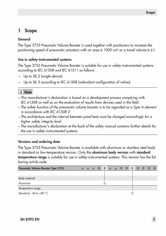
1 ScopeGeneralThe Type 3755 Pneumatic Volume Booster is used together with positioners to increase the positioning speed of pneumatic actuators with an area ≥ 1000 cm² or a travel volume ≥ 6 l.
Use in safety-instrumented systemsThe Type 3755 Pneumatic Volume Booster is suitable for use in safety-instrumented systems according to IEC 61508 and IEC 61511 as follows: − Up to SIL 2 (single device) − Up to SIL 3 according to IEC 61508 (redundant configuration of valves)
− This manufacturer's declaration is based on a development process complying with IEC 61508 as well as on the evaluation of results from devices used in the field. − The safety function of the pneumatic volume booster is to be regarded as a Type A element in accordance with IEC 61508-2. − The architecture and the interval between proof tests must be changed accordingly for a higher safety integrity level. − The manufacturer's declaration at the back of the safety manual contains further details for the use in safety-instrumented systems.
Versions and ordering dataThe Type 3755 Pneumatic Volume Booster is available with aluminum or stainless steel body in standard or low-temperature version. Only the aluminum body version with standard temperature range is suitable for use in safety-instrumented systems. This version has the fol-lowing article code:Pneumatic Volume Booster Type 3755- x x x 0 0 x x 0 0 0 0 0 0 0
Body material
Aluminum 0
Temperature range
Standard, –40 to +80 °C 0
Note

6 SH 8393 EN
Scope
Example hook-upsThe pneumatic volume booster is mounted between the positioner and actuator.
4
1
3
2
5
4
1
4
1 22
5
5
1 Positioner2 Supply pressure regulator3 Solenoid valve4 Pneumatic actuator5 Volume booster
Fig. 1: Standard connection of the pneumatic volume booster for both fail-safe positions
Fig. 2: Installation of the pneumatic volume booster with an additional solenoid valve

SH 8393 EN 7
Technical data
2 Technical data
Pneumatic volume boosterType 3755-1 Type 3755-2
Aluminum body
Flow coefficients
KVS Supply 2.5 m³/h
KVS Exhaust 2.5 m³/h
KVS Bypass 0.3 m³/h
Closed loop control
Pressure ratio: Signal to output 1:1
Response pressure Standard temperature range: 80 mbar
Pressure
Supply Max. 10 bar · Max 145 psi
Actuator Max. 7 bar · Max 101.5 psi
Signal Max. 7 bar · Max 101.5 psi
Air quality acc. to ISO 8573-1
Maximum particle size and density: Class 4Oil content: Class 3,
Pressure dew point: Class 3 or at least 10 K below the lowest ambient temperature to be expected
Connecting thread
Supply (SUP) G ¾ (optionally ¾ NPT)
Actuator/output (OUT) G ¾ (optionally ¾ NPT)
Signal (SIG) G ¼ (optionally ¼ NPT)
Exhaust port (EXH) – G 1 (optionally 1 NPT)
Safety integrity level
Use in safety-instrumented systems according to IEC 61508/IEC 61511
Suitable for use in safety-instrumented systems up to SIL 2: applies to a single deviceSuitable for use in safety-instrumented systems up to SIL 3: applies to redundant configuration of valves according to IEC 61508
Î See manufacturer's declaration at the back of this safety manual.

8 SH 8393 EN
Safety-related functions
Pneumatic volume boosterType 3755-1 Type 3755-2
Aluminum body
Degree of protection
Degree of protection provided by enclosure according to EN 60529
IP 44 1) IP 66
Compliance
Other operating parameters
Permissible ambient temperature Standard temperature range: –40 to +80 °C
Service life ≥1 x 10⁷ full strokes
Weight 2.1 kg 2.4 kg
Materials
Body Cast aluminum, powder paint coated (RAL 1019)
EN AC-43000KF according to DIN EN 1706
EN AC-43000KF according to DIN 1706 and EN AW-5083-H112 according to
DIN EN 755-3
Exhaust side Silencer with sintered polyethylene filter disk and stainless steel
retaining plate
Flanged-on threaded port made of aluminum, powder coated
(RAL 1019)
Diaphragm Standard temperature range: VMQ
Seat-plug seal VMQ
Other seals NBR
Other external parts 1.4404
1) Exhaust side facing downward or to the side
3 Safety-related functionsThe safety function of the Type 3755 Pneumatic Volume Booster is the emergency venting on demand.

SH 8393 EN 9
Mounting, connection and start-up
4 Mounting, connection and start-upRefer to Mounting and Operating Instructions u EB 8393 on how to mount, perform the pneumatic connections as well as start up the device.Only use the specified original mounting parts and accessories.
5 Required conditions
Risk of malfunction due to incorrect selection or wrong installation and operating conditions.Only use control valves in safety-instrumented systems after the necessary conditions in the plant have been fulfilled. The same applies to the mounted pneumatic volume booster.
Selection Î The volume booster's required degree of protection is observed.
Versions Degree of protection
Type 3755-1 IP 44 (exhaust side facing downward or to the side)
Type 3755-2 IP 66
Î The permissible ambient temperature from –40 to +80 °C has been observed.
Mechanical and pneumatic installation Î The pneumatic volume booster is mounted properly as described in the mounting and op-erating instructions and connected to the air supply.
Î The maximum supply pressure does not exceed 10 bar. Î The pneumatic air supply meets the instrument air specifications.
Particle size and quantity Oil content Pressure dew pointClass 4 Class 3 Class 3≤5 µm and 1000/m³ ≤ 1 mg/m³ –20 °C or at least 10 K below the lowest
ambient temperature to be expected
WARNING!
10 SH 8393 EN
Required conditions
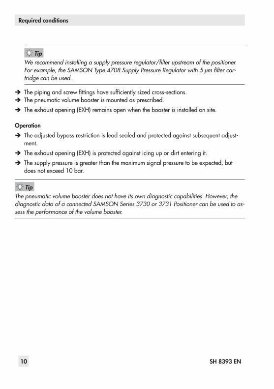
We recommend installing a supply pressure regulator/filter upstream of the positioner. For example, the SAMSON Type 4708 Supply Pressure Regulator with 5 µm filter car-tridge can be used.
Î The piping and screw fittings have sufficiently sized cross-sections. Î The pneumatic volume booster is mounted as prescribed. Î The exhaust opening (EXH) remains open when the booster is installed on site.
Operation Î The adjusted bypass restriction is lead sealed and protected against subsequent adjust-ment.
Î The exhaust opening (EXH) is protected against icing up or dirt entering it. Î The supply pressure is greater than the maximum signal pressure to be expected, but does not exceed 10 bar.
The pneumatic volume booster does not have its own diagnostic capabilities. However, the diagnostic data of a connected SAMSON Series 3730 or 3731 Positioner can be used to as-sess the performance of the volume booster.
Tip
Tip

SH 8393 EN 11
Proof testing
6 Proof testingThe proof test interval and the extent of testing lie within the operator's responsibility. The operator must draw up a test plan, in which the proof tests and the interval between them are specified. We recommend summarizing the requirements of the proof test in a check-list.
Risk of dangerous failure due to malfunction in the event of emergency (valve does not move to the fail-safe position).Only use devices in safety-instrumented systems that have passed the proof test according to the test plan drawn up by the operator.
Regularly check the safety-instrumented function of the entire SIS loop. The test intervals are determined, for example on calculating each single SIS loop in a plant (PFDavg).
Function testingRegularly check the safety function according to the test plan drawn up by the operator.
Record any faults in the pneumatic volume booster and inform SAMSON of them in writing.
1. Move the valve clearly away from the fail-safe position (e.g. set point at 50 % in control valves or to the operating position of on/off valves).
2. De-energize (e.g. 0 mA signal) the inputs at the connected devices (positioner, solenoid valve etc.).
3. Check the effect:Does the valve move to the fail-safe position within the required time?
WARNING!
Note

12 SH 8393 EN
Repairs
Visual inspection to avoid systematic failureTo avoid systematic failure, visible inspections of the pneumatic volume booster on a regular basis must be performed. The frequency and the scope of the inspection lie within the opera-tor's responsibility. Take application-specific influences into account, such as: − Corrosion (destruction primarily of metals due to chemical and physical processes) − Aging (damage caused to organic materials, e.g. plastics or elastomers, by exposure to
light and heat) − Chemical attack (organic materials, e.g. plastics or elastomer, which swell, leach out or
decompose due to exposure to chemicals)
Risk of malfunction due to the use of unauthorized parts.Only use original parts to replace worn parts.
7 RepairsOnly perform the work on the pneumatic volume booster described in u EB 8393.
Fail-safe action impaired due to incorrect repair.Service and repair work must only be performed by trained staff.
NOTICE!
NOTICE!

SH 8393 EN 13
SAMSON AKTIENGESELLSCHAFT · Weismuellerstrasse 3 · 60314 Frankfurt am Main, Germany · www.samson.de 1
Manufacturer's Declaration: V/HE-1193-3 DE-EN Changed on: 2017-11-08 Changed by: V42/Lb/V74/Hlb/V74/pmr
HERSTELLERERKLÄRUNG MANUFACTURER’S DECLARATION Für folgende Produkte For the following products
Pneumatischer Volumenstromverstärker Typ 3755-xxx000x000…
Type 3755-xxx000x000… Pneumatic Volume Booster
Hiermit wird bestätigt, dass der pneumatische Volumenstromverstärker gemäß IEC 61508 für den Einsatz in sicherheitsgerichteten Kreisen geeignet ist. Basis dieser Erklärung ist ein mit IEC 61508 konformer Entwicklungsprozess sowie die Auswertung der Ergebnisse aus dem Feldeinsatz des Gerätes.
We hereby certify that the pneumatic volume booster is suitable for use in safety-instrumented systems according to IEC 61508. This manufacturer's declaration is based on a development process complying with IEC 61508 as well as on the evaluation of results from devices used in the field.
Der pneumatische Volumenstromverstärker hat eine HFT von 0 und kann nach IEC 61511 bis SIL 2 (einzelnes Gerät, HFT = 0) und SIL 3 (Einsatz an redundant verschalteten Ventilen, HFT = 1) eingesetzt werden. Das Gerät ist nach Typ A eingestuft.
The pneumatic volume booster has an HFT of 0 and can be used up to SIL 2 (single device, HFT = 0) and SIL 3 (use on redundant configuration of valves, HFT = 1) according to IEC 61511. The device is classified as type A.
Geltungsbereich Scope Diese Erklärung gilt nur für Geräte in den Ausführungen mit Standard-Temperaturbereich, Gehäusewerkstoff Aluminium und mit Standard-Dynamikverhalten, Typ 3755-xxx000x000….
This declaration only applies to device versions with the standard temperature range, aluminum body and standard dynamic response, Type 3755-xxx000x000....
Sicherheitstechnische Annahmen Safety-related assumptions Der pneumatische Volumenstromverstärker entlüftet den Antrieb in Abhängigkeit des zwischen Steuereingang und Ausgang anliegenden Differenzdrucks. Die Luftleistung ist abhängig vom anliegenden Differenzdruck, der maximale Kvs Wert beträgt 2,5.
The pneumatic volume booster vents the actuator depending on the pressure difference between control input and output. The air capacity depends on the differential pressure in the device. The maximum Kvs coefficient is 2.5.
Sicherheitstechnische Kenndaten Safety-related data λsafe, undetected 270 FIT λsafe, undetected 270 FIT λsafe, detected 0 λsafe, detected 0 λdangerous, undetected 26 FIT λdangerous, undetected 26 FIT λdangerous, detected 0 λdangerous, detected 0 PFDavg. bei jährlicher Prüfung 0,0001 PFDavg. with annual test 0.0001 HFT (Hardware Fault Tolerance) 0 HFT (hardware fault tolerance) 0 DC (Diagnostic Coverage) siehe Diagnose DC (diagnostic coverage) See Diagnostics Gerätetyp A Device type A SFF (Safe Failure Fraction) >90 % Safe failure fraction (SFF) >90 % MTBF gesamt 385 Jahre MTBF total 385 years MTBF dangerous, undetected 4390 Jahre MTBF dangerous, undetected 4390 years

14 SH 8393 EN
SAMSON AKTIENGESELLSCHAFT · Weismuellerstrasse 3 · 60314 Frankfurt am Main, Germany · www.samson.de 2
Manufacturer's Declaration: V/HE-1193-3 DE-EN Changed on: 2017-11-08 Changed by: V42/Lb/V74/Hlb/V74/pmr
Nutzbare Gebrauchsdauer Useful lifetime – Das Gerät enthält keine alterungskritischen
Bauteile – The device does not contain any components
that are critical concerning aging.
– Gerätespezifische Instandhaltungsempfehlungen liegen vor
– Device-specific maintenance recommendations exist.
Nach IEC 61508-2 (2010) Abschnitt 7.4.9.5 können 8 – 12 Jahre angenommen werden oder ein Wert benutzt werden, der sich durch Betriebsbewährung oder anhand von Maßnahmen des Betreibers entsprechend Fußnote IEC 61508-2 (2010) Abschnitt 7.4.9.5 N3 ergibt.
According to IEC 61508-2 (2010), section 7.4.9.5, a useful lifetime of eight to twelve years can be assumed. Other values can be used based on the previous experience (proven-in-use) or based on the measures taken by the operator as described in NOTE 3 of IEC 61508-2 (2010), section 7.4.9.5.
Bestimmungsgemäße Verwendung Intended use ‒ Bedienungsanleitung EB 8393 – Mounting and Operating Instructions EB 8393
‒ Sicherheitshandbuch SH 8393 – Safety Manual SH 8393
‒ Anforderung an Instrumentenluft-Qualität ‒ Quality requirements for instrument air
Betriebsbewährtheit Proven in use ‒ Die Anforderungen IEC 61511-1 Abschnitt
11.5.3 „Anforderungen an die Auswahl von Komponenten und Teilsystemen auf Basis einer früheren Verwendung“ sind erfüllt.
– The requirements stipulated in section 11.5.3 in IEC 61511-1 (Requirements for the selection of components and sub-systems based on prior use) are met.
– Der Nachweis der Leistungsfähigkeit des Gerätes ist durch die bei der Firma SAMSON dokumentierte Felderfahrung erbracht.
– The evidence of the device's performance is supplied by the documented field experience gained by SAMSON.
– Die Verantwortung für den Einsatz in spezifischen Umgebungsbedingungen liegt beim Anwender.
– The user is responsible for the use in specific ambient conditions.
Diagnose Diagnostics Das Gerät enthält keine eigenen Vorrichtungen zur Diagnose. Die Diagnosedaten eines vorgeschalteten Stellungsreglers können jedoch zur Beurteilung der Leistungsfähigkeit des Gerätes herangezogen werden, typische Parameter sind zum Beispiel „Laufzeit“, „Totzeit“, „bleibende Regelabweichung“ des angeschlossenen Ventils. Applikationsabhängig können auch andere Parameter verwendet werden.
The device does not have its own diagnostic capabilities. However, the diagnostic data of a connected positioner can be used to assess the performance of the device. Typical parameters include the transit time, dead time and set point deviation of the connected valve. Other application-related parameters can also be used.

SH 8393 EN 15
SAMSON AKTIENGESELLSCHAFT · Weismuellerstrasse 3 · 60314 Frankfurt am Main, Germany · www.samson.de 3
Manufacturer's Declaration: V/HE-1193-3 DE-EN Changed on: 2017-11-08 Changed by: V42/Lb/V74/Hlb/V74/pmr
Voraussetzungen Requirements Die Reparaturzeit ist klein gegenüber dem mittleren Zeitintervall zwischen zwei Anforderungen. Durchschnittliche Beanspruchung in industrieller Umgebung durch Medien und Umgebungsbedingungen. Der Anwender ist für bestimmungsgemäßen Gebrauch verantwortlich.
Short mean time to repair compared to the average rate of demand. Normal exposure to industrial environment and fluids. The user is responsible for ensuring that the device is used as intended.
SAMSON AG SAMSON AG
ppa. Michael Kiener Zentralabteilungsleiter Verkauf International
i.V. Dirk Hoffmann Zentralabteilungsleiter Entwicklungsorganisation
Head of Central Department International Sales
Head of Central Department R&D Organization

SAMSON AG · MESS- UND REGELTECHNIKWeismüllerstraße 3 · 60314 Frankfurt am Main, GermanyPhone: +49 69 4009-0 · Fax: +49 69 [email protected] · www.samson.de SH 8393 EN 20
18-0
4-11
· En
glish
Top Related