


Languages
Pages
Legal


Abstract— This paper presents the design, construction and
tests of a two-stage traveling-wave thermoacoustic electricity
generator. The engine designed has two stages with a Linear
Alternator connected in between two points having equal but
out of phase acoustic pressure amplitudes. The connection of
Linear Alternator in this configuration allows it to be run by
the effect of acoustic pressure on both sides and work in a
"push-pull" mode. Pressurized helium at 28 bar is used as
working gas and operating frequency is 54.68 Hz. In the
experiments, a maximum generated electricity and thermal-to-
electric efficiency of 48.6 W and 2.7% are obtained,
respectively, when the temperature difference across the
regenerator reaches 300˚C at 30.8 Ω load resistance. The
research results shown in this paper demonstrate that two
identical half-wave length stages can run a linear alternator in
“push-pull” mode.
Index Terms— Electricity generator, push-pull,
thermoacoustic, traveling wave
I. INTRODUCTION
ay by day, power demand rises all over the world. In
the last decades, a lot of environmental impacts have
been found and proven as caused by the power
generation technologies. This creates a thinking approach
towards clean and environmentally friendly technologies.
Thermoacoustic power generation technology could be
considered as one of such technologies.
The working principle of thermoacoustic devices is based
on a thermoacoustic effect which enables producing sound
waves from thermal energy, or vice-versa. Thermoacoustic
devices are generally described as acoustic resonators filled
with a gas as a working fluid and containing a porous
medium (regenerator) with heat source and heat sink (heat
exchangers) adjacent to it. The gas inside the resonance tube
(within the porous medium limits) will undergo a
thermodynamic cycle somewhat similar to the Stirling cycle.
In thermoacoustic engine, the working gas absorbs heat from
high temperature side of the porous medium and rejects heat
to the low temperature side while producing work in the
form of sound oscillations as an output.
Manuscript received March 6, 2016; revised April 16, 2016. This work
was supported in part by the Human Capacity Development Program
(HCDP) sponsored by Kurdistan regional government (A. Hamood) and in
part by the Royal Society Industry Fellowship (A.J. Jaworski)
Ahmed Hamood is with the Faculty of Engineering, University of
Leeds, Leeds LS2 9JT, UK; (email: [email protected]).
Xiaoan Mao is with the Faculty of Engineering, University of Leeds,
Leeds LS2 9JT, UK; (email: [email protected]).
Artur J. Jaworski, the corresponding author, is with the Faculty of
Engineering, University of Leeds, Leeds LS2 9JT, UK; (email:
Looped tube thermoacoustic engine is one of the simplest
traveling wave configurations and consists of long resonator
(one or more wave lengths) which contains the regenerator
unit and the Linear Alternator. Investigations of a looped
tube thermoacoustic system have been done by Sakamoto et
al. (2006, 2012). These investigations have been done on a
combined thermoacoustic engine and refrigerator. Using air
as a working gas, the system gave a cooling power at cooling
efficiency of about 0.15 W and 0.13%, respectively. They
subsequently improved performance to reach 0.8 W of
cooling power and 1.5% of cooling efficiency, by using a
mixture of helium and argon (50:50) instead of air.
The looped engine configuration has also been used in
SCORE project. Thermoacoustic engine was found to be
able to convert waste heat from the cooking stove to
electricity. The engine has been made of commercially
available materials and air at atmospheric pressure has been
used as working fluid (Yu et al., 2012). The simulated
efficiencies of thermal to acoustic, acoustic to electric and
thermal to electric conversion were 4.6%, 53% and 2.4%,
respectively producing electricity of 8 W. Abdoulla et al.
(2013) subsequently improved the performance of this
engine by adding a resonance tube as a branch to connect the
alternator to the loop. The efficiencies have been improved
to be 23%, 59.7% and 3.5% (thermal to acoustic, acoustic to
electricity, and thermal to electricity, respectively). The
generated electricity has been increased to reach 13 W.
Abduljalil et al. (2009) constructed a looped tube TA
engine that has a ceramic regenerator with fine square
channels instead of the conventional stainless steel mesh
core. The maximum measured acoustic power was about 26
W. Abduljalil et al. (2009) continued their work with some
improvements and the acoustic power reached 34 W.
The multi-stage thermoacoustic engines were proposed to
produce more power whenever there is enough supply of
heat to be used. It was also found that the multi-stage TA
engines are a solution to provide a low onset temperature
(Chen, 2012). Multi-stage engines have been pioneered by
de Blok (2010, 2012). Basically, they have low acoustic loss
because of lower acoustic dissipation in the resonance and
feedback loop. The identical multiple stages have been
presented as feasible from the construction point of view
because of having identical components per stage. The name
“self-matching” indicates that each stage has an independent
power extractor. From the losses point of view, it is better to
design a self-matching engine in order to avoid high power
spots and minimize losses. Four novel TA four-stage engines
have been presented by de Blok (2010). All the engines have
four power extraction points with productivity ranging from
several watts to 1.64 kW at heat to electricity efficiency no
more than 8.2%.
Two-Stage Thermoacoustic Electricity
Generator for Waste Heat Recovery
Ahmed HAMOOD, Xiaoan MAO, Artur J. JAWORSKI
D
Proceedings of the World Congress on Engineering 2016 Vol II WCE 2016, June 29 - July 1, 2016, London, U.K.
ISBN: 978-988-14048-0-0 ISSN: 2078-0958 (Print); ISSN: 2078-0966 (Online)
WCE 2016

Some efforts towards a two-stage engine with one linear
alternator have been undertaken as an outgrowth of SCORE
project. Abdoulla et al. (2012) used DeltaEC to numerically
design a two stage TA engine working as an electricity
generator. The model gave encouraging results of 6%
thermal to electricity efficiency and generating 130 W of
electric power. Chen et al. (2012) built two engines: one
driven by propane burner and the other by wood burner. The
propane driven TA engine generated 15 W of electricity and
the wood burner one produced 22.7 W. Both have used a
low efficiency alternator. Kang et al. (2015) experimentally
generated 204 W using a two-stage thermoacoustic looped
engine with two loudspeakers. The engine found to be able
to run with thermal to electric efficiency up to 3.43%.
This paper presents the experimental results of a heat
driven thermoacoustic electricity generator. The system
design, parts specifications and the experimental set-up will
be presented first. Then the experimental results will be
compared to the theoretical results which have been
predicted using DeltaEC modelling tool.
II. SYSTEM CONFIGURATION
A. Overview
The current system is a one wave length thermoacoustic
engine. The engine design has two stages with a Linear
Alternator connected in between at two points having equal
but out of phase acoustic pressure amplitudes. The
connection of Linear Alternator in this configuration allows
it to be run by the effect of acoustic pressure on both sides
and work in a "push-pull" mode. This configuration allows
the engine to have two power extraction points. The two
power extraction points help to avoid high power spots and
allow the stages to act as self-matching. The self-matching
stages have the same identical acoustic pressure and volume
flow rate amplitudes but which are out of phase. It means
that each of two identical points on the two stages have the
same acoustic pressure and volumetric flow velocity
amplitude but shifted 180º in phase. This connection
increases the system efficiency by increasing the power
output and decreases the acoustic losses.
B. Modeling
To verify the idea explained in the previous section, a
model has been constructed using DeltaEC. The DeltaEC
shooting method showed that it was unable to run two
identical stages as expected. The two identical stages when
each has a power extraction point should have the same
thermal and acoustical performance and this is what the
shooting method failed to follow. The modelling has been
done as half of the engine which is one stage and the other
stage has been represented as a self-excited flow at the other
side of the linear alternator.
Each thermoacoustic engine stage consists of a
thermoacoustic core followed by a branch to the linear
alternator and finally there is a long feedback tube. The total
length of the engine is one wave length and each stage is
exactly half wave length.
C. Experimental Setup
The thermoacoustic engine loop is 16 m long and uses
helium at 28bar as working gas, it is illustrated in Fig 1. The
thermoacoustic core consists of ambient heat exchangers
AHX, regenerator, hot heat exchanger HHX, thermal buffer
tube TBT and the secondary ambient heat exchanger
2ndAHX. The core has a diameter of 10cm, reduced to
7.5cm at the end of the TBT and the 2ndAXH. The core
layout is shown in Fig. 2. The core is arranged vertically; the
AHX at the top and the 2ndAHX at the bottom. This has
been experimentally verified to enhance the temperature
distribution in the regenerator and the TBT and reduce the
onset temperature (Liu et. al. 2002, Abduljalil et. al. 2009).
Fig. 1. Photograph of the two-stage thermoacoustic engine
Fig. 2. (a) Thermoacoustic core (b) Ambient and secondary heat
exchangers (c) Hot heat exchanger
The heat exchangers used in the model are parallel plate
heat exchangers having a plate spacing of 1mm and 65%
blockage ratio. The heat exchangers of this project have
been fabricated using wire cutting. The wire cutting is to
form tiny channels through a block of metal to form cross-
(b) AHX
(c) HHX (a)
Proceedings of the World Congress on Engineering 2016 Vol II WCE 2016, June 29 - July 1, 2016, London, U.K.
ISBN: 978-988-14048-0-0 ISSN: 2078-0958 (Print); ISSN: 2078-0966 (Online)
WCE 2016
flow heat exchangers. The channels are 1mm wide leaving
0.5mm fins in between, as shown in Fig 2. Firstly, it was
planned to use a simulated exhaust gases of 6.0L internal
combustion engine as heat source. Unfortunately, we weren’t
able to do so for a laboratory limitation. Cartridge heaters
have been used instead. The heaters were at a maximum
power of 900W each stage. The ambient heat exchangers are
water cooled to keep them at low temperature to maintain
temperature difference on the hot and cold sides of the
regenerator.
The AHX is of 30mm length and fabricated out of
Copper. It is placed at the top of the thermoacoustic core. It
consists of seven channels on the helium side and eight on
the cooling water side. The regenerator is located below the
AHX. It consists of 75mm thick stack of woven wire
stainless steel screen punched holder with a diameter of
101mm. The diameter of the screen wire is 71μm. The
calculated volume porosity and hydraulic radius are 75.85%
and 57.5μm respectively. The HHX fabricated out of low
carbon steel. It is 40 mm long and follows the regenerator. It
has five channels on the helium.
The HHX has two collars having inner and outer diameter
identical to 4” pipe of schedule40. These collars are to
prevent damaging the tiny channel from damaging by the
welding heat as it will be welded to a pipe and reducers to
form the hot heat exchanger assembly. The thermal buffer
tube TBT located between the HHX and the 2ndAHX
consists of three parts: 4” diameter pipe, 4”-3” reducer, and
3” diameter pipe. The two pipes are 30mm long. The
reducer of the TBT helps to suppress the Rayleigh
streaming. The 2ndAHX is similar in shape and material to
the AHX but it is 20mm long and 3” diameter. It has five
channels on the helium side and six channels on the cooling
water side.
There is a 100mm long pipe connecting the AHX to the T-
branch. The T-branch is leading to a branch and a trunk. The
branch is the link between the loop and the linear alternator.
The trunk is 7.3m long feedback loop. The feedback loop
consists of 7.05m long pipe having a diameter of 1.5” and
0.25m long pipe having a diameter of 1”. The dimensions
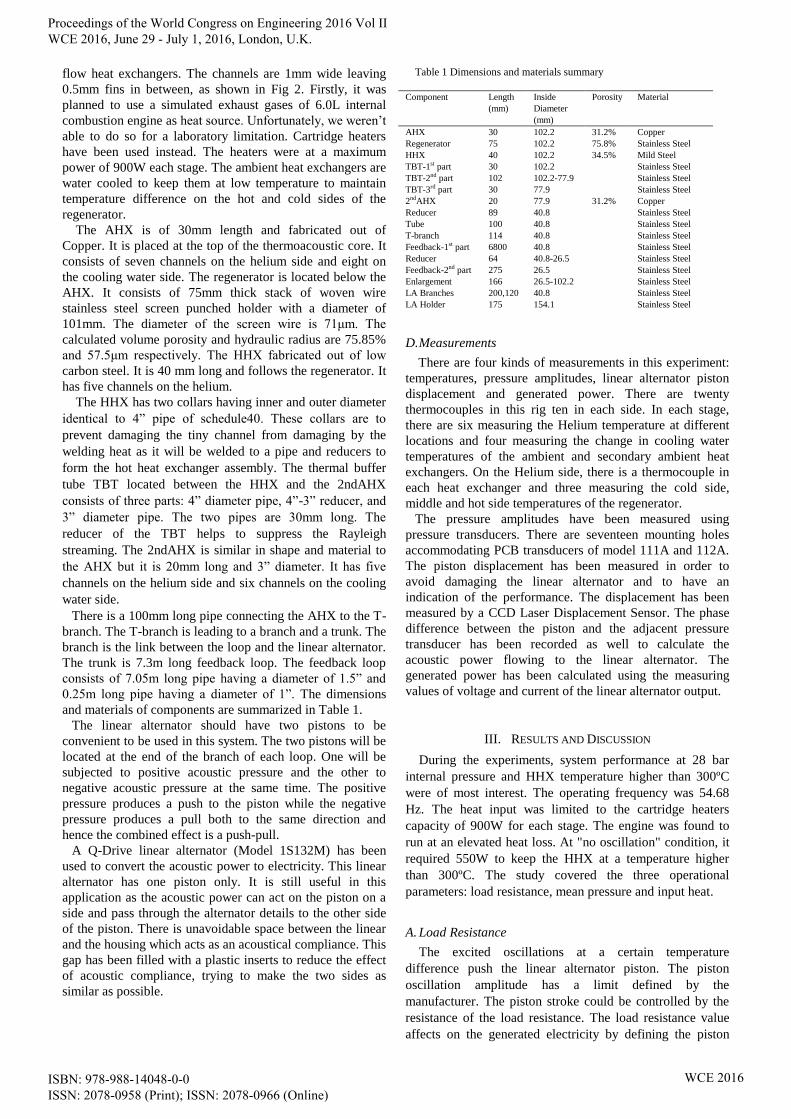
and materials of components are summarized in Table 1.
The linear alternator should have two pistons to be
convenient to be used in this system. The two pistons will be
located at the end of the branch of each loop. One will be
subjected to positive acoustic pressure and the other to
negative acoustic pressure at the same time. The positive
pressure produces a push to the piston while the negative
pressure produces a pull both to the same direction and
hence the combined effect is a push-pull.
A Q-Drive linear alternator (Model 1S132M) has been
used to convert the acoustic power to electricity. This linear
alternator has one piston only. It is still useful in this
application as the acoustic power can act on the piston on a
side and pass through the alternator details to the other side
of the piston. There is unavoidable space between the linear
and the housing which acts as an acoustical compliance. This
gap has been filled with a plastic inserts to reduce the effect
of acoustic compliance, trying to make the two sides as
similar as possible.
Table 1 Dimensions and materials summary
Component Length
(mm)
Inside
Diameter
(mm)
Porosity Material
AHX 30 102.2 31.2% Copper
Regenerator 75 102.2 75.8% Stainless Steel
HHX 40 102.2 34.5% Mild Steel
TBT-1st part 30 102.2 Stainless Steel
TBT-2nd part 102 102.2-77.9 Stainless Steel
TBT-3rd part 30 77.9 Stainless Steel
2ndAHX 20 77.9 31.2% Copper
Reducer 89 40.8 Stainless Steel
Tube 100 40.8 Stainless Steel
T-branch 114 40.8 Stainless Steel
Feedback-1st part 6800 40.8 Stainless Steel
Reducer 64 40.8-26.5 Stainless Steel
Feedback-2nd part 275 26.5 Stainless Steel
Enlargement 166 26.5-102.2 Stainless Steel
LA Branches 200,120 40.8 Stainless Steel
LA Holder 175 154.1 Stainless Steel
D. Measurements
There are four kinds of measurements in this experiment:
temperatures, pressure amplitudes, linear alternator piston
displacement and generated power. There are twenty
thermocouples in this rig ten in each side. In each stage,
there are six measuring the Helium temperature at different
locations and four measuring the change in cooling water
temperatures of the ambient and secondary ambient heat
exchangers. On the Helium side, there is a thermocouple in
each heat exchanger and three measuring the cold side,
middle and hot side temperatures of the regenerator.
The pressure amplitudes have been measured using
pressure transducers. There are seventeen mounting holes
accommodating PCB transducers of model 111A and 112A.
The piston displacement has been measured in order to
avoid damaging the linear alternator and to have an
indication of the performance. The displacement has been
measured by a CCD Laser Displacement Sensor. The phase
difference between the piston and the adjacent pressure
transducer has been recorded as well to calculate the
acoustic power flowing to the linear alternator. The
generated power has been calculated using the measuring
values of voltage and current of the linear alternator output.
III. RESULTS AND DISCUSSION
During the experiments, system performance at 28 bar
internal pressure and HHX temperature higher than 300ºC
were of most interest. The operating frequency was 54.68
Hz. The heat input was limited to the cartridge heaters
capacity of 900W for each stage. The engine was found to
run at an elevated heat loss. At "no oscillation" condition, it
required 550W to keep the HHX at a temperature higher
than 300ºC. The study covered the three operational
parameters: load resistance, mean pressure and input heat.
A. Load Resistance
The excited oscillations at a certain temperature
difference push the linear alternator piston. The piston
oscillation amplitude has a limit defined by the
manufacturer. The piston stroke could be controlled by the
resistance of the load resistance. The load resistance value
affects on the generated electricity by defining the piston
Proceedings of the World Congress on Engineering 2016 Vol II WCE 2016, June 29 - July 1, 2016, London, U.K.
ISBN: 978-988-14048-0-0 ISSN: 2078-0958 (Print); ISSN: 2078-0966 (Online)
WCE 2016

stroke and the values of voltage and current. Fig 3 shows the
predicted and experimental results of the output electric
power as a function of the load resistance. In the
experiments, a maximum generated electricity of 48.6 W
was obtained at 30.8 Ω load resistance.
Fig. 3. The effect of load resistance on the electric power output.
B. Heat Input
It is obvious that the electricity generation of the engine is
directly related to the heat input. The heat input experiments
ranged from the maximum limit of 900 W to the minimum
input that maintain the oscillations of 600W, all at a load
resistance of 42.7Ω. Fig. 4 shows the predicted and
experimental results of the generated electric power as a
function of the heat input. The temperature difference across
the regenerator hasn’t changed a lot by reducing the heat
input from 900 W to 600 W. The main reason behind, is that
reducing the heat input has damped the oscillations and
hence reduced the heat transferred due to the thermoacoustic
effect, as shown in Fig. 5. In this figure, the piston
displacement is an example to indicate the oscillation
damping.
Fig. 4. Computational and experimental output electrical power as a
function of Heat input.
Fig. 5. Computational and experimental temperature difference across the
regenerator and piston stroke as a function of load resistance.
C. Mean Pressure
The mean pressure has been studied from the maximum
allowable pressure of 28 bar to the lowest pressure that runs
the engine of 12 bar. The decrease in mean pressure has
found to damp the oscillations, and hence decrease the
generated power, pressure amplitudes, piston stroke and
drive ratio. Fig 6 show the system performance at 900 W
and 42.7 Ω.
Fig. 6. Computational and experimental generated electricity as a function
of load resistance.
D. Best Performance
After studying all the three operational parameters, the
best performance of this thermoacoustic engine was at 30.8
Ω, 900 W heat input and mean pressure of 28 bar. In the
experiments, a maximum generated electricity and heat-to-
electric efficiency were 48.6 W was obtained at 30.8 Ω load
resistance. The heat-to-electric efficiency was 2.7% and the
oscillation frequency was 54.68 Hz. The drive ratio of
2.26% and piston stroke of 3.77 mm. The temperature
difference across the regenerator was 300ºC. The predicated
generated electricity was 59 W leaving the agreement
between the experimental and theoretical generated power to
be 82.4%.
Fig. 7 illustrates the main design strategy. The strategy is
to design two identical stages connected in one loop. It was
targeted that the two stages have identical parts and hence
they will generate and dissipate the acoustic power
identically, as shown in Fig. 7e. The identical stages will
have the same pressure and velocity amplitudes which will
allow the connection of the linear alternator to two identical
points to work in “push-pull” mode, as shown in Fig. 7a-e.
The graph shows a good agreement between the calculated
and measured values of the pressure amplitudes and acoustic
power calculations. The only difference is around the
beginning of the stages. Clearly, the second stage has higher
pressure amplitude and acoustic power around the linear
alternator branch as the first stage has a piston and the
second stage has the back of the linear alternator as
explained in the experimental set-up.
Fig. 7a shows the calculated and measured pressure
amplitude distribution along the engine. There are two peaks
both are near the regenerators of both stages. There is a
major pressure drop at the regenerator and a minor at the
linear alternator. The major one caused by the flow
resistance at the regenerator and minor is due to power
extraction at the linear alternator.
Fig. 7b shows the distribution of volumetric velocity
along the thermoacoustic engine. Unfortunately, there is no
Proceedings of the World Congress on Engineering 2016 Vol II WCE 2016, June 29 - July 1, 2016, London, U.K.
ISBN: 978-988-14048-0-0 ISSN: 2078-0958 (Print); ISSN: 2078-0966 (Online)
WCE 2016

Fig. 7. (a) Pressure amplitude, (b) volumetric velocity, (c) acoustic
impedance, (d) phase difference angle and (e) acoustic power flow along
the engine.
velocity measurements taken in this experiments. The engine
has been designed to have the lowest volumetric flow rate at
the regenerator. The small volumetric flow velocity at the
regenerator is essential to minimize the viscous dissipation.
The effect of the temperature difference across the
regenerator clearly seen in the volumetric flow rate profile as
it has been increased with the regenerator limits from the
cold end towards the hot end. There is a volumetric flow rate
drop at the linear alternator branch caused by the power
extraction at the linear alternator.
Fig.7c is the acoustic impedance profile along the engine.
In simple words, the acoustic impedance is the pressure
amplitude divided by the volumetric flow rate. It can be seen
that the acoustic impedance is maximum at the regenerators
which is one of the design strategies. The impedance drops
until the middle of the feedback loop and increase again as
per the fluctuation of the pressure and volumetric flow rate
amplitudes.
Fig. 7d shows the phase difference between the velocity
and pressure oscillation along the engine. This graph
illustrates that the regenerator has been placed at near
traveling-wave location. It is clear that the engine needs to
be modified to have a mechanism of phase adjusting in the
feedback loop.
Fig. 7e shows the acoustic power distribution along the
engine. It is shown that the 86 W fed into the cold end of the
regenerator, and it is amplified to 147.9 W at the hot end.
The alternator extracts 33.8 W. Experimentally, both stages
produced an approximate amount of the acoustic power.
There is a discrepancy between the experimental results
and the theoretical data predicted by the model. There are
many possible reasons. There are two main reasons and
some minors.
The first main reason is that the engine runs at a huge
amount of heat loss, which is not encountered in the
theoretical model. The heat loss affects the engine
performance rather than the discrepancy between the
theoretical and experimental results only. The experiments
showed that the engine cannot maintain high temperature
difference across the regenerator as the drive ratio increases.
The main source of heat loss is that the AHX and 2nd
AHX
are in metal-to-metal contact to the HHX assembly, as they
are sealed using o-rings. This heat leak will be eliminated in
future work by replacing the o-rings with relatively low
conductivity gaskets.
The second main reason may be streaming. The
temperature gradiant across the regenerator and the elevated
mean pressure excite a superimposed type of flow usually
called streaming. This kind of flow is considered to be a
steady mass flow. This phenomenon is responsible for
dissipating energy as it involves heat transfer to the wall
within the regenerator limit (Paridaens et. al. 2013, S. Job et.
al. 2003). This effect of the streaming could be seen in Fig 8.
It is showing the temperature distribution in the regenerator
in three difference locations: cold end, middle and hot end,
at different load resistance. Theoretically, temperature
distribution across the regenerator should be linear. The
streaming effect is responsible of non-linear temperature
distribution in the graph. Another point to make here is that
the streaming/non-linear temperature distribution is worse at
higher resistance. This could be interpreted as increasing the
load resistance will increase the drive ratio. In other words,
the higher the drive ratio is the higher streaming effect will
appear. Fig. 9 and 10 show the effect of the load resistance
on the drive ratio and temperature difference across the
regenerator.
Fig. 8. Temperature distribution across the regenerator at different load
resistance.
More experiments will be done later to suppress the
streaming by placing an elastic membrane at a low
volumetric flow rate.
a
b
c
d
e
Proceedings of the World Congress on Engineering 2016 Vol II WCE 2016, June 29 - July 1, 2016, London, U.K.
ISBN: 978-988-14048-0-0 ISSN: 2078-0958 (Print); ISSN: 2078-0966 (Online)
WCE 2016

Fig. 9. Experimental drive ratio at different load resistance.
Fig. 10. Measured and calculated temperature difference across the
regenerator at different load resistance.
Two of the minor discrepancy sources are the modelling
code and the dimensions of the physical parts. The DeltaEC
modeling code is a one-dimensional linear thermoacoustic
representation that does not consider any non-linear, two
dimensional or three-dimensional effects. In experiments,
there are many of these effects. The physical parts making
the engine do not perfectly match the modeled dimensions.
The other main issue related to the physical parts is the
guessed value of the smoothness of the inner diameter of the
tubes, there isn’t a certain value.
IV. CONCLUSION AND FUTURE WORK
A thermoacoustic engine runs a linear alternator in a
“push-pull” mode, working at a frequency of 54.68 Hz, was
designed and tested in this study. The system performance
was investigated at different resistive load, mean pressure
and heat input. The maximum generated power and thermal-
to-electric efficiency of 48.6 W and 2.7% respectively, at
30.8 Ω resistive load and 28 bar mean pressure. The test of
the thermoacoustic engine showed that it needs to be
amended to reduce the heat loss and suppress the streaming.
The heat loss will be reduced by placing a gasket between
the AHX and the HHX assembly. The gasket expected to
apply heat insulation as well as pressure sealing. The
streaming will be eliminated by placing a membrane in a
suitable location.
Acknowledgment
A. Hamood would like to acknowledge the Human
Capacity Development Program (HCDP) sponsored by
Kurdistan regional government. A.J. Jaworski would like to
acknowledge Royal Society Industry Fellowship funding.
References
[1] Abdoulla K., Yu, Z. & Jaworski A.J., 2012. Design of a
Low-Cost Two-Stage Thermoacoustic Electricity
Generator For Rural Communities In Developing
Countries. In ICSV19. pp. 1–8.
[2] Abdoulla K., Kang H. & Jaworski A.J., 2013.
Travelling wave thermoacoustic electricity generator
for rural areas using a side-branch alternator
arrangement. In World Conference of Engineering.
[3] Abduljalil A.S., Yu Z. & Jaworski A.J., 2009.
Construction and Performance Characterization of the
Looped-Tube Travelling-Wave Thermoacoustic
Engine with Ceramic Regenerator. International
Journal of Engineering and Applied Sciences, 5:3,
pp.139–143.
[4] de Blok C.M., 2010. Novel 4-Stage Traveling Wave
Thermoacoustic Power Generator. In ASME 2010 3rd
Joint US-European Fluids Engineering Summer
Meeting and 8th International Conference on
Nanochannels, Microchannels, and Minichannels. pp.
1–8.
[5] de Blok C.M., 2012. Multi-Stage Traveling Wave
Thermoacoustics In Practice. In ICSV19. pp. 1–8.
[6] Ceperley P.H., 1979. A pistonlessStirling engine-The
traveling wave heat engine. J. Acoustical Soc. Am.,
66,1508-1513.
[7] Chen B., 2012. Development and Assessment of
Thermoacoustic Generators Operating by Waste Heat
from Cooking Stove. Engineering, 04(12), pp.894–
902.
[8] H. Liu, E. Luo, H. Ling, J. Wu . (2002). The Influence
of Thermal Natural Convection on a Traveling-Wave
Thermoacoustic Engine. Cryocoolers . 12 (2), 447-450.
[9] Huifang Kang, Peng Cheng, Zhibin Yu and Hongfie
Zheng, (2015). A two stage traveling-wave
thermoacoustic electric generator with loudspeakers as
alternators. Applied Energy 137 (2015) 9-17.
[10] Job J., Gusev V., Lotton P. and Bruneau, M., (2003).
Acoustic streaming measurements in annular
thermoacoustic engines. J Acoust Soc Am. 2003
Apr;113(4 Pt 1):1892-9.
[11] Paridaens R., Kouidri S., and Jerbi F., (2013).
Investigation on the generation mechanisms of acoustic
streaming in a thermoacoustic prime mover.
Cryogenics 58 (2013) 78–84
[12] Sakamoto S. & Watanabe Y., 2006. Experimental
study on resonance frequency of loop-tube-type
thermoacoustic cooling system. Acoustical Science and
Technology, 27(6), pp.361–365.
[13] Sakamoto S., Sahashi K. & Watanabe Y., 2012.
Improving Thermoacoustic System Efficiency,
Measurement of a Sound Field in the Phase Adjuster.
Proceedings of Symposium on Ultrasonic Electronics,
33, pp.215–216.
[14] Swift G., 2001. Thermoacoustic: a unifying perspective
for some engines and refrigerators Fifth draf., Los
Almos National Laboratory.
[15] Yu Z. & Jaworski A.J., 2012. Demonstrator of a
combustion driven thermoacoustic electricity generator
for remote and rural areas of developing countries. In
ICSV19. pp. 1–8.
Proceedings of the World Congress on Engineering 2016 Vol II WCE 2016, June 29 - July 1, 2016, London, U.K.
ISBN: 978-988-14048-0-0 ISSN: 2078-0958 (Print); ISSN: 2078-0966 (Online)
WCE 2016
Top Related