


Languages
Pages
Legal

TWIN-TURBINE CENTRIFUGAL COMPRESSOR
INSTALLATION AND OPERATION MANUAL
Danfoss Turbocor Compressors Inc. CSS-IOP-D01-L1-V06.0July 2010

This Page Left Intentionally Blank
Installation and Operation Manual
Table of Contents
Proprietary Notice ........................................................................................................... 5List of Changes ............................................................................................................... 6Introduction ...................................................................................................................... 9Tools ................................................................................................................................ 9Safety Summary............................................................................................................. 10
Safety Warnings ................................................................................................. 10Voltage Checks Using DC Bus Test Harness (Safety Cable) ............................ 12Voltage Checks Using DC Bus Test Harness .................................................... 12
Installation ...................................................................................................................... 19Unpacking and Inspection .................................................................................. 19Rigging Requirements........................................................................................ 19Unit Placement ................................................................................................... 19Piping Connections ............................................................................................ 21Control Wiring..................................................................................................... 24
Compressor I/O Board - Mounting Instructions ............................................. 24Control Wiring Connections .......................................................................... 24Control Wiring Connection Guidelines ................ .......................................... 25Control Wiring Details ................................................................................... 27Circuit Grounding .......................................................................................... 29Voltage-Free Contacts .................................................................................. 32
Power Wiring ...................................................................................................... 33Commissioning............................................................................................................... 35
I/O Jumper Setup and Initial Checks.................................................................. 35I/O Jumper Settings ...................................................................................... 35System Checks ............................................................................................. 38
Configuring the Compressor Using the Service Monitoring Tool ....................... 42System Requirements ................................................................................... 43Software Installation ...................................................................................... 44Monitoring Tool Installation ........................................................................... 44
Establishing a Connection.................................................................................. 51RS-232 Connection ....................................................................................... 52RS-485 Connection ....................................................................................... 52
Service Monitoring Tool Basics .......................................................................... 53Starting the Service Monitoring Tool ............ ................................................. 53Entering User Input ....................................................................................... 53Compressor Connection Manager ................................................................ 53Controlling User Access ................................................................................ 54Changing Access Codes ............................................................................... 55
Monitor w/o Connection...................................................................................... 56Using the Compressor Commissioning Wizard.................................................. 57
Chiller Control Mode ..................................................................................... 60
Danfoss Turbocor Compressors Inc. 3CSS-IOP-D01-L1-V06.0
Startup Settings ............................................................................................ 61Electronic Valve Control ................................................................................ 63Analog Output Setup ..................................................................................... 66Modbus Communications ............................................................................. 68Review and For Download Settings ............. ................................................. 69
Running Checks ................................................................................................. 73Functional Description.................................................................................................... 75
Compressor Fundamentals ................................................................................ 75Main Fluid Path ............................................................................................. 75Motor Cooling ................................................................................................ 77Inlet Guide Vanes ......................................................................................... 79
Compressor Control Overview ........................................................................... 79Motor Drive System ...................................................................................... 81Soft-Start Board ............................................................................................ 81Bearing Motor Compressor Controller ........... ............................................... 81Abnormal Conditions ..................................................................................... 83Bearing PWM Amplifier ................................................................................. 83Serial Driver .................................................................................................. 83Backplane .............. ....................................................................................... 89High-Voltage DC-DC Converter .................................................................... 90
Magnetic Bearing System .................................................................................. 91Overview ............ ........................................................................................... 91Bearing Control System ................................................................................ 91
Power Line Control and Filtering ........................................................................ 93Power Line Contactor ................................................................................... 93Power Line Filters and Line Reactor .............. ............................................... 93
Compressor Operating Modes ........................................................................... 94Analog Mode ................................................................................................. 94Chiller Mode .................................................................................................. 95Modbus Mode ............................................................................................... 95
Expansion Valve Control .................................................................................... 95Operational Maintenance Checks .................................................................................. 96
Owner's Responsibilities .................................................................................... 96Frequency of Inspections ................................................................................... 96Checking the Main Supply Voltage .................................................................... 99
Mounting Instructions .................................................................................. 107AC Line Cable Connection (From External Disconnect) ............................. 109AC Line Cable Connection (to Compressor Terminal) ................................ 109Line Side Connection .................................................................................. 111Load Side Connection ................................................................................. 111Mounting Instructions .................................................................................. 114
4 Danfoss Turbocor Compressors Inc.CSS-IOP-D01-L1-V06.0
Installation and Operation Manual
Proprietary Notice
This publication contains information proprietary and confidential to Danfoss Turbocor Compressors Inc. (DTC). This document may be reproduced and distributed provided no fee is charged, the text is not modified, and the copyright notice is included.
DTC reserves the right to make changes without notice in product or component design as warranted by evolution in user needs or advancements in engineering or manufacturing technology.
DTC has exercised its best efforts to ensure that the information contained in this manual is correct. However, no warranty of reliability or accuracy is given with respect to the information and DTC shall not be responsible or liable for the correctness or suitability of the information or for any error or omission. If you encounter any difficulty in using this manual, please forward your query to DTC or its authorized sales agent.
All brand names and product names used in this manual are trademarks, registered trademarks, or trade names of their respective holders.
For product support issues, corrections, or inquiries, contact:
Product [email protected]
Danfoss Turbocor Compressors Inc.
1769 East Paul Dirac Drive
Tallahassee, Florida 32310
USA
Telephone 1-850-504-4800
Fax 1-850-575-2126
www.turbocor.com
* Subject to change without notice.
* Danfoss Turbocor’s commitment to excellence ensures continuous product improvements.
Danfoss Turbocor Compressors Inc. 5CSS-IOP-D01-L1-V06.0
List of Changes
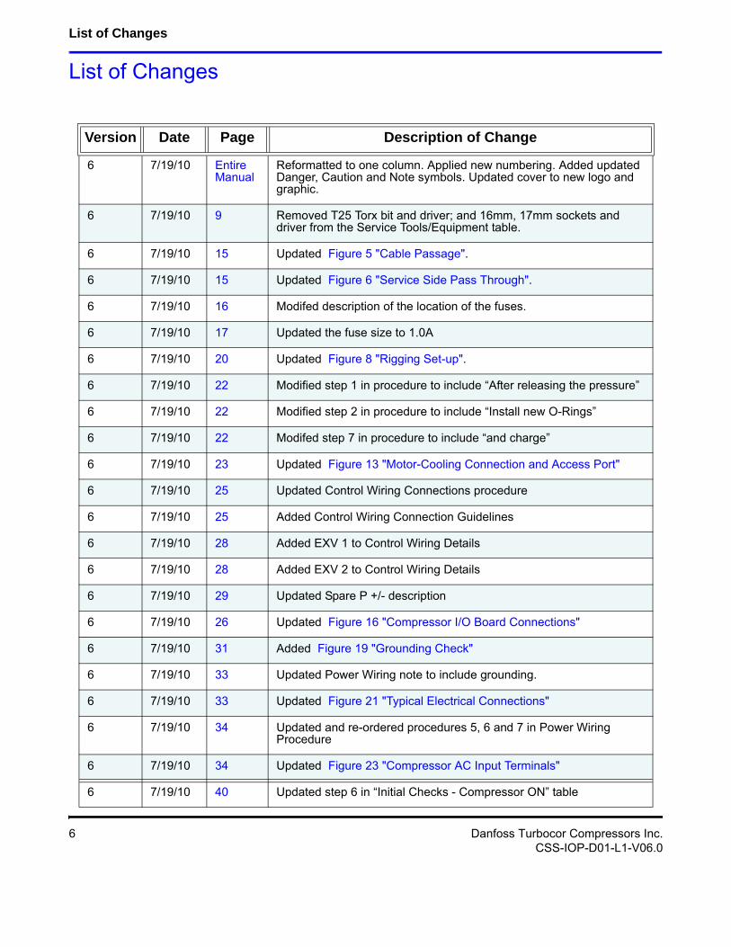
List of Changes
Version Date Page Description of Change
6 7/19/10 Entire Manual
Reformatted to one column. Applied new numbering. Added updated Danger, Caution and Note symbols. Updated cover to new logo and graphic.
6 7/19/10 9 Removed T25 Torx bit and driver; and 16mm, 17mm sockets and driver from the Service Tools/Equipment table.
6 7/19/10 15 Updated Figure 5 "Cable Passage".
6 7/19/10 15 Updated Figure 6 "Service Side Pass Through".
6 7/19/10 16 Modifed description of the location of the fuses.
6 7/19/10 17 Updated the fuse size to 1.0A
6 7/19/10 20 Updated Figure 8 "Rigging Set-up".
6 7/19/10 22 Modified step 1 in procedure to include “After releasing the pressure”
6 7/19/10 22 Modified step 2 in procedure to include “Install new O-Rings”
6 7/19/10 22 Modifed step 7 in procedure to include “and charge”
6 7/19/10 23 Updated Figure 13 "Motor-Cooling Connection and Access Port"
6 7/19/10 25 Updated Control Wiring Connections procedure
6 7/19/10 25 Added Control Wiring Connection Guidelines
6 7/19/10 28 Added EXV 1 to Control Wiring Details
6 7/19/10 28 Added EXV 2 to Control Wiring Details
6 7/19/10 29 Updated Spare P +/- description
6 7/19/10 26 Updated Figure 16 "Compressor I/O Board Connections"
6 7/19/10 31 Added Figure 19 "Grounding Check"
6 7/19/10 33 Updated Power Wiring note to include grounding.
6 7/19/10 33 Updated Figure 21 "Typical Electrical Connections"
6 7/19/10 34 Updated and re-ordered procedures 5, 6 and 7 in Power Wiring Procedure
6 7/19/10 34 Updated Figure 23 "Compressor AC Input Terminals"
6 7/19/10 40 Updated step 6 in “Initial Checks - Compressor ON” table
6 Danfoss Turbocor Compressors Inc.CSS-IOP-D01-L1-V06.0
Installation and Operation Manual
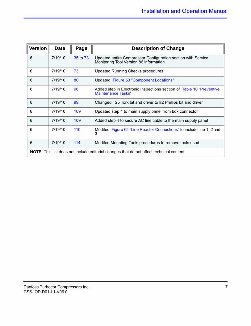
6 7/19/10 35 to 73 Updated entire Compressor Configuration section with Service Monitoring Tool Version 86 information
6 7/19/10 73 Updated Running Checks procedures
6 7/19/10 80 Updated Figure 53 "Component Locations"
6 7/19/10 96 Added step in Electronic Inspections section of Table 10 "Preventive Maintenance Tasks"
6 7/19/10 99 Changed T25 Torx bit and driver to #2 Phillips bit and driver
6 7/19/10 109 Updated step 4 to main supply panel from box connector
6 7/19/10 109 Added step 4 to secure AC line cable to the main supply panel
6 7/19/10 110 Modifed Figure 65 "Line Reactor Connections" to include line 1, 2 and 3
6 7/19/10 114 Modifed Mounting Tools procedures to remove tools used
NOTE: This list does not include editorial changes that do not affect technical content.
Version Date Page Description of Change
Danfoss Turbocor Compressors Inc. 7CSS-IOP-D01-L1-V06.0

This Page Left Intentionally Blank
Installation and Operation Manual
1 Introduction
The purpose of this manual is to inform original equipment manufacturers (OEMs), contractors and their engineers of the recommended methods for proper installation and operation for the Danfoss Turbocor twin-turbine (two-stage) centrifugal compressor.
2 Tools
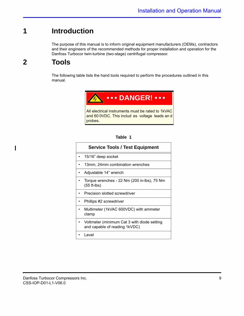
The following table lists the hand tools required to perform the procedures outlined in this manual.
• • • DANGER! • • •All electrical instruments must be rated to 1kVAC and 60 0VDC. This includ es voltage leads an d probes.
Table 1
Service Tools / Test Equipment
• 15/16” deep socket
• 13mm, 24mm combination wrenches
• Adjustable 14” wrench
• Torque wrenches - 22 Nm (200 in-lbs), 75 Nm (55 ft-lbs)
• Precision slotted screwdriver
• Phillips #2 screwdriver
• Multimeter (1kVAC 600VDC) with ammeter clamp
• Voltmeter (minimum Cat 3 with diode setting and capable of reading 1kVDC)
• Level
Danfoss Turbocor Compressors Inc. 9CSS-IOP-D01-L1-V06.0
Safety Summary
3 Safety Summary
3.1 Safety Warnings
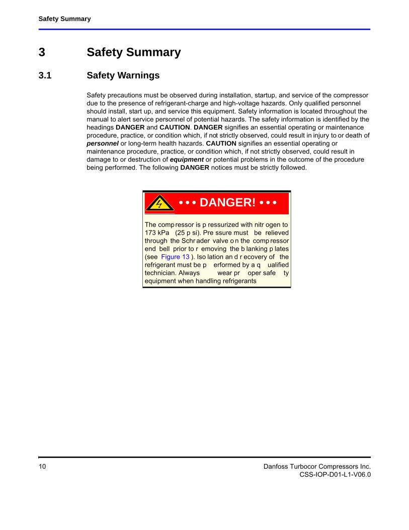
Safety precautions must be observed during installation, startup, and service of the compressor due to the presence of refrigerant-charge and high-voltage hazards. Only qualified personnel should install, start up, and service this equipment. Safety information is located throughout the manual to alert service personnel of potential hazards. The safety information is identified by the headings DANGER and CAUTION. DANGER signifies an essential operating or maintenance procedure, practice, or condition which, if not strictly observed, could result in injury to or death of personnel or long-term health hazards. CAUTION signifies an essential operating or maintenance procedure, practice, or condition which, if not strictly observed, could result in damage to or destruction of equipment or potential problems in the outcome of the procedure being performed. The following DANGER notices must be strictly followed.
The compressor is p ressurized with nitr ogen to 173 kPa (25 p si). Pre ssure must be relieved through the Schr ader valve o n the comp ressor end bell prior to r emoving the b lanking p lates (see Figure 13 ). Iso lation an d r ecovery of the refrigerant must be p erformed by a q ualified technician. Always wear pr oper safe ty equipment when handling refrigerants
• • • DANGER! • • •
10 Danfoss Turbocor Compressors Inc.CSS-IOP-D01-L1-V06.0
Installation and Operation Manual
This e quipment co ntains haza rdous volt ages that can cause injury or death. Only qualified and trained per sonnel sh ould wo rk on hig h-voltage electrical equipment. Removing the mains input cover will expose you to a high-v oltage (380 - 604VAC) haz ard. Removing the top cover will expose you to a hig h-voltage (6 00 - 90 0VDC) hazard. Exercise care wh en w orking a round energized circuits.When se rvicing or re placing a com pressor, the high-voltage cap acitors must be dischar ged before op ening a ny of the com pressor a ccess covers. Perform steps in Section 3.3 on the next page.
• • • DANGER! • • •
Danfoss Turbocor Compressors Inc. 11CSS-IOP-D01-L1-V06.0
Safety Summary
3.2 Voltage Checks Using DC Bus Test Harness (Safety Cable)
Voltage checks with the top covers removed should not be performed. All voltage checks should be performed using the DC Bus Test Harness (PN 100326). Follow the steps below to safely remove power from the compressor and install the DC Bus Test Harness.
Before using the DC Bus Test Harness, integrity of the fuses/resistors and cable must be checked (see Section 3.3).
3.3 Voltage Checks Using DC Bus Test Harness
1. Turn off AC power input to the compressor.
2. Secure/lock out/tag out the isolating switch to ensure against accidental or unauthorized reapplication of the AC power.
3. Wait at least 15 minutes, then remove the mains input cover by releasing the four screws that secure the cover.
4. Using an appropriately rated voltmeter, confirm that the AC voltage is still isolated.
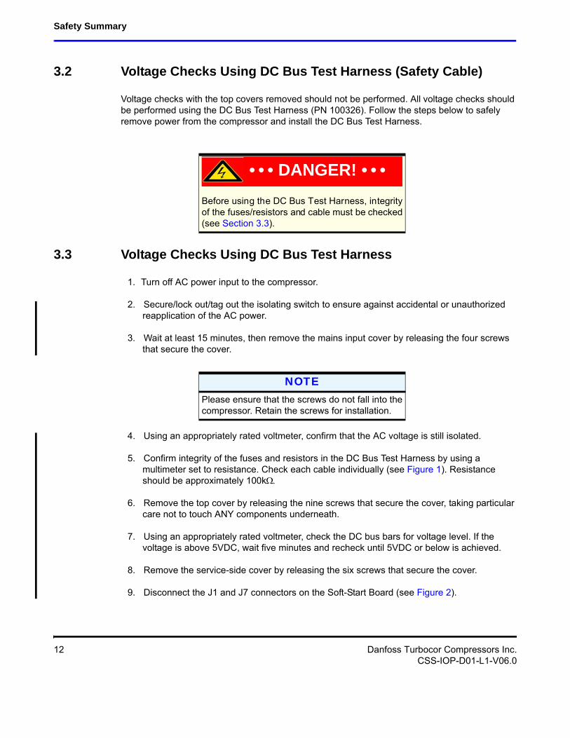
5. Confirm integrity of the fuses and resistors in the DC Bus Test Harness by using a multimeter set to resistance. Check each cable individually (see Figure 1). Resistance should be approximately 100k
6. Remove the top cover by releasing the nine screws that secure the cover, taking particular care not to touch ANY components underneath.
7. Using an appropriately rated voltmeter, check the DC bus bars for voltage level. If the voltage is above 5VDC, wait five minutes and recheck until 5VDC or below is achieved.
8. Remove the service-side cover by releasing the six screws that secure the cover.
9. Disconnect the J1 and J7 connectors on the Soft-Start Board (see Figure 2).
• • • DANGER! • • •
NOTEPlease ensure that the screws do not fall into the compressor. Retain the screws for installation.
12 Danfoss Turbocor Compressors Inc.CSS-IOP-D01-L1-V06.0
Installation and Operation Manual
Figure 1 DC Bus Test Harness
Figure 2 Soft-Start Board
10. Connect the two plugs of the compressor cable harness into corresponding sockets of the DC Bus Test Harness (see Figure 3).
Danfoss Turbocor Compressors Inc. 13CSS-IOP-D01-L1-V06.0
Safety Summary
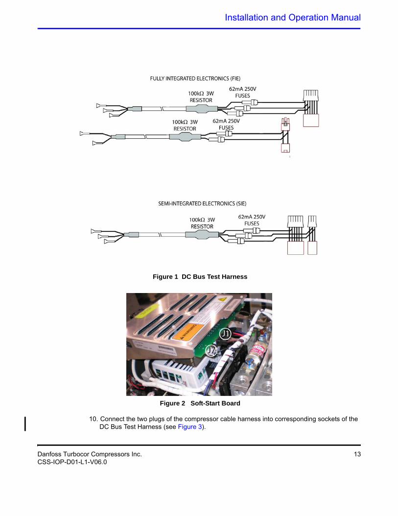
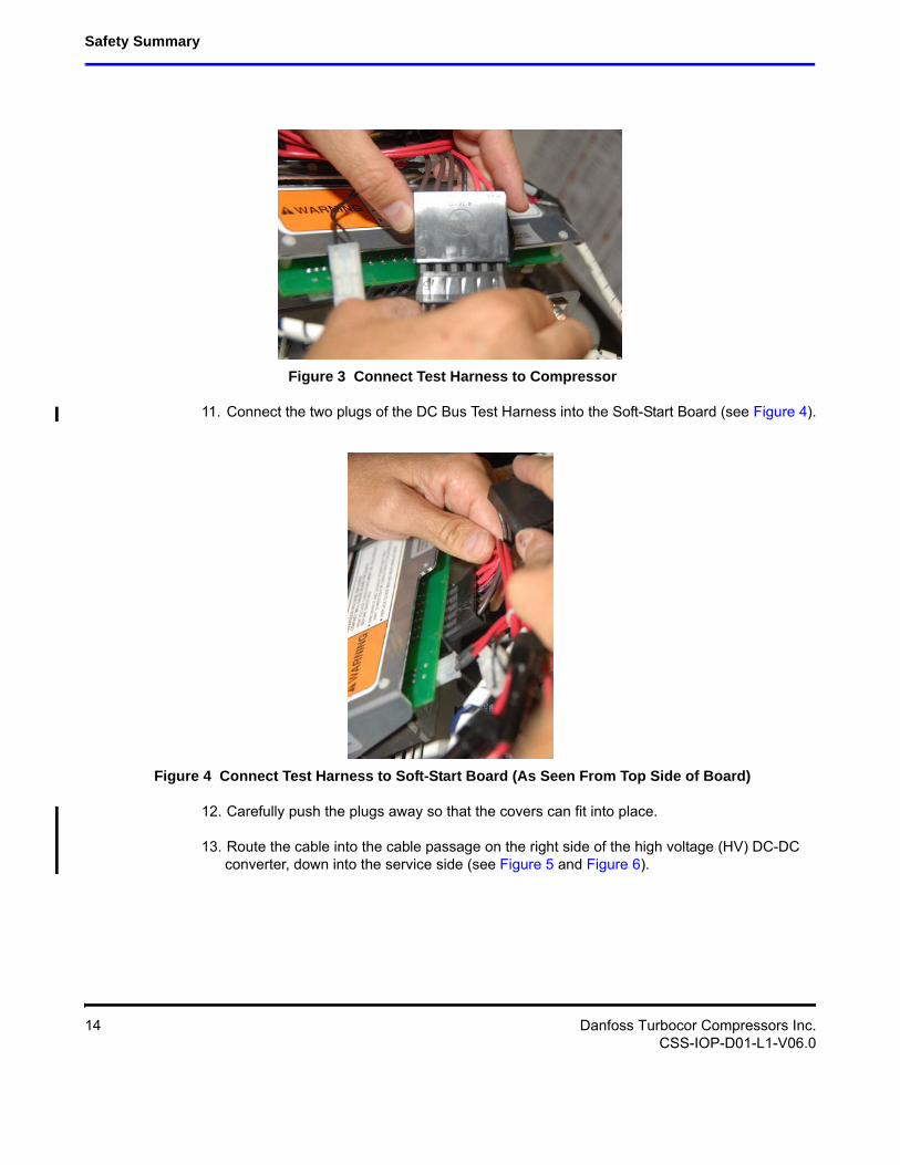
Figure 3 Connect Test Harness to Compressor
11. Connect the two plugs of the DC Bus Test Harness into the Soft-Start Board (see Figure 4).
Figure 4 Connect Test Harness to Soft-Start Board (As Seen From Top Side of Board)
12. Carefully push the plugs away so that the covers can fit into place.
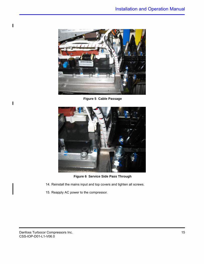
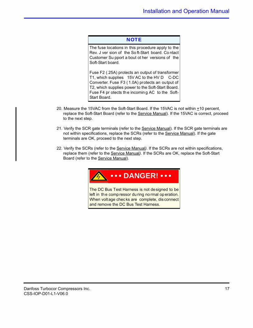
13. Route the cable into the cable passage on the right side of the high voltage (HV) DC-DC converter, down into the service side (see Figure 5 and Figure 6).
14 Danfoss Turbocor Compressors Inc.CSS-IOP-D01-L1-V06.0
Installation and Operation Manual
Figure 5 Cable Passage
Figure 6 Service Side Pass Through
14. Reinstall the mains input and top covers and tighten all screws.
15. Reapply AC power to the compressor.
Danfoss Turbocor Compressors Inc. 15CSS-IOP-D01-L1-V06.0

Safety Summary
16. Using an appropriately rated voltmeter with the 1000VDC range selected, insert the positive voltmeter lead into the DC(+F) test harness lead, and the negative voltmeter lead into the DC(-) test harness lead. See Table 2 for expected DC bus voltage. If the voltage corresponds to Table 2, the DC bus voltage is correct and the HV DC fuse on the Soft-Start Board is good. If the voltage reads zero, go to step 17. If the voltage is within acceptable limits, this indicates that the Soft-Start Board and SCRs are functioning correctly; go to step 20.
17. Leaving the DC(-) test lead in place, relocate the positive (+) test lead to DC(+). If the DC voltage is consistent with Table 2 , the HV DC fuse on the Soft-Start Board is defective. Refer to the Service Manual to verify the HV DC-DC converter.
18. Reset the multimeter scaling to read 15VAC and connect to the 15VAC lead in the DC Bus Test Harness. If the reading is zero, isolate the three-phase supply in accordance with steps 1-7.
19. When access is safe, remove the four screws that hold the Soft-Start Board in position, and check fuses F2 and F3 for continuity (these fuses are located next to the J5 fan connector and between the J1 and J7 connectors on the underside of the Soft-Start Board). Fuse F4 or external in line, as appropriate, should also be checked for continuity.
• If fuses are found to be defective, replace them and return to step 16.
• If voltage is present but outside specifications, go to step 20.
Table 2 Compressor Voltage Ranges
Compressor Nameplate AC Voltage
Acceptable AC Voltage
Range
Expected DC Bus Voltage
575 VAC 518 - 632 VAC 632 - 900 VDC
460 VAC 414 - 506 VAC 550 - 720 VDC
400 VAC 360 - 440 VAC 485 - 625 VDC
380 VAC 342 - 418 VAC 460 - 595 VDC
NOTESee th e Se rvice M anual for pr ocedures o n determining the cause of the blown fuse.
16 Danfoss Turbocor Compressors Inc.CSS-IOP-D01-L1-V06.0
Installation and Operation Manual
20. Measure the 15VAC from the Soft-Start Board. If the 15VAC is not within +10 percent, replace the Soft-Start Board (refer to the Service Manual). If the 15VAC is correct, proceed to the next step.
21. Verify the SCR gate terminals (refer to the Service Manual). If the SCR gate terminals are not within specifications, replace the SCRs (refer to the Service Manual). If the gate terminals are OK, proceed to the next step.
22. Verify the SCRs (refer to the Service Manual). If the SCRs are not within specifications, replace them (refer to the Service Manual). If the SCRs are OK, replace the Soft-Start Board (refer to the Service Manual).
NOTEThe fuse locations in this procedure apply to the Rev. J ver sion of the So ft-Start board. Co ntact Customer Su pport a bout ot her versions of the Soft-Start board.Fuse F2 (.25A) protects an output of transformer T1, which supplies 15V AC to the HV D C-DC Converter. Fuse F3 ( 1.0A) protects an output of T2, which supplies power to the Soft-Start Board. Fuse F4 pr otects th e incomin g AC to the Soft-Start Board.
• • • DANGER! • • •The DC Bus Test Harness is not designed to be left in th e comp ressor du ring no rmal op eration. When voltage chec ks are complete, dis connect and remove the DC Bus Test Harness.
Danfoss Turbocor Compressors Inc. 17CSS-IOP-D01-L1-V06.0
Safety Summary
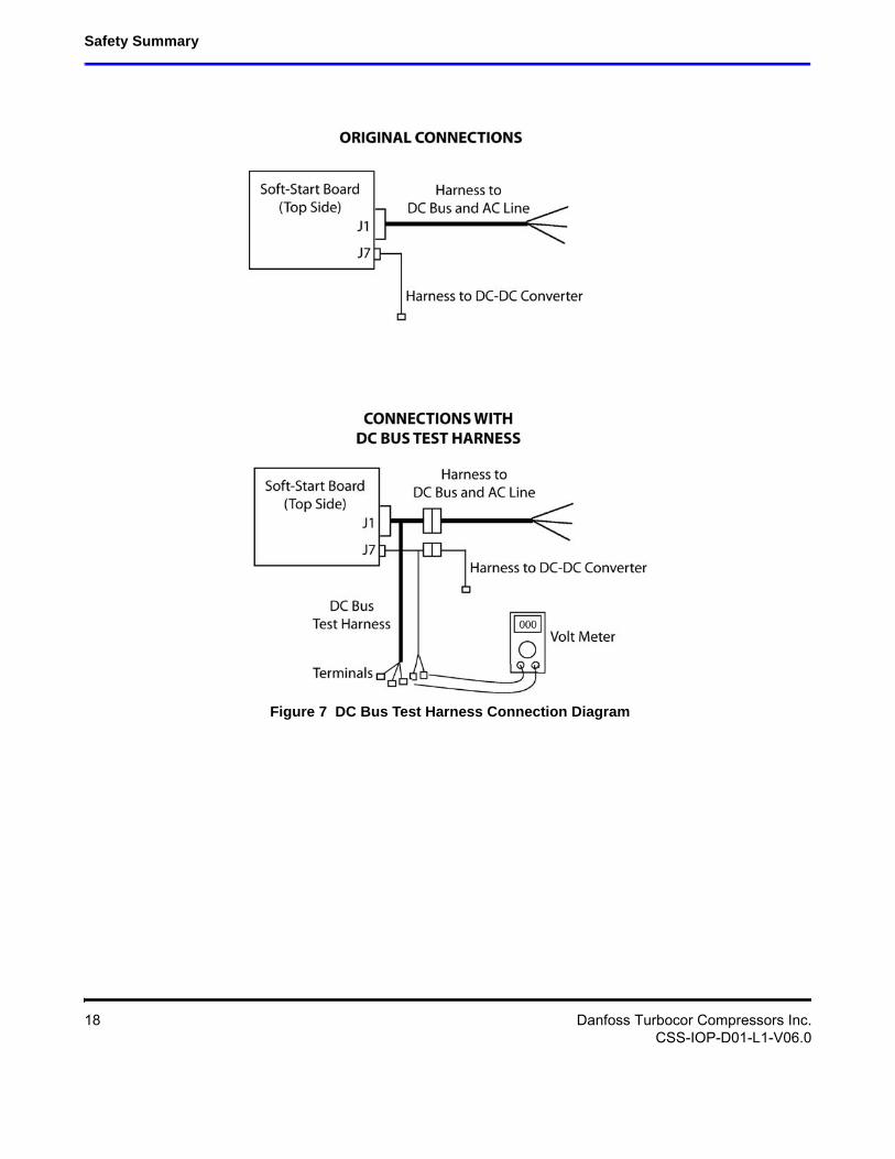
Figure 7 DC Bus Test Harness Connection Diagram
18 Danfoss Turbocor Compressors Inc.CSS-IOP-D01-L1-V06.0
Installation and Operation Manual
4 Installation
4.1 Unpacking and Inspection
The compressor should be carefully inspected for visible signs of damage. Check for loose bolts and damage to covers or outer casing. Damage should first be reported to the carrier not DTC. DTC Customer Support and Service can be contacted to assist in determining the extent of damage or if compressor should be returned to DTC. Damage should be specified on the Bill of Lading or transportation/freight forwarder documentation. Open all containers and verify all parts against the packing list. Report any shortages to DTC. Contact DTC to conduct report actions via the Incident Report form.
4.2 Rigging Requirements
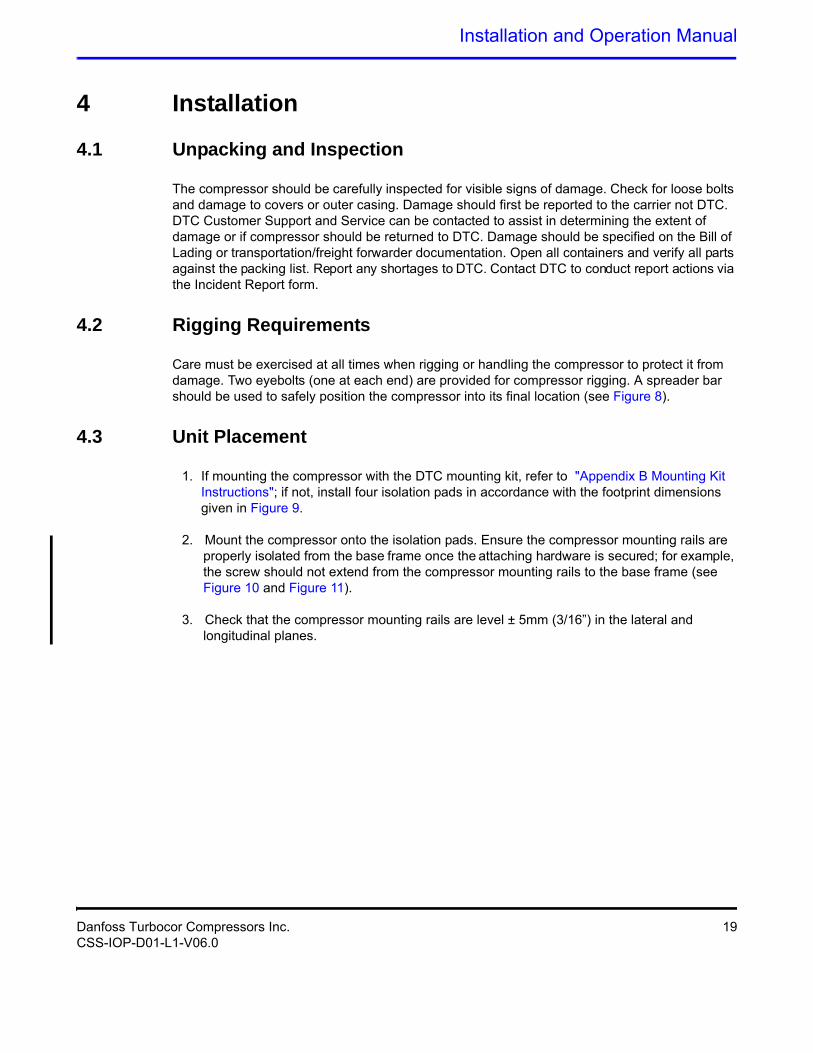
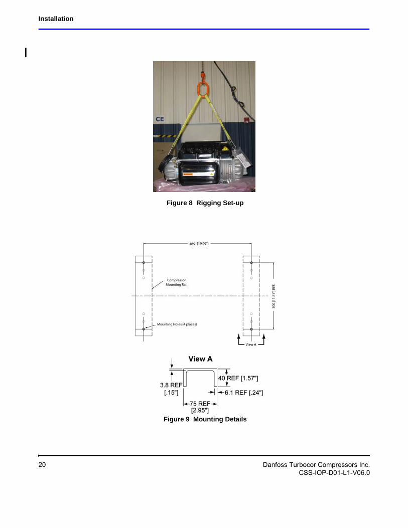
Care must be exercised at all times when rigging or handling the compressor to protect it from damage. Two eyebolts (one at each end) are provided for compressor rigging. A spreader bar should be used to safely position the compressor into its final location (see Figure 8).
4.3 Unit Placement
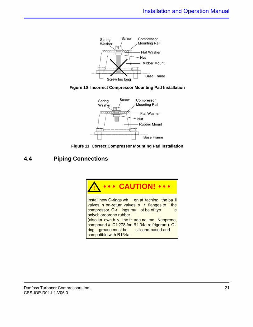
1. If mounting the compressor with the DTC mounting kit, refer to "Appendix B Mounting Kit Instructions"; if not, install four isolation pads in accordance with the footprint dimensions given in Figure 9.
2. Mount the compressor onto the isolation pads. Ensure the compressor mounting rails are properly isolated from the base frame once the attaching hardware is secured; for example, the screw should not extend from the compressor mounting rails to the base frame (see Figure 10 and Figure 11).
3. Check that the compressor mounting rails are level ± 5mm (3/16”) in the lateral and longitudinal planes.
Danfoss Turbocor Compressors Inc. 19CSS-IOP-D01-L1-V06.0
Installation
Figure 8 Rigging Set-up
Figure 9 Mounting Details
20 Danfoss Turbocor Compressors Inc.CSS-IOP-D01-L1-V06.0
Installation and Operation Manual
Figure 10 Incorrect Compressor Mounting Pad Installation
Figure 11 Correct Compressor Mounting Pad Installation
4.4 Piping Connections
! • • • CAUTION! • • •Install new O-rings wh en at taching the ba ll valves, n on-return valves, o r flanges to the compressor. O-r ings mu st be of typ e polychloroprene rubber(also kn own b y the tr ade na me Neoprene, compound # C1 278 for R1 34a re frigerant). O-ring grease must be silicone-based and compatible with R134a.
Danfoss Turbocor Compressors Inc. 21CSS-IOP-D01-L1-V06.0
Installation
1. After releasing the pressure, remove the suction and discharge connection blanking plates from the new compressor.
2. Ensure flange surfaces are clean and free from debris. Install new O-rings.
3. Attach the suction, discharge, and economizer (if applicable) connections. Install O-rings.
4. Solder all joints according to approved practice ensuring that dry nitrogen is used at all times.
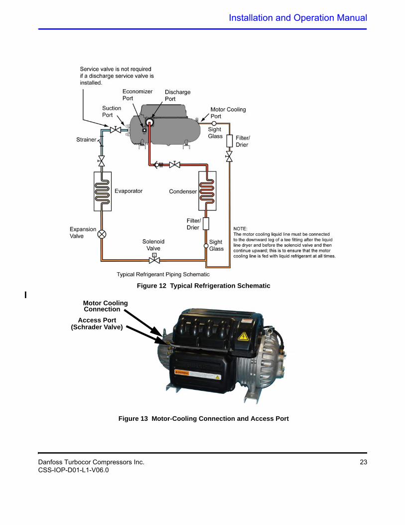
5. Attach the motor-cooling connection at the rear of the compressor (see Figure 13).
6. Install a strainer in the suction line. It should be located between the compressor and the service valve as close as possible to the suction port of the compressor.
7. Perform a leak test, evacuation and charge according to industry standards.
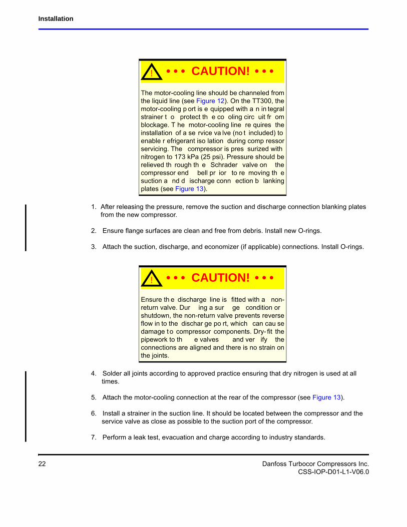
! • • • CAUTION! • • •The motor-cooling line should be channeled from the liquid line (see Figure 12). On the TT300, the motor-cooling p ort is e quipped with a n in tegral strainer t o protect th e co oling circ uit fr om blockage. T he motor-cooling line re quires the installation of a se rvice va lve (no t included) to enable r efrigerant iso lation during comp ressor servicing. The compressor is pres surized with nitrogen to 173 kPa (25 psi). Pressure should be relieved th rough th e Schrader valve on the compressor end bell pr ior to re moving th e suction a nd d ischarge conn ection b lanking plates (see Figure 13).
! • • • CAUTION! • • •Ensure th e discharge line is fitted with a non-return valve. Dur ing a sur ge condition or shutdown, the non-return valve prevents reverse flow in to the dischar ge po rt, which can cau se damage t o compressor components. Dry- fit the pipework to th e valves and ver ify the connections are aligned and there is no strain on the joints.
22 Danfoss Turbocor Compressors Inc.CSS-IOP-D01-L1-V06.0
Installation and Operation Manual
Figure 12 Typical Refrigeration Schematic
Figure 13 Motor-Cooling Connection and Access Port
Motor CoolingConnection
Access Port(Schrader Valve)
Danfoss Turbocor Compressors Inc. 23CSS-IOP-D01-L1-V06.0
Installation
4.5 Control Wiring
The compressor I/O Board enables communication of control and status signals between the compressor controller and external equipment. These signals include, among others, cooling demand, input, EXV control inputs and outputs, alarm and interlock contacts, and Modbus protocol communications.
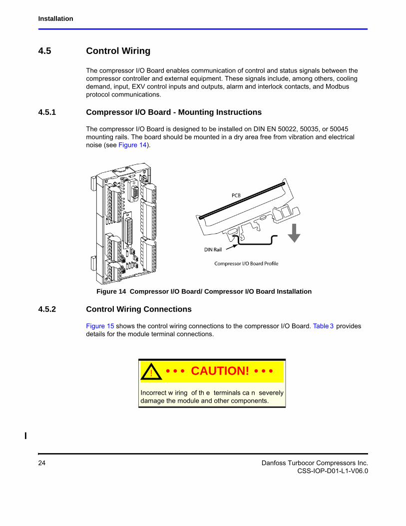
4.5.1 Compressor I/O Board - Mounting Instructions
The compressor I/O Board is designed to be installed on DIN EN 50022, 50035, or 50045 mounting rails. The board should be mounted in a dry area free from vibration and electrical noise (see Figure 14).
Figure 14 Compressor I/O Board/ Compressor I/O Board Installation
4.5.2 Control Wiring Connections
Figure 15 shows the control wiring connections to the compressor I/O Board. Table 3 provides details for the module terminal connections.
! • • • CAUTION! • • •Incorrect w iring of th e terminals ca n severely damage the module and other components.
24 Danfoss Turbocor Compressors Inc.CSS-IOP-D01-L1-V06.0
Installation and Operation Manual
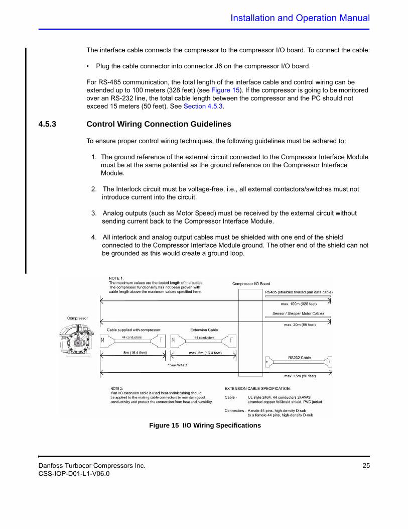
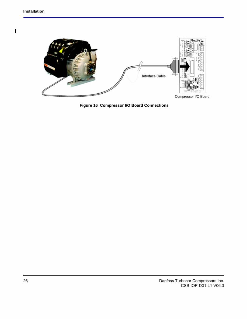
The interface cable connects the compressor to the compressor I/O board. To connect the cable:
• Plug the cable connector into connector J6 on the compressor I/O board.
For RS-485 communication, the total length of the interface cable and control wiring can be extended up to 100 meters (328 feet) (see Figure 15). If the compressor is going to be monitored over an RS-232 line, the total cable length between the compressor and the PC should not exceed 15 meters (50 feet). See Section 4.5.3.
4.5.3 Control Wiring Connection Guidelines
To ensure proper control wiring techniques, the following guidelines must be adhered to:
1. The ground reference of the external circuit connected to the Compressor Interface Module must be at the same potential as the ground reference on the Compressor Interface Module.
2. The Interlock circuit must be voltage-free, i.e., all external contactors/switches must not introduce current into the circuit.
3. Analog outputs (such as Motor Speed) must be received by the external circuit without sending current back to the Compressor Interface Module.
4. All interlock and analog output cables must be shielded with one end of the shield connected to the Compressor Interface Module ground. The other end of the shield can not be grounded as this would create a ground loop.
Figure 15 I/O Wiring Specifications
Danfoss Turbocor Compressors Inc. 25CSS-IOP-D01-L1-V06.0
Installation
Figure 16 Compressor I/O Board Connections
26 Danfoss Turbocor Compressors Inc.CSS-IOP-D01-L1-V06.0
Installation and Operation Manual
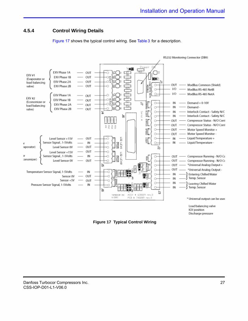
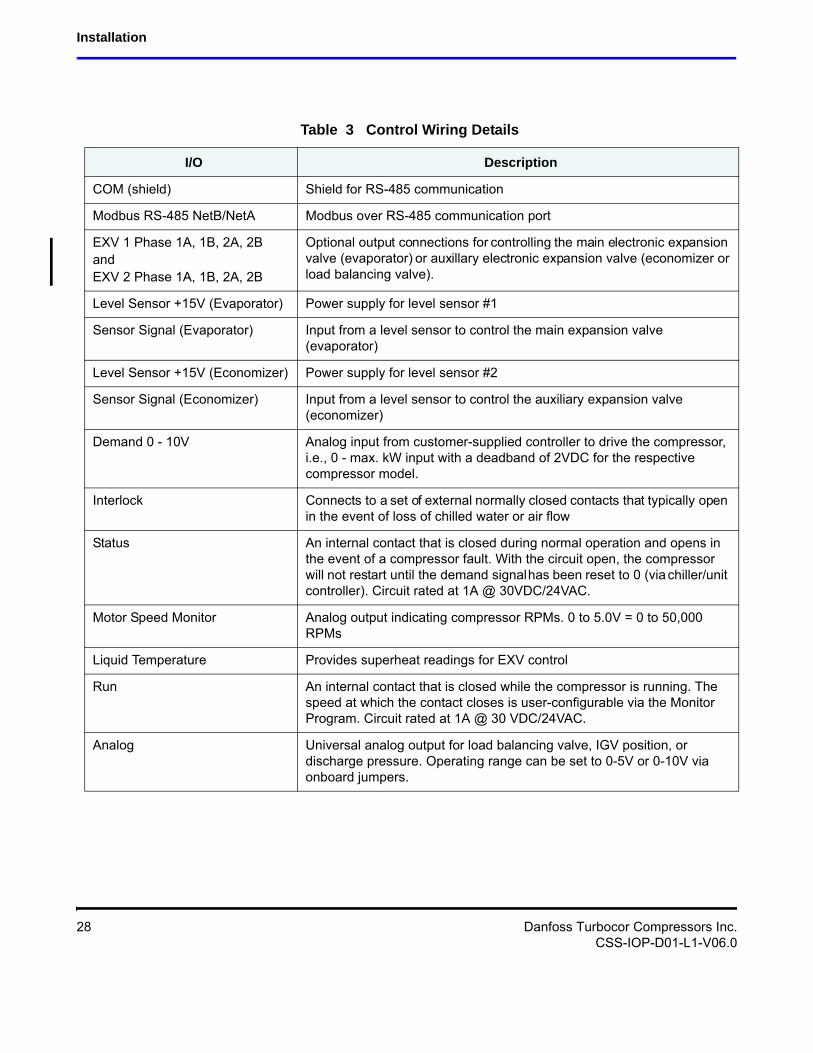
4.5.4 Control Wiring Details
Figure 17 shows the typical control wiring. See Table 3 for a description.
Figure 17 Typical Control Wiring
Danfoss Turbocor Compressors Inc. 27CSS-IOP-D01-L1-V06.0
Installation
Table 3 Control Wiring Details
I/O Description
COM (shield) Shield for RS-485 communication
Modbus RS-485 NetB/NetA Modbus over RS-485 communication port
EXV 1 Phase 1A, 1B, 2A, 2BandEXV 2 Phase 1A, 1B, 2A, 2B
Optional output connections for controlling the main electronic expansion valve (evaporator) or auxillary electronic expansion valve (economizer or load balancing valve).
Level Sensor +15V (Evaporator) Power supply for level sensor #1
Sensor Signal (Evaporator) Input from a level sensor to control the main expansion valve (evaporator)
Level Sensor +15V (Economizer) Power supply for level sensor #2
Sensor Signal (Economizer) Input from a level sensor to control the auxiliary expansion valve (economizer)
Demand 0 - 10V Analog input from customer-supplied controller to drive the compressor, i.e., 0 - max. kW input with a deadband of 2VDC for the respective compressor model.
Interlock Connects to a set of external normally closed contacts that typically open in the event of loss of chilled water or air flow
Status An internal contact that is closed during normal operation and opens in the event of a compressor fault. With the circuit open, the compressor will not restart until the demand signal has been reset to 0 (via chiller/unit controller). Circuit rated at 1A @ 30VDC/24VAC.
Motor Speed Monitor Analog output indicating compressor RPMs. 0 to 5.0V = 0 to 50,000 RPMs
Liquid Temperature Provides superheat readings for EXV control
Run An internal contact that is closed while the compressor is running. The speed at which the contact closes is user-configurable via the Monitor Program. Circuit rated at 1A @ 30 VDC/24VAC.
Analog Universal analog output for load balancing valve, IGV position, or discharge pressure. Operating range can be set to 0-5V or 0-10V via onboard jumpers.
28 Danfoss Turbocor Compressors Inc.CSS-IOP-D01-L1-V06.0
Installation and Operation Manual
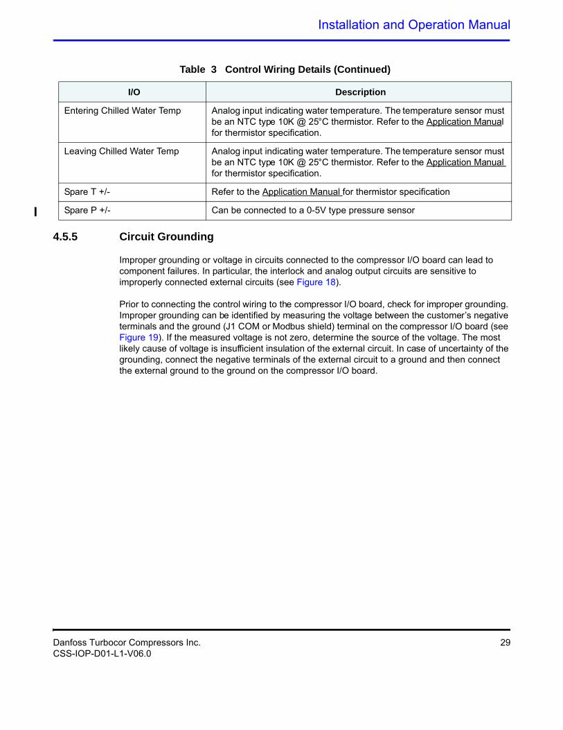
4.5.5 Circuit Grounding
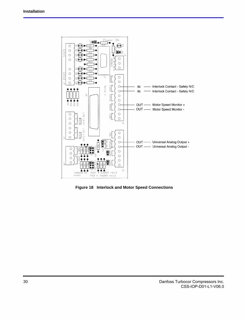
Improper grounding or voltage in circuits connected to the compressor I/O board can lead to component failures. In particular, the interlock and analog output circuits are sensitive to improperly connected external circuits (see Figure 18).
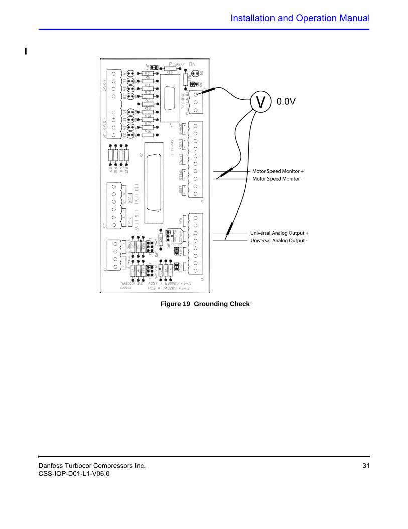
Prior to connecting the control wiring to the compressor I/O board, check for improper grounding. Improper grounding can be identified by measuring the voltage between the customer’s negative terminals and the ground (J1 COM or Modbus shield) terminal on the compressor I/O board (see Figure 19). If the measured voltage is not zero, determine the source of the voltage. The most likely cause of voltage is insufficient insulation of the external circuit. In case of uncertainty of the grounding, connect the negative terminals of the external circuit to a ground and then connect the external ground to the ground on the compressor I/O board.
Entering Chilled Water Temp Analog input indicating water temperature. The temperature sensor must be an NTC type 10K @ 25°C thermistor. Refer to the Application Manual for thermistor specification.
Leaving Chilled Water Temp Analog input indicating water temperature. The temperature sensor must be an NTC type 10K @ 25°C thermistor. Refer to the Application Manual for thermistor specification.
Spare T +/- Refer to the Application Manual for thermistor specification
Spare P +/- Can be connected to a 0-5V type pressure sensor
Table 3 Control Wiring Details (Continued)
I/O Description
Danfoss Turbocor Compressors Inc. 29CSS-IOP-D01-L1-V06.0
Installation
Figure 18 Interlock and Motor Speed Connections
30 Danfoss Turbocor Compressors Inc.CSS-IOP-D01-L1-V06.0
Installation and Operation Manual
Figure 19 Grounding Check
Danfoss Turbocor Compressors Inc. 31CSS-IOP-D01-L1-V06.0
Installation
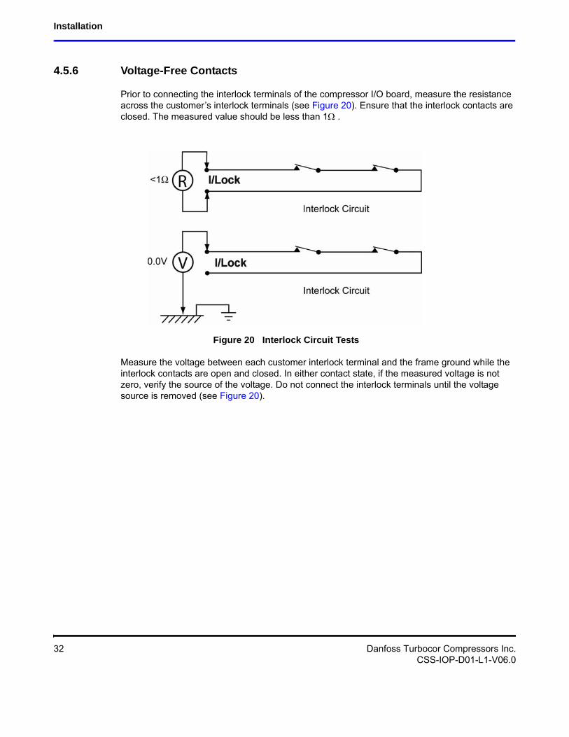
4.5.6 Voltage-Free Contacts
Prior to connecting the interlock terminals of the compressor I/O board, measure the resistance across the customer’s interlock terminals (see Figure 20). Ensure that the interlock contacts are closed. The measured value should be less than 1 .
Figure 20 Interlock Circuit Tests
Measure the voltage between each customer interlock terminal and the frame ground while the interlock contacts are open and closed. In either contact state, if the measured voltage is not zero, verify the source of the voltage. Do not connect the interlock terminals until the voltage source is removed (see Figure 20).
32 Danfoss Turbocor Compressors Inc.CSS-IOP-D01-L1-V06.0
Installation and Operation Manual
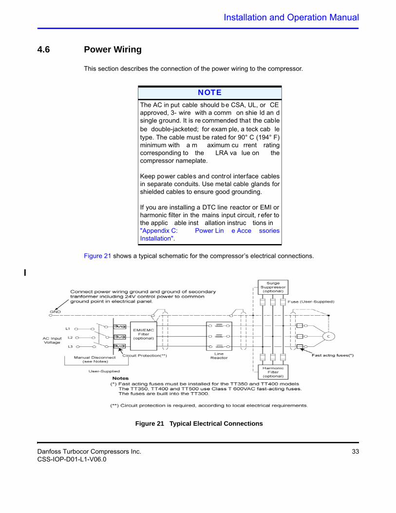
4.6 Power Wiring
This section describes the connection of the power wiring to the compressor.
Figure 21 shows a typical schematic for the compressor’s electrical connections.
Figure 21 Typical Electrical Connections
NOTEThe AC in put cable should be CSA, UL, or CE approved, 3- wire with a comm on shie ld an d single ground. It is re commended that the cable be double-jacketed; for exam ple, a teck cab le type. The cable must be rated for 90° C (194° F) minimum with a m aximum cu rrent rating corresponding to the LRA va lue on the compressor nameplate. Keep power cables and control interface cables in separate conduits. Use metal cable glands for shielded cables to ensure good grounding.If you are installing a DTC line reactor or EMI or harmonic filter in the mains input circuit, r efer to the applic able inst allation instruc tions in "Appendix C: Power Lin e Acce ssories Installation".
Danfoss Turbocor Compressors Inc. 33CSS-IOP-D01-L1-V06.0
Installation
1. Release the four screws that secure the mains input cover to the compressor. Lift away cover.
2. Insert a cable gland (customer-supplied) into the opening in the mains input bracket.
3. Fasten the cable gland to the bracket with the locknut.
4. Feed the AC input cable through the cable gland.
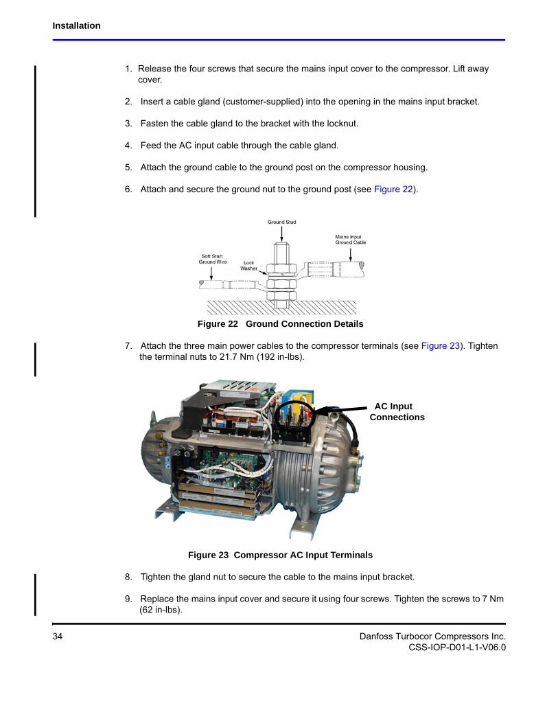
5. Attach the ground cable to the ground post on the compressor housing.
6. Attach and secure the ground nut to the ground post (see Figure 22).
Figure 22 Ground Connection Details
7. Attach the three main power cables to the compressor terminals (see Figure 23). Tighten the terminal nuts to 21.7 Nm (192 in-lbs).
Figure 23 Compressor AC Input Terminals
8. Tighten the gland nut to secure the cable to the mains input bracket.
9. Replace the mains input cover and secure it using four screws. Tighten the screws to 7 Nm (62 in-lbs).
AC InputConnections
34 Danfoss Turbocor Compressors Inc.CSS-IOP-D01-L1-V06.0
Installation and Operation Manual
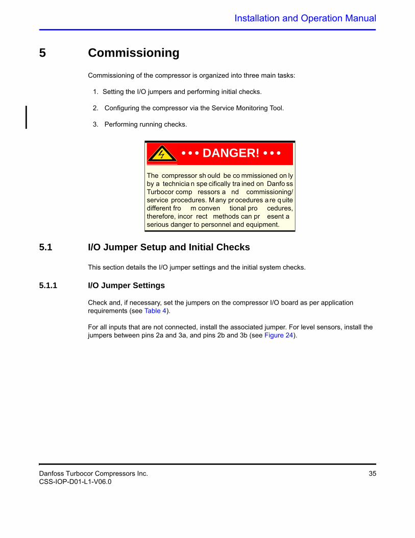
5 Commissioning
Commissioning of the compressor is organized into three main tasks:
1. Setting the I/O jumpers and performing initial checks.
2. Configuring the compressor via the Service Monitoring Tool.
3. Performing running checks.
5.1 I/O Jumper Setup and Initial Checks
This section details the I/O jumper settings and the initial system checks.
5.1.1 I/O Jumper Settings
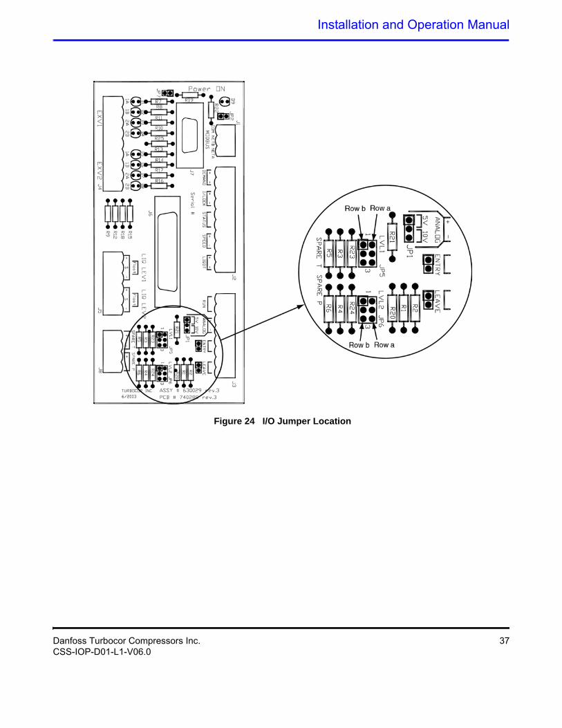
Check and, if necessary, set the jumpers on the compressor I/O board as per application requirements (see Table 4).
For all inputs that are not connected, install the associated jumper. For level sensors, install the jumpers between pins 2a and 3a, and pins 2b and 3b (see Figure 24).
• • • DANGER! • • •The compressor sh ould be co mmissioned on ly by a technicia n spe cifically tra ined on Danfo ss Turbocor comp ressors a nd commissioning/service procedures. Many procedures a re quite different fro m conven tional pro cedures, therefore, incor rect methods can pr esent a serious danger to personnel and equipment.
Danfoss Turbocor Compressors Inc. 35CSS-IOP-D01-L1-V06.0
Commissioning
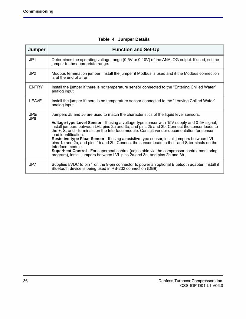
Table 4 Jumper Details
Jumper Function and Set-Up
JP1 Determines the operating voltage range (0-5V or 0-10V) of the ANALOG output. If used, set the jumper to the appropriate range.
JP2 Modbus termination jumper: install the jumper if Modbus is used and if the Modbus connection is at the end of a run
ENTRY Install the jumper if there is no temperature sensor connected to the “Entering Chilled Water” analog input
LEAVE Install the jumper if there is no temperature sensor connected to the “Leaving Chilled Water” analog input
JP5/ JP6
Jumpers J5 and J6 are used to match the characteristics of the liquid level sensors.
Voltage-type Level Sensor - If using a voltage-type sensor with 15V supply and 0-5V signal, install jumpers between LVL pins 2a and 3a, and pins 2b and 3b. Connect the sensor leads to the +, S, and - terminals on the Interface module. Consult vendor documentation for sensor lead identification.Resistive-type Float Sensor - If using a resistive-type sensor, install jumpers between LVL pins 1a and 2a, and pins 1b and 2b. Connect the sensor leads to the - and S terminals on the Interface module.Superheat Control - For superheat control (adjustable via the compressor control monitoring program), install jumpers between LVL pins 2a and 3a, and pins 2b and 3b.
JP7 Supplies 5VDC to pin 1 on the 9-pin connector to power an optional Bluetooth adapter. Install if Bluetooth device is being used in RS-232 connection (DB9).
36 Danfoss Turbocor Compressors Inc.CSS-IOP-D01-L1-V06.0
Installation and Operation Manual
Figure 24 I/O Jumper Location
Danfoss Turbocor Compressors Inc. 37CSS-IOP-D01-L1-V06.0
Commissioning
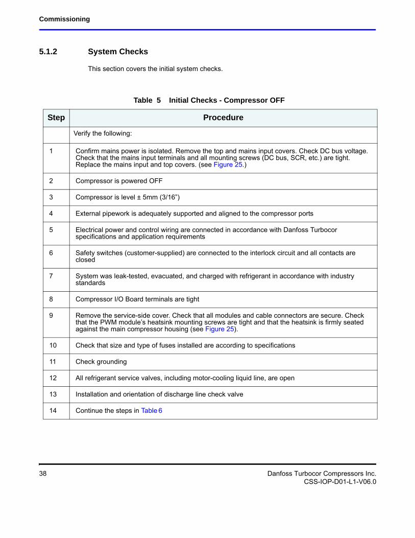
5.1.2 System Checks
This section covers the initial system checks.
Table 5 Initial Checks - Compressor OFF
Step Procedure
Verify the following:
1 Confirm mains power is isolated. Remove the top and mains input covers. Check DC bus voltage. Check that the mains input terminals and all mounting screws (DC bus, SCR, etc.) are tight. Replace the mains input and top covers. (see Figure 25.)
2 Compressor is powered OFF
3 Compressor is level ± 5mm (3/16”)
4 External pipework is adequately supported and aligned to the compressor ports
5 Electrical power and control wiring are connected in accordance with Danfoss Turbocor specifications and application requirements
6 Safety switches (customer-supplied) are connected to the interlock circuit and all contacts are closed
7 System was leak-tested, evacuated, and charged with refrigerant in accordance with industry standards
8 Compressor I/O Board terminals are tight
9 Remove the service-side cover. Check that all modules and cable connectors are secure. Check that the PWM module’s heatsink mounting screws are tight and that the heatsink is firmly seated against the main compressor housing (see Figure 25).
10 Check that size and type of fuses installed are according to specifications
11 Check grounding
12 All refrigerant service valves, including motor-cooling liquid line, are open
13 Installation and orientation of discharge line check valve
14 Continue the steps in Table 6
38 Danfoss Turbocor Compressors Inc.CSS-IOP-D01-L1-V06.0
Installation and Operation Manual
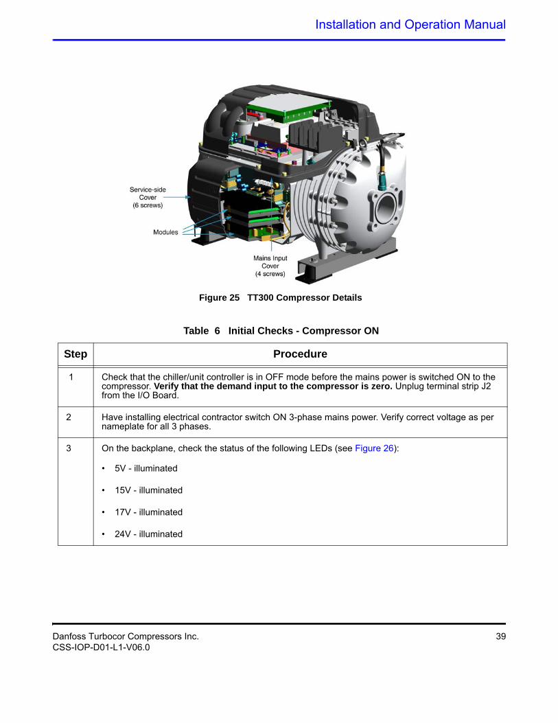
Figure 25 TT300 Compressor Details
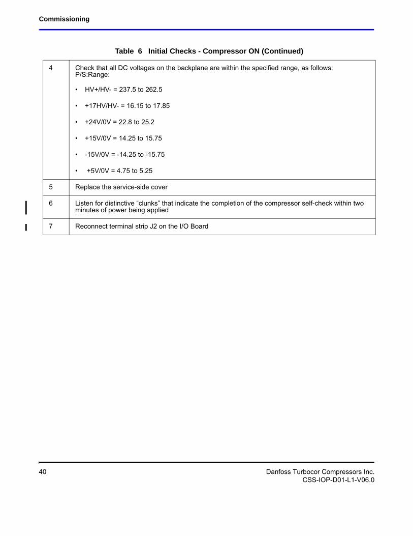
Table 6 Initial Checks - Compressor ON
Step Procedure
1 Check that the chiller/unit controller is in OFF mode before the mains power is switched ON to the compressor. Verify that the demand input to the compressor is zero. Unplug terminal strip J2 from the I/O Board.
2 Have installing electrical contractor switch ON 3-phase mains power. Verify correct voltage as per nameplate for all 3 phases.
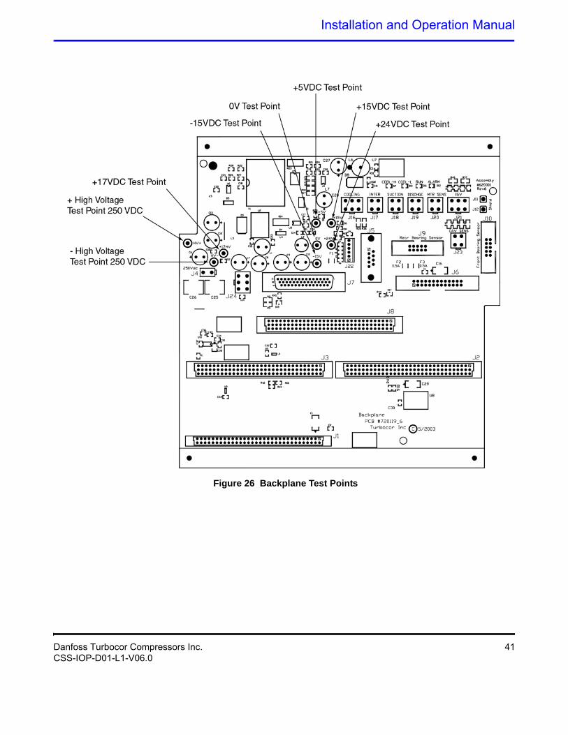
3 On the backplane, check the status of the following LEDs (see Figure 26):
• 5V - illuminated
• 15V - illuminated
• 17V - illuminated
• 24V - illuminated
Danfoss Turbocor Compressors Inc. 39CSS-IOP-D01-L1-V06.0
Commissioning
4 Check that all DC voltages on the backplane are within the specified range, as follows:P/S:Range:
• HV+/HV- = 237.5 to 262.5
• +17HV/HV- = 16.15 to 17.85
• +24V/0V = 22.8 to 25.2
• +15V/0V = 14.25 to 15.75
• -15V/0V = -14.25 to -15.75
• +5V/0V = 4.75 to 5.25
5 Replace the service-side cover
6 Listen for distinctive “clunks” that indicate the completion of the compressor self-check within two minutes of power being applied
7 Reconnect terminal strip J2 on the I/O Board
Table 6 Initial Checks - Compressor ON (Continued)
40 Danfoss Turbocor Compressors Inc.CSS-IOP-D01-L1-V06.0
Installation and Operation Manual
Figure 26 Backplane Test Points
Danfoss Turbocor Compressors Inc. 41CSS-IOP-D01-L1-V06.0
Commissioning
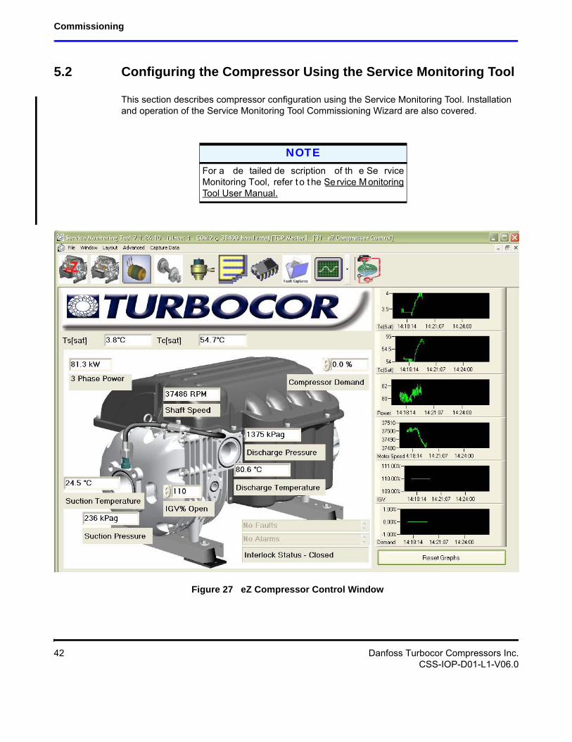
5.2 Configuring the Compressor Using the Service Monitoring Tool
This section describes compressor configuration using the Service Monitoring Tool. Installation and operation of the Service Monitoring Tool Commissioning Wizard are also covered.
Figure 27 eZ Compressor Control Window
NOTEFor a de tailed de scription of th e Se rvice Monitoring Tool, refer t o t he Se rvice M onitoring Tool User Manual.
42 Danfoss Turbocor Compressors Inc.CSS-IOP-D01-L1-V06.0
Installation and Operation Manual
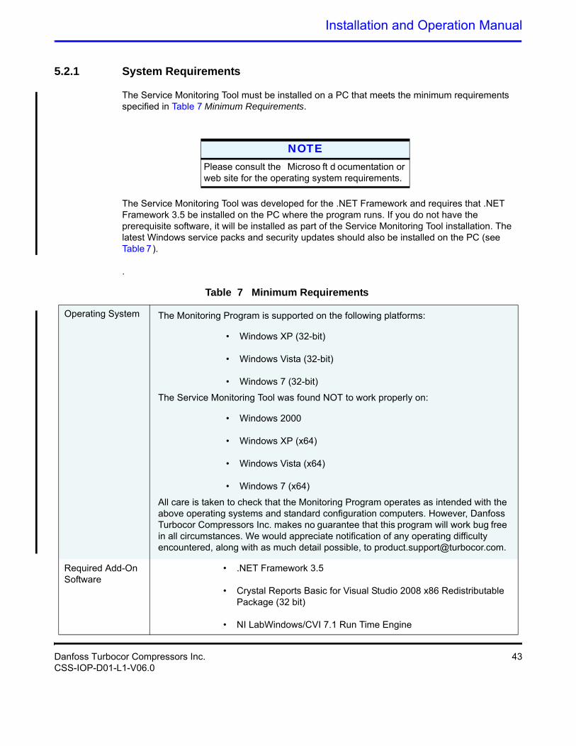
5.2.1 System Requirements
The Service Monitoring Tool must be installed on a PC that meets the minimum requirements specified in Table 7 Minimum Requirements.
The Service Monitoring Tool was developed for the .NET Framework and requires that .NET Framework 3.5 be installed on the PC where the program runs. If you do not have the prerequisite software, it will be installed as part of the Service Monitoring Tool installation. The latest Windows service packs and security updates should also be installed on the PC (see Table 7).
.
NOTEPlease consult the Microso ft d ocumentation or web site for the operating system requirements.
Table 7 Minimum Requirements
Operating System The Monitoring Program is supported on the following platforms:
• Windows XP (32-bit)
• Windows Vista (32-bit)
• Windows 7 (32-bit)
The Service Monitoring Tool was found NOT to work properly on:
• Windows 2000
• Windows XP (x64)
• Windows Vista (x64)
• Windows 7 (x64)
All care is taken to check that the Monitoring Program operates as intended with the above operating systems and standard configuration computers. However, Danfoss Turbocor Compressors Inc. makes no guarantee that this program will work bug free in all circumstances. We would appreciate notification of any operating difficulty encountered, along with as much detail possible, to [email protected].
Required Add-On Software
• .NET Framework 3.5
• Crystal Reports Basic for Visual Studio 2008 x86 Redistributable Package (32 bit)
• NI LabWindows/CVI 7.1 Run Time Engine
Danfoss Turbocor Compressors Inc. 43CSS-IOP-D01-L1-V06.0
Commissioning
5.2.2 Software Installation
The Service Monitoring Tool is installed on the PC and communicates with the compressor using the Modbus protocol over a RS-232 or RS-485 serial link. Administrator privileges may be required to install and remove software on the PC. Security software may block the installation, as well.
If a previous version of the Service Monitoring Tool is already installed on the PC, it must be uninstalled before proceeding with the current installation. To uninstall the Service Monitoring Tool: from the Start menu, select Settings Control Panel. Double-click Add/Remove Programs. From the list, select Danfoss Turbocor Service Monitoring Tool and then click the Remove button.
5.2.3 Monitoring Tool Installation
To download and install the Monitoring Tool, complete the following steps:
1. From Internet Explorer, go to www.turbocor.com.
2. Click on Product Support.
3. Log-in using your user name and password.
4. Click on Monitoring Program.
5. Select Full-Integrated Electronics.
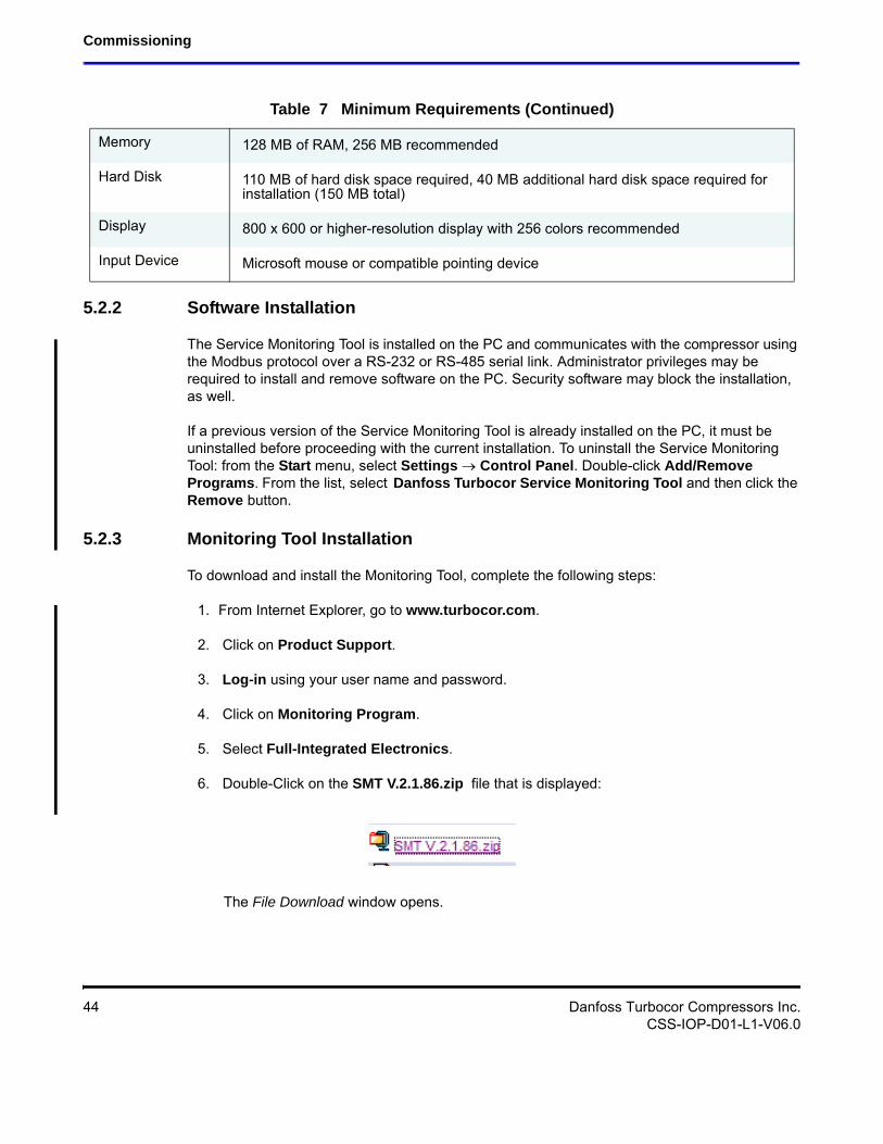
6. Double-Click on the SMT V.2.1.86.zip file that is displayed:
The File Download window opens.
Memory 128 MB of RAM, 256 MB recommended
Hard Disk 110 MB of hard disk space required, 40 MB additional hard disk space required for installation (150 MB total)
Display 800 x 600 or higher-resolution display with 256 colors recommended
Input Device Microsoft mouse or compatible pointing device
Table 7 Minimum Requirements (Continued)
44 Danfoss Turbocor Compressors Inc.CSS-IOP-D01-L1-V06.0
Installation and Operation Manual
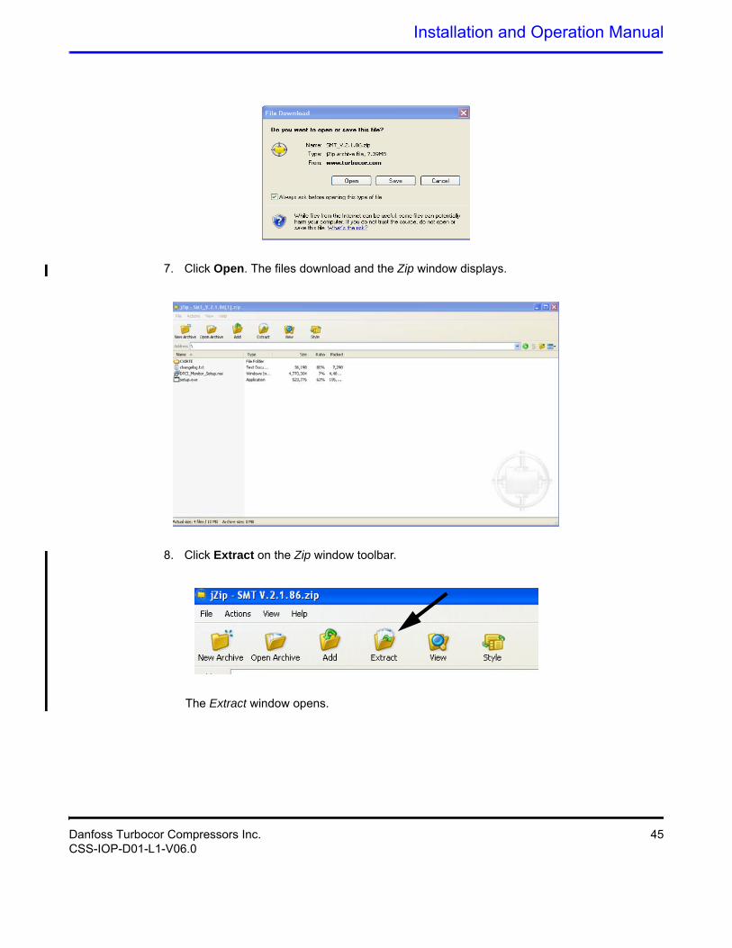
7. Click Open. The files download and the Zip window displays.
8. Click Extract on the Zip window toolbar.
The Extract window opens.
Danfoss Turbocor Compressors Inc. 45CSS-IOP-D01-L1-V06.0
Commissioning
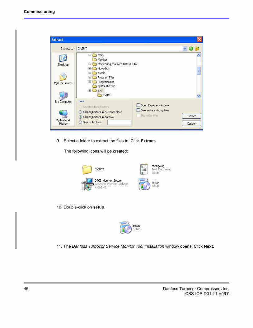
9. Select a folder to extract the files to. Click Extract.
The following icons will be created:
10. Double-click on setup.
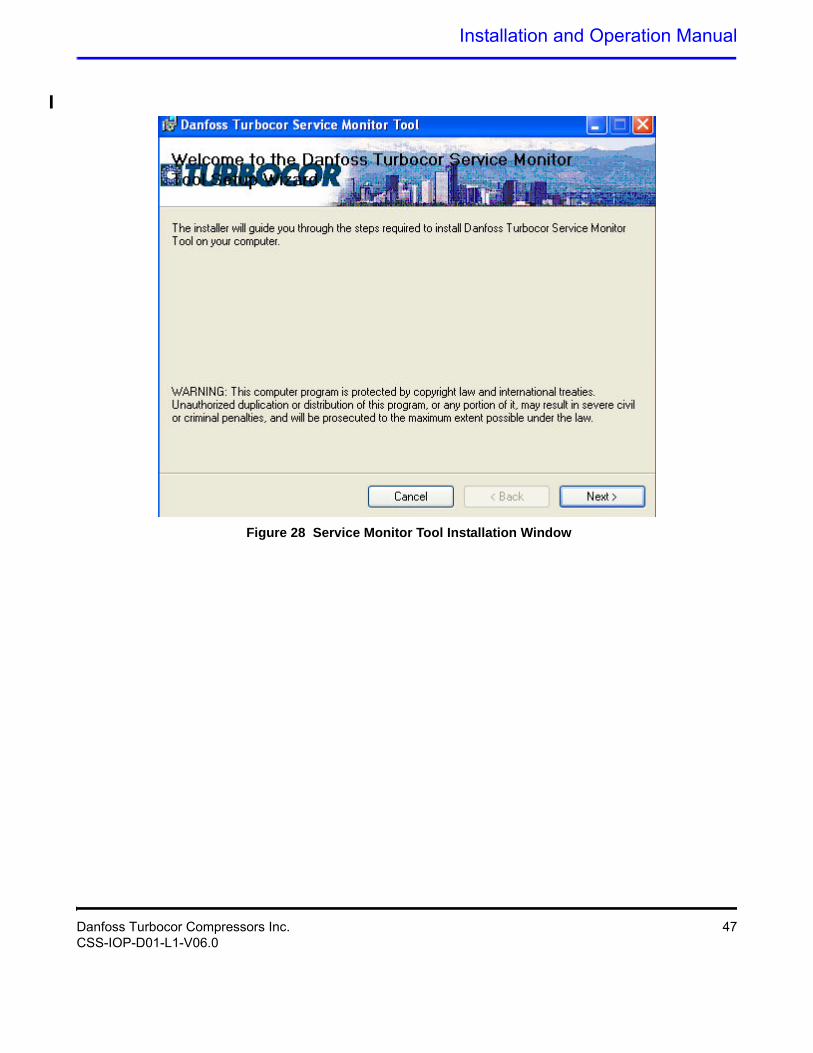
11. The Danfoss Turbocor Service Monitor Tool Installation window opens. Click Next.
46 Danfoss Turbocor Compressors Inc.CSS-IOP-D01-L1-V06.0
Installation and Operation Manual
Figure 28 Service Monitor Tool Installation Window
Danfoss Turbocor Compressors Inc. 47CSS-IOP-D01-L1-V06.0
Commissioning
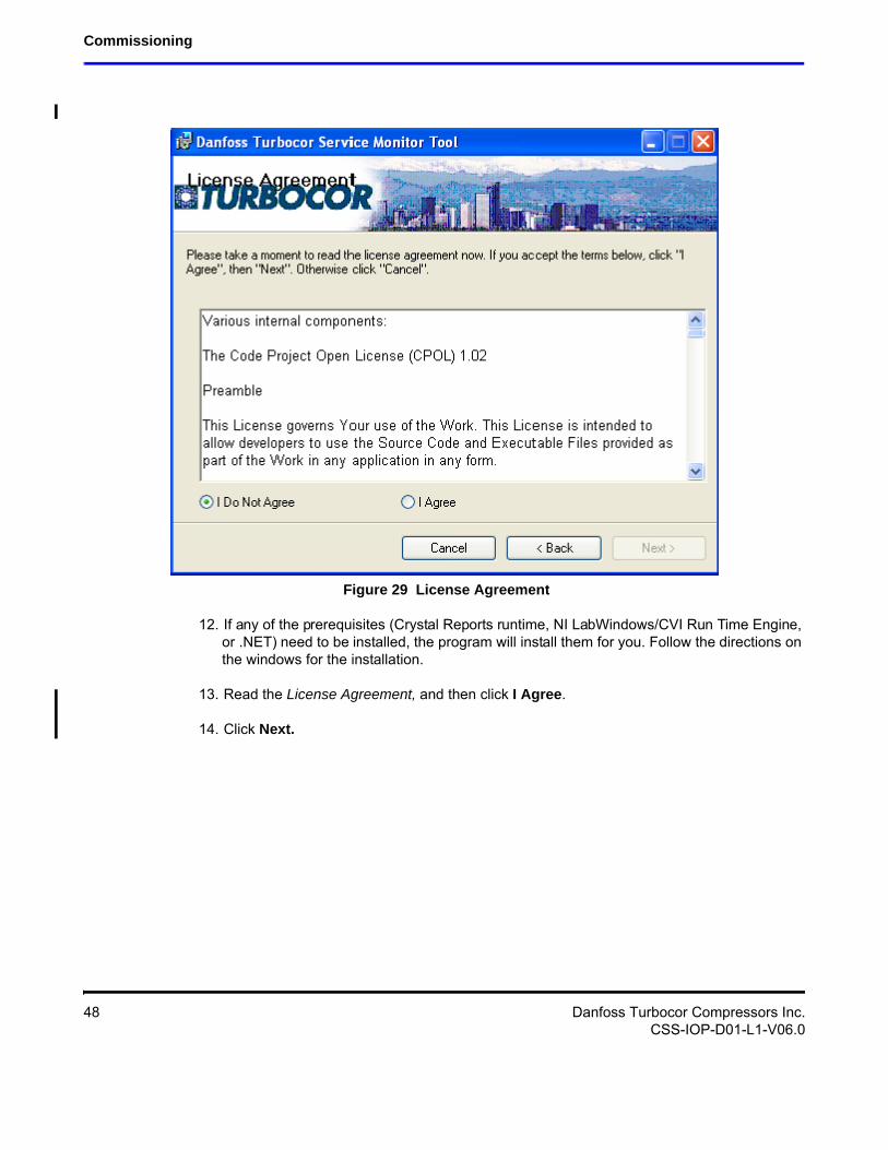
Figure 29 License Agreement
12. If any of the prerequisites (Crystal Reports runtime, NI LabWindows/CVI Run Time Engine, or .NET) need to be installed, the program will install them for you. Follow the directions on the windows for the installation.
13. Read the License Agreement, and then click I Agree.
14. Click Next.
48 Danfoss Turbocor Compressors Inc.CSS-IOP-D01-L1-V06.0
Installation and Operation Manual
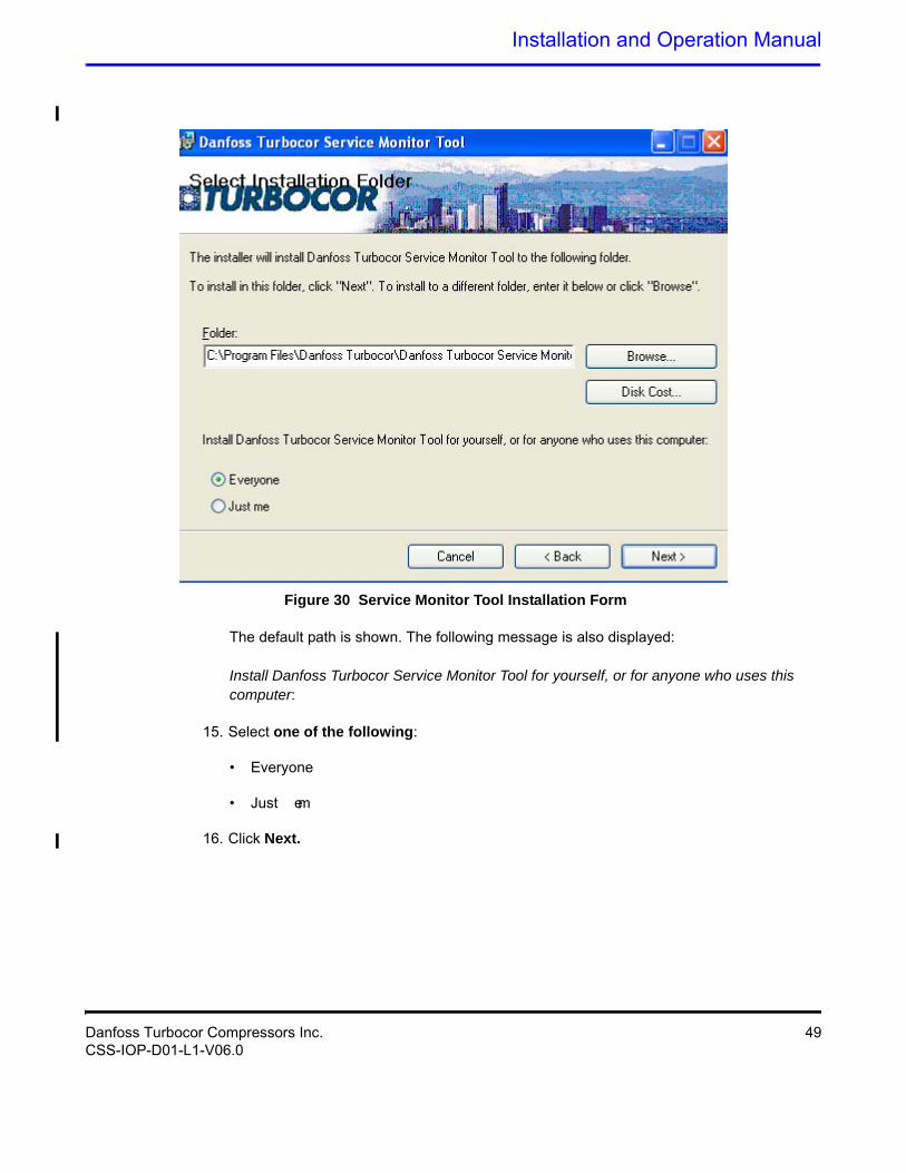
Figure 30 Service Monitor Tool Installation Form
The default path is shown. The following message is also displayed:
Install Danfoss Turbocor Service Monitor Tool for yourself, or for anyone who uses this computer:
15. Select one of the following:
• Everyone
• Just me
16. Click Next.
Danfoss Turbocor Compressors Inc. 49CSS-IOP-D01-L1-V06.0
Commissioning
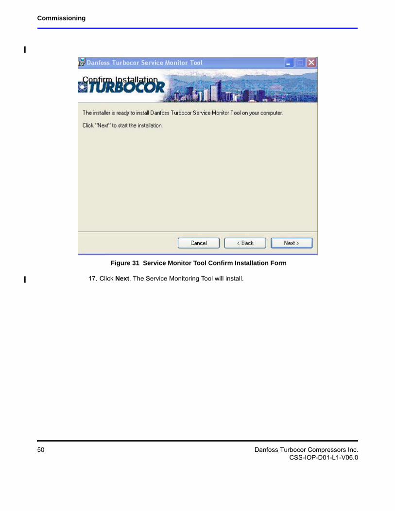
Figure 31 Service Monitor Tool Confirm Installation Form
17. Click Next. The Service Monitoring Tool will install.
50 Danfoss Turbocor Compressors Inc.CSS-IOP-D01-L1-V06.0
Installation and Operation Manual
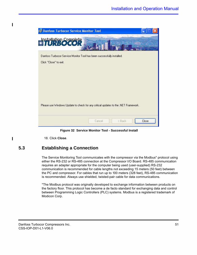
Figure 32 Service Monitor Tool - Successful Install
18. Click Close.
5.3 Establishing a Connection
The Service Monitoring Tool communicates with the compressor via the Modbus* protocol using either the RS-232 or RS-485 connection at the Compressor I/O Board. RS-485 communication requires an adapter appropriate for the computer being used (user-supplied) RS-232 communication is recommended for cable lengths not exceeding 15 meters (50 feet) between the PC and compressor. For cables that run up to 100 meters (328 feet), RS-485 communication is recommended. Always use shielded, twisted-pair cable for data communications.
*The Modbus protocol was originally developed to exchange information between products on the factory floor. This protocol has become a de facto standard for exchanging data and control between Programming Logic Controllers (PLC) systems. Modbus is a registered trademark of Modicon Corp.
Danfoss Turbocor Compressors Inc. 51CSS-IOP-D01-L1-V06.0
Commissioning
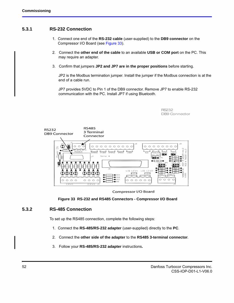
5.3.1 RS-232 Connection
1. Connect one end of the RS-232 cable (user-supplied) to the DB9 connector on the Compressor I/O Board (see Figure 33).
2. Connect the other end of the cable to an available USB or COM port on the PC. This may require an adapter.
3. Confirm that jumpers JP2 and JP7 are in the proper positions before starting.JP2 is the Modbus termination jumper. Install the jumper if the Modbus connection is at the end of a cable run.JP7 provides 5VDC to Pin 1 of the DB9 connector. Remove JP7 to enable RS-232 communication with the PC. Install JP7 if using Bluetooth.
Figure 33 RS-232 and RS485 Connectors - Compressor I/O Board
5.3.2 RS-485 Connection
To set up the RS485 connection, complete the following steps:
1. Connect the RS-485/RS-232 adapter (user-supplied) directly to the PC.
2. Connect the other side of the adapter to the RS485 3-terminal connector.
3. Follow your RS-485/RS-232 adapter instructions.
52 Danfoss Turbocor Compressors Inc.CSS-IOP-D01-L1-V06.0
Installation and Operation Manual
5.4 Service Monitoring Tool Basics
5.4.1 Starting the Service Monitoring Tool
To start the Monitoring Program: from the Start menu, select All Programs Danfoss Turbocor Service Monitoring Tool.
5.4.2 Entering User Input
When user input is required for the Service Monitoring Tool fields, perform the following sequence:
1. Click or double-click the variable field (or press Tab to step through).
2. Scroll or type in the new setting.
3. Press Enter.
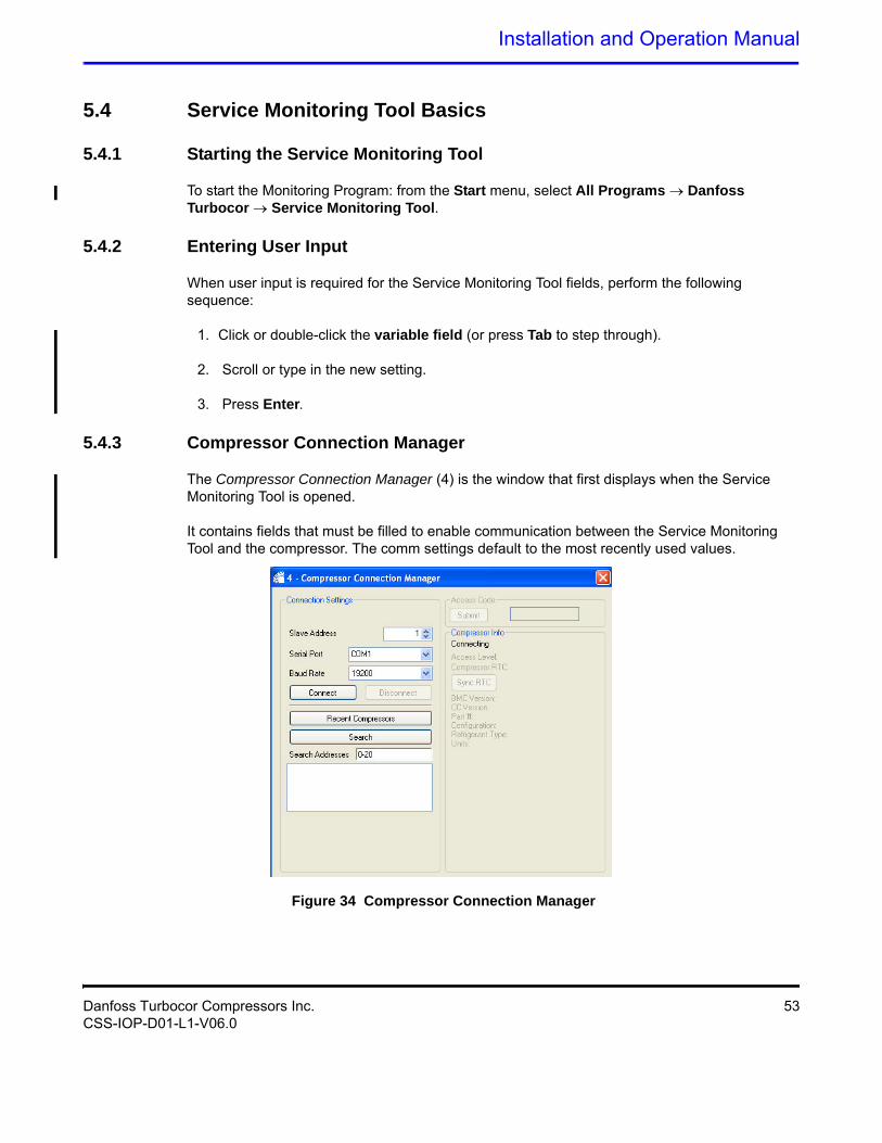
5.4.3 Compressor Connection Manager
The Compressor Connection Manager (4) is the window that first displays when the Service Monitoring Tool is opened.
It contains fields that must be filled to enable communication between the Service Monitoring Tool and the compressor. The comm settings default to the most recently used values.
Figure 34 Compressor Connection Manager
Danfoss Turbocor Compressors Inc. 53CSS-IOP-D01-L1-V06.0
Commissioning
To begin using the Service Monitoring Tool, complete the following steps:
1. Set the fields on the Compressor Connection Manager, or you can use the default values.
The fields are:
• Slave Address - 1-64. (1: default)
• Serial Port - Serial Communication Port that the computer will use to connect to the compressor. The serial ports listed reflect the names of the serial ports currently available on the host computer.
• Baud Rate -19,200 or 38,400 baud
2. To view recent compressors connected through the Service Monitoring Tool, click Recent Compressors. Select the compressor to connect.
3. To search for a compressor, enter the Search Addresses, and then click Search. Select the compressor to connect.
4. Click Connect to connect to the compressor.
The connection status and compressor details display in the lower right pane of the Compressor Connection Manager.
5. If necessary, change the access level. Enter the access code in the Access Code field, and then click Submit. Confirm that the correct access level is displayed in the right-hand pane of the Compressor Connection Manager.
5.4.4 Controlling User Access
The access code system allows OEM customers to set their own unique access codes, thereby restricting access to company-authorized personnel only.
These access codes control access to all adjustable parameters via the Modbus communications protocol. The access levels are:
• Level 1 - This level is “Read Only” and is intended for the plant operator, building maintenance personnel or owner. This is the default user level and no access code is required.
• Level 2 - This level allows minimal adjustments to be made such as leaving chilled water temp, display units, chiller enable/disable, etc. and is intended for the technician commissioning the compressor and performing limited fault-finding operations. A Basic Level User access code is required.
• Level 3 - This level allows most adjustments to be made such as operating the compressor in manual mode or calibrating the bearings and is intended for the OEM trained (certified) technician. An OEM Level User access code is required.
54 Danfoss Turbocor Compressors Inc.CSS-IOP-D01-L1-V06.0
Installation and Operation Manual
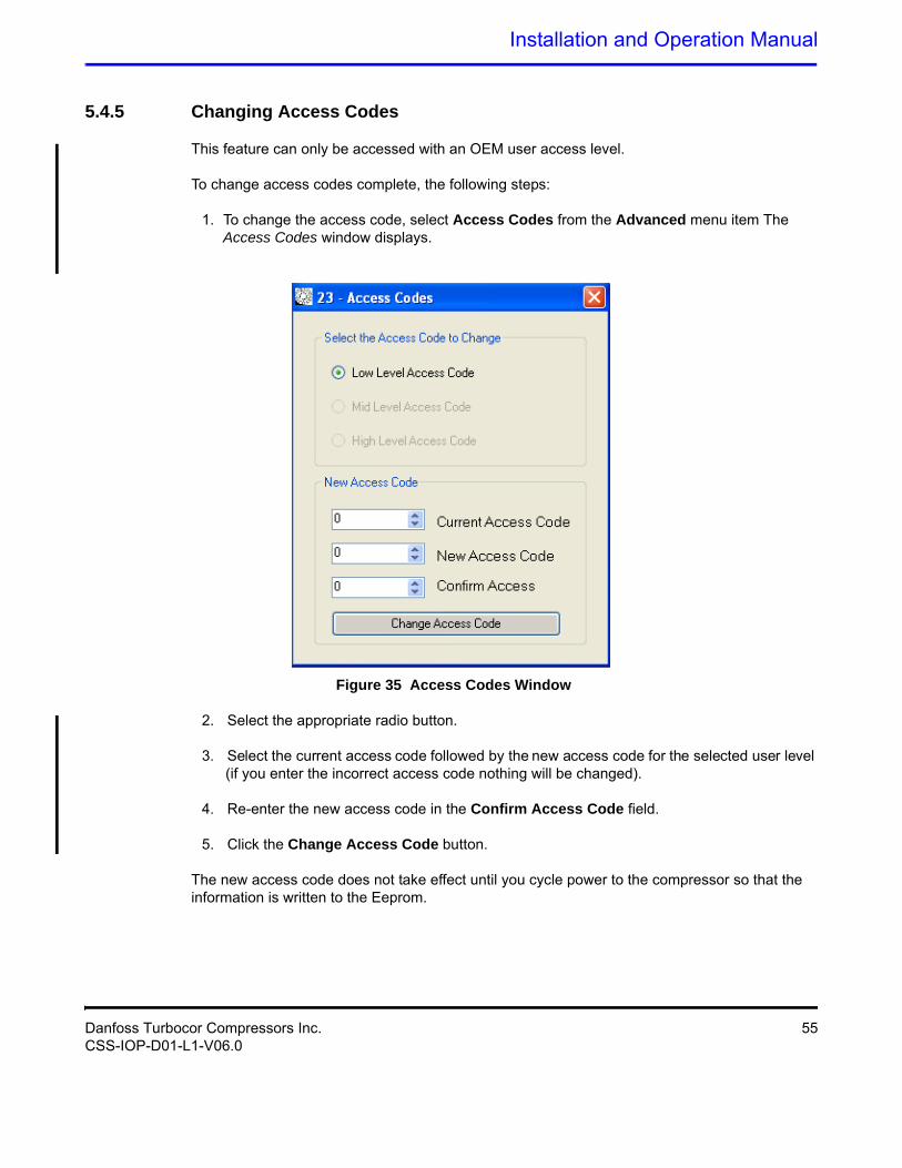
5.4.5 Changing Access Codes
This feature can only be accessed with an OEM user access level.
To change access codes complete, the following steps:
1. To change the access code, select Access Codes from the Advanced menu item The Access Codes window displays.
Figure 35 Access Codes Window
2. Select the appropriate radio button.
3. Select the current access code followed by the new access code for the selected user level (if you enter the incorrect access code nothing will be changed).
4. Re-enter the new access code in the Confirm Access Code field.
5. Click the Change Access Code button.
The new access code does not take effect until you cycle power to the compressor so that the information is written to the Eeprom.
Danfoss Turbocor Compressors Inc. 55CSS-IOP-D01-L1-V06.0
Commissioning
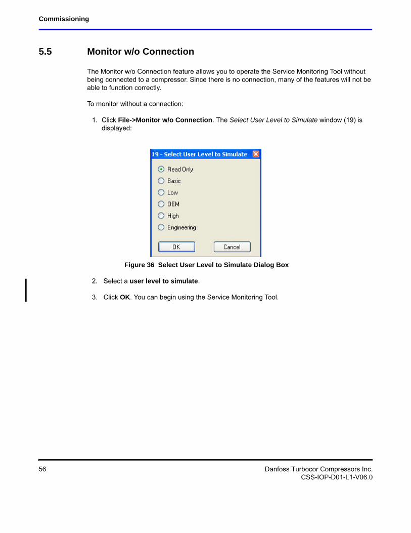
5.5 Monitor w/o Connection
The Monitor w/o Connection feature allows you to operate the Service Monitoring Tool without being connected to a compressor. Since there is no connection, many of the features will not be able to function correctly.
To monitor without a connection:
1. Click File->Monitor w/o Connection. The Select User Level to Simulate window (19) is displayed:
Figure 36 Select User Level to Simulate Dialog Box
2. Select a user level to simulate.
3. Click OK. You can begin using the Service Monitoring Tool.
56 Danfoss Turbocor Compressors Inc.CSS-IOP-D01-L1-V06.0
Installation and Operation Manual
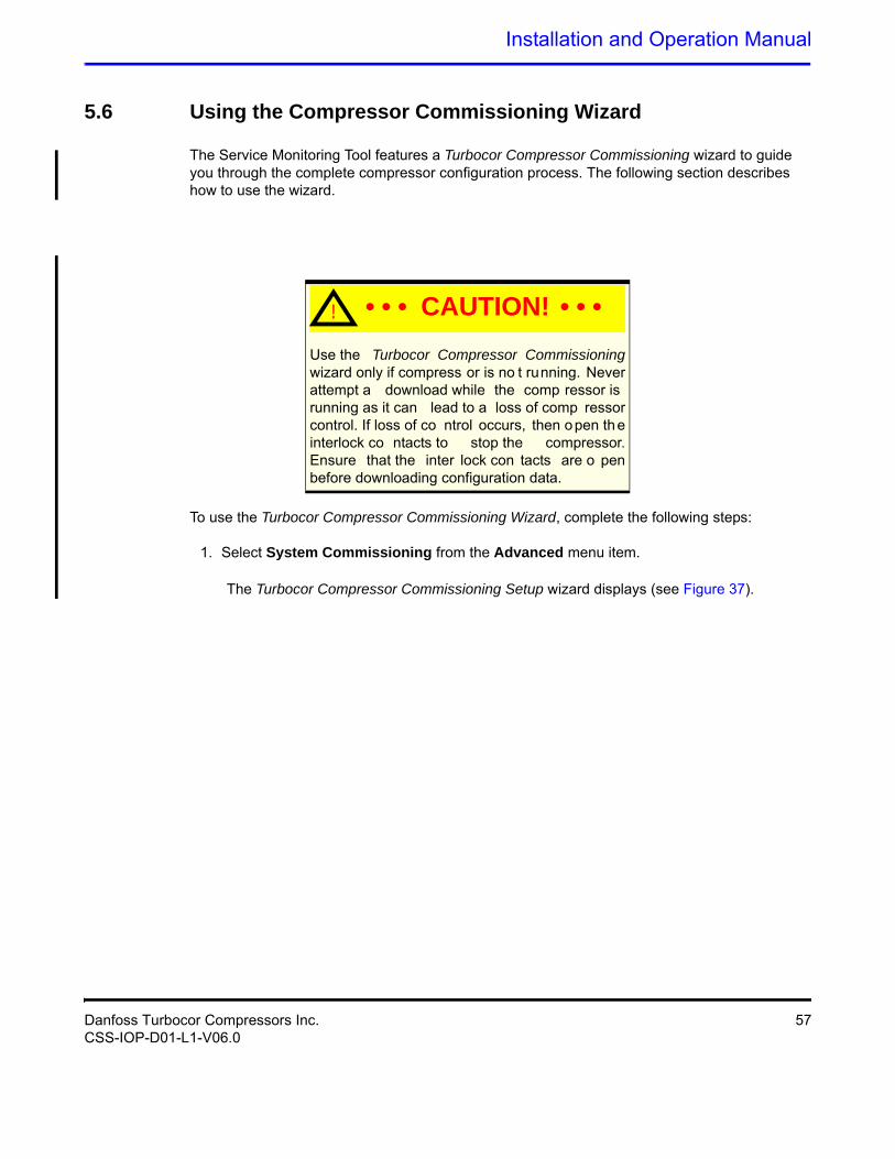
5.6 Using the Compressor Commissioning Wizard
The Service Monitoring Tool features a Turbocor Compressor Commissioning wizard to guide you through the complete compressor configuration process. The following section describes how to use the wizard.
Use the Turbocor Compressor Commissioning wizard only if compress or is no t running. Never attempt a download while the comp ressor is running as it can lead to a loss of comp ressor control. If loss of co ntrol occurs, then open the interlock co ntacts to stop the compressor. Ensure that the inter lock con tacts are o pen before downloading configuration data.
To use the Turbocor Compressor Commissioning Wizard, complete the following steps:
1. Select System Commissioning from the Advanced menu item.
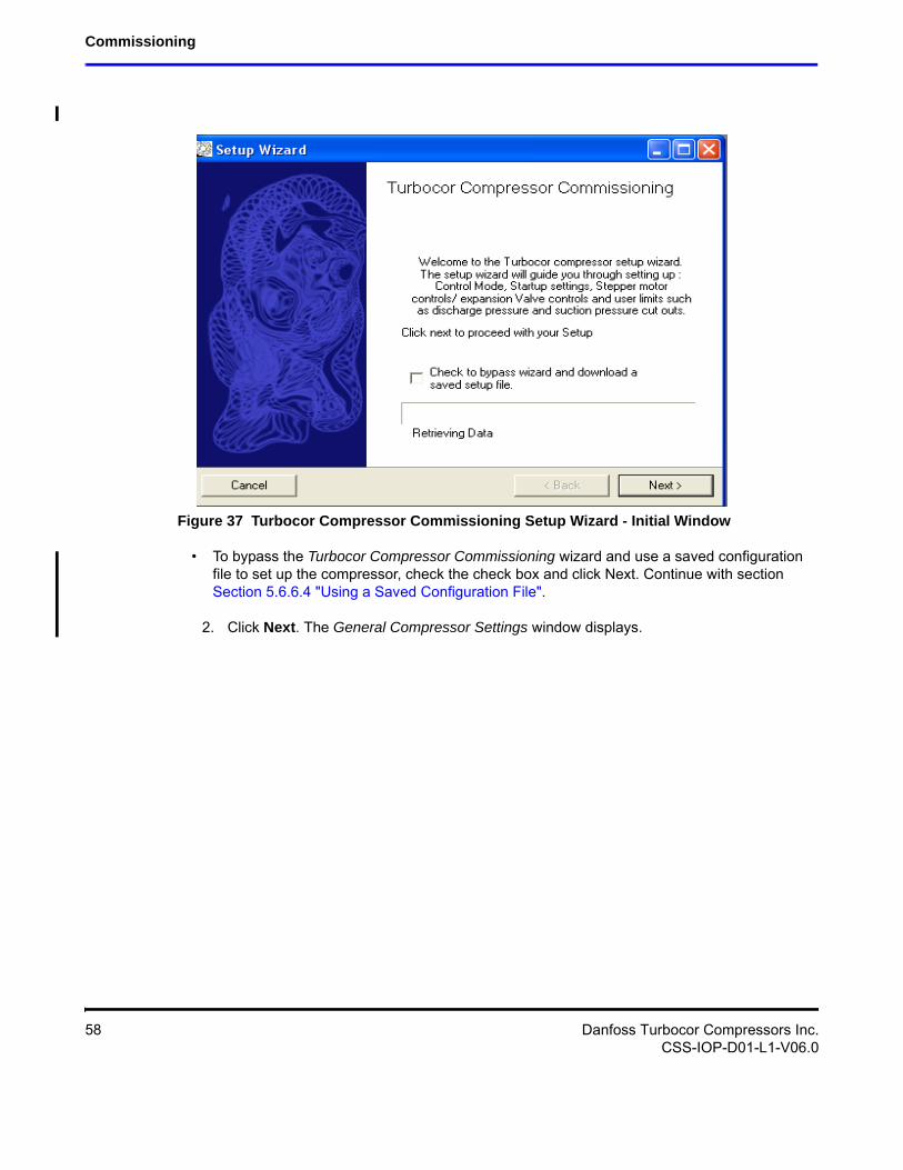
The Turbocor Compressor Commissioning Setup wizard displays (see Figure 37).
! • • • CAUTION! • • •
Danfoss Turbocor Compressors Inc. 57CSS-IOP-D01-L1-V06.0
Commissioning
Figure 37 Turbocor Compressor Commissioning Setup Wizard - Initial Window
• To bypass the Turbocor Compressor Commissioning wizard and use a saved configuration file to set up the compressor, check the check box and click Next. Continue with section Section 5.6.6.4 "Using a Saved Configuration File".
2. Click Next. The General Compressor Settings window displays.
58 Danfoss Turbocor Compressors Inc.CSS-IOP-D01-L1-V06.0
Installation and Operation Manual
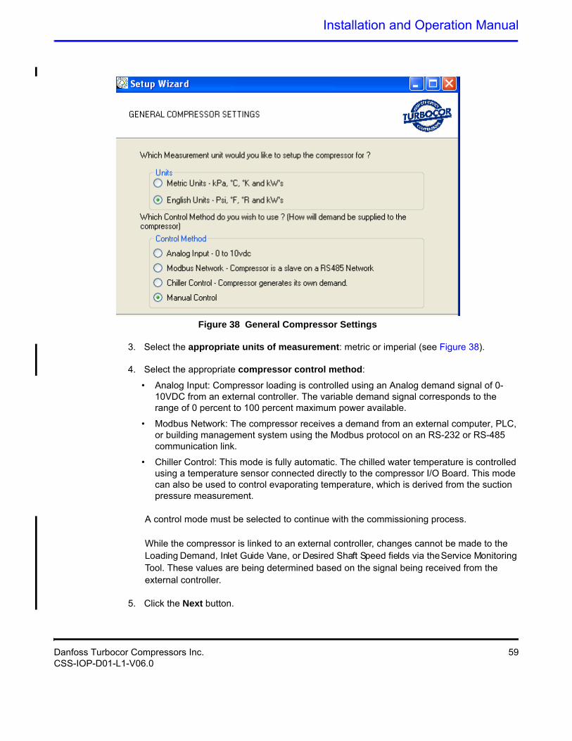
Figure 38 General Compressor Settings
3. Select the appropriate units of measurement: metric or imperial (see Figure 38).
4. Select the appropriate compressor control method:
• Analog Input: Compressor loading is controlled using an Analog demand signal of 0-10VDC from an external controller. The variable demand signal corresponds to the range of 0 percent to 100 percent maximum power available.
• Modbus Network: The compressor receives a demand from an external computer, PLC, or building management system using the Modbus protocol on an RS-232 or RS-485 communication link.
• Chiller Control: This mode is fully automatic. The chilled water temperature is controlled using a temperature sensor connected directly to the compressor I/O Board. This mode can also be used to control evaporating temperature, which is derived from the suction pressure measurement.
A control mode must be selected to continue with the commissioning process.
While the compressor is linked to an external controller, changes cannot be made to the Loading Demand, Inlet Guide Vane, or Desired Shaft Speed fields via the Service Monitoring Tool. These values are being determined based on the signal being received from the external controller.
5. Click the Next button.
Danfoss Turbocor Compressors Inc. 59CSS-IOP-D01-L1-V06.0
Commissioning
• If you selected Analog Input or Modbus Network as your control mode, jump to Section 5.6.2 "Startup Settings".
• If you selected Chiller Control Mode, proceed to Section 5.6.1 "Chiller Control Mode".
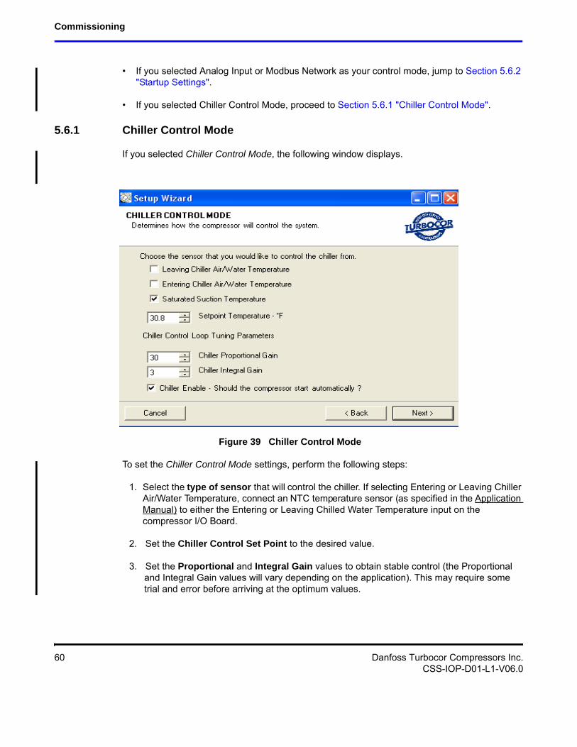
5.6.1 Chiller Control Mode
If you selected Chiller Control Mode, the following window displays.
Figure 39 Chiller Control Mode
To set the Chiller Control Mode settings, perform the following steps:
1. Select the type of sensor that will control the chiller. If selecting Entering or Leaving Chiller Air/Water Temperature, connect an NTC temperature sensor (as specified in the Application Manual) to either the Entering or Leaving Chilled Water Temperature input on the compressor I/O Board.
2. Set the Chiller Control Set Point to the desired value.
3. Set the Proportional and Integral Gain values to obtain stable control (the Proportional and Integral Gain values will vary depending on the application). This may require some trial and error before arriving at the optimum values.
60 Danfoss Turbocor Compressors Inc.CSS-IOP-D01-L1-V06.0
Installation and Operation Manual
The Integral part of the internal chiller controller is switched off until the compressor reaches a speed of 18,500 RPMs. Stopping the compressor and restarting also resets the Integral part to 0.
4. Click in the Chiller Enable check box to activate chiller control mode. Ensure that the Interlock contact (located on the compressor I/O Board is open to prevent the compressor from starting before the commissioning sequence is complete.
5. Click Next.
6. Proceed to Section 5.6.2 "Startup Settings".
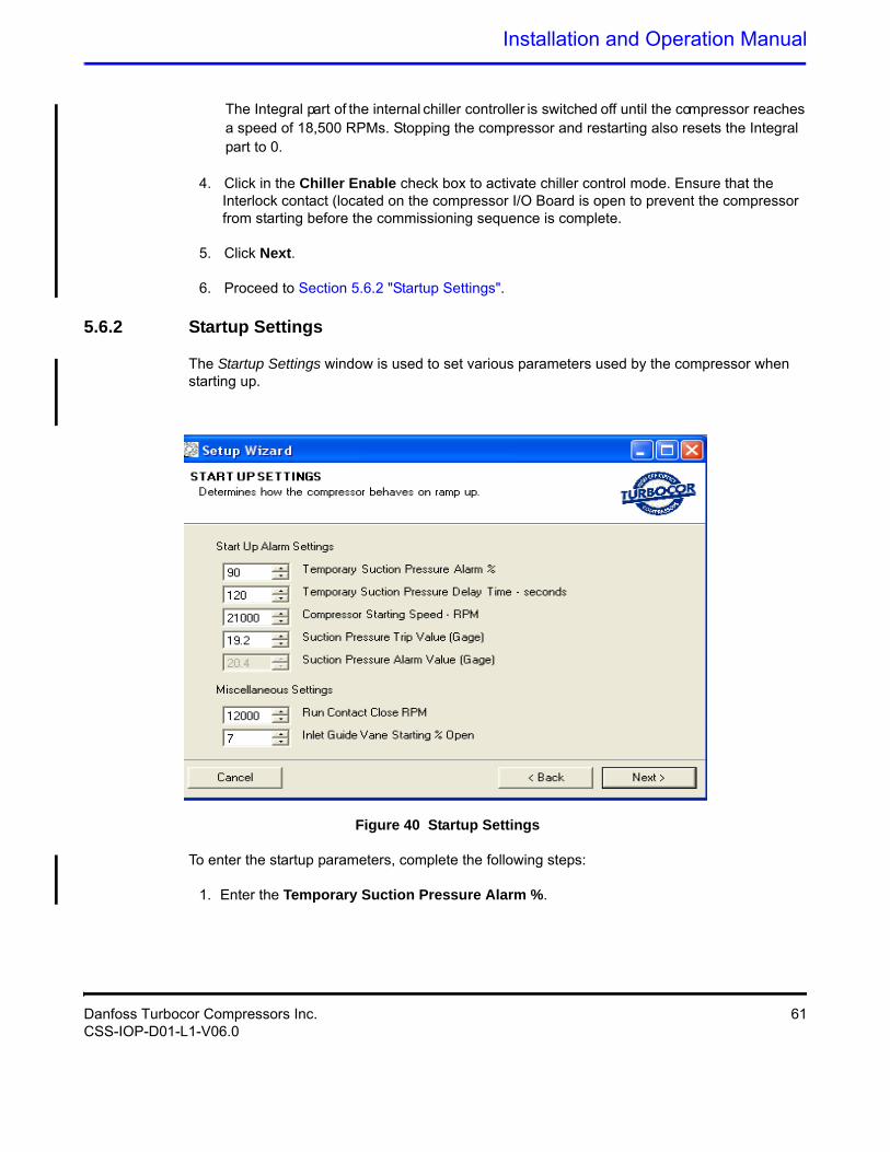
5.6.2 Startup Settings
The Startup Settings window is used to set various parameters used by the compressor when starting up.
Figure 40 Startup Settings
To enter the startup parameters, complete the following steps:
1. Enter the Temporary Suction Pressure Alarm %.
Danfoss Turbocor Compressors Inc. 61CSS-IOP-D01-L1-V06.0
Commissioning
The Temporary Suction Pressure Alarm % is a percentage of the existing Suction Pressure Limit in the Eeprom. For example, if a suction pressure trip of 270 kPa was set and the temporary suction pressure alarm was set to 50 percent, the temporary suction pressure trip limit would be 135 kPa. This temporary alarm is only active while the Suction Pressure Delay timer is counting down.
2. Enter the Temporary Suction Pressure Delay Time.
The Temporary Suction Pressure Delay Time parameter represents the time in seconds that the temporary suction pressure alarm % is in effect. The timer starts to count down when the drive is enabled.
3. Enter the Compressor Starting Speed.
If the estimated minimum speed is greater than the starting speed setting, the compressor will ramp up to the estimated minimum speed. If the starting speed setting is greater than the estimated minimum speed, the compressor will ramp up to the starting speed. In both cases, the compressor speed will increase at the full ramp rate.
4. Enter the Run Contact Close RPM.
The compressor Serial Driver contains a normally open (NO) relay contact that closes while the compressor is running. The speed at which the contact closes is determined by the Run Contact Close RPM.
5. Enter the Inlet Guide Vane Starting % Open.
Typically the IGV Starting % Open should be a minimum of 25% and usually 50-70% is optimal to prevent check valve chatter.
6. Click Next to continue.
62 Danfoss Turbocor Compressors Inc.CSS-IOP-D01-L1-V06.0
Installation and Operation Manual
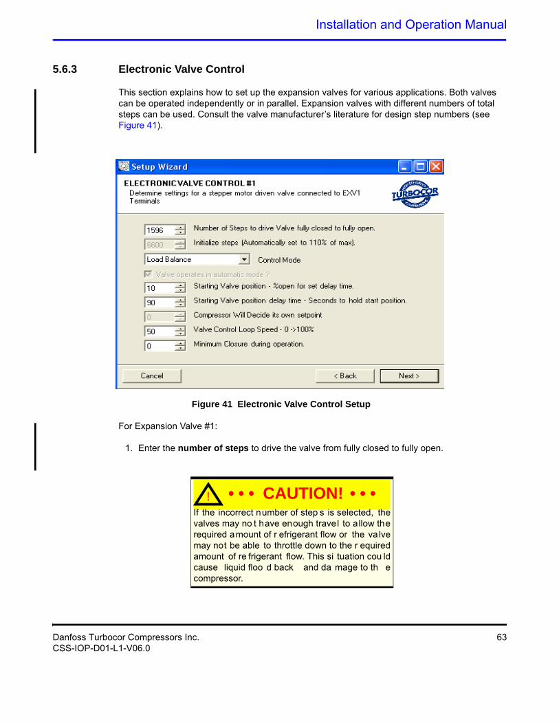
5.6.3 Electronic Valve Control
This section explains how to set up the expansion valves for various applications. Both valves can be operated independently or in parallel. Expansion valves with different numbers of total steps can be used. Consult the valve manufacturer’s literature for design step numbers (see Figure 41).
Figure 41 Electronic Valve Control Setup
For Expansion Valve #1:
1. Enter the number of steps to drive the valve from fully closed to fully open.
! • • • CAUTION! • • •If the incorrect number of step s is selected, the valves may no t have enough travel to allow the required amount of r efrigerant flow or the va lve may not be able to throttle down to the r equired amount of re frigerant flow. This si tuation cou ld cause liquid floo d back and da mage to th e compressor.
Danfoss Turbocor Compressors Inc. 63CSS-IOP-D01-L1-V06.0
Commissioning
2. Select the control mode for the expansion valve. Available options are: superheat, liquid level, or load balance. See Table 8 for a description of the modes.
3. Enter the Starting Valve Position %. If desired, at compressor startup, the valves can be set to open to a pre-start value for a given time.
This value represents the percentage of maximum steps and is sent to the motor when the shaft starts to rotate. The stepper motor will hold at this position until the stepper start delay timer has expired.
4. Enter the Valve Starting Position Delay Time. This parameter represents the time in seconds that the starting valve position is in effect. The timer starts to count down when the drive is enabled.
5. Enter the Control Setpoint (suction superheat or Liquid level % in accordance with the control mode selected. Not applicable to load balance control mode as compressor fixes best position.).
6. Enter the Valve Control Loop Speed. This value represents the reaction time of the control loop to a process error and replaces the PID (proportional, integral, and derivative) controller gains.
7. Enter the Minimum Closure During Operation. This is the minimum close position for the valve while the compressor is in operation.
8. Click Next to continue. Repeat steps 1 through 7 for electronic expansion valve # 2.
9. Click Next to go to Analog Output setup. See Section 5.6.4 "Analog Output Setup".
64 Danfoss Turbocor Compressors Inc.CSS-IOP-D01-L1-V06.0
Installation and Operation Manual
.
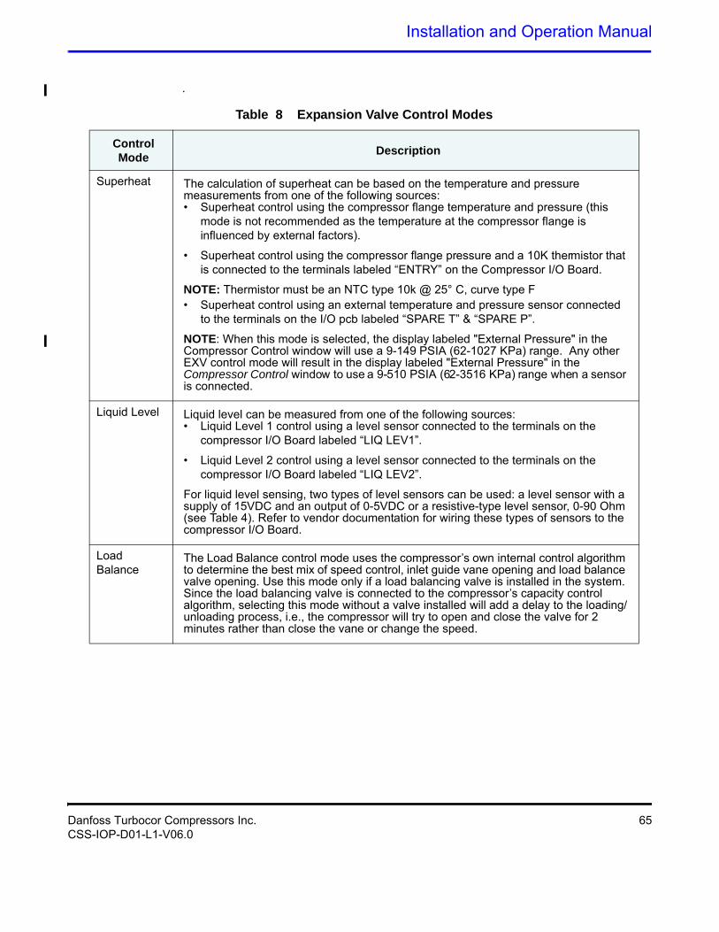
Table 8 Expansion Valve Control Modes
Control Mode
Description
Superheat The calculation of superheat can be based on the temperature and pressure measurements from one of the following sources:
NOTE: Thermistor must be an NTC type 10k @ 25° C, curve type F
NOTE: When this mode is selected, the display labeled "External Pressure" in the Compressor Control window will use a 9-149 PSIA (62-1027 KPa) range. Any other EXV control mode will result in the display labeled "External Pressure" in the Compressor Control window to use a 9-510 PSIA (62-3516 KPa) range when a sensor is connected.
Liquid Level Liquid level can be measured from one of the following sources:
For liquid level sensing, two types of level sensors can be used: a level sensor with a supply of 15VDC and an output of 0-5VDC or a resistive-type level sensor, 0-90 Ohm (see Table 4). Refer to vendor documentation for wiring these types of sensors to the compressor I/O Board.
Load Balance
The Load Balance control mode uses the compressor’s own internal control algorithm to determine the best mix of speed control, inlet guide vane opening and load balance valve opening. Use this mode only if a load balancing valve is installed in the system. Since the load balancing valve is connected to the compressor’s capacity control algorithm, selecting this mode without a valve installed will add a delay to the loading/unloading process, i.e., the compressor will try to open and close the valve for 2 minutes rather than close the vane or change the speed.
• Superheat control using the compressor flange temperature and pressure (this mode is not recommended as the temperature at the compressor flange is influenced by external factors).
• Superheat control using the compressor flange pressure and a 10K thermistor that is connected to the terminals labeled “ENTRY” on the Compressor I/O Board.
• Superheat control using an external temperature and pressure sensor connected to the terminals on the I/O pcb labeled “SPARE T” & “SPARE P”.
• Liquid Level 1 control using a level sensor connected to the terminals on the compressor I/O Board labeled “LIQ LEV1”.
• Liquid Level 2 control using a level sensor connected to the terminals on the compressor I/O Board labeled “LIQ LEV2”.
Danfoss Turbocor Compressors Inc. 65CSS-IOP-D01-L1-V06.0
Commissioning
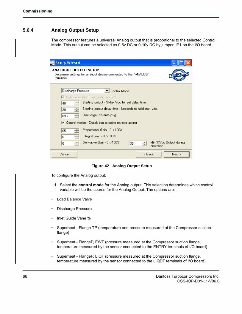
5.6.4 Analog Output Setup
The compressor features a universal Analog output that is proportional to the selected Control Mode. This output can be selected as 0-5v DC or 0-10v DC by jumper JP1 on the I/O board.
Figure 42 Analog Output Setup
To configure the Analog output:
1. Select the control mode for the Analog output. This selection determines which control variable will be the source for the Analog Output. The options are:
• Load Balance Valve
• Discharge Pressure
• Inlet Guide Vane %
• Superheat - Flange TP (temperature and pressure measured at the Compressor suction flange)
• Superheat - FlangeP, EWT (pressure measured at the Compressor suction flange, temperature measured by the sensor connected to the ENTRY terminals of I/O board)
• Superheat - FlangeP, LIQT (pressure measured at the Compressor suction flange, temperature measured by the sensor connected to the LIQDT terminals of I/O board)
66 Danfoss Turbocor Compressors Inc.CSS-IOP-D01-L1-V06.0
Installation and Operation Manual
• Suction Pressure.
• Leaving Temp (temperature measured by the sensor connected to the LEAVE terminals of I/O board)
• Entering Temp (pressure measured at the Compressor suction flange, temperature by the sensor connected to the ENTRY terminals of I/O board)
• Liquid Temp (temperature measured by the sensor connected to the LIQDT terminals of I/O board)
2. Enter the Starting Output. This value equals the percentage of maximum voltage sent to the Analog terminals (JP1) on the compressor I/O Board. The Analog output will hold at this position until the start delay timer has expired.
3. Enter Starting Output Delay Time.This parameter represents the time in seconds that the starting output is in effect The timer starts to count down when the drive is enabled.
4. Check the Control Action check box for reverse acting. Leaving the check box unchecked will enable direct acting.
5. Enter the Proportional, Integral, and Derivative gains to provide stable control. These gain values may require some trial and error to achieve optimum result.
6. Enter the minimum Analog output %. This parameter can be used to maintain a minimum valve % open.
This value is a percentage of the total VDC. This parameter can be used, for example, to maintain a minimum valve open position during operation.
Danfoss Turbocor Compressors Inc. 67CSS-IOP-D01-L1-V06.0
Commissioning
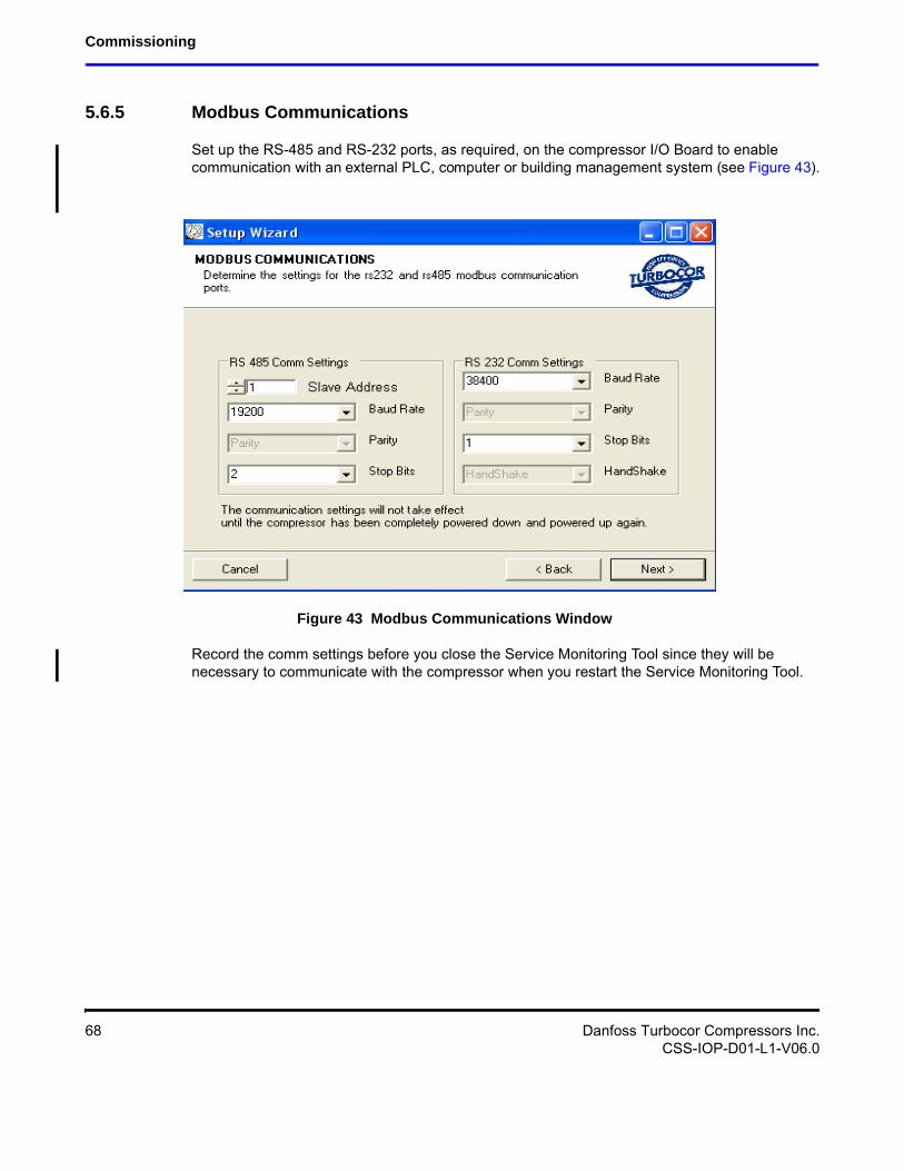
5.6.5 Modbus Communications
Set up the RS-485 and RS-232 ports, as required, on the compressor I/O Board to enable communication with an external PLC, computer or building management system (see Figure 43).
Figure 43 Modbus Communications Window
Record the comm settings before you close the Service Monitoring Tool since they will be necessary to communicate with the compressor when you restart the Service Monitoring Tool.
68 Danfoss Turbocor Compressors Inc.CSS-IOP-D01-L1-V06.0
Installation and Operation Manual
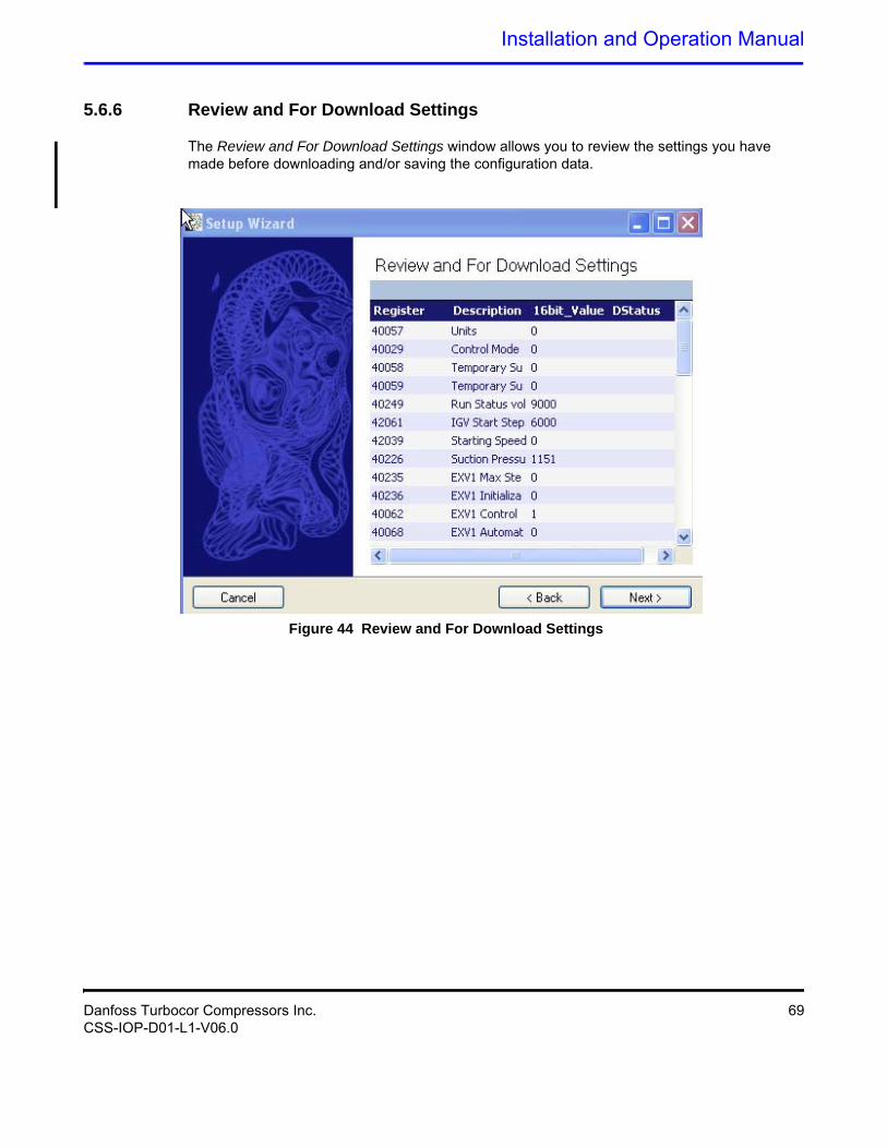
5.6.6 Review and For Download Settings
The Review and For Download Settings window allows you to review the settings you have made before downloading and/or saving the configuration data.
Figure 44 Review and For Download Settings
Danfoss Turbocor Compressors Inc. 69CSS-IOP-D01-L1-V06.0
Commissioning
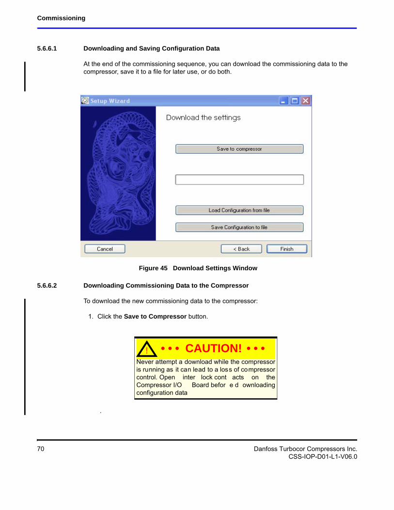
5.6.6.1 Downloading and Saving Configuration Data
At the end of the commissioning sequence, you can download the commissioning data to the compressor, save it to a file for later use, or do both.
Figure 45 Download Settings Window
5.6.6.2 Downloading Commissioning Data to the Compressor
To download the new commissioning data to the compressor:
1. Click the Save to Compressor button.
.
! • • • CAUTION! • • •Never attempt a download while the compressor is running as it can lead to a loss of compressor control. Open inter lock cont acts on the Compressor I/O Board befor e d ownloading configuration data
70 Danfoss Turbocor Compressors Inc.CSS-IOP-D01-L1-V06.0
Installation and Operation Manual
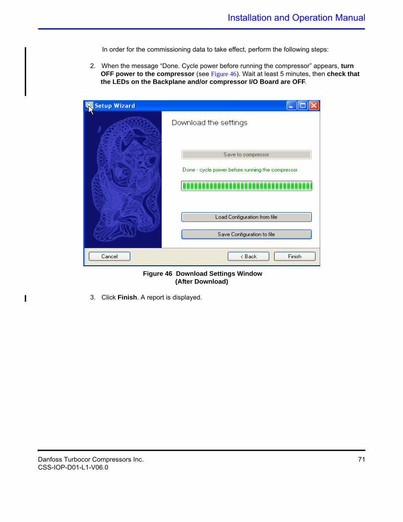
In order for the commissioning data to take effect, perform the following steps:
2. When the message “Done. Cycle power before running the compressor” appears, turn OFF power to the compressor (see Figure 46). Wait at least 5 minutes, then check that the LEDs on the Backplane and/or compressor I/O Board are OFF.
Figure 46 Download Settings Window (After Download)
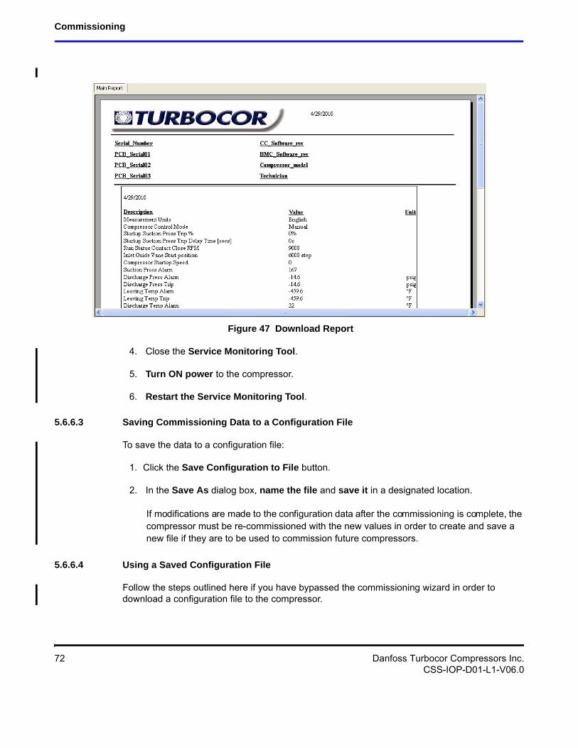
3. Click Finish. A report is displayed.
Danfoss Turbocor Compressors Inc. 71CSS-IOP-D01-L1-V06.0
Commissioning
Figure 47 Download Report
4. Close the Service Monitoring Tool.
5. Turn ON power to the compressor.
6. Restart the Service Monitoring Tool.
5.6.6.3 Saving Commissioning Data to a Configuration File
To save the data to a configuration file:
1. Click the Save Configuration to File button.
2. In the Save As dialog box, name the file and save it in a designated location.
If modifications are made to the configuration data after the commissioning is complete, the compressor must be re-commissioned with the new values in order to create and save a new file if they are to be used to commission future compressors.
5.6.6.4 Using a Saved Configuration File
Follow the steps outlined here if you have bypassed the commissioning wizard in order to download a configuration file to the compressor.
72 Danfoss Turbocor Compressors Inc.CSS-IOP-D01-L1-V06.0
Installation and Operation Manual
1. Click the Load Configuration From File button; see Section 5.6.6.4 "Using a Saved Configuration File".
2. In the Open File dialog box, browse to the location of the configuration (.ttc) file.
3. Click Open.
4. Click Download to Compressor button.
5. When the message “Done. Cycle power before running the compressor” appears, turn OFF power to the compressor (see Figure 46). Wait at least 5 minutes, then check that the LEDs on the Backplane and/or Compressor I/O Board are OFF.
6. Close the Service Monitoring Tool.
7. Turn ON power to the compressor.
8. Restart the Service Monitoring Tool.
5.7 Running Checks
This section contains the running checks that should be performed following compressor configuration.
1. Disable Power. Remove the mains input cover. Enable power. Using a voltmeter, check the line voltages at the Compressor terminals and verify that they match the display readings (under the heading of Soft Start Data on the VSPMM form of the Service Monitoring Tool). Disable power. Replace the mains input cover. Enable power.
2. If necessary, clear alarms, before running the compressor.
3. Start compressor. (Refer to the Service Monitoring Tool User Manual for instructions on starting the compressor in various modes).
4. Using a pressure gauge, check the suction and discharge pressures and verify that they match the display readings. If the compressor is equipped with the economizer option, also check the intermediate pressure.
! • • • CAUTION! • • •Never attempt a download while the compressor is running as it can lead to a loss of compressor control. Open inter lock cont acts on the Compressor I/O Board befor e d ownloading configuration data.
Danfoss Turbocor Compressors Inc. 73CSS-IOP-D01-L1-V06.0
Commissioning
5. Using a temperature probe, check the suction and discharge temperatures and verify that they match the display readings.
6. Ensure that operational temperatures and pressures are as per application.
NOTEAfter the compressor has been operating for 100 hours at 80 percent to 100 percent load, remove the suction strainer.
74 Danfoss Turbocor Compressors Inc.CSS-IOP-D01-L1-V06.0
Installation and Operation Manual
6 Functional Description
6.1 Compressor Fundamentals
Compressor operation begins with a call for cooling from a chiller controller or from the compressor itself in the chiller control mode. The compressor controller then begins compressor spin-up.
6.1.1 Main Fluid Path
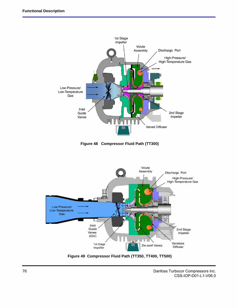
The following paragraphs describe the flow of refrigerant from the intake to the discharge port of the compressor (see Figure 48 and Figure 49).
The refrigerant enters the suction side of the compressor as a low-pressure, low-temperature, super-heated gas. The refrigerant gas passes through a set of adjustable Inlet Guide Vanes (IGVs) that are used to control the compressor capacity at low-load conditions. The first compression element the gas encounters is the first-stage impeller. The centrifugal force produced by the rotating impeller results in an increase in both gas velocity and pressure. The high-velocity gas discharging from the impeller is directed to the second-stage impeller through de-swirl vanes. The gas is further compressed by the second-stage impeller and then discharged through a volute via a diffuser (a volute is a curved funnel increasing in area to the discharge port. As the area of the cross-section increases, the volute reduces the speed of the gas and increases its pressure). From there, the high-pressure/high-temperature gas exits the compressor at the discharge port.
Danfoss Turbocor Compressors Inc. 75CSS-IOP-D01-L1-V06.0
Functional Description
Figure 48 Compressor Fluid Path (TT300)
Figure 49 Compressor Fluid Path (TT350, TT400, TT500)
76 Danfoss Turbocor Compressors Inc.CSS-IOP-D01-L1-V06.0
Installation and Operation Manual
6.1.2 Motor Cooling
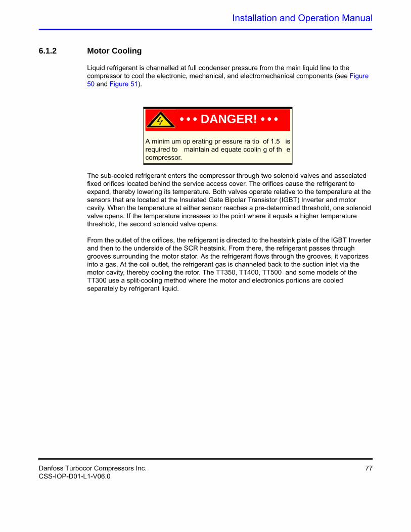
Liquid refrigerant is channelled at full condenser pressure from the main liquid line to the compressor to cool the electronic, mechanical, and electromechanical components (see Figure 50 and Figure 51).
A minim um op erating pr essure ra tio of 1.5 is required to maintain ad equate coolin g of th e compressor.
The sub-cooled refrigerant enters the compressor through two solenoid valves and associated fixed orifices located behind the service access cover. The orifices cause the refrigerant to expand, thereby lowering its temperature. Both valves operate relative to the temperature at the sensors that are located at the Insulated Gate Bipolar Transistor (IGBT) Inverter and motor cavity. When the temperature at either sensor reaches a pre-determined threshold, one solenoid valve opens. If the temperature increases to the point where it equals a higher temperature threshold, the second solenoid valve opens.
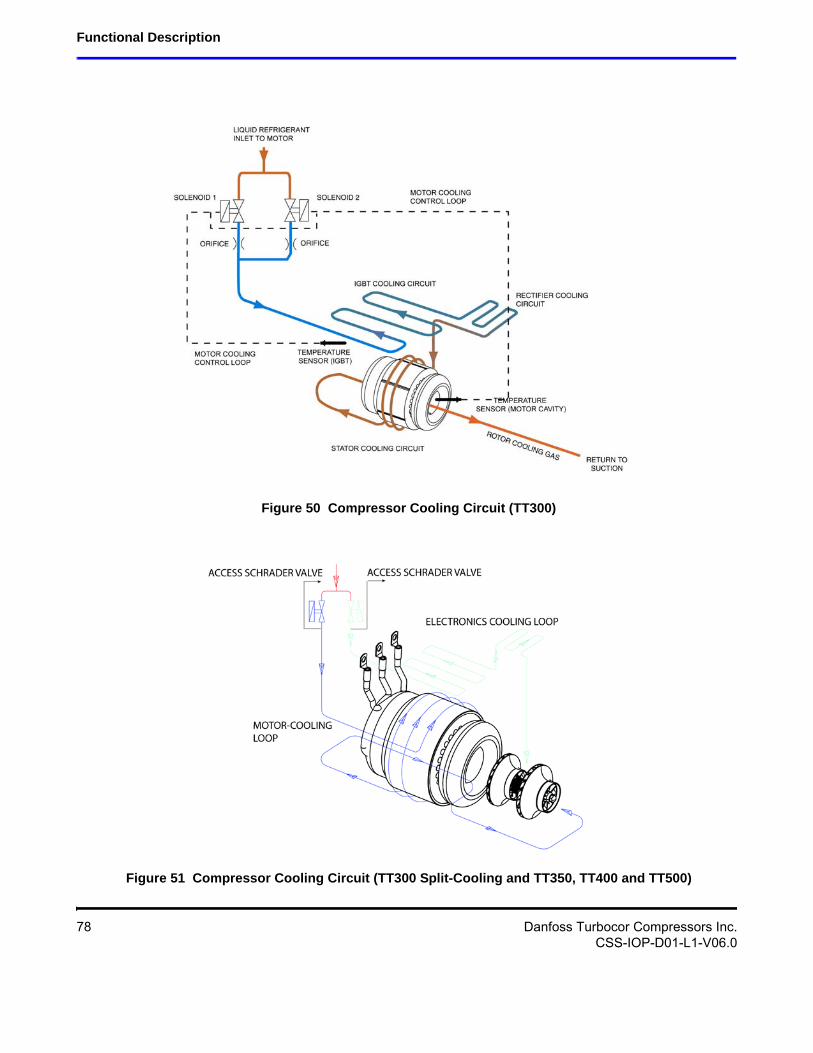
From the outlet of the orifices, the refrigerant is directed to the heatsink plate of the IGBT Inverter and then to the underside of the SCR heatsink. From there, the refrigerant passes through grooves surrounding the motor stator. As the refrigerant flows through the grooves, it vaporizes into a gas. At the coil outlet, the refrigerant gas is channeled back to the suction inlet via the motor cavity, thereby cooling the rotor. The TT350, TT400, TT500 and some models of the TT300 use a split-cooling method where the motor and electronics portions are cooled separately by refrigerant liquid.
• • • DANGER! • • •
Danfoss Turbocor Compressors Inc. 77CSS-IOP-D01-L1-V06.0
Functional Description
Figure 50 Compressor Cooling Circuit (TT300)
Figure 51 Compressor Cooling Circuit (TT300 Split-Cooling and TT350, TT400 and TT500)
78 Danfoss Turbocor Compressors Inc.CSS-IOP-D01-L1-V06.0
Installation and Operation Manual
6.1.3 Inlet Guide Vanes
The Inlet Guide Vane (IGV) assembly is a variable-angle guiding device that pre-rotates refrigerant flow at the compressor intake and is also used for capacity control. The IGV assembly consists of movable vanes and a motor. The vane angle, and hence, the degree of pre-rotation to the refrigerant flow is determined by the BMCC and controlled by the Serial Driver. The IGV position can vary between approximately 0-percent and 110-percent open.
6.2 Compressor Control Overview
Figure 52 shows a functional block diagram of the compressor control and monitoring system. Figure 53 displays the component locations. The major components include:
• Motor Drive
• Soft-Start Board
• Bearing Motor Compressor Controller (BMCC)
• Bearing PWM Amplifier
• Backplane
• Serial Driver
• HV DC-DC Converter
Danfoss Turbocor Compressors Inc. 79CSS-IOP-D01-L1-V06.0
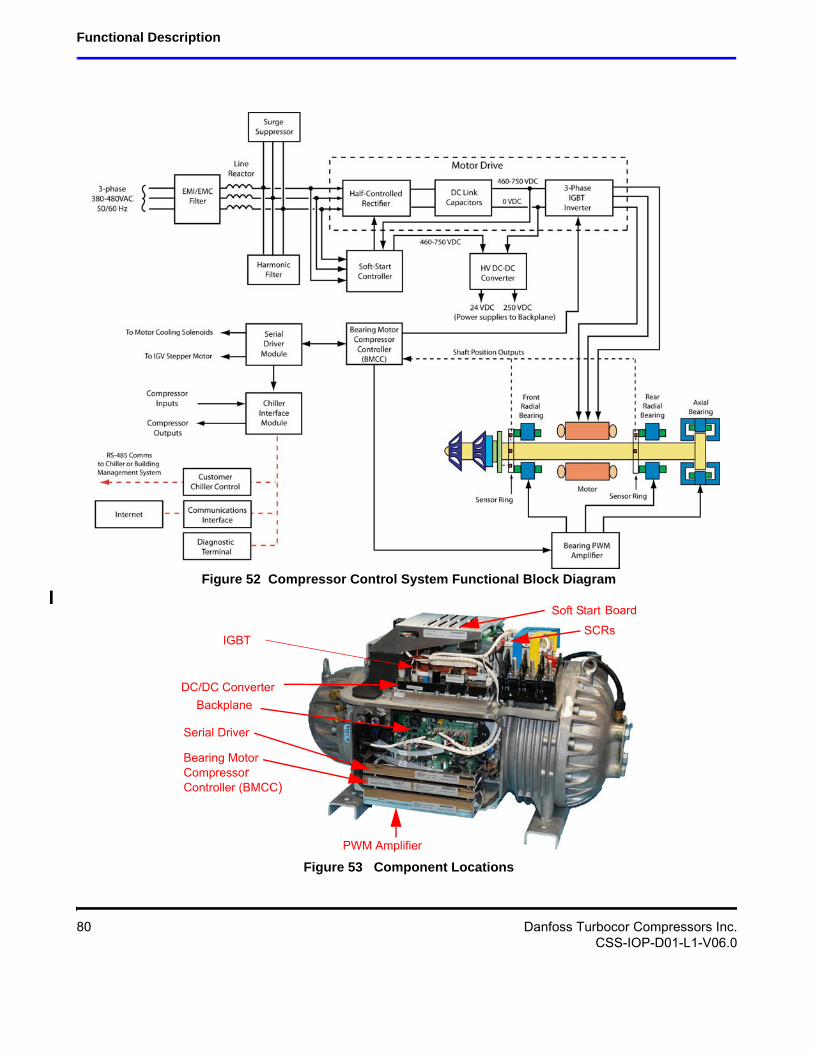
Functional Description
Figure 52 Compressor Control System Functional Block Diagram
PWM Amplifier
Bearing MotorCompressorController (BMCC)
Serial Driver
Backplane
Soft Start Board
IGBT
DC/DC Converter
SCRs
Figure 53 Component Locations
80 Danfoss Turbocor Compressors Inc.CSS-IOP-D01-L1-V06.0
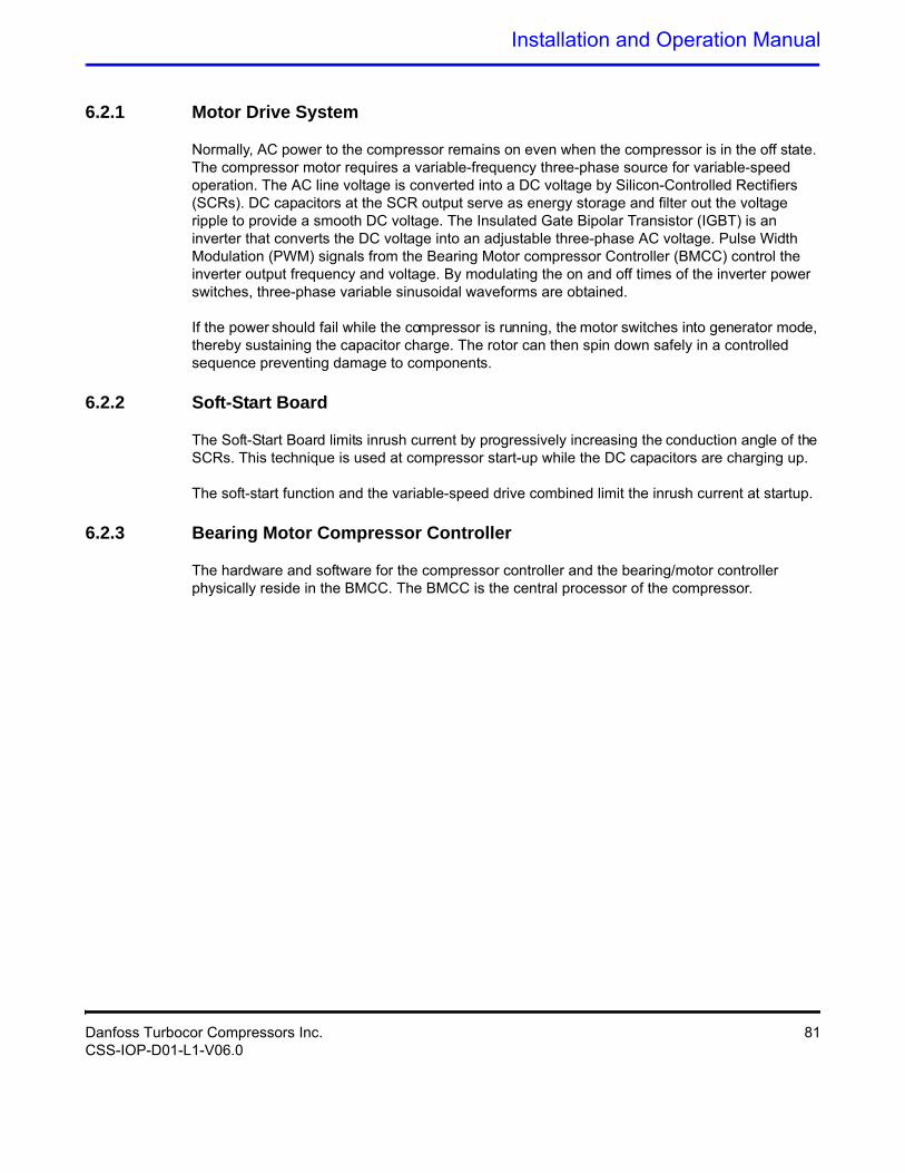
Installation and Operation Manual
6.2.1 Motor Drive System
Normally, AC power to the compressor remains on even when the compressor is in the off state. The compressor motor requires a variable-frequency three-phase source for variable-speed operation. The AC line voltage is converted into a DC voltage by Silicon-Controlled Rectifiers (SCRs). DC capacitors at the SCR output serve as energy storage and filter out the voltage ripple to provide a smooth DC voltage. The Insulated Gate Bipolar Transistor (IGBT) is an inverter that converts the DC voltage into an adjustable three-phase AC voltage. Pulse Width Modulation (PWM) signals from the Bearing Motor compressor Controller (BMCC) control the inverter output frequency and voltage. By modulating the on and off times of the inverter power switches, three-phase variable sinusoidal waveforms are obtained.
If the power should fail while the compressor is running, the motor switches into generator mode, thereby sustaining the capacitor charge. The rotor can then spin down safely in a controlled sequence preventing damage to components.
6.2.2 Soft-Start Board
The Soft-Start Board limits inrush current by progressively increasing the conduction angle of the SCRs. This technique is used at compressor start-up while the DC capacitors are charging up.
The soft-start function and the variable-speed drive combined limit the inrush current at startup.
6.2.3 Bearing Motor Compressor Controller
The hardware and software for the compressor controller and the bearing/motor controller physically reside in the BMCC. The BMCC is the central processor of the compressor.
Danfoss Turbocor Compressors Inc. 81CSS-IOP-D01-L1-V06.0
Functional Description
6.2.3.1 Compressor Control
The Compressor Controller is continuously updated with critical data from external sensors that indicate the compressor’s operating status. Under program control, the compressor controller can respond to changing conditions and requirements to ensure optimum system performance.
Figure 54 to Figure 59 shows how the controller responds to chiller demands.
6.2.3.2 Capacity Control
One of the Compressor Controller’s primary functions is to control the compressor’s motor speed and IGV position in order to satisfy load requirements and to avoid surge and choke conditions. However, the majority of capacity control can be achieved via motor speed.
6.2.3.3 Expansion Valve Control
The on-board Electronic Expansion Valve (EXV) controller uses a simplified loop gain to control the response characteristics of the valve. The valve opening is determined by either superheat or liquid level sensing.
Depending on the application, a load balancing (hot gas bypass) valve can be driven by the auxiliary EXV output. Load balancing allows the compressor to obtain lower capacities at higher pressure ratios. The valve opens to lower the overall pressure ratio and thereby reduces the lift, enabling the compressor to reduce speed/unload.
6.2.3.4 Motor/Bearing Control
The magnetic bearing system physically supports a rotating shaft while enabling non-contact between the shaft and surrounding stationary surfaces.
A digital bearing controller and motor controller provide the PWM command signals to the Bearing PWM Amplifier and IGBT Inverter, respectively.
The bearing controller also collects shaft position inputs from sensors and uses the feedback to calculate and maintain the desired shaft position.
6.2.3.5 Monitoring Functions
The compressor controller monitors more than 60 parameters, including:
• Gas pressure and temperature monitoring
• Line voltage monitoring and phase failure detection
• Motor temperature
• Line currents
• External interlock
82 Danfoss Turbocor Compressors Inc.CSS-IOP-D01-L1-V06.0
Installation and Operation Manual
6.2.4 Abnormal Conditions
The compressor controller responds to abnormal conditions by monitoring:
• Surge RPMs
• Choke RPMs
• Power failure/phase unbalance
• Low/high ambient temperature
• High discharge pressure
• Low suction pressure
• Stop/start short cycle
• Motor-cooling circuit failure (over temperature)
• Refrigerant loss
• Power supply
• Overcurrent
6.2.5 Bearing PWM Amplifier
The Bearing PWM Amplifier supplies current to the radial and axial magnetic bearing actuators.
The PWM Amplifier consists of high-voltage switches that are turned on and off at a high frequency, as commanded by the PWM signal from the BMCC.
6.2.6 Serial Driver
The Serial Driver module performs serial-to-parallel conversion on the stepper motor drive signals from the BMCC. The module also contains four normally open relays under BMCC control. Two of the relays drive the motor-cooling solenoids, and the other two are used to indicate compressor fault status and running status. The status relays can be wired to external control circuits.
Danfoss Turbocor Compressors Inc. 83CSS-IOP-D01-L1-V06.0
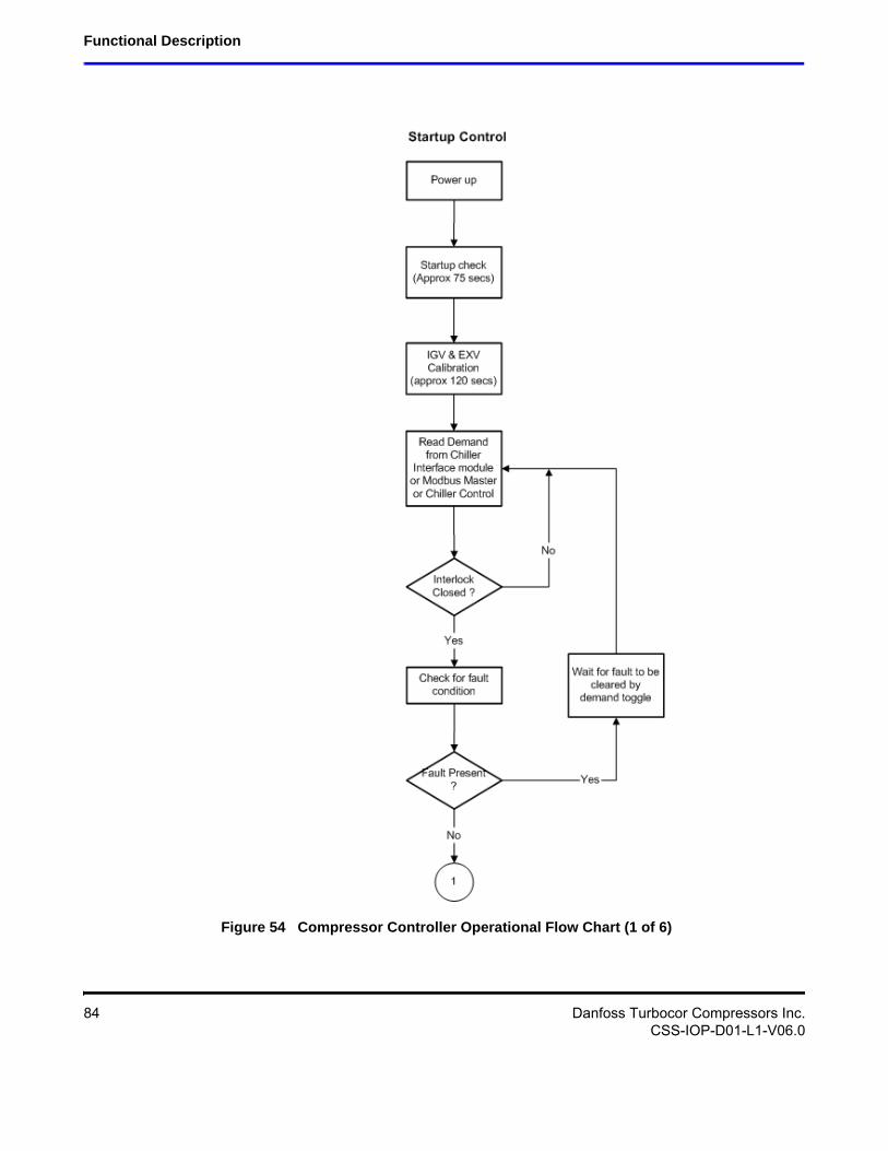
Functional Description
Figure 54 Compressor Controller Operational Flow Chart (1 of 6)
84 Danfoss Turbocor Compressors Inc.CSS-IOP-D01-L1-V06.0

Installation and Operation Manual
Figure 55 Compressor Controller Operational Flow Chart (2 of 6)
Danfoss Turbocor Compressors Inc. 85CSS-IOP-D01-L1-V06.0
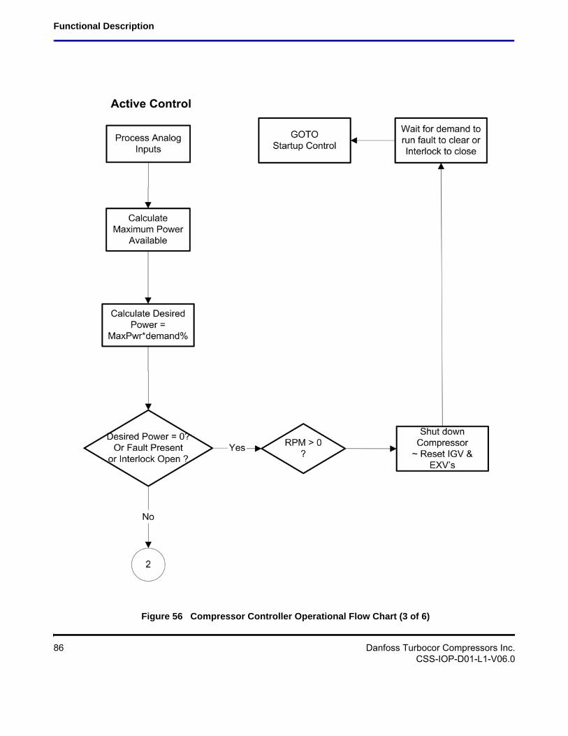
Functional Description
Figure 56 Compressor Controller Operational Flow Chart (3 of 6)
86 Danfoss Turbocor Compressors Inc.CSS-IOP-D01-L1-V06.0
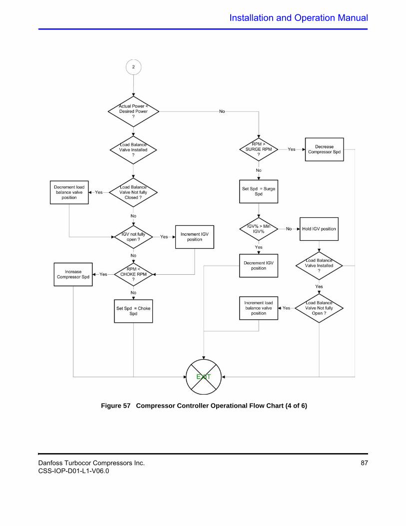
Installation and Operation Manual
Figure 57 Compressor Controller Operational Flow Chart (4 of 6)
Danfoss Turbocor Compressors Inc. 87CSS-IOP-D01-L1-V06.0
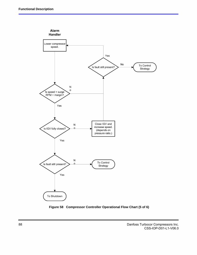
Functional Description
Figure 58 Compressor Controller Operational Flow Chart (5 of 6)
88 Danfoss Turbocor Compressors Inc.CSS-IOP-D01-L1-V06.0
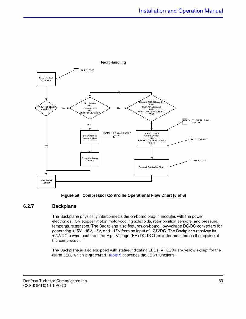
Installation and Operation Manual
Check for fault condition
FAULT_CODEnot equal to 0
Start Active Control
Fault PresentAND
demand = 0%AND
Shaft Not Levitated?
Demand NOT EQUAL 0%AND
Shaft Not LevitatedAND
READY_TO_CLEAR_FLAG =TRUE
Set System to Ready to Clear
Reset the Status Contacts
Yes
Yes
No
Clear CC faultClear BMC fault
SetREADY_TO_CLEAR_FLAG =
False
Recheck Fault After Clear
No
READY_TO_CLEAR_FLAG = TRUE
READY_TO_CLEAR_FLAG = FALSE
FAULT_CODE = 0
FAULT_CODE
Fault Handling
FAULT_CODE
No
Figure 59 Compressor Controller Operational Flow Chart (6 of 6)
6.2.7 Backplane
The Backplane physically interconnects the on-board plug-in modules with the power electronics, IGV stepper motor, motor-cooling solenoids, rotor position sensors, and pressure/temperature sensors. The Backplane also features on-board, low-voltage DC-DC converters for generating +15V, -15V, +5V, and +17V from an input of +24VDC. The Backplane receives its +24VDC power input from the High-Voltage (HV) DC-DC Converter mounted on the topside of the compressor.
The Backplane is also equipped with status-indicating LEDs. All LEDs are yellow except for the alarm LED, which is green/red. Table 9 describes the LEDs functions.
Danfoss Turbocor Compressors Inc. 89CSS-IOP-D01-L1-V06.0
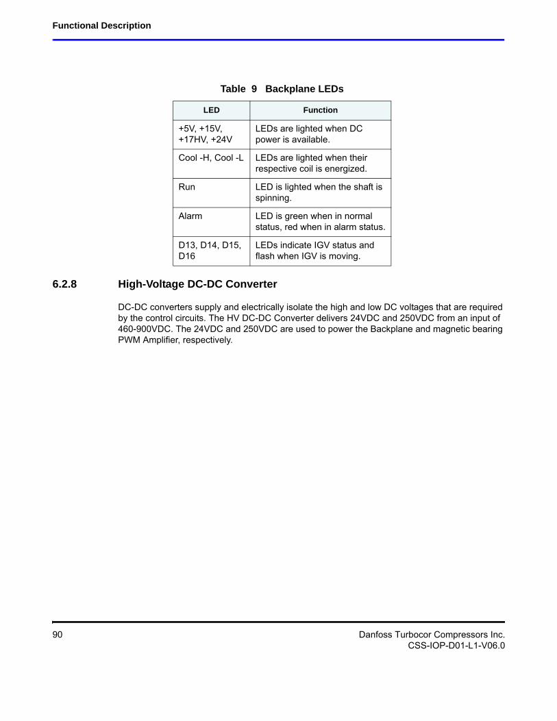
Functional Description
Table 9 Backplane LEDs
LED Function
+5V, +15V, +17HV, +24V
LEDs are lighted when DC power is available.
Cool -H, Cool -L LEDs are lighted when their respective coil is energized.
Run LED is lighted when the shaft is spinning.
Alarm LED is green when in normal status, red when in alarm status.
D13, D14, D15, D16
LEDs indicate IGV status and flash when IGV is moving.
6.2.8 High-Voltage DC-DC Converter
DC-DC converters supply and electrically isolate the high and low DC voltages that are required by the control circuits. The HV DC-DC Converter delivers 24VDC and 250VDC from an input of 460-900VDC. The 24VDC and 250VDC are used to power the Backplane and magnetic bearing PWM Amplifier, respectively.
90 Danfoss Turbocor Compressors Inc.CSS-IOP-D01-L1-V06.0
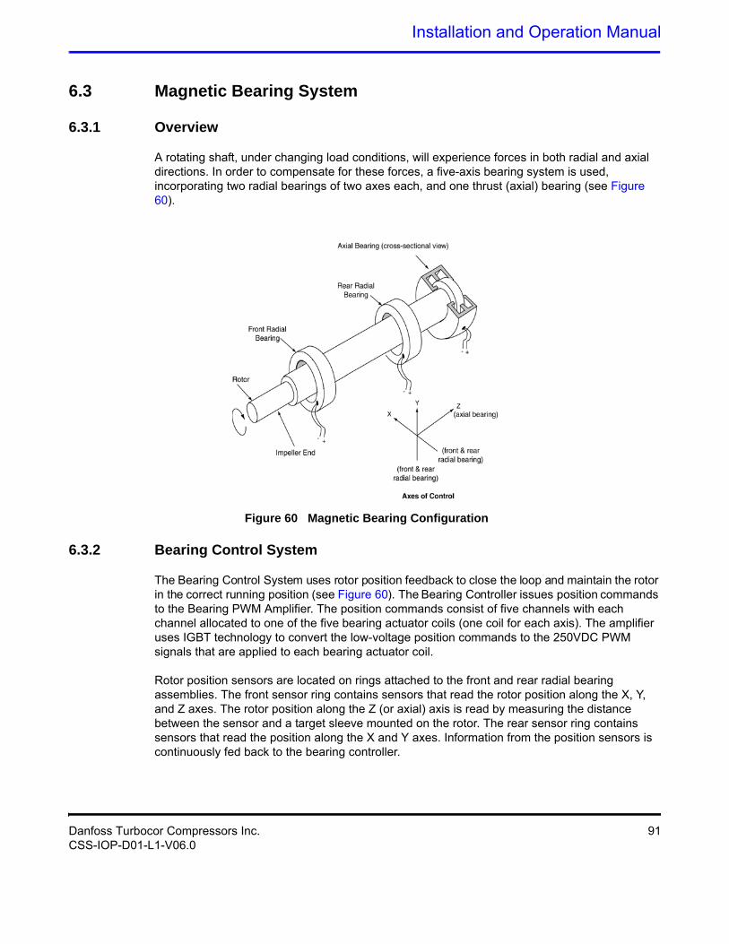
Installation and Operation Manual
6.3 Magnetic Bearing System
6.3.1 Overview
A rotating shaft, under changing load conditions, will experience forces in both radial and axial directions. In order to compensate for these forces, a five-axis bearing system is used, incorporating two radial bearings of two axes each, and one thrust (axial) bearing (see Figure 60).
Figure 60 Magnetic Bearing Configuration
6.3.2 Bearing Control System
The Bearing Control System uses rotor position feedback to close the loop and maintain the rotor in the correct running position (see Figure 60). The Bearing Controller issues position commands to the Bearing PWM Amplifier. The position commands consist of five channels with each channel allocated to one of the five bearing actuator coils (one coil for each axis). The amplifier uses IGBT technology to convert the low-voltage position commands to the 250VDC PWM signals that are applied to each bearing actuator coil.
Rotor position sensors are located on rings attached to the front and rear radial bearing assemblies. The front sensor ring contains sensors that read the rotor position along the X, Y, and Z axes. The rotor position along the Z (or axial) axis is read by measuring the distance between the sensor and a target sleeve mounted on the rotor. The rear sensor ring contains sensors that read the position along the X and Y axes. Information from the position sensors is continuously fed back to the bearing controller.
Danfoss Turbocor Compressors Inc. 91CSS-IOP-D01-L1-V06.0
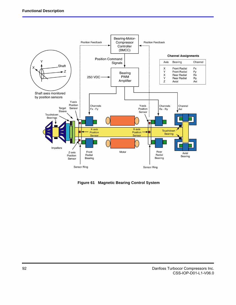
Functional Description
Figure 61 Magnetic Bearing Control System
92 Danfoss Turbocor Compressors Inc.CSS-IOP-D01-L1-V06.0
Installation and Operation Manual
6.4 Power Line Control and Filtering
6.4.1 Power Line Contactor
Consult local codes to determine if a power line contactor is necessary for your application.
NOTEIt is not recommended to use the contactor to start/stop the compressor during normal operation. compressor generator mode is used for emergency purposes only.
6.4.2 Power Line Filters and Line Reactor
The equipment described in this section may be available from Danfoss Turbocor as compressor accessories. For equipment specifications, see the Applications Manual.
6.4.2.1 EMI Filter
The EMI filter minimizes harmonics in the higher-frequency domain (typically above 1kHz). It should be located between the contactor and the line reactor. The European version of an EMI filter is required for CE compliance.
6.4.2.2 Line Reactor
The line reactor acts as an input buffer between the motor drive power circuits and the AC line power. Line reactors provide additional circuit impedance that improves power factor, reduces line current harmonics, and dampens the transient voltages on the power line.
6.4.2.3 Harmonic Filter
The harmonic filter operates in conjunction with the line reactor to minimize low-frequency harmonics on the power line emanating from the switching devices on the compressor. It should be located between the line reactor and the compressor.
Danfoss Turbocor Compressors Inc. 93CSS-IOP-D01-L1-V06.0
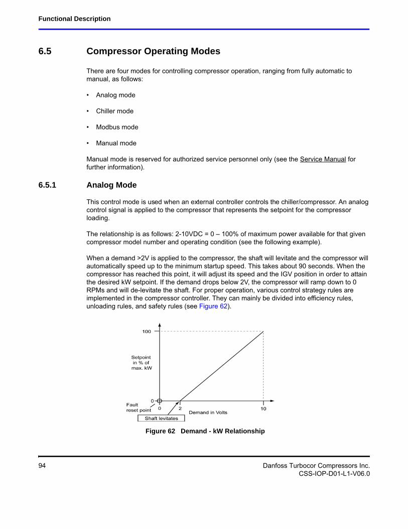
Functional Description
6.5 Compressor Operating Modes
There are four modes for controlling compressor operation, ranging from fully automatic to manual, as follows:
• Analog mode
• Chiller mode
• Modbus mode
• Manual mode
Manual mode is reserved for authorized service personnel only (see the Service Manual for further information).
6.5.1 Analog Mode
This control mode is used when an external controller controls the chiller/compressor. An analog control signal is applied to the compressor that represents the setpoint for the compressor loading.
The relationship is as follows: 2-10VDC = 0 – 100% of maximum power available for that given compressor model number and operating condition (see the following example).
When a demand >2V is applied to the compressor, the shaft will levitate and the compressor will automatically speed up to the minimum startup speed. This takes about 90 seconds. When the compressor has reached this point, it will adjust its speed and the IGV position in order to attain the desired kW setpoint. If the demand drops below 2V, the compressor will ramp down to 0 RPMs and will de-levitate the shaft. For proper operation, various control strategy rules are implemented in the compressor controller. They can mainly be divided into efficiency rules, unloading rules, and safety rules (see Figure 62).
Figure 62 Demand - kW Relationship
94 Danfoss Turbocor Compressors Inc.CSS-IOP-D01-L1-V06.0
Installation and Operation Manual
6.5.2 Chiller Mode
When a chiller is equipped with a single compressor, a separate chiller controller is not needed; the compressor can be set to control the leaving/entering chilled water temperature by connecting an NTC temperature sensor to the I/O Board (refer to the Application Manual for sensor characteristics). The chilled water setpoint can be set through the Service Monitoring Tool.
6.5.3 Modbus Mode
The demand to the compressor motor kW can be either directly set using the Service Monitoring Tool or can be provided by the chiller controller via the Modbus over an RS-485 link. The compressor will adjust its speed in order to attain the desired setpoint. The compressor controller will keep monitoring all critical parameters and ensure safe operation.
6.6 Expansion Valve Control
The compressor has the optional functionality to control two electronic expansion valves. These valves should be of the stepper motor design (see the Applications Manual for details on which valves can be used). The first expansion valve (or main expansion valve) can be set up to control liquid level, superheat, or load balancing (hot gas by-pass valve). When controlling liquid level, it will normally control the level in the evaporator or condenser. The second valve (or auxiliary expansion valve) can also be set up to control liquid level, superheat, or load balancing. When controlling liquid level, it will normally be for economizer level control.
Danfoss Turbocor Compressors Inc. 95CSS-IOP-D01-L1-V06.0
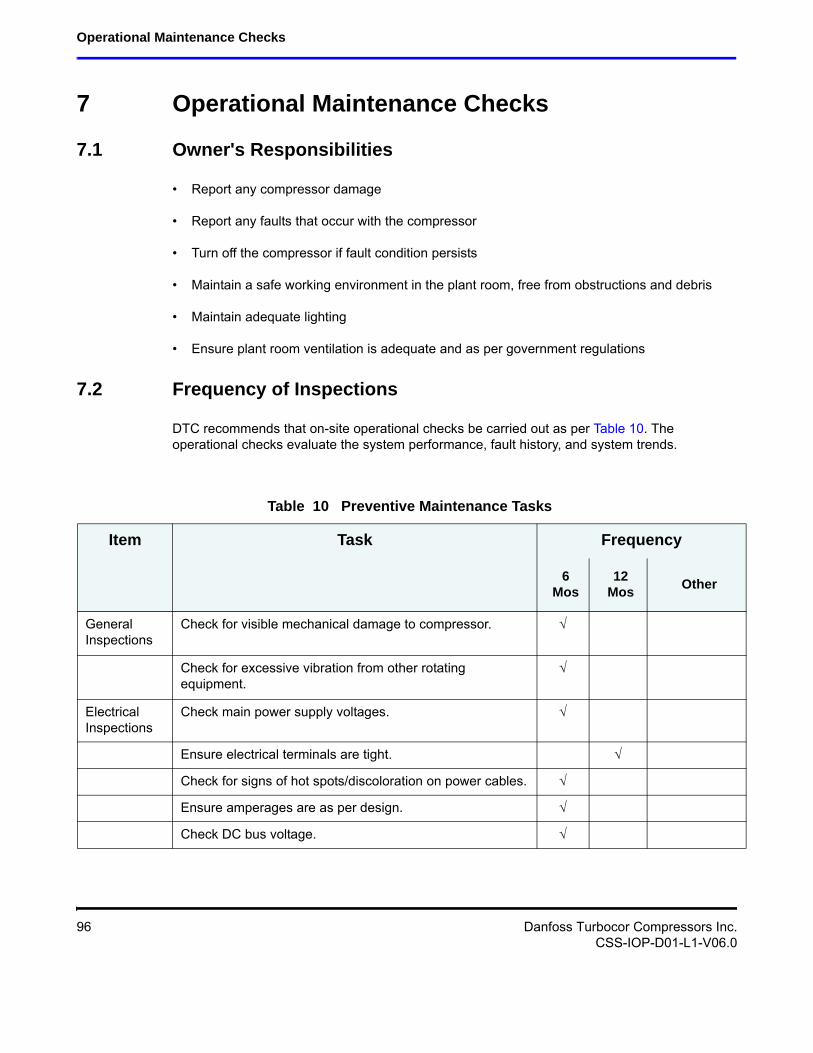
Operational Maintenance Checks
7 Operational Maintenance Checks
7.1 Owner's Responsibilities
• Report any compressor damage
• Report any faults that occur with the compressor
• Turn off the compressor if fault condition persists
• Maintain a safe working environment in the plant room, free from obstructions and debris
• Maintain adequate lighting
• Ensure plant room ventilation is adequate and as per government regulations
7.2 Frequency of Inspections
DTC recommends that on-site operational checks be carried out as per Table 10. The operational checks evaluate the system performance, fault history, and system trends.
Table 10 Preventive Maintenance Tasks
Item Task Frequency
6 Mos
12 Mos
Other
General Inspections
Check for visible mechanical damage to compressor.
Check for excessive vibration from other rotating equipment.
Electrical Inspections
Check main power supply voltages.
Ensure electrical terminals are tight.
Check for signs of hot spots/discoloration on power cables.
Ensure amperages are as per design.
Check DC bus voltage.
96 Danfoss Turbocor Compressors Inc.CSS-IOP-D01-L1-V06.0
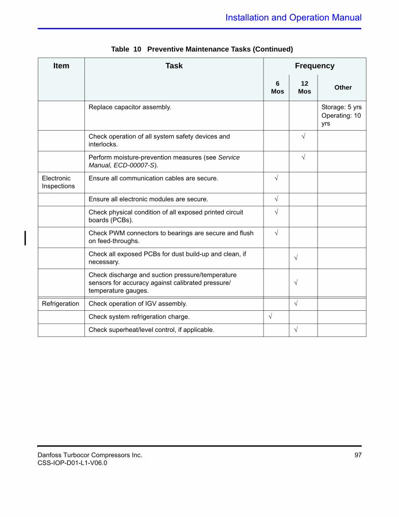
Installation and Operation Manual
Replace capacitor assembly. Storage: 5 yrsOperating: 10 yrs
Check operation of all system safety devices and interlocks.
Perform moisture-prevention measures (see Service Manual, ECD-00007-S).
Electronic Inspections
Ensure all communication cables are secure.
Ensure all electronic modules are secure.
Check physical condition of all exposed printed circuit boards (PCBs).
Check PWM connectors to bearings are secure and flush on feed-throughs.
Check all exposed PCBs for dust build-up and clean, if necessary.
Check discharge and suction pressure/temperature sensors for accuracy against calibrated pressure/temperature gauges.
Refrigeration Check operation of IGV assembly.
Check system refrigeration charge.
Check superheat/level control, if applicable.
Table 10 Preventive Maintenance Tasks (Continued)
Item Task Frequency
6 Mos
12 Mos
Other
Danfoss Turbocor Compressors Inc. 97CSS-IOP-D01-L1-V06.0
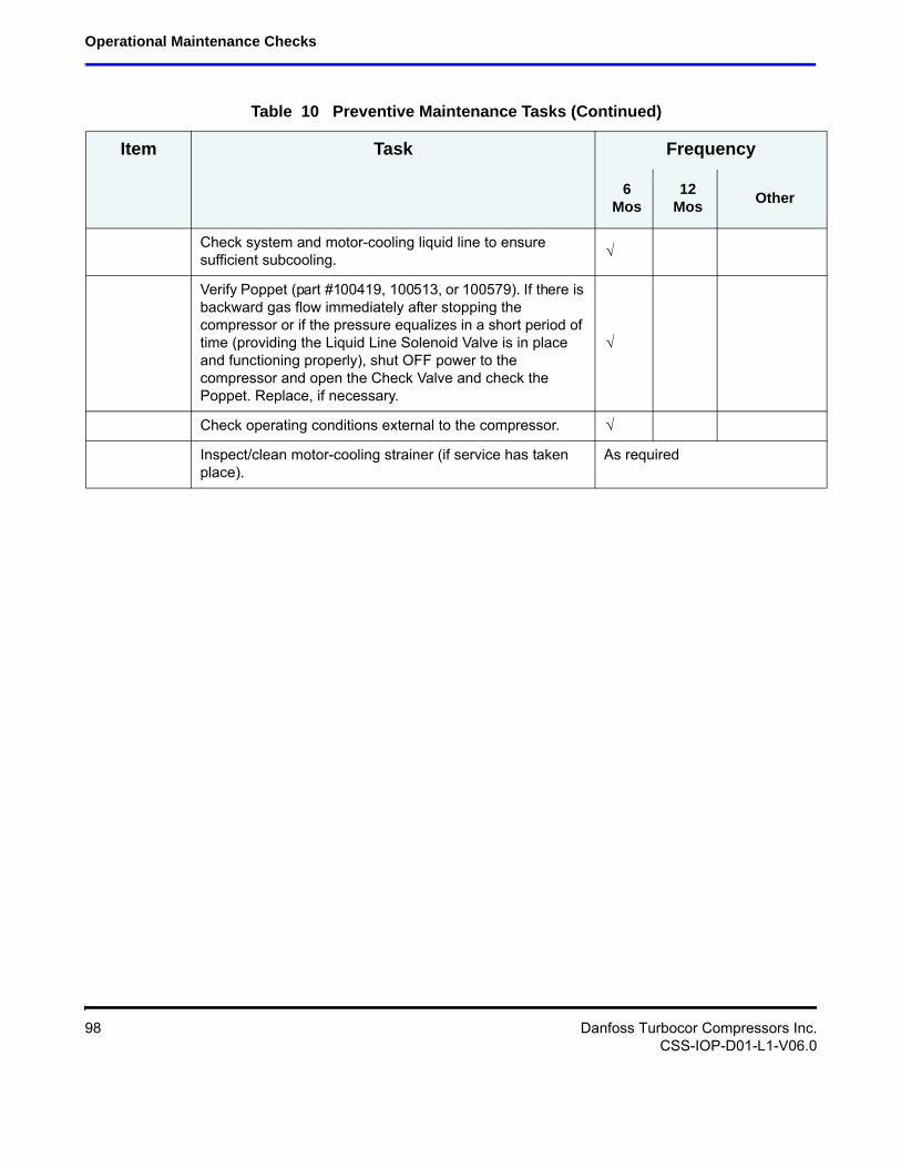
Operational Maintenance Checks
Check system and motor-cooling liquid line to ensure sufficient subcooling.
Verify Poppet (part #100419, 100513, or 100579). If there is backward gas flow immediately after stopping the compressor or if the pressure equalizes in a short period of time (providing the Liquid Line Solenoid Valve is in place and functioning properly), shut OFF power to the compressor and open the Check Valve and check the Poppet. Replace, if necessary.
Check operating conditions external to the compressor.
Inspect/clean motor-cooling strainer (if service has taken place).
As required
Table 10 Preventive Maintenance Tasks (Continued)
Item Task Frequency
6 Mos
12 Mos
Other
98 Danfoss Turbocor Compressors Inc.CSS-IOP-D01-L1-V06.0
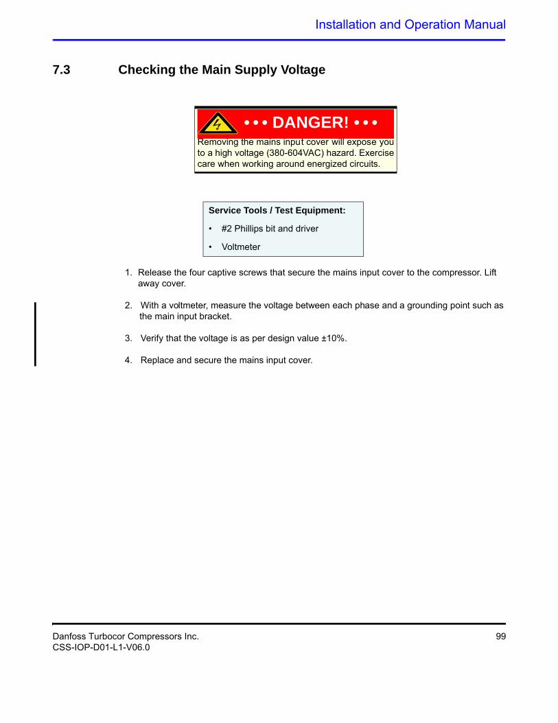
Installation and Operation Manual
7.3 Checking the Main Supply Voltage
Removing the mains input cover will expose you to a high voltage (380-604VAC) hazard. Exercise care when working around energized circuits.
Service Tools / Test Equipment:
1. Release the four captive screws that secure the mains input cover to the compressor. Lift away cover.
2. With a voltmeter, measure the voltage between each phase and a grounding point such as the main input bracket.
3. Verify that the voltage is as per design value ±10%.
4. Replace and secure the mains input cover.
• • • DANGER! • • •
• #2 Phillips bit and driver
• Voltmeter
Danfoss Turbocor Compressors Inc. 99CSS-IOP-D01-L1-V06.0

This Page Left Intentionally Blank
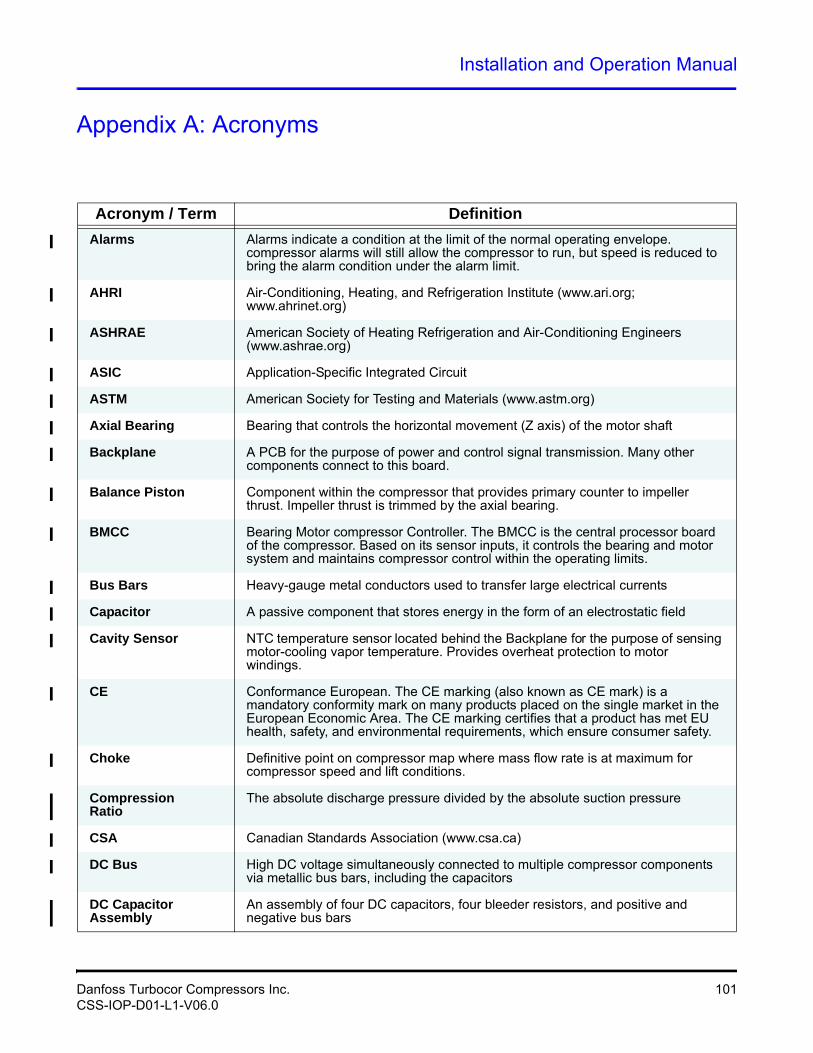
Installation and Operation Manual
Appendix A: Acronyms
Acronym / Term Definition
Alarms Alarms indicate a condition at the limit of the normal operating envelope. compressor alarms will still allow the compressor to run, but speed is reduced to bring the alarm condition under the alarm limit.
AHRI Air-Conditioning, Heating, and Refrigeration Institute (www.ari.org; www.ahrinet.org)
ASHRAE American Society of Heating Refrigeration and Air-Conditioning Engineers (www.ashrae.org)
ASIC Application-Specific Integrated Circuit
ASTM American Society for Testing and Materials (www.astm.org)
Axial Bearing Bearing that controls the horizontal movement (Z axis) of the motor shaft
Backplane A PCB for the purpose of power and control signal transmission. Many other components connect to this board.
Balance Piston Component within the compressor that provides primary counter to impeller thrust. Impeller thrust is trimmed by the axial bearing.
BMCC Bearing Motor compressor Controller. The BMCC is the central processor board of the compressor. Based on its sensor inputs, it controls the bearing and motor system and maintains compressor control within the operating limits.
Bus Bars Heavy-gauge metal conductors used to transfer large electrical currents
Capacitor A passive component that stores energy in the form of an electrostatic field
Cavity Sensor NTC temperature sensor located behind the Backplane for the purpose of sensing motor-cooling vapor temperature. Provides overheat protection to motor windings.
CE Conformance European. The CE marking (also known as CE mark) is a mandatory conformity mark on many products placed on the single market in the European Economic Area. The CE marking certifies that a product has met EU health, safety, and environmental requirements, which ensure consumer safety.
Choke Definitive point on compressor map where mass flow rate is at maximum for compressor speed and lift conditions.
CompressionRatio
The absolute discharge pressure divided by the absolute suction pressure
CSA Canadian Standards Association (www.csa.ca)
DC Bus High DC voltage simultaneously connected to multiple compressor components via metallic bus bars, including the capacitors
DC Capacitor Assembly
An assembly of four DC capacitors, four bleeder resistors, and positive and negative bus bars
Danfoss Turbocor Compressors Inc. 101CSS-IOP-D01-L1-V06.0
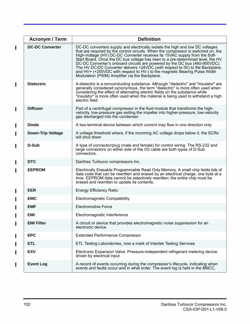
DC-DC Converter DC-DC converters supply and electrically isolate the high and low DC voltages that are required by the control circuits. When the compressor is switched on, the High-Voltage (HV) DC-DC Converter receives its 15VAC supply from the Soft-Start Board. Once the DC bus voltage has risen to a pre-determined level, the HV DC-DC Converter’s onboard circuits are powered by the DC bus (460-900VDC). The HV DC-DC Converter delivers +24VDC (with respect to 0V) to the Backplane, and HV+ (+250VDC with respect to HV-) to the magnetic Bearing Pulse Width Modulation (PWM) Amplifier via the Backplane.
Dielectric A dielectric is a nonconducting substance. Although "dielectric" and "insulator" are generally considered synonymous, the term "dielectric" is more often used when considering the effect of alternating electric fields on the substance while "insulator" is more often used when the material is being used to withstand a high electric field.
Diffuser Part of a centrifugal compressor in the fluid module that transforms the high-velocity, low-pressure gas exiting the impeller into higher-pressure, low-velocity gas discharged into the condenser.
Diode A two-terminal device between which current may flow in one direction only
Down-Trip Voltage A voltage threshold where, if the incoming AC voltage drops below it, the SCRs will shut down
D-Sub A type of connector/plug (male and female) for control wiring. The RS-232 and large connectors on either side of the I/O cable are both types of D-Sub connectors.
DTC Danfoss Turbocor compressors Inc.
EEPROM Electrically Erasable Programmable Read Only Memory. A small chip holds bits of data code that can be rewritten and erased by an electrical charge, one byte at a time. EEPROM data cannot be selectively rewritten; the entire chip must be erased and rewritten to update its contents.
EER Energy Efficiency Ratio
EMC Electromagnetic Compatibility
EMF Electromotive Force
EMI Electromagnetic Interference
EMI Filter A circuit or device that provides electromagnetic noise suppression for an electronic device
EPC Extended Performance Compressor
ETL ETL Testing Laboratories, now a mark of Intertek Testing Services
EXV Electronic Expansion Valve. Pressure-independent refrigerant metering device driven by electrical input
Event Log A record of events occurring during the compressor’s lifecycle, indicating when events and faults occur and in what order. The event log is held in the BMCC.
Acronym / Term Definition
102 Danfoss Turbocor Compressors Inc.CSS-IOP-D01-L1-V06.0
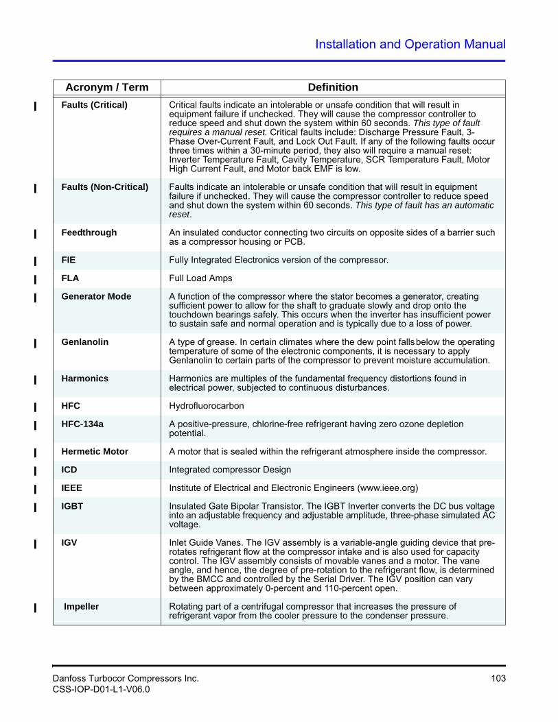
Installation and Operation Manual
Faults (Critical) Critical faults indicate an intolerable or unsafe condition that will result in equipment failure if unchecked. They will cause the compressor controller to reduce speed and shut down the system within 60 seconds. This type of fault requires a manual reset. Critical faults include: Discharge Pressure Fault, 3-Phase Over-Current Fault, and Lock Out Fault. If any of the following faults occur three times within a 30-minute period, they also will require a manual reset: Inverter Temperature Fault, Cavity Temperature, SCR Temperature Fault, Motor High Current Fault, and Motor back EMF is low.
Faults (Non-Critical) Faults indicate an intolerable or unsafe condition that will result in equipment failure if unchecked. They will cause the compressor controller to reduce speed and shut down the system within 60 seconds. This type of fault has an automatic reset.
Feedthrough An insulated conductor connecting two circuits on opposite sides of a barrier such as a compressor housing or PCB.
FIE Fully Integrated Electronics version of the compressor.
FLA Full Load Amps
Generator Mode A function of the compressor where the stator becomes a generator, creating sufficient power to allow for the shaft to graduate slowly and drop onto the touchdown bearings safely. This occurs when the inverter has insufficient power to sustain safe and normal operation and is typically due to a loss of power.
Genlanolin A type of grease. In certain climates where the dew point falls below the operating temperature of some of the electronic components, it is necessary to apply Genlanolin to certain parts of the compressor to prevent moisture accumulation.
Harmonics Harmonics are multiples of the fundamental frequency distortions found in electrical power, subjected to continuous disturbances.
HFC Hydrofluorocarbon
HFC-134a A positive-pressure, chlorine-free refrigerant having zero ozone depletion potential.
Hermetic Motor A motor that is sealed within the refrigerant atmosphere inside the compressor.
ICD Integrated compressor Design
IEEE Institute of Electrical and Electronic Engineers (www.ieee.org)
IGBT Insulated Gate Bipolar Transistor. The IGBT Inverter converts the DC bus voltage into an adjustable frequency and adjustable amplitude, three-phase simulated AC voltage.
IGV Inlet Guide Vanes. The IGV assembly is a variable-angle guiding device that pre-rotates refrigerant flow at the compressor intake and is also used for capacity control. The IGV assembly consists of movable vanes and a motor. The vane angle, and hence, the degree of pre-rotation to the refrigerant flow, is determined by the BMCC and controlled by the Serial Driver. The IGV position can vary between approximately 0-percent and 110-percent open.
Impeller Rotating part of a centrifugal compressor that increases the pressure of refrigerant vapor from the cooler pressure to the condenser pressure.
Acronym / Term Definition
Danfoss Turbocor Compressors Inc. 103CSS-IOP-D01-L1-V06.0
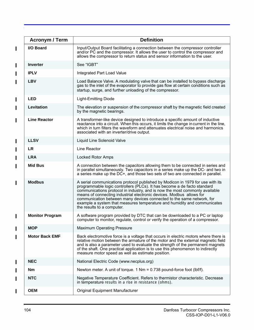
I/O Board Input/Output Board facilitating a connection between the compressor controller and/or PC and the compressor. It allows the user to control the compressor and allows the compressor to return status and sensor information to the user.
Inverter See “IGBT”
IPLV Integrated Part Load Value
LBV Load Balance Valve. A modulating valve that can be installed to bypass discharge gas to the inlet of the evaporator to provide gas flow at certain conditions such as startup, surge, and further unloading of the compressor.
LED Light-Emitting Diode
Levitation The elevation or suspension of the compressor shaft by the magnetic field created by the magnetic bearings.
Line Reactor A transformer-like device designed to introduce a specific amount of inductive reactance into a circuit. When this occurs, it limits the change in current in the line, which in turn filters the waveform and attenuates electrical noise and harmonics associated with an inverter/drive output.
LLSV Liquid Line Solenoid Valve
LR Line Reactor
LRA Locked Rotor Amps
Mid Bus A connection between the capacitors allowing them to be connected in series and in parallel simultaneously. Two capacitors in a series make up the DC- and two in a series make up the DC+, and those two sets of two are connected in parallel.
Modbus A serial communications protocol published by Modicon in 1979 for use with its programmable logic controllers (PLCs). It has become a de facto standard communications protocol in industry, and is now the most commonly available means of connecting industrial electronic devices. Modbus allows for communication between many devices connected to the same network, for example a system that measures temperature and humidity and communicates the results to a computer.
Monitor Program A software program provided by DTC that can be downloaded to a PC or laptop computer to monitor, regulate, control or verify the operation of a compressor.
MOP Maximum Operating Pressure
Motor Back EMF Back electromotive force is a voltage that occurs in electric motors where there is relative motion between the armature of the motor and the external magnetic field and is also a parameter used to evaluate the strength of the permanent magnets of the shaft. One practical application is to use this phenomenon to indirectly measure motor speed as well as estimate position.
NEC National Electric Code (www.necplus.org)
Nm Newton meter. A unit of torque. 1 Nm = 0.738 pound-force foot (lbf/f).
NTC Negative Temperature Coefficient. Refers to thermistor characteristic. Decrease in temperature results in a rise in resistance (ohms).
OEM Original Equipment Manufacturer
Acronym / Term Definition
104 Danfoss Turbocor Compressors Inc.CSS-IOP-D01-L1-V06.0
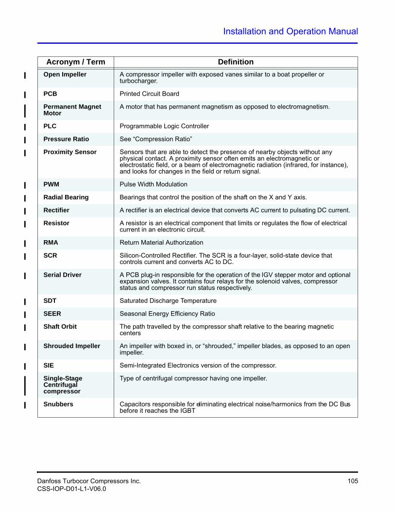
Installation and Operation Manual
Open Impeller A compressor impeller with exposed vanes similar to a boat propeller or turbocharger.
PCB Printed Circuit Board
Permanent Magnet Motor
A motor that has permanent magnetism as opposed to electromagnetism.
PLC Programmable Logic Controller
Pressure Ratio See “Compression Ratio”
Proximity Sensor Sensors that are able to detect the presence of nearby objects without any physical contact. A proximity sensor often emits an electromagnetic or electrostatic field, or a beam of electromagnetic radiation (infrared, for instance), and looks for changes in the field or return signal.
PWM Pulse Width Modulation
Radial Bearing Bearings that control the position of the shaft on the X and Y axis.
Rectifier A rectifier is an electrical device that converts AC current to pulsating DC current.
Resistor A resistor is an electrical component that limits or regulates the flow of electrical current in an electronic circuit.
RMA Return Material Authorization
SCR Silicon-Controlled Rectifier. The SCR is a four-layer, solid-state device that controls current and converts AC to DC.
Serial Driver A PCB plug-in responsible for the operation of the IGV stepper motor and optional expansion valves. It contains four relays for the solenoid valves, compressor status and compressor run status respectively.
SDT Saturated Discharge Temperature
SEER Seasonal Energy Efficiency Ratio
Shaft Orbit The path travelled by the compressor shaft relative to the bearing magnetic centers
Shrouded Impeller An impeller with boxed in, or “shrouded,” impeller blades, as opposed to an open impeller.
SIE Semi-Integrated Electronics version of the compressor.
Single-Stage Centrifugal compressor
Type of centrifugal compressor having one impeller.
Snubbers Capacitors responsible for eliminating electrical noise/harmonics from the DC Bus before it reaches the IGBT
Acronym / Term Definition
Danfoss Turbocor Compressors Inc. 105CSS-IOP-D01-L1-V06.0
* Danfoss Turbocor’s commitment to excellence ensures continuous product improvements.
* Subject to change without notice.
Soft-Start Board / Soft-Starter
The Soft-Start Board limits in-rush current by progressively increasing the conduction angle of the SCRs. This technique is used at compressor startup while the DC capacitors are charging up. The Soft-Start Board takes as input a 3-phase voltage source at 50/60Hz from the input terminal and a DC voltage signal from the SCR output. In turn, it outputs pulses to the SCR and provides power to the High-Voltage (HV) DC-DC Converter. All voltages from the Soft-Start Board are with respect to the positive DC bus and not the compressor ground.
SST Saturated Suction Temperature
Surge The condition at which the compressor cannot sustain the discharge pressure, allowing refrigerant to temporarily and rapidly re-enter the compressor fluid path, creating a cavitating effect. This is an undesirable situation that should be avoided.
Thrust Bearing A bearing that absorbs the axial forces produced in a centrifugal compressor by the refrigerant pressure differential across the impeller.
Ton The basic unit for measuring the rate of heat transfer (12,000 BTU/H; 3.516 kw/H)
Touchdown Bearings
Carbon races or ball bearing for the purpose of preventing mechanical interference between the shaft and the magnetic bearings should they lose power or fail.
TT Twin Turbine
Two-Stage Centrifugal compressor
Type of centrifugal compressor having two impellers. The first-stage impeller raises the pressure of the refrigerant vapor approximately halfway from the cooler pressure to the condenser pressure, and the second-stage impeller raises the pressure the rest of the way. With a two-stage compressor, an interstage economizer may be used to improve the refrigeration cycle efficiency.
TXV Thermal Expansion Valve. A pressure-dependent refrigerant metering device that operates independently and is controlled by temperature.
UL Underwriters Laboratories (www.ul.com)
Up-Trip Voltage When the DC- bus reaches the up-trip voltage, the SCRs will be gated open continuously
VAC Volts Alternating Current
Vaned Diffuser An assembly of plates with curved vanes that serve to slow, compress, and reduce refrigerant rotation as it enters the second-stage impeller
Vaneless Diffuser Similar to a Vaned Diffuser, except that it does not possess any de-swirl vanes
VDC Volts Direct Current
VFD Variable Frequency Drive
Acronym / Term Definition
106 Danfoss Turbocor Compressors Inc.CSS-IOP-D01-L1-V06.0
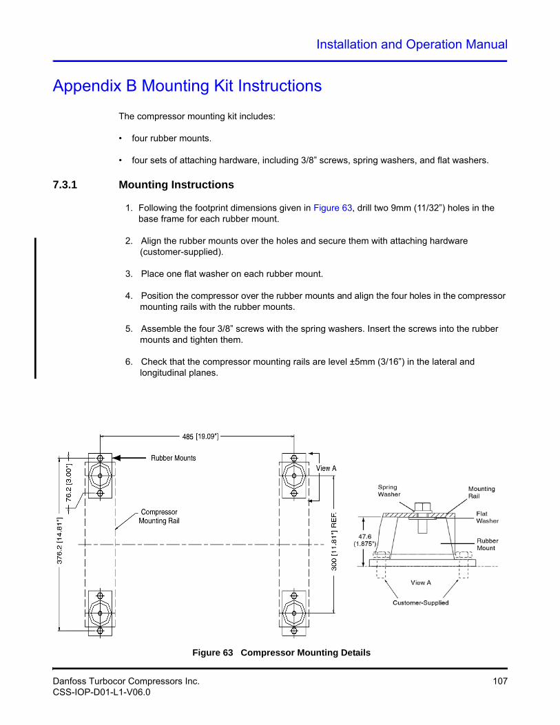
Installation and Operation Manual
Appendix B Mounting Kit Instructions
The compressor mounting kit includes:
• four rubber mounts.
• four sets of attaching hardware, including 3/8” screws, spring washers, and flat washers.
7.3.1 Mounting Instructions
1. Following the footprint dimensions given in Figure 63, drill two 9mm (11/32”) holes in the base frame for each rubber mount.
2. Align the rubber mounts over the holes and secure them with attaching hardware (customer-supplied).
3. Place one flat washer on each rubber mount.
4. Position the compressor over the rubber mounts and align the four holes in the compressor mounting rails with the rubber mounts.
5. Assemble the four 3/8” screws with the spring washers. Insert the screws into the rubber mounts and tighten them.
6. Check that the compressor mounting rails are level ±5mm (3/16”) in the lateral and longitudinal planes.
Figure 63 Compressor Mounting Details
Danfoss Turbocor Compressors Inc. 107CSS-IOP-D01-L1-V06.0

This Page Left Intentionally Blank
Installation and Operation Manual
Appendix C: Power Line Accessories Installation
Line Reactor Installation Instructions
These instructions apply to the installation of the line reactor kit in a main supply panel. See the Applications Manual for product specifications.
7.3.2 AC Line Cable Connection (From External Disconnect)
Figure 65 shows a schematic of the main input circuit and connections to the line reactor. Use this schematic as a guide for choosing the location of the line reactor.
1. Feed the AC line cable through the opening in the side of the main supply panel.
2. Attach the AC line wires to the line reactor terminals as shown in Figure 66.
3. Attach the ground cable to the mounting block on the panel wall. Ensure there is good electrical/mechanical contact between the ground cable and the panel wall.
4. Secure the AC line cable to the main supply panel using approved methods (i.e. cable gland).
7.3.3 AC Line Cable Connection (to Compressor Terminal)
1. Feed the AC line cable through the opening in the side of the main supply panel.
2. Attach the AC line wires to the line reactor output terminals as shown in Figure 67.
3. If a harmonic filter is being installed, attach its AC line wires to the line reactor output terminals.
4. Attach the ground wire to the mounting block on the panel wall. Ensure there is good electrical/mechanical contact between the ground wire and the panel wall.
5. Secure the AC line cable to the main supply panel using approved methods (i.e. cable gland).
6. See Section 4.6 "Power Wiring" for instructions on completing the AC input connection to the compressor.
NOTEThe custo mer is resp onsible for supplying the mounting hardware for the line reactor.
Danfoss Turbocor Compressors Inc. 109CSS-IOP-D01-L1-V06.0
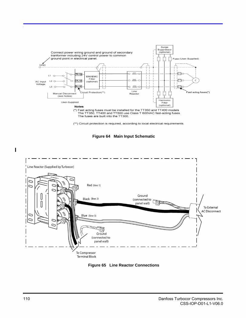
Figure 64 Main Input Schematic
Figure 65 Line Reactor Connections
110 Danfoss Turbocor Compressors Inc.CSS-IOP-D01-L1-V06.0
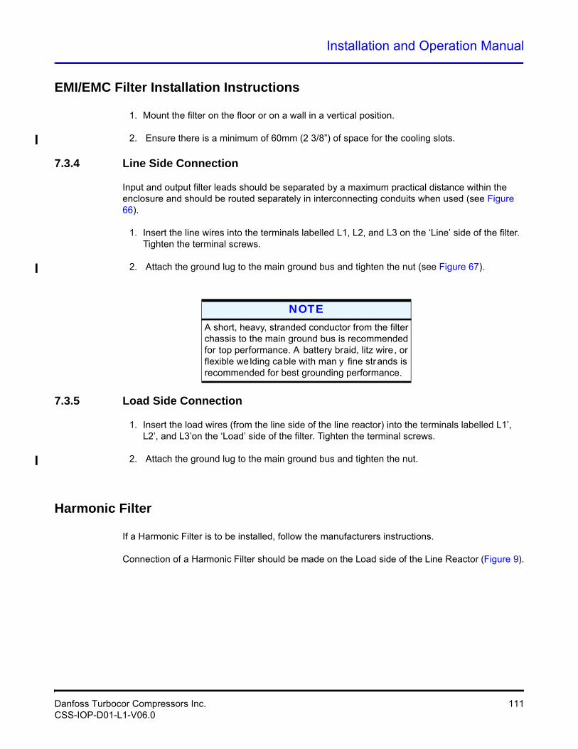
Installation and Operation Manual
EMI/EMC Filter Installation Instructions
1. Mount the filter on the floor or on a wall in a vertical position.
2. Ensure there is a minimum of 60mm (2 3/8”) of space for the cooling slots.
7.3.4 Line Side Connection
Input and output filter leads should be separated by a maximum practical distance within the enclosure and should be routed separately in interconnecting conduits when used (see Figure 66).
1. Insert the line wires into the terminals labelled L1, L2, and L3 on the ‘Line’ side of the filter. Tighten the terminal screws.
2. Attach the ground lug to the main ground bus and tighten the nut (see Figure 67).
7.3.5 Load Side Connection
1. Insert the load wires (from the line side of the line reactor) into the terminals labelled L1’, L2’, and L3’on the ‘Load’ side of the filter. Tighten the terminal screws.
2. Attach the ground lug to the main ground bus and tighten the nut.
Harmonic Filter
If a Harmonic Filter is to be installed, follow the manufacturers instructions.
Connection of a Harmonic Filter should be made on the Load side of the Line Reactor (Figure 9).
NOTEA short, heavy, stranded conductor from the filter chassis to the main ground bus is recommended for top performance. A battery braid, litz wire, or flexible we lding cable with man y fine strands is recommended for best grounding performance.
Danfoss Turbocor Compressors Inc. 111CSS-IOP-D01-L1-V06.0
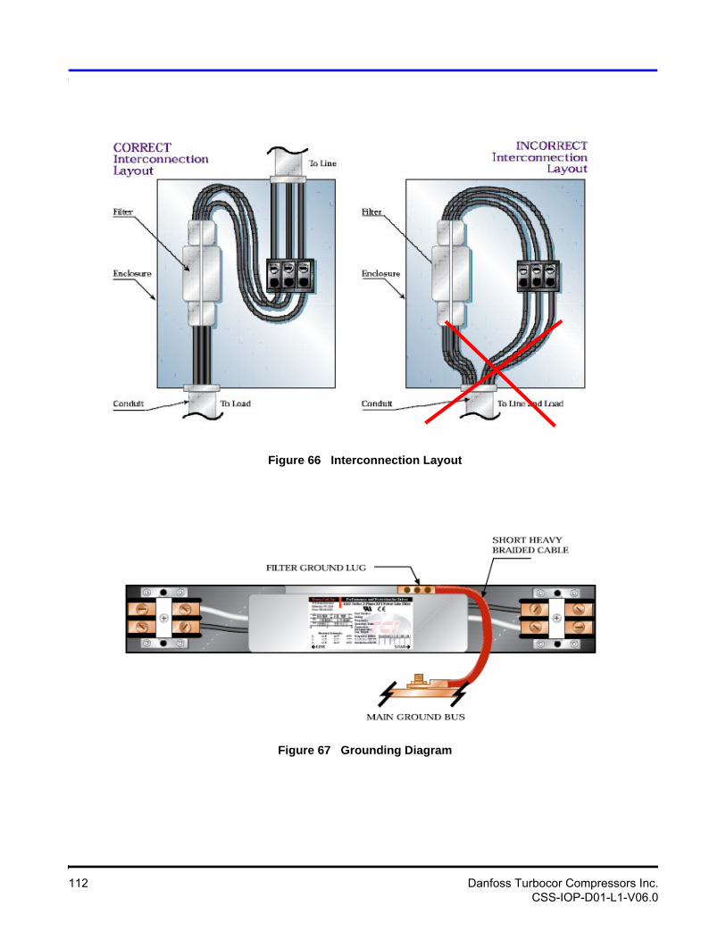
Figure 66 Interconnection Layout
Figure 67 Grounding Diagram
112 Danfoss Turbocor Compressors Inc.CSS-IOP-D01-L1-V06.0
Installation and Operation Manual
Appendix D: Valve / Flange Kit Installation Instructions
The instructions provided in this section apply to the following Turbocor valve/flange kits:
• Suction flange or service valve
• Discharge flange or service valve
• Economizer flange or service valve.
Each individual valve kit includes an O-ring, lubrication, and attaching hardware.
NOTEPlease consult Acce ssories M anual for p art numbers and availability.
! • • • CAUTION! • • •Brazing without the use o f dry nitrogen will result in debris being d eposited in the pipework, potentially causing blockage and/or damage.
! • • • CAUTION! • • •The heat generated from b razing can damage valve c omponents. Always us e in dustry standard practices to reduce valve temperature.
Danfoss Turbocor Compressors Inc. 113CSS-IOP-D01-L1-V06.0
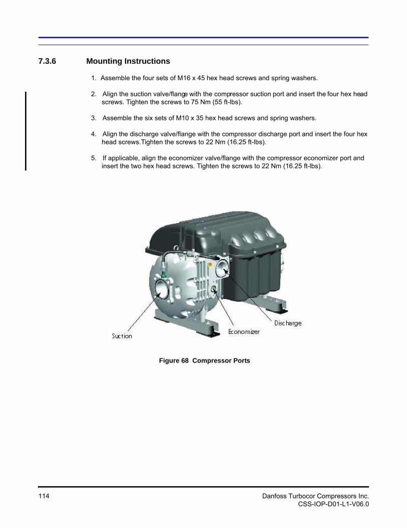
7.3.6 Mounting Instructions
1. Assemble the four sets of M16 x 45 hex head screws and spring washers.
2. Align the suction valve/flange with the compressor suction port and insert the four hex head screws. Tighten the screws to 75 Nm (55 ft-lbs).
3. Assemble the six sets of M10 x 35 hex head screws and spring washers.
4. Align the discharge valve/flange with the compressor discharge port and insert the four hex head screws.Tighten the screws to 22 Nm (16.25 ft-lbs).
5. If applicable, align the economizer valve/flange with the compressor economizer port and insert the two hex head screws. Tighten the screws to 22 Nm (16.25 ft-lbs).
Figure 68 Compressor Ports
114 Danfoss Turbocor Compressors Inc.CSS-IOP-D01-L1-V06.0
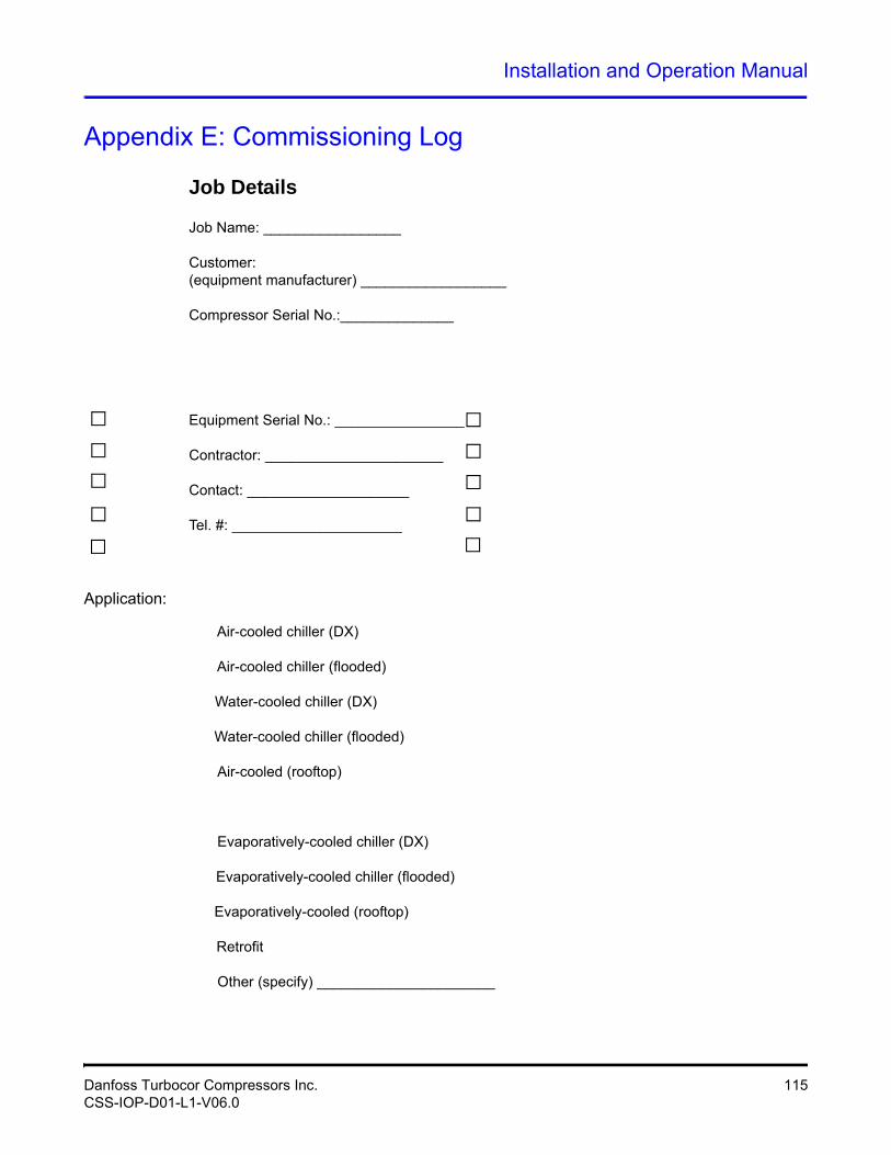
Installation and Operation Manual
Appendix E: Commissioning Log
Job Details
Job Name: _________________
Customer: (equipment manufacturer) __________________
Compressor Serial No.:______________
Equipment Serial No.: ________________
Contractor: ______________________
Contact: ____________________
Tel. #: _____________________
Application:
Air-cooled chiller (DX)
Air-cooled chiller (flooded)
Water-cooled chiller (DX)
Water-cooled chiller (flooded)
Air-cooled (rooftop)
Evaporatively-cooled chiller (DX)
Evaporatively-cooled chiller (flooded)
Evaporatively-cooled (rooftop)
Retrofit
Other (specify) ______________________
Danfoss Turbocor Compressors Inc. 115CSS-IOP-D01-L1-V06.0
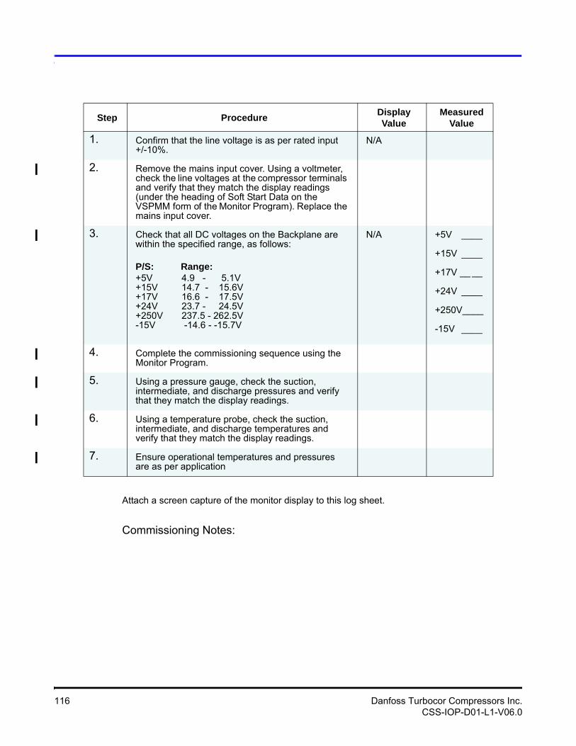
Attach a screen capture of the monitor display to this log sheet.
Commissioning Notes:
Step ProcedureDisplay Value
MeasuredValue
1. Confirm that the line voltage is as per rated input +/-10%.
N/A
2. Remove the mains input cover. Using a voltmeter, check the line voltages at the compressor terminals and verify that they match the display readings (under the heading of Soft Start Data on the VSPMM form of the Monitor Program). Replace the mains input cover.
3. Check that all DC voltages on the Backplane are within the specified range, as follows:
P/S: Range:+5V 4.9 - 5.1V+15V 14.7 - 15.6V+17V 16.6 - 17.5V+24V 23.7 - 24.5V+250V 237.5 - 262.5V-15V -14.6 - -15.7V
N/A +5V ____
+15V ____
+17V __ __
+24V ____
+250V____
-15V ____
4. Complete the commissioning sequence using the Monitor Program.
5. Using a pressure gauge, check the suction, intermediate, and discharge pressures and verify that they match the display readings.
6. Using a temperature probe, check the suction, intermediate, and discharge temperatures and verify that they match the display readings.
7. Ensure operational temperatures and pressures are as per application
116 Danfoss Turbocor Compressors Inc.CSS-IOP-D01-L1-V06.0
Installation and Operation Manual
Technician Name: _____________________
Company: _________________________
Date: _________________
Telephone No. ______________
Note:This commissioning report must be duly completed and returned to DTC for warranty pur-poses.
Danfoss Turbocor Compressors Inc. 117CSS-IOP-D01-L1-V06.0

This Page Left Intentionally Blank
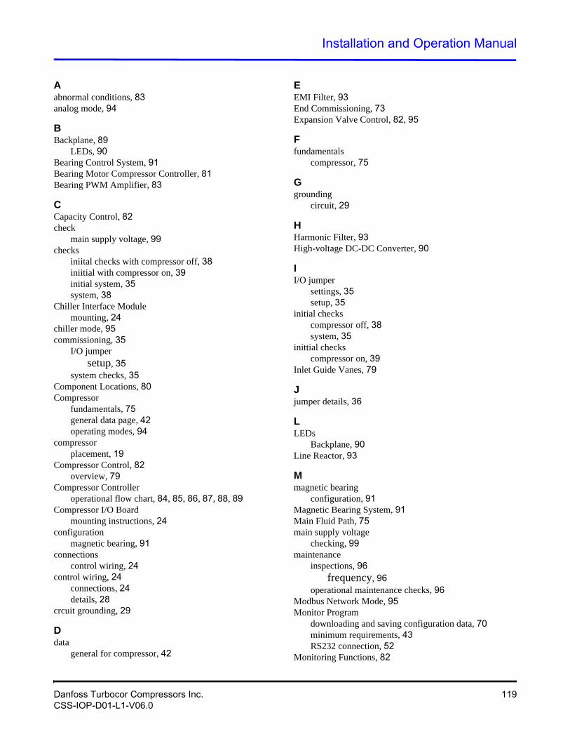
Installation and Operation Manual
Aabnormal conditions, 83analog mode, 94
BBackplane, 89
LEDs, 90Bearing Control System, 91Bearing Motor Compressor Controller, 81Bearing PWM Amplifier, 83
CCapacity Control, 82check
main supply voltage, 99checks
iniital checks with compressor off, 38iniitial with compressor on, 39initial system, 35system, 38
Chiller Interface Modulemounting, 24
chiller mode, 95commissioning, 35
I/O jumpersetup, 35
system checks, 35Component Locations, 80Compressor
fundamentals, 75general data page, 42operating modes, 94
compressorplacement, 19
Compressor Control, 82overview, 79
Compressor Controlleroperational flow chart, 84, 85, 86, 87, 88, 89
Compressor I/O Boardmounting instructions, 24
configurationmagnetic bearing, 91
connectionscontrol wiring, 24
control wiring, 24connections, 24details, 28
crcuit grounding, 29
Ddata
general for compressor, 42
EEMI Filter, 93End Commissioning, 73Expansion Valve Control, 82, 95
Ffundamentals
compressor, 75
Ggrounding
circuit, 29
HHarmonic Filter, 93High-voltage DC-DC Converter, 90
II/O jumper
settings, 35setup, 35
initial checkscompressor off, 38system, 35
inittial checkscompressor on, 39
Inlet Guide Vanes, 79
Jjumper details, 36
LLEDs
Backplane, 90Line Reactor, 93
Mmagnetic bearing
configuration, 91Magnetic Bearing System, 91Main Fluid Path, 75main supply voltage
checking, 99maintenance
inspections, 96frequency, 96
operational maintenance checks, 96Modbus Network Mode, 95Monitor Program
downloading and saving configuration data, 70minimum requirements, 43RS232 connection, 52
Monitoring Functions, 82
Danfoss Turbocor Compressors Inc. 119CSS-IOP-D01-L1-V06.0
Motor Cooling, 77Motor Drive System, 81Motor/Bearing Control, 82mounting instructions
Compressor I/O Board, 24
Ooperating modes
analog mode, 94chiller mode, 95compressor, 94Modbus network mode, 95
operational maintenance checks, 96owner’s responsibilities, 96
Ppiping connections, 21power line
contactor, 93control and filtering, 93filters, 93
power wiring, 33ground connection, 34
Rresponsibililities
owner’s, 96rigging requirements, 19
Ssafety precautions, 10safety summary, 10Serial Driver, 83settings
I/Ojumper, 35
system checks, 35, 38
Ttools, 9
service, 9TT300 Compressor Fluid Path, 76
Uunit placement, 19unpacking and inspection, 19
Vvoltage
checking main supply, 99
Wwiring
control, 24power, 33
120 Danfoss Turbocor Compressors Inc.CSS-IOP-D01-L1-V06.0


Copyright © 2010 Printed in USA
Danfoss Turbocor Compressors Inc., 1769 East Paul Dirac Drive, Tallahassee, Florida 32310Phone: 1-850-504-4800 Fax: 1-850-575-2126 www.turbocor.com
Top Related