


Languages
Pages
Legal


1
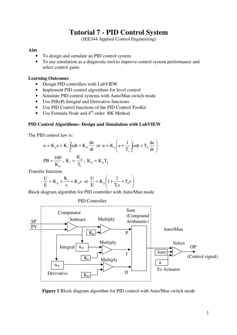
Tutorial 7 - PID Control System (JEE344 Applied Control Engineering)
Aim
• To design and simulate an PID control system
• To use simulation as a diagnostic tool to improve control system performance and
select control gains
Learning Outcomes
• Design PID controllers with LabVIEW
• Implement PID control algorithms for level control
• Simulate PID control systems with Auto/Man switch mode
• Use PtByPt Integral and Derivative functions
• Use PID Control functions of the PID Control Toolkit
• Use Formula Node and 4th
-order RK Method
PID Control Algorithms– Design and Simulation with LabVIEW
The PID control law is:
dt
deKedtKeKu d
t
0
ip ++= ∫ or
++= ∫ dt
deTedt
T
1eKu d
t
0i
p
pK
100PB = ;
i
p
iT
KK = ; dpd TKK =
Transfer function:
sKs
KK
E
Ud
ip ++= or
++= sT
sT
11K
E
Ud
i
p
Block diagram algorithm for PID controller with Auto/Man mode
Figure 1 Block diagram algorithm for PID control with Auto/Man switch mode
uin
Kp
SP
Integral
Subtract Multiply
Sum
(Compound
Arithmetic)
PV
Auto
4
Select
To Actuator
OP
(Control signal)
PID Controller
Auto/Man
KI
Multiply
KD
Multiply uin
Derivative
Comparator
P
I
D

2
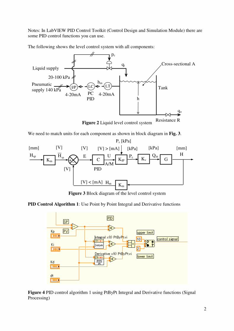
Notes: In LabVIEW PID Control Toolkit (Control Design and Simulation Module) there are
some PID control functions you can use.
The following shows the level control system with all components:
Figure 2 Liquid level control system
We need to match units for each component as shown in block diagram in Fig. 3.
Figure 3 Block diagram of the level control system
PID Control Algorithm 1: Use Point by Point Integral and Derivative functions
Figure 4 PID control algorithm 1 using PtByPt Integral and Derivative functions (Signal
Processing)
h
qo
LT LCI/P
qi
pc
hm Pneumatic
supply 140 kPa
Cross-sectional A
Tank
Resistance R
PC
PID 4-20mA 4-20mA
Liquid supply
20-100 kPa
KIP C + _ spH H
Km
E U Km
Hsp Kv G
Ps [kPa]
[mm] [V]
[V]
[V] [V] > [mA] [kPa] [kPa]
Pc Qin
Hm [V] < [mA]
[mm]
A/M PID

3
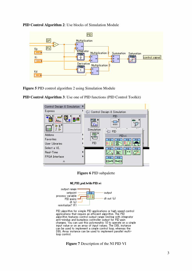
PID Control Algorithm 2: Use blocks of Simulation Module
Figure 5 PID control algorithm 2 using Simulation Module
PID Control Algorithm 3: Use one of PID functions (PID Control Toolkit)
Figure 6 PID subpalette
Figure 7 Description of the NI PID VI

4
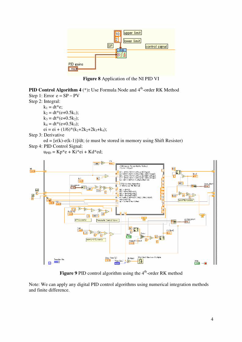
Figure 8 Application of the NI PID VI
PID Control Algorithm 4 (*): Use Formula Node and 4th
-order RK Method
Step 1: Error PVSPe −=
Step 2: Integral:
k1 = dt*e;
k2 = dt*(e+0.5k1);
k3 = dt*(e+0.5k2);
k4 = dt*(e+0.5k3);
ei = ei + (1/6)*(k1+2k2+2k3+k4);
Step 3: Derivative
ed = [e(k)-e(k-1)]/dt; (e must be stored in memory using Shift Resister)
Step 4: PID Control Signal:
uPID = Kp*e + Ki*ei + Kd*ed;
Figure 9 PID control algorithm using the 4th
-order RK method
Note: We can apply any digital PID control algorithms using numerical integration methods
and finite difference.
5
Hands-on Exercise 1 PID Control Algorithm 1
• Open the On-Off Level Control > Save as PIDLevelControlSysSim01.vi
Refer to PID Control Algorithm 1:
• Save the VI frequently
• Run and test the VI functionality
• Select some values of control gains such that the system response has small overshoot
and zero offset.
(Estimated time: 30 minute)
Hands-on Exercise 2 PID Control Algorithm 2
• Save the VI we created in Exercise 1 as PIDLevelControlSysSim02.vi
Refer to PID Control Algorithm 2:
• Save the VI frequently
• Run and test the VI functionality
• Select some values of control gains such that the system response has small overshoot
and zero offset.
(Estimated time: 30 minute)
Hands-on Exercise 3 PID Controller with a PID function
• Save the VI we created in Exercise 2 as PIDLevelControlSysSim03.vi
Refer to PID Control Algorithm 3:
• Save the VI frequently
• Run and test the VI functionality
• Select some values of control gains such that the system response has small overshoot
and zero offset.
(Estimated time: 30 minute)
Hands-on Exercise 4 PID control algorithm using Formula Node and RK method
• Open the On-Off Level Control > Save as PIDLevelControlSysSim04.vi (we can start
from an earlier version of level system simulator)
• Modify in a way that the Simulation Loop is replaced with a While Loop.
Refer to PID Control Algorithm 4:
• Save the VI frequently
• Run and test the VI functionality
• Select some values of control gains such that the system response has small overshoot
and zero offset.
(Estimated time: 1 hour)
Conclusions
At this point the following LOs have been met:
• Design PID controllers with LabVIEW
• Implement PID control algorithms for level control
• Simulate PID control systems with Auto/Man switch mode
• Use PtByPt Integral and Derivative functions
6
• Use PID Control functions of the PID Control Toolkit
• Use Formula Node and 4th
-order RK Method
Further Reading and References
Finn Haugen’s website
http://techteach.no/labview/lv85/pid_control/index.htm
Follow-up Exercises
Make a LabVIEW simulation for the temperature control system (case study) [pp2.46-2.47].
1
Tutorial 7 - PID Control System (JEE344 Applied Control Engineering)
Aim
• To design and simulate an PID control system
• To use simulation as a diagnostic tool to improve control system performance and
select control gains
Learning Outcomes
• Design PID controllers with LabVIEW
• Implement PID control algorithms for level control
• Simulate PID control systems with Auto/Man switch mode
• Use PtByPt Integral and Derivative functions
• Use PID Control functions of the PID Control Toolkit
• Use Formula Node and 4th
-order RK Method
PID Control Algorithms– Design and Simulation with LabVIEW
The PID control law is:
dt
deKedtKeKu d
t
0
ip ++= ∫ or
++= ∫ dt
deTedt
T
1eKu d
t
0i
p
pK
100PB = ;
i
p
iT
KK = ; dpd TKK =
Transfer function:
sKs
KK
E
Ud
ip ++= or
++= sT
sT
11K
E
Ud
i
p
Block diagram algorithm for PID controller with Auto/Man mode
Figure 1 Block diagram algorithm for PID control with Auto/Man switch mode
uin
Kp
SP
Integral
Subtract Multiply
Sum
(Compound
Arithmetic)
PV
Auto
4
Select
To Actuator
OP
(Control signal)
PID Controller
Auto/Man
KI
Multiply
KD
Multiply uin
Derivative
Comparator
P
I
D
2
Notes: In LabVIEW PID Control Toolkit (Control Design and Simulation Module) there are
some PID control functions you can use.
The following shows the level control system with all components:
Figure 2 Liquid level control system
We need to match units for each component as shown in block diagram in Fig. 3.
Figure 3 Block diagram of the level control system
PID Control Algorithm 1: Use Point by Point Integral and Derivative functions
Figure 4 PID control algorithm 1 using PtByPt Integral and Derivative functions (Signal
Processing)
h
qo
LT LCI/P
qi
pc
hm Pneumatic
supply 140 kPa
Cross-sectional A
Tank
Resistance R
PC
PID 4-20mA 4-20mA
Liquid supply
20-100 kPa
KIP C + _ spH H
Km
E U Km
Hsp Kv G
Ps [kPa]
[mm] [V]
[V]
[V] [V] > [mA] [kPa] [kPa]
Pc Qin
Hm [V] < [mA]
[mm]
A/M PID

3
PID Control Algorithm 2: Use blocks of Simulation Module
Figure 5 PID control algorithm 2 using Simulation Module
PID Control Algorithm 3: Use one of PID functions (PID Control Toolkit)
Figure 6 PID subpalette
Figure 7 Description of the NI PID VI

4
Figure 8 Application of the NI PID VI
PID Control Algorithm 4 (*): Use Formula Node and 4th
-order RK Method
Step 1: Error PVSPe −=
Step 2: Integral:
k1 = dt*e;
k2 = dt*(e+0.5k1);
k3 = dt*(e+0.5k2);
k4 = dt*(e+0.5k3);
ei = ei + (1/6)*(k1+2k2+2k3+k4);
Step 3: Derivative
ed = [e(k)-e(k-1)]/dt; (e must be stored in memory using Shift Resister)
Step 4: PID Control Signal:
uPID = Kp*e + Ki*ei + Kd*ed;
Figure 9 PID control algorithm using the 4th
-order RK method
Note: We can apply any digital PID control algorithms using numerical integration methods
and finite difference.

5
Hands-on Exercise 1 PID Control Algorithm 1
• Open the On-Off Level Control > Save as PIDLevelControlSysSim01.vi
Refer to PID Control Algorithm 1:
• Save the VI frequently
• Run and test the VI functionality
• Select some values of control gains such that the system response has small overshoot
and zero offset.
(Estimated time: 30 minute)
Hands-on Exercise 2 PID Control Algorithm 2
• Save the VI we created in Exercise 1 as PIDLevelControlSysSim02.vi
Refer to PID Control Algorithm 2:
• Save the VI frequently
• Run and test the VI functionality
• Select some values of control gains such that the system response has small overshoot
and zero offset.
(Estimated time: 30 minute)
Hands-on Exercise 3 PID Controller with a PID function
• Save the VI we created in Exercise 2 as PIDLevelControlSysSim03.vi
Refer to PID Control Algorithm 3:
• Save the VI frequently
• Run and test the VI functionality
• Select some values of control gains such that the system response has small overshoot
and zero offset.
(Estimated time: 30 minute)
Hands-on Exercise 4 PID control algorithm using Formula Node and RK method
• Open the On-Off Level Control > Save as PIDLevelControlSysSim04.vi (we can start
from an earlier version of level system simulator)
• Modify in a way that the Simulation Loop is replaced with a While Loop.
Refer to PID Control Algorithm 4:
• Save the VI frequently
• Run and test the VI functionality
• Select some values of control gains such that the system response has small overshoot
and zero offset.
(Estimated time: 1 hour)
Conclusions
At this point the following LOs have been met:
• Design PID controllers with LabVIEW
• Implement PID control algorithms for level control
• Simulate PID control systems with Auto/Man switch mode
• Use PtByPt Integral and Derivative functions

6
• Use PID Control functions of the PID Control Toolkit
• Use Formula Node and 4th
-order RK Method
Further Reading and References
Finn Haugen’s website
http://techteach.no/labview/lv85/pid_control/index.htm
Follow-up Exercises
Make a LabVIEW simulation for the temperature control system (case study) [pp2.46-2.47].

1
Tutorial 7 - PID Control System (JEE344 Applied Control Engineering)
Aim
• To design and simulate an PID control system
• To use simulation as a diagnostic tool to improve control system performance and
select control gains
Learning Outcomes
• Design PID controllers with LabVIEW
• Implement PID control algorithms for level control
• Simulate PID control systems with Auto/Man switch mode
• Use PtByPt Integral and Derivative functions
• Use PID Control functions of the PID Control Toolkit
• Use Formula Node and 4th
-order RK Method
PID Control Algorithms– Design and Simulation with LabVIEW
The PID control law is:
dt
deKedtKeKu d
t
0
ip ++= ∫ or
++= ∫ dt
deTedt
T
1eKu d
t
0i
p
pK
100PB = ;
i
p
iT
KK = ; dpd TKK =
Transfer function:
sKs
KK
E
Ud
ip ++= or
++= sT
sT
11K
E
Ud
i
p
Block diagram algorithm for PID controller with Auto/Man mode
Figure 1 Block diagram algorithm for PID control with Auto/Man switch mode
uin
Kp
SP
Integral
Subtract Multiply
Sum
(Compound
Arithmetic)
PV
Auto
4
Select
To Actuator
OP
(Control signal)
PID Controller
Auto/Man
KI
Multiply
KD
Multiply uin
Derivative
Comparator
P
I
D

2
Notes: In LabVIEW PID Control Toolkit (Control Design and Simulation Module) there are
some PID control functions you can use.
The following shows the level control system with all components:
Figure 2 Liquid level control system
We need to match units for each component as shown in block diagram in Fig. 3.
Figure 3 Block diagram of the level control system
PID Control Algorithm 1: Use Point by Point Integral and Derivative functions
Figure 4 PID control algorithm 1 using PtByPt Integral and Derivative functions (Signal
Processing)
h
qo
LT LCI/P
qi
pc
hm Pneumatic
supply 140 kPa
Cross-sectional A
Tank
Resistance R
PC
PID 4-20mA 4-20mA
Liquid supply
20-100 kPa
KIP C + _ spH H
Km
E U Km
Hsp Kv G
Ps [kPa]
[mm] [V]
[V]
[V] [V] > [mA] [kPa] [kPa]
Pc Qin
Hm [V] < [mA]
[mm]
A/M PID

3
PID Control Algorithm 2: Use blocks of Simulation Module
Figure 5 PID control algorithm 2 using Simulation Module
PID Control Algorithm 3: Use one of PID functions (PID Control Toolkit)
Figure 6 PID subpalette
Figure 7 Description of the NI PID VI
4
Figure 8 Application of the NI PID VI
PID Control Algorithm 4 (*): Use Formula Node and 4th
-order RK Method
Step 1: Error PVSPe −=
Step 2: Integral:
k1 = dt*e;
k2 = dt*(e+0.5k1);
k3 = dt*(e+0.5k2);
k4 = dt*(e+0.5k3);
ei = ei + (1/6)*(k1+2k2+2k3+k4);
Step 3: Derivative
ed = [e(k)-e(k-1)]/dt; (e must be stored in memory using Shift Resister)
Step 4: PID Control Signal:
uPID = Kp*e + Ki*ei + Kd*ed;
Figure 9 PID control algorithm using the 4th
-order RK method
Note: We can apply any digital PID control algorithms using numerical integration methods
and finite difference.

5
Hands-on Exercise 1 PID Control Algorithm 1
• Open the On-Off Level Control > Save as PIDLevelControlSysSim01.vi
Refer to PID Control Algorithm 1:
• Save the VI frequently
• Run and test the VI functionality
• Select some values of control gains such that the system response has small overshoot
and zero offset.
(Estimated time: 30 minute)
Hands-on Exercise 2 PID Control Algorithm 2
• Save the VI we created in Exercise 1 as PIDLevelControlSysSim02.vi
Refer to PID Control Algorithm 2:
• Save the VI frequently
• Run and test the VI functionality
• Select some values of control gains such that the system response has small overshoot
and zero offset.
(Estimated time: 30 minute)
Hands-on Exercise 3 PID Controller with a PID function
• Save the VI we created in Exercise 2 as PIDLevelControlSysSim03.vi
Refer to PID Control Algorithm 3:
• Save the VI frequently
• Run and test the VI functionality
• Select some values of control gains such that the system response has small overshoot
and zero offset.
(Estimated time: 30 minute)
Hands-on Exercise 4 PID control algorithm using Formula Node and RK method
• Open the On-Off Level Control > Save as PIDLevelControlSysSim04.vi (we can start
from an earlier version of level system simulator)
• Modify in a way that the Simulation Loop is replaced with a While Loop.
Refer to PID Control Algorithm 4:
• Save the VI frequently
• Run and test the VI functionality
• Select some values of control gains such that the system response has small overshoot
and zero offset.
(Estimated time: 1 hour)
Conclusions
At this point the following LOs have been met:
• Design PID controllers with LabVIEW
• Implement PID control algorithms for level control
• Simulate PID control systems with Auto/Man switch mode
• Use PtByPt Integral and Derivative functions

6
• Use PID Control functions of the PID Control Toolkit
• Use Formula Node and 4th
-order RK Method
Further Reading and References
Finn Haugen’s website
http://techteach.no/labview/lv85/pid_control/index.htm
Follow-up Exercises
Make a LabVIEW simulation for the temperature control system (case study) [pp2.46-2.47].

1
Tutorial 7 - PID Control System (JEE344 Applied Control Engineering)
Aim
• To design and simulate an PID control system
• To use simulation as a diagnostic tool to improve control system performance and
select control gains
Learning Outcomes
• Design PID controllers with LabVIEW
• Implement PID control algorithms for level control
• Simulate PID control systems with Auto/Man switch mode
• Use PtByPt Integral and Derivative functions
• Use PID Control functions of the PID Control Toolkit
• Use Formula Node and 4th
-order RK Method
PID Control Algorithms– Design and Simulation with LabVIEW
The PID control law is:
dt
deKedtKeKu d
t
0
ip ++= ∫ or
++= ∫ dt
deTedt
T
1eKu d
t
0i
p
pK
100PB = ;
i
p
iT
KK = ; dpd TKK =
Transfer function:
sKs
KK
E
Ud
ip ++= or
++= sT
sT
11K
E
Ud
i
p
Block diagram algorithm for PID controller with Auto/Man mode
Figure 1 Block diagram algorithm for PID control with Auto/Man switch mode
uin
Kp
SP
Integral
Subtract Multiply
Sum
(Compound
Arithmetic)
PV
Auto
4
Select
To Actuator
OP
(Control signal)
PID Controller
Auto/Man
KI
Multiply
KD
Multiply uin
Derivative
Comparator
P
I
D

2
Notes: In LabVIEW PID Control Toolkit (Control Design and Simulation Module) there are
some PID control functions you can use.
The following shows the level control system with all components:
Figure 2 Liquid level control system
We need to match units for each component as shown in block diagram in Fig. 3.
Figure 3 Block diagram of the level control system
PID Control Algorithm 1: Use Point by Point Integral and Derivative functions
Figure 4 PID control algorithm 1 using PtByPt Integral and Derivative functions (Signal
Processing)
h
qo
LT LCI/P
qi
pc
hm Pneumatic
supply 140 kPa
Cross-sectional A
Tank
Resistance R
PC
PID 4-20mA 4-20mA
Liquid supply
20-100 kPa
KIP C + _ spH H
Km
E U Km
Hsp Kv G
Ps [kPa]
[mm] [V]
[V]
[V] [V] > [mA] [kPa] [kPa]
Pc Qin
Hm [V] < [mA]
[mm]
A/M PID

3
PID Control Algorithm 2: Use blocks of Simulation Module
Figure 5 PID control algorithm 2 using Simulation Module
PID Control Algorithm 3: Use one of PID functions (PID Control Toolkit)
Figure 6 PID subpalette
Figure 7 Description of the NI PID VI

4
Figure 8 Application of the NI PID VI
PID Control Algorithm 4 (*): Use Formula Node and 4th
-order RK Method
Step 1: Error PVSPe −=
Step 2: Integral:
k1 = dt*e;
k2 = dt*(e+0.5k1);
k3 = dt*(e+0.5k2);
k4 = dt*(e+0.5k3);
ei = ei + (1/6)*(k1+2k2+2k3+k4);
Step 3: Derivative
ed = [e(k)-e(k-1)]/dt; (e must be stored in memory using Shift Resister)
Step 4: PID Control Signal:
uPID = Kp*e + Ki*ei + Kd*ed;
Figure 9 PID control algorithm using the 4th
-order RK method
Note: We can apply any digital PID control algorithms using numerical integration methods
and finite difference.

5
Hands-on Exercise 1 PID Control Algorithm 1
• Open the On-Off Level Control > Save as PIDLevelControlSysSim01.vi
Refer to PID Control Algorithm 1:
• Save the VI frequently
• Run and test the VI functionality
• Select some values of control gains such that the system response has small overshoot
and zero offset.
(Estimated time: 30 minute)
Hands-on Exercise 2 PID Control Algorithm 2
• Save the VI we created in Exercise 1 as PIDLevelControlSysSim02.vi
Refer to PID Control Algorithm 2:
• Save the VI frequently
• Run and test the VI functionality
• Select some values of control gains such that the system response has small overshoot
and zero offset.
(Estimated time: 30 minute)
Hands-on Exercise 3 PID Controller with a PID function
• Save the VI we created in Exercise 2 as PIDLevelControlSysSim03.vi
Refer to PID Control Algorithm 3:
• Save the VI frequently
• Run and test the VI functionality
• Select some values of control gains such that the system response has small overshoot
and zero offset.
(Estimated time: 30 minute)
Hands-on Exercise 4 PID control algorithm using Formula Node and RK method
• Open the On-Off Level Control > Save as PIDLevelControlSysSim04.vi (we can start
from an earlier version of level system simulator)
• Modify in a way that the Simulation Loop is replaced with a While Loop.
Refer to PID Control Algorithm 4:
• Save the VI frequently
• Run and test the VI functionality
• Select some values of control gains such that the system response has small overshoot
and zero offset.
(Estimated time: 1 hour)
Conclusions
At this point the following LOs have been met:
• Design PID controllers with LabVIEW
• Implement PID control algorithms for level control
• Simulate PID control systems with Auto/Man switch mode
• Use PtByPt Integral and Derivative functions

6
• Use PID Control functions of the PID Control Toolkit
• Use Formula Node and 4th
-order RK Method
Further Reading and References
Finn Haugen’s website
http://techteach.no/labview/lv85/pid_control/index.htm
Follow-up Exercises
Make a LabVIEW simulation for the temperature control system (case study) [pp2.46-2.47].

1
Tutorial 7 - PID Control System (JEE344 Applied Control Engineering)
Aim
• To design and simulate an PID control system
• To use simulation as a diagnostic tool to improve control system performance and
select control gains
Learning Outcomes
• Design PID controllers with LabVIEW
• Implement PID control algorithms for level control
• Simulate PID control systems with Auto/Man switch mode
• Use PtByPt Integral and Derivative functions
• Use PID Control functions of the PID Control Toolkit
• Use Formula Node and 4th
-order RK Method
PID Control Algorithms– Design and Simulation with LabVIEW
The PID control law is:
dt
deKedtKeKu d
t
0
ip ++= ∫ or
++= ∫ dt
deTedt
T
1eKu d
t
0i
p
pK
100PB = ;
i
p
iT
KK = ; dpd TKK =
Transfer function:
sKs
KK
E
Ud
ip ++= or
++= sT
sT
11K
E
Ud
i
p
Block diagram algorithm for PID controller with Auto/Man mode
Figure 1 Block diagram algorithm for PID control with Auto/Man switch mode
uin
Kp
SP
Integral
Subtract Multiply
Sum
(Compound
Arithmetic)
PV
Auto
4
Select
To Actuator
OP
(Control signal)
PID Controller
Auto/Man
KI
Multiply
KD
Multiply uin
Derivative
Comparator
P
I
D

2
Notes: In LabVIEW PID Control Toolkit (Control Design and Simulation Module) there are
some PID control functions you can use.
The following shows the level control system with all components:
Figure 2 Liquid level control system
We need to match units for each component as shown in block diagram in Fig. 3.
Figure 3 Block diagram of the level control system
PID Control Algorithm 1: Use Point by Point Integral and Derivative functions
Figure 4 PID control algorithm 1 using PtByPt Integral and Derivative functions (Signal
Processing)
h
qo
LT LCI/P
qi
pc
hm Pneumatic
supply 140 kPa
Cross-sectional A
Tank
Resistance R
PC
PID 4-20mA 4-20mA
Liquid supply
20-100 kPa
KIP C + _ spH H
Km
E U Km
Hsp Kv G
Ps [kPa]
[mm] [V]
[V]
[V] [V] > [mA] [kPa] [kPa]
Pc Qin
Hm [V] < [mA]
[mm]
A/M PID
3
PID Control Algorithm 2: Use blocks of Simulation Module
Figure 5 PID control algorithm 2 using Simulation Module
PID Control Algorithm 3: Use one of PID functions (PID Control Toolkit)
Figure 6 PID subpalette
Figure 7 Description of the NI PID VI

4
Figure 8 Application of the NI PID VI
PID Control Algorithm 4 (*): Use Formula Node and 4th
-order RK Method
Step 1: Error PVSPe −=
Step 2: Integral:
k1 = dt*e;
k2 = dt*(e+0.5k1);
k3 = dt*(e+0.5k2);
k4 = dt*(e+0.5k3);
ei = ei + (1/6)*(k1+2k2+2k3+k4);
Step 3: Derivative
ed = [e(k)-e(k-1)]/dt; (e must be stored in memory using Shift Resister)
Step 4: PID Control Signal:
uPID = Kp*e + Ki*ei + Kd*ed;
Figure 9 PID control algorithm using the 4th
-order RK method
Note: We can apply any digital PID control algorithms using numerical integration methods
and finite difference.

5
Hands-on Exercise 1 PID Control Algorithm 1
• Open the On-Off Level Control > Save as PIDLevelControlSysSim01.vi
Refer to PID Control Algorithm 1:
• Save the VI frequently
• Run and test the VI functionality
• Select some values of control gains such that the system response has small overshoot
and zero offset.
(Estimated time: 30 minute)
Hands-on Exercise 2 PID Control Algorithm 2
• Save the VI we created in Exercise 1 as PIDLevelControlSysSim02.vi
Refer to PID Control Algorithm 2:
• Save the VI frequently
• Run and test the VI functionality
• Select some values of control gains such that the system response has small overshoot
and zero offset.
(Estimated time: 30 minute)
Hands-on Exercise 3 PID Controller with a PID function
• Save the VI we created in Exercise 2 as PIDLevelControlSysSim03.vi
Refer to PID Control Algorithm 3:
• Save the VI frequently
• Run and test the VI functionality
• Select some values of control gains such that the system response has small overshoot
and zero offset.
(Estimated time: 30 minute)
Hands-on Exercise 4 PID control algorithm using Formula Node and RK method
• Open the On-Off Level Control > Save as PIDLevelControlSysSim04.vi (we can start
from an earlier version of level system simulator)
• Modify in a way that the Simulation Loop is replaced with a While Loop.
Refer to PID Control Algorithm 4:
• Save the VI frequently
• Run and test the VI functionality
• Select some values of control gains such that the system response has small overshoot
and zero offset.
(Estimated time: 1 hour)
Conclusions
At this point the following LOs have been met:
• Design PID controllers with LabVIEW
• Implement PID control algorithms for level control
• Simulate PID control systems with Auto/Man switch mode
• Use PtByPt Integral and Derivative functions

6
• Use PID Control functions of the PID Control Toolkit
• Use Formula Node and 4th
-order RK Method
Further Reading and References
Finn Haugen’s website
http://techteach.no/labview/lv85/pid_control/index.htm
Follow-up Exercises
Make a LabVIEW simulation for the temperature control system (case study) [pp2.46-2.47].
Top Related