


Languages
Pages
Legal


Promat International NVBormstraat 24TisseltBE – 2830 BELGIUMTel : +32 15 71 81 00Fax : +32 15 71 81 09http://[email protected]
American Commercial, Inc.200 Bob Morrison Blvd Bristol, VA 24201-3810Tel : +1 276 466 2743 Fax : +1 276 669 0940http://[email protected]
“The reverse side of this flap details sections of the original NFPA 502 text, related to fire safety issues. Please open the flap.”
The authors are grateful to the
NFPA organization for allowing
them to use sections of the original
NFPA 502 standard text.
Tunnel Fire ProtectionA conversion from NFPA 502 standard to practical systems and tested solutions
Exclusive Promat distributor for the US tunnel market:
Promat Headquarters:
www.promat-tunnel.com
CO
NC
RE
TE
PR
OT
EC
TIO
NF
IRE
CU
RV
ES
/ GE
NE
RA
LD
OO
RS
AIR
DU
CT
SC
AB
LE
S &
SE
RV
ICE
S
INTRODUCTION
This document is based on the NFPA 502, Standard for Road Tunnels, Bridges,
and Other Limited Access Highways, 2004 Edition.
The purpose is to have a conversion document from this standard to practical
systems that have been tested by international fire-research laboratories, thus
enabling designers and engineers to select fire-safe solutions for their project.
The systems as shown in this document are a selection of the wide range of
tested Promat constructions. Please consult the Promat technical department
for further details or alternatives in order to meet project specific requirements.
The authors are grateful to the
NFPA organization for allowing
them to use sections of the original
NFPA 502 standard text.

CO
NC
RE
TE
PR
OT
EC
TIO
NF
IRE
CU
RV
ES
/ GE
NE
RA
LD
OO
RS
AIR
DU
CT
SC
AB
LE
S &
SE
RV
ICE
SCHAPTER Description # Official NFPA 502 Standard Text
1. Administration Scope 1.1.1 This standard provides fire protection and fire life safety requirements for limited 4 - 5 access highways, road tunnels, bridges, elevated highways, depressed highways, and roadways that are located beneath air-right structures.
Scope 1.1.2 This standard establishes minimum requirements for each of the identified facilities.
Purpose 1.2 The purpose of this standard is to establish minimum criteria that provide protection from fire and its related hazards.
Retroactivity 1.4.1 … Where specified, the provisions of this standard shall be retroactive.
Retroactivity 1.4.2 In those cases where the authority having jurisdiction determines that the existing situation presents an unacceptable degree of risk, the authority having jurisdiction shall be permitted to apply retroactively any portions of this standard deemed appropriate.
4. General Requirements Characteristics 4.1 The level of fire protection necessary for the entire facility shall be achieved by implementing the of Fire Protection requirements of this standard for each subsystem.
Fire Protection 4.3.1 As a minimum the following factors shall be evaluated in an engineering analysis and where (1) : 4 - 5 and Fire Life applying the fire and life safety requirements for the facilities covered by this standard: ... (6) : 9 - 12 Safety Factor (1) Protection of life, (6) Exposure of structure to elevated temperatures, (8d) Built-in fire protection (8d): 26 - 29 features, such as ventilation systems, (9) Protection of facility components, ... (9) : 26 - 31
7. Road Tunnels Protection of 7.3 Regardless of tunnel length, all primary structural concrete and steel elements shall undergo 6 - 26 Concrete and a fire engineering analysis to ensure that the tunnel structure can withstand the anticipated Steel Structures fire severity based on the type of traffic to be permitted.
Annex A Explanatory A.7.3 “Concrete and steel structural elements should have a 4-hour fire resistance rating in accordance 6 - 26, page 7 Material with the time/temperature curve, for example, ANSI/UL 1709. Concrete and steel structural elements (RWS curve) with a minimum fire resistance rating of 2 hours in accordance with ANSI/UL 1709 should be in particular permitted where the anticipated design fire size is 20 MW or less and flammable liquids in bulk (hazardous) cargo are prohibited from the tunnel. Tunnels with cast in-situ concrete structural elements should be protected such that the temperature of the concrete surface does not exceed 380°C (716°F) after the defined fire exposure conditions. The temperature of the steel reinforcement within the concrete [assuming a minimum cover of 25 mm (1 in.)] should not exceed 250°C (482°F) under the same fire exposure conditions. Tunnels with pre-cast (high strength) concrete elements should be protected such that explosive spalling is eliminated under the defined fire exposure conditions. Tunnels with steel or cast iron linings should be similarly protected depending on the design fire size.
12. Emergency Response Emergencies 12.2 The following typical incidents shall be considered during the development of facility 4 - 5 & 9 - 14 emergency response plans: … (10) Damage to structures from impact and heat exposure ...
7. Road Tunnels Doors 7.17.4.3 Doors shall be listed fire doors with a minimum 1-hour rating and shall be installed 31 in accordance with NFPA 80.
10. Emergency Ventilation Smoke control 10.2.1 The emergency ventilation system shall provide a means for controlling smoke. 26 - 29
Smoke control 10.2.2 In all cases, the desired goal shall be to provide an evacuation path for motorists who are exiting from the tunnel and to facilitate fire-fighting operations. 26 - 29
11. Electrical Systems General 11.1.2 “The electrical systems shall maintain ventilation, illumination, communications, drainage, and water supply; shall identify areas of refuge, exits, and exit routes; and shall provide remote annunciation and alarm under all operating and emergency modes associated with the facility” 30
Materials 11.3.1 Materials that are manufactured for use as conduits, raceways, ducts, cabinets, and equipment enclosures and their surface finish materials, as installed, shall be capable of being subjected to temperatures up to 316°C (600°F) for 1 hour without supporting combustion and without loss of structural integrity. 34 - 35
Power Source 11.4 … The following systems shall be provided with reliable power for a fire emergency: (1) Lighting, (2) Lighting for means of egress and areas of refuge, (3) Exit signs, (4) Communications, (5) Tunnel drainage and fire pumps, (6) Ventilation during a fire emergency 30
Reference to “Promat Technical Note on The Fire Protection of Tunnel Structures & Services (07/2004)”

“Full scale tests in the Runehamar tunnel in Norway (September 2003) have shown that the RWS fire curve was best simulated”
FIRE CURVES
In recent years a great deal of research has taken place internationally to ascertain
the types of fire which could occur in tunnel and underground spaces. This research
has taken place in both real, disused tunnels and laboratory conditions.
As a consequence of the data obtained from these tests, a series of time/
temperature curves for the various exposures have been developed as detailed.
Cellulosic (ASTM/ISO) curve:Standard fire tests to which specimens of constructions are exposed to are
based on the use of the Cellulosic time/temperature curve, as defined in various
national standards, e.g. ASTM, ISO 834, BS 476 : part 20, DIN 4102, AS 1530
etc. Although there are other types of fire test curves e.g. BS 7436, the curve as
detailed below for this exposure is the lowest used in normal practice. This curve
is based on the burning rate of the materials found in general building materials
and contents.
HydroCarbon curve (HC), similar to ANSI/UL 1709:Although the Cellulosic curve has been in use for many years, it soon became
apparent that the burning rates for certain materials e.g. petrol gas, chemicals
etc, were well in excess of the rate at which for instance, timber would burn. As
such, there was a need for an alternative exposure for the purpose of carrying
out tests on structures and materials used within the petrochemical industry, and
thus the hydrocarbon curve was developed.
The hydrocarbon curve is applicable where small petroleum fires might occur,
i.e. car fuel tanks, petrol or oil tankers, certain chemical tankers etc. In fact,
although the hydrocarbon curve is based on a standardized type fire, there are
numerous types of fire associated with petrochemical fuels.

CO
NC
RE
TE
PR
OT
EC
TIO
NF
IRE
CU
RV
ES
/ GE
NE
RA
LD
OO
RS
AIR
DU
CT
SC
AB
LE
S &
SE
RV
ICE
S
I
HydroCarbon Modified curve (HCM, France):Derived from the above-mentioned Hydrocarbon curve, the French tunnel regulation asks for an
increased version of that Hydrocarbon curve, the so called HydroCarbon Modified curve (HCM).
The maximum temperature of the HCM curve is 1300 ºC (2372 F) instead of the 1080 ºC (1976 F),
standard HC curve. However, the temperature gradient in the first few minutes of the HCM fire is as
severe as all Hydrocarbon based fires (RWS, HCM, HC), possibly causing a temperature shock to the
surrounding concrete structure and concrete spalling as a result of it.
RABT-ZTV curve (Germany):The RABT curve was developed in Germany as a result of a series of test programmes such as the
Eureka project. In the RABT curve, the temperature rise is very rapid up to 1200 °C (2192 F) within
5 minutes, faster than the Hydrocarbon curve which rises only to 1100 °C (2012 F) after 60 minutes.
The duration of the 1200 °C (2192 F) exposure is shorter than other curves with the temperature drop off
starting to occur at 30 minutes.
This test curve can be adapted to meet specific requirements, in testing to this exposure, the heat rise
is very rapid, but is only held for a period of 30 minutes, similar to the sort of temperature rise you would
expect from a simple truck fire, but with a cooling down period of 110 minutes. If required, for specific
types of exposure, the heating period can be extended to 60 minutes or more, but the 110 minute cooling
period would still be applied.
RWS curve (The Netherlands):The RWS curve was developed by the Rijkswaterstaat, Ministry of Transport in the Netherlands.
This curve is based on the assumption that in a worst case scenario, a fuel, oil or petrol tanker fire with a
fire load of 300MW could occur, lasting up to 120 minutes, reaching a maximum temperature of 1350 °C
(2462 F) after 1 hour.
The RWS curve was based on the results of testing carried out by TNO in the Netherlands in 1979.
The difference between the RWS and the Hydrocarbon curve, is that the latter is based on the
temperatures that would be expected from a fire occurring within a relatively open space, where some
dissipation of the heat would occur, whereas the RWS curve is based on the sort of temperature you
would find when a fire occurs in an enclosed area, such as a tunnel, where there is little or no chance of
heat dissipating into the surrounding atmosphere.
The RWS curve simulates the initial rapid growth of a fire using a petroleum tanker as the source, and the
gradual drop in temperatures to be expected as the fuel load is burnt off.
The failure criteria, for specimens exposed to the RWS time/temperature curve is that the temperature
of the interface between the concrete slab and the protective covering should not exceed 380 °C (716 F)
and the temperature on the reinforcement should not exceed 250 °C (482 F) (based on a concrete cover
of 25 mm / 1 inch).
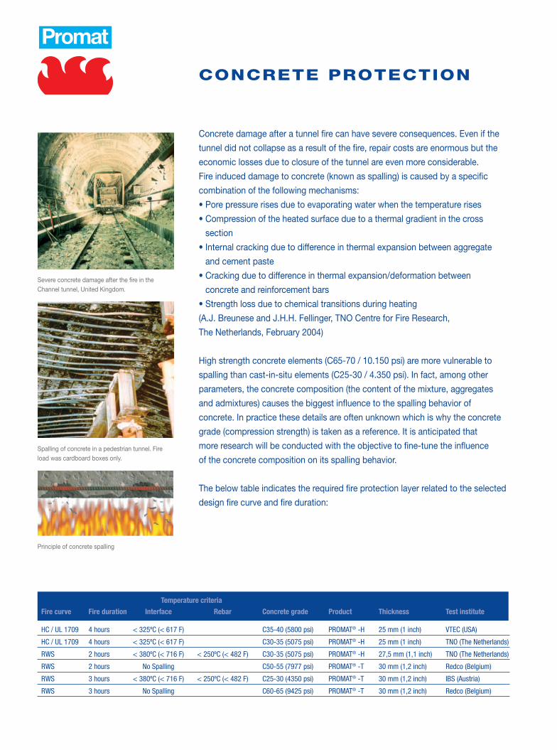
Severe concrete damage after the fire in the Channel tunnel, United Kingdom.
Spalling of concrete in a pedestrian tunnel. Fire load was cardboard boxes only.
Principle of concrete spalling
CONCRETE PROTECTION
Concrete damage after a tunnel fire can have severe consequences. Even if the
tunnel did not collapse as a result of the fire, repair costs are enormous but the
economic losses due to closure of the tunnel are even more considerable.
Fire induced damage to concrete (known as spalling) is caused by a specific
combination of the following mechanisms:
• Pore pressure rises due to evaporating water when the temperature rises
• Compression of the heated surface due to a thermal gradient in the cross
section
• Internal cracking due to difference in thermal expansion between aggregate
and cement paste
• Cracking due to difference in thermal expansion/deformation between
concrete and reinforcement bars
• Strength loss due to chemical transitions during heating
(A.J. Breunese and J.H.H. Fellinger, TNO Centre for Fire Research,
The Netherlands, February 2004)
High strength concrete elements (C65-70 / 10.150 psi) are more vulnerable to
spalling than cast-in-situ elements (C25-30 / 4.350 psi). In fact, among other
parameters, the concrete composition (the content of the mixture, aggregates
and admixtures) causes the biggest influence to the spalling behavior of
concrete. In practice these details are often unknown which is why the concrete
grade (compression strength) is taken as a reference. It is anticipated that
more research will be conducted with the objective to fine-tune the influence
of the concrete composition on its spalling behavior.
The below table indicates the required fire protection layer related to the selected
design fire curve and fire duration:
Temperature criteria
Fire curve Fire duration Interface Rebar Concrete grade Product Thickness Test institute
HC / UL 1709 4 hours < 325ºC (< 617 F) C35-40 (5800 psi) PROMAT® -H 25 mm (1 inch) VTEC (USA)
HC / UL 1709 4 hours < 325ºC (< 617 F) C30-35 (5075 psi) PROMAT® -H 25 mm (1 inch) TNO (The Netherlands)
RWS 2 hours < 380ºC (< 716 F) < 250ºC (< 482 F) C30-35 (5075 psi) PROMAT® -H 27,5 mm (1,1 inch) TNO (The Netherlands)
RWS 2 hours No Spalling C50-55 (7977 psi) PROMAT® -T 30 mm (1,2 inch) Redco (Belgium)
RWS 3 hours < 380ºC (< 716 F) < 250ºC (< 482 F) C25-30 (4350 psi) PROMAT® -T 30 mm (1,2 inch) IBS (Austria)
RWS 3 hours No Spalling C60-65 (9425 psi) PROMAT® -T 30 mm (1,2 inch) Redco (Belgium)

CO
NC
RE
TE
PR
OT
EC
TIO
NF
IRE
CU
RV
ES
/ GE
NE
RA
LD
OO
RS
AIR
DU
CT
SC
AB
LE
S &
SE
RV
ICE
S
PROMAT® -T boards applied in the Toulon tunnel, France. PROMAT® -T boards can be applied as a post-curved panel (curved on site).
Westerschelde tunnel, The Netherlands. Ceiling and wall application using PROMAT® -H boards. Curved application using PROMAT® -T boards.
Curved PROMAT® boards applied in the German Elb tunnel (4th tube), Hamburg.
Lost formwork system. The boards are laid onto the formwork. Partly inserted screws create the anchorage to the concrete.
Post installation system, by means of anchors.

Fire rated doors in the Westerschelde tunnel, The Netherlands.
DOORS
The design and construction of fire resisting doors is a complex operation
involving the skills and specialized knowledge of architects, fire experts, door
manufacturers and ironmongers.
The designer is the first in the line of those concerned with the provision of fire
doors. It is he who ascertains the requirements of the users and decides where
and in what form doors will be required. He also assembles the specialized
information from the other experts into a design for the complete door, and
arranges for the doors to be manufactured.
The first principle to be considered in relation to fire resisting doors is that in
most respects they are merely ordinary doors with certain additional features,
and throughout most of their life will be operating as such. Fire resisting doors,
therefore, have to be opened, closed, locked, latched, bolted, cleaned and main-
tained like any other door.
The following points are some of the factors, which should be considered
when determining the correct specification to ensure a doorset will provide the
required fire performance.
• Relevant test standards and fire/smoke requirements.
• Size of door leaf, generally the door-set should be no larger than the tested
door-set, but larger door-sets may be considered suitable for assessment
depending on the performance of the tested door-set.
• Number of door leaves, generally testing a double leaf door-set is more
onerous than a single leaf door-set. However, for tunnel applications single leaf
doors are most common.
• Action of door leaf, the performance of a door-set can vary considerably
depending on which side is exposed to the fire.
• Ironmongery, generally all ironmongery should have a melting point no less
than 1350 ºC (2462 F). The number, size and position of hinges can be critical.
Care should be taken when considering alternative ironmongery to that which
was tested.
• Door strips/smoke seals, Intumescent strips, and smoke seals if required, are
normally installed down the sides and along the top edge of the door leaf.
Alternatively, they can be inserted into the door-frame. Care should be taken
that they are fitted correctly around ironmongery.

CO
NC
RE
TE
PR
OT
EC
TIO
NF
IRE
CU
RV
ES
/ GE
NE
RA
LD
OO
RS
AIR
DU
CT
SC
AB
LE
S &
SE
RV
ICE
S
Hinged door, Hong Kong. Sliding door in the Schiphol Airport Viaduct, Amsterdam, The Netherlands.
Among others, following tunnels have been equipped with fire doors containing Promat materials:
- Westerschelde tunnel, The Netherlands, 2003
- Schiphol Airport Viaduct, The Netherlands, 2002
- Mont Blanc tunnel, France / Italy, 2000
- Hong Kong Airport tunnel, 1997
- Second Cross Harbour tunnel, Hong Kong, 1989
Following Promat materials have been applied for the production of these fire rated tunnel doors:
PROMAT ® -H and PROMAT ® -T boards for thermal insulation of the door leaf.
DURASTEEL® boards for impact resistance of tunnel doors.
PROMASEAL® intumescent (foaming) strips to seal the joint around the door leaf in case of fire.

Collapsed suspended ceiling in The Gotthard tunnel, Switzerland
Self supporting DURASTEEL® smoke extraction duct. Canary Wharf, United Kingdom
Cross section of tunnel showing air plenum construction, for smoke extraction purposes
Detail of steel sub-frame protected against fire with PROMAT® boards from both sides.1. PROMAT® -H or PROMAT® -T boards2. Framing system3. Hanger support system where required4. Connection to tunnel lining
AIRDUCTS
Especially circular and horseshoe shaped tunnels very often have a
suspended ceiling to create a ventilation duct within the tunnel roof space
(transverse ventilation). Such suspended ceilings are often constructed using
cast-in-situ concrete. Real fires in tunnels have caused such concrete slabs
to collapse, as a result of which:
• The full ventilation system and its functions were lost during the fire
• Eventual escape routes, situated on top of the suspended ceiling were lost
• People got trapped in the tunnel and emergency response teams could not
reach the scene
To protect concrete against fire induced collapse we refer to chapter
CONCRETE PROTECTION
In the German Elb tunnel a (stainless) steel sub-frame with fire rated boards on
both sides was applied to cope with both the ventilation and fire requirements.
Smoke extraction hatches were installed to extract exhaust gasses from the
tunnel in normal use and to extract heat and smoke in the event of a fire. For that
reason the steel sub-frame had to be protected against fire from both sides.
The second method is to install a steel duct system, and then clad with a fire
protective material, such as PROMAT® -H board to provide the duct with a
degree of fire resistance. For specially aggressive environments, where a greater
degree of strength and impact resistance is required, the product DURASTEEL®
should be considered.
PROMAT® -H boards can be applied to construct a self supporting duct from the
boards alone, without any inner steel liner. During the design phase the air
pressure and dimensions of the duct have to be taken into account.
The fire performance of existing
steel ducts can be improved by
cladding it with PROMAT®
boards.

CO
NC
RE
TE
PR
OT
EC
TIO
NF
IRE
CU
RV
ES
/ GE
NE
RA
LD
OO
RS
AIR
DU
CT
SC
AB
LE
S &
SE
RV
ICE
S
DURASTEEL® self supporting duct system
Self supporting airduct constructed out of PROMAT® -H boards. PROMAT® boards can also be used to clad existing steel ducts
Due to the complexity of the design of fire rated
ducts a brief overview of tested systems cannot
be given. Following factors influence the design
of ducts:
• The performance required under fire conditions
e.g. design fire curve and fire exposure duration.
• Function of the duct. In the case of the duct
being utilized as an airduct (fresh air supply,
also in case of fire) the duct should be designed
to maintain its functions when exposed to fire
from outside. Thermal insulation and system
integrity during fire are the main properties to
be maintained.
If the duct is installed for smoke extraction
purposes (exhaust gases in normal use and hot
gases and smoke in case of fire) the duct must
be designed to cope with elevated temperatures
inside the duct itself, maintaining system
integrity throughout the fire exposure duration.
• The dimensions of the duct. Especially the
width of the airduct appears to be the decisive
factor for the design of fire rated airducts.
• The positive and/or negative air pressures to
which the airduct will be exposed.
Please consult the Promat technical department
for further details.

Damage to cables and services in the Channel tunnel, United Kingdom
Cable protection in the Metro tunnel in Copenhagen, Denmark. PROMAT® boards are boxed around the cable tray
CABLES & SERVICES
By enclosing standard cables in the Promat Cable Duct Systems a fire protection
of up to four hours can be achieved. This is dependent on the duct construction,
and the fire exposure curve, whilst avoiding the use of more expensive and
bulkier fire-rated cables, which generally cannot provide a performance to the
more extreme exposure curves.
PROMAT® -H, PROMAT® -T and DURASTEEL® boards are non-combustible and
have proven their structural integrity performances in hundreds of fire tests in
international fire testing laboratories. The fire exposure temperature of a cellulosic
(ISO) fire curve reaches 925 ºC (1697 F) after 1 hour, which is well beyond the
requirement of par. 11.3.1. which demands for 316 ºC (600 F). Moreover, Promat
boards have been subjected to the most severe fire curve (the Dutch RWS fire)
reaching 1350 ºC (2462 F) after 1 hour and still maintained its structural integrity.
Apart from structural integrity Promat boards also function as a thermal barrier.
The below table indicates the required fire protection layer related to the design
fire curve and fire duration:
The failure criterion in fire tests of cable ducts is malfunction of one of the cables
(short circuit). The temperature build-up in the encasement of the cable duct is
dependent on the duct construction, the measurements of the duct and the
number of fire exposed sides of the duct.
Fire curve Fire duration Product Thickness Test institute
Fire curve Fire duration Product Thickness Test institute
HC 1 hour PROMAT ® -H 2x20 mm (2x0,8 inch) IBMB (Germany)
RWS 2 hours PROMAT ® -T 2x25 mm (2x1 inch) PFL (Belgium)
ISO/ASTM 30 minutes PROMAT ® -H 20 mm (0,8 inch) IBMB (Germany)
ISO/ASTM E119-83 + hose stream test 1 hour PROMAT ® -H 2x25 mm (2x1 inch) SWRI (USA)
ISO/ASTM E119-83 + hose stream test 3 hours PROMAT ® -L 2x50 mm (2x2 inch) Omega Point (USA)
ISO/ASTM E119-83 + hose stream test 3 hours PROMAT ® -H 15 mm (0,6 inch) + Omega Point (USA) PROMAT ® -L 60 mm (2,4 inch)
ISO/ASTM E119-83 + hose stream test 3 hours PROMAT ® -H 25 mm (1 inch) + Omega Point (USA) PROMAT ® -L 50 mm (2 inch) + PROMAT ® -H 25 mm (1 inch)

CO
NC
RE
TE
PR
OT
EC
TIO
NF
IRE
CU
RV
ES
/ GE
NE
RA
LD
OO
RS
AIR
DU
CT
SC
AB
LE
S &
SE
RV
ICE
S
Unprotected cables. In case of fire key safety systems could fail Cable duct protection, using PROMAT® -H in the Kil tunnel, The Netherlands
Unprotected cable penetrations. In case of fire, the fire may spread to the technical rooms, causing key safety systems to fail (lighting, ventilation etc.)
Unprotected cable penetrations. In case of fire, the fire may spread to the technical rooms, causing key safety systems to fail (lighting, ventilation etc.)
Fire stopping bulkhead system. If fire occurs, it can only affect a limited section of the services in a tunnel
Fire stopping system installed correctly, preventing that the fire can spread to other locations

Promat International NVBormstraat 24TisseltBE – 2830 BELGIUMTel : +32 15 71 81 00Fax : +32 15 71 81 09http://[email protected]
American Commercial, Inc.200 Bob Morrison Blvd Bristol, VA 24201-3810Tel : +1 276 466 2743 Fax : +1 276 669 0940http://[email protected]
Exclusive Promat distributor for the US tunnel market:
Promat Headquarters:
Top Related