


Languages
Pages
Legal


TS 0370 Fire Detection and Emergency Evacuation Systems SA Water - Technical Standard
Revision 1.0 - 18 Oct 2018 Document ID: SAWS-ENG-0370 Page 1 of 35
FINAL
Engineering
Technical Standard
TS 0370 Fire Detection and Emergency Evacuation Systems
Version: 1.0
Date: 18 Oct 2018
Status: FINAL
Document ID: SAWS-ENG-0370
© 2018 SA Water Corporation. All rights reserved. This document may contain
confidential information of SA Water Corporation. Disclosure or dissemination to
unauthorised individuals is strictly prohibited. Uncontrolled when printed or
downloaded.

TS 0370 Fire Detection and Emergency Evacuation Systems SA Water - Technical Standard
Revision 1.0 - 18 Oct 2018 Document ID: SAWS-ENG-0370 Page 2 of 35
FINAL
Copyright
This Technical Standard remains intellectual property of the South Australian Water
Corporation. It is copyright and all rights are reserved by SA Water. No part may be
reproduced, copied or transmitted in any form or by any means without the express written
permission of SA Water.
The information contained in this Standard is strictly for the private use of the intended recipient
in relation to works or projects of SA Water.
This Standard has been prepared for SA Water’s own internal use and SA Water makes no
representation as to the quality, accuracy or suitability of the information for any other
purpose.
Application and Interpretation of this Document
It is the responsibility of the users of this Standard to ensure that the application of information is
appropriate and that any designs based on this Standard are fit for SA Water’s purposes and
comply with all relevant Australian Standards, Acts and regulations.
Users of this Standard accept sole responsibility for interpretation and use of the information
contained in this Standard. Users should independently verify the accuracy, fitness for purpose
and application of information contained in this Standard.
Only the current revision of this Standard should be used which is available for download from
the SA Water website.
Significant/Major Changes Incorporated in This Edition
This is the first revision of this Technical Standard.
TS 0370 Fire Detection and Emergency Evacuation Systems SA Water - Technical Standard
Revision 1.0 - 18 Oct 2018 Document ID: SAWS-ENG-0370 Page 3 of 35
FINAL
Document Controls
Revision History
Revision Date Author Comments
0.1 10 July 2018 Justin Hamra First Draft
0.2 21 August 2018 Justin Hamra Issued for internal comment
0.3 28 August 2018 Justin Hamra Issued for Independent Peer Review (External)
0.4 3 October 2018 Justin Hamra Changes incorporated from Independent Peer
Review (External)
1.0 18 October 2018 Justin Hamra New document TS 0370
Template: Technical Standard Version 6.00, 10/05/2016
Approvers
Role Signature and Date
Principal Electrical Engineer
Justin Hamra
18/10/2018
XJustin Hamra
Signed by: HA003627
Manager Engineering Technical Services
Murat Aksoy
19/10/2018
X
Murat Aksoy
Signed by: AK003305
Senior Manager Engineering Services
Richard Gray
19/10/2018
X
Richard Gray
Signed by: GR001964
Reviewers
Role Name Revision Review Date
Senior Electrical Engineer Jonathan Nicholls 0.1 26/7/18
Senior Electrical Engineer Sachin Pandey 0.1 26/7/18
Graduate Electrical Engineer Reuben Sugars 0.1 26/7/18
Director – J2 Consulting Engineers James Sunjaya
(BPB Accredited Fire Engineer
Grade C10)
0.2 28/8/18
TS 0370 Fire Detection and Emergency Evacuation Systems SA Water - Technical Standard
Revision 1.0 - 18 Oct 2018 Document ID: SAWS-ENG-0370 Page 4 of 35
FINAL
Contents
1 Introduction ........................................................................................................ 6
1.1 Purpose .............................................................................................................. 6
1.2 Acronyms and Abbreviations ......................................................................... 6
1.3 Definitions .......................................................................................................... 7
1.4 References ........................................................................................................ 8
1.4.1 Australian and International Standards .................................................... 8
1.4.2 SA Water Documents .................................................................................. 9
2 Scope................................................................................................................ 10
2.1 Approval to Deviate From This Standard .................................................... 10
2.2 Design Criteria ................................................................................................. 10
3 Categorisation and Planning .......................................................................... 12
3.1 Planning and Design Considerations .......................................................... 12
3.2 Site Categorisation ......................................................................................... 12
4 Fire Detection and Alarm Systems ................................................................. 14
4.1 General Requirements .................................................................................. 14
4.2 Automatic Fire Detection Systems ............................................................... 15
4.2.1 Air-Handling System Shutdown ................................................................ 16
4.2.2 Occupant Warning ................................................................................... 16
4.2.3 Visual/Audible Alarm Devices ................................................................. 16
4.2.4 Smoke/Heat Alarms................................................................................... 17
4.2.5 Point-Type Smoke and Heat Detectors .................................................. 17
4.2.6 Multi-point Aspirated Smoke Detection (MASD) ................................... 17
4.2.7 Linear Heat Detection (LHD) .................................................................... 18
4.2.8 Fire Indicator Panels .................................................................................. 18
4.3 Emergency Warning Systems ....................................................................... 19
4.3.1 General ....................................................................................................... 19
4.3.2 Emergency Control Panels ....................................................................... 20
4.3.3 Audible Warning Devices ......................................................................... 20
4.3.4 Visual Warning Devices ............................................................................ 21
4.3.5 Remote Paging Console(s) ...................................................................... 21
4.3.6 Manual Call Points ..................................................................................... 21
4.4 Exit and Emergency Lighting ........................................................................ 22
4.5 Exit Doors .......................................................................................................... 23
4.6 Gas Detection Systems .................................................................................. 23
4.7 SCADA ............................................................................................................. 23
5 Fire Detection and Emergency Warning System Installation ....................... 25
5.1 Cabling ............................................................................................................ 25
5.2 Electrical Installation for Hazardous Areas .................................................. 25
5.3 Labelling and Marking ................................................................................... 25
5.4 Documentation .............................................................................................. 26

TS 0370 Fire Detection and Emergency Evacuation Systems SA Water - Technical Standard
Revision 1.0 - 18 Oct 2018 Document ID: SAWS-ENG-0370 Page 5 of 35
FINAL
5.4.1 Coloured Zone Block Plan ........................................................................ 26
5.4.2 Fire Indicator Panel Configuration Data ................................................ 26
5.4.3 Log Books .................................................................................................... 26
5.5 Testing and Commissioning .......................................................................... 26
5.6 Operator Training ........................................................................................... 27
Appendix A – Coloured Zone Block Plan Examples ........................................ 28
Appendix B – Fire and Evacuation Drawing Examples ................................... 33
List of Figures
Figure 4-1 – Control System Boundaries ..................................................................... 24
Figure 5-1 - Block Plan Example (1 of 9)..................................................................... 28
Figure 5-2 - Block Plan Example (2 of 9)..................................................................... 29
Figure 5-3 - Block Plan Example (3 of 9)..................................................................... 29
Figure 5-4 - Block Plan Example (4 of 9)..................................................................... 30
Figure 5-5 - Block Plan Example (5 of 9)..................................................................... 30
Figure 5-6 - Block Plan Example (6 of 9)..................................................................... 31
Figure 5-7 - Block Plan Example (7 of 9)..................................................................... 31
Figure 5-8 - Block Plan Example (8 of 9)..................................................................... 32
Figure 5-9 - Block Plan Example (9 of 9)..................................................................... 32
Figure 5-10 - Site Plan Example ................................................................................... 33
Figure 5-11 – Legend and Symbols Example ............................................................ 33
Figure 5-12 – Specific Location Arrangement Example .......................................... 34
Figure 5-13 – External Speaker and Strobe Light Locations and Coverage Example 34
Figure 5-14 – Network Block Diagram Example ........................................................ 35
Figure 5-15 – Cabling Routes Example ...................................................................... 35
List of Tables
Table 1 - Table of Definitions Used in this Technical Standard ................................. 7
Table 2 – Standards Referred to in this Technical Standard ..................................... 8
Table 3 –Referenced Internal Standards ..................................................................... 9
Table 4 - Site Category Definitions ............................................................................. 12

TS 0370 Fire Detection and Emergency Evacuation Systems SA Water - Technical Standard
Revision 1.0 - 18 Oct 2018 Document ID: SAWS-ENG-0370 Page 6 of 35
FINAL
1 Introduction SA Water is responsible for operation and maintenance of an extensive amount of engineering
infrastructure.
This Technical Standard has been developed to assist in the design, maintenance,
construction, and management of this infrastructure.
1.1 Purpose
The purpose of this standard is to detail minimum requirements to ensure that assets covered
by the scope of this standard are constructed and maintained to consistent standards and
attain the required asset life.
1.2 Acronyms and Abbreviations
The following acronyms and abbreviations are used in this document:
Term Description
AAD Audible Alarm Device
AS Australian Standards
ASE Alarm Signalling Equipment
AWD Audible Warning Device
BCA Building Code of Australia (National Construction Code)
CFS Country Fire Service
CIE Control and Indicating Equipment
DGP Data Gathering Panel
ELV Extra-low Voltage
EWCIE Emergency Warning Control and Indicating Equipment
EWIS Emergency Warning and Intercom System
EWS Emergency Warning System
FACP Fire Alarm Control Panel
FD&EE Fire Detection and Emergency Evacuation
FDCIE Fire Detection Control and Indicating Equipment
FIP Fire Indicator Panel
HLI High Level Interface
LED Light Emitting Diode
LHD Linear Heat Detection (Cable)
LV Low Voltage
MASD Multi-Point Aspirating Smoke Detection
MCP Manual Call Point
MECP Master Emergency Control Panel
MFS Metropolitan Fire Service
OWS Occupant Warning System
PA Public Address
PLC Programmable Logic Controller
RFID Radio Frequency Identification

TS 0370 Fire Detection and Emergency Evacuation Systems SA Water - Technical Standard
Revision 1.0 - 18 Oct 2018 Document ID: SAWS-ENG-0370 Page 7 of 35
FINAL
Term Description
RPC Remote Paging Console
RTU Remote Telemetry Unit
SAMFS South Australian Metropolitan Fire Service
SAW SA Water
SCADA Supervisory Control and Data Acquisition
SECP Secondary Emergency Control Panel
SIP/SFIP Sub-fire Indicator Panel
VAD Visual Alarm Device
VWD Visual Warning Device
WHS Work Health and Safety
1.3 Definitions
The following definitions are applicable to this document:
Table 1 - Table of Definitions Used in this Technical Standard
Term Description
Contractor A person or firm that undertakes a contract to provide materials or
labour to perform a service or do a job.
Corrosive Environments Any environment where there is a presence of destructive chemicals in
which the electrical assets are subject to deleterious effects. Examples
of destructive chemicals are:
Hydrogen Sulfide;
Ammonia;
Chlorine;
Sodium Chloride; etc.
Any installation located close (within 1 km of the ocean) or in high
ground water environments (exhibiting salinity) shall be considered as a
corrosive environment for the purposes of this Technical Standard.
Customer Cabling A line that is used, installed ready for use or intended for use on the
customer side of the boundary of a telecommunications network. (Refer
AS/CA S009)
SA Water’s Representative
(The Principal)
The SA Water nominated representative with delegated authority under
a Contract or engagement, including (as applicable):
Superintendent’s Representative
SA Water Project Manager
SA Water nominated contact person
Site Schedule The schedule of information that should be completed at the project
definition phase.
Standard Reference to a SA Water Technical Standard.
Switchboard An assembly of circuit protective devices, with or without switchgear,
instruments or connecting devices, suitably arranged and mounted for
distribution to, and protection of, one or more submains or final
subcircuits or a combination of both.
Voltage (a) Extra-low voltage: Not exceeding 50 V a.c. or 120 V ripple-free d.c.
(b) Low voltage: Exceeding extra-low voltage, but not exceeding
1,000 V a.c. or 1,500 V d.c.
(c) High voltage: Exceeding low voltage.

TS 0370 Fire Detection and Emergency Evacuation Systems SA Water - Technical Standard
Revision 1.0 - 18 Oct 2018 Document ID: SAWS-ENG-0370 Page 8 of 35
FINAL
1.4 References
1.4.1 Australian and International Standards
Any Standard referred to in this Specification shall be of the latest edition (including
amendments) of that Standard at the date of calling of tenders.
The following table identifies Australian and International standards and other similar
documents referenced in this document:
Table 2 – Standards Referred to in this Technical Standard
Standard Title
AS 1603.5 Automatic Fire Detection and Alarm Systems – Manual Call Points
AS 1603.11 Automatic Fire Detection and Alarm Systems – Visual Warning Devices
AS/NZS 1668.1 The use of ventilation and air-conditioning in buildings - Part 1: Fire and
smoke control in multi-compartment buildings.
AS 1670.1 Fire detection, warning, control and intercom systems - System design,
installation and commissioning Part 1: Fire
AS 1670.4 Fire detection, warning, control and intercom systems - System design,
installation and commissioning - Part 4: Sound systems and intercom systems
for emergency purposes
AS 1851 Routine service of fire protection systems and equipment
AS/NZS 2220.1 Emergency warning and intercommunication systems in buildings – Part 1:
Equipment design and manufacture
AS/NZS 2293.1 Emergency escape lighting and exit signs for buildings - Part 1: System
design, installation and operation
AS/NZS 2293.3 Emergency escape lighting and exit signs for buildings - Part 3: Emergency
escape luminaires and exit signs
AS/NZS 3000 Wiring Rules
AS/NZS 3013 Electrical installations – Classification of the fire and mechanical
performance of wiring system elements
AS 3786 Smoke alarms using scattered light, transmitted light or ionization
AS 4428.3 Fire detection, warning, control and intercom systems - Control and
indicating equipment Part 0: Fire Brigade Panel
AS 4428.16 Fire detection and alarm systems - Part 16: Emergency warning control and
indicating equipment.
AS/NZS 60079.14 Explosive atmospheres - Electrical installations design, selection and
erection
AS/NZS 60598.2.22 Luminaires Particular requirements - Luminaires for emergency lighting
AS 60849 Sound systems for emergency purposes (IEC 60849:1998 MOD)
AS/NZS IEC 61347.2.13 Lamp controlgear Particular requirements for d.c. or a.c. supplied electronic
controlgear for LED modules
AS 7240.2 Fire detection and alarm systems - Part 2: Control and indicating
Equipment
AS ISO 7240.3 Fire detection and alarm systems - Part 3: Audible alarm devices
AS 7240.4 Fire detection and alarm systems - Part 4: Power supply equipment
AS 7240.5 Fire detection and alarm systems - Part 5: Point type heat detectors
AS 7240.7 Fire detection and alarm systems - Part 7: Point type heat detectors using
scattered light, transmitted light or ionization
TS 0370 Fire Detection and Emergency Evacuation Systems SA Water - Technical Standard
Revision 1.0 - 18 Oct 2018 Document ID: SAWS-ENG-0370 Page 9 of 35
FINAL
Standard Title
AS 7240.20 Automatic fire detection and alarm systems - Part 20: Aspirating smoke
detectors
AS ISO 7240.23 Fire detection and alarm systems - Part 23: Visual alarm devices
AS/CA S009 Installation Requirements for Customer Cabling (Wiring Rules)
AS CISPR 15 Limits and methods of measurement of radio disturbance characteristics of
electrical lighting and similar equipment
SAMFS Policy 037 BUILT ENVIRONS SECTION POLICY 037 Fire Alarm Conditions of Connection
(Schedule 1)
1.4.2 SA Water Documents
1.4.2.1 Standard Documents
The following table identifies the SA Water standards and other similar documents referenced
in this document:
Table 3 –Referenced Internal Standards
Number Title
TS 0132 Operating and Maintenance Manuals
TS 0300 Supply and Installation of Low Voltage Electrical Equipment

TS 0370 Fire Detection and Emergency Evacuation Systems SA Water - Technical Standard
Revision 1.0 - 18 Oct 2018 Document ID: SAWS-ENG-0370 Page 10 of 35
FINAL
2 Scope This Technical Standard Specification covers the design, supply and installation of Fire
Detection and Emergency Evacuation (FD&EE) systems for SA Water assets.
This Technical Standard Specification shall be read in conjunction with the associated project
specification, drawings and any documents annexed to the project specification. The
provisions of this Technical Specification shall apply unless they are specifically deleted or
amended in the project specification or drawings which shall then take precedence. The
currency of this Standard should be checked prior to use.
2.1 Approval to Deviate From This Standard
Approval may ultimately be granted by the SA Water Principal Electrical Engineer, to deviate
from the requirements as stipulated in this Standard, if the functional requirements (e.g. asset
life, ease of use, maintainability, etc.) for the asset differs from those stated in the Standard, but
is assessed as still being acceptable. Any approval to deviate from the stated requirements of
this Standard shall not be seen as creating a precedent for future like projects. Any request to
deviate from this Standard must be carried out on a project by project basis, where each
alternative proposal will be individually assessed on its own merit. No action should be taken
until a written reply to such a request has been received.
SA Water encourages and welcomes suggestions as to the improvement of this standard for
future releases. These suggestions should be passed through to the SA Water Principal Electrical
Engineer.
2.2 Design Criteria
The design criteria must be ascertained and agreed with SA Water or its representative during
all stages of investigation, concept design and detailed design in order to achieve a value-for-
money installation that is fit for purpose and with minimum or negligible risks to SA Water. The
design criteria should consider the following aspects:
1. Safety Considerations
The installations are to be designed with the safety and welfare of construction, operation and
maintenance personnel and the general public in mind, complying with statutory regulations.
Wherever possible, electrical equipment and wiring should not be located in areas classified as
hazardous.
2. Life Cycle Costs
Designs should be innovative and incorporate the appropriate techniques and technology, in
conjunction with the selection of appropriate equipment, to minimise the life cycle costs, while
satisfying operation and maintenance requirements. Energy consumption must be given
particular attention in this respect.
3. Security of Operation
Designs should take into account the failure of a single item of equipment or a fault in a
particular area of an installation is confined to the associated part of the installation and does
not affect the continuous operation of the remaining parts of the installation, where possible.
4. Reliability
The installations are to be designed to minimise the likelihood of a failure, taking into
consideration the electricity supply characteristics, ambient conditions, load characteristics
and operation and maintenance requirements.
5. Upgradability
The installations are to be designed to facilitate future upgrades where applicable.
TS 0370 Fire Detection and Emergency Evacuation Systems SA Water - Technical Standard
Revision 1.0 - 18 Oct 2018 Document ID: SAWS-ENG-0370 Page 11 of 35
FINAL
6. Interchangeability
The installations are to be designed to maximise the interchangeability of components and
assemblies as far as practical to improve flexibility and reduce the spare parts inventory.
7. Operation, Maintenance and Fault-Finding Facilities
The installations are to be provided with suitable and adequate facilities to allow ease of
operation, maintenance and fault finding.
8. Environmental Considerations
The installations are to be designed and suitable equipment selected to avoid or minimise
unacceptable impact on the environment as far as possible.
TS 0370 Fire Detection and Emergency Evacuation Systems SA Water - Technical Standard
Revision 1.0 - 18 Oct 2018 Document ID: SAWS-ENG-0370 Page 12 of 35
FINAL
3 Categorisation and Planning Fire Detection and Emergency Evacuation (FD&EE) systems are required to ensure the safe and
rapid evacuation of personnel in the event of an emergency, in accordance with WHS
Regulations 2012. FD&EE systems are critical to maintaining the safety of personnel, and to
ensure the rapid response of emergency services in the event of a fire.
This Technical Standard covers the following aspects of Fire Detection and Emergency
Evacuation:
Fire detection systems;
Emergency evacuation systems; and
Exit and emergency lighting systems.
Other systems such as gaseous and wet (deluge) extinguishing systems and smoke hazard
management systems are not covered by this Technical Standard.
3.1 Planning and Design Considerations
Assessment of each plant/installation should be confirmed through consultation with the asset
owner and using risk assessment tools based on the following criteria:
a. Frequency that site is manned (hours per day/ days per week);
b. Number of personnel on site, when manned (excluding Contractors and others);
c. Facility size;
d. Criticality of asset;
e. Chemicals on site with some form of leak detection;
f. Electrical requirements, such as HV switchroom monitoring;
g. Other fire hazards; and
h. BCA and WHS regulations.
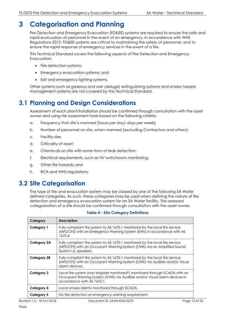
3.2 Site Categorisation
The type of fire and evacuation system may be classed by one of the following SA Water
defined categories. As such, these categories may be used when defining the nature of fire
detection and emergency evacuation system for an SA Water facility. The assessed
categorisation of a site should be confirmed through consultation with the asset owner.
Table 4 - Site Category Definitions
Category Description
Category 1 Fully compliant fire system to AS 1670.1 monitored by the local fire service
(MFS/CFS) with an Emergency Warning System (EWS) in accordance with AS
1670.4.
Category 2A Fully compliant fire system to AS 1670.1 monitored by the local fire service
(MFS/CFS) with an Occupant Warning System (OWS) via an Amplified Sound
System i.e. speakers.
Category 2B Fully compliant fire system to AS 1670.1 monitored by the local fire service
(MFS/CFS) with an Occupant Warning System (OWS) via Audible and/or Visual
alarm devices.
Category 3 Local fire system (non-brigade monitored*) monitored through SCADA with an
Occupant Warning System (OWS) via Audible and/or Visual alarm devices in
accordance with AS 1670.1.
Category 4 Local smoke alarms monitored through SCADA.
Category 5 No fire detection or emergency warning requirement.
TS 0370 Fire Detection and Emergency Evacuation Systems SA Water - Technical Standard
Revision 1.0 - 18 Oct 2018 Document ID: SAWS-ENG-0370 Page 13 of 35
FINAL
* Note: Fire Detection and Alarm systems shall comply fully with this specification and the
requirements of AS1670.1 and the SAMFS conditions of connection to allow for future
connection to the fire service, if this becomes a requirement.
TS 0370 Fire Detection and Emergency Evacuation Systems SA Water - Technical Standard
Revision 1.0 - 18 Oct 2018 Document ID: SAWS-ENG-0370 Page 14 of 35
FINAL
4 Fire Detection and Alarm Systems
4.1 General Requirements
Fire detection and alarm systems shall be independent of any other building/plant monitoring
and control system, with the Control and Indicating Equipment (CIE) contained within its own
enclosure. Alarm and fault signals shall be displayed independently of the plant monitoring
and control (SCADA) system, however, interface of alarm, fault or isolation signals required
under Australian Standards is limited to status monitoring only.
Controls and indicators that form part of any associated systems shall also be contained within
the same CIE enclosure, such as monitoring and control of:
a. Air handling systems (air-conditioning shutdowns);
b. Occupant Warning Systems (To alert occupants of a fire-alarm condition, or for
emergency purposes); and
c. Fire fan controls.
Depending on the Site Category (defined in section 3.2) new fire detection systems to be
installed shall comprise:
1. A Main Fire Indicator Panel (Main FIP) to monitor all aspirated smoke detection systems,
smoke/heat point type detection, other forms of fire detection, manual call points
(MCPs), Sub-Fire Indicator Panels (SFIP), where installed, via a networked system (where
applicable) covering other areas of site.
2. Either of the following:
a. A Master Emergency Control Panel (MECP) or Emergency Warning Control and
Indicating Equipment (EWCIE) to operate speakers located throughout all buildings
where fire detection is provided and various locations outside in plant areas to alert
occupants of either an emergency or automatic fire alarm. Red/Amber strobes shall
be strategically located to give visual indication in areas where ambient sound levels
are too high to hear the evacuation or alert tones clearly. Public Address (PA)
functionality is also to be available for site-wide emergency announcements.
b. An Occupant Warning Control Panel (OWCP) to operate speakers located
throughout all buildings where fire detection is provided, and various locations outside
in plant areas to alert occupants of either an emergency or automatic fire alarm.
Red/Amber strobes shall be strategically located to give visual indication in areas
where ambient sound levels are too high to hear the evacuation or alert tones clearly.
Public Address (PA) functionality is also to be available for site-wide emergency
announcements.
c. Integral sounders, sounder bases or strobe lights driven from the FIP’s addressable loop
or dedicated 24V DC feed, located throughout all buildings where fire detection is
provided and various locations outside in plant areas, to alert occupants of either an
emergency or automatic fire alarm.
Note: For nominated sites (namely, local fire detection systems monitored by SCADA
only), Audible Alarm Devices (AAD) and Visual Alarm Devices (VAD) are to be provided
for occupant warning in lieu of the above.
3. Alarm Signalling Equipment (ASE) located in the Main Fire Indicator Panel that is utilised
to call the fire brigade (where nominated) on the initiation of a fire alarm signal.
The exception to the above are buildings outside the main plant boundary or for nominated
buildings on selective plants where fire detection and warning is to be provided by local
smoke alarms connected to SCADA, as specified.

TS 0370 Fire Detection and Emergency Evacuation Systems SA Water - Technical Standard
Revision 1.0 - 18 Oct 2018 Document ID: SAWS-ENG-0370 Page 15 of 35
FINAL
For fire service appliances to access the site in the event of a fire alarm (or emergency
response) facilities and protocol shall be determined for each site instance through the SA
Water Security Department.
A Main FIP and MECP/EWCIE shall generally be located within the main entry foyer of an SA
Water nominated building on site and must remain clearly visible and readily accessible to the
firefighting service. The only exception is where the site is provided with a fire control room.
Notwithstanding this, the location of the Main FIP and MECP/EWCIE shall comply with the
requirements of the BCA, relevant Australian Standards and in agreement with the relevant fire
authority. Wherever other Fire Indicator Panels are provided on site, they must also be in a
similar location within the building (unless agreed otherwise with the fire service) and shall be
identifiable by red strobe light placed on the outside of the building to assist fire services
locating the designated building entry point.
Contained within each FIP, Zone Block Plans of the installation shall be provided, which contain
the following information:
a. The layout of the building in which the fire system is installed;
b. The area covered by each zone;
c. Detector locations;
d. Fire brigade panel (normally within Main FIP);
e. The location of the FIP, sub-indicator panels (SIP), mimics, data gathering panels and
repeaters; and
f. The location of any other CIE, including any sound systems for emergency purposes.
4.2 Automatic Fire Detection Systems
Building automatic fire detection systems shall be provided at each site in accordance with AS
1670.1, unless nominated for local smoke alarms only. Where required, each system may
include, among other items, any of the following items:
Master Fire Indicator Panel (or Main FIP)
Data Gathering Fire Panels (DGPs)
Sub Fire Indicator Panels (Sub FIP)
Smoke and Heat Detection (to AS 7240.7 and AS 7240.5)
Optical Beam Smoke Detection (to AS 7240.7)
Other forms of fire detection not listed above
Manual call points (MCP)
Remote Indicators for concealed space detection (where not addressable)
Multi-point aspirated smoke detectors (MASD)
Linear Heat Detection (LHD) devices
External Visual Alarm Indicators
Automatic Signalling Equipment (ASE) where nominated for fire bridge monitoring
Interfaces to third party equipment (i.e.) Gas Detection Systems, SCADA, etc.
Building Automatic Air-Handling System shutdown (to AS 1668.1)
Where systems are monitored by the fire bridge they shall comply with the relevant authority
(South Australian Metropolitan or County Fire Service) fire alarm conditions of connection.

TS 0370 Fire Detection and Emergency Evacuation Systems SA Water - Technical Standard
Revision 1.0 - 18 Oct 2018 Document ID: SAWS-ENG-0370 Page 16 of 35
FINAL
4.2.1 Air-Handling System Shutdown
In specially nominated cases, the fire detection system shall provide an appropriate shutdown
signal in the event of a fire to air handling systems, such as air conditioning or exhaust fans, via
interface relays. These relays (where required) shall be installed adjacent to, or inside each
switchboard related to the item to be shut down. Project specifications shall more fully define
these requirements on a case-by-case basis.
Operation of a ‘plant isolate’ function shall inhibit air handling system shutdown. The cabling to
air handling system shutdown relays shall be supervised for ‘open circuit’ condition and shall
raise a fault if disconnected.
4.2.2 Occupant Warning
Where an automatic fire detection system is deemed necessary to be installed at a given site,
at least one of the following shall be provided to alert occupants of a fire alarm situation
depending on the category of system defined in section 3.2, whether manned / unmanned
and other associated risks on site:
a. An Emergency Warning System in accordance with AS 1670.4 (i.e. larger sites); or
b. An Amplified Sound System (single zone OWS) or EWCIE (AS4428.16 Grade 3)
complying with AS1670.1(b) (i.e. medium sized sites); or
c. Audible/Visual Alarm Devices complying with AS 1670.1(b) (i.e. small/unmanned sites).
The operation of an Occupant Warning System (OWS) shall be automatic other than when the
user interface for manual operation is used (in the case of a user-initiated evacuation event
(MCP activation), testing or isolation of equipment).
All distributed and independent fire detection systems (Sub-FIPs) connected to a site’s main FIP
shall, as a minimum, initiate a local building/area evacuation through the
emergency/occupant warning system, but shall also be configurable to activate a site-wide
evacuation, as determined with stakeholders during detailed design.
For consistency of emergency evacuation tones, both the ALERT and EVACUATION signals
generated by any of the above systems and/or audible alarm devices shall be the same
across all sites.
4.2.3 Visual/Audible Alarm Devices
Where Audible Alarm Devices (AAD) and Visual Alarm Devices (VAD) are solely being
provided in lieu of an emergency warning system, an amplified sound system (single zone
OWS) or EWCIE (AS 4428.16 Grade 3), these shall comply with AS ISO 7240.3 and AS ISO 7240.23
respectively.
Audible Alarm Devices provided shall be able to be configurable for staged evacuation
purposes with the functionality to generate both the ‘ALERT’ and ‘EVACUATE’ tones compliant
with AS 1670.14. However, for occupant warning (Fire Alarm) the evacuation signal shall not be
subject to any time delay after an automatic alarm condition has occurred i.e. alert time set to
zero seconds.
Tones generated from AADs shall be synchronized so that signals generated from different
sounders do not merge into one signal and be mistaken for a different alarm.
Visual Alarm Devices shall be provided to reinforce the evacuation signal in areas of high
ambient noise levels and be coloured RED. VADs shall be labelled with the word “EVACUATE”.
Where specified for Audible Alarm Devices (AADs) and/or Visual Alarm Devices (VADs), either
sounders, beacons, sounder beacons and sounder beacon bases for use in conjunction with
both conventional and addressable detectors can be installed, provided they meet the
requirements of AS 1670.1.

TS 0370 Fire Detection and Emergency Evacuation Systems SA Water - Technical Standard
Revision 1.0 - 18 Oct 2018 Document ID: SAWS-ENG-0370 Page 17 of 35
FINAL
4.2.4 Smoke/Heat Alarms
Where specified, local smoke/heat alarms within a building shall be inter-connectable mains-
powered (with either a 10 year rated rechargeable lithium battery or permanently mounted
10 year rated lithium non-rechargeable battery), with one unit fitted with a relay base for a
single “fire alarm” connection to SCADA. Smoke/heat Alarms provided shall comply with the
requirement of AS 3786.
4.2.5 Point-Type Smoke and Heat Detectors
Point-type smoke and heat detectors installed in new installations shall be of addressable type,
unless specified otherwise. When upgrading an existing fire detection system, direction is to be
sought as to the extent of replacement of conventional detectors with addressable type.
Where detection is located within Hazardous Zones, detectors shall be intrinsically safe (I.S.)
and wired through an I.S. Protocol Translator/ Galvanic Barrier installed in a suitable enclosure
located outside the zone (safe area) to ensure system integrity.
Marine Grade detectors (or similar type) shall be provided in environments considered harsh
for standard detectors. (e.g. in locations within 1 km of the ocean or atmospheres subject to
corrosive gases such as Hydrogen Sulfide.)
Remote indicators shall be fitted as required and comply with the requirements of AS 1603.15.
Where existing conventional detectors are being replaced with addressable type, remote
indicators are to be retained where already installed.
4.2.6 Multi-point Aspirated Smoke Detection (MASD)
4.2.6.1 General
Where specified, a MASD based on ‘absolute’ smoke detection technology shall provide
coverage in accordance with the spacing and location requirements of AS 1670.1.
A detailed design of the proposed layout shall be prepared, and approval sought from the
Principal prior to installation. Initial alarm threshold sensitivity and delay settings shall be
determined at design stage, following preliminary system modelling using the detection system
supplier’s proprietary software to confirm system operation.
Final alarm threshold sensitivity and delay settings shall be determined on site, based on the
conditions within the detection area. A minimum of two (2) weeks MASD event history shall be
extracted and viewed to confirm final configurations.
4.2.6.2 Detectors
Detectors shall comply with AS 7240.20 and be modular, with key field replaceable
components such as:
a. Aspirator;
b. Detection Chamber;
c. Filters; and
d. Circuit boards.
Detectors shall incorporate ultrasonic flow monitoring and provide staged airflow faults and
have the capability for in-field smoke chamber cleaning via a purpose-built internal aspirator
to ensure and maintain absolute smoke detection.
4.2.6.3 Sampling Pipe
All sampling pipe shall be smooth bore. Typically, pipe with an outside diameter of 25mm and
internal diameter of 21mm should be used.
TS 0370 Fire Detection and Emergency Evacuation Systems SA Water - Technical Standard
Revision 1.0 - 18 Oct 2018 Document ID: SAWS-ENG-0370 Page 18 of 35
FINAL
The sampling pipe material shall be either PVC, ABS or HFT, and suitable for the environment in
which it is to be installed, or be of the material as required by the Site Schedule.
All joints in the sampling pipe network must be air-tight and glued/secured using solvent
cement suitable for the pipe selected. Pipe entry locations at the detector are not to be
glued.
Pipe marking, including sample points, shall be identified in accordance with the requirements
of AS 1670.1. All pipes should be suitably supported at 1.5m centres.
Expansion joints are to be accommodated within the pipe network where building expansion
and contraction situations exist. Each pipe and branch pipe shall be fitted with an end-cap
(test point) and made air-tight by using appropriate solvent cement installed at an accessible
level, not requiring scissor and/or boom lifts.
The locations of sampling holes shall be determined at the design stage giving consideration to
the environmental conditions and overall system configuration. Intervals may vary per
modelling calculations. The maximum allowable separation distance should not exceed that
as set down in local codes and standards.
Each sample hole shall be sized and countersunk (If required) in accordance with the
manufacturer’s instructions.
Capillary sampling devices shall be used for room space protection at ceiling level where a
main sampling pipe can be concealed above. Ceiling spaces and under-floor voids shall use
standard sampling methods. Capillary tube length is recommended to be a maximum of
500mm per tube. Capillary tube is to be clearly marked “Fire Detection System – Do Not Paint”.
Air conditioning units shall have sampling points installed across the return air grilles. Sampling
points shall be fitted facing downwards to avoid the ingress of dust or debris.
The sensitivity of each sampling point shall be not less than 2.5% obs/m.
Purge Valves shall be fitted to all pipework to allow for sampling points to be cleaned and units
tested for future serving and maintenance.
4.2.7 Linear Heat Detection (LHD)
Where specified, Linear Heat Detection (LHD) cable may be installed where maintenance
access is limited or where environmental conditions limit the use of other detection equipment.
LHD cable chosen shall be listed with Factory Mutual (FM) or Underwriters Laboratories (UL),
temperature-selected to suit ambient conditions. For normal operation, fixed temperature LHD
68 °C shall be used. Concealed spaces and the like shall make use of 88 °C cable.
LHD cable shall be installed in accordance with manufacturer’s recommendations.
LHD cable shall be affixed between 15 and 100 mm from the ceiling or roof structure using the
manufacturer’s recommended fixings. LHD shall be fixed at intervals no more than one metre
apart. Catenary supports and fixings may be provided but care should be taken to ensure the
maximum approved distance to the ceiling is not exceeded.
Connection to the fire detection system shall be via a suitable junction box within the
protected area. When interfacing to an addressable system, a zone input module shall be
used. LHD cable shall be terminated within the protected zone, without passing through other
zones.
A 2 metre test loop shall be provided at the end of the circuit, adjacent the end-of-line
junction box to allow testing in accordance with AS 1851.
4.2.8 Fire Indicator Panels
Fire Indicator Panels shall be of an analogue addressable type, networkable and conform to
AS 7240.2, AS 7240.4 and AS 4428.3 (fire brigade panel), unless specified otherwise. For
networkable systems, local Fire Detecting Control and Indicating Equipment (FDCIE) shall also
be provided on all Sub Fire Indicator Panels in addition to that provided on the Main (Master)

TS 0370 Fire Detection and Emergency Evacuation Systems SA Water - Technical Standard
Revision 1.0 - 18 Oct 2018 Document ID: SAWS-ENG-0370 Page 19 of 35
FINAL
Fire Indicator Panel. Data Gathering Fire Panels used for the purposes of cable junctions only,
are not required to be provided with a FDCIE, and no controls shall be provided at the DGP.
Power Sources for all Fire Indicator Panels shall be as per AS 1670.1 Clause 3.16.
Alarm zone limitations and addressable circuits shall comply with AS 1670.1 Clause 2.3 with any
networked or distributed FDCIE complying with AS 1670.1 Clauses 2.4 and 2.5 respectively. Any
Fire Detection Panel and any detection loops shall be designed with a minimum of 25% spare
capacity.
The Main FIP on site, were required to be monitored by the fire service, shall be directly
connected to either the Metropolitan Fire Service (MFS) or Country Fire Service (CFS) via
automatic Alarm Signalling Equipment (ASE). Existing fire detection system(s) shall be upgraded
to comply fully with all current conditions of connection requirements for the respective fire
service authority.
Regardless if being monitored by the fire service or a local system, the Main Fire Indicator at
each site shall provide the following hardwired output signals to SCADA:
Common fire alarm;
Common fault; and
Common isolation.
In addition to hardwired signals, for larger sites, a High-Level Interface (HLI) shall also provide
the following output signals to SCADA:
Individual fire alarm zone activation;
Individual fire alarm zone fault; and
Individual fire alarm zone isolation.
All fire indicator panels shall be installed within 6 metres of a door entrance, unless otherwise
agreed with the fire service. External alarm indication shall be provided for all FDCIE or DGPs
regardless if containing the fire brigade panel (i.e. Main FIP).
4.3 Emergency Warning Systems
4.3.1 General
An Emergency Warning System (EWS) in accordance with AS 1670.4 shall be a standalone
installation. Control and Indicating Equipment (CIE), however, may be housed within the same
enclosure as the FIP. For an amplified sound system (single zone OWS) or EWCIE (AS1670.16
Grade 3) these can be incorporated as part of Fire Detection Alarm System.
Where required, equipment shall include, but not be limited to the following:
a. Master Emergency Control Panel (MECP);
b. Emergency Warning Control and Indicating Equipment (EWCIE);
c. Secondary Emergency Control Panel (SECP) (where required);
d. Manual Emergency Call Points (ECP);
e. Audible Warning Devices (AWD); and
f. Visual Warning Devices (VWD).
The emergency warning system (EWS) or occupant warning system (OWS) facilitates both
building occupant warning (fire alarm) and site-wide emergency evacuation/public
announcement (PA) purposes. The system shall be capable of generating two different sounds
over loudspeakers. The first tone being the ALERT signal (BEEP BEEP), which is a warning to
people that there is a site-wide emergency (non-fire related), but to stay where they are and
listen to any announcements for further instructions. The second tone being the EVACUATION

TS 0370 Fire Detection and Emergency Evacuation Systems SA Water - Technical Standard
Revision 1.0 - 18 Oct 2018 Document ID: SAWS-ENG-0370 Page 20 of 35
FINAL
signal (WOOP WOOP), which is notification to people to evacuate the area and move to the
designated muster point(s).
Unless otherwise agreed with stakeholders the EWS is to be configured to progress straight to
the EVACUATION tone upon receipt of a Fire Alarm to effect a local building/area evacuation.
For building occupants warning, the EWS or OWS shall be initiated automatically by the fire
alarm system. For other emergency situations and site-wide evacuations the system shall be
capable of being initiated manually (through operator action) or be initiated automatically
through activating a ‘White’ Emergency Call Point (ECP), where provided. The emergency
warning system shall operate continuously during emergency conditions.
Provision of automated pre-recorded voice messaging on the installed warning system shall be
provided to assist occupants in understanding the various fire alarm/emergency warning
tones. It is important to note that SA Water intends on standardising the pre-recorded voice
messages at all of its site assets across the state, to avoid confusion. Consult the Principal if
there is any uncertainty on this aspect.
4.3.2 Emergency Control Panels
Emergency control panel(s) shall be installed in approved locations and shall comply with AS
4428.16 Grade 1 (or AS 2220.1 and AS 60849 until these standards are withdrawn) for AS 1670.4
systems. The MECP shall have full control of all zones across the whole site with CIE also to be
provided for each SECP installed for control of local zones.
For Amplified Sound Systems (single zone OWS) or EWCIE (AS 4428.16 Grade 3) control panels
shall comply with the requirements of AS 1670.1 and be provided with a hand-held
microphone for Public Address (PA) annunciation.
The Main Emergency Control Panel (MECP) or Emergency Warning Control and Indicating
Equipment (EWCIE) shall be integrated into the Main FIP, unless specified otherwise. Equipment
racks may, however, be located remotely from the main operator console, if required.
Secondary Emergency Control Panels (SECPs) shall be provided, where required.
Amplifier(s) shall be provided for each zone and be rated to suit the required load with a
minimum of 30% spare power capacity. Failure of an amplifier or a fault on one line should not
result in the failure of any other amplifier or loudspeaker circuit. Additionally, for AS 1670.4
systems, emergency control panels shall be fitted with 20% spare zone capacity.
For AS 1670.4 systems, the Main Emergency Control Panel (MECP) shall provide the following
output signals to SCADA:
Emergency evacuation system activated;
Manual emergency call point activated;
Emergency evacuation system fault;
Emergency evacuation system isolated; and
Mains power supply failure.
For Amplified Sound Systems (single zone OWS) or EWCIE (AS 4428.16 Grade 3) combined within
the Fire Alarm Control Panel (FACP), the emergency warning system may activate ‘Common’
SCADA signals through the Main FIP instead. Where such equipment is in a standalone cabinet
then separate SCADA signals shall be provided as indicated above for the MECP.
Power to Emergency Control Panels shall be as per AS 1670.4 Section 3 or AS 1670.1 Clause
3.16, where applicable, for the respective system being installed.
4.3.3 Audible Warning Devices
Audible warning devices consist of loudspeakers connected to dedicated amplifiers.
Audible alert and evacuation signals shall comply with AS 1670.4 or AS 1670.1 if used as a
standalone occupant warning system. Other signals types may be more appropriate for use
where the ambient noise may mask the audible signal.

TS 0370 Fire Detection and Emergency Evacuation Systems SA Water - Technical Standard
Revision 1.0 - 18 Oct 2018 Document ID: SAWS-ENG-0370 Page 21 of 35
FINAL
Loudspeakers provided shall be suitable for EWIS (fire and evacuation) installation and those
located in internal situations shall be cone/horn speakers rated IP51 as a minimum, and if
exposed to water or harsh environments, rated not less than IP56. All external loudspeakers shall
be of 12W Weatherproof IP67 rated. Loudspeakers shall be monitored for fault conditions.
Loudspeakers shall be subject to sound pressure level testing to confirm compliance to AS
1670.4 or AS 1670.1 which requires the sound pressure level to be exceeded by a minimum of
10dB the ambient sound pressure level and shall not be less than 65dB and not more than
105dB. Where more than one SPL measurement is required within the evacuation zone, the
difference between the minimum and maximum shall not exceed 15dB.
The exception to the above sound pressure level requirement will be for loudspeakers
indicated for outside areas, where satisfactory levels will be determined via testing, in
conjunction with both the Principal and site stakeholders. Noise generation from audible
alarms must take into consideration any impact on the local community.
The temporal patterns and pre-recorded voice messages output from loudspeakers shall be
synchronized throughout an emergency zone and adjacent area except where the sound
pressure level from an adjacent area is at least 30 dB lower.
4.3.4 Visual Warning Devices
Unless otherwise specified, visual warning devices shall consist of dual amber/red strobe lights
(ideally LED beacons). Visual warning devices shall comply with AS 1603.11.
Internal warning devices shall be rated IP43 as a minimum and if exposed to water or harsh
environments, rated at not less than IP56. All external warning devices shall be rated IP65
(Weatherproof).
Visual warning devices (generally for areas of high ambient noise levels) reinforcing the alert
and evacuate signals shall have a label on or next to the device with the words ALERT and
EVACUATE in letters not less than 25 mm height in a contrasting colour to the background. For
outside visual warning devices, larger signage shall be provided, as appropriate to the site.
4.3.5 Remote Paging Console(s)
Where either an emergency warning system (EWS) or an Amplified Sound System (single zone
OWS) or EWCIE (AS 4428.16 Grade 3) is being provided at any given site, equipment shall have
the functionality for connection of Remote Paging Consoles (RPCs) for the provision of general
PA announcement purposes.
4.3.6 Manual Call Points
SA Water defines ‘break glass’ pushbutton call points as either a:
1. Manual call point (MCP) – interconnected with the Fire Alarm and fire brigade notification
system. (RED in colour); or
2. Manual emergency call point – interconnected with the Emergency Warning System (EWS)
only. (WHITE in colour).
Where Manual Call Points or Manual Emergency Call Points are subject to outdoor or harsh
environments (i.e. H2S gases) they shall be a weatherproof type, of rating at, or above, IP67.
Manual call points are for the initiation of a fire condition and shall be installed in clearly visible
and accessible locations (i.e. building exit points). If not indicated, one shall be provided inside
the main entrance area of each building and may be located on the FDCIE if positioned within
that area.
Manual call points (MCPs) shall be provided which comply with AS 1603.5, coloured RED and
be clearly labelled “FIRE ALARM”.
Manual emergency call points are for local (non-fire brigade call) site-wide emergency
evacuation purposes, generally provided for larger sites in key locations only (i.e. within main
TS 0370 Fire Detection and Emergency Evacuation Systems SA Water - Technical Standard
Revision 1.0 - 18 Oct 2018 Document ID: SAWS-ENG-0370 Page 22 of 35
FINAL
control rooms). Where specified, they shall be interconnected with the emergency evacuation
system (EWS), Amplified Sound System (single zone OWS) or EWIS (AS 4428.16 Grade 3) and
shall indicate the area/zone originating the call and activate the ALERT tone and AMBER
strobe lights, however, they shall not call the MFS/CFS.
Manual emergency call points (ECPs) shall also comply with AS 1603.5 with the exception that
they are coloured WHITE and are clearly labelled “EMERGENCY ALARM”. An engraved multi-
layered Phenolic plastic sheet, such as Gravoply, Rowmark, or approved equivalent label shall
be installed above the unit indicating “LOCAL EMERGENCY ALARM” in black letters not less
than 25 mm height, on a white background.
4.4 Exit and Emergency Lighting
Exit and Emergency lighting shall be installed throughout all buildings locations as specified in
compliance with BCA requirements, AS/NZS 2293.1 and AS/NZS 2293.3.
Upon failure of the electrical supply to the normal lighting in an area, irrespective of whether or
not it is illuminated, each relevant emergency escape luminaire and exit sign shall be
energized from its emergency supply in accordance with AS/NZS 2293.3.
Where new lighting sub-circuits are required to be installed, 90-minute discharge timers with
test facility shall be fitted to distribution switchboards where not currently installed. An
Emergency Test Switch is an emergency test timer (90-minute discharge) as well as a circuit
monitoring device which complies to AS 2293.1:2005 Sensing of supply failure (2.3.3).
Where Exit and Emergency lighting do not have a dedicated sub-circuit, fittings shall be
supplied that comply with AS/NZS 2293.3 clause 4.5. This clause applies to emergency escape
luminaires and exit signs which are provided with self-contained, automatic facilities for
discharge testing (i.e.) fully stand-alone systems.
Where externally located, exposed to water or for any harsh environment, an IP65
weatherproof case shall be fitted to any standard exit lighting or an alternative unit, suitably
rated, is to be sourced. Unless located in an office environment, all internally located
emergency lighting is to be rated IP65, unless indicated otherwise.
All emergency luminaires shall:
1. Be of the self-contained type.
2. Provide a green charge indicator LED (Light Emitting Diode).
3. Provide a status indicator LED which shall provide battery and lamp feedback.
4. Be rated for a ten (10) year design life (including electronics and LED).
5. Incorporate Lithium batteries with a design life of ten (10) years when operated in
accordance with manufacturer's directions and specification.
6. Be tested to comply with a mutually recognised testing laboratory to the relevant scope
of AS CISPR 15, AS/NZS 60598.2.22 and AS/NZS IEC 61347.2.13.
All exit luminaires shall:
1. Be of the self-contained type.
2. Provide a green charge indicator LED (Light Emitting Diode).
3. Provide a status indicator LED which shall provide battery and lamp feedback.
4. The emergency exit sign (pictorial ‘running man’ type) shall be designed for a ten (10)
year design life, including the electronics and LEDs.
5. Incorporate Lithium batteries with a design life of ten (10) years when operated in
accordance with manufacturer's directions and specification.

TS 0370 Fire Detection and Emergency Evacuation Systems SA Water - Technical Standard
Revision 1.0 - 18 Oct 2018 Document ID: SAWS-ENG-0370 Page 23 of 35
FINAL
6. Incorporate a soft-start charger function.
7. Be the permanently maintained type, utilising LEDs with expected lifetime of 100,000
hours to L70/B50.
8. Incorporate green and white pictograph and directional arrows, as required (or green
letters on black background when used in areas of low illumination).
9. Be tested to comply with a mutually recognised testing laboratory to the relevant scope
of AS CISPR 15, AS/NZS 60598.2.22 and AS/NZS IEC 61347.2.13.
Battery Specific Requirements:
1. Batteries for single point emergency luminaries shall be of a Lithium ion Phosphate type
with a maximum cell temperature not less than 60 °C.
2. The design life of the batteries and their application in the emergency and exit luminaire
shall be designed for ten (10) years at a cell temperature of 45°C.
3. Battery packs must incorporate battery protection (for over voltage in charge, low
voltage protection and over current in discharge) and shall be labelled with date of
manufacture, amp hour (Ah) rating and replacement part number.
4.5 Exit Doors
All exit doors relating to the intended emergency exit paths from a facility shall be designed (or
if existing, modified/altered) such that they are in accordance with the Building Code of
Australia, or if not practical, a performance solution be provided by a qualified fire engineer
that demonstrates compliance with the relevant performance requirements. All doorhandle
hardware requiring locking is to be fitted with new barrels supplied from an SA Water
nominated locksmith. Key type shall be determined with site stakeholders.
4.6 Gas Detection Systems
Where specified by the Site Schedule, fire/emergency warning systems shall provide a
connection point to existing site Gas Detection Systems (i.e. Chlorine, Oxygen, Methane and
H2S alarm systems), where provided. As a minimum, a single alarm output shall be provided
from the Gas Detection System to activate the EWS warning signal ‘ALERT’ tone and ‘AMBER’
strobe lights within the affected area of the plant. The fire system shall NOT be configured to
call the Metropolitan Fire Service (MFS) or Country Fire Service (CFS), but act as a local alarm
indication only.
Subject to a risk assessment, additional trigger levels (i.e. high-level gas leak) shall also be
provided from the Gas Detection System to escalate the EWS to a site-wide evacuation
(‘EVACUATION’ tone and ‘RED’ strobe lights), and, if required, send a primary alarm (separate
indication to Fire) through the ASE for emergency service attendance (i.e. HAZMAT).
4.7 SCADA
As a minimum, output signals shall be hardwired from the Main Fire Indicator Panel and the
Main Emergency Control Panel (MECP) to the plant PLC and/or RTU, for integration of alarms to
SCADA.
For larger sites ‘Individual Zone Indication’ is also required, and these signals may be obtained
via providing a High-Level Interface (HLI) from the site Main Fire Indicator Panel (or from a Data
Gathering Panel, if system is networked). Critical ‘Common Alarm’ signals, however, must be
hardwired for redundancy. Where there are Main and Sub panel HLIs, and hardwired signals,
logic must be implemented to avoid multiple alarms in SCADA for the one zone fault.
The recommended HLI communication is Modbus (either serial or TCP/IP) via a suitable
Protocol Converter fitted between both PLC/SCADA and FIP. The preference for the protocol
converter is for it to be mounted in the FIP.

TS 0370 Fire Detection and Emergency Evacuation Systems SA Water - Technical Standard
Revision 1.0 - 18 Oct 2018 Document ID: SAWS-ENG-0370 Page 24 of 35
FINAL
The SCADA System modifications shall comply with the latest SA Water SCADA System
Technical Standards and manuals, and be undertaken by an authorised SA Water Systems
Integrator.
Figure 4-1 – Control System Boundaries
No control shall be directed through SCADA. Functionality shall only be conducted through the
CIE of both the Fire Detection and Emergency Warning Systems. Fire alarms are, however, to
escalate through the existing SCADA network. Screen(s) shall be configured, where required,
to display the following information:
1. Fire/Emergency Warning System Overview
General system status for both the Fire Alarm System and Emergency Warning System. For
larger sites, a visual site overview of the plant showing each building alarm state (RED - Fire /
GREY – Normal) shall be displayed. Consideration should be given to replicating Block Plans on
SCADA screens to maintain consistency throughout the entire SA Water SCADA system.
2. Fire System Zone Status
For larger sites, a detailed status of each fire zone from the FIP indicating if it is in ALARM, FAULT
or has been ISOLATED, shall be displayed.
As a general rule:
a. Indications should always open a tag popup BDF and/or perform navigation to an
alarms display page, in a similar fashion to other SCADA device indications like pumps
as an example.
b. SCADA tags should have an defined syntax, and descriptions.
c. The links to the fire/evacuation system pages should be located on the individual
plant main menu page.
PLC/RTU RS485 Serial
Protocol
Interface
Fire/Emergency
Warning System SCADA
Hardwired I/O

TS 0370 Fire Detection and Emergency Evacuation Systems SA Water - Technical Standard
Revision 1.0 - 18 Oct 2018 Document ID: SAWS-ENG-0370 Page 25 of 35
FINAL
5 Fire Detection and Emergency Warning System
Installation The construction and installation of fire detection systems and sound and intercom systems
shall comply with the requirements of TS 0300, SAMFS Policy 037, AS/NZS 3000, AS/NZS 3013, AS
1670.1 and AS 1670.4 and the following additional requirements.
Minimum qualifications of installation contractors should be as follows:
Cabling licence
Registered with SAMFS as competent fire safety technician
Ideal qualifications are as follows:
FPA registration number
NFIA registration number
5.1 Cabling
All network cabling shall have a rating of WS52XW (fire rated 120min and resistance to water)
with mechanical protection in accordance with and AS 1670.1-Appendix B and AS 1670.4-
Appendix C. Mechanical rating to be upgraded dependent upon the hazard, as defined in
AS/NZS 3013, and additionally, if exposed to damage from vermin (namely within underground
conduits and pits) cabling shall be steel wired armoured for protection.
Customer cabling, including extra-low voltage power supply wiring of the fire detection and
alarm system, shall be kept separate and distinct from all other systems and shall be in
accordance with the requirements of AS/CA S009.
The wiring of amplified sound systems is deemed to be ‘customer cabling’ and shall meet the
requirements of AS/CA S009 and requires separation from either low voltage (LV) or extra-low
voltage (ELV) circuits, depending on their operating voltage, in accordance with this standard
and AS 1670.1.
5.2 Electrical Installation for Hazardous Areas
Electrical equipment installed in Hazardous Areas shall be appropriately rated for the area in
which they are installed and the protection technique of the associated equipment.
Installations shall comply with the requirements of AS/NZS 60079.14 Explosive atmospheres -
Electrical installations design, selection and erection and TS 0300.
5.3 Labelling and Marking
All detectors shall be marked with permanent labels indicating Alarm Zone (or Circuit/Zone
number), device number and type of detector for each installed device. Labels shall be of the
printed type. An example being:
AZ1 - L2 - 004P - Alarm zone one, loop two, device four and photo optical smoke detector.
Note: Identification on the detector is to be consistent with the information displayed at the FIP.
The Block Plan legend and the device number shall read the same as the display on the FIP.
All break glass units shall be labelled with zone, loop and address number on permanently
printed labels.
Loop powered strobes shall be labelled as appropriate. Supply air detectors shall be provided
with permanent engraved labels stating the zone in addition to the loop and address detail.
All air handling shutdown and interface relays shall be labelled accordingly. Where provided
inside mechanical services switchboards, relays shall be labelled within and on the cabinet
door stating: ‘Fire Alarm Relay within’.
TS 0370 Fire Detection and Emergency Evacuation Systems SA Water - Technical Standard
Revision 1.0 - 18 Oct 2018 Document ID: SAWS-ENG-0370 Page 26 of 35
FINAL
All 230 V AC supplies and labelling shall comply with AS/NZS 3000 and be marked accordingly
so that they are easily distinguished from ELV circuits. The 230 V supply breaker at the main
switchboard shall be marked with a permanently engraved label stating: ‘FIRE ALARM’ in text
10 mm high (minimum). An origin of supply label shall be fitted to the fire panel.
Cable labelling for fire system components shall be as per AS1670 standards. Any cables
interfacing from external systems to fire systems shall follow the conventions of TS 0300.
5.4 Documentation
5.4.1 Coloured Zone Block Plan
A zone block plan is required to be provided as per AS 1670.1. The block plan is required to be
A3 or A4 sized, as appropriate.
The plan is to identify each zone protected via individual shades of colours that are not similar
to adjacent colours. The main fire indicator panel, sub-indicator panels, mimics and repeater
panels are to be shown on the plan. The plan is also to show any warning systems and
intercom systems. Refer to 5.6Appendix A for an example of what is expected.
The block plan shall be clearly legible without the need to ‘interpret’ the information within and
should display room names or areas to clearly identify where the alarm is located.
The block plan is to be displayed in the correct orientation of the building from the point it is
being viewed.
Emergency telephone numbers shall be included on the plan.
For more detail on the requirements of Block Plans, refer to SAMFS Policy 037.
All main switchboard locations shall be shown.
A3 or A4 sub-plans shall be supplied at FIPs, with details including detector location, address
and zone information.
Any proprietary drawings supplied must either be converted onto an SA Water drawing
template or, if not available in CAD format, be mapped onto an SA Water drawing template
to allow an assigned drawing number to be referenced in the SA Water drawing systems.
5.4.2 Fire Indicator Panel Configuration Data
A copy of any software configuration files shall be included in electronic format within each
Operator Handbook/Maintenance Manual. An additional copy of the software shall be
provided for storage by the Principal.
A scanned copy of all device tests shall be obtained from the site monitoring system and shall
be included in final commissioning documents. This shall show all devices tested and necessary
commissioning tests, as required by AS 1670 series standards.
5.4.3 Log Books
Log books shall be supplied with all new systems. These shall meet with the requirements stated
in AS 1851.
5.5 Testing and Commissioning
The Contractor shall test and commission all systems and equipment in accordance with the
requirements of the applicable Australian Standards to ensure correct operation. Further
testing shall be carried out where required by official bodies having jurisdiction. Note that all
detectors, sampling points, speakers, devices, inputs, outputs, relays and hardware shall be
fully tested.
The following data and compliance certifications should be provided, as a minimum, at the
completion of commissioning:

TS 0370 Fire Detection and Emergency Evacuation Systems SA Water - Technical Standard
Revision 1.0 - 18 Oct 2018 Document ID: SAWS-ENG-0370 Page 27 of 35
FINAL
Commissioning results of sound pressure level testing;
Certification that the cabling complies with AS/CA S009;
Completed AS1670.1 Appendix E; and
Form 2 associated with the installation.
5.6 Operator Training
Every new FD&EE system installed shall be accompanied with sufficient operator training for
nominated SA Water specified representatives.
Training courses shall be of suitable duration for explanation and understanding of the installed
systems and are to be conducted within one week of the system being commissioned when it
is in full operation.
The training shall include Operator Handbooks to all trainees, per TS 0132, detailing all essential
information, including all necessary drawings, charts, notes and support information.

TS 0370 Fire Detection and Emergency Evacuation Systems SA Water - Technical Standard
Revision 1.0 - 18 Oct 2018 Document ID: SAWS-ENG-0370 Page 28 of 35
FINAL
Appendix A – Coloured Zone Block Plan Examples
The following figures in this appendix provide an example of what is expected in a Block Plan.
Figure 5-1 - Block Plan Example (1 of 9)

TS 0370 Fire Detection and Emergency Evacuation Systems SA Water - Technical Standard
Revision 1.0 - 18 Oct 2018 Document ID: SAWS-ENG-0370 Page 29 of 35
FINAL
Figure 5-2 - Block Plan Example (2 of 9)
Figure 5-3 - Block Plan Example (3 of 9)

TS 0370 Fire Detection and Emergency Evacuation Systems SA Water - Technical Standard
Revision 1.0 - 18 Oct 2018 Document ID: SAWS-ENG-0370 Page 30 of 35
FINAL
Figure 5-4 - Block Plan Example (4 of 9)
Figure 5-5 - Block Plan Example (5 of 9)

TS 0370 Fire Detection and Emergency Evacuation Systems SA Water - Technical Standard
Revision 1.0 - 18 Oct 2018 Document ID: SAWS-ENG-0370 Page 31 of 35
FINAL
Figure 5-6 - Block Plan Example (6 of 9)
Figure 5-7 - Block Plan Example (7 of 9)

TS 0370 Fire Detection and Emergency Evacuation Systems SA Water - Technical Standard
Revision 1.0 - 18 Oct 2018 Document ID: SAWS-ENG-0370 Page 32 of 35
FINAL
Figure 5-8 - Block Plan Example (8 of 9)
Figure 5-9 - Block Plan Example (9 of 9)

TS 0370 Fire Detection and Emergency Evacuation Systems SA Water - Technical Standard
Revision 1.0 - 18 Oct 2018 Document ID: SAWS-ENG-0370 Page 33 of 35
FINAL
Appendix B – Fire and Evacuation Drawing Examples The following figures in this appendix provide a sample of what might be expected for Fire
Detection and Emergency Evacuation Electrical Drawings.
Figure 5-10 - Site Plan Example
Figure 5-11 – Legend and Symbols Example

TS 0370 Fire Detection and Emergency Evacuation Systems SA Water - Technical Standard
Revision 1.0 - 18 Oct 2018 Document ID: SAWS-ENG-0370 Page 34 of 35
FINAL
Figure 5-12 – Specific Location Arrangement Example
Figure 5-13 – External Speaker and Strobe Light Locations and Coverage Example

TS 0370 Fire Detection and Emergency Evacuation Systems SA Water - Technical Standard
Revision 1.0 - 18 Oct 2018 Document ID: SAWS-ENG-0370 Page 35 of 35
FINAL
Figure 5-14 – Network Block Diagram Example
Figure 5-15 – Cabling Routes Example
Top Related