


Languages
Pages
Legal


Triax Multiswitches
TRIAX - your ultimate connection

We’ve got multiswitches for all your needs. Now let’s help you pick the right one.
What exactly do you need a multiswitch for? From a technical point of view, it enables many set-top box users to share a single dish/LNB installation and cabling.
All users will enjoy a full digital signal quality- from satellite to set-top box. And from an aesthetical and practical point of view,multi switches can help you avoid many dishes on a building.
In addition, you get the following features with set-top box and multiswitch installations: Full DVD-picture quality, full DVD/CD-sound quality, real 16:9 picture format, high definition capability and surround sound.
When should you use a multiswitch? • Whenever more than four users have their own individual set-top box – and need a shared dish.
• When many channels are required. • When users live within a relatively short distance of the dish – and each other.
The number of satellite positions and polarities, along with user/subscriber outputs, determine the right choice of multiswitch for you.
People often ask us if it’s possible to receive signals from more than one satellite position. The answer is yes. Solutions exist for one to four individual satellite positions. If you want more than one position, please look for the multiswitch solutions that include a DiSEqC-switch.
Another frequently asked question concerns the distribution of different signals. Can terrestrial and cable signals be distributed via a multiswitch that already provides satellite signals? Yes they can. Most of the time, both co-exist on the same cable.
If you need to expand or change an installation in the future, you can generally apply new products to existing systems – saving you both time and money. And despite their advanced and complex technical qualities, all Triax products are designed to be easy to install and use.

TMM Cascade Multiswitches
Integrated Reception Systems (IRS) with the TMM 5 input and TMM 9 input series of cascadable multiswitches
Fully modular and cascadable, the TMM 5 and 9 input series can be used for systems with 1 or 2 satellite positions plus terrestrial. Both series are compact and simple to install.
This series is your preferred choice when you want to:
• Install a cascade system for one or two satellite positions plus terrestrial• Balance signal levels throughout a system• Expand your system at a later date• Power from anywhere on the system• Power from a remote location
Key Features
• Multiswitch satellite functions powered from satellite receiver• Multiswitch terrestrial amplifier powered from terrestrial trunk cable• Level adjustment for each input• External power supply for powering headend amplifiers, distribution amplifiers, LNB(s) and multiswitch terrestrial amplifiers
• Power from anywhere on the system, simply inject the DC into an amplifier or use the TMM power inserter• Wall or plate mountable - allows assembly on or off site• Colour coded connectors throughout range• Supplied with output earth bond bars• Full range of accessories available

PART NO 305393 305394 305395 305396 305397
FREQUENCY RANGE (MHz) 47-2150 47-2150 47-2150 47-2150 47-2150
INPUTS 4 SAT + 1 TERR 4 SAT + 1 TERR 4 SAT + 1 TERR 4 SAT + 1 TERR 4 SAT + 1 TERR
THROUGH OUTPUTS 4 SAT + 1 TERR 4 SAT + 1 TERR 4 SAT + 1 TERR 4 SAT + 1 TERR
MULTISWITCH OUTPUTS 4 8 12 16 12
CONNECTORS F-TYPE F-TYPE F-TYPE F-TYPE F-TYPE
TRUNK LOSS (dB) TERR 47-862 MHz 1.5 2.5 3 3
SAT 950-2150 MHz 1.5 2.5 2.5 2.5
TAP LOSS (dB) TERR 47-862 MHz 10 10 12 12 0
SAT 950-2150 MHz 10 10 12 12 0
LEVEL ADJUST RANGE (dB) TERR 47-862 MHz 0-12
SAT 950-2150 MHz 0-12
ISOLATION (dB) TERR TO SAT dB 35 35 30 30 30
SAT TO TERR dB 35 35 30 30 30
CROSS POLAR H/V dB 30 30 28 28 28
OUT-OUT TERR dB 30 30 30 30 30
OUT-OUT SAT dB 30 30 30 30 30
RETURN LOSS (dB) TERR INPUT 47- 862 MHz 12 12 12 12 12
TERR OUTPUT 47-862 MHz 12 12 12 12
SAT INPUT 950-2150 MHz 12 12 12 12 12
SAT OUTPUT 950-2150 MHz 12 12 12 12
MULTISWITCH OUTPUT47-862 MHz
10 10 10 10 12
MULTISWITCH OUTPUT950-2150 MHz
10 10 10 10 12
OUTPUT LEVEL (dBuV) SAT (IMA3, 35dB) EN50083-3 95 95 95 95 95
TERR (IMA3, 60dB) EN50083-5 88 85 85 85 85
INPUT LEVEL (dBuV) SAT (IMA3, 35dB) EN50083-3 117 117 119 119 112
TERR (IMA3, 60dB) EN50083-5 110 107 109 109 102
SWITCHING COMMANDS 13V,18V, 13V/22kHz, 18V/22kHz
SWITCHING VOLTAGE 15+/- 1V
TERRESTRIAL CURRENT (mA) -(SUPPLIED FROM TERRESTRIAL TRUNK LINE)
50 95
MAX CURRENT OF EACH OUT PORT(SUPPLIED BY SATELLITE RECEIVER)
<200mA <250mA
• 5 Inputs, 5 Through Outputs• 4, 8, 12, 16 and 12T Multiswitch Output versions• Level controls on all Inputs
• Built in Amplification• Terrestrial Amplifiers powered via Trunk Line• Colour coded Trunk Connections• Supplied with Output Earth Bonding Bars
TYPE TMM 5x4 TMM 5x8 TMM 5x12 TMM 5x16 TMM 5x12T
Triax TMM 5 Series

PART NO 305294 305295 305296
FREQUENCY RANGE (MHz) 47-2150 47-2150 47-2150
INPUTS 8 SAT + 1 TERR 8 SAT + 1 TERR 8 SAT + 1 TERR
THROUGH OUTPUTS 8 SAT + 1 TERR 8 SAT + 1 TERR 8 SAT + 1 TERR
MULTISWITCH OUTPUTS 8 12 16
CONNECTORS F-TYPE F-TYPE F-TYPE
TRUNK LOSS (dB) TERR 47-862 MHz 2.5 3 3
SAT 950-2150 MHz 2.5 3.5 3.5
TAP LOSS (dB) TERR 47-862 MHz 12 14 14
SAT 950-2150 MHz 12 14 14
LEVEL ADJUST RANGE (dB) TERR 47-862 MHz 12
SAT 950-2150 MHz 12
ISOLATION (dB) TERR TO SAT dB 30 30 30
SAT TO TERR dB 30 30 30
CROSS POLAR H/V dB 30 28 28
OUT-OUT TERR dB 30 30 30
OUT-OUT SAT dB 30 30 30
RETURN LOSS (dB) TERR INPUT 47- 862 MHz 12 12 12
TERR OUTPUT 47-862 MHz 12 12 12
SAT INPUT 950-2150 MHz 12 12 12
SAT OUTPUT 950-2150 MHz 12 12 12
MULTISWITCH OUTPUT47-862 MHz
10 10 10
MULTISWITCH OUTPUT950-2150 MHz
10 10 10
OUTPUT LEVEL (dBuV) SAT (IMA3, 35dB) EN50083-3 95 95 95
TERR (IMA3, 60dB) EN50083-5 85 85 85
INPUT LEVEL (dBuV) SAT (IMA3, 35dB) EN50083-3 119 121 121
TERR (IMA3, 60dB) EN50083-5 109 111 111
SWITCHING COMMANDS 13V,18V, 13V/22kHz, 18V/22kHz, DiSEqC 2.0
SWITCHING VOLTAGE 15+/- 1V
TERRESTRIAL CURRENT (mA) -(SUPPLIED FROM TERRESTRIAL TRUNK LINE)
50 95
MAX CURRENT OF EACH OUT PORT(SUPPLIED BY SATELLITE RECEIVER)
<200mA <250mA
TYPE TMM 9x8 TMM 9x12 TMM 9x16
Triax TMM 9 Series
• 9 Inputs, 9 Through Outputs• 8, 12 and 16 Multiswitch Output versions• Level controls on all Inputs• Built in amplification• Terrestrial Amplifiers powered via Trunk Line• Colour coded Trunk Connections• Supplied with Output Earth Bonding Bars

Triax TMM Amplifiers
PART NUMBER 305335 305305 305306 305315
FREQUENCY RANGE (MHz) 47 - 2150 950 - 2150 47 - 862 47 - 862
INPUTS 4 SAT / 1 TERR 4 SAT 11 X B1/FM : 1 X BIII/DAB :
UHF 1 : UHF 2
OUTPUTS 4 SAT / 1 TERR 4 SAT 1 1
GAIN(dB)
TERR W/B (47-862 MHz) 17 30
TERR BI /FM (47 -108 MHz) 40
TERR BIII/DAB (174-230 MHz) 40
TERR UHF 1 (470-862 MHz) 40
TERR UHF 2 (470-862 MHz) 40
SAT 950-2150 25 40
GAIN CONTROL (dB)
TERR W/B (47-862 MHz) 20 0 - 20
TERR BI /FM (47 -108 MHz) 0 - 20
TERR BIII/DAB (174-230 MHz) 0 - 20
TERR UHF 1 (470-862 MHz) 0 - 20
TERR UHF 2 (470-862 MHz) 0 - 20
SAT 950-2150 20 0 - 20
SLOPE CONTROL (dB)
TERR W/B (47-862 MHz) 2 -15 0 - 18
TERR BI /FM (47 -108 MHz)
TERR BIII/DAB (174-230 MHz)
TERR UHF 1 (470-862 MHz) 0 - 10
TERR UHF 2 (470-862 MHz) 0 - 10
SAT 950-2150 0 - 5 0 - 10
OUTPUT LEVEL (dBuV)
SAT (IMA3, 35dB) EN50083-3 110 115
TERR (IMA3, 60dB) EN50083-5
W/B (47-862 MHz) 105 118
BI /FM (47 -108 MHz) 118
BIII/DAB (174-230 MHz) 118
UHF 1 (470-862 MHz) 115
UHF 2 9470-862 MHz) 115
ISOLATION (dB) TRUNK - TRUNK 32 35
RETURN LOSS (dB)
TERR W/B (47-862 MHz) 10 10
TERR BI /FM (47 -108 MHz) 10
TERR BIII/DAB (174-230 MHz) 10
TERR UHF 1 (470-862 MHz) 10
TERR UHF 2 (470-862 MHz) 10
TERR OUTPUTS 47 - 862 10 10 10
SAT INPUTS 950 - 2150 10 10
SAT OUTPUTS 950 - 2150 10 10
LNB POWER SUPPLY 2 X 14VDC / 2 X 18VDC,
400mA MAX 2 X 14VDC / 2 X 18VDC,
400mA MAX
EXTERNAL SWITCH MODE POWER SUPPLY 18VDC IN VIA 3.5mm DC JACK 18VDC IN VIA 3.5mm DC JACK 18VDC IN VIA 3.5mm DC JACK 18VDC IN VIA 3.5mm DC JACK
LINE POWER SUPPLY VOLTAGE H: 18V+/-0.5V, V: 13V+/-0.5V H: 18V+/-0.5V, V: 13V+/-0.5V
TERRESTRIAL THROUGH VOLTAGE / CURRENT 12VDC +/-0.5V, 1.5A MAX 12VDC +/-0.5V, 1.5A MAX 12VDC +/-0.5V, 1.5A MAX
POWER CONSUMPTION (mA) 350 390 200 320
CONNECTOR TYPE ‘F’ (FEMALE) ‘F’ (FEMALE) ‘F’ (FEMALE) ‘F’ (FEMALE)
LINE POWERING VIA INPUT OR OUTPUT VIA INPUT OR OUTPUT VIA INPUT OR OUTPUT VIA OUTPUT
DC SWITCH (FOR USE WHEN INJECTING DC)SWITCHABLE - UP / DOWN /
UP+DOWN
UHF 1 MASTHEAD POWER SUPPLY (VDC) 12 +/-0.5 (SWITCHABLE)
TYPE TMM 55AMP TMM 44AMP TMM TDATERR DISTRIBUTION AMP
TMM TLATERR LAUNCH AMP
TMM 44 AMP
• 4 x Satellite Amplifiers• High Gain / Output• Gain and slope control on all inputs• Line powered or powered from external power supply• Power on LED’s• Colour coded inputs and outputs
TMM Terrestrial Distribution Amplifier (TDA)
• Single Wideband Input, single Output• High Gain and Output• Gain and Slope controls • Line powered via Input or Output or powered from external power supply• Directional DC switch, (Power Up, Power Down or Power Up+Down)
TMM 55 AMP
• 4 x Satellite Amplifiers plus 1 x Terrestrial Amplifier• Gain and slope control on all inputs• Line powered or powered from external power supply• Power on LED’s• Colour coded inputs and outputs
TMM Terrestrial Launch Amplifier (TLA)
• Splitband Inputs, single output• Band I/II (FM), Band III/DAB plus two UHF Inputs.• High Gain• Gain control on all inputs, Slope controls on UHF Inputs • Line powered via Output or powered from external power supply• Switchable Masthead Amplifier supply on UHF 1 Input

PART NUMBER 305319 305320 305321 305313
FREQUENCY RANGE (MHz) 47 - 2150 47 - 2150 47 - 2150 47 - 2150
INPUTS 4 SAT / 1 TERR 4 SAT / 1 TERR 4 SAT / 1 TERR 4 SAT / 1 TERR
OUTPUTS 8 SAT / 2 TERR 8 SAT / 2 TERR 16 SAT / 4 TERR 16 SAT / 4 TERR
INSERTION LOSS IN-OUT (dB) TERR 47 - 862 4.3 4.3 8.0 8.0
SAT 950 - 2150 4.5 4.5 8.5 8.5
ISOLATION OUT-OUT (dB) TERR 47 - 862 22 22 24 24
SAT 950 - 2150 20 20 22 22
RETURN LOSS (dB) TERR INPUT 47 - 862 15 15 15 15
SAT INPUT 950 - 2150 13 13 13 13
TERR OUTPUT 47 - 862 15 15 15 15
SAT OUTPUT 950 - 2150 13 13 13 13
CONNECTORS ‘F’ (FEMALE) ‘F’ (FEMALE) ‘F’ (FEMALE) ‘F’ (FEMALE)
TYPE TMM 5 SPLIT TMM 4+1 SPLIT TMM 5/20 SPLIT TMM 4+1/20 SPLIT
TMM 5 SPLIT
• 5 Inputs, 10 Outputs• 4 x Satellite Inputs plus 1 x Terrestrial Input• 5 In - line inputs• Power Pass all ports• Colour coded connectors
TMM 4+1 SPLIT
• 5 Inputs, 10 Outputs• 4 x Satellite Inputs plus 1 x Terrestrial Input• 4 In - line Satellite inputs plus 1 offset Terrestrial Input• Power Pass all ports• Colour coded connectors
TMM 5/20 SPLIT
• 5 Inputs, 20 Outputs• 4 x Satellite Inputs plus 1 x Terrestrial Input• 5 In - line inputs• Power Pass all ports• Colour coded connectors
TMM 4+1/20 SPLIT
• 5 Inputs, 20 Outputs• 4 x Satellite Inputs plus 1 x Terrestrial Input• 4 In - line Satellite inputs plus 1 offset Terrestrial Input• Power Pass all ports• Colour coded connectors
Triax TMM Splits

TMM input earth bond bar
IRS Miscellaneous
TMM PSI
• DC Power Inserter• 5 Inputs, 5 Outputs, (4 x Satellite plus 1 x Terrestrial)• DC switch on Terrestrial Leg to select direction of power• ‘Power On’ LED on each trunk line• Colour coded connectors
TMM PSU• External Switch Mode Power Supply• Rack Mounted• DC Output fly lead
Part No. 305310
Model TMM PSU
Input Voltage (Vac) 180-250
Input Frequency Range (Hz) 47-63
Output Voltage (VDC) 18
Output Current (A) 1.9
DC Output Fly Lead with 3.5mm Plug
Part No. Product Description
305344 For 4 Input TMM Modules
305345 For 5 Input TMM Modules
305343 For 9 Input TMM Modules
Part No. Model Product Description
305301 TMM 4P Mounting Plate - 4 Modules
305302 TMM 6P Mounting Plate - 6 Modules
305304 TMM MPC Mounting Plate Coupler (2 per Pack)
305307 TMM DCL DC Link Lead
305309 TMM Connecting Lead KitKit of 5 Colour Coded Leads for connecting TMM Modules
305350 TMM Remote Power LeadAllows a TMM System to be powered via a Coax Cable from a remote TMM PSU(Kit of 2 F to DC Adapter Leads)
370009 TMM F CouplerQuick Fit F Male to F Male Connector(5 per Bag)
305349 TMM TermF Type (Male), DC Blocked, 75ohm,Terminator (5 per Bag)
Part No. Model Product Description
300313 TMS 55 Tap 12.5dB5 In, 5 Through Output, 5 tap Outputs, 12.5dB Tap Loss
300333 TMS 55 Tap 15dB5 In, 5 Through Output, 5 tap Outputs, 15dB Tap Loss
300343 TMS 55 Tap 20dB5 In, 5 Through Output, 5 tap Outputs, 20dB Tap Loss
300353 TMS 55 Tap 24dB5 In, 5 Through Output, 5 tap Outputs, 24dB Tap Loss
300319 TMS 510 Splitter 5 Input, 10 Output Splitter
370652 In-line Terrestrial AmplifierIn-line Terrestrial Amplifier, 47-862 MHz, 15dB Gain
300401 In-line Terr/Satellite AmplifierIn-line Amplifier, 47-2300 MHz, 16-20dB Gain
370650 In-line Satellite Slope AmplifierIn-line Satellite Amplifier, 950-2150 MHz, 2-12dB Gain, 0-10dB Slope
370651 In-line Satellite IF High Pass FilterIn-line Satellite IF High Pass Filter, 950-2150 MHz
370706 In-line DC block 47-2150 MHz DC Block
Triax TMM Cascade Multiswitches
Accessories
Part No. 305311
Model TMM PSI
No. Inputs 5-(4xSat+1xTerr)
No. Outputs 5-(4xSat+1xTerr)
Frequency Range (MHz) 47-2150
Insertion Loss• TERR (dB)• SAT (dB)
1.52.5
Power Input 18VDC via 3.5mm DC Jack
Terrestrial Supply Up/Down/Up+Down(Switchable)
Dimensions (mm) 181x162x35.4

Integrated reception systems (IRS) with the TMP 5 and TMP 9 input series.
These are mains powered, stand alone multiswitches for one or two satellite positions plus terrestrial. Both series are compact and easy to install.
This series is your preferred choice when youwant to:
• Supply many users with consistent output levels
• Use the same switch, no matter how close or far away you are from the headend
Key Features
• Wide range of 8, 12, 16, 24 and 32 output multiswitches
• Watch terrestrial signals without using a set-top box
• Adjustable outputs to compensate for long cables and distances (24 and 32 output versions)
• Adjustable inputs
• Built-in switch mode power supply
• Colour coded inputs
• Supplied with input and output earth bond bars
Individualattenuators on each input
L-M-S switches(0-6-12 dB) for long,medium and shortsubscriber lines in banks of 4 outputs
TMP 5x and 9x series comprise versions with 8 to 32 subscriber outputs
Triax TMP Multiswitches

TRIAX TMP RANGE - 5 INPUT TMP 5 x 8 TMP 5 x 12 TMP 5 x 16 TMP 5 x 24 TMP 5 x 32
Part Number 305370 305372 305374 305376 305378
Frequency Range (MHz) Terrestrial 47 - 862 47 - 862 47 - 862 47 - 862 47 - 862
Satellite 950 - 2150 950 - 2150 950 - 2150 950 - 2150 950 - 2150
Inputs 5 5 5 5 5
Outputs 8 12 16 24 32
Insertion Loss (dB) Terrestrial 0 0 0 0 0
Satellite 0 0 0 0 0
Input Level Control (dB) Terrestrial 15 15 15 15 15
Satellite 10 10 10 10 10
Slope Control (dB) Terrestrial 10 10 10 10 10
Output Level Control (dB) Long Cable / / / 0 0
Medium Cable / / / 6 6
Short Cable / / / 12 12
Isolation (dB) Horiz / Vert 30 30 30 30 30
Terr - Sat 30 30 30 30 30
Sat -Terr 30 30 30 30 30
Out / Out - Terrestrial 30 30 30 30 30
Out / Out - Satellite 30 30 30 30 30
Input Return Loss (dB) Terrestrial 10 10 10 10 12
Satellite 10 10 10 10 12
Output Return Loss (dB) Terrestrial 8 8 8 8 10
Satellite 8 8 8 8 10
Max. Output Level (dBuV) Terrestrial (IMA3-60dB) 88 88 88 85 85
Satellite (IMA3-35dB) 100 100 100 100 100
Line Power Voltage (V) (Switched Terrestrial) 12 12 12 12 12
Line Power Current (mA) (Switched Terrestrial) 50 50 50 50 50
Switching Commands 13V, 18V, 13V 22kHz, 18V 22kHz
Switched Mode Power Supply 180-264 Vac, 47-63Hz / 18VDC, 1.5A
LNB Current, Max (mA) 1000
Dimensions (mm) (L x W x H) 190x157x51 240x157x51 240x157x51 340x157x51 340x157x51
• Compact design with 8, 12, 16, 24 and 32 Outputs• Signal level controls on all inputs• Colour coded connections• Switched output attenuators on TMP 5 x 24 and TMP 5 x 32 units• Switch Mode Power Supply for optimum performance
Triax TMP 5 Series

• Nine input multiswitches for two satellite positions plus terrestrial• Five models with 8, 12, 16, 24 and 32 Outputs• DiSEqC 2.0 control• Compact Design• Switch Mode Power Supply for optimum performance
Triax TMP Range - 9 Input TMP 9 x 8 TMP 9 x 12 TMP 9 x 16 TMP 9 x 24 TMP 9 x 32
Part Number 305380 305382 305384 305386 305388
Frequency Range (MHz) Terrestrial 47 - 862 47 - 862 47 - 862 47 - 862 47 - 862
Satellite 950 - 2150 950 - 2150 950 - 2150 950 - 2150 950 - 2150
Inputs 9 9 9 9 9
Outputs 8 12 16 24 32
Insertion Loss (dB) (Typ) Terrestrial 0 0 0 0 0
Satellite 0 0 0 0 0
Input Level Control (dB) Terrestrial 15 15 15 15 15
Satellite 10 10 10 10 10
Slope Control (dB) Terrestrial 10 10 10 10 10
Output Level Control (dB) Long Cable / / / 0 0
Medium Cable / / / 6 6
Short Cable / / / 12 12
Isolation (dB) Horiz / Vert 30 30 30 30 30
Terr - Sat 30 30 30 30 30
Sat -Terr 30 30 30 30 30
Out / Out - Terrestrial 30 30 30 30 30
Out / Out - Satellite 30 30 30 30 30
Input Return Loss (dB) Terrestrial 10 10 10 12 12
Satellite 10 10 10 12 12
Output Return Loss (dB) Terrestrial 8 8 8 10 10
Satellite 8 8 8 10 10
Max. Output Level (dBuV) Terrestrial (IMA3-60dB) 85 85 85 85 85
Satellite (IMA3-35dB) 95 95 95 95 95
Line Power Voltage (V) (Switched Terrestrial) 12 12 12 12 12
Line Power Current (mA) (Switched Terrestrial) 50 50 50 50 50
Switching Commands 13V, 18V, 13V 22kHz, 18V 22kHz, DiSEqC 2.0
Switched Mode Power Supply 180-264 Vac, 47-63Hz / 18VDC, 1.5A
LNB Current, Max (mA) 1000
Dimensions (mm) (L x W x H) 190x157x51 240x157x51 240x157x51 340x157x51 340x157x51
Triax TMP 9 Series

TMS 17xT and TMS 17xC series comprise versions with 6, 8, 12 or 16 subscriber outputs
Enjoy TV signals from 9 to 16 polaritiesExtend your installations with TMS 17xC (cascadable) and 17xT (terminated, stand-alone) multiswitches. Both provide many individual users with upto four satellite positions.
This series is your preferred choice when you want to:
• Reduce the number of units required
• Include three or four satellite positions in your installation
• Terminate a large cascaded system that already uses TMS 17xC units (install the TMS 17xT)
• Cascade your installation to another floor - or different part of the building (use the TMS 17xC)
Key features:
• All switch functions are powered and controlled by your set-top box
• Select 4, 6, 8, 12 and 16 outputs to meet user requirements
• Includes terrestrial input and loop-through on all subscriber outputs
• Includes a DiSEqC switch for position switching
TMS 17xC example
Triax Multiswitch Solutions

TYPEArt. No.
TMS 17x6C301506
TMS 17x8C301508
TMS 17x12C301512
TMS 17x16C301516
Number of inputs 16 SAT, 1 TER 16 SAT, 1 TER 16 SAT, 1 TER 16 SAT, 1 TER
Number of outputs 16 SAT, 1 TER 16 SAT, 1 TER 16 SAT, 1 TER 16 SAT, 1 TER
Subscriber outputs 6 8 12 16
Connectors F-con female female female female
Frequency range SAT MHz 950-2150 (active) 950-2150 (active) 950-2150 (active) 950-2150 (active)
Frequency range TER MHz 5-862 (passive) 5-862 (passive) 5-862 (passive) 5-862 (passive)
Gain SAT dB 0 0 -2 -2
Gain TER dB -24 -24 -27 -27
Insertion loss trunkline SAT dB 3 3 4 4
Insertion loss trunkline TER dB 4 4 4 4
Isolation LNB to LNB dB 35 30 35 35
Isolation TER to SAT dB 20 20 20 20
Isolation SAT to TER dB 30 30 30 30
Isolation cross polarisation H/V dB 28 28 28 28
Isolation out - out TER dB 25 25 25 25
Isolation out - out SAT dB 30 30 30 30
Return loss SAT inputs dB 12 12 12 12
Return loss SAT outputs dB 12 12 12 12
Return loss TER inputs dB 8 8 8 8
Return loss TER outputs dB 8 8 8 8
Output level SAT (IMD3 - 35 dB) dBµV 100 100 100 100
Impedance input/output Ohm 75 75 75 75
Switching VDC 13 V - 18 V - 13 V/22 kHz18 V/22 kHz - DiSEqC 2.0
Toneburst
13 V - 18 V - 13 V/22 kHz18 V/22 kHz - DiSEqC 2.0
ToneburstSupply voltage VDC 15 (± 0.5) 15 (± 0.5) 15 (± 0.5) 15 (± 0.5)
Power supply External External External External
LNB power supply max. A 1.3 1.3 1.3 1.3
Power link (for amplifiers in the line) Yes Yes Yes Yes
Control LEDs Green for powerYellow for power link
Green for powerYellow for power link
Green for powerYellow for power link
Green for powerYellow for power link
Colourcoding of IF and TER inputs Yes Yes Yes Yes
Temperature range oC 0...+55 0...+55 0...+55 0...+55
Dimensions (H x D x W) mm 125 x 55 x 355 125 x 55 x 355 215 x 55 x 355 215 x 55 x 355
Cascadable multiswitches with 16 polarities, 1 terr. input.External power supply
Fulfilling subscriber needs the most efficient wayEach of our multiswitch systems offers unique subscriber benefits in terms of performance and individual freedom.
Advanced technology is used to provide these benefits, but is applied in a logical, modular way helping the professional installer save time.
TMS 17X8C
TMS 17X16C
Triax TMS 17xC Multiswitches

Terminated multiswitches with 16 polarities, 1 terr. input. External power
TYPEArt. No.
TMS 17x6T301606
TMS 17x8T301608
TMS 17x12T301612
TMS 17x16T301616
Number of inputs 16 SAT, 1 TER 16 SAT, 1 TER 16 SAT, 1 TER 16 SAT, 1 TER
Number of outputs 16 SAT, 1 TER 16 SAT, 1 TER 16 SAT, 1 TER 16 SAT, 1 TER
Subscriber outputs 6 8 12 16
Connectors F-con female female female female
Frequency range SAT MHz 950-2150 (active) 950-2150 (active) 950-2150 (active) 950-2150 (active)
Frequency range TER MHz 5-862 (passive) 5-862 (passive) 5-862 (passive) 5-862 (passive)
Gain SAT dB -2 0 -2 0
Gain TER dB -21 -22 -24 -24
Isolation LNB to LNB dB 35 35 35 35
Isolation TER to SAT dB 20 20 20 20
Isolation SAT to TER dB 30 30 30 30
Isolation cross polarisation H/V dB 28 28 28 28
Isolation out - out TER dB 25 25 25 25
Isolation out - out SAT dB 30 30 30 30
Return loss SAT inputs dB 12 12 12 12
Return loss SAT outputs dB 12 12 12 12
Return loss TER inputs dB 8 8 8 8
Return loss TER outputs dB 8 8 8 8
Output level SAT (IMD3 - 35 dB) dBµV 100 100 100 100
Impedance input/output Ohm 75 75 75 75
Switching VDC 13 V - 18 V - 13 V/22 kHz18 V/22 kHz - DiSEqC 2.0
Toneburst
13 V - 18 V - 13 V/22 kHz18 V/22 kHz - DiSEqC 2.0
ToneburstSupply voltage VDC 15 (± 0.5) 15 (± 0.5) 15 (± 0.5) 15 (± 0.5)
Power supply External External External External
LNB power supply max. A 1.3 1.3 1.3 1.3
Power link (for amplifiers in the line) Yes Yes Yes Yes
Control LEDs Green for powerYellow for power link
Green for powerYellow for power link
Green for powerYellow for power link
Green for powerYellow for power link
Colourcoding of IF and TER inputs Yes Yes Yes Yes
Temperature range oC 0...+55 0...+55 0...+55 0...+55
Dimensions (H x D x W) mm 125 x 55 x 355 125 x 55 x 355 215 x 55 x 355 215 x 55 x 355
TMS 17X16T
TMS 17X8T
Fulfilling subscriber needs the most efficient wayEach of our multiswitch systems offers unique subscriber benefits in terms of performance and individual freedom.
Advanced technology is used to provide these benefits, but is applied in a logical, modular way helping the professional installer save time.
Triax TMS 17xT Multiswitches
TYPE
Art. No.
TMS 17 Amp
301501
Number of inputs 16 SAT, 1 TER+ Power link
Number of outputs 16 SAT, 1 TER+ Power link
Connectors F-con female
Frequency range SAT MHz 950-2150
Frequency range TER MHz 5-862
Return path - switchable MHz 5-30 or 5-65
Return path TER MHz 5-65 (passive)
Gain SAT 950 - 2150 MHz dB 18....24 (± 2)
Gain TER forward dB 17
Noise figur SAT dB < 8
Noise figur TER dB < 7
Adjustable attenuator SAT dB 0...10
Adjustable attenuator TER dB 0...10
Equalizer SAT dB 0 or 6 (switch-able)
Equalizer TER dB 0...15 (adjustable)
Isolation SAT to SAT dB 30
Isolation TER to SAT dB 22
Max. output level SAT (IMD3 - 35 dB) dBµV 110
Max. output level TER (IMD3 - 60 dB) dBµV 105
Return loss dB 10
Impedance input/output Ohm 75
Supply voltage VDC 18 (via power link)
Power supply External power adaptor
Colourcoding of IF and TER inputs Yes
Temperature range oC 0...+55
Dimensions (H x D x W) mm 152 x 51 x 355
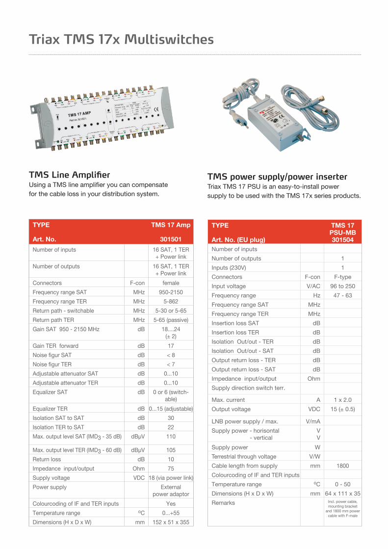
TMS Line AmplifierUsing a TMS line amplifier you can compensate for the cable loss in your distribution system.
TMS power supply/power inserterTriax TMS 17 PSU is an easy-to-install powersupply to be used with the TMS 17x series products.
TYPE
Art. No. (EU plug)
TMS 17 PSU-MB301504
Number of inputs
Number of outputs 1
Inputs (230V) 1
Connectors F-con F-type
Input voltage V/AC 96 to 250
Frequency range Hz 47 - 63
Frequency range SAT MHz
Frequency range TER MHz
Insertion loss SAT dB
Insertion loss TER dB
Isolation Out/out - TER dB
Isolation Out/out - SAT dB
Output return loss - TER dB
Output return loss - SAT dB
Impedance input/output Ohm
Supply direction switch terr.
Max. current A 1 x 2.0
Output voltage VDC 15 (± 0.5)
LNB power supply / max. V/mA
Supply power - horisontal - vertical
VV
Supply power W
Terrestrial through voltage V/W
Cable length from supply mm 1800
Colourcoding of IF and TER inputs
Temperature range oC 0 - 50
Dimensions (H x D x W) mm 64 x 111 x 35
Remarks Incl. power cable, mounting bracket
and 1800 mm power cable with F-male
Triax TMS 17x Multiswitches

Reduce your installation time with our range of outdoor wallcabinets pre-built with IRS equipment for 12-48 points.
Pre-Built Cabinets for IRS Installations
Part No. Product Description Cabinet Dimensions (mm)
370620 12 point cabinet 11S8 cabinet pre-assembled for 12 IRS points 800 x 516 x 240
370621 16 point cabinet 11S8 cabinet pre-assembled for 16 IRS points 800 x 516 x 240
370622 24 point cabinet 11S8 cabinet pre-assembled for 24 IRS points 800 x 516 x 240
370623 32 point cabinet 11S8 cabinet pre-assembled for 32 IRS points 800 x 516 x 240
370624 40 point cabinet 11S10 cabinet pre-assembled for 40 IRS points 940 x 790 x 325
370625 48 point cabinet 11S10 cabinet pre-assembled for 48 IRS points 940 x 790 x 325

Often the main reason people install a multiswitch system is to get access to a vast number of TV channels. In the UK you can potentially enjoy some 3-4000 channels in just one installation.
Triax offers you a professional range of multiswitches to meet your needs – ranging from large cascadable systems for up to 16 polarities and many users to single position multiswitches with a small number of users.
Below we’ve put together a short list to assist in your installations.
Don’t make compromises at the dish/antenna
Always use a dish size as large as possible. Signal level gained here is basically free, compared to what you may need to amplify later. Go for maximum performance and signal level and quality out of the dish and LNB.
Aim for symmetrical designs
When you design large installations, keep the distribution network balanced and symmetrical by starting with the dish, go half way down the building, then split upwards and downwards.
Always use thickest possible cable in the trunk and thinner on drops
The only way you can minimise large signal losses along a cable is to use a better, often thicker, cable. Avoid amplifiers as far as possible – and keep cascading amplifiers to a minimum.
Keep long cable runs in the trunk, not in subscriber cables
Remember, if you have long subscriber cables, the cable loss itself may force you to use a very high-level signal in the multiswitch – just to compensate.
Always carefully adjust the output level of line amplifiers
Whatever you do, NEVER just set line amplifiers for maximum output. Remember – the more transponders you use, the lower output level you have from the amplifier to avoid intermodulation distortion.
Keep subscriber drops as shortas possible
If using one single multiswitch unit forces you to run excessively long subscriber cables – then you should break it up into more, smaller units and let the trunk take care of the distances.
Be part of the decision-making team from an early stage
All too often, important decisions are made before the installer is contacted to install a complex multiswitch system. If you can influence these decisions you are improving your chances of a successfulinstallation.
The do’s and don’ts of multiswitch installations

Azimuth – see (Satellite) Position
13 VDC – selects vertical polarity.Your set-top box usually powers your LNB – and when you select a direct current of approximately 13 volts to reach the LNB it automatically receives vertical polarity signals only.
18 VDC – selects horizontal polarity.Your set-top box usually powers your LNB – and when you select a direct current of approximately 18 volts to reach the LNB it automatically receives horizontal polarity signals only.
22 kHz – switches between High or Low Band.Lets your set-top box tell your LNB to pick the High Band frequency range whenever 22 kHz is present as switching tone/indicator – and the Low Band when it isn’t. For more on this, please see DiSEqC below.
Backbone – see Trunk or Cascade
Cascade – a chain of multiswitches.You build a cascade, when you link two or more multi switches together in a chain – with the first serving as signal source for the next in line. Cables connecting cascaded multiswitches are often called the trunk or backbone.
DiSEqC – lets you switch between satellite positions.The Digital Sequence Equipment Control, or simply DiSEqC switch, makes it possible for you to receive signals from more than one satellite position. Dependent on how exactly the 22 kHz tone/indicator is transmitted, this switch determines from which satellite position you’ll be picking up signals.
Dish – collects and focuses satellite signals.Transponders on a satellite send out electromagnetic radiation which is then picked up by a satellite dish on Earth. The signal collected by the dish is then reflected to a focal point where the antenna, or LNB, is placed.
Elevation – viewing the satellite at the right angle.Specifies the angle of the satellite to the horizon. At the Equator this gives you an elevation of 90 degrees. In Central Germany it’s 32. In Denmark 26 – and in Central Sweden it’s down to 15 degrees.
Footprint – ground area covered by signal.The shape and size of an area on Earth where one specific transponder can be received. Footprints vary from simple, circular shapes to highly complex outlines – following geographical shapes on the Earth’s surface.
Headend - The equipment which follows the dish and aerial array enabling all signals to be processed and launched into the distribution system at the required levels.
High Band - Frequencies from a European satellite transponder range between 11.7 and 12.75 GHz.
IRS Integrated Reception SystemA TV distribution system which distributes satellite and terrestrial signals to all points.
Low Band - Frequencies from a European satellite transponder range between 10.7 and 11.7 GHz.
LNB – converting and amplifying high frequencies.Satellites transmit signals at high frequencies. When a band of satellite signals get reflected by a dish they merge in a focal point where the antenna, or Low Noise Block Converter (called LNB or LNC), is placed. The LNB then down-converts and amplifies the signals, effectively placing them in the useful and convenient 950-2150 MHz Satellite IF range.
Polarity – using the same frequency twice.Most satellite transponders transmit frequencies in both horizontal and vertical directions. The 90 degree difference in radiation angle – called horizontal and vertical polarity – isolates the frequencies from each other and prevents interference. Benefit? You can use the same frequency twice – ultimately doubling the number of TV channels available. In Europe, High and Low Band frequencies are used. And since both come with horizontal and vertical polarity this means that, in total, a satellite transmits four polarities. In the United States and the Pacific, usually only two-polarity satellites are used.
(Satellite) Position – plotting the orbit also known as Azimuth, this is the geographical position of the satelliteorbit relative to Greenwich; which is designated the ‘zero position’. Now, counting from zero, you can relate satellites to either a specific east or west position – e.g. Astra 19.2 degrees east or Thor 0.8-1 degrees west.
Terrestrial – TV and Radio signals in the frequency range 88-862 MHz transmitted from land based transmitters.
Transponder – transmitting electromagnetic radiation.Another name for the transmitter antennas on a satellite. Each satellite can have more than fifty transponders – transmitting on individual frequencies.
Trunk – cables in a cascade also known as the backbone, the trunk refers to cables running between multiswitches in cascade.
Quattro LNBUsed exclusively with multiswitches, this type of LNB gives you four outputs that are fixed individually to each of the four polarities – i.e. Low Band, horizontal polarity; Low Band, vertical polarity; High Band, horizontal polarity; and High Band, vertical polarity. A Quattro LNB needs four cables, one for each polarity.
“What we mean by...”

Triax Design On-Line
With ‘Design On-Line’ you can generate:
• A detailed schematic diagram using a library of ‘drag and drop’ Triax products
• Calculation of key system signal levels
• An indication of signal levels using a simple ‘traffic light’ system
• Automatically generate a Bill of Materials and Quotation based on the schematic diagram
• Allows you to customise the quotation to meet your own requirements
• Generate, save and print the schematic diagram and Bill of Materials in ‘PDF’ format
• Store your designs and easily access your quotations as required
• The software is automatically updated via the web - you always have access to the latest version
Save time - Design On-Line
For further updates visit our website www.triax.co.uk
Triax Design On-Line is our industry leading, web based system design software. The software has been designed for maximum flexibility and ease of use to efficiently create professional system designs.
The simple solution to producingprofessional system designs.
TRIAX - your ultimate connection

*Triax reserves the right to change the specifications without prior notification
Triax UK LtdAbergorki Industrial Estate, Treorchy, Rhondda Cynon Taff. South Wales CF42 6DL
Tel: 0845 601 0578 | Fax: 0845 601 1023 | [email protected]
Top Related