


Languages
Pages
Legal


1
“HARMONICS”
Causes, Effects, Solutions
K - FACTOR TRANSFORMERSHARMONIC MITIGATING TRANSFORMERS
I-TRAP NEUTRAL CURRENT REDUCER

2
WHAT ARE HARMONICS ?
HARMONICS: A sinusoidal waveform with a frequency that is an integral multiple of the fundamental frequency.
60hz Fundamental 120hz 2nd Harmonic
180hz 3rd Harmonic240hz 4th Harmonic
etc...Note: Each individual harmonic is sinusoidal.

3
Fundamental (60hz) & 5th Harmonic (300hz)
0
360

4
Sum of 60Hz & 300Hz(Fundamental & 5th harmonic)
0
360

5
Where Do Harmonics Originate?Harmonics primarily originate in electronic power converters.
These can be found in:1. Switch Mode Power Supplies2. Electronic Ballasts3. Variable Frequency Drives4. Oven and Furnace Controls5. Rectifier Circuits
6
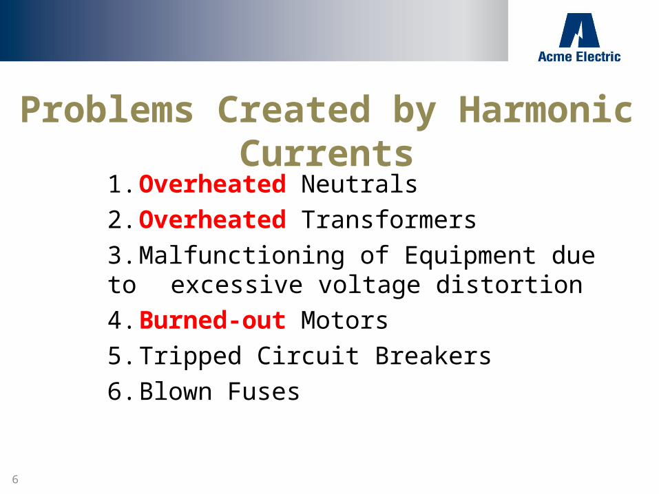
Problems Created by Harmonic Currents
1. Overheated Neutrals2. Overheated Transformers3. Malfunctioning of Equipment due to
excessive voltage distortion4. Burned-out Motors5. Tripped Circuit Breakers6. Blown Fuses

7
TRIPLEN HARMONICS
Triplen harmonics include the 3rd harmonic and all the odd multiples of the 3rd.
Example: 3rd, 9th, 15th, 21st, 27th, 33rd, etc
Note: Triplen harmonics tend to add up in the three phase neutral conductor.

8
TYPICAL 208Y/120 SYSTEM
9
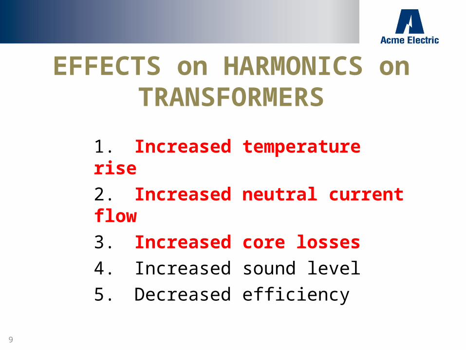
EFFECTS on HARMONICS on TRANSFORMERS
1. Increased temperature rise2. Increased neutral current flow3. Increased core losses4. Increased sound level5. Decreased efficiency
10
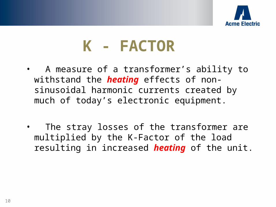
K - FACTOR• A measure of a transformer’s ability to withstand the
heating effects of non-sinusoidal harmonic currents created by much of today’s electronic equipment.
• The stray losses of the transformer are multiplied by the K-Factor of the load resulting in increased heating of the unit.
11
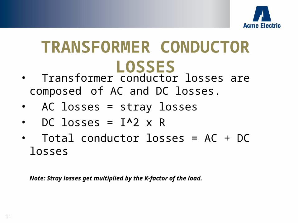
TRANSFORMER CONDUCTOR LOSSES
• Transformer conductor losses are composed of AC and DC losses.
• AC losses = stray losses• DC losses = I^2 x R• Total conductor losses = AC + DC losses
Note: Stray losses get multiplied by the K-factor of the load.

12
Example of TEMPERATURE RISETypical 75 kVA TP1
75 kVA, 3-Ph, 480 - 208Y/120, 150 degree riseTotal conductor losses at K-1 (linear load) = 2860 + 135 = 2995
If K=20 (non-linear load), new conductor losses are:2860 + (20 x 135) = 5560 watts
Rise @ K-1 = 150 degrees CRise @ K-20 = 244 degrees C

13
Three Solutions to HARMONIC PROBLEMS
1. K - Rated Transformers (traditional)
2. Harmonic Mitigating Transformers (zig-zag)
3. I-Trap Neutral Current Reducer
14
K - Rated Transformers
K - Rated or Non-Linear transformers do not eliminate harmonics!
They are only designed to tolerate the heating effects of harmonics created by much of today's electronic equipment.

15
K-Rated (continued)
K-rated transformers are traditional Delta-Wyetransformers
• They are designed with lower flux densities and noload losses as well as lower I²R losses resulting in a larger
and heavier unit.• They do not eliminate or cancel harmonics

16
K-Factor Features
Available in K-Factors of 4, 13, and 20
Aluminum or Copper windings.
Available temperature rises of 150, 115, or 80
UL listed and CSA certified

17
K-Factor and TP1
• As of January 1, 2007 K-Rated transformers must comply to the efficiency standards (TP1) of the National Energy Bill
• They are only required to comply with a connected load condition of K1 (no harmonics)

18
Acme Mitigating Transformer
19
Harmonic Mitigating Transformers How do they work?
They consist of a Delta primary and a Zig-Zag secondary.The Zig-Zag secondary causes a phase shift in the triplenharmonics which results in a canceling effect. Thisprevents the triplen harmonic losses from being coupledback into the primary and results in cooler operation andincreased energy efficiency.

20
What is a Zig-Zag winding?
The secondary winding on each magnetic leg of the coreis wound in two separate sections. These sections areThen transposed between different legs of the core toCreate the Zig-Zag secondary. Each 120 v output of thetransformer consists of two sections from differentmagnetic legs resulting in a magnetic phase shift

21
Diagram showing Delta primary and Zig-Zag secondary
( Zero degree angular displacement)
X0

22
Harmonic Mitigating Catalog Numbers
• CMT-53312-4S 30 KVA• CMT-53313-4S 45 KVA• CMT-53314-4S 75 KVA• CMT-53315-4S 112.5 KVA• CMT-53316-4S 150 KVA• CMT-53317-4S 225 KVA
Optional “TVSS” available on 208Y/120 output
23
Harmonic Mitigating Benefits
1. Unlike K-Rated transformers, Mitigating transformers actually treat the triplen harmonics in the Zig-Zag secondary winding
2. Reduce supply voltage flat topping caused by non-linear loads
3. Improve overall power factor of supply system4. Suitable for K-Factor loads5. Improved energy efficiency (Meet TP1 at K-1 load)
24
Mitigating Transformer Features
• Copper foil conductor to minimize “skin effect” of harmonic currents
• Taps: 2 x 2.5% ANFC and BNFC• 220 Degree C insulation system with 150 Degree C
rise• UL listed and CSA certified• Zero degree angular displacement between
Primary and Secondary windings

25
Important Points to Remember
• Harmonic mitigating transformers don’t treat harmonics or neutral current until they reach the transformer windings
• Transformer has 200% Neutral Bar• Neutral conductor from transformer to Load Panel
should be sized at 200%
26
ACME ADVANTAGES
1. Acme utilizes special winding techniques and “foil” conductors in both its K-Factor and Harmonic Mitigating transformers to minimize the heating effects of harmonic currents. (Skin effect)
2. The use of foil conductor increases the dielectric strength of the insulation because one layer is only one turn. Foil also eliminates the effects of axial forces which can result in failure of wire wound transformers.
27
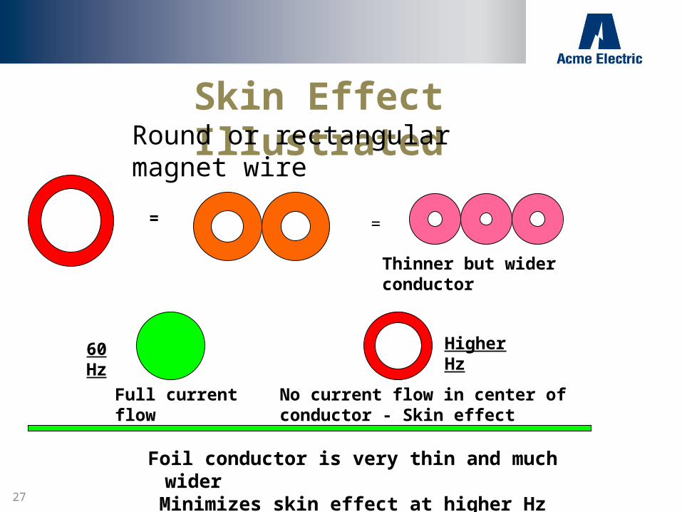
Skin Effect IllustratedRound or rectangular magnet wire
= =
60 Hz Higher Hz
Foil conductor is very thin and much wider Minimizes skin effect at higher Hz
No current flow in center of conductor - Skin effect
Thinner but wider conductor
Full current flow

28
Applications
• Hospitals and Health Care Facilities• Commercial & Educational Facilities• Airport Facilities• Telecom Facilities• Broadcasting Facilities• Internet Service Providers• Data Centers

29
I-Trap Neutral Current Reducer
Technical Description:• Low impedance - Zero sequence• Auto Zig-Zag transformer
30
I-Trap Applications
1. It is used to reduce excessive current flow in the neutral of a 3 phase 208Y/120 volt system.
2. It is available in ampere ratings of 100, 150, 300, and 450. It includes a front mounted amp meter for monitoring neutral current.
3. Target areas: Data processing centers, Hospitals, Radio and TV stations, Large computer labs, etc. (Any area having numerous electronic 120v loads powered from a 208Y/120 system)

31
How Does The I-Trap Work?• Third harmonic currents are “in-phase” (additive) in the three
phase neutral.• The low impedance and auto Zig-Zag characteristics of
the I-Trap target the third harmonic currents causingthem to become “out of phase” in the three phaseneutral, resulting in a canceling effect. Reductions of50% to 90% are typical.
• In many applications, the Acme I-Trap provides an easier and more affordable solution than replacing existing Neutral conductors.
32
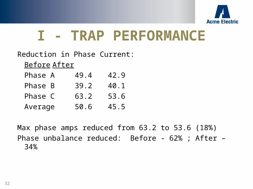
I - TRAP PERFORMANCEReduction in Phase Current:
Before AfterPhase A 49.4 42.9Phase B 39.2 40.1Phase C 63.2 53.6Average 50.6 45.5
Max phase amps reduced from 63.2 to 53.6 (18%)Phase unbalance reduced: Before - 62% ; After – 34%

33
Performance DataPhase A B CI-Trap Out In Out In Out In RMS 49.4 42.9 39.2 40.1 63.2 53.6 1H 39.0 40.0 31.0 38.0 51.0 50.0 3H 27.0 1.0 21.0 3.0 34.0 10.0 5H 13.0 15.0 11.0 13.0 15.0 16.0 7H 4.0 4.0 4.0 5.0 3.0 4.0 9H 1.0 --- 1.0 1.0 1.0 1.211H 1.0 --- 1.0 --- 1.0 ---Har. Dist. 78.2% 37.7% 77.6% 39.0% 73.2% 38.0%K – Factor 5.5 4.4 5.8 4.3 4.8 3.8

34
Reduction In Neutral Current I - Trap Out In RMS 84.8 8.1
1H 17.0 1.0 3H 83.0 8.0 5H 3.0 --- 7H 2.0 --- 9H 1.0 ---
11H 1.0 ---

35
Questions?
Top Related