


Languages
Pages
Legal


Foundation Design 14-1Instructional Materials Complementing FEMA 451, Design Examples
FOUNDATION DESIGN
Proportioning elements for:Transfer of seismic forcesStrength and stiffnessShallow and deep foundationsElastic and plastic analysis
Foundation Design 14-2Instructional Materials Complementing FEMA 451, Design Examples
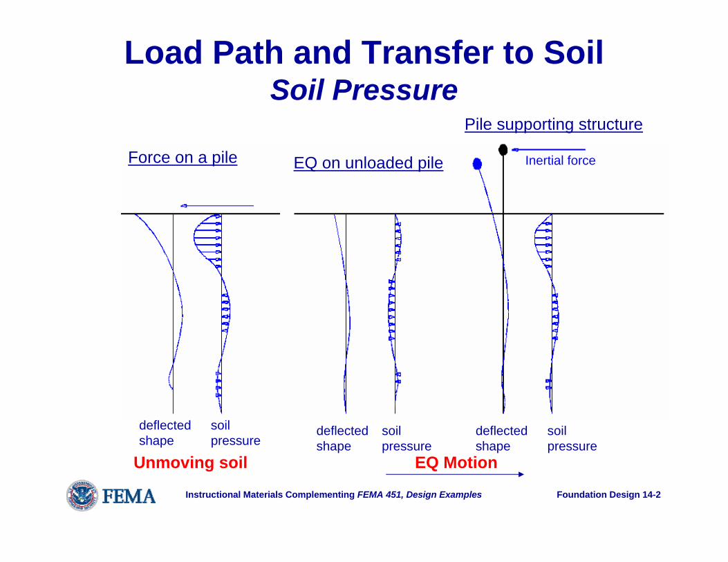
Load Path and Transfer to SoilSoil Pressure
Force on a pile EQ on unloaded pile
Pile supporting structure
Inertial force
Unmoving soil EQ Motion
deflectedshape
soilpressure
deflectedshape
deflectedshape
soilpressure
soilpressure

Foundation Design 14-3Instructional Materials Complementing FEMA 451, Design Examples
Load Path and Transfer to SoilSoil-to-foundation Force Transfer
EQ motion
Passive earthpressure
Friction
Shallow

Foundation Design 14-4Instructional Materials Complementing FEMA 451, Design Examples
Load Path and Transfer to SoilSoil-to-foundation Force Transfer
Deep
EQ Motion
MotionSoil
pressureBendingmoment

Foundation Design 14-5Instructional Materials Complementing FEMA 451, Design Examples
Load Path and Transfer to SoilVertical Pressures - Shallow
EQ motion
Overturning moment

Foundation Design 14-6Instructional Materials Complementing FEMA 451, Design Examples
Load Path and Transfer to SoilVertical Pressures - Deep
EQ Motion
Overturningmoment

Foundation Design 14-7Instructional Materials Complementing FEMA 451, Design Examples
Reinforced Concrete Footings: Basic Design Criteria (concentrically loaded)
d/2 (all sides)
(c) Critical sectionfor two-way shear
(b)Critical sectionfor one-way shear
(a)Critical sectionfor flexure
Outside face of concretecolumn or line midwaybetween face of steelcolumn and edge ofsteel base plate (typical)
extent of footing(typical)
d

Foundation Design 14-8Instructional Materials Complementing FEMA 451, Design Examples
Footing Subject to Compression and Moment: Uplift Nonlinear
(a)Loading
(b)Elastic, no uplift
(c)Elastic, at uplift
(d)Elastic, after uplift
(e)Some plastification
(f)Plastic limit
MP

Foundation Design 14-9Instructional Materials Complementing FEMA 451, Design Examples
Example7-story Building:Shallow foundations designed for perimeter frame and core bracing.
5 B
ays @
25'
-0"
= 12
5'-0
"1'
-2"
1'-2" 7 Bays @ 25'-0" = 175'-0" 1'-2"
N

Foundation Design 14-10Instructional Materials Complementing FEMA 451, Design Examples
Shallow Footing Examples
Soil parameters:• Medium dense sand• (SPT) N = 20• Density = 120 pcf• Friction angle = 33o
Gravity load allowables• 4000 psf, B < 20 ft• 2000 psf, B > 40 ftBearing capacity (EQ)• 2000B concentric sq.• 3000B eccentric
φ = 0.6

Foundation Design 14-11Instructional Materials Complementing FEMA 451, Design Examples
Footings proportioned for gravity loads alone
Corner:6'x6'x1'-2" thick
Perimeter:8'x8'x1'-6" thick
Interior:11'x11'x2'-2" thick

Foundation Design 14-12Instructional Materials Complementing FEMA 451, Design Examples
Design of Footings for Perimeter Moment Frame
5 at
25'
-0"
7 at 25'-0"
N

Foundation Design 14-13Instructional Materials Complementing FEMA 451, Design Examples
7-Story Frame, Deformed

Foundation Design 14-14Instructional Materials Complementing FEMA 451, Design Examples
Combining Loads
• Maximum downward load:1.2D + 0.5L + E
• Minimum downward load:0.9D + E
• Definition of seismic load effect E:E = ρ1QE1 + 0.3 ρ2QE2+/- 0.2 SDSDρx = 1.08 ρy = 1.11 and SDS = 1.0

Foundation Design 14-15Instructional Materials Complementing FEMA 451, Design Examples
Reactions
PMxx
Myy
PMxx
Myy
-281.0 k-891.0 k-ft13.4 k-ft
-51.8 k47.7 k-ft-246.9 k-ft
22.3 k103.5 kA-6
21.3 k-1011.5 k-ft8.1 k-ft
-3.8 k53.6 k-ft-243.1 k-ft
43.8 k203.8 kA-5
EyExLiveDeadGrid

Foundation Design 14-16Instructional Materials Complementing FEMA 451, Design Examples
Reduction of Overturning Moment
• NEHRP Recommended Provisions allow base overturning moment to be reduced by 25% at the soil-foundation interface.
• For a moment frame, the column vertical loads are the resultants of base overturning moment, whereas column moments are resultants of story shear.
• Thus, use 75% of seismic vertical reactions.

Foundation Design 14-17Instructional Materials Complementing FEMA 451, Design Examples
Additive Load w/ Largest Eccentricity
• At A5: P = 1.4(203.8) + 0.5(43.8) + 0.75(0.32(-3.8) + 1.11(21.3)) = 324 k
Mxx = 0.32(53.6) + 1.11(-1011.5) = -1106 k-ft• At A6: P = 1.4(103.5) + 0.5(22.3) +
0.75(0.32(-51.8) + 1.11(-281)) = -90.3 kMxx = 0.32(47.7) + 1.11(-891) = -974 k-ft
• Sum Mxx = 12.5(-90.3-324) -1106 -974 = -7258

Foundation Design 14-18Instructional Materials Complementing FEMA 451, Design Examples
Counteracting Load with Largest e
• At A-5: P = 0.7(203.8) + 0.75(0.32(-3.8) + 1.11(21.3)) = 159.5 k
Mxx = 0.32(53.6) + 1.11 (-1011.5) = -1106 k-ft• At A-6: P = 0.7(103.5) + 0.75(0.32(-51.8) +
1.11(-281)) = -173.9 kMxx = 0.32(47.7) + 1.11(-891) = -974 k-ft
• Sum Mxx = 6240 k-ft

Foundation Design 14-19Instructional Materials Complementing FEMA 451, Design Examples
Elastic Response
• Objective is to set L and W to satisfy equilibrium and avoid overloading soil.
• Successive trials usually necessary.
PM
W
R
L
e

Foundation Design 14-20Instructional Materials Complementing FEMA 451, Design Examples
Additive Combination
Given P = 234 k, M =7258 k-ftTry 5 foot around, thus L = 35 ft, B = 10 ft• Minimum W = M/(L/2) – P = 181 k = 517 psfTry 2 foot soil cover & 3 foot thick footing• W = 245 k; for additive combo use 1.2W• Qmax = (P + 1.2W)/(3(L/2 – e)B/2) = 9.4 ksf• φQn = 0.6(3)Bmin = 10.1 ksf, OK by Elastic

Foundation Design 14-21Instructional Materials Complementing FEMA 451, Design Examples
Plastic Response
• Same objective as for elastic response.
• Smaller footings can be shown OK thus:
PM
W
R
L
eR

Foundation Design 14-22Instructional Materials Complementing FEMA 451, Design Examples
Counteracting Case
Given P = -14.4 k; M = 6240Check prior trial; W = 245 k (use 0.9W)• e = 6240/(220.5 – 14.4) = 30.3 > 35/2 NGNew trial: L = 40 ft, 5 ft thick• W = 400 k; e = 18.0 ft; plastic Qmax= 8.6 ksf• φQn = 0.6(3)4 = 7.2 ksf, close• Solution is to add 5 k, then e = 17.8 ft and
Qmax = φQn = 7.9 ksf

Foundation Design 14-23Instructional Materials Complementing FEMA 451, Design Examples
Additional Checks
• Moments and shears for reinforcement should be checked for the overturning case.
• Plastic soil stress gives upper bound on moments and shears in concrete.
• Horizontal equilibrium: Hmax< φμ(P+W)in this case friction exceeds demand; passive could also be used.
Foundation Design 14-24Instructional Materials Complementing FEMA 451, Design Examples
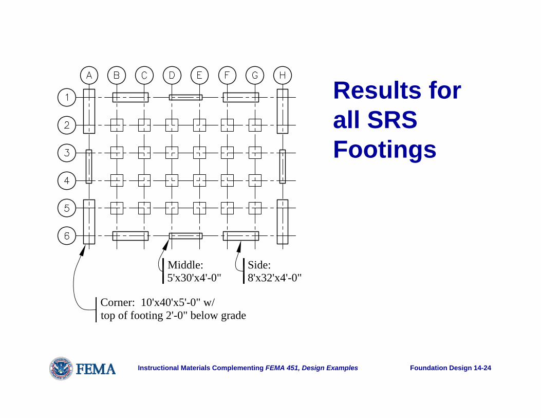
Results for all SRS Footings
Corner: 10'x40'x5'-0" w/top of footing 2'-0" below grade
Middle:5'x30'x4'-0"
Side:8'x32'x4'-0"

Foundation Design 14-25Instructional Materials Complementing FEMA 451, Design Examples
Design of Footings for Core-braced 7-story Building
25 foot square bays at center of building

Foundation Design 14-26Instructional Materials Complementing FEMA 451, Design Examples
Solution for Central Mat
Mat: 45'x95'x7'-0"with top of mat 3'-6" below grade
Very high uplifts at individual columns; mat is only practical shallow foundation.

Foundation Design 14-27Instructional Materials Complementing FEMA 451, Design Examples
Bearing Pressure Solution
(a)Plasticsolution
(b)Elastic solutionpressures (ksf)0
4 812 16
12.2 ksf
~
Plastic solution is satisfactory; elastic is not; see linked file for more detail.

Foundation Design 14-28Instructional Materials Complementing FEMA 451, Design Examples
Pile/Pier Foundations
Passive resistance(see Figure 4.2-5)
p-y springs(see Figure 4.2-4)
Pilecap
Pile
View of cap with column above and piles below.

Foundation Design 14-29Instructional Materials Complementing FEMA 451, Design Examples
Pile/Pier FoundationsPile Stiffness:• Short (rigid)• Intermediate• LongCap influenceGroup action
Soil Stiffness• Linear springs –
nomographs e.g. NAVFAC DM7.2
• Nonlinear springs –LPILE or similar analysis

Foundation Design 14-30Instructional Materials Complementing FEMA 451, Design Examples
Site Class E, depth = 10 ftSite Class E, depth = 30 ftSite Class C, depth = 10 ftSite Class C, depth = 30 ft
0.01
Soil
resi
stan
ce, p
(lb/
in.)
10
100
1,000
10,000
0.2 0.1 0.3
Pile deflection, y (in.)
0.4 0.5 0.6 0.7
100,000
0.90.8 1.0
Sample p-y Curves

Foundation Design 14-31Instructional Materials Complementing FEMA 451, Design Examples
Passive Pressure
0.05
0.6
0.2
0
0.10.0
0.01
P/P ul
t
0.50.40.3
1.00.90.80.7
0.03 0.02 0.04δ/H
0.06

Foundation Design 14-32Instructional Materials Complementing FEMA 451, Design Examples
Group Effect
1
0.0
0.2
2
Gro
up e
ffec
t fac
tor
0.4
0.6
0.8
1.0
5 3Group size (piles per side)
4
s = 1.5 D
s = 2 D
s = 3 Ds = 4 D

Foundation Design 14-33Instructional Materials Complementing FEMA 451, Design Examples
Pile Shear: Two Soil Stiffnesses
30
25
20
15
10
5
0
-5 0 5 10 15Shear, V (kip)
Dep
th (f
t)
Site Class C
Site Class E

Foundation Design 14-34Instructional Materials Complementing FEMA 451, Design Examples
Pile Moment vs Depth
30
25
20
15
10
5
0
-1000 -500 0 500Moment, M (in.-kips)
Dep
th (f
t)
Site Class C
Site Class E

Foundation Design 14-35Instructional Materials Complementing FEMA 451, Design Examples
Pile Reinforcement
(4) #5
#4 spiral at11 inch pitch
(6) #5
#4 spiral at7.5 inch pitch
(6) #5
#4 spiral at3.75 inch pitch
4" pile embedment
Section A
Section B
Section C
C
B
A
21'-0
"23
'-0"
6'-4
"
•Site Class C•Larger amounts where moments and shears are high•Minimum amounts must extend beyond theoretical cutoff points•“Half” spiral for 3D

Foundation Design 14-36Instructional Materials Complementing FEMA 451, Design Examples
Pile Design
(4) #7
#4 spiral at11 inch pitch
(6) #7
#5 spiral at3.5 inch pitch
(8) #7
#5 spiral at3.5 inch pitch
4" pile embedment
B
A
32'-0
"20
'-0"
12'-4
"
Section A
Section B
Section C
C
•Site Class E•Substantially more reinforcement•“Full” spiral for 7D•Confinement at boundary of soft and firm soils (7D up and 3D down)

Foundation Design 14-37Instructional Materials Complementing FEMA 451, Design Examples
Other Topics for Pile Foundations
• Foundation Ties: F = PG(SDS/10)• Pile Caps: high shears, rules of thumb; look
for 3D strut and tie methods in future• Liquefaction: another topic• Kinematic interaction of soil layers
Foundation Design 14-38Instructional Materials Complementing FEMA 451, Design Examples
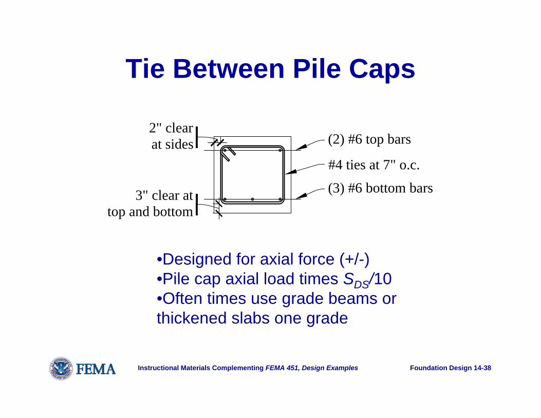
Tie Between Pile Caps
(2) #6 top bars
(3) #6 bottom bars#4 ties at 7" o.c.
2" clearat sides
3" clear attop and bottom
•Designed for axial force (+/-) •Pile cap axial load times SDS/10•Often times use grade beams or thickened slabs one grade
Top Related