


Languages
Pages
Legal

2017-11-12
1
Timers and Counters
Erasmus 2017/2018, PK-WIEiK
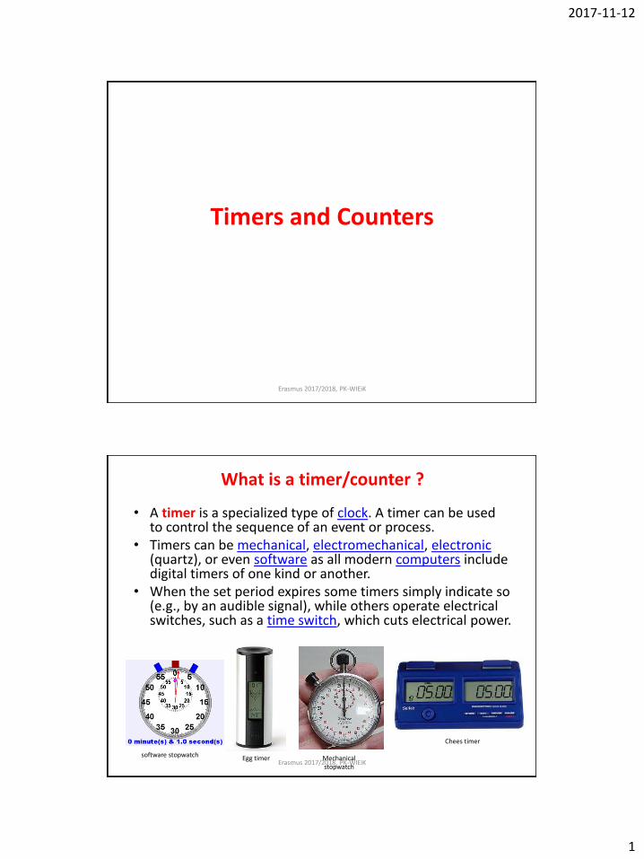
What is a timer/counter ?
• A timer is a specialized type of clock. A timer can be used to control the sequence of an event or process.
• Timers can be mechanical, electromechanical, electronic (quartz), or even software as all modern computers include digital timers of one kind or another.
• When the set period expires some timers simply indicate so (e.g., by an audible signal), while others operate electrical switches, such as a time switch, which cuts electrical power.
Egg timer
Chees timer
Mechanical stopwatch
software stopwatch Erasmus 2017/2018, PK-WIEiK

2017-11-12
2
What is a timer/counter ?
• In digital logic and computing, a counter is a device which stores (and sometimes displays) the number of times a particular event or process has occurred, often in relationship to a clock signal.
Mechanical counter
electronic counter
Multi-Function Digital Counter /
Timer / Tachometer
Erasmus 2017/2018, PK-WIEiK
RTC – Real Time Clock • A real-time clock (RTC) is a computer clock (most often in the form of an
integrated circuit) that keeps track of the current time and date. • Although the term often refers to the devices in personal computers,
servers and embedded systems, RTCs are present in almost any electronic device which needs to keep accurate time (mobile phone, GPS receiver, palmtop ..)
Dallas semiconductor real time clock from an older
PC. This version also contains a battery backed
SRAM
Erasmus 2017/2018, PK-WIEiK
• The DS1307 Serial Real-Time Clock is a low-power, full binary-coded decimal (BCD) clock/calendar plus 56 bytes of NV SRAM. Address and data are transferred serially via a 2-wire (I2C), bi-directional bus.
• The clock/calendar provides seconds, minutes, hours, day, date, month, and year information. The end of the month date is automatically adjusted for months with fewer than 31 days, including corrections for leap year.
• The clock operates in either the 24-hour or 12-hour format with AM/PM indicator.
• The DS1307 has a built-in power sense circuit that detects power failures and automatically switches to the battery supply.

2017-11-12
3
Digital counters
In electronics, digital counters can be implemented quite easily using register-type circuits such as the flip-flop, and a wide variety of classifications exist:
– Asynchronous (ripple) counter – changing state bits are used as clocks to subsequent state flip-flops
– Synchronous counter – all state bits change under control of a single clock – Decade counter – counts through ten states per stage – Up/down counter – counts both up and down, under command of a control
input – Ring counter – formed by a shift register with feedback connection in a ring – Johnson counter – a twisted ring counter – Cascaded counter
• Each is useful for different applications. Usually, counter circuits are digital in nature, and count in natural binary (BIN). Occasionally there are advantages to using a counting sequence other than the natural binary sequence—such as the binary coded decimal (BCD) counter, a linear feedback shift register counter, or a Gray-code counter.
• Counters are useful for digital clocks and timers, and in oven timers, VCR clocks, etc.
Erasmus 2017/2018, PK-WIEiK
Timer/counter in microprocessor system
• A counter is one of many registers in a modern microprocessor and simply counts events, that is, electrical pulses.
• Each time a pulse is applied to a counter, the value in the counter increments by one.
• If the pulses are applied at a known, constant rate, then the counter becomes a timer.
• Knowing the pulse rate and a count, we can easily compute a time value. • For example, if the pulse rate is 100 pulses per second (each pulse is 1/100th of a
second long) and our counter has counted 20 pulses, then 0.20 seconds has elapsed. (20 pulses) / (100pulses/second) = 0.20 seconds.
Time [s]
Time [s]
Pulses
Counter
Period t=0.01s
20
10
0
Frequency f=100Hz f=1/t
0ms 200ms 100ms
Erasmus 2017/2018, PK-WIEiK
2017-11-12
4
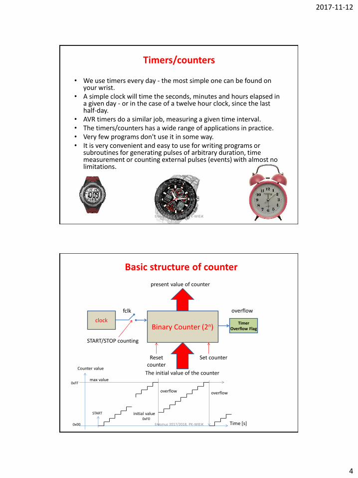
Timers/counters
• We use timers every day - the most simple one can be found on your wrist.
• A simple clock will time the seconds, minutes and hours elapsed in a given day - or in the case of a twelve hour clock, since the last half-day.
• AVR timers do a similar job, measuring a given time interval. • The timers/counters has a wide range of applications in practice. • Very few programs don't use it in some way. • It is very convenient and easy to use for writing programs or
subroutines for generating pulses of arbitrary duration, time measurement or counting external pulses (events) with almost no limitations.
Erasmus 2017/2018, PK-WIEiK
Basic structure of counter
Binary Counter (2n)
The initial value of the counter
present value of counter
overflow
clock
fclk
START/STOP counting
Reset counter
Set counter
Timer Overflow Flag
Time [s]
Counter value
START
0x00
0xFF max value
initial value 0xF0
overflow overflow
Erasmus 2017/2018, PK-WIEiK

2017-11-12
5
Timer/counters limits To understand timer/counters we must know their limits.
There are two limits: 1. the pulse properties (minimum pulse width and duration).
– When using the internal clock sources (those provided by the processor), we don’t have to worry about the minimum pulse properties.
– However, these must be considered if we’re driving the counter with an external signal.
Period
toff ton
Period T=toff + ton
Frequency f=1/T
limits toff = minimum „0” pulse width [s] ton = minimum „1” pulse width [s] f = maximum frequency [Hz]
Counter Input signal (internal or external)
Output word
Overflow bit
Erasmus 2017/2018, PK-WIEiK
Timer/counters limits 2. The maximum value that can be counted to.
– The other limit, maximum count value, is determined by the width of the register in bits.
– An eight bit wide counter can count to 28-1 or 255 (0 to 255, 0x00 to 0xFF), while a 16 bit wide counter can count to 216-1 or 65,535 (0 to 65535, 0x00 to 0xFFFF).
– On the 256th count (or 65,536th count), the counter starts over at zero. We say that the counter rolls over, or overflows, when this happens.
– If we don’t stop the timer/counter before it reaches its maximum value, it overflows, or starts counting again from zero. Unless we keep track of each time an overflow occurs, we can’t know the real time. Effectively, we extend the width of the counter register using software.
Time [s]
Maximum value (TOP VALUE)
minimum value=0 (BOTTOM VALUE)
Start counting
For 8-bit counter 0,1,2,3,4,....253,254,255, 0,1,2,3,4,...253,254,255,0,1,2..
Counter Value
counter overflow counter overflow
Erasmus 2017/2018, PK-WIEiK
2017-11-12
6
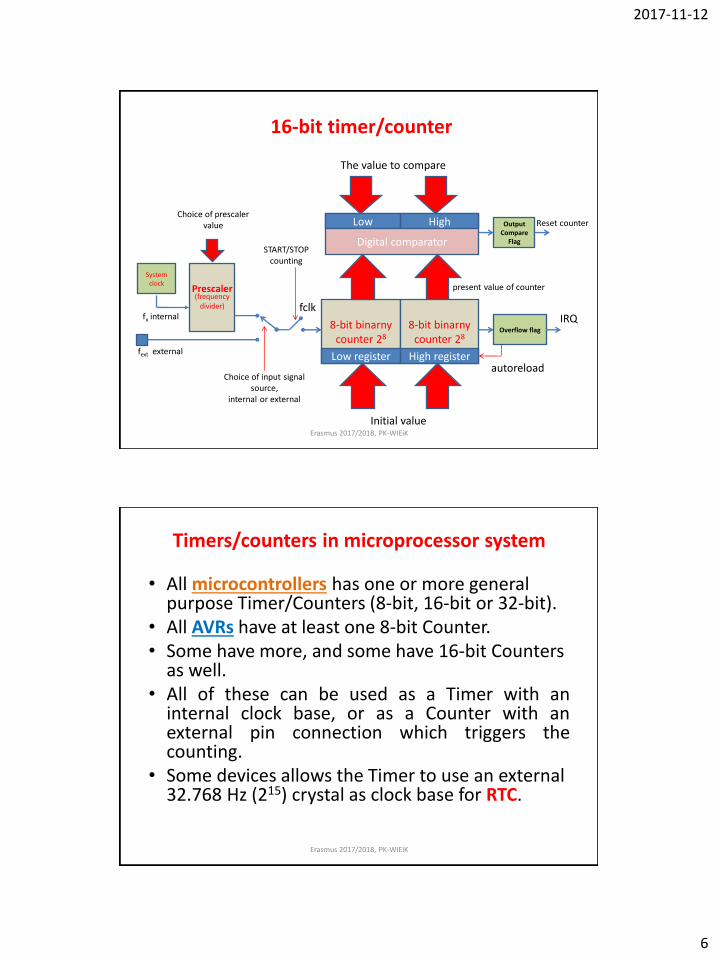
16-bit timer/counter
8-bit binarny counter 28
Initial value
present value of counter
autoreload
Prescaler (frequency
divider) fclk IRQ
START/STOP counting
8-bit binarny counter 28
Overflow flag
Choice of prescaler value
Low register
Digital comparator
High register
System clock
Choice of input signal source,
internal or external
fx internal
Output Compare
Flag
fext external
The value to compare
Low High Reset counter
Erasmus 2017/2018, PK-WIEiK
Timers/counters in microprocessor system
• All microcontrollers has one or more general purpose Timer/Counters (8-bit, 16-bit or 32-bit).
• All AVRs have at least one 8-bit Counter. • Some have more, and some have 16-bit Counters
as well. • All of these can be used as a Timer with an
internal clock base, or as a Counter with an external pin connection which triggers the counting.
• Some devices allows the Timer to use an external 32.768 Hz (215) crystal as clock base for RTC.
Erasmus 2017/2018, PK-WIEiK

2017-11-12
7
Timers/counters in AVR MCU
• The timer systems on the AVR series of Microcontrollers are complex.
• They have a myriad of uses ranging from simple delay intervals right up to complex PWM generation.
• However, despite the surface complexity, the function of the timer subsystem can be condensed into one obvious function: to time.
Erasmus 2017/2018, PK-WIEiK
Timers/counters in AVR MCU
• The AVR timers are very useful as they can run asynchronous to the main AVR core.
• This is a fancy way of saying that the timers are separate circuits on the AVR chip which can run independent of the main program, interacting via the control and count registers, and the timer interrupts.
• Timers can be configured to produce outputs directly to pre-determined pins, reducing the processing load on the AVR core.
• One thing that trips those new to the AVR timer is the clock source. Like all digital systems, the timer requires a clock in order to function.
• As each clock pulse increments the timer's counter by one, the timer measures intervals in periods of one on the input frequency.
Timer Resolution = (1 / Input Frequency)
Erasmus 2017/2018, PK-WIEiK
2017-11-12
8
Timers/counters in ATMEGA32 ATMEGA16 or ATMGA32 has: • two 8-bit Timer/Counters with Separate Prescalers and Compare Modes – T0, T2 • One 16-bit Timer/Counter with Separate Prescaler, Compare Mode, and Capture Mode –T1. • Real Time Counter with Separate Oscillator – using T2 • Programmable Watchdog Timer with Separate On-chip Oscillator
T2 - Timer/Counter2 is a general purpose, single compare unit, 8-bit Timer/Counter module.
The main features are:
•Single Compare unit Counter
•Clear Timer on Compare Match (Auto Reload)
•Glitch-free, Phase Correct Pulse Width Modulator (PWM)
•Frequency Generator
•10-bit Clock Prescaler
•Overflow and Compare Match Interrupt Sources (TOV2 and OCF2)
•Allows clocking from External 32kHz Watch Crystal Independent of the I/O Clock
T1 – 16-bit Timer/Counter1 unit allows accurate program execution timing (event management), wave generation, and signal timing measurement. The main features are: • True 16-bit Design (that is, allows 16-bit
PWM) • Two Independent Output Compare Units •Double Buffered Output Compare Registers •One Input Capture Unit • Input Capture Noise Canceler • Clear Timer on Compare Match (Auto
Reload) •Glitch-free, Phase Correct Pulse Width
Modulator (PWM) •Variable PWM Period • Frequency Generator • External Event Counter • Four Independent Interrupt Sources (TOV1,
OCF1A, OCF1B, and ICF1)
T0 - Timer/Counter0 is a general purpose, single compare unit, 8-bit Timer/Counter module.
The main features are:
•Single Compare Unit Counter
•Clear Timer on Compare Match (Auto Reload)
•Glitch-free, Phase Correct Pulse Width Modulator (PWM)
•Frequency Generator
•External Event Counter
•10-bit Clock Prescaler
•Overflow and Compare Match Interrupt Sources (TOV0 and OCF0)
Erasmus 2017/2018, PK-WIEiK
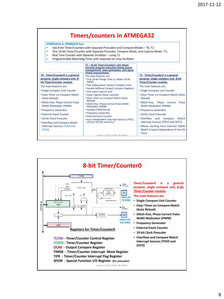
8-bit Timer/Counter0
Timer/Counter0 is a general purpose, single compare unit, 8-bit Timer/Counter module.
The main features are:
• Single Compare Unit Counter
• Clear Timer on Compare Match (Auto Reload)
• Glitch-free, Phase Correct Pulse Width Modulator (PWM)
• Frequency Generator
• External Event Counter
• 10-bit Clock Prescaler
• Overflow and Compare Match Interrupt Sources (TOV0 and OCF0)
Registers for Timer/Counter0
TCCR0 - Timer/Counter Control Register TCNT0 - Timer/Counter Register OCR0 - Output Compare Register TIMSK - Timer/Counter Interrupt Mask Register TIFR - Timer/Counter Interrupt Flag Register SFIOR - Special Function I/O Register (for prescaler)
Input pin T0 (PB0)
output pin OC0 (PB3)
Erasmus 2017/2018, PK-WIEiK
2017-11-12
9
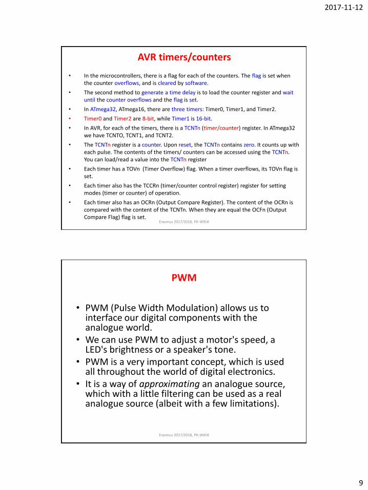
AVR timers/counters
• In the microcontrollers, there is a flag for each of the counters. The flag is set when the counter overflows, and is cleared by software.
• The second method to generate a time delay is to load the counter register and wait until the counter overflows and the flag is set.
• In ATmega32, ATmega16, there are three timers: Timer0, Timer1, and Timer2.
• Timer0 and Timer2 are 8-bit, while Timer1 is 16-bit.
• In AVR, for each of the timers, there is a TCNTn (timer/counter) register. In ATmega32 we have TCNTO, TCNT1, and TCNT2.
• The TCNTn register is a counter. Upon reset, the TCNTn contains zero. It counts up with each pulse. The contents of the timers/ counters can be accessed using the TCNTn. You can load/read a value into the TCNTn register
• Each timer has a TOVn (Timer Overflow) flag. When a timer overflows, its TOVn flag is set.
• Each timer also has the TCCRn (timer/counter control register) register for setting modes (timer or counter) of operation.
• Each timer also has an OCRn (Output Compare Register). The content of the OCRn is compared with the content of the TCNTn. When they are equal the OCFn (Output Compare Flag) flag is set.
Erasmus 2017/2018, PK-WIEiK
PWM
• PWM (Pulse Width Modulation) allows us to interface our digital components with the analogue world.
• We can use PWM to adjust a motor's speed, a LED's brightness or a speaker's tone.
• PWM is a very important concept, which is used all throughout the world of digital electronics.
• It is a way of approximating an analogue source, which with a little filtering can be used as a real analogue source (albeit with a few limitations).
Erasmus 2017/2018, PK-WIEiK

2017-11-12
10
PWM Technique
Period
Pulse width
T- period of PWM signal [s], T = toff + ton
F = 1/T – frequency of PWM signal [Hz] toff - ‘off' time [s] ton - 'on' time [s] Uavg = Umax*ton/T – average output voltage ton/T - variable duty cycle
Off time regulation
toff
T
ton
Umax
Uavg
Period
toff
T
ton On time regulation
OUT
On time regulation
/OUT
dead time
Period
toff
T Off time regulation
toff
ton complementary
outputs
Erasmus 2017/2018, PK-WIEiK
PWM • It's important to note that PWM does not change our AVR's limitations; the signal sent out by the timer is still a true digital signal.
• However, by altering the on and off time of the signal at a given frequency, we can adjust the average on time to give an approximate analogue signal.
• This signal is good enough for immediate use in many applications - including motor speed control and LED dimming - without any extra filtering, or with the addition of a capacitor the output can be smoothed to a real analogue wave.
The top waveform is a traditional analogue signal, varying smoothly from GND to VCC volts. The bottom waveform is a digital representation of the top, using PWM. PWM allows us to set an overall frequency, and then vary the on and off time (called the duty cycle) of the output within each timer cycle. A longer duty cycle gives a longer on time, resulting in an analogue representation closer to the VCC voltage. A duty cycle of 100% (on for the entire cycle) gives a VCC output, while a duty cycle of 0% (off for the entire cycle) gives a GND output.
Erasmus 2017/2018, PK-WIEiK
2017-11-12
11
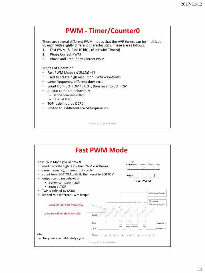
PWM - Timer/Counter0
There are several different PWM modes that the AVR timers can be initialized in, each with slightly different characteristics. These are as follows: 1. Fast PWM (8, 9 or 10 bit) , (8-bit with Timer0) 2. Phase Correct PWM 3. Phase and Frequency Correct PWM Modes of Operation: • Fast PWM Mode (WGM1:0 =3) • used to create high resolution PWM waveforms • same frequency, different duty cycle • count from BOTTOM to 0xFF, then reset to BOTTOM • output compare behaviour:
– set on compare match – reset at TOP
• TOP is defined by OCR0 • limited to 7 different PWM frequencies
Erasmus 2017/2018, PK-WIEiK
Fast PWM Mode
Fast PWM Mode (WGM1:0 =3) • used to create high resolution PWM waveforms • same frequency, different duty cycle • count from BOTTOM to 0xFF, then reset to BOTTOM • output compare behaviour:
• set on compare match • reset at TOP
• TOP is defined by OCR0 • limited to 7 different PWM frequencies
note: fixed frequency, variable duty cycle
compare value sets duty cycle
value of TOP sets frequency
Erasmus 2017/2018, PK-WIEiK
2017-11-12
12
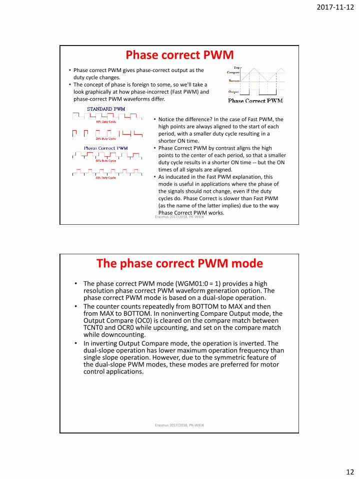
Phase correct PWM • Phase correct PWM gives phase-correct output as the
duty cycle changes. • The concept of phase is foreign to some, so we'll take a
look graphically at how phase-incorrect (Fast PWM) and phase-correct PWM waveforms differ.
• Notice the difference? In the case of Fast PWM, the high points are always aligned to the start of each period, with a smaller duty cycle resulting in a shorter ON time.
• Phase Correct PWM by contrast aligns the high points to the center of each period, so that a smaller duty cycle results in a shorter ON time -- but the ON times of all signals are aligned.
• As inducated in the Fast PWM explanation, this mode is useful in applications where the phase of the signals should not change, even if the duty cycles do. Phase Correct is slower than Fast PWM (as the name of the latter implies) due to the way Phase Correct PWM works.
Erasmus 2017/2018, PK-WIEiK
The phase correct PWM mode
• The phase correct PWM mode (WGM01:0 = 1) provides a high resolution phase correct PWM waveform generation option. The phase correct PWM mode is based on a dual-slope operation.
• The counter counts repeatedly from BOTTOM to MAX and then from MAX to BOTTOM. In noninverting Compare Output mode, the Output Compare (OC0) is cleared on the compare match between TCNT0 and OCR0 while upcounting, and set on the compare match while downcounting.
• In inverting Output Compare mode, the operation is inverted. The dual-slope operation has lower maximum operation frequency than single slope operation. However, due to the symmetric feature of the dual-slope PWM modes, these modes are preferred for motor control applications.
Erasmus 2017/2018, PK-WIEiK
2017-11-12
13
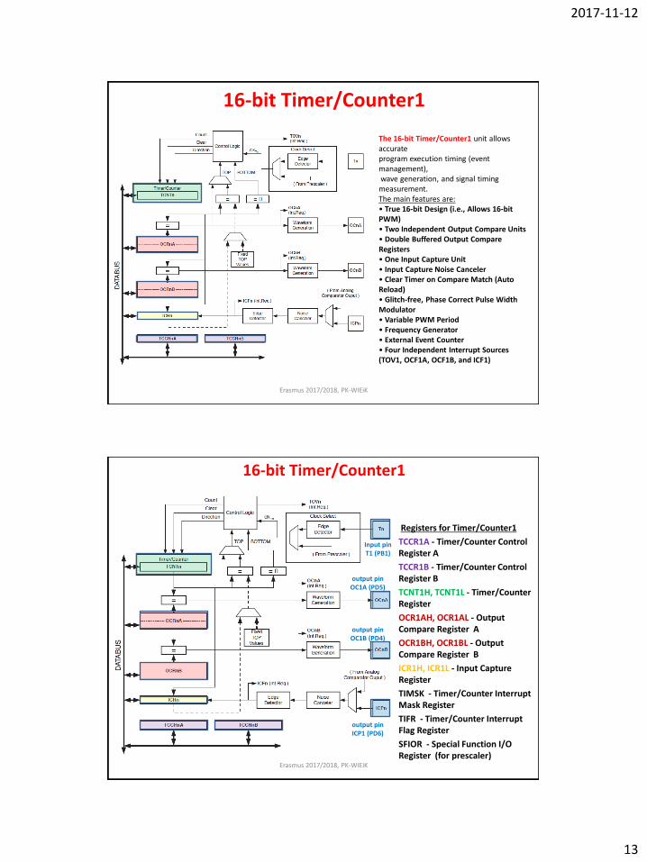
16-bit Timer/Counter1
The 16-bit Timer/Counter1 unit allows accurate program execution timing (event management), wave generation, and signal timing measurement. The main features are: • True 16-bit Design (i.e., Allows 16-bit PWM) • Two Independent Output Compare Units • Double Buffered Output Compare Registers • One Input Capture Unit • Input Capture Noise Canceler • Clear Timer on Compare Match (Auto Reload) • Glitch-free, Phase Correct Pulse Width Modulator • Variable PWM Period • Frequency Generator • External Event Counter • Four Independent Interrupt Sources (TOV1, OCF1A, OCF1B, and ICF1)
Erasmus 2017/2018, PK-WIEiK
16-bit Timer/Counter1
Registers for Timer/Counter1
• TCCR1A - Timer/Counter Control Register A
• TCCR1B - Timer/Counter Control Register B
• TCNT1H, TCNT1L - Timer/Counter Register
• OCR1AH, OCR1AL - Output Compare Register A
• OCR1BH, OCR1BL - Output Compare Register B
• ICR1H, ICR1L - Input Capture Register
• TIMSK - Timer/Counter Interrupt Mask Register
• TIFR - Timer/Counter Interrupt Flag Register
• SFIOR - Special Function I/O Register (for prescaler)
Input pin T1 (PB1)
output pin OC1A (PD5)
output pin OC1B (PD4)
output pin ICP1 (PD6)
Erasmus 2017/2018, PK-WIEiK
2017-11-12
14
Timers/counters in PC microprocessor system
Clock and Timer Circuits
• On the 80x86 architecture, the kernel must explicitly interact with several kinds of clocks and timer circuits .
• The clock circuits are used both to keep track of the current time of day and to make precise time measurements.
• The timer circuits are programmed by the kernel, so that they issue interrupts at a fixed, predefined frequency; such periodic interrupts are crucial for implementing the software timers used by the kernel and the user programs.
• All PC computers include:
– Real Time Clock (RTC), which is independent of the CPU and all other chips.
– Time Stamp Counter (TSC) which receives the clock signal of an external oscillator.
– Programmable Interval Timer (PIT) this device issues a special interrupt called timer interrupt, which notifies the kernel that one more time interval has elapsed.
– High Precision Event Timer (HPET) - provides a number of hardware timers that can be exploited by the kernel. Basically, the chip includes up to eight 32-bit or 64-bit independent counters
– ACPI Power Management Timer – (ACPI PMT) is yet another clock device included in almost all ACPI-based motherboards. Its clock signal has a fixed frequency of roughly 3.58 MHz.
Erasmus 2017/2018, PK-WIEiK
Top Related