


Languages
Pages
Legal


N O T I C E
THIS DOCUMENT HAS BEEN REPRODUCED FROM MICROFICHE. ALTHOUGH IT IS RECOGNIZED THAT
CERTAIN PORTIONS ARE ILLEGIBLE, IT IS BEING RELEASED IN THE INTEREST OF MAKING AVAILABLE AS MUCH
INFORMATION AS POSSIBLE
https://ntrs.nasa.gov/search.jsp?R=19810007193 2018-09-06T02:26:40+00:00Z
ESD-13530
OPTI'.AL MASS MEMORY SYSTEM
(AMM-13)
CONTRACT NUMBER NAS8-33687
AMM-13 SYSTEM SEGMENT SPECIFICATION
Reissue 2
(CDRL 005)
PREPARED FOR
GEORGE C. MARSHALL SPACE FLIGHT CENTER
NATIONAL AERONAUTICS AND SPACE ADMINISTRATION
MARSHALL SPACE FLIGHT CENTER (MSFC), ALABAMA 35812
NASA PROJECT ENGINEER: G. A. BAILEY
PHONE: (205) 453-1595
C
c
(NASA -Cii- I u I u^5) OPTICAL 6A:;S IEMIUji j ^Y31td INA(AMM - 13)!iVECIFILAZIUh (hdLLiS CUL,)., Ae1jjUl1Ljje,Fla. 1 12 p 11C A' 6 16F A6 1 CSC U913 J11cias
HARRIS CORPORATION Government information Systems DivisionRMIBPC) Box 94000 Melbourne, Florida 32901 • U S A • lei (305)727-S009

ESD-13530
OPTICAL MASS MEMORY SYSTEM
(AMM-13)
CONTRACT NUMBER NAS8-33687
AMM-13 SYSTEM SEGMENT SPECIFICATION
Reissue 2
(CDRL 005)
PREPARED FOR
GEORGE C. MARSHALL SPACE FLIGHT CENTER
NATIONAL AERONAUTICS AND SPACE ADMINISTRATION
MARSHALL SPACE FLIGHT CENTER (MSFC), ALABAMA 35812
NASA PROJECT ENGINEER: G. A. BAILEY
PHONE: (205) 453-1595
HARRIS CORPORATION
GOVERNMENT INFORMATION SYSTEMS DIVISION
P. 0. BOX 94000, MELBOURNE, FLORIDA 32901
29 OCTOBER 1980

JRi1R^ tall 0J1Ti O]liC2i!'i'ZaM
Reissue 1 10 Junt 1980 Editorial Changes - variou
26IMwa Z 21 Orr 19*O SV6Vv% ^1C,^1.1^{ipiAryq,fV AR^o^►f
JJ
AIIGM.
04
GNAL PAGE ISP(N11? ()UAI,ITN'
-' HARRIS CORPORATION sale COOT UM"Government Systems Group A 91417
I Melbourne DivisionsMelboume. Flom% 32901 11CALs
•wawa.9 t
i

AMM-13 SYSTEM SEGMENT SPECIFICATION
CDRL 005
REISSUE #2
29 OCTOBER 1980
APPROVAL:
APPROVAL:
HARRIS CORPORATION:
MSFC:
4
a
J
1
TABLE OF CONTENTS
PARAGRAPH TITLE PAGE
1.0 SCOPE ------------------------------------------ 1
2.0 APPLICABLE DOCUMENTS --------------------------- 1
2.1 Government Documents----------------------------- 1
2.2 MSFC/Harris Documents--------------------------- 1
2.3 Harris Documents-------------------------------- 1
2.4 Vendor Documents-------------------------------- 1
2.4.1 Digital Equipment Corporation ------------------ 2
2.4.2 AMPEX Corporation ------------------------------ 2
2.5 Standards--------------------------------------- 2
2.6 Other Reference Documents----------------------- 2
3.0 REQUIREMENTS ----------------------------------- 2
3.1 System Definition ------------------------------ 2
3.1.1 General Description ---------------------------- 4.
3.1.2 Mission ---------------------------------------- 5
3.1.3 Major Subsystem Listing ------------------------ E
3.1.4 System Diagrams--------------------------------- 7
3.1.4.1 Functional Flow Diagram ------------------------ g
3.1.4.2 Input Process Flow ------------------------------ 9
3.1.4.3 Output Process Flow ---------------------------- 11
3.1.4.4 System Block Diagram ---------------------------- 12
3.1.4.5 Subsystem Functional Allocation Charts --------- 13
3.1.4.5.1 Com;)uter Subsystem Functionali Allocation ------- 13
3.1.4.5.2 Software Subsystem Functional Ellocation ------- 14
3 1.4.5.3 Input Subsystem Functional Allocation ---------- 15
3.1.4.5.4 Recorder Subsystem Functional Allocation ------- 16
i
PAGE
z 3.1.4.5.5 Fiche Processor/Replicator Subsystem Functional
Allocation ----------------------------------------- 17
3.1.4.5.6 Verify Subsystem Functional Allocation ------------- 18
3.1.4.5.7 Storage and Retrieval Subsystem Functional
Allocation ----------------------------------------- 19
3.1.4.5.8 Output Subsystem Functional Allocation ------------- 20
3.1.4.5.9 Low Cost Reader Subsystem Functional Allocation ---- 21
3.1.4.6 Detailed System Block Diagrams --------------------- A
3.1.5 Interface Definition ------------------------------- 22
3.1.5.1 External Interfaces -------------------------------- 22
3.1.5.2 Internal Interfaces -------------------------------- 23
3.1.5.2.1 Computer and Software Subsystem Interfaces --------- 28
3.1.5.2.2 Intentionally Blank -------------------------------- 30
3.1.5.2.3 Input Subsystem Interfaces ------------------------- 30
3.1.5.2.4 Recorder Subsystem Interfaces ---------------------- 32
3.1.5.2.5 Fiche Processor/Replicator Subsystem Interfaces ---- 32
3.1.5.2.6 Verify Subsystem Interfaces ------------------------ 34
3.1.5.2.E Storage and Retrieval Subsystem Interfaces --------- 34
3.1.5.2.8 Output Subsystem Interfaces ------------------------ 35
3.1.5.2.9 Low Cost Reader Subsystem Interfaces --------------- 36
3.1.5.3 Facilities Interface ------------------------------- 36
3.1.6 Government Furnished Property List ----------------- 37
3.1.7 Operational and Organizational Concepts ------------ 37
3.1.7.1 Operational Concept -------------------------------- 37
3.1.7.2 Organizational Concepts ---------------------------- 37
3.2 Characteristics ------------------------------------ 38
3.2.1 Performance Characteristics ------------------------ 38
3.2.1.1 Data Storage Capacity ------------------------------ 38
ii

7-77
PAGE
3.2.1.1.1 Archival Storage Capacity ----------------------•---- 38
3.2.1.1.2 Non-Archival Storage Capacity ---------------------- 38
3.2.1.2 Access Time ----------------------------------------- 38
3.2.1.2.1 Access Time On-Line -------------------------------- 38
3.2.1.2.2 Access Time Off-Line ------------------------------- 39
3.2.1.3 Data Transfer Rate --------------------------------- 39
3.2.1.3.1 Data Transfer, Simultaneous Record and Read -------- 39
3.2.1.3.2 Dats Transfer, Multiple Readers -------------------- 39
3.2.1.4 Bit Error Rate (BER) ------------------------------- 39
3.2.1.5 Dn-Line Verification ------------------------------- 39
3.2.1.6 Recording Medium ----------------------------------- 40
3.2.1.1 Archivability -------------------------------------- 40
3.2.1.8 Record Handling ------------------------------------ 40
3.2.1.9 Replication ---------------------------------------- 41
3.2.1.10 System Control/Status ------------------------------ 41
3.2.1.11 Operators ------------------------------------------ 41
3.2.1.12 File Management System ----------------------------- 42
3.2.2 Physical Characteristics --------------------------- 43
3.2.2.1 Storage and Retrieval Subsystem -------------------- 43
3.2.2.2 Recorder Subsystem --------------------------------- 43
3.2.2.3 Other Subsystems------------------------------------ 43
3.2.2.4 Accessibility ------------------------------------- 43
3.2.3 Reliability --------------------------------------- 43
3.2.4 Maintainability ----------------------------------- 43
3.2.5 Availability -------------------------------------- 43
3.2.6 Environmental Conditions -------------------------- 43
3.2.6.1 Environmental Conditions, Non-Operating ----------- 44
3.2.6.2 Environmental Conditions, Operating --------------- 44
i i i

PAGE
3.3 Design and Construction ------------------------- 44
3.3.1 Materials. Processes. and Parts ----------------- 44
3.3.2 Electromagnetic Compatibility ------------ ------- 45
3.3.3 Identification and Marking ---------------------- 45
3.3.4 Workmanship -------------------------------------- 45
3.3.4.1 General ----------------------------------------- 45
3.3.5 Interchangeability ---------••-------------------- 45
3.3.6 Safety ------------------------------------------ 45
3.3.6.1 Grounds ----------------------------------------- 45
3.3.7 Human Performance/Human Engineering ------------- 46
3.3.8 Computer Resources ------------------------------ 46
3.3.8.1 Computer Programming ---------------------------- 46
3.3.8.2 Computational Components ------------------------ 47
3.3.8.2.1 Computational Cowponent Requirements ------------ 47
3.4 Documentation ----------------------------------- 47
3.4.1 Specifications ---------------------------------- 47
3 .4.2 Plans --------------- ---------------------------- 48
3.4.2.1 Engineering Test Plan --------------------------- 48
3.4.2.2 Installation Plan ------------------------------- 48
3.4.2.3 Training Plan ----------------------------------- 48
3.4.3 Procedures ------------------------------------- 48
3.4.3.1 Acceptance Test Procedure ----------------------- 48
3.5 Logistics -------------------------------------- 48
3.5.1 Maintenance ------------------------------------- 48
3.5.2 Supply ------------------------------------------ 48
3.5.3 Facilities and Facility Equipment --------------- 48
3.6 Training ---------------------------------------- 48
iv
m
PAGE
3.7 Functional Area Characteristics ------------------ 49
3.7.i Computer Subsystem Functional Characteristics ---- 49
3.7.1.1 Triport Information Exchange --------------------- 49
3.7.1.2 Indices File ------------------------------------ 49
3.7.1.3 Software Memory ----------------•------------------ 51
3.7.1.4 Subsystem Command/Control/Status Lines ----------- 51
3.7 1.5 Data Transfer links ------------------------------ 51
3.7.1.6 Data I/O Buffering ------------------------------ 52
3.7.1.7 Operator Interaction ----------------------------- 52
3.7.1.8 Small Record Staging ----------------------------- 52
3.7.1.9 Internal Status ---------------------------------- 52
3.7.1.10 Equipment List ---------------------•-------------- 52
3.7.2 Software Subsystem Functional Characteristics---- 53
3.7.2.1 Supervise and Monitor Resources ------------------ 53
3.7.2.2 Peripheral Handlers ------------------------------ 55
3.7.2.3 File Management, Staged Records ----------------- 55
3.7.2.4 File Management, Archived Records----------------- 55
3.7.2.5 Test and Status ---------------------------------- 55
3.7.2.6 Data Request Interpreter ------------------------- 57
3.7.2.7 Verification Assessment -------------------------- 57
3.7.2.8 Data Routing ------------------------------------ 57
3.7.2.9 I/O Priority ------------------------------------- 57
3.7.2.10 AMPEX Formatting --------------------------------- 57
3.7.3 Input Subsystem Functional Characteristics ------- 58
3.7.3.1 DBMS Port Data Ingest Control -------------------- 58
3.7.3.2 High Speed Data Ingest Clock --------------------- 58
3.7.3.3 Small vs. Large Record Determination;------------- 58
3.7.3.4 Small Record Extraction -------------------------- 58
V
PAGE
3.7.3.5 Large Record Headers ------------------------------ 58
3.7.3.6 AMPEX High Speed Data Ingest ------ - --------- ------ 60
3.7.3.7 AMPEX High Speed Data Output to Recorder
Subsystem ----------------------------------------- 60
3.7.3 8 AMPEX High Speed Data Output to Verify
Subsystem ----------------------------------------- 60
3.7.3.9 AMPEX High Speed Data Output to Output Subsystem--- 60
3.7.3.10 Internal Status ----------------------------------- 60
3.7.4 Recorder Subsystem Functional Characteristics ----- 60
3.7.4.1 Hign Speed Data Ingest Control -------------------- 62
3.7.4.2 High Speed Data Ingest Clock ---------------------- 62
3.7.4.3 Record Data On Photographic Film ------------------ 62
3.7.4.4 Fiche Loading/Unloading --------------------------- 63
3.7.4.5 Internal Status ----------------------------------- 63
3.7.5 Fiche Processor/Replicator Functional
Characteristics ----------------------------------- 63
3.7.5.1 Fiche Loading/Unloading --------------------------- 63
3.7.5.2 Fiche Processing ------- - -------------------- ------ 63
3.7.5.3 Replication --------------------------------------- 66
3.7.6 Verify Subsystem Functional Characteristics ------- 66
3.7.6.1 High Speed Data Ingest Control -------------------- 66
3.7.6.2 Bit-by-Bit Comparison ----------------------------- 66
3.7.6.3 Comparison Results -------------------------------- 66
3.7.7 Storage and Retrieval Subsystem Functional
Characteristics ----------------------------------- 66
3.7.7.1 Fiche Loading/Unloading --------------------------- 66
3.7.7.2 Fiche Storage ------------------------------------- 68
3.7.7.3 Fiche Pack Loading -------------------------------- 68
vi

PAGE
3.7.7.4 Retrieval and Reading ----------------------------- 68
3.7.7.5 High Speed Data Output Control -------------------- 68
3.7.7.6 High Speed Data Output ---------------------------- 69
3.7.7.7 Internal Status ----------------------------------- 70
3.7.8 Output Subsystem Functional Characteristics ------- 70
3.7.8.1 DBMS Port Data Output Control --------------------- 70
3.7.8.2 DBMS Port Data Outp ,it Clock ----------------------- 70
3.7.8.3 Oata Transfer to DBMS Port ------------------------ 70
3.7.8.4 Data Exchange with Computer Subsystem ------------- 70
3.7.8.5 High Speed Data Output to Verify Subsystem -------- 72
3.7.8.6 Internal Status ----------------------------------- 72
3.7.9 Low Cost Reader Subsystem Functional
Characteristics ----------------------------------- 72
3.7.9.1 Data Output Control ------------------------------- 72
3.7.9.2 Data Transfer ------------------------------------- 74
3.7.9.3 Fiche Loading/Unloading --------------------------- 74
3.7.9.4 Reading ------------------------------------------- 74
3.7.9.5 Data Buffering for Local Display ------------------ 74
3.7.9.6 Alphanumeric Display ------------------------------ 75
3.7.9.7 Operator Interface, Keyboard ---------------------- 75
3.1.9.8 Internal Status ----------------------------------- 75
4.0 QUALITY ASSURANCE PROVISIONS ---------------------- 75
4 .1 General ------------------------------------------- 75
4.1.1 Respons'.bility for Tests--------------------------- 76
4.1.2 Special Tests and Examinations -------------------- 76
4.2 Quality Conformance ------------------------------- 76
vii
PAGE
5.0 PREPARATION FOR DELIVERY -------------------------- 85
6.0 NOTES --------------------------------------------- 85
6.1 Glossary of Terms --------------------------------- 85
ATTACHMENT A Detailed System Block Diagrams
viii

1.0 SCOPE
This specification establishes the performance, design,
development, and test requirements for an Optics, Mass Memory System
prototype, hereinafter referred to as AMM-13. This system interfaces
to other system segments of the NASA End-to-End Data System (NEEDS) via
the Data Base Management System (DBMS) segment.
2.0 APPLICA9t.E DOCUMENTS
The following documents form a part of this specification to
the extent specified herein. In the event of conflict between the docu-
ments referred herein and the contents of this specification, this spec-
ification shall govern.
2.1 Government Documents
Contract NAS8-33687 - Statement of Work
Low Cost Reader - Statement of Work(1)
2.2 MSFC/Harris Documents
AMM/DBMS Interface Control Document, Reissue 2 Dated 29 Oct. 1984
2.3 Harris Documents
AMM-13 Subsystem Specifications
2.4 Vendor Documents
(1) The Low Cost Reader is included in this Specification for completeness.It is not presently included in the contract scope.
1
i
2.4.1 Digital Equipm
1 QE 001-GS
AA-D025A-TE
DEC Peripheral
DEC Installati
ent Corporation (DEC)
VAX/VMS Operator and Software
Documentation Kit
Operators Guide
Manuals (As appropriate)
on Guide
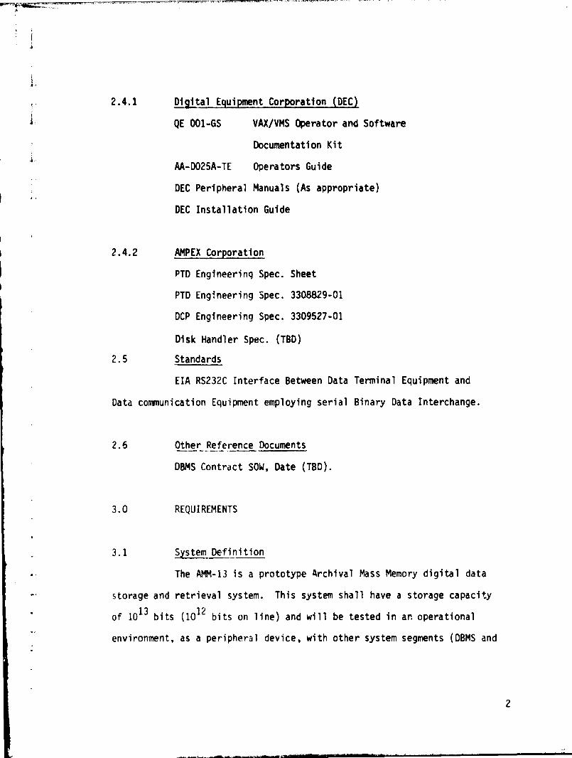
2.4.2 AMPEX Corporation
PTD Engineering Spec. Sheet
PTD Engineering Spec. 3308829-01
DCP Engineering Spec. 3309527-01
Disk Handler Spec. (TBD)
2.5 Standards
EIA RS232C Interface Between Data Terminal Equipment and
Data communication Equipment employing serial Binary Data Interchange.
2.5 Other Reference Documents
DBMS Contract SOW, Date (TBD).
3.0 REQUIREMENTS
3.1 System Definition
The AMM-13 is a prototype Archival Mass Memory digital data
storage and retrieval system. This system shall have a storage capacity
of 10 13 bits (10 12 bits on line) and will be tested in an operational
environment, as a peripheral device. with other system segments (DBMS and
2
s
CMS). The AMM-13 design and function will be compatible with the require-
ments of future similar systems with capacities of 10 15 bits such that no
technique or technology used shall preclude expandability to 1015 bits.
The AMM-13 shall provide the necessary computer, resident
software, and electro-optical devices necessary to record, verify, and
retrieve the optically stored digital data from an archival data base.
The stored data will be transferred to another system segment (DBMS/CMS)
for distribution to the ultimate user.
a
3
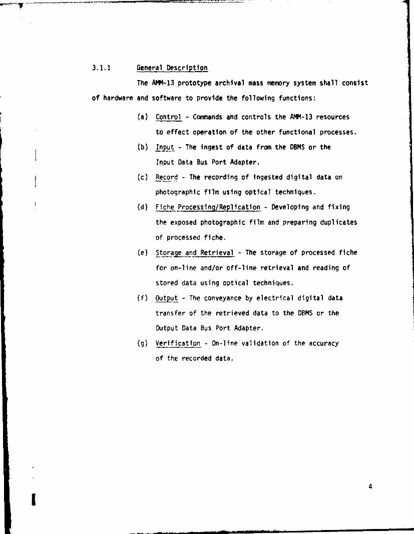
3.1.1 General Description
The AMM-13 prototype archival mass memory system shall consist
of hardware and software to provide the following functions:
(a) Control - Commands and controls the AMM-13 resources
to effect operation of the other functional processes.
(b) 1pput - The ingest of data from the DBMS or the
Input Data Bus Port Adapter.
(c) Record - The recording of ingested digital data on
photographic film using optical techniques.
(d) Fiche Processing/Replication - Developing and fixing
the exposed photographic film and preparing duplicates
of processed fiche.
(e) Storage and Retrieval - The storage of processed fiche
for on-line and/or off-line retrieval and reading of
stored data using optical techniques.
(f) Output - The conveyance by electrical digital data
transfer of the retrieved data to the DBMS or the
Output Data Bus Port Adapter.
(g) Verification - On-line validation of the accuracy
of the recorded data.
4
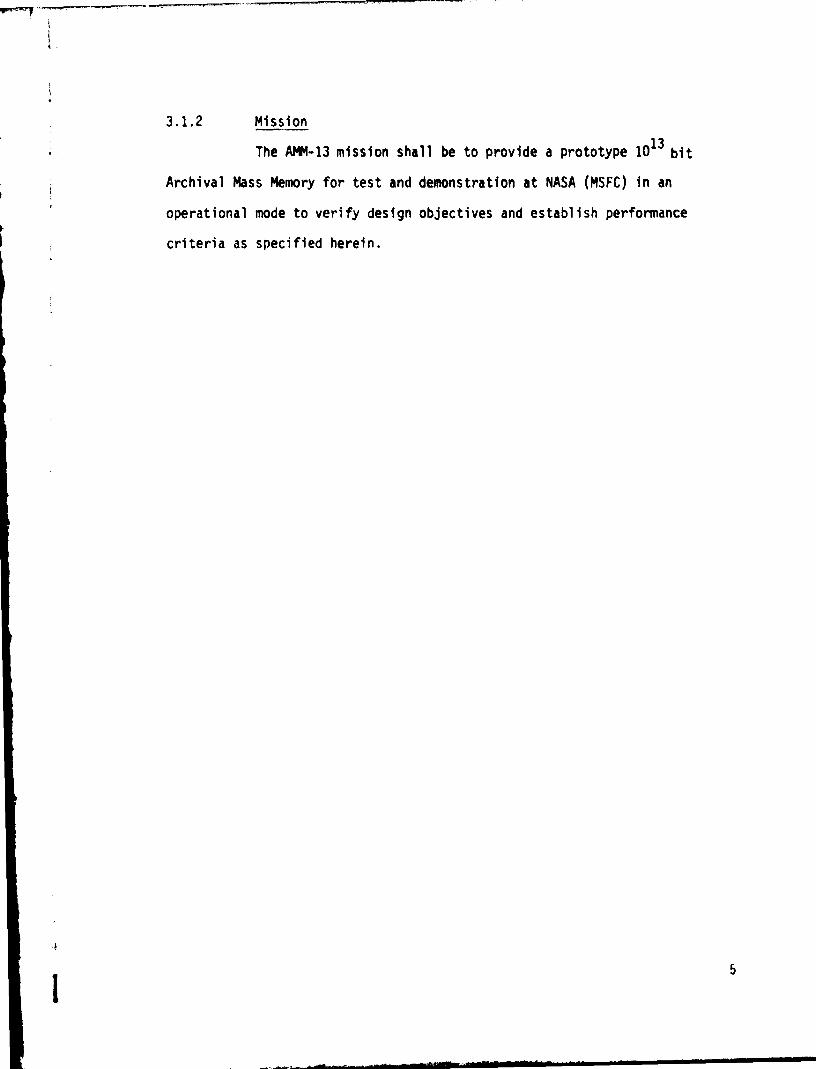
3.1.2 Mission
The AMM-13 mission shall be to provide a prototype 10 13 bit
Archival Mass Memory for test and demonstration at NASA (MSFC) in an
operational mode to verify design objectives and establish performance
criteria as specified herein.
5
iii
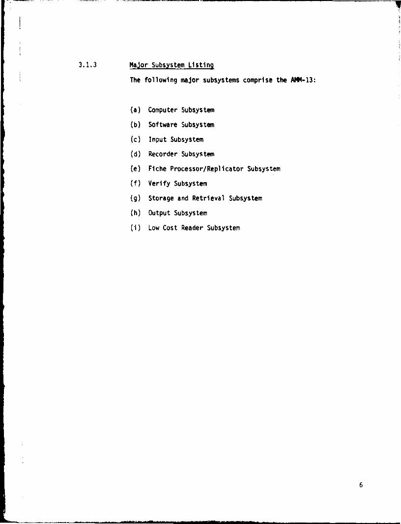
3.1.3 Major Subsystem Listing
The following major subsystems comprise the AMM-13:
(a) Computer Subsystem
(b) Software Subsystem
(c) Input Subsystem
(d) Recorder Subsystem
(e) Fiche Processor/Replicator Subsystem
(f) Verify Subsystem
(g) Storage and Retrieval Subsystem
(h) Output Subsystem
(i) Low Cost Reader Subsystem
6
i
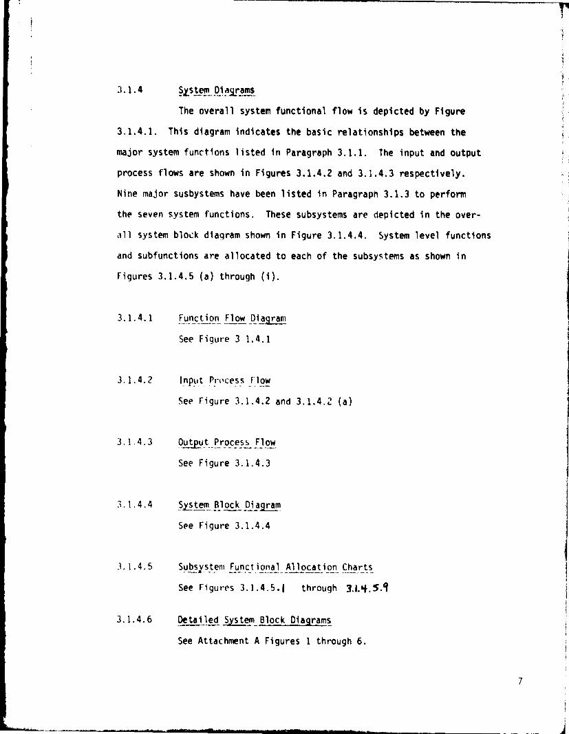
3.1.4 System, Diagrams
The overall system functional flow is depicted by Figure
3.1.4.1. This diagram indicates the basic relationships between the
major system functions listed in Paragraph 3.1.1. The input and output
process flows are shown in Figures 3.1.4.2 and 3.1.4.3 respectively.
Nine major subbystems have been listed in Paragraph 3.1.3 to perform
the seven system functions. These subsystems are depicted in the over-
all system block diagram shown in Figure 3.1.4.4. System level functions3
and subfunctions are allocated to each of the subsystems as shown in
Figures 3.1.4.5 (a) through (i).
3.1.4.1 Function Flow Diagram
See Figure 3 1.4.1
3.1.4.2 Input. Process Flow
See Figure 3.1.4.2 and 3.1.4.2 (a)
3.1.4.3 Output_Process Flow
See Figure 3.1.4.3
3.1.4.4 System_Block Dia ram
See Figure 3.1.4.4
3.1.4.5 Subsystem Functional Allocation Charts
See Figures 3.1.4.5.E through
3.1.4.6 Detailed System Block Diagrams
See Attachment A Figures 1 through 6.
7

Qcc
Q
30JLLJ
Z0
x
m
LL
cl;i7O^

fa
oWr!W i
cc
N ; _
rwyW
c^t0OuWars0Y.rZW2
OW V ugagW
W
s=W Wcc
rtwri
a°
N
WN ^ t
cW .I
ti
Its
N^`^W
ac O W CV5a
MA
O ^ yH W
yvs can
V) g=^^t t O^• w W
^ NWt7 yyi7
I
me atLipW
0ac
yw
LL ` ycc
w^Oado
C^lot
m
W r c O
^VO W°^ C3
WN i. f
CLO
G
Wd ts0.de
yN cc W
Q OvN CL
V^Q Sv yt ° G w
Z iO u.rLJ
WoV
mm Wy QViS
TN
O S
a u W c c^W
acdf C3d 4c W i
Wcc
cc
Jt
^O M =
N O O cy^ O y
i W KiNC
C 49i W r
iV
i d OW O N r 0WC
4A CL it Z =dr
O
t3OW
Q O ^v^ra
W W
W t =Wit
W49
cc
N ^
NI WW ^uc^C6
N
d
U_

•r
MOD
NN r
et
rN 4n
r t 4
M mOr M
N
ti
M
toN
N m %n
W V
d 4 ^"^
M 4 NN { ^
CA ac
W0dN ICCOpp u^ 000 ¢vW r'~o u i ^ may.. o s&M ^Wm
i Wa_ = t y
"d``i ^2 m O m o
Z
O vIc
WJ
0
z
WaZCO)r
Q
/O
NV
C)
GJL
lU

W ^^
d H H V. W^OOd =GoW OO
O ~ N Z^ Z y W i WZZ ^ ZCC
r
< O ZZ SV
IL " S OWO Z
4 Z^390O ^, VN O
4 d41 CD t _
wWH
Z0
30J
WV0ccIL
a
0T
1
a
W yZ ^Z
W O1- H VW N O
NI..
a NW^ Wu= = No OQ
0
0 dcoe
H W< wIL0I-.co^°C,.^i
Z W Wza
O OMN
ZW O > O to
W_ t c Q w^ < w Z OH WuhZ O m w
O
N ^ Z^ m Q ^ N
031^Q W
t Q H OO O WZ O O
Lid W ` 0 mLfij O
Lm cc C W Wp'0CCZ Z ^
WW _O =CL
H
W..r000Z
ccW d
N
Q
^. ` V^ O ^ d0
M
rMa.^i.7

AMM-13 SYSTEM BLOCK DIAGRAMDBMS DATA
BUS PORT DBMS DATA
ADAPTER TRIPORT BUS PORTMEMORY ADAPTER
COMPUTER
SOFTWARE
SUBSYSTEM
SUBSYSTEM
INPUT
s
OUTPUTSUBSYSTEM SUBSYSTEM
LOW COST
READER
SUBSYSTEM
VERIFY SUBSYSTEM
FICHE STORAGE
RECORDER PROCESSOR/ ANDAND
SUBSYSTEM REPUCATOR pp, SUBSYSTEM SUBSYSTEM
„99. '
I i 1 .4.4
i

3.1.4.5.1 COMPUTER SUBSYSTEM FUNCTIONAL ALLOCATION
0 Exchange information with Triport Memory.
• House indices for File Manager.
0 House all resident operational and control software.
• Provide standard command/control/status interfaces to Input,
Recorder, Verify, Storage and Retrieval, Output, and Low
Cost Reader Subsystems.
• Provide standard data transfer interfaces to Input, Output, and
Low Cost Reader Sii.1systems.
• Buffer data as re;jired by the Software Subsystem.
• Provide an operator interface through the Computer Subsystem
operator console.
• Provide on-line disk storage for small record staging.
• Provide internal status information to the Software Subsystem.
Fiqure 3.1.4.5.1 13
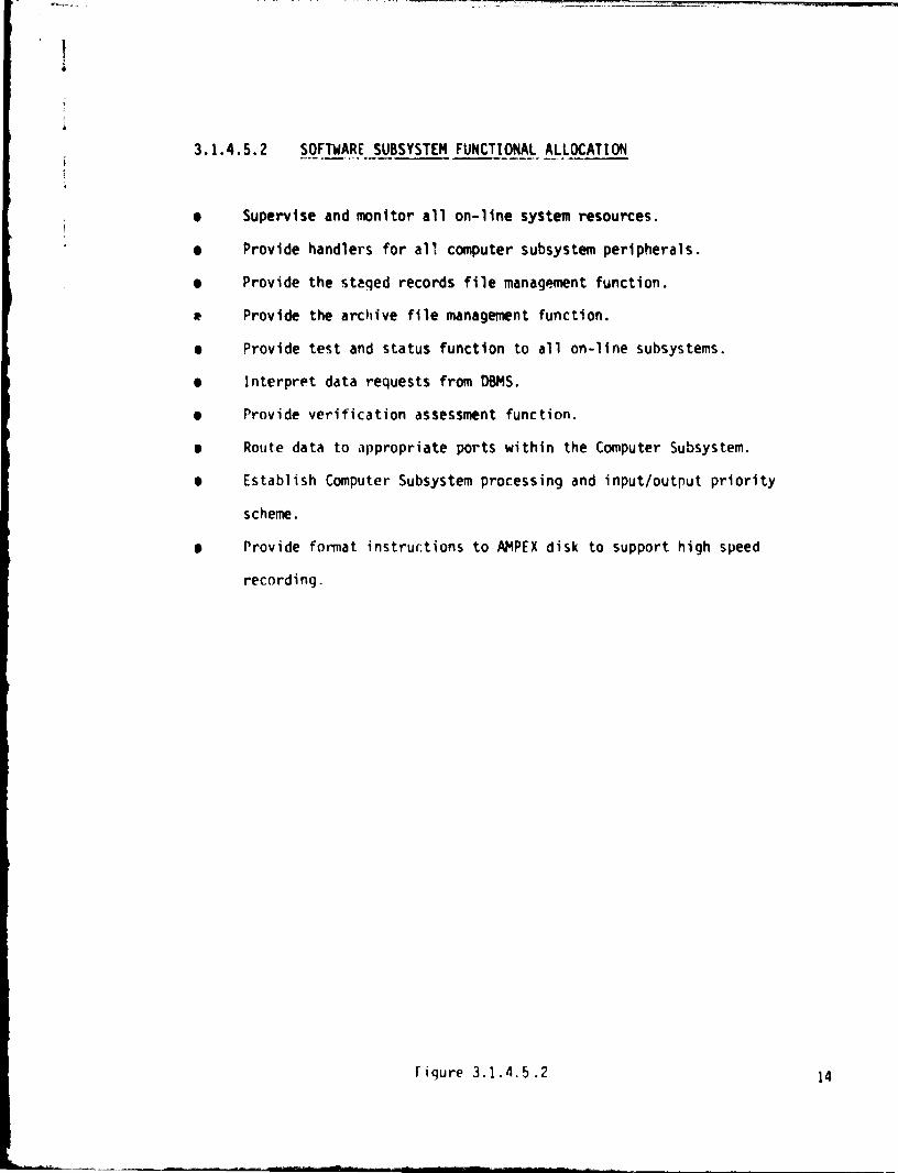
3.1.4.5.2 SOFTWARE SUBSYSTEM FUNCTIONAL ALLOCATION
• Supervise and monitor all on-line system resources.
0 Provide handlers for all computer subsystem peripherals.
• Provide the staged records file management function.
R Provide the archive file management function.
• Provide test and status function to all on-line subsystems.
6 Interpret data requests from DBMS.
0 Provide verification assessment function.
0 Route data to appropriate ports within the Computer Subsystem.
• Establish Computer Subsystem processing and input/output priority
scheme.
0 Provide format instructions to AMPEX disk to support high speed
recording.
Figure 3.1.4.5.2
14

3.1.4.5.3 INPUT SUBSYSTEM FUNCTIONAL ALLOCATION
• Exchange data transfer control information with DBMS high speed
port adapter.
• Provide clock to strobe data out of DBMS high speed port buffer.
e Make small vs. large record determination of input data stream.
• Extract small records and provide rate buffer to support transfer
to Computer Subsystem.
• Copy large record headers and provide rate buffer to support
transfer to Computer Subsystem.
• Provide data handling/buffering function to facilitate data
transfer to AMPEX high speed input port.
• Provide data handling/buffering function to facilitate data transfer
from AMPEX high speed output port to Re-n •der Subsystem.
• Provide data handling/buffering function to facilitate data transfer
from AMPEX high speed output port to Verify Suhsystem.
• Provide data handling/buffering function to facilitate data transfer
from AMPEX high speed output port to the Output Subsystem.
• Provide internal status information to the Software Subsystem.
Figure 3.1.4.5.3 15
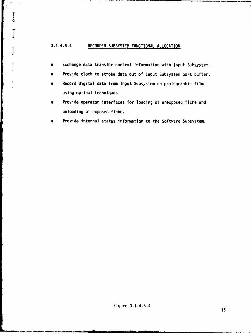
3.1.4.5.4 RECORDER SUBSYSTEM FUNCTIONAL ALLOCATION
• Exchange data transfer control information with Input Subsystem.
• Provide clock to strobe data out of Input Subsystem port buffer.
• Record digital data from Input Subsystem on photographic film
using optical techniques.
• Provide operator interfaces for loading of unexposed fiche and
unloading of exposed fiche.
• Provide internal status information to the Software Subsystem.
Figure 3.1.4.5.416
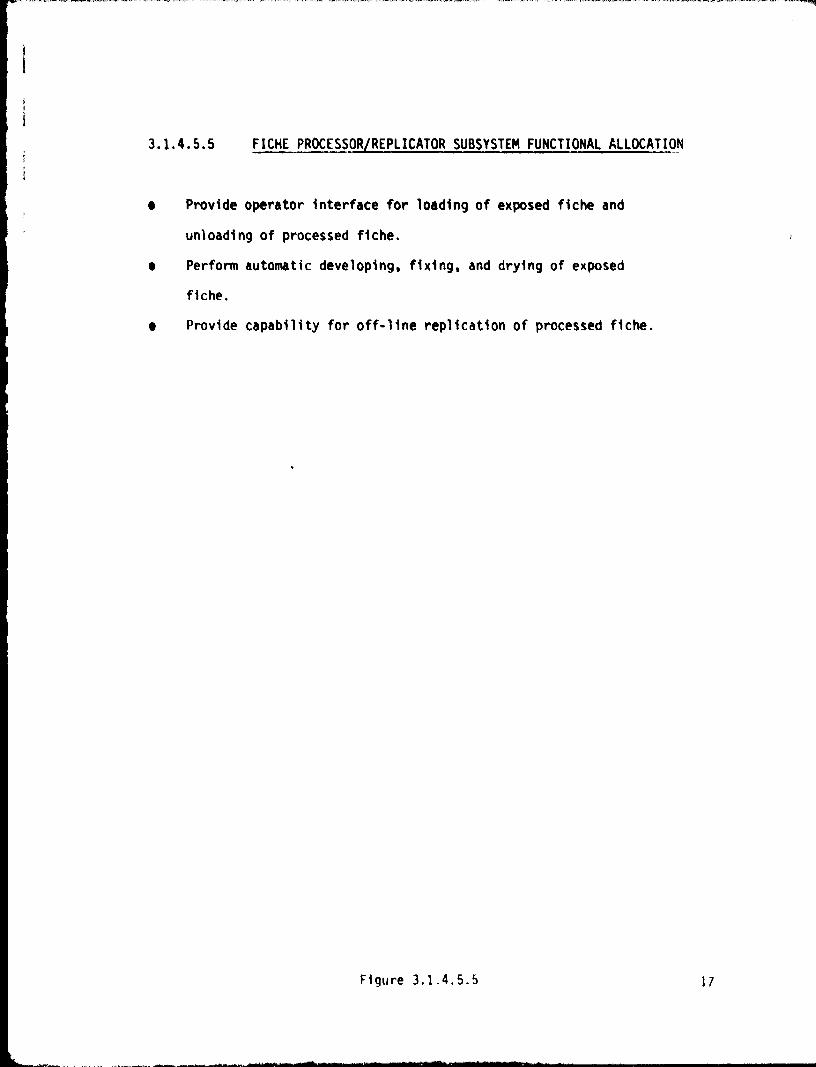
3.1.4.5.5 FICHE PROCESSOR/REPLICATOR SUBSYSTEM FUNCTIONAL ALLOCATION
• Provide operator interface for loading of exposed fiche and
unloading of processed fiche.
• Perform automatic developing, fixing, and drying of exposed
fiche.
• Provide capability for off-line replication of processed fiche.
Figure 3.1.4.5.5 17
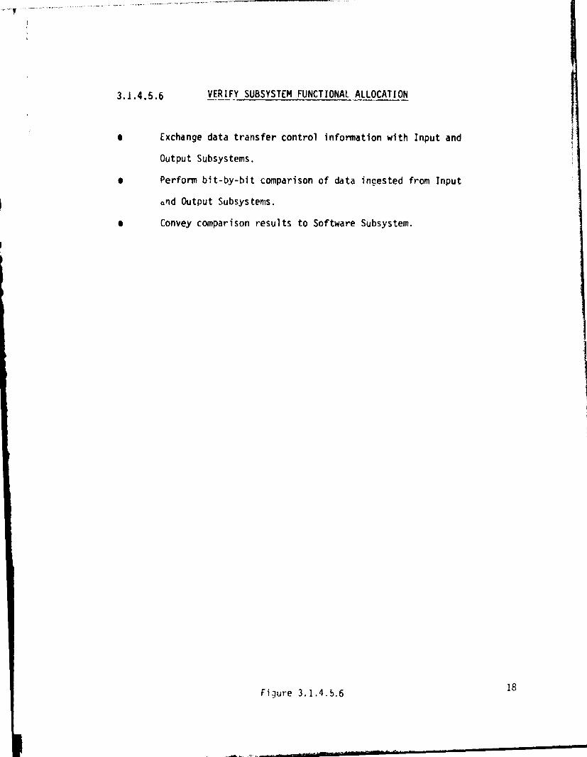
3.1.4.5.6 VERIFY SUBSYSTEM FUNCTIONAL_ ALLOCATION
• Exchange data transfer control information with Input and
Output Subsystems.
• Perform bit-by-bit comparison of data ingested from Input
and Output Subsystems.
• Convey comparison results to Software Subsystem.
Figure 3.1.4.5.618

3.1.4.5.7 STORAGE AND RETRIEVAL SUBSYSTEM FUNCTIONAL ALLOCATION
• Provide operator interface for loading of individual fiche into
fiche packs.
• Provide both on-line and off-line fiche pack storage.
• Provide operator interface for loading of fiche packs into on-line
ulits.
• Provide auta-natic retrieval and reading of original and/or replicated
fiche stored on-line.
• Provide internal status informatioo to the Software Subsystem.
• Exchange data transfer control information with Output Subsystem.
• Provide data handling/buffering function to facilitate data
transfer to the Output Subsystem.
• Provide clock to strobe data into Output Subsystem.
Figure 3.1.4.5.7 19

3.1.4.5.8 OUTPUT SUBSYSTEM FUNCTIONAL ALLOCATION
• Exchange data transfer control information with DBMS high speed
port adapter.
• Provide clock to strobe data into DMBS high speed port buffer.
• Provide data handling/buffering function to facilitate data transfer
to the DBMS high speed port adapter.
• Provide data handling/buffering function to facilitate data transfer
to the Computer Subsystem.
• Provide data handling/buffering function to facilitate data transfer
from the Storage and Retrieval Subsystem.
• Provide data handling function to facilitate data transfer to the
Verify Subsystem.
• Provide internal status information to Software Subsystem.
Figure 3.1.4.5.8 20
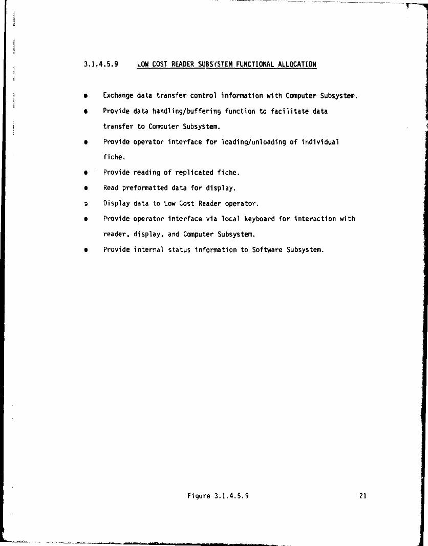
3.1.4.5.9 LOW COST READER SUBSYSTEM FUNCTIONAL ALLOCATIONst
3 e Exchange data transfer control information with Computer Subsystem.1
j e Provide data handling/buffering function to facilitate data
transfer to Computer Subsystem.
e Provide operator interface for loading/unloading of individual
fiche.
e ' Provide reading of replicated fiche.
e Read preformatted data for display.
Display data to Low Cost Reader operator.
e Provide operator interface via local keyboard for interaction with
reader, display, and Computer Subsystem.
e Provide internal status information to Software Subsystem.
Figure 3.1.4.5.9 21

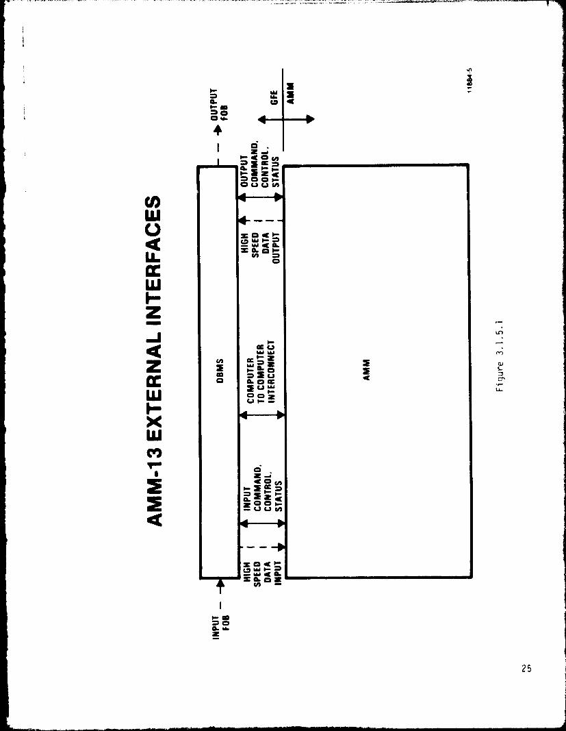
3.1.5 Interface Definition
3.1.5.1 External Interfaces
The external interfaces that control the flow of command,
control, status, and data between the AMM-13 and DBMS system segments
are depicted in Figure 3.1.5.1. Detailed definition of these inter-
faces are contained in the AMM/DBMS Interface Control Document (See
Section 2.0).
22

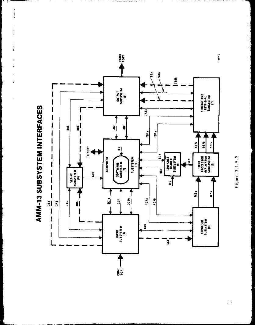
3.1.5.2 Internal Interfaces
The internal interfaces provide for information exchange
between the various ANM-13 Subsystems. Detailed definition of all
internal interfaces shall be contained in the Subsystem Specifications.
This section defines the system level functional requirements for each
internal interface. These interfaces are depicted in Figure 3.1.5.2
and labeled by general classification as follows:
(A) Hi_ch Speed Data Transfer Control
These interfaces shall control the high speed data
transfer ports. They shall include control lanes
to effect a logical data transfer across the high
speed interface.
(B) Hjkh Speed 13ta Transfer
These interfaces shall provide for high speed data
transfer between subsystems. All transfers shall
be unidirectional 32 bit parallel buffered 1/0
transfers. Logic levels shall be TTL compatible.
High speed data transfers shall be accomplished
with a bit error rate less than 10-10
(C) Low Speed Data Exchanje with CqTputer Subsystem
These interfaces shall provide data exchange with
the Computer Subsystem using standard logical
concepts via DEC DR-11B I/O ports.
(D) Cotivand/Control/Status Exchange
These interfaces shall be standard RS 232C inter-
connects to the Computer Subsystem via DEC DZ-11
I/O ports operating at 19.2K bits/sec.
23
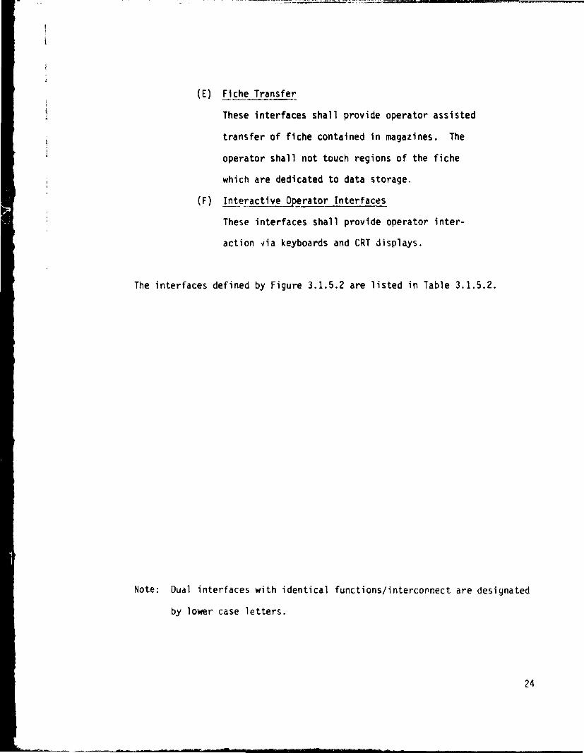
(E) Fiche Transfer
These interfaces shall provide operator assisted
transfer of fiche contained in magazines. The
operator shall not touch regions of the fiche
which are dedicated to data storage.
(F) Interactive Operator Interfaces
These interfaces shall provide operator inter-
action ria keyboards and CRT displays.
The interfaces defined by Figure 3.1.5.2 are listed in Table 3.1.5.2.
Note: Dual interfaces with identical functions/interconnect are designated
by lower case letters.
24
i1
N
`r
W
C7O ^
I Zrr t O y0 H O^ O O rO La W (A
W __
CCs r ^Q FE y O
pccWH-Z
J °` "Q W
W d ZM
z
cc
mCr O^aC)CL 0 cc
WodZ v^- ca r
XWMr o
t O ycr0 Z t
ZUUCAQ
0 4c r
S N p Z
r mO d4 ^Z
25
3
eg 3
WVaccW1-Z
W
U)
CD
wCO)rw
a
r-
I o
oil
a
°,as
NJ O
1In n r<i e
L
i7
iW-0
..I1
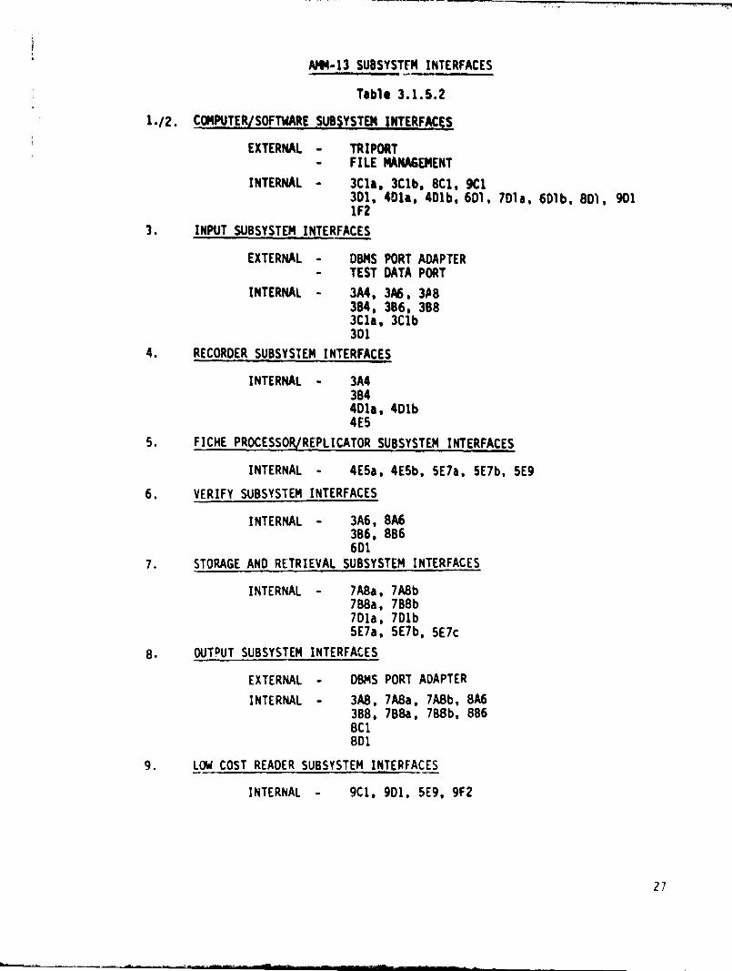
AMM-13 SUBSYSTEM INTERFACES
Table 3.1.5.2
1.12. COMPUTER/SOFTWARE SUBSYSTEM INTERFACES
EXTERNAL - TRIPORT
- FILE MANAGEMENT
INTERNAL - 3Cla, 3Clb, 8C1, 9C13D1. 401a. 401b, 6D1, 7Dla, 6DIb, 8D1, 9011F2
3. INPUT SUBSYSTEM INTERFACES
EXTERNAL - DBMS PORT ADAPTER
- TEST DATA PORT
INTERNAL - 3A4, 3A6, 3A8384, 386, 3883C1a, 3CIb301
4. RECORDER SUBSYSTEM INTERFACES
INTERNAL - 3A4384401x, 401b4E5
5. FICHE PROCESSORLREPLICATOR SUBSYSTEM INTERFACES
INTERNAL - 4E5a, 4E5b, 5E1a, 5E7b, 5E9
6. VERIFY SUBSYSTEM INTERFACES
INTERNAL - 3A6, 8A6366. 8B6601
7. STORAGE AND RETRIEVAL SUBSYSTEM INTERFACES
INTERNAL - 7A8a, 7A8b7B8a, 7B8b7D1a, 7Dlb5E7a, 5E7b, 5E7c
8. OUTPUT SUBSYSTEM INTERFACES
EXTERNAL - DBMS PORT ADAPTER
INTERNAL - 3A8, 7ABa, 7A8b, 8A6388, 7B8a, 7B8b, 8B68C18D1
9. LOW COST READER SUBSYSTEM INTERFACES
INTERNAL - 9C1. 9D1, 5E9, 9F2
27

3.1.5.2.1 Computer and Software Subsystem Interfaces
In addition to the definitions of these interfaces contained
in Paragraphs 3.1.5.1 and 3.1.5.2, Figure 3.1.5.2, and Table 3.1.5.2, the
following system level provisions shall be adhered to:
3Cla: This interface shall provide for the transfer
of small records and large record headers from
the Input Subsystem to the Computer Subsystem.
3C1b: This interface shall provide for the transfer
of small records staged on the RM05 disk to
the AMPEX disk for subsequent recording.
8C1: This interface shall provide for the transfer
of requested data staged in the Output Subsystem
to the Computer Subsystem. It shall provide
for the transfer of requested data staged in
the Computer Subsystem to the Output Subsystem.
9C1: This interface shall provide for the transfer of
requested data from the Low Cost Reader Subsystem
to the Computer Subsystem.
3D1: This interface shall provide command/control/
status information exchange betweer the Computer
Subsystem and the Input Subsystem.
Qla: This interface shall provide command/control/
status information exchange between the Computer
Subsystem and Recorder N1 in the Recorder Subsystem.
28

401b: This interface shall provide command/control
status information exchange between the
Computer Subsystem and Recorder #2 in the
Recorder Subsystem.
6D1: This interface shall provide command/control/
status information exchange between the
Computer Subsystem and the Verify Subsystem.
Specifically, the Verify Subsystem shall send
results of bit-by-bit verification function via
this interface.
701a: This interface shall provide command/control/
status information exchange between the
Computer Subsystem and S & R Unit 01 in the
Storage and Retrieval Subsystem.
7Dlb: This interface shall provide command/control/
status information exchange between the
Computer Subsystem and S & R Unit M2 in the
Storage and Retrieval Subsystem.
801: This interface shall provide command/control/
status information exchange between the
Computer Subsystem and the Output Subsystem.
9D1: This interlace shall provide command/control/
status information exchange between the
Computer Subsystem and the Low Cost Reader Sub-
system. In addition, it shall serve as a
conmunications link for the Low Co-A Reader Sub-
system keyboard/display terminal. This link shall
be a standard computer terminal link.
29
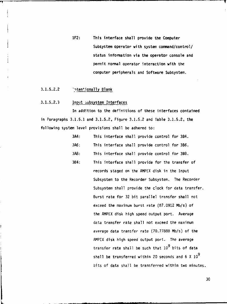
1F2: This interface shall provide the Computer
Subsystem operator with system command/control/
status information via the operator console and
permit normal operator interaction with the
computer peripherals and Software Subsystem.
3.1.5.2.2 "nten*.ionally Blank
3.1.5.2.3 Input subsystem Interfaces
In addition to the definitions of these interfaces contained
in Paragraphs 3.1.5.1 and 3.1.5.2, Figure 3.1.5.2 and Table 3.1.5.2, the
following system level provisions shall be adhered to:
3A4: This interface shall provide control for 3B4.
3A6: This interface shall provide control for 3B6.
3A8: This interface shall provide control for 3B8.
3B4: This interface shall provide for the transfer of
records staged on the AMPEX disk in the Input
Subsystem to the Recorder Subsystem. The Recorder
Subsystem shall provide the clock for data transfer.
Burst rate for 32 bit parallel transfer shall not
exceed the maximum burst rate (87.0912 Mb/s) of
the AMPEX disk high speed output port. Average
data transfer rate shall not exceed the maximum
average data transfer rate (70.77888 Mb/s) of the
AMPEX disk high speed output port. The average
transfer rate shall be such that 10 9 bits of data
shall be transferred within 20 seconds and 6 X 10⁹
bits of data shall be transferred within two minutes.
30
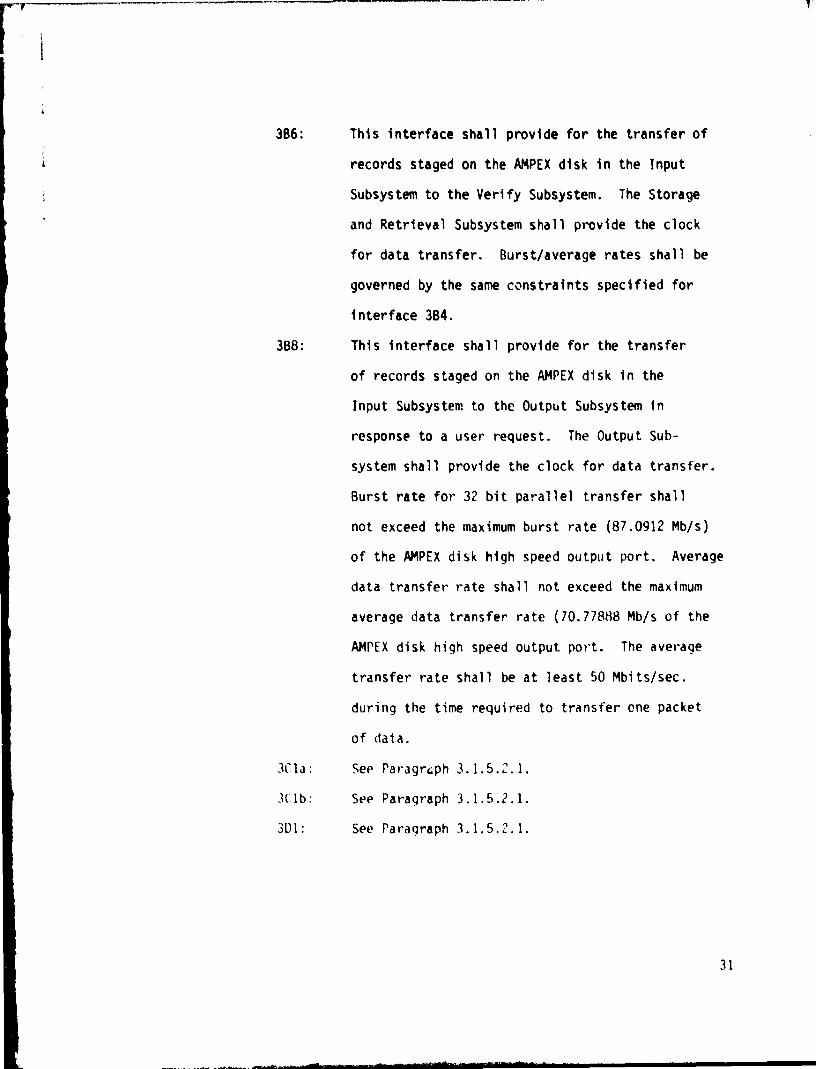
3B6: This interface shall provide for the transfer of
records staged on the AMPEX disk in the Input
Subsystem to the Verify Subsystem. The Storage
and Retrieval Subsystem shall provide the clock
for data transfer. Burst/average rates shall be
governed by the same constraints specified for
interface 3B4.
3B8: This interface shall provide for the transfer
of records staged on the AMPEX disk in the
Input Subsystem to the Output Subsystem in
response to a user request. The Output Sub-
system shall provide the clock for data transfer.
Burst rate for 32 bit parallel transfer shall
not exceed the maximum burst rate (87.0912 Mb/s)
of the AMPEX disk high speed output port. Average
data transfer rate shall not exceed the maximum
average data transfer rate (10.77888 Mb/s of the
AMPEX disk high speed output port. The average
transfer rate shall be at least 50 Mbits/sec.
during the time required to transfer one packet
of data.
3i la : See Paragraph 3.1.5..1.
3C1b: See Paragraph 3.1.5.2.1.
3D1: See Paragraph 3.1.5.2.1.
31
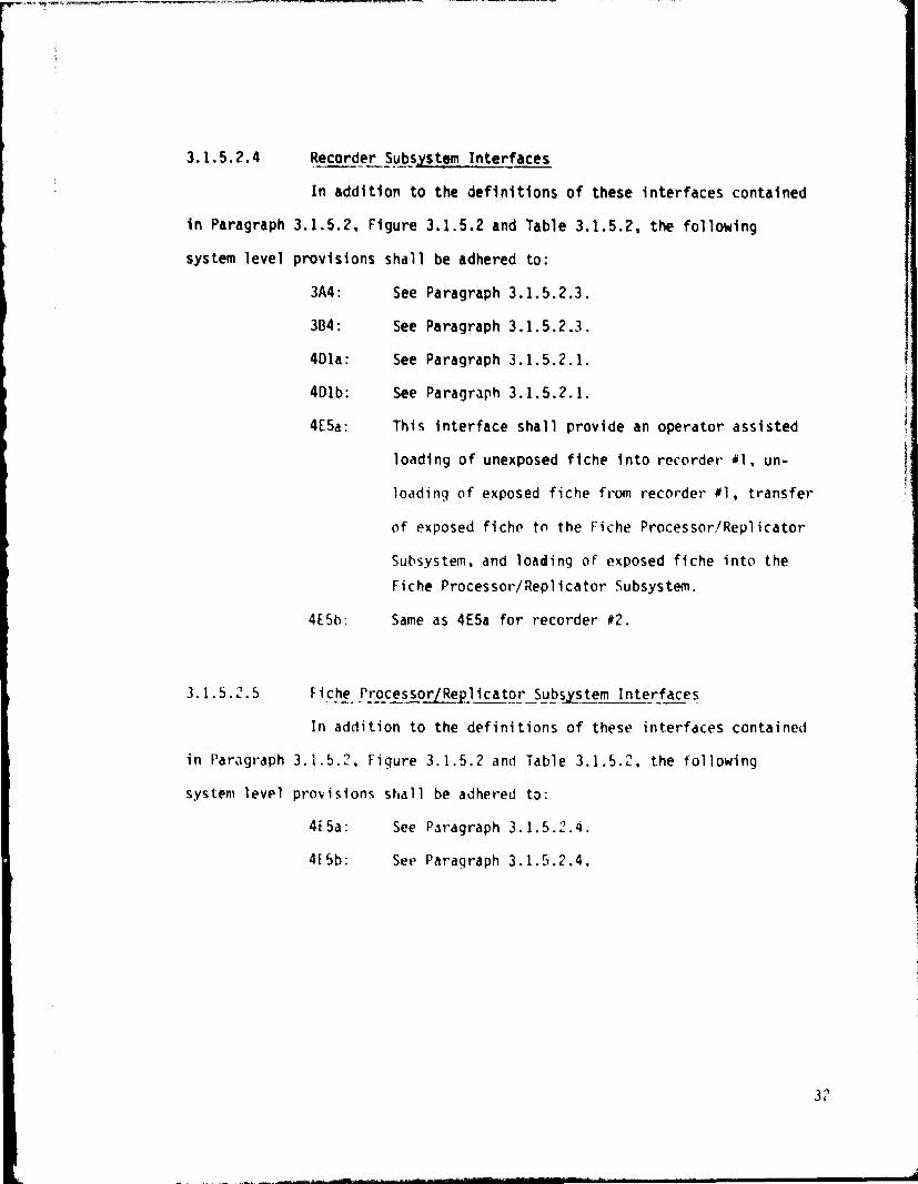
3.1.5.2.4 Recorder Subsystem Interfaces
In addition to the definitions of these interfaces contained
in Paragraph 3.1.5.2, Figure 3.1.5.2 and Table 3.1.5.2, the following
system level provisions shall be adhered to:
3A4: See Paragraph 3.1.5.2.3.
3D4: See Paragraph 3.1.5.2.3.
Qla: See Paragraph 3.1.5.2.1.
Olb: See Paragraph 3.1.5.2.1.
4E5a: This interface shall provide an operator assisted
loading of unexposed fiche into recorder 01, un-
loading of exposed fiche from recorder 01, transfer
of exposed fiche to the Fiche Processor/Replicator
Subsystem, and loadin g of exposed fiche into the
Fiche Processor/Replicator Subsystem.
4E5b: Same as 4E5a for recorder #2.
3.1.5.2.5 Fiche Processor Re licator Subsystem Interfaces
In addition to the definitions of these interfaces contained
in Paragraph 3.1.5.2, Figure 3.1.5.2 and Table 3.1.5.2, the following
system level provisions shall be adhered to:
45a: See Paragraph 3.1.5.2.4.
415b: See Paragraph 3.1.5.2.4.
32

5E7a: This interface shall provide an operator
assisted unloading of processed (and/or
replicated) fiche from the Fiche Processor/
Replicator Subsystem, transfer of the fiche to
and loading into S&R Unit N1 in the Storage and
Retrieval Subsystem.
5E7b: Same as 5E7a for SO Unit 02.
5E7c: This interface shall provide an operator
assisted unloadin; of processed (and/or
replicated) fiche from the Fiche Processor/
Replicator Subsystem, transfer of the fiche
to and loading into the fiche packs residing
in off-line storage in the Storage and Retrieval
Subsystem.
5E9: This interface shall provide an operator assisted
unloading of processed fiche from the Fiche
Processor/Replicator Subsystem, transfer of the
fiche to and loading into the Low Cost Reader
Subsystem.
33
3.1.5.2.6 Verify Subsystem Interfaces
In addition to the definitions of these interfaces contained
in Paragraph 3.1.5.2, Figure 3.1.5.2, and Table 3.1.5.2, the following
system level provisions shall be adhered to:
3A6: See Paragraph 3.1.5.2.3.
8A6: See Paragraph 3.1.5.2.8.
3B6: See Paragraph 3.1.5.2.3.
8B6- See Paragraph 3.1.5.2.8.
6Q1: See Paragraph 3.1.5.2.1.
3.1.5.2.7 Storage and Retrieval Subsystem Interfaces
In addition to the definitions of these interfaces contained
in Paragraph 3.1.5.2, Figure 3.1.5.2 and Table 3.1.5.2, the following
system level provisions shall be adhered to:
7A8a: This interface shall provide control for 768a.
7A8b: This interface shall provide control for 7B8b.
7B8a: This interface shall provide for the transfer
of requested data from S & R Unit #1 in the
Storage and Retrieval Subsystem to the Output
Subsystem. The Storage and Retrieval Subsystem
shall provide the clock for data transfer. Burst
rate for 32 hit parallel transfer shall not exceed
the maximum burst rate of the S & R Unit high
speed output port. Average data transfer rate
shall not exceed the maximum average data transfer
rata of the S & R Unit high speed output port. The
average transfer rate shall be such that 10 9 bits of
data shall be transferred within 20 seconds.
34

7B8b: This interface is identical to 7B8a except
that it connects S b R Unit M2 to the Output
Subsystem.
Ma: See Paragraph 3.1.5.2.1.
7D1b: See Paragraph 3.1.5.2.1.
5E7a: See Paragraph 3.1.5.2.5.
5E7b: See Paragraph 3.1.5.2.5.
5E7c: See Paragraph 3.1.5.2.5.
3.1.5.2.8 OutLut_ Subsystem Interfaces
In addition to the definitions of these interfaces contained
in Paragraphs 3.1.5.1 and 3.1.5.2. Figure 3.1.5.2 and Table 3.'.5.2, the
following system level provisions shall be adhered to:
3AB: See Paragraph 3.1.5.2.3.
7A8a: See Paragraph 3.1.5.2.7.
7A8b: See Paragraph 3.1.5.2.7.
8A6: This interface shall provide control for 8B6.
3B8: See Paragraph 3.1.5.2.3.
7B8a: See Paragraph 3.1.5.2.7.
7B8b: See Paragraph 3.1.5.2.7
8B6: This interface shall provide for the transfer of
records from the Output Subsystem to the Verify
Subsystem. The Storage and Retrieval Subsystem
shall provide the clock for data transfer. Data
transfer shall by synchronous with interface 3B6.
8c1: See Paragraph 3.1.5.2.1.
SDI: See Paragraph 3.1.5.2.1.
35
3.1.5.2.9 Low Cost Reader Subsystem Interfaces
In addition to the definitions of these interfaces contained
in Paragraph 3.1.5.2, Figure 3.1.5.2 and Table 3.1.5.2, the following
system level provisions shall be adhered to:
9C1: See Paragraph 3.1.5.2.1
9D1: See Paragraph 3.1.5.2.1.
5E9: See Paragraph 3.1.5.2.5.
9F2: This interface shall provide the Low Cost Reader
Subsystem operator with access to the Software
Subsystem via keyboard and CRT display. Addition-
ally, it shall provide the operator with the
ability to direct the fiche reading function of
the Low Cost Reader Subsystem and initiate data
transfers rrom the reader to the Computer Subsystem
via interface 9C1.
3.1.5.3 Facilities Interface
This interface shall provide all AMM-13 facility requirements
for installation and operation at MSFC. This interface is specified in
the AMM/DBMS Interface Control Document.
36

3.1.6 Government Furnished Property List
Government furnished equipment shall not be required for
the design of AMM-13. The interfaces described in the AMM/DBMS Interfacei
Control Document shall be provided by the government to demonstrate the
system operation.
3.1.7 Operational and Organizational Concepts
3.1.7.1 Operational Concept
The AMM-13 shall be integrated at MSFC with the DBMS facility.
The AMM-13 configured as an operational orototype, shall be operated as a
peripheral device for testing and demonstrating archival mass storage
concepts. Prototype testing shall be used to verify the AMM-13 design
objectives and established performance criteria for the generation of a
specification to define the requirements of a 10 15 bit Archival Mass Mrmory
System.
3.1.7.2 Organizatioral Concepts
The AMM-13 shall be organized to function as a peripheral
device to the DBMS. AMM-13 will accept input data from the MSFC DBMS
and provide output data to the MSFC DBMS.
3
E
37

3.2 Characteristics
3.2.1 Performance Characteristics
3.2.1.1 Data Storage Capacity
3.2.1.1.1 Archival Storage Capacity
The archival storage capacity for the system shall be a
minimum of 10 13 bits provided by the Storage and Retrieval Subsystem.
Archival storage shall consist of a minimum of 10' 2 bits on-line capacity
with off-line storage constituting the balance. Fiche stored in the off-
line segment shall be housed in fiche pack modules which are readily
mountable in the on-line storage and retrieval units.
3.2.1.1.2 Non-Archival Storage Capacity
Non-Archival storage shall be provided to accomodate temp-
orary storage and staging of records prior to transfer to archival stor-
age and prior to transfer to users. Ingested small records shall be
staged on a 300 Mbyte DEC RM05 magnetic disk. Ingested large records
shall be staged on four AMPEX PTO-9309 magnetic disks. Temporary storage
prior to transfer to users shall be provided by solid state memory buffers
required for frame interleaving in the Output Subsystem.
3.2.1.2 Access Time
3.2.1.2.1 Access Time On-Line
The maximum access time from the completion of reading one
record to the initiation of reading a second record for on-line storage
shall he accomplished in less than 15 seconds within any single S 6 R
Unit.
38
3.2.1.2.2 Access Time Off-Line
The AMM-13 access time for the off-line Fiche Storage Packs
is defined as the time to remove a Fiche Pack from the on-line Storage
Assembly and replace it with a Fiche Pack from off-line storage. The off-
line access time shall not exceed 3 minutes.
3.2.1.3 Data Transfer Rate
3.2.1.3.1 Data Transfer, Simultaneous Record and Read
The AMM-13 shall be capable of simu?taneously recording and
reading data while maintaining a 51.2 Mb/s transfer rate at the input to
the Input Subsystem and a 50 Mb/s output from the Output Subsystem.
3.2.1.3.2 Data Transfer, Multiple Readers
The AW-13 shall be capable of simultaneously reading fiche in
each of the two on-line S&R Units and transferring the data from each unit while
maintaining a data transfer rate to the DBMS port of at least 50 Mb/s.
3.2.1.4 Bit Error Rate (BER)
T:he AMM-13 shall provide a system bit error rate of less than
or equal to 1 uncorrectable bit error in 10 9 bits of user data.
3.2.1.5 On-Line Verification
The AMM-13 Data Verification shall be an on-line process.
Data shall be simultaneously transferred to the Verify Subsystem from both
the Input Subsystem and the Output Subsystem. The transferred data shall
be user data without error correction or other system imposed overhead
data. Data transferred from the AMPEX disk in the Input Subsystem shall be
39
considered to be totally accurate and shall be the standard to which data
from the Output Subsystem is compared. Archived data transferred from the
Storage and Retrieval Subsystem via the Output Subsystem shall be compared
bit-by-bit to the standard to verify compliance with the system bit error
rate requirement. The utilization of one of the on-line Storage and Retrieval
Units for the verification process shall not affect the normal operation of
the other Storage and Retrieval Unit or the ability of the Output Subsystem
to transfer data to the DBMS port.
3.2.1.6 Recording Medium
The AW-13 recording medium shall interface with the system
to provide the BER defined in Paragraph 3.2.1.4 for the archivability defined
in Paragraph 3.2.1.7 and recording data at a rate compatible with a data
transfer rate of 51.2 Mb/s.
3.2.1.7 Archivability
The AMM-13 shall maintain recorded data on the selected record-
ing medium at the BER defined in Paragraph 3.2.1.4 for a period of not less
than 10 years under the continuous environmental conditions specified in
Paragraph 3.2.6.
3.2.1.8 Record Handling
The AMM-13 shall maintain files on each fiche in the system.
The fiche shall be transported through the AW-13 Subsystem via the magazines
and fiche handling transports to minimize the effect operator handling would
have on maintaining the BER and archivability. AMM-13 shall be capable of
storing, retrieving, reading and returning to storage any on-line record
without human handling.
40
1
3.2.1.9 Replication
The AMM-13 shall provide replication of a fiche using off-
the-shelf contact replication hardware. The replication unit shall
provide inexpensive high quality copies of fiche while maintaining BER
as defined in Paragraph 3.2.1.4.
3.2.1.10 System Control/Status
System control and status determination shall be accomplished
by the Computer Subsystem with assistance from the system operator. The
Computer Subsystem shall issue all the necessary subsystem commands to
control and support the following activities.
(a) Recording
(b) Reading
(c) Verification
(d) Testing
(e) Resource Monitoring
(f) Fault Detection
(g) Fault Isolation
(h) Input/Output
(i) Operator Interfacing
(j) Recovery
(k) Memory Update/Modification
3.'.1.11 Operators
Operators shall perform the tasks and functions described in
Paragraph 3.1.5.2 and its sub-paragraphs.
41

3.2.i.12 File Management
The AMM-13 File Management function shall be an automatic
on-line process which maintains location information for all user data
contained in the AW-13 system and which services user requests made by
thv DBMS system.
42
3.2.2 Physical Characteristics
3.2.2.1 Storage and Retrieval Subsystem
The S b R Subsystem shall be rack mounted. The fiche
packs shall be removable from the S 6 R Subsystem without requiring its
disassembly.
3.2.2.2 Recorder Subsystem
The Recorder Subsystem shall be rack mounted.
3.2.2.3 Other Subsystems
Other Subsystems shall be rack mounted or as supplied by
veAors.
3.2.2.4 Accessibility
The equipment shall be designed for accessibility of all
critical components for maintenance, service, adjustm-,nt and/or replacement.
3.2.3 Reliability
A reliability assessment shall be documented in the AMM-13
System Engineering Test Plan.
3.2.4 Maintainability (N/A)
3.2.5 Availabili_V (N/A)
3.2.6 Environmental Conditions
AMM-13 equipments shall be designed and constructed to withstand
environmental conditions stated below without mechanical/optical/electrical
damage or performance degradation as specified herein.
43

3.2.6.1 Environmental Conditions, Nonoperating
(a) Temperature: 650 to 75
0 F
(b) Relative Humidity: 40% to 60% noncondensing
(c) Altitude: Mean sea level to 5,000 feet
3.2.6.2 Environment Conditions, Operating
(a) Temperature: 65° to 75° F
(b) Relative Humidity: 40% to 60% noncondensing
(c) Altitude- Mean sea level to 5,000 feet
3.3 Design and Construction
AMM-13 equipment shall he designed and constructed to meet
the requirements specified herein. Where an applicable requirement is not
included in this document, the equipment may be designed to best commercial
practices.
3.3.1 Materials, Processes, and Parts
Materials, processes, and parts used shall be of quality and
grade connensurate with best commercial practices for scientific ground
communication facilities. Toxic, critically limited, and strategic materials
shall not be used. Special processes, not readily obtained by modern manufac-
turing and finishing techniques in commercial use, shall be avoided.
Materials shall be inherently corrosion resistant or shall be
suitably treated to resist corrosion. Dissimilar metal use shall be minimized.
44

3.3.2 Electromagnetic Compatibility3 '
' With the exception of commercial hardware, all ANMA-13
equipment shall be designed with consideration for electromagnetic3
interference.
3.3.3 Identification and Marking (N/A)
3.3.4 Workmanship
3.3.4.1 General
The equipment shall be manufactured, assembled, and mounted
or installed in a thorough, workmanship-like manner. All components, in-
cluding the finished equipment, shall be free from any defects which may
affect serviceability.
3.3.5 Interchanjeabi ity (N/A)
3.3.6 Safety
The design of all components of the AW-13 shall provide
protection against injury and equipment damage. Systems safety engineering
principles shall be applied throughout the design, development, manufacture,
test, installation. checkout, and operation of the equipment. The locations
of High Voltage and t_aser radiation shall be identified and be consistent
with accepted commercial standards.
3.3.6.1 Grounds
Equipment design and construction shall be in accordance with
OSHA requirements to ensure that all external conducting parts are at ground
potential at all times.
45
3.3.7 Human Performance/Human Engineering
AMM-13 units shall be designed to incorporate good commercial
practices using Human Engineering criteria that enhance the operators
performance.
3.3.8 Computer Resources
3.3.8.1 Computer Prog_rammin
All software and firmware developed for AMM-13 shall conform
to the following:
(a) Whenever possible, a high order language shall be
used.
(b) All programs shall be well commented. High order
language routines shall contain at least one
comment for three lines of code. Assembly language
routines shall average at least one comment per line.
(c) The programs developed for AMM-13 shall be
structured for easy maintenance and revision. Top
down design procedures shall be used to partition
program requirements. Seperate functions shall then
be coded as identifiable modules to facilitate future
hardware/functional enhancements.
(d) Each module shall include a block of comments which
describe the function of the module. All module
inputs, the call convention and module outputs shall
be described. The author of the module shall be
documented and revisions shall be described.
46
3.3.8.2 Com utational Com onents
The computational and control capability of the AMM-13 shall
be provided by commercially available general purpose computer equipment.
Vendor-supplied operating system software shall be employed where possible.
3.3.8.2.1 Computational Component Requirements
The equipment shall be comprised of those components such as
Central Processing Units (CPU), high speed memory units, peripheral data
storage units, and input/output units required to perform the computational
and control functions of the AMM-13 within the real-time constraints of the
performance characteristics specified. In addition, the data processing
equipment shall perform specified non-real time support functions.
3.4 Documentation
AMM-13 documentation shall be written with emphasis on accuracy,
completeness, clarity, and organization. All descriptions shall be in sufficient
detail to permit thorough understanding of general and detailed principles of
operation, by technical persons trained in this particular technology. Harris
GISD Systems Engineering shall be responsible for all technical documentation
under guidance of the AMM-13 Program Manager. Program documentation shall be
controlled and maintained by engineering level type of drawings within the
AMM-13 Program Office.
3.4.1 Specifications
This document, the Archival Mass Memory (AMM-13), System Segment
Specification, applicable documents and revisions thereof shall define the
performance requirements of the equipment to be built and delivered. Taken
together, these specifications shall constitute the AMM-13 design.
47
3.4.2 Plans
3.4.2.1 Engineering Test Plan (ETP)
An Engineering Test Plan shall be preoared to document the
tests and experiments to be performed with the AMM-13 prototype equipment
at Harris's facility and at MSFC DBMS facility. The ETP shall also describe
the system operation.
3.4.2.2 Installation Plan
An AMM-13 Installation Plan shall be generated to establish
installation criteria for integration with the GFE interfaces to be provided
at the MSFC DBMS facility.
3.4.2.3 Training Plan (N/A)
3.4.3 Procedures
3.4.3.1 Acceptance Test Procedure (ATP)
An approved ATP shall be prepared by Harris to detail the
formal sell off test procedures to certify the system specification as ref-
erenced here-0i and described in the ETP.
3.5 Logistics
3.5.1 Maintenance (N/A)
.5.2 Supply (N/A)
3.5.3 Facilities and Facili y Fqui ment
Harris shall integrate the AMM-13 into an MSFC DBMS facility
as described in the Installation Plan. Harris foresees no new facility or
facilities equipment requirement other than the Facility Interface (Paragraph
3.1.5.3), the GFE Interfaces (Paragraph 3.1.6) and office space for instal-
la t i On 1)vr son neI -
i.b Training (N/A) 48

3.7 Functional Area Characteristics
The system functional areas specified in Paragraph 3.1.1
shall be allocated to the various AMM-13 subsystems as specified in
Paragraph 3.1.4.5. Thus, specification of the characteristics of the
subsystems constitutes specification of the system functional area
characteristics. This section, combined with the subsystem interface
characteristics specified in Paragraph 3.1.5 and its sub-paragraphs,
describes the AMM-13 System functional characteristics. Detailed sub-
system functional characteristics shall be included in the Subsystem
Specifications.
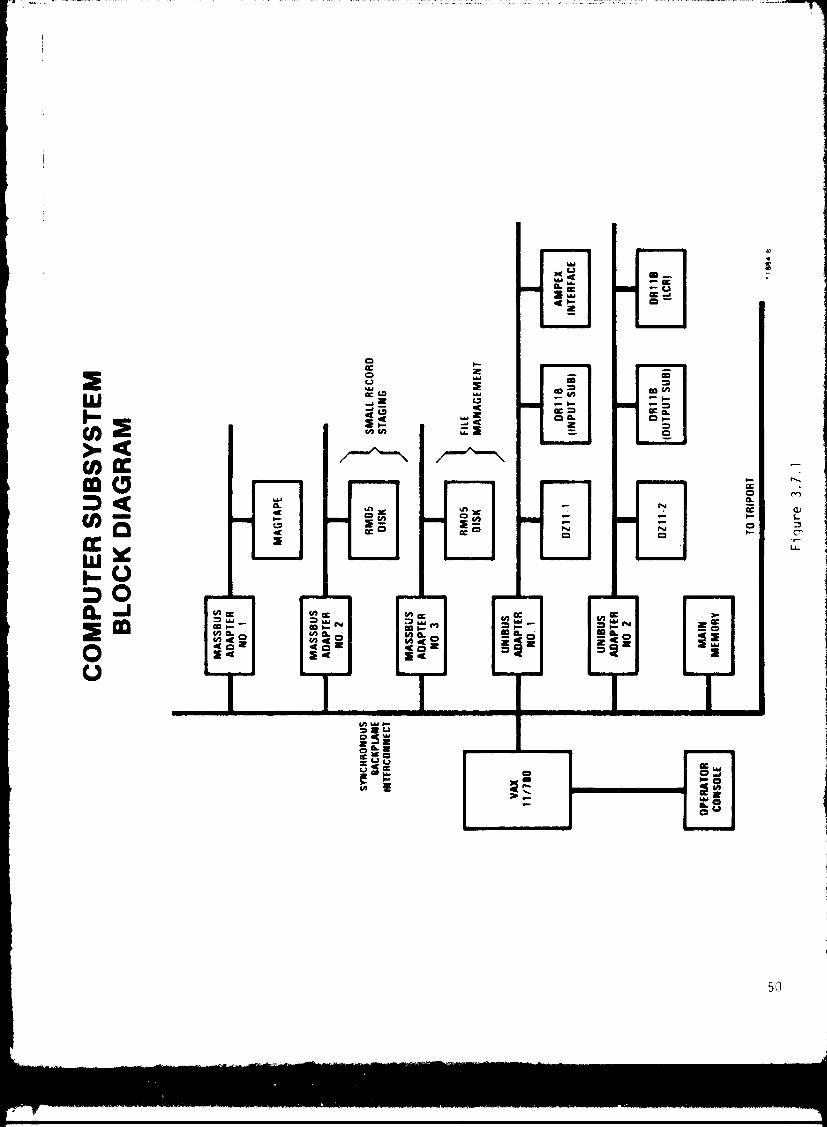
3.7.1 Computer Subsystem Functional Characteristics
The Computer Subsystem functional allocation is specified in
Figure 3.1.4.5.1. Generic VAX-11/780 characteristics are specified in
the vendor documentation. The AMM-13 utilization of these characteristics
is described in the following paragraphs and the Computer Subsystem block
diagram depicted in Figure 3.7.1.
3.7.1.1 Triport Information Exchange
Information shall consist of system status, incoming records
for archiving. ou t going records retrieved from the archive, and file
mario,iornent data.
3.-.1.: Indices File
The indices shall be stored on a RM05 magnetic disk. Each
index contains 128 bits as shown.
S MI I SSC TIME PACKET LOCATION
D
8 8 16 32 64
DATA
BITS
49
2W1-U)
U)m
WH
a
OV
QIm0Q
VOJm
Mi
LL
50
Up to 12.5 million indices shall be stored on the RM05.
3.7.1.3 Software Memory
Up to 80 Mbytes of RM05 disk memory and 500K bytes of core
shall be allocated to house the resident software. Programs shall be
loaded from the magnetic tape unit and/or the operator console.
3.7.1.4 Subsystem Command/Control/Status Links
Comiiunications links to/from the Input, Recorder, Verify,
Storage and Retrieval, Output, and Low Cost Reader Subsystems shall be
provided via a DCC DI-11 standard port employin g RS 2320 links at 19.2K
bits/sec.
3.1.1.5 Data Transfer Links
Small records and large record headers shall be transferred
from the Input Subsystem to the Computer Subsystem via a standard DR-11B
Direct Memory Access (DMA) port. Small records to be recorded in the
archive shall be transferred from the RM05 to the Input Subsystem ( AMPEX
iii ,,k) via the interface to the AMPEX low speed 1/0 port. Data requests
serviced by the Low Cost Reader Subsystem shall be transferred to the
Computer Subsystem via a standard DR-11B DMA port. These requested data
shall he output from the Computer Subsystem either to the Triport via the
`vnchronous Backplane Interconnect (SBI) or the Output Subsystem via a
standard DR-11B DMA port. Requests for data staged on the AMPEX disk
shall be transferred from the AMPEX via the low speed 1/0 port to the
(:0111t)uter Suhsystem.
i
51
3.7.1.6 Data I/O Buffering
In addition to the buffering provided by the standard
interface ports, 500K bytes of core memory shall be reserved for data
1/0 buffering of records and requested data.
3.7.1.7 0 erator Interaction
The system operator shall interact with the system via the
operator console. The need for operator interaction to support operation
of the AMM-13 system shall be minimized.
3.7.1.8 Small Record Staging
Small records ingested via the input Subsystem and/or the
Triport shall be staqed on a dedicated RM05 three hundred Mbyte magnetic
disk in the Computer Subsystem. When a fiche worth of small records
have been staged on the RM05, these records shall be transferred to the
AMfFX disk for recording on fiche. This process shall not interfere with
other AMM functions (See priorities in Paragraph 3.7.2.9).
3.7.1.9 Internal Status
Status of the Computer Subsystem and its peripherals shall
be obtained via the standard DEC operating system.
3.7.1.10 Equipment List
the Computer Subsystem shall consist of the following DEC
equipments:
5

Model Description Quantity
SVAXDBA-CA Basic system includes: 1
11/780 CPU 1MB ECC/MOS
Memory RM05 Disk/Controller
Magnetic Tape Unit
Operating System
Unibus Cabinet
Expansion Box
Two SU Backpl,rne
DZ-11 EIA Interface
Operator Console
RM05 Magnetic Disk/Controller 1
DR-11B DMA Interface 3
D7-11 EIA Interface 1
UNISUS Adapter 2
MASSBUS Adapter 3
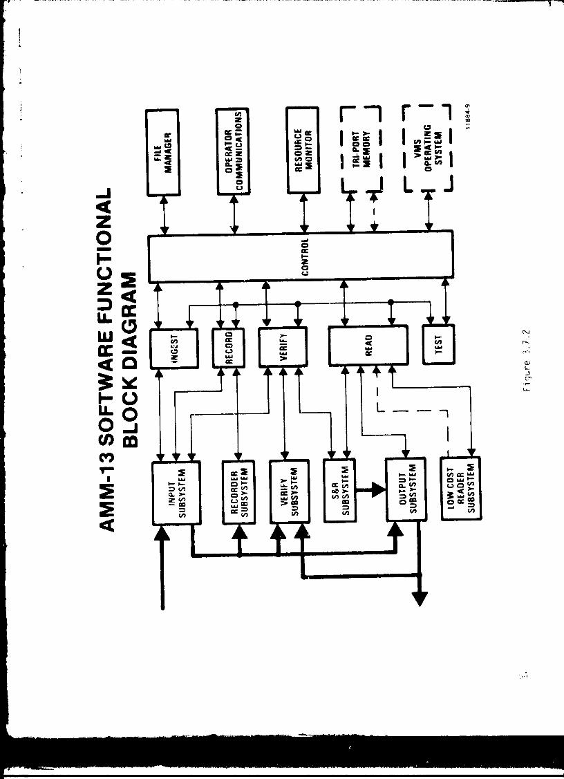
3.'.2 Software Subsystem Functional Characteristics
The Software Subsystem functional allocation is specified in
Figure 3.1.4.5.2. Detailed characteristics shall be described in the
DEC vendor documents and the Software Subsystem Specification. The
Software Subs y stem Block Diagram is depicted in Figure 3.7.2.
3.1.2.1 Supervise and Monitor Resources
the Software Subsystem shall provide all supervisory functions
and connuands within the AMM-13 to prompt the various on-line subsystems
into readiness and convey necessary instructions for perforrninq system
level functions. The Software Subsystem shall also provide a resource
53
N r-I r-^ mwW cc
°.Wit
^0 I I C7I ti^^dc
o0N=I W z N O
~ a I I iO yJ ° LQ ,ZO OccCaZQ TU.0
WQ
Od:1
^-N^w O
ccW
Q O — acv
LL L -- 10 JU mM
W W W y"' O W ►"'ONG W
^ NV2
O>>N
6u V2
NNca N
a yO N ; W N
N Q y N y N N
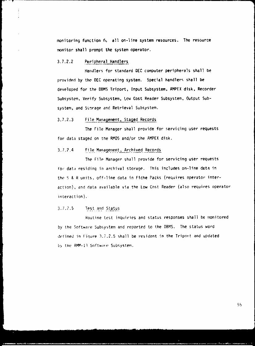
monitoring function fL all on-line system resources. The resource
monitor shall prompt the system operator.
3.7.2.2 Peripheral Handlers
Handlers for standard DEC computer peripherals shall be
provided by the DEC operating system. Special handlers shall be
developed for the DBMS Triport, Input Subsystem, AMPEX disk, Recorder
Subsystem, Verify Subsystem, Low Cost Reader Subsystem, Output Sub-
system, and Storage and Retrieval Subsystem.
3.7.2.3 File Management, Staged Records
The File Manager shall provide for servicing user requests
for data staged on the RM05 and/or the AMPEX disk.
3.7.2.4 File Management, Archived Records
The File Manager shall provide for servicing user requests
for data residing in archival storage. This includes on-line data in
the S & R units, off-line data in Fiche Packs (requires operator inter-
action), and data available via the Low Cost Reader (also requires operator
interaction).
3.7.2.5 Test and Status
Routine test inquiries and status responses shall be monitored
by the Software Subsystem and reported to the DBMS. The status word
defined in figure 3.7.2.5 shall be resident in the Triport and updated
b .y the AMM-11 S0ftWdtV Subsystem.
55
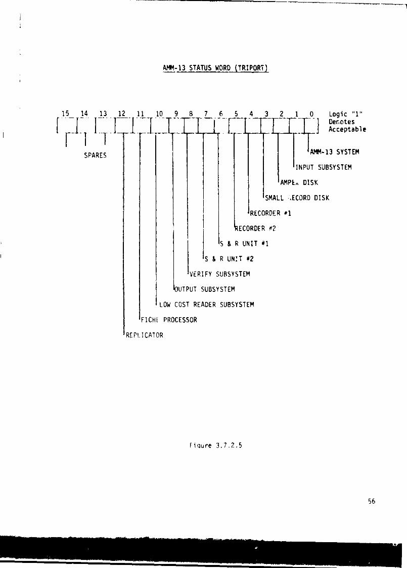
AMM-13 STATUS WORD (TRIPORT)
15 14 13 1
^ 1 1SPARES
2 11_ 10 9 S 1 6 5 4 3 2_ 1 0 Logic "1"( Denotesy _ _ ] Acceptable
AMM-13 SYSTEM
INPUT SUBSYSTEM
AMPS„ DISK
SMALL ,ECORD DISK
IRECORDER 01
ECORDER h2
S & R UNIT M1
S&R UNIT #2
VERIFY SUBSYSTEM
UTPUT SUBSYSTEM
LOW COST READER SUBSYSTEM
FICHE PROCESSOR
REPLICATOR
Fiqure 3.7.2.5
56

3.7.2.6 Data Request Interpreter
The Software Subsystem shall interpret data requests placed
in the I.^vel 3 Queue by the DBMS. Interpretation shall include: deter-
mination of whether data is resident in the AMM, optimization of retrieval,
determination of request start byte within a packet, and determination of
the number of bytes to be output.
3.7.2.7 Verification Assessment
Based upon the biy-by-bit comparison performed by the Verify
Subsystem, the Software Subsystem shall assess the comparison results to
determine what (if any) re-recording is necessary.
3.7.2.8 Data Routing
The Software Subsystem shall control the destination of all
data within the Computer Subsystem.
3.7.2.9 I/O Priories
Top priority sha'11 be given to those functions which support
the high speed data ingest process. Those functions which support the
high speed data out put process shall be given equal priority unless the
AMM is operating in a degradad mode (such as having one S & R unit inoperative).
Data I/O via the Triport, servicing of requests for d i sk staged records,
and small record recording, shall be prioritized in the order as listed.
3.7.2.10 AMPEX Formattin_9
The Software Subsystem shall provide format instructions to
the AMPEX disk. The format shall support AMPEX ingest of b X 109 bits
witnin two minutes. In conjunction with the forward file management of
records during the recording process, records shall be transferred to the
Recorder Subsystem in such a manner that packets are not split between two
or more fiche.
57

3.7.3 Input Subsystem Functional Characteristics
The Input Subsystem functional allocation is specified in
Figure 3.1.4.5.3 and the functional block diagram is shown in Figure 3.7.3.
3.7.3.1 DBMS, Port Data Ingest Control
The Input Subsystem shall control the ingest of data via the
high speed port. This control function ,nall be provided by the interface
defined in the AMM/DBMS Interface Control Document.
3.7.3.2 Nigh Speed Data Ingest Clock
This clock shall be provided by the AMM Input Subsystem and
shall run at 1.6 MHz.
3.7.3.3 Small vs. Large Record Determination
The Input Subsystem shall provide the small vs. large record
determination by interpretation of the PL and/or PLI fields in the packet
headers. Initially, this boundary shall be set at 16,384 bits (and below)
to signify small records.
3.7.3.4 Small Record Extraction
Small records shall be extracted from the ingest data stream
and routed to the Computer Subsystem for staging. The ingest rate of 51.2
Mb/s and the computer DMA average transfer rate of 1.0 Mb/s shall require
buffering of small records in the Input Subsystem.
3.7.3.5 Lame _Record Headers
The first 128 bits of each large record packet header shall
be copied by the Input Subsystem from the ingest data stream and routed
to the Computer Subsystem for forward file management of the recording
process. Large record headers shall be rate buffered in the Input Subsystem
in a buffer which is independent from the small record rate buffer. Groups
58

L-1 q
Jaz0HUzM
2w
U)
az
WaLAJ Wa Lid W W ^ i
a go so u 0 CID cc 0W > > > W =t1 N1 UCCA cc V) ON ?N
MnMi7
l.^
craCLN
coO
2atrt^a0
U0co

of large record headers shall be transferred to the Computer Subsystem
via the same DR-11B port used for small record transfer on a port time
shared basis.
3.7.3.6 AMPEX High Speed Data Ingest
The Input Subsystem shall provide the necessary data handling/
buffering functions to accomodate the AMPEX disk ingest without interrupting
the data ingest stream via the high speed DBMS port. From input to output
the AMPEX disk shall maintain a bit error rate less than 10-10
3.7.3.7 AMPEX High Speed Data Output to Recorder . Sub^jstem
The Input Subsystem shall provide the necessary data handling/
buffering functions to accomodate the R-corder Subsystem.
3.7.3.8 AMPEX High Speed Data Output to Verify Subsystem
The Input Subsystem shall provide the necessary data handling/
buffering functions to insure synchronization of the two data streams
received by the Verify Subsystem.
3.7.3.9 AMPEX High Speed Data Output to Output Subsystem
The Input Subsystem shall provide the necessary data handling/
buffering functions to accomodate the Output Subsy,to:,..
3.7.3.10 Internal Status
Status of the Input Subsystem shall be conveyed to the Computer/
Software Subsystems via a 19.2Kb/s RS 232C link with the DZ11 port.
3.7.4 Recorder Subsystem Functional_ Characteristics
The Recorder Subsystem functional allocation is specified in
Figure 3.1.4.5.4 and the functional block diagram is shown in Figure 3.7.4.
60

I2a
WNaU Ym VCO) J^ mW JOQcc Z00W ~CCVZ
U.
an s^W W W WIL r r4 NN NO CA O CACi N C7 N
W W LCW
C ^! atIC
oe .4 O~ v= v= ZO O
C.)
I-xx= H dNmCAN
L7
61
3.7.4.1 High Seed Data Ingest Control
The Recorder Subsystem shall control the ingest of data from
the Input Subsystem. This control function shall be provided via the
interface defined in Paragraph 3.1.5.2.3. The Input Subsystem shall provide
data to the Recorder Subsystem when requested by the Recorder Subsystem.
(See Paragraph 3.7.3.7). The Recorder Subsystem shall conta i n two recorders
operating in a ping-pong fashion to support the Input Subsystem ingest duty
cycle requirements. The encoding function which supports error detection
and correction, shall be shared by the two recorders.
3.7.4.2 High Speed Data Ingest Clock_
This clock shall be provided by the Recorder Subsystem and
shall be of such a rate that 109 bits of data shall be transferred within
20 seconds.
3.7.4.3 Record Oata on Photographic_ Film
The Recorder Subsystem shall provide all functions necessary
to transform the ingested data stream from the Input Subsystem AMPEX disk
into optically exposed spots on 148mm square, 7 mil thick fiche or KODAK
SO 343 photographic film such that the input data has a bit error rate of
less than or equal to 10 -9 when compared to the
di ,,k. the optical spot recording process shall
usor bit density of at least 30Mbits per square
remove a previously exposed fiche, insert it in
extract and position an unexposed fiche, and be
unexposed fiche within 15 seconds.
data stored on the AMPEX
provide for an equivalent
inch. The recordEr shall
to the exposed fiche magazine,
reedy to record on the
62

3.7.4.4 Fiche Loadinq/Unloading
Each recorder in the Recorder Subsystem shall provide a port
for operator insertion of a magazine containing 10 unexposed fiche and
shall provide a seperate port for operator insertion of an empty magazine
into which the recorder shall place exposed fiche. The exposed fiche
magazine shall be capable of accepting 10 exposed fiche. All magazines
and port interfaces shall be identical except for external markings. Each
recorder shall provide all internal functions required to extract unexposed
fiche from the unexposed fiche magazine and insert exposed fiche into the
exposed fiche magazine.
3.7.4.5 Internal Status
Status of the Recorder Subsystem and of each recorder in the
Recorder Subsystem, shall be conveyed to the Computer/Software Subsystem
via a 19.2Kb/s RS 232C link with the DZ11 port.
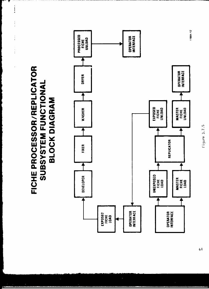
3.1.5 Fiche Processor/Replicator_Functional Characteristics
The Fiche Processor/Replicator Subsystem functional allocation
is specified in Figure 3.1.4.5.5 and the functional block diagram is shown
in Figure 3.7.5.
3.7.5.1 Fiche Loading/Uiloading
The processor shall provide for operator insertion of exposed
fiche and shall provide for operator extraction of processed fiche. The
replicator shall provide for operator insertion and extraction of fiche.
3.7.5.2 Fiche Processing
This shall be an automatic function which includes: developing
tho film, fixing, wa ,> hinq the film, and dryinn the fiche.
63
ccO
avJaW
ONNWVOocaW
VW
Qz0VzmW
WI—
U)m
N
Ln
M
CT
2Qcc0Q
YVOJco
F
64
1- 2W W=Nayam "H
65

3.7.5.3 Replication
This shall be an off-line operator assisted function to
perform replication of data onto another fiche by contact replication.
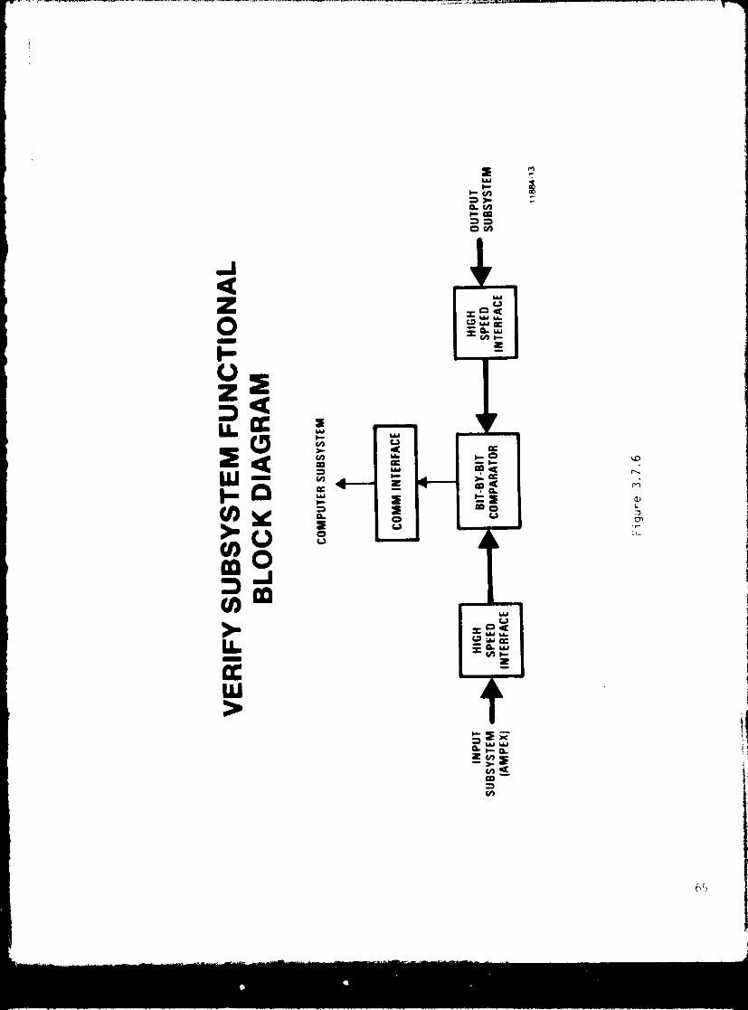
3.7.6 Verify Subsystem Functional_ Characteristics
The Verify Subsystem functional allocation is specified in
Figure 3.1.4.5.6 and the functional block diagram is shown in Figure 3.7.6.
3.7.6.1 High Speed Data_Ingest Control
This control function shall be provided by the Input Subsystem
to insure synchronism of the input streams from both the Output Subsystem and
the Input. Subsystem.
3.7.6.2 Bit-by-Bit Comparison
This function shall be a binary decision process which deter-
mines whether or not the bits represent the sanrc logical value. Data contained
on one fiche (10 9 bits) shall be compared in less than 20 seconds.
3.7.6.3 Comparison Results
This shall be a data transfer function. The Verify Subsystem
conveys the number of errors detected to the Computer/Software Subsystem via
the D1-11 RS 232C interface.
Storage and_ Retrieval Subsystem Functional Characteristics
The Sto r.ige and Retrieval Subsystem functional allocation is
specified in Figure 3.1.4.5.7 and the functional block diagram is shown in
F i guve 3.7.1.
1 I i( lie I c aciin^3/Unloading
Lach of the two on-line storage and retireval units shall provide
a port for operator insertion of a magazine containing processed master and/or
replicated fiche. Insertion of fiche into the fiche pack shall be an operator
66

QH
•^yo
y WIL>IL vo
O H13 W
O H
tt Wyr
cc Wh^ V
S n^O WU=
cp WL=ti
S W^^W
= d' W S d= WW CA r-O= of r
O=
oC cc
aW acJ W
JJ
=Oa ZQ
W Z W° O OQ ¢
OU
OU
< QNW
W W OHNWU
OSU0
Wd ^
°O Ic OC ; 4
WNI,49 °WW
S
cc
J
W
Q
LLI jW
=OH
W
=W° =Q W°
Q Z. Od aOz
0
W W
H y ^ HW (, yC0
y Jy^0
0 ZQ^cc U.O W
QW/w S r Q Qv, W O J O W
N tWW
W
Z i a `p
C7 f„ WS t^ = OC S
N.^ O Z "'^ N =
nMN17CT
11.
h:^
assisted function. The same port shall also be utlized for operator
assisted extraction of fiche from the fiche pack into a fiche magazine
and operator extraction of the magazine.
3.7.7.2 Fiche Storage
Unexposed fiche storage facilities shall not be provided by
AMM-13. Processed master and/or replicated fiche shall be stored in on-
line fiche packs residing in the S & R units or off-line fiche packs
residing in cabinets. Each fiche pack shall be capable of storing at least
1000 fiche in such a manner that data resident on the fiche will satisfy
the system bit error rate requirements for at least 10 years of archival
storage.
3.7.7.3 Fiche Pack Loadinn
Off-line fiche packs shall be capable of operator assisted
loading into on-line S & R units. The process of removing an on-line fiche
pack and replacing it with an off-line fiche pack shall be such that an
operator can perform the process within three minutes.
3.7.7.4 Retrieval and Readin
Each of the two S & R units in the Storage and Retrieval
Subsystem shall provide all functions necessary to retrieve fiche containin-
requested data from its fiche pack, position the fiche in the reader, read
the data, and replace the fiche in its previous loaction in the I iche pack.
3.7.7.5 HighS e^ ed Oa_ta Out Lit Control
The Storage and Retrieval Subsystem and the Output Subsystem
control the output of data from the individual S & R units. This control
function shall be accomplished via the 'interface defined in Paragraph 3.1.5.2.7.
68

When the DBMS bus is accepting data and the Output Subsystem is not
performing interleaving of data, the S & R unit shall control the
output of data. When the buffers in the Output Subsystem are saturated
with data, the Output Subsystem shall interrupt the S & R unit data output.
The S & R unit shall retain the fiche in the read station without reading
data for output. Once the backlog in the Output Subsystem buffers has
been sufficiently cleared, the S & R unit shall proceed with reading and
outputting of data. The maximum delay in data output resulting from this
condition shall be equal to the once-around time for the particular track
being read. (See Paragraph 3.7.7.6).
3.7.1.6 High Seed Data Output
Each of the two S & R units shall have autonomous paths for
transferring data to the Output Subsystem. Data output shall be initiated
by the Software Subsystem by notifying the S & R unit of: the fiche location
in the fiche pack, the track on which reading is to begin, the sector which
contains the start of data to be read, the byte count from the start of
sector to the start of data to be read, and the number of bytes to be read.
The S & R unit shall automatically retrieve the fiche, position the fiche,
locate the start of sector, and begin scanning the spots. If one of the two
EDAC interleaver buffers is empty, the encoded scanned data in the entire
sector shall be loaded into the interleaver buffer. Upon completion of loading,
the EDAC processor starts decoding and outputting data to the Output Subsystem.
(Note: if the Output Subsystem buffers are saturated (see Paragraph 3.7.7.5),
the encoded data shall remain in the EDAC buffer and output shall not begin).
If the requested data overlaps into the next sector, the entire sector shall
be loaded into the other interleaver buffer (assuming that the buffer is empty).
This ping-pong process shall continue until all requested data has been loaded
into the interleaver buffers and/or transfer-2d to the Output Subsystem.
69

Each S b R Unit shall transfer only the number of bytes requested to the
Output Subsystem.
3.7.7.7 Internal Status
Status of the Storage and Retrieval Subsystem and of each
S 6 R Unit shall be conveyed to the Computer/Software Subsystem via a
19.2Kb/s RS 232C link with the OZ-11 port.
3.7.8 Out ut Subsystem Functional Characteristics
The Output Subsystem functional allocation is specified in
Figure 3.1.4.5.8 and the functional block diagram is shown in Figure 3.7.8.
3.7.8.1 DBMS Port Data Output Clock
The Output Subsystem shall control the output of data to the
high speed port. This control function shall be provided by the interface
defined in the AMM/DBMS Interface Control Document.
3.7.8.2 DBMS Port Data Output Clock
This clock shall be provided by the AMM Output Subsystem and
shall run at 1.6 MH7.
3.7.8.3 Data_ Transfer to DBMS Port
Data transferred via this port shall be in response to data
requests resident in the Triport Data Request Queue. The Output Subsystem
shall provide a set of buffers for staging the data prior to output to the
DBMS port. This buffering shall be structured to provide storage by
Destination Address in support of the frame-by-frame interleaving requirement.
70

ZN t N Z Z
y
QO OW Y Z O
14W
O 4949W
WW m cc —
~cc
^
1_
ZZ— ►-
zZCL
Q OmHO
OW
LA, W> CC OW4c V
CLNO
H Wt W W Scc
S
LU Q ^W W ^ W
^N
^VO W W
m
a WVdo
W= 0 4
O ^ W= d = W
OZ N O
r Q YaO W ^,
'" ..= Woc r—
H CL
N Nm p m
V ym
O y
hr,vi7
;1

3.7.8.4 Data Exchange with Computer Subsystem
Requested data to be serviced through the DBMS port which
has been retrieved from the RM05 small record disk or the Low Cost Reader
Subsystem shall be routed via the Computer Subsystem to the Output Sub-
system. Ingest of the data by the Output Subsystem shall be via the DR-11B
DMA transfer port. Ingested records shall be routed from the port into the
Output Subsystem staging buffers. Requested data to be serviced through the
Triport which has been retrieved from the AMPEX disk or the Storage and
Retrieval Subsystem shall be buffered within the Output Subsystem to accomo-
date transfer rate differences. Output of the data to the Computer Subsystem
shall occur on a time shared basis using the DR-11B DMA transfer port.
3.7.8.5 Hitch Speed Data Output to Verif, Subsystem
This data transfer shall be such that the S & R Unit reading
function is not interrupted. The Output Subsystem shall perform a pipeline
function from the S & R Unit to the Verify Subsystem.
3.7.8.6 Tnternal Status
Status of the Output Subsystem shall be conveyed to the
Computer/Software Subsystem via a 19.2Kb/s RS 232C link with the DZ-11 port.
3.7.9 Low Cost Reader Subsystem Functional Characteristics
The low Cost Reader Subsystem functional allocation is specified
in Figurt 3.1.4.5.9 and the functional block diagram is shown in Figure 3.7.9.
3.7.9.1 Data_ Output Colt, _)1
Control of the data flow from the Low Cost Reader Subsystem to
the Computer S-ibsystem shall be a shared function between the two subsystems
72
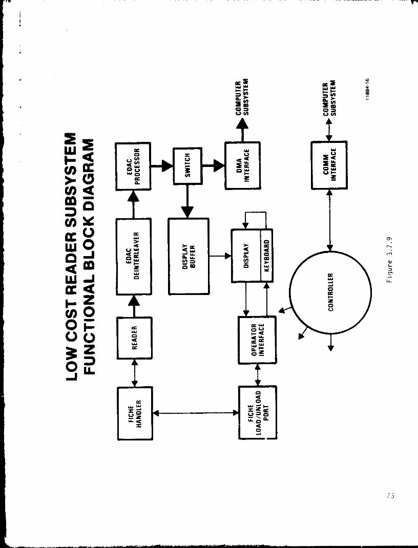
0 H hdO ^V N
cc WW ^f- N
^' mO TCi N
Mi7
2WQ ^y u x
CCQ W
ciud
I.- X oCO
Ocr.CL.
H /-Z
Q
(a^d/^Ii U ocWWOJ W g^ sQQW^o °CW 196 ^y
O O
aNO
m
WWO
Y
ZU) OO Q WV
ujO O 4tQ
ZW
WWO ZOPW nOU.
Od
I O
W W W - f'
t^ 0 c> > O
W Q IL O d
T. dO
73

with the Computer Subsystem exercising ultimate responsibility by controlling
its input port.
3.7.9.2 Data Transfer
Data shall consist of small records in the Low Cost Reader
Subsystem. ;iie transfer may be initiated either by a normal user request,
^ the Low Cost Reader operator wishing to stage small records on the
disk for later recall by a user at disk access rates. Data transfer
shall be a DMA transfer via a dedicated DR-11B port.
3.7.9.3 Fiche Loading/Unloading
The fiche loading /unloading function shall be an operator
assisted process. For loading, the operator shall insert a replicated fiche.
For unloading, the operator shall remove the replicated fiche. There shall
be one magazine port.
3.7.9.4 Reading
The Low Cost Reader Subsystem shall be capabie of reading
replicated fiche. The reading function shall include all processes necessary
to: interpret record location, select/extract the fiche from the magazine,
position the fiche in the read station, optically scan the spots on the
fiche, transform those spots into a coded bit stream, perform error detection
and correction, route the requested data to the Display or the output port,
and replace the fiche in the magazine.
3.7.9.5 Data Buffering for Local Display
Tne Low Cost Reader display buffer shall provide rate buffering
to accomodate the display.
74
i
3.7.9.6 Alphanumeric Display
The display shall be a standard alphanumeric CRT terminal
capable of displaying at least 40 lines with 80 characters per line.
3.7.9.7 Operator Interface, Keyboard
This interface shall provide the operator with the capability
to specify records to be read from the fiche in the Low Cost Reader Sub-
system. Specification of the record shall be accomplished by entering
record location data via the keyboard in the same location format as that
maintained by the AMM-13 File Manager. The operator shall obtain the record
location either from a hard copy directory or by inquiry to the AMM-13 File
Manager. This interface shall also provide for operator communications with
the Software Subsystem via a DZ-11 RS 232C communications link. The keyboard
shall contain at least the standard 64 ASCII character keys. The keyboard
shall also provide for character display on the local alphanumeric CRT terminal.
3.7.9.8 Internal Status
Status of the Low Cost Reader Subsystem shall be conveyed to
the Computer/Software Subsystem via a 19.6Kb/s RS 232C link with the DZ-11
port.
4.0 QUALITY ASSURANCE PROVISIONS
4,1 General
Tests and evaluations shall be conducted to verify that the
design and performance of the AMM-13 meets or exceeds the requirements
specified herein. These objectives shall be implemented in accordance with
the AMM-13 Engineering Test Plan (ETP).
75
6— —
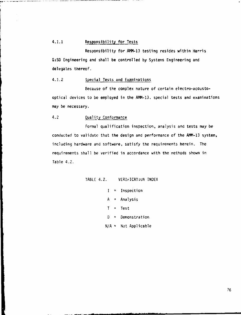
4.1.1 Responsibility for Tests
Responsibility for AMM-13 testing resides within Harris
GiSD Engineering and shall be controlled by Systems Engineering and
delegates thereof.
4.1.2 Special Tests and Examinations
Because of the complex nature of certain electro-acousto-
optical devices to be employed in the AMM-13, special tests and examinations
may be necessary.
4.2 guali
Formal
conducted to validate
including hardware an
requirements shall be
Table 4.2.
y Conformance
qualification inspection, analysis and tests may be
that the design and performance of the AMM-13 system,
J software, satisfy the requirements herein. The
verified in accordance with the methods shown in
TABLE 4.2. VERIrICAT1UN INDEX
I = Inspection
A = Analysis
T = Test
D = Demonstration
N/A = Not Applicable
76
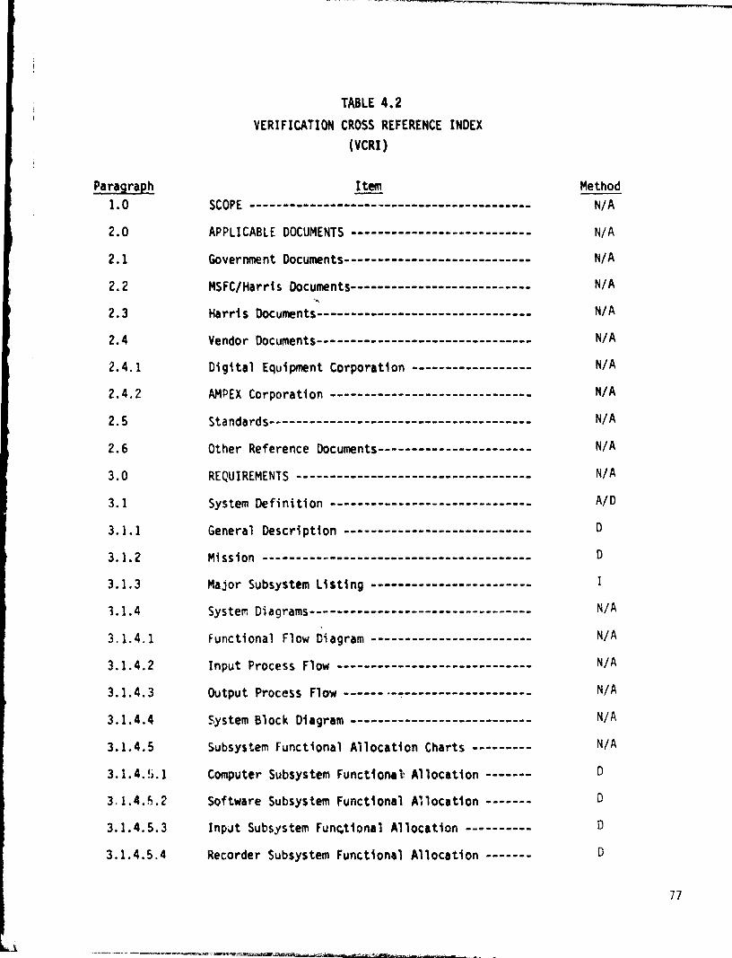
TABLE 4.2
VERIFICATION CROSS REFERENCE INDEX
(VCRI)
Paragraph Item Method
1.0 SCOPE ------------------------------------------ N/A
2.0 APPLICABLE DOCUMENTS --------------------------- N/A
2.1 Government Documents---------------------------- N/A
2.2 MSFC/Harris Documents--------------------------- N/A
2.3 Harris Documents-------------------------------- N/A
2.4 Vendor Documents-------------------------------- N/A
2.4.1 Digital Equipment Corporation ------------------ N/A
2.4.2 AMPEX Corporation ------------------------------ N/A
2.5 Standards--------------------------------------- N/A
2.6 Other Reference Documents----------------------- N/A
3.0 REQUIREMENTS ----------------------------------- N/A
3.1 System Definition ------------------------------ A/D
3.1.1 General Description ---------------------------- D
3.1.2 Mission ---------------------------------------- D
3.1.3 Major Subsystem listing ------------------------ I
5.1.4 System Diagrams--------------------------------- N/A
3.1.4.1 Functional Flow Diagram ------------------------ N/A
3.1.4.2 Input Process Flow ----------------------------- N/A
3.1.4.3 Output Process Flow ---------------------------- N/A
3.1.4.4 System Block Diagram --------------------------- N/A
3.1.4.5 Subsystem Functional Allocation Charts --------- N/A
3.1.4.5.1 Computer Subsystem Functional Allocation ------- D
3.1.4.5.2 Software Subsystem Functional Allocation ------- D
3.1.4.5.3 Input Subsystem Functional Allocation ---------- D
3.1.4.5.4 Recorder Subsystem Functional Allocation ------- D
77

3.1.4.5.5 Fiche Processor/Replicator Subsystem Functional
Allocation ------------------------------------------ D
3.1.4.5.6 Verify Subsystem Functional Allocation ------------- D
3.1.4.5.7 Storage and Retrieval Subsystem Functional
Allocation ----------------------------------------- D
3.1.4.5.8 Output Subsystem Functional Allocation ------------- D
3.1.4.5.9 Low Cost Reader Subsystem Functional Allocation ---- D
3.1.4.6 Detailed System Block Diagrams --------------------- N/A
3.1.5 Interface Definition ------------------------------- N/A
3.1.5.1 External Interfaces -------------------------------- T/D
3.1.5.2 Internal Interfaces -------------------------------- D
3.1.5.2.1 Computer and Software Subsystem Interfaces --------- D
3.1.5.2.2 Intentionally Blank ----------------------•---------- N/A
3.1.5.2.3 Input Subsystem Interfaces -------------------------- D
3.1.5.2.4 Recorder Subsystem Interfaces ---------------------- D
3.1.5.2.5 Fiche Processor /Replicator Subsystem Interfaces ---- D
3.1.5.2.6 Verify Subsystem Interfaces ------------------------ D
3.1.5.2.7 Storage and Retrieval Subsystem Interfaces --------- D
3.1.5.2.8 Output Subsystem Interfaces ------------------------ D
3.1.5.2.9 Low Cost Reader Subsystem Interfaces --------------- D
3.1.5.3 Facilities Interface ------------------------------- I
3.1.6 Gover-iment Furnished Property List ----------------- I
3.1.7 Operational and Organizational Concepts ------------ N/A
3.1.7.1 Operational Concept ----------------------- -------- D
3.1.7.2 Organizational Concepts ---------------------------- D
3.2 Characteristics ------------------------------------ N/A
3.2.1 Performance Characteristics ------------------------ N/A
3.2.1.1 Data Storage Capacity ------------------------------ N;A
78
J
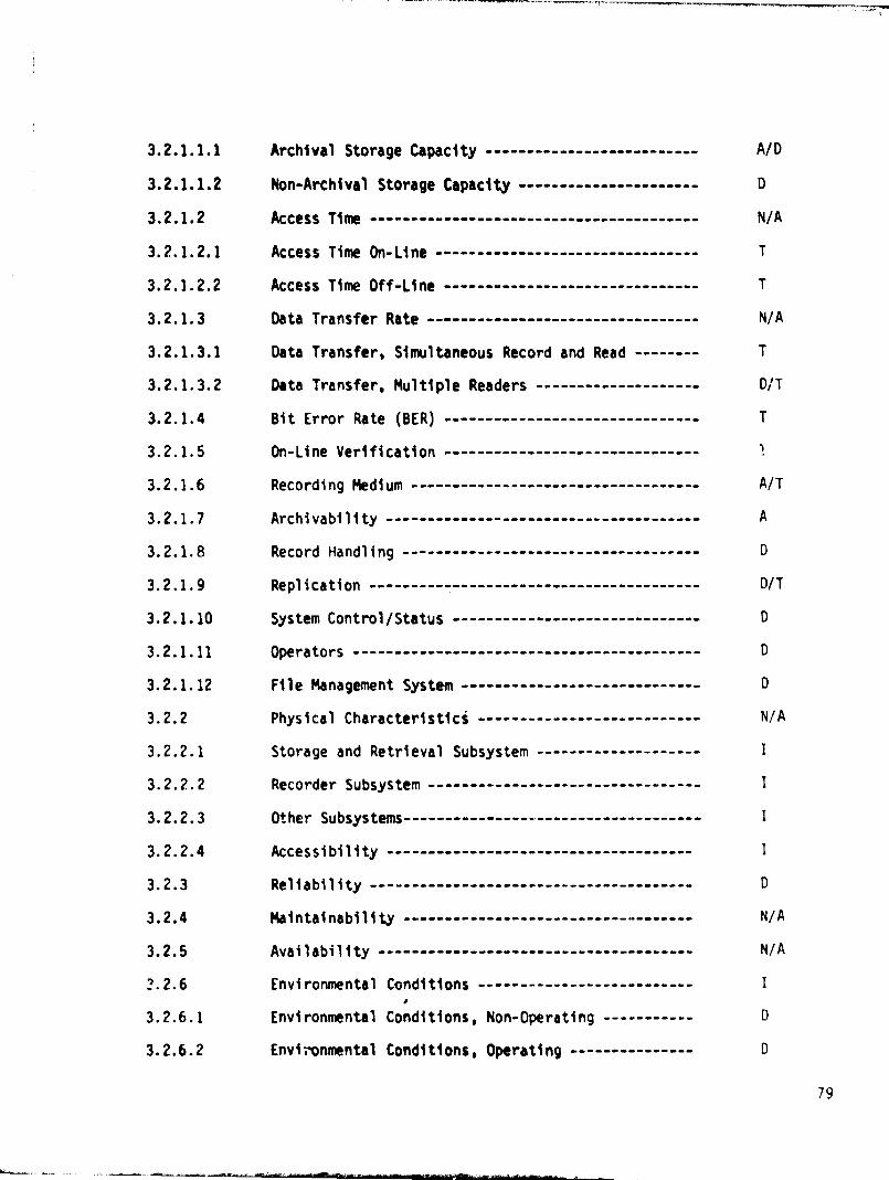
3.2.1.1.1 Archival Storage Capacity -------------------------- A/D
3.2.1.1.2 Non-Archival Storage Capacity ---------- ------------ D
3.2.1.2 Access Time ---------------------------------------- N/A
3.2.1.2.1 Access Time On-Line -------------------------------- T
3.2.1.2.2 Access Time Off -Line ------------------------------- T
3.2.1.3 Data Transfer Rate --------------------------------- N/A
3.2.1.3.1 Data Transfer, Simultaneous Record and Read -------- T
3.2.1.3.2 Data Transfer, Multiple Readers -------------------- D/T
3.2.1.4 Bit Error Rate (BER) ---------------------------- --- T
3.2.1.5 On-Line Verification -------------------------------
3.2.1.6 Recording Medium ----------------------------------- A/T
3.2.1.7 Archivability -------------------------------------- A
3.2.1.8 Record Handling ------------------------------------ D
3.2.1.9 Replication ---------------------------------------- D/T
3.2.1.10 System Control/Status ------------------------------ D
3.2.1.11 Operators ------------------------------------------ D
3.2.1.12 File Management System ----------------------------- D
3.2.2 Physical Characteristics --------------------------- N/A
3.2.2.1 Storage and Retrieval Subsystem -------------------- I
3.2.2.2 Recorder Subsystem --------------------------------- I
3.2.2.3 Other Subsystems------------------------------------ I
3.2.2.4 Accessibility ------------------------------------- I
3.2.3 Reliability --------------------------------------- D
3.2.4 Maintainability ----------------------------------- N/A
3.2.5 Availability -------------------------------------- N/A
2.2.6 Environmental Conditions -------------------------- I
3.2.6.1 Environmental Conditions, Non-Operating ----------- D
3.2.6.2 Envirronmental Conditions, Operating --------------- D
79
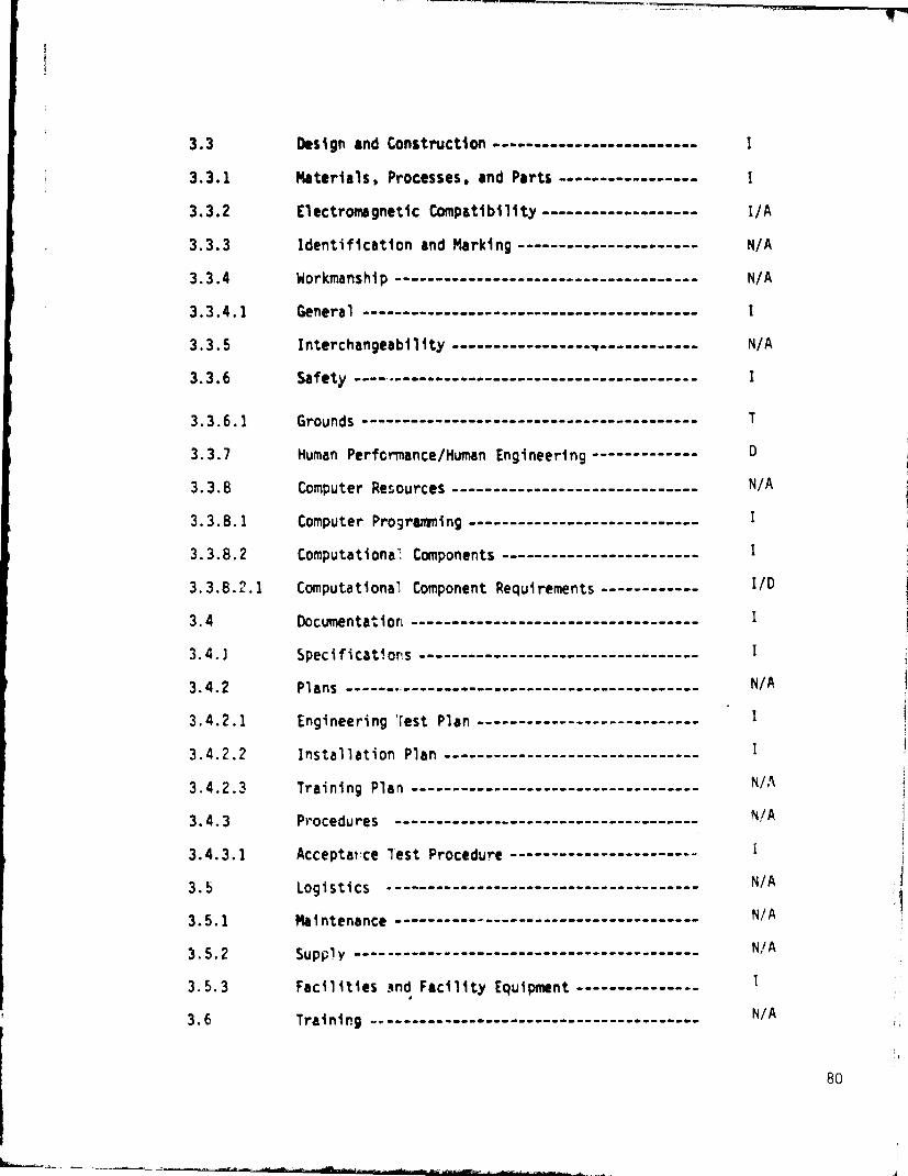
3.3 Design and Construction ------------------------- I
3.3.1 Materials, Processes, and Parts ----------------- I
3.3.2 Electromagnetic Compatibility ------------------- I/A
3.3.3 Identification and Marking ---------------------- N/A
3.3.4 Workmanship ------------------------------------- N/A
3.3.4.1 General ----------------------------------------- I
3.3.5 Interchangeability ----------------- , ------ ------ N/A
3.3.6 Safety ----•------------------------------------- 1
3.3.6.1 Grounds ----------------------------------------- T
3.3.7 Human Performance/Human Engineering ------------- D
3.3.8 Computer Resources ------------------------------ N/A
3.3.8.1 Computer Programming ------- - ------ - --------- ---- I
3.3.8.2 Computationa': Components ------------------------ I
3.3.8.2.1 Computational Component Requirements ------------ I/D
3.4 Documentation ----------------------------------- 1
3.4.3 Specifications -- ---------------------------- ---- I
3.4.2 Plans -------------- - --------- -------------------- N/A
3.4.2.1 Engineering 'Test Plan --------------------------- I
3.4.2.2 Installation Plan ----- ------------------------- - I
3.4.2.3 Training Plan ----------------------------------- N/A
3.4.3 Procedures --------- ---------------------------- N/A
3.4.3.1 Acceptance lest Procedure -------------------•--° I
3.5 Logistics -------------------------------------- N/A
3.5.1 Maintenance ---------------------------- - ---- ---- N/A
3.5.2 Supply ------------------------------------------ NI/A
3.5.3 Facilities and Facility Equipment --------------- I
3.6 Training --------------- •--- --------------- ------ N/A
80
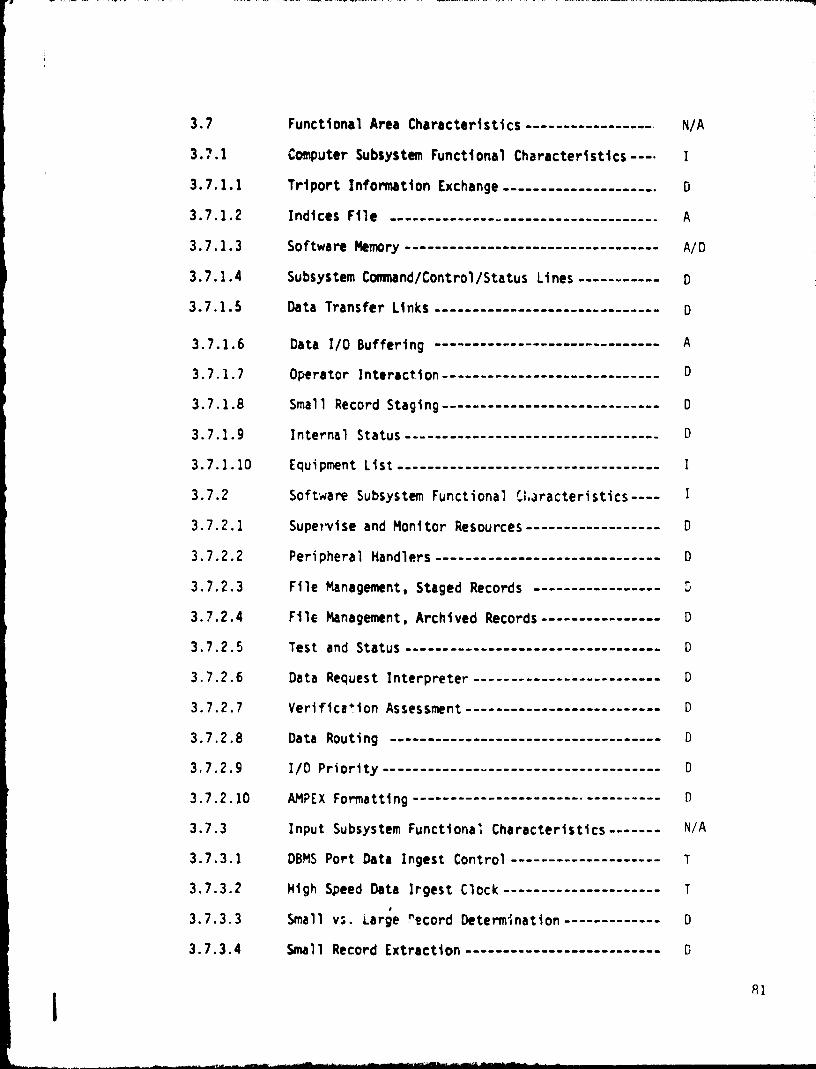
3.7 Functional Area Characteristics ----------------- N/A
3.7.1 Computer Subsystem Functional Characteristics---• I
3.7.1.1 Triport Information Exchange --------------------- D
3.7.1.2 Indices File ------------------------------------ A
3.7.1.3 Software Memory ---------------------------------- A/D
3.7.1.4 Subsystem Command/Control/Status Lines----------- D
3.7.1.5 Data Transfer Links ------------------------------ D
3.7.1.6 Data I/O Buffering ------------------------------ A
3.7.1.7 Operator Interaction----------------------------- D
3.7.1.8 Small Record Staging----------------------------- D
3.7.1.9 Internal Status---------------------------------- D
3.7.1.10 Equipment List----------------------------------- I
3.7.2 Soft-ware Subsystem Functional Cka racteristics---- 1
3.7.2.1 Supervise and Monitor Resources------------------ D
3.7.2.2 Peripheral Handlers ----- ------------------------- D
3.7.2.3 File Management. Staged Records ----------------- D
3.7.2.4 File Management, Archived Records---------------- D
3.7.2.5 Test and Status ---------------------------------- D
3.7.2.6 Data Request Interpreter------------------------- D
3.7.2.7 Verifice'ion Assessment------------------- ------ D
3.7.2.8 Data Routing ------------------------------------ D
3.7.2.9 I/O Priority ------------------------------------- D
3.7.2.10 AMPEX Formatting -------------------------------- D
3.7.3 Input Subsystem Functional Characteristics------- N/A
3.7.3.1 DBMS Port Data Ingest Control-------------------- T
3.7.3.2 High Speed Data lrgest Clock--------------------- T
3.7.3.3 Small vs. Large record Determination ------------- D
3.7.3.4 Small Record Extraction -------------------------- D
81

3.7.3.5 Large Record Headers ------------------------------ D
3.7.3.6 AMPEX High Speed Data Ingest ---------------------- T
3.7.3.7 AMPEX High Speed Data Output to Recorder
Subsystem ----------------------------------------- D
3,7.3 8 AMPEX High Speed Data Output to Verify
Subsystem----------------------------------------- D
3.7.3.9 AMEX High Speed Data Output to Output Subsystem--- D
3.7.3.10 Internal Status ------------------------------------ D
3.7.4 Recorder Subsystem Functional Characte, —tics ----- N/A
3.7.4.1 High Speed Data Ingest Control -------------------- D
3.7.4.2 High Speed Data Ingest Clock ---------------------- T
3.7.4.3 Record Data On Photographic Film ------------------ T/A
3.7.4.4 Fiche loading/Unloading --------------------------- D
3.7.4.5 Internal Status ----------------------------------- D
3.7.5 Fiche Processor/Replicator Functional
Characteristics ----------------------------------- N/A
3.7.5.1 Fiche Loading/Unloading --------------------------- D
3.7.5.2 Fiche Processing ---------------------------------- D
3.7.5.3 Replication --------------------------------------- D
3.7.6 Verify Subsystem Functional Characteristics ------- N/A
3.7.6.1 High Speed Data Ingest Control -------------------- D
3.7.6.2 Bit-by-Bit Comparison ----------------------------- T
3.7.6.3 Comparison Results -------- ----------------------- D
3.7.7 Storaq: and Retrieval Subsystem Functional
Characteristics ------------------------------------- N/A
3.7.7.1 Fiche Loading/Unloading --------------------------- D
3.7.7.2 Fiche S^orage ------------------------------------- 1/T
3.7.1.3 Fiche Pack Loading -------------------------------- D
82

3.7.7.4 Retrieval and Reading -------------------------- D
3.7.7.5 High Speed Data Output Control ----------------- D
3.7.7.6 High Speed Data Output ------------------------- D
3.7.7.7 Internal Status -------------------------------- D
3.7.8 Output Subsystem Functional Characteristics ---- N/A
3.7.8.1 DBMS Port Data Output Control ------------------ D
3.7.8.2 DBMS Port Data Output Clock -------------------- T
3.7.8.3 Data Transfer to DBMS Port --------------------- D
3.7.8.4 Data Exchange with Computer Subsystem ---------- D
3.7.8.5 High Speed Data Output to Verify Subsystem ----- D
3.7.8.6 Internal Status -------------------------------- D
3.7.9 Low Cost Reader Subsystem Functional
Characteristics -------------------------------- N/A
3.7.9.1 Data Output Control ---------------------------- D
3.7.9.2 Data Transfer ---------------------------------- D/T
3.7.9.3 Fiche Loading/Unloading ------------------------ D
3.7.9.4 Reading ---------------------------------------- T
3.7.9.5 Data Buffering for Local Display ---------------- D
3.7.9.6 Alphanumeric Display --------------------------- D
3.7.9.7 Operator Interface. Keyboard ------------------- D
3.7.9.8 Internal Status -------------------------------- D
4.0 QUALITY ASSURANCE PROVISIONS ------------------- N/A
4.1 General ---------------------------------------- I/A
4.1.1 Responsibility for Tests------------------------ I
4.1.2 Special Tests and Examinations ----------------- I
4.2 Quality Conformance ---------------------------- I
83

5.0 PREPARATION FOR DELIVERY ------------------------ I
6 .0 NOTES -------------------------------------------• N/A
6.1 Glossary of Terms -------------------------------• N/A
ATTACHMENT A Detailed System Block Diagrams N/A
84

5.0 PREPARATION FOR DELIVERY
Harris shall package and prepare for delivery all AMM-13
end items for shipment by an acceptable commercial carrier.
6.0 NOTES
6.1 Glossary of Terms
Archival Life - A measure of the s WA lity of a recorded and
processed fiche under a prescribed set of storage conditions.
AMM - Archival Mass Memory. One of the NEEDS program system
segments.
AMM-13 - A 10 13 bit archival mass memory system comprised of
hardware, software, and control processor, which opticaliy
records digital data on photographic film; processes the film
into fiche; and contains the fiche in a manner suitable to
recover the digital data.
AMM-15 - A 10 15 bit archival mass memory concept oared upon
the AMM-13.
ATP - Acceptance Test Procedure.
BER - Bit Error Rate
Vte - Eight data bits
CMS - System segment of the NASA NEEDS Program to which AMM-13
shall be tested in an operation,,=i envi-onr-ent, as a peripheral
device, 1981.
Contact Replication - A photographic pro'ess which reproduces
data from an original fiche onto a duplicate fiche.
P5
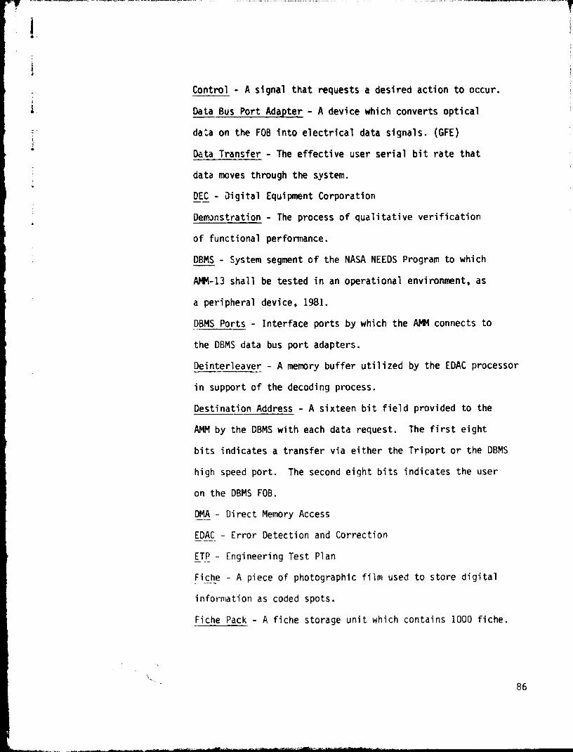
y
I
Control_- A signal that requests a desired action to occur.
Data Bus Port Adapter - A device which converts optical
data on the FOB into electrical data signals. (GFE)3
Data Transfer - The effective user serial bit rate that
data moves through the system.
DEC - Digital Equipment Corporation
Deporstration - The process of qualitative verification
of functional performance.
DBMS - System segment of the NASA NEEDS Program to which
AMM-13 shall be tested in an operational environment, as
a peripheral device, 1981.
DBMS Ports - Interface ports by which the AMM connects to
the DBMS data bus port adapters.
Deinterleaver - A memory buffer utilized by the EDAC processor
in support of the decoding process.
Destination Address - A sixteen bit field provided to the
AMM by the DBMS with each data request. The first eight
bits indicates a transfer via either the Triport or the DBMS
high speed port. The second eight bits indicates the user
on the DBMS FOB.
DMA - Direct Memory Access
EDAC - Error Detection and Correction
ETP - Engineering Test Plan
Fiche - A piece of photographic film used to store digital
information as coded spots.
Fiche Pack - A fiche storage unit which contains 1000 fiche.
86

Fiche Processor - The equipment that processes the
exposed fiche into a stable archival product.
FOB- - Fiber Optic Bus
Forward File Management - A process whereby records
are recorded in a predetermined location.
Frame Interleaving - A process which multiplexes 2048
bit frames of different requests into one output stream.
GFE - Government Furnished Equipment
Header - Within the AMM, the first 128 bits of a packet
of data.
ICD - Interface Control Document
Interleaver - A memory buffer utilized by the EDAC processor
in support of the encoding process.
Large Record - An y packet greater than 16,384 bits in length.
Mb/s_ - Megabits per sicond
MSFC - Marshall Space Flight Center
NEEDS - NASA End to End Data System
Operational Mode. - A demonstration procedure for verification
of joint AMM/DBMS performance.
Packet - A set of user data bits which starts with a header
and ends with a packet parity.
Ping-Pong Buffers - A set of buffers; one buffer receives
data while the other buffer transfers data, then vice-versa.
Prototype - An original model on which subsequent forms
are to be based. Intended to demonstrate the reduction
to practice of archival mass memory technologies.
87

Rate Buffer - A first-in first-out buffer utilized to
support asynchronous data transfer from a source to a
lower burst rate sink.
Request - A DBMS generated request for data stored in
the AMM. Requests consist of packet identification
information, number of the first byte within the packet
to be output, and the number of bytes to be output.
Small.- Record - Any packet less than or equal to 16,384
bits in length.
Status - A signal that conveys how well a control function
was executed or indicates a faulty event, function, or
equipment condition.
Sul?system - Any of the major software/hardware entities
comprising the AMM-13.
TBD - To Be Determined.
Test - The process of quantitative verification of functional
performance.
Tri_ort - A three ported memory block and controller which
is shared by the AMM. DBMS, and CMS VAX-11/780's.
User Data Rate - The effective rate at which dAta moves
to /from mass storage equipment with all overhead excluded.
88
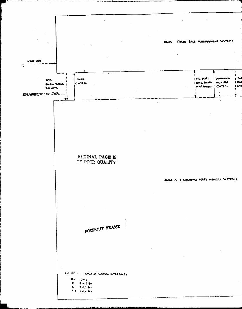
iAPAMV SYSTEM )
OMM! tarn W% NANACAInWt SYSRMI
IWWT me
^ ^ I
FO6 OATA ITRI-PORT COMMAND- I !
stAA1i /I.AR4! ICOWMOL IS+MU^ RcORO MpNIlpR I M
1ACUtTi tt
I rMlYT/^MtMtttt
GONTROt ^ FI
p^
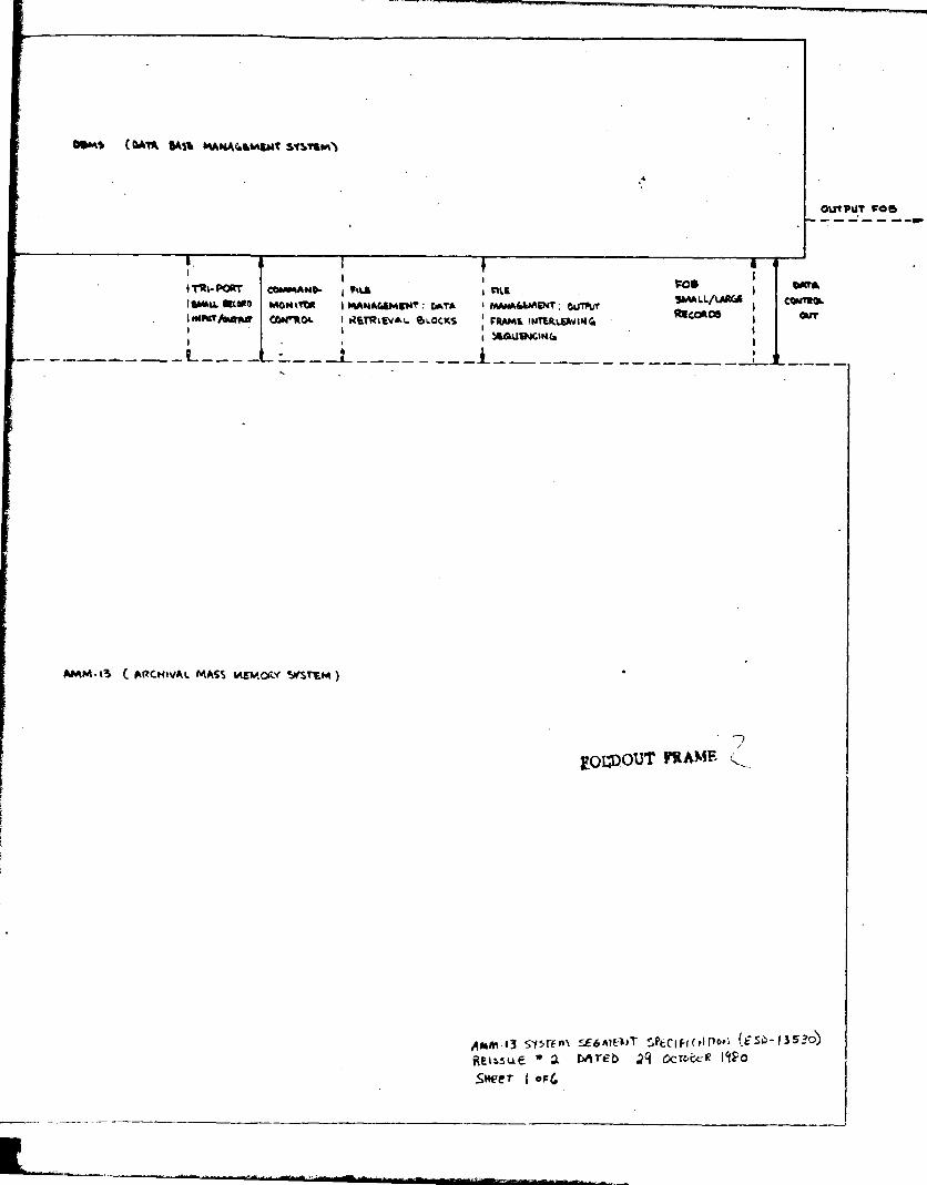
'YT FOS-----IW

- :{Coayoa
i sWA a I 1 1 09
""s t cwm GAS& MMNAA& INT SYSTifM7
%~ we
PCe 1 DWA
!MALL/LAItUt I CONT+IDL
OOAAtloOnj MCKlTS IN6p10ATOR ?lYL ILATL^ - -•
11
TR(-PORT I COMMAND- FILL 1 I:ljSMALL ftcmo I NbWlloa MWAr MaoINNRT^OYTILfT i CAN"44. 9AT•A I OLM
RnRIHAl 1 Aw( Y10CK! I INS
( 1
i
i
VAX GONPyrm SUBSYSTEM
Fos sMA_L RQcoao5 •Ho _ _ _ _LAW.& Racoao wtHDt^S
0COMM CowTaeL
I sk 11
_^11,/( -QATA CONTROL ^M 1 w ttm I^A1Rw aeconos .w I comrUm MARX) ' s
OrtA- - - - - - - - - - - - - -;
(uN+lul CONTR^ 1 A
1 ldN Co^T IIfTO.) I ' TttEAOQt
I
1 ® I ^
1 1
INPYT SUGSV%rIPA 1)
Oft' 'L?VAL PAGE LSOF ^?^'ji IW'T-',Ai,i^r
F"of Z . AMM-i; SySr&m/UfaYSrKlA iNTERFACtS
I Rtv Dkrt
1 0 e A U(o eo^-1 S oCT to• . 1 17 w b
AAUn- 1 3 sysTron sE-n lE►u7 S /EC^FicN^1.,^ [EsD /3S3o)REISSUE *., V 7Tb .29 oc7edr 9, 1980SjWer
L
RECOPrA
SUMYSTE

1 ( D*M MA W' AHOAKWAMT sysnm) J
WJTVNT FOS
FM 1 1 Gw+1AM101- Flu ' $ .% Fos ' DATAftCCA9 1 mmi-xiA M4Mt MiM' SMALLA AMA
I COM1R0./tutgrr CAM"4w oA'r^ 1 o1 rpa 1 fuCOADS our
^ MocK! ( IMtltlfAK, ^rI ^ 1 1
vAy. cOMPUrrx Sue3Y3rEw1COmMAwp- MGM IVOR (OMTROL I
• yMA ^_Rt GO fLO D+aIA^COwTRLt'^ _ _ — _ _ _ _ _ _ _ _ — 1© ND- MON I TOM (Owfl40L
Q # w^tCA CO*ZM16I 1
^ I
CAMTQOI. MWAM SMALL !
ow(Wi^M1! ^^ 1 QTe(,pR D^ ' I
c03r ' re AMr&x I
MADERIRfp) I ! !
It
^ I I^ 1 I
I I
4Gl ACA _ _ V[A^ _M.G R[CORO[OUT
i1JtlYit W SWSYSTEMdD
1
I
1
DntA IER 0491
LORTROG ^G
btR flRpOp 3RR42
ly
om it 011TH
COWM*L c COMTROI 1!o
RK +^1 Rtc +1
StL^fR/14t
RECORDER itltRtiYAIFICHEFICHEAYa "fit
Aux mrR
-SU65YSTEM eirl a SUBSYSTEM
O
I
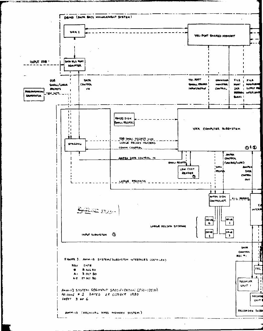
( CJ&MCS (DATA MS6 MANA4tMWT ylfT[M) - --- - - -.
1VAIL I
„ft-PGRT SNARiD MlMORY
I
i ' 1
1 ^, 1
INPUT F", "All1 0:3 bn 1
1 1I 1 , 1
me 1 0^T1► TRI -baT' 1 COMM AN► CitQ I FlliSWALLAA" I CONTROL leAALL nwA ` NMNtm MW 1 eylKAtiRAU(ETf I lee IM11^/wqr^ I CaNTReI 01►n► 1 Donut
R;1 UDOUNNw,-Tp^ o^r+ - - - I 1 R@MM v+RRI
I 1
I'
IIII RMOSOISK ------'---
^ 1 1 It RSLD^S)
11
1 1 VAX GOMrUTtR SL1AS`rSTEM11
COB SMALL RE(DROS AwpLARGO RECD!') HEAV t ,
aaCOMM_!DNTROI O TI
I I 1 AMP"AMPEX OATA COwTR I IM I
I CAMTROI
, ^ SiMAU RE I ^YN1^11S^»lTR)1
LOW COST Amft
,
READiR1ekoRMA DOM
I I COifiRDL1
I ^ - - - - - - - - - - - LJ► RbB- R^OR9S - - - - - - - - - - - - - - - - - 1O4T
I 1
i AN ►1X D^SM I A^ t - - -
INTERPG
lAR(s[ RE47^ 9TOItA6!
I ll'i" Sue&YS TW ^3
^314
I 1
CONTReI I1REC '^ 1 1
FI(^UR! 3. IMM•l5 SYS TEMlSUISYSTrzM t4rE g iACiS (C!*A,LlD)
1 RiV C^TQ,
• 8 Au(. to AEGA.I ?) AcT 6o
A •z n ocT 80 1
cu<(^+ucu 1
u\1IT 1 I
AMm- 13 SYSTE-h N SEbAlMr'$PrCIiICrlllc p,, L?SD-1350j iit*ISSU p ' Z DArFD :,Q CClodc! 1480 R
sxEE'r 3 •f G t1Nn•1
RECORDER 00AINM-15 (ARCHIVAL. MASS Mimoty SYST(M)

.LL R< OS V^IK ALL Rt COR OS O6ITONT
. -_- SLSSYl7 - -' --- - SuSSYS^
_LARGE RGCOROS-
11
ONM (Rc
WA
C^Tfi1L 1 G OMR^iI
' S#R • 2 ^ R1
y4R +1
11I
I
I
I1
AUK APR FICNE AUX XFR" - PROCESSOC^ -
REoLICATOc
1UNIT I I
1
SortUA: I r Z
J
1s/P a:e^^ ^TEI^ © I
TR=-PaR SIIARz MWAORr
1 I ^ , I1 1
'I
:oaMS elan *A RDRT C4v pL r We1
icsILR MMtT.) AOARfl -
1 11 , I 1
TRI-R^ 1 GOMMAN► FILE 1 • IFILL I
,1
1.w► Ricm 1 IINNlIOR M1rr1I MANA4tMWr , FO I OOR^
IM1Nr/OIIRIR CONTROL 4171 , Ou"Ur MIA& MIe6CAMA6 i COMT*OL1
,MAN INTSRwvlm(m
I
Rt[ORD! I alfr1 ILMS 1 ( 111
^I I
-- J iI
rRMOSI1
I
RILL 0461AT WIKtwm DISK
VAX COMWrak 3ussmevaM ------------1
916A M6MT) I. MMAND-MION I^OR -.C'N Tl It I I
SMAti R(CORO CONt40^ 1- -_ _ - - - - ,IwANO•MONI TOt OL
O M bAf)-- MON '_TOIL C.bJflE7\
I I1
1 AMP"
I II 1
1 ^1MIE11S^1MR)
LOW COST ^SMW ^^}
READER 'DOM
^ 1 tvinROL
our
^ 1
DISK IALL
LIO
IN r[R FAC g
O'ael [
DRIV! DTIIE I
1 ^ I
1DATA I Q DATA
CONTROL Cp COdTR.i.Ric *I I it R[C ^Z
I
SEC
REGpCKR
UNIT I ii
RECCwtEO
UNIT 2
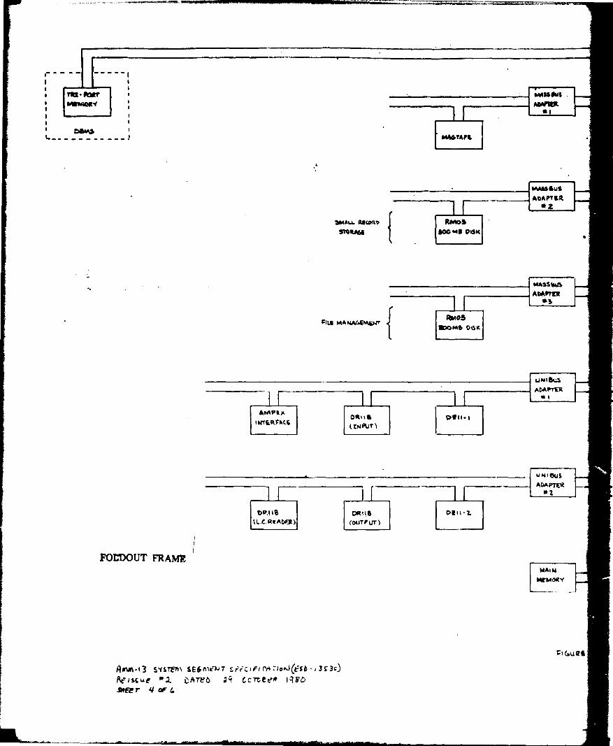
1TRt- ftwr
1 MItnA01tY ^1 ^
t ^
t DOKS ^
1-__--------_^
MAfitWt .ArItPR>R
1
MWAPt
4
MASS sus
^____ ADAP^[R
3MM66 "Wa ll) RNIOSsollAS^ soo Mr atslc
MASS W&ADA"U
as
FILE MANAaPALJrRwOS
'70MO OtSK
NNtbi;S
ADAPTERa t
AMPS T OR1ts Dfn-11f1r6R^'ACL(EF Ut)
uNtouSADAPTERri
oP.11e pule D;1t-2
llC.RFADO) (ouTVUT)
I
FOLDOUT FRAMEMAtN
MEMORY
V%GuQt^
AOW-13 5`ISTrwN SE^Atr-1+T S;F Ciif c`r ► Io^J^rSD- 3S3t^
Reiss u e "I ZATeb ;? GcTZteR 1480awe r 4 cF 6
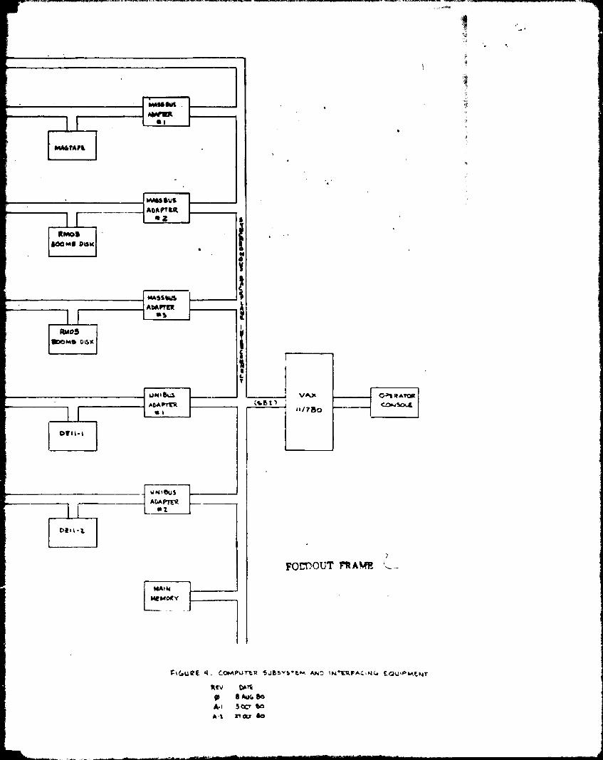
rlASSwt .IAA
1
M"TA►t
RMOsAwme DISK
itmos100040 "K
0111-1
MAssb1b
AUAPMs]
uNIMs
AMPTERo 1
WAU•usADAPT tRt2 s
N0
7}tR
1
LT
FOLTOUT FltAW
ovll•t
u N% Eui•e. vrro
r16uRE 4. COMPWrtR SJ6SY S'EM ANO IN'ERFAC,N^ [pL;iP-xNr
Rev DATE
m e AUG be
A-i 3 o En
A-% it Q7 60

' ^ YNtIL 1
1 ow►s ^
• 660" WON
' Rwl RMI
#Ara^ Oltl/lINft ^(%• IwNt fMka, Ri tURt 's 3^:.2 VlLbm t
1 11 ,NM
' fu^K>< 1pwTt wrw (
• 1
/
INPUT F'OG, • /
- - - - ^ t,MntR ^ -
_.^1 - •rti: •.. L1w TROY
1 1
t ^^ t , t
1 i
GusVr* at 111
t1 Mt RtWo.
R1f tlRe:
S. %A PO •ItSVS':N •.fl V'rAAC$ YfNT kJ USM1I• - -TREV DAlt --- —
O/ S Auws to t
461 & OLT bot
K >n o^
47 11
' tAh^•,j ly.+e^ti t[6Mrtil Ert*^•r,^e%,^.1(Et0•NSI^^ t
T — Ittltil •t deri0 all Oft t:cAti Sur 5 a (. t.

all
G"" WOOD SrGPJA4 t
*0 049 oat
• *43 low$
&ILL WAOVAA&~
OL
UWIO%;S
ArA-v i I
VAxOALWOk
C00 .11m,
MIW
Ip
A I
E^^ft
• ^ ILtettUOl . _ . _i
I LZI1,
^- 17^
-7p ^,A, --------- j

-_- -- ----------.-- -----
1 1
1. ret-^ ' 1• ^_ wwlouY I
1 WNL tt f •
1. - srw.L Rsme^
. sioaAic
R1(E b&4gk4w_ti:
AMVEII - - - -^ cal l a(INNT
1 _
11
-F 1 -
c 1 '
11 RtktOapb1 OV11^ OiCllb
• 1 lLG REAOVe) 11
1
1TI
-'
LIGU PS L, OuT/NT SLIdSrSTEM WlERFI1 ms 1 LOW COG r 1RN` E.R+3 r - -^--- 1. RuDCj 1d a AuG eo 1
^ ^^ 1 vER SK
rA-1 3ac? so 1 / SIl/fY3KM coMw,wO r.or , •--o CQ.00cx.Rt 17&r eo ------^
1 1
1 ALL R•ILOe0 1 1
1• 1 ii
' 1 1
11 , 11 . 1
r - - - - - - - y i do 1+.TcAlcA1 1. a_.-_----'----------► A!A
Q,ITF'uT FOB ^ C ►^A Nf Kr ' _3 __ OAtA • h^ Cov..lx
^ — - - -1 A:A ►TFR ^ — ^ _ — _. — _ —• 1 1 ^
1 11 V,J^S 1
i

e^^tA^
1
T COVtAh _
s nay
tL ^ r
'
^
OU"IA
waKI
M[q,
kASSSUiAOAOTQ
Kt
fMAtl Rita!"! RMOSstou" ;OOMR x151:
---- --r- rMASSO"ADA/TEZ
IL y^
ALL NANk •Ey _t: Ru10S►A' oeslc
r
11
A
Ur1E•1S
_^ f
ADRPfER _;
WW I& Dau-1 r
(I 4►ut)cc
VAX c>¢ x; rorrcse:^
- -- u ►1I Wsr---A ADAPTER
AWIN
PO Dour FRAME
TA
C --OT '
1 t
WD/MAN CT
(Y^TR CotrTla^
3^R
_.
CuT'NT VIC-I-TRrxt R[ oR ok
C^ShT[1SpROCESSID/
S IESYSTEM.G M D/MON [I\ RCau atTVtDATA C6017CO&
AU4ITL '- -^-
AAI n1-13 S y srtin Slbm,.jT V-clF,rr,r401D•!)OD).r^4 ccro^rr 14Yc14 R iN6YrST
Rclotte I Derr)LI^ SMtrT 6 CP 4
Top Related