


Languages
Pages
Legal

1
THERMOMECHANICAL BEHAVIOUR OF DRY CONTACTS IN DISC BRAKE ROTOR WITH A GREY CAST IRON
COMPOSITION
Ali.Belhocine *, Mostefa.Bouchetara * Laboratory of Mechanics Applied, Faculty of Mechanical Engineering, University of Sciences and the
Technology of Oran, L.P 1505 El -MNAOUER, USTO 31000 ORAN (Algeria) Email* : [email protected]
The main purpose of this study is to analysis the thermomechanical behavior
of the dry contact between the brake disc and pads during the braking phase.
The simulation strategy is based on the calculation code ANSYS11. The
modeling of transient temperature in the disk is actually used to identify the
factor of geometric design of the disk to install the ventilation system in
vehicles. The thermal-structural analysis is then used coupling to determine
the deformation established and the Von Mises stresses in the disk, the
contact pressure distribution in pads. The results are satisfactory compared to
those found in the literature.
.Key words: Brake discs, Heat flux, Heat transfer coefficient, Von Mises
stress, contact pressure
1. Introduction
The braking process is in fact the matter of energy balance. The aim of braking system is to
transform mechanical energy of moving vehicle into the some other form, which results by decreasing
of vehicle speed. The kinetic energy is transformed into the thermal energy, by using the dry friction
effects and, after that, dissipated into the surroundings [1]. have developed for a few decades at
intervals raised in many sectors :nuclear power, space, aeronautical, automobile, petro chemistry, etc
[1].
In 2002, Nakatsuji et. al. [2] did a study on the initiation of hair-like cracks which formed
around small holes in the flange of one-piece discs during overloading conditions. The study showed
that thermally induced cyclic stress strongly affects the crack initiation in the brake discs. In order to
show the crack initiation mechanism, the temperature distribution at the flange had to be measured.
Using the finite element method, the temperature distribution under overloading was analyzed. 3D
unsteady heat transfer analyses were conducted using ANSYS. A 1/8 of the one piece disc was divided
into finite elements, and the model had a half thickness due to symmetry in the thickness direction. In
2000, Valvano & Lee [3] did a study on the technique to determine the thermal distortion of a brake
rotor. The severe thermal distortion of a brake rotor can affect important brake system characteristics
such as the system response and brake judder propensity. As such, the accurate prediction of thermal
distortions can help in the designing of a brake disc. In 1997, Hudson & Ruhl [4] did a study on the air
flow through the passage of a Chrysler LH platform ventilated brake rotor. Modifications to the
production rotor’s vent inlet geometry are prototyped and measured in addition to the production
rotor. Vent passage air flow is compared to existing correlations. With the aid of Chrysler Corporation,

2
investigation of ventilated brake rotor vane air flow is undertaken. The goal was to measure current
vane air flow and to improve this vane flow to increase brake disc cooling. Rise resulting from the
temperature can strongly influence the properties of surface of materials in slip, support
physicochemical and microstructural transformations and modify the rheology of the interfacial
elements present in the contact [ 5 ]. Recent numerical models, presented to deal with rolling processes
[6,7] have shown that the thermal gradients can attain important levels which depend on the heat
dissipated by friction, the rolling speed and the heat convection coefficient .Many other works [8-9]
dealt with the evaluation of temperature in solids subjected to frictional heating. The temperature
distribution due to friction process necessitates a good knowledge of the contact parameters. In fact,
the interface is always imperfect – due to the roughness – from a mechanical and thermal point of
view. Recent theoretical and experimental works [10-11] have been developed to characterise the
thermal parameters which govern the heat transfer at the vicinity of a sliding interface. In certain
industrial applications, the solids are provided with surface coating. A recent study has been carried
out to analyse the effect of surface coating on the thermal behavior of a solid subjected to friction
process [12]. In creased thermal efficiency and the integrity of materials in high-temperature
environments is an essential requirement in modem engineering structures in, automotive, aero space,
nuclear, offshore, environmental and other industries. Nowadays, the finite element method is used
regularly to obtain numerical solutions for heat transfer problems. The most common choice when
using finite elements is standard Galerkin formulation [13]
In this work, we will make a modeling of the thermomechanical behavior of the dry contact
between the disc of brake pads at the time of braking phase, the strategy of calculation is base on the
software Ansys 11 [14]. This last is elaborate mainly for the resolution of the complex physical problems. The numerical simulation for the coupled transient thermal field and stress field is carried
out by sequentially thermal-structurall coupled method based on Ansys.
2. Heat flux entering the disc
In the case of disc brake, the effective friction processes between the pads and the disc are
extremely complex due to the fact that the present time brake pads, due to their composite structure
[15], do not have constant chemical-physic proprieties, the organic contained elements being subject
of a series of transformations under the influence of temperature increase. The heat distribution
between the brake disc and the friction pads is mostly dependent on material characteristics, among
whom a major influence is due to the density [kg/m3], the thermal conductivity [W/m.K]
and the specific heat [J/kg.K] of disc’s (index d) and braking pad’s materials respectively (index
p). Denoting and [J] the heat quantities assumed by the disc and the braking pads respectively,
one could be expressed in the following manner [16]
Because the braking disc is not entirely covered by the friction pads, within computing we
have to consider the ratio between the disc surface and the pads surface . Denoting the ratio of
heat’s division between the disk and pads with:

3
and considering Q [J] the heat quantity generated during the friction process, the heat
quantities assumed by the pads and by the disc are:
The brake disk assumes the most part of the heat, usually more than 90% [17], through the
effective contact surface of the friction coupling. Considering the complexity of the problem and
average data processing limited, one replaced the plates by their effect, represented by an entering heat
flux ( Fig.1) .
.The initial heat flux q0entering the disc is calculated by the following formula [18]:
Where gaz = : Braking effectiveness,a : Deceleration of the vehicle [ms-2],φ : Rate
distribution of the braking forces between the front and rear axle,Ad : Disc surface swept by a brake
pad [m2], v0 : Initial speed of the vehicle [ms-1] ε p
: Factor load distribution of the on the surface of
the disc.,m : Mass of the vehicle [kg] , g : Acceleration of gravity ( 9.81 ) [ms-2].
Fig.1. Application of flux
The loading corresponds to the heat flux on the disc surface. The dimensions and the
parameters used in the thermal calculation are recapitulated in Tab1.

4
Table 1. Geometrical Dimensions and application parameters of automotive braking
Inner disc diameter, mm 66
Outer disc diameter, mm 262
Disc thickness (TH) ,mm 29
Disc height (H) ,mm 51
Vehicule mass m , kg 1385
Initial speed v0 , km/h 28
Deceleration a , m/s2 8
Effective rotor radius Rrotor ,mm 100.5
Rate distribution of the braking forces Φ , % 20
Factor of charge distribution on the disc ε p 0.5
Surface disc swept by the pad Ad, mm2 35993
The disc material is gray cast iron ( GFC) with high carbon content [19], with good thermophysical
characteristics and the brake pad has an isotropic elastic behavior whose thermo- mechanical
characteristics adopted in this simulation in the of the two parts are recapitulated in Tab 2.
Table 2.Thermoelastic properties used in simulation
Material Properties Pad Disc
Thermal conductivity,, k (w/m.°C) 5 57
Density, (kg/m3) 1400 7250
Specific heat, c (J/Kg. °C) 1000 460
Poisson.s ratio,, 0,25 0,28
Thermal expansion, (10-6 / °C) 10 10,85
Elastic modulus,, E (GPa) 1 138
Coefficient of friction, 0,2 0,2
Operation Conditions
Angular velocity, (rd/s) 157.89
Hydraulic pressure,, P (MPa) 1
3.Thermal analysis of the problem
Transient heat conduction in three dimensional heat transfer problem is governed by the
following differential equation [20]
5
Where qx, qy and qz are conduction heat fluxes in the x, y and z-directions, respectively, Cp is
the specific heat, ρ is the specific mass, Q is internal heat generation rate per unit volume and T is the
temperature that varies with the coordinates as well as the time t. The conduction heat fluxes can be
written in the form of temperature using Fourier's law. Assuming constant and uniform thermal
properties, the relations are:
Where kx, ky and kz are thermal conductivity in the x, y and z-directions, respectively. Heat
transfer boundary conditions consist of several heat transfer modes that can be written in different
forms. The boundary conditions frequently encountered are as follows [21, 22]:
Where T1 is the specified surface temperature; qs the specified surface heat flux (positive into surface);
h the convective heat transfer coefficient; Ts the unknown surface temperature, and T∞ the convective
exchange temperature.
4. Modeling in ANSYS CFX
The finite volume method consists of three stages; the formal integration of the governing
equations of the fluid flow over all the (finite) control volumes of the solution domain. Then
discretisation, involving the substitution of a variety of finite-difference-type approximations for the
terms in the integrated equation representing flow processes such as convection, diffusion and sources.
This converts the integral equation into a system of algebraic equations, which can then be solved
using iterative methods [23]. The first stage of the process, the control volume integration, is the step
that distinguishes the finite volume method from other CFD methods. The statements resulting from
this step express the ‘exact’ conservation of the relevant properties for each finite cell volume. This
gives a clear relationship between the numerical analogue and the principle governing the flow.
To enable the modeling of a rotating body (in this case the disc) the code employs the rotating
reference frame technique. The solution scheme employees the κ-ε model with scalable wall function
and sequential load steps. For the preparation of the mesh of CFD model, one defines initially, various
surfaces of the disc in ICEM CFD as the figure 2 shows it, we used a linear tetrahedral element with
30717 nodes and 179798 elements. In order not to weigh down calculation, an irregular mesh is used
in which the meshs are broader where the gradients are weaker (not-uniform mesh), (Fig. 3).
The CFD models were constructed and were solved using ANSYS-CFX software package
[24]. The models employ periodic boundary conditions on the segmented sides; and the radial and
axial lengths of the air domain surrounding the disc. The disc is modelled attached to an adiabatic
shaft whose axial length spans that of the domain. Air around the disc is considered at T∞=20 ° C and

6
open boundaries with zero relative pressure were used for the upper, lower and radial ends of the
domain ( Fig.4)
Fig 3. Definition of surfaces of the ventilated disc Fig.2. Irregular mesh in the wall
Fig.4 Brake disc CFD model
The values of the coefficient of exchange will be taken average values calculated by the
minimal and maximum values obtained using ANSYS CFX POST as it east indicates on the Fig.5.
Air at 20 °C
Disc
Input
Symmetric wall air
Adiabatic wall air
Outlet
SSYM1
SF1
SF2
SV21
SV22
SV23
SF2
ST2
SV4
ST4 ST3
SC2 SC1
SC3 SPV4
SPV2
SPV3
SSYM1 SC2
7
Fig.5 Distribution of heat transfer coefficient on a ventilated disc in the stationary case (FG 15).
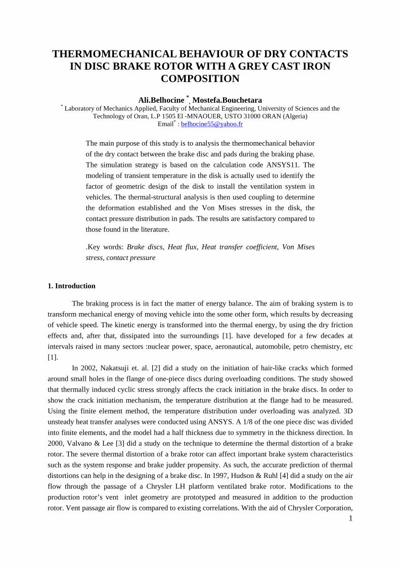
a) Results of the calculation of the coefficient h
-0.5 0.0 0.5 1.0 1.5 2.0 2.5 3.0 3.5 4.0
0102030405060708090
100110120
SC1 SC2 SC3 SC4 SF1 SF3 ST2 ST3 ST4 SV1 SV2 SV3 SV4
Coe
ffici
ent o
f tra
nsfe
r h
[W.m
-2.°
C-1]
T im e [s]
Fig.6 Variation of heat transfer coefficient (h) of various surfaces for a full disc in the non stationary case (FG 15)

8
-0 .5 0 .0 0 .5 1 .0 1 .5 2 .0 2 .5 3 .0 3 .5 4 .00
2 5
5 0
7 5
1 0 0
1 2 5
1 5 0
1 7 5
2 0 0
2 2 5
2 5 0
S C 1 S C 2 S C 3 S F 1 S F 3 S P V 1 S P V 2 S P V 3 S P V 4 S T 1 S T 2 S T 3 S T 4 S V 1 S V 2 S V 3 S V 4C
oeffi
cien
t of t
rans
fer
h [W
m-2 °
C-1]
T im e [s ]
The comparison between figures 6 and 7 concerning the variation of heat transfer coefficient
to the non stationary mode for the two types of design full and ventilated, one notes that the
introduction of the system of ventilation influences directly the value of this coefficient for same
surface what is logically significant because this mode of ventilation intervenes in the reduction in the
difference in temperature wall-fluid. 5. Meshing of the disc
The elements used for the mesh of the full and ventilated disc are tetrahedral three-dimensional elements with 10 nodes (isoparamitric) (fig. 8).
(a) full disc (b) ventilated disc
(172103 nodes -114421 elements) (154679 nodes- 94117 elements)
Fig.8 Meshing of the disc
6. Initials and boundary conditions
The boundary conditions are introduced into module ANSYS Workbench [ Multiphysics ], by Choosing the mode of simulation first of all (permanent or transitory), and by defining the physical properties of material.These conditions constitute the initial
Fig. 7 Variation of heat transfer coefficient (h) of various surfaces for a ventilated disc in transient case (FG 15)
9
conditions of our simulation.After having fixed these parameters, one introduces a boundary condition associated with each surface
� Total time of simulation = 45 [s]
� Increment of initial time = 0.25 [s]
� Increment of minimal initial time = 0.125 [s]
� Increment of maximal initial time = 0.5 [s]
� Initial Temperature of the disc = 60 [°C]
� Materials: Grey Cast iron FG 15.
� Convection:One introduces the values of coefficient of transfer of heat (h) obtained for each surface in the shape of a curve (fig. 6, 7),
� Flow:One introduces the values obtained of flow entering by code CFX.
7. Results and discussions
7. 1. Influence of construction of the disc
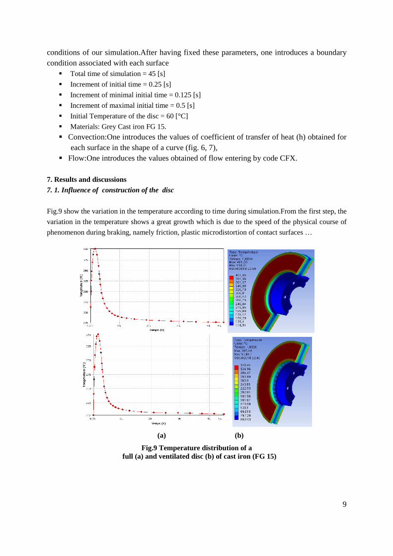
Fig.9 show the variation in the temperature according to time during simulation.From the first step, the
variation in the temperature shows a great growth which is due to the speed of the physical course of
phenomenon during braking, namely friction, plastic microdistortion of contact surfaces …
(a) (b)
Fig.9 Temperature distribution of a full (a) and ventilated disc (b) of cast iron (FG 15)

10
For the full disc ,the temperature reaches its maximum value of 401,55 °C at the moment t =
1,8839 s, then it falls quickly until 4,9293 s, as from this moment and until the end t = 45 s) of
simulation the variation in the temperature become slow. It is noted that the interval [0-3,5] s
represents the phase of forced convection. From the latter, one is in the case of the free convection
until the end of simulation. In the case ventilated disc one observes that the temperature of the disc
falls approximately 60 C compared to the first case. It is noted that ventilation in the design of the
discs of brake gives a better system of cooling.
8.Coupled Thermo-Mechanical Analysis
8.1. FE model and boudary conditions
A commercial front disc brake system consists of a rotor that rotates about the axis of a wheel,
a caliper–piston assembly where the piston slides inside the caliper, which is mounted to the vehicle
suspension system, and a pair of brake pads. When hydraulic pressure is applied, the piston is pushed
forward to press the inner pad against the disc and simultaneously the outer pad is pressed by the
caliper against the disc [25]. Numerical simulations using the ANSYS finite element software package
were performed in this study for a simplified version of a disc brake system which consists of the two
main components contributing to squeal the disc and the pads. Various boundary conditions in
embedded configurations imposed on the model (disc-pad), taking into account its environment direct,
are respectively the simple case as shown in Fig.14.The initial temperature of the disc and the pads is
20 °C and the surface convection condition is applied at all surfaces of the disc with the values of the
coefficient of exchange calculated previously and the convection coefficient (h) of 5 W/m2.°C is
applied at the surface of the two pads. The heat flux into the brake disc during braking can be
calculated by the formula described in the first part. The FE mesh is generated using three-dimensional
tetrahedral element with 10 nodes (solid 187) for the disc and pads. There are about 185901 nodes and
113367 elements are used (Fig.15). The thermal coupling will be carried out by the thermal condition
at a temperature nonuniform all takes the thermal environment of the model of it, For this reason, the
order " thermal condition " will be used to deal with the thermomechanical coupled problem and to
manage the transient state.
Fig.14 Boundary conditions Fig.15 Refined mesh of the model and loading imposed on the disc-pads
11
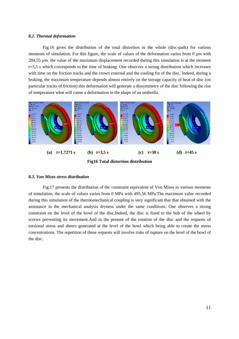
8.2. Thermal deformation
Fig.16 gives the distribution of the total distortion in the whole (disc-pads) for various
moments of simulation. For this figure, the scale of values of the deformation varies from 0 µm with
284,55 µm. the value of the maximum displacement recorded during this simulation is at the moment
t=3,5 s which corresponds to the time of braking. One observes a strong distribution which increases
with time on the friction tracks and the crown external and the cooling fin of the disc. Indeed, during a
braking, the maximum temperature depends almost entirely on the storage capacity of heat of disc (on
particular tracks of friction) this deformation will generate a dissymmetry of the disc following the rise
of temperature what will cause a deformation in the shape of an umbrella.
(a) t=1,7271 s (b) t=3,5 s (c) t=30 s (d) t=45 s
Fig16 Total distortion distribution
8.3. Von Mises stress distribution
Fig.17 presents the distribution of the constraint equivalent of Von Mises to various moments
of simulation, the scale of values varies from 0 MPa with 495,56 MPa.The maximum value recorded
during this simulation of the thermomechanical coupling is very significant that that obtained with the
assistance in the mechanical analysis dryness under the same conditions. One observes a strong
constraint on the level of the bowl of the disc.Indeed, the disc is fixed to the hub of the wheel by
screws preventing its movement.And in the present of the rotation of the disc and the requests of
torsional stress and sheers generated at the level of the bowl which being able to create the stress
concentrations. The repetition of these requests will involve risks of rupture on the level of the bowl of
the disc.

12
(a) t=1,7271 s (b) t=3,5 s (c) t=30 s (d) t=45 s
Fig. 17 Von Mises stress distribution.
8.4. Contact pressure
Fig.18 shows the contact pressure distribution in the friction interface of the inner pad taken
for at various times of simulation.For this distribution the scale varies from 0 MPa with 3,3477 MPa
and reached a value of pressure at the moment t=3,5 s which corresponds to the null rotational speed.It
is also noticed that the maximum contact pressure is located on the edges of the pad of the entry and
goes down towards the exit from the area from friction. This pressure distribution is almost
symmetrical compared to the groove and it has the same tendency as that of the distribution of the
temperature because the highest area of the pressure is located in the same sectors. Indeed, at the time
of the thermomechanical coupling 3d, the pressure carries out to lead to the not-axisymmetric field of
the temperature. This last affects thermal dilation and leads to a variation of the contact pressure
distribution .
(c) t=1,7271 s (b) t=3,5 s (c) t=40 s (d) t=45 s
Fig.18 Contact pressure distribution in the inner pad
13
9. Conclusion
In this publication, we presented the analysis of thermomechanical behavior of the dry contact
between the brake disc and pads during the braking process; the modeling is based on the ANSYS
11.0. We have shown that the ventilation system plays an important role in cooling disks and provides
a good high temperature resistance.
The analysis results showed that, temperature field and stress field in the process of braking phase
were fully coupled. The temperature, Von Mises stress and the total deformations of the disc and
contact pressures of the pads increases as the thermal stresses are additional to mechanical stress
which causes the crack propagation and fracture of the bowl and wear of the disc and pads. Regarding
the calculation results, we can say that they are satisfactory commonly found in the literature
investigations. it would be interesting to solve the problem in thermo-mechanical disc brakes with an
experimental study to validate the numerical results.
References
[1] Milenković, P. D. et.al. , Milenković, P. D. et.al.: The influence of brake pads thermal conductivity on passanger car brake system efficiency , Thermal Science: Year 2010, Vol. 14, Suppl., pp. S221-S230
[1] H.Belghazi, Analytical solution of unsteady heat conduction in a two-layered material in imperfect contact subjected to a moving heat source, Phd Thesis, university of Limoges, 2010. [2] T Nakatsuji, K Okubo, T Fujii, M Sasada, Y Noguchi (2002) Study on Crack Initiation at Small Holes of One- piece Brake Discs. Society of Automotive Engineers, Inc 2002- 01-0926 [3] T Valvano & K Lee (2000) An Analytical Method to Predict Thermal Distortion of a Brake Rotor. Society of Automotive Engineers, Inc 2000-01-0445 [4] M D Hudson & R L Ruhl (1997) Ventilated Brake Rotor Air Flow Investigation. Society of Automotive Engineers, Inc 1997-01-033 [5] Denape. J, Laraqi. N, Aspect thermique du frottement: mise en évidence expérimentale et éléments de modélisation, Mecanique & Industries, N°1, pp. 563-579, (2000). [6] M. Hamraoui, Thermal behaviour of rollers during the rolling process, Applied Thermal Engineering, 29 (11-12) (2009) 2386-2390 [7] M. Hamraoui, Z Zouaoui, Modelling of heat transfer between two rollers in dry friction, International Journal of Thermal Sciences, 48 (6) (2009) 1243-1246 [8] N. Laraqi, Velocity and relative contact size effect on the thermal constriction resistance in sliding solids, ASME J. Heat Transfer, 119 (1997) 173-177. [9] H. Yapıcı, M.S. Genç, G. Özısık, Transient temperature and thermal stress distributions in a hollow disk subjected to a moving uniform heat source, Journal of thermal stress 31(2008) 476-493. [10] N. Laraqi, N. Alilat, J.M. Garcia-de-Maria, A. Baïri, Temperature and division of heat in a pin-on-disc frictional device – Exact analytical solution, Wear, 266 (7- 8) (2009) 765-770. [11] J.G. Bauzin, N. Laraqi, Simultaneous estimation of frictional heat flux and two thermal contact parameters for sliding solids, Numerical Heat Transfer 45 (4) (2004) 313-328. [12] A. Baïri, J.M. Garcia-de-Maria, N. Laraqi, Effect of thickness and thermal properties of film on the thermal behavior of moving rough interfaces, European Physical Journal –
14
Applied Physics, 26 (1) (2004) pp. 29-34. [13] Mijuca, D. M., @iberna A. M., Medjo B. I.: a new multifield finite element method in steady state heat analysis . Thermal Science: Vol. 9 (2005), No. 1, pp. 111-130
[14] Lele Zhang, Qiang Yang, D. Weichert , Nanlin Tan. Simulation and Analysis of Thermal Fatigue Based on Imperfection Model of Brake Discs, Beijing Jiaotong University , PAMM · Proc. Appl. Math. Mech. 9, 533 – 534 (2009)
[15] Fiche U.I.C . 541-3 : FREIN – Frein à disques et garnitures de frein à disques, 4e
édition, 01.07.1993.
[16] Saumweber , E., Temperaturberechnung in Bremsscheiben fürein beliebiges
Fahrprogramm, Leichtbau der Verkehrsfahrzeuge , Heft 3 /1969, Augsburg.
[17] Cruceanu , C., Frâne pentru vehicule feroviare ( Brakes for railway vehicles ), Ed.
MATRIXROM, Bucureşti, 2007, ISBN 978-973-755-200-6, 388 pag.
[18] Reimpel J.: Technologie de freinage. Vogel Verlag, Würzburg, 1998.
[19] Gotowicki, Pier Francesco ; Nigrelli , Vinzenco ; Mariotti, Gabriele Virzi. 2005.
Numerical and experimental analysis of a pegs- wing ventilated disk brake rotor ,
with pads and cylinders, 10 th EAEC European Automotive Congress – Paper
EAEC05YUAS04– P 5, June 2005.
[20] Yu, H., et al.: study on temperature distribution due to freezing and thawing at the fengman
concrete gravity dam , thermal science, year 2011, vol. 15, suppl. 1, pp. s27-s32 [21] Sergerlind, L. J., Applied Finite Element Analysis, John Wiley and Sons, New York, USA, 1984 [22] Hinton, E., Owen, D. R. J., An Introduction to Finite Element Computations, Pineridge Press Limited, UK, 1981 [23] H K Versteeg & W Malalasekera – An Introduction to Computational Fluid Mechanics, The Finite Volume Method
[24] Ansys v.11 user’Manual guide .
[25] M. Nouby and K. Srinivasan .Parametric Studies of Disc Brake Squeal using Finite Element
Approach” Anna University Chennai-600025 India.Jurnal Mekanikal. December 2009, No.29,
52-66
Authors’ affiliations Ali.Belhocine (corresponding author) Department of Mechanical Engineering, University of Sciences and the Technology of Oran , L.P 1505 El -MNAOUER, USTO 31000 ORAN ,Algeria E-mail: [email protected] Mostefa.Bouchetara (professor) Laboratory of Aeronautics and Propelling Systems,,Department of Mechanical Engineering, University of Sciences and the Technology of Oran, L.P 1505 El -MNAOUER, USTO 31000 ORAN ,Algeria E-mail: [email protected]
Top Related