


Languages
Pages
Legal


The Republic of Uganda
MINISTRY OF HEALTH
Health Infrastructure Division
Operation Manual for Regional Medical Equipment Maintenance
Workshops and Medical Equipment Maintenance Guidelines
A guide for Regional Workshop and Hospital Technicians
December 2013
1
Table of Contents
Forward ····································································· 4
Acronyms ····································································· 6
Chapter 1: Introduction ····················································· 8
1.1 Background
1.2 Overall Objectives
1.3 Specific Objectives
1.4 Stakeholders in Medical Equipment Maintenance
1.5 Definition of Medical Equipment Maintenance
Chapter 2: Organization Structure for Medical Equipment
Maintenance ·················································· 13
2.1 NACME
2.2 Health Infrastructure Division (HID)
2.3 Regional Medical Equipment Maintenance
Workshops (RWs)
2.4 National Referral Hospitals
2.5 Regional Referral Hospitals (RRHs)
2.6 District Health Services
Chapter 3: Function, Operation and Role of RWs ················ 18
3.1 Central Medical Equipment Maintenance Workshop
3.2 Regional Medical Equipment Maintenance
Workshops

2
Chapter 4: Planning, Budgeting and Management of Medical
Equipment Maintenance ·································· 21
4.1 Medical Equipment Inventory Update
4.1.1 Inventory taking Rules and Procedure
4.2 Work Plan and Budgeting for Medical Equipment
Maintenance
4.2.1 Process of Preparation of Annual Work Plans and
Budgets
4.2.2 Preparation of RW Annual and Quarterly Budget
4.2.3 Preparation of Quarterly Maintenance Schedules
4.2.4 Budgeting for Emergency Works
4.3 Management of Medical Equipment Maintenance
4.3.1 Preparation of Quarterly Reports
4.3.2 Workshop Managers’ Meetings
4.3.3 Regional Workshop Management Committee
4.3.4 Internal Workshop Staff Meetings at Workplace
Chapter 5: Procurement and Disposal of Goods and Services by
RWs ····························································· 32
5.1 Management of Procurement by RWs
5.1.1 Determination of Spare Parts Needs
5.1.2 Procedure of Purchasing Spare Parts
5.1.3 Stores Management by RWs
5.2 Disposal of Un-Necessary Items
Chapter 6: Support Supervision, Monitoring and Evaluation of
RWs ····························································· 37
6.1 Support Supervision Policy for RWs

3
Chapter 7: Guidelines for Medical Equipment Maintenance ···· 39
7.1 Introduction
7.2 Planned Preventive Maintenance
7.3 Corrective Maintenance Services
7.4 Maintenance Policy
7.5 Levels of Maintenance
7.6 Range of Medical Equipment that can be maintained
by RWs or Outsourcing
7.7 Setting up a Maintenance System
7.7.1 Routine Maintenance Procedures and Work Flow
Charts
7.7.2 Personnel
7.7.3 Reminder System
7.7.4 Surveillance
7.7.5 Standard Maintenance Work Formants
7.7.6 Special Test Equipment
7.7.7 Technical Library
Chapter 8: Periodical Maintenance Checklist for Common
Equipment (32 types of Equipment) ··················· 48
Annexes ································································· 114
Annex 1: Standard Floor Plan of a Regional Workshop
Annex 2: Recommended WS Tools, Test Equipment and
Furniture
Annex 3: Stickers Form, Equipment Condition A-F
Annex 4: Medical Equipment Inventory Form
Annex 5: Template of Work Plan Preparation
Annex 6: 5S Activity’s Instruction for RWs
Annex 7: Quarterly Report General Form
Annex 8: Job Card Form
Annex 9: Support Supervision & Monitoring Sheet
Annex 10: Complaints Form

4
Foreword
The main mission of the Ministry of Health is to ensure provision
of comprehensive Healthcare Services to the Ugandan
population and the Government is committed to ensuring
efficient, safe and effective Healthcare delivery.
A substantial proportion of the Health Sector budget is spent on
acquisition of Medical Equipment.
To ensure that available Medical Equipment safely serves for a
long time, it must be managed efficiently. The way in which it is
used and maintained may greatly affect its reliability and hence
the quality of Healthcare delivered to patients.
Appropriate periodic/preventive and corrective maintenance is
key to achieving safe and cost-effective management of
medical equipment. It is important therefore that measures are
taken to ensure that medical equipment is maintained and cared
for by the Healthcare workers in order to maximize the
investment made in its acquisition. For effective maintenance to
be carried out by the maintenance team, adequate operation
and maintenance funds should be budgeted and allocated.
This manual helps to streamline the operations of the Regional
Medical Equipment Maintenance Workshops. Additionally, the
Maintenance guidelines will facilitate first line Maintenance to be
undertaken by both the Users’ of the equipment and technicians
in a well structured and safe manner.
This manual is an essential reference book for the Regional
Medical Workshops to plan, manage and execute basic
maintenance using the prepared guidelines; and ensure
5
adequate and proper maintenance of most common essential
Medical Equipment.
I am pleased to write the foreword to this first ever operational
workshop manual for RWs in Uganda. I also recommend the
use of this manual to our health workers to carry out User
Training and first line maintenance in Health Facilities.
I would like to acknowledge and thank JICA for supporting the
preparation of this manual and Eng. D.M.K. Katesigwa for
providing technical guidance during its drafting.
Special recognition goes to Mr. Naoki Mimuro, Mr. Shigetaka Tojo
and Eng. Sitra Mulepo C.S for their dedication and Technical input
to produce this manual.
Lastly, I would like to extend my appreciation to the staff of the
Health Infrastructure Division, Members of NACME and HI_TWG
for their oversight and editorial role during the preparation of this
manual.
I have no doubt that this manual will facilitate better
maintenance of medical equipment by the RWs in our Health
Facilities. .
Dr. Jane Ruth Aceng
Director General Health Services

6
Acronyms
List of Acronyms
5S Five steps of Sort, Set, Shine, Standardize and
Sustain
AC Alternating Current
ACHS(HI) Assistant Commissioner, Health Infrastructure
Division, Clinical Services Department
AEO Assistant Engineering Officer
BP Blood Pressure
CD4 Cluster of Differentiation 4
CO2 Carbon Dioxide
CT Computerized Tomography
CW Central Medical Equipment Maintenance
Workshop
DC Direct Current
DHOs District Health Officers
DPA Disposal Public Asset
ECG Electrocardiogram
ENT Ear, Nose and Throat
HC Health Centre
HGB Hemoglobin
HID Health Infrastructure Division
HI_TWG Health Infrastructure Technical Working Group
HIV Human Immunodeficiency Virus
HMIS Health Management Information System
JICA Japan International Cooperation Agency
LCD Liquid Crystal Display
LED Light Emitting Diode
ME Medical Equipment
MoFPED Ministry of Finance, Planning and Economic
Development
MOH Ministry of Health
7
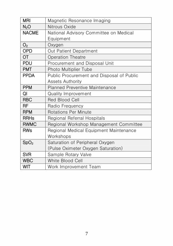
MRI Magnetic Resonance Imaging
N2O Nitrous Oxide
NACME National Advisory Committee on Medical
Equipment
O2 Oxygen
OPD Out Patient Department
OT Operation Theatre
PDU Procurement and Disposal Unit
PMT Photo Multiplier Tube
PPDA Public Procurement and Disposal of Public
Assets Authority
PPM Planned Preventive Maintenance
QI Quality Improvement
RBC Red Blood Cell
RF Radio Frequency
RPM Rotations Per Minute
RRHs Regional Referral Hospitals
RWMC Regional Workshop Management Committee
RWs Regional Medical Equipment Maintenance
Workshops
SpO2 Saturation of Peripheral Oxygen
(Pulse Oximeter Oxygen Saturation)
SVR Sample Rotary Valve
WBC White Blood Cell
WIT Work Improvement Team

8
Chapter 1: Introduction
1.1 Background
Medical equipment plays an important role in our Health Care
system and there are numerous equipment adapted to Health
Care. In the health facilities, medical equipment will range from
injection needles, centrifuges, stethoscopes, blood pressure
machines, to X-Ray Machines, MRI etc. designed to help
medical personnel carry out diagnosis and treatment of patients.
Optimal performance of medical equipment is required to ensure
safety, accuracy and expected results. To keep medical
equipment in good working condition and optimal performance
is the function of a medical equipment maintenance unit in a
health facility.
The Ministry of Health set up Regional Medical Equipment
Maintenance Workshops to carry out medical equipment
maintenance in health facilities. In the hospitals, there are
different engineering personnel deployed to man hospital
maintenance units. They carry out maintenance and repair on
medical equipment.
This operation manual is intended to support and guide
engineering personnel in the RWs and Hospital maintenance
units in the maintenance of basic medical equipment. It will also
guide the equipment users and technicians on the operation and
working principles of some commonly used equipment.
9
1.2 Overall Objective
The overall objective of preparing this manual is to define the
roles of RWs and other stakeholders; and provide guidelines on
medical equipment maintenance management including
maintenance planning, budgeting, training and disposal of
medical equipment.
1.3 Specific Objectives
The specific objectives of this manual are:
• To define the role and function of RWs and Central
Medical Equipment Maintenance Workshop
• To identify and define the roles of various stakeholders
• To streamline the operations of RWs and CW
• To develop maintenance guidelines for commonly used
medical equipment in health care facilities.
• To prepare equipment specific Maintenance Guidelines to
ensure safety, proper use, care and management of
medical equipment.
1.4 Stakeholders in Medical Equipment Management
The following categories of health care workers and providers
play a significant role in the maintenance of medical equipment.
• Users of medical equipment
This category involves doctors, nurses and paramedics
whose primary function is to use medical equipment for
diagnosis and treatment of patients. Their main role will

10
be to care for the equipment including reporting
equipment failure to the maintenance unit.
• Medical equipment maintenance personnel
This category includes artisans, technicians and engineers
employed by health facilities to offer maintenance
services for equipment. Their main role is to identify and
isolate the fault, and take remedial action to restore full
functionality of the medical equipment.
• Hospital administrative staff
This category includes the hospital administrators,
procurement personnel, accounts personnel and other
staff responsible for safe custody of hospital stores. This
category is involved in planning, assets/stores
management, procurement of spares, and financial
management.
• Medical equipment manufacturers and vendors
The role of this category is to offer spare parts for the
equipment they manufacture or sell and offer After Sales
Services including contract maintenance services for
specialized equipment.
11
1.5 Definition of Medical Equipment Maintenance
Medical equipment maintenance refers to a set of activities
conducted on a medical equipment to keep it in optimum
working. It is divided into two major categories namely:
• Planned Preventive Maintenance (PPM)
This refers to regular safety and performance inspection
carried out on medical equipment to evaluate risk and
reduce failure so as to enhance its safety, efficiency and
reliability.
It involves cleaning, regular function/safety tests and
making sure that any problems are picked up before they
cause a breakdown.
PPM is recommended for most of the medical equipment.
It will enhance the efficiency, effectiveness and reliability
of medical equipment and must be carried out at
appropriate frequency as suggested by the manufacturer
or workload.
• Corrective Maintenance (or repair)
Corrective maintenance is a task performed to identify
and rectify a fault on a broken down equipment, machine
or system to restore to it to its original operational
condition.

12
The choice of approach for preventive and corrective
maintenance depends on the complexity of equipment,
equipment usage and/or cost benefit analysis by the in-
house trained technician. The majority of equipment in
our health care system is basic in nature and can be
handled in-house by any technician or artisan at RW level.
For specialized and advanced equipment, the vendor
should provide maintenance services through a
combination of on-call services and a maintenance
contract negotiated at the time of purchase. Maintenance
contracting should be reserved for medical equipment for
which there is no in-house capacity to maintain or when
specialized equipment and technical expertise is needed
to be economically viable to develop this capacity in-
house.
13
Chapter 2: Organization Structure for Medical
Equipment Maintenance
There is a wide range of medical equipment at different levels of
the health care delivery system. The staffs in these Health
Facilities are responsible for ensuring that it is used and stored
properly and faulty equipment is reported to departments
responsible for maintenance.
At the central level, the Unit directly responsible for the
management of medical equipment is the Health Infrastructure
Division (HID) under the Clinical Services Department. The
National Advisory Committee on Medical Equipment is mandated
to give appropriate clinical and technical advice to MOH
regarding medical equipment.
At District and Health facility levels, the management of medical
equipment is the responsibility of the respective Administrative
and Technical Departments. The District Health Officers (DHOs)
are directly responsible for planning and management of
medical equipment in the District Local Governments.
For medical equipment, RWs established under Regional Referral
Hospitals (RRHs) carry out medical equipment maintenance;
while the HID of the MoH oversees supervision of maintenance
activities.
2.1 National Advisory Committee on Medical Equipment
(NACME)
The main function of NACME is to review the country’s medical
equipment needs and determine the appropriate policy
framework.
14
This includes advising on procurement, standardization,
maintenance and rehabilitation of medical equipment, bearing in
mind cost-effectiveness and appropriateness of technology.
2.2 Health Infrastructure Division (HID)
The division has two major sections with the mandate to
formulate policies and guidelines on health infrastructure
development and management.
The sections are:
1) Civil Engineering Section
2) Electro-Mechanical Engineering Section
1) Civil Engineering Section
All building and Civil Engineering in the Sector are
coordinated by this section. It provides support and
supervision of pre-installation works and ensuring that fixed
medical equipment is installed safely.
2) Electro-Mechanical Engineering Section
This section encompasses the electrical and mechanical
engineering disciplines. The electrical and mechanical
engineering professionals are responsible for preparing
specifications and ensuring that procured equipment
conforms to national and international standards; and that
the equipment is appropriate and maintainable.
Some of the activities related to medical equipment in this
section include:
15
i) Supervision and monitoring the management of the
complete life cycle of medical equipment and
furniture in public health facilities.
ii) Acting as the Secretariat to NACME and take care of
the executive work for the committee. Preparation of
the standard equipment lists and update of
specifications is handled by the Electrical/Mechanical
Engineers.
i) Specification and quantification of equipment for
procurement in the health sector.
ii) Organizing training from time to time so as to ensure
that technicians and engineers keep abreast with the
fast changing trends in Biomedical engineering.
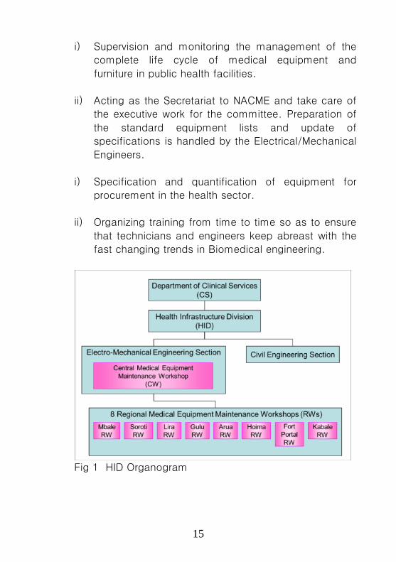
Fig 1 HID Organogram

16
2.3 Regional Medical Equipment Maintenance Workshops
(RWs)
In order to decentralise medical equipment maintenance, the
MOH established RWs at RRHs to maintain medical equipment in
health facilities under their catchment area.
To date there are nine (9) RWs located at Arua, Lira, Gulu, Soroti,
Mbale, Hoima, Fort Portal, Kabale RRHs and Central Medical
Equipment Maintenance Workshop, Wabigalo in Kampala.
The Central Medical Equipment Maintenance Workshop (CW)
was established under HID and is a referral workshop for all
other RWs.
Fig 2 Location and Catchment Areas of RWs
* CW: Central Medical Equipment Maintenance Workshop * RW: Regional Medical Equipment Maintenance Workshop
*
*
*
*
**
*
*
*
HOIMA RW
FORT PORTAL RWCW
(WABIGALO)
MBALE RW
SOROTI RW
LIRA RW
GULU RWARUA RW
KABALE RW
KAMPALA

17
2.4 National Referral Hospitals (NRHs)
At the National Referral Hospital level, the Engineering and
Administration Departments are responsible for equipment
management. The Hospitals have a fully-fledged Engineering
Department that works independent of the RWs.
2.5 Regional Referral Hospitals (RRHs)
At RRHs, the management of medical equipment is the
responsibility of the Hospital Administrator and respective RW
Manager. While the RWs are part of the Hospitals, they have
responsibilities to maintain medical equipment in all the health
facilities in their catchment area. This is one of the outreach
services of the RRHs.
2.6 District Health Services
At the District level, the management of medical equipment is
the responsibility of the DHO and the respective in-charges of
the Health Facilities. District Engineers in Local Governments
assist the DHO to plan for health infrastructure development and
management.
Staffing levels for medical equipment maintenance in Districts is
still quite low. There is also a country wide shortage of
Biomedical Engineering human resource in both private and
public health institutions. The RWs support health facilities in
the relevant districts to carry out periodical maintenance and
repair of medical equipment.
18
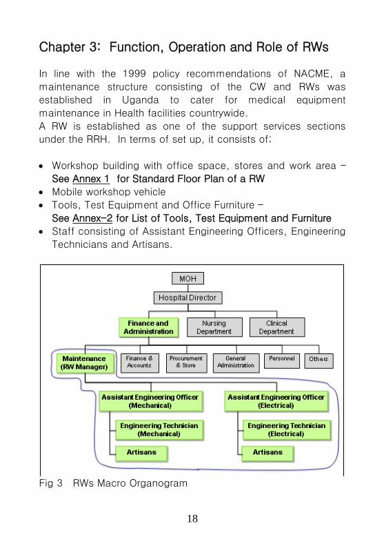
Chapter 3: Function, Operation and Role of RWs
In line with the 1999 policy recommendations of NACME, a
maintenance structure consisting of the CW and RWs was
established in Uganda to cater for medical equipment
maintenance in Health facilities countrywide.
A RW is established as one of the support services sections
under the RRH. In terms of set up, it consists of;
• Workshop building with office space, stores and work area –
See Annex 1 for Standard Floor Plan of a RW
• Mobile workshop vehicle
• Tools, Test Equipment and Office Furniture –
See Annex-2 for List of Tools, Test Equipment and Furniture
• Staff consisting of Assistant Engineering Officers, Engineering
Technicians and Artisans.
Fig 3 RWs Macro Organogram

19
Operationally, the teams of technicians from the RW visit
Hospitals, DHO’s stores and HCIV to carry out equipment
maintenance on site. For HCII and HCIII, the faulty medical
equipment is delivered to the DHO’s stores or HCIV by the In-
charge of the HC for the workshop team to carry out
maintenance. On a case by case basis, the RW team may visit
a HCII or HCIII to repair immovable equipment like a generator,
solar system.
3.1 Central Medical Equipment Maintenance Workshop,
Wabigalo (CW)
The CW located in Kampala is the RW for Health facilities for the
Central region and a referral workshop. It is also acts as a
training centre for Hospital based technicians. Other roles and
functions of the CW include the following:
i) Supervision of all RWs through the Electro-Mechanical
Engineering Section of HID focusing on maintenance and
repair activities, review of work plans and budgets; and
quarterly reports.
ii) Identification of suitable service providers and guidance on
procurement of spare parts.
iii) Plan for capacity development activities for all regional
workshops. This involves human resource development,
mentorship.
iv) Support other RWs to carry out and update medical
equipment inventory.

20
3.2 Regional Medical Equipment Maintenance Workshops
The RWs are based at the RRH and cater for maintenance of
medical equipment in health facilities within the catchment area.
While day to day supervision of the operations of RWs is under
the Administration of the RRH, each workshop has a RW
Management Committee that over sees its operations. The RW
Management Committee consists of members from all
beneficiary hospitals and the District and Health Sub-District
Authorities.
The main functions of RWs include the following:
i) Maintenance of medical equipment in all health facilities in
their catchment area.
ii) Medical equipment inventory update in all health facilities in
their region.
iii) Advise hospital managers on medical equipment disposal.
iv) Preparation of quarterly equipment maintenance reports for
submission to ACHS(HI)
v) Organizing and participating in the Regional Workshop
Management Committee (RWMC) Meetings.
vi) Organizing User Training for equipment Users in proper use,
handling and first line maintenance.

21
Chapter 4: Planning, Budgeting and Management of
Medical Equipment Maintenance
Lack of medical equipment maintenance results in break down
and prolonged down time affects the reliability and quality of
health care. Lack of a maintenance policy can result in poor
planning, lack of maintenance budgets and thus no spares parts
and accessories. Many health facilities suffer because the
maintenance requirements are not planned for in advance. This
renders much equipment unusable and many devices lie idle
because of lack of spares parts or funds.
The staff of the RWs and CW are responsible for planning and
budgeting for maintenance activities. For day to day duties, the
RW staff are responsible to the Hospital Director and Hospital
Administrator. At Ministry level they are supervised by the Senior
Engineer (Medical Equipment) based at HID, Wabigalo in
Kampala.
The following activities will promote effective maintenance
planning and management:
i) Regular medical equipment inventory taking and update
ii) Prepration of annual/quarterly work plans and budgets
iii) Preparation of maintenance schedules
iv) Preparation of maintenance reports including quarterly and
annual performance reports
v) Holding regular workshop and regional workshop
management committee meetings

22
4.1 Medical Equipment Inventory Update
The Workshop manager shall endeavor to keep and update an
inventory of all medical equipment in each health facility. Proper
entry should be made in the inventory database. The inventory
record should contain the following details:
i) Name of health facility and date of inventory taking
ii) Equipment Name
iii) Manufacturer (with contact details where possible)
iv) Serial No. of equipment or allocated identification No.
v) Location of equipment in health facility (e.g. OPD,
Maternity)
vi) Date/Year of Installation/purchase.
vii) Current maintenance status “Condition A-F”
– see Annex 3
Medical inventory taking should be carried out in August of every
year. Inventory update however, should be done when new
equipment has been procured, or equipment has been
transferred from one location to another.
4.1.1 Inventory taking Rules and Procedure
An accurate inventory is important for proper maintenance
planning and scheduling. It should be carried out in good
time to inform decision making on equipping gaps,
disposal and budgeting. The following methodology shall
be followed when carrying out inventory:
23
Visit each department and section of the hospital and
record available equipment against the user’s
inventory record if available.
Carry out a physical count and inquire whether the
quantity is adequate.
Consult the user on operational status (i.e. whether
the equipment is operational or not)
Record all required information as detailed in the
Medical Equipment Inventory Form - See Annex 4
The Workshop Manager in consultation with the hospital
staff should identify equipment that is due for
decommissioning and disposal.
4.2 Work Plan and Budgeting for Medical Equipment
Maintenance
In order to plan for maintenance activities the Workshop
Manager should prepare a work plan and budget. The work plan
should have an itemized summary of planned activities, targets,
timelines and intended expenditure on a quarterly basis. The
work plan and budget should indicate the proposed source of
funding.
Adequate time should be allocated for procurement of goods
and services including spare parts. The standard templates for
preparation of work plans should be used
– see Annex 5 _ for Template of Work Plan Preparation.
Currently, medical equipment is maintained using resources from
the National budget, Local Governments through the health
facilities and Development Partners.
24
4.2.1 Process of Preparation of Annual Work Plans and Budgets
The budgeting process starts in October of every year
when the MoFPED sends out a budget call circular.
Each RRH makes an annual work plan and the RW work
plan and budget is part of it. The RRH submits the work
plan and budget to MOH for onward submission to
MoFPED which makes budgetary allocation for various
Ministries and/or Departments
During this time, the Workshop Manager should prepare
and submit the RW priorities and budget requirements to
the Hospital Director for incorporation in the overall work
plan for the RRH.
4.2.2 Preparation of RW Annual and Quarterly Budget
Since funds are disbursed to RWs on a quarterly basis;
planned activities should be scheduled across the year in
a logical manner. Identify routine activities that are
repetitive and spread them across each quarter and add
other activities that can be carried out in the available
time and allocated funds for each quarter. While it is
usually normal to divide the annual budget allocation by 4,
it is important to critically look at the processes and
inputs (i.e. time, human resources and finances) needed
to realize planned activities.
The RW budget should provide for the following:
i) Procurement of spare parts and maintenance
workshop supplies
ii) Labour cost including outsourced services

25
iii) Mobile workshop operational costs (i.e. fuel, tyres,
servicing and repair)
iv) Subsistence costs while on maintenance trips (i.e. Per
diem, lunch allowances)
v) RWMC Meetings
vi) Workshop Managers Meetings
vii) Training for users and workshop technicians
viii) Replacement of essential tools and consumables
ix) Office stationery and supplies
x) Maintenance of office equipment
xi) Payment for telephone, water and electricity bills.
4.2.3 Preparation of Quarterly Maintenance Schedules
As one of the planning tools, each RW will prepare a
quarterly maintenance schedule. The maintenance
schedule will identify the Health facilities to be visited,
allocated time and human resources.
The quarterly schedule shall be prepared after confirming
the available funds and prioritized planned activities for
the quarter.
The RW manager shall send out the maintenance
schedule in good time to allow the Health facility
managers plan and mobilize the staff to avail the
equipment that needs maintenance.
The maintenance schedule should be followed as much
as possible by the RW to ensure efficiency and cost
effectiveness.
26
4.2.4 Budgeting for Emergency Works
There will always be cases of critical equipment breaking
down and the RW would be expected to respond
immediately. To cater for such incidences, a contingency
(10% to15% of the overall quarterly budget allocation)
should be provided for in the quarterly work plan to cater
for emergency callouts. The contingency funds should be
spent on a case by case basis on express approval of the
RRH Director; and can be drawn from the petty cash and
replenished immediately.
4.3 Management of Medical Equipment Maintenance
In the management of RW operations and Equipment
Maintenance, it is important to involve stakeholders especially
the Users and Administrators. This will help each player to have
a good understanding of WHAT to do, WHEN to do it, WHO is to
do what; and to agree on the necessary MEANS to do it.
The following scheduled reports and meetings will provide
opportunities for engagement and sharing experiences and
challenges of medical equipment management:
• Quarterly reports
• Workshop Managers’ meetings
• RWMC meetings
• RW Staff meetings
RWs will implement 5S activities designed to improve the work
environment, safety, and work flow. This Manual has a
summarized description of 5S implementation steps for the
workshop environment and it is attached at Annex 6. The
detailed description of 5S implementation can be found in the
5S Hand Book and Implementation Guidelines produced by MOH.

27
4.3.1 Preparation of Quarterly Reports
The Workshop Manager shall prepare and submit
Quarterly Reports to the ACHS(HI) through the Hospital
Director every 15th day of the months of April, July,
October and January of each year.
The quarterly report shall highlight the overall progress in
implementation of planned activities and performance.
The quarterly report will contain the following:
Planned activities and status of implementation
Summary of medical equipment maintained at each
health facility
Expenditure during the quarter clearly separating
expenditure on spare parts, per diem, workshop
operational costs (i.e. electricity, water,
communication as necessary), labour, and vehicle
maintenance,
Planned activities and expenditure for the next quarter.
Challenges met
Conclusion
Recommendations
A proposed format for preparing quarterly reports is
attached at Annex 7 for Quarterly Report General Form
All Job Cards for work carried out in the standard format
should be attached - See Annex 8

28
4.3.2 Workshop Managers’ Meetings
The Managers of RWs will always meet to discuss issues
relating to Medical Equipment Maintenance and
Management of RWs.
Purpose of meeting
The Workshop Managers Meeting will be a forum where
all the Workshop managers meet and share experiences,
challenges and chart a way forward to improve
maintenance of medical equipment in their regions.
Frequency
The ACHS(HI) through the CW shall organize a
Workshop Managers’ meeting at least twice a year at the
CW or any other RW agreed upon by the members.
Participants
The Workshop Managers’ meeting will include all RWs
Managers, senior staff of CW and the HID responsible
for medical equipment management and other
stakeholders as shall be deemed fit from time to time
(e.g. manufacturers’ representatives, equipment vendors,
Hospital Administrators).
4.3.3 Regional Workshop Management Committee (RWMC)
In order to bring together all stakeholders, each RW shall
hold a RWMC meeting at least twice a year in December
and April.
Purpose
The RWMC meeting will be a forum where stakeholders
come together to share experiences and evaluate the
performance of the RW. The work plan, budget and

29
maintenance schedules will be reviewed and approved
for each year and/or quarter. The meeting will be
chaired by District/Hospital hosting the meeting while the
RW will be secretariat for the meeting.
Frequency
The RWMC meeting shall take place at least twice a year
to coincide with the review of the quarterly/annual report
prepared by the workshop Manager.
Recommended participants
The following stakeholders will constitute the RWMC
membership:
Medical Superintendents/Hospital Administrators of
the beneficiary Hospitals
DHOs of the beneficiary Districts
25% of the Heads of Health Sub-Districts on a
rotational basis
Workshop Manager
Representative of HID/MOH
Proposed Agenda for RWMC Meeting
The following Agenda is proposed for the meeting:
Call to order and opening prayer
Adoption of Agenda
Self-introduction
Communication from the Chair
Review of minutes of previous meeting and maters
arising
Report on maintenance activities by the Workshop
Manager including quarterly work plan and budget
30
Comments and matters arising from the Workshops
Managers Report
Submission of relevant issues from the various
participants.
Comment by a representative of ACHS(HI)
Issues at Hand and Way Forward
Note: The meeting should always review the proposed
work plan, schedule and budget for next
quarter/year.
4.3.4 Internal Workshop Staff Meetings at workplace
RWs are manned by a Workshop Manager and other
technicians in the RRH. To ensure cohesion and
coordination in the RW, the workshop manager will hold
regular internal meetings with other staff. The RW
Manager will use these meetings to discuss action plans,
allocate work and review progress and challenges.
Frequency
Internal meetings between the workshop manager and
his /her staff should take place on a daily/weekly basis
to ensure clarity on the tasks to be performed on a daily,
weekly and/or monthly basis.
Discussion points
Relevant tasks and timelines should be discussed and
agreed upon by all staff members.
Meeting Minutes and Work Reports
The Workshop manager will put in place a mechanism
to ensure that action points agreed upon in the internal
meeting are documented and followed up.

31
Each staff shall prepare a one page report on the tasks
he/she undertook for the day/week and the overall
status of the task.
Minutes of all meetings held shall be prepared and filed
for future reference. Making of Minutes shall be a shared
responsibility by all staff of the workshop on a rotational
basis including the workshop manager.
Note:
1. Daily meetings should last not more than 30 Minutes
2. Meetings held on Weekly basis should not last more
than 1 hour

32
Chapter 5: Procurement and Disposal of Goods and
Services by RWs
While RWs will get involved in procurement and disposal of
medical equipment; this is not their core function. This is the
function of the respective Heads of the Health facilities and the
Procurement and Disposal Units (PDU). Their role in medical
equipment procurement should be limited to;
• Review and/or provision of technical specifications
• Inspection and testing to confirm conformity to contract
technical specifications and functionality
• Installation and commissioning
• Recommending medical equipment for decommissioning
and disposal based on technical considerations (e.g. age,
obsolescence, lack of spare parts, reliability and safety).
For day to day workshop operations, the RWs will be involved in
procurement of medical equipment spare parts and maintenance
services. In this case, the workshop staff will be involved in
procurement processes as a User Department.
5.1 Management of Procurement by RWs
Procurement of spare parts and services by RWs will be guided
by the Public Procurement and Disposal of Public Assets
Authority (PPDA), the Regulation thereto and guidelines in force.
All RW managers need to acquaint themselves with PPDA
guidelines and the different procurement methods. Regional
workshops will be responsible for planning for spare parts needs
(i.e. quantification, specifications and budget), out sourcing
maintenance services on a case by case basis and disposal of
spare parts that are not useful.

33
As a User Department, the RW will play the following
procurement roles;
i) Determine and quantify workshop requirements
ii) Propose/provide technical specifications for the required
supplies
iii) Raise procurement requisitions using the Procurement
Form PP 20
iv) Participate in the selection of supplies and service
providers
v) Participate in inspection, testing and verification of
supplies.
Note:
1. RW staff must exercise high moral and ethical conduct
while handling procurement of goods and services
2. No supplies should be used before they are taken on
charge in the stores and issued out.
5.1.1 Determination of Spare Parts Needs
Determination of spare parts needs shall be based on
demonstrated maintenance needs and requirements for
Planned Preventive Maintenance (PPM).
Problem oriented planning and budgeting will be the basis
for maintenance planning and scheduling to ensure
efficient and cost effective utilization of available
resources.
• Medical equipment inventory for each health facility
will be analyzed to determine the maintenance
condition of the equipment. Repair carried out will
always be supported with a Job Card Form – see
Annex 8.
34
• RWs will endeavor to print serialized Job Cards and
enforce the preparation of Equipment breakdown
Report Forms (HMIS Form 11) by health facilities.
• A list of fast moving spare parts will be prepared and
used to determine quarterly requirements. Where
possible a list of fast moving spare parts for each
equipment will be developed from time to time.
5.1.2 Procedure for Purchasing Spare Parts
Procurement of spare parts and tools shall be in
accordance with the PPDA guidelines. The RW will
identify and quantify the spare parts requirements, and
raise the Procurement requisition to start the procurement
process through the PDU.
While the RW would allow the PDU to manage the
procurement process, it is advisable for the RW manager
to assist the PDU to identify possible suppliers and
appropriate procurement method. This is important
because of the specialized nature of medical equipment
spare parts.
• Some spare parts are manufacturer specific and
direct procurement would be the most efficient and
cost effective procurement method.
• Also, prequalification of suppliers would help reduce
the time needed to identify and place orders.
Framework contracts could be entered into with
prequalified suppliers.

35
Whatever procurement method is used, it is important
that the process is transparent, fair, efficient and cost
effective.
5.1.3 Stores Management by RWs
RWs have stores and must maintain inventory records.
Management of all stores (i.e. tools and spare parts)
shall be in accordance with standard stores management
practices. The RW shall secure and maintain stores
“Stock cards”, “Stores Requisition Forms” and “Stores
Issue Forms”.
Stock cards shall be maintained weekly, while monthly
stock taking will be carried out for all inventories. No
spare part shall be issued out without clearly identifying it
(i.e. name, part number and model).
5.2 Disposal of Un-necessary Items
Disposal is part of the procurement process and must be
planned for. The life cycle of any equipment ends with
disposal; but it is often difficult for users to decide when to
decommission and how to dispose of equipment.
The reasons for decommissioning and disposal of equipment will
include:
Wear beyond economic repair
Damage beyond economic repair
Unreliability
Safety
Clinical or technical obsolescence
Unavailability of spare parts
36
Availability of more cost-effective equipment or clinical
procedure or technology
Once items for disposal are identified, the PPDA guidelines and
procedure should be followed. The disposal process would
include;
A) Identification of items to dispose of
B) Submission of list of items for approval by the Accounting
Officer (i.e. Hospital Director and/or Hospital Board).
C) Establishment of a Board of Survey team to approve list
of items for disposal.
D) Initiation of disposal process through preparation and
submission of disposal requisition DPA Form 120 to the
PDU to start the disposal process.
Note: The role of the RW will be advisory as the Accounting
Officer/PDU has the mandate to dispose of assets/stores.
37
Chapter 6: Support Supervision, Monitoring and
Evaluation of RWs
The Quality Assurance Department of MOH is responsible for
monitoring and evaluation of healthcare services. This is done
through the Area Teams which assess and monitor
implementation of various policy guidelines, planned activities
and performance against Sector indicators.
The Evaluation and Monitoring assessment form for Area Teams
includes Health Infrastructure and RW staffs need to provide the
information on medical equipment maintenance and its impact
on healthcare delivery.
6.1 Support Supervision Policy for RWs
For the RWs, specific support supervision will be conducted by
the HID/Clinical Service Department and focus will be put on the
following;
• Maintenance planning and budgeting. Evidence based
planning and budgeting should be the basis for budget
allocation.
• Availability of adequate spare parts. Stock planning and
control should ensure that essential medical equipment is
well maintained at all times.
• Efficiency and cost effectiveness. Operational costs
should be optimized to a minimum level but with high
outputs and outcomes.
• Prudent financial management and planning. Maintenance
scheduling and resource allocations should be optimized to
ensure efficiency and cost effectiveness.
• Equipment down time and response time. The response
time to emergency calls for repair of life support equipment
should not be more than 24hours. The PPM schedule

38
should aim at keeping at least 65% of the essential
medical equipment in good maintenance condition.
1) Frequency of visits
The HID will carry out support supervision and monitoring
of RWs once every quarter.
A standard monitoring sheet has been designed to
assess RWs - see Annex 9 for Support Supervision &
Monitoring Sheet.

39
Chapter 7: Guidelines for Medical Equipment
Maintenance
7.1 Introduction
The main objective for any maintenance system is to ensure
prolonged use of available equipment to provide safe and
reliable healthcare over its design life.
All RWs shall ensure proper maintenance of medical equipment
to sustain the intended healthcare benefits and to preserve
capital investments. To achieve this, medical equipment shall be
maintained in working order and periodically calibrated to ensure
accurate results.
To ensure efficient maintenance of equipment, RWs will plan
and budget for maintenance under two main categories:
• Planned Preventive Maintenance
• Breakdown maintenance
7.2 Planned Preventive Maintenance (PPM)
PPM is usually scheduled at specific intervals and includes
specific maintenance activities such as lubrication, calibration,
cleaning of filters or replacement of spare parts that are
expected to wear out after stipulated time or workload (e.g.
bearings, tubings).
All RWs shall endeavor to implement PPM and scheduling based
on the principle of “Problem oriented maintenance planning and
budgeting” to optimize utilization of the limited funds and human
resources.

40
Effective planning for preventive maintenance will involve careful
selection of the equipment to be included in the plan. Evidence
based decisions must be made while deciding equipment to
include in the maintenance schedule in order to reduce costs.
Maintenance planning shall always ensure that essential medical
equipment for basic diagnosis, infection control, surgery and
treatment are kept in good working condition. The overriding
considerations will always be safety, efficiency and cost
effectiveness.
7.3 Corrective Maintenance Services
Corrective maintenance refers to corrective actions undertaken in
the event of breakdown of a piece of equipment. In this case,
the equipment is repaired or calibrated after failure.
At all times, medical equipment in use should be free from any
fault regardless of how minor the fault is and all repair work
should be performed by a competent technician.
The user department should:
1) Record details of the defect
2) Fill-in a “Complaint Form”. Refer to Annex 10.
3) Contact the RW technician who should in turn decide
whether to carry out the repairs or to contact the
maintenance contractor.
4) Ensure that information regarding equipment breakdown
is passed to all staff during shift change and the head of
the institution.
All equipment breakdown occurring in the wards should be
recorded on the Complaint Form mentioned above.

41
7.4 Maintenance Policy
The choice of implementing Preventive or Corrective
Maintenance depends on the complexity of equipment,
availability of After Sales service and cost.
Maintenance of medical equipment by the RWs will be based on
PPM for all essential medical equipment that can be handled by
RWs; and a mix of PPM and Corrective maintenance for medical
equipment that need outsourcing the maintenance services.
Equipment maintenance shall be carried out by both In-House
trained technicians and Manufacturer’s representatives or Vendor.
For specialized and advanced equipment, the RWs will on a
case by case basis outsource maintenance services through a
combination of on-call services and a maintenance contract
negotiated at the time of equipment purchase.
7.5 Levels of Maintenance
For purposes of this Manual, three levels of maintenance will be
observed:
Level 1: First-line by the Equipment User
This refers to maintenance activities that can be carried out
by the user or health facility based technician. This will
include dusting equipment, cleaning filters, checking fuses
and checking power supply source without opening the unit
and without moving it away from the point of use.
Other first line maintenance activities could include the
following:

42
Equipment decontamination and sterilization
Functional checks
Calibration checks
Safety checks
Note: First line maintenance may be carried out by Hospital
based Technicians too.
Level 2: By Technician
This refers to maintenance carried out by a technician when
first-line maintenance cannot rectify a fault or when a
regular scheduled check and calibration is due.
Level 3: Specialized Maintenance by Technician/Engineer from
Manufacturer’s representative/Vendor
This refers to maintenance activities that need higher level
technical expertise, troubleshooting techniques and tools.
Equipment such as X-Ray machine, CT Scanners,
Ultrasound scanner, Endoscope, Automatic Laboratory
Analyzer etc. need specialized engineers and technicians
who have been trained to maintain this specific equipment.
Additionally, specialized tool/equipment may be required for
testing and calibration of such equipment. This caliber of
Technicians/Engineers is normally employed by third party
companies or vendors representing the manufacturer of the
equipment.
This manual focuses on level 1 (user or first-line
maintenance) and level 2 (technicians level) maintenance.
For purposes of this manual, level 2 maintenance shall be
largely provided by the RW technicians except for cases
where Maintenance Contracts exist.
43
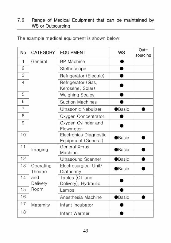
7.6 Range of Medical Equipment that can be maintained by
WS or Outsourcing
The example medical equipment is shown below;
No CATEGORY EQUIPMENT WS Out-
sourcing
1 General BP Machine ●
2 Stethoscope ●
3 Refrigerator (Electric) ●
4
Refrigerator (Gas,
Kerosene, Solar) ●
5 Weighing Scales ●
6 Suction Machines ●
7 Ultrasonic Nebulizer ●Basic ●
8 Oxygen Concentrator ●
9
Oxygen Cylinder and
Flowmeter ●
10
Electronics Diagnostic
Equipment (General) ●Basic ●
11 Imaging
General X-ray
Machine ●Basic ●
12 Ultrasound Scanner ●Basic ●
13 Operating
Theatre
and
Delivery
Room
Electrosurgical Unit/
Diathermy ●Basic ●
14 Tables (OT and
Delivery), Hydraulic ●
15 Lamps ●
16 Anesthesia Machine ●Basic ●
17 Maternity Infant Incubator ●
18 Infant Warmer ●
44
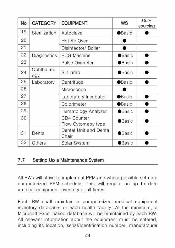
No CATEGORY EQUIPMENT WS Out-
sourcing
19 Sterilization Autoclave ●Basic ●
20 Hot Air Oven ●
21 Disinfector/ Boiler ●
22 Diagnostics ECG Machine ●Basic ●
23 Pulse Oximeter ●Basic ●
24 Ophthalmol
ogy Slit lamp ●Basic ●
25 Laboratory Centrifuge ●Basic ●
26 Microscope ●
27 Laboratory Incubator ●Basic ●
28 Colorimeter ●Basic ●
29 Hematology Analyzer ●Basic ●
30
CD4 Counter,
Flow Cytometry type ●Basic ●
31 Dental Dental Unit and Dental
Chair ●Basic ●
32 Others Solar System ●Basic ●
7.7 Setting Up a Maintenance System
All RWs will strive to implement PPM and where possible set up a
computerized PPM schedule. This will require an up to date
medical equipment inventory at all times.
Each RW shall maintain a computerized medical equipment
inventory database for each health facility. At the minimum, a
Microsoft Excel based database will be maintained by each RW.
All relevant information about the equipment must be entered,
including its location, serial/identification number, manufacturer
45
details and maintenance record. A reference number should be
engraved on each equipment. Additional information that should
be captured includes:
• Whether equipment is maintained in-house, or
• Maintained by external agency or manufacturer
7.7.1 Routine Maintenance Procedures and Work Flow Charts
As much as possible, PPM activities to be conducted on
each equipment shall be laid out in a workflow chart or
check list. The specific work to be carried out may be
based on guidance from the manufacturer’s
maintenance/service manual.
• The frequency of maintenance shall be based on the
manufacturer’s recommendation or usage.
• A heavily used equipment must be cleaned and
checked more frequently than one which is used less
often. Minimum standards must be met to ensure
safety and reliability.
7.7.2 Personnel
Maintenance of equipment will be undertaken by a trained
biomedical technician/Engineer. In accordance with the
approved MOH structure, the following maintenance
personnel shall constitute the maintenance team in the
RW:
• Assistant Engineering Officer/Engineering Assistant
• Engineering Technician (Electrical and Mechanical)
• Biomedical Engineering Technician (*)
• Artisan (Plumber, Mechanic, Mechanical, Carpentry) (*) Future cadre in MOH structure

46
7.7.3 Reminder system
A reminder system will be put in place, so that staff are
prompted to carry out tasks when they are due. A card
index /sticker/calendar system or a computer programme
may be used. Where card/sticker system is adopted, it
will be placed on the equipment in such a way that it is
visible.
7.7.4 Surveillance
After the programme has been set up, each RW will put in
place a periodic surveillance system to ensure that
records are legible and that all entries are being made.
Copies of Job cards and index cards shall be stored near
the equipment.
7.7.5 Standard Maintenance Work Formats
Maintenance records shall be collected and maintained
using standardized formats that facilitate easy
compilation of important information. The formats will
include the following information;
1) Reference ID number as per Inventory
2) Equipment Name
3) Manufacturer
4) Serial Number
5) Date of installation
6) Maintenance Frequency
7) Date of maintenance
8) Date for next Maintenance
9) Cost of maintenance and detail
10) Remarks on Functional status
47
7.7.6 Special Test Equipment
Each RW will have a range of test equipment and tools to
check the correct functioning of medical equipment and
its compliance with electrical and other safety standards.
7.7.7 Technical library
Each RW shall maintain a fully stocked technical library
with manufacturers’ maintenance manuals for various
medical equipment and other relevant biomedical
engineering literature and publications.

48
Chapter 8: Periodic maintenance checklist for common
equipment
1) Sphygmomanometer [Blood Pressure (BP) Machine] Function
Blood pressure is an indicator of several diseases as well as of general
health. It is an easy screening test using the BP machine. A
sphygmomanometer can be used to measure the blood pressure at the
high point (systolic) and low point (diastolic) of the cardiac pressure
cycle. Pressure is usually measured using a cuff on the upper arm.
How it works
The cuff on the arm is inflated until blood flow in the artery is blocked.
As the cuff pressure is decreased slowly, the sounds of blood flow
starting again can be detected. The cuff pressure at this point marks
the high (systolic) pressure of the cycle. When flow is unobstructed and
returns to normal, the sounds of blood flow disappear. The cuff
pressure at this point marks the low (diastolic) pressure.
Pressure can be measured using a meter with dial (aneroid type), a
mercury column or an electronic display. The sounds are normally
detected using a stethoscope, but electronic equipment use an
automatic technique with pressure sensors. The two methods do not
always give the same results and the stethoscope method is generally
more accurate for all types of patient.

49
Maintenance Checklist Care and
Handling
• Check whether equipment is safely packed
• If mercury is spilled, seal unit and send to the technician
• Remove all dust and dirt with a damp cloth
Visual checks • Ensure all parts are present and are tightly fitted
• Check that the display is zero when the cuff is deflated
• Remove or replace any cracked rubber parts
Function
Checks
• Before use, check that the pressure rises and returns to
zero
• Check correct operation of inflation bulb and valves
• Remove any batteries if not in use for more than one
month
• Inflate to 200 mmHg and check leakage is not faster
than 2 mmHg in 10 seconds
Troubleshooting Fault Possible causes Solution
1 Mercury leakage or
mercury NOT at zero
level
Mercury leakage or
overfilling
Correction to be done by a
technician
2 Mercury is dirty Oxidation of
mercury
Cleaning to be carried out
by a technician
3 Pressure does NOT
increase easily or
Pressure increases
after inflation
Valve or tube
blockage
Remove and clean all
valves and tubes.
Reassemble and test
4 Aneroid instrument
does NOT
return to zero
Zero setting has
moved
Rotate collar on the base
until zero setting is
achieved and tighten.
5 Pressure does NOT
remain steady
Leakage of air Isolate leak by closing off
parts of tubing.
Replace leaking section
and retest
50
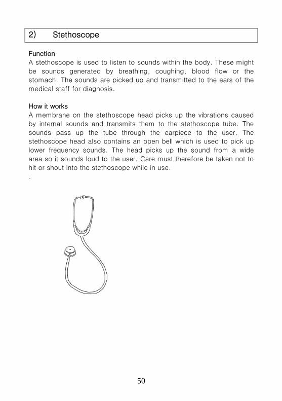
2) Stethoscope
Function
A stethoscope is used to listen to sounds within the body. These might
be sounds generated by breathing, coughing, blood flow or the
stomach. The sounds are picked up and transmitted to the ears of the
medical staff for diagnosis.
How it works
A membrane on the stethoscope head picks up the vibrations caused
by internal sounds and transmits them to the stethoscope tube. The
sounds pass up the tube through the earpiece to the user. The
stethoscope head also contains an open bell which is used to pick up
lower frequency sounds. The head picks up the sound from a wide
area so it sounds loud to the user. Care must therefore be taken not to
hit or shout into the stethoscope while in use.
.

51
Maintenance Checklist
Care and
Handling
• Check that the equipment is safely packed
• Remove any visible dirt
• Remove all dust and dirt with a damp cloth Remove
earpieces and clean the inside with warm water
Visual
checks
• Ensure all parts are present and are tightly fitted
• Remove or replace any cracked rubber parts
• Replace membrane if broken
Function
Checks
• Tap gently before use to check operation
• Check tube holder rotates easily within headpiece
• Check sound can be heard from both sides of
headpiece
Troubleshooting
Fault Possible causes Solution
1 Faint or NO
sound heard
Leakage or
blockage
Remove all parts and
check for leakage and
blockage.
2 Tube connector
does NOT stay in
headpiece
Broken locking
mechanism
Repair to be done by a
technician
3 Parts damaged
or faulty
Broken part Replace with part
taken from other units

52
3) Refrigerator (Electric and Solar)
Function
A refrigerator is a hospital plant that keeps health facility
vaccines, reagents and blood at a required environment (e.g.
temperature and humidity).
How it works
An electrical refrigerator can be a compression or absorption
type. Compression fridges use electrical power as a source of
power and it has four major components;
1- A compressor,
2- A condenser,
3- An Expansion valve/capillary tube,
4- An Evaporator
A compressor has a pump and electrical coil, both inside the
housing. The coil gets electrical power to form an electrical field
to drive the pump which then pumps the refrigerant in form of
gas with a high pressure to the condenser.
The condenser receives the refrigerant, removes heat and
condenses refrigerant into a liquid. The liquid refrigerant still at
high pressure goes to an expansion valve/capillary tube.
The Expansion valve or capillary tube
drops the refrigerant pressure and
temperature and this is where cooling
starts.
The Evaporator is the cooling part of the
refrigerator which evaporates the liquid
refrigerant back into gas form and
removes heat from the room.
53
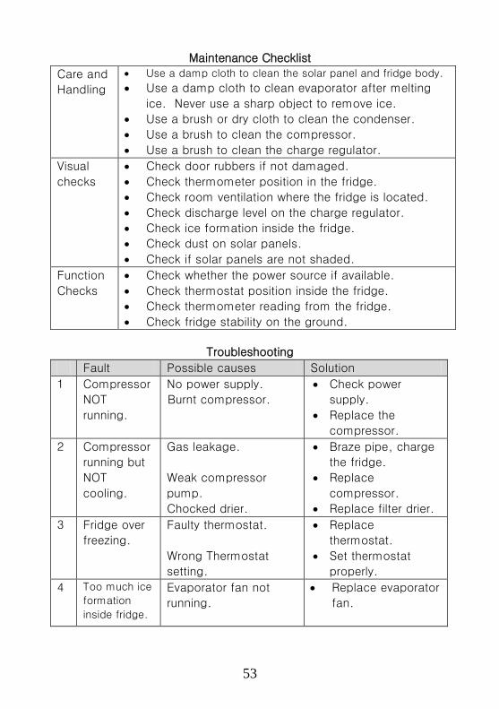
Maintenance Checklist
Care and
Handling
• Use a damp cloth to clean the solar panel and fridge body.
• Use a damp cloth to clean evaporator after melting
ice. Never use a sharp object to remove ice.
• Use a brush or dry cloth to clean the condenser.
• Use a brush to clean the compressor.
• Use a brush to clean the charge regulator.
Visual
checks
• Check door rubbers if not damaged.
• Check thermometer position in the fridge.
• Check room ventilation where the fridge is located.
• Check discharge level on the charge regulator.
• Check ice formation inside the fridge.
• Check dust on solar panels.
• Check if solar panels are not shaded.
Function
Checks
• Check whether the power source if available.
• Check thermostat position inside the fridge.
• Check thermometer reading from the fridge.
• Check fridge stability on the ground.
Troubleshooting
Fault Possible causes Solution
1
Compressor
NOT
running.
No power supply.
Burnt compressor.
• Check power
supply.
• Replace the
compressor.
2
Compressor
running but
NOT
cooling.
Gas leakage.
Weak compressor
pump.
Chocked drier.
• Braze pipe, charge
the fridge.
• Replace
compressor.
• Replace filter drier.
3
Fridge over
freezing.
Faulty thermostat.
Wrong Thermostat
setting.
• Replace
thermostat.
• Set thermostat
properly.
4
Too much ice
formation
inside fridge.
Evaporator fan not
running.
• Replace evaporator
fan.
54
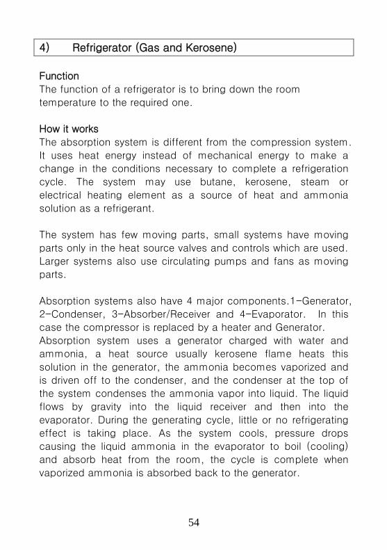
4) Refrigerator (Gas and Kerosene)
Function
The function of a refrigerator is to bring down the room
temperature to the required one.
How it works
The absorption system is different from the compression system.
It uses heat energy instead of mechanical energy to make a
change in the conditions necessary to complete a refrigeration
cycle. The system may use butane, kerosene, steam or
electrical heating element as a source of heat and ammonia
solution as a refrigerant.
The system has few moving parts, small systems have moving
parts only in the heat source valves and controls which are used.
Larger systems also use circulating pumps and fans as moving
parts.
Absorption systems also have 4 major components.1-Generator,
2-Condenser, 3-Absorber/Receiver and 4-Evaporator. In this
case the compressor is replaced by a heater and Generator.
Absorption system uses a generator charged with water and
ammonia, a heat source usually kerosene flame heats this
solution in the generator, the ammonia becomes vaporized and
is driven off to the condenser, and the condenser at the top of
the system condenses the ammonia vapor into liquid. The liquid
flows by gravity into the liquid receiver and then into the
evaporator. During the generating cycle, little or no refrigerating
effect is taking place. As the system cools, pressure drops
causing the liquid ammonia in the evaporator to boil (cooling)
and absorb heat from the room, the cycle is complete when
vaporized ammonia is absorbed back to the generator.
55
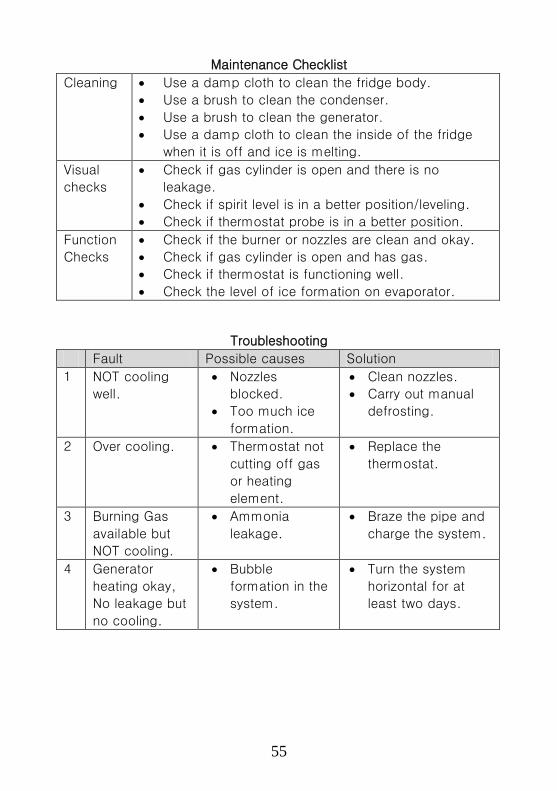
Maintenance Checklist
Cleaning • Use a damp cloth to clean the fridge body.
• Use a brush to clean the condenser.
• Use a brush to clean the generator.
• Use a damp cloth to clean the inside of the fridge
when it is off and ice is melting.
Visual
checks
• Check if gas cylinder is open and there is no
leakage.
• Check if spirit level is in a better position/leveling.
• Check if thermostat probe is in a better position.
Function
Checks
• Check if the burner or nozzles are clean and okay.
• Check if gas cylinder is open and has gas.
• Check if thermostat is functioning well.
• Check the level of ice formation on evaporator.
Troubleshooting
Fault Possible causes Solution
1
NOT cooling
well.
• Nozzles
blocked.
• Too much ice
formation.
• Clean nozzles.
• Carry out manual
defrosting.
2
Over cooling. • Thermostat not
cutting off gas
or heating
element.
• Replace the
thermostat.
3
Burning Gas
available but
NOT cooling.
• Ammonia
leakage.
• Braze the pipe and
charge the system.
4
Generator
heating okay,
No leakage but
no cooling.
• Bubble
formation in the
system.
• Turn the system
horizontal for at
least two days.

56
5) Weighing Scales
Function
Measuring patient weight is an important part of monitoring health as
well as calculating drug and radiation doses. It is therefore vital that
scales continue to operate accurately. They can be used for all ages of
patient and therefore vary in the range of weights that are measured.
They can be arranged for patients to stand on, or can be set up for
weighing wheelchair bound patients. For infants, the patient can be
suspended in a sling below the scale or placed in a weighing cot on
top of the scale.
How it works
Mechanical scales have a spring deflected by patient weight. The
spring pushes a pointer along a display or rotates a disc to indicate
weight. Electronic scales have a sensor (pressure sensor) that bends
under patient weight and the circuitry converts this to displayed digits.
This pressure sensor under strain induces an electric potential which is
directly proportional to the applied force (weight).

57
Maintenance Checklist
Care and
Handling
• Wipe off dust and replace dust cover after checks
• Clear away any dirt or hair on controls and feet
• Clean exterior with damp cloth and dry off
• Clean off then repaint any exposed or rusted metal
Visual
checks
• If bent, cracked or damaged, send for repair
• Tighten any loose screws and check parts are fitted
tightly
Function
Checks
• Check zero at start of day and before each patient
• Check reading is accurate using a known weight
• Send for repair if inaccurate or sticking
• Replace battery if display shows low battery
Troubleshooting
Fault Possible causes Solution
1 Zero point can
NOT be set
Scale is not level
Zero control broken
or internal part
jammed
Set scale on level
ground and Retest
Repair or change parts
2 Movement is
stiff or jerky
Dirt lodged inside
Internal blockage
Remove any visible dirt
or foreign body and
reset
Lubricate /repair
3 Reading is
inaccurate
Zero not properly
set
Calibration error
Reset to zero
Recalibrate
4 Electronic
display is blank
Battery / power
failed
Replace battery or
power supply and
retest

58
6) Suction Machines (Aspirators)
Function
Suction machines (also known as aspirators) are used to remove
unwanted fluid from body cavities. They are found in operating theatres,
delivery suites, ENT and emergency departments. Smaller specialized
suction machines are used in dental departments.
How it works
Suction is generated by a pump. This is normally an electrically
powered motor, but manually
powered versions are also often
found. The pump generates a
suction that draws air from a bottle.
The reduced pressure in this bottle
then draws the fluid from the
patient via a tube. The fluid
remains in the bottle until disposal
is possible. A valve prevents fluid
from passing into the motor itself.
Maintenance Checklist
Care and
Handling
• Wipe dust off exterior of the equipment and bottle cover.
• Wash bottle and patient tubing with sterilizing solution
• Wipe round bottle seal with damp cloth, replace if
cracked
• Remove dirt from wheels / moving parts
Visual
Checks
• Check if all fittings & accessories are mounted correctly
• Check if filter is clean
• Check if parts are fitted and replace any cracked tubes
• Check if mains cable has no bare wire and is not
damaged
Function
Checks
• Check that all switches and vacuum control operate
correctly
• Check for air and liquid leakage
59
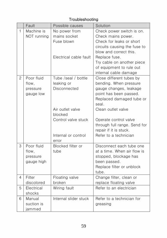
Troubleshooting
Fault Possible causes Solution
1 Machine is
NOT running
No power from
mains socket
Fuse blown
Electrical cable fault
Check power switch is on.
Check mains power.
Check for leaks or short
circuits causing the fuse to
blow and correct this.
Replace fuse.
Try cable on another piece
of equipment to rule out
internal cable damage
2 Poor fluid
flow,
pressure
gauge low
Tube /seal / bottle
leaking or
Disconnected
Air outlet valve
blocked
Control valve stuck
Internal or control
error
Close different tubes by
bending. When pressure
gauge changes, leakage
point has been passed.
Replaced damaged tube or
seal.
Clean outlet valve
Operate control valve
through full range. Send for
repair if it is stuck.
Refer to a technician
3 Poor fluid
flow,
pressure
gauge high
Blocked filter or
tube
Disconnect each tube one
at a time. When air flow is
stopped, blockage has
been passed.
Replace filter or unblock
tube.
4 Filter
discolored
Floating valve
broken
Change filter, clean or
replace floating valve
5 Electrical
shocks
Wiring fault Refer to an electrician
6 Manual
suction is
jammed
Internal slider stuck Refer to a technician for
greasing
60
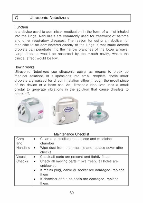
7) Ultrasonic Nebulizers
Function
Is a device used to administer medication in the form of a mist inhaled
into the lungs. Nebulizers are commonly used for treatment of asthma
and other respiratory diseases. The reason for using a nebulizer for
medicine to be administered directly to the lungs is that small aerosol
droplets can penetrate into the narrow branches of the lower airways.
Large droplets would be absorbed by the mouth cavity, where the
clinical effect would be low.
How it works
Ultrasonic Nebulizers use ultrasonic power as means to break up
medical solutions or suspensions into small droplets, these small
droplets are passed for direct inhalation either through the mouthpiece
of the device or a hose set. An Ultrasonic Nebulizer uses a small
crystal to generate vibrations in the solution that cause droplets to
break off.
Maintenance Checklist
Care
and
Handling
• Clean and sterilize mouthpiece and medicine
chamber
• Wipe dust from the machine and replace cover after
checks
Visual
Checks
• Check all parts are present and tightly fitted
• Check all moving parts move freely, all holes are
unblocked
• If mains plug, cable or socket are damaged, replace
them
• If chamber and tube seals are damaged, replace
them.

61
Function
Checks
• Check the whole system functions before use
• Before next use, check that there is adequate
nebulization.
• Check that the compressor fan is working without
excessive noise.
Troubleshooting
Fault Possible causes Solution
1 Equipment
is NOT
working
No power from
mains socket/
Blown mains fuse
Electrical cable
fault
Check power switch is on.
Replace fuse with correct
current ratings.
Check mains power.
Try cable on another piece of
equipment.
2 Equipment
is on but
flow is
absent
Filter is blocked
Pipe is twisted or
nebulizer
chamber/mouth
piece is blocked.
Clean filter
Connect pipe properly, clean
chamber / mouthpiece
3 Inadequate
nebulizing
amount
Output adjustment
not correctly set.
Mouth piece
cracked
Vibration generator
weak
Adjust output as directed in
the user manual
Replace mouthpiece
Replace vibration generator.
4 Electrical
shocks
Improper
earthing/grounding
of the machine.
Bare wires touching
the body of the
machine
Earth the machine
appropriately
Insulate all live conductors
62
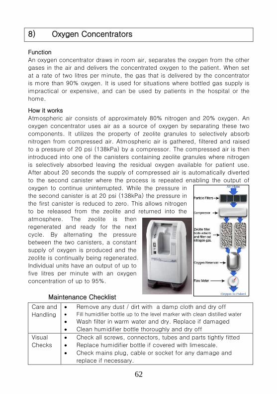
8) Oxygen Concentrators
Function
An oxygen concentrator draws in room air, separates the oxygen from the other
gases in the air and delivers the concentrated oxygen to the patient. When set
at a rate of two litres per minute, the gas that is delivered by the concentrator
is more than 90% oxygen. It is used for situations where bottled gas supply is
impractical or expensive, and can be used by patients in the hospital or the
home.
How it works
Atmospheric air consists of approximately 80% nitrogen and 20% oxygen. An
oxygen concentrator uses air as a source of oxygen by separating these two
components. It utilizes the property of zeolite granules to selectively absorb
nitrogen from compressed air. Atmospheric air is gathered, filtered and raised
to a pressure of 20 psi (138kPa) by a compressor. The compressed air is then
introduced into one of the canisters containing zeolite granules where nitrogen
is selectively absorbed leaving the residual oxygen available for patient use.
After about 20 seconds the supply of compressed air is automatically diverted
to the second canister where the process is repeated enabling the output of
oxygen to continue uninterrupted. While the pressure in
the second canister is at 20 psi (138kPa) the pressure in
the first canister is reduced to zero. This allows nitrogen
to be released from the zeolite and returned into the
atmosphere. The zeolite is then
regenerated and ready for the next
cycle. By alternating the pressure
between the two canisters, a constant
supply of oxygen is produced and the
zeolite is continually being regenerated.
Individual units have an output of up to
five litres per minute with an oxygen
concentration of up to 95%.
Maintenance Checklist
Care and
Handling
• Remove any dust / dirt with a damp cloth and dry off • Fill humidifier bottle up to the level marker with clean distilled water
• Wash filter in warm water and dry. Replace if damaged
• Clean humidifier bottle thoroughly and dry off
Visual
Checks
• Check all screws, connectors, tubes and parts tightly fitted
• Replace humidifier bottle if covered with limescale.
• Check mains plug, cable or socket for any damage and
replace if necessary.
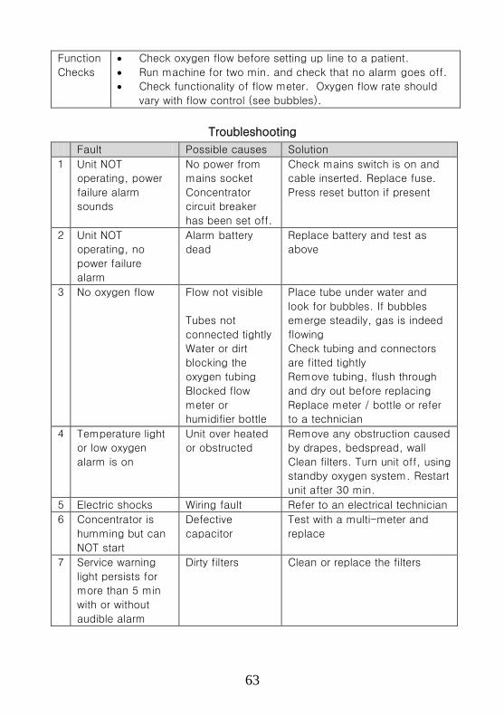
63
Function
Checks
• Check oxygen flow before setting up line to a patient.
• Run machine for two min. and check that no alarm goes off.
• Check functionality of flow meter. Oxygen flow rate should
vary with flow control (see bubbles).
Troubleshooting
Fault Possible causes Solution
1 Unit NOT
operating, power
failure alarm
sounds
No power from
mains socket
Concentrator
circuit breaker
has been set off.
Check mains switch is on and
cable inserted. Replace fuse.
Press reset button if present
2 Unit NOT
operating, no
power failure
alarm
Alarm battery
dead
Replace battery and test as
above
3 No oxygen flow Flow not visible
Tubes not
connected tightly
Water or dirt
blocking the
oxygen tubing
Blocked flow
meter or
humidifier bottle
Place tube under water and
look for bubbles. If bubbles
emerge steadily, gas is indeed
flowing
Check tubing and connectors
are fitted tightly
Remove tubing, flush through
and dry out before replacing
Replace meter / bottle or refer
to a technician
4 Temperature light
or low oxygen
alarm is on
Unit over heated
or obstructed
Remove any obstruction caused
by drapes, bedspread, wall
Clean filters. Turn unit off, using
standby oxygen system. Restart
unit after 30 min.
5 Electric shocks Wiring fault Refer to an electrical technician
6 Concentrator is
humming but can
NOT start
Defective
capacitor
Test with a multi-meter and
replace
7 Service warning
light persists for
more than 5 min
with or without
audible alarm
Dirty filters Clean or replace the filters

64
9) Oxygen Cylinders and Flow meters
Function
Medical gases such as oxygen, nitrous oxide etc. are intended for
administration to a patient in anaesthesia, therapy or diagnosis. An
oxygen cylinder is a cylindrically shaped metal container used to store
oxygen that has been compressed to a very high pressure. Oxygen
cylinders, which come in different sizes, are usually coloured black with
a white top; in some cases, it may be a small cylinder that is entirely
black. The black colour helps to differentiate it from other gases that
are stored in similar containers. Cylinders are fitted with customized
valves (either bull nose or pin index type) with valve guards, which are
opened with valve keys.
A flow meter is an instrument used to measure
the flow rate of a liquid or a gas. In healthcare
facilities, gas flow meters are used to deliver
oxygen at a controlled rate either directly to
patients or through medical devices.
Oxygen flow meters are used on
oxygen tanks and oxygen
concentrators to measure the
amount of oxygen reaching the
patient or user. Sometimes bottles
are fitted to humidify the oxygen by
bubbling it through water.
Maintenance Checklist
Care and
Handling
• Ensure delivery tubes and masks are sterile
• If humidifier bottle is used, refill with clean water
• Clean cylinder, valve and flow meter with a damp
cloth
Visual
Checks
• Check that the cylinder is the correct type and marked
oxygen.
• Check all parts are fitted tightly and correctly
• Check for leakage: hissing sound or reduction in
pressure

65
Function
Checks
• Before use, ensure cylinder is filled & flow is present
• Close cylinder valve after each use.
• Remove valve dust with brief, fast oxygen flow
• Check flow can be varied using flow control
Troubleshooting
Fault Possible causes Solution
1 No oxygen is
flowing
Cylinder is empty
Flow meter knob
or cylinder valve
is closed.
Faulty regulator
Replace cylinder
Open valves, then check
flow meter registers flow
Close all valves and
replace regulator
2 Leakage from
cylinder or
Flow meter
Cylinder is not
connected to
regulator properly
Faulty or missing
washer
Flow meter seal
damaged or
loose
Cylinder faulty
Tighten all fittings
Replace washer
Tighten flow meter
Label “Faulty” and return
to manufacturer
3 Leakage can
NOT be located
Leakage too
small to be heard
Apply detergent solution
(NOT oily soap) to joints.
Bubbles will show at leak
point. Clean/replace
washer and tighten at that
joint.
4 Flow meter ball
NOT moving,
yet oxygen is
flowing
Faulty flow meter Close all valves,
disconnect flow meter and
clean inside. Reconnect
and test.
5 Pressure gauge
does NOT
show pressure,
yet oxygen is
flowing
Faulty pressure
gauge
Refer to biomedical
technician for
Replacement

66
10) Electronic Diagnostic Equipment (General)
Function
There are many pieces of equipment in a hospital that use electronics
for operation. The maintenance of such equipment is a task for
specialized and trained staff. However, regular inspection and cleaning
will help such equipment last for a long time and operate safely. These
are tasks that the equipment user can carry out and should be done
regularly, as laid out on the checklists.
The type of equipment that is included in this category are for instance
audiometers, blood gas analyzers, cardiac monitors, cryoprobes,
infusion pumps and stimulators. The steps in this section can also be
applied to most laboratory equipment.
How it works
The electrical part of the machine is the most important for safety, and
also is the most likely to have problems relating to power supply. The
power supply converts the voltage to a lower stable value to make the
equipment work and also protects the patient from the mains voltage.
Any damage to the power supply, or any liquid spilled into the
equipment could result in very serious consequences. The maintenance
checklist therefore majors on checking the cables, fuses and power
connectors. If a device uses low voltage batteries, it is safer to use. In
this case, the user should take care that the batteries are removed if
the equipment will not be used for longer than one month, as chemical
spillage can occur. Rechargeable batteries must be kept topped up
with charge.
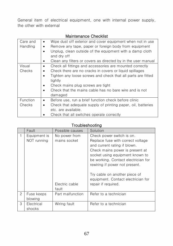
67
General item of electrical equipment, one with internal power supply,
the other with external
Maintenance Checklist Care and
Handling
• Wipe dust off exterior and cover equipment when not in use
• Remove any tape, paper or foreign body from equipment
• Unplug, clean outside of the equipment with a damp cloth
and dry off
• Clean any filters or covers as directed by in the user manual
Visual
Checks
• Check all fittings and accessories are mounted correctly
• Check there are no cracks in covers or liquid spillages
• Tighten any loose screws and check that all parts are fitted
tightly
• Check mains plug screws are tight
• Check that the mains cable has no bare wire and is not
damaged
Function
Checks
• Before use, run a brief function check before clinic
• Check that adequate supply of printing paper, oil, batteries
etc. are available.
• Check that all switches operate correctly
Troubleshooting Fault Possible causes Solution
1 Equipment is
NOT running
No power from
mains socket
Electric cable
fault
Check power switch is on.
Replace fuse with correct voltage
and current rating if blown.
Check mains power is present at
socket using equipment known to
be working. Contact electrician for
rewiring if power not present.
Try cable on another piece of
equipment. Contact electrician for
repair if required.
2 Fuse keeps
blowing
Part malfunction Refer to a technician
3 Electrical
shocks
Wiring fault Refer to a technician

68
11) General X-Ray Machine
Function
X-Ray machines are used for imaging bones and
hard tissues and diagnosing fractures, joint
defects, choked lungs etc. Sometimes contrast
agents are also used to highlight any defects in
the abdomen under X-rays.
How it works
X-rays are high energy electromagnetic waves. The transformer
produces a high voltage that directs electrons onto a target in the
machine head. X-rays are produced by the target and are directed into
beams by a collimator towards the human body. Soft body tissue
absorbs less X-rays, i.e., more radiation goes through, whereas bone
and other solids prevent most of the X-rays from going through. A
photographic film or electronic sensor displays how much X ray has
passed through, forming an image of the interior of the body. Bone
appears nearly white, because few X-rays strike the corresponding part
of the film, leaving it largely unexposed; soft tissue allows much more
radiation to pass through, darkening the film in those places.
Users must ensure proper radiation safety protocols and supervision is
in place.
(Control panel and transformer not shown)

69
Maintenance Checklist
Care and
Handling
• Remove any items or foreign body from equipment
• Clean all dust and dirt from the X-Ray machine and room
Visual
Checks
• Check that all parts are present and connected
• Check that cables are not twisted and remove from service
if any damage is visible
• If any plug, cable or socket is damaged, refer to distributor
• Check lead aprons for any defects
• Check table, cassette holder & grids for smooth movement
Function
Checks
• Switch on power and check all indicators function
• If machine has not been in use, wear lead apron and check
whether exposure indicator lights on switch operates
• Check collimator bulb, replace with correct type if needed
• Check power supply voltage, and regulation
• Check protection earthing for the Equipment
• Check that internal earth connections are firm
Troubleshooting
Fault Possible causes Solution
1 X-Ray unit
does NOT
switch on
Mains power not
connected
Check the machine is plugged into
the mains socket and that all
switches are on. Replace fuse.
Check if mains power is present at
socket using equipment known to
be working. Rewiring by electrician.
2 X-Ray
machine NOT
exposing,
even when
power is on.
Safety interlock is
on
Exposure switch
cable problem
Internal error
Check safety locks, all switches
Check for any loose connection
Refer to distributor’s technician
3 Poor X-Ray
image quality
X-Ray tube
problem
Refer to distributor’s technician
4 The table
does NOT
move.
Table motor or
cable problem.
Safety switch or
fuse problem
Control circuit
problem
Check all cable connections
Check relevant fuse or switch
Refer to biomedical technician
5 Electrical
shocks
Wiring fault Refer to distributor’s technician
immediately

70
12) Ultrasound Scanner
Function
Diagnostic ultrasound machines are used to give images of structures
within the body. Other kinds of machines (e.g. therapeutic and
lithotripsy) are not dealt with herein. The diagnostic machine probes,
which produce the ultrasound, come in a variety of sizes and styles,
each type being produced for a particular special use. Some require a
large trolley for all the parts of the unit, while the smallest come in a
small box with only an audio loudspeaker for output. They may be
found in cardiology, maternity, outpatients and radiology departments
and will often have a printer attached for recording images. Unlike X-
rays, ultrasound poses no danger to the human body.
How it works
The ultrasound probe contains a crystal that sends out bursts of high
frequency vibrations that pass through gel and then through the body.
Soft tissue and bone reflect echoes back to the probe, while pockets
of liquid pass the ultrasound straight through.
The echoes are picked up and arranged into
an image displayed on a screen. The machine
offers a number of
processing options for
the signal and image
and also allows the
user to measure
physical features
displayed on the
screen. This requires
the machine to
incorporate a computer.
Maintenance Checklist
Care
and
Handling
• Wipe dust off exterior and cover equipment after use
• Remove any items or foreign body from equipment
• Wipe probe with alcohol-free tissue or cloth
• Remove, clean and dry external filter if present

71
Visual
Checks
• Check that all fittings and accessories are mounted
correctly
• Check that cables are not twisted and probe is safely
stored
• Check that mains plug screws are tight
• Check that mains cable has no bare wire and is not
damaged
Function
Checks
• If machine has not been in use, run and test briefly
Troubleshooting
Fault Possible causes Solution
1 Equipment
is NOT
running
No power from
mains socket
Electrical cable
fault
Check power switch is on.
Replace fuse. Check mains
power is working.
Repair or exchange the
cable. Try cable on another
piece of equipment.
2 Fuse keeps
blowing
Power supply or
cable fault
Refer to distributor’s
technician
3 Probe head
damaged or
noisy
Possible internal
fault
Exchange probe.
4 Image
quality poor
Gel insufficient
Controls set
incorrectly
Mains voltage is
too low
Use more ultrasound gel
Check controls for correct
positioning and operation
(refer to user manual)
Use voltage stabilizer
5 Display /
computer
error
Software fault Turn machine off and restart.
If problem persists, refer to
distributor’s technician
6 Electrical
shocks
Wring problem Rewiring/repair by a
technician
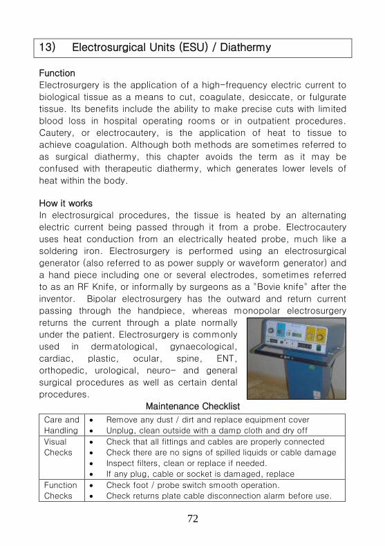
72
13) Electrosurgical Units (ESU) / Diathermy
Function
Electrosurgery is the application of a high-frequency electric current to
biological tissue as a means to cut, coagulate, desiccate, or fulgurate
tissue. Its benefits include the ability to make precise cuts with limited
blood loss in hospital operating rooms or in outpatient procedures.
Cautery, or electrocautery, is the application of heat to tissue to
achieve coagulation. Although both methods are sometimes referred to
as surgical diathermy, this chapter avoids the term as it may be
confused with therapeutic diathermy, which generates lower levels of
heat within the body.
How it works
In electrosurgical procedures, the tissue is heated by an alternating
electric current being passed through it from a probe. Electrocautery
uses heat conduction from an electrically heated probe, much like a
soldering iron. Electrosurgery is performed using an electrosurgical
generator (also referred to as power supply or waveform generator) and
a hand piece including one or several electrodes, sometimes referred
to as an RF Knife, or informally by surgeons as a "Bovie knife" after the
inventor. Bipolar electrosurgery has the outward and return current
passing through the handpiece, whereas monopolar electrosurgery
returns the current through a plate normally
under the patient. Electrosurgery is commonly
used in dermatological, gynaecological,
cardiac, plastic, ocular, spine, ENT,
orthopedic, urological, neuro- and general
surgical procedures as well as certain dental
procedures.
Maintenance Checklist
Care and
Handling
• Remove any dust / dirt and replace equipment cover
• Unplug, clean outside with a damp cloth and dry off
Visual
Checks
• Check that all fittings and cables are properly connected
• Check there are no signs of spilled liquids or cable damage
• Inspect filters, clean or replace if needed.
• If any plug, cable or socket is damaged, replace
Function
Checks
• Check foot / probe switch smooth operation.
• Check returns plate cable disconnection alarm before use.
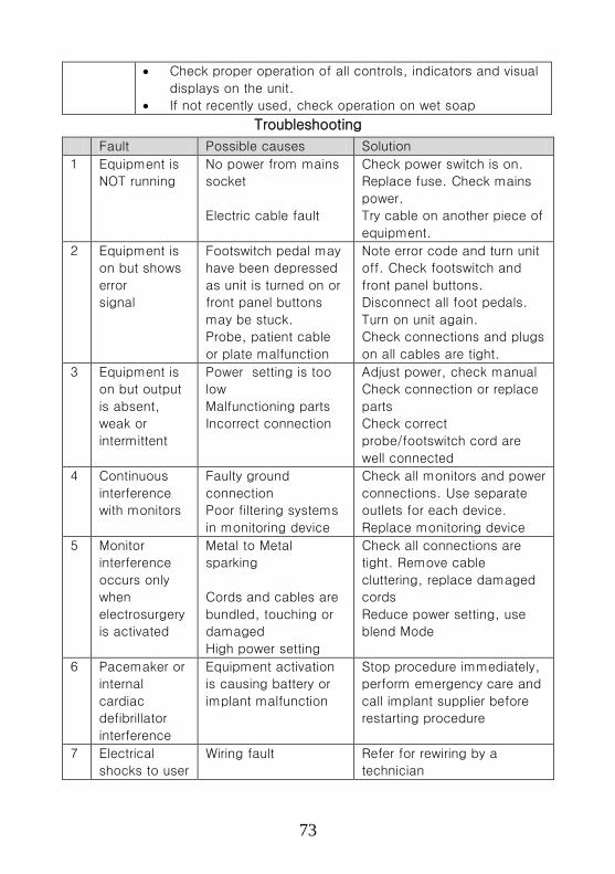
73
• Check proper operation of all controls, indicators and visual
displays on the unit.
• If not recently used, check operation on wet soap
Troubleshooting
Fault Possible causes Solution
1 Equipment is
NOT running
No power from mains
socket
Electric cable fault
Check power switch is on.
Replace fuse. Check mains
power.
Try cable on another piece of
equipment.
2 Equipment is
on but shows
error
signal
Footswitch pedal may
have been depressed
as unit is turned on or
front panel buttons
may be stuck.
Probe, patient cable
or plate malfunction
Note error code and turn unit
off. Check footswitch and
front panel buttons.
Disconnect all foot pedals.
Turn on unit again.
Check connections and plugs
on all cables are tight.
3 Equipment is
on but output
is absent,
weak or
intermittent
Power setting is too
low
Malfunctioning parts
Incorrect connection
Adjust power, check manual
Check connection or replace
parts
Check correct
probe/footswitch cord are
well connected
4 Continuous
interference
with monitors
Faulty ground
connection
Poor filtering systems
in monitoring device
Check all monitors and power
connections. Use separate
outlets for each device.
Replace monitoring device
5 Monitor
interference
occurs only
when
electrosurgery
is activated
Metal to Metal
sparking
Cords and cables are
bundled, touching or
damaged
High power setting
Check all connections are
tight. Remove cable
cluttering, replace damaged
cords
Reduce power setting, use
blend Mode
6 Pacemaker or
internal
cardiac
defibrillator
interference
Equipment activation
is causing battery or
implant malfunction
Stop procedure immediately,
perform emergency care and
call implant supplier before
restarting procedure
7 Electrical
shocks to user
Wiring fault Refer for rewiring by a
technician
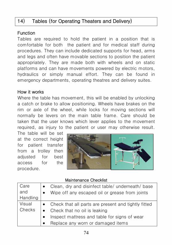
74
14) Tables (for Operating Theaters and Delivery)
Function
Tables are required to hold the patient in a position that is
comfortable for both the patient and for medical staff during
procedures. They can include dedicated supports for head, arms
and legs and often have movable sections to position the patient
appropriately. They are made both with wheels and on static
platforms and can have movements powered by electric motors,
hydraulics or simply manual effort. They can be found in
emergency departments, operating theatres and delivery suites.
How it works
Where the table has movement, this will be enabled by unlocking
a catch or brake to allow positioning. Wheels have brakes on the
rim or axle of the wheel, while locks for moving sections will
normally be levers on the main table frame. Care should be
taken that the user knows which lever applies to the movement
required, as injury to the patient or user may otherwise result.
The table will be set
at the correct height
for patient transfer
from a trolley then
adjusted for best
access for the
procedure.
Maintenance Checklist
Care
and
Handling
• Clean, dry and disinfect table/ underneath/ base
• Wipe off any escaped oil or grease from joints
Visual
Checks • Check that all parts are present and tightly fitted
• Check that no oil is leaking
• Inspect mattress and table for signs of wear
• Replace any worn or damaged items

75
Function
Checks • Check essential movements before use
• Check wheel brakes function and wheels rotate
• Ensure all moving parts can move, applying
grease if needed
Troubleshooting
Fault Possible causes Solution
1 Table can NOT
be relocated Wheels jammed
Electric motor not
operational (electrically driven
table)
Clean wheels, remove
obstruction
Check power to table Replace fuse if blown If problem persists,
refer to technician
2 Table section
or body can
NOT be moved
Lock or lever is
jammed
No power to
electric table
No oil in hydraulic
table
Clean jammed part,
remove rust and dirt,
lightly oil and replace Check correct switch
is used Check power and
fuses
Refill hydraulic oil if
needed Check no leakage
occurs 3 Oil leakage
from hydraulic
table
Oil leakage Worn out gasket
oil seals.
Locate leak and block
it. Clear spillage. Refer to technician.
4 Electric shocks Wiring fault Refer to technician
immediately
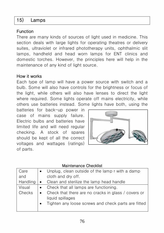
76
15) Lamps
Function
There are many kinds of sources of light used in medicine. This
section deals with large lights for operating theatres or delivery
suites, ultraviolet or infrared phototherapy units, ophthalmic slit
lamps, handheld and head worn lamps for ENT clinics and
domestic torches. However, the principles here will help in the
maintenance of any kind of light source.
How it works
Each type of lamp will have a power source with switch and a
bulb. Some will also have controls for the brightness or focus of
the light, while others will also have lenses to direct the light
where required. Some lights operate off mains electricity, while
others use batteries instead. Some lights have both, using the
batteries for back-up power in
case of mains supply failure.
Electric bulbs and batteries have
limited life and will need regular
checking. A stock of spares
should be kept of all the correct
voltages and wattages (ratings)
of parts.
Maintenance Checklist
Care
and
Handling
• Unplug, clean outside of the lamp r with a damp
cloth and dry off.
• Clean and sterilize the lamp head handle
Visual
Checks
• Check that all lamps are functioning.
• Check that there are no cracks in glass / covers or
liquid spillages
• Tighten any loose screws and check parts are fitted
77
Function
Checks
• Check that switches and focus knob operate
correctly
• Check working condition of moving parts
Troubleshooting
Fault Possible causes Solution
1 No light or
power on
visible
No power at
mains socket
Dead battery
Blown bulb
Battery leakage
Electrical cable
fault
Internal wiring
fault
Check power switch is on.
Replace fuse. Check mains
power.
Charge or replace battery
Replace bulb with correct
voltage and wattage
Remove batteries, clean
battery terminals and replace
with new battery
Try cable on another piece of
equipment.
Refer to an Electrician
2 Fuse /
bulb
keeps
blowing
Fuse or bulb is
wrong rating
Power supply or
cable fault
Replace with correct rating
Refer to an electrician
3 Light can
NOT be
made
bright
enough
Dirt on lens or
tube
Poor power
supply
Wrong bulb rating
Control
malfunction
Clean area with dry, clean
cotton
Check power line or replace
Batteries
Check bulb rating is correct
Refer to an electrician
4 Electrical
shocks
Wiring fault Refer to an electrician

78
16) Anesthesia Machine
Function
The anesthesia machine is used to support the administration of
anaesthesia. The most common type of anesthesia machine is the
continuous-flow type, which is designed to provide an accurate and
continuous supply of medical gases (such as oxygen and nitrous oxide),
mixed with an accurate concentration of unaesthetic vapour (such as
halothane or isoflurane), and deliver this to the patient at a safe
pressure and flow. Modern machines incorporate ventilator, suction unit
and patient monitoring devices.
How it works
Oxygen (O2), nitrous oxide (N2O) and sometimes air sources are
connected to the machine. Through gas flowmeters (or rotameters), a
controlled mixture of these gases along with anaesthetic vapour passes
through a vaporizer and is delivered to the patient. Sometimes a
ventilator is also connected with the machine for rebreathing thus
making it a closed circuit. With ventilators or a re-breathing patient
circuit, soda lime canisters are used to absorb the exhaled carbon
dioxide and fresh gases are added to the circuit for reuse. Pressure
gauges are installed on the anaesthesia machine to monitor gas
pressure. Generally, 25% (or 21%) oxygen is always kept in the circuit
(delivered to patient) as a safety feature. The device which ensures this
minimum oxygen in the circuit is called a hypoxic guard. Some basic
machines do not
have this feature,
but have a nitrous
lock which stops
the delivery of N2O
in absence of O2
pressure.
Machines give
various alarms to
alert operators.
79
Maintenance Checklist Care and
Handling
• Remove water and waste matter from inside
• Clean inside and outside with a damp cloth and dry off
Audio-
Visual
checks
• If any leak is audible, check with soapy solution
• Check all seals, connectors, adapters and parts are tight
• Check all moving parts move freely, all holes are unblocked
• Check connections for leakage with soap solution & dry off
• Check all fittings for proper assembly
• Replace soda lime if it has turned blue
• Replace any deteriorated hoses and tubing
• If seal, plug, cable or socket are damaged, replace
Function
Checks
• After use, depressurize system and replace all caps / covers
• Before use, check pressure gauges rise and there are no
leaks
Troubleshooting
Fault Possible causes Solution
1 Equipment
NOT
running
No power at mains
socket
Electric cable fault
Check power switch is on.
Replace fuse. Check mains
power is present at socket using
equipment known to be working.
Rewiring if power not present.
2 No Gas
output
No O2 pressure in
cylinder / gas supply
Check pressure gauges
(4 bar or 4 kg/cm2)
Restore gas supply or replace
gas cylinders
Replace O2 cylinder and/or N2O
cylinder in case of low pressure.
3 O2 failure
alarm
NOT
working
Alarm battery is low.
Alarm device is not
working
Check alarm setting range,
alarm on/off, alarm lamp blow
out
4 Machine
has leaks
Poor seal(commonly
occurring around tubing
connections, flow
valves and O2/N2O
yokes)Cylinders not
seated properly
Clean leaking seal or gasket,
replace if broken.
Refit cylinders in yokes and
retest. If leaks remain, repair by
technician.
5 Flow
meter
fault
Over tightening of the
needle valve or sticking
of the float / ball
Repair by technician or
outsourcing service
6 Electrical
shocks
Wiring fault Rewiring/repair by electrician
immediately
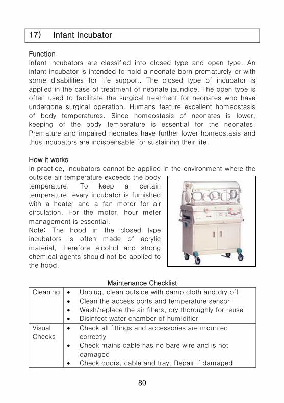
80
17) Infant Incubator
Function
Infant incubators are classified into closed type and open type. An
infant incubator is intended to hold a neonate born prematurely or with
some disabilities for life support. The closed type of incubator is
applied in the case of treatment of neonate jaundice. The open type is
often used to facilitate the surgical treatment for neonates who have
undergone surgical operation. Humans feature excellent homeostasis
of body temperatures. Since homeostasis of neonates is lower,
keeping of the body temperature is essential for the neonates.
Premature and impaired neonates have further lower homeostasis and
thus incubators are indispensable for sustaining their life.
How it works
In practice, incubators cannot be applied in the environment where the
outside air temperature exceeds the body
temperature. To keep a certain
temperature, every incubator is furnished
with a heater and a fan motor for air
circulation. For the motor, hour meter
management is essential.
Note: The hood in the closed type
incubators is often made of acrylic
material, therefore alcohol and strong
chemical agents should not be applied to
the hood.
Maintenance Checklist
Cleaning • Unplug, clean outside with damp cloth and dry off
• Clean the access ports and temperature sensor
• Wash/replace the air filters, dry thoroughly for reuse
• Disinfect water chamber of humidifier
Visual
Checks
• Check all fittings and accessories are mounted
correctly
• Check mains cable has no bare wire and is not
damaged
• Check doors, cable and tray. Repair if damaged

81
Function
Checks
• Drain off the water tray. Run machine for 30 minutes
to dry the tray. Refill tray with sterile water before use.
• Check all controls operate correctly
• Check the readings of thermometer and oxygen
sensors change when breathed upon
• Check that batteries are working properly.
Troubleshooting
Fault Possible causes Solution
1 Incubator is
NOT running
No power from
mains
socket
Electrical cable
fault
Check power switch is on.
Replace fuse.
Check mains power.
Try cable on another piece
of equipment. Repair by
electrician, if required.
2 Fuse keeps
blowing
Power supply or
cable fault
Check the Manual and
troubleshoot properly
3 Alarms NOT
working
Alarm battery
dead.
Alarm off setting
Replace the battery and
recheck.
Check alarm setting.
4 Temperature
NOT
properly
controlled
Temperature
probe and sensor
not working
Incubator placed
indirect sunlight or
near a fan.
Fan or air duct
problem
Check the temperature
probes and sensor
connections. Replace the
temperature probe or
sensor, if required.
Move incubator if placed
near heat or draught
Unblock air duct if
obstructed.
5 Incubator
NOT heating
even when
the heater
lamp is on.
Heating element
problem
If accessible, replace
heating element.

82
18) Infant Warmer
Function
An infant warmer system provides a controlled source of radiant
heat for infants and pediatric patients.
How it works
The heater assembly consists of a radiant
heater controlled by electronic circuits. A
probe is used to monitor the patient’s skin
temperature. The patient’s skin temperature
is continuously displayed. Alarms activate to
alert the operator of a low or high patient
temperature, a skin temperature probe failure,
a power failure, equipment failure or a check
patient prompt.
Maintenance Checklist
Care and
Handling
• Clean the warmer at least once a week or after each
patient.
• The mattress, X-ray tray, bed and side panels may be
cleaned without immersing by using a disinfecting
agent safe for use on the materials.
Visual
Checks
• For units with casters, check that all casters are in
firm contact with the floor and that the warmer is
stable and moves freely.
• Examine the unit for objects placed on top of the
heater assembly.
Function
Checks
• Check that all accessories are mounted securely and
that the load limits are not exceeded.
• Connect the warmer to power source and verify the
operation of the control panel.
• Check operation of phototherapy warning light.
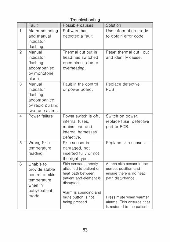
83
Troubleshooting
Fault Possible causes Solution
1
Alarm sounding
and manual
indicator
flashing.
Software has
detected a fault
Use information mode
to obtain error code.
2 Manual
indicator
flashing
accompanied
by monotone
alarm.
Thermal cut out in
head has switched
open circuit due to
overheating.
Reset thermal cut- out
and identify cause.
3 Manual
indicator
flashing
accompanied
by rapid pulsing
two tone alarm.
Fault in the control
or power board.
Replace defective
PCB.
4
Power failure Power switch is off,
internal fuses,
mains lead and
internal harnesses
defective.
Switch on power,
replace fuse, defective
part or PCB.
5
Wrong Skin
temperature
reading
Skin sensor is
damaged, not
inserted fully or not
the right type.
Replace skin sensor.
6
Unable to
provide stable
control of skin
temperature
when in
baby/patient
mode
Skin sensor is poorly
attached to patient or
heat path between
patient and element is
disrupted.
Alarm is sounding and
mute button is not
being pressed.
Attach skin sensor in the
correct position and
ensure there is no heat
path disturbance.
Press mute when warmer
alarms. This ensures heat
is restored to the patient.

84
19) Autoclaves
Function Sterilization is the killing of micro-organisms that could harm
patients. It can be done by flame or (steam, air, flame or boiling) or
by chemical means. Autoclaves use high pressure steam and
Sterilizers use boiling water mixed with chemicals to achieve this.
Materials are placed inside the unit for a carefully specified length
of time. Autoclaves achieve better sterilization than boiling water
sterilizers.
Heat is delivered to water either by electricity or flame. This
generates high temperature within the chamber. The autoclave also
contains high pressure when in use, hence the need for pressure
control valves and safety valves. Users must be careful to check
how long items need to be kept at the temperature reached.
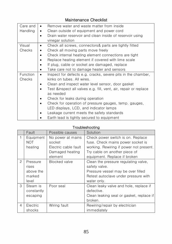
85
Maintenance Checklist
Care and
Handling
• Remove water and waste matter from inside
• Clean outside of equipment and power cord
• Drain water reservoir and clean inside of reservoir using
vinegar solution
Visual
Checks
• Check all screws, connectors& parts are tightly fitted
• Check all moving parts move freely
• Check internal heating element connections are tight
• Replace heating element if covered with lime scale
• If plug, cable or socket are damaged, replace
• Take care not to damage heater and sensors
Function
Checks
• Inspect for defects e.g. cracks, severe pits in the chamber,
kinks on tubes. All wires.
• Clean and inspect water level sensor, door gasket
• Test &inspect all valves e.g. fill, vent, air, repair or replace
as needed
• Check for leaks during operation
• Check for operation of pressure gauges, temp. gauges,
LED displays, LCD, and indicator lamps
• Leakage current meets the safety standards
• Earth lead is tightly secured to equipment
Troubleshooting
Fault Possible causes Solution
1 Equipment
NOT
heating
No power at mains
socket
Electric cable fault
Damaged heating
element
Check power switch is on. Replace
fuse. Check mains power socket is
working. Rewiring if power not present.
Try cable on another piece of
equipment. Replace if broken
2 Pressure
rises
above the
marked
level
Blocked valve Clean the pressure regulating valve,
safety valve.
Pressure vessel may be over filled
Retest autoclave under pressure with
water only.
3 Steam is
constantly
escaping
Poor seal
Clean leaky valve and hole, replace if
defective.
Clean leaking seal or gasket, replace if
broken.
4 Electric
shocks
Wiring fault Rewiring/repair by electrician
immediately
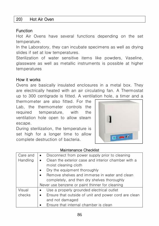
86
20) Hot Air Oven
Function
Hot Air Ovens have several functions depending on the set
temperature.
In the Laboratory, they can incubate specimens as well as drying
slides if set at low temperatures.
Sterilization of water sensitive items like powders, Vaseline,
glassware as well as metallic instruments is possible at higher
temperatures
How it works
Ovens are basically insulated enclosures in a metal box. They
are electrically heated with an air circulating fan. A Thermostat
up to 300 centigrade is fitted. A ventilation hole, a timer and a
thermometer are also fitted. For the
Lab, the thermometer controls the
required temperature, with the
ventilation hole open to allow steam
escape.
During sterilization, the temperature is
set high for a longer time to allow
complete destruction of bacteria.
Maintenance Checklist
Care and
Handling
• Disconnect from power supply prior to cleaning
• Clean the exterior case and interior chamber with a
moist cleaning cloth
• Dry the equipment thoroughly
• Remove shelves and immerse in water and clean
completely, and then dry shelves thoroughly
Never use benzene or paint thinner for cleaning
Visual
checks
• Use a properly grounded electrical outlet
• Ensure that outside of unit and power cord are clean
and not damaged
• Ensure that internal chamber is clean

87
• Ensure that the Heater element, air inlets, vent
outlets, control enclosures, door latches and hinges
are clean
Function
Checks
• Check that Temperature control sensor is not
damaged
• Check that circuit breakers & switches are
operational
• Check predetermined setting and temperatures
• Significantly higher temperature could indicate
temperature controller is failing
Troubleshooting
Fault Possible causes Solution
1
Erratic
temperature
Defective circuit board
Dirty sensor
Repair or replace new
one
Clean the sensor
2
Can NOT
heat
Defective circuit board
Burnout heater
Defective triac
Air leakage
Replace new one
Replace heater
Replace triac
Lock door completely
or replace door gasket
3
Can NOT
power up
Disconnected linkage
Mal-functional switch
Burnout heater
Blew fuse
Connect linkage
completely
Replace switch
Replace heater
Replace fuse
4
Failure set
temperature
Defective circuit board Repair or replace new
one
5 Unacceptable
uniformity
Defective fan Repair or replace fan
or adjust the air vents
6 Temperature
fluctuated
Dirty sensor,
Burnout electronic
parts
Defective circuit board
Clean sensor
Repair or replace parts
Repair or replace
circuit board
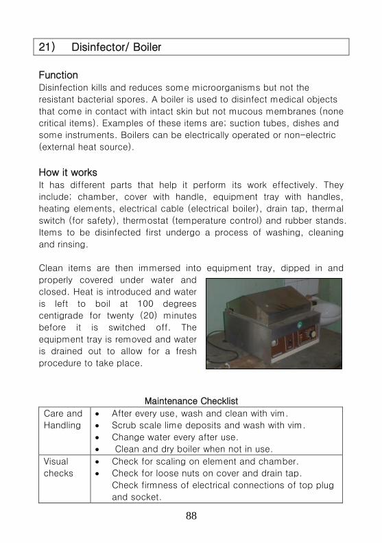
88
21) Disinfector/ Boiler
Function Disinfection kills and reduces some microorganisms but not the
resistant bacterial spores. A boiler is used to disinfect medical objects
that come in contact with intact skin but not mucous membranes (none
critical items). Examples of these items are; suction tubes, dishes and
some instruments. Boilers can be electrically operated or non-electric
(external heat source).
How it works It has different parts that help it perform its work effectively. They
include; chamber, cover with handle, equipment tray with handles,
heating elements, electrical cable (electrical boiler), drain tap, thermal
switch (for safety), thermostat (temperature control) and rubber stands.
Items to be disinfected first undergo a process of washing, cleaning
and rinsing.
Clean items are then immersed into equipment tray, dipped in and
properly covered under water and
closed. Heat is introduced and water
is left to boil at 100 degrees
centigrade for twenty (20) minutes
before it is switched off. The
equipment tray is removed and water
is drained out to allow for a fresh
procedure to take place.
Maintenance Checklist
Care and
Handling
• After every use, wash and clean with vim.
• Scrub scale lime deposits and wash with vim.
• Change water every after use.
• Clean and dry boiler when not in use.
Visual
checks
• Check for scaling on element and chamber.
• Check for loose nuts on cover and drain tap.
Check firmness of electrical connections of top plug
and socket.

89
Function
Checks
• Use trouble shooting guide (step by step approach).
• Ensure thermostat operates and element heats.
• Ensure switches are functional.
• Check functionality before next use.
Troubleshooting
Fault Possible causes Solution
1
Equipment
NOT heating
No power at mains
socket.
Fault on electric cable.
Heating element
blown.
Thermal safety switch
tripped.
Replace fuse.
Replace power cable.
Replace heating
element.
Reset circuit breaker,
switch on mains.
Reset safety switch.
2
Water takes
long to boil
One element faulty (for
more than one
element).
Scale deposits on the
element.
Thermostat wrongly
set.
Check one of the
elements, replace.
Remove scale
deposits.
Adjust thermostat
setting.
3
Heating
elements
keep blowing
frequently.
Much scale deposits.
Little water in the
chamber.
Faulty safety switch.
Faulty thermostat
De-scale heating
element.
Always put enough
water/user train.
Replace safety switch.
Replace thermostat.
4
Much steam
escapes.
Lid/cover does not
close well.
Drain valve does not
close well.
Many items in the
boiler chamber
Tighten loose nuts and
replace missing ones.
Replace drain valve.
Reduce on the items/
train user.

90
22) ECG (Electrocardiogram) Machine
ECG machines are used to monitor the electrical activity of the heart
and display it on a small screen or record it on a piece of paper. The
recordings are used to diagnose the condition of the heart muscle and
its nerve system.
The electrical activity is picked up by means of electrodes placed on
the skin. The signal is amplified, processed if necessary and then ECG
tracings displayed and printed. Some ECG machines also provide
preliminary interpretation of ECG recordings. There are 12 different
types of recording displayed depending upon the points from where the
recordings are taken
Care must be taken to make the electrode sites clean of dirt before
applying electrode jelly. Most problems occur with the patient cables or
electrodes.
Maintenance Checklist
Care and
Handling
• Clean the Printing head
• Clean body of equipment with a damp cloth and dry
off
Visual
Checks
• Check that battery charge indicator, power indicator
and patient cable connector indicators are working
• Check that cables are not bent, knotted or damaged
• Replace any damaged electrical plugs, sockets or
cables
Keyboard
Thermal Paper Patient Cable

91
• Check all knobs, switches and indicators are tightly
fitted
Function
Checks
• Calibrate machine before use using 1mV pulse
• Check that the baseline of the ECG recording is
steady
• Check the calibration of recordings with ECG a
simulator
• Check battery power can operate the equipment
Troubleshooting
Fault Possible causes Solution
1 ECG traces
have artifacts
or base
line drift
Improper
grounding
Patient is tensed
up
Deep breathing
Try with battery power only. If
the recording improves then
problem is with grounding.
Power the machine from another
outlet with proper electrical
ground. Relax the patient
2 ECG traces
have artifacts
in one or more
traces, but
NOT in all
traces
Improper electrode
connection with
patient or problem
with the ECG cable
Check the patient cable.
Replace cable if found faulty.
Check the electrodes expiration.
Check patient skin preparation
Check limb electrodes and chest
electrodes for damage
3 Paper feed
NOT advancing
Incorrect paper
loading
Use instructions to reload paper
4 Printing NOT
clear or NOT
uniform
Printing head
problem
Adjust the printing head
temperature or position
Clean the printing head with
head cleaner. If it does not
improve, replace printing head.
Check the paper roller and
replace if not smooth
5 The machine
shuts down
after a few
minutes while
on battery
power
Problem with
battery or charging
circuit
Recharge the unit overnight
If there is no improvement then
replace the battery.
If there is still no improvement,
refer to a Technician

92
23) Pulse Oximeter
Function
A pulse oximeter is a device that non-invasively monitors the oxygen
saturation of a patient's blood. It measures the amount of oxygen in a
patient’s arterial blood during operations and diagnosis. This level of
oxygen or oxygen saturation is often referred to SpO2, measured in %,
and this is displayed on the pulse oximeter. A pulse oximeter also
displays pulse rate.
How it works
The coloured substance in blood, haemoglobin, is a carrier of oxygen
and the absorption of light by haemoglobin varies with the amount of
oxygenation. Two different kinds of
light (one visible, one invisible) are
directed through the skin from one
side of a probe, and the amount
transmitted is measured on the other
side. The machine converts the ratio
of transmission of the two kinds of
light into a % oxygenation. Pulse
oximeter probes can be mounted on
the finger or ear lobe.
Maintenance Checklist
Care and
Handling
• Clean the probe with alcohol wipe after each use
• Unplug, clean outside with a damp cloth and dry
off
Visual
Checks
• Check that all parts are present and connected
• Check that cables are not twisted and remove from
service if any damage is visible
• Tighten any loose parts
• If plug, cable or socket are damaged, replace
Function
Checks
• Check operation of all lights, indicators and visual
displays
• Check probe disconnection alarm.

93
Troubleshooting
Fault Possible causes Solution
1 Equipment
is NOT
running
No power from
mains socket
Battery (if
present) is
discharged
Electrical cable
fault
Check power switch is on.
Replace fuse.
Check mains power is present
at socket using equipment
known to be working.
Recharge or replace battery
Try cable on another piece of
equipment.
2 SpO2 or
pulse rate
NOT
displayed
or unstable
Probe is not
mounted correctly
Probe not able to
read through dirt,
nail polish, etc.
Patient movement
Patient’s SpO2
value is too low to
be measured
Connect probe and cable
properly
Remove grease, dirt, nail
polish and clean probe
Request patient to remain still
Further clinical examination of
patient. Recite probe if
necessary
3 Probe off
displayed
on screen
Probe is not
connected
properly
The connection
between the
probe and
oximeter is loose
Connect the sensor
Exchange cable
4 “Error
“displayed
on screen
Faulty probe or
control circuit
Refer to user manual and
troubleshoot by technician
5 Continuous
alarm
sounds
Alarm limits set
too low or high
Power
disconnected
Set appropriate alarm limits
Connect power cable
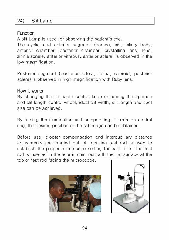
94
24) Slit Lamp
Function
A slit Lamp is used for observing the patient’s eye.
The eyelid and anterior segment (cornea, iris, ciliary body,
anterior chamber, posterior chamber, crystalline lens, lens,
zinn’s zonule, anterior vitreous, anterior sclera) is observed in the
low magnification.
Posterior segment (posterior sclera, retina, choroid, posterior
sclera) is observed in high magnification with Ruby lens.
How it works
By changing the slit width control knob or turning the aperture
and slit length control wheel, ideal slit width, slit length and spot
size can be achieved.
By turning the illumination unit or operating slit rotation control
ring, the desired position of the slit image can be obtained.
Before use, diopter compensation and interpupillary distance
adjustments are married out. A focusing test rod is used to
establish the proper microscope setting for each use. The test
rod is inserted in the hole in chin-rest with the flat surface at the
top of test rod facing the microscope.
95
Maintenance Checklist
Care and
Handling
• Remove dust from the mirror and eye piece lens
using camel hair brush. Finger marks can be
removed if necessary with minimum isopropyl alcohol
and a cotton swab. Dry with a facial tissue.
• Clean exterior surfaces especially the joystick glide
plate by wiping with a soft, dry cloth. Do not use
commercial or household cleaners.
Visual
checks
• If the glass envelope is blackening, replace the
Halogen lamp. .
Function
Checks
• Slit width control adjustment - loosen or tighten the
small screw at the center of the control to change
the amount of force required to turn the knob.
Should be tight enough to ensure that the slit does
not close spontaneously.
• Check the applanation tonometer at 0 g, 2 g and 6 g
positions.
• See the cone prism through left eyepiece and check
whether cone prism is located at the center. If not,
adjust the cone position of vertical and horizontal
direction.
• Slit lamp blades should close without overlapping
and open with parallel edges.
Troubleshooting
Fault Possible causes Solution
1
No illumination. Power cable,
switch, fuse, bulb
socket or bulb is
damaged.
Check and replace
damaged part.
2
Slit light is too
dim
Bulb is not correctly
inserted or Voltage
selector setting is
incorrect.
Insert bulb correctly,
set Voltage selector to
the correct position.

96
25) Centrifuge
Function
Centrifuges are used to fasten the sedimentation of substances
in liquids. In medical laboratories specimen may be blood, urine
etc. In the centrifuge, test tubes containing specimen are placed
into buckets which are then rotated at high speeds or RPM
(rotations per minute) for a pre-determined time. The
substances in the test tubes are deposited in the order of weight,
the heaviest element being the first to settle.
How it works
The brackets holding the buckets are coupled to the shaft of a
motor which then rotates the shaft. The motor is normally a
universal one with a variable speed mechanism. A timer is also
incorporated in the circuit which cuts out power to the motor
after a pre-set time by the user elapses. The two parameters
being variable make it possible for various time/speed
combinations to be applied to a varied range of specimen.
A safety feature is incorporated by the use of door switches. The
switch completes the circuit only when the lid is closed to protect
fingers from injuries that can be caused by the fast spinning
head of the centrifuge.
Some larger centrifuges are equipped with an electrical or
mechanical braking system for halting rotation’
Magnetic door locks in conjunction with centrifugal switches
ensure that the lid cannot be opened as long as the head is
rotating.
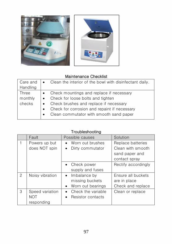
97
Maintenance Checklist
Care and
Handling
• Clean the interior of the bowl with disinfectant daily.
Three
monthly
checks
• Check mountings and replace if necessary
• Check for loose bolts and tighten
• Check brushes and replace if necessary
• Check for corrosion and repaint if necessary
• Clean commutator with smooth sand paper
Troubleshooting
Fault Possible causes Solution
1
Powers up but
does NOT spin
• Worn out brushes
• Dirty commutator
Replace batteries
Clean with smooth
sand paper and
contact spray
• Check power
supply and fuses
Rectify accordingly
2 Noisy vibration • Imbalance by
missing buckets
• Worn out bearings
Ensure all buckets
are in place
Check and replace
3
Speed variation
NOT
responding
• Check the variable
• Resistor contacts
Clean or replace

98
26) Microscope
Function
Microscopes are indispensable in medical laboratories. They
enable the investigation of specimen (blood, urine etc.) for the
presence of parasites or other abnormalities.
The microscope is able to achieve this by producing magnified
images of specimen examined through it by means of multiple
lens arrangement.
How it works
A microscope consists of two lenses (the objective and the eye
piece) and a light source with a condenser. Rays from a light
source are directed into a condenser which then brings them to
a common focus on the specimen. The light rays then pass
through the objective and produce a primary image in the focal
plane of the eye piece. The eye piece magnifies the primary
image and brings it into focus with the retina of the eye.
The objective and eye piece are systems of lenses where the
distance from each other is fixed by the mechanical length of
the tube. To adjust to form a clear image, either the specimen
stage or tube as a whole has to be moved by means of coarse
and fine adjustment drives.
The light source of a microscope can
be either natural or artificial light.
99
Maintenance Checklist
Storage • Should be kept in a dry room at temperature
between 5oC to 35oC
After use cover it with dust covers
Care and
Handling
• Dust can be brushed off with a small paint bush
• Clean dirty lenses with lens tissue or soft clean
cloth. Breathe on the lens before wiping it.
• If the pollution of the lenses is heavy use 2 to 3
drops of xylene on tissue paper
• Check all cleaned lenses with a magnifier
( inverted eye piece)
• Clean oil immersion objective immediately after
use with absorbent paper
• Clean the body and housing with a soft cloth
• Apply petroleum jelly on the rack and pinion when
required
Troubleshooting
Fault Possible causes Solution
1
Light source
bulb NOT
lighting
• Check the bulb
• Intensity knob
stuck on minimum
Replace if blown
Check the knob and
rod assembly and
clean
• Check the light
circuit fuses
Replace if blown
• Check the integrity
of the transformer
Replace if defective
2
Descending
stage
Loose or dirty pinion
and rack
Clean, lubricate and
tighten the rack
Check bearings
between the stage
and limb
Clean and lubricate
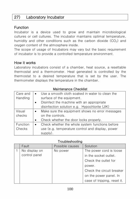
100
27) Laboratory Incubator
Function Incubator is a device used to grow and maintain microbiological
cultures or cell cultures. The incubator maintains optimal temperature,
humidity and other conditions such as the carbon dioxide (CO2) and
oxygen content of the atmosphere inside.
The scope of usage of Incubators may vary but the basic requirement
of incubator is to provide a controlled temperature environment.
How it works Laboratory incubators consist of a chamber, heat source, a resettable
thermostat and a thermometer. Heat generated is controlled by the
thermostat to a desired temperature that is set by the user. The
thermometer displays the temperature in the chamber.
Maintenance Checklist
Care and
Handling
• Use a smooth cloth soaked in water to clean the
surface of the equipment.
• Disinfect the machine with an appropriate
disinfection solution e.g. Hypochlorite (JIK)
Visual
checks
• Make sure the equipment shows no error messages
on the controls.
• Check whether the door locks properly.
Function
Checks
• Check whether the whole system functions before
use (e.g. temperature control and display, power
supply).
Troubleshooting
Fault Possible causes Solution
1
No display on
control panel
No power The power cord is loose
in the socket outlet.
Check the outlet for
power.
Check the circuit breaker
on the power panel. In
case of tripping, reset it.
101
Check that the main
power switch on the
incubator is turned on.
Check for any blown
fuses.
2
High temperature
alarm flushes
Faulty thermostat
Check if temperature
probe is well connected
Check whether the
thermostat is able to
switch on and off
3
Oxidation forming
on the interior
surfaces
Use of high
concentrated
detergent.
Clean the interior surface
with soft water
4
Temperature
display is drifting
Location effect Check the incubator
location.
5 Inside
temperature is
NOT equal to the
display
temperature.
Needs calibration
Location effect
Verify the calibration
procedure.
Check the location of
the incubator.
6 Temperature NOT
controlling at set
point
Fault with set
point
Chambers
circulated with
cold air
Check the set point
Close the doors for a
minimum of 30-40
minutes
7 Display on but NO
temperature rise
Fault on the
Thermostat
Fault on the
Element
Check thermostat
whether it’s okay if not
replace
Check element, if blown
replace
8 Temperatures
take long to reach
the set
temperature
Faulty door
system
Check the gasket, if
damaged replace.
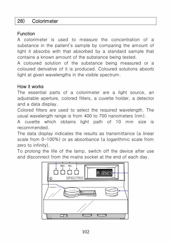
102
28) Colorimeter
Function
A colorimeter is used to measure the concentration of a
substance in the patient’s sample by comparing the amount of
light it absorbs with that absorbed by a standard sample that
contains a known amount of the substance being tested.
A coloured solution of the substance being measured or a
coloured derivative of it is produced. Coloured solutions absorb
light at given wavelengths in the visible spectrum.
How it works
The essential parts of a colorimeter are a light source, an
adjustable aperture, colored filters, a cuvette holder, a detector
and a data display.
Colored filters are used to select the required wavelength. The
usual wavelength range is from 400 to 700 nanometers (nm).
A cuvette which obtains light path of 10 mm size is
recommended.
The data display indicates the results as transmittance (a linear
scale from 0-100%) or as absorbance (a logarithmic scale from
zero to infinity).
To prolong the life of the lamp, switch off the device after use
and disconnect from the mains socket at the end of each day.

103
Maintenance Checklist
Care and
Handling
• Clean the equipment with a soft cloth soaked in a
mild disinfection reagent
• Clean the cuvette holder
Visual
checks
• Check the functionality of the bulbs.
• Check that there is no mechanical damage
• Check that the cuvette is free of scratches and
finger marks
Function
Checks
• Switch ON/OFF and change the filters smoothly
• Check that the correct type of cuvette is in use
• Check that the display is functional when switched
ON
Troubleshooting
Fault Possible causes Solution
1
The machine
does NOT
get power
Faulty power out let
socket
Power cord loosely
connected
Blown fuses
Check the power socket,
if faulty, replace.
Fix the power cord.
Replace fuses of the
same rating.
2
The
machine
powers but
no light
Blown bulb Replace the bulb of the
same rating.
3 The machine
is NOT
zeroing
Machine is due for
calibration
Dust accumulation
on the light filter
Carry out calibration with
a standard medium
Clean the filters.

104
29) Haematology Analyzer
Function
A Haematology analyzer is an automatic multi parameter blood
cell counter for in vitro diagnostic use in clinical laboratories. It
performs speedy and accurate analysis of parameters in blood
and detects the abnormal samples. The instrument displays
abnormal analysis data with abnormal marks attached on the
LCD screen. Displayed analysis data allows detecting those
samples which are outside the tolerance and need further
analysis and consideration. Whole blood and pre-diluted blood
can be analyzed.
How it works
The white blood cell (WBC) count is
measured by the WBC detector block using
DC detection method. The red blood cell
(RBC) count and platelets are taken by the
RBC detector block, also using the DC
detection method. The HGB detector block
measures the hemoglobin concentration
using the non-cyanide hemoglobin method.
Maintenance Checklist
Caring and
Handling
• Clean the transducer (TD) chamber and diluted
sample line daily(Execute shut down).
• Clean the sample rotary valve (SRV) tray weekly.
• Clean the waste chamber (rinse sequence) monthly
or after every 2500 samples.
• Clean the transducer (rinse sequence) monthly or
after every 2500 samples.
• Clean the sample rotary valve (SRV) every 3 months
or after 7500 samples. SRV life time is 5 years
• Clean the rinse cup as needed.
• Clean the WBC/RBC transducer aperture as needed.
105
Visual
checks
• Check trap chamber level daily and discard if
necessary.
• Auto rinse as needed.
• Replace the waste tank as needed.
Function
Checks
• Perform a reagent replacement sequence
• Auto rinse with background check sequence
• Check settings sub-menu for system set up
• Perform the waste chamber cleaning sequence
• Perform the transducer cleaning sequence
• Perform transducer fluid draining sequence (for clog
removal)
• Check status display
1. Hemoglobin (HGB) convert (real time)
2. Pressure and Vacuum (real time)
3. Unit operation counter
• Check paper feed (optional built-in printer)
Troubleshooting
Fault Possible causes Solution
1
Alarm
sounds and
an error
message is
displayed.
Pressure or vacuum, is
outside range.
Air bubbles in the system.
Clogging in transducer
aperture(s)
Press [HELP] key
on keyboard to
stop the alarm
and change over
to the HELP
screen that shows
what actions to
take against the
error.

106
30) CD4 Counter, Flow Cytometer Type
Function
CD4 counter uses flow Cytometry technology that simultaneously
measures/counts and analyses multiple characteristics of single
cells or particles such as CD4 (One of the lymphocyte).The CD4
count data provides important information for staging and
monitoring patients infected with HIV/AIDS. The software
provides an automated analysis without operator’s intervention.
The normal CD4 count is 1,000 cells /mm3 and this count is
lower for HIV infected patients.
How it works
The tissue sample is broken up into single cells and held in a
test tube, which is placed into the flow cytometer. The liquid
containing the cells is drawn up from the test tube and pumped
to the flow chamber (flow cell). Cells flow through the flow
chamber one at a time very quickly and are presented to one or
more light sources (Lasers).
A small laser beam of very bright light hits the cells as they pass
through the flow chamber. The pattern of light scattering is
dependent on cell size and shape giving relative measurements
of these cellular morphological characteristics as cells flow
through the beam. Forward scatter measures light scattered in
the direction of the laser path and measures the size of the cell.
Side scatter measures scattered light at 90 degrees to the laser
path and measures the cell granularity.
The light detector processes the light signals and sends the
information to the computer. Each type of cell in the immune
system has a unique combination of forward and side scatter
measurements, allowing count of number of each type of cell.
Filters are used to direct the light emitted by the fluorochromes
to the colour detectors. The fluorochromes attached to the cells
absorb light and then emit a specific colour of light depending

107
on the type of fluorochrome. The colour detectors (PMT’s)
collect the different colours of light emitted by the fluorochromes.
The electronics in the
cytometer amplify and
process the resulting data.
They convert analogue
data to digital data which is
stored in the computer.
This data from the light
detector and the colour
detectors is analysed
from the computer and
plotted on histograms.
Maintenance Checklist
Care and
Handling
• Unplug, clean external surfaces with a damp cloth
with cleaning solution containing alcohol for example
70% ethanol, Deionized water and wipe surfaces
with a clean, dry cloth
Visual
checks
• Check that all parts are there and correctly fitted
• Check that the mains cable has no damage and if
damaged replace
• Check that the air filter is free of dust and if clogged
wash clean with water, dry and reinstall or replace
• Check the level of sheath fluid in the reservoir
• Check the level of waste in waste reservoir , dispose
of if necessary
Function
Checks
• Check photo multiplier tube (PMT) voltage
adjustment
• Check time – delay calibration
• Check fluorescence compensation adjustment
• Carry out sensitivity testing

108
Troubleshooting
Fault Possible causes Solution
1
Flow cell NOT
filling
No sheath pressure Check for leaks or
cracks in the sheath
reservoir. Replace it, if
needed.
Tighten the sheath
cap.
Verify the vent valve is
in forward
2
No events
displayed and
status =
READY
Communication
failure between
computer and
instrument.
Turn off the computer
and instrument; Turn
on the instrument,
then the computer.
3
No events
displayed and
status =
READY
No sample in the
sampler tube
Add sample or install
new sample tube
4
Scatter
parameters
distorted
Air bubble in flow
cell
Incorrect instrument
settings
Prime the fluidics
Press PRIME
Rerun BD FACSComp
5 Time –delay
calibration fails
Empty sheath
reservoir.
Air in sheath filter
Air bubble in the
flow cell
Fill the sheath
reservoir
Vent air from the
sheath filter
Prime the fluidics
6 Sample tube
NOT
pressurizing
Fluid mode not in
RUN
Cracked sample
tube
Worn Loader seal
Press RUN
Replace the sample
tube
Replace the seal
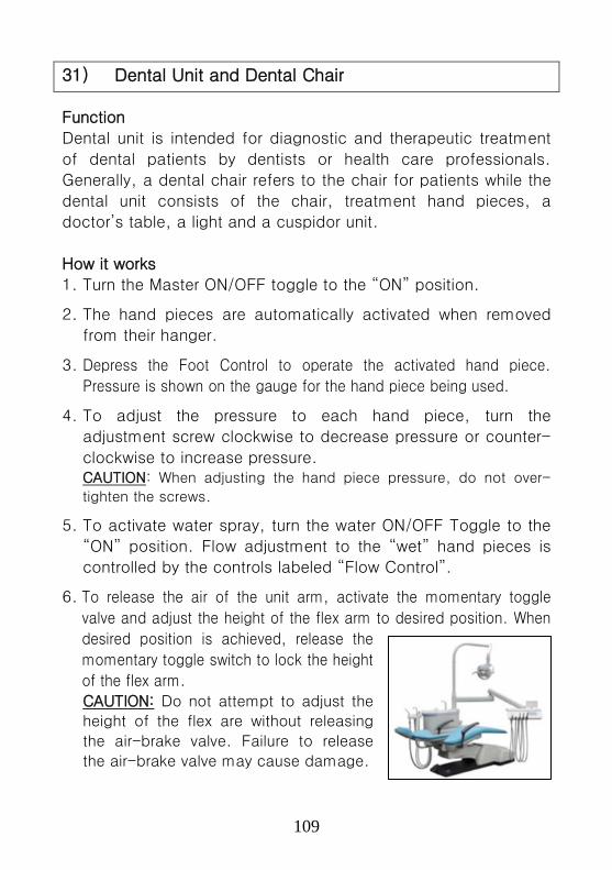
109
31) Dental Unit and Dental Chair
Function
Dental unit is intended for diagnostic and therapeutic treatment
of dental patients by dentists or health care professionals.
Generally, a dental chair refers to the chair for patients while the
dental unit consists of the chair, treatment hand pieces, a
doctor’s table, a light and a cuspidor unit.
How it works
1. Turn the Master ON/OFF toggle to the “ON” position.
2. The hand pieces are automatically activated when removed
from their hanger.
3. Depress the Foot Control to operate the activated hand piece.
Pressure is shown on the gauge for the hand piece being used.
4. To adjust the pressure to each hand piece, turn the
adjustment screw clockwise to decrease pressure or counter-
clockwise to increase pressure. CAUTION: When adjusting the hand piece pressure, do not over-
tighten the screws.
5. To activate water spray, turn the water ON/OFF Toggle to the
“ON” position. Flow adjustment to the “wet” hand pieces is
controlled by the controls labeled “Flow Control”.
6. To release the air of the unit arm, activate the momentary toggle
valve and adjust the height of the flex arm to desired position. When
desired position is achieved, release the
momentary toggle switch to lock the height
of the flex arm. CAUTION: Do not attempt to adjust the
height of the flex are without releasing
the air-brake valve. Failure to release
the air-brake valve may cause damage.
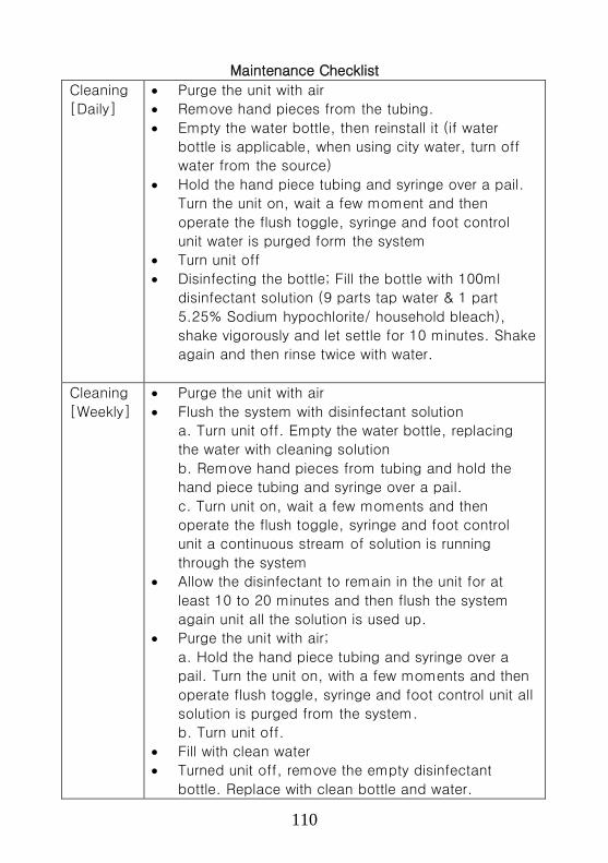
110
Maintenance Checklist
Cleaning
[Daily]
• Purge the unit with air
• Remove hand pieces from the tubing.
• Empty the water bottle, then reinstall it (if water
bottle is applicable, when using city water, turn off
water from the source)
• Hold the hand piece tubing and syringe over a pail.
Turn the unit on, wait a few moment and then
operate the flush toggle, syringe and foot control
unit water is purged form the system
• Turn unit off
• Disinfecting the bottle; Fill the bottle with 100ml
disinfectant solution (9 parts tap water & 1 part
5.25% Sodium hypochlorite/ household bleach),
shake vigorously and let settle for 10 minutes. Shake
again and then rinse twice with water.
Cleaning
[Weekly]
• Purge the unit with air
• Flush the system with disinfectant solution
a. Turn unit off. Empty the water bottle, replacing
the water with cleaning solution
b. Remove hand pieces from tubing and hold the
hand piece tubing and syringe over a pail.
c. Turn unit on, wait a few moments and then
operate the flush toggle, syringe and foot control
unit a continuous stream of solution is running
through the system
• Allow the disinfectant to remain in the unit for at
least 10 to 20 minutes and then flush the system
again unit all the solution is used up.
• Purge the unit with air;
a. Hold the hand piece tubing and syringe over a
pail. Turn the unit on, with a few moments and then
operate flush toggle, syringe and foot control unit all
solution is purged from the system.
b. Turn unit off.
• Fill with clean water
• Turned unit off, remove the empty disinfectant
bottle. Replace with clean bottle and water.

111
• Disinfectant solution; Use 100ml of disinfectant
solution.
Visual
checks
• When the compressor is OK, we expect lighting
system to be OK.
Function
Checks
When the power is on you check
• Hand pieces, Air compressor, Foot switch
• Check knobs are operational
Troubleshooting
Fault Possible causes
1
Hand piece
lacks Power
Check regulator adjustment (80psi)
Check hand piece pressure adjustment on
control block
Pinched supply Bad hand piece gasket at connection with tubing
Defective hand piece
2
Water coolant
does NOT shut
off when foot
switch is
released
Adjust air pressure to 80psi – Water pressure
to 40psi
Foot control is not exhausting
Defective water relay in valve
3
More than one
hand piece is
operating
Hand piece is not completely in the hanger Improve adjustment of pilot valve in the hanger.
Kinked or pinched signal line from the pilot valve.
4
Insufficient water
coolant
Adjust coolant flow valve
Water filter may be plugged
Plugged hand piece
Kinked or pinched tubing
Improper adjustment of water relay
5 Water coolant is
running from
hand piece while
in holder
Water pressure is too high
Air pressure is too low
Hand piece holder out of adjustment
6 Water coolant is
running
continuously
Purge switch is on
Water pressure is too high
Hand piece holder out of adjustment
Improper adjustment of water relay

112
32) Solar Photovoltaic (PV) System
Function
Solar PV systems generate electricity to operate recommended
appliances (e.g. lamps for lighting, ultrasound scanner, oxygen
concentrator, suction machine, computer, etc.)
How it works
A solar PV system uses sunlight to generate electricity.. A solar PV
system consists of the following main components:
Solar panel/module:
It receives sunlight and converts it into electricity to charge
the battery.
Charge controller (Regulator):
It controls battery charging and discharging.
It prevents overcharge (too much current into the battery) of
the battery by automatically disconnecting the solar panels
when the battery is fully charged.
It disconnects loads to prevent battery discharge (draining of
the battery) beyond safe levels.
Battery:
It stores electricity generated by the solar panels for use
when required..
Inverter:
It converts the direct current (DC) from the battery into
alternating current (AC) and supplies it to operate AC
appliances.
AC and DC loads (Appliances):
These are the AC and DC loads that use electricity.
Other Accessories (Distribution board, Circuit breakers, Cables):
These are used to interconnect, control and protect different
components against damage.
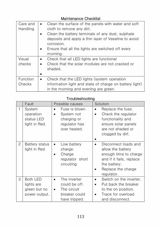
113
Maintenance Checklist
Care and
Handling
• Clean the surface of the panels with water and soft
cloth to remove any dirt.
• Clean the battery terminals of any dust, sulphate
deposits and apply a thin layer of Vaseline to avoid
corrosion.
• Ensure that all the lights are switched off every
morning.
Visual
checks
• Check that all LED lights are functional
• Check that the solar modules are not cracked or
shaded.
•
Function
Checks
• Check that the LED lights (system operation
information light and state of charge on battery light)
in the morning and evening are green.
Troubleshooting
Fault Possible causes Solution
1
System
operation
status LED
light in Red.
• Fuse is blown.
• System not
charging or
regulator has
over heated.
• Replace the fuse.
• Check the regulator
functionality and
ensure solar panels
are not shaded or
clogged by dirt.
•
2
Battery status
light in Red
• Low battery
charge.
• Charge
regulator short
circuiting
• Disconnect loads and
allow the battery
enough time to charge
and if it fails, replace
the battery.
• Replace the charge
regulator.
3
Both LED
lights are
green but no
power output.
• The inverter
could be off.
• The circuit
breaker could
have tripped.
• Switch on the inverter.
• Put back the breaker
to the on position.
• Trace for overload
and disconnect.

114
Annexes
Annex 1: Standard Floor Plan of a Regional Workshop
Annex 2: Recommended WS Tools, Test Equipment and
Furniture
Annex 3: Stickers Form, Equipment Condition A-F
Annex 4: Medical Equipment Inventory Form
Annex 5: Template of Work Plan Preparation
Annex 6: 5S Activity’s Instruction for RWs
Annex 7: Quarterly Report General Form
Annex 8: Job Card Form
Annex 9: Support Supervision & Monitoring Sheet
Annex 10: Complaints Form

115
Annex 1: Standard Floor Plan of a Regional Workshop

116
Annex 2: Recommended WS Tools, Test Equipment and Furniture No. Equipment Name Qt’y
Tools and Test Equipment
1 Tool Kit, Mechanical (*) 2
2 Tool Kit, Electrician (*) 2
3 Tool Kit, Electronics (*) 2
4 Tool Kit, Medical Equipment (*) 2
5 Tool Kit, Plumber (*) 2
6 Tool Kit, Refrigeration (*) 2
7 Welding machine, heavy duty 1
8 Workshop stool 4
9 Workshop protective wear (pant and shirt) 6
10 Workshop shoes 6
11 Heavy duty gloves 6
12 Automated electrical safety analyzer 1
13 Ultrasound electrical safety transducer leakage current tester 1
14 Portable oxygen analyzer 1
15 2 Drawer work bench with vice No. 5 1
16 Engraving machine, electric, heavy duty 1
17 13mm chuck, reversible, variable speed, Drilling machine, with
hammer function, electrical, hand held 1
18 13mm chuck, reversible, 2 speed, Portal drilling machine,
cordless with spare battery and charger 1
19 Vice No. 3 1
20 Portable Generator set, 5KVA minimum 1
21 Dual DC regulated power supply 1
22 3 Phase tester 1
23 Mega tester 1
Office Furniture
24 Office Chair 2
25 Chair 10
26 Desk with lockable drawers 3
27 Photocopier 1
28 Filing cabinet 3
29 6 Persons conference table 1
30 Shelves 3
31 White board 1600cm x 110cm 1
Note: (*) The details of the Kits are described in the following pages.

117
No. 1/Tool Kit, Mechanical
No. Description (Tool Kit, Mechanical) Qt’y
1 Cutter, side, large 1
2 G-clamp 1
3 Pliers, long nose, 170mm 1
4 Screwdriver/tester, Voltage tester 1
5 Box, tool, steel, big, 4 tray, cantilever, 550 x 220 x 215mm (l x w x h) 1
6 Oil can, 125ml, metal with pump 1
7 Hydrometer/battery electrolyte tester 1
8 Brush, steel, hand, 290mm; 37mm; 4 rows 1
9 Chisel and punch set, 6 pc 1
10 File set flat/square/half round/round, coarse and fine, 200mm 1
11 Hacksaw, standard, 470mm 1
12 Hammer, ball pein, 500g/1ib; 350mm 1
13 Hammer, nylon, 280mm; diam:32mm 1
14 Key, hexagon, metric, set, 9pc, 1.5 – 10mm 1
15 Machine, drilling, hand, 2 speed, 1 – 12mm 1
16 Pliers, water pump, standard, 225mm 1
17 Punch, nail, 150 x 5 mm 1
18 Letter punch set, A-Z 1
19 Number punch set, 0-9 1
20 Screwdriver, flat, blade: 3.5mm; shaft:75mm 1
21 Screwdriver, flat, blade: 5.5mm; shaft 100mm 1
22 Screwdriver, flat, blade: 8mm; shaft: 250cm 1
23 Screwdriver, star, No. 1x, Diam: 4 mm; shaft 75mm 1
24 Screwdriver, star, No. 2x, Diam: 6mm; shaft 100mm 1
25 Screwdriver, star, No. 3x., Diam: 8mm; shaft: 150mm 1
26 Spanner, flat, metric, set, 15 pc, 6 – 32mm 1
27 Spanner, ring/flat, metric, set, 16pc, 5 – 25mm 1
28 Spanner, box/socket, metric set, 16 pcs, 6-33mm 1
29 Wrench, self gripping, Max: 50mm 1
30 Wrench, socket, set, large, 10 – 32mm; ½” square drive 1
31 Wrench, chain, diam.: 7 – 2200mm 1
32 Tap and die set, imperial 1
33 Tap and die set, metric 1
34 Wire brush 1
35 Reamer set 1
36 Steel rule, marked, metric: 300mm 1
37 Tape measure, Steel, 3m 1

118
No. 2/Tool Kit, Electrician No. Description (Tool Kit, Electrician) Qt’y
1 Cutter, side, large, Max. size wire: 2.0mm; L = 210mm 1
2 Multi-meter, basic, digital, Like fluke 11 1 3 Bit, drill, concrete, hammer operated, 3.5/4.5/5.0/6.0 mm, with handle 1
4 Hammer, club, 42 x 42 x 110mm 1
5 Screwdriver, flat, insulated, blade 2.5mm; shaft 75mm 1
6 Screwdriver, flat, insulated, blade 4.0mm; shaft 100mm 1 7 Screwdriver, star, insulated, blade 2.5mm; shaft 75mm 1
8 Screwdriver, star, insulated, blade 4.0mm; shaft 100mm 1 9 Screwdriver/ mains tester, blade 4mm; shaft: 100mm, 100–500V 1
10 Stripper, Wire, Standard, 170mm 1
11 Knife, trimming, retractable blade 1 12 Pen, marking, waterproof, medium 1
13 Tape measure, Steel, 3m 1
14 Box, tool, steel, big, 4 tray, cantilever, 550 x 220 x 215mm (l x w x h) 1 15 Chisel, channeling 1
16 Chisel set complete with floorboard 1
17 Cutter, pipe, 3 – 30mm 1 18 File set flat/square/half round/round, coarse and fine, 200mm 1
19 Hacksaw, Junior 1 20 Hacksaw, standard, 470mm 1
21 Light, torch, rubber coated, 2 batteries LR20, 3V 1
22 Pliers, combination, 203mm / 8” 1 23 Pliers, long nose 1
24 Punch, centre, diam: 6mm; 1 = 115mm 1 25 Reamer, pipe 1
26 Screwdriver, flat, chubby, blade: 5.5mm; shaft: 40mm 1 27 Screwdriver, flat, long, blade: 5.mm; shaft: 200mm 1
28 Screwdriver, flat, screw gripping, blade: 6mm; shaft: 200mm 1 29 Screwdriver, Phillips, chubby, No. 2x Diam: 5.0mm; shaft: 40mm 1
30 Screwdriver, Pazidriv, No. 1, 75mm 1 31 Screwdriver, Pozidriv, No. 2, 100mm 1
32 Spanner, adjustable, medium, 205mm / 8”; jaw:27m 1 33 Spectacles, safety 1
34 Wrench, pipe, small, 229mm / 9” 1 35 Malet Hammer 1 36 Claw Hammer 1 37 Wire brush 2
38 Grip pliers, adjustable, set 1 39 Hygrometer 1 40 Portable hand drill, cordless with rechargeable battery & charger 1 41 Allen keys set (metric & imperial) 1 42 Circlip plier set 1

119
No. 3/Tool Kit, Electronics No. Description (Tool Kit, Electronics) Qt’y
1 Cutter, side, small size, L=125 1
2 De-soldering tool, standard 1
3 Dispenser, solder 1
4 Iron, soldering, medium, general, 30W / 220V; tip diam: 6mm 1
5 Multi-meter, digital, Like fluke 79 series, Resol: 3.5 digit 1
6 Pliers, long nose, 170mm 1
7 Screwdriver / mains tester, blade: 4mm; shaft: 100mm, 100 – 500V 1
8 Stripper, wire, standard, 170mm 1
9 Tools, trimming, set 1
10 Wick, de-solder 1
11 File, needle, set, 6pcs: 160mm 1
12 Knife, trimming, retractable blade 1
13 Tweezers, 130mm; tips: 1mm 1
14 Box, tool, brief-case type, 500 x 380w x 150h mm 1
15 File, half round, second cut, 150mm 1
16 Hacksaw, Junior 1
17 Hammer, ball pein, 100gr/1 oz 1
18 Key, hexagon, metric, set, 9pc, 1.5 – 10mm 1
19 Key, hexagon, set, imperial, 9pc, 5/64 – 3/8” 1
20 Magnifying glass, pocket type 1
21 Mirror, inspection 1
22 Pliers, combination; 180mm / 7” 1
23 Screwdriver, flat, blade: 3.5mm; shaft 75mm 1
24 Screwdriver, flat, blade: 5.5mm; shaft 100mm 1
25 Screwdriver, flat, blade: 6.5mm; shaft 100mm 1
26 Screwdriver, flat, long shaft, blade: 4.0mm; shaft 250mm 1
27 Screwdriver, flat, screw gripping, blade: 6mm; shaft 200mm 1
28 Screwdriver, Pozidriv. No. 0, 60mm 1
29 Screwdriver, Pozidriv. Long shaft, No. 1, 250mm 1
30 Screwdriver, Pozidriv. Long shaft, No. 2, 250mm 1
31 Screwdrivers, jeweller’s, set, crosshead 1
32 Screwdrivers, jeweller’s, set, flat blade 1
33 Shears, light duty, L 190 D 4.5 1
34 Spanner, adjustable, small, 155mm / 6”, jaw: 20mm 1
35 Spanner, ring/flat, metric, set, 8pc, 8 – 19mm 1
36 Brush, cleaning, 12mm, 260mm 1
37 Snipper set 1
38 Allen key set (metric & imperial) 1
39 Precision screw driver set 1
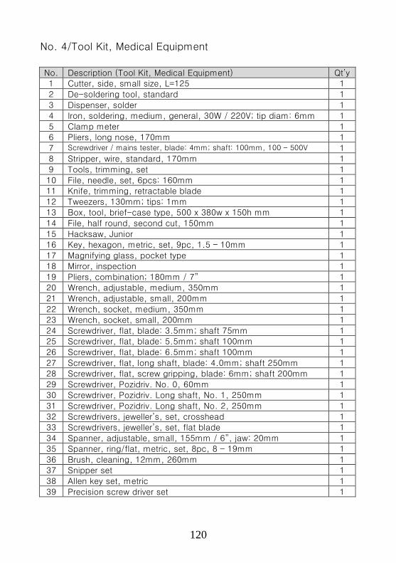
120
No. 4/Tool Kit, Medical Equipment
No. Description (Tool Kit, Medical Equipment) Qt’y 1 Cutter, side, small size, L=125 1
2 De-soldering tool, standard 1
3 Dispenser, solder 1 4 Iron, soldering, medium, general, 30W / 220V; tip diam: 6mm 1
5 Clamp meter 1 6 Pliers, long nose, 170mm 1
7 Screwdriver / mains tester, blade: 4mm; shaft: 100mm, 100 – 500V 1 8 Stripper, wire, standard, 170mm 1
9 Tools, trimming, set 1
10 File, needle, set, 6pcs: 160mm 1 11 Knife, trimming, retractable blade 1
12 Tweezers, 130mm; tips: 1mm 1 13 Box, tool, brief-case type, 500 x 380w x 150h mm 1
14 File, half round, second cut, 150mm 1
15 Hacksaw, Junior 1 16 Key, hexagon, metric, set, 9pc, 1.5 – 10mm 1
17 Magnifying glass, pocket type 1 18 Mirror, inspection 1
19 Pliers, combination; 180mm / 7” 1 20 Wrench, adjustable, medium, 350mm 1
21 Wrench, adjustable, small, 200mm 1
22 Wrench, socket, medium, 350mm 1 23 Wrench, socket, small, 200mm 1
24 Screwdriver, flat, blade: 3.5mm; shaft 75mm 1 25 Screwdriver, flat, blade: 5.5mm; shaft 100mm 1
26 Screwdriver, flat, blade: 6.5mm; shaft 100mm 1
27 Screwdriver, flat, long shaft, blade: 4.0mm; shaft 250mm 1 28 Screwdriver, flat, screw gripping, blade: 6mm; shaft 200mm 1
29 Screwdriver, Pozidriv. No. 0, 60mm 1 30 Screwdriver, Pozidriv. Long shaft, No. 1, 250mm 1
31 Screwdriver, Pozidriv. Long shaft, No. 2, 250mm 1
32 Screwdrivers, jeweller’s, set, crosshead 1 33 Screwdrivers, jeweller’s, set, flat blade 1
34 Spanner, adjustable, small, 155mm / 6”, jaw: 20mm 1 35 Spanner, ring/flat, metric, set, 8pc, 8 – 19mm 1
36 Brush, cleaning, 12mm, 260mm 1 37 Snipper set 1
38 Allen key set, metric 1
39 Precision screw driver set 1

121
No. 5/Tool Kit, Plumber
No. Description (Tool Kit Plumber) Qt’y
1 Bit, drill, concrete, set, hammer operated, 3.5, 4.5, 5, 6mm;
with handle 1
2 Level, Spirit, L = 50cm 1
3 Trowel, pointing, 150mm 1
4 Iron, brazing/soldering, large, 300W / 220V 1
5 Tape measure, steel, 3m 1
6 Box, tool, steel, big, 4 tray, cantilever, 550 x 220 x 215mm (l x
w x h) 1
7 Chisel, cold, 16mm x 250mm 1
8 Chisel, floorboard 1
9 Cutter, pipe, 3 – 30mm 1
10 Hacksaw, junior 1
11 Hacksaw, standard, 470mm 1
12 Lamp, soldering, paraffin, 0.5 litre 1
13 Mallet, bossing, 60mm 1
14 Mallet, tinmans, 60mm 1
15 Pliers, combinations, 203mm / 8” 1
16 Pliers, water pump, standard, 225mm 1
17 Rule, s/s, 300mm 25mm wide 1
18 Shears, metal 1
19 Wrench, footprints, 220mm 1
20 Hammer, plumbers’ 500gr 1
21 Hook, shave, triangular 1
22 Plumber’s bob, with line, 100 gr 1
23 Portal Tripod stand 1
24 Pipe cutter 1
25 Wrench, adjustable, medium, 350mm 1
26 Wrench, adjustable, small, 200mm 1
27 Wrench, socket, medium, 350mm 1
28 Wrench, socket, small, 200mm 1
29 Bit, drill, auger, wood, set, 5pc, 6 – 25mm / 125mm 1
30 Brace, bit, ratchet, 4 jaw, 255mm 1

122
No. 6/Tool Kit, Refrigeration
No. Description (Tool Kit, Refrigeration) Qt’y
1 Leak detector, electronic 1
2 Pressure gauge (for R12 & R134a refrigerants) 1
3 Pipe bender set (1/2”, 3/4”, 1” …. 2”) 1
4 Clamp meter 1
5 Flaring swaging tool 1
6 Ratchet spanner set 1
7 Portal brazing cylinder set 1
8 Blower (dust) 1
9 Digital thermometer 1
10 Portable brazing torch (butane) 1
11 Allen keys (metric & imperial) 1
12 Protective goggles 2
13 Portable gas welding kit 1
14 Silicon gun 1
15 Rivet gun 1
16 Tape measure, steel, 5 m 1
17 Electrical drill, with both hammer & reverse functions 1
18 Cordless portal hand drill, with rechargeable batteries 1
19 Digital clipper 1
20 Screw driver set (flat & screw) 1
21 Vacuum pump 1
22 Circlip pliers 1
23 Electrical clumping tool 1
24 Reamer set 1

123
Annex 3: Stickers Form, Equipment Condition A-F
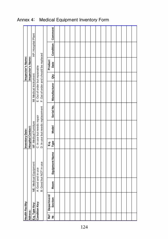
124
Annex 4: Medical Equipment Inventory Form
Heal
th F
acili
ty:
Inve
ntor
y Da
te:
Insp
ecto
r's N
ame:
Adre
ss:
Hosp
ital C
onta
ct:
Insp
ecto
r's N
ame:
E.q.
Typ
e Ke
y:M
E: M
edic
al E
quip
men
tM
F: M
edic
al F
urni
ture
MI:
Med
ical
Inst
rum
ent
HP
: Hos
pita
l Pla
ntCo
nditi
on K
ey:
A: G
ood
and
in u
seC
: In
use
but n
eeds
repa
irE
: Out
of o
rder
but
repa
irabl
eB
: Goo
d bu
t NO
T in
use
D: I
n us
e bu
t nee
ds re
plac
emen
tF:
Out
of o
rder
and
sho
uld
be re
plac
ed
Ref
Nr.
Depa
rtm
ent/
Sect
ion
Room
Equi
pmen
t Nam
eE.
q.Ty
peM
odel
Seria
l No.
Man
ufac
ture
rQ
tyPr
oduc
tDa
teCo
nditi
onCo
mm
ent

125
Annex 5: Template of Work Plan Preparation
Acti
vity
No.
Outp
ut
Descri
ption
Outp
ut
Indic
ato
r(s)
Pla
nned O
utp
ut
Targ
et
Pla
nned A
ctivitie
sto
Deliver
Outp
uts
Activity
Tim
ing
(Q1,
Q2,
Q3,
Q4)
Sourc
eof
Fundin
g
Responsib
leoffic
er
Cost
Item
sC
ost
per
Item
(000's
)
1Num
ber of
technic
ians
and e
ngin
eers
train
ed
Bio
-Medic
al
Engin
eering tra
inin
gconducte
d for 10
Engin
eers
/Technic
ians
Conduct train
ing for
technic
ians in
serv
icin
g a
nd
main
tenance o
fsele
ced e
quip
ment
Q2
GoU
RW
Manager
Sta
fftrain
ing
30,0
00
2M
edic
al
Equip
ment
main
tenance
conditi
on
65%
of ava
ilable
medic
al equip
ment ke
pt
in g
ood c
onditi
on
Pro
cure
assorted
medic
al equip
ment
spare
parts
Q2
GoU
RW
Manager
Equip
ment
Main
te-
nance
300,
000
3Num
ber of
equip
ment
main
tain
ed
Update
d g
uid
elin
es o
nhealth
care
waste
managem
ent and
dis
posal
Conduct m
ain
tenance
visits
to targ
et
hospita
ls a
nd H
CIV
s
Q2,
Q3
GoU
RW
Manager
Tra
vel
inla
nd
3,00
0
4M
inute
s o
fm
eetin
gs h
eld
2 m
eetin
gs p
er ye
ar
Org
anis
e a
nd h
old
RW
managem
ent
com
mitt
ee m
eetin
gs
Q2,
Q4
GoU
Hopita
lDirecto
rTra
vel
inla
nd
40,0
00
373,0
00
Medic
al
Equip
ment
main
tenance
impro
ved
Tota
l fo
r A
ctivity:

126
Annex 6: 5S Activity’s Instruction for RWs
1. What is 5S?
5S is a management tool, which originated from the Japanese
manufacturing sector. It is used as a basic, fundamental,
systematic approach for productivity, quality and safety
improvement in all types of organizations.
5S is literally five abbreviations of Japanese terms with five
initials of S. There are Seiri, Seiton, Seiso, Seiketsu and Shitsuke. In English, 5Ss were translated as Sort, Set, Shine, Standardize and Sustain. These are explained briefly below:
The five steps of Sort-Set-Shine-Standardize-Sustain are a
sequence of activities to improve the work environment to be as
convenient and comfortable as possible and thereby also
improve service contents with respect to preparedness,
standardization and timeliness.
2. Practical hints for five steps
The basic actions and practical hint for implementing5S are
shown in the following page. The principal example and practical
hints are shown in the following page for every step of 5S.
1. Sort Remove unused stuff from your venue of work and reduce clutter
2. Set Organize everything needed in proper order for easy operation 3. Shine Maintain high standard of cleanness 4. Standardize Set up the above three So as norms in every section of your
place by use of Standard Operating Procedures and checklists
5. Sustain Train and maintain discipline of the personnel engaged
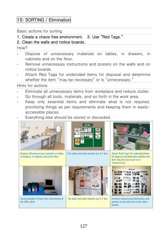
127
1S: SORTING / Elimination
Basic actions for sorting
1. Create a chaos free environment. 3. Use “Red Tags.”
2. Clean the walls and notice boards.
How?
- Dispose of unnecessary materials on tables, in drawers, in
cabinets and on the floor.
- Remove unnecessary instructions and posters on the walls and on
notice boards.
- Attach Red Tags for undecided items for disposal and determine
whether the item “may be necessary” or is “unnecessary.”
Hints for actions
- Eliminate all unnecessary items from workplace and reduce clutter.
- Go through all tools, materials, and so forth in the work area.
- Keep only essential items and eliminate what is not required,
prioritizing things as per requirements and keeping them in easily-
accessible places.
- Everything else should be stored or discarded.
Dispose off unnecessary materials on tables, in drawers, in cabinets and on the floor.
The walls and notice boards use X-Y line. Attach “Red Tags” for undecided items for disposal and determine whether the item “may be necessary” or is “unnecessary.”
Good example of chaos free environment at the office desk.
The walls and notice boards use X-Y line. Remove unnecessary instructions and posters on the wall and on the notice boards.

128
2S: SETTING/ Material Handling
Basic points for setting material handling
1. Zone/area, clear transport routes; 3. Home for each tool;
2. Multi-level shelves and containers;
How?
- Secure transport routes without obstacles that are even and not slippery.
- Provide multi-level shelves or storage racks near the work area for medical
charts and drugs.
- Provide a “home” for medical equipment and work items and mark their
position clearly.
- Use carts, hand-trucks and other wheeled devices when moving materials.
Hints for actions
- Organize everything needed in proper order for ease of operation.
- There should be a place for everything and everything should be in its
place.
- The place for each item should be clearly labeled or demarcated.
- Items should be arranged in a manner that promotes efficient work flow,
with equipment used most often being the most easily accessible.
Clear transport routes with clear mark. Provide multi-level shelves or storage
racks near the work area for medical drugs.
Provide a “home” for each piece of medical equipment.
Use carts, hand-trucks and other wheeled devices when moving materials.
Secure transport routes without obstacles that are even and not slippery.
Provide multi-level shelves for medical charts in the record unit.

129
2S: SETTING/ Workstation changes
Basic points for setting workstation changes
1. Easy reach 3. Comfortable chairs
2. Elbow height
How?
- Place frequently used tools, controls and materials within easy reach of
workers.
- Adjust the working height for each health care worker at elbow level or
slightly below it.
- Allow workers to alternate standing and sitting as much as possible and
provide good adjustable chairs with good backrests.
Hints for actions
- Items should be arranged in a manner that promotes efficient work flow,
with equipment used most often being the most easily accessible.
- Workers should not have to bend repeatedly to access materials.
- Each tool, part, supply, or piece of equipment should be kept close to
where it will be used – in other words, straightening the flow path.
Place frequently used tools and materials within easy reach of workers
Adjust the working height for each health care worker at elbow level or slightly below it.
Provide good adjustable chairs with good backrests.
Place frequently used tools within easy reach
Adjust the working height for each health care worker at elbow level or slightly below it to reach.
Set necessary equipment nearby worksite for easy to reach.

130
2S: SETTING/ Labels, signs, color coding
Basic points for setting labels, signs, color cording
1. Labeling 3. Color coding/numbering
2. Safety signs 4. Signboards/mapping
How?
- Make labels, colors and signs easy to see, easy to read and easy
to understand.
- Provide clear instructions and information necessary for safe,
efficient work.
- Use color coding rules such as for garbage, medical waste and
linen by type.
- Use a board with X-Y axis alignment for sharing medical
information, a 5-S corner display and a map of work areas for
patients.
Hints for actions
- The place for each item should be clearly labeled or demarcated.
- Items should be arranged in a manner that promotes efficient work
flow, with equipment used most often being the most easily
accessible.
Labels should be easy to read and easy to understand.
Clear instructions for operation of the fire extinguisher.
Numbering rules of medical charts for proper setting,
5S corner display by X–Y axis alignment. The place for each item should be clearly
labeled or demarcated. A map of work areas for patients.

131
3S: SHINING/ Regular maintenance and cleanliness
Basic points for Shining
1. Cleanliness 3. Proper maintenance of equipment
2. Waste bin, cleaning tool
How?
- Designate the responsibility for keeping areas clean to staff
members and clean regularly.
- Place waste bins and cleaning tools in the appropriate workplace.
- Inspect and maintain medical Instruments, machines and tools
regularly.
Hints for actions
- Discuss the placement of waste bins in areas where they are needed at
your workplace.
- Regular maintenance keeps your medical equipment productive and safe.
Check all machine parts carefully. In particular, special care is needed for
rotating parts, detachable guards and electrical wires, etc.
- If you find an inexpensive machine, you should check its safety aspects
even more carefully. When accidents occur, costs can be enormous.
- Develop a long-term maintenance plan. For instance, you may check the
machine thoroughly every weekend.
Designate responsibility for keeping the area clean to staff members.
Place waste bins and cleaning tools in the appropriate workplace location.
Inspect and maintain medical instruments, machines and tools regularly.
Cleaning regularly supports daily work tasks. Place waste bins at every point where HWs
undertake procedures. Discuss establishing a standard of cleanliness with staff members.

132
4S: STANDARIZE/ Improving quality of care
Basic points for standardizing
1. Standardized care procedures 4. Establishing hand hygiene
2. Procedures of the equipment 5. Reducing patients’ waiting time
3. Ensuring patients’ privacy
How?
- Establish the protocols of standardized care procedures about each cure
and care, such as maternity, vaccination, medical health checkup.
- Display procedures of the equipment and label clearly what operation is
meant.
- Use partitions, curtains and other arrangement for protection privacy of
persons cared
- Establish hand hygiene procedures and hygienic washing facilities.
- Reducing waiting time for patients at an outpatient room, a laboratory and
a pharmacy.
Hints for actions
- Listing basic clinical procedures makes it easy to find necessary
standardized care procedures for documentation.
- Labels and signs are needed for clear instruction for procedures.
- Encouraging collection of patients’ opinion is essential for improving
quality of care.
The protocols of standardized malaria diagnosis as a flowchart
Instructions for procedures for the use of equipment with operations clearly labeled.
Curtains for protection privacy of persons cared.
Proper hand hygiene procedures and hygienic washing facilities.
A suggestion box helps improve the quality of care.
Reducing waiting times for patients at outpatient departments, laboratories and pharmacies.

133
5S: SUSTAIN/ Teamwork
Basic points for sustaining
1. Tool box meeting 3. Work Improvement Team (WIT), 5S Training
2. Record of accidents and injuries
How?
- Hold a brief meeting before beginning work to plan assignments
and avoid giving excessive workloads to particular staff members.
- Keep records of medical accidents, occupational injuries and
diseases for ensuring both patients and workers' safety.
- Encourage Work Improvement Team (WIT) activities and provide
adequate participatory 5S and safety/health improvement training
to all workers.
Hints for actions
- Record all accidents, absences, sickness, and other health-
related events.
- Plan annual work schedules including sufficient training periods.
Hold a brief meeting before work Keep records of both medical accidents and occupational injuries
Visit 5S team regularly at the workplace
5S training for all staff members Holding monthly WIT meetings helps
maintain 5S activities 5S facilitators organize engaging 5S workshops.
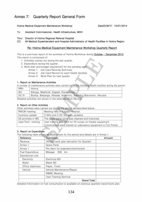
134
Annex 7: Quarterly Report General Form
Hoima Medical Equipment Maintenance Workshop Date(D/M/Y) : 10/01/2014
To: Assistant Commissioner, Health Infrastructure, MOH
Thru: Director of Hoima Regional Referral Hospital
CC: All Medical Superintendent and Hospital Administrator of Health Facilities in Hoima Region
Re: Hoima Medical Equipment Maintenance Workshop Quarterly Report
This is a summary report of the activities of Hoima Workshop during October - December 2013.
This report is composed of:
1. Activities carried out during the last quarter.
2. Expenditure during the quarter.
3. Work plan and budget requirement for the pending work.
Annex 1: Job Card Records Summary
Annex 2: Job Card Record for each health facilities
Annex 3: Work Plan for next quarter
1. Report on Maintenance Activities A number of maintenance activities were carried out in the following health facilities during the period.
RRH Hoima
GH Kiboga, Mashindi, Kagadi, Kiryandongo
HC IV Buliisa, Bwijanga, Kibaale, Kakumiro, Kakindo, Bukomero, Kikuube
Detailed activities are shown in the attached Work Record:
2. Report on Other Activities
Other activities were carried out during the period as described below.
RWCM meeting Meeting held in Kagadi Hospital.
Inventory update 2 GHs and 3 HC IVs were updated.
5S activities in WS The spare parts store was cleaned and improved.
User/Tech. training User training was held for 20 nurses on theater equipment.
2 technicians were trained on Laboratory equipment in Fort Portal.
3. Report on Expenditure
The following table shows all expenditure for the period and details are in Annex 1.
Reference Description Amount
Revenue (Annual work plan allocation for Quarter)
Annex 1 Spare Parts
Annex 1 Per diem for engineers/technicians
Fuel Expenditure Mileage: 690 km
Operational cost
Electricity Electricity Bill
Water Water Bill
Office stationary Paper, Toner
Vehicle Vehicle Maintenance/Repair
RWMC Meeting
User Training Seminar
Grand Total
Detailed information on fuel consumption is available on previous quarterly report/work plan.

135
4. Work Plan and budget requirement for the next quarter
Work plan for the next quarter is attached for perusal. (Annex 2)
The cost of necessary spare parts for pending work is available in the work record. (Annex 1)
Maintenance needs for health facilities is based on the latest health facility equipment inventory
update.
The estimated cost of spare parts for the planned activities is indicated in the list.
Any emergency repair shall be handled on a case by case basis.
Total budget requirement for next quarter activities is summarized below.
Reference Description Amount
Revenue
Annex 1 Spare parts
Annex 3 Per diem for Engineers/Technicians
Annex 3 Fuel
Operational Cost
Past Average Electricity Bill
Past Average Water Bill
Past Average Stationary
Past Average RWMC Meeting
Past Average User Training Seminar
On plan Vehicle Maintenance
Grand Total
5. Urgent issues to note:
1) The maintenance money for the 1st quarter was released late.
2) The mobile workshop vehicle has worn out tyres, but budget is not adequate to purchase tyres.
3) The procurement of spare parts has delayed.
4) Solar panels for blood bank refrigerator in **** HC IV were stolen.
5) **** GH generator starting system circuit board needs replacement.
Compiled By
(Name of WS Manager)
Hoima Regional Workshop Manager

136
Annex 8: Job Card Form
Job Card Number:
Year
Qty Unit Price Total Amount(Ushs)
Note; (1) Cost of spare parts and other costs are for monitoring maintenancce cost only.
Title
Date
Endosed by
Signature
Hospital stamp
New equipment sticker,: A,B,C,D,E,FDepartment Personnel avialbale Comment
Name
HP/RWS/Trip ContingencyOther(identify)
Spare Parts GRAND TOTAL
6
HP/RWS/Trip ContingencyOther(identify)
5HP/RWS/Trip ContingencyOther(identify)
4
HP/RWS/Trip ContingencyOther(identify)
3HP/RWS/Trip ContingencyOther(identify)
2
HP/RWS/Trip ContingencyOther(identify)1
Any other expenses (Casual Labor etc should be described hereName Source of Spares
Spare Parts Used and Other Expenses (1)
Time spent onmaintenance Hrs
Time spent onmaintenance Hrs
Extra work to be done/Advise to the owner(Health Facility)/Findings
Name of Eng/Tech Contact No.Time spent onmaintenance Hrs
Name of Eng/Tech
Name of Eng/Tech
Contact No.
Contact No.
Mnufacturer Country of origin Product Date
Fault Detected:
Work done
A. B. C. D. E. F
JOB CARD
Equipment owner/Health Unit Department Room
Complaint Form No. Sticker on Equipment
Equipment Name Model name Serial No.

137
Annex 9: Support Supervision & Monitoring Sheet
Name of RW ……………………………………..Name of RW Manager ……………………………………..Evaluation Period ………………… Date ………………………………….Name of Evaluator …………………Designation ………………………………….
No. Yes No
1. Is Workshop Space adquate?2. Are the Workshop premises clean?3. Does the Workshop have basic tools and equipment?
1.Does the Workshop maintain Inventory?2.Does the Workshop maintain a record of all jobs done?3. Does the w orkshop hold RWMC Meetings?4. Are there Quartely Reports to HI?
1. Is the available personnel according to MoH establishment ?2.Does the staff have minimum academic qualif ications?3. Does the staff attend regular refresher training?
1. Does the Workshop receive regular supplies of spare parts?2. Are spare parts availabel in Uganda
1. Does the Workshop receive Support Supervision from HI?2. Does the RRH monitor the activities of the Workshop?3. In your view , is this Suppor Supervion adquate?4. Is 5S implemented w ell in the Workshop?
1. Does the Workshop receive enough funds for maintenance?2. Does the Workshop provide accountabity of funds received?3. In your view , are funds received for maintenance adquate?
1. Does the Workshop access operation manuals for All equipment?
3. Is there a technical reference library in the w orkshop?
Areas to be evaluated/Monitored
Evaluation Criteria
MAINTENANCE WORKSHOP
Comments on Workshop premises:
1
2 MAINTENANCE SERVICES
Comments on Maintenance services:
6 REFERENCE MANUALS
Comments on Refernce Manunuals:
2. Does the Workshop have access to service manuals of majorequipment ?
5 SUPPORT SUPERVISON
Comments on Support Supervision:
6 FINANCING
Comments on Support Financing:
MINTENANCE PERSONNEL
Comments on Maintenance Personnel:
4 SPARE PARTS
Comments on Spare parts:
3

138
Annex 10: Complaints Form
Date
Hospital/Health Unit Complaint No.
Department Room
Name of Equipment Model Serial No.
Sticker on the Equipment: A,B,C,D,E,F ( to be circled)
Complaint being Reported
Reported by NameTitleDate
Complaints Form

139
Supported by
Top Related