


Languages
Pages
Legal


THE PRACTICE OF CONVENTIONAL MODEL
MAKING AND RAPID PROTOTYPING IN PRODUCT
DESIGN EDUCATION AT THE SCHOOL OF ARTS,
UNIVERSITI SAINS MALAYSIA. A COMPARATIVE
STUDY
MHD SANY BIN HJ. MHD HANIF
UNIVERSITI SAINS MALAYSIA
2016

THE PRACTICE OF CONVENTIONAL MODEL
MAKING AND RAPID PROTOTYPING IN PRODUCT
DESIGN EDUCATION AT THE SCHOOL OF ARTS,
UNIVERSITI SAINS MALAYSIA. A COMPARATIVE
STUDY
by
MHD SANY BIN HJ. MHD HANIF
Thesis submitted in fulfilment of the requirements
for degree of
Master of Fine Arts
September 2016

ii
ACKNOWLEDGEMENT
‘In the name of Allah the most beneficient and most merciful’
To my beloved parents Hj.Mhd Hanif bin Hj Mhd Salleh and Hjh.Zaharah
bin Hj Omar for the sacrifice and patience.
To my supervisor Assoc. Prof. Mohamad Omar Bidin for guidance,
supervise, and trust given in completing this study.
To friends, colleagues, lecturers, professors and staffs of School of Arts, who
never stops motivating and believing in me.
I deeply thank you for everything you’ve all done to me in the period of
completing this thesis. May Allah bless you all in whatever you do and make us
closer to Him.
Mhd Sany Bin Hj.Mhd Hanif
School of Arts, University Science of Malaysia
September 2016

iii
TABLE OF CONTENTS
ACKNOWLEDGEMENT ..................................................................................................... ii
TABLE OF CONTENTS ..................................................................................................... iii
LIST OF FIGURES .......................................................................................................... vii
LIST OF TABLES .............................................................................................................. viii
LIST OF GRAPHS ............................................................................................................... ix
LIST OF PLATES ................................................................................................................ xi
TERMINOLOGY ................................................................................................................. xi
ABSTRAK ........................................................................................................................... xiii
ABSTRACT .......................................................................................................................... xv
CHAPTER 1-INTRODUCTION .......................................................................................... 1
1.0 Introduction .............................................................................................................. 1
1.1 Background Study .................................................................................................... 1
1.2 Problem Statement ................................................................................................... 4
1.3 Research Objectives ................................................................................................. 6
1.4 Research Questions .................................................................................................. 7
1.5 Limitations................................................................................................................7
1.6 Significant of Study ................................................................................................. 7
1.7 Scope of Study..........................................................................................................8
1.8 Research Framework.................................................................................................9
1.9 Summary ................................................................................................................ 10
CHAPTER 2-LITERATURE REVIEW ............................................................................ 11
2.0 Introduction ............................................................................................................ 11
2.1 Classifications of Physical Model .......................................................................... 12
2.2 Conventional Model Making (CMM) Issues ......................................................... 16
2.3 Rapid Prototyping (RP) Issues ............................................................................... 20
2.4 Framing the Issues. ................................................................................................ 23
2.5 Framing the Methodology ...................................................................................... 24
2.6 Comparative Method ............................................................................................. 26
2.6 Summary ................................................................................................................ 28
CHAPTER 3-METHODOLOGY ....................................................................................... 29
3.1 Case Study – Direct Observation ........................................................................... 31

iv
3.1.1 Conventional Model Making Process (Case Study) ................................. 32
3.1.1(a) Materials and Tools ........................................................................ 32
3.1.1(b) Step 1 .............................................................................................. 33
3.1.1(c) Step 2 .............................................................................................. 34
3.1.1(d) Step 3 .............................................................................................. 35
3.1.1(e) Step 4 .............................................................................................. 36
3.1.1(f) Step 5 .............................................................................................. 37
3.1.1(g) Step 6 ............................................................................................... 38
3.1.1(h) Step 7 ............................................................................................... 39
3.1.1(i) Step 8 ............................................................................................... 40
3.1.1(j) Conventional Model Making recorded parameters ......................... 41
3.1.2 3D Printing Process (RP Case Study) ....................................................... 42
3.1.2(a) Step 1 ............................................................................................... 42
3.1.2(b) Step 2 ............................................................................................... 43
3.1.2(c) Step 3 ............................................................................................... 44
3.1.2(d) Step 4 ............................................................................................... 45
3.1.2(e) Step 5 ............................................................................................... 46
3.1.2(f) Step 6 ............................................................................................... 47
3.1.2(g) 3D Printing (RP) recorded parameters ............................................ 48
3.2 Survey – Likert Scale questionnaires ..................................................................... 49
3.2.1 Section A: Costs for CMM ....................................................................... 50
3.2.2 Section A: Time for CMM ........................................................................ 51
3.2.3 Section A: Space for CMM ....................................................................... 52
3.2.4 Section B: Costs for RP (3D Printing) ...................................................... 53
3.2.5 Section B: Time for RP (3D Printing)....................................................... 54
3.2.6 Section B: Space for RP (3D Printing) ..................................................... 55
3.3 Semi-structured Interview ...................................................................................... 56
3.4 Summary ................................................................................................................ 58
CHAPTER 4-DATA ANALYSIS ....................................................................................... 59
4.0 Introduction ............................................................................................................ 59
4.1 Case Study - Direct Observations' Anaysis ............................................................ 60
4.2 Survey – Likert Scale questionnaires Analysis ...................................................... 62
4.2.1 Costs for CMM: Q1 Materials provided by the workshop is sufficient ... 62
4.2.2 Costs for CMM: Q2 Machines/Tools are adequate .................................. 64
4.2.3 Costs for CMM: Q3. Machines/Tools are always in good condition ....... 66

v
4.2.4 Costs for CMM: Q4. Machines/Tools are accessible ............................... 68
4.2.5 Costs for CMM: Q5. Materials are cheap ................................................ 70
4.2.6 Time for CMM: Q1 A quick and easy process ........................................ 72
4.2.7 Time for CMM: Q2. CMM affects the final design ................................. 74
4.2.8 Time for CMM: Q3. Dateline given is sufficient ..................................... 76
4.2.9 Time for CMM: Q4. Dateline affects the quality of models .................... 78
4.2.10 Time for CMM: Q5. The finishing process is time-consuming .............. 80
4.2.11 Space for CMM: Q1. Space provided is convenience ........................... 82
4.2.12 Space for CMM: Q2. Workshop’s environment is suitable ................... 84
4.2.13 Space for CMM: Q3. Workshop is accessible ....................................... 86
4.2.14 Space for CMM: Q4. Workshop’s ventilation is sufficient ................... 88
4.2.15 Space for CMM: Q5. The workshop provides enough lighting ............. 90
4.2.16 Costs for RP (3DP): Q1. Materials provided by the school
are sufficient ........................................................................................... 92
4.2.17 Costs for RP (3DP): Q2. Machine/System is adequate for all students . 94
4.2.18 Costs for RP (3DP): Q3. Machine/System is always
in good condition ................................................................................... 96
4.2.19 Costs for RP (3DP): Q4. Machine/System is accessible by
all students ............................................................................................. 98
4.2.20 Costs for RP (3DP): Q5. Any size of the design is printable ............... 100
4.2.21 Time for RP (3DP): Q1. A quick and easy process ............................. 102
4.2.22 Time for RP (3DP): Q2. RP process produced a detailed design......... 104
4.2.23 Time for RP (3DP): Q3. Dateline given is sufficient ........................... 106
4.2.24 Time for RP (3DP): Q4. RP machine setup is minimal ....................... 108
4.2.25 Time for RP (3DP): Q5. The tooling process is minimal..................... 110
4.2.26 Space for RP (3DP): Q1. Space provided is convenience .................... 112
4.2.27 Space for RP (3DP): Q2. RP’s environment is suitable ....................... 114
4.2.28 Space for RP (3DP): Q3. RP is accessible ........................................... 116
4.2.29 Space for RP (3DP): Q4. RP’s lab provides enough lighting .............. 118
4.2.30 Space for RP (3DP): Q5. RP’s lab is well ventilated ........................... 120
4.3 SPSS Crosstabs Analysis ................................................................................. 122
4.3.1 Costs Crosstabs Analysis .................................................................... 122
4.3.2 Time Crosstabs Analysis ..................................................................... 125
4.3.3 Space Crosstabs Analysis .................................................................... 128
4.4 Summary .......................................................................................................... 131
CHAPTER 5-FINDINGS .................................................................................................. 132

vi
5.0 Introduction .......................................................................................................... 132
5.1 Major Findings: Advantages and Disadvantages of CMM and RP ..................... 133
5.2 Benefits of CMM and RP..................................................................................... 135
5.3 CMM Relations to Product Design Education ..................................................... 137
5.4 RP relations to Product Design Education ........................................................... 140
5.5 Summary .............................................................................................................. 142
CHAPTER 6-DISCUSSIONS AND SUGGESTIONS
6.0 Introduction .......................................................................................................... 143
6.1 Discussions .......................................................................................................... 144
6.2 Suggestions .......................................................................................................... 146
BIBLIOGRAPHY .............................................................................................................. 150
APPENDICES .................................................................................................................... 154
APPENDIX A ...................................................................................................... 155
APPENDIX B ...................................................................................................... 158
APPENDIX C ...................................................................................................... 173
APPENDIX D ...................................................................................................... 181
LIST OF PUBLICATION .......................................................................................................

vii
LIST OF FIGURES
Page Figure 1.8 Research Framework..................................................................................9
Figure 2.0.1 Classifications of Physical Models…………...........................................13
Figure 2.0.2 Types of soft models.................................…………………....................14
Figure 2.0.3 Type of Presentation Model..……………………………........................14
Figure 2.0.4 Types of Prototype...........................………….........................................15
Figure 2.2 Example of Materials used in CMM …………………….......................19
Figure 2.3 Examples of CAD model(1) and STL model(2)............................…......22
Figure 2.5 Comparative Methodology Framework….…………...............................27
Figure 3.0 Comparative Methods Framework……………...…................................30
Figure 5.3 CMM relations to Product Design Education.........................................137
Figure 5.4 RP relations to Product Design Education....………………….............140

viii
LIST OF TABLES
Page
Table 1 CMM Recorded Parameters.....................................................................41
Table 2 3D Printing(RP) recorded parameters .....................................................48
Table 3 Costs for CMM........................................................................................50
Table 4 Time for CMM.........................................................................................51
Table 5 Space for CMM........................................................................................52
Table 6 Costs for RP (3D Printing).......................................................................53
Table 7 Time for RP (3D Printing).......................................................................54
Table 8 Space for RP (3D Printing)......................................................................55
Table 9 Comparison of CMM and RP parameters observations data...................60
Table 10 Comparison on the Advantages and Disadvantages of
CMM and RP processes.........................................................................133

ix
LIST OF GRAPHS
Page
Graph 4.2.1(Q1) Materials Provided............................................................................62
Graph 4.2.2(Q2) Machines/Tools Adequate................................................................64
Graph 4.2.3(Q3) Machines/Tools Condition...............................................................66
Graph 4.2.4(Q4) Machines/Tools Access....................................................................68
Graph 4.2.5(Q5) Materials Costs.................................................................................70
Graph 4.2.6Q1) Quick and easy process ....................................................................72
Graph 4.2.7(Q2) MM affects design............................................................................74
Graph 4.2.8(Q3) Dateline sufficient............................................................................76
Graph 4.2.9(Q4) Dateline affects final design.............................................................78
Graph 4.2.10(Q5) Finishing Process..............................................................................80
Graph 4.2.11(Q1) Space Convenience...........................................................................82
Graph 4.2.12(Q2) Workshop's environment..................................................................84
Graph 4.2.13(Q3) Workshop's access............................................................................86
Graph 4.2.14(Q4) Workshop's ventilation.....................................................................88
Graph 4.2.15(Q5) Workshop’s lighting.........................................................................90
Graph 4.2.16(Q1) Materials Provided............................................................................92
Graph 4.2.17(Q2) Machine/tools adequate....................................................................94
Graph 4.2.18(Q3) Machine/tools condition...................................................................96
Graph 4.2.19(Q4) Machine/tools access........................................................................98
Graph 4.2.20(Q5) Size printable..................................................................................100
Graph 4.2.21(Q1) Quick and easy process...................................................................102
Graph 4.2.22(Q2) Detailed design...............................................................................104
Graph 4.2.23(Q3) Dateline sufficient..........................................................................106
Graph 4.2.24(Q4) Minimal setup.................................................................................108
Graph 4.2.25(Q5) Minimal tooling..............................................................................110
x
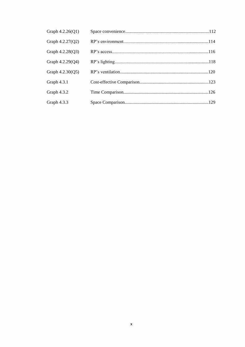
Graph 4.2.26(Q1) Space convenience..........................................................................112
Graph 4.2.27(Q2) RP’s environment...........................................................................114
Graph 4.2.28(Q3) RP’s access.....................................................................................116
Graph 4.2.29(Q4) RP’s lighting...................................................................................118
Graph 4.2.30(Q5) RP’s ventilation..............................................................................120
Graph 4.3.1 Cost-effective Comparison.............................................................123
Graph 4.3.2 Time Comparison...........................................................................126
Graph 4.3.3 Space Comparison..........................................................................129

xi
LIST OF PLATES
Page
Plate 1 Materials and Tools..........................................................................32
Plate 2 Template tracing...............................................................................33
Plate 3 Subtract process................................................................................34
Plate 4 Applying emulsion paint...................................................................35
Plate 5 Applying Polly putty (additive process)...........................................36
Plate 6 Sanding process................................................................................37
Plate 7 Applying glazing putty/duco............................................................38
Plate 8 Applying spray paint.........................................................................39
Plate 9 Detailing...........................................................................................40
Plate 10 Constructing virtual 3D model.........................................................42
Plate 11 Converting 3D file into STL file......................................................43
Plate 12 Transferring STL file........................................................................44
Plate 13 Printing the prototype.......................................................................45
Plate 14 Smoothing the surface......................................................................46
Plate 15 Finishing...........................................................................................47

xii
TERMINOLOGY
3D Printing (3DP) - An additive manufacturing process producing
prototypes.
Conventional
Model Making (CMM) - A process of translating intangible ideas (2D) into
tangible ideas (3D) using hands, hand tools, and
machinery.
Industrial Design (Ide) - A professional service of creating products and
systems that optimize function, value and
appearance for the mutual benefit of user and
manufacturer.
Model - A replica of a design in a 3D form.
Product Design (PD) - A process of creating a new product to be sold by a
business to its customers. Efficient and effective ways
of generating and developing ideas through a process
that leads to new products.
Prototype - A functional model.
Rapid Prototyping (RP) - A rapid process of producing prototypes.

xiii
AMALAN PEMBUATAN MODEL KONVENSIONAL DAN RAPID
PROTOTAIP DALAM PENDIDIKAN REKABENTUK PRODUK DI PUSAT
PENGAJIAN SENI, UNIVERSITI SAINS MALAYSIA. KAJIAN
PERBANDINGAN
ABSTRAK
Penyelidikan ini meneroka proses pembelajaran dalam Pembuatan Model
Konvensional dan Rapid Prototaip seperti yang diamalkan dalam pendidikan
Rekabentuk Produk di Pusat Pengajian Seni , Universiti Sains Malaysia. Parameter
kedua-dua proses Pembuatan Model Konvensional dan Rapid Prototaip dikaji dalam
membuat perbandingan untuk melihat perbezaan dan mencari kelebihan dan
kekurangan didalam kedua-dua proses. Dalam kajian ini, kaedah perbandingan
digunakan dalam memahami parameter yang dikaji iaitu kos , masa dan ruang yang
digunakan didalam kedua-dua proses. Kos, masa dan ruang adalah parameter yang
mempengaruhi pilihan kaedah dalam menghasilkan model atau prototaip oleh
pelajar-pelajar Rekabentuk Produk. Satu Kajian Kes , Kaji Selidik, dan Temuduga
Semi- berstruktur digunakan untuk menerangkan hubungan antara fenomena (CMM
dan RP) dan sebab-musabab (pelajar Rekabentuk Produk) kedua-dua proses
digunakan. Di Pusat Pengajian Seni, Universiti Sains Malaysia, proses pembuatan
model konvensional dan system percetakan 3-Dimensi dikaji sebagai kaedah RP.
Pengkaji menggunakan tiga kumpulan pelajar tahun akhir yang mahir dalam
pembuatan model dan prototaip sebagai sampel untuk soal selidik kajian. Tiga
profesional di dalam pendidikan Reka Bentuk Produk dan Reka Bentuk Perindustrian
ditemuramah untuk memahami lebih mendalam proses Pembuatan Model

xiv
Konvensional dan RP yang diamalkan di dalam pendidikan Rekabentuk Produk.
Terdapat perbezaan di dalam kedua-dua proses berkenaan parameter dikaji. Proses
Pembuatan Model Konvensional didapati lebih kos efektif berbanding RP. Tetapi
proses Pembuatan Model Konvensional adalah satu proses yang berulang-ulang
untuk mendapatkan satu model persembahan yang baik . Dengan ketepatan dan
detail, sistem RP boleh menghasilkan prototaip dalam masa yang lebih pendek
berbanding proses Pembuatan Model Konvensional. Ruang yang minimum untuk RP
mengurangkan penggunaan sistem diakibatkan dari jumlah pelajar yang besar,
manakala Pembuatan Model Konvensional membenarkan pelajar untuk
mengamalkan proses secara bebas sama ada dalam ruang yang disediakan atau ruang
mereka sendiri. Kelebihan dan kekurangan kedua-dua proses adalah seimbang dalam
memberi manfaat kepada pelajar-pelajar Rekabentuk Produk di Pusat Pengajian Seni,
Universiti Sains Malaysia.

xv
THE PRACTICE OF CONVENTIONAL MODEL MAKING AND RAPID
PROTOTYPING IN PRODUCT DESIGN EDUCATION AT THE SCHOOL
OF ARTS, UNIVERSITI SAINS MALAYSIA. A COMPARATIVE STUDY
ABSTRACT
This research explores the learning processes of Conventional Model Making
and Rapid Prototyping as practised in Product Design education at the School of
Arts, Universiti Sains Malaysia. The parameters of both Conventional Model Making
(CMM) and Rapid Prototyping (RP) are studied respectively to compare the
differences and to look for advantages and disadvantages of both processes. In this
research, a comparative method is used to understand the parameters concern; costs,
time, and space. Costs, time, and space are the parameters that affected the choice of
methods in producing a model or a prototype by students of Product Design. A Case
Study, Survey, and Semi-structured Interview are used to explain the relationships
between phenomena (CMM and RP) and causality (Product Design students) of both
processes. In the School of Arts, Universiti Sains Malaysia, CMM process and a 3D
printing system is studied as RP method. The researcher uses three batches of final
year students who are proficient in model making and prototyping as samples for
survey questionnaires. Three professionals in Product Design and Industrial Design
educations are interviewed to understand more in depth on CMM and RP processes
practised in Product Design education. There are differences found in both processes
regarding the parameters concern respectively. CMM process is found more cost-
effective compared to RP. But the CMM process is a time-consumed process with
repetitive process in order to have a good presentation model. With precision and
accuracy the RP system can produce a prototype in a shorter time compared to CMM

xvi
process. Minimal space for RP restricts the use of the system by the large number of
students, whereas the CMM allowed students to practice the process freely either in a
provided space or their own space. The advantages and disadvantages of both
processes are balanced in benefitting the students of Product Design in the School of
Arts, Universiti Sains Malaysia.

1
CHAPTER 1
INTRODUCTION
1.0 Introduction.
In the beginning of this thesis, the researcher will explain about the
background and significant of this study in general. This chapter is divided into
seven sections which will denotes the background of the study (section 1.1), problem
statement (section 1.2), research objectives (section 1.3), research questions (section
1.4, limitations (section 1.5), significant of study (section 1.6), and scope of study
(section 1.7). This will give the reader a glimpse of what this study is all about.
1.1 Background Study
Since Industrial Revolution, Industrial Design brought a new prospect in
manufacturing world (Sotamaa Y, 1992, p. 7). Arguably popularised by Bauhaus in
1919, it became well known as an Industrial Design School. Industrial Design since
taught in the higher institution to produce more designers in this modern world. The
design process is taught in every Design School for future Industrial Designers.
Model making in industrial design is a crucial pre-final/final part in the
design process. It is a process that assists designers to study and analyses form,
detailing, material, and manufacturing process before it goes into the mass-
production. Model making is one of sketching method in the design process but in
three-dimensional forms; a final design as Tim Parsons (2009) put it; ‘Capturing a
rough impression or the complete picture’ (p. 182).
2
Model making is not a new method in design, which had been practised even
before industrial revolution era (Goloboy.J.L, 2008, p. xi). This traditional
techniques or craftsmanship is used to produce a model/prototype by fabricating,
moulding, and forming (Morris, 2009). Fabrication is a process to produce parts in
order to be assembled later by using welding for metal, joints such as dove-tail for
wood, nails, glue and etc. Moulding in the other hand is used to produce one design
piece in one mould such as ceramics, and jewellery. The moulding technique is
widely used in the present day because of the precision and cost-effectiveness in
mass production era. One of the prefer technique is injection moulding (Morris
2009), which melted plastic pellets are injected into a mould. Forming in other
words; ‘to produce something in a particular way or make it have a particular shape’
(Hornby, A.S. 2015, p. 616). Shaping is a process to form or shape solid materials
using hot or cold temperature. This technique was popularly used by blacksmiths in
the past to forge weapons, cooking utensils, and decorative household products
(Morris 2009). With exploration and research done over the years, even wood can be
form according to desired design as popularised by Charles and Eames in the 1950s
by custom-moulding plywood (Hallgrimson. B, 2012, p. 132).
The conventional model making or prototyping process in education (design
school, universities) is almost similar to the industry world. The lack of facilities
such as forming, moulding, and fabrication machinery makes students uses whatever
tools and materials in hands to form their models. Materials such as polystyrene
foam, cardboards, foam board, wood, metal, and Styrofoam are used (Hallgrimson.B,
2012, p. 44). The myriads choices of materials make the model making the process
easier and economical to students in order to make a presentable model. Hand tools
are preferable in making small scale models such as computer mouse or toothbrush.

3
When creating a full-scale model (i.e.; furniture, kiosk) fabrication machines such as
saw mill, drilling, boring, sanding, and welding is used for cutting or jointed parts.
Moulding is also used by undergraduate students in Universiti Sains Malaysia (USM)
but only limited to slip casting. Conventional model making is practice in Product
Design education such as USM or any other design schools to educate students in
developing sensitivity to design surfaces, shape, and form study, detailing analysis
and exploring multiple approaches to achieving the best final presentation
model/product. Manual model making also teaches students to be more creative since
the actual materials are scarce and sometimes expensive to acquire.
Product Design evolves since the Bauhaus era because of one particular
reason; technology. Researchers, scientists, and designers have always found new
materials and methods to manufacture products as fast as possible, sustainable, eco-
friendly, and recyclable. Even though manual model making is still used in industry
or education, a new method was developed in the 1960s; rapid prototyping. This
method soon was developed by University of Texas researcher, Carl Deckard in 1987
from only cutting excess from a block material to building up layer by layer
materials or ‘printing three-dimensional models guided by laser into solid prototypes.
In the recent development in rapid prototyping, the technology became widely used
in industry and even in higher institutions that offer engineering and industrial design
subject. This technology helps students to create more complex parts of their design.
The method helps students to reduce the time of working on their model making
(Hallgrimson, 2012). It involves the use of virtual designs from the computer aided
design (CAD) softwares such as AutoCAD, CATIA, Solid works, Autodesk Inventor
and other CAD software that can create a file which can be read by RP machines
such as an STL (stereolithography) file. Some other three-dimensional surfaces

4
software such as 3D Rhino, 3D Studio Max, and Alias Studio Tools can also be
converted into an STL file. Rapid Prototyping is a subtractive and additive process
that uses materials such as wood blocks, metals, metal powder, polyamide, resin and
much more. A variety of Rapid Prototyping machines are available in the market but
for this particular research, only three-dimensional printing will be focused on.
1.2 Problem Statement
Model making is one of the design processes in Product Design. The purpose
of model making is to study a design in three-dimensional ways where the design
transforms from intangible sketches into a tangible object. The tangible design then
can be feet, touch and analyse to understand the form, ergonomics or materials
suggested on the design. Craftsmanship skills are taught in product design or
industrial design school in order to equip students with essential skills for model
making. Even so, technology has played its part in product design in changing the
way of making a product or changing the way of the design process.
‘Despite the rise of digital tools and rapid prototyping, it has never been more
important for designers to make things with their hands. Comfort with three
dimensions as a sketch and development tool enhances a designer's sensitivity to
form tremendously and helps them understand how products are made in the real
world. If you can build it, you're halfway to knowing how it could be manufactured.
Instead, schools often allow students to jump into 3D CAD before they have a solid
understanding of form and construction.’ (Backett. P, 2011, p. 10). Concerns are
focused on methods of model making taught in schools of product design. As tools
for making a model has changed from conventional to Computer-Aided Design
(CAD), some design schools began to utilise the technology more than the traditional

5
way of making a model. Lacking hand skills or craftsmanship lead to students having
disadvantages in understanding on construction or manufacturing process.
Manufacturing process can be explored by conventional model making as it is fast
and stimulates sensory system (Backett, P. 2011, p. 13)
Conventional model making is an economical way for students to
conceptualise their designs. The myriads of materials choices are also an advantage
to produce a presentable model. The disadvantages of manually making a model are
time and space. To produce a final model student needs to go through a hefty process
which started with plotting their design on a material (e.g.; polystyrene foam),
cutting into basic shape of the plotted details, shaping the material, adding additive
material such as filler or putty and finishing with paints (Hallgrimson, B. 2012, p.
54). Space needed for manual model making varied depending on the size of models
(Hallgrimson, B. 2012, p. 51). If a model uses hand tools from starts to finish they
only require a small space. Space is quite the concern in making a model and
prototyping as the process involves ‘noisy and dirty construction activities’ and for
storing on-going projects (Orr, K., 2008, p. 6). The workshop space is also different
depending on the machines available. Basic machines such as bandsaws, table saws,
disc sander, drill press, lathe and painting booth. For clay making or slip casting
process another space is needed since it uses kiln and blunger (mixer to mix clay and
water to create clay body slip).
The emergence of the RP technology in product design definitely brought a
change to the product design process especially model making process. It is not only
prototyping tools that are used in industries but also have been introduced to product
design schools around the world. The methods use in model making varied among

6
product design school. Some integrate more on technologies such as RP and some
focus on the conventional way of model making. This matter raised some questions
in the product design educations such as; which process can benefit product design
education? Will conventional model making become obsolete? Is one process
dominant than the other? This study will give an insight on both methods in
education and to find the advantages and disadvantages of both methods practised by
BFA students in Product Design education in University Sains Malaysia.
The problems found in the literature reviewed are as follows:-
1. Lack of comparative studies done on the practised of conventional model
making and rapid prototyping process in Product Design education.
2. A lot of studies were made in favour of rapid prototyping compared to
conventional model making.
3. Previous studies discuss more on the benefits of rapid prototyping.
1.3 Research Objectives
The objectives of this research are as follows:-
1. To look into the Conventional Model Making (CMM) and Rapid Prototyping
(RP) practised in Product Design at Universiti Sains Malaysia and learning
process.
2. To identify the costs, time, and space that affects the Conventional Model
Making and Rapid Prototyping process in Product Design.
3. To understand the variables of both processes in complementing the study of
Product Design in Universiti Sains Malaysia.

7
1.4 Research Questions.
1. What methods are used in producing model and prototype in Product Design
education?
2. What parameters affect the Conventional Model Making and Rapid
Prototyping process in Product Design?
3. Is one of the processes more beneficial and more educational than the
other for Product Design education in the School of Arts, Universiti Sains
Malaysia?
1.5 Limitations
1. Only 3D printing system available for Rapid Prototyping process’
observation.
2. Small sample.
1.6 Significant of Study
This research is done to understand the parameters that affected model
making/prototyping process in Product Design education at the School of Arts,
Universiti Sains Malaysia. In recent years, there are changes in making a model or
prototype in Product Design education worldwide. The method of producing a model
evolved technology-wise. The transitions from conventional model making to Rapid
Prototyping process can be seen in many Higher Institutions that teach Product
Design. The research is to compare both methods in order to seek differences and to
find the advantages and disadvantages of both methods as practised in Product
Design at the School of Arts, Universiti Sains Malaysia. The outcome of this
research can be useful to Product Design education in the School of Arts, Universiti
Sains Malaysia.

8
1.7 Scope of Study
1. Conventional Model Making and Rapid Prototyping processes practised by
Product Design students in the School of Arts, Universiti Sains Malaysia.
2. Only final year students of BFA Product Design in Universiti Sains Malaysia
will be used as a sample in this research.

9
1.8 Research Framework
Figure 1.8: Research Framework
The Practise of Conventional Model Making and Rapid Prototyping in Product
Design Education at The School of the Arts, Universiti Sains Malaysia. A
Comparative Study.
Literature Review
Product Design study.
Conventional model making issues.
Rapid Prototyping Issues.
Framing the issues.
Framing the methodology.
Framing the theory.
Problem Statement
Lack of comparative studies done on the practised of conventional model making and rapid
prototyping process in Product Design education.
Insufficient sources on conventional Model making and rapid prototyping in Product Design
Education.
1. To look at Conventional Model Making and Rapid Prototyping (3D Printing) learning process.
2. To identify the costs, time, and space of Conventional Model Making and Rapid Prototyping (3D
Printing) process in Product Design.
3. To understand the variables of both processes in complementing the study of Product Design in
Universiti Sains Malaysia.
Objectives

10
1.9 Summary
This research is conducted in order to compare two methods of model making
in Product Design education. The researcher will study the processes of conventional
model making and rapid prototyping in order to identify the advantages and
disadvantages of both processes. In the processes; space, time and costs will be
studied upon to identify the differences between manual model making and rapid
prototyping. The outcome of this research will be to compare the data on
Conventional Model Making and Rapid Prototyping (3D Printing) processes and
identify benefits in complementing the Product Design study in USM. Literature for
issues and problems for this research will be elaborate in the second chapter of the
thesis.
11
CHAPTER 2
LITERATURE REVIEW
2.0 Introduction.
The first phase of this study, the researcher conducts literature reviews and
found writing by Ziba’s Industrial Design Director, Paul Backett. In this article,
Backett (2011) emphasis on the lack of skills in manual model making by industrial
design graduate caused by technology evolution that creates graduates dependable
only by technology, not raw skills. The researcher found out that both processes of
model making are quite the debate around Product Design education system.
Professionals like Backett disagrees with too much technology i.e.; 3D printing, 3D
software to be implemented in industrial design schools which will create the lack of
understanding in design forms. In his claim, the net generations conclusively utilise
technology instead of the conventional method of model making (2011). In a study
by Irene J. Petrick & Timothy W. Simpson (2013), they put it in the more drastic
claim; technology such as 3D printing posts a disruptive effect on conventional
method. In other studies (Lantada, A.D., et al., 2007; Berman, B., 2012) disputes the
claims as they indicate the advent of rapid prototyping technology, CAD and CAID
reduce the model making process in terms of time and costs. Whereas, Cheshire
D.G., et al. (2001) suggests in their study on combining both methods as converging
factors in achieving better design results.
With different views on model making process, the researcher found a gap in
the previous research indicating a lack of research conducted in comparing the

12
practice of conventional model making and rapid prototyping process in Product
Design education.
2.1 Classifications of Physical Model.
A model and a prototype are both physical models which are tangible ideas
derived from the iterative process of two-dimensional sketching. As defined by
Hallgrimson (2012), physical models are used to ‘described a preliminary three-
dimensional representation of a product, service or system.’ (p.6). The physical
models work as a communication tool representing the ideas of the designers in
three-dimensional forms. The purpose of physical models is not for manufacturing,
but it works as design tools for future ideas and will encourage more exploration on
the design itself. The physical models are crucial in design as it is not just a visual
representation of a design such as sketching but the tangibility makes it explore-able.
(Dunn N., 2010). Broek J.J et al. (2000) point out the physical model's’ functions are
used to ‘answer designers’ questions’ (p. 155). Parsons T. (2009) states that the
designers need to consider the purpose of making the models, things to analyse and
effect to produce the models as to ‘increased closeness to the designer’s imagination
(p. 182). It is a part of the problem-solving process and designers need a tangible
idea to ‘intrigues the imagination and allows for a constant stream of sculpted ideas
to be evaluated’. (Bramston D., 2010, p. 42)
Physical models are tools to analyse ergonomics, forms, aesthetics,
functionality depend on the levels or categories they are in. Tim Parsons (2009)
categorised physical models into three levels; (1) maquette, (2) model, and (3)
prototype (p.182). The different levels are made based on the speed and detail on

13
producing the physical models. Maquette and model functions are to study forms and
aesthetics, whereas a prototype is used as a tool to study ergonomics, materials, and
functionality of an idea. Isa, S.S., & Liem, A. (2014) classified physical models
into four categories (see figure 2.0); (1) soft model, (2) hard model, (3) presentation
model, and (4) prototype (p.3), as explained in Figure 2.0.
Figure 2.0.1: Classifications of Physical Models by Isa, S.S., & Liem, A., 2014, p.
3.
Based on the classifications as shown in Figure 2.0, there are two types of the
physical model focused in this research; Presentation Model and Rapid Prototyping
(advance method of prototyping). The researcher looks into the process of making
using both methods that have been assisting students in making a tangible idea. Some
issues from previous studies are break down into two main issues as analysed in next
point.

14
Figure 2.0.2: Types of soft models.
(Source: Researcher’s Source)
Figure 2.0.3: Type of Presentation Model.
(Source: Researcher’s Source)

15
Figure 2.0.4: Types of Prototype
(Source: http://www.core77.com/posts/36551/7-Tips-for-Nailing-that-Industrial-
Design-Job-Interview)

16
2.2 Conventional Model Making (CMM) Issues.
For producing CMM, designers take into considerations on time, speed, and
costs’ factors involving the whole process. Materials play a big factor in determining
the speed and costs of CMM. According to Dunn (2010), materials selection for the
model making are determined by three key factors; ‘the speed of production, the
stage of the design process and the intended purpose or function of the model.’ (p.
30)
Looking at time-constraint parameter in previous studies (Osaid H.M., et al.
2015; Isa, S.S., & Liem, A., 2014), CMM process requires skilled labours, different
machinery utilisation, and manipulation of different materials that prolong the
process’ duration. As the physical model is a representation of the final design ideas,
suitable materials are needed in order to replicate. Model maker with less experience
and skills will delay the process of model making. Kristian Orr (2008) stated
‘availability of time’ as one of the challenges in making models and prototype in
architecture education environment. As the model making process is the most crucial
part of the design process, longer times are needed to produce a model. Broek, J.J., et
al. (2000) agrees on this issue as they stated in their study that producing a model in
a shorter time will benefit the problem-solving process. Kolko, Jon (2005) denotes
that changes from the traditional method to the new method are imminent regarding
production cycle time to market and increasing in speed of production is inevitable.
This is a proof that CMM is a time-consuming process practised either in industries
or education levels. A design project given to designers or students is time-
constraint. Dateline are given in order for designers to plan their process of design
thinking, problem-solving and analysis of the given project. Making a model or a

17
prototype is a crucial process in representing the solution of the design. Completing
the model or prototype in time allow manufacturing and marketing of the product be
made.
Costs are discussed in previous research extensively regarding model making
and prototyping. Materials using is one aspect that affects cost especially in ‘an era
of tightened university budgets’ (Orr, K., 2008, p. 6). Hafiz Muhammad Osaid et al.,
(2015) listed materials and tools (machinery) as part of cost issue in CMM.
Designers have to choose the materials that will not slow down the process or delay
the production process. In an educational environment, choices of materials are vast
as the models are an only tangible representation of their intended design. The key
factor for students is to practically choose materials that abundantly found whether
discarded materials or cheap materials such as Styrofoam, box, PVC and etc. Parsons
T. (2009) indicates by using inexpensive materials, ‘enables designers to work
without a restricting sense of preciousness’ (p. 184). Manipulating ready-made object
and re-shaping it into the desired shape can reduce the cost of CMM.
The process of CMM is divided into two; subtractive and additive. This
process consists of shaping raw materials into a form following a design and adding
materials such as putty and hardener if needed in order to harden the raw materials or
fixing any abrasion on the product’s surface. The material in the definition is a
substance or substances from which something else is or can be made; a thing or
things with which something is done (Hornby, 1995). Materials used for CMM are
varied depending on the size and needs of the design. In CMM using either recycle
materials or substitute materials is easier to work with and can be found easily in
comparison with manufacturing materials.

18
‘Combining materials in order to emphasize their contrasting qualities and
make best use of them requires considerable experimentation, and model makers
should be encouraged to explore the use of novel, ‘found’ materials as well as to
recycle packaging and other everyday objects in the search for appropriate
materials.’ (Dunn N., 2010, p. 31)
In Product Design discarded materials with other materials such as
polystyrene foam, wood (jelutong, pine, and plywood), polyvinyl chloride (PVC) and
etc. are utilised and sometimes combine to create 3D visual of different materials.
Using recycle materials reduce the costs for model making especially when it comes
to the educational environment. Size and scale also play a crucial part in determining
types of materials that the designer or modeller for the model making process. ‘It is
typically more cost- and time-efficient to substitute softer materials in place of
production materials’ (Hallgrimson B., 2012) A model is not a final product
(production), it is an imitation to what it should look like, feel, and functions. Softer
materials give an advantage to designers to sculpt the model quickly and efficiently
in acquiring the form of the design. ‘Preliminary models, often made of polymer
foam, plaster, wood or clay, capture the form of the product; later models show the
form, colour, texture, mechanisms and weight.’ (Ashby M., & Johnson K., 2002, p.
43)
Affecting the CMM process includes space and environment which depends
on materials, and tools available. According to Hallgrimson (2012, p. 51), some
materials requires ‘small, and simple workshop, whereas others require substantial
model making facilities’. In some design industries, to be able to do sketch-model or
model making, designers use their provided workshop. Space required for model

19
making or prototyping is crucial here. Kristen Orr (2008) argued about the
availability of space, as producing a model in time in an educational environment is
hard to achieve as he provided space is insufficient to accommodate the large
numbers of students. Some of the researchers mention on issues regarding space use
in the CMM but lacking emphasis on the matter.
Figure 2.2: Example of Materials used in CMM.
(Source: Researcher’s Source)

20
2.3 Rapid Prototyping (RP) Issues.
Prototyping is a process of producing functional design model or prototype
before undergoing manufacturing or production process. Nowadays, the process has
become better because of new technology in prototyping; rapid prototyping. As it
sounds, this process is faster than conventional model making and produce
complicated details that cannot be achieved by conventional means.
Rapid prototyping (RP) is vastly used in manufacturing industries worldwide
and becoming more prevalent as it helps designers and engineers to ‘visualise design
concept, ergonomics evaluation, master patterns, functionalities’ evaluation, and
customised products’ (Stampfl J., Liska R., 2005, p. 1253). Rapid prototyping
process can produce detailed parts as it forms the parts by ‘depositing contoured
material’ on x and y-axis. The third axis; z-axis creates stepping shape as this third
dimension axis depends on the thickness of the deposited materials (Pandey, 2010).
RP allows the designer to prototype more frequent to analyse the functionality of the
design, problems and finding solutions for their design. Realising an idea from two-
dimensional drawing to three-dimensional object minimised mistakes ‘and product
development costs and lead times substantially reduced’ (Pham, D.T & Gault, R.S.,
1998, p. 1258). Several studies (Pham, D.T. & Gault, R.S., 1998; Diegel, O. et al.,
2006; C. Weller, et al. 2015) agrees on the factors such as time and costs can be
reduced in prototyping compared to CMM. The traditional process of design and
prototyping are minimalised using RP as a tool for producing more details, and
analytical prototype. RP also allows designers to experience several iterations of
their design and helps in encountering issues in more details. O. Diegel, et al., (2006)
explains that ‘the process of prototyping any ideas as they come along means that

21
you often have to look at parts of the manufacturing, and even in marketing
processes, even when you are still at the fuzzy front-end concept development stage’
(p. 357). But in this situation, where the designers can easily prototype several
iterations of design using RP will cost more than CMM since materials for RP are
not cost-effective. Looking at too many details & functions also lead to a time-
consuming process. Iteration of ideas by RP means also depends on the number of
RP system available. As in Product Design education, a model or prototype mostly
functions as presentation design object. Manufacturing aspect is not a priority in
model making or prototyping practised in Product Design education.
Materials used in rapid prototyping are varied from wood, ABS (acrylonitrile
butadiene styrene), nylon, metal, thermoplastics and etc. Every RP machine has
different materials that it can produce. Hallgrimson divides materials for RP systems
into three; ‘Photo-curable liquids (photopolymers), solid powders or extruded
plastic’. Hallgrimson (2012) emphasis on the importance of materials selection in RP
process as it determines the level of quality that it produces. The materials chosen
determine the ‘cost, strength, surface quality and colours’ (p. 67). O. Diegel et al.
(2006) argued that ‘Traditional project management tends to focus on what is often
called the ‘holy triangle’ of project management; cost, time, quality’ (p. 350). With
RP, costs and time can be reduced to achieve the market goal on time. RP makes it
possible to build intricate prototypes and working prototypes allowing testing and
predominantly reduce time than conventional methods. This method allows designers
to analyse forms, ergonomics and other design questions in a shorter time. Berman
B. (2012) indicates ‘3D printer can produce simple objects, such as a gear, in less
than 1 hour’ (p. 155). Berman states the two important aspects that affect the RP
process are cost and materials (p. 156). In spite of the advantages, some drawbacks

22
of RP made mention by Berman B., (2012) such as limited materials, limited surface
finish, the high cost of materials and expensive RP system (p. 161). Although the RP
process benefits the prototyping process in reducing the time, the drawbacks of RP
process can affect Product Design students pragmatically.
Figure 2.3: Example of Rapid Prototyping (3DP) Materials.
(Source: Retrieved from https://3dprint.com/42417/3d-printing-material-strengths/)

23
2.4 Framing the issues.
Most of the researcher emphasis on the advantages of using RP as
prototyping method. There were less information or research done in CMM process.
Few researchers studies on the practice of model making and prototyping process in
Product Design education. Previous studies discuss more on the transition from
conventional process to utilise the latest technology and most focusing on processes
that were practised in the industries. This can be seen clearly from most of the
literature found while doing this research. Research gap is found concerning model
making and prototyping process practised in the educational level and space
parameter to expand more in this study.
Nevertheless, the researcher extracts some crucial evidence from previous
studies to support this research. One of the crucial evidence found is the criterion that
affects the CMM and RP process such as costs, time, materials, and space. As
materials are related to costs, the researcher will look into costs and time. Space is
one of the parameters that the researcher considers important to expand because, in
this research context, facilities such as workshops are built to accommodate a
minimum number of students.

24
2.5 Framing the Methodology
Having examined from several literature sources, the researcher discovers
that case study, interviews, surveys and direct observations were used by some
researchers as methods in their studies. Among them, there are few who conducted
mix method in their research.
O. Diegel et al., (2006) uses a case study to compare RP and traditional
process of prototyping in educational engineering. They conducted a project given to
students to understand the difference in the component used, process, design time,
making time and cost that affects both processes. The same as Orr, K., (2008), who
also conducted a case study which using an architectural project given to students in
understanding how architectural students conduct their projects and what parameters
affect the process and the effect on students’ educational process. Both case studies
conducted starts from the beginning stage of design process until prototyping stage.
In this research context, the researcher will only focus on the model making or
prototyping process per se. Sketching, drawing, detail/technical drawing, or mock-up
making are disregards in this research.
Documents’ analysis was used in identifying parameters that affect
prototyping and RP process by D.T. Pham and R.S. Gault (1998). Whereas Weller
C., et al. (2015) conducted analysis on market structure models to discuss economics
effects on Additive Manufacturing or RP. Vayre B. et al. (2012) suggests their own
methodology in the process of designing by utilising RP. This method is used by
conducting a simple project to look into the design process in order to approve or
disprove their hypothesis. Validation is made by virtual manufacturing their design
(p. 636).
Top Related