


Languages
Pages
Legal


The next-generation space solar observatory:
The SOLAR-C Mission�
K. Watanabe & H. Hara ISAS/JAXA & NAOJ
SOLAR-C WG 2015 Feb 27�
ISSI#Coronal#Rain#�
Basic#Problems##in#Helio(Physics�1.#Origin#of#large8scale#
explosion�
2.#Hea=ng#of#chromosphere#and#corona,#
Solar#wind#accelera=on�
3.#Magne=c#cycle#
Planned##satellite##Solar#observatory#prepared#by#JAXA##SOLAR8C#W.G.�
First#determines#3D#magne=c#structures#from#unprecedented#observa=ons#for##elucida=ng#basic#problems#in#Helio8Phys.##
Keywords:##8#Chromospheric#B#measurements##8#0.1”#–#0.3”#spa=al#resolu=on##8#�1s#high8cadence#observa=ons##8#high#resolu=on#spectroscopy�
SOLAR-C�
(0.1”#=#70#km)�
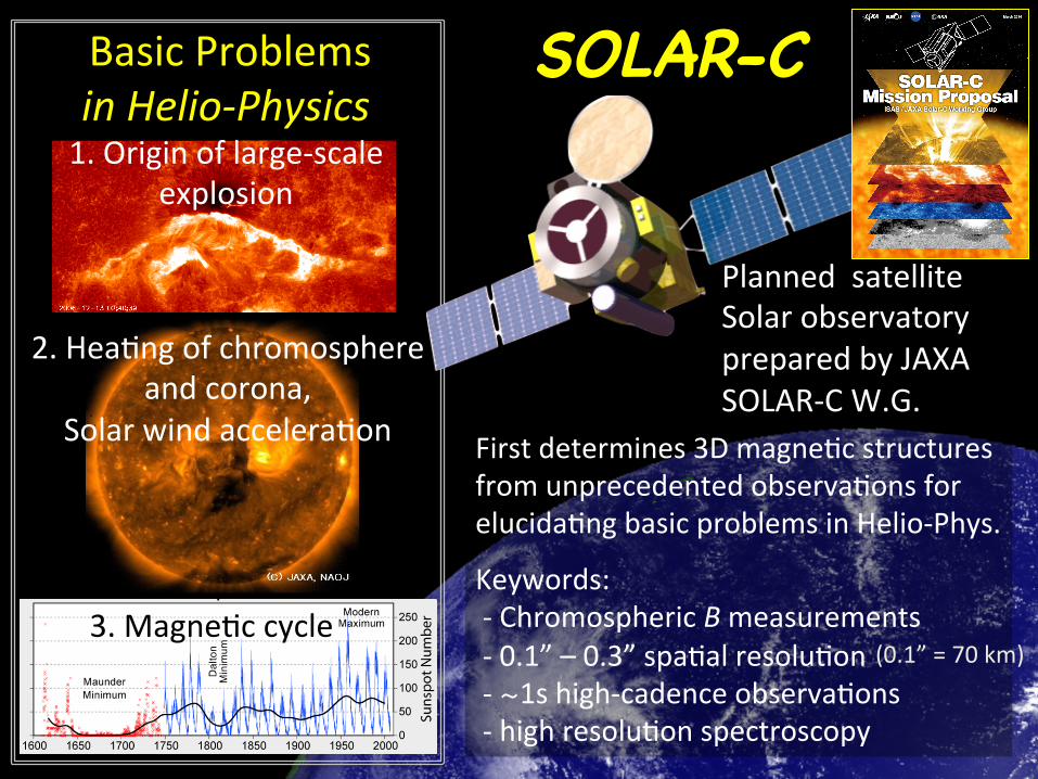
Science#Objec=ves#Observations of All from photosphere to corona seamlessly
as a system�
SOLAR8C#FOV)&180#“#×&140”�
SOLAR8C#FOV)&280#“#×&280”�
SOLAR8C#FOV)&400#“#×&400”�• Physical#origin#of#explosions#that#
drive#short8=me#geo8space#variability#
• Mechanisms#responsible#for##– hea=ng#and#dynamics#of#chromosphere#&#corona#
– accelera=on#of#solar#wind#• Fundamental#physical#processes#
– Magne=c#reconnec=on,#MHD#waves,#shocks,#etc.#
• Fine8scale#magne=sm#and#associated#solar#spectral#irradiance#
SOLAR8C#will#determine�

EPIC: European Participation in Solar-C 4 MISSION CONFIGURATION AND PROFILE
SUVIT/IUSUVIT/UBIS
SUVIT/SPSUVIT/FG
HCI
Startracker
UltrafineSun Sensor
+Z
+Y
+X
Telemetry Antenna
SUVIT/TA
EUVST
Telescope Door
+Z
+Y
+X
Heat Dump WindowStartracker
Telemetry AntennaSolar Array Panel
Apogee Kick EngineThrusters
SUVIT/TAHCI
Optical Bench Unit
Telemetry AntennaBus Module
Inertial Reference Unit(Gyros, part of Bus Module)
Figure 26: Solar-C Spacecraft; source: NAOJ. The scientific payload also includes the Irradiance Monitor (IM).
vide the downlink of science data to ground via X-bandcommunication channels (see Section 4.5). The Iner-tia Reference Unit (IRU), not visible in Figure 26) willbe established by a fibre-optic gyro system with low-est possible drift rates. The startrackers and the IRUwill have considerable heritage from and achieve per-formance levels as those in Alphasat, Sentinel-2 andEDRS-C.
Instruments and spacecraft structures that are essen-tial for stability and accuracy, are equipped with heatersto provide a stable thermal environment. In addition, in-struments will have emergency heaters to keep them in asafe state in case of malfunctions of the bus system. Theheating power requirements are the result of a detailedthermal analysis which will be carried out as part of thedesign phase.
Two solar array panels are deployed from the twosides of the spacecraft body and are designed to generateabout 5 000 Watt of electrical power. A possible reduc-tion of the panel size or of the number of solar cells willbe based on the more accurately determined power re-quirements available after the definition phase. The sizeof the spacecraft body (telescopes and bus module) isroughly 3.7 ⇥ 3.2 ⇥ 7.1m3, excluding the solar arrays.This size fits in the fairing envelope of the H-IIA 4Srocket. The estimate for the total mass is about 4 met-ric tons, which consists of 2.3 ton dry mass and 1.7 tonpropellant, which requires efforts on reduction for a H-IIA launch, but the mass constraint may be relaxed withthe new H-III rocket (first flight expected in 2020).
The model specification of the spacecraft system issummarised in Table 6.
38
SOLAR-C Spacecraft�
Hinode�
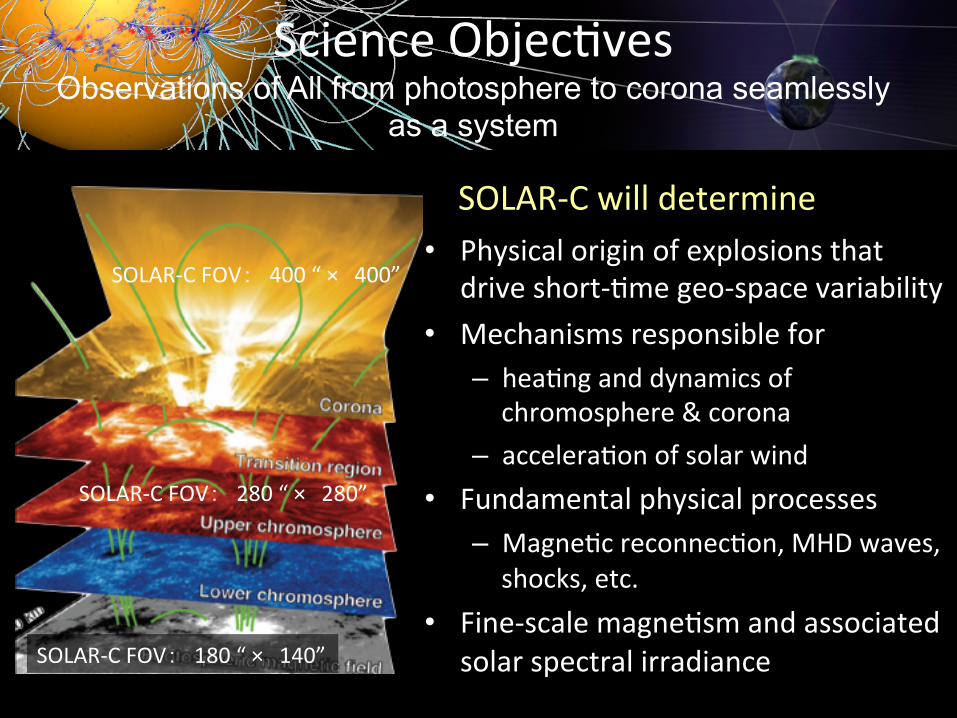
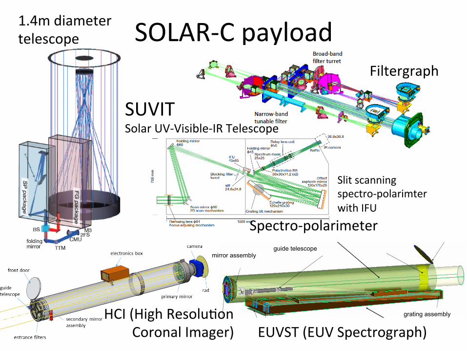
SUVIT#TA#1.4#m#diameter#telescope�
EUVST#(EUV#Spectroscopic#Telescope)�
HCI#(High#Resolu=on#########Coronal#Imager)�
SUVIT:#Solar#UV8Visible8IR#Telescope#
50cm#dia.#telescope�
Chromospheric#magne=c#fields#measurements�
EPIC: European Participation in Solar-C 3 PROPOSED SCIENTIFIC INSTRUMENTS
Figure 24: The opto-mechanical layout of HCI. The layout resembles that of the EUV imagers TRACE, SDO/AIA and Hi-C.
10 Hz bandwidth cutoff and will allow smooth operationof the image motion compensation system.
In terms of resources, the instrument occupies avolume of 430 ⇥ 70 ⇥ 40 cm3, has a mass of 155 kg(including 15 % margin) and requires 68 W power (ofwhich 24 W for operational heaters).
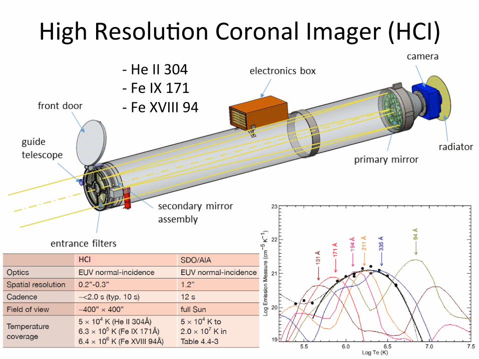
3.4 High Resolution Coronal Imager (HCI)
The HCI is a normal-incidence EUV telescope con-sisting of primary and secondary mirrors in Ritchey-Chretien configuration. It will perform high-resolutionimaging in the EUV pass-bands described in Sec-tion 2.4: 30.4 nm containing the He II resonance line asdiagnostic of the transition region, 17.1 nm containinglines of Fe IX and Fe X showing 1 MK coronal struc-tures at high contrast, and 9.4 nm containing Fe XVIIIwith emission in very hot outburst features.
Table 5 summarises key design features of HCI.The primary and secondary mirrors are both dividedinto three sectors, with each sector coated with differentmulti-layer coatings for high reflectance in the pertinentpassband. The sectors have different areas to accommo-date expected count rates (17.1 nm 33%, 30.4 nm 17%,9.4 nm 50%, respectively).
The primary mirror will have a clear aperture of32 cm diameter. Wavelength selection will be done witha filter wheel as in SDO/AIA.
The optics will give an effective focal length of20 m. Combined with a 10µm pixel back-thinned CCD(4k⇥4k format) this gives 0.100/pixel sampling.
The secondary mirror will have an active mount thatis actuated to remove instrument pointing errors and fo-cus the system, as in TRACE and SDO/AIA. As in these
instruments, HCI will have a guide telescope for Sun-tracking to feed the image stabiliser. This system willincorporate spacecraft pointing information to achievethe required pointing accuracy and stability.
Entrance filters will reject visible light. An aper-ture door protects them during launch, as in TRACE andSDO/AIA. A mechanical shutter near the focal planecontrols the exposure time. Typical exposure times (asfor the comparable channels of SDO/AIA) will rangefrom 0.1 s for flares to 100 s for dark quiet-Sun targets.
The analog output from the single CCD will be con-verted into 14 bits. In standard observing, the readoutarea will cover only one quarter of the full FOV (2k⇥2kpixels or 20500⇥20500) at an exposure cadence of 10 s.The planned data rates for normal-cadence observationsare 5.9 Mbps (raw), 2.9 Mbps (lossless) and 1.3 Mbps(lossy). In lossless compression each pixel value corre-sponds to 7 bits; in lossy compression only 3 bits. In fastsmall-area sampling 1024 ⇥ 1024 pixels (10000⇥10000)readout can reach 1 s cadence with lossy compression.
HCI will use large heritage from the comparableEUV imagers on-board TRACE and SDO/AIA. How-ever, as the instrument will have 5–6 times better an-gular resolution, the following issues will be assessedduring the definition phase:– mirror micro-roughness, i.e., optimising multi-layer
reflectance and minimising wide-angle scattering;.– effect of multi-layer coatings on effective area after
masking;– stabilisation at twice the resolution of IRIS;– vibration from moving elements (as the filter wheel);– effect of hits by energetic particles.
36
!"##$#%&''(!)*+
,(*('-$.((*(-,#$/"-'
01"2(%,(*('-$.(
2(3*(-,$#%.*&,(
3#$/,2$$#!"#"$%&'"()*+,
-'"%,.&/.0'1()*+,
0#&,"/0%&''(!)*+
2(,(-,$#%&''(!)*"('
SOLAR8C#payload�1.4m#diameter#telescope�
SUVIT#Solar#UV8Visible8IR#Telescope�
Spectro8polarimeter�
Filtergraph�
EUVST#(EUV#Spectrograph)�HCI#(High#Resolu=on##########Coronal#Imager)�
Slit#scanning##spectro8polarimter##with#IFU�
1.22*k/D
0.01 0.10 1.00 10.00 100.00 1000.00Wavelength (nm)
0.1
1.0
10.0Sp
atia
l Res
olut
ion
(arc
sec)
140 cm
50 cm
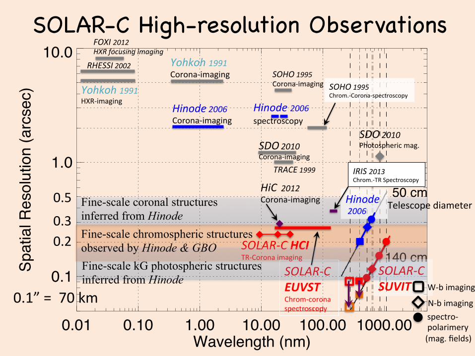
SOLAR-C High-resolution Observations�
SDO#2010##Corona8imaging�
Yohkoh#1991#Corona8imaging�
Hinode#2006#Corona8imaging�
IRIS#2013#Chrom.8TR#Spectroscopy�
Yohkoh#1991#HXR8imaging�
TRACE#1999#
HiC##2012#Corona8imaging�
Hinode#2006##spectroscopy�
Hinode##2006#
SOLAR(C#SUVIT&
SOHO#1995#Corona8imaging� SOHO#1995#
Chrom.8Corona8spectroscopy�
SOLAR(C#EUVST&Chrom8corona#spectroscopy�
SOLAR(C#HCI&TR8Corona#imaging�
0.2�
0.3�
0.5�
RHESSI#2002#
FOXI#2012#HXR#focusing#imaging#
Telescope#diameter�
0.1”#=##70#km�&spectro8####polarimery###(mag.#fields)�
W8b#imaging�
N8b#imaging�
SDO#2010##Photospheric#mag.�
Fine-scale coronal structures inferred from Hinode�Fine-scale chromospheric structures observed by Hinode & GBO Fine-scale kG photospheric structures inferred from Hinode�

1.22*k/D
0.01 0.10 1.00 10.00 100.00 1000.00Wavelength (nm)
0.1
1.0
10.0Sp
atia
l Res
olut
ion
(arc
sec)
140 cm
50 cm
SOLAR-C High-resolution Observations�
SDO#2010##Corona8imaging�
Yohkoh#1991#Corona8imaging�
Hinode#2006#Corona8imaging�
IRIS#2013#Chrom.8TR#Spectroscopy�
Yohkoh#1991#HXR8imaging�
TRACE#1999#
HiC##2012#Corona8imaging�
Hinode#2006##spectroscopy�
Hinode##2006#
SOLAR(C#SUVIT&
SOHO#1995#Corona8imaging� SOHO#1995#
Chrom.8Corona8spectroscopy�
SOLAR(C#EUVST&Chrom8corona#spectroscopy�
SOLAR(C#HCI&TR8Corona#imaging�
0.2�
0.3�
0.5�
RHESSI#2002#
FOXI#2012#HXR#focusing#imaging#
Telescope#diameter�
0.1”#=##70#km�&spectro8####polarimery###(mag.#fields)�
W8b#imaging�
N8b#imaging�
SDO#2010##Photospheric#mag.�
Fine-scale coronal structures inferred from Hinode�Fine-scale chromospheric structures observed by Hinode & GBO Fine-scale kG photospheric structures inferred from Hinode�

EUVST#280”#x#280”�
HCI#410”#x#410”�
SUVIT#184”#x#184”#
�
SOLAR8C:#Field#of#View#(FOV)�
SUVIT�
FG� SP�
WB� NB�
Hi8#Res.�
###�
Wide#FOV�
184”x184”�184”x143”�
61”x61”� 90”x90”�
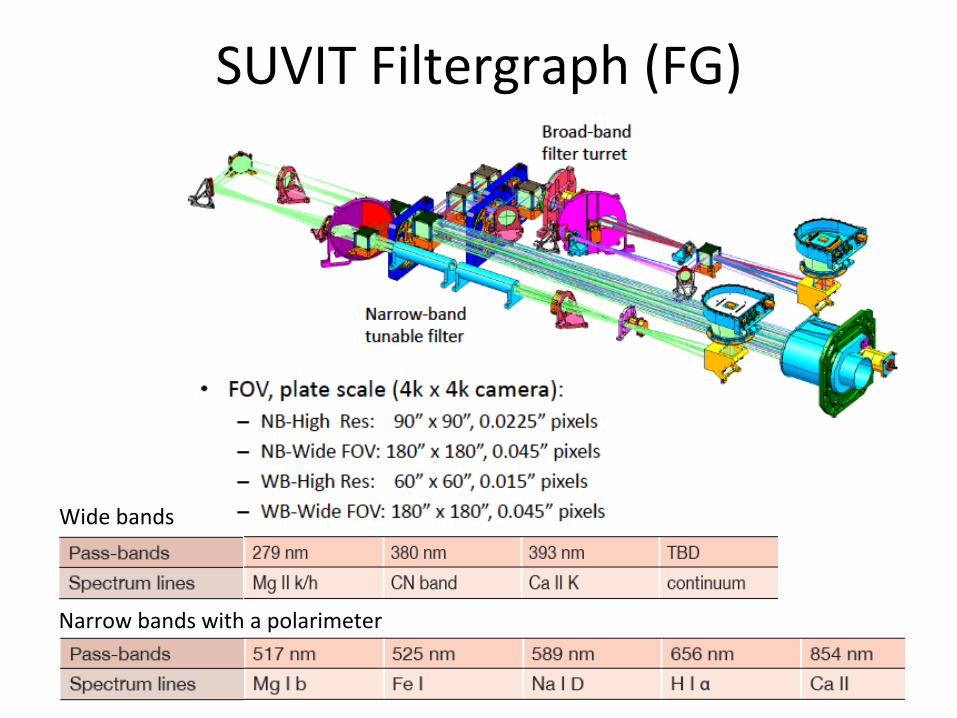
Narrow#bands#with#a#polarimeter�
Wide#bands�
SUVIT#Filtergraph#(FG)�
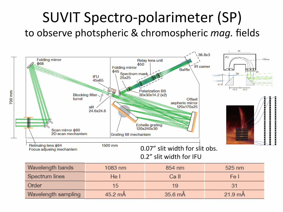
SUVIT#Spectro8polarimeter#(SP)#to#observe#photspheric#&#chromospheric#mag.#fields�
0.07”#slit#width#for#slit#obs.#0.2”#slit#width#for#IFU�
Solar-C EUVS
!"##$#%&''(!)*+
,(*('-$.((*(-,#$/"-'
01"2(%,(*('-$.(
2(3*(-,$#%.*&,(
3#$/,2$$#!"#"$%&'"()*+,
-'"%,.&/.0'1()*+,
0#&,"/0%&''(!)*+
2(,(-,$#%&''(!)*"('
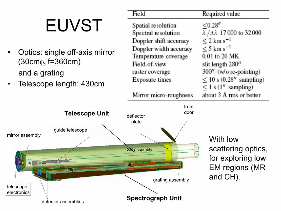
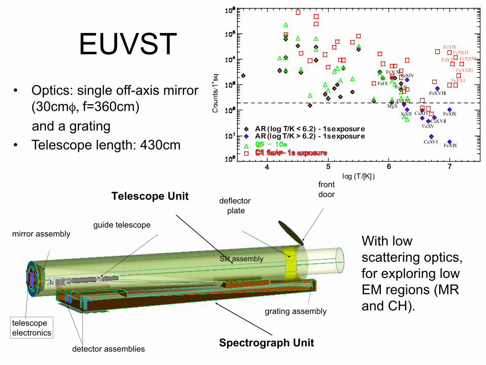
EUVST�
Slit assembly�
• Optics: single off-axis mirror (30cmφ, f=360cm)
and a grating • Telescope length: 430cm �
With low scattering optics, for exploring low EM regions (MR and CH).�
!"##$#%&''(!)*+
,(*('-$.((*(-,#$/"-'
01"2(%,(*('-$.(
2(3*(-,$#%.*&,(
3#$/,2$$#!"#"$%&'"()*+,
-'"%,.&/.0'1()*+,
0#&,"/0%&''(!)*+
2(,(-,$#%&''(!)*"('
EUVST�• Optics: single off-axis mirror
(30cmφ, f=360cm) and a grating • Telescope length: 430cm �
AR (log T/K < 6.2) - 1s exposureAR (log T/K > 6.2) - 1s exposure
log (T/[K])4 5 6 7
FeIX
FeX/XI
MgX
FeXII
FeXIII
FeXIV
SiXII CaXIV
CaXV
CaXVI
CaXVII
FeXVIII
FeXIX
FeXIX
FeXIX
FeXX
FeXXIII
FeXXIIFeXXIV
FeXXI
Slit assembly�
With low scattering optics, for exploring low EM regions (MR and CH).�
EPIC: European Participation in Solar-C 3 PROPOSED SCIENTIFIC INSTRUMENTS
Figure 24: The opto-mechanical layout of HCI. The layout resembles that of the EUV imagers TRACE, SDO/AIA and Hi-C.
10 Hz bandwidth cutoff and will allow smooth operationof the image motion compensation system.
In terms of resources, the instrument occupies avolume of 430 ⇥ 70 ⇥ 40 cm3, has a mass of 155 kg(including 15 % margin) and requires 68 W power (ofwhich 24 W for operational heaters).
3.4 High Resolution Coronal Imager (HCI)
The HCI is a normal-incidence EUV telescope con-sisting of primary and secondary mirrors in Ritchey-Chretien configuration. It will perform high-resolutionimaging in the EUV pass-bands described in Sec-tion 2.4: 30.4 nm containing the He II resonance line asdiagnostic of the transition region, 17.1 nm containinglines of Fe IX and Fe X showing 1 MK coronal struc-tures at high contrast, and 9.4 nm containing Fe XVIIIwith emission in very hot outburst features.
Table 5 summarises key design features of HCI.The primary and secondary mirrors are both dividedinto three sectors, with each sector coated with differentmulti-layer coatings for high reflectance in the pertinentpassband. The sectors have different areas to accommo-date expected count rates (17.1 nm 33%, 30.4 nm 17%,9.4 nm 50%, respectively).
The primary mirror will have a clear aperture of32 cm diameter. Wavelength selection will be done witha filter wheel as in SDO/AIA.
The optics will give an effective focal length of20 m. Combined with a 10µm pixel back-thinned CCD(4k⇥4k format) this gives 0.100/pixel sampling.
The secondary mirror will have an active mount thatis actuated to remove instrument pointing errors and fo-cus the system, as in TRACE and SDO/AIA. As in these
instruments, HCI will have a guide telescope for Sun-tracking to feed the image stabiliser. This system willincorporate spacecraft pointing information to achievethe required pointing accuracy and stability.
Entrance filters will reject visible light. An aper-ture door protects them during launch, as in TRACE andSDO/AIA. A mechanical shutter near the focal planecontrols the exposure time. Typical exposure times (asfor the comparable channels of SDO/AIA) will rangefrom 0.1 s for flares to 100 s for dark quiet-Sun targets.
The analog output from the single CCD will be con-verted into 14 bits. In standard observing, the readoutarea will cover only one quarter of the full FOV (2k⇥2kpixels or 20500⇥20500) at an exposure cadence of 10 s.The planned data rates for normal-cadence observationsare 5.9 Mbps (raw), 2.9 Mbps (lossless) and 1.3 Mbps(lossy). In lossless compression each pixel value corre-sponds to 7 bits; in lossy compression only 3 bits. In fastsmall-area sampling 1024 ⇥ 1024 pixels (10000⇥10000)readout can reach 1 s cadence with lossy compression.
HCI will use large heritage from the comparableEUV imagers on-board TRACE and SDO/AIA. How-ever, as the instrument will have 5–6 times better an-gular resolution, the following issues will be assessedduring the definition phase:– mirror micro-roughness, i.e., optimising multi-layer
reflectance and minimising wide-angle scattering;.– effect of multi-layer coatings on effective area after
masking;– stabilisation at twice the resolution of IRIS;– vibration from moving elements (as the filter wheel);– effect of hits by energetic particles.
36
High#Resolu=on#Coronal#Imager#(HCI)�8#He#II#304#8#Fe#IX#171#8#Fe#XVIII#94�
HCI�
EPIC: European Participation in Solar-C 4 MISSION CONFIGURATION AND PROFILE
SUVIT/IUSUVIT/UBIS
SUVIT/SPSUVIT/FG
HCI
Startracker
UltrafineSun Sensor
+Z
+Y
+X
Telemetry Antenna
SUVIT/TA
EUVST
Telescope Door
+Z
+Y
+X
Heat Dump WindowStartracker
Telemetry AntennaSolar Array Panel
Apogee Kick EngineThrusters
SUVIT/TAHCI
Optical Bench Unit
Telemetry AntennaBus Module
Inertial Reference Unit(Gyros, part of Bus Module)
Figure 26: Solar-C Spacecraft; source: NAOJ. The scientific payload also includes the Irradiance Monitor (IM).
vide the downlink of science data to ground via X-bandcommunication channels (see Section 4.5). The Iner-tia Reference Unit (IRU), not visible in Figure 26) willbe established by a fibre-optic gyro system with low-est possible drift rates. The startrackers and the IRUwill have considerable heritage from and achieve per-formance levels as those in Alphasat, Sentinel-2 andEDRS-C.
Instruments and spacecraft structures that are essen-tial for stability and accuracy, are equipped with heatersto provide a stable thermal environment. In addition, in-struments will have emergency heaters to keep them in asafe state in case of malfunctions of the bus system. Theheating power requirements are the result of a detailedthermal analysis which will be carried out as part of thedesign phase.
Two solar array panels are deployed from the twosides of the spacecraft body and are designed to generateabout 5 000 Watt of electrical power. A possible reduc-tion of the panel size or of the number of solar cells willbe based on the more accurately determined power re-quirements available after the definition phase. The sizeof the spacecraft body (telescopes and bus module) isroughly 3.7 ⇥ 3.2 ⇥ 7.1m3, excluding the solar arrays.This size fits in the fairing envelope of the H-IIA 4Srocket. The estimate for the total mass is about 4 met-ric tons, which consists of 2.3 ton dry mass and 1.7 tonpropellant, which requires efforts on reduction for a H-IIA launch, but the mass constraint may be relaxed withthe new H-III rocket (first flight expected in 2020).
The model specification of the spacecraft system issummarised in Table 6.
38
Hinode�
SUVIT#TA�
EUVST#(EUV#Spectrograph)�
SUVIT#SPP�
HCI#(Coronal#imager)�
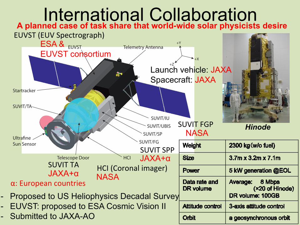
International Collaboration�
ESA & EUVST consortium �
NASA�
NASA�
JAXA+α�
JAXA+α�
Launch vehicle: JAXA Spacecraft: JAXA�
A planned case of task share that world-wide solar physicists desire�
- Proposed to US Heliophysics Decadal Survey - EUVST: proposed to ESA Cosmic Vision II - Submitted to JAXA-AO�
α:#European#countries�
SUVIT#FGP�

Coordinated Observations�
Credit:#ESA/AOES�
Solar*Orbiter�
Credit:#NASA/JHU#APL�
(��������� ��"%������������ ����)�
� ��##�
Solar*Dynamic*Observatory*or*a*mission*of*full9disk*observa<ons�
SOLAR8C�

Summary�• SOLAR-C is a mission to understand the causal
linkage between solar magnetic fields and active phenomena on the Sun and in the heliosphere.
• SOLAR-C equips three major payloads to elucidate fundamental problems in Helio-physics
by high-resolution (0.1”−0.3”) imaging & spectroscopy with temporally stable chromospheric magnetometry.
• All telescopes of the SOLAR-C have capability to observe coronal rains with enough spatial resolution, enough cadence, and enough coverage of temperature.
Top Related