


Languages
Pages
Legal

1
THE GREEN FIRE
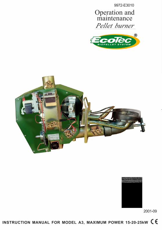
Operation andmaintenancePellet burner
INSTRUCTION MANUAL FOR MODEL A3, MAXIMUM POWER 15-20-25kW
2001-09
9972-E3010

2
THE GREEN FIRE
Keep this instructionbook handy in case you
need it in the future.
Read through the instruction book carefully
before you use your EcoTec Pellet Instal-
lation.
The power of your Pellet burner is
calculated on the maximum amount of
pellets that can be fed in and burned in the
burn pot in one hour (using normal wood
pellets, with an average value from our fuel
spec.).
Contact Sahlins EcoTec AB if you require
higher power, between 25-300 kW.
IMPORTANT!
Do not remove the green protective cover over the
burner, or the cover for the control unit unless the power
(main supply) to the installation is switched off.
FOLLOW THE INSTRUCTION IN THIS BOOK CAREFULLY AND CARRY OUTTHE RECOMMENDED CARE AND MAINTENANCE.
3
THE GREEN FIRE
CO
NT
EN
TS
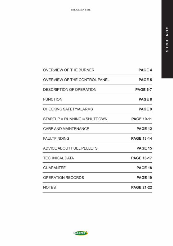
OVERVIEW OF THE BURNER
OVERVIEW OF THE CONTROL PANEL
DESCRIPTION OF OPERATION
FUNCTION
CHECKING SAFETY/ALARMS
STARTUP ∞ RUNNING ∞ SHUTDOWN
CARE AND MAINTENANCE
FAULTFINDING
ADVICE ABOUT FUEL PELLETS
TECHNICAL DATA
GUARANTEE
OPERATION RECORDS
NOTES
PAGE 4
PAGE 5
PAGE 6-7
PAGE 8
PAGE 9
PAGE 10-11
PAGE 12
PAGE 13-14
PAGE 15
PAGE 16-17
PAGE 18
PAGE 19
PAGE 21-22
4
THE GREEN FIRE
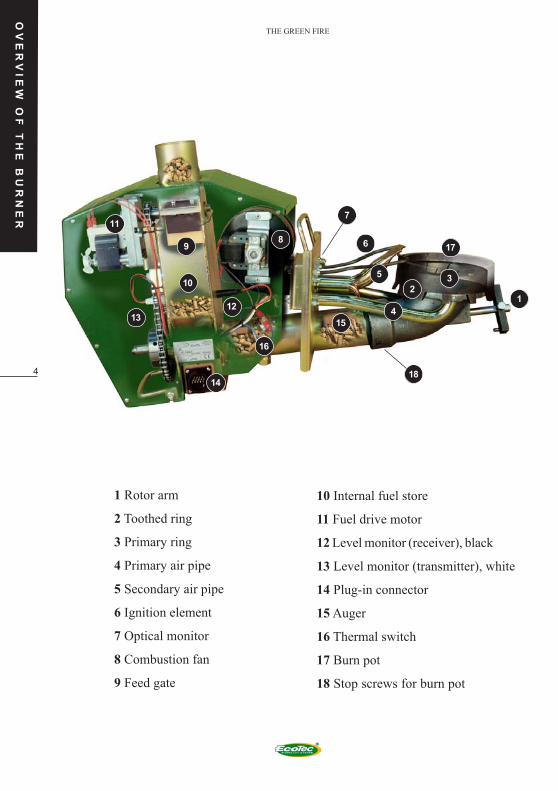
1 Rotor arm
2 Toothed ring
3 Primary ring
4 Primary air pipe
5 Secondary air pipe
6 Ignition element
7 Optical monitor
8 Combustion fan
9 Feed gate
10 Internal fuel store
11 Fuel drive motor
12 Level monitor (receiver), black
13 Level monitor (transmitter), white
14 Plug-in connector
15 Auger
16 Thermal switch
17 Burn pot
18 Stop screws for burn pot
OV
ER
VIE
W O
F T
HE
BU
RN
ER
12
9
3
41
7
6
5
2
8
10
15
14
11
17
16
1213
18
5
THE GREEN FIRE
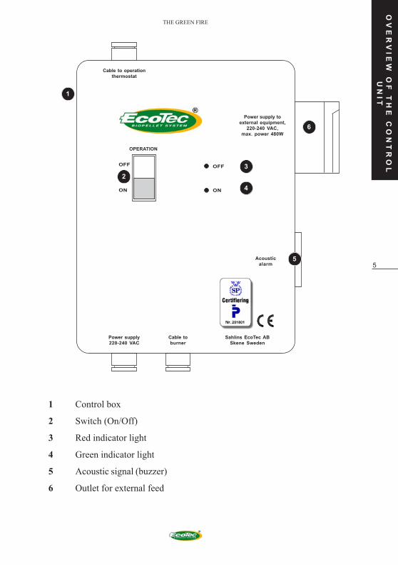
1 Control box
2 Switch (On/Off)
3 Red indicator light
4 Green indicator light
5 Acoustic signal (buzzer)
6 Outlet for external feed
OV
ER
VI
EW
OF
TH
E C
ON
TR
OL
UN
IT
OFF
DRIFTBRÄNNARE
ON
OFF
ON
1
5
3
4
2
6
OPERATION
Power supply toexternal equipment,
220-240 VAC,max. power 480W
Cable to operationthermostat
Acousticalarm
Sahlins EcoTec ABSkene Sweden
Cable toburner
Power supply220-240 VAC
6
THE GREEN FIRE
OP
ER
AT
IO
N
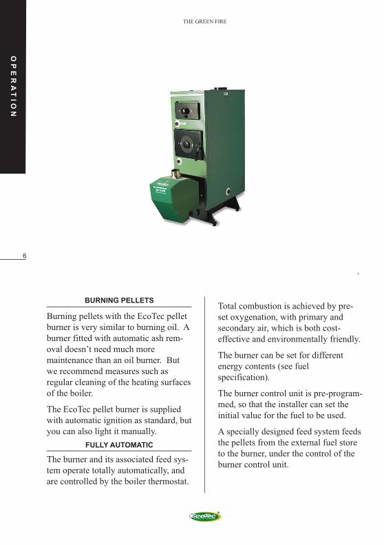
BURNING PELLETS
Burning pellets with the EcoTec pellet
burner is very similar to burning oil. A
burner fitted with automatic ash rem-
oval doesn’t need much more
maintenance than an oil burner. But
we recommend measures such as
regular cleaning of the heating surfaces
of the boiler.
The EcoTec pellet burner is supplied
with automatic ignition as standard, but
you can also light it manually.
FULLY AUTOMATIC
The burner and its associated feed sys-
tem operate totally automatically, and
are controlled by the boiler thermostat.
Total combustion is achieved by pre-
set oxygenation, with primary and
secondary air, which is both cost-
effective and environmentally friendly.
The burner can be set for different
energy contents (see fuel
specification).
The burner control unit is pre-program-
med, so that the installer can set the
initial value for the fuel to be used.
A specially designed feed system feeds
the pellets from the external fuel store
to the burner, under the control of the
burner control unit.

7
THE GREEN FIRE
OP
ER
AT
IO
N
THE FEED SYSTEM
The feed system is based on the safety
principle of cutting of the flow of fuel
by free fall (in the tube) between the
external feed and the burner.
NB! THE ECOTEC BURNER CANNOT BE
USED WITH FEED SYSTEMS OTHER
THAN THE ORIGINAL ECOTEC FEED
SYSTEM.
ORIGINAL MATNINGSSYSTEM
AUTOMATIC ASH REMOVAL
All burners can be fitted with auto-
matic ash removal (see pages 23-24,
accessories). For a simple installation,
in which the ash pan can be placed
under the ash remover, there should be
a gap of 250 mm under the burner. The
ash must be fed to a separate ash pan if
there is less space.
You can also remove the ash by taking
the burner out of the boiler, so that the
combustion chamber is exposed, or by
putting a suction nozzle into the ash
removal hole and sucking the ash out
to a special ash box (accessory for an
ordinary vacuum cleaner).
NB! ALWAYS TAKE CARE WITH ASH AS
IT COULD STILL BE ALIGHT.
PELLET
STOCK
8
THE GREEN FIRE
FU
NC
TI
ON
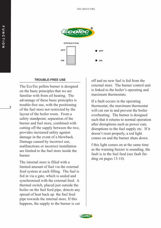
TROUBLE-FREE USE
The EcoTec pellets burner is designed
on the basic principles that we are
familiar with from oil heating. The
advantage of these basic principles is
trouble-free use, with the positioning
of the fuel store not restricted by the
layout of the boiler room. From a
safety standpoint, separation of the
burner and fuel store, combined with
cutting off the supply between the two,
provides increased safety against
damage in the event of a blowback.
Damage caused by incorrect use,
malfunctions or incorrect installation
are limited to the fuel store inside the
burner.
The internal store is filled with a
limited amount of fuel via the external
feed system at each filling. The fuel is
fed in via a gate, which is sealed and
synchronised with the external feed. A
thermal switch, placed just outside the
boiler on the fuel feed pipe, detects any
spread of heat back up the fuel feed
pipe towards the internal store. If this
happens, the supply to the burner is cut
off and no new fuel is fed from the
external store. The burner control unit
is linked to the boiler’s operating and
maximum thermostats.
If a fault occurs in the operating
thermostat, the maximum thermostat
will cut out in and prevent the boiler
overheating. The burner is designed
such that it returns to normal operation
after disruptions such as power cuts,
disruptions to the fuel supply etc. If it
doesn’t reset properly, a red light
comes on and the burner shuts down.
f this light comes on at the same time
as the warning buzzer is sounding, the
fault is in the fuel feed (see fault fin-
ding on pages 13-14).
OFF
DRIFTBRÄNNARE
ON
OFF
ON
OPERATION
9
THE GREEN FIRE
SA
FE
TY
CH
EC
KS
/ A
LA
RM
S
ALWAYS NOTE AND CHECK THE
FOLLOWING
1 The main switch should always be
on (the red or green light should be
on).
2 The connections between the
burner and the external feed system
should be properly attached and
sealed.
3 The plates of the gate feeder should
not be damaged or discoloured, and
the seal onto the
walls of the gate housing should be
good.
4 You can easily check the sealing of
the gate feeder plates by turning
down the operating thermostat, and
letting the burner remain off for a
prolonged period (up to 1 hour).
IF THE BURNER STARTS DURING THE OFF
PERIOD, DESPITE THE FACT THAT THE
OPERATING THERMOSTAT HAS NOT
CALLED FOR HEAT, CHECK THE CAUSE
AND RECTIFY IT. IF YOU CAN’T FIND THE
PROBLEM, CONTACT THE INSTALLER
IMMEDIATELY TO TAKE MEASURES.

10
THE GREEN FIREST
AR
TU
P °
R
UN
NI
NG
°
SH
UT
DO
WN
START UP
Before you start the burner, make sure
that there is power to the control unit,
by checking that the red light is on (the
main switch should always be on) and
that pellets come from the external
feed auger. An external feed system is
filled by removing the hose and inser-
ting the connector, which is normally
plugged into the control cabinet, into
an ordinary wall socket. When the
external auger has been filled, move
the plug back to the control cabinet and
the hose can be installed.
To start the burner, press “ON.” The
burner fan starts, and also the auger
motor, which feeds fuel from the
internal store to the burn pot along the
burner’s auger pipe. At the same time,
the ignition element starts to glow.
When the fuel level reaches the bottom
of the air slits, press OFF. Pour on
some fire lighting fluid and light
manually. Wait about 2 minutes, then
press ON. Electric ignition is only used
after a power cut.
The ignition process from a cold burner
can vary in length, depending on how
much fuel there is in the burner auger,
the quality of the pellets, the position
of the igniter etc. The burner attempts
to light for up to 30 minutes, after
which it shuts down, which is indicated
by the red lamp. You can also light it
using fire lighters, etc.
OFF
ON
OFF
DRIFTBRÄNNARE
ON
OPERATION
MAIN BREAKER(Pellet burner)
STOP
SHOULD ONLY BESWITCHED OFF
DURING SERVICING
11
THE GREEN FIRE ST
AR
TU
P °
R
UN
NI
NG
°
SH
UT
DO
WN
OPERATING/RUNNING
When running, the boiler’s running and
maximum thermostats control the
functions of the burner.
The burner does not have any
intermediate modes. It is either ON or
OFF.
In order to guarantee reliable ignition
during normal thermostat operation,
without needing to use the ignition
spiral, the burner starts after one hour’s
stoppage and runs for one minute. We
call this phase the heat activation
phase.
The green light indicates that the bur-
ner is running.
A red light indicates a stoppage (Please
refer to pages 13-14, Fault Finding).
THE MAIN SWITCH SHOULD ONLY BE
SWITCHED OFF DURING SERVICING.
DON’T FORGET TO SWITCH IT BACK ON
WHEN THE SERVICING IS COMPLETE.
OFF
• Press “OFF” to shut down the
burner.
• Do not switch off the main switch.
• In the “OFF” position, the red light
on the control box should always
be on, indicating the main supply is
off.
ASH REMOVAL
All burning of solid fuels requires a
little more maintenance than does oil,
even when the burning takes place
automatically in an EcoTec pellets
burner. Most of the maintenance is
concerned with the fuel and its quality,
which is shown by the following
comparison: Good pellets contain no
more than 0.5% ash, which means that
the ash has to be emptied every 3-4
weeks, depending on the type of boiler.
If you burn pellets with 2% ash, you
will need to empty at least once a week
under the same conditions.
Shut down the burner about one hour
before you remove the ash and perform
checks. NB: Don’t switch off the main
switch until you are about to start work
on the boiler. To ensure safe and trou-
ble free operation, you should carry out
the following measures and checks
every time you empty the ash, or at
least once a month until you have
gained enough experience about the
maintenance frequency required.
12
THE GREEN FIRE
CA
RE
AN
D M
AI
NT
EN
AN
CE
MAINTENANCE
• Pay particular attention when you
get a new delivery of pellets or use
a different type.
• Emptying the ashes and brushing
the boiler and its channels clean
can be done by sucking through
the burner’s ash hatch or by
removing the burner from the
combustion area.
• You always have to remove the
burner to check the burner cup.
(Check that the three screws that
hold the burner cup have been
tightened, please refer to page 4).
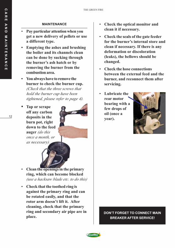
• Tap or scrape
off any carbon
deposits in the
burn pot, right
down to the feed
auger (do this
once a month, or
as necessary).
• Clean the openings in the primary
ring, which can become blocked
(use a hacksaw blade etc. to do this)
• Check that the toothed ring is
against the primary ring and can
be rotated easily, and that the
rotor arm doesn’t lift it. After
cleaning, check that the primary
ring and secondary air pipe are in
place.DON’T FORGET TO CONNECT MAIN
BREAKER AFTER SERVICE!
• Check the optical monitor and
clean it if necessary.
• Check the seals of the gate feeder
for the burner’s internal store and
clean if necessary. If there is any
deformation or discoloration
(leaks), the bellows should be
changed.
• Check the hose connections
between the external feed and the
burner, and reconnect them after
servicing.
• Lubricate the
rear motor
bearing with a
few drops of
oil (once a
year).

13
THE GREEN FIRE
FAULT: THE RED LIGHT IS ON AND THE
AUDIBLE ALARM IS SOUNDING
This only occurs if there is a shortageof fuel in the internal store.
CHECK: That there are pellets in theexternal store.
ACTION: Fill with pellets.
CHECK: That the angle of the augerisn’t too steep or the flow has stoppedbecause an arch has formed in the bot-tom of the external store.
ACTION: Put the auger at a gentlerangle and turn it back and forth a fewtimes. It should be positioned in thecentre of the external store.
CHECK: That the drive motor for theexternal auger is working and that theshaft of the motor is driving the auger.
ACTION: Remove the hose from theburner, insert the plug into an ordinarywall outlet and check that the motorand auger turn round. Tighten thesocket cap screw on flat on the motorspindle. If there is a fault in the motor,contact the installer.
CHECK: That the hose to the burnerisn’t at too flat an angle.
ACTION: Change the angle so thepellets don’t get blocked.
CHECK: That an arch hasn’t formed inthe internal store.
ACTION: The only reasons an archforms in the store are damp pellets ofoverfilling. Tap the store. Change thepellets immediately. Damp pellets cancause a total stoppage and mal-functions. If you have overfilled youstore you must contact the installer.
FAULTFINDING
Most faults that occur are caused by
poor quality pellets, or the way they
have been handled or stored.
Check your deliveries carefully,
preferably before you accept them.
Remember that for your safety, we
have pre-programmed the burner to
stop and sound an alarm if it can’t
rectify the fault itself.
FAULT: ALL LIGHTS ARE OFF
CHECK: That the main switch is on and
the fuses in the burner control unit are
intact.
ACTION: Switch on the main switch or
replace a blown fuse in the control unit.
NOTE: Switch off the main switch
before you change the fuse. Contact
the installer.
FAULT: THE RED LIGHT IS ON AND THE
BURNER MOTOR RUNS CONSTANTLY.
CHECK: If the re-settable thermal cut-
out has tripped.
ACTION: Press the button on the side of
the thermal switch in. Switch the mains
voltage off and then on.
ACTION: Change the gate feeder flaps if
they are discoloured or distorted.
ACTION: Check that the flue damper is
fully open and that the fly ash in the
smoke channels inside the stove is
cleared off.
FA
UL
TF
IN
DI
NG

14
THE GREEN FIRE
FA
UL
TF
IN
DI
NG
FAULT: THE RED LIGHT COMES ON
CHECK: If the maximum thermostat has
cut out. Switch the burner switch off
and on again, without resetting the
maximum thermostat. If the burner
doesn’t start and the diode still shows
red, the fault is: A the maximum
thermostat has tripped. If the burner
starts and the diode shows red the fault
is: B the optical monitor can’t see any
light in the combustion chamber.
ACTION: A If the maximum thermostat
has tripped out, reset the button on the
maximum thermostat and restart. A
common reason is burning wood
together with pellets. If you can’t find
the cause of the overheating, you will
need to check the operating thermostat
CHECK: B If there is still fuel in the burn
pot and auger pipe, go to B1.
B If there is no fuel in the burner, go to
B2.
CHECK: B1 That the combustion
chamber is not overfilled with ash.
ACTION: Remove the ash.
CHECK: B1 That the optical monitor
isn’t sooty, preventing it from seeing
the light.
ACTION: Wipe the optical monitor
clean. If the boiler has been installed
correctly, the optical monitor shouldn’t
get sooty between normal inspections.
Air leakage or a burner too close to a
cold ceiling can cause soot to build up,
as can insufficient air coming into the
boiler room.
Rectify this as soon as possible. If the
boiler has been installed incorrectly,
the optical monitor could also get too
hot and stop detecting the light.
Contact the installer if you suspect that
the boiler has been incorrectly
installed.
CHECK: B2 Start the burner and check
that the drive motor, gate shaft and
auger shaft are rotating in the burn pot.
ACTION: Contact the installer to deal
with it.
CHECK: B2 That the level monitors for
the internal store indicate low fuel
level.
ACTION: Start the burner and check
that the external auger starts and feeds
fuel to the burner. If it does not do so,
the burner level monitors have reacted
to back pressure in the system and have
shut off the fuel supply. If the burner
level monitors have reacted to back
pressure in the system and shut off the
fuel feed, open the boiler’s damper and
clean out fly ash from the flue
channels. Poor draught is usually due
to a defective chimney, which should
be attended to as soon as possible.
Masonry chimneys with large cold
surfaces and cold downdraughts can
also cause back pressure, especially at
warm times of the year. If this is the
case, a flue fan should be fitted.
Contact the installer for further advice.
You should also contact the installer if
the level monitors aren’t working as
described above.

15
THE GREEN FIRE
AD
VI
CE
AB
OU
T
FU
EL
P
EL
LE
TS
RAW MATERIALS
Fuel pellets can be made from various
raw materials. Wood is most common
but there are already suitable
alternative raw materials on the
market.
The raw materials have different char-
acteristics, which give them advantages
and disadvantages as pellet fuel.
Important factors are energy value, ash
content, moisture content, effect on the
environment and last but not least
price.
You should choose the fuel that has the
lowest cost per unit of energy, after
considering how the fuel will operate
in the boiler, the ash content and the
environmental effects.
The EcoTec pellet burner is designed to
be able to burn most types of pellet
fuel.
If you are unsure about anything, read
our pamphlet about pellet fuel, and
take careful note of the effects of
changing fuel.
PELLET QUALITY
Most of the problems that can arise due
to poor fuel quality are due to
shortcomings in manufacture, handling
and intermediate storage, before the
fuel reaches the final customer.
If there are high levels of fine particles,
the fault is usually in the
manufacturing, or separation during
storage at the distribution points. If
there is clinker in the ash, this is due to
silicate contamination and cannot be
seen before burning. Pellets can get
damp during intermediate handling and
transport.
If possible, check on the truck to see
that you are getting clean and dry
pellets, and not sawdust.
YOU SHOULD DISPOSE OF DAMP
PELLETS IMMEDIATELY
APPROVED FUEL SPECIFICATION
WEIGHT 600-750 kg/m3
ENERGY CONTENT 4.7-5.0 kWh/kg
SIZE/DIAMETER 6-12 mm
SIZE/LENGTH NB max.35 mm
MOISTURE CONTENT max. 12%
ASH CONTENT BY WEIGHT 0.5-1%
FINES CONTENT BY WEIGHT max. 3%
ASH MELTING POINT 1100°C

16
THE GREEN FIRE
TE
CH
NI
CA
L
DA
TA
J1 ON - OFF J l0 Red LED
J3 Level monitor (receiver) J11 220V AC
J5 Optical monitor J13 Internal feed motor
J6 Operation thermostat 5V DC J15 Alarm
J7 Temperature switch J17 Fumer
J8 Max. temp. Switch 5V DC J19 External feed motor
J9 Green LED J20 Combustion fan
J15-1 o. J10-2 Level guard (transmitter)
J 11
230 V AC
J 9
J 10
J 15
J 17J 16 J 20 J 13 J 14 J 19
J 8
J 6
J 7
J 3
J 1
F
M
M
F N
J 5
CONNECTION DIAGRAM - CONTROL CARD

17
THE GREEN FIRE
CONNECTION TABLE - BURNER
DESCRIPTION ITEM NO. 18 CONDUITS 4 CONDUITS 3 CONDUITS COLLOUR ON
CABLE NO. TO THERMOSTAT EXT. FEEDER BOX COVER
CABLE NO. CABLE NO. CABLE
Combustion fan J20-1 1
Combustion fan J20-2 2
Level monitor IR transmitter J15-1 3
Level monitor IR transmitter J10-2 4
Level monitor IR receiver J3-1 5
Level monitor IR receiver J3-2 6
Optical monitor J5-1 7
Optical monitor J5-2 8
Internal feed motor J13-1 9
Internal feed motor J13-2 10
Temperature switch screw J7-1 11
Temperature switch screw J7-2 12
Operatin thermostat J6-1 1
Operatin thermostat J6-2 2
Max. thermostat J8-1 3
Max. thermostat J8-2 4
External feeder J19-1 1
External feeder J19-2 2
Fumer J17-2 13
Fumer J17-3 14
Switch OFF J1-l white
Switch ON J1-3 red
Buzzer alarm (+) J15-1 red
Buzzer alarm J15-2 white
LED, green (-) J9-1 red
LED, green J9-2 white
LED, red (-) J10-1 red
LED, red J10-2 white
Spare 1 15
Spare 2 16
Spare 3 17
TE
CH
NI
CA
L
DA
TA
NOTE! 5VDC
NOTE! 5VDC
18
THE GREEN FIRE
DR
IF
TS
JO
UR
NA
L
GU
AR
AN
TE
E
/
CL
AI
MS
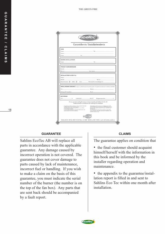
GUARANTEE
Sahlins EcoTec AB will replace all
parts in accordance with the applicable
guarantee. Any damage caused by
incorrect operation is not covered. The
guarantee does not cover damage to
parts caused by lack of maintenance,
incorrect fuel or handling. If you wish
to make a claim on the basis of this
guarantee, you must indicate the serial
number of the burner (the number is on
the top of the fan box). Any parts that
are sent back should be accompanied
by a fault report.
CLAIMS
The guarantee applies on condition that
• the final customer should acquaint
himself/herself with the information in
this book and be informed by the
installer regarding operation and
maintenance.
• the appendix to the guarantee/instal-
lation report is filled in and sent to
Sahlins Eco Tec within one month after
installation.
19
THE GREEN FIRE
DATE ACTION
OPERATION RECORDS
OP
ER
AT
IN
G
LO
G

20
THE GREEN FIRE
NOTES
NO
TE
S

21
THE GREEN FIRE
NOTES
NO
TE
S

22
THE GREEN FIRE
Sahlins EcoTec
Our business mission is simple. Proximity, satisfied
customers and care of the environment.
We collaborate with authorised retailers, who offer full
service. Our quality philosophy is based on high technical
competence and constant development work. We make
burners from
7 kW up to 300 kW. We believe that we can offer the best
products on the market and lower fuel costs.
We do not regard pellets as a fuel of the future, it is a fuel
which is available right now. The earth’s resources are not
inexhaustible, and our environment can not withstand
unlimited abuse. For this reason, it is important to invest
in renewable, environmentally friendly and low-cost
sources of energy.
If you would like to comment on our products, or want the
name of our nearest dealer, please phone, write or fax us.
We are here for your sake
Sahlins EcoTec AB, Box 2103, 511 02 Skene. Phone. +46 320-18140. Fax +46 320-42160.
e-mail: [email protected] www.ecotec.net
SAHLINS
®
Top Related