


![Effect of Ethanolamines on Corrosion Inhibition of Ductile ...corrosion.andong.ac.kr/publication/pdf/[CST] 201608 Effect of... · In the case of ductile cast iron, however, ... can](https://static.fdocuments.in/doc/165x107/5b03281f7f8b9a8c688bb3a6/effect-of-ethanolamines-on-corrosion-inhibition-of-ductile-cst-201608-effect.jpg)
Languages
Pages
Legal


materials
Article
The Effect of the Static Load in the UNSM Process onthe Corrosion Properties of Alloy 600
Ki Tae Kim and Young Sik Kim *
Research Center for Energy and Clean Technology, School of Materials Science and Engineering,Andong National University, 1375 Gyeongdong-ro, Andong, Gyeongbuk 36729, Korea;[email protected]* Correspondence: [email protected]; Tel.: +82-54-820-5504
Received: 3 September 2019; Accepted: 20 September 2019; Published: 27 September 2019 �����������������
Abstract: To suppress stress corrosion-cracking, compressive residual stresses, such as shot peening,laser peening, water jet peening, ultrasonic peening, and ultrasonic nanocrystal surface modification(UNSM) are utilized. However, among the numerous techniques, there is little research aboutthe corrosion effect of detailed conditions, such as static load or amplitude in UNSM. A study onUNSM among various techniques of adding compressive residual stress to Alloy 600 was conducted.The focus of this study was on the effect of the static load in UNSM on the corrosion properties of Alloy600. Microstructure analysis was conducted using an optical microscope (OM), a scanning electronmicroscope (SEM), and electron backscattering diffraction (EBSD), while compressive residual stresswas measured using a nano-indentation technique. A cyclic polarization test and the AC (AlternatingCurrent)-impedance measurement were both used to analyze the corrosion properties. An increase instatic load under critical static load enhanced the grain boundary diffusion, consequently strengthenedthe passive film, and facilitated the surface diffusion, thereby improving the passivation of Alloy600. However, higher static loads over the critical value can lead to an increase in the frictionbetween the striking tip and the surface, thereby creating an overlapped wave, which reduces thecorrosion properties.
Keywords: alloy 600; UNSM; corrosion; static load; residual stress
1. Introduction
Ni alloy is among the fcc (face centered cubic) crystal structures; it has good strength, ductility,resistance to corrosion, and oxidation resistance at high temperatures [1]. Therefore, it is commonlyused as a nuclear power plant material because of its high temperature corrosion and high temperaturestrength. Alloy 600 and Alloy 690 are used in nuclear reactors and steam generators in the nuclearpower plants’ primary system [2,3]. There are reports that Alloy 600 is susceptible to primary waterstress corrosion cracking in field applications [4–7], hence Alloy 690 has been used for new plantsor as a replacement material for the Alloy 600. However, Alloy 600 is used in majority of the plants.SCC (stress corrosion cracking) constitutes the major damage due to Alloy 600, and the damagedareas include the CMDR (control rod drive mechanism) nozzle of the reactor head, the BMI (bottommounted instrumentation) nozzle of the reactor bottom, a dissimilar metal weld of the RPV (reactorpressure vessel) nozzle, and the heat transfer tube of the steam generator [8].
There are many techniques to mitigate the stress corrosion cracking of Alloy 600, which includesubstitution with high corrosion resistant materials, modification of water chemistry, and reductionof residual stress. Among these remedies, the reduction of residual stress, including tensile stressand compressive stress, can be achieved through surface treatment. Techniques used for addingcompressive residual stresses to materials include: shot peening [9–11], laser peening [12–16], water jet
Materials 2019, 12, 3165; doi:10.3390/ma12193165 www.mdpi.com/journal/materials

Materials 2019, 12, 3165 2 of 14
peening [17,18], ultrasonic peening [19,20], and ultrasonic nanocrystal surface modification (UNSM),with many studies still ongoing. Water jet peening and laser peening have been used to mitigate SCC,since 2001 and 2004, respectively. In the USA, nuclear power plants, such as Byron-2, Braidwood-1,Wolf Creek and ANO-1 in 2016; and Callaway, Byron-1, Braidwood-2, and ANO-2 in 2017–2018 usedlaser peening, and further research has been conducted in this regard [2].
Regarding the UNSM process, the material is impacted with a hard, rigid pin moving at anultrasonic frequency, typically 20 kHz. A tungsten carbide (WC) tip is then attached to an ultrasonichorn, which strikes the specimen surface at about 20,000 times per second with 1000 to 10,000 shotsmade per square millimeter within a very short time. This impact deforms the surface of the targetmaterial and converts its microstructure into nanocrystals. The plastic deformation produces a 1–2 mmdeep compressive residual stress field in the material. The combination of surface deformation, thenanostructured layer, and compressive residual stresses causes a delay in fatigue crack initiation [21].
The UNSM process consists of various variables, including static load, amplitude, pitch,tip diameter, speed, etc. Numerous studies have been performed using limited conditions amongUNSM process. The reported effects of UNSM on the mechanical properties and microstructure can besummarized as follows [22–26]: (i) The microstructure of the surface and under surface is convertedto a nanograined microstructure which enhanced yield strength, tensile strength, and hardness asa result of the Hall–Pitch strengthening mechanism. (ii) Very high levels of compressive residualstresses were formed (about (1–2 GPa). High compressive residual stress enhanced the resistanceto abrasion, wear, and fatigue lifetime. (iii) A new phase was formed—in an austenitic stainlesssteel, martensite can be formed through a UNSM process and the formed martensite phase in turnprotects the formation of the necking, since the new phase increases the interface strength betweenthe inside matrix and the nanograined surface. (iv) Surface roughness can also be improved. On theother hand, UNSM has influenced the corrosion properties as follows [27–31]: (i) Since the UNSMprocess strengthens the passive film, the pitting corrosion resistance of austenitic stainless steels canbe enhanced. (ii) UNSM treatment of aged, austenitic stainless steel reduced chromium carbide andcarbon segregation, hence improving the inter-granular corrosion resistance. (iii) Introduction of highcompressive residual stress enhanced the resistance to SCC. Additionally, many studies about theUNSM’s effect on Ti alloys and carbon steel have been performed. However, there is little research onthe detailed conditions, such as static load or amplitude, among UNSM conditions.
Therefore, this work focused on the effect of the static load to the surface via UNSM on thecorrosion properties of Alloy 600. The effects of the static load on the corrosion properties werediscussed on the basis of the microstructure, hardness, and residual stress.
2. Materials and Methods
2.1. Specimen
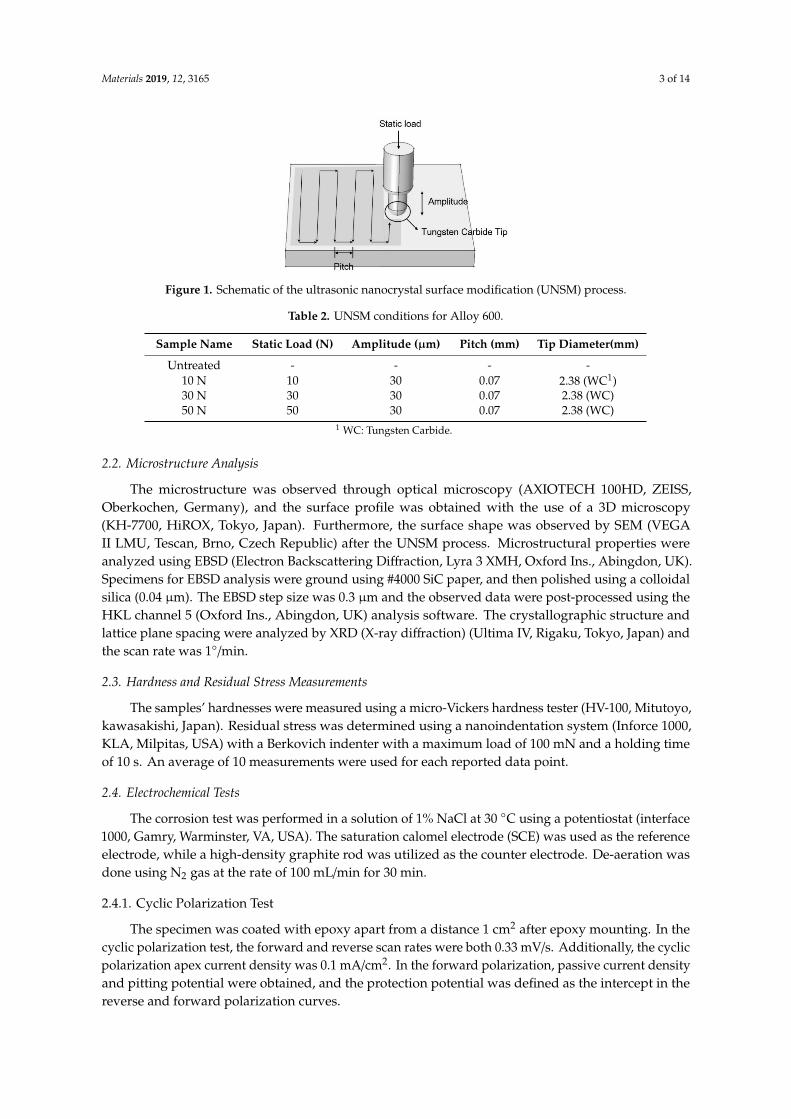
Alloy 600 was utilized for this study. Table 1 shows the chemical composition of the experimentalalloy. Heat treatment was applied to the specimen at 1040 ◦C for 7 min. UNSM treatment was applied tothe surface using the UNSM equipment (Design Mecha-LM20 UNSM system, Asan, Korea). The UNSMprocess is schematically presented in Figure 1 and UNSM treatment conditions are summarized asin Table 2. The surface preceding the UNSM treatment was ground with #2000 SiC abrasive paper.As illustrated in Figure 1, UNSM treatment was applied in a zig-zag manner and 2.38 mm tungstencarbide tip was used with an amplitude of 30 µm and a pitch of 0.07 mm, as summarized in Table 2.This work controlled the static load—10 N, 30 N, and 50 N.
Table 1. Chemical composition of Alloy 600 used in the experiments (wt. %). (This chemical compositionis provided by the manufacturer).
Ni Cr Fe C Mn S Si Cu
73.13 16.35 9.42 0.07 0.21 0.002 0.29 0.01
Materials 2019, 12, 3165 3 of 14Materials 2019, 12, x FOR PEER REVIEW 3 of 15
Figure 1. Schematic of the ultrasonic nanocrystal surface modification (UNSM) process.
Table 2. UNSM conditions for Alloy 600.
Sample Name Static Load (N) Amplitude (μm) Pitch (mm) Tip Diameter(mm) Untreated - - - -
10 N 10 30 0.07 2.38 (WC1) 30 N 30 30 0.07 2.38 (WC) 50 N 50 30 0.07 2.38 (WC)
1 WC: Tungsten Carbide.
2.2. Microstructure Analysis
The microstructure was observed through optical microscopy (AXIOTECH 100HD, ZEISS, Oberkochen, Germany), and the surface profile was obtained with the use of a 3D microscopy (KH-7700, HiROX, Tokyo, Japan). Furthermore, the surface shape was observed by SEM (VEGA II LMU, Tescan, Brno, Czech Republic) after the UNSM process. Microstructural properties were analyzed using EBSD (Electron Backscattering Diffraction, Lyra 3 XMH, Oxford Ins., Abingdon, UK). Specimens for EBSD analysis were ground using #4000 SiC paper, and then polished using a colloidal silica (0.04 μm). The EBSD step size was 0.3 μm and the observed data were post-processed using the HKL channel 5 (Oxford Ins., Abingdon, UK) analysis software. The crystallographic structure and lattice plane spacing were analyzed by XRD (X-ray diffraction) (Ultima IV, Rigaku, Tokyo, Japan) and the scan rate was 1°/min.
2.3. Hardness and Residual Stress Measurements
The samples’ hardnesses were measured using a micro-Vickers hardness tester (HV-100, Mitutoyo, kawasakishi, Japan). Residual stress was determined using a nanoindentation system (Inforce 1000, KLA, Milpitas, USA) with a Berkovich indenter with a maximum load of 100 mN and a holding time of 10 s. An average of 10 measurements were used for each reported data point.
2.4. Electrochemical Tests
The corrosion test was performed in a solution of 1% NaCl at 30 °C using a potentiostat (interface 1000, Gamry, Warminster, VA, USA). The saturation calomel electrode (SCE) was used as the reference electrode, while a high-density graphite rod was utilized as the counter electrode. De-aeration was done using N2 gas at the rate of 100 mL/min for 30 min.
2.4.1. Cyclic Polarization Test
The specimen was coated with epoxy apart from a distance 1 cm2 after epoxy mounting. In the cyclic polarization test, the forward and reverse scan rates were both 0.33 mV/s. Additionally, the cyclic polarization apex current density was 0.1 mA/cm2. In the forward polarization, passive current density and pitting potential were obtained, and the protection potential was defined as the intercept in the reverse and forward polarization curves.
Figure 1. Schematic of the ultrasonic nanocrystal surface modification (UNSM) process.
Table 2. UNSM conditions for Alloy 600.
Sample Name Static Load (N) Amplitude (µm) Pitch (mm) Tip Diameter(mm)
Untreated - - - -10 N 10 30 0.07 2.38 (WC1)30 N 30 30 0.07 2.38 (WC)50 N 50 30 0.07 2.38 (WC)
1 WC: Tungsten Carbide.
2.2. Microstructure Analysis
The microstructure was observed through optical microscopy (AXIOTECH 100HD, ZEISS,Oberkochen, Germany), and the surface profile was obtained with the use of a 3D microscopy(KH-7700, HiROX, Tokyo, Japan). Furthermore, the surface shape was observed by SEM (VEGAII LMU, Tescan, Brno, Czech Republic) after the UNSM process. Microstructural properties wereanalyzed using EBSD (Electron Backscattering Diffraction, Lyra 3 XMH, Oxford Ins., Abingdon, UK).Specimens for EBSD analysis were ground using #4000 SiC paper, and then polished using a colloidalsilica (0.04 µm). The EBSD step size was 0.3 µm and the observed data were post-processed using theHKL channel 5 (Oxford Ins., Abingdon, UK) analysis software. The crystallographic structure andlattice plane spacing were analyzed by XRD (X-ray diffraction) (Ultima IV, Rigaku, Tokyo, Japan) andthe scan rate was 1◦/min.
2.3. Hardness and Residual Stress Measurements
The samples’ hardnesses were measured using a micro-Vickers hardness tester (HV-100, Mitutoyo,kawasakishi, Japan). Residual stress was determined using a nanoindentation system (Inforce 1000,KLA, Milpitas, USA) with a Berkovich indenter with a maximum load of 100 mN and a holding timeof 10 s. An average of 10 measurements were used for each reported data point.
2.4. Electrochemical Tests
The corrosion test was performed in a solution of 1% NaCl at 30 ◦C using a potentiostat (interface1000, Gamry, Warminster, VA, USA). The saturation calomel electrode (SCE) was used as the referenceelectrode, while a high-density graphite rod was utilized as the counter electrode. De-aeration wasdone using N2 gas at the rate of 100 mL/min for 30 min.
2.4.1. Cyclic Polarization Test
The specimen was coated with epoxy apart from a distance 1 cm2 after epoxy mounting. In thecyclic polarization test, the forward and reverse scan rates were both 0.33 mV/s. Additionally, the cyclicpolarization apex current density was 0.1 mA/cm2. In the forward polarization, passive current densityand pitting potential were obtained, and the protection potential was defined as the intercept in thereverse and forward polarization curves.

Materials 2019, 12, 3165 4 of 14
2.4.2. AC-Impedance Measurement
The test specimen was similar to that of the polarization test. Before measuring, passivation wastreated at +0 mV (SCE) for 30 min. AC impedance was measured at a passivation potential of between10 kHz to 0.01 Hz, and the AC voltage amplitude was 10 mV.
3. Results
3.1. The Effect of the Static Load in UNSM Treatment on the Microstructure of Alloy 600
UNSM treatment causes a change in various properties of materials. Figure 2 shows the effectof the static load in UNSM treatment on the appearance of Alloy 600 through an optical microscope(magnification: ×50). The static load was varied between 10 N, 30 N, and 50 N. The surface appearanceswere similar to each other regardless of the static load; many micro valleys were observed. These valleyswere associated to the applied load and the pitch of UNSM treatment. Figure 3 shows the 3D microscopeobservation. Figure 3 also reveals the effect of the static load in UNSM treatment on the surfacetopography of Alloy 600 through a 3D microscope (magnification: ×600). An increase in the static loadresults in a deeper valley-depth as follows: 9.0 µm for 10 N, 11.1 µm for 30 N, and 11.2 µm for 50 Nspecimens. It suggested that valley depth may be associated with the intrinsic mechanical properties,such as yield strength and elastic modulus [21].
Materials 2019, 12, x FOR PEER REVIEW 4 of 15
2.4.2. AC-Impedance Measurement
The test specimen was similar to that of the polarization test. Before measuring, passivation was treated at +0 mV (SCE) for 30 min. AC impedance was measured at a passivation potential of between 10 kHz to 0.01 Hz, and the AC voltage amplitude was 10 mV.
3. Results
3.1. The Effect of the Static Load in UNSM Treatment on the Microstructure of Alloy 600
UNSM treatment causes a change in various properties of materials. Figure 2 shows the effect of the static load in UNSM treatment on the appearance of Alloy 600 through an optical microscope (magnification: ×50). The static load was varied between 10 N, 30 N, and 50 N. The surface appearances were similar to each other regardless of the static load; many micro valleys were observed. These valleys were associated to the applied load and the pitch of UNSM treatment. Figure 3 shows the 3D microscope observation. Figure 3 also reveals the effect of the static load in UNSM treatment on the surface topography of Alloy 600 through a 3D microscope (magnification: ×600). An increase in the static load results in a deeper valley-depth as follows: 9.0 μm for 10 N, 11.1 μm for 30 N, and 11.2 μm for 50 N specimens. It suggested that valley depth may be associated with the intrinsic mechanical properties, such as yield strength and elastic modulus [21].
(a) (b) (c)
Figure 2. The effect of the static load in UNSM treatment on the appearance of Alloy 600 by optical microscope (×50): (a) 10 N; (b) 30 N; (c) 50 N.
(a) (b) (c)
Figure 3. The effect of the static load in UNSM treatment on the surface topography of Alloy 600 by 3D microscope (×600): (a) 10 N; (b) 30 N; (c) 50 N.
The cross-section of the microstructure by UNSM treatment was observed through an EBSD. Figure 4 shows the effect of the static load in UNSM treatment on the grain refinement depth profile of Alloy 600 by EBSD. Untreated specimen showed a typical austenitic microstructure, including twins and large grains (Figure 3a). Regardless of the static load, grain refinement proceeds from the surface into the matrix. In the case of the 10 N static load, the depth of grain refinement was about 40 μm; the depth was 80 μm for the 30 N static load, and about 90 μm for the 50 N static load. As shown in the figures below, the density of grain boundary was increased with an increase in the UNSM static load resulting in a deeper effective depth. Figure 5 summarizes the effect of the static load in UNSM treatment on the grain diameter distribution of Alloy 600. There are a lot of large grain diameters in the untreated specimen. By increasing the static load in UNSM treatment, the distribution function of smaller grain diameter was increased. Notably, the UNSM treatment could refine the grain size in addition to increasing the static load, amount of grain refinement, and the refined depth.
Figure 2. The effect of the static load in UNSM treatment on the appearance of Alloy 600 by opticalmicroscope (×50): (a) 10 N; (b) 30 N; (c) 50 N.
Materials 2019, 12, x FOR PEER REVIEW 4 of 15
2.4.2. AC-Impedance Measurement
The test specimen was similar to that of the polarization test. Before measuring, passivation was treated at +0 mV (SCE) for 30 min. AC impedance was measured at a passivation potential of between 10 kHz to 0.01 Hz, and the AC voltage amplitude was 10 mV.
3. Results
3.1. The Effect of the Static Load in UNSM Treatment on the Microstructure of Alloy 600
UNSM treatment causes a change in various properties of materials. Figure 2 shows the effect of the static load in UNSM treatment on the appearance of Alloy 600 through an optical microscope (magnification: ×50). The static load was varied between 10 N, 30 N, and 50 N. The surface appearances were similar to each other regardless of the static load; many micro valleys were observed. These valleys were associated to the applied load and the pitch of UNSM treatment. Figure 3 shows the 3D microscope observation. Figure 3 also reveals the effect of the static load in UNSM treatment on the surface topography of Alloy 600 through a 3D microscope (magnification: ×600). An increase in the static load results in a deeper valley-depth as follows: 9.0 μm for 10 N, 11.1 μm for 30 N, and 11.2 μm for 50 N specimens. It suggested that valley depth may be associated with the intrinsic mechanical properties, such as yield strength and elastic modulus [21].
(a) (b) (c)
Figure 2. The effect of the static load in UNSM treatment on the appearance of Alloy 600 by optical microscope (×50): (a) 10 N; (b) 30 N; (c) 50 N.
(a) (b) (c)
Figure 3. The effect of the static load in UNSM treatment on the surface topography of Alloy 600 by 3D microscope (×600): (a) 10 N; (b) 30 N; (c) 50 N.
The cross-section of the microstructure by UNSM treatment was observed through an EBSD. Figure 4 shows the effect of the static load in UNSM treatment on the grain refinement depth profile of Alloy 600 by EBSD. Untreated specimen showed a typical austenitic microstructure, including twins and large grains (Figure 3a). Regardless of the static load, grain refinement proceeds from the surface into the matrix. In the case of the 10 N static load, the depth of grain refinement was about 40 μm; the depth was 80 μm for the 30 N static load, and about 90 μm for the 50 N static load. As shown in the figures below, the density of grain boundary was increased with an increase in the UNSM static load resulting in a deeper effective depth. Figure 5 summarizes the effect of the static load in UNSM treatment on the grain diameter distribution of Alloy 600. There are a lot of large grain diameters in the untreated specimen. By increasing the static load in UNSM treatment, the distribution function of smaller grain diameter was increased. Notably, the UNSM treatment could refine the grain size in addition to increasing the static load, amount of grain refinement, and the refined depth.
Figure 3. The effect of the static load in UNSM treatment on the surface topography of Alloy 600 by 3Dmicroscope (×600): (a) 10 N; (b) 30 N; (c) 50 N.
The cross-section of the microstructure by UNSM treatment was observed through an EBSD.Figure 4 shows the effect of the static load in UNSM treatment on the grain refinement depth profile ofAlloy 600 by EBSD. Untreated specimen showed a typical austenitic microstructure, including twinsand large grains (Figure 3a). Regardless of the static load, grain refinement proceeds from the surfaceinto the matrix. In the case of the 10 N static load, the depth of grain refinement was about 40 µm;the depth was 80 µm for the 30 N static load, and about 90 µm for the 50 N static load. As shown inthe figures below, the density of grain boundary was increased with an increase in the UNSM staticload resulting in a deeper effective depth. Figure 5 summarizes the effect of the static load in UNSMtreatment on the grain diameter distribution of Alloy 600. There are a lot of large grain diameters inthe untreated specimen. By increasing the static load in UNSM treatment, the distribution function ofsmaller grain diameter was increased. Notably, the UNSM treatment could refine the grain size inaddition to increasing the static load, amount of grain refinement, and the refined depth.

Materials 2019, 12, 3165 5 of 14
The surface layer subjected to plastic deformation presents a high-density dislocation throughstriking and produces a very small lamellae deformation-twin (DT). However, due to constant blows,the dislocation density is high, creating shear bands (SB) and cutting the DT/DT intersection. The DT andSB distort the microstructure and change into grains that are equiaxed and refined by the developmentof the newly formed grain boundaries, thereby reducing the grain size [32–34].
Materials 2019, 12, x FOR PEER REVIEW 5 of 14
The surface layer subjected to plastic deformation presents a high-density dislocation through striking and produces a very small lamellae deformation-twin (DT). However, due to constant blows, the dislocation density is high, creating shear bands (SB) and cutting the DT/DT intersection. The DT and SB distort the microstructure and change into grains that are equiaxed and refined by the development of the newly formed grain boundaries, thereby reducing the grain size [32–34].
(a) (b) (c) (d)
Figure 4. The effect of the static load in UNSM treatment on the grain refinement depth profile of Alloy 600 by EBSD (×600): (a) untreated; (b) 10 N; (c) 30 N; (d) 50 N.
(a) (b)
(c) (d)
Figure 5. The effect of the static load in UNSM treatment on the grain diameter distribution of Alloy 600 determined from the EBSD area of Figure 4: (a) untreated; (b) 10 N; (c) 30 N; (d) 50 N.
As described above, UNSM treatment changed the microstructure from the surface into the matrix. Figure 6 shows the effect of the static load in UNSM treatment on the hardness depth profile of Alloy 600. The outermost surface revealed the maximum hardness, higher static load, and higher surface hardness. The hardness depth profiles reduced greatly, irrespective of the static load, and the hardness-depth relationship showed a polynomial expression. Although a higher static load resulted in a little higher of a hardness depth profile, similar hardness attenuation was revealed as follows; y means the hardness (HV) and x implies the depth (μm) from top surface. As shown in below, the
Figure 4. The effect of the static load in UNSM treatment on the grain refinement depth profile of Alloy600 by EBSD (×600): (a) untreated; (b) 10 N; (c) 30 N; (d) 50 N.
Materials 2019, 12, x FOR PEER REVIEW 5 of 14
The surface layer subjected to plastic deformation presents a high-density dislocation through striking and produces a very small lamellae deformation-twin (DT). However, due to constant blows, the dislocation density is high, creating shear bands (SB) and cutting the DT/DT intersection. The DT and SB distort the microstructure and change into grains that are equiaxed and refined by the development of the newly formed grain boundaries, thereby reducing the grain size [32–34].
(a) (b) (c) (d)
Figure 4. The effect of the static load in UNSM treatment on the grain refinement depth profile of Alloy 600 by EBSD (×600): (a) untreated; (b) 10 N; (c) 30 N; (d) 50 N.
(a) (b)
(c) (d)
Figure 5. The effect of the static load in UNSM treatment on the grain diameter distribution of Alloy 600 determined from the EBSD area of Figure 4: (a) untreated; (b) 10 N; (c) 30 N; (d) 50 N.
As described above, UNSM treatment changed the microstructure from the surface into the matrix. Figure 6 shows the effect of the static load in UNSM treatment on the hardness depth profile of Alloy 600. The outermost surface revealed the maximum hardness, higher static load, and higher surface hardness. The hardness depth profiles reduced greatly, irrespective of the static load, and the hardness-depth relationship showed a polynomial expression. Although a higher static load resulted in a little higher of a hardness depth profile, similar hardness attenuation was revealed as follows; y means the hardness (HV) and x implies the depth (μm) from top surface. As shown in below, the
Figure 5. The effect of the static load in UNSM treatment on the grain diameter distribution of Alloy600 determined from the EBSD area of Figure 4: (a) untreated; (b) 10 N; (c) 30 N; (d) 50 N.
As described above, UNSM treatment changed the microstructure from the surface into thematrix. Figure 6 shows the effect of the static load in UNSM treatment on the hardness depth profileof Alloy 600. The outermost surface revealed the maximum hardness, higher static load, and highersurface hardness. The hardness depth profiles reduced greatly, irrespective of the static load, and thehardness-depth relationship showed a polynomial expression. Although a higher static load resulted

Materials 2019, 12, 3165 6 of 14
in a little higher of a hardness depth profile, similar hardness attenuation was revealed as follows;y means the hardness (HV) and x implies the depth (µm) from top surface. As shown in below,the surface hardness increases with an increase in the static load. However, the hardness depth profileof higher static load specimen decreases more compared to that of lower static load specimen. Finally,the effect of the static load on hardness depth profile diminished from the depth of about 500 µm.
Materials 2019, 12, x FOR PEER REVIEW 6 of 14
surface hardness increases with an increase in the static load. However, the hardness depth profile of higher static load specimen decreases more compared to that of lower static load specimen. Finally, the effect of the static load on hardness depth profile diminished from the depth of about 500 μm.
Figure 6. The effect of the static load in UNSM treatment on the hardness depth profile of Alloy 600.
Figure 7 shows the effect of the static load in UNSM treatment on the dislocation density of Alloy 600 through kernel average misorientation (KAM). Dislocation densities can be obtained using a KAM map. In the KAM map, the red > yellow > green color series suggests a higher dislocation density qualitatively. As shown in Figure 6, an increase in the static load, increased the dislocation density resulting in an increased depth.
(a) (b) (c) (d)
Figure 7. The effect of the static load in UNSM treatment on the dislocation density of Alloy 600 by kernel average misorientation; (a) untreated; (b) 10 N; (c) 30 N; (d) 50 N.
However, it is interesting that the depth of grain refinement is different to the hardness depth profile, as the depth of high dislocation density is different with the hardness depth profile. This difference can be explained as follows; a sharp increase in the hardness of the outer surface was as a result of grain refinement and the increased dislocation density, as shown in Figure 5 and Figure 7 (it is noteworthy that the detection depth by EBSD was about 120 μm). The grain refinement through UNSM treatment was limited to the outer surface, but the increased hardened depth was deeper than the depth of grain refinement via a work hardening mechanism.
Since UNSM treatment involves hitting the surface numerous times using a strong WC tip in a very short period, high energy can be applied to the surface of materials, leading to a transformation. Figure 8 shows the effect of the static load in UNSM treatment on the XRD patterns of Alloy 600. Phase transformation were not detected in XRD analysis, but an increase in the static load increased
Figure 6. The effect of the static load in UNSM treatment on the hardness depth profile of Alloy 600.
Figure 7 shows the effect of the static load in UNSM treatment on the dislocation density of Alloy600 through kernel average misorientation (KAM). Dislocation densities can be obtained using a KAMmap. In the KAM map, the red > yellow > green color series suggests a higher dislocation densityqualitatively. As shown in Figure 6, an increase in the static load, increased the dislocation densityresulting in an increased depth.
Materials 2019, 12, x FOR PEER REVIEW 6 of 14
surface hardness increases with an increase in the static load. However, the hardness depth profile of higher static load specimen decreases more compared to that of lower static load specimen. Finally, the effect of the static load on hardness depth profile diminished from the depth of about 500 μm.
Figure 6. The effect of the static load in UNSM treatment on the hardness depth profile of Alloy 600.
Figure 7 shows the effect of the static load in UNSM treatment on the dislocation density of Alloy 600 through kernel average misorientation (KAM). Dislocation densities can be obtained using a KAM map. In the KAM map, the red > yellow > green color series suggests a higher dislocation density qualitatively. As shown in Figure 6, an increase in the static load, increased the dislocation density resulting in an increased depth.
(a) (b) (c) (d)
Figure 7. The effect of the static load in UNSM treatment on the dislocation density of Alloy 600 by kernel average misorientation; (a) untreated; (b) 10 N; (c) 30 N; (d) 50 N.
However, it is interesting that the depth of grain refinement is different to the hardness depth profile, as the depth of high dislocation density is different with the hardness depth profile. This difference can be explained as follows; a sharp increase in the hardness of the outer surface was as a result of grain refinement and the increased dislocation density, as shown in Figure 5 and Figure 7 (it is noteworthy that the detection depth by EBSD was about 120 μm). The grain refinement through UNSM treatment was limited to the outer surface, but the increased hardened depth was deeper than the depth of grain refinement via a work hardening mechanism.
Since UNSM treatment involves hitting the surface numerous times using a strong WC tip in a very short period, high energy can be applied to the surface of materials, leading to a transformation. Figure 8 shows the effect of the static load in UNSM treatment on the XRD patterns of Alloy 600. Phase transformation were not detected in XRD analysis, but an increase in the static load increased
Figure 7. The effect of the static load in UNSM treatment on the dislocation density of Alloy 600 bykernel average misorientation; (a) untreated; (b) 10 N; (c) 30 N; (d) 50 N.
However, it is interesting that the depth of grain refinement is different to the hardness depth profile,as the depth of high dislocation density is different with the hardness depth profile. This difference canbe explained as follows; a sharp increase in the hardness of the outer surface was as a result of grainrefinement and the increased dislocation density, as shown in Figures 5 and 7 (it is noteworthy that thedetection depth by EBSD was about 120 µm). The grain refinement through UNSM treatment waslimited to the outer surface, but the increased hardened depth was deeper than the depth of grainrefinement via a work hardening mechanism.
Since UNSM treatment involves hitting the surface numerous times using a strong WC tip in avery short period, high energy can be applied to the surface of materials, leading to a transformation.

Materials 2019, 12, 3165 7 of 14
Figure 8 shows the effect of the static load in UNSM treatment on the XRD patterns of Alloy 600.Phase transformation were not detected in XRD analysis, but an increase in the static load increasedthe half width of peak. The increased half width of the peak suggests the formation of amorphousstate [35], and it is considered that this may be related to the grain refinement using UNSM treatment.
Materials 2019, 12, x FOR PEER REVIEW 7 of 14
the half width of peak. The increased half width of the peak suggests the formation of amorphous state [35], and it is considered that this may be related to the grain refinement using UNSM treatment.
(a) (b)
Figure 8. The effect of the static load in UNSM treatment on the XRD patterns of Alloy 600: (a) 20°–80°; (b) 42°–45°.
3.2. The Effect of the Static Load in UNSM Treatment on the Residual Stress of Alloy 600.
It was confirmed that UNSM treatment resulted in grain refinement, the formation of an amorphous solid, increased dislocation density, and high hardness. To understand how these microstructural properties affect the residual stress, the residual stresses were determined using a nanoindentation technique [36,37]. Figure 9 shows the effect of the static load in UNSM treatment on the representative load-displacement curves of Alloy 600 using Nano-indentation. Untreated specimen suggests that the stress-free-state curves of UNSM-treated specimen were located more left than those of the treated stress-free state, which demonstrates the presence of compressive residual stress [38]. Regardless of the static load, the compressive residual stress was higher at the outer surface, as shown in figures below.
(a) (b) (c)
Figure 9. The effect of the static load in UNSM treatment on the representative load-displacement curves of Alloy 600 by nano-indentation: (a) 10 N; (b) 30 N; (c) 50 N.
The residual stress calculated from Figure 9 and Figure 10 summarized the effect of the static load in UNSM treatment on the residual stress depth profile of Alloy 600. High compressive residual stress was obtained through an increase in the static load and the stress was reduced with depth, as shown in Figure 10.
Figure 8. The effect of the static load in UNSM treatment on the XRD patterns of Alloy 600: (a) 20◦–80◦;(b) 42◦–45◦.
3.2. The Effect of the Static Load in UNSM Treatment on the Residual Stress of Alloy 600.
It was confirmed that UNSM treatment resulted in grain refinement, the formation of an amorphoussolid, increased dislocation density, and high hardness. To understand how these microstructuralproperties affect the residual stress, the residual stresses were determined using a nanoindentationtechnique [36,37]. Figure 9 shows the effect of the static load in UNSM treatment on the representativeload-displacement curves of Alloy 600 using Nano-indentation. Untreated specimen suggests that thestress-free-state curves of UNSM-treated specimen were located more left than those of the treatedstress-free state, which demonstrates the presence of compressive residual stress [38]. Regardless of thestatic load, the compressive residual stress was higher at the outer surface, as shown in figures below.
Materials 2019, 12, x FOR PEER REVIEW 7 of 14
the half width of peak. The increased half width of the peak suggests the formation of amorphous state [35], and it is considered that this may be related to the grain refinement using UNSM treatment.
(a) (b)
Figure 8. The effect of the static load in UNSM treatment on the XRD patterns of Alloy 600: (a) 20°–80°; (b) 42°–45°.
3.2. The Effect of the Static Load in UNSM Treatment on the Residual Stress of Alloy 600.
It was confirmed that UNSM treatment resulted in grain refinement, the formation of an amorphous solid, increased dislocation density, and high hardness. To understand how these microstructural properties affect the residual stress, the residual stresses were determined using a nanoindentation technique [36,37]. Figure 9 shows the effect of the static load in UNSM treatment on the representative load-displacement curves of Alloy 600 using Nano-indentation. Untreated specimen suggests that the stress-free-state curves of UNSM-treated specimen were located more left than those of the treated stress-free state, which demonstrates the presence of compressive residual stress [38]. Regardless of the static load, the compressive residual stress was higher at the outer surface, as shown in figures below.
(a) (b) (c)
Figure 9. The effect of the static load in UNSM treatment on the representative load-displacement curves of Alloy 600 by nano-indentation: (a) 10 N; (b) 30 N; (c) 50 N.
The residual stress calculated from Figure 9 and Figure 10 summarized the effect of the static load in UNSM treatment on the residual stress depth profile of Alloy 600. High compressive residual stress was obtained through an increase in the static load and the stress was reduced with depth, as shown in Figure 10.
Figure 9. The effect of the static load in UNSM treatment on the representative load-displacementcurves of Alloy 600 by nano-indentation: (a) 10 N; (b) 30 N; (c) 50 N.
The residual stress calculated from Figures 9 and 10 summarized the effect of the static load inUNSM treatment on the residual stress depth profile of Alloy 600. High compressive residual stresswas obtained through an increase in the static load and the stress was reduced with depth, as shownin Figure 10.
Formation of the compressive residual stress through UNSM treatment can be explained asfollows: the peening of the surface the material was from cyclic plastic loading, due to progressivepeening effects. Outer layers experience an in-plane stretching plastic deformation, whereas the elasticsub-surface attempts to maintain its original shape, hence generating compressive residual stressat the surface [39,40]. Additionally, a small portion of the applied stress is stored in the form ofresidual stresses within the structure as a tangled network of dislocations [41]. A very fine grain with

Materials 2019, 12, 3165 8 of 14
high dislocation density as a result of UNSM treatment could facilitate the formation of compressiveresidual stress.Materials 2019, 12, x FOR PEER REVIEW 8 of 14
Figure 10. The effect of the static load in UNSM treatment on the residual stress depth profile of Alloy 600.
Formation of the compressive residual stress through UNSM treatment can be explained as follows: the peening of the surface the material was from cyclic plastic loading, due to progressive peening effects. Outer layers experience an in-plane stretching plastic deformation, whereas the elastic sub-surface attempts to maintain its original shape, hence generating compressive residual stress at the surface [39,40]. Additionally, a small portion of the applied stress is stored in the form of residual stresses within the structure as a tangled network of dislocations [41]. A very fine grain with high dislocation density as a result of UNSM treatment could facilitate the formation of compressive residual stress.
3.3. The Effect of the Static Load in UNSM Treatment on Corrosion Properties
Figure 11 shows the effect of the static load in UNSM treatment on the polarization curve of Alloy 600 in a deaerated solution of 1% NaCl at 30 °C. Regardless of the static load, the specimens display the trans-passive transition. Table 3 summarizes the corrosion factors (Epitting: pitting potential, Eprotection: protection potential, and ipassive: passive current density) obtained from Figure 11 due to the static load in UNSM treatment. Regardless of the static load value, the pitting potential was increased, and the passive current density was decreased compared to the untreated specimen, but the higher static load decreased the protection potential. This behavior implies that the static load enhances resistance to corrosion through UNSM treatment, as indicated by the critical value. A static load greater than the critical value may be harmful to corrosion resistance.
Figure 11. The effect of the static load in UNSM treatment on the polarization curve of Alloy 600 in deaerated 1% NaCl at 30 °C.
Table 3. Corrosion factors obtained from Figure 10 by the static load in UNSM treatment.
Static Load Untreated 10 N 30 N 50 N Epitting, V(SCE) 0.218 0.306 0.313 0.345
Figure 10. The effect of the static load in UNSM treatment on the residual stress depth profile ofAlloy 600.
3.3. The Effect of the Static Load in UNSM Treatment on Corrosion Properties
Figure 11 shows the effect of the static load in UNSM treatment on the polarization curve of Alloy600 in a deaerated solution of 1% NaCl at 30 ◦C. Regardless of the static load, the specimens display thetrans-passive transition. Table 3 summarizes the corrosion factors (Epitting: pitting potential, Eprotection:protection potential, and ipassive: passive current density) obtained from Figure 11 due to the staticload in UNSM treatment. Regardless of the static load value, the pitting potential was increased, andthe passive current density was decreased compared to the untreated specimen, but the higher staticload decreased the protection potential. This behavior implies that the static load enhances resistanceto corrosion through UNSM treatment, as indicated by the critical value. A static load greater than thecritical value may be harmful to corrosion resistance.
Materials 2019, 12, x FOR PEER REVIEW 8 of 14
Figure 10. The effect of the static load in UNSM treatment on the residual stress depth profile of Alloy 600.
Formation of the compressive residual stress through UNSM treatment can be explained as follows: the peening of the surface the material was from cyclic plastic loading, due to progressive peening effects. Outer layers experience an in-plane stretching plastic deformation, whereas the elastic sub-surface attempts to maintain its original shape, hence generating compressive residual stress at the surface [39,40]. Additionally, a small portion of the applied stress is stored in the form of residual stresses within the structure as a tangled network of dislocations [41]. A very fine grain with high dislocation density as a result of UNSM treatment could facilitate the formation of compressive residual stress.
3.3. The Effect of the Static Load in UNSM Treatment on Corrosion Properties
Figure 11 shows the effect of the static load in UNSM treatment on the polarization curve of Alloy 600 in a deaerated solution of 1% NaCl at 30 °C. Regardless of the static load, the specimens display the trans-passive transition. Table 3 summarizes the corrosion factors (Epitting: pitting potential, Eprotection: protection potential, and ipassive: passive current density) obtained from Figure 11 due to the static load in UNSM treatment. Regardless of the static load value, the pitting potential was increased, and the passive current density was decreased compared to the untreated specimen, but the higher static load decreased the protection potential. This behavior implies that the static load enhances resistance to corrosion through UNSM treatment, as indicated by the critical value. A static load greater than the critical value may be harmful to corrosion resistance.
Figure 11. The effect of the static load in UNSM treatment on the polarization curve of Alloy 600 in deaerated 1% NaCl at 30 °C.
Table 3. Corrosion factors obtained from Figure 10 by the static load in UNSM treatment.
Static Load Untreated 10 N 30 N 50 N Epitting, V(SCE) 0.218 0.306 0.313 0.345
Figure 11. The effect of the static load in UNSM treatment on the polarization curve of Alloy 600 indeaerated 1% NaCl at 30 ◦C.
Table 3. Corrosion factors obtained from Figure 10 by the static load in UNSM treatment.
Static Load Untreated 10 N 30 N 50 N
Epitting, V(SCE) 0.218 0.306 0.313 0.345Eprotection, V(SCE) 0.146 0.221 0.198 0.079ipassive, A/cm2 at 0
V(SCE) 10-6.074 10-6.819 10-6.658 10-6.593
Figure 12 shows the effect of the static load in UNSM treatment on the AC impedance measurementfor the passive film formed at 0 V (SCE) in a deaerated solution of 1% NaCl at 30 ◦C. Figure 12a

Materials 2019, 12, 3165 9 of 14
represents the Nyquist plot, and Figure 12b plotted the polarization resistance obtained from Figure 12ausing Randel’s model. UNSM treatment enhanced the polarization resistance regardless of the staticloading, until the critical value where the resistance started to decrease. This behavior was similar tothe polarization test results.
Materials 2019, 12, x FOR PEER REVIEW 9 of 14
Eprotection, V(SCE) 0.146 0.221 0.198 0.079 ipassive, A/cm2 at 0 V(SCE) 10-6.074 10-6.819 10-6.658 10-6.593
Figure 12 shows the effect of the static load in UNSM treatment on the AC impedance measurement for the passive film formed at 0 V (SCE) in a deaerated solution of 1% NaCl at 30 °C. Figure 12a represents the Nyquist plot, and Figure 12b plotted the polarization resistance obtained from Figure 12a using Randel’s model. UNSM treatment enhanced the polarization resistance regardless of the static loading, until the critical value where the resistance started to decrease. This behavior was similar to the polarization test results.
(a) (b)
Figure 12. The effect of the static load in UNSM treatment on the AC impedance measurement for the passive film formed at 0 V (saturation camel electrode, SCE) in deaerated 1% NaCl at 30 °C: (a) Nyquist plot and (b) polarization resistance.
4. Discussion
As described above, UNSM treatment of Alloy 600 changed its mechanical properties, microstructural properties, and corrosion resistance, increasing the static load. Surface hardness was greatly increased, and the hardness depth profile was reduced from the surface to the matrix. UNSM treatment could refine the grain size, and moreover, the higher the static load, the greater the amount of grain refinement and the refined depth were increased. When the static load increases, high compressive residual stress is caused, and the stress reduces with depth. Regardless of the static load, UNSM treatment enhanced the resistance to corrosion, but decreased when the load exceeded the critical value. Why did the static load in UNSM treatment enhance the corrosion resistance? Why was its effect dependent upon the static load values?
Figure 13 illustrates the effect of the static load under the critical UNSM condition on the corrosion factors of Alloy 600. Specifically, under the critical static load, increasing the static load improved the pitting potential and protection potential, and it reduced the passive current density compared to untreated specimen.
This study sought to understand the enhancement of corrosion resistance in regard to grain refinement and residual stress. Corrosion behavior through the reduction of grain size is dependent on the alloy type, corrosion environment, and corrosion forms [42]. Claims that improved corrosion resistance is as a result of grain refinement are generally attributed to an improved passive film [43–46]. Grain boundaries contain higher energies than the bulk, and as such [47] are more chemically active, hence a high density of grain boundaries increases the reactivity at the surface due to increased electron activity and diffusion. In addition to enhanced rates of diffusion, the main consequence of sites such as grain boundaries and triple junctions, include reduced atom coordination and increased electron activity [48]. Increased reactivity, coupled with more sites for the nucleation of an oxide film on the surface of grain-refined materials is suggested, to result in a more rapid formation of a protective layer. In the case of austenitic stainless steels and Ni-alloys, it was reported that Nano-crystallization improved the corrosion resistance [45,49–52].
Figure 12. The effect of the static load in UNSM treatment on the AC impedance measurement for thepassive film formed at 0 V (saturation camel electrode, SCE) in deaerated 1% NaCl at 30 ◦C: (a) Nyquistplot and (b) polarization resistance.
4. Discussion
As described above, UNSM treatment of Alloy 600 changed its mechanical properties,microstructural properties, and corrosion resistance, increasing the static load. Surface hardnesswas greatly increased, and the hardness depth profile was reduced from the surface to the matrix.UNSM treatment could refine the grain size, and moreover, the higher the static load, the greater theamount of grain refinement and the refined depth were increased. When the static load increases, highcompressive residual stress is caused, and the stress reduces with depth. Regardless of the static load,UNSM treatment enhanced the resistance to corrosion, but decreased when the load exceeded thecritical value. Why did the static load in UNSM treatment enhance the corrosion resistance? Why wasits effect dependent upon the static load values?
Figure 13 illustrates the effect of the static load under the critical UNSM condition on the corrosionfactors of Alloy 600. Specifically, under the critical static load, increasing the static load improvedthe pitting potential and protection potential, and it reduced the passive current density compared tountreated specimen.
This study sought to understand the enhancement of corrosion resistance in regard to grainrefinement and residual stress. Corrosion behavior through the reduction of grain size is dependenton the alloy type, corrosion environment, and corrosion forms [42]. Claims that improved corrosionresistance is as a result of grain refinement are generally attributed to an improved passive film [43–46].Grain boundaries contain higher energies than the bulk, and as such [47] are more chemically active,hence a high density of grain boundaries increases the reactivity at the surface due to increased electronactivity and diffusion. In addition to enhanced rates of diffusion, the main consequence of sites suchas grain boundaries and triple junctions, include reduced atom coordination and increased electronactivity [48]. Increased reactivity, coupled with more sites for the nucleation of an oxide film on thesurface of grain-refined materials is suggested, to result in a more rapid formation of a protectivelayer. In the case of austenitic stainless steels and Ni-alloys, it was reported that Nano-crystallizationimproved the corrosion resistance [45,49–52].
Figure 14 shows the effect of the static load in UNSM treatment on lattice plane spacing of Alloy600. Figure 14a shows the lattice plane spacing via the static load where an increase in the load reducedthe lattice plane spacing. From this result, the decrement model of lattice plane spacing using UNSMtreatment was suggested as shown in Figure 14b, and the driving force for the decrement model is thecompressive residual stress induced through UNSM treatment.

Materials 2019, 12, 3165 10 of 14Materials 2019, 12, x FOR PEER REVIEW 10 of 14
Figure 13. The effect of the static load under the critical UNSM condition on the corrosion factors of Alloy 600.
Figure 14 shows the effect of the static load in UNSM treatment on lattice plane spacing of Alloy 600. Figure 14a shows the lattice plane spacing via the static load where an increase in the load reduced the lattice plane spacing. From this result, the decrement model of lattice plane spacing using UNSM treatment was suggested as shown in Figure 14b, and the driving force for the decrement model is the compressive residual stress induced through UNSM treatment.
(a) (b)
Figure 14. The effect of the static load in UNSM treatment on lattice plane spacing of Alloy 600; (a) measured lattice plane spacing and (b) decrement model of lattice plane spacing by UNSM treatment.
Based on the results of O. Takakuwa [53], corrosion resistance is improved when compressive residual stress is induced through cavitation peening; this might be the reason why the reduction of inter-atomic spacing due to the compressive stress at the surface facilitates the growth and maintenance of the passivation film. The compressive residual stress enhances not only the mechanical properties, but also the corrosion resistance. Therefore, it can be concluded that UNSM treatment refines the grain size and this facilitates the grain boundary diffusion, thereby strengthening the passive film, and its treatment induces compressive residual stress which facilitates the surface diffusion, and subsequently improves the passivation of Alloy 600.
However, a static load exceeding the critical value can degrade the corrosion resistance, as shown in Figure 15. Figure 15 illustrates the effect of the static load in the critical UNSM condition on the corrosion factors of Alloy 600. Through increasing the static load, the protection potential was decreased as the passive current density increased, although the pitting potential was increased. Specifically, the reduction of corrosion resistance through UNSM treatment may be as a result of another factor.
Figure 13. The effect of the static load under the critical UNSM condition on the corrosion factors ofAlloy 600.
Materials 2019, 12, x FOR PEER REVIEW 10 of 15
Figure 13. The effect of the static load under the critical UNSM condition on the corrosion factors of Alloy 600.
Figure 14 shows the effect of the static load in UNSM treatment on lattice plane spacing of Alloy 600. Figure 14a shows the lattice plane spacing via the static load where an increase in the load reduced the lattice plane spacing. From this result, the decrement model of lattice plane spacing using UNSM treatment was suggested as shown in Figure 14b, and the driving force for the decrement model is the compressive residual stress induced through UNSM treatment.
(a) (b)
Figure 14. The effect of the static load in UNSM treatment on lattice plane spacing of Alloy 600; (a) measured lattice plane spacing and (b) decrement model of lattice plane spacing by UNSM treatment.
Based on the results of O. Takakuwa [53], corrosion resistance is improved when compressive residual stress is induced through cavitation peening; this might be the reason why the reduction of inter-atomic spacing due to the compressive stress at the surface facilitates the growth and maintenance of the passivation film. The compressive residual stress enhances not only the mechanical properties, but also the corrosion resistance. Therefore, it can be concluded that UNSM treatment refines the grain size and this facilitates the grain boundary diffusion, thereby strengthening the passive film, and its treatment induces compressive residual stress which facilitates the surface diffusion, and subsequently improves the passivation of Alloy 600.
However, a static load exceeding the critical value can degrade the corrosion resistance, as shown in Figure 15. Figure 15 illustrates the effect of the static load in the critical UNSM condition on the corrosion factors of Alloy 600. Through increasing the static load, the protection potential was decreased as the passive current density increased, although the pitting potential was increased. Specifically, the reduction of corrosion resistance through UNSM treatment may be as a result of another factor.
Figure 14. The effect of the static load in UNSM treatment on lattice plane spacing of Alloy 600;(a) measured lattice plane spacing and (b) decrement model of lattice plane spacing by UNSM treatment.
Based on the results of O. Takakuwa [53], corrosion resistance is improved when compressiveresidual stress is induced through cavitation peening; this might be the reason why the reduction ofinter-atomic spacing due to the compressive stress at the surface facilitates the growth and maintenanceof the passivation film. The compressive residual stress enhances not only the mechanical properties,but also the corrosion resistance. Therefore, it can be concluded that UNSM treatment refines the grainsize and this facilitates the grain boundary diffusion, thereby strengthening the passive film, and itstreatment induces compressive residual stress which facilitates the surface diffusion, and subsequentlyimproves the passivation of Alloy 600.
However, a static load exceeding the critical value can degrade the corrosion resistance, as shownin Figure 15. Figure 15 illustrates the effect of the static load in the critical UNSM condition on thecorrosion factors of Alloy 600. Through increasing the static load, the protection potential was decreasedas the passive current density increased, although the pitting potential was increased. Specifically,the reduction of corrosion resistance through UNSM treatment may be as a result of another factor.
Figure 16 illustrates the effect of the static load on the surface morphologies and mechanicaloverlapping via UNSM treatment. As shown in the optical micrographs, UNSM treatment led tovalley pitch by pitch, and many lines, like cracks, were also observed. Mechanically overlapped lineswere observed in SEM images. B. Wu [54] reported that the surface can be damaged by increasing thefriction between the striking tip and surface due to high static load during UNSM process.

Materials 2019, 12, 3165 11 of 14Materials 2019, 12, x FOR PEER REVIEW 11 of 15
Figure 15. The effect of the static load over the critical UNSM condition on the corrosion factors of Alloy 600.
Figure 16 illustrates the effect of the static load on the surface morphologies and mechanical overlapping via UNSM treatment. As shown in the optical micrographs, UNSM treatment led to valley pitch by pitch, and many lines, like cracks, were also observed. Mechanically overlapped lines were observed in SEM images. B. Wu [54] reported that the surface can be damaged by increasing the friction between the striking tip and surface due to high static load during UNSM process.
Static load 10 N 30 N 50 N
OM (×600)
SEM (×1500)
Figure 16. The effect of the static load on the surface morphologies and mechanical overlapping by UNSM treatment.
From the OM and SEM observations, the mechanical overlapping model of UNSM treatment was proposed as shown Figure 17; in the initial stage (Figure 17a), WC tip strikes the surface. When the tip travels along the moving direction, many waves are formed (Figure 17b). Through the repeated process, the overlapped area, which acts as the initiate site of corrosion, could be formed. This overlapped wave formation may reduce the corrosion resistance; and increasing the static load could accelerate corrosion and decrease the protection potential.
Figure 15. The effect of the static load over the critical UNSM condition on the corrosion factors ofAlloy 600.
Materials 2019, 12, x FOR PEER REVIEW 11 of 15
Figure 15. The effect of the static load over the critical UNSM condition on the corrosion factors of
Alloy 600.
Figure 16 illustrates the effect of the static load on the surface morphologies and mechanical
overlapping via UNSM treatment. As shown in the optical micrographs, UNSM treatment led to
valley pitch by pitch, and many lines, like cracks, were also observed. Mechanically overlapped lines
were observed in SEM images. B. Wu [54] reported that the surface can be damaged by increasing
the friction between the striking tip and surface due to high static load during UNSM process.
Static
load 10 N 30 N 50 N
OM
(×600)
SEM
(×1500)
Figure 16. The effect of the static load on the surface morphologies and mechanical overlapping by
UNSM treatment.
From the OM and SEM observations, the mechanical overlapping model of UNSM treatment
was proposed as shown Figure 17; in the initial stage (Figure 17a), WC tip strikes the surface. When
the tip travels along the moving direction, many waves are formed (Figure 17b). Through the
repeated process, the overlapped area, which acts as the initiate site of corrosion, could be formed.
This overlapped wave formation may reduce the corrosion resistance; and increasing the static load
could accelerate corrosion and decrease the protection potential.
Figure 16. The effect of the static load on the surface morphologies and mechanical overlapping byUNSM treatment.
From the OM and SEM observations, the mechanical overlapping model of UNSM treatment wasproposed as shown Figure 17; in the initial stage (Figure 17a), WC tip strikes the surface. When the tiptravels along the moving direction, many waves are formed (Figure 17b). Through the repeated process,the overlapped area, which acts as the initiate site of corrosion, could be formed. This overlappedwave formation may reduce the corrosion resistance; and increasing the static load could acceleratecorrosion and decrease the protection potential.
Materials 2019, 12, x FOR PEER REVIEW 12 of 15
(a) (b) (c)
Materials 2019, 12, x FOR PEER REVIEW 13 of 15
(d)
Figure 17. Mechanical overlapping model by UNSM treatment: (a) beginning stage; (b) wave formation; (c) ultrasonic tip movement; (d) overlapped area formation and the evidentiary image.
5. Conclusions
This work was centered on the effect of the static load in UNSM treatment on the corrosion properties. The conclusions are as follows:
(1) Regardless of the magnitude of the static load, UNSM treatment enhanced the corrosion resistance, until it decreased when the load exceeded the critical value. Increasing the static load under the critical static load enhanced the pitting potential and protection potential, and reduced the passive current density compared to untreated samples. It can be concluded that UNSM treatment can refine the grain size which facilitates the grain boundary diffusion, and therefore, strengthen the passive film; and its treatment could induce the compressive residual stress, which enhances the surface diffusion and subsequently improves the passivation of Alloy 600.
(2) However, a high static load exceeding the critical value can degrade the corrosion resistance. After increasing the static load, the protection potential was reduced and the passive current density was increased. The surface may be damaged by increasing the friction between the strike tip and surface due to the high static load during the UNSM process. Through that repeated process, an overlapped wave, which acts as the initiating site of corrosion, may be formed. This overlapped wave formation may reduce the corrosion resistance.
Author Contributions: K.T.K. and Y.S.K. conceived and designed the experiments, analyzed the data, and wrote the paper.
Funding: This research received no external funding
Acknowledgments: UNSM treatment was carried out with the help of Designmecha Co.; Pyoun, Y.S.; and Amanova, A. from Sunmoon University. We appreciate their help.
Conflicts of Interest: The authors declare no conflict of interest.
References
1. Smith, W.F. Structure and properties of engineering alloys. 2nd ed.; McGraw-Hill: New York, NY, USA, 1993; p. 494.
2. Crooker, P.; Lian, T. Materials Reliability Program: Technical Basis for Primary Water Stress Corrosion Cracking Mitigation by Surface Stress Improvement, MRP-267, Revision 2, EPRI, 2016 technical report. Available online: https://www.epri.com/#/pages/product/000000003002008083/?lang=en-US (accessed on July 2016)
3. Crooker, P. Materials Reliability Program: Topical Report for Primary Water Stress Corrosion Cracking Mitigation by Surface Stress Improvement (MRP-335, Revision 3-A), EPRI, 2016 technical report. Available online: https://www.epri.com/#/pages/product/3002007392/?lang=en-US (accessed on November 2016)
4. Arioka, K.; Yamada, T.; Miyamoto, T.; Aoki, M. Intergranular Stress Corrosion Cracking Growth Behavior of Ni-Cr-Fe Alloys in Pressurized Water Reactor Primary Water. Corros. 2014, 70, 695–707.
5. Bruemmer, S.M.; Thomas, L.E. High-resolution analytical electron microscopy characterization of corrosion and cracking at buried interfaces. Surf. Interface Anal. 2001, 31, 571–581.
6. Shen, Z.; Arioka, K.; Lozano-Perez, S. A mechanistic study of SCC in Alloy 600 through high-resolution characterization. Corros. Sci. 2018, 132, 244–259.
7. Lim, Y.S.; Kim, H.P.; Hwang, S.S. Microstructural characterization on intergranular stress corrosion cracking of Alloy 600 in PWR primary water environment. J. Nucl. Mater. 2013, 440, 46–54.
8. Feron, D.; Staehle, R.W. Stress corrosion cracking of nickel-based alloys in Water-cooled Nuclear Reactors: The Coriou Effect. Elsevier: Cambridge, MA, USA, 2016; pp. 20–39.
Figure 17. Mechanical overlapping model by UNSM treatment: (a) beginning stage; (b) wave formation;(c) ultrasonic tip movement; (d) overlapped area formation and the evidentiary image.

Materials 2019, 12, 3165 12 of 14
5. Conclusions
This work was centered on the effect of the static load in UNSM treatment on the corrosionproperties. The conclusions are as follows:
(1) Regardless of the magnitude of the static load, UNSM treatment enhanced the corrosionresistance, until it decreased when the load exceeded the critical value. Increasing the static load underthe critical static load enhanced the pitting potential and protection potential, and reduced the passivecurrent density compared to untreated samples. It can be concluded that UNSM treatment can refinethe grain size which facilitates the grain boundary diffusion, and therefore, strengthen the passive film;and its treatment could induce the compressive residual stress, which enhances the surface diffusionand subsequently improves the passivation of Alloy 600.
(2) However, a high static load exceeding the critical value can degrade the corrosion resistance.After increasing the static load, the protection potential was reduced and the passive current densitywas increased. The surface may be damaged by increasing the friction between the strike tip and surfacedue to the high static load during the UNSM process. Through that repeated process, an overlappedwave, which acts as the initiating site of corrosion, may be formed. This overlapped wave formationmay reduce the corrosion resistance.
Author Contributions: K.T.K. and Y.S.K. conceived and designed the experiments, analyzed the data, and wrotethe paper.
Funding: This research received no external funding
Acknowledgments: UNSM treatment was carried out with the help of Designmecha Co.; Pyoun, Y.S.;and Amanova, A. from Sunmoon University. We appreciate their help.
Conflicts of Interest: The authors declare no conflict of interest.
References
1. Smith, W.F. Structure and Properties of Engineering Alloys, 2nd ed.; McGraw-Hill: New York, NY, USA, 1993;p. 494.
2. Crooker, P.; Lian, T. Materials Reliability Program: Technical Basis for Primary Water Stress Corrosion CrackingMitigation by Surface Stress Improvement, MRP-267, Revision 2, EPRI, 2016 Technical Report. Available online:https://www.epri.com/#/pages/product/000000003002008083/?lang=en-US (accessed on 22 September 2019).
3. Crooker, P. Materials Reliability Program: Topical Report for Primary Water Stress Corrosion CrackingMitigation by Surface Stress Improvement (MRP-335, Revision 3-A), EPRI, 2016 Technical Report. Availableonline: https://www.epri.com/#/pages/product/3002007392/?lang=en-US (accessed on 22 September 2019).
4. Arioka, K.; Yamada, T.; Miyamoto, T.; Aoki, M. Intergranular Stress Corrosion Cracking Growth Behavior ofNi-Cr-Fe Alloys in Pressurized Water Reactor Primary Water. Corros. 2014, 70, 695–707. [CrossRef]
5. Bruemmer, S.M.; Thomas, L.E. High-resolution analytical electron microscopy characterization of corrosionand cracking at buried interfaces. Surf. Interface Anal. 2001, 31, 571–581. [CrossRef]
6. Shen, Z.; Arioka, K.; Lozano-Perez, S. A mechanistic study of SCC in Alloy 600 through high-resolutioncharacterization. Corros. Sci. 2018, 132, 244–259. [CrossRef]
7. Lim, Y.S.; Kim, H.P.; Hwang, S.S. Microstructural characterization on intergranular stress corrosion crackingof Alloy 600 in PWR primary water environment. J. Nucl. Mater. 2013, 440, 46–54. [CrossRef]
8. Feron, D.; Staehle, R.W. Stress Corrosion Cracking of Nickel-Based Alloys in Water-Cooled Nuclear Reactors:The Coriou Effect; Elsevier: Cambridge, MA, USA, 2016; pp. 20–39.
9. Tsai, W.-T.; Chang, C.-S.; Lee, J.-T. Effects of Shot Peening on Corrosion and Stress Corrosion CrackingBehaviors of Sensitized Alloy 600 in Thiosulfate Solution. Corros. Sci. 1994, 50, 98–105. [CrossRef]
10. Friske, W.H.; Page, J.P. Shot peening to prevent the corrosion cracking of austenitic stainless steels. J. Mater.Energy Syst. 1979, 1, 20–32. [CrossRef]
11. Badran, O.; Kloub, N.; Tal, M.A. The Effect of Shot Peening and Polishing on the Pitting Corrosion Resistanceof Stainless Steel. Am. J. Appl. Sci. 2008, 5, 1397–1402. [CrossRef]
12. Telang, A.; Gill, A.S.; Teysseyre, S.; Mannava, S.R.; Qian, D.; Vasudevan, V.K. Effects of laser shock peeningon SCC behavior of Alloy 600 in tetrathionate solution. Corros. Sci. 2015, 90, 434–444. [CrossRef]

Materials 2019, 12, 3165 13 of 14
13. Lu, J.; Qi, H.; Luo, K.; Luo, M.; Cheng, X. Corrosion behaviour of AISI 304 stainless steel subjected to massivelaser shock peening impacts with different pulse energies. Corros. Sci. 2014, 80, 53–59. [CrossRef]
14. Karthik, D.; Swaroop, S. Laser shock peening enhanced corrosion properties in a nickel based Inconel 600superalloy. J. Alloy. Compd. 2017, 694, 1309–1319. [CrossRef]
15. Peyre, P.; Scherpereel, X.; Berthe, L.; Carboni, C.; Fabbro, R.; Beranger, G.; Lemaître, C. Surface modificationsinduced in 316L steel by laser peening and shot-peening. Influence on pitting corrosion resistance. Mater. Sci.Eng. A 2000, 280, 294–302. [CrossRef]
16. Lu, J.; Luo, K.; Yang, D.; Cheng, X.; Hu, J.; Dai, F.; Qi, H.; Zhang, L.; Zhong, J.; Wang, Q.; et al. Effects oflaser peening on stress corrosion cracking (SCC) of ANSI 304 austenitic stainless steel. Corros. Sci. 2012, 60,145–152. [CrossRef]
17. Hirano, K.; Enomoto, K.; Hayashi, E.; Kurosawa, K. Effects of water jet peening on corrosion resistance andfatigue strength of type 304 stainless steel. J. Soc. Mater. Sci. Japan 1996, 45, 740–745. [CrossRef]
18. Ijiri, M.; Shimonishi, D.; Tani, S.; Okada, N.; Yamamoto, M.; Nakagawa, D.; Tanaka, K.; Yoshimura, T.Improvement of corrosion resistance of magnesium alloy by high temperature high-pressure cavitationtreatment. Inter. J. Lightweight Mater. Manufacture 2019, 2, 255–260. [CrossRef]
19. Feng, Y.; Hu, S.; Wang, D.; Liu, J.; Zhang, C. Effects of ultrasonic peening treatment on hydrogen sulphidecorrosion behavior. Surf. Eng. 2017, 33, 696–705. [CrossRef]
20. Ahmad, B.; Fitzpatrick, M.E. Effect of ultrasonic peening and accelerated corrosion exposure on the residualstress distribution in welded marine steel. Metal. Mater. Trans. A 2015, 46, 1214–1226. [CrossRef]
21. Khan, M.; Fitzpatrick, M.; Wang, Q.; Pyoun, Y.; Amanov, A. Effect of ultrasonic nanocrystal surfacemodification on residual stress and fatigue cracking in engineering alloys. Fatigue Fract. Eng. Mater. Struct.2017, 41, 844–855. [CrossRef]
22. Ye, C.; Telang, A.; Gill, A.S.; Suslov, S.; Idell, Y.; Zweiacker, K.; Wiezorek, J.M.; Zhou, Z.; Qian, D.;Mannava, S.R.; et al. Gradient nanostructure and residual stresses induced by Ultrasonic Nano-crystalSurface Modification in 304 austenitic stainless steel for high strength and high ductility. Mater. Sci. Eng. A2014, 613, 274–288. [CrossRef]
23. Cherif, A.; Pyoun, Y.; Scholtes, B. Effects of ultrasonic nanocrystal surface modification (UNSM) on residualstress state and fatigue strength of AISI 304. J. Mater. Eng. Perform. 2010, 19, 282–286. [CrossRef]
24. Khan, M.K.; Liu, Y.J.; Wang, Q.Y.; Pyun, Y.S.; Kayumov, R. Effect of ultrasonic nanocrystal surface modificationon the characteristics of AISI 310 stainless steel up to very high cycle fatigue. Fatigue Fract. Eng. Mater. Struct.2016, 39, 427–438. [CrossRef]
25. Amanova, A.; Karimbaeva, R.; Malekib, E.; Unalc, O.; Pyuna, Y.S.; Amanovd, T. Effect of combined shotpeening and ultrasonic nanocrystal surface modification processes on the fatigue performance of AISI 304.Sur. Coat. Tech. 2019, 358, 695–705. [CrossRef]
26. Amanov, A.; Umarov, R. The effects of ultrasonic nanocrystal surface modification temperature on themechanical properties and fretting wear resistance of Inconel 690 alloy. Appl. Surf. Sci. 2018, 441, 515–529.[CrossRef]
27. Lee, J.; Kim, K.; Pyoun, Y.; Kim, Y. Intergranular Corrosion Mechanism of Slightly-sensitized andUNSM-treated 316L Stainless Steel. Corros. Sci. Technol. 2016, 15, 226–236. [CrossRef]
28. Lee, J.; Kim, Y. Intergranular Corrosion of 316L Stainless Steel by Aging and UNSM (Ultrasonic Nano-crystalSurface Modification) treatment. Corros. Sci. Technol. 2015, 14, 313–324. [CrossRef]
29. Kim, K.-T.; Lee, J.-H.; Kim, Y.-S. Effect of Ultrasonic Nano-Crystal Surface Modification (UNSM) on thePassivation Behavior of Aged 316L Stainless Steel. Materials. 2017, 10, 713. [CrossRef]
30. Li, S.; Ren, Z.; Dong, Y.; Ye, C.; Cheng, G.; Cong, H. Enhanced Pitting Corrosion Resistance of 304 SS in3.5 wt% NaCl by Ultrasonic Nanocrystal Surface Modification. J. Electrochem. Soc. 2017, 164, C682–C689.[CrossRef]
31. Ye, C.; Telang, A.; Gill, A.; Wen, X.; Mannava, S.R.; Qian, D.; Vasudevan, V.K. Effects of Ultrasonic NanocrystalSurface Modification on the Residual Stress, Microstructure, and Corrosion Resistance of 304 Stainless SteelWelds. Met. Mater. Trans. A 2018, 49, 972–978. [CrossRef]
32. He, Y.; Li, K.; Cho, I.S.; Lee, C.S.; Park, I.G.; Song, J.-I.; Yang, C.-W.; Lee, J.-H.; Shin, K. MicrostructuralCharacterization of SS304 upon Various Shot Peening Treatments. Appl. Microsc. 2015, 45, 155–169. [CrossRef]
33. Wang, K.; Tao, N.; Liu, G.; Lu, J.; Lu, K. Plastic strain-induced grain refinement at the nanometer scale incopper. Acta Mater. 2006, 54, 5281–5291. [CrossRef]

Materials 2019, 12, 3165 14 of 14
34. Umemoto, M.; Todaka, Y.; Tsuchiya, K. Formation of Nanocrystalline Structure in Steels by Air Blast ShotPeening. Mater. Trans. 2003, 44, 1488–1493. [CrossRef]
35. Luo, S.; Zhou, L.; Wang, X.; Cao, X.; Nie, X.; He, W. Surface Nanocrystallization and Amorphization ofDual-Phase TC11 Titanium Alloys under Laser Induced Ultrahigh Strain-Rate Plastic Deformation. Materials.2018, 11, 563. [CrossRef]
36. Jang, J.I. Estimation of residual stress by instrumented indentation: A review. J. Ceramic Proc. Research 2009,10, 391–400.
37. Dean, J.; Aldrich-Smith, G.; Clyne, T. Use of nanoindentation to measure residual stresses in surface layers.Acta Mater. 2011, 59, 2749–2761. [CrossRef]
38. Lee, Y.H.; Choi, Y.; Kwon, D. Evaluation of thin film residual stress through the nanoindentation techniqueand the modeling of stress relaxation. J. Kor. Inst. Met. Mater. 2001, 39, 1101–1107.
39. Wu, Q.; Xie, D.; Jia, Z.; Zhang, Y.; Zhang, H. Effect of shot peening on surface residual stress distribution ofSiCp/2024Al. Composites Part B 2018, 154, 382–387. [CrossRef]
40. Kobayashi, M.; Matsui, T.; Murakami, Y. Mechanism of creation of compressive residual stress by shotpeening. Int. J. Fatigue 1998, 20, 351–357. [CrossRef]
41. Askeland, D.R.; Wright, W.J. The Science and Engineering of Materials, 6th ed.; Cengage Learning: Stamford,CT, USA, 2010; pp. 304–305.
42. Ralston, K.D.; Birbilis, N. Effect of grain size on corrosion: A review, corrosion. Corrosion 2010, 66,075005-075005-13. [CrossRef]
43. Balakrishnan, A.; Lee, B.C.; Kim, T.N.; Panigrahi, B.B. Corrosion behaviour of ultra fine grained titanium insimulated body fluid for implant application. Trends Biomater. Artif. Organs 2008, 22, 58–64.
44. Balyanov, A. Corrosion resistance of ultra fine-grained Ti. Scr. Mater. 2004, 51, 225–229. [CrossRef]45. Wang, X.; Li, D. Mechanical and electrochemical behavior of nanocrystalline surface of 304 stainless steel.
Electrochimica Acta 2002, 47, 3939–3947. [CrossRef]46. Zeiger, W.; Schneider, M.; Scharnweber, D.; Worch, H. Corrosion behaviour of a nanocrystalline FeA18 alloy.
Nanostructured Mater. 1995, 6, 1013–1016. [CrossRef]47. Fontana, M.G. Corrosion Engineering, 3rd ed.; Mc-Graw-Hill Book Co.: New York, NY, USA, 1987; pp. 29–31.48. Splinter, S.J.; Rofagha, R.; McIntyre, N.S.; Erb, U. XPS Characterization of the Corrosion Films Formed on
Nanocrystalline Ni–P Alloys in Sulphuric Acid. Surf. Interface Anal. 1996, 24, 181–186. [CrossRef]49. Wang, X.; Li, D. Mechanical, electrochemical and tribological properties of nano-crystalline surface of 304
stainless steel. Wear 2003, 255, 836–845. [CrossRef]50. Wang, T.; Yu, J.; Dong, B. Surface nanocrystallization induced by shot peening and its effect on corrosion
resistance of 1Cr18Ni9Ti stainless steel. Surf. Coatings Technol. 2006, 200, 4777–4781. [CrossRef]51. Liu, K.T.; Duh, J.G. Grain size effects on the corrosion behavior of Ni50.5Ti49.5 and Ni45.6Ti49.3Al5.1 films.
J. Electroanal. Chem. 2008, 618, 45–52. [CrossRef]52. Ghosh, S.; Dey, G.; Dusane, R.; Grover, A. Improved pitting corrosion behaviour of electrodeposited
nanocrystalline Ni–Cu alloys in 3.0wt.% NaCl solution. J. Alloy. Compd. 2006, 426, 235–243. [CrossRef]53. Takakuwa, O.; Soyama, H. Effect of Residual Stress on the Corrosion Behavior of Austenitic Stainless Steel.
Adv. Chem. Eng. Sci. 2015, 5, 62–71. [CrossRef]54. Wu, B.; Zhang, J.; Zhang, L.; Pyoun, Y.-S.; Murakami, R.-I. Effect of ultrasonic nanocrystal surface modification
on surface and fatigue properties of quenching and tempering S45C steel. Appl. Surf. Sci. 2014, 321, 318–330.[CrossRef]
© 2019 by the authors. Licensee MDPI, Basel, Switzerland. This article is an open accessarticle distributed under the terms and conditions of the Creative Commons Attribution(CC BY) license (http://creativecommons.org/licenses/by/4.0/).
Top Related