


Languages
Pages
Legal

Owner's Manualfor Vehicle
The UltimateDriving Machine®
THE BMW X5.OWNER'S MANUAL.
ContentsA-Z
Online Edition for Part no. 01 40 2 963 410 - VI/15
Information Provided by:

Information Provided by:
X5 Owner's Manual for VehicleThank you for choosing a BMW.The more familiar you are with your vehicle, the better controlyou will have on the road. We therefore strongly suggest:Read this Owner's Manual before starting off in your new BMW.Also use the Integrated Owner's Manual in your vehicle. It con‐tains important information on vehicle operation that will helpyou make full use of the technical features available in yourBMW. The manual also contains information designed to en‐hance operating reliability and road safety, and to contribute tomaintaining the value of your BMW.Any updates made after the editorial deadline can be found inthe appendix of the printed Owner's Handbook for Vehicle.Supplementary information can be found in the additional bro‐chures in the onboard literature.We wish you a safe and enjoyable rideBMW AG
The Owner's Manual is available in many countries as an app.Additional information on the Internet:www.bmw.com/bmw_drivers_guide
Online Edition for Part no. 01 40 2 963 410 - VI/15
Information Provided by:

© 2015 Bayerische Motoren WerkeAktiengesellschaftMunich, GermanyReprinting, including excerpts, only with the writtenconsent of BMW AG, Munich.US English VI/15, 07 15 490Printed on environmentally friendly paper, bleachedwithout chlorine, suitable for recycling.
Online Edition for Part no. 01 40 2 963 410 - VI/15
Information Provided by:
ContentsThe fastest way to find information on a partic‐ular topic or item is by using the index, refer topage 264.
6 Information
At a glance14 Cockpit18 iDrive26 Voice activation system29 Integrated Owner's Manual in the vehicle
Controls34 Opening and closing52 Adjusting64 Transporting children safely69 Driving85 Displays104 Lights109 Safety137 Driving stability control systems145 Driving comfort167 Climate control174 Interior equipment183 Storage compartments
Driving tips192 Things to remember when driving196 Loading199 Saving fuel
Mobility208 Refueling210 Fuel215 Wheels and tires229 Engine compartment232 Engine oil236 Coolant238 Maintenance240 Replacing components248 Breakdown assistance254 Care
Reference260 Technical data263 Appendix264 Everything from A to Z
Online Edition for Part no. 01 40 2 963 410 - VI/15
Information Provided by:
InformationUsing this Owner's ManualOrientationThe fastest way to find information on a partic‐ular topic is by using the index.An initial overview of the vehicle is provided inthe first chapter.
Updates made after the editorialdeadlineAny updates made after the editorial deadlinecan be found in the appendix of the printedOwner's Handbook for Vehicle.
User's manual for Navigation,Entertainment, CommunicationThe topics of Navigation, Entertainment, Com‐munication and the short commands of thevoice activation system are described in a sep‐arate user's manual, which is also includedwith the onboard literature.
Additional sources ofinformationA dealer’s service center or another qualifiedservice center or repair shop will be glad to an‐swer additional questions at any time.Information on BMW, e.g., on technology, isavailable on the Internet: www.bmwusa.com.
BMW Driver’s Guide AppThe Owner's Manual is available in many coun‐tries as an app. Additional information on theInternet:www.bmw.com/bmw_drivers_guide
Symbols and displaysSymbols in the Owner's Manual
Indicates precautions that must be followedprecisely in order to avoid the possibility ofpersonal injury and serious damage to thevehicle.◄ Marks the end of a specific item ofinformation.
Refers to measures that can be taken tohelp protect the environment."..." Identifies display texts in vehicle used toselect individual functions.›...‹ Verbal instructions to use with the voiceactivation system.››...‹‹ Identifies the answers generated by thevoice activation system.
Action stepsAction steps to be carried out are presented asnumbered list. The steps must be carried outin the defined order.
1. First action step.2. Second action step.
EnumerationsEnumerations without mandatory order or al‐ternative possibilities are presented as list withbullet points.▷ First possibility.▷ Second possibility.
Symbols on vehicle components Indicates that you should consult the
relevant section of this Owner's Manual forinformation on a particular part or assembly.
Seite 6
Information
6Online Edition for Part no. 01 40 2 963 410 - VI/15
Information Provided by:
Vehicle features and optionsThis Owner's Manual describes all models andall standard, country-specific and optionalequipment that is offered in the model series.Therefore, in this Owner's Manual, we also de‐scribe and illustrate features that are not avail‐able in your vehicle, e.g., because of the se‐lected optional features or the country-specificversion.This also applies to safety-related functionsand systems.The respectively applicable country provisionsmust be observed when using the respectivefeatures and systems.For any options and equipment not describedin this Owner's Handbook, refer to the Supple‐mentary Owner's Handbooks.On right-hand drive vehicles, some controlsare arranged differently from what is shown inthe illustrations.
Status of the Owner'sManualBasic informationThe manufacturer of your vehicle pursues apolicy of constant development that is con‐ceived to ensure that our vehicles continue toembody the highest quality and safety stan‐dards. In rare cases, therefore, the features de‐scribed in this Owner's Manual may differ fromthose in your vehicle.
Updates made after the editorialdeadlineAny updates made after the editorial deadlinecan be found in the appendix of the printedOwner's Handbook for Vehicle.
Own safetyWarrantyYour vehicle is technically configured for theoperating conditions and registration require‐ments applying in the country of first deliveryalso known as homologation. If your vehicle isto be operated in a different country it might benecessary to adapt your vehicle to potentiallydiffering operating conditions and permit re‐quirements. If your vehicle does not complywith the homologation requirements in a cer‐tain country you may not be able to lodge war‐ranty claims for your vehicle there. Further in‐formation on warranty is available from adealer’s service center.
Maintenance and repairsAdvanced technology, e.g., the use of modernmaterials and high-performance electronics,requires suitable maintenance and repair work.The manufacturer of the vehicle recommendsthat you entrust corresponding procedures toa BMW dealer’s service center. If you chooseto use another service facility, BMW recom‐mends use of a facility that performs work, e.g.maintenance and repair, according to BMWspecifications with properly trained personnel,referred to in this Owner's Manual as "anotherqualified service center or repair shop".If work is performed improperly, e.g. mainte‐nance and repair, there is a risk of subsequentdamage and related safety risks.
Parts and accessoriesBMW recommends the use of parts and ac‐cessory products approved by BMW.Approved parts and accessories, and adviceon their use and installation are available froma BMW dealer's service center.BMW parts and accessories were tested byBMW for their safety and suitability in BMWvehicles.
Seite 7
Information
7Online Edition for Part no. 01 40 2 963 410 - VI/15
Information Provided by:
BMW warrants genuine BMW parts and acces‐sories.BMW does not evaluate whether each individ‐ual product from another manufacturer can beused with BMW vehicles without presenting asafety hazard, even if a country-specific officialapproval was issued. BMW does not evaluatewhether these products are suitable for BMWvehicles under all usage conditions.
California Proposition 65 WarningCalifornia laws require us to state the followingwarning:Engine exhaust and a wide variety of automo‐bile components and parts, including compo‐nents found in the interior furnishings in a vehi‐cle, contain or emit chemicals known to theState of California to cause cancer and birthdefects and reproductive harm. In addition,certain fluids contained in vehicles and certainproducts of component wear contain or emitchemicals known to the State of California tocause cancer and birth defects or other repro‐ductive harm. Battery posts, terminals and re‐lated accessories contain lead and lead com‐pounds. Wash your hands after handling. Usedengine oil contains chemicals that have causedcancer in laboratory animals. Always protectyour skin by washing thoroughly with soap andwater.
Service and warrantyWe recommend that you read this publicationthoroughly. Your vehicle is covered by the fol‐lowing warranties:▷ New Vehicle Limited Warranty.▷ Rust Perforation Limited Warranty.▷ Federal Emissions System Defect War‐
ranty.▷ Federal Emissions Performance Warranty.▷ California Emission Control System Lim‐
ited Warranty.Detailed information about these warranties islisted in the Service and Warranty Information
Booklet for US models or in the Warranty andService Guide Booklet for Canadian models.Your vehicle has been specifically adapted anddesigned to meet the particular operating con‐ditions and homologation requirements in yourcountry and continental region in order to de‐liver the full driving pleasure while the vehicleis operated under those conditions. If you wishto operate your vehicle in another country orregion, you may be required to adapt your ve‐hicle to meet different prevailing operatingconditions and homologation requirements.You should also be aware of any applicablewarranty limitations or exclusions for suchcountry or region. In such case, please contactCustomer Relations for further information.
MaintenanceMaintain the vehicle regularly to sustain theroad safety, operational reliability and the NewVehicle Limited Warranty.Specifications for required maintenance meas‐ures:▷ BMW Maintenance system▷ Service and Warranty Information Booklet
for US models▷ Warranty and Service Guide Booklet for
Canadian modelsIf the vehicle is not maintained according tothese specifications, this could result in seri‐ous damage to the vehicle. Such damage isnot covered by the BMW New Vehicle LimitedWarranty.
Data memoryMany electronic components on your vehicleare equipped with data memories that tempo‐rarily or permanently store technical informa‐tion about the condition of the vehicle, eventsand faults. This technical information generallyrecords the state of a component, a module, asystem or the environment:
Seite 8
Information
8Online Edition for Part no. 01 40 2 963 410 - VI/15
Information Provided by:
▷ Operating mode of system components, filllevels for instance.
▷ Status messages for the vehicle and fromits individual components, e.g., wheel rota‐tion speed/vehicle speed, deceleration,transverse acceleration.
▷ Malfunctions and faults in important sys‐tem components, e.g., lights and brakes.
▷ Responses by the vehicle to special situa‐tions such as airbag deployment or engag‐ing the stability control system.
▷ Ambient conditions, such as temperature.This data is purely technical in nature and isused to detect and correct faults and to opti‐mize vehicle functions. Motion profiles overroutes traveled cannot be created from thisdata. When service offerings are used, e.g., re‐pair services, service processes, warrantyclaims, quality assurance, this technical infor‐mation can be read out from the event andfault memories by employees of the dealer’sservice center or another qualified service cen‐ter or repair shop, including the manufacturer,using special diagnostic tools. You can obtainfurther information there if you need it. After anerror is corrected, the information in the faultmemory is deleted or overwritten on a continu‐ous basis.With the vehicle in use there are situationswhere you can associate these technical datawith individuals if combined with other infor‐mation, e.g., an accident report, damage to thevehicle, eye witness accounts — possibly withthe assistance of an expert.Additional functions that are contractuallyagreed with the customer - such as vehicleemergency locating - you can transmit certainvehicle data from the vehicle.
Event Data Recorder EDRThis vehicle is equipped with an event data re‐corder EDR. The main purpose of an EDR is torecord, in certain crash or near crash-like situa‐
tions, such as an air bag deployment or hittinga road obstacle, data that will assist in under‐standing how a vehicle’s systems performed.The EDR is designed to record data related tovehicle dynamics and safety systems for ashort period of time, typically 30 seconds orless.The EDR in this vehicle is designed to recordsuch data as:▷ How various systems in your vehicle were
operating.▷ Whether or not the driver and passenger
safety belts were fastened.▷ How far, if at all, the driver was depressing
the accelerator and/or brake pedal.▷ How fast the vehicle was traveling.These data can help provide a better under‐standing of the circumstances in whichcrashes and injuries occur.EDR data are recorded by your vehicle only if anontrivial crash situation occurs; no data arerecorded by the EDR under normal drivingconditions and no personal data, e.g., name,gender, age, and crash location, are recorded.However, other parties, such as law enforce‐ment, could combine the EDR data with thetype of personally identifying data routinely ac‐quired during a crash investigation.To read data recorded by an EDR, specialequipment is required, and access to the vehi‐cle or the EDR is needed. In addition to the ve‐hicle manufacturer, other parties, such as lawenforcement, that have the special equipment,can read the information if they have access tothe vehicle or the EDR.
Seite 9
Information
9Online Edition for Part no. 01 40 2 963 410 - VI/15
Information Provided by:
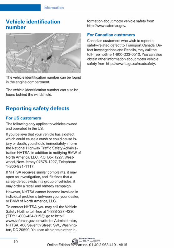
Vehicle identificationnumber
The vehicle identification number can be foundin the engine compartment.
The vehicle identification number can also befound behind the windshield.
Reporting safety defectsFor US customersThe following only applies to vehicles ownedand operated in the US.If you believe that your vehicle has a defectwhich could cause a crash or could cause in‐jury or death, you should immediately informthe National Highway Traffic Safety Adminis‐tration NHTSA, in addition to notifying BMW ofNorth America, LLC, P.O. Box 1227, West‐wood, New Jersey 07675-1227, Telephone1-800-831-1117.If NHTSA receives similar complaints, it mayopen an investigation, and if it finds that asafety defect exists in a group of vehicles, itmay order a recall and remedy campaign.However, NHTSA cannot become involved inindividual problems between you, your dealer,or BMW of North America, LLC.To contact NHTSA, you may call the VehicleSafety Hotline toll-free at 1-888-327-4236(TTY: 1-800-424-9153); go to http://www.safercar.gov; or write to: Administrator,NHTSA, 400 Seventh Street, SW., Washing‐ton, DC 20590. You can also obtain other in‐
formation about motor vehicle safety fromhttp://www.safercar.gov.
For Canadian customersCanadian customers who wish to report asafety-related defect to Transport Canada, De‐fect Investigations and Recalls, may call thetoll-free hotline 1-800-333-0510. You can alsoobtain other information about motor vehiclesafety from http://www.tc.gc.ca/roadsafety.
Seite 10
Information
10Online Edition for Part no. 01 40 2 963 410 - VI/15
Information Provided by:

Seite 11
Information
11Online Edition for Part no. 01 40 2 963 410 - VI/15
Information Provided by:
Online Edition for Part no. 01 40 2 963 410 - VI/15
Information Provided by:
At a glanceThese overviews of buttons, switches and
displays are intended to familiarize you with yourvehicle. You will also become quickly acquaintedwith the available control concepts and options.
Online Edition for Part no. 01 40 2 963 410 - VI/15
Information Provided by:
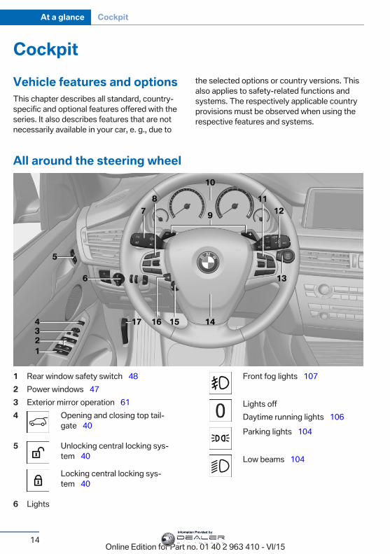
CockpitVehicle features and optionsThis chapter describes all standard, country-specific and optional features offered with theseries. It also describes features that are notnecessarily available in your car, e. g., due to
the selected options or country versions. Thisalso applies to safety-related functions andsystems. The respectively applicable countryprovisions must be observed when using therespective features and systems.
All around the steering wheel
1 Rear window safety switch 482 Power windows 473 Exterior mirror operation 614 Opening and closing top tail‐
gate 40
5 Unlocking central locking sys‐tem 40
Locking central locking sys‐tem 40
6 Lights
Front fog lights 107
Lights offDaytime running lights 106Parking lights 104
Low beams 104
Seite 14
At a glance Cockpit
14Online Edition for Part no. 01 40 2 963 410 - VI/15
Information Provided by:
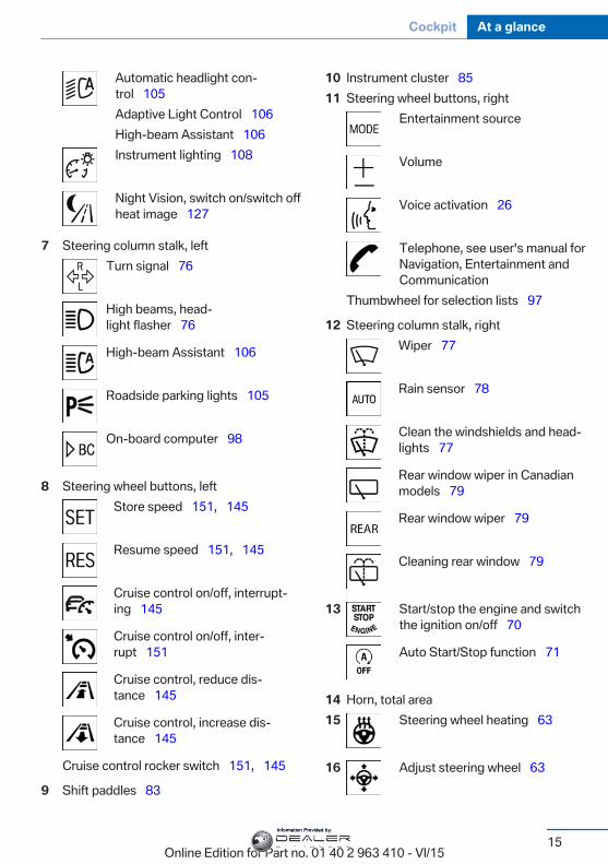
Automatic headlight con‐trol 105Adaptive Light Control 106High-beam Assistant 106Instrument lighting 108
Night Vision, switch on/switch offheat image 127
7 Steering column stalk, leftTurn signal 76
High beams, head‐light flasher 76
High-beam Assistant 106
Roadside parking lights 105
On-board computer 98
8 Steering wheel buttons, leftStore speed 151, 145
Resume speed 151, 145
Cruise control on/off, interrupt‐ing 145
Cruise control on/off, inter‐rupt 151
Cruise control, reduce dis‐tance 145
Cruise control, increase dis‐tance 145
Cruise control rocker switch 151, 145
9 Shift paddles 83
10 Instrument cluster 8511 Steering wheel buttons, right
Entertainment source
Volume
Voice activation 26
Telephone, see user's manual forNavigation, Entertainment andCommunication
Thumbwheel for selection lists 97
12 Steering column stalk, rightWiper 77
Rain sensor 78
Clean the windshields and head‐lights 77
Rear window wiper in Canadianmodels 79
Rear window wiper 79
Cleaning rear window 79
13 Start/stop the engine and switchthe ignition on/off 70
Auto Start/Stop function 71
14 Horn, total area15 Steering wheel heating 63
16 Adjust steering wheel 63
Seite 15
Cockpit At a glance
15Online Edition for Part no. 01 40 2 963 410 - VI/15
Information Provided by:
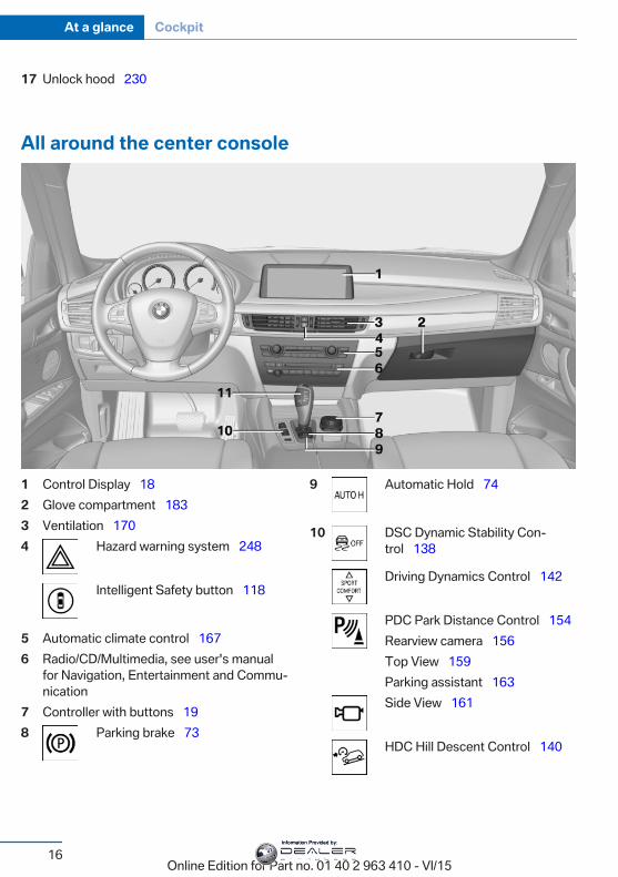
17 Unlock hood 230
All around the center console
1 Control Display 182 Glove compartment 1833 Ventilation 1704 Hazard warning system 248
Intelligent Safety button 118
5 Automatic climate control 1676 Radio/CD/Multimedia, see user's manual
for Navigation, Entertainment and Commu‐nication
7 Controller with buttons 198 Parking brake 73
9 Automatic Hold 74
10 DSC Dynamic Stability Con‐trol 138
Driving Dynamics Control 142
PDC Park Distance Control 154Rearview camera 156Top View 159Parking assistant 163Side View 161
HDC Hill Descent Control 140
Seite 16
At a glance Cockpit
16Online Edition for Part no. 01 40 2 963 410 - VI/15
Information Provided by:
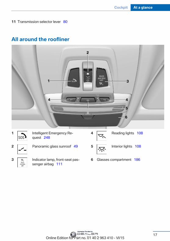
11 Transmission selector lever 80
All around the roofliner
1 Intelligent Emergency Re‐quest 248
2 Panoramic glass sunroof 49
3 Indicator lamp, front-seat pas‐senger airbag 111
4 Reading lights 108
5 Interior lights 108
6 Glasses compartment 186
Seite 17
Cockpit At a glance
17Online Edition for Part no. 01 40 2 963 410 - VI/15
Information Provided by:
iDriveVehicle features and optionsThis chapter describes all standard, country-specific and optional features offered with theseries. It also describes features that are notnecessarily available in your car, e. g., due tothe selected options or country versions. Thisalso applies to safety-related functions andsystems. The respectively applicable countryprovisions must be observed when using therespective features and systems.
The conceptThe iDrive combines the functions of manyswitches. Thus, these functions can be oper‐ated from a central location.
WARNINGOperating the integrated information
system and communication devices while driv‐ing can distract from traffic. It is possible tolose control of the vehicle. There is risk of anaccident. Only use the systems or deviceswhen the traffic situation allows. If necessarystop and use the systems and devices whilethe vehicle is stationary.◀
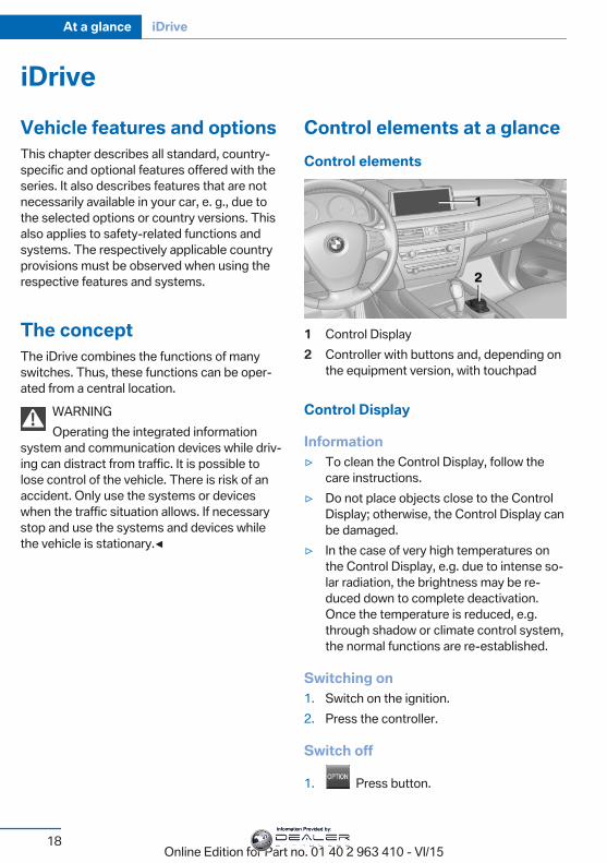
Control elements at a glanceControl elements
1 Control Display2 Controller with buttons and, depending on
the equipment version, with touchpad
Control Display
Information▷ To clean the Control Display, follow the
care instructions.▷ Do not place objects close to the Control
Display; otherwise, the Control Display canbe damaged.
▷ In the case of very high temperatures onthe Control Display, e.g. due to intense so‐lar radiation, the brightness may be re‐duced down to complete deactivation.Once the temperature is reduced, e.g.through shadow or climate control system,the normal functions are re-established.
Switching on1. Switch on the ignition.2. Press the controller.
Switch off
1. Press button.
Seite 18
At a glance iDrive
18Online Edition for Part no. 01 40 2 963 410 - VI/15
Information Provided by:
2. "Turn off control display"
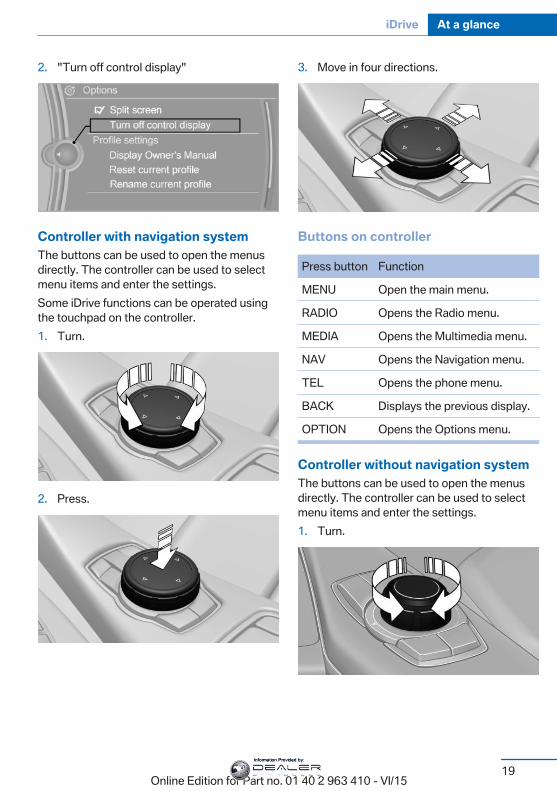
Controller with navigation systemThe buttons can be used to open the menusdirectly. The controller can be used to selectmenu items and enter the settings.Some iDrive functions can be operated usingthe touchpad on the controller.1. Turn.
2. Press.
3. Move in four directions.
Buttons on controller
Press button Function
MENU Open the main menu.
RADIO Opens the Radio menu.
MEDIA Opens the Multimedia menu.
NAV Opens the Navigation menu.
TEL Opens the phone menu.
BACK Displays the previous display.
OPTION Opens the Options menu.
Controller without navigation systemThe buttons can be used to open the menusdirectly. The controller can be used to selectmenu items and enter the settings.1. Turn.
Seite 19
iDrive At a glance
19Online Edition for Part no. 01 40 2 963 410 - VI/15
Information Provided by:
2. Press.
3. Move in two directions.
Buttons on controller
Press button Function
MENU Open the main menu.
Audio Open audio menu last listenedto, switch between audio me‐nus.
TEL Opens the phone menu.
BACK Open previous panel.
OPTION Opens the Options menu.
Operating conceptOpening the main menu
Press button.
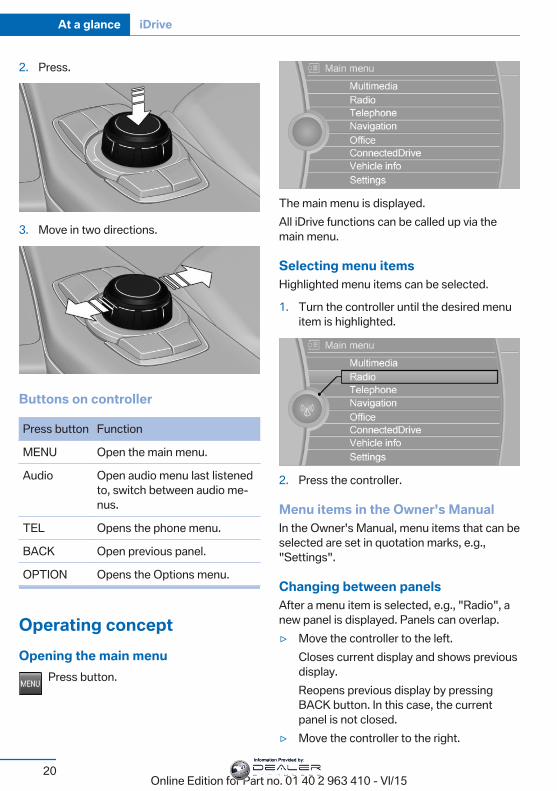
The main menu is displayed.All iDrive functions can be called up via themain menu.
Selecting menu itemsHighlighted menu items can be selected.
1. Turn the controller until the desired menuitem is highlighted.
2. Press the controller.
Menu items in the Owner's ManualIn the Owner's Manual, menu items that can beselected are set in quotation marks, e.g.,"Settings".
Changing between panelsAfter a menu item is selected, e.g., "Radio", anew panel is displayed. Panels can overlap.▷ Move the controller to the left.
Closes current display and shows previousdisplay.Reopens previous display by pressingBACK button. In this case, the currentpanel is not closed.
▷ Move the controller to the right.
Seite 20
At a glance iDrive
20Online Edition for Part no. 01 40 2 963 410 - VI/15
Information Provided by:
Opens new display on top of previousscreen.
White arrows pointing to the left or right indi‐cate that additional panels can be opened.
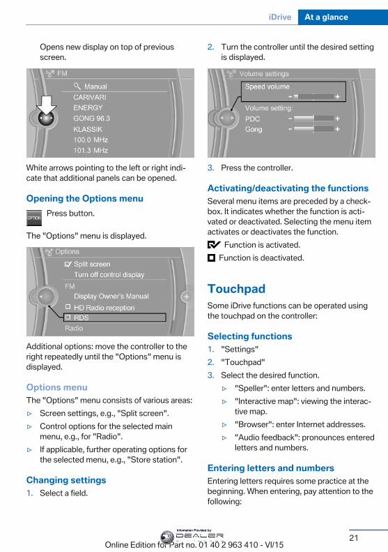
Opening the Options menuPress button.
The "Options" menu is displayed.
Additional options: move the controller to theright repeatedly until the "Options" menu isdisplayed.
Options menuThe "Options" menu consists of various areas:▷ Screen settings, e.g., "Split screen".▷ Control options for the selected main
menu, e.g., for "Radio".▷ If applicable, further operating options for
the selected menu, e.g., "Store station".
Changing settings1. Select a field.
2. Turn the controller until the desired settingis displayed.
3. Press the controller.
Activating/deactivating the functionsSeveral menu items are preceded by a check‐box. It indicates whether the function is acti‐vated or deactivated. Selecting the menu itemactivates or deactivates the function.
Function is activated. Function is deactivated.
TouchpadSome iDrive functions can be operated usingthe touchpad on the controller:
Selecting functions1. "Settings"2. "Touchpad"3. Select the desired function.
▷ "Speller": enter letters and numbers.▷ "Interactive map": viewing the interac‐
tive map.▷ "Browser": enter Internet addresses.▷ "Audio feedback": pronounces entered
letters and numbers.
Entering letters and numbersEntering letters requires some practice at thebeginning. When entering, pay attention to thefollowing:
Seite 21
iDrive At a glance
21Online Edition for Part no. 01 40 2 963 410 - VI/15
Information Provided by:
▷ The system recognizes capital and lowercase letters. For the input of upper/lowercase letters and numbers, it may be neces‐sary to switch to the corresponding inputmode, e.g. when upper and lower case let‐ters are written the same way. Switchingbetween cases, numbers and letters, referto page 25.
▷ Enter characters as they are displayed onthe Control Display.
▷ Always enter associated characters, suchas accents or periods so that the letter canbe clearly recognized. Possible input de‐pends on the set language. Where neces‐sary, enter special characters via the con‐troller.
▷ To delete a character, slide to the left onthe touchpad.
▷ To enter a blank space, slide to the right inthe center of the touchpad.
▷ To enter a hyphen, slide to the right in theupper area of the touchpad.
▷ To enter an underscore, swipe to the rightin the lower area of the touchpad.
Using interactive map and InternetVia touch-pad move the interactive map in thenavigation system and Internet sites.
Function Controls
Move interactive map orInternet sites.
Swipe into re‐spective direc‐tion.
Enlarge/shrink interactivemap or Internet sites.
Drag in or out onthe touchpad withfingers.
Display the menu or opena link in the Internet.
Tap once.
Changing settingsYou may change control display settings viatouchpad. Swipe left or right accordingly.
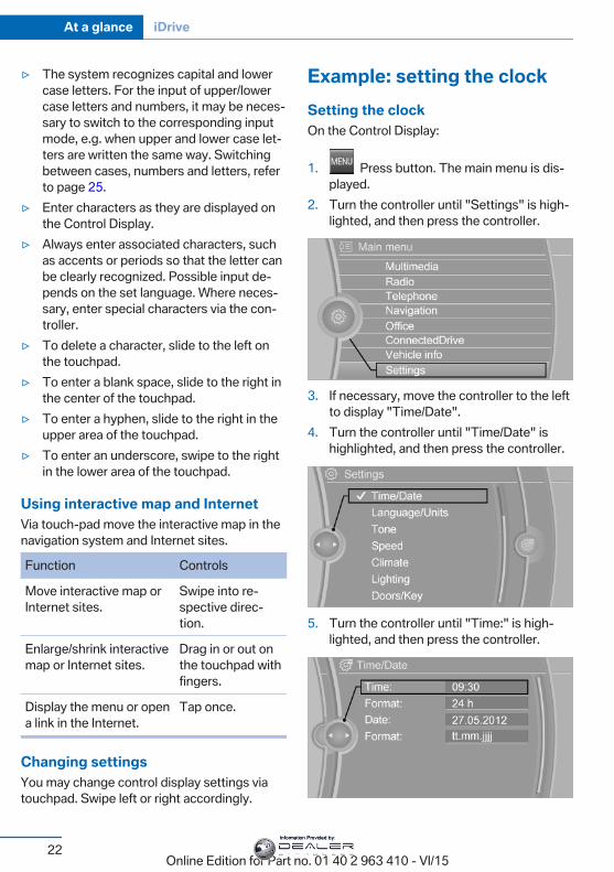
Example: setting the clockSetting the clockOn the Control Display:
1. Press button. The main menu is dis‐played.
2. Turn the controller until "Settings" is high‐lighted, and then press the controller.
3. If necessary, move the controller to the leftto display "Time/Date".
4. Turn the controller until "Time/Date" ishighlighted, and then press the controller.
5. Turn the controller until "Time:" is high‐lighted, and then press the controller.
Seite 22
At a glance iDrive
22Online Edition for Part no. 01 40 2 963 410 - VI/15
Information Provided by:
6. Turn the controller to set the hours andpress the controller.
7. Turn the controller to set the minutes andpress the controller.
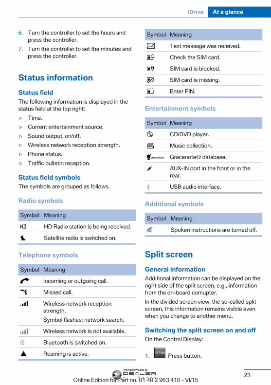
Status informationStatus fieldThe following information is displayed in thestatus field at the top right:▷ Time.▷ Current entertainment source.▷ Sound output, on/off.▷ Wireless network reception strength.▷ Phone status.▷ Traffic bulletin reception.
Status field symbolsThe symbols are grouped as follows.
Radio symbols
Symbol Meaning
HD Radio station is being received.
Satellite radio is switched on.
Telephone symbols
Symbol Meaning
Incoming or outgoing call.
Missed call.
Wireless network receptionstrength.Symbol flashes: network search.
Wireless network is not available.
Bluetooth is switched on.
Roaming is active.
Symbol Meaning
Text message was received.
Check the SIM card.
SIM card is blocked.
SIM card is missing.
Enter PIN.
Entertainment symbols
Symbol Meaning
CD/DVD player.
Music collection.
Gracenote® database.
AUX-IN port in the front or in therear.
USB audio interface.
Additional symbols
Symbol Meaning
Spoken instructions are turned off.
Split screenGeneral informationAdditional information can be displayed on theright side of the split screen, e.g., informationfrom the on-board comupter.In the divided screen view, the so-called splitscreen, this information remains visible evenwhen you change to another menu.
Switching the split screen on and offOn the Control Display:
1. Press button.
Seite 23
iDrive At a glance
23Online Edition for Part no. 01 40 2 963 410 - VI/15
Information Provided by:
2. "Split screen"
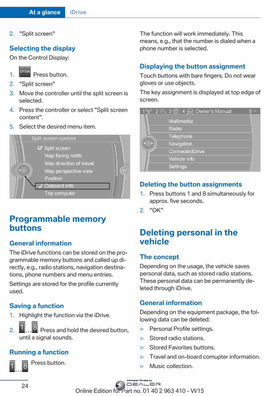
Selecting the displayOn the Control Display:
1. Press button.2. "Split screen"3. Move the controller until the split screen is
selected.4. Press the controller or select "Split screen
content".5. Select the desired menu item.
Programmable memorybuttonsGeneral informationThe iDrive functions can be stored on the pro‐grammable memory buttons and called up di‐rectly, e.g., radio stations, navigation destina‐tions, phone numbers and menu entries.Settings are stored for the profile currentlyused.
Saving a function1. Highlight the function via the iDrive.
2. Press and hold the desired button,until a signal sounds.
Running a functionPress button.
The function will work immediately. Thismeans, e.g., that the number is dialed when aphone number is selected.
Displaying the button assignmentTouch buttons with bare fingers. Do not weargloves or use objects.The key assignment is displayed at top edge ofscreen.
Deleting the button assignments1. Press buttons 1 and 8 simultaneously for
approx. five seconds.2. "OK"
Deleting personal in thevehicleThe conceptDepending on the usage, the vehicle savespersonal data, such as stored radio stations.These personal data can be permanently de‐leted through iDrive.
General informationDepending on the equipment package, the fol‐lowing data can be deleted:▷ Personal Profile settings.▷ Stored radio stations.▷ Stored Favorites buttons.▷ Travel and on-board comupter information.▷ Music collection.
Seite 24
At a glance iDrive
24Online Edition for Part no. 01 40 2 963 410 - VI/15
Information Provided by:
▷ Navigation, e.g. stored destinations.▷ Phone book.▷ Online data, e.g. Favorites, cookies.▷ Voice notes▷ Login accounts.▷ RemoteApp smartphone tethering.Altogether, the deletion of the data can take upto 30 minutes.
Functional requirementData can only be deleted while stationary.
Deleting dataHeed and follow the instructions on the Con‐trol Display.
1. Switch on the ignition.2. "Settings"3. Open "Options".4. "Delete personal data"5. "Continue"6. "OK"
Entering letters and numbersGeneral informationOn the Control Display:
1. Turn the controller: select letters or num‐bers.
2. Select additional letters or numbers ifneeded.
3. "OK": confirm the entry.
Symbol Function
Press the controller: delete the let‐ter or number.
Press the controller for an extendedperiod: delete all letters or numbers.
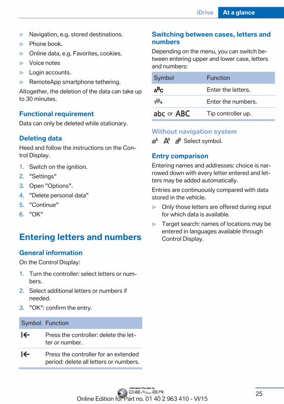
Switching between cases, letters andnumbersDepending on the menu, you can switch be‐tween entering upper and lower case, lettersand numbers:
Symbol Function
Enter the letters.
Enter the numbers.
or Tip controller up.
Without navigation system Select symbol.
Entry comparisonEntering names and addresses: choice is nar‐rowed down with every letter entered and let‐ters may be added automatically.Entries are continuously compared with datastored in the vehicle.▷ Only those letters are offered during input
for which data is available.▷ Target search: names of locations may be
entered in languages available throughControl Display.
Seite 25
iDrive At a glance
25Online Edition for Part no. 01 40 2 963 410 - VI/15
Information Provided by:
Voice activation systemVehicle features and optionsThis chapter describes all standard, country-specific and optional features offered with theseries. It also describes features that are notnecessarily available in your car, e. g., due tothe selected options or country versions. Thisalso applies to safety-related functions andsystems. The respectively applicable countryprovisions must be observed when using therespective features and systems.
The concept▷ Most functions displayed on the Control
Display can be operated by voice com‐mands via the voice activation system. Thesystem supports you with announcementsduring input.
▷ Functions that can only be used when thevehicle is stationary cannot be used via thevoice activation system.
▷ The system uses a special microphone onthe driver's side.
▷ ›...‹ Verbal instructions in the Owner'sManual to use with the voice activationsystem.
RequirementsVia the Control Display, set a language that isalso supported by the voice activation systemso that the spoken commands can be identi‐fied.Set the language, refer to page 101.
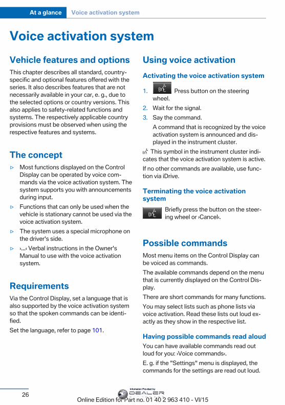
Using voice activationActivating the voice activation system
1. Press button on the steeringwheel.
2. Wait for the signal.3. Say the command.
A command that is recognized by the voiceactivation system is announced and dis‐played in the instrument cluster.
This symbol in the instrument cluster indi‐cates that the voice activation system is active.If no other commands are available, use func‐tion via iDrive.
Terminating the voice activationsystem
Briefly press the button on the steer‐ing wheel or ›Cancel‹.
Possible commandsMost menu items on the Control Display canbe voiced as commands.The available commands depend on the menuthat is currently displayed on the Control Dis‐play.There are short commands for many functions.You may select lists such as phone lists viavoice activation. Read these lists out loud ex‐actly as they show in the respective list.
Having possible commands read aloudYou can have available commands read outloud for you: ›Voice commands‹.E. g. if the "Settings" menu is displayed, thecommands for the settings are read out loud.
Seite 26
At a glance Voice activation system
26Online Edition for Part no. 01 40 2 963 410 - VI/15
Information Provided by:
Executing functions using shortcommandsExecute functions on the main menu via shortcommands. It almost doesn't matter whichmenu item is selected, e.g., ›Vehicle status‹.List of short commands for the voice activationsystem, see Navigation, Entertainment, Com‐munication Owner's Manual.
Help dialog for the voice activationsystemCalling up help dialog: ›Help‹.Additional commands for the help dialog:▷ ›Help with examples‹: announces informa‐
tion about the current operating optionsand the most important commands forthem.
▷ ›Help with voice activation‹: informationabout the principle of operation for thevoice activation system is announced.
One example: open the tonesettingsVia the main menuThe commands of the menu items are spokenjust as they are selected via the controller.
1. Turn on the Entertainment sound output ifneeded.
2. Press button on the steeringwheel.
3. ›Radio‹4. ›Tone‹
Via short commandThe desired tone settings can also be startedvia a short command.
1. Turn on the Entertainment sound output ifneeded.
2. Press button on the steeringwheel.
3. ›Tone‹
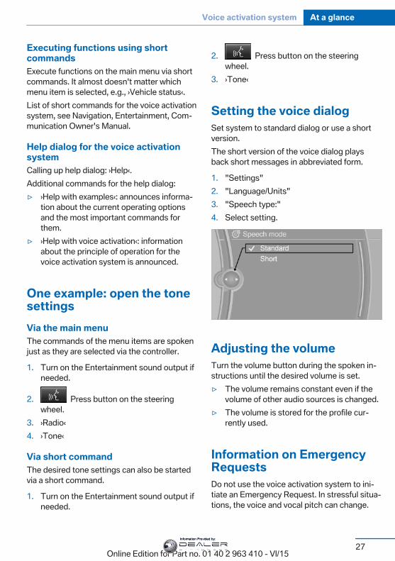
Setting the voice dialogSet system to standard dialog or use a shortversion.The short version of the voice dialog playsback short messages in abbreviated form.
1. "Settings"2. "Language/Units"3. "Speech type:"4. Select setting.
Adjusting the volumeTurn the volume button during the spoken in‐structions until the desired volume is set.▷ The volume remains constant even if the
volume of other audio sources is changed.▷ The volume is stored for the profile cur‐
rently used.
Information on EmergencyRequestsDo not use the voice activation system to ini‐tiate an Emergency Request. In stressful situa‐tions, the voice and vocal pitch can change.
Seite 27
Voice activation system At a glance
27Online Edition for Part no. 01 40 2 963 410 - VI/15
Information Provided by:
This can unnecessarily delay the establish‐ment of a phone connection.Instead, use the SOS button, refer topage 248, close to the interior mirror.
Environmental conditions▷ Say the commands, numbers, and letters
smoothly and with normal volume, empha‐sis, and speed.
▷ Always say commands in the language ofthe voice activation system.
▷ Keep the doors, windows, and glass sun‐roof closed to prevent noise interference.
▷ Avoid making other noise in the vehiclewhile speaking.
Seite 28
At a glance Voice activation system
28Online Edition for Part no. 01 40 2 963 410 - VI/15
Information Provided by:
Integrated Owner's Manual in the vehicleVehicle features and optionsThis chapter describes all standard, country-specific and optional features offered with theseries. It also describes features that are notnecessarily available in your car, e. g., due tothe selected options or country versions. Thisalso applies to safety-related functions andsystems. The respectively applicable countryprovisions must be observed when using therespective features and systems.
Integrated Owner's Manualin the vehicleThe Integrated Owner's Manual can be dis‐played on the Control Display. It specificallydescribes features and functions found in thevehicle.
Components of the IntegratedOwner's ManualThe Integrated Owner's Manual consists ofthree parts, which offer various levels of infor‐mation or possible access.
Quick Reference GuideThe Quick Reference Guide provides informa‐tion how to operate the car, how to use basicvehicle functions or what to do in case of abreakdown. This information can also be dis‐played while driving.
Search by imagesImage search provides information and de‐scriptions. This is helpful when the terminol‐ogy for a feature is not at hand.
Owner's ManualSearch for information and descriptions by en‐tering terms selected from the index.
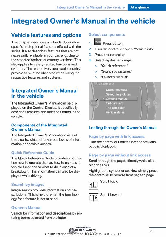
Select components
1. Press button.2. Turn the controller: open "Vehicle info".3. Press the controller.4. Selecting desired range:
▷ "Quick reference"▷ "Search by pictures"▷ "Owner's Manual"
Leafing through the Owner's Manual
Page by page with link accessTurn the controller until the next or previouspage is displayed.
Page by page without link accessScroll through the pages directly while skip‐ping the links.Highlight the symbol once. Now simply pressthe controller to browse from page to page.
Scroll back.
Scroll forward.
Seite 29
Integrated Owner's Manual in the vehicle At a glance
29Online Edition for Part no. 01 40 2 963 410 - VI/15
Information Provided by:
Context help - Owner's Manual to thetemporarily selected functionYou may open the relevant information di‐rectly.
Opening via the iDriveTo move directly from the application on theControl Display to the Options menu:
1. Press button or move the controllerto the right repeatedly until the "Options"menu is displayed.
2. "Display Owner's Manual"
Opening when a Check Controlmessage is displayedDirectly from the Check Control message onthe Control Display:"Display Owner's Manual"
Changing between a function and theOwner's ManualTo switch from a function, e. g., radio, to theOwner's Manual on the Control Display and toalternate between the two displays:
1. Press button or move the controllerto the right repeatedly until the "Options"menu is displayed.
2. "Display Owner's Manual"3. Select the desired page in the Owner's
Manual.
4. Press button again to return to lastdisplayed function.
5. Press button to return to the page ofthe Owner's Manual displayed last.
To alternate permanently between the last dis‐played function and the Owner's Manual re‐peat steps 4 & 5. Opens a new display everytime.
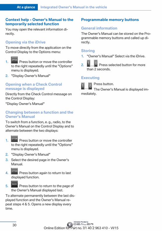
Programmable memory buttons
General informationThe Owner's Manual can be stored on the Pro‐grammable memory buttons and called up di‐rectly.
Storing1. "Owner's Manual" Select via the iDrive.
2. Press selected button for morethan 2 seconds.
ExecutingPress button.The Owner's Manual is displayed im‐
mediately.
Seite 30
At a glance Integrated Owner's Manual in the vehicle
30Online Edition for Part no. 01 40 2 963 410 - VI/15
Information Provided by:

Seite 31
Integrated Owner's Manual in the vehicle At a glance
31Online Edition for Part no. 01 40 2 963 410 - VI/15
Information Provided by:
Online Edition for Part no. 01 40 2 963 410 - VI/15
Information Provided by:
ControlsThis chapter is intended to provide you with
information that will give you complete control ofyour vehicle. All features and accessories thatare useful for driving and your safety, comfort
and convenience are described here.
Online Edition for Part no. 01 40 2 963 410 - VI/15
Information Provided by:
Opening and closingVehicle features and optionsThis chapter describes all standard, country-specific and optional features offered with theseries. It also describes features that are notnecessarily available in your car, e. g., due tothe selected options or country versions. Thisalso applies to safety-related functions andsystems. The respectively applicable countryprovisions must be observed when using therespective features and systems.
Remote control/keyGeneral informationThe vehicle is supplied with two remote con‐trols with integrated key.Every remote control holds a replaceable bat‐tery.You may set the key functions depending onthe optional features and country-specific ver‐sion. For Settings, refer to page 44.The vehicle stores personal settings for everyremote control. Personal Profile, refer topage 35.The remote controls hold information on re‐quired maintenance. Service data in the re‐mote control, refer to page 238
Overview
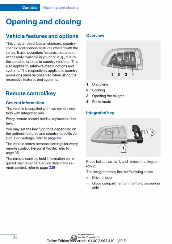
1 Unlocking2 Locking3 Opening the tailgate4 Panic mode
Integrated key
Press button, arrow 1, and remove the key, ar‐row 2.The integrated key fits the following locks:▷ Driver's door.▷ Glove compartment on the front passenger
side.
Seite 34
Controls Opening and closing
34Online Edition for Part no. 01 40 2 963 410 - VI/15
Information Provided by:

Replacing the battery
1. Remove integrated key from remote con‐trol.
2. Raise the cover of the battery compart‐ment, arrow 1.
3. Remove the cover of the battery compart‐ment, arrow 2.
4. Insert a battery of the same type with thepositive side facing up.
5. Press the cover closed.Have old battery disposed of by adealer’s service center or anotherqualified service center or repair shop
or take it to a collection point.
New remote controlsNew remote controls are available from adealer’s service center or another qualifiedservice center or repair shop.
Loss of the remote controlsThe lost remote control can be blocked by adealer’s service center or another qualifiedservice center or repair shop.
Emergency detection of remotecontrolIt is possible to switch on the ignition or startthe engine in situations such as the following:▷ Interference of radio transmission to re‐
mote control by external sources e.g., byradio masts.
▷ Empty battery in remote control.
▷ Interference from radio transmissionsthrough mobile devices in close proximityto remote control.
▷ Interference of radio transmission bycharger while charging items such as mo‐bile devices in the vehicle.
A Check Control message is displayed if an at‐tempt is made to switch on the ignition or startthe engine.
Starting the engine with emergencydetection of the remote control
If a respective Check Control message ap‐pears, hold the remote control with its backagainst the marked area on the steering col‐umn. The tailgate button on the remote controlshould be at the same height as the markedarea. Press the Start/Stop button within10 seconds while pressing the brake pedal.If the remote control is not recognized: slightlychange the height position of the remote con‐trol and repeat the procedure.
Personal ProfileThe conceptPersonal Profile provides three profiles, usingwhich personal vehicle settings can be stored.Every remote control has one of these profilesassigned.If the vehicle is unlocked using a remote con‐trol, the assigned personal profile will be acti‐vated. All settings stored in the profile are au‐tomatically applied.
Seite 35
Opening and closing Controls
35Online Edition for Part no. 01 40 2 963 410 - VI/15
Information Provided by:
If several drivers use their own remote control,the vehicle will adjust the personal settingsduring unlocking. These settings are also re‐stored, if the vehicle has been used in themeantime by a person with a different remotecontrol.Changes to the settings are automaticallysaved in the personal profile.Three personal profiles and a guest profile canbe created.
AdjustingThe settings for the following systems andfunctions are saved in the active profile. Thescope of storable settings is country- andequipment-dependable.▷ Unlocking and locking.▷ Lights.▷ Climate control.▷ Radio.▷ Instrument cluster.▷ Programmable memory buttons.▷ Volumes, tone.▷ Control Display.▷ Navigation.▷ Park Distance Control PDC.▷ Rearview camera▷ Side View.▷ Head-up Display.▷ Driving Dynamics Control.▷ Driver's seat position, exterior mirror posi‐
tion, steering wheel position.▷ Cruise control.▷ Intelligent Safety.▷ Active Blind Spot Detection.▷ Night vision.
Profile management
Opening profilesRegardless of the remote control in use a dif‐ferent profile may be activated.About iDrive:
1. "Settings"2. "Profiles"3. Select a profile.▷ All settings stored in the called-up profile
are automatically applied.▷ The called-up profile is assigned to the re‐
mote control being used at the time.▷ If the profile is already assigned to a differ‐
ent remote control, this profile will apply toboth remote controls. It cannot be differen‐tiated anymore between the settings forthe two remote controls.
Renaming profilesA personal name can be assigned to every pro‐file to avoid confusion between the profiles.On the Control Display:
1. "Settings"2. "Profiles"3. Open "Options".4. "Rename current profile"
Resetting profilesThe settings of the active profile are reset totheir default values.On the Control Display:
1. "Settings"2. "Profiles"3. Open "Options".4. "Reset current profile"
Exporting profilesMost settings of the active profile can be ex‐ported.
Seite 36
Controls Opening and closing
36Online Edition for Part no. 01 40 2 963 410 - VI/15
Information Provided by:
This can be helpful for securing and retrievingpersonal settings, before delivering the vehicleto a workshop, e.g. Profiles can be taken to an‐other vehicle equipped with the Personal Pro‐file function.The following export options are available:▷ Via BMW Online.▷ Via the USB port to a USB device.
Popular file systems for USB devices aresupported. FAT32 and exFAT are the rec‐ommended formats for profile export.Other formats may not support the export.
Export is made via the USB port to a USB de‐vice. Popular file systems for USB devices aresupported. FAT32 and exFAT are the recom‐mended formats for profile export. Other for‐mats may not support the export.On the Control Display:
1. "Settings"2. "Profiles"3. "Export profile"4. BMW Online: "BMW Online"
USB interface: "USB device"
Importing profilesProfiles exported via BMW Online can also beimported via BMW Online.Profiles stored on a USB device can be im‐ported via the USB interface.Existing settings are overwritten with the im‐ported profile.On the Control Display:
1. "Settings"2. "Profiles"3. "Import profile"4. BMW Online: "BMW Online"
USB interface: "USB device"
Using the guest profileThe guest profile is for individual settings thatare saved in none of the three personal pro‐files.This can be useful for drivers who are usingthe vehicle temporarily and do not have theirown profile.On the Control Display:
1. "Settings"2. "Profiles"3. "Guest"The guest profile cannot be renamed. It is notassigned to the current remote control.
Display profile list during startThe profile list can be displayed during eachstart to select the desired profile.On the Control Display:
1. "Settings"2. "Profiles"3. Open "Options".4. "Display user list at startup"
Using the remote controlInformation
WARNINGPeople or animals in the vehicle can lock
the doors from the inside and lock themselvesin. The vehicle can then not be opened fromthe outside. There is risk of injuries. Take theremote control along so that the vehicle can beopened from the outside.◀
UnlockingPress button on the remote control.
Depending on the settings, refer to page 44,the following access points are unlocked.
Seite 37
Opening and closing Controls
37Online Edition for Part no. 01 40 2 963 410 - VI/15
Information Provided by:
▷ Driver's door and fuel filler flap.▷ All doors, tailgate, and fuel filler flap.In addition, the following functions are exe‐cuted:▷ The interior lights are switched on, when it
is dark outside, the courtesy lamps are alsoswitched on. This function is not available,if the interior lamps were switched off man‐ually.
▷ The welcome lamps are switched on, if thisfunction was activated.
▷ The alarm system, refer to page 45, isdisarmed.
Convenient openingPress and hold this button on the re‐mote control after unlocking.
The windows and the glass sunroof areopened, as long as the button on the remotecontrol is pressed.
LockingWARNINGUnlocking from the inside is only possi‐
ble with special knowledge.If people must spend a longer time in the vehi‐cle while it is very hot or cold outside, there isrisk of injuries or danger to life. Do not lock thevehicle from the outside when there are peoplein it.◀
The driver's door must be closed.Press button on the remote control.
All doors, the tailgate, and the fuel filler flap arebeing locked.The alarm system, refer to page 45, is armed.
Switching on interior lights andcourtesy lights
Press button on the remote control withthe vehicle locked.
The courtesy lamps are only switched on whenit is dark outside. This function is not available,if the interior lamps were switched off man‐ually.If the button is pressed again within 10 sec‐onds after vehicle was locked, the interior mo‐tion sensor and tilt alarm sensor of the anti-theft warning system, refer to page 47, areturned off. After locking, wait 10 seconds be‐fore pressing the button again.
Panic modeYou can trigger the alarm system if you findyourself in a dangerous situation.
Press button on the remote control forat least 3 seconds.
To switch off the alarm: press any button.
Opening the tailgateCAUTIONThe tailgate swings back and up when it
opens. There is risk of property damage. Makesure that the area of movement of the tailgateis clear during opening and closing.◀
To avoid locking it into the vehicle, do notplace the remote control in the cargo area.
Press button on the remote control forapprox. 1 second and release.
The closed tailgate is automatically opened,whether or not the vehicle is locked or un‐locked.Depending on the features and the countryversion, it is also possible to have door un‐locked. Create the settings, refer to page 44.The tailgate cannot be opened with the remotecontrol while a trailer is being towed.
Seite 38
Controls Opening and closing
38Online Edition for Part no. 01 40 2 963 410 - VI/15
Information Provided by:
If the doors were not unlocked, the tailgate islocked again as soon as it closes. Take the re‐mote control with you and do not leave it in thecargo area; otherwise, the remote control islocked inside the vehicle when the tailgate isclosed.
CAUTIONSharp-edged or pointed objects can hit
the rear window and heat conductors whiledriving. There is risk of property damage.Cover the edges and ensure that pointed ob‐jects do not hit the rear window.◀
MalfunctionRemote control detection by the vehicle canamong others be malfunctioning under the fol‐lowing circumstances:▷ The battery of the remote control is dis‐
charged. Replace the battery, refer topage 35.
▷ Interference of the radio connection fromtransmission towers or other equipmentwith high transmit power.
▷ Shielding of the remote control due tometal objects.
▷ Interference of the radio connection frommobile phones or other electronic devicesin direct proximity.
Do not transport the remote control togetherwith metal objects or electronic devices.In the case of interference, the vehicle can alsobe unlocked and locked from the outside with‐out remote control, refer to page 39.
For US owners onlyThe transmitter and receiver units comply withpart 15 of the FCC/Federal CommunicationCommission regulations. Operation is gov‐erned by the following:FCC ID:▷ LX8766S.▷ LX8766E.
▷ LX8CAS.▷ LX8CAS2.▷ MYTCAS4.Compliance statement:This device complies with part 15 of the FCCRules. Operation is subject to the followingtwo conditions:▷ This device may not cause harmful inter‐
ference, and▷ this device must accept any interference
received, including interference that maycause undesired operation.
Any unauthorized modifications or changes tothese devices could void the user's authority tooperate this equipment.
Without remote controlFrom the outside
WARNINGUnlocking from the inside is only possi‐
ble with special knowledge.If people must spend a longer time in the vehi‐cle while it is very hot or cold outside, there isrisk of injuries or danger to life. Do not lock thevehicle from the outside when there are peoplein it.◀
CAUTIONThe door lock is permanently joined with
the door. The door handle can be moved.When pulling the door handle with theintegrated key inserted, paint or key can bedamaged. There is risk of property damage.Remove the integrated key before pulling theoutside door handle.◀
Unlock or lock the driver's door via the doorlock using the integrated key, refer to page 34.The other doors must be unlocked or lockedfrom the inside.
1. Remove lid on the door lock.
Seite 39
Opening and closing Controls
39Online Edition for Part no. 01 40 2 963 410 - VI/15
Information Provided by:
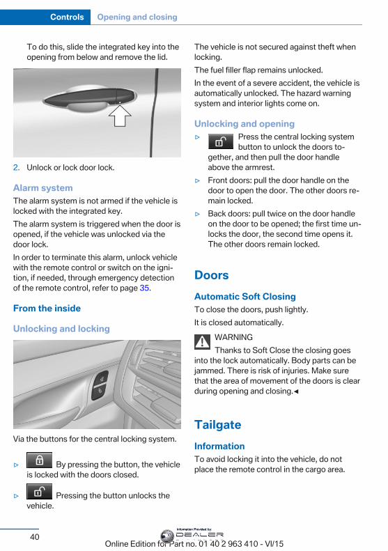
To do this, slide the integrated key into theopening from below and remove the lid.
2. Unlock or lock door lock.
Alarm systemThe alarm system is not armed if the vehicle islocked with the integrated key.The alarm system is triggered when the door isopened, if the vehicle was unlocked via thedoor lock.In order to terminate this alarm, unlock vehiclewith the remote control or switch on the igni‐tion, if needed, through emergency detectionof the remote control, refer to page 35.
From the inside
Unlocking and locking
Via the buttons for the central locking system.
▷ By pressing the button, the vehicleis locked with the doors closed.
▷ Pressing the button unlocks thevehicle.
The vehicle is not secured against theft whenlocking.The fuel filler flap remains unlocked.In the event of a severe accident, the vehicle isautomatically unlocked. The hazard warningsystem and interior lights come on.
Unlocking and opening▷ Press the central locking system
button to unlock the doors to‐gether, and then pull the door handleabove the armrest.
▷ Front doors: pull the door handle on thedoor to open the door. The other doors re‐main locked.
▷ Back doors: pull twice on the door handleon the door to be opened; the first time un‐locks the door, the second time opens it.The other doors remain locked.
DoorsAutomatic Soft ClosingTo close the doors, push lightly.It is closed automatically.
WARNINGThanks to Soft Close the closing goes
into the lock automatically. Body parts can bejammed. There is risk of injuries. Make surethat the area of movement of the doors is clearduring opening and closing.◀
TailgateInformationTo avoid locking it into the vehicle, do notplace the remote control in the cargo area.
Seite 40
Controls Opening and closing
40Online Edition for Part no. 01 40 2 963 410 - VI/15
Information Provided by:
Automatic tailgate operation
Adjusting the opening heightYou can set how far the tailgate should open.
CAUTIONThe tailgate swings back and up when it
opens. There is risk of property damage. Makesure that the area of movement of the tailgateis clear during opening and closing.◀
When adjusting the opening height, ensurethat there is a clearance of at least 4 in/10 cmabove the tailgate.
1. "Settings"2. "Tailgate"3. Turn the controller until the desired open‐
ing height is selected.
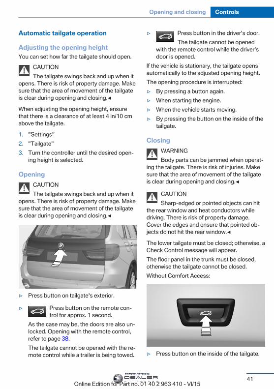
OpeningCAUTIONThe tailgate swings back and up when it
opens. There is risk of property damage. Makesure that the area of movement of the tailgateis clear during opening and closing.◀
▷ Press button on tailgate's exterior.
▷ Press button on the remote con‐trol for approx. 1 second.
As the case may be, the doors are also un‐locked. Opening with the remote control,refer to page 38.The tailgate cannot be opened with the re‐mote control while a trailer is being towed.
▷ Press button in the driver's door.The tailgate cannot be opened
with the remote control while the driver'sdoor is opened.
If the vehicle is stationary, the tailgate opensautomatically to the adjusted opening height.The opening procedure is interrupted:▷ By pressing a button again.▷ When starting the engine.▷ When the vehicle starts moving.▷ By pressing the button on the inside of the
tailgate.
ClosingWARNINGBody parts can be jammed when operat‐
ing the tailgate. There is risk of injuries. Makesure that the area of movement of the tailgateis clear during opening and closing.◀
CAUTIONSharp-edged or pointed objects can hit
the rear window and heat conductors whiledriving. There is risk of property damage.Cover the edges and ensure that pointed ob‐jects do not hit the rear window.◀
The lower tailgate must be closed; otherwise, aCheck Control message will appear.The floor panel in the trunk must be closed,otherwise the tailgate cannot be closed.Without Comfort Access:
▷ Press button on the inside of the tailgate.
Seite 41
Opening and closing Controls
41Online Edition for Part no. 01 40 2 963 410 - VI/15
Information Provided by:
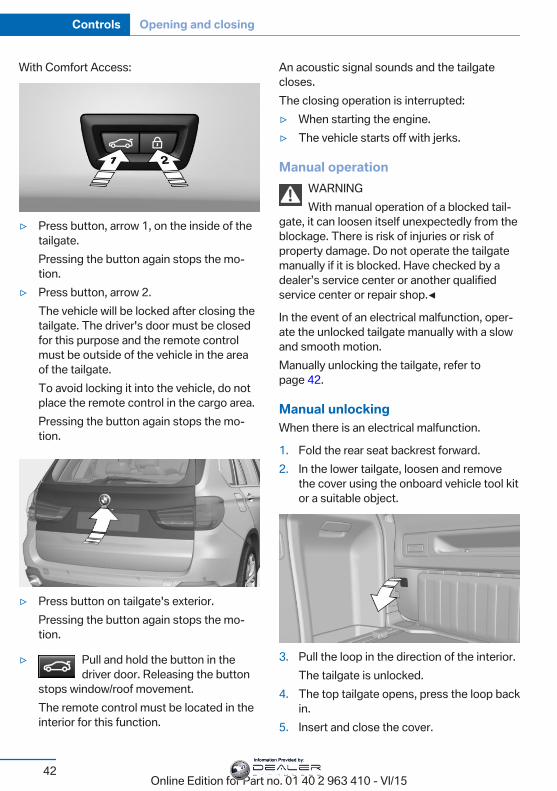
With Comfort Access:
▷ Press button, arrow 1, on the inside of thetailgate.Pressing the button again stops the mo‐tion.
▷ Press button, arrow 2.The vehicle will be locked after closing thetailgate. The driver's door must be closedfor this purpose and the remote controlmust be outside of the vehicle in the areaof the tailgate.To avoid locking it into the vehicle, do notplace the remote control in the cargo area.Pressing the button again stops the mo‐tion.
▷ Press button on tailgate's exterior.Pressing the button again stops the mo‐tion.
▷ Pull and hold the button in thedriver door. Releasing the button
stops window/roof movement.The remote control must be located in theinterior for this function.
An acoustic signal sounds and the tailgatecloses.The closing operation is interrupted:▷ When starting the engine.▷ The vehicle starts off with jerks.
Manual operationWARNINGWith manual operation of a blocked tail‐
gate, it can loosen itself unexpectedly from theblockage. There is risk of injuries or risk ofproperty damage. Do not operate the tailgatemanually if it is blocked. Have checked by adealer’s service center or another qualifiedservice center or repair shop.◀
In the event of an electrical malfunction, oper‐ate the unlocked tailgate manually with a slowand smooth motion.Manually unlocking the tailgate, refer topage 42.
Manual unlockingWhen there is an electrical malfunction.
1. Fold the rear seat backrest forward.2. In the lower tailgate, loosen and remove
the cover using the onboard vehicle tool kitor a suitable object.
3. Pull the loop in the direction of the interior.The tailgate is unlocked.
4. The top tailgate opens, press the loop backin.
5. Insert and close the cover.
Seite 42
Controls Opening and closing
42Online Edition for Part no. 01 40 2 963 410 - VI/15
Information Provided by:
The tailgate is locked again as soon as it isclosed.
Lower tailgate
Opening
Pull the lever and swing down the tailgate.The open tailgate can be loaded with up to550 lbs/250 kg.
ClosingSwing up the tailgate, and press it closed.
Comfort AccessThe conceptThe vehicle can be accessed without activat‐ing the remote control.All you need to do is to have the remote con‐trol with you, such as in your pants pocket.The vehicle automatically detects the remotecontrol when it is in close proximity or in thecar's interior.Comfort Access supports the following func‐tions:▷ Unlocking/locking of the vehicle.▷ Convenient closing.▷ Opening the tailgate individually▷ Start the engine.
InformationTo avoid locking it into the vehicle, do notplace the remote control in the cargo area.
Functional requirements▷ There are no external sources of interfer‐
ence nearby.▷ To lock the vehicle, the remote control
must be located outside of the vehicle nearthe doors.
▷ The next unlocking and locking cycle is notpossible until after approx. 2 seconds.
▷ The engine can only be started if the re‐mote control is in the vehicle.
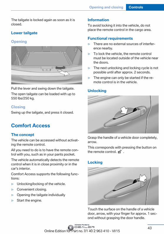
Unlocking
Grasp the handle of a vehicle door completely,arrow.This corresponds with pressing the button onthe remote control. .
Locking
Touch the surface on the handle of a vehicledoor, arrow, with your finger for approx. 1 sec‐ond without grasping the door handle.
Seite 43
Opening and closing Controls
43Online Edition for Part no. 01 40 2 963 410 - VI/15
Information Provided by:
This corresponds with pressing the button onthe remote control. .To save battery power, ensure that the ignitionand all electronic systems and/or power con‐sumers are turned off before locking the vehi‐cle.
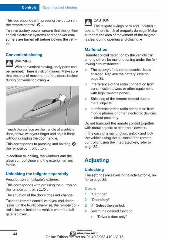
Convenient closingWARNINGWith convenient closing, body parts can
be jammed. There is risk of injuries. Make surethat the area of movement of the doors is clearduring convenient closing.◀
Touch the surface on the handle of a vehicledoor, arrow, with your finger and hold it therewithout grasping the door handle.This corresponds to pressing and holding the remote control button.
In addition to locking, the windows and theglass sunroof close and the exterior mirrorsfold in.
Unlocking the tailgate separatelyPress button on tailgate's exterior.This corresponds with pressing the button onthe remote control. .The situation of the doors does not change.Take the remote control with you and do notleave it in the trunk; otherwise, the remote con‐trol is locked inside the vehicle when the tail‐gate is closed.
CAUTIONThe tailgate swings back and up when it
opens. There is risk of property damage. Makesure that the area of movement of the tailgateis clear during opening and closing.◀
MalfunctionRemote control detection by the vehicle canamong others be malfunctioning under the fol‐lowing circumstances:▷ The battery of the remote control is dis‐
charged. Replace the battery, refer topage 35.
▷ Interference of the radio connection fromtransmission towers or other equipmentwith high transmit power.
▷ Shielding of the remote control due tometal objects.
▷ Interference of the radio connection frommobile phones or other electronic devicesin direct proximity.
Do not transport the remote control togetherwith metal objects or electronic devices.In the case of a malfunction, unlock and lockthe vehicle using the buttons of the remotecontrol or using the integrated key, refer topage 39.
AdjustingUnlockingThe settings are saved in the active profile, re‐fer to page 35.
Doors1. "Settings"2. "Doors/key"3. Select the symbol.4. Select the desired function:
▷ "Driver's door only"
Seite 44
Controls Opening and closing
44Online Edition for Part no. 01 40 2 963 410 - VI/15
Information Provided by:
Only the driver's door and the fuel fillerflap are unlocked. Pressing again un‐locks the entire vehicle.
▷ "All doors"The entire vehicle is unlocked.
TailgateDepending on optional features and countryversion, this setting is not offered in somecases.
1. "Settings"2. "Doors/key"3. Select the symbol.4. Select the desired function:
▷ "Tailgate"The tailgate is opened.
▷ "Tailgate + door(s)"The tailgate is opened and the doorsunlocked.
Confirmation signals from the vehicleThe settings are saved in the active profile, re‐fer to page 35.
1. "Settings"2. "Doors/key"3. Deactivate or activate the desired confir‐
mation signals.▷ "Acoustic sig. lock/unlock"▷ "Flash when lock/unlock"
Automatic lockingThe settings are saved in the active profile, re‐fer to page 35.
1. "Settings"2. "Doors/key"3. Select the desired function:
▷ "Lock if no door is opened"
The vehicle locks automatically after ashort period of time if no door isopened.
▷ "Lock after start driving"The vehicle locks automatically afteryou drive off.
Retrieving the seat, mirror, andsteering wheel settingsThe driver's seat, exterior mirror, and steeringwheel position adjusted last will be stored forthe active profile.When the vehicle is unlocked, these positionsare automatically retrieved if this function wasactivated.
WARNINGThere is risk of jamming when moving
the seats. There is risk of injuries or risk ofproperty damage. Make sure that the area ofmovement of the seat is clear prior to any ad‐justment.◀
The adjustment procedure is interrupted:▷ When a seat position switch is pressed.▷ When a button of the seat, mirror, and
steering wheel memory is pressed briefly.
Activating the setting1. "Settings"2. "Doors/key"3. "Last seat position autom."
Alarm systemThe conceptWhen the vehicle is locked, the vehicle alarmsystem responds to:▷ Opening a door, the hood or the tailgate.▷ Movements in the interior.
Seite 45
Opening and closing Controls
45Online Edition for Part no. 01 40 2 963 410 - VI/15
Information Provided by:
▷ Changes in the vehicle tilt, e. g., during at‐tempts at stealing a wheel or when towingthe car.
▷ Disconnected battery voltage.The alarm system briefly signals tampering:▷ By sounding an acoustic alarm.▷ By switching on the hazard warning sys‐
tem.▷ By flashing the daytime running lights.
Arming and disarming the alarmsystemWhen you unlock or lock the vehicle, eitherwith the remote control or via the Comfort Ac‐cess, the alarm system is disarmed or armed atthe same time.
Door lock and armed alarm systemThe alarm system is triggered when the door isopened, when the vehicle is unlocked via thedoor lock.
Tailgate and armed alarm systemThe tailgate can be opened even when thealarm system is armed.After the tailgate is closed, it is locked andmonitored again when the doors are locked.The hazard warning system flashes once.
Panic modeYou can trigger the alarm system if you findyourself in a dangerous situation.
Press button on the remote control forat least 3 seconds.
To switch off the alarm: press any button.
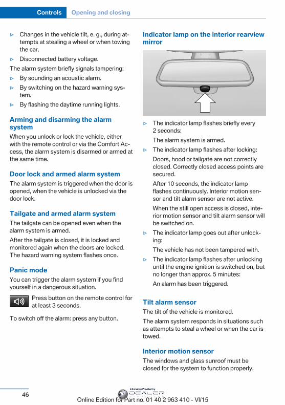
Indicator lamp on the interior rearviewmirror
▷ The indicator lamp flashes briefly every2 seconds:The alarm system is armed.
▷ The indicator lamp flashes after locking:Doors, hood or tailgate are not correctlyclosed. Correctly closed access points aresecured.After 10 seconds, the indicator lampflashes continuously. Interior motion sen‐sor and tilt alarm sensor are not active.When the still open access is closed, inte‐rior motion sensor and tilt alarm sensor willbe switched on.
▷ The indicator lamp goes out after unlock‐ing:The vehicle has not been tampered with.
▷ The indicator lamp flashes after unlockinguntil the engine ignition is switched on, butno longer than approx. 5 minutes:An alarm has been triggered.
Tilt alarm sensorThe tilt of the vehicle is monitored.The alarm system responds in situations suchas attempts to steal a wheel or when the car istowed.
Interior motion sensorThe windows and glass sunroof must beclosed for the system to function properly.
Seite 46
Controls Opening and closing
46Online Edition for Part no. 01 40 2 963 410 - VI/15
Information Provided by:
Avoiding unintentional alarmsThe tilt alarm sensor and interior motion sen‐sor can be switched off together, such as inthe following situations:▷ In automatic car washes.▷ In duplex garages.▷ During transport on trains carrying vehi‐
cles, at sea or on a trailer.▷ With animals in the vehicle.
Switching off the tilt alarm sensor andinterior motion sensor
Press the remote control button againwithin 10 seconds as soon as the vehicle
is locked.The indicator lamp lights up for approx. 2 sec‐onds and then continues to flash.The tilt alarm sensor and interior motion sen‐sor are turned off until the vehicle is lockedagain.
Switching off the alarm▷ Unlock vehicle with the remote control or
switch on the ignition, if needed throughemergency detection of remote control, re‐fer to page 35.
▷ With Comfort Access: if you are carryingthe remote control on your person, graspthe driver side or front passenger side doorhandle completely.
Power windowsInformation
WARNINGUnattended children or animals can
move the vehicle and endanger themselvesand traffic, e.g. with the following actions:▷ Pressing the Start/Stop button.▷ Releasing the parking brake.
▷ Opening and closing of doors or windows.▷ Shifting the selector lever into neutral.▷ Using vehicle equipment.There is risk of accidents or injuries. Do notleave children or animals unattended in the ve‐hicle. Carry remote control along when exitingand lock the vehicle.◀
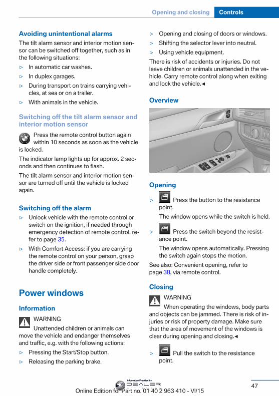
Overview
Opening
▷ Press the button to the resistancepoint.The window opens while the switch is held.
▷ Press the switch beyond the resist‐ance point.The window opens automatically. Pressingthe switch again stops the motion.
See also: Convenient opening, refer topage 38, via remote control.
ClosingWARNINGWhen operating the windows, body parts
and objects can be jammed. There is risk of in‐juries or risk of property damage. Make surethat the area of movement of the windows isclear during opening and closing.◀
▷ Pull the switch to the resistancepoint.
Seite 47
Opening and closing Controls
47Online Edition for Part no. 01 40 2 963 410 - VI/15
Information Provided by:
The window closes while the switch isheld.
▷ Pull the switch beyond the resistancepoint.The window closes automatically. Pullingagain stops the motion.
See also: closing by means of Comfort Access,refer to page 43.
Pinch protection systemWARNINGWhen operating the windows, body parts
and objects can be jammed. There is risk of in‐juries or risk of property damage. Make surethat the area of movement of the windows isclear during opening and closing.◀
WARNINGAccessories on the windows such as an‐
tennas can impact jam protection. There is riskof injuries. Do not install accessories in thearea of movement of the windows.◀
If closing force exceeds a specific margin as awindow closes, closing is interrupted.The window reopens slightly.
Closing without the pinch protectionsystem
WARNINGWhen operating the windows, body parts
and objects can be jammed. There is risk of in‐juries or risk of property damage. Make surethat the area of movement of the windows isclear during opening and closing.◀
In case of danger from the outside or if icemight prevent normal closing, proceed as fol‐lows:
1. Pull the switch past the resistance pointand hold it there.
The pinch protection is limited and thewindow reopens slightly if the closing forceexceeds a certain margin.
2. Pull the switch past the resistance pointagain within approx. 4 seconds and hold itthere.The window closes without jam protection.
Safety switch
General informationThe safety switch in the driver's door can beused to prevent children, e.g., from openingand closing the rear windows using theswitches in the rear.
InformationWARNINGWhen operating the windows, body parts
and objects can be jammed. There is risk of in‐juries or risk of property damage. Make surethat the area of movement of the windows isclear during opening and closing.◀
In order to prevent uncontrolled closing of thewindows, press the safety switch, e.g. if chil‐dren or animals are carried in the rear.
Switching on and offPress button.The LED lights up if the safety func‐
tion is switched on.
Roller sunblindsRoller sunblinds for the rear sidewindowsPull out the roller sunblind at the loop and hookit onto the bracket.
Seite 48
Controls Opening and closing
48Online Edition for Part no. 01 40 2 963 410 - VI/15
Information Provided by:
WARNINGWith closed roller sunblinds and open
windows, the roller sunblinds can be loadedheavily while driving due to the wind. The rollersunblinds can be damaged and compromisethe passengers. There is risk of injuries. Do notopen the windows while driving if the rollersunblinds are closed.◀
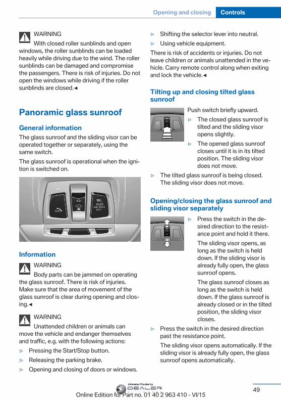
Panoramic glass sunroofGeneral informationThe glass sunroof and the sliding visor can beoperated together or separately, using thesame switch.The glass sunroof is operational when the igni‐tion is switched on.
InformationWARNINGBody parts can be jammed on operating
the glass sunroof. There is risk of injuries.Make sure that the area of movement of theglass sunroof is clear during opening and clos‐ing.◀
WARNINGUnattended children or animals can
move the vehicle and endanger themselvesand traffic, e.g. with the following actions:▷ Pressing the Start/Stop button.▷ Releasing the parking brake.▷ Opening and closing of doors or windows.
▷ Shifting the selector lever into neutral.▷ Using vehicle equipment.There is risk of accidents or injuries. Do notleave children or animals unattended in the ve‐hicle. Carry remote control along when exitingand lock the vehicle.◀
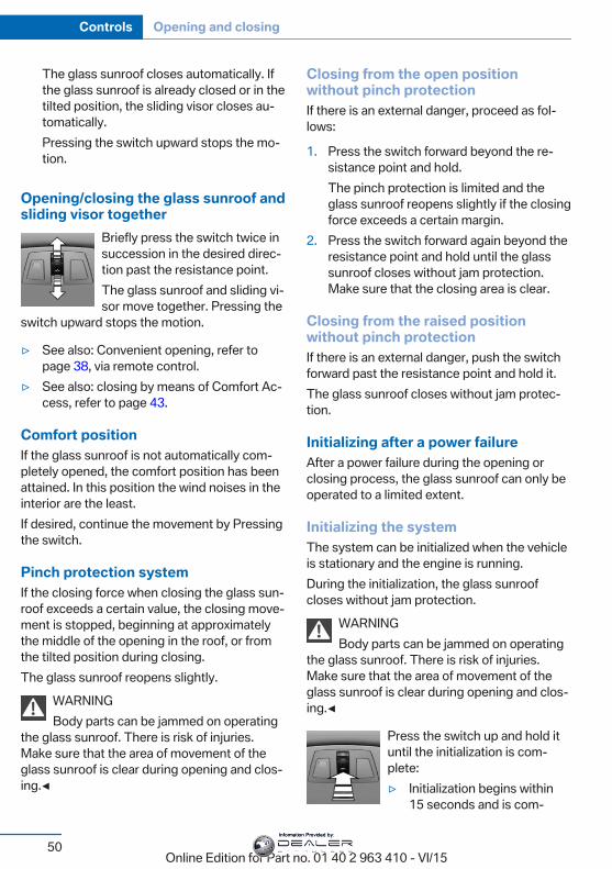
Tilting up and closing tilted glasssunroof
Push switch briefly upward.▷ The closed glass sunroof is
tilted and the sliding visoropens slightly.
▷ The opened glass sunroofcloses until it is in its tiltedposition. The sliding visordoes not move.
▷ The tilted glass sunroof is being closed.The sliding visor does not move.
Opening/closing the glass sunroof andsliding visor separately
▷ Press the switch in the de‐sired direction to the resist‐ance point and hold it there.The sliding visor opens, aslong as the switch is helddown. If the sliding visor isalready fully open, the glasssunroof opens.The glass sunroof closes aslong as the switch is helddown. If the glass sunroof isalready closed or in the tiltedposition, the sliding visorcloses.
▷ Press the switch in the desired directionpast the resistance point.The sliding visor opens automatically. If thesliding visor is already fully open, the glasssunroof opens automatically.
Seite 49
Opening and closing Controls
49Online Edition for Part no. 01 40 2 963 410 - VI/15
Information Provided by:
The glass sunroof closes automatically. Ifthe glass sunroof is already closed or in thetilted position, the sliding visor closes au‐tomatically.Pressing the switch upward stops the mo‐tion.
Opening/closing the glass sunroof andsliding visor together
Briefly press the switch twice insuccession in the desired direc‐tion past the resistance point.The glass sunroof and sliding vi‐sor move together. Pressing the
switch upward stops the motion.
▷ See also: Convenient opening, refer topage 38, via remote control.
▷ See also: closing by means of Comfort Ac‐cess, refer to page 43.
Comfort positionIf the glass sunroof is not automatically com‐pletely opened, the comfort position has beenattained. In this position the wind noises in theinterior are the least.If desired, continue the movement by Pressingthe switch.
Pinch protection systemIf the closing force when closing the glass sun‐roof exceeds a certain value, the closing move‐ment is stopped, beginning at approximatelythe middle of the opening in the roof, or fromthe tilted position during closing.The glass sunroof reopens slightly.
WARNINGBody parts can be jammed on operating
the glass sunroof. There is risk of injuries.Make sure that the area of movement of theglass sunroof is clear during opening and clos‐ing.◀
Closing from the open positionwithout pinch protectionIf there is an external danger, proceed as fol‐lows:
1. Press the switch forward beyond the re‐sistance point and hold.The pinch protection is limited and theglass sunroof reopens slightly if the closingforce exceeds a certain margin.
2. Press the switch forward again beyond theresistance point and hold until the glasssunroof closes without jam protection.Make sure that the closing area is clear.
Closing from the raised positionwithout pinch protectionIf there is an external danger, push the switchforward past the resistance point and hold it.The glass sunroof closes without jam protec‐tion.
Initializing after a power failureAfter a power failure during the opening orclosing process, the glass sunroof can only beoperated to a limited extent.
Initializing the systemThe system can be initialized when the vehicleis stationary and the engine is running.During the initialization, the glass sunroofcloses without jam protection.
WARNINGBody parts can be jammed on operating
the glass sunroof. There is risk of injuries.Make sure that the area of movement of theglass sunroof is clear during opening and clos‐ing.◀
Press the switch up and hold ituntil the initialization is com‐plete:▷ Initialization begins within
15 seconds and is com‐
Seite 50
Controls Opening and closing
50Online Edition for Part no. 01 40 2 963 410 - VI/15
Information Provided by:

pleted when the glass sun‐roof and sliding visor arecompletely closed.
▷ The glass sunroof closes without jam pro‐tection.
Seite 51
Opening and closing Controls
51Online Edition for Part no. 01 40 2 963 410 - VI/15
Information Provided by:
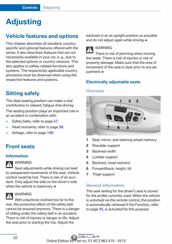
AdjustingVehicle features and optionsThis chapter describes all standard, country-specific and optional features offered with theseries. It also describes features that are notnecessarily available in your car, e. g., due tothe selected options or country versions. Thisalso applies to safety-related functions andsystems. The respectively applicable countryprovisions must be observed when using therespective features and systems.
Sitting safelyThe ideal seating position can make a vitalcontribution to relaxed, fatigue-free driving.The seating position plays an important role inan accident in combination with:▷ Safety belts, refer to page 57.▷ Head restraints, refer to page 58.▷ Airbags, refer to page 109.
Front seatsInformation
WARNINGSeat adjustments while driving can lead
to unexpected movements of the seat. Vehiclecontrol could be lost. There is risk of an acci‐dent. Only adjust the side on the driver's sidewhen the vehicle is stationary.◀
WARNINGWith a backrest inclined too far to the
rear, the protective effect of the safety beltcannot be ensured anymore. There is a dangerof sliding under the safety belt in an accident.There is risk of injuries or danger to life. Adjustthe seat prior to starting the trip. Adjust the
backrest in an as upright position as possibleand do not adjust again while driving.◀
WARNINGThere is risk of jamming when moving
the seats. There is risk of injuries or risk ofproperty damage. Make sure that the area ofmovement of the seat is clear prior to any ad‐justment.◀
Electrically adjustable seats
Overview
1 Seat, mirror, and steering wheel memory2 Shoulder support3 Backrest width4 Lumbar support5 Backrest, head restraint6 Forward/back, height, tilt7 Thigh support
General informationThe seat setting for the driver's seat is storedfor the profile currently used. When the vehicleis unlocked via the remote control, the positionis automatically retrieved if the Function, referto page 45, is activated for this purpose.
Seite 52
Controls Adjusting
52Online Edition for Part no. 01 40 2 963 410 - VI/15
Information Provided by:
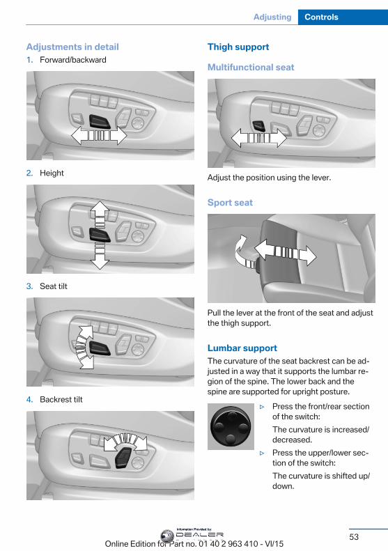
Adjustments in detail1. Forward/backward
2. Height
3. Seat tilt
4. Backrest tilt
Thigh support
Multifunctional seat
Adjust the position using the lever.
Sport seat
Pull the lever at the front of the seat and adjustthe thigh support.
Lumbar supportThe curvature of the seat backrest can be ad‐justed in a way that it supports the lumbar re‐gion of the spine. The lower back and thespine are supported for upright posture.
▷ Press the front/rear sectionof the switch:The curvature is increased/decreased.
▷ Press the upper/lower sec‐tion of the switch:The curvature is shifted up/down.
Seite 53
Adjusting Controls
53Online Edition for Part no. 01 40 2 963 410 - VI/15
Information Provided by:
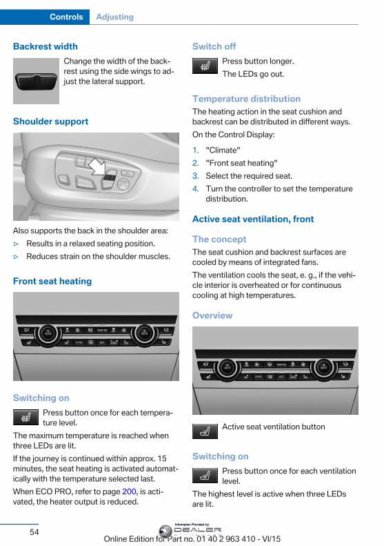
Backrest widthChange the width of the back‐rest using the side wings to ad‐just the lateral support.
Shoulder support
Also supports the back in the shoulder area:▷ Results in a relaxed seating position.▷ Reduces strain on the shoulder muscles.
Front seat heating
Switching onPress button once for each tempera‐ture level.
The maximum temperature is reached whenthree LEDs are lit.If the journey is continued within approx. 15minutes, the seat heating is activated automat‐ically with the temperature selected last.When ECO PRO, refer to page 200, is acti‐vated, the heater output is reduced.
Switch offPress button longer.The LEDs go out.
Temperature distributionThe heating action in the seat cushion andbackrest can be distributed in different ways.On the Control Display:
1. "Climate"2. "Front seat heating"3. Select the required seat.4. Turn the controller to set the temperature
distribution.
Active seat ventilation, front
The conceptThe seat cushion and backrest surfaces arecooled by means of integrated fans.The ventilation cools the seat, e. g., if the vehi‐cle interior is overheated or for continuouscooling at high temperatures.
Overview
Active seat ventilation button
Switching onPress button once for each ventilationlevel.
The highest level is active when three LEDsare lit.
Seite 54
Controls Adjusting
54Online Edition for Part no. 01 40 2 963 410 - VI/15
Information Provided by:
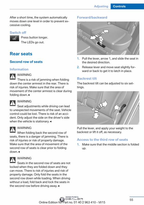
After a short time, the system automaticallymoves down one level in order to prevent ex‐cessive cooling.
Switch offPress button longer.The LEDs go out.
Rear seatsSecond row of seats
InformationWARNINGThere is a risk of jamming when folding
down the center armrest in the rear. There isrisk of injuries. Make sure that the area ofmovement of the center armrest is clear duringfolding down.◀
WARNINGSeat adjustments while driving can lead
to unexpected movements of the seat. Vehiclecontrol could be lost. There is risk of an acci‐dent. Only adjust the side on the driver's sidewhen the vehicle is stationary.◀
WARNINGWhen folding back the second row of
seats, there is a danger of jamming. There isrisk of injuries or risk of property damage.Make sure that the area of movement of thesecond row of seats is clear prior to foldingdown.◀
WARNINGSeats in the second row of seats are not
locked when they are folded down and theycan move. There is risk of injuries and risk ofproperty damage. Only fold the seats in thesecond row down while loading. When drivingwithout a load, fold back and lock the seats inthe second row before driving away.◀
Forward/backward
1. Pull the lever, arrow 1, and slide the seat inthe desired direction.
2. Release lever and move seat slightly for‐ward or back to get it to latch in place.
Backrest tiltThe backrest tilt can be adjusted to six set‐tings.
Pull the lever, and apply your weight to thebackrest or lift it off, as necessary.
Access to the third row of seats1. Make sure that the middle section is folded
up.
Seite 55
Adjusting Controls
55Online Edition for Part no. 01 40 2 963 410 - VI/15
Information Provided by:
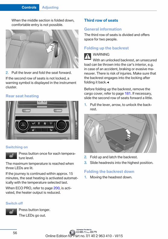
When the middle section is folded down,comfortable entry is not possible.
2. Pull the lever and fold the seat forward.If the second row of seats is not locked, awarning symbol is displayed in the instrumentcluster.
Rear seat heating
Switching onPress button once for each tempera‐ture level.
The maximum temperature is reached whenthree LEDs are lit.If the journey is continued within approx. 15minutes, the seat heating is activated automat‐ically with the temperature selected last.When ECO PRO, refer to page 200, is acti‐vated, the heater output is reduced.
Switch offPress button longer.The LEDs go out.
Third row of seats
General informationThe third row of seats is divided and offersspace for two people.
Folding up the backrestWARNINGWith an unlocked backrest, an unsecured
load can be thrown into the car's interior, e.g.in case of an accident, braking or evasive ma‐neuver. There is risk of injuries. Make sure thatthe backrest engages into the locking afterfolding it back.◀
Before folding up the backrest, remove thecargo cover, refer to page 181. If necessary,slide the second row of seats forward a little.
1. Pull the lever, arrow, to unlock the back‐rest.
2. Fold up and latch the backrest.3. Slide headrests into the highest position.
Folding the backrest down1. Moving the headrest down.
Seite 56
Controls Adjusting
56Online Edition for Part no. 01 40 2 963 410 - VI/15
Information Provided by:
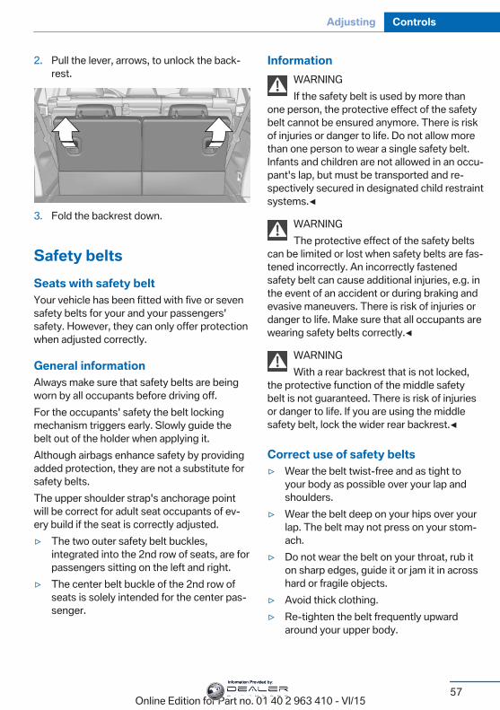
2. Pull the lever, arrows, to unlock the back‐rest.
3. Fold the backrest down.
Safety beltsSeats with safety beltYour vehicle has been fitted with five or sevensafety belts for your and your passengers'safety. However, they can only offer protectionwhen adjusted correctly.
General informationAlways make sure that safety belts are beingworn by all occupants before driving off.For the occupants' safety the belt lockingmechanism triggers early. Slowly guide thebelt out of the holder when applying it.Although airbags enhance safety by providingadded protection, they are not a substitute forsafety belts.The upper shoulder strap's anchorage pointwill be correct for adult seat occupants of ev‐ery build if the seat is correctly adjusted.▷ The two outer safety belt buckles,
integrated into the 2nd row of seats, are forpassengers sitting on the left and right.
▷ The center belt buckle of the 2nd row ofseats is solely intended for the center pas‐senger.
InformationWARNINGIf the safety belt is used by more than
one person, the protective effect of the safetybelt cannot be ensured anymore. There is riskof injuries or danger to life. Do not allow morethan one person to wear a single safety belt.Infants and children are not allowed in an occu‐pant's lap, but must be transported and re‐spectively secured in designated child restraintsystems.◀
WARNINGThe protective effect of the safety belts
can be limited or lost when safety belts are fas‐tened incorrectly. An incorrectly fastenedsafety belt can cause additional injuries, e.g. inthe event of an accident or during braking andevasive maneuvers. There is risk of injuries ordanger to life. Make sure that all occupants arewearing safety belts correctly.◀
WARNINGWith a rear backrest that is not locked,
the protective function of the middle safetybelt is not guaranteed. There is risk of injuriesor danger to life. If you are using the middlesafety belt, lock the wider rear backrest.◀
Correct use of safety belts▷ Wear the belt twist-free and as tight to
your body as possible over your lap andshoulders.
▷ Wear the belt deep on your hips over yourlap. The belt may not press on your stom‐ach.
▷ Do not wear the belt on your throat, rub iton sharp edges, guide it or jam it in acrosshard or fragile objects.
▷ Avoid thick clothing.▷ Re-tighten the belt frequently upward
around your upper body.
Seite 57
Adjusting Controls
57Online Edition for Part no. 01 40 2 963 410 - VI/15
Information Provided by:
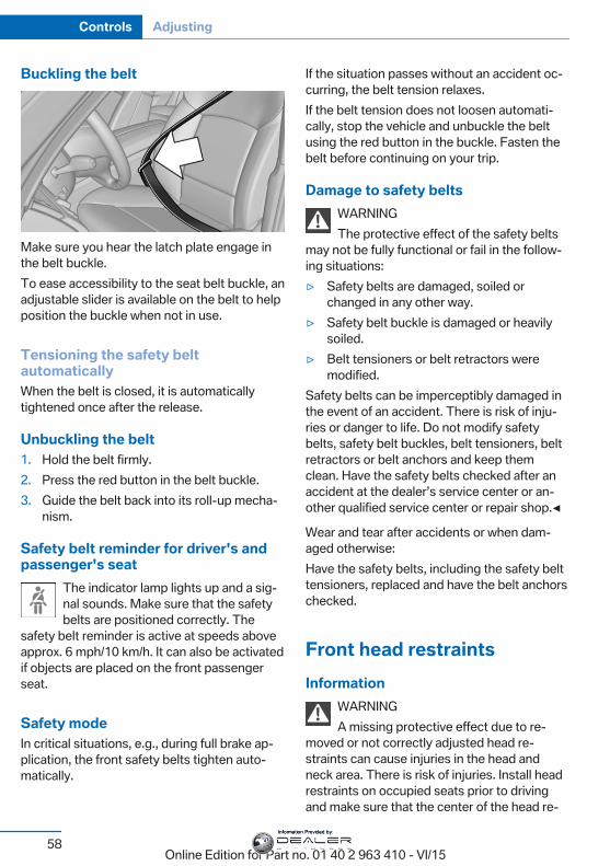
Buckling the belt
Make sure you hear the latch plate engage inthe belt buckle.To ease accessibility to the seat belt buckle, anadjustable slider is available on the belt to helpposition the buckle when not in use.
Tensioning the safety beltautomaticallyWhen the belt is closed, it is automaticallytightened once after the release.
Unbuckling the belt1. Hold the belt firmly.2. Press the red button in the belt buckle.3. Guide the belt back into its roll-up mecha‐
nism.
Safety belt reminder for driver's andpassenger's seat
The indicator lamp lights up and a sig‐nal sounds. Make sure that the safetybelts are positioned correctly. The
safety belt reminder is active at speeds aboveapprox. 6 mph/10 km/h. It can also be activatedif objects are placed on the front passengerseat.
Safety modeIn critical situations, e.g., during full brake ap‐plication, the front safety belts tighten auto‐matically.
If the situation passes without an accident oc‐curring, the belt tension relaxes.If the belt tension does not loosen automati‐cally, stop the vehicle and unbuckle the beltusing the red button in the buckle. Fasten thebelt before continuing on your trip.
Damage to safety beltsWARNINGThe protective effect of the safety belts
may not be fully functional or fail in the follow‐ing situations:▷ Safety belts are damaged, soiled or
changed in any other way.▷ Safety belt buckle is damaged or heavily
soiled.▷ Belt tensioners or belt retractors were
modified.Safety belts can be imperceptibly damaged inthe event of an accident. There is risk of inju‐ries or danger to life. Do not modify safetybelts, safety belt buckles, belt tensioners, beltretractors or belt anchors and keep themclean. Have the safety belts checked after anaccident at the dealer’s service center or an‐other qualified service center or repair shop.◀
Wear and tear after accidents or when dam‐aged otherwise:Have the safety belts, including the safety belttensioners, replaced and have the belt anchorschecked.
Front head restraintsInformation
WARNINGA missing protective effect due to re‐
moved or not correctly adjusted head re‐straints can cause injuries in the head andneck area. There is risk of injuries. Install headrestraints on occupied seats prior to drivingand make sure that the center of the head re‐
Seite 58
Controls Adjusting
58Online Edition for Part no. 01 40 2 963 410 - VI/15
Information Provided by:
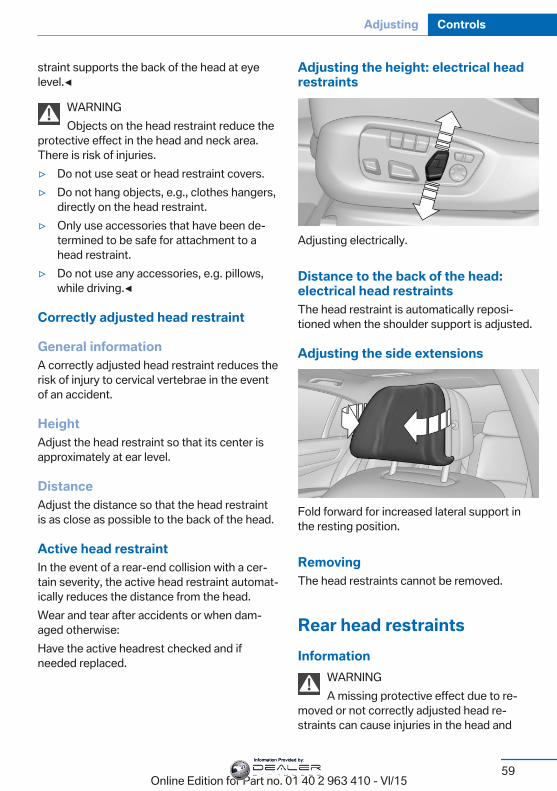
straint supports the back of the head at eyelevel.◀
WARNINGObjects on the head restraint reduce the
protective effect in the head and neck area.There is risk of injuries.▷ Do not use seat or head restraint covers.▷ Do not hang objects, e.g., clothes hangers,
directly on the head restraint.▷ Only use accessories that have been de‐
termined to be safe for attachment to ahead restraint.
▷ Do not use any accessories, e.g. pillows,while driving.◀
Correctly adjusted head restraint
General informationA correctly adjusted head restraint reduces therisk of injury to cervical vertebrae in the eventof an accident.
HeightAdjust the head restraint so that its center isapproximately at ear level.
DistanceAdjust the distance so that the head restraintis as close as possible to the back of the head.
Active head restraintIn the event of a rear-end collision with a cer‐tain severity, the active head restraint automat‐ically reduces the distance from the head.Wear and tear after accidents or when dam‐aged otherwise:Have the active headrest checked and ifneeded replaced.
Adjusting the height: electrical headrestraints
Adjusting electrically.
Distance to the back of the head:electrical head restraintsThe head restraint is automatically reposi‐tioned when the shoulder support is adjusted.
Adjusting the side extensions
Fold forward for increased lateral support inthe resting position.
RemovingThe head restraints cannot be removed.
Rear head restraintsInformation
WARNINGA missing protective effect due to re‐
moved or not correctly adjusted head re‐straints can cause injuries in the head and
Seite 59
Adjusting Controls
59Online Edition for Part no. 01 40 2 963 410 - VI/15
Information Provided by:
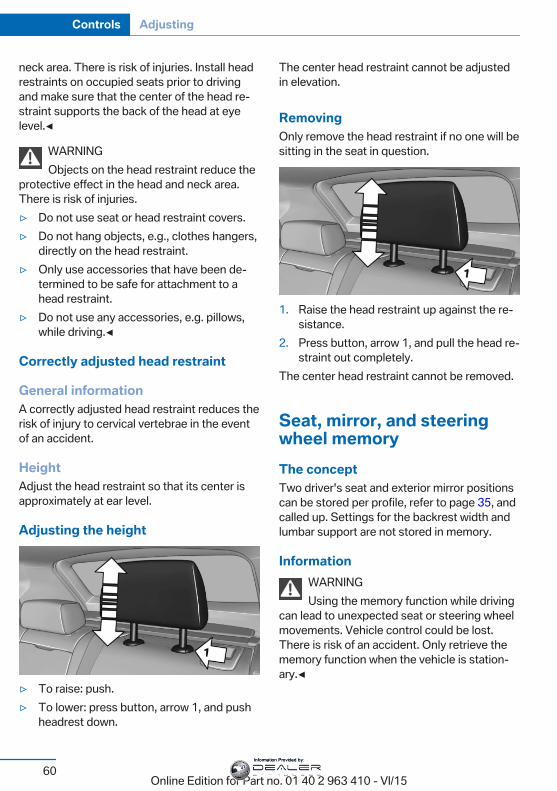
neck area. There is risk of injuries. Install headrestraints on occupied seats prior to drivingand make sure that the center of the head re‐straint supports the back of the head at eyelevel.◀
WARNINGObjects on the head restraint reduce the
protective effect in the head and neck area.There is risk of injuries.▷ Do not use seat or head restraint covers.▷ Do not hang objects, e.g., clothes hangers,
directly on the head restraint.▷ Only use accessories that have been de‐
termined to be safe for attachment to ahead restraint.
▷ Do not use any accessories, e.g. pillows,while driving.◀
Correctly adjusted head restraint
General informationA correctly adjusted head restraint reduces therisk of injury to cervical vertebrae in the eventof an accident.
HeightAdjust the head restraint so that its center isapproximately at ear level.
Adjusting the height
▷ To raise: push.▷ To lower: press button, arrow 1, and push
headrest down.
The center head restraint cannot be adjustedin elevation.
RemovingOnly remove the head restraint if no one will besitting in the seat in question.
1. Raise the head restraint up against the re‐sistance.
2. Press button, arrow 1, and pull the head re‐straint out completely.
The center head restraint cannot be removed.
Seat, mirror, and steeringwheel memoryThe conceptTwo driver's seat and exterior mirror positionscan be stored per profile, refer to page 35, andcalled up. Settings for the backrest width andlumbar support are not stored in memory.
InformationWARNINGUsing the memory function while driving
can lead to unexpected seat or steering wheelmovements. Vehicle control could be lost.There is risk of an accident. Only retrieve thememory function when the vehicle is station‐ary.◀
Seite 60
Controls Adjusting
60Online Edition for Part no. 01 40 2 963 410 - VI/15
Information Provided by:
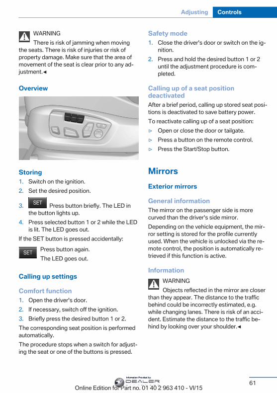
WARNINGThere is risk of jamming when moving
the seats. There is risk of injuries or risk ofproperty damage. Make sure that the area ofmovement of the seat is clear prior to any ad‐justment.◀
Overview
Storing1. Switch on the ignition.2. Set the desired position.
3. Press button briefly. The LED inthe button lights up.
4. Press selected button 1 or 2 while the LEDis lit. The LED goes out.
If the SET button is pressed accidentally:Press button again.The LED goes out.
Calling up settings
Comfort function1. Open the driver's door.2. If necessary, switch off the ignition.3. Briefly press the desired button 1 or 2.The corresponding seat position is performedautomatically.The procedure stops when a switch for adjust‐ing the seat or one of the buttons is pressed.
Safety mode1. Close the driver's door or switch on the ig‐
nition.2. Press and hold the desired button 1 or 2
until the adjustment procedure is com‐pleted.
Calling up of a seat positiondeactivatedAfter a brief period, calling up stored seat posi‐tions is deactivated to save battery power.To reactivate calling up of a seat position:▷ Open or close the door or tailgate.▷ Press a button on the remote control.▷ Press the Start/Stop button.
MirrorsExterior mirrors
General informationThe mirror on the passenger side is morecurved than the driver's side mirror.Depending on the vehicle equipment, the mir‐ror setting is stored for the profile currentlyused. When the vehicle is unlocked via the re‐mote control, the position is automatically re‐trieved if this function is active.
InformationWARNINGObjects reflected in the mirror are closer
than they appear. The distance to the trafficbehind could be incorrectly estimated, e.g.while changing lanes. There is risk of an acci‐dent. Estimate the distance to the traffic be‐hind by looking over your shoulder.◀
Seite 61
Adjusting Controls
61Online Edition for Part no. 01 40 2 963 410 - VI/15
Information Provided by:
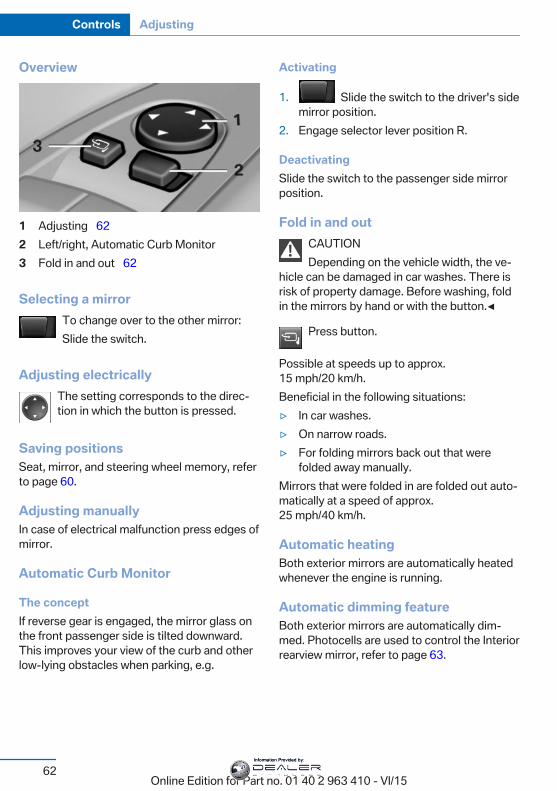
Overview
1 Adjusting 622 Left/right, Automatic Curb Monitor3 Fold in and out 62
Selecting a mirrorTo change over to the other mirror:Slide the switch.
Adjusting electricallyThe setting corresponds to the direc‐tion in which the button is pressed.
Saving positionsSeat, mirror, and steering wheel memory, referto page 60.
Adjusting manuallyIn case of electrical malfunction press edges ofmirror.
Automatic Curb Monitor
The conceptIf reverse gear is engaged, the mirror glass onthe front passenger side is tilted downward.This improves your view of the curb and otherlow-lying obstacles when parking, e.g.
Activating
1. Slide the switch to the driver's sidemirror position.
2. Engage selector lever position R.
DeactivatingSlide the switch to the passenger side mirrorposition.
Fold in and outCAUTIONDepending on the vehicle width, the ve‐
hicle can be damaged in car washes. There isrisk of property damage. Before washing, foldin the mirrors by hand or with the button.◀
Press button.
Possible at speeds up to approx.15 mph/20 km/h.Beneficial in the following situations:▷ In car washes.▷ On narrow roads.▷ For folding mirrors back out that were
folded away manually.Mirrors that were folded in are folded out auto‐matically at a speed of approx.25 mph/40 km/h.
Automatic heatingBoth exterior mirrors are automatically heatedwhenever the engine is running.
Automatic dimming featureBoth exterior mirrors are automatically dim‐med. Photocells are used to control the Interiorrearview mirror, refer to page 63.
Seite 62
Controls Adjusting
62Online Edition for Part no. 01 40 2 963 410 - VI/15
Information Provided by:
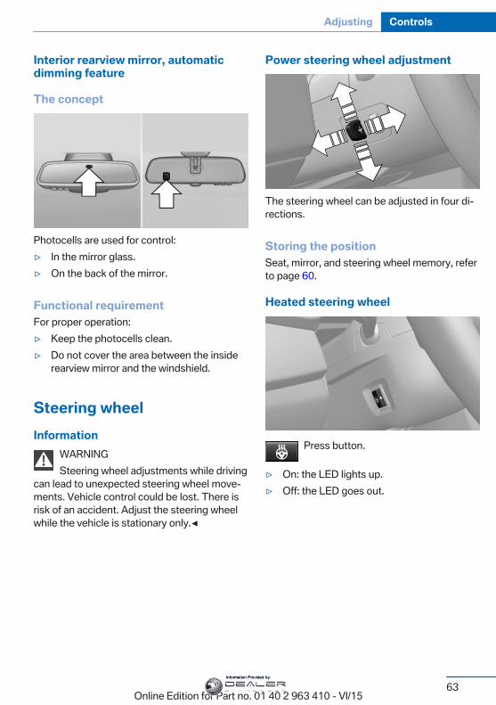
Interior rearview mirror, automaticdimming feature
The concept
Photocells are used for control:▷ In the mirror glass.▷ On the back of the mirror.
Functional requirementFor proper operation:▷ Keep the photocells clean.▷ Do not cover the area between the inside
rearview mirror and the windshield.
Steering wheelInformation
WARNINGSteering wheel adjustments while driving
can lead to unexpected steering wheel move‐ments. Vehicle control could be lost. There isrisk of an accident. Adjust the steering wheelwhile the vehicle is stationary only.◀
Power steering wheel adjustment
The steering wheel can be adjusted in four di‐rections.
Storing the positionSeat, mirror, and steering wheel memory, referto page 60.
Heated steering wheel
Press button.
▷ On: the LED lights up.▷ Off: the LED goes out.
Seite 63
Adjusting Controls
63Online Edition for Part no. 01 40 2 963 410 - VI/15
Information Provided by:
Transporting children safelyVehicle features and optionsThis chapter describes all standard, country-specific and optional features offered with theseries. It also describes features that are notnecessarily available in your car, e. g., due to
the selected options or country versions. Thisalso applies to safety-related functions andsystems. The respectively applicable countryprovisions must be observed when using therespective features and systems.
The right place for childrenInformation
WARNINGUnattended children or animals can
move the vehicle and endanger themselvesand traffic, e.g. with the following actions:▷ Pressing the Start/Stop button.▷ Releasing the parking brake.▷ Opening and closing of doors or windows.▷ Shifting the selector lever into neutral.▷ Using vehicle equipment.There is risk of accidents or injuries. Do notleave children or animals unattended in the ve‐hicle. Carry remote control along when exitingand lock the vehicle.◀
Children should always be in the rearWARNINGPersons shorter than 5 ft, 150 cm cannot
correctly fasten the safety belt without suitableadditional restraint systems. The protective ef‐fect of the safety belts can be limited or lostwhen safety belts are fastened incorrectly. Anincorrectly fastened safety belt can cause ad‐ditional injuries, e.g. in the event of an accidentor during braking and evasive maneuvers.There is risk of injuries or danger to life. Securepersons shorter than 5 ft, 150 cm using suita‐ble restraint systems.◀
Accident research shows that the safest placefor children is in the back seat.
Only transport children younger than 13 yearsof age or shorter than 5 ft, 150 cm in the rear inchild restraint systems provided in accordancewith the age, weight and size of the child.Children 13 years of age or older must wear asafety belt as soon as a suitable child restraintsystem can no longer be used due to their age,weight and size.
Children on the front passenger seatShould it ever be necessary to use a child re‐straint system in the front passenger seat,make sure that the front, knee and side airbagson the front passenger side are deactivated.Automatic deactivation of front-seat passen‐ger airbags, refer to page 111.
InformationWARNINGActive front-seat passenger airbags can
injure a child in a child restraint system whenthe airbags are activated. There is risk of inju‐ries. Make sure that the front-seat passengerairbags are deactivated and that the PASSEN‐GER AIRBAG OFF indicator lamp lights up.◀
WARNINGThe stability of the child restraint system
is limited or compromised with incorrect seatadjustment or improper installation of the childseat. There is risk of injuries or danger to life.Make sure that the child restraint system fits
Seite 64
Controls Transporting children safely
64Online Edition for Part no. 01 40 2 963 410 - VI/15
Information Provided by:
securely against the backrest. If possible, ad‐just the backrest tilt for all affected backrestsand correctly adjust the seats. Make sure thatseats and backrests are securely engaged. Ifpossible, adjust the height of the head re‐straints or remove them.◀
Installing child restraintsystemsBefore mountingBefore mounting child restraint systems, en‐sure that the rear seat backrests are locked.Move the rear seats into the rearmost positionto facilitate assembly of the child restraint sys‐tem.
InformationPay attention to the specifications of the childrestraint system manufacturer when selecting,installing, and using child restraint systems.
WARNINGThe stability of the child restraint system
is limited or compromised with incorrect seatadjustment or improper installation of the childseat. There is risk of injuries or danger to life.Make sure that the child restraint system fitssecurely against the backrest. If possible, ad‐just the backrest tilt for all affected backrestsand correctly adjust the seats. Make sure thatseats and backrests are securely engaged. Ifpossible, adjust the height of the head re‐straints or remove them.◀
WARNINGThere is limited protection provided if
child restraint systems are used on the thirdrow of seats. There is risk of injuries or dangerto life. Do not install child restraint systems onthe third row of seats.◀
On the front passenger seat
Deactivating airbagsWARNINGActive front-seat passenger airbags can
injure a child in a child restraint system whenthe airbags are activated. There is risk of inju‐ries. Make sure that the front-seat passengerairbags are deactivated and that the PASSEN‐GER AIRBAG OFF indicator lamp lights up.◀
After installing a child restraint system in thefront passenger seat, make sure that the front,knee and side airbags on the front passengerside are deactivated.Deactivate the front-seat passenger airbagsautomatically, refer to page 111.
Seat position and heightBefore installing a child restraint system, movethe front passenger seat as far back as possi‐ble and adjust its height to the highest andthus best possible position for the belt and tooffer optimal protection in the event of an acci‐dent.If the upper anchorage of the safety belt is lo‐cated in front of the belt guide of the child seat,move the passenger seat carefully forward un‐til the best possible belt guide position isreached.
Backrest widthAdjustable backrest width: before installing achild restraint system in the front passengerseat, open the backrest width completely. Donot change the backrest width again and donot call up a memory position.
Seite 65
Transporting children safely Controls
65Online Edition for Part no. 01 40 2 963 410 - VI/15
Information Provided by:
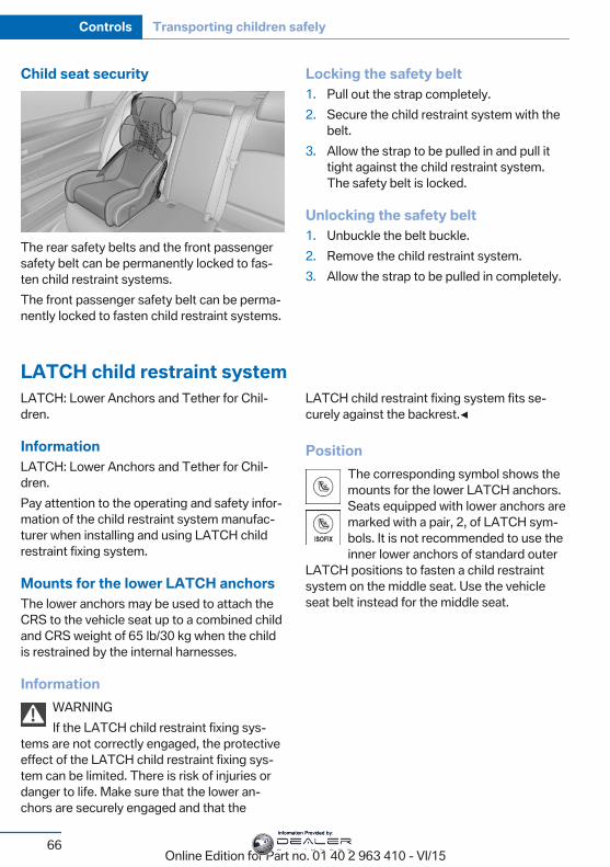
Child seat security
The rear safety belts and the front passengersafety belt can be permanently locked to fas‐ten child restraint systems.The front passenger safety belt can be perma‐nently locked to fasten child restraint systems.
Locking the safety belt1. Pull out the strap completely.2. Secure the child restraint system with the
belt.3. Allow the strap to be pulled in and pull it
tight against the child restraint system.The safety belt is locked.
Unlocking the safety belt1. Unbuckle the belt buckle.2. Remove the child restraint system.3. Allow the strap to be pulled in completely.
LATCH child restraint systemLATCH: Lower Anchors and Tether for Chil‐dren.
InformationLATCH: Lower Anchors and Tether for Chil‐dren.Pay attention to the operating and safety infor‐mation of the child restraint system manufac‐turer when installing and using LATCH childrestraint fixing system.
Mounts for the lower LATCH anchorsThe lower anchors may be used to attach theCRS to the vehicle seat up to a combined childand CRS weight of 65 lb/30 kg when the childis restrained by the internal harnesses.
InformationWARNINGIf the LATCH child restraint fixing sys‐
tems are not correctly engaged, the protectiveeffect of the LATCH child restraint fixing sys‐tem can be limited. There is risk of injuries ordanger to life. Make sure that the lower an‐chors are securely engaged and that the
LATCH child restraint fixing system fits se‐curely against the backrest.◀
PositionThe corresponding symbol shows themounts for the lower LATCH anchors.Seats equipped with lower anchors aremarked with a pair, 2, of LATCH sym‐bols. It is not recommended to use theinner lower anchors of standard outer
LATCH positions to fasten a child restraintsystem on the middle seat. Use the vehicleseat belt instead for the middle seat.
Seite 66
Controls Transporting children safely
66Online Edition for Part no. 01 40 2 963 410 - VI/15
Information Provided by:
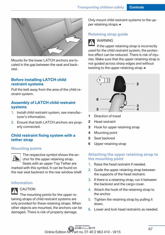
Mounts for the lower LATCH anchors are lo‐cated in the gap between the seat and back‐rest.
Before installing LATCH childrestraint systemsPull the belt away from the area of the child re‐straint system.
Assembly of LATCH child restraintsystems1. Install child restraint system, see manufac‐
turer's information.2. Ensure that both LATCH anchors are prop‐
erly connected.
Child restraint fixing system with atether strap
Mounting pointsThe respective symbol shows the an‐chor for the upper retaining strap.Seats with an upper Top Tether are
marked with this symbol. It can be found onthe rear seat backrest or the rear window shelf.
InformationCAUTIONThe mounting points for the upper re‐
taining straps of child restraint systems areonly provided for these retaining straps. Whenother objects are mounted, the anchors can bedamaged. There is risk of property damage.
Only mount child restraint systems to the up‐per retaining straps.◀
Retaining strap guideWARNINGIf the upper retaining strap is incorrectly
used for the child restraint system, the protec‐tive effect can be reduced. There is risk of inju‐ries. Make sure that the upper retaining strap isnot guided across sharp edges and withouttwisting to the upper retaining strap.◀
1 Direction of travel2 Head restraint3 Hook for upper retaining strap4 Mounting point5 Seat backrest6 Upper retaining strap
Attaching the upper retaining strap tothe mounting point1. Raise the head restraint if needed.2. Guide the upper retaining strap between
the supports of the head restraint.3. If there is a retaining strap, run it between
the backrest and the cargo cover.4. Attach the hook of the retaining strap to
the anchor.5. Tighten the retaining strap by pulling it
down.6. Lower and lock head restraints as needed.
Seite 67
Transporting children safely Controls
67Online Edition for Part no. 01 40 2 963 410 - VI/15
Information Provided by:
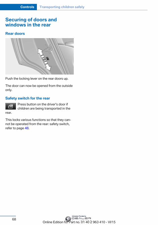
Securing of doors andwindows in the rearRear doors
Push the locking lever on the rear doors up.
The door can now be opened from the outsideonly.
Safety switch for the rearPress button on the driver's door ifchildren are being transported in the
rear.
This locks various functions so that they can‐not be operated from the rear: safety switch,refer to page 48.
Seite 68
Controls Transporting children safely
68Online Edition for Part no. 01 40 2 963 410 - VI/15
Information Provided by:
DrivingVehicle features and optionsThis chapter describes all standard, country-specific and optional features offered with theseries. It also describes features that are notnecessarily available in your car, e. g., due tothe selected options or country versions. Thisalso applies to safety-related functions andsystems. The respectively applicable countryprovisions must be observed when using therespective features and systems.
Start/Stop buttonThe concept
Pressing the Start/Stop buttonswitches the ignition on or offand starts the engine.The engine starts with the brakepedal pressed when you press
the Start/Stop button.
Ignition onPress the Start/Stop button, and do not presson the brake pedal at the same time.All vehicle systems are ready for operation.Most of the indicator and warning lights in theinstrument cluster light up for a varied lengthof time.To save battery power when the engine is off,switch off the ignition and any unnecessaryelectronic systems/power consumers.
Ignition offPress the Start/Stop button again withoutstepping on the brake.All indicator lights in the instrument cluster goout.
To save battery power when the engine is off,switch off the ignition and any unnecessaryelectronic systems/power consumers.
InformationWhen switching off the ignition, the selectorlever position P is selected automatically if theselector lever position D or R is selected.The ignition is switched off automatically in thefollowing situations while the vehicle is station‐ary and the engine is off:▷ When locking the vehicle, and when the
low beams are activated.▷ Shortly before the battery is discharged
completely, so that the engine can still bestarted.
▷ When opening or closing the driver door, ifthe driver's safety belt is unbuckled andthe low beams are turned off.
▷ While the driver's safety belt is unbuckledwith driver's door open and low beams off.
The low beams switch to parking lights afterapprox. 15 minutes of no use.
Radio ready stateActivate radio-ready state: when the engine isrunning: press the Start/Stop button.Some electronic systems/power consumersremain ready for operation.The radio-ready state is switched off automati‐cally in the following situations:▷ After approx. 8 minutes.▷ When the vehicle is locked using the cen‐
tral locking system.▷ Shortly before the battery is discharged
completely, so that the engine can still bestarted.
Seite 69
Driving Controls
69Online Edition for Part no. 01 40 2 963 410 - VI/15
Information Provided by:
The radio-ready state remains active if, e.g.,the ignition is automatically switched off for thefollowing reasons:▷ Opening or closing the driver's door.▷ Unfastening of the driver's safety belt.▷ When automatically switching from low
beams to parking lights.If the engine is switched off and the ignition isswitched on, the system automaticallyswitches to the radio-ready state if the lightsare turned off or, if correspondingly equipped,the daytime running lights are activated.
Starting the engineInformation
DANGERIf the exhaust pipe is blocked or ventila‐
tion is insufficient, harmful exhaust gases canenter into the vehicle. The exhaust gases con‐tain carbon monoxide, an odorless and color‐less but highly toxic gas. In enclosed areas, ex‐haust gases can also accumulate outside ofthe vehicle. There is danger to life. Keep theexhaust pipe free and ensure sufficient ventila‐tion.◀
WARNINGAn unsecured vehicle can put itself into
motion and roll away. There is risk of an acci‐dent. Before exiting, secure the vehicle againstrolling.In order to ensure that the vehicle is securedagainst rolling away, observe the following:▷ Set the parking brake.▷ On uphill grades or on a slope, turn the
front wheels in the direction of the curb.▷ On uphill grades or on a slope, also secure
the vehicle, e.g. with a wheel chock.◀
CAUTIONIn the case of repeated starting attempts
or repeated starting in quick succession, thefuel is not burned or is inadequately burned.The catalytic converter can overheat. There isrisk of property damage. Avoid repeated start‐ing in quick succession.◀
Diesel engineIf the engine is cold and temperatures are be‐low approx. 32 ℉/0 ℃, the start process maybe delayed somewhat due to automatic pre‐heating.A Check Control message is displayed.
Steptronic transmission
Starting the engine1. Depress the brake pedal.2. Press the Start/Stop button.The ignition is activated automatically for acertain time and is stopped as soon as the en‐gine starts.
Engine stopInformation
WARNINGUnattended children or animals can
move the vehicle and endanger themselvesand traffic, e.g. with the following actions:▷ Pressing the Start/Stop button.▷ Releasing the parking brake.▷ Opening and closing of doors or windows.▷ Shifting the selector lever into neutral.▷ Using vehicle equipment.There is risk of accidents or injuries. Do notleave children or animals unattended in the ve‐hicle. Carry remote control along when exitingand lock the vehicle.◀
Seite 70
Controls Driving
70Online Edition for Part no. 01 40 2 963 410 - VI/15
Information Provided by:

WARNINGAn unsecured vehicle can put itself into
motion and roll away. There is risk of an acci‐dent. Before exiting, secure the vehicle againstrolling.In order to ensure that the vehicle is securedagainst rolling away, observe the following:▷ Set the parking brake.▷ On uphill grades or on a slope, turn the
front wheels in the direction of the curb.▷ On uphill grades or on a slope, also secure
the vehicle, e.g. with a wheel chock.◀
Before driving into a car washSo that the vehicle can roll into a car wash ob‐serve instructions for going into an automaticcar wash, refer to page 254.
Steptronic transmission
Switching off the engine1. Engage selector lever position P with the
vehicle stopped.2. Press the Start/Stop button.
The engine is switched off.The radio-ready state is switched on.
3. Set the parking brake.
Auto Start/Stop functionThe conceptThe Auto Start/Stop function helps save fuel.The system switches off the engine during astop, e.g., in traffic congestion or at trafficlights. The ignition remains switched on. Theengine starts again automatically for drivingoff.
Automatic modeAfter every start of the engine using the Start/Stop button, the Auto Start/Stop function is inthe last selected state, refer to page 72.
When the Auto Start/Stop function is active, itis available when the vehicle is traveling fasterthan about 3 mph, approx. 5 km/h.
Engine stopThe engine is switched off automatically dur‐ing a stop under the following conditions:Steptronic transmission:▷ The selector lever is in selector lever posi‐
tion D.▷ The brake pedal remains pressed while the
vehicle is stationary or the vehicle is heldby Automatic Hold.
▷ The driver's safety belt is buckled or thedriver's door is closed.
The air flow from the air conditioner is reducedwhen the engine is switched off.
Displays in the instrument clusterThe display indicates that theAuto Start/Stop function isready for an Automatic enginestart.
The display indicates that theconditions for an automatic en‐gine stop have not been met.
Functional limitationsThe engine is not switched off automatically inthe following situations:▷ External temperature too low.▷ The external temperature is high and auto‐
matic climate control is running.▷ The car's interior has not yet been heated
or cooled to the required level.▷ The engine is not yet at operating temper‐
ature.▷ The wheels are at a sharp angle or the
steering wheel is being turned.
Seite 71
Driving Controls
71Online Edition for Part no. 01 40 2 963 410 - VI/15
Information Provided by:
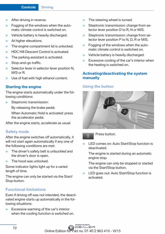
▷ After driving in reverse.▷ Fogging of the windows when the auto‐
matic climate control is switched on.▷ Vehicle battery is heavily discharged.▷ At higher elevations.▷ The engine compartment lid is unlocked.▷ HDC Hill Descent Control is activated.▷ The parking assistant is activated.▷ Stop-and-go traffic.▷ Selector lever in selector lever position N,
M/S or R.▷ Use of fuel with high ethanol content.
Starting the engineThe engine starts automatically under the fol‐lowing conditions:▷ Steptronic transmission:
By releasing the brake pedal.When Automatic Hold is activated: pressthe accelerator pedal.
After the engine starts, accelerate as usual.
Safety modeAfter the engine switches off automatically, itwill not start again automatically if any one ofthe following conditions are met:▷ The driver's safety belt is unbuckled and
the driver's door is open.▷ The hood was unlocked.Some indicator lights light up for a variedlength of time.The engine can only be started via the Start/Stop button.
Functional limitationsEven if driving off was not intended, the deacti‐vated engine starts up automatically in the fol‐lowing situations:▷ Excessive warming of the car's interior
when the cooling function is switched on.
▷ The steering wheel is turned.▷ Steptronic transmission: change from se‐
lector lever position D to R, N or M/S.▷ Steptronic transmission: change from se‐
lector lever position P to N, D, R or M/S.▷ Fogging of the windows when the auto‐
matic climate control is switched on.▷ Vehicle battery is heavily discharged.▷ Excessive cooling of the car's interior when
the heating is switched on.
Activating/deactivating the systemmanually
Using the button
Press button.
▷ LED comes on: Auto Start/Stop function isdeactivated.The engine is started during an automaticengine stop.The engine can only be stopped or startedvia the Start/Stop button.
▷ LED goes out: Auto Start/Stop function isactivated.
Seite 72
Controls Driving
72Online Edition for Part no. 01 40 2 963 410 - VI/15
Information Provided by:
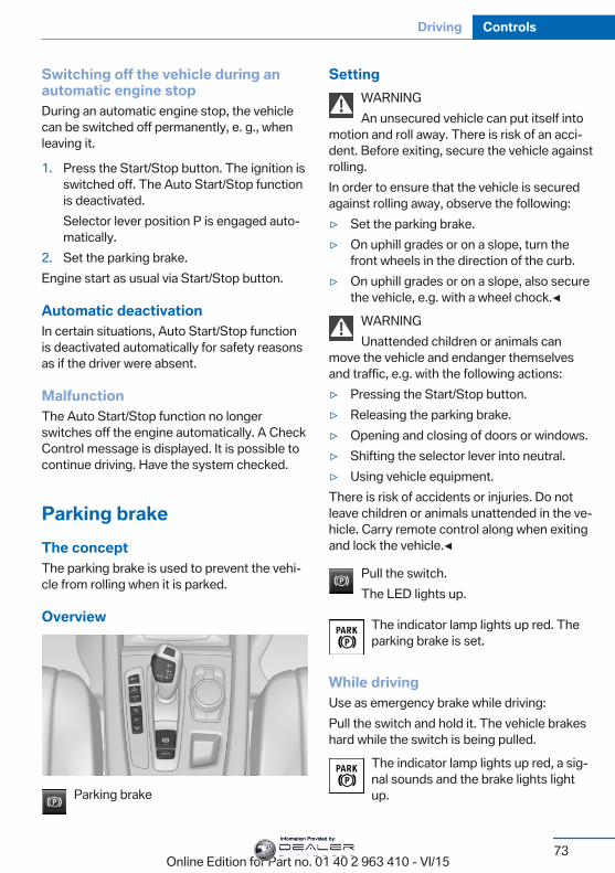
Switching off the vehicle during anautomatic engine stopDuring an automatic engine stop, the vehiclecan be switched off permanently, e. g., whenleaving it.
1. Press the Start/Stop button. The ignition isswitched off. The Auto Start/Stop functionis deactivated.Selector lever position P is engaged auto‐matically.
2. Set the parking brake.Engine start as usual via Start/Stop button.
Automatic deactivationIn certain situations, Auto Start/Stop functionis deactivated automatically for safety reasonsas if the driver were absent.
MalfunctionThe Auto Start/Stop function no longerswitches off the engine automatically. A CheckControl message is displayed. It is possible tocontinue driving. Have the system checked.
Parking brakeThe conceptThe parking brake is used to prevent the vehi‐cle from rolling when it is parked.
Overview
Parking brake
SettingWARNINGAn unsecured vehicle can put itself into
motion and roll away. There is risk of an acci‐dent. Before exiting, secure the vehicle againstrolling.In order to ensure that the vehicle is securedagainst rolling away, observe the following:▷ Set the parking brake.▷ On uphill grades or on a slope, turn the
front wheels in the direction of the curb.▷ On uphill grades or on a slope, also secure
the vehicle, e.g. with a wheel chock.◀WARNINGUnattended children or animals can
move the vehicle and endanger themselvesand traffic, e.g. with the following actions:▷ Pressing the Start/Stop button.▷ Releasing the parking brake.▷ Opening and closing of doors or windows.▷ Shifting the selector lever into neutral.▷ Using vehicle equipment.There is risk of accidents or injuries. Do notleave children or animals unattended in the ve‐hicle. Carry remote control along when exitingand lock the vehicle.◀
Pull the switch.The LED lights up.
The indicator lamp lights up red. Theparking brake is set.
While drivingUse as emergency brake while driving:Pull the switch and hold it. The vehicle brakeshard while the switch is being pulled.
The indicator lamp lights up red, a sig‐nal sounds and the brake lights lightup.
Seite 73
Driving Controls
73Online Edition for Part no. 01 40 2 963 410 - VI/15
Information Provided by:
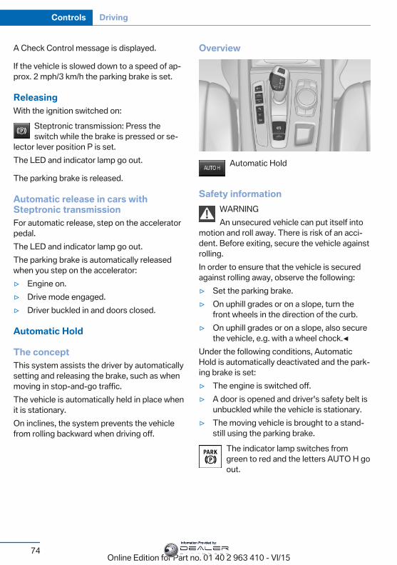
A Check Control message is displayed.
If the vehicle is slowed down to a speed of ap‐prox. 2 mph/3 km/h the parking brake is set.
ReleasingWith the ignition switched on:
Steptronic transmission: Press theswitch while the brake is pressed or se‐
lector lever position P is set.The LED and indicator lamp go out.
The parking brake is released.
Automatic release in cars withSteptronic transmissionFor automatic release, step on the acceleratorpedal.The LED and indicator lamp go out.The parking brake is automatically releasedwhen you step on the accelerator:▷ Engine on.▷ Drive mode engaged.▷ Driver buckled in and doors closed.
Automatic Hold
The conceptThis system assists the driver by automaticallysetting and releasing the brake, such as whenmoving in stop-and-go traffic.The vehicle is automatically held in place whenit is stationary.On inclines, the system prevents the vehiclefrom rolling backward when driving off.
Overview
Automatic Hold
Safety informationWARNINGAn unsecured vehicle can put itself into
motion and roll away. There is risk of an acci‐dent. Before exiting, secure the vehicle againstrolling.In order to ensure that the vehicle is securedagainst rolling away, observe the following:▷ Set the parking brake.▷ On uphill grades or on a slope, turn the
front wheels in the direction of the curb.▷ On uphill grades or on a slope, also secure
the vehicle, e.g. with a wheel chock.◀Under the following conditions, AutomaticHold is automatically deactivated and the park‐ing brake is set:▷ The engine is switched off.▷ A door is opened and driver's safety belt is
unbuckled while the vehicle is stationary.▷ The moving vehicle is brought to a stand‐
still using the parking brake.The indicator lamp switches fromgreen to red and the letters AUTO H goout.
Seite 74
Controls Driving
74Online Edition for Part no. 01 40 2 963 410 - VI/15
Information Provided by:
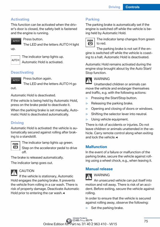
ActivatingThis function can be activated when the driv‐er's door is closed, the safety belt is fastenedand the engine is running.
Press button.The LED and the letters AUTO H light
up.
The indicator lamp lights up.Automatic Hold is activated.
DeactivatingPress button again.The LED and the letters AUTO H go
out.
Automatic Hold is deactivated.If the vehicle is being held by Automatic Hold,press on the brake pedal to deactivate it.When the parking brake is set manually, Auto‐matic Hold is deactivated automatically.
DrivingAutomatic Hold is activated: the vehicle is au‐tomatically secured against rolling after brak‐ing to a standstill.
The indicator lamp lights up green.Step on the accelerator pedal to driveoff.
The brake is released automatically.The indicator lamp goes out.
CAUTIONIf the vehicle is stationary, Automatic
Hold engages the parking brake. It preventsthe vehicle from rolling in a car wash. There isrisk of property damage. Deactivate AutomaticHold prior to entering the car wash.◀
ParkingThe parking brake is automatically set if theengine is switched off while the vehicle is be‐ing held by Automatic Hold.
The indicator lamp changes from greento red.The parking brake is not set if the en‐
gine is switched off while the vehicle is coast‐ing to a halt. Automatic Hold is deactivated.
Automatic Hold remains activated during theengine stop brought about by the Auto Start/Stop function.
WARNINGUnattended children or animals can
move the vehicle and endanger themselvesand traffic, e.g. with the following actions:▷ Pressing the Start/Stop button.▷ Releasing the parking brake.▷ Opening and closing of doors or windows.▷ Shifting the selector lever into neutral.▷ Using vehicle equipment.There is risk of accidents or injuries. Do notleave children or animals unattended in the ve‐hicle. Carry remote control along when exitingand lock the vehicle.◀
MalfunctionIn the event of a failure or malfunction of theparking brake, secure the vehicle against roll‐ing using a wheel chock, e.g., when leaving it.
Manual releaseWARNINGAn unsecured vehicle can put itself into
motion and roll away. There is risk of an acci‐dent. Before exiting, secure the vehicle againstrolling.In order to ensure that the vehicle is securedagainst rolling away, observe the following:▷ Set the parking brake.
Seite 75
Driving Controls
75Online Edition for Part no. 01 40 2 963 410 - VI/15
Information Provided by:
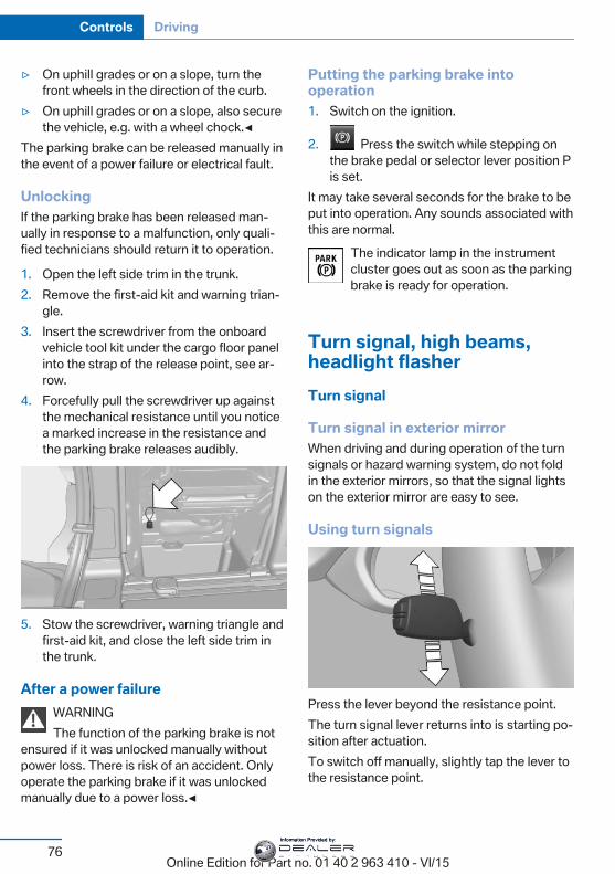
▷ On uphill grades or on a slope, turn thefront wheels in the direction of the curb.
▷ On uphill grades or on a slope, also securethe vehicle, e.g. with a wheel chock.◀
The parking brake can be released manually inthe event of a power failure or electrical fault.
UnlockingIf the parking brake has been released man‐ually in response to a malfunction, only quali‐fied technicians should return it to operation.
1. Open the left side trim in the trunk.2. Remove the first-aid kit and warning trian‐
gle.3. Insert the screwdriver from the onboard
vehicle tool kit under the cargo floor panelinto the strap of the release point, see ar‐row.
4. Forcefully pull the screwdriver up againstthe mechanical resistance until you noticea marked increase in the resistance andthe parking brake releases audibly.
5. Stow the screwdriver, warning triangle andfirst-aid kit, and close the left side trim inthe trunk.
After a power failureWARNINGThe function of the parking brake is not
ensured if it was unlocked manually withoutpower loss. There is risk of an accident. Onlyoperate the parking brake if it was unlockedmanually due to a power loss.◀
Putting the parking brake intooperation1. Switch on the ignition.
2. Press the switch while stepping onthe brake pedal or selector lever position Pis set.
It may take several seconds for the brake to beput into operation. Any sounds associated withthis are normal.
The indicator lamp in the instrumentcluster goes out as soon as the parkingbrake is ready for operation.
Turn signal, high beams,headlight flasherTurn signal
Turn signal in exterior mirrorWhen driving and during operation of the turnsignals or hazard warning system, do not foldin the exterior mirrors, so that the signal lightson the exterior mirror are easy to see.
Using turn signals
Press the lever beyond the resistance point.The turn signal lever returns into is starting po‐sition after actuation.To switch off manually, slightly tap the lever tothe resistance point.
Seite 76
Controls Driving
76Online Edition for Part no. 01 40 2 963 410 - VI/15
Information Provided by:
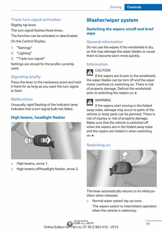
Triple turn signal activationSlightly tap lever.The turn signal flashes three times.The function can be activated or deactivated.On the Control Display:
1. "Settings"2. "Lighting"3. "Triple turn signal"Settings are stored for the profile currentlyused.
Signaling brieflyPress the lever to the resistance point and holdit there for as long as you want the turn signalto flash.
MalfunctionUnusually rapid flashing of the indicator lampindicates that a turn signal bulb has failed.
High beams, headlight flasher
▷ High beams, arrow 1.▷ High beams off/headlight flasher, arrow 2.
Washer/wiper systemSwitching the wipers on/off and briefwipe
General informationDo not use the wipers if the windshield is dry,as this may damage the wiper blades or causethem to become worn more quickly.
InformationCAUTIONIf the wipers are frozen to the windshield,
the wiper blades can be torn off and the wipermotor overheat on switching on. There is riskof property damage. Defrost the windshieldprior to switching the wipers on.◀
WARNINGIf the wipers start moving in the folded
away state, damage may occur to parts of thevehicle or body parts can be jammed. There isrisk of injuries or risk of property damage.Make sure that the vehicle is switched offwhen the wipers are in the folded away stateand the wipers are folded in when switchingon.◀
Switching on
The lever automatically returns to its initial po‐sition when released.▷ Normal wiper speed: tap up once.
The wipers switch to intermittent operationwhen the vehicle is stationary.
Seite 77
Driving Controls
77Online Edition for Part no. 01 40 2 963 410 - VI/15
Information Provided by:
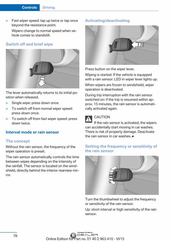
▷ Fast wiper speed: tap up twice or tap oncebeyond the resistance point.Wipers change to normal speed when ve‐hicle comes to standstill.
Switch off and brief wipe
The lever automatically returns to its initial po‐sition when released.▷ Single wipe: press down once.▷ To switch off from normal wiper speed:
press down once.▷ To switch off from fast wiper speed: press
down twice.
Interval mode or rain sensor
The conceptWithout the rain sensor, the frequency of thewiper operation is preset.The rain sensor automatically controls the timebetween wipes depending on the intensity ofthe rainfall. The sensor is located on the wind‐shield, directly behind the interior rearview mir‐ror.
Activating/deactivating
Press button on the wiper lever.Wiping is started. If the vehicle is equippedwith a rain sensor: LED in wiper lever lights up.When wipers are frozen to windshield, wiperoperation is deactivated.During trip interruption with the rain sensorswitched on: if the trip is resumed within ap‐prox. 15 minutes, the rain sensor is automati‐cally activated again.
CAUTIONIf the rain sensor is activated, the wipers
can accidentally start moving in car washes.There is risk of property damage. Deactivatethe rain sensor in car washes.◀
Setting the frequency or sensitivity ofthe rain sensor
Turn the thumbwheel to adjust the frequencyor sensitivity of the rain sensor.Up: short interval or high sensitivity of the rainsensor.
Seite 78
Controls Driving
78Online Edition for Part no. 01 40 2 963 410 - VI/15
Information Provided by:
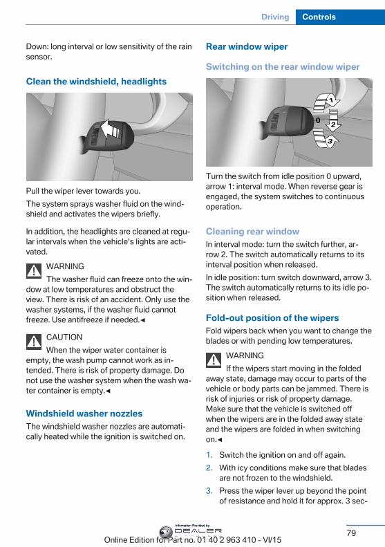
Down: long interval or low sensitivity of the rainsensor.
Clean the windshield, headlights
Pull the wiper lever towards you.The system sprays washer fluid on the wind‐shield and activates the wipers briefly.
In addition, the headlights are cleaned at regu‐lar intervals when the vehicle's lights are acti‐vated.
WARNINGThe washer fluid can freeze onto the win‐
dow at low temperatures and obstruct theview. There is risk of an accident. Only use thewasher systems, if the washer fluid cannotfreeze. Use antifreeze if needed.◀
CAUTIONWhen the wiper water container is
empty, the wash pump cannot work as in‐tended. There is risk of property damage. Donot use the washer system when the wash wa‐ter container is empty.◀
Windshield washer nozzlesThe windshield washer nozzles are automati‐cally heated while the ignition is switched on.
Rear window wiper
Switching on the rear window wiper
Turn the switch from idle position 0 upward,arrow 1: interval mode. When reverse gear isengaged, the system switches to continuousoperation.
Cleaning rear windowIn interval mode: turn the switch further, ar‐row 2. The switch automatically returns to itsinterval position when released.In idle position: turn switch downward, arrow 3.The switch automatically returns to its idle po‐sition when released.
Fold-out position of the wipersFold wipers back when you want to change theblades or with pending low temperatures.
WARNINGIf the wipers start moving in the folded
away state, damage may occur to parts of thevehicle or body parts can be jammed. There isrisk of injuries or risk of property damage.Make sure that the vehicle is switched offwhen the wipers are in the folded away stateand the wipers are folded in when switchingon.◀
1. Switch the ignition on and off again.2. With icy conditions make sure that blades
are not frozen to the windshield.3. Press the wiper lever up beyond the point
of resistance and hold it for approx. 3 sec‐
Seite 79
Driving Controls
79Online Edition for Part no. 01 40 2 963 410 - VI/15
Information Provided by:
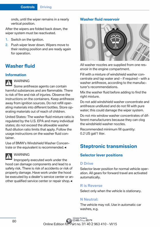
onds, until the wiper remains in a nearlyvertical position.
After the wipers are folded back down, thewiper system must be reactivated.
1. Switch on the ignition.2. Push wiper lever down. Wipers move to
their resting position and are ready againfor operation.
Washer fluidInformation
WARNINGSome antifreeze agents can contain
harmful substances and are flammable. Thereis risk of fire and risk of injuries. Observe theinstructions on the containers. Keep antifreezeaway from ignition sources. Do not refill oper‐ating materials into different bottles. Store op‐erating materials out of reach of children.United States: The washer fluid mixture ratio isregulated by the U.S. EPA and many individualstates; do not exceed the allowable washerfluid dilution ratio limits that apply. Follow theusage instructions on the washer fluid con‐tainer.Use of BMW’s Windshield Washer Concen‐trate or the equivalent is recommended.◀
WARNINGImproperly executed work under the
hood can damage components and lead to asafety risk. There is risk of accidents or risk ofproperty damage. Have work under the hoodbe executed by a dealer’s service center or an‐other qualified service center or repair shop.◀
Washer fluid reservoir
All washer nozzles are supplied from one res‐ervoir in the engine compartment.Fill with a mixture of windshield washer con‐centrate and tap water and – if required – with awasher antifreeze, according to the manufac‐turer's recommendations.Mix the washer fluid before adding to find theright mixture.Do not add windshield washer concentrate andantifreeze undiluted and do not fill with purewater; this could damage the wiper system.Do not mix window washer concentrates of dif‐ferent manufacturers because they can clogthe windshield washer nozzles.Recommended minimum fill quantity:0.2 US gal/1 liter.
Steptronic transmissionSelector lever positions
D DriveSelector lever position for normal vehicle oper‐ation. All gears for forward travel are activatedautomatically.
R is ReverseSelect only when the vehicle is stationary.
N Neutral:The vehicle may roll. Use in automatic carwashes, e.g.
Seite 80
Controls Driving
80Online Edition for Part no. 01 40 2 963 410 - VI/15
Information Provided by:
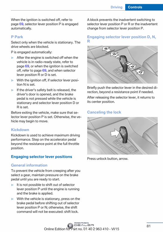
When the ignition is switched off, refer topage 69, selector lever position P is engagedautomatically.
P ParkSelect only when the vehicle is stationary. Thedrive wheels are blocked.P is engaged automatically:▷ After the engine is switched off when the
vehicle is in radio-ready state, refer topage 69, or when the ignition is switchedoff, refer to page 69, and when selectorlever position R or D is set.
▷ With the ignition off, if selector lever posi‐tion N is set.
▷ If the driver's safety belt is released, thedriver's door is opened, and the brakepedal is not pressed while the vehicle isstationary and selector lever position D orR is set.
Before exiting the vehicle, make sure that se‐lector lever position P is set. Otherwise, the ve‐hicle may begin to move.
KickdownKickdown is used to achieve maximum drivingperformance. Step on the accelerator pedalbeyond the resistance point at the full throttleposition.
Engaging selector lever positions
General informationTo prevent the vehicle from creeping after youselect a gear, maintain pressure on the brakepedal until you are ready to start.▷ It is not possible to shift out of selector
lever position P until the engine is runningand the brake is applied.
▷ With the vehicle is stationary, press on thebrake pedal before shifting out of selectorlever position P or N; otherwise, the shiftcommand will not be executed: shift lock.
A block prevents the inadvertent switching toselector lever position P or R or the inadvertentchange from selector lever position P.
Engaging selector lever position D, N,R
Briefly push the selector lever in the desired di‐rection, beyond a resistance point if needed.After releasing the selector lever, it returns toits center position.
Canceling the lock
Press unlock button, arrow.
Seite 81
Driving Controls
81Online Edition for Part no. 01 40 2 963 410 - VI/15
Information Provided by:
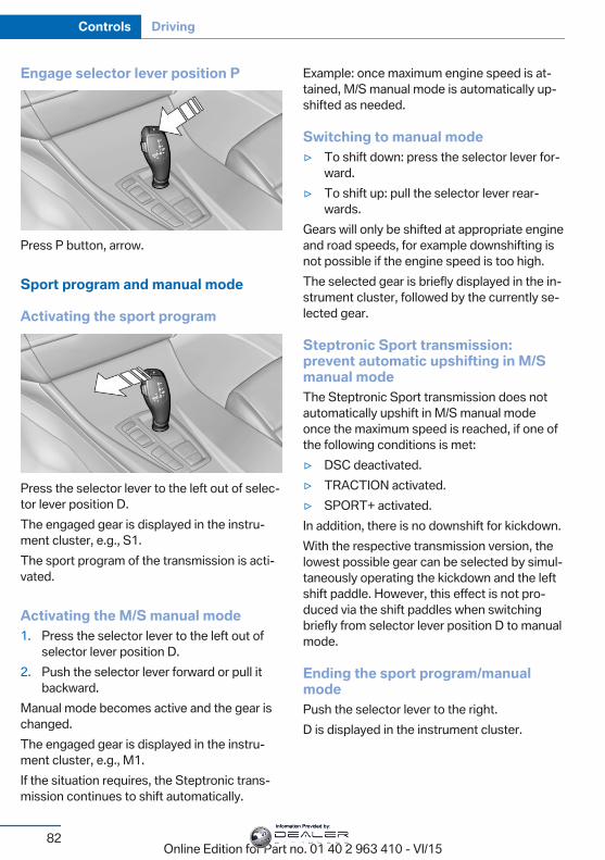
Engage selector lever position P
Press P button, arrow.
Sport program and manual mode
Activating the sport program
Press the selector lever to the left out of selec‐tor lever position D.The engaged gear is displayed in the instru‐ment cluster, e.g., S1.The sport program of the transmission is acti‐vated.
Activating the M/S manual mode1. Press the selector lever to the left out of
selector lever position D.2. Push the selector lever forward or pull it
backward.Manual mode becomes active and the gear ischanged.The engaged gear is displayed in the instru‐ment cluster, e.g., M1.If the situation requires, the Steptronic trans‐mission continues to shift automatically.
Example: once maximum engine speed is at‐tained, M/S manual mode is automatically up‐shifted as needed.
Switching to manual mode▷ To shift down: press the selector lever for‐
ward.▷ To shift up: pull the selector lever rear‐
wards.Gears will only be shifted at appropriate engineand road speeds, for example downshifting isnot possible if the engine speed is too high.The selected gear is briefly displayed in the in‐strument cluster, followed by the currently se‐lected gear.
Steptronic Sport transmission:prevent automatic upshifting in M/Smanual modeThe Steptronic Sport transmission does notautomatically upshift in M/S manual modeonce the maximum speed is reached, if one ofthe following conditions is met:▷ DSC deactivated.▷ TRACTION activated.▷ SPORT+ activated.In addition, there is no downshift for kickdown.With the respective transmission version, thelowest possible gear can be selected by simul‐taneously operating the kickdown and the leftshift paddle. However, this effect is not pro‐duced via the shift paddles when switchingbriefly from selector lever position D to manualmode.
Ending the sport program/manualmodePush the selector lever to the right.D is displayed in the instrument cluster.
Seite 82
Controls Driving
82Online Edition for Part no. 01 40 2 963 410 - VI/15
Information Provided by:
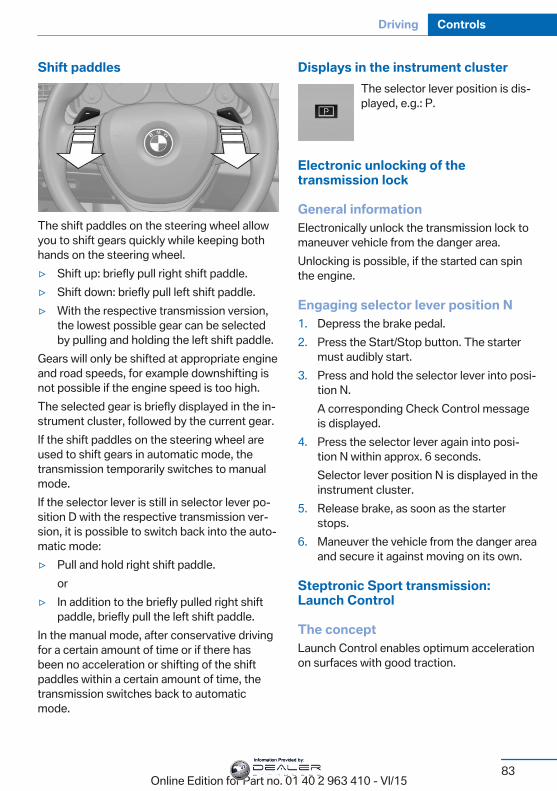
Shift paddles
The shift paddles on the steering wheel allowyou to shift gears quickly while keeping bothhands on the steering wheel.▷ Shift up: briefly pull right shift paddle.▷ Shift down: briefly pull left shift paddle.▷ With the respective transmission version,
the lowest possible gear can be selectedby pulling and holding the left shift paddle.
Gears will only be shifted at appropriate engineand road speeds, for example downshifting isnot possible if the engine speed is too high.The selected gear is briefly displayed in the in‐strument cluster, followed by the current gear.If the shift paddles on the steering wheel areused to shift gears in automatic mode, thetransmission temporarily switches to manualmode.If the selector lever is still in selector lever po‐sition D with the respective transmission ver‐sion, it is possible to switch back into the auto‐matic mode:▷ Pull and hold right shift paddle.
or▷ In addition to the briefly pulled right shift
paddle, briefly pull the left shift paddle.In the manual mode, after conservative drivingfor a certain amount of time or if there hasbeen no acceleration or shifting of the shiftpaddles within a certain amount of time, thetransmission switches back to automaticmode.
Displays in the instrument clusterThe selector lever position is dis‐played, e.g.: P.
Electronic unlocking of thetransmission lock
General informationElectronically unlock the transmission lock tomaneuver vehicle from the danger area.Unlocking is possible, if the started can spinthe engine.
Engaging selector lever position N1. Depress the brake pedal.2. Press the Start/Stop button. The starter
must audibly start.3. Press and hold the selector lever into posi‐
tion N.A corresponding Check Control messageis displayed.
4. Press the selector lever again into posi‐tion N within approx. 6 seconds.Selector lever position N is displayed in theinstrument cluster.
5. Release brake, as soon as the starterstops.
6. Maneuver the vehicle from the danger areaand secure it against moving on its own.
Steptronic Sport transmission:Launch Control
The conceptLaunch Control enables optimum accelerationon surfaces with good traction.
Seite 83
Driving Controls
83Online Edition for Part no. 01 40 2 963 410 - VI/15
Information Provided by:
General informationThe use of Launch Control causes prematurecomponent wear since this function representsa very heavy load for the vehicle.Do not use Launch Control during the break-in,refer to page 192, period.To increase vehicle stability, activate DSCagain as soon as possible.An experienced driver may be able to achievebetter acceleration values in DSC OFF mode.
RequirementsLaunch Control is available when the engine iswarmed up, that is, after uninterrupted drivingof at least 6 miles/10 km.To start with Launch Control do not steer thesteering wheel.
Start with launch controlWhile the engine is running:
1. Press button or select Sport+ withthe Driving Dynamics Control.TRACTION is displayed in the instrumentcluster and the indicator lamp for DSC OFFlights up.
2. Engage selector lever position S.3. With the left foot, forcefully press down on
the brake.4. Press and hold down the accelerator pedal
beyond the resistance point at the fullthrottle position, kickdown.A flag symbol is displayed in the instru‐ment cluster.
5. The starting engine speed adjusts. Within3 seconds, release the brake.
Before using Launch Control, allow the trans‐mission to cool down for approx. 5 minutes.Launch Control adjusts to the surroundingconditions, e.g., wet pavement, when usedagain.
Seite 84
Controls Driving
84Online Edition for Part no. 01 40 2 963 410 - VI/15
Information Provided by:
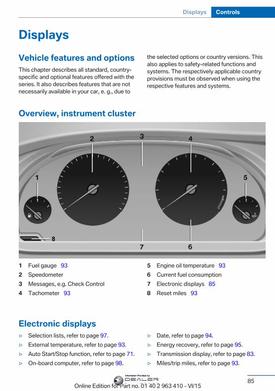
DisplaysVehicle features and optionsThis chapter describes all standard, country-specific and optional features offered with theseries. It also describes features that are notnecessarily available in your car, e. g., due to
the selected options or country versions. Thisalso applies to safety-related functions andsystems. The respectively applicable countryprovisions must be observed when using therespective features and systems.
Overview, instrument cluster
1 Fuel gauge 932 Speedometer3 Messages, e.g. Check Control4 Tachometer 93
5 Engine oil temperature 936 Current fuel consumption7 Electronic displays 858 Reset miles 93
Electronic displays▷ Selection lists, refer to page 97.▷ External temperature, refer to page 93.▷ Auto Start/Stop function, refer to page 71.▷ On-board computer, refer to page 98.
▷ Date, refer to page 94.▷ Energy recovery, refer to page 95.▷ Transmission display, refer to page 83.▷ Miles/trip miles, refer to page 93.
Seite 85
Displays Controls
85Online Edition for Part no. 01 40 2 963 410 - VI/15
Information Provided by:
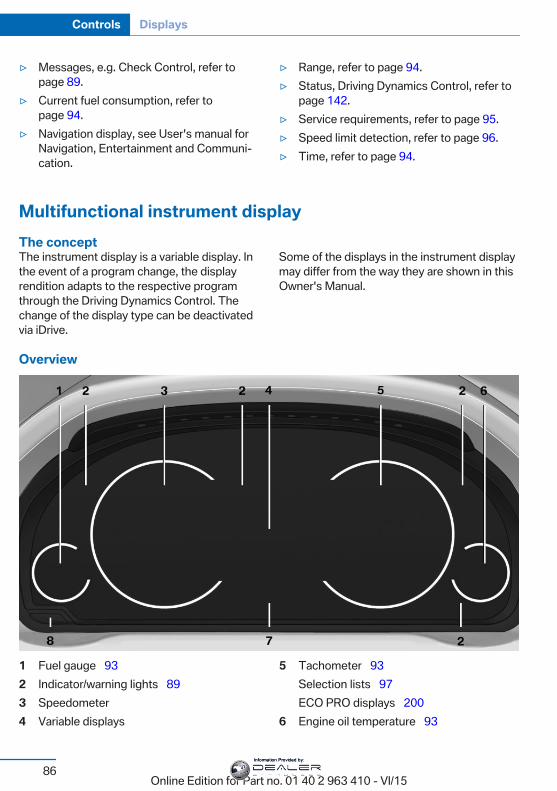
▷ Messages, e.g. Check Control, refer topage 89.
▷ Current fuel consumption, refer topage 94.
▷ Navigation display, see User's manual forNavigation, Entertainment and Communi‐cation.
▷ Range, refer to page 94.▷ Status, Driving Dynamics Control, refer to
page 142.▷ Service requirements, refer to page 95.▷ Speed limit detection, refer to page 96.▷ Time, refer to page 94.
Multifunctional instrument displayThe conceptThe instrument display is a variable display. Inthe event of a program change, the displayrendition adapts to the respective programthrough the Driving Dynamics Control. Thechange of the display type can be deactivatedvia iDrive.
Some of the displays in the instrument displaymay differ from the way they are shown in thisOwner's Manual.
Overview
1 Fuel gauge 932 Indicator/warning lights 893 Speedometer4 Variable displays
5 Tachometer 93Selection lists 97ECO PRO displays 200
6 Engine oil temperature 93
Seite 86
Controls Displays
86Online Edition for Part no. 01 40 2 963 410 - VI/15
Information Provided by:
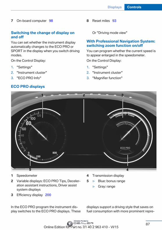
7 On-board computer 98 8 Reset miles 93
Switching the change of display onand offYou can set whether the instrument displayautomatically changes to the ECO PRO orSPORT in the display when you switch drivingmodes.On the Control Display:
1. "Settings"2. "Instrument cluster"3. "ECO PRO Info"
Or "Driving mode view"
With Professional Navigation System:switching zoom function on/offYou can program whether the current speed isto appear enlarged in the speedometer.On the Control Display:
1. "Settings"2. "Instrument cluster"3. "Magnifier function"
ECO PRO displays
1 Speedometer2 Variable displays: ECO PRO Tips, Deceler‐
ation assistant instructions, Driver assistsystem displays
3 Efficiency display 200
4 Transmission display5 ▷ Blue: bonus range
▷ Gray: range
In the ECO PRO program the instrument dis‐play switches to the ECO PRO displays. These
displays support a driving style that saves onfuel consumption with more prominent repre‐
Seite 87
Displays Controls
87Online Edition for Part no. 01 40 2 963 410 - VI/15
Information Provided by:
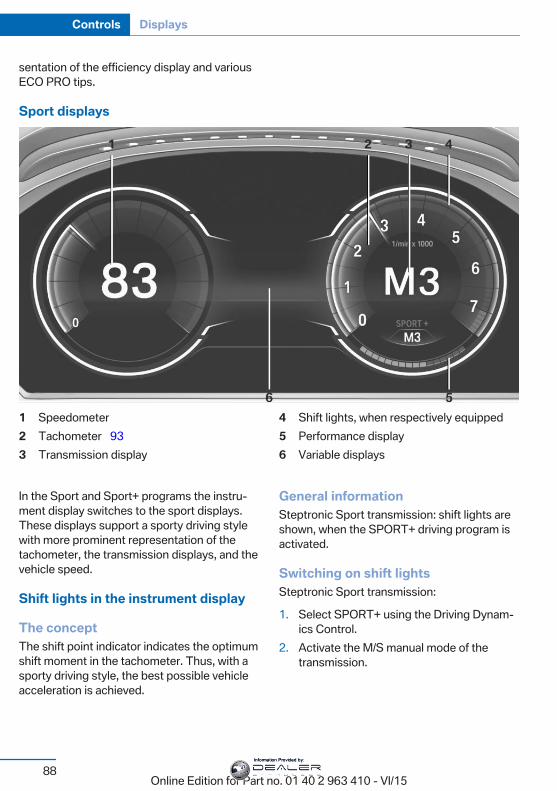
sentation of the efficiency display and variousECO PRO tips.
Sport displays
1 Speedometer2 Tachometer 933 Transmission display
4 Shift lights, when respectively equipped5 Performance display6 Variable displays
In the Sport and Sport+ programs the instru‐ment display switches to the sport displays.These displays support a sporty driving stylewith more prominent representation of thetachometer, the transmission displays, and thevehicle speed.
Shift lights in the instrument display
The conceptThe shift point indicator indicates the optimumshift moment in the tachometer. Thus, with asporty driving style, the best possible vehicleacceleration is achieved.
General informationSteptronic Sport transmission: shift lights areshown, when the SPORT+ driving program isactivated.
Switching on shift lightsSteptronic Sport transmission:
1. Select SPORT+ using the Driving Dynam‐ics Control.
2. Activate the M/S manual mode of thetransmission.
Seite 88
Controls Displays
88Online Edition for Part no. 01 40 2 963 410 - VI/15
Information Provided by:
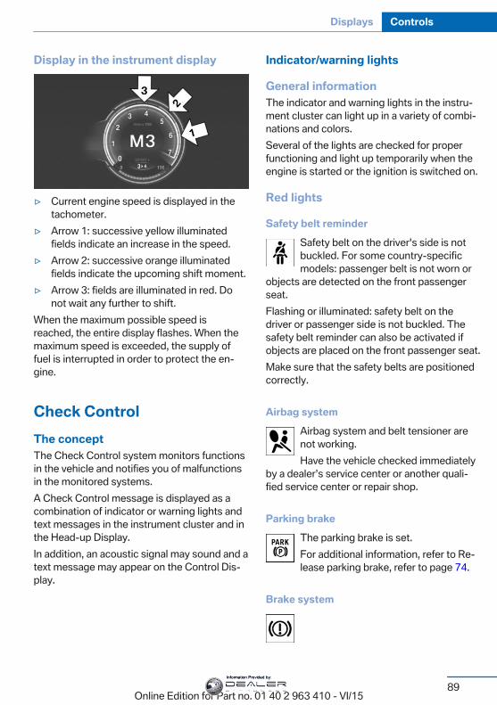
Display in the instrument display
▷ Current engine speed is displayed in thetachometer.
▷ Arrow 1: successive yellow illuminatedfields indicate an increase in the speed.
▷ Arrow 2: successive orange illuminatedfields indicate the upcoming shift moment.
▷ Arrow 3: fields are illuminated in red. Donot wait any further to shift.
When the maximum possible speed isreached, the entire display flashes. When themaximum speed is exceeded, the supply offuel is interrupted in order to protect the en‐gine.
Check ControlThe conceptThe Check Control system monitors functionsin the vehicle and notifies you of malfunctionsin the monitored systems.A Check Control message is displayed as acombination of indicator or warning lights andtext messages in the instrument cluster and inthe Head-up Display.In addition, an acoustic signal may sound and atext message may appear on the Control Dis‐play.
Indicator/warning lights
General informationThe indicator and warning lights in the instru‐ment cluster can light up in a variety of combi‐nations and colors.Several of the lights are checked for properfunctioning and light up temporarily when theengine is started or the ignition is switched on.
Red lights
Safety belt reminderSafety belt on the driver's side is notbuckled. For some country-specificmodels: passenger belt is not worn or
objects are detected on the front passengerseat.Flashing or illuminated: safety belt on thedriver or passenger side is not buckled. Thesafety belt reminder can also be activated ifobjects are placed on the front passenger seat.Make sure that the safety belts are positionedcorrectly.
Airbag systemAirbag system and belt tensioner arenot working.Have the vehicle checked immediately
by a dealer’s service center or another quali‐fied service center or repair shop.
Parking brakeThe parking brake is set.For additional information, refer to Re‐lease parking brake, refer to page 74.
Brake system
Seite 89
Displays Controls
89Online Edition for Part no. 01 40 2 963 410 - VI/15
Information Provided by:
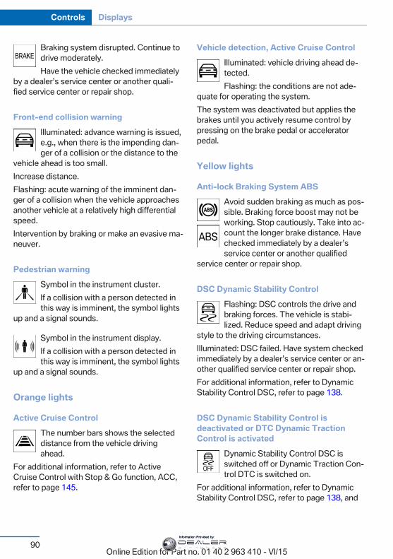
Braking system disrupted. Continue todrive moderately.Have the vehicle checked immediately
by a dealer’s service center or another quali‐fied service center or repair shop.
Front-end collision warningIlluminated: advance warning is issued,e.g., when there is the impending dan‐ger of a collision or the distance to the
vehicle ahead is too small.Increase distance.Flashing: acute warning of the imminent dan‐ger of a collision when the vehicle approachesanother vehicle at a relatively high differentialspeed.Intervention by braking or make an evasive ma‐neuver.
Pedestrian warningSymbol in the instrument cluster.If a collision with a person detected inthis way is imminent, the symbol lights
up and a signal sounds.
Symbol in the instrument display.If a collision with a person detected inthis way is imminent, the symbol lights
up and a signal sounds.
Orange lights
Active Cruise ControlThe number bars shows the selecteddistance from the vehicle drivingahead.
For additional information, refer to ActiveCruise Control with Stop & Go function, ACC,refer to page 145.
Vehicle detection, Active Cruise ControlIlluminated: vehicle driving ahead de‐tected.Flashing: the conditions are not ade‐
quate for operating the system.The system was deactivated but applies thebrakes until you actively resume control bypressing on the brake pedal or acceleratorpedal.
Yellow lights
Anti-lock Braking System ABSAvoid sudden braking as much as pos‐sible. Braking force boost may not beworking. Stop cautiously. Take into ac‐count the longer brake distance. Havechecked immediately by a dealer’sservice center or another qualified
service center or repair shop.
DSC Dynamic Stability ControlFlashing: DSC controls the drive andbraking forces. The vehicle is stabi‐lized. Reduce speed and adapt driving
style to the driving circumstances.Illuminated: DSC failed. Have system checkedimmediately by a dealer’s service center or an‐other qualified service center or repair shop.For additional information, refer to DynamicStability Control DSC, refer to page 138.
DSC Dynamic Stability Control isdeactivated or DTC Dynamic TractionControl is activated
Dynamic Stability Control DSC isswitched off or Dynamic Traction Con‐trol DTC is switched on.
For additional information, refer to DynamicStability Control DSC, refer to page 138, and
Seite 90
Controls Displays
90Online Edition for Part no. 01 40 2 963 410 - VI/15
Information Provided by:
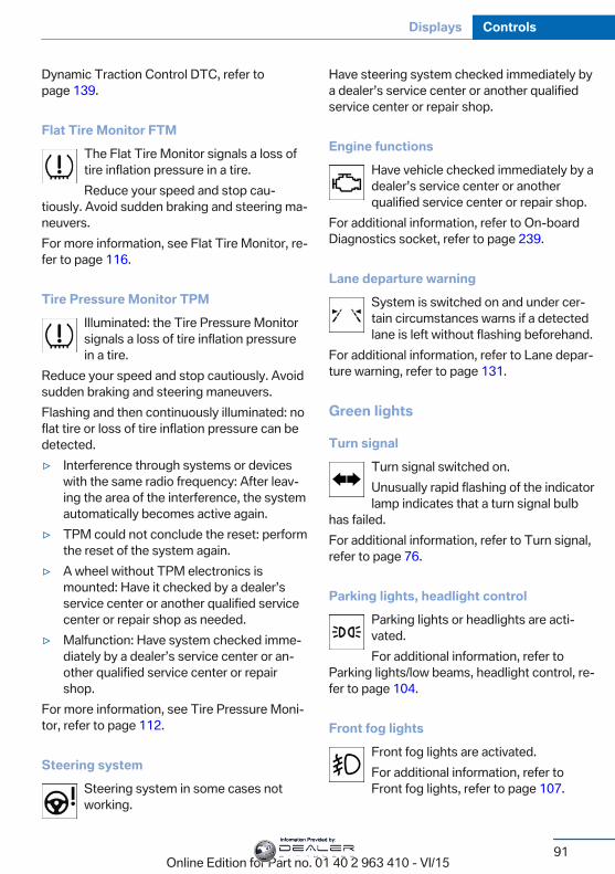
Dynamic Traction Control DTC, refer topage 139.
Flat Tire Monitor FTMThe Flat Tire Monitor signals a loss oftire inflation pressure in a tire.Reduce your speed and stop cau‐
tiously. Avoid sudden braking and steering ma‐neuvers.For more information, see Flat Tire Monitor, re‐fer to page 116.
Tire Pressure Monitor TPMIlluminated: the Tire Pressure Monitorsignals a loss of tire inflation pressurein a tire.
Reduce your speed and stop cautiously. Avoidsudden braking and steering maneuvers.Flashing and then continuously illuminated: noflat tire or loss of tire inflation pressure can bedetected.▷ Interference through systems or devices
with the same radio frequency: After leav‐ing the area of the interference, the systemautomatically becomes active again.
▷ TPM could not conclude the reset: performthe reset of the system again.
▷ A wheel without TPM electronics ismounted: Have it checked by a dealer’sservice center or another qualified servicecenter or repair shop as needed.
▷ Malfunction: Have system checked imme‐diately by a dealer’s service center or an‐other qualified service center or repairshop.
For more information, see Tire Pressure Moni‐tor, refer to page 112.
Steering systemSteering system in some cases notworking.
Have steering system checked immediately bya dealer’s service center or another qualifiedservice center or repair shop.
Engine functionsHave vehicle checked immediately by adealer’s service center or anotherqualified service center or repair shop.
For additional information, refer to On-boardDiagnostics socket, refer to page 239.
Lane departure warningSystem is switched on and under cer‐tain circumstances warns if a detectedlane is left without flashing beforehand.
For additional information, refer to Lane depar‐ture warning, refer to page 131.
Green lights
Turn signalTurn signal switched on.Unusually rapid flashing of the indicatorlamp indicates that a turn signal bulb
has failed.For additional information, refer to Turn signal,refer to page 76.
Parking lights, headlight controlParking lights or headlights are acti‐vated.For additional information, refer to
Parking lights/low beams, headlight control, re‐fer to page 104.
Front fog lightsFront fog lights are activated.For additional information, refer toFront fog lights, refer to page 107.
Seite 91
Displays Controls
91Online Edition for Part no. 01 40 2 963 410 - VI/15
Information Provided by:
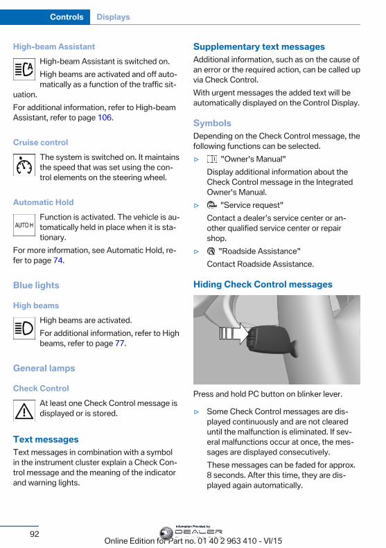
High-beam AssistantHigh-beam Assistant is switched on.High beams are activated and off auto‐matically as a function of the traffic sit‐
uation.For additional information, refer to High-beamAssistant, refer to page 106.
Cruise controlThe system is switched on. It maintainsthe speed that was set using the con‐trol elements on the steering wheel.
Automatic HoldFunction is activated. The vehicle is au‐tomatically held in place when it is sta‐tionary.
For more information, see Automatic Hold, re‐fer to page 74.
Blue lights
High beamsHigh beams are activated.For additional information, refer to Highbeams, refer to page 77.
General lamps
Check ControlAt least one Check Control message isdisplayed or is stored.
Text messagesText messages in combination with a symbolin the instrument cluster explain a Check Con‐trol message and the meaning of the indicatorand warning lights.
Supplementary text messagesAdditional information, such as on the cause ofan error or the required action, can be called upvia Check Control.With urgent messages the added text will beautomatically displayed on the Control Display.
SymbolsDepending on the Check Control message, thefollowing functions can be selected.▷ "Owner's Manual"
Display additional information about theCheck Control message in the IntegratedOwner's Manual.
▷ "Service request"Contact a dealer’s service center or an‐other qualified service center or repairshop.
▷ "Roadside Assistance"Contact Roadside Assistance.
Hiding Check Control messages
Press and hold PC button on blinker lever.
▷ Some Check Control messages are dis‐played continuously and are not cleareduntil the malfunction is eliminated. If sev‐eral malfunctions occur at once, the mes‐sages are displayed consecutively.These messages can be faded for approx.8 seconds. After this time, they are dis‐played again automatically.
Seite 92
Controls Displays
92Online Edition for Part no. 01 40 2 963 410 - VI/15
Information Provided by:
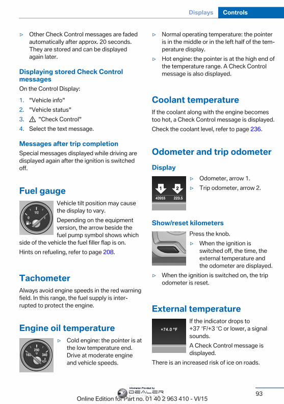
▷ Other Check Control messages are fadedautomatically after approx. 20 seconds.They are stored and can be displayedagain later.
Displaying stored Check ControlmessagesOn the Control Display:
1. "Vehicle info"2. "Vehicle status"3. "Check Control"4. Select the text message.
Messages after trip completionSpecial messages displayed while driving aredisplayed again after the ignition is switchedoff.
Fuel gaugeVehicle tilt position may causethe display to vary.Depending on the equipmentversion, the arrow beside thefuel pump symbol shows which
side of the vehicle the fuel filler flap is on.Hints on refueling, refer to page 208.
TachometerAlways avoid engine speeds in the red warningfield. In this range, the fuel supply is inter‐rupted to protect the engine.
Engine oil temperature▷ Cold engine: the pointer is at
the low temperature end.Drive at moderate engineand vehicle speeds.
▷ Normal operating temperature: the pointeris in the middle or in the left half of the tem‐perature display.
▷ Hot engine: the pointer is at the high end ofthe temperature range. A Check Controlmessage is also displayed.
Coolant temperatureIf the coolant along with the engine becomestoo hot, a Check Control message is displayed.Check the coolant level, refer to page 236.
Odometer and trip odometerDisplay
▷ Odometer, arrow 1.▷ Trip odometer, arrow 2.
Show/reset kilometersPress the knob.▷ When the ignition is
switched off, the time, theexternal temperature andthe odometer are displayed.
▷ When the ignition is switched on, the tripodometer is reset.
External temperatureIf the indicator drops to+37 ℉/+3 ℃ or lower, a signalsounds.A Check Control message isdisplayed.
There is an increased risk of ice on roads.
Seite 93
Displays Controls
93Online Edition for Part no. 01 40 2 963 410 - VI/15
Information Provided by:
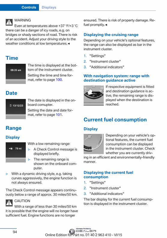
WARNINGEven at temperatures above +37 ℉/+3 ℃
there can be a danger of icy roads, e.g. onbridges or shady sections of road. There is riskof an accident. Adjust your driving style to theweather conditions at low temperatures.◀
TimeThe time is displayed at the bot‐tom of the instrument cluster.Setting the time and time for‐mat, refer to page 100.
DateThe date is displayed in the on-board comupter.Setting the date and date for‐mat, refer to page 101.
RangeDisplay
With a low remaining range:▷ A Check Control message is
displayed briefly.▷ The remaining range is
shown on the onboard com‐puter.
▷ With a dynamic driving style, e.g. takingcurves aggressively, the engine function isnot always ensured.
The Check Control message appears continu‐ously below a range of approx. 30 miles/50 km.
CAUTIONWith a range of less than 30 miles/50 km
it is possible that the engine will no longer havesufficient fuel. Engine functions are no longer
ensured. There is risk of property damage. Re‐fuel promptly.◀
Displaying the cruising rangeDepending on your vehicle's optional features,the range can also be displayed as bar in theinstrument cluster.
1. "Settings"2. "Instrument cluster"3. "Additional indicators"
With navigation system: range withdestination guidance active
If respective equipment is fittedand destination guidance is ac‐tive, the remaining range is dis‐played when the destination isreached.
Current fuel consumptionDisplay
Depending on your vehicle's op‐tional features, the current fuelconsumption can be displayedin the instrument cluster. Checkwhether you are currently driv‐
ing in an efficient and environmentally-friendlymanner.
Displaying the current fuelconsumption1. "Settings"2. "Instrument cluster"3. "Additional indicators"The bar display for the current fuel consump‐tion is displayed in the instrument cluster.
Seite 94
Controls Displays
94Online Edition for Part no. 01 40 2 963 410 - VI/15
Information Provided by:
Energy recoveryDisplay
The kinetic energy of the vehicleis converted to electrical energywhile coasting. The vehicle bat‐tery is partially charged and fuelconsumption can be reduced.
Service requirementsThe conceptAfter the ignition is turned on the instrumentcluster briefly displays available driving dis‐tance or time to the next scheduled mainte‐nance.A service advisor can read out the currentservice requirements from your remote con‐trol.
Display
Detailed information on servicerequirementsMore information on the scope of service re‐quired can be displayed on the Control Dis‐play.
1. "Vehicle info"2. "Vehicle status"3. "Service required"
Required maintenance procedures and le‐gally mandated inspections are displayed.
4. Select an entry to call up detailed informa‐tion.
Symbols
Sym‐bols
Description
No service is currently required.
The deadline for scheduled mainte‐nance or a legally mandated inspec‐tion is approaching.
The service deadline has alreadypassed.
Entering appointment datesEnter the dates for the required inspections.Make sure that the vehicle's date and time areset correctly.On the Control Display:
1. "Vehicle info"2. "Vehicle status"3. "Service required"4. "§ Vehicle inspection"5. "Date:"6. Adjust the settings.7. Confirm.
The entered date is stored.
Automatic Service RequestData regarding the service status or legallymandated vehicle inspections are automati‐cally transmitted to your dealer’s service cen‐ter before a service due date.You can check when your dealer’s service cen‐ter was notified.On the Control Display:
1. "Vehicle info"2. "Vehicle status"3. Open "Options".4. "Last Service Request"
Seite 95
Displays Controls
95Online Edition for Part no. 01 40 2 963 410 - VI/15
Information Provided by:
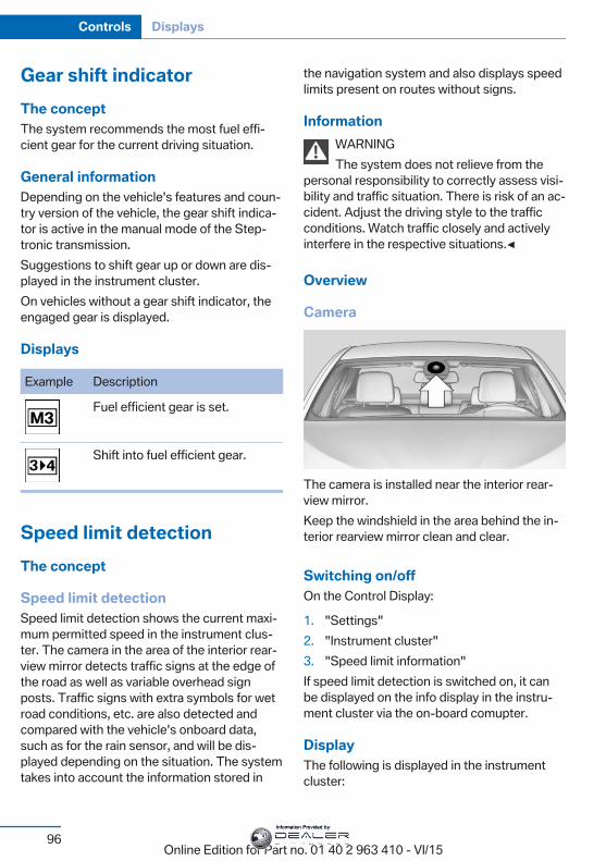
Gear shift indicatorThe conceptThe system recommends the most fuel effi‐cient gear for the current driving situation.
General informationDepending on the vehicle's features and coun‐try version of the vehicle, the gear shift indica‐tor is active in the manual mode of the Step‐tronic transmission.Suggestions to shift gear up or down are dis‐played in the instrument cluster.On vehicles without a gear shift indicator, theengaged gear is displayed.
Displays
Example Description
Fuel efficient gear is set.
Shift into fuel efficient gear.
Speed limit detectionThe concept
Speed limit detectionSpeed limit detection shows the current maxi‐mum permitted speed in the instrument clus‐ter. The camera in the area of the interior rear‐view mirror detects traffic signs at the edge ofthe road as well as variable overhead signposts. Traffic signs with extra symbols for wetroad conditions, etc. are also detected andcompared with the vehicle's onboard data,such as for the rain sensor, and will be dis‐played depending on the situation. The systemtakes into account the information stored in
the navigation system and also displays speedlimits present on routes without signs.
InformationWARNINGThe system does not relieve from the
personal responsibility to correctly assess visi‐bility and traffic situation. There is risk of an ac‐cident. Adjust the driving style to the trafficconditions. Watch traffic closely and activelyinterfere in the respective situations.◀
Overview
Camera
The camera is installed near the interior rear‐view mirror.Keep the windshield in the area behind the in‐terior rearview mirror clean and clear.
Switching on/offOn the Control Display:
1. "Settings"2. "Instrument cluster"3. "Speed limit information"If speed limit detection is switched on, it canbe displayed on the info display in the instru‐ment cluster via the on-board comupter.
DisplayThe following is displayed in the instrumentcluster:
Seite 96
Controls Displays
96Online Edition for Part no. 01 40 2 963 410 - VI/15
Information Provided by:
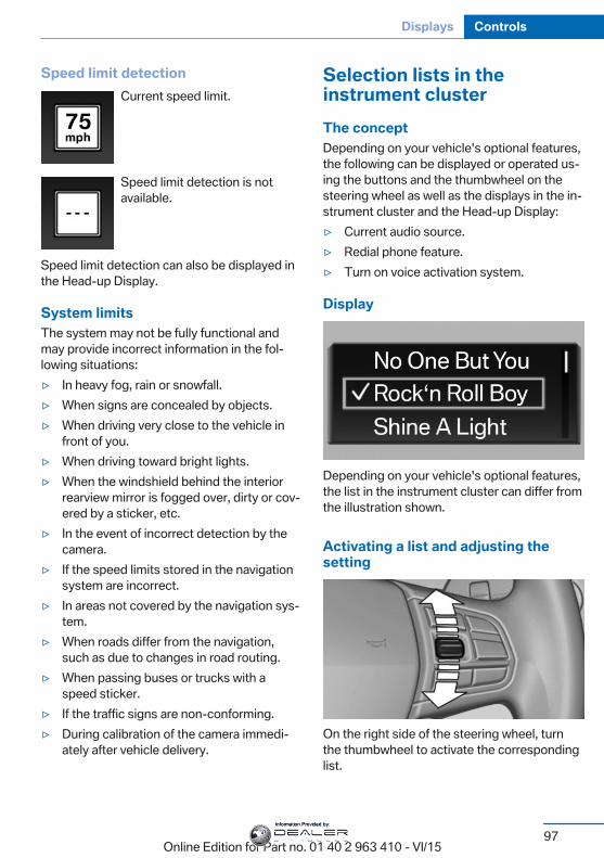
Speed limit detectionCurrent speed limit.
Speed limit detection is notavailable.
Speed limit detection can also be displayed inthe Head-up Display.
System limitsThe system may not be fully functional andmay provide incorrect information in the fol‐lowing situations:▷ In heavy fog, rain or snowfall.▷ When signs are concealed by objects.▷ When driving very close to the vehicle in
front of you.▷ When driving toward bright lights.▷ When the windshield behind the interior
rearview mirror is fogged over, dirty or cov‐ered by a sticker, etc.
▷ In the event of incorrect detection by thecamera.
▷ If the speed limits stored in the navigationsystem are incorrect.
▷ In areas not covered by the navigation sys‐tem.
▷ When roads differ from the navigation,such as due to changes in road routing.
▷ When passing buses or trucks with aspeed sticker.
▷ If the traffic signs are non-conforming.▷ During calibration of the camera immedi‐
ately after vehicle delivery.
Selection lists in theinstrument clusterThe conceptDepending on your vehicle's optional features,the following can be displayed or operated us‐ing the buttons and the thumbwheel on thesteering wheel as well as the displays in the in‐strument cluster and the Head-up Display:▷ Current audio source.▷ Redial phone feature.▷ Turn on voice activation system.
Display
Depending on your vehicle's optional features,the list in the instrument cluster can differ fromthe illustration shown.
Activating a list and adjusting thesetting
On the right side of the steering wheel, turnthe thumbwheel to activate the correspondinglist.
Seite 97
Displays Controls
97Online Edition for Part no. 01 40 2 963 410 - VI/15
Information Provided by:
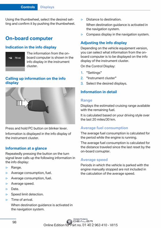
Using the thumbwheel, select the desired set‐ting and confirm it by pushing the thumbwheel.
On-board computerIndication in the info display
The information from the on-board computer is shown in theinfo display in the instrumentcluster.
Calling up information on the infodisplay
Press and hold PC button on blinker lever.Information is displayed in the info display ofthe instrument cluster.
Information at a glanceRepeatedly pressing the button on the turnsignal lever calls up the following information inthe info display:▷ Range.▷ Average consumption, fuel.▷ Average consumption, fuel.▷ Average speed.▷ Date.▷ Speed limit detection.▷ Time of arrival.
When destination guidance is activated inthe navigation system.
▷ Distance to destination.When destination guidance is activated inthe navigation system.
▷ Compass display in the navigation system.
Adjusting the info displayDepending on the vehicle equipment version,you can select what information from the on-board computer is to be displayed on the infodisplay of the instrument cluster.On the Control Display:
1. "Settings"2. "Instrument cluster"3. Select the desired displays.
Information in detail
RangeDisplays the estimated cruising range availablewith the remaining fuel.It is calculated based on your driving style overthe last 20 miles/30 km.
Average fuel consumptionThe average fuel consumption is calculated forthe period while the engine is running.The average fuel consumption is calculated forthe distance traveled since the last reset by theon-board comupter.
Average speedPeriods in which the vehicle is parked with theengine manually stopped are not included inthe calculation of the average speed.
Seite 98
Controls Displays
98Online Edition for Part no. 01 40 2 963 410 - VI/15
Information Provided by:
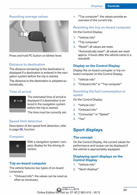
Resetting average values
Press and hold PC button on blinker lever.
Distance to destinationThe distance remaining to the destination isdisplayed if a destination is entered in the navi‐gation system before the trip is started.The distance to the destination is adopted au‐tomatically.
Time of arrivalThe estimated time of arrival isdisplayed if a destination is en‐tered in the navigation systembefore the trip is started.The time must be correctly set.
Speed limit detectionDescription of the speed limit detection, referto page 96, function.
CompassWith a navigation system: com‐pass display for the driving di‐rection.
Trip on-board computerThe vehicle features two types of on-boardcomputers.▷ "Onboard info": the values can be reset as
often as necessary.
▷ "Trip computer": the values provide anoverview of the current trip.
Resetting the trip on-board computerOn the Control Display:
1. "Vehicle info"2. "Trip computer"3. "Reset": all values are reset.
"Automatically reset": all values are resetapprox. 4 hours after the vehicle came to astandstill.
Display on the Control DisplayDisplay the on-board comupter or trip on-board computer on the Control Display.
1. "Vehicle info"2. "Onboard info" or "Trip computer"
Resetting the fuel consumption orspeedOn the Control Display:
1. "Vehicle info"2. "Onboard info"3. "Consumpt." or "Speed"4. "Yes"
Sport displaysThe conceptOn the Control Display, the current values forperformance and torque can be displayed ifthe vehicle is appropriately equipped.
Displaying sport displays on theControl Display1. "Vehicle info"2. "Sport displays"
Seite 99
Displays Controls
99Online Edition for Part no. 01 40 2 963 410 - VI/15
Information Provided by:
Speed warningThe conceptDisplays a speed, when reached, should causea warning to be issued.The warning is repeated if the vehicle speeddrops below the set speed once by at least3 mph/5 km/h.
Displaying, setting or changing thespeed warningOn the Control Display:
1. "Settings"2. "Speed"3. "Warning at:"4. Turn the controller until the desired speed
is displayed.5. Press the controller.Speed warning is stored.
Activating/deactivating the speedwarningOn the Control Display:
1. "Settings"2. "Speed"3. "Warning"4. Press the controller.
Setting your current speed as thespeed warningOn the Control Display:
1. "Settings"2. "Speed"3. "Select current speed"4. Press the controller.
The current vehicle speed is stored as thespeed warning.
Settings on the ControlDisplayTime
Setting the time zone1. "Settings"2. "Time/Date"3. "Time zone:"4. Select the desired time zone.The time zone is stored.
Setting the time1. "Settings"2. "Time/Date"3. "Time:"4. Turn the controller until the desired hours
are displayed.5. Press the controller.6. Turn the controller until the desired mi‐
nutes are displayed.7. Press the controller.The time is stored.
Setting the time format1. "Settings"2. "Time/Date"3. "Format:"4. Select the desired format.The time format is stored.
Automatic time settingDepending on your vehicle's optional features,the time, date and, if needed, the time zone areupdated automatically.
1. "Settings"2. "Time/Date"3. "Auto time set"
Seite 100
Controls Displays
100Online Edition for Part no. 01 40 2 963 410 - VI/15
Information Provided by:
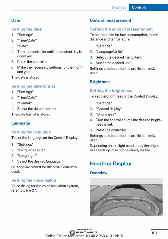
Date
Setting the date1. "Settings"2. "Time/Date"3. "Date:"4. Turn the controller until the desired day is
displayed.5. Press the controller.6. Make the necessary settings for the month
and year.The date is stored.
Setting the date format1. "Settings"2. "Time/Date"3. "Format:"4. Select the desired format.The date format is stored.
Language
Setting the languageTo set the language on the Control Display:
1. "Settings"2. "Language/Units"3. "Language:"4. Select the desired language.Settings are stored for the profile currentlyused.
Setting the voice dialogVoice dialog for the voice activation system,refer to page 27.
Units of measurement
Setting the units of measurementTo set the units for fuel consumption, route/distance and temperature:
1. "Settings"2. "Language/Units"3. Select the desired menu item.4. Select the desired unit.Settings are stored for the profile currentlyused.
Brightness
Setting the brightnessTo set the brightness of the Control Display:
1. "Settings"2. "Control display"3. "Brightness"4. Turn the controller until the desired bright‐
ness is set.5. Press the controller.Settings are stored for the profile currentlyused.Depending on the light conditions, the bright‐ness settings may not be clearly visible.
Head-up DisplayOverview
Seite 101
Displays Controls
101Online Edition for Part no. 01 40 2 963 410 - VI/15
Information Provided by:
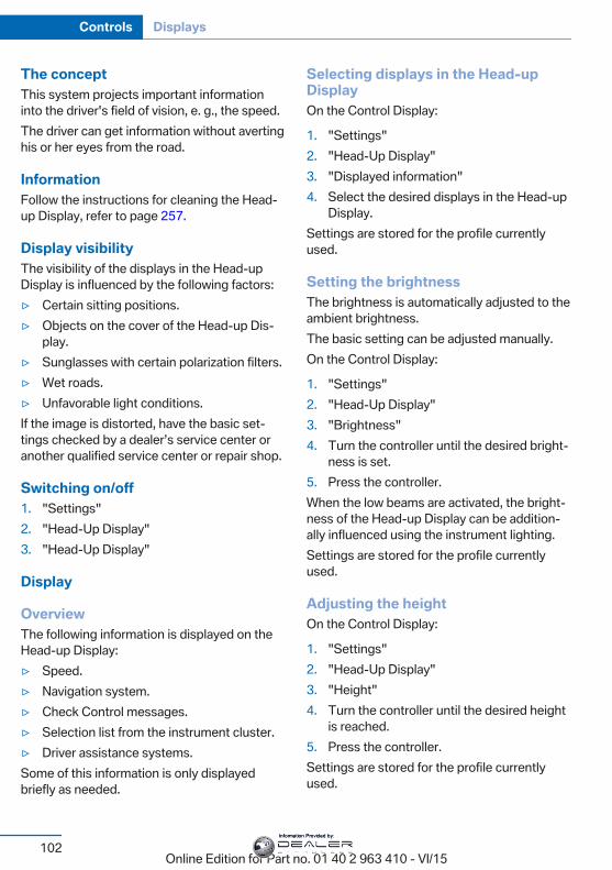
The conceptThis system projects important informationinto the driver's field of vision, e. g., the speed.The driver can get information without avertinghis or her eyes from the road.
InformationFollow the instructions for cleaning the Head-up Display, refer to page 257.
Display visibilityThe visibility of the displays in the Head-upDisplay is influenced by the following factors:▷ Certain sitting positions.▷ Objects on the cover of the Head-up Dis‐
play.▷ Sunglasses with certain polarization filters.▷ Wet roads.▷ Unfavorable light conditions.If the image is distorted, have the basic set‐tings checked by a dealer’s service center oranother qualified service center or repair shop.
Switching on/off1. "Settings"2. "Head-Up Display"3. "Head-Up Display"
Display
OverviewThe following information is displayed on theHead-up Display:▷ Speed.▷ Navigation system.▷ Check Control messages.▷ Selection list from the instrument cluster.▷ Driver assistance systems.Some of this information is only displayedbriefly as needed.
Selecting displays in the Head-upDisplayOn the Control Display:
1. "Settings"2. "Head-Up Display"3. "Displayed information"4. Select the desired displays in the Head-up
Display.Settings are stored for the profile currentlyused.
Setting the brightnessThe brightness is automatically adjusted to theambient brightness.The basic setting can be adjusted manually.On the Control Display:
1. "Settings"2. "Head-Up Display"3. "Brightness"4. Turn the controller until the desired bright‐
ness is set.5. Press the controller.When the low beams are activated, the bright‐ness of the Head-up Display can be addition‐ally influenced using the instrument lighting.Settings are stored for the profile currentlyused.
Adjusting the heightOn the Control Display:
1. "Settings"2. "Head-Up Display"3. "Height"4. Turn the controller until the desired height
is reached.5. Press the controller.Settings are stored for the profile currentlyused.
Seite 102
Controls Displays
102Online Edition for Part no. 01 40 2 963 410 - VI/15
Information Provided by:
Setting the rotationThe screen of the Head-up Display can be ro‐tated around its own axis.On the Control Display:
1. "Settings"2. "Head-Up Display"3. "Rotation"4. Turn the controller until the desired setting
is selected.5. Press the controller.Settings are stored for the profile currentlyused.
Special windshieldThe windshield is part of the system.The shape of the windshield makes it possibleto display a precise image.A film in the windshield prevents double im‐ages from being displayed.For this reason, it is strongly suggested tohave the special windshield replaced by adealer’s service center or another qualifiedservice center or repair shop.
Seite 103
Displays Controls
103Online Edition for Part no. 01 40 2 963 410 - VI/15
Information Provided by:
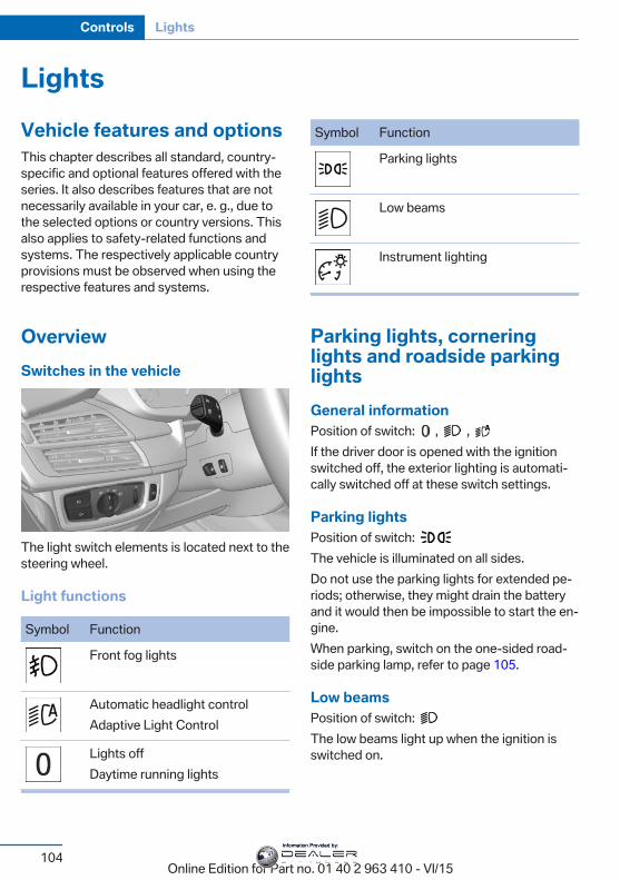
LightsVehicle features and optionsThis chapter describes all standard, country-specific and optional features offered with theseries. It also describes features that are notnecessarily available in your car, e. g., due tothe selected options or country versions. Thisalso applies to safety-related functions andsystems. The respectively applicable countryprovisions must be observed when using therespective features and systems.
OverviewSwitches in the vehicle
The light switch elements is located next to thesteering wheel.
Light functions
Symbol Function
Front fog lights
Automatic headlight controlAdaptive Light Control
Lights offDaytime running lights
Symbol Function
Parking lights
Low beams
Instrument lighting
Parking lights, corneringlights and roadside parkinglightsGeneral informationPosition of switch: , , If the driver door is opened with the ignitionswitched off, the exterior lighting is automati‐cally switched off at these switch settings.
Parking lightsPosition of switch: The vehicle is illuminated on all sides.Do not use the parking lights for extended pe‐riods; otherwise, they might drain the batteryand it would then be impossible to start the en‐gine.When parking, switch on the one-sided road‐side parking lamp, refer to page 105.
Low beamsPosition of switch: The low beams light up when the ignition isswitched on.
Seite 104
Controls Lights
104Online Edition for Part no. 01 40 2 963 410 - VI/15
Information Provided by:
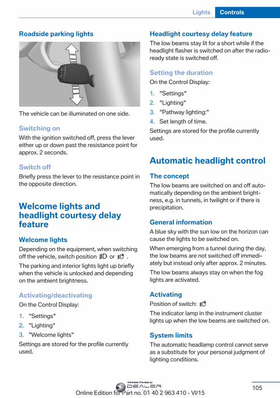
Roadside parking lights
The vehicle can be illuminated on one side.
Switching onWith the ignition switched off, press the levereither up or down past the resistance point forapprox. 2 seconds.
Switch offBriefly press the lever to the resistance point inthe opposite direction.
Welcome lights andheadlight courtesy delayfeatureWelcome lightsDepending on the equipment, when switchingoff the vehicle, switch position or .The parking and interior lights light up brieflywhen the vehicle is unlocked and dependingon the ambient brightness.
Activating/deactivatingOn the Control Display:
1. "Settings"2. "Lighting"3. "Welcome lights"Settings are stored for the profile currentlyused.
Headlight courtesy delay featureThe low beams stay lit for a short while if theheadlight flasher is switched on after the radio-ready state is switched off.
Setting the durationOn the Control Display:
1. "Settings"2. "Lighting"3. "Pathway lighting:"4. Set length of time.Settings are stored for the profile currentlyused.
Automatic headlight controlThe conceptThe low beams are switched on and off auto‐matically depending on the ambient bright‐ness, e.g. in tunnels, in twilight or if there isprecipitation.
General informationA blue sky with the sun low on the horizon cancause the lights to be switched on.When emerging from a tunnel during the day,the low beams are not switched off immedi‐ately but instead only after approx. 2 minutes.The low beams always stay on when the foglights are activated.
ActivatingPosition of switch: The indicator lamp in the instrument clusterlights up when the low beams are switched on.
System limitsThe automatic headlamp control cannot serveas a substitute for your personal judgment oflighting conditions.
Seite 105
Lights Controls
105Online Edition for Part no. 01 40 2 963 410 - VI/15
Information Provided by:
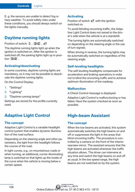
E. g. the sensors are unable to detect fog orhazy weather. To avoid safety risks underthese conditions, you should always switch onthe lights manually.
Daytime running lightsPosition of switch: , , The daytime running lights light up when theignition is switched on. After the ignition isswitched off, the parking lights light up in posi‐tion .
Activating/deactivatingIn some countries, daytime running lights aremandatory, so it may not be possible to deacti‐vate the daytime running lights.On the Control Display:
1. "Settings"2. "Lighting"3. "Daytime running lamps"Settings are stored for the profile currentlyused.
Adaptive Light ControlThe conceptAdaptive Light Control is a variable headlightcontrol system that enables dynamic illumina‐tion of the road surface.Depending on the steering angle and other pa‐rameters, the light from the headlight followsthe course of the road.In tight curves, e.g., on mountainous roads orwhen turning, an additional, corner-illuminatinglamp is switched on that lights up the inside ofthe curve when the vehicle is moving below acertain speed.
ActivatingPosition of switch with the ignitionswitched on.To avoid blinding oncoming traffic, the Adap‐tive Light Control does not swivel to the driv‐er's side when the vehicle is at a standstill.The turning lights are automatically switchedon depending on the steering angle or the useof turn signals.When driving in reverse, the turning lights maybe automatically switched on regardless of thesteering angle.
Self-leveling headlightsThe self-leveling headlights compensate foracceleration and braking operations in ordernot to blind the oncoming traffic and to achieveoptimum illumination of the roadway.
MalfunctionA Check Control message is displayed.Adaptive Light Control is malfunctioning or hasfailed. Have the system checked as soon aspossible.
High-beam AssistantThe conceptWhen the low beams are activated, this systemautomatically switches the high beams on andoff or suppresses the light in the areas thatblind oncoming traffic. The procedure is con‐trolled by a camera on the front of the interiorrearview mirror. The assistant ensures that thehigh beams are activated whenever the trafficsituation allows. The driver can intervene atany time and switch the high beams on and offas usual. In the low speed range, the highbeams are not switched on by the system.
Seite 106
Controls Lights
106Online Edition for Part no. 01 40 2 963 410 - VI/15
Information Provided by:
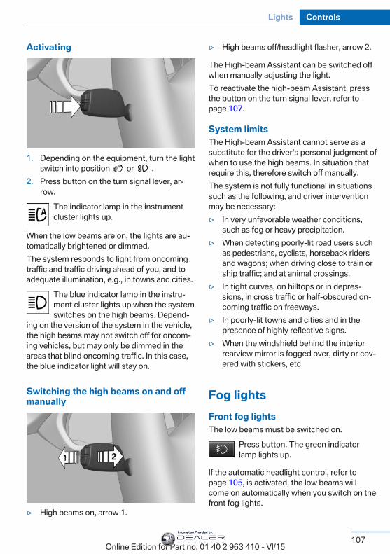
Activating
1. Depending on the equipment, turn the lightswitch into position or .
2. Press button on the turn signal lever, ar‐row.
The indicator lamp in the instrumentcluster lights up.
When the low beams are on, the lights are au‐tomatically brightened or dimmed.The system responds to light from oncomingtraffic and traffic driving ahead of you, and toadequate illumination, e.g., in towns and cities.
The blue indicator lamp in the instru‐ment cluster lights up when the systemswitches on the high beams. Depend‐
ing on the version of the system in the vehicle,the high beams may not switch off for oncom‐ing vehicles, but may only be dimmed in theareas that blind oncoming traffic. In this case,the blue indicator light will stay on.
Switching the high beams on and offmanually
▷ High beams on, arrow 1.
▷ High beams off/headlight flasher, arrow 2.
The High-beam Assistant can be switched offwhen manually adjusting the light.To reactivate the high-beam Assistant, pressthe button on the turn signal lever, refer topage 107.
System limitsThe High-beam Assistant cannot serve as asubstitute for the driver's personal judgment ofwhen to use the high beams. In situation thatrequire this, therefore switch off manually.The system is not fully functional in situationssuch as the following, and driver interventionmay be necessary:▷ In very unfavorable weather conditions,
such as fog or heavy precipitation.▷ When detecting poorly-lit road users such
as pedestrians, cyclists, horseback ridersand wagons; when driving close to train orship traffic; and at animal crossings.
▷ In tight curves, on hilltops or in depres‐sions, in cross traffic or half-obscured on‐coming traffic on freeways.
▷ In poorly-lit towns and cities and in thepresence of highly reflective signs.
▷ When the windshield behind the interiorrearview mirror is fogged over, dirty or cov‐ered with stickers, etc.
Fog lightsFront fog lightsThe low beams must be switched on.
Press button. The green indicatorlamp lights up.
If the automatic headlight control, refer topage 105, is activated, the low beams willcome on automatically when you switch on thefront fog lights.
Seite 107
Lights Controls
107Online Edition for Part no. 01 40 2 963 410 - VI/15
Information Provided by:
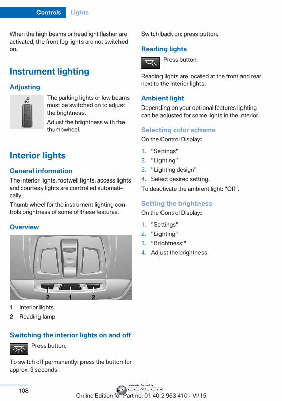
When the high beams or headlight flasher areactivated, the front fog lights are not switchedon.
Instrument lightingAdjusting
The parking lights or low beamsmust be switched on to adjustthe brightness.Adjust the brightness with thethumbwheel.
Interior lightsGeneral informationThe interior lights, footwell lights, access lightsand courtesy lights are controlled automati‐cally.Thumb wheel for the instrument lighting con‐trols brightness of some of these features.
Overview
1 Interior lights2 Reading lamp
Switching the interior lights on and offPress button.
To switch off permanently: press the button forapprox. 3 seconds.
Switch back on: press button.
Reading lightsPress button.
Reading lights are located at the front and rearnext to the interior lights.
Ambient lightDepending on your optional features lightingcan be adjusted for some lights in the interior.
Selecting color schemeOn the Control Display:
1. "Settings"2. "Lighting"3. "Lighting design"4. Select desired setting.To deactivate the ambient light: "Off".
Setting the brightnessOn the Control Display:
1. "Settings"2. "Lighting"3. "Brightness:"4. Adjust the brightness.
Seite 108
Controls Lights
108Online Edition for Part no. 01 40 2 963 410 - VI/15
Information Provided by:
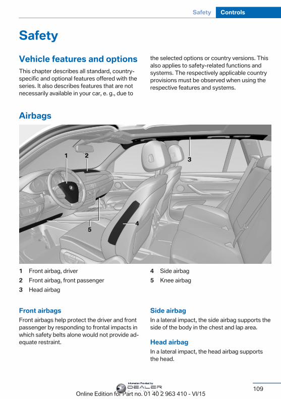
SafetyVehicle features and optionsThis chapter describes all standard, country-specific and optional features offered with theseries. It also describes features that are notnecessarily available in your car, e. g., due to
the selected options or country versions. Thisalso applies to safety-related functions andsystems. The respectively applicable countryprovisions must be observed when using therespective features and systems.
Airbags
1 Front airbag, driver2 Front airbag, front passenger3 Head airbag
4 Side airbag5 Knee airbag
Front airbagsFront airbags help protect the driver and frontpassenger by responding to frontal impacts inwhich safety belts alone would not provide ad‐equate restraint.
Side airbagIn a lateral impact, the side airbag supports theside of the body in the chest and lap area.
Head airbagIn a lateral impact, the head airbag supportsthe head.
Seite 109
Safety Controls
109Online Edition for Part no. 01 40 2 963 410 - VI/15
Information Provided by:
Ejection MitigationThe head airbag system is designed as anejection mitigation countermeasure to reducethe likelihood of ejections of vehicle occupantsthrough side windows during rollovers or sideimpact events.
Knee airbagThe knee airbag supports the legs in a frontalimpact.
Protective actionAirbags are not triggered in every impact situa‐tion, e.g., in less severe accidents or rear-endcollisions.
Information for optimum effect of theairbags
WARNINGIf the seat position is incorrect or the de‐
ployment area of the airbags is impacted, theairbag system cannot protect as intended orcause additional injuries due to triggering.There is risk of injuries or danger to life. Ob‐serve the Information for optimum protectiveeffect of the airbag system.◀
▷ Keep at a distance from the airbags.▷ Make sure that occupants keep their heads
away from the side airbag.▷ Always grasp the steering wheel on the
steering wheel rim. Hold your hands at the3 o'clock and 9 o'clock positions, to keepthe risk of injury to your hands or arms aslow as possible when the airbag is trig‐gered.
▷ Make sure that the front passenger is sit‐ting correctly, i.e., keeps his or her feet andlegs in the floor area.
▷ There should be no persons, animals orobjects between an airbag and a person.
▷ Do not apply adhesive materials to the air‐bag cover panels, do not cover them ormodify them in any way.
▷ Dashboard and windshield on the frontpassenger side must stay clear - do not at‐tach adhesive labels or coverings and donot attach brackets or cables, e. g., for GPSdevices or' mobile phones.
▷ Do not use the cover of the front airbag onthe front passenger side as a storage area.
▷ Do not place slip covers, seat cushions orother objects on the front passenger seatthat are not specifically suited for seatswith integrated side airbags.
▷ Do not hang pieces of clothing, such asjackets, over the backrests.
▷ Never modify either the individual compo‐nents or the wiring in the airbag system.This also applies to steering wheel covers,the dashboard, and the seats.
▷ Do not remove the airbag system.Even when you follow all instructions veryclosely, injury from contact with the airbagscannot be ruled out in certain situations.The ignition and inflation noise may lead toshort-term and, in most cases, temporaryhearing impairment in sensitive individuals.Warnings and information on the airbags arealso found on the sun visors.
Functional readiness of the airbagsystem
InformationWARNINGIndividual components can be hot after
triggering of the airbag system. There is risk ofinjuries. Do not touch individual components.◀
WARNINGImproperly executed work can lead to
failure, malfunction or unintentional triggeringof the airbag system. In the case of a malfunc‐tion, the airbag system could not trigger as in‐tended in the event of an accident despite re‐spective accident severity. There is risk of
Seite 110
Controls Safety
110Online Edition for Part no. 01 40 2 963 410 - VI/15
Information Provided by:
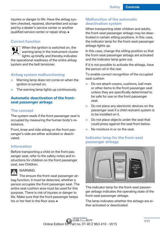
injuries or danger to life. Have the airbag sys‐tem checked, repaired, dismantled and scrap‐ped by a dealer’s service center or anotherqualified service center or repair shop.◀
Correct functionWhen the ignition is switched on, thewarning lamp in the instrument clusterlights up briefly and thereby indicates
the operational readiness of the entire airbagsystem and the belt tensioner.
Airbag system malfunctioning▷ Warning lamp does not come on when the
ignition is turned on.▷ The warning lamp lights up continuously.
Automatic deactivation of the front-seat passenger airbags
The conceptThe system reads if the front passenger seat isoccupied by measuring the human body's re‐sistance.Front, knee and side airbag on the front pas‐senger's side are either activated or deacti‐vated.
InformationBefore transporting a child on the front pas‐senger seat, refer to the safety notes and in‐structions for children on the front passengerseat, see Children.
WARNINGThe ensure the front-seat passenger air‐
bag function, it must be detected, whether aperson occupies the front passenger seat. Theentire seat cushion area must be used for thispurpose. There is risk of injuries or danger tolife. Make sure that the front passenger keepshis or her feet in the floor area.◀
Malfunction of the automaticdeactivation systemWhen transporting older children and adults,the front-seat passenger airbags may be deac‐tivated in certain sitting positions. In this case,the indicator lamp for the front-seat passengerairbags lights up.In this case, change the sitting position so thatthe front-seat passenger airbags are activatedand the indicator lamp goes out.If it is not possible to activate the airbags, havethe person sit in the rear.To enable correct recognition of the occupiedseat cushion▷ Do not attach covers, cushions, ball mats
or other items to the front passenger seatunless they are specifically determined tobe safe for use on the front passengerseat.
▷ Do not place any electronic devices on thepassenger seat if a child restraint system isto be installed on it.
▷ Do not place objects under the seat thatcould press against the seat from below.
▷ No moisture in or on the seat.
Indicator lamp for the front-seatpassenger airbags
The indicator lamp for the front-seat passen‐ger airbags indicates the operating state of thefront-seat passenger airbags.The lamp indicates whether the airbags are ei‐ther activated or deactivated.
Seite 111
Safety Controls
111Online Edition for Part no. 01 40 2 963 410 - VI/15
Information Provided by:
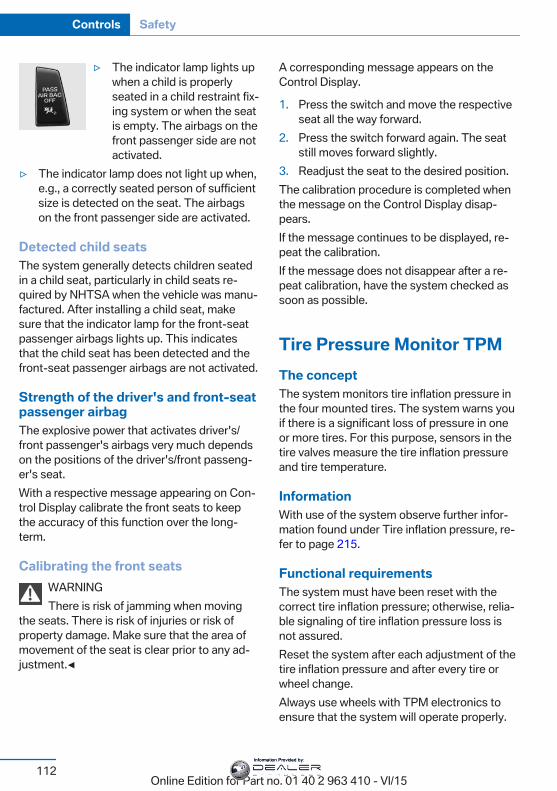
▷ The indicator lamp lights upwhen a child is properlyseated in a child restraint fix‐ing system or when the seatis empty. The airbags on thefront passenger side are notactivated.
▷ The indicator lamp does not light up when,e.g., a correctly seated person of sufficientsize is detected on the seat. The airbagson the front passenger side are activated.
Detected child seatsThe system generally detects children seatedin a child seat, particularly in child seats re‐quired by NHTSA when the vehicle was manu‐factured. After installing a child seat, makesure that the indicator lamp for the front-seatpassenger airbags lights up. This indicatesthat the child seat has been detected and thefront-seat passenger airbags are not activated.
Strength of the driver's and front-seatpassenger airbagThe explosive power that activates driver's/front passenger's airbags very much dependson the positions of the driver's/front passeng‐er's seat.With a respective message appearing on Con‐trol Display calibrate the front seats to keepthe accuracy of this function over the long-term.
Calibrating the front seatsWARNINGThere is risk of jamming when moving
the seats. There is risk of injuries or risk ofproperty damage. Make sure that the area ofmovement of the seat is clear prior to any ad‐justment.◀
A corresponding message appears on theControl Display.
1. Press the switch and move the respectiveseat all the way forward.
2. Press the switch forward again. The seatstill moves forward slightly.
3. Readjust the seat to the desired position.The calibration procedure is completed whenthe message on the Control Display disap‐pears.If the message continues to be displayed, re‐peat the calibration.If the message does not disappear after a re‐peat calibration, have the system checked assoon as possible.
Tire Pressure Monitor TPMThe conceptThe system monitors tire inflation pressure inthe four mounted tires. The system warns youif there is a significant loss of pressure in oneor more tires. For this purpose, sensors in thetire valves measure the tire inflation pressureand tire temperature.
InformationWith use of the system observe further infor‐mation found under Tire inflation pressure, re‐fer to page 215.
Functional requirementsThe system must have been reset with thecorrect tire inflation pressure; otherwise, relia‐ble signaling of tire inflation pressure loss isnot assured.Reset the system after each adjustment of thetire inflation pressure and after every tire orwheel change.Always use wheels with TPM electronics toensure that the system will operate properly.
Seite 112
Controls Safety
112Online Edition for Part no. 01 40 2 963 410 - VI/15
Information Provided by:
Status displayThe current status of the Tire Pressure Moni‐tor TPM can be displayed on the Control Dis‐play, e.g., whether or not the TPM is active.On the Control Display:
1. "Vehicle info"2. "Vehicle status"3. "Tire Pressure Monitor (TPM)"The status is displayed.
Status control displayTire and system status are indicated by thecolor of the wheels and a text message on theControl Display.
All wheels greenSystem is active and will issue a warning rela‐tive to the tire inflation pressures stored duringthe last reset.
One wheel is yellowA flat tire or major drop in inflation pressure inthe indicated tire.
All wheels are yellowA flat tire or major drop in inflation pressure inseveral tires.
Wheels, grayThe system cannot detect a flat tire. Reasonsfor this may be:▷ The system is being reset.▷ Malfunction.
Status informationThe status control display additionally showsthe current tire inflation pressures and, de‐pending on the model, tire temperatures. Itshows the actual values read; they may varydepending on driving style or weather condi‐tions.
Carry out resetReset the system after each adjustment of thetire inflation pressure and after every tire orwheel change.On the Control Display and on the vehicle:
1. "Vehicle info"2. "Vehicle status"3. "Perform reset"4. Start the engine - do not drive off.5. Reset tire inflation pressure: "Perform
reset".6. Drive away.The wheels are displayed in gray and the sta‐tus is displayed.After driving faster than 19 mph/30 km/h for ashort period, the set tire inflation pressures areaccepted as reference values. The reset iscompleted automatically while driving.The progress of the reset is displayed.After a successfully completed Reset, thewheels on the Control Display are shown ingreen and "Tire Pressure Monitor (TPM)active" is displayed.You may interrupt this trip at any time. Whenyou continue the reset resumes automatically.
Low tire pressure messageThe yellow warning lamp lights up. ACheck Control message is displayed.▷ There is a flat tire or a major loss in
tire inflation pressure.▷ No reset was performed for the system.
The system therefore issues a warningbased on the tire inflation pressures beforethe last reset.
1. Reduce your speed and stop cautiously.Avoid sudden braking and steering maneu‐vers.
2. Check whether the vehicle is fitted withnormal tires or run-flat tires.
Seite 113
Safety Controls
113Online Edition for Part no. 01 40 2 963 410 - VI/15
Information Provided by:
Run-flat tires, refer to page 225, are la‐beled with a circular symbol containing theletters RSC marked on the tire's sidewall.
WARNINGA damaged regular tire with low or miss‐
ing tire inflation pressure impacts handling,such as steering and braking response. Run-flat tires can maintain limited stability. There isrisk of an accident. Do not continue driving ifthe vehicle is not equipped with run-flat tires.Observe the information on run-flat tires andcontinued driving with these tires.◀
A low tire inflation pressure might turn on DSCDynamic Stability Control.
Actions in the event of a flat tire
Normal tires1. Identify the damaged tire.
Do this by checking the air pressure in allfour tires.The tire pressure gage of the Mobility Sys‐tem, refer to page 225, can possibly beused for this purpose.If the tire inflation pressure in all four tiresis shown to be correct, it is possible thatthe Tire Pressure Monitor did not performa reset. Then perform the reset.If identification of flat tire damage is notpossible, please contact a dealer’s servicecenter or another qualified service centeror repair shop.
2. Replace the damaged tire with the emer‐gency wheel as needed or fix it where ap‐plicable with the Mobility System.
Use of tire sealant, e.g., the Mobility System,may damage the TPM wheel electronics. Inthis case, have the electronics checked at thenext opportunity and have them replaced ifneeded.
Run-flat tires
Maximum speedYou may continue driving with a damaged tireat speeds up to 50 mph/80 km/h.
Continued driving with a flat tireIf continuing to drive with a damaged tire:
1. Avoid sudden braking and steering maneu‐vers.
2. Do not exceed a speed of 50 mph/80 km/h.3. Check the air pressure in all four tires at
the next opportunity.If the tire inflation pressure in all four tiresis shown to be correct, it is possible thatthe Tire Pressure Monitor did not performa reset. In that case, carry out a reset.
Possible driving distance with complete loss oftire inflation pressure:The possible driving distance after a loss of tireinflation pressure depends on cargo load, driv‐ing style and road conditions.A vehicle with an average load has a possibledriving range of approx. 50 miles/80 km.A vehicle with a damaged tire reacts differ‐ently, e.g., it has reduced lane stability duringbraking, a longer braking distance and differentself-steering properties. Adjust your drivingstyle accordingly. Avoid abrupt steering ma‐neuvers or driving over obstacles, e.g., curbs,potholes, etc.Because the possible driving distance de‐pends on how the vehicle is used during thetrip, the actual distance may be shorter or lon‐ger depending on the driving speed, road con‐ditions, external temperature, cargo load, etc.
WARNINGYour vehicle handles differently when a
run-flat tire is damaged and has low or missingtire inflation pressure, e.g., your lane stability isreduced when braking, braking distances are
Seite 114
Controls Safety
114Online Edition for Part no. 01 40 2 963 410 - VI/15
Information Provided by:
longer and the self-steering properties willchange. There is risk of an accident.Drive moderately and do not exceed a speed of50 mph/80 km/h.◀
Final tire failureVibrations or loud noises while driving can indi‐cate the final failure of a tire.Reduce speed and stop; otherwise, pieces ofthe tire could come loose and cause an acci‐dent.Do not continue driving. Contact a dealer’sservice center or another qualified service cen‐ter or repair shop.
Required tire inflation pressure checkmessageA Check Control message is displayed in thefollowing situations▷ The system has detected a wheel change,
but no reset was done.▷ Inflation was not carried out according to
specifications.▷ The tire inflation pressure has fallen below
the level of the last confirmation.In this case:▷ Check the tire pressure and correct as
needed.▷ Carry out a reset of the system after a tire
change.
System limitsThe system does not function properly if a re‐set has not been carried out, e.g., a flat tire isreported though tire inflation pressures arecorrect.The tire inflation pressure depends on thetire's temperature. Driving or exposure to thesun will increase the tire's temperature, thusincreasing the tire inflation pressure. The tireinflation pressure is reduced when the tiretemperature falls again. These circumstances
may cause a warning when temperatures fallvery sharply.The system cannot indicate sudden serioustire damage caused by external circumstances.
MalfunctionThe yellow warning lamp flashes andthen lights up continuously. A CheckControl message is displayed. No flat
tire or loss of tire inflation pressure can be de‐tected.
Examples and recommendations in the follow‐ing situations:▷ A wheel without TPM electronics is
mounted: Have it checked by a dealer’sservice center or another qualified servicecenter or repair shop as needed.
▷ Malfunction: Have system checked by adealer’s service center or another qualifiedservice center or repair shop.
▷ TPM was unable to complete the reset.Reset the system again.
▷ Interference through systems or deviceswith the same radio frequency: After leav‐ing the area of the interference, the systemautomatically becomes active again.
Declaration according to NHTSA/FMVSS 138 Tire Pressure MonitoringSystemEach tire, including the spare (if provided)should be checked monthly when cold and in‐flated to the inflation pressure recommendedby the vehicle manufacturer on the vehicleplacard or tire inflation pressure label. (If yourvehicle has tires of a different size than the sizeindicated on the vehicle placard or tire inflationpressure label, you should determine theproper tire inflation pressure for those tires.)As an added safety feature, your vehicle hasbeen equipped with a tire pressure monitoringsystem (TPMS) that illuminates a low tire pres‐sure telltale when one or more of your tires issignificantly under-inflated. Accordingly, when
Seite 115
Safety Controls
115Online Edition for Part no. 01 40 2 963 410 - VI/15
Information Provided by:
the low tire pressure telltale illuminates, youshould stop and check your tires as soon aspossible, and inflate them to the proper pres‐sure. Driving on a significantly under-inflatedtire causes the tire to overheat and can lead totire failure. Under-inflation also reduces fuel ef‐ficiency and tire tread life, and may affect thevehicle's handling and stopping ability. Pleasenote that the TPMS is not a substitute forproper tire maintenance, and it is the driver'sresponsibility to maintain correct tire pressure,even if under-inflation has not reached thelevel to trigger illumination of the TPMS lowtire pressure telltale. Your vehicle has alsobeen equipped with a TPMS malfunction indi‐cator to indicate when the system is not oper‐ating properly. The TPMS malfunction indica‐tor is combined with the low tire pressuretelltale. When the system detects a malfunc‐tion, the telltale will flash for approximately oneminute and then remain continuously illumi‐nated. This sequence will continue upon sub‐sequent vehicle start-ups as long as the mal‐function exists. When the malfunction indicatoris illuminated, the system may not be able todetect or signal low tire pressure as intended.TPMS malfunctions may occur for a variety ofreasons, including the installation of replace‐ment or alternate tires or wheels on the vehiclethat prevent the TPMS from functioning prop‐erly. Always check the TPMS malfunction tell‐tale after replacing one or more tires or wheelson your vehicle to ensure that the replacementor alternate tires and wheels allow the TPMSto continue to function properly.
FTM Flat Tire MonitorThe conceptThe system detects tire inflation pressure losson the basis of rotation speed differences be‐tween the individual wheels while driving.In the event of a tire inflation pressure loss, thediameter and therefore the rotational speed of
the corresponding wheel changes. This will bedetected and reported as a flat tire.The system does not measure the actual infla‐tion pressure in the tires.
Functional requirementsThe system must have been initialized whenthe tire inflation pressure was correct; other‐wise, reliable flagging of a flat tire is not as‐sured. Initialize the system after each correc‐tion of the tire inflation pressure and afterevery tire or wheel change.
Status displayThe current status of the Flat Tire Monitor canbe displayed on the Control Display, e.g.,whether or not the FTM is active.On the Control Display:
1. "Vehicle info"2. "Vehicle status"3. "Flat Tire Monitor (FTM)"The status is displayed.
InitializationWhen initializing the once set inflation tirepressures serve as reference values in order todetect a flat tire. Initialization is started by con‐firming the tire inflation pressures.Do not initialize the system when driving withsnow chains.On the Control Display:
1. "Vehicle info"2. "Vehicle status"3. "Perform reset"4. Start the engine - do not drive off.5. Start the initialization with "Perform reset".6. Drive away.The initialization is completed while driving,which can be interrupted at any time.The initialization automatically continues whendriving resumes.
Seite 116
Controls Safety
116Online Edition for Part no. 01 40 2 963 410 - VI/15
Information Provided by:
Indication of a flat tireThe yellow warning lamp lights up. ACheck Control message is displayed.There is a flat tire or a major loss in tire
inflation pressure.
1. Reduce your speed and stop cautiously.Avoid sudden braking and steering maneu‐vers.
2. Check whether the vehicle is fitted withnormal tires or run-flat tires.Run-flat tires, refer to page 225, are la‐beled with a circular symbol containing theletters RSC marked on the tire's sidewall.
WARNINGA damaged regular tire with low or miss‐
ing tire inflation pressure impacts handling,such as steering and braking response. Run-flat tires can maintain limited stability. There isrisk of an accident. Do not continue driving ifthe vehicle is not equipped with run-flat tires.Observe the information on run-flat tires andcontinued driving with these tires.◀
When a flat tire is indicated, DSC Dynamic Sta‐bility Control is switched on if needed.
System limitsA natural, even tire inflation pressure loss in allfour tires will not be recognized. Therefore,check the tire inflation pressure regularly.Sudden serious tire damage caused by exter‐nal circumstances cannot be recognized in ad‐vance.The system could be delayed or malfunction inthe following situations:▷ When the system has not been initialized.▷ When driving on a snowy or slippery road
surface.▷ Sporty driving style: spinning traction
wheels, high lateral acceleration (drifting).▷ When driving with snow chains.
Actions in the event of a flat tire
Normal tires1. Identify the damaged tire.
Do this by checking the air pressure in allfour tires.The tire pressure gage of the Mobility Sys‐tem, refer to page 225, can possibly beused for this purpose.If the tire inflation pressure in all four tiresis correct, the Flat Tire Monitor may nothave been initialized. In this case, initializethe system.If identification of flat tire damage is notpossible, please contact a dealer’s servicecenter or another qualified service centeror repair shop.
2. Replace the damaged tire with the emer‐gency wheel as needed or fix it where ap‐plicable with the Mobility System.
Run-flat tires
Maximum speedYou may continue driving with a damaged tireat speeds up to 50 mph/80 km/h.
Continued driving with a flat tireIf continuing to drive with a damaged tire:
1. Avoid sudden braking and steering maneu‐vers.
2. Do not exceed a speed of 50 mph/80 km/h.3. Check the air pressure in all four tires at
the next opportunity.If the tire inflation pressure in all four tiresis correct, the Flat Tire Monitor may nothave been initialized. In this case, initializethe system.
Possible driving distance with complete loss oftire inflation pressure:
Seite 117
Safety Controls
117Online Edition for Part no. 01 40 2 963 410 - VI/15
Information Provided by:
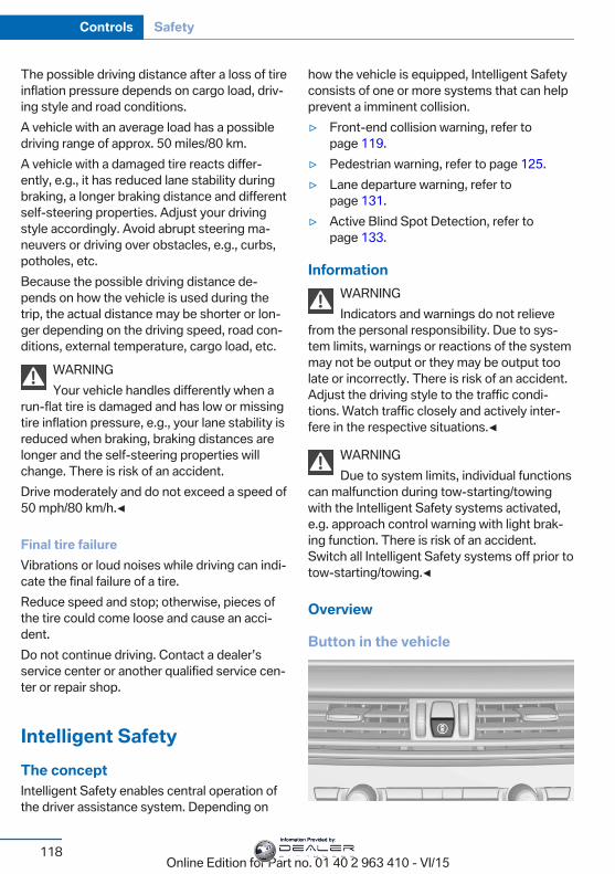
The possible driving distance after a loss of tireinflation pressure depends on cargo load, driv‐ing style and road conditions.A vehicle with an average load has a possibledriving range of approx. 50 miles/80 km.A vehicle with a damaged tire reacts differ‐ently, e.g., it has reduced lane stability duringbraking, a longer braking distance and differentself-steering properties. Adjust your drivingstyle accordingly. Avoid abrupt steering ma‐neuvers or driving over obstacles, e.g., curbs,potholes, etc.Because the possible driving distance de‐pends on how the vehicle is used during thetrip, the actual distance may be shorter or lon‐ger depending on the driving speed, road con‐ditions, external temperature, cargo load, etc.
WARNINGYour vehicle handles differently when a
run-flat tire is damaged and has low or missingtire inflation pressure, e.g., your lane stability isreduced when braking, braking distances arelonger and the self-steering properties willchange. There is risk of an accident.Drive moderately and do not exceed a speed of50 mph/80 km/h.◀
Final tire failureVibrations or loud noises while driving can indi‐cate the final failure of a tire.Reduce speed and stop; otherwise, pieces ofthe tire could come loose and cause an acci‐dent.Do not continue driving. Contact a dealer’sservice center or another qualified service cen‐ter or repair shop.
Intelligent SafetyThe conceptIntelligent Safety enables central operation ofthe driver assistance system. Depending on
how the vehicle is equipped, Intelligent Safetyconsists of one or more systems that can helpprevent a imminent collision.▷ Front-end collision warning, refer to
page 119.▷ Pedestrian warning, refer to page 125.▷ Lane departure warning, refer to
page 131.▷ Active Blind Spot Detection, refer to
page 133.
InformationWARNINGIndicators and warnings do not relieve
from the personal responsibility. Due to sys‐tem limits, warnings or reactions of the systemmay not be output or they may be output toolate or incorrectly. There is risk of an accident.Adjust the driving style to the traffic condi‐tions. Watch traffic closely and actively inter‐fere in the respective situations.◀
WARNINGDue to system limits, individual functions
can malfunction during tow-starting/towingwith the Intelligent Safety systems activated,e.g. approach control warning with light brak‐ing function. There is risk of an accident.Switch all Intelligent Safety systems off prior totow-starting/towing.◀
Overview
Button in the vehicle
Seite 118
Controls Safety
118Online Edition for Part no. 01 40 2 963 410 - VI/15
Information Provided by:
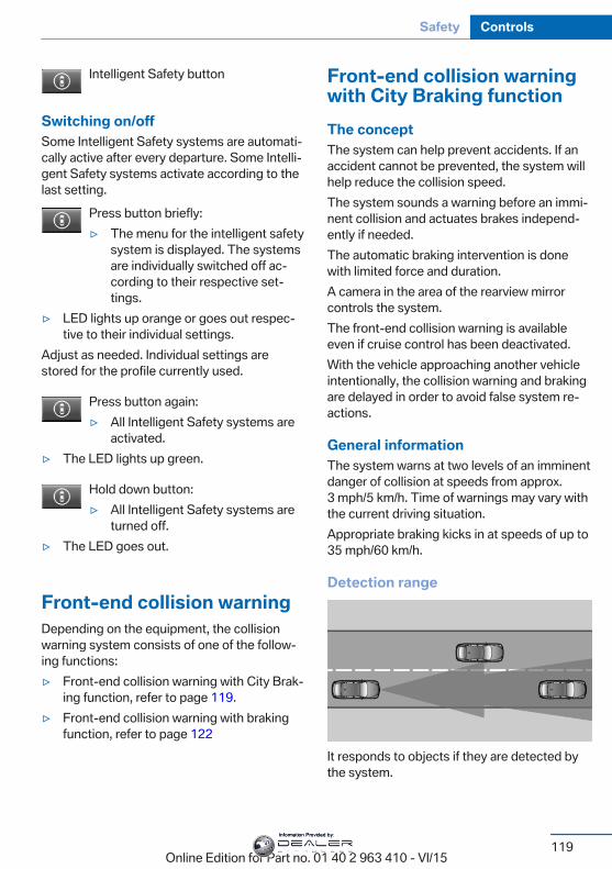
Intelligent Safety button
Switching on/offSome Intelligent Safety systems are automati‐cally active after every departure. Some Intelli‐gent Safety systems activate according to thelast setting.
Press button briefly:▷ The menu for the intelligent safety
system is displayed. The systemsare individually switched off ac‐cording to their respective set‐tings.
▷ LED lights up orange or goes out respec‐tive to their individual settings.
Adjust as needed. Individual settings arestored for the profile currently used.
Press button again:▷ All Intelligent Safety systems are
activated.▷ The LED lights up green.
Hold down button:▷ All Intelligent Safety systems are
turned off.▷ The LED goes out.
Front-end collision warningDepending on the equipment, the collisionwarning system consists of one of the follow‐ing functions:▷ Front-end collision warning with City Brak‐
ing function, refer to page 119.▷ Front-end collision warning with braking
function, refer to page 122
Front-end collision warningwith City Braking functionThe conceptThe system can help prevent accidents. If anaccident cannot be prevented, the system willhelp reduce the collision speed.The system sounds a warning before an immi‐nent collision and actuates brakes independ‐ently if needed.The automatic braking intervention is donewith limited force and duration.A camera in the area of the rearview mirrorcontrols the system.The front-end collision warning is availableeven if cruise control has been deactivated.With the vehicle approaching another vehicleintentionally, the collision warning and brakingare delayed in order to avoid false system re‐actions.
General informationThe system warns at two levels of an imminentdanger of collision at speeds from approx.3 mph/5 km/h. Time of warnings may vary withthe current driving situation.Appropriate braking kicks in at speeds of up to35 mph/60 km/h.
Detection range
It responds to objects if they are detected bythe system.
Seite 119
Safety Controls
119Online Edition for Part no. 01 40 2 963 410 - VI/15
Information Provided by:
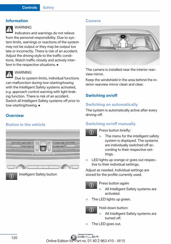
InformationWARNINGIndicators and warnings do not relieve
from the personal responsibility. Due to sys‐tem limits, warnings or reactions of the systemmay not be output or they may be output toolate or incorrectly. There is risk of an accident.Adjust the driving style to the traffic condi‐tions. Watch traffic closely and actively inter‐fere in the respective situations.◀
WARNINGDue to system limits, individual functions
can malfunction during tow-starting/towingwith the Intelligent Safety systems activated,e.g. approach control warning with light brak‐ing function. There is risk of an accident.Switch all Intelligent Safety systems off prior totow-starting/towing.◀
Overview
Button in the vehicle
Intelligent Safety button
Camera
The camera is installed near the interior rear‐view mirror.Keep the windshield in the area behind the in‐terior rearview mirror clean and clear.
Switching on/off
Switching on automaticallyThe system is automatically active after everydriving-off.
Switching on/off manuallyPress button briefly:▷ The menu for the intelligent safety
system is displayed. The systemsare individually switched off ac‐cording to their respective set‐tings.
▷ LED lights up orange or goes out respec‐tive to their individual settings.
Adjust as needed. Individual settings arestored for the profile currently used.
Press button again:▷ All Intelligent Safety systems are
activated.▷ The LED lights up green.
Hold down button:▷ All Intelligent Safety systems are
turned off.▷ The LED goes out.
Seite 120
Controls Safety
120Online Edition for Part no. 01 40 2 963 410 - VI/15
Information Provided by:
Setting the warning timeThe warning time can be set via iDrive.
1. "Settings"2. "Frontal Coll. Warning"3. Activate the desired time on the Control
Display.The selected time is stored for the profile cur‐rently used.
Warning with braking function
DisplayIf a collision with a recognized vehicle is immi‐nent a warning symbol appears in the instru‐ment cluster and in the Head-Up Display.
Symbol Measure
Symbol lights up red: prewarning.Brake and increase distance.
Symbol flashes red and an acousticsignal sounds: acute warning.You are requested to intervene bybraking or make an evasive maneu‐ver.
PrewarningThis warning is issued, e.g., when there is theimpending danger of a collision or the distanceto the vehicle ahead is too small.The driver must intervene actively when thereis a prewarning.
Acute warning with braking functionAcute warning in displayed in case of the immi‐nent danger of a collision when the vehicle ap‐proaches another object at a relatively high dif‐ferential speed.The driver must intervene actively when thereis an acute warning. If necessary, the driver isassisted by a minor automatic braking inter‐vention in a possible risk of collision.
Acute warnings can also be triggered withoutprevious forewarning.
Braking interventionThe warning prompts the driver himself/herselfto react. During a warning, the maximum brak‐ing force is used. Premise for the brake boos‐ter is sufficiently quick and hard stepping onthe brake pedal. The system can assist withsome braking intervention if there is risk of acollision. At low speeds vehicles may thuscome to a complete stop.The braking intervention is executed only ifDSC Dynamic Stability Control is switched onand Dynamic Traction Control DTC is acti‐vated.The braking intervention can be interrupted bystepping on the accelerator pedal or by ac‐tively moving the steering wheel.Object detection can be restricted. Limitationsof the detection range and functional restric‐tions are to be considered.
System limits
Detection rangeThe system's detection potential is limited.Thus a system reaction might not come ormight come late.E. g. the following situations may not be de‐tected:▷ Slow moving vehicles when you approach
them at high speed.▷ Vehicles that suddenly swerve in front of
you, or sharply decelerating vehicles.▷ Vehicles with an unusual rear appearance.▷ Two-wheeled vehicles ahead of you.
Functional limitationsThe system may not be fully functional in thefollowing situations:▷ In heavy fog, rain, sprayed water or snow‐
fall.
Seite 121
Safety Controls
121Online Edition for Part no. 01 40 2 963 410 - VI/15
Information Provided by:
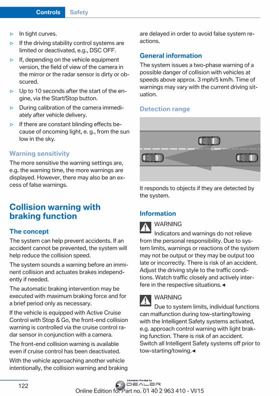
▷ In tight curves.▷ If the driving stability control systems are
limited or deactivated, e.g., DSC OFF.▷ If, depending on the vehicle equipment
version, the field of view of the camera inthe mirror or the radar sensor is dirty or ob‐scured.
▷ Up to 10 seconds after the start of the en‐gine, via the Start/Stop button.
▷ During calibration of the camera immedi‐ately after vehicle delivery.
▷ If there are constant blinding effects be‐cause of oncoming light, e. g., from the sunlow in the sky.
Warning sensitivityThe more sensitive the warning settings are,e.g. the warning time, the more warnings aredisplayed. However, there may also be an ex‐cess of false warnings.
Collision warning withbraking functionThe conceptThe system can help prevent accidents. If anaccident cannot be prevented, the system willhelp reduce the collision speed.The system sounds a warning before an immi‐nent collision and actuates brakes independ‐ently if needed.The automatic braking intervention may beexecuted with maximum braking force and fora brief period only as necessary.If the vehicle is equipped with Active CruiseControl with Stop & Go, the front-end collisionwarning is controlled via the cruise control ra‐dar sensor in conjunction with a camera.The front-end collision warning is availableeven if cruise control has been deactivated.With the vehicle approaching another vehicleintentionally, the collision warning and braking
are delayed in order to avoid false system re‐actions.
General informationThe system issues a two-phase warning of apossible danger of collision with vehicles atspeeds above approx. 3 mph/5 km/h. Time ofwarnings may vary with the current driving sit‐uation.
Detection range
It responds to objects if they are detected bythe system.
InformationWARNINGIndicators and warnings do not relieve
from the personal responsibility. Due to sys‐tem limits, warnings or reactions of the systemmay not be output or they may be output toolate or incorrectly. There is risk of an accident.Adjust the driving style to the traffic condi‐tions. Watch traffic closely and actively inter‐fere in the respective situations.◀
WARNINGDue to system limits, individual functions
can malfunction during tow-starting/towingwith the Intelligent Safety systems activated,e.g. approach control warning with light brak‐ing function. There is risk of an accident.Switch all Intelligent Safety systems off prior totow-starting/towing.◀
Seite 122
Controls Safety
122Online Edition for Part no. 01 40 2 963 410 - VI/15
Information Provided by:
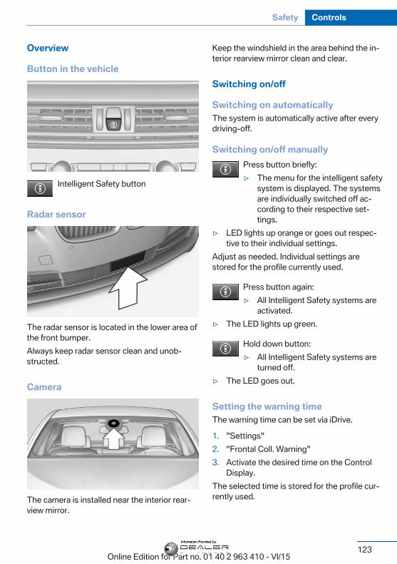
Overview
Button in the vehicle
Intelligent Safety button
Radar sensor
The radar sensor is located in the lower area ofthe front bumper.Always keep radar sensor clean and unob‐structed.
Camera
The camera is installed near the interior rear‐view mirror.
Keep the windshield in the area behind the in‐terior rearview mirror clean and clear.
Switching on/off
Switching on automaticallyThe system is automatically active after everydriving-off.
Switching on/off manuallyPress button briefly:▷ The menu for the intelligent safety
system is displayed. The systemsare individually switched off ac‐cording to their respective set‐tings.
▷ LED lights up orange or goes out respec‐tive to their individual settings.
Adjust as needed. Individual settings arestored for the profile currently used.
Press button again:▷ All Intelligent Safety systems are
activated.▷ The LED lights up green.
Hold down button:▷ All Intelligent Safety systems are
turned off.▷ The LED goes out.
Setting the warning timeThe warning time can be set via iDrive.
1. "Settings"2. "Frontal Coll. Warning"3. Activate the desired time on the Control
Display.The selected time is stored for the profile cur‐rently used.
Seite 123
Safety Controls
123Online Edition for Part no. 01 40 2 963 410 - VI/15
Information Provided by:
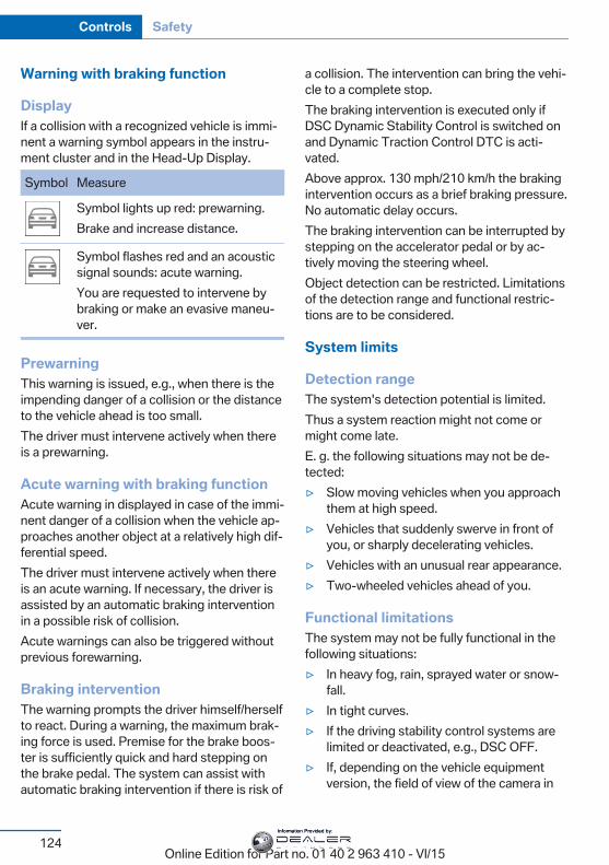
Warning with braking function
DisplayIf a collision with a recognized vehicle is immi‐nent a warning symbol appears in the instru‐ment cluster and in the Head-Up Display.
Symbol Measure
Symbol lights up red: prewarning.Brake and increase distance.
Symbol flashes red and an acousticsignal sounds: acute warning.You are requested to intervene bybraking or make an evasive maneu‐ver.
PrewarningThis warning is issued, e.g., when there is theimpending danger of a collision or the distanceto the vehicle ahead is too small.The driver must intervene actively when thereis a prewarning.
Acute warning with braking functionAcute warning in displayed in case of the immi‐nent danger of a collision when the vehicle ap‐proaches another object at a relatively high dif‐ferential speed.The driver must intervene actively when thereis an acute warning. If necessary, the driver isassisted by an automatic braking interventionin a possible risk of collision.Acute warnings can also be triggered withoutprevious forewarning.
Braking interventionThe warning prompts the driver himself/herselfto react. During a warning, the maximum brak‐ing force is used. Premise for the brake boos‐ter is sufficiently quick and hard stepping onthe brake pedal. The system can assist withautomatic braking intervention if there is risk of
a collision. The intervention can bring the vehi‐cle to a complete stop.The braking intervention is executed only ifDSC Dynamic Stability Control is switched onand Dynamic Traction Control DTC is acti‐vated.Above approx. 130 mph/210 km/h the brakingintervention occurs as a brief braking pressure.No automatic delay occurs.The braking intervention can be interrupted bystepping on the accelerator pedal or by ac‐tively moving the steering wheel.Object detection can be restricted. Limitationsof the detection range and functional restric‐tions are to be considered.
System limits
Detection rangeThe system's detection potential is limited.Thus a system reaction might not come ormight come late.E. g. the following situations may not be de‐tected:▷ Slow moving vehicles when you approach
them at high speed.▷ Vehicles that suddenly swerve in front of
you, or sharply decelerating vehicles.▷ Vehicles with an unusual rear appearance.▷ Two-wheeled vehicles ahead of you.
Functional limitationsThe system may not be fully functional in thefollowing situations:▷ In heavy fog, rain, sprayed water or snow‐
fall.▷ In tight curves.▷ If the driving stability control systems are
limited or deactivated, e.g., DSC OFF.▷ If, depending on the vehicle equipment
version, the field of view of the camera in
Seite 124
Controls Safety
124Online Edition for Part no. 01 40 2 963 410 - VI/15
Information Provided by:
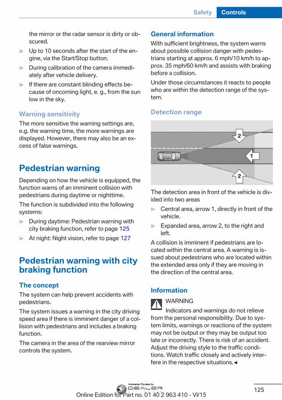
the mirror or the radar sensor is dirty or ob‐scured.
▷ Up to 10 seconds after the start of the en‐gine, via the Start/Stop button.
▷ During calibration of the camera immedi‐ately after vehicle delivery.
▷ If there are constant blinding effects be‐cause of oncoming light, e. g., from the sunlow in the sky.
Warning sensitivityThe more sensitive the warning settings are,e.g. the warning time, the more warnings aredisplayed. However, there may also be an ex‐cess of false warnings.
Pedestrian warningDepending on how the vehicle is equipped, thefunction warns of an imminent collision withpedestrians during daytime or nighttime.The function is subdivided into the followingsystems:▷ During daytime: Pedestrian warning with
city braking function, refer to page 125▷ At night: Night vision, refer to page 127
Pedestrian warning with citybraking functionThe conceptThe system can help prevent accidents withpedestrians.The system issues a warning in the city drivingspeed area if there is imminent danger of a col‐lision with pedestrians and includes a brakingfunction.The camera in the area of the rearview mirrorcontrols the system.
General informationWith sufficient brightness, the system warnsabout possible collision danger with pedes‐trians starting at approx. 6 mph/10 km/h to ap‐prox. 35 mph/60 km/h and assists with brakingbefore a collision.Under those circumstances it reacts to peoplewho are within the detection range of the sys‐tem.
Detection range
The detection area in front of the vehicle is div‐ided into two areas▷ Central area, arrow 1, directly in front of the
vehicle.▷ Expanded area, arrow 2, to the right and
left.A collision is imminent if pedestrians are lo‐cated within the central area. A warning is is‐sued about pedestrians who are located withinthe extended area only if they are moving inthe direction of the central area.
InformationWARNINGIndicators and warnings do not relieve
from the personal responsibility. Due to sys‐tem limits, warnings or reactions of the systemmay not be output or they may be output toolate or incorrectly. There is risk of an accident.Adjust the driving style to the traffic condi‐tions. Watch traffic closely and actively inter‐fere in the respective situations.◀
Seite 125
Safety Controls
125Online Edition for Part no. 01 40 2 963 410 - VI/15
Information Provided by:
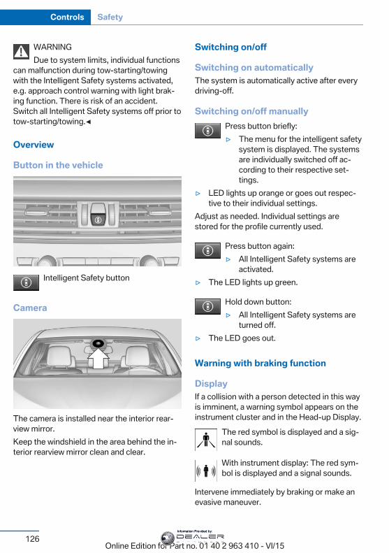
WARNINGDue to system limits, individual functions
can malfunction during tow-starting/towingwith the Intelligent Safety systems activated,e.g. approach control warning with light brak‐ing function. There is risk of an accident.Switch all Intelligent Safety systems off prior totow-starting/towing.◀
Overview
Button in the vehicle
Intelligent Safety button
Camera
The camera is installed near the interior rear‐view mirror.Keep the windshield in the area behind the in‐terior rearview mirror clean and clear.
Switching on/off
Switching on automaticallyThe system is automatically active after everydriving-off.
Switching on/off manuallyPress button briefly:▷ The menu for the intelligent safety
system is displayed. The systemsare individually switched off ac‐cording to their respective set‐tings.
▷ LED lights up orange or goes out respec‐tive to their individual settings.
Adjust as needed. Individual settings arestored for the profile currently used.
Press button again:▷ All Intelligent Safety systems are
activated.▷ The LED lights up green.
Hold down button:▷ All Intelligent Safety systems are
turned off.▷ The LED goes out.
Warning with braking function
DisplayIf a collision with a person detected in this wayis imminent, a warning symbol appears on theinstrument cluster and in the Head-up Display.
The red symbol is displayed and a sig‐nal sounds.
With instrument display: The red sym‐bol is displayed and a signal sounds.
Intervene immediately by braking or make anevasive maneuver.
Seite 126
Controls Safety
126Online Edition for Part no. 01 40 2 963 410 - VI/15
Information Provided by:
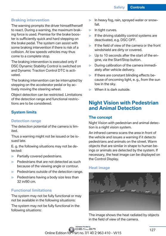
Braking interventionThe warning prompts the driver himself/herselfto react. During a warning, the maximum brak‐ing force is used. Premise for the brake boos‐ter is sufficiently quick and hard stepping onthe brake pedal. The system can assist withsome braking intervention if there is risk of acollision. At low speeds vehicles may thuscome to a complete stop.The braking intervention is executed only ifDSC Dynamic Stability Control is switched onand Dynamic Traction Control DTC is acti‐vated.The braking intervention can be interrupted bystepping on the accelerator pedal or by ac‐tively moving the steering wheel.Object detection can be restricted. Limitationsof the detection range and functional restric‐tions are to be considered.
System limits
Detection rangeThe detection potential of the camera is lim‐ited.Thus a warning might not be issued or be is‐sued late.E. g. the following situations may not be de‐tected:▷ Partially covered pedestrians.▷ Pedestrians that are not detected as such
because of the viewing angle or contour.▷ Pedestrians outside of the detection range.▷ Pedestrians having a body size less than
32 in/80 cm.
Functional limitationsThe system may not be fully functional or maynot be available in the following situations:The system may not be fully functional in thefollowing situations:
▷ In heavy fog, rain, sprayed water or snow‐fall.
▷ In tight curves.▷ If the driving stability control systems are
deactivated, e.g. DSC OFF.▷ If the field of view of the camera or the front
windshield are dirty or covered.▷ Up to 10 seconds after the start of the en‐
gine, via the Start/Stop button.▷ During calibration of the camera immedi‐
ately after vehicle delivery.▷ If there are constant blinding effects be‐
cause of oncoming light, e. g., from the sunlow in the sky.
▷ When it is dark outside.
Night Vision with Pedestrianand Animal DetectionThe conceptNight Vision with pedestrian and animal detec‐tion is a night vision system.An infrared camera scans the area in front ofthe vehicle and issues a warning if it detectspedestrians and animals on the street. Warmobjects that are similar in shape to human be‐ings or animals are detected by the system. Ifnecessary, the heat image can be displayed onthe Control Display.
Heat image
The image shows the heat radiated by objectsin the field of view of the camera.
Seite 127
Safety Controls
127Online Edition for Part no. 01 40 2 963 410 - VI/15
Information Provided by:
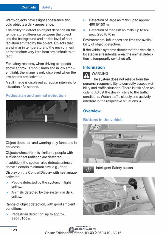
Warm objects have a light appearance andcold objects a dark appearance.The ability to detect an object depends on thetemperature difference between the objectand the background and on the level of heatradiation emitted by the object. Objects thatare similar in temperature to the environmentor that radiate very little heat are difficult to de‐tect.
For safety reasons, when driving at speedsabove approx. 3 mph/5 km/h and in low ambi‐ent light, the image is only displayed when thelow beams are activated.A still image is displayed at regular intervals fora fraction of a second.
Pedestrian and animal detection
Object detection and warning only functions indarkness.Objects whose form is similar to people withsufficient heat radiation are detected.In addition, the system also detects animalsabove a certain minimum size, e.g., deer.Display on the Control Display with heat imageactivated:▷ People detected by the system: in light
yellow.▷ Animals detected by the system: in dark
yellow.
Range of object detection, with good ambientconditions:▷ Pedestrian detection: up to approx.
330 ft/100 m
▷ Detection of large animals: up to approx.490 ft/150 m
▷ Detection of medium animals: up to ap‐prox. 230 ft/70 m
Environmental influences can limit the availa‐bility of object detection.If the vehicle systems detect that the vehicle islocated in a residential area, the animal detec‐tion is temporarily switched off.
InformationWARNINGThe system does not relieve from the
personal responsibility to correctly assess visi‐bility and traffic situation. There is risk of an ac‐cident. Adjust the driving style to the trafficconditions. Watch traffic closely and activelyinterfere in the respective situations.◀
Overview
Buttons in the vehicle
Intelligent Safety button
Seite 128
Controls Safety
128Online Edition for Part no. 01 40 2 963 410 - VI/15
Information Provided by:
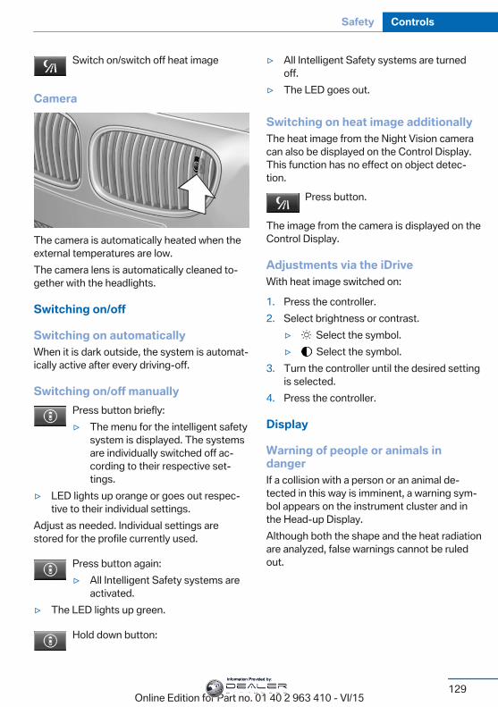
Switch on/switch off heat image
Camera
The camera is automatically heated when theexternal temperatures are low.The camera lens is automatically cleaned to‐gether with the headlights.
Switching on/off
Switching on automaticallyWhen it is dark outside, the system is automat‐ically active after every driving-off.
Switching on/off manuallyPress button briefly:▷ The menu for the intelligent safety
system is displayed. The systemsare individually switched off ac‐cording to their respective set‐tings.
▷ LED lights up orange or goes out respec‐tive to their individual settings.
Adjust as needed. Individual settings arestored for the profile currently used.
Press button again:▷ All Intelligent Safety systems are
activated.▷ The LED lights up green.
Hold down button:
▷ All Intelligent Safety systems are turnedoff.
▷ The LED goes out.
Switching on heat image additionallyThe heat image from the Night Vision cameracan also be displayed on the Control Display.This function has no effect on object detec‐tion.
Press button.
The image from the camera is displayed on theControl Display.
Adjustments via the iDriveWith heat image switched on:
1. Press the controller.2. Select brightness or contrast.
▷ Select the symbol.▷ Select the symbol.
3. Turn the controller until the desired settingis selected.
4. Press the controller.
Display
Warning of people or animals indangerIf a collision with a person or an animal de‐tected in this way is imminent, a warning sym‐bol appears on the instrument cluster and inthe Head-up Display.Although both the shape and the heat radiationare analyzed, false warnings cannot be ruledout.
Seite 129
Safety Controls
129Online Edition for Part no. 01 40 2 963 410 - VI/15
Information Provided by:
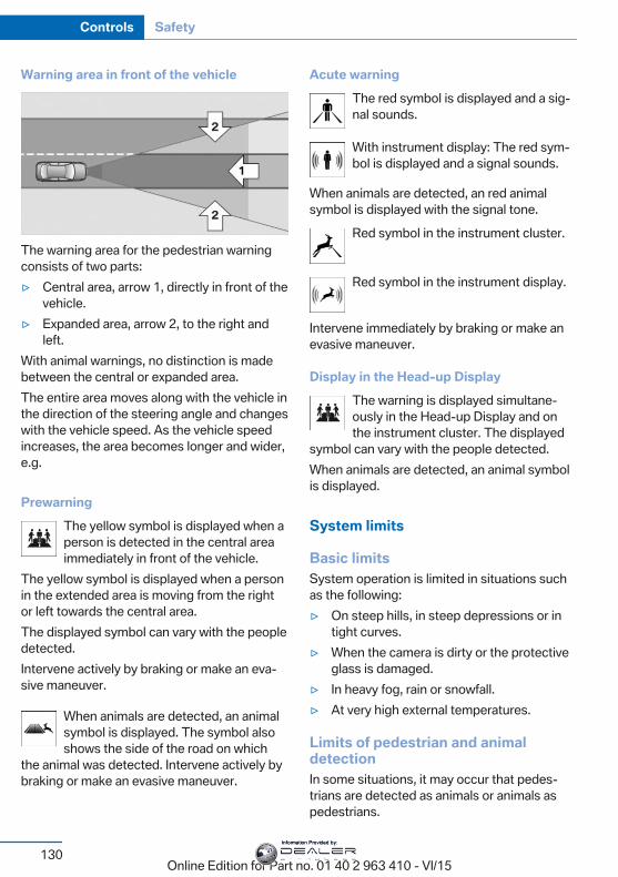
Warning area in front of the vehicle
The warning area for the pedestrian warningconsists of two parts:▷ Central area, arrow 1, directly in front of the
vehicle.▷ Expanded area, arrow 2, to the right and
left.With animal warnings, no distinction is madebetween the central or expanded area.The entire area moves along with the vehicle inthe direction of the steering angle and changeswith the vehicle speed. As the vehicle speedincreases, the area becomes longer and wider,e.g.
PrewarningThe yellow symbol is displayed when aperson is detected in the central areaimmediately in front of the vehicle.
The yellow symbol is displayed when a personin the extended area is moving from the rightor left towards the central area.The displayed symbol can vary with the peopledetected.Intervene actively by braking or make an eva‐sive maneuver.
When animals are detected, an animalsymbol is displayed. The symbol alsoshows the side of the road on which
the animal was detected. Intervene actively bybraking or make an evasive maneuver.
Acute warningThe red symbol is displayed and a sig‐nal sounds.
With instrument display: The red sym‐bol is displayed and a signal sounds.
When animals are detected, an red animalsymbol is displayed with the signal tone.
Red symbol in the instrument cluster.
Red symbol in the instrument display.
Intervene immediately by braking or make anevasive maneuver.
Display in the Head-up DisplayThe warning is displayed simultane‐ously in the Head-up Display and onthe instrument cluster. The displayed
symbol can vary with the people detected.When animals are detected, an animal symbolis displayed.
System limits
Basic limitsSystem operation is limited in situations suchas the following:▷ On steep hills, in steep depressions or in
tight curves.▷ When the camera is dirty or the protective
glass is damaged.▷ In heavy fog, rain or snowfall.▷ At very high external temperatures.
Limits of pedestrian and animaldetectionIn some situations, it may occur that pedes‐trians are detected as animals or animals aspedestrians.
Seite 130
Controls Safety
130Online Edition for Part no. 01 40 2 963 410 - VI/15
Information Provided by:
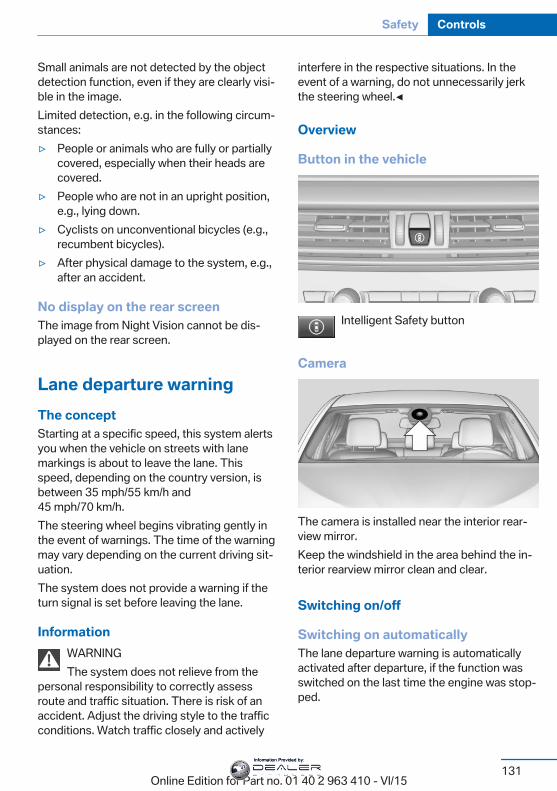
Small animals are not detected by the objectdetection function, even if they are clearly visi‐ble in the image.Limited detection, e.g. in the following circum‐stances:▷ People or animals who are fully or partially
covered, especially when their heads arecovered.
▷ People who are not in an upright position,e.g., lying down.
▷ Cyclists on unconventional bicycles (e.g.,recumbent bicycles).
▷ After physical damage to the system, e.g.,after an accident.
No display on the rear screenThe image from Night Vision cannot be dis‐played on the rear screen.
Lane departure warningThe conceptStarting at a specific speed, this system alertsyou when the vehicle on streets with lanemarkings is about to leave the lane. Thisspeed, depending on the country version, isbetween 35 mph/55 km/h and45 mph/70 km/h.The steering wheel begins vibrating gently inthe event of warnings. The time of the warningmay vary depending on the current driving sit‐uation.The system does not provide a warning if theturn signal is set before leaving the lane.
InformationWARNINGThe system does not relieve from the
personal responsibility to correctly assessroute and traffic situation. There is risk of anaccident. Adjust the driving style to the trafficconditions. Watch traffic closely and actively
interfere in the respective situations. In theevent of a warning, do not unnecessarily jerkthe steering wheel.◀
Overview
Button in the vehicle
Intelligent Safety button
Camera
The camera is installed near the interior rear‐view mirror.Keep the windshield in the area behind the in‐terior rearview mirror clean and clear.
Switching on/off
Switching on automaticallyThe lane departure warning is automaticallyactivated after departure, if the function wasswitched on the last time the engine was stop‐ped.
Seite 131
Safety Controls
131Online Edition for Part no. 01 40 2 963 410 - VI/15
Information Provided by:
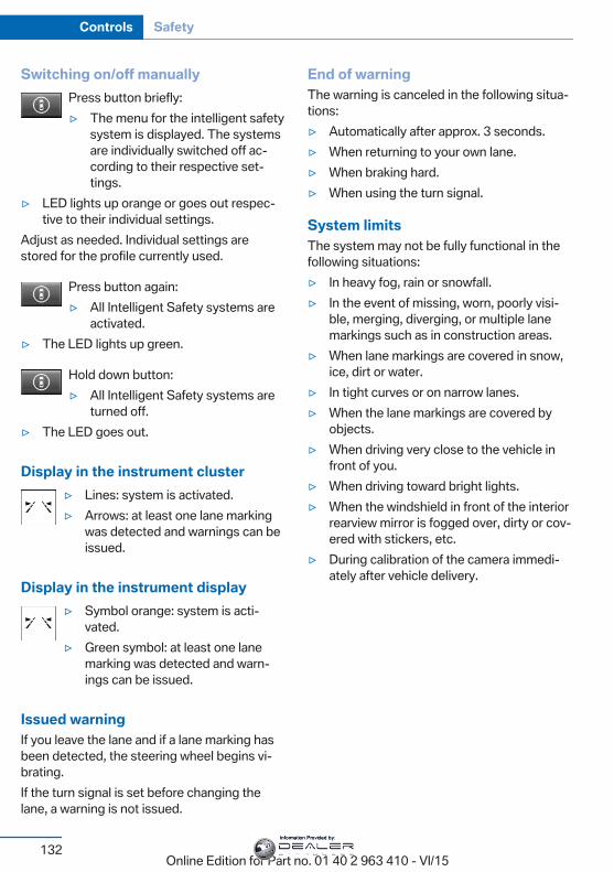
Switching on/off manuallyPress button briefly:▷ The menu for the intelligent safety
system is displayed. The systemsare individually switched off ac‐cording to their respective set‐tings.
▷ LED lights up orange or goes out respec‐tive to their individual settings.
Adjust as needed. Individual settings arestored for the profile currently used.
Press button again:▷ All Intelligent Safety systems are
activated.▷ The LED lights up green.
Hold down button:▷ All Intelligent Safety systems are
turned off.▷ The LED goes out.
Display in the instrument cluster▷ Lines: system is activated.▷ Arrows: at least one lane marking
was detected and warnings can beissued.
Display in the instrument display▷ Symbol orange: system is acti‐
vated.▷ Green symbol: at least one lane
marking was detected and warn‐ings can be issued.
Issued warningIf you leave the lane and if a lane marking hasbeen detected, the steering wheel begins vi‐brating.If the turn signal is set before changing thelane, a warning is not issued.
End of warningThe warning is canceled in the following situa‐tions:▷ Automatically after approx. 3 seconds.▷ When returning to your own lane.▷ When braking hard.▷ When using the turn signal.
System limitsThe system may not be fully functional in thefollowing situations:▷ In heavy fog, rain or snowfall.▷ In the event of missing, worn, poorly visi‐
ble, merging, diverging, or multiple lanemarkings such as in construction areas.
▷ When lane markings are covered in snow,ice, dirt or water.
▷ In tight curves or on narrow lanes.▷ When the lane markings are covered by
objects.▷ When driving very close to the vehicle in
front of you.▷ When driving toward bright lights.▷ When the windshield in front of the interior
rearview mirror is fogged over, dirty or cov‐ered with stickers, etc.
▷ During calibration of the camera immedi‐ately after vehicle delivery.
Seite 132
Controls Safety
132Online Edition for Part no. 01 40 2 963 410 - VI/15
Information Provided by:
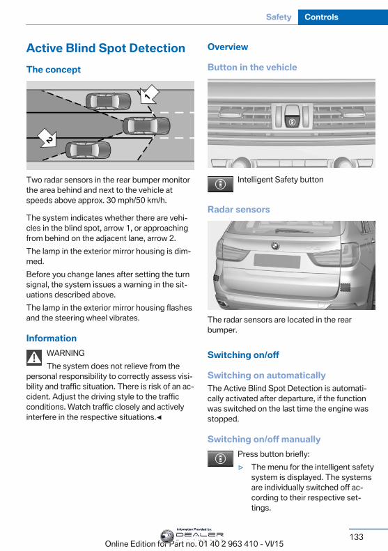
Active Blind Spot DetectionThe concept
Two radar sensors in the rear bumper monitorthe area behind and next to the vehicle atspeeds above approx. 30 mph/50 km/h.
The system indicates whether there are vehi‐cles in the blind spot, arrow 1, or approachingfrom behind on the adjacent lane, arrow 2.The lamp in the exterior mirror housing is dim‐med.Before you change lanes after setting the turnsignal, the system issues a warning in the sit‐uations described above.The lamp in the exterior mirror housing flashesand the steering wheel vibrates.
InformationWARNINGThe system does not relieve from the
personal responsibility to correctly assess visi‐bility and traffic situation. There is risk of an ac‐cident. Adjust the driving style to the trafficconditions. Watch traffic closely and activelyinterfere in the respective situations.◀
Overview
Button in the vehicle
Intelligent Safety button
Radar sensors
The radar sensors are located in the rearbumper.
Switching on/off
Switching on automaticallyThe Active Blind Spot Detection is automati‐cally activated after departure, if the functionwas switched on the last time the engine wasstopped.
Switching on/off manuallyPress button briefly:▷ The menu for the intelligent safety
system is displayed. The systemsare individually switched off ac‐cording to their respective set‐tings.
Seite 133
Safety Controls
133Online Edition for Part no. 01 40 2 963 410 - VI/15
Information Provided by:
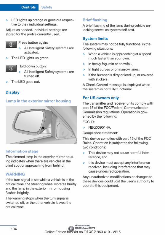
▷ LED lights up orange or goes out respec‐tive to their individual settings.
Adjust as needed. Individual settings arestored for the profile currently used.
Press button again:▷ All Intelligent Safety systems are
activated.▷ The LED lights up green.
Hold down button:▷ All Intelligent Safety systems are
turned off.▷ The LED goes out.
Display
Lamp in the exterior mirror housing
Information stageThe dimmed lamp in the exterior mirror hous‐ing indicates when there are vehicles in theblind spot or approaching from behind.
WARNINGIf the turn signal is set while a vehicle is in thecritical zone, the steering wheel vibrates brieflyand the lamp in the exterior mirror housingflashes brightly.The warning stops when the turn signal isswitched off, or the other vehicle leaves thecritical zone.
Brief flashingA brief flashing of the lamp during vehicle un‐locking serves as system self-test.
System limitsThe system may not be fully functional in thefollowing situations:▷ When a vehicle is approaching at a speed
much faster than your own.▷ In heavy fog, rain or snowfall.▷ In tight curves or on narrow lanes.▷ If the bumper is dirty or iced up, or covered
with stickers.A Check Control message is displayed whenthe system is not fully functional.
For US owners onlyThe transmitter and receiver units comply withpart 15 of the FCC/Federal CommunicationCommission regulations. Operation is gov‐erned by the following:FCC ID:▷ NBG009014A.Compliance statement:This device complies with part 15 of the FCCRules. Operation is subject to the followingtwo conditions:▷ This device may not cause harmful inter‐
ference, and▷ this device must accept any interference
received, including interference that maycause undesired operation.
Any unauthorized modifications or changes tothese devices could void the user's authority tooperate this equipment.
Seite 134
Controls Safety
134Online Edition for Part no. 01 40 2 963 410 - VI/15
Information Provided by:
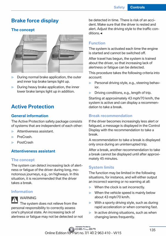
Brake force displayThe concept
▷ During normal brake application, the outerand inner top brake lamps light up.
▷ During heavy brake application, the innerlower brake lamps light up in addition.
Active ProtectionGeneral informationThe Active Protection safety package consistsof systems that are independent of each other:▷ Attentiveness assistant.▷ PreCrash.▷ PostCrash
Attentiveness assistant
The conceptThe system can detect increasing lack of alert‐ness or fatigue of the driver during long, mo‐notonous journeys, e.g., on highways. In thissituation, it is recommended that the drivertakes a break.
InformationWARNINGThe system does not relieve from the
personal responsibility to correctly assessone's physical state. An increasing lack ofalertness or fatigue may not be detected or not
be detected in time. There is risk of an acci‐dent. Make sure that the driver is rested andalert. Adjust the driving style to the traffic con‐ditions.◀
FunctionThe system is activated each time the engineis started and cannot be switched off.After travel has begun, the system is trainedabout the driver, so that increasing lack ofalertness or fatigue can be detected.This procedure takes the following criteria intoaccount:▷ Personal driving style, e.g., steering behav‐
ior.▷ Driving conditions, e.g., length of trip.Starting at approximately 43 mph/70 km/h, thesystem is active and can display a recommen‐dation to take a break.
Break recommendationIf the driver becomes increasingly less alert orfatigued, a message is displayed in the ControlDisplay with the recommendation to take abreak.A recommendation to take a break is displayedonly once during an uninterrupted trip.After a break, another recommendation to takea break cannot be displayed until after approxi‐mately 45 minutes.
System limitsThe function may be limited in the followingsituations, for instance, and will either outputan incorrect warning or no warning at all:▷ When the clock is set incorrectly.▷ When the vehicle speed is mainly below
about 43 mph/70 km/h.▷ With a sporty driving style, such as during
rapid acceleration or when cornering fast.▷ In active driving situations, such as when
changing lanes frequently.
Seite 135
Safety Controls
135Online Edition for Part no. 01 40 2 963 410 - VI/15
Information Provided by:
▷ When the road surface is poor.▷ In the event of strong side winds.
PreCrash
The conceptWith this system critical driving situations thatmight result in an accident can be detectedabove a speed of approx. 20 mph/30 km/h. Inthese situations, preventive measures are au‐tomatically taken to minimize the risk of an ac‐cident as much as possible.Critical driving situations may include:▷ Emergency stop.▷ Severe understeering.▷ Severe oversteering.If the vehicle includes the front-end collisionwarning or front-end collision warning withbraking feature, impending collisions with vehi‐cles driving ahead or stopped in front of youcan also be detected within the system'srange.
InformationWARNINGThe system does not relieve from the
personal responsibility. Due to the system lim‐its, critical situation could not be detected reli‐ably or in time. There is risk of an accident. Ad‐just the driving style to the traffic conditions.Watch traffic closely and actively interfere inthe respective situations.◀
FunctionAfter the safety belt is buckled, the front beltsare automatically pretensioned once after thevehicle is driven is away.In critical driving situations, the following indi‐vidual functions become active as needed:▷ The front belts are automatically preten‐
sioned.▷ Automatic closing of the windows.
▷ Automatic closing of the glass sunroof.▷ For vehicles equipped with Comfort Seats:
automatic positioning of the backrest forthe front passenger seat.
After a critical driving situation without an acci‐dent, the front belts are loosened again. Allother systems can be restored to the desiredsetting.If the belt tension does not loosen automati‐cally, stop the vehicle and unbuckle the beltusing the red button in the buckle. Fasten thebelt before continuing on your trip.
PostCrashIn the event of an accident, the system canbring the car to a halt automatically without in‐tervention by the driver in certain situations.This can reduce the risk of a further collisionand the consequences thereof.Depressing the brake pedal can cause the ve‐hicle to brake harder. This interrupts automaticbraking. Destepping on the gas pedal also in‐terrupts automatic braking.After coming to a halt, the brake is releasedautomatically. Secure the vehicle against roll‐ing.
Seite 136
Controls Safety
136Online Edition for Part no. 01 40 2 963 410 - VI/15
Information Provided by:
Driving stability control systemsVehicle features and optionsThis chapter describes all standard, country-specific and optional features offered with theseries. It also describes features that are notnecessarily available in your car, e. g., due tothe selected options or country versions. Thisalso applies to safety-related functions andsystems. The respectively applicable countryprovisions must be observed when using therespective features and systems.
Anti-lock Braking SystemABSABS prevents locking of the wheels duringbraking.The vehicle contains its steering power evenduring full brake applications, thus increasingactive safety.ABS is operational every time you start the en‐gine.
Brake assistantWhen you apply the brakes rapidly, this systemautomatically produces the greatest possiblebraking force boost. It reduces the braking dis‐tance to a minimum during emergency stop.This system utilizes all of the benefits providedby ABS.Do not reduce the pressure on the brake pedalfor the duration of the emergency stop.
Adaptive brake assistantIn combination with the Active Cruise Control,this system ensures that the brakes respondeven more rapidly when braking in critical sit‐uations.
Drive-off assistantThis system supports driving off on inclines.The parking brake is not required.
1. Hold the vehicle in place with the footbrake.
2. Release the foot brake and drive off with‐out delay.
After the foot brake is released, the vehicle isheld in place for approx. 2 seconds.Depending on the vehicle load or when a traileris used, the vehicle may roll back slightly.
Automatic Differential BrakeThe system controls the driving force by auto‐matic braking intervention on individualwheels. The function corresponds to a differ‐ential lock: the system detects if a wheel be‐gins to spin, because of loose road surface,e.g., and automatically brakes it.The driving force is diverted to the wheel withbetter traction.As a result, the engine force is transferredmore efficiently to the wheels during accelera‐tions.
Dynamic PerformanceControl DPCThe Dynamic Performance Control increasesboth the agility of the vehicle as well as thelane stability.The system seamlessly handles the distribu‐tion of the drive torque between the two rearwheels.Depending on the situation, the drive torque isshifted from the wheel on the inside of the
Seite 137
Driving stability control systems Controls
137Online Edition for Part no. 01 40 2 963 410 - VI/15
Information Provided by:
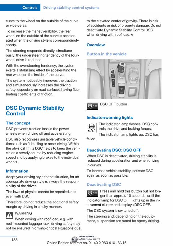
curve to the wheel on the outside of the curveor vice-versa.To increase the maneuverability, the rearwheel on the outside of the curve is acceler‐ated when the driving style is correspondinglysporty.The steering responds directly; simultane‐ously, the understeering tendency of the four-wheel drive is reduced.With the oversteering tendency, the systemexerts a stabilizing effect by accelerating therear wheel on the inside of the curve.The system noticeably improves the tractionand simultaneously increases the drivingsafety, especially on road surfaces having fluc‐tuating coefficients of friction.
DSC Dynamic StabilityControlThe conceptDSC prevents traction loss in the powerwheels when driving off and accelerating.DSC also recognizes unstable vehicle condi‐tions such as fishtailing or nose-diving. Withinthe physical limits DSC helps to keep the vehi‐cle on a steady course by reducing enginespeed and by applying brakes to the individualwheels.
InformationAdapt your driving style to the situation, for anappropriate driving style is always the respon‐sibility of the driver.The laws of physics cannot be repealed, noteven with DSC.Therefore, do not reduce the additional safetymargin by driving in a risky manner.
WARNINGWhen driving with roof load, e.g. with
roof-mounted luggage rack, driving safety maynot be ensured in driving-critical situations due
to the elevated center of gravity. There is riskof accidents or risk of property damage. Do notdeactivate Dynamic Stability Control DSCwhen driving with roof load.◀
Overview
Button in the vehicle
DSC OFF button
Indicator/warning lightsThe indicator lamp flashes: DSC con‐trols the drive and braking forces.The indicator lamp lights up: DSC has
failed.
Deactivating DSC: DSC OFFWhen DSC is deactivated, driving stability isreduced during acceleration and when drivingin curves.To increase vehicle stability, activate DSCagain as soon as possible.
Deactivating DSCPress and hold this button but not lon‐ger than approx. 10 seconds, until the
indicator lamp for DSC OFF lights up in the in‐strument cluster and displays DSC OFF.The DSC system is switched off.The steering and, depending on the equip‐ment, suspension are tuned for sporty driving.
Seite 138
Controls Driving stability control systems
138Online Edition for Part no. 01 40 2 963 410 - VI/15
Information Provided by:
Activating DSCPress button.DSC OFF and the DSC OFF indicator
lamp go out.
Indicator/warning lightsWhen DSC is deactivated, DSC OFF is dis‐played in the instrument cluster.
The indicator lamp lights up: DSC isdeactivated.
DTC Dynamic TractionControlThe conceptThe DTC system is a version of the DSC whereforward momentum is optimized.The system ensures maximum headway onspecial road conditions or loose road surfaces,e.g., unplowed snowy roads, but with some‐what limited driving stability.Activating the Dynamic Traction Control DTCprovides maximum traction. Driving stability islimited during acceleration and when driving incurves.Therefore drive with appropriate caution.You may find it useful to briefly activate DTCunder the following special circumstances:▷ When driving in slush or on uncleared,
snow-covered roads.▷ When freeing vehicle from deep snow or
driving off from loose grounds.▷ When driving with snow chains.
Deactivating/activating DTC DynamicTraction Control
Activating DTCPress button.
TRACTION is displayed in the instrument clus‐ter and the indicator lamp for DSC OFF lightsup.
Deactivating DTCPress button again.TRACTION and the DSC OFF indica‐
tor lamp go out.
Indicator/warning lightsIf DTC is activated, TRACTION is displayed inthe instrument cluster.
The indicator lamp lights up: DTC Dy‐namic Traction Control is activated.
xDrivexDrive is the all-wheel-drive system of your ve‐hicle. Concerted action by the xDrive and DSCfurther optimize traction and driving dynamics.The xDrive all-wheel-drive system variably dis‐tributes the drive forces to the front and rearaxles as demanded by the driving situation androad surface.
Display on the Control Display
Displaying xDrive view1. "Vehicle info"2. "xDrive status"3. "xDrive view"The following information is displayed:▷ With a navigation system: compass display
for the driving direction▷ Pitch attitude with degree and percentage▷ Transverse gradient with degree indication▷ Graphic display for the steering
Seite 139
Driving stability control systems Controls
139Online Edition for Part no. 01 40 2 963 410 - VI/15
Information Provided by:
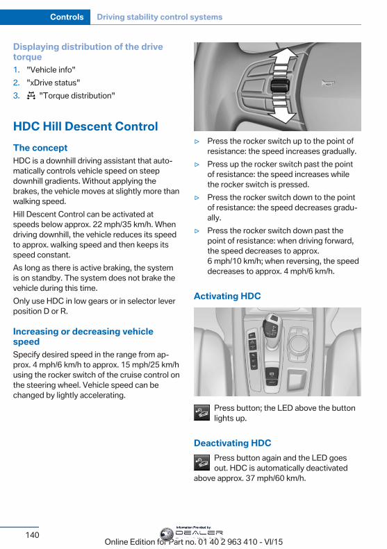
Displaying distribution of the drivetorque1. "Vehicle info"2. "xDrive status"3. "Torque distribution"
HDC Hill Descent ControlThe conceptHDC is a downhill driving assistant that auto‐matically controls vehicle speed on steepdownhill gradients. Without applying thebrakes, the vehicle moves at slightly more thanwalking speed.Hill Descent Control can be activated atspeeds below approx. 22 mph/35 km/h. Whendriving downhill, the vehicle reduces its speedto approx. walking speed and then keeps itsspeed constant.As long as there is active braking, the systemis on standby. The system does not brake thevehicle during this time.Only use HDC in low gears or in selector leverposition D or R.
Increasing or decreasing vehiclespeedSpecify desired speed in the range from ap‐prox. 4 mph/6 km/h to approx. 15 mph/25 km/husing the rocker switch of the cruise control onthe steering wheel. Vehicle speed can bechanged by lightly accelerating.
▷ Press the rocker switch up to the point ofresistance: the speed increases gradually.
▷ Press up the rocker switch past the pointof resistance: the speed increases whilethe rocker switch is pressed.
▷ Press the rocker switch down to the pointof resistance: the speed decreases gradu‐ally.
▷ Press the rocker switch down past thepoint of resistance: when driving forward,the speed decreases to approx.6 mph/10 km/h; when reversing, the speeddecreases to approx. 4 mph/6 km/h.
Activating HDC
Press button; the LED above the buttonlights up.
Deactivating HDCPress button again and the LED goesout. HDC is automatically deactivated
above approx. 37 mph/60 km/h.
Seite 140
Controls Driving stability control systems
140Online Edition for Part no. 01 40 2 963 410 - VI/15
Information Provided by:
Display in the instrument clusterThe selected speed is displayedin the speedometer.▷ Green: the system is actively
braking the vehicle.▷ Orange: the system is on
standby.
MalfunctionA message is displayed in the instrument clus‐ter. HDC is not available, e.g., due to elevatedbrake temperatures.
Active SteeringActive Steering varies the steering angle of thewheels in relation to the steering wheel move‐ment as a function of the speed.At lower speeds, for example during turning ormaneuvering, the steering angle is increased,that is to say the steering becomes more di‐rect.At higher speeds, the steering angle is increas‐ingly reduced.This enables even more precise handling athigh speeds and more responsive steeringwith reduced steering angle at low speeds.
Active roll stabilizationThe conceptThe system reduces the lateral inclination ofthe vehicle that occurs during rapid driving incurves or during quick evasive maneuvers.Driving stability and driving comfort are in‐creased under all driving conditions. The sys‐tem utilizes active stabilizer bars on the frontand rear axles that react immediately to all driv‐ing situations.
ProgramsThe system offers two different programs.Select the programs via the Driving DynamicsControl, refer to page 142.
SPORTSporty tuning for greater driving agility.
COMFORTComfort-oriented tuning for optimal comfort.
Vertical Dynamic ControlThe conceptThis system reduces undesirable vehicle mo‐tion when using a dynamic driving style or trav‐eling on uneven road surfaces.The system enhances driving dynamics andcomfort fitting road surface and driving style.
ProgramsThe system offers several different programs.Select the programs via the Driving DynamicsControl, refer to page 142.
SPORT/SPORT+Consistently sporty control of the shock ab‐sorbers for greater driving agility.
COMFORT/ECO PROBalanced tuning.
Self-leveling suspensionThe conceptThe self-leveling suspension keeps the vehicleheight and ground clearance constant. Theheight of the vehicle at the rear axle is main‐tained at a predefined level under all load con‐ditions.
Seite 141
Driving stability control systems Controls
141Online Edition for Part no. 01 40 2 963 410 - VI/15
Information Provided by:
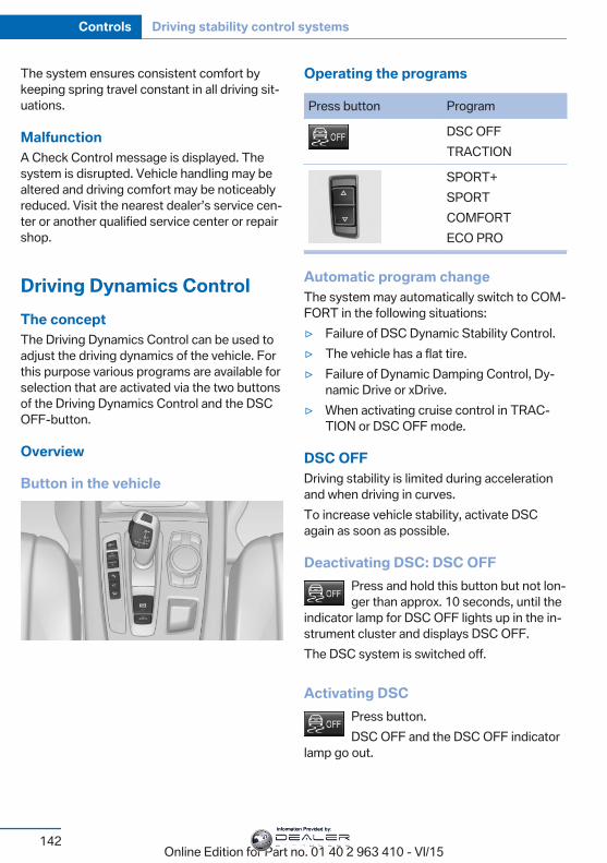
The system ensures consistent comfort bykeeping spring travel constant in all driving sit‐uations.
MalfunctionA Check Control message is displayed. Thesystem is disrupted. Vehicle handling may bealtered and driving comfort may be noticeablyreduced. Visit the nearest dealer’s service cen‐ter or another qualified service center or repairshop.
Driving Dynamics ControlThe conceptThe Driving Dynamics Control can be used toadjust the driving dynamics of the vehicle. Forthis purpose various programs are available forselection that are activated via the two buttonsof the Driving Dynamics Control and the DSCOFF-button.
Overview
Button in the vehicle
Operating the programs
Press button Program
DSC OFFTRACTION
SPORT+SPORTCOMFORTECO PRO
Automatic program changeThe system may automatically switch to COM‐FORT in the following situations:▷ Failure of DSC Dynamic Stability Control.▷ The vehicle has a flat tire.▷ Failure of Dynamic Damping Control, Dy‐
namic Drive or xDrive.▷ When activating cruise control in TRAC‐
TION or DSC OFF mode.
DSC OFFDriving stability is limited during accelerationand when driving in curves.To increase vehicle stability, activate DSCagain as soon as possible.
Deactivating DSC: DSC OFFPress and hold this button but not lon‐ger than approx. 10 seconds, until the
indicator lamp for DSC OFF lights up in the in‐strument cluster and displays DSC OFF.The DSC system is switched off.
Activating DSCPress button.DSC OFF and the DSC OFF indicator
lamp go out.
Seite 142
Controls Driving stability control systems
142Online Edition for Part no. 01 40 2 963 410 - VI/15
Information Provided by:
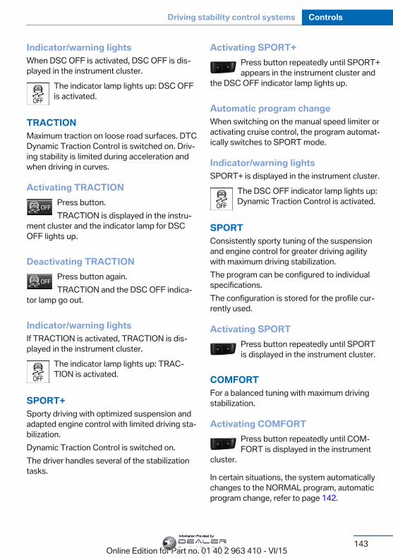
Indicator/warning lightsWhen DSC OFF is activated, DSC OFF is dis‐played in the instrument cluster.
The indicator lamp lights up: DSC OFFis activated.
TRACTIONMaximum traction on loose road surfaces. DTCDynamic Traction Control is switched on. Driv‐ing stability is limited during acceleration andwhen driving in curves.
Activating TRACTIONPress button.TRACTION is displayed in the instru‐
ment cluster and the indicator lamp for DSCOFF lights up.
Deactivating TRACTIONPress button again.TRACTION and the DSC OFF indica‐
tor lamp go out.
Indicator/warning lightsIf TRACTION is activated, TRACTION is dis‐played in the instrument cluster.
The indicator lamp lights up: TRAC‐TION is activated.
SPORT+Sporty driving with optimized suspension andadapted engine control with limited driving sta‐bilization.Dynamic Traction Control is switched on.The driver handles several of the stabilizationtasks.
Activating SPORT+Press button repeatedly until SPORT+appears in the instrument cluster and
the DSC OFF indicator lamp lights up.
Automatic program changeWhen switching on the manual speed limiter oractivating cruise control, the program automat‐ically switches to SPORT mode.
Indicator/warning lightsSPORT+ is displayed in the instrument cluster.
The DSC OFF indicator lamp lights up:Dynamic Traction Control is activated.
SPORTConsistently sporty tuning of the suspensionand engine control for greater driving agilitywith maximum driving stabilization.The program can be configured to individualspecifications.The configuration is stored for the profile cur‐rently used.
Activating SPORTPress button repeatedly until SPORTis displayed in the instrument cluster.
COMFORTFor a balanced tuning with maximum drivingstabilization.
Activating COMFORTPress button repeatedly until COM‐FORT is displayed in the instrument
cluster.
In certain situations, the system automaticallychanges to the NORMAL program, automaticprogram change, refer to page 142.
Seite 143
Driving stability control systems Controls
143Online Edition for Part no. 01 40 2 963 410 - VI/15
Information Provided by:
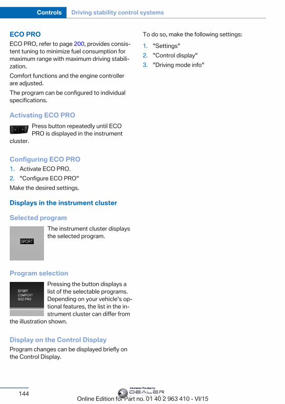
ECO PROECO PRO, refer to page 200, provides consis‐tent tuning to minimize fuel consumption formaximum range with maximum driving stabili‐zation.Comfort functions and the engine controllerare adjusted.The program can be configured to individualspecifications.
Activating ECO PROPress button repeatedly until ECOPRO is displayed in the instrument
cluster.
Configuring ECO PRO1. Activate ECO PRO.2. "Configure ECO PRO"Make the desired settings.
Displays in the instrument cluster
Selected programThe instrument cluster displaysthe selected program.
Program selectionPressing the button displays alist of the selectable programs.Depending on your vehicle's op‐tional features, the list in the in‐strument cluster can differ from
the illustration shown.
Display on the Control DisplayProgram changes can be displayed briefly onthe Control Display.
To do so, make the following settings:
1. "Settings"2. "Control display"3. "Driving mode info"
Seite 144
Controls Driving stability control systems
144Online Edition for Part no. 01 40 2 963 410 - VI/15
Information Provided by:
Driving comfortVehicle features and optionsThis chapter describes all standard, country-specific and optional features offered with theseries. It also describes features that are notnecessarily available in your car, e. g., due tothe selected options or country versions. Thisalso applies to safety-related functions andsystems. The respectively applicable countryprovisions must be observed when using therespective features and systems.
Active Cruise Control withStop & Go function, ACCThe conceptUse this system to select a desired speed thatthe vehicle will maintain automatically on clearroads.To the extent possible, the system automati‐cally adjusts the speed to a slower vehicleahead of you.The distance that the vehicle maintains to thevehicle ahead of you can be varied.For safety reasons, it depends on the speed.To maintain a certain distance, the system au‐tomatically reduces the speed, applies thebrakes lightly, or accelerates again if the vehi‐cle ahead begins moving faster.If the vehicle ahead of you brakes to a halt, andthen proceeds to drive again within a brief pe‐riod, the system is able to detect this within thegiven system limits. Your own vehicle willbrake automatically and then accelerate again.If the vehicle ahead of you drives away againafter a prolonged period, briefly press the ac‐celerator pedal or press the appropriate buttonto reactivate the system. The vehicle will auto‐matically accelerate.
As soon as the road is clear, the vehicle accel‐erates to the desired speed.The speed is also maintained downhill, butmay not be maintained uphill if engine power isinsufficient.
General informationDepending on the driving settings, the featuresof the cruise control can change in certainareas.
InformationWARNINGThe system does not relieve from the
personal responsibility to correctly assess thetraffic situation. Based on the limits of the sys‐tem, it cannot independently react to all trafficsituations. There is risk of an accident. Adjustthe driving style to the traffic conditions. Watchtraffic closely and actively interfere in the re‐spective situations.◀
WARNINGAn unsecured vehicle can put itself into
motion and roll away. There is risk of an acci‐dent. Before exiting, secure the vehicle againstrolling.In order to ensure that the vehicle is securedagainst rolling away, observe the following:▷ Set the parking brake.▷ On uphill grades or on a slope, turn the
front wheels in the direction of the curb.▷ On uphill grades or on a slope, also secure
the vehicle, e.g. with a wheel chock.◀
Seite 145
Driving comfort Controls
145Online Edition for Part no. 01 40 2 963 410 - VI/15
Information Provided by:
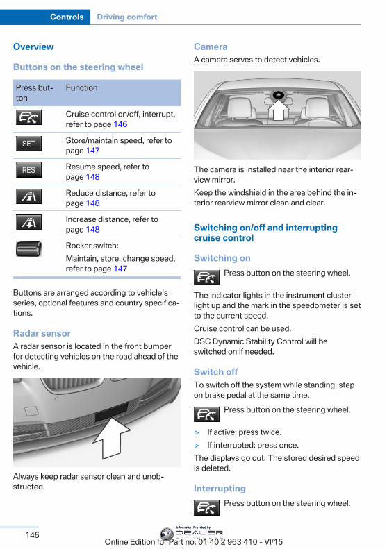
Overview
Buttons on the steering wheel
Press but‐ton
Function
Cruise control on/off, interrupt,refer to page 146
Store/maintain speed, refer topage 147
Resume speed, refer topage 148
Reduce distance, refer topage 148
Increase distance, refer topage 148
Rocker switch:Maintain, store, change speed,refer to page 147
Buttons are arranged according to vehicle'sseries, optional features and country specifica‐tions.
Radar sensorA radar sensor is located in the front bumperfor detecting vehicles on the road ahead of thevehicle.
Always keep radar sensor clean and unob‐structed.
CameraA camera serves to detect vehicles.
The camera is installed near the interior rear‐view mirror.Keep the windshield in the area behind the in‐terior rearview mirror clean and clear.
Switching on/off and interruptingcruise control
Switching onPress button on the steering wheel.
The indicator lights in the instrument clusterlight up and the mark in the speedometer is setto the current speed.Cruise control can be used.DSC Dynamic Stability Control will beswitched on if needed.
Switch offTo switch off the system while standing, stepon brake pedal at the same time.
Press button on the steering wheel.
▷ If active: press twice.▷ If interrupted: press once.The displays go out. The stored desired speedis deleted.
InterruptingPress button on the steering wheel.
Seite 146
Controls Driving comfort
146Online Edition for Part no. 01 40 2 963 410 - VI/15
Information Provided by:
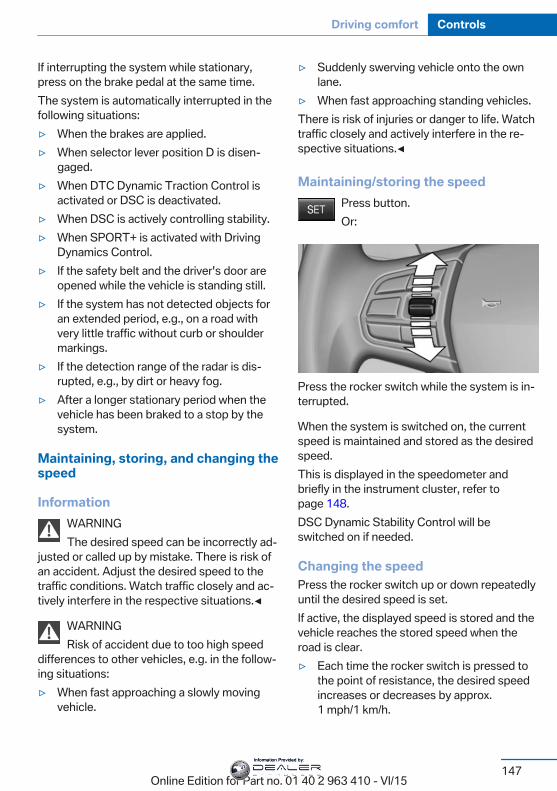
If interrupting the system while stationary,press on the brake pedal at the same time.The system is automatically interrupted in thefollowing situations:▷ When the brakes are applied.▷ When selector lever position D is disen‐
gaged.▷ When DTC Dynamic Traction Control is
activated or DSC is deactivated.▷ When DSC is actively controlling stability.▷ When SPORT+ is activated with Driving
Dynamics Control.▷ If the safety belt and the driver's door are
opened while the vehicle is standing still.▷ If the system has not detected objects for
an extended period, e.g., on a road withvery little traffic without curb or shouldermarkings.
▷ If the detection range of the radar is dis‐rupted, e.g., by dirt or heavy fog.
▷ After a longer stationary period when thevehicle has been braked to a stop by thesystem.
Maintaining, storing, and changing thespeed
InformationWARNINGThe desired speed can be incorrectly ad‐
justed or called up by mistake. There is risk ofan accident. Adjust the desired speed to thetraffic conditions. Watch traffic closely and ac‐tively interfere in the respective situations.◀
WARNINGRisk of accident due to too high speed
differences to other vehicles, e.g. in the follow‐ing situations:▷ When fast approaching a slowly moving
vehicle.
▷ Suddenly swerving vehicle onto the ownlane.
▷ When fast approaching standing vehicles.There is risk of injuries or danger to life. Watchtraffic closely and actively interfere in the re‐spective situations.◀
Maintaining/storing the speedPress button.Or:
Press the rocker switch while the system is in‐terrupted.
When the system is switched on, the currentspeed is maintained and stored as the desiredspeed.This is displayed in the speedometer andbriefly in the instrument cluster, refer topage 148.DSC Dynamic Stability Control will beswitched on if needed.
Changing the speedPress the rocker switch up or down repeatedlyuntil the desired speed is set.If active, the displayed speed is stored and thevehicle reaches the stored speed when theroad is clear.▷ Each time the rocker switch is pressed to
the point of resistance, the desired speedincreases or decreases by approx.1 mph/1 km/h.
Seite 147
Driving comfort Controls
147Online Edition for Part no. 01 40 2 963 410 - VI/15
Information Provided by:
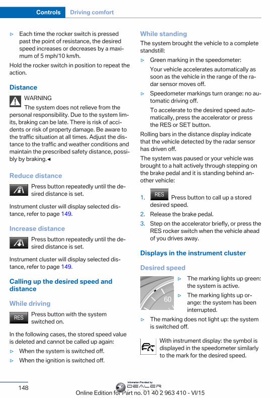
▷ Each time the rocker switch is pressedpast the point of resistance, the desiredspeed increases or decreases by a maxi‐mum of 5 mph/10 km/h.
Hold the rocker switch in position to repeat theaction.
DistanceWARNINGThe system does not relieve from the
personal responsibility. Due to the system lim‐its, braking can be late. There is risk of acci‐dents or risk of property damage. Be aware tothe traffic situation at all times. Adjust the dis‐tance to the traffic and weather conditions andmaintain the prescribed safety distance, possi‐bly by braking.◀
Reduce distancePress button repeatedly until the de‐sired distance is set.
Instrument cluster will display selected dis‐tance, refer to page 149.
Increase distancePress button repeatedly until the de‐sired distance is set.
Instrument cluster will display selected dis‐tance, refer to page 149.
Calling up the desired speed anddistance
While drivingPress button with the systemswitched on.
In the following cases, the stored speed valueis deleted and cannot be called up again:▷ When the system is switched off.▷ When the ignition is switched off.
While standingThe system brought the vehicle to a completestandstill:▷ Green marking in the speedometer:
Your vehicle accelerates automatically assoon as the vehicle in the range of the ra‐dar sensor moves off.
▷ Speedometer markings turn orange: no au‐tomatic driving off.To accelerate to the desired speed auto‐matically, press the accelerator or pressthe RES or SET button.
Rolling bars in the distance display indicatethat the vehicle detected by the radar sensorhas driven off.The system was paused or your vehicle wasbrought to a halt actively through stepping onthe brake pedal and it is standing behind an‐other vehicle:
1. Press button to call up a storeddesired speed.
2. Release the brake pedal.3. Step on the accelerator briefly, or press the
RES rocker switch when the vehicle aheadof you drives away.
Displays in the instrument cluster
Desired speed▷ The marking lights up green:
the system is active.▷ The marking lights up or‐
ange: the system has beeninterrupted.
▷ The marking does not light up: the systemis switched off.
With instrument display: the symbol isdisplayed in the speedometer similarlyto the mark for the desired speed.
Seite 148
Controls Driving comfort
148Online Edition for Part no. 01 40 2 963 410 - VI/15
Information Provided by:
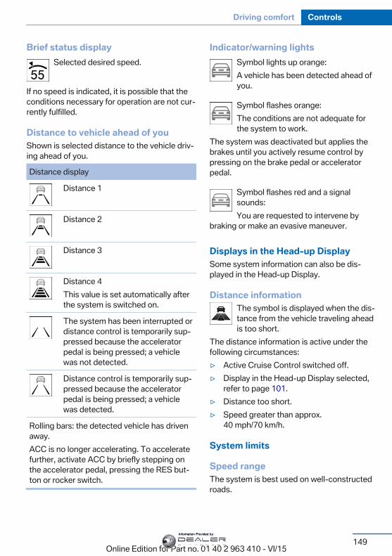
Brief status displaySelected desired speed.
If no speed is indicated, it is possible that theconditions necessary for operation are not cur‐rently fulfilled.
Distance to vehicle ahead of youShown is selected distance to the vehicle driv‐ing ahead of you.
Distance display
Distance 1
Distance 2
Distance 3
Distance 4This value is set automatically afterthe system is switched on.
The system has been interrupted ordistance control is temporarily sup‐pressed because the acceleratorpedal is being pressed; a vehiclewas not detected.
Distance control is temporarily sup‐pressed because the acceleratorpedal is being pressed; a vehiclewas detected.
Rolling bars: the detected vehicle has drivenaway.ACC is no longer accelerating. To acceleratefurther, activate ACC by briefly stepping onthe accelerator pedal, pressing the RES but‐ton or rocker switch.
Indicator/warning lightsSymbol lights up orange:A vehicle has been detected ahead ofyou.
Symbol flashes orange:The conditions are not adequate forthe system to work.
The system was deactivated but applies thebrakes until you actively resume control bypressing on the brake pedal or acceleratorpedal.
Symbol flashes red and a signalsounds:You are requested to intervene by
braking or make an evasive maneuver.
Displays in the Head-up DisplaySome system information can also be dis‐played in the Head-up Display.
Distance informationThe symbol is displayed when the dis‐tance from the vehicle traveling aheadis too short.
The distance information is active under thefollowing circumstances:▷ Active Cruise Control switched off.▷ Display in the Head-up Display selected,
refer to page 101.▷ Distance too short.▷ Speed greater than approx.
40 mph/70 km/h.
System limits
Speed rangeThe system is best used on well-constructedroads.
Seite 149
Driving comfort Controls
149Online Edition for Part no. 01 40 2 963 410 - VI/15
Information Provided by:
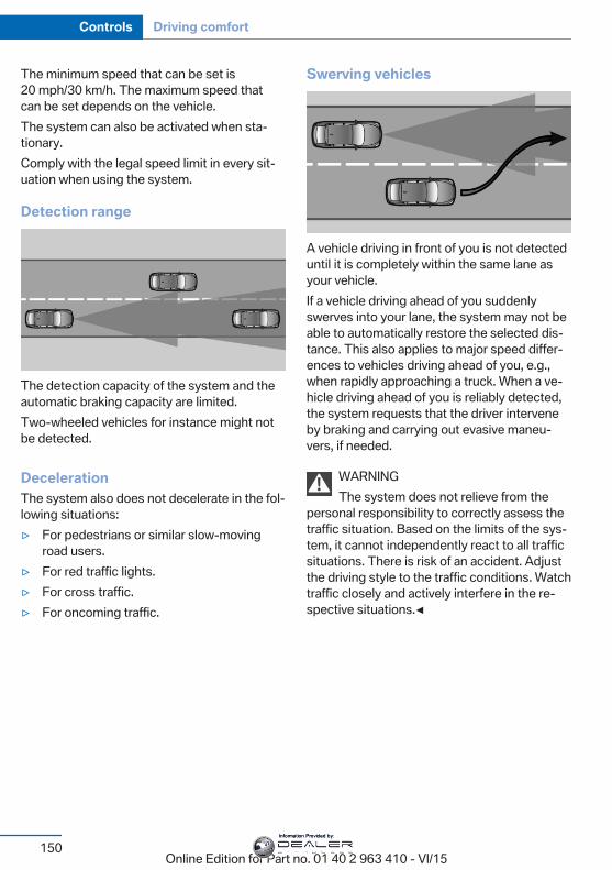
The minimum speed that can be set is20 mph/30 km/h. The maximum speed thatcan be set depends on the vehicle.The system can also be activated when sta‐tionary.Comply with the legal speed limit in every sit‐uation when using the system.
Detection range
The detection capacity of the system and theautomatic braking capacity are limited.Two-wheeled vehicles for instance might notbe detected.
DecelerationThe system also does not decelerate in the fol‐lowing situations:▷ For pedestrians or similar slow-moving
road users.▷ For red traffic lights.▷ For cross traffic.▷ For oncoming traffic.
Swerving vehicles
A vehicle driving in front of you is not detecteduntil it is completely within the same lane asyour vehicle.If a vehicle driving ahead of you suddenlyswerves into your lane, the system may not beable to automatically restore the selected dis‐tance. This also applies to major speed differ‐ences to vehicles driving ahead of you, e.g.,when rapidly approaching a truck. When a ve‐hicle driving ahead of you is reliably detected,the system requests that the driver interveneby braking and carrying out evasive maneu‐vers, if needed.
WARNINGThe system does not relieve from the
personal responsibility to correctly assess thetraffic situation. Based on the limits of the sys‐tem, it cannot independently react to all trafficsituations. There is risk of an accident. Adjustthe driving style to the traffic conditions. Watchtraffic closely and actively interfere in the re‐spective situations.◀
Seite 150
Controls Driving comfort
150Online Edition for Part no. 01 40 2 963 410 - VI/15
Information Provided by:
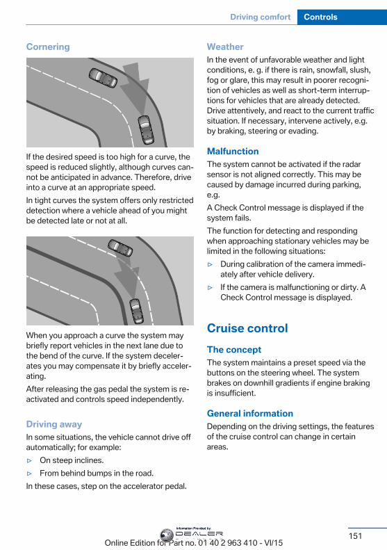
Cornering
If the desired speed is too high for a curve, thespeed is reduced slightly, although curves can‐not be anticipated in advance. Therefore, driveinto a curve at an appropriate speed.In tight curves the system offers only restricteddetection where a vehicle ahead of you mightbe detected late or not at all.
When you approach a curve the system maybriefly report vehicles in the next lane due tothe bend of the curve. If the system deceler‐ates you may compensate it by briefly acceler‐ating.After releasing the gas pedal the system is re‐activated and controls speed independently.
Driving awayIn some situations, the vehicle cannot drive offautomatically; for example:▷ On steep inclines.▷ From behind bumps in the road.In these cases, step on the accelerator pedal.
WeatherIn the event of unfavorable weather and lightconditions, e. g. if there is rain, snowfall, slush,fog or glare, this may result in poorer recogni‐tion of vehicles as well as short-term interrup‐tions for vehicles that are already detected.Drive attentively, and react to the current trafficsituation. If necessary, intervene actively, e.g.by braking, steering or evading.
MalfunctionThe system cannot be activated if the radarsensor is not aligned correctly. This may becaused by damage incurred during parking,e.g.A Check Control message is displayed if thesystem fails.The function for detecting and respondingwhen approaching stationary vehicles may belimited in the following situations:▷ During calibration of the camera immedi‐
ately after vehicle delivery.▷ If the camera is malfunctioning or dirty. A
Check Control message is displayed.
Cruise controlThe conceptThe system maintains a preset speed via thebuttons on the steering wheel. The systembrakes on downhill gradients if engine brakingis insufficient.
General informationDepending on the driving settings, the featuresof the cruise control can change in certainareas.
Seite 151
Driving comfort Controls
151Online Edition for Part no. 01 40 2 963 410 - VI/15
Information Provided by:
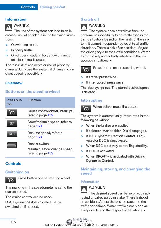
InformationWARNINGThe use of the system can lead to an in‐
creased risk of accidents in the following situa‐tions:▷ On winding roads.▷ In heavy traffic.▷ On slippery roads, in fog, snow or rain, or
on a loose road surface.There is risk of accidents or risk of propertydamage. Only use the system if driving at con‐stant speed is possible.◀
Overview
Buttons on the steering wheel
Press but‐ton
Function
Cruise control on/off, interrupt,refer to page 152
Store/maintain speed, refer topage 153
Resume speed, refer topage 153
Rocker switch:Maintain, store, change speed,refer to page 153
Controls
Switching onPress button on the steering wheel.
The marking in the speedometer is set to thecurrent speed.The cruise control can be used.DSC Dynamic Stability Control will beswitched on if needed.
Switch offWARNINGThe system does not relieve from the
personal responsibility to correctly assess thetraffic situation. Based on the limits of the sys‐tem, it cannot independently react to all trafficsituations. There is risk of an accident. Adjustthe driving style to the traffic conditions. Watchtraffic closely and actively interfere in the re‐spective situations.◀
Press button on the steering wheel.
▷ If active: press twice.▷ If interrupted: press once.The displays go out. The stored desired speedis deleted.
InterruptingWhen active, press the button.
The system is automatically interrupted in thefollowing situations:▷ When the brakes are applied.▷ If selector lever position D is disengaged.▷ If DTC Dynamic Traction Control is acti‐
vated or DSC is deactivated.▷ When DSC is actively controlling stability.▷ If HDC is activated.▷ When SPORT+ is activated with Driving
Dynamics Control.
Maintaining, storing, and changing thespeed
InformationWARNINGThe desired speed can be incorrectly ad‐
justed or called up by mistake. There is risk ofan accident. Adjust the desired speed to thetraffic conditions. Watch traffic closely and ac‐tively interfere in the respective situations.◀
Seite 152
Controls Driving comfort
152Online Edition for Part no. 01 40 2 963 410 - VI/15
Information Provided by:
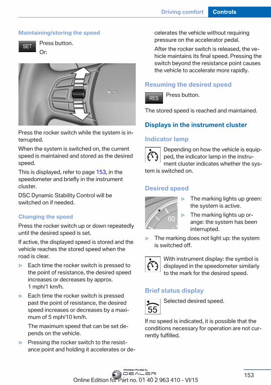
Maintaining/storing the speedPress button.Or:
Press the rocker switch while the system is in‐terrupted.When the system is switched on, the currentspeed is maintained and stored as the desiredspeed.This is displayed, refer to page 153, in thespeedometer and briefly in the instrumentcluster.DSC Dynamic Stability Control will beswitched on if needed.
Changing the speedPress the rocker switch up or down repeatedlyuntil the desired speed is set.If active, the displayed speed is stored and thevehicle reaches the stored speed when theroad is clear.▷ Each time the rocker switch is pressed to
the point of resistance, the desired speedincreases or decreases by approx.1 mph/1 km/h.
▷ Each time the rocker switch is pressedpast the point of resistance, the desiredspeed increases or decreases by a maxi‐mum of 5 mph/10 km/h.The maximum speed that can be set de‐pends on the vehicle.
▷ Pressing the rocker switch to the resist‐ance point and holding it accelerates or de‐
celerates the vehicle without requiringpressure on the accelerator pedal.After the rocker switch is released, the ve‐hicle maintains its final speed. Pressing theswitch beyond the resistance point causesthe vehicle to accelerate more rapidly.
Resuming the desired speedPress button.
The stored speed is reached and maintained.
Displays in the instrument cluster
Indicator lampDepending on how the vehicle is equip‐ped, the indicator lamp in the instru‐ment cluster indicates whether the sys‐
tem is switched on.
Desired speed▷ The marking lights up green:
the system is active.▷ The marking lights up or‐
ange: the system has beeninterrupted.
▷ The marking does not light up: the systemis switched off.
With instrument display: the symbol isdisplayed in the speedometer similarlyto the mark for the desired speed.
Brief status displaySelected desired speed.
If no speed is indicated, it is possible that theconditions necessary for operation are not cur‐rently fulfilled.
Seite 153
Driving comfort Controls
153Online Edition for Part no. 01 40 2 963 410 - VI/15
Information Provided by:
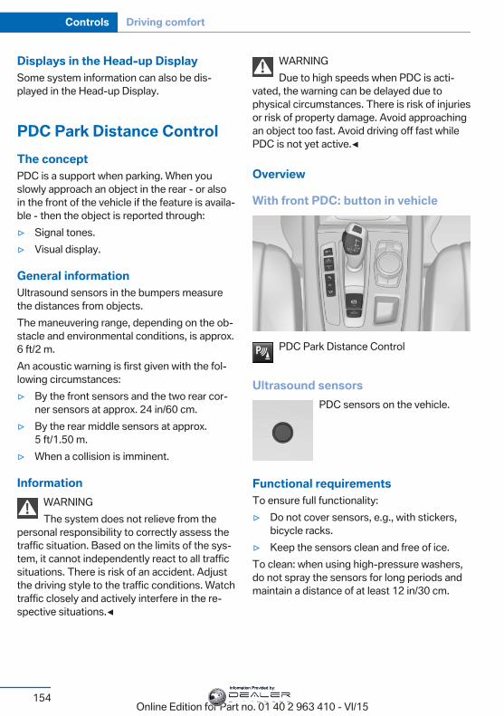
Displays in the Head-up DisplaySome system information can also be dis‐played in the Head-up Display.
PDC Park Distance ControlThe conceptPDC is a support when parking. When youslowly approach an object in the rear - or alsoin the front of the vehicle if the feature is availa‐ble - then the object is reported through:▷ Signal tones.▷ Visual display.
General informationUltrasound sensors in the bumpers measurethe distances from objects.The maneuvering range, depending on the ob‐stacle and environmental conditions, is approx.6 ft/2 m.An acoustic warning is first given with the fol‐lowing circumstances:▷ By the front sensors and the two rear cor‐
ner sensors at approx. 24 in/60 cm.▷ By the rear middle sensors at approx.
5 ft/1.50 m.▷ When a collision is imminent.
InformationWARNINGThe system does not relieve from the
personal responsibility to correctly assess thetraffic situation. Based on the limits of the sys‐tem, it cannot independently react to all trafficsituations. There is risk of an accident. Adjustthe driving style to the traffic conditions. Watchtraffic closely and actively interfere in the re‐spective situations.◀
WARNINGDue to high speeds when PDC is acti‐
vated, the warning can be delayed due tophysical circumstances. There is risk of injuriesor risk of property damage. Avoid approachingan object too fast. Avoid driving off fast whilePDC is not yet active.◀
Overview
With front PDC: button in vehicle
PDC Park Distance Control
Ultrasound sensorsPDC sensors on the vehicle.
Functional requirementsTo ensure full functionality:▷ Do not cover sensors, e.g., with stickers,
bicycle racks.▷ Keep the sensors clean and free of ice.To clean: when using high-pressure washers,do not spray the sensors for long periods andmaintain a distance of at least 12 in/30 cm.
Seite 154
Controls Driving comfort
154Online Edition for Part no. 01 40 2 963 410 - VI/15
Information Provided by:
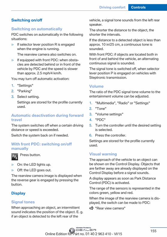
Switching on/off
Switching on automaticallyPDC switches on automatically in the followingsituations:▷ If selector lever position R is engaged
when the engine is running.The rearview camera also switches on.
▷ If equipped with front PDC: when obsta‐cles are detected behind or in front of thevehicle by PDC and the speed is slowerthan approx. 2.5 mph/4 km/h.
You may turn off automatic activation:
1. "Settings"2. "Parking"3. Select setting.
Settings are stored for the profile currentlyused.
Automatic deactivation during forwardtravelThe system switches off when a certain drivingdistance or speed is exceeded.Switch the system back on if needed.
With front PDC: switching on/offmanually
Press button.
▷ On: the LED lights up.▷ Off: the LED goes out.The rearview camera image is displayed whenthe reverse gear is engaged by pressing thebutton.
Display
Signal tonesWhen approaching an object, an intermittentsound indicates the position of the object. E. g.if an object is detected to the left rear of the
vehicle, a signal tone sounds from the left rearspeaker.The shorter the distance to the object, theshorter the intervals.If the distance to a detected object is less thanapprox. 10 in/25 cm, a continuous tone issounded.With front PDC: if objects are located both infront of and behind the vehicle, an alternatingcontinuous signal is sounded.The signal tone is switched off, when selectorlever position P is engaged on vehicles withSteptronic transmission.
VolumeThe ratio of the PDC signal tone volume to theentertainment volume can be adjusted.
1. "Multimedia", "Radio" or "Settings"2. "Tone"3. "Volume settings"4. "PDC"5. Turn the controller until the desired setting
is selected.6. Press the controller.Settings are stored for the profile currentlyused.
Visual warningThe approach of the vehicle to an object canbe shown on the Control Display. Objects thatare farther away are already displayed on theControl Display before a signal sounds.A display appears as soon as Park DistanceControl (PDC) is activated.The range of the sensors is represented in thecolors green, yellow and red.When the image of the rearview camera is dis‐played, the switch can be made to PDC:
"Rear view camera"
Seite 155
Driving comfort Controls
155Online Edition for Part no. 01 40 2 963 410 - VI/15
Information Provided by:
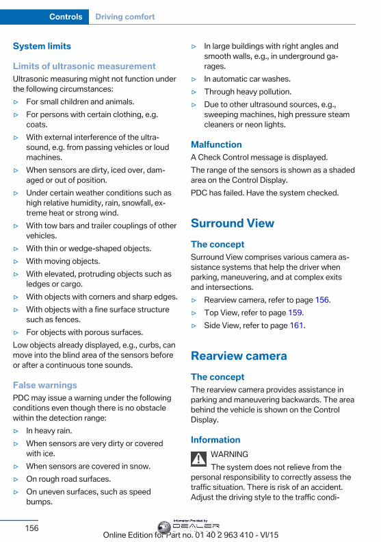
System limits
Limits of ultrasonic measurementUltrasonic measuring might not function underthe following circumstances:▷ For small children and animals.▷ For persons with certain clothing, e.g.
coats.▷ With external interference of the ultra‐
sound, e.g. from passing vehicles or loudmachines.
▷ When sensors are dirty, iced over, dam‐aged or out of position.
▷ Under certain weather conditions such ashigh relative humidity, rain, snowfall, ex‐treme heat or strong wind.
▷ With tow bars and trailer couplings of othervehicles.
▷ With thin or wedge-shaped objects.▷ With moving objects.▷ With elevated, protruding objects such as
ledges or cargo.▷ With objects with corners and sharp edges.▷ With objects with a fine surface structure
such as fences.▷ For objects with porous surfaces.Low objects already displayed, e.g., curbs, canmove into the blind area of the sensors beforeor after a continuous tone sounds.
False warningsPDC may issue a warning under the followingconditions even though there is no obstaclewithin the detection range:▷ In heavy rain.▷ When sensors are very dirty or covered
with ice.▷ When sensors are covered in snow.▷ On rough road surfaces.▷ On uneven surfaces, such as speed
bumps.
▷ In large buildings with right angles andsmooth walls, e.g., in underground ga‐rages.
▷ In automatic car washes.▷ Through heavy pollution.▷ Due to other ultrasound sources, e.g.,
sweeping machines, high pressure steamcleaners or neon lights.
MalfunctionA Check Control message is displayed.The range of the sensors is shown as a shadedarea on the Control Display.PDC has failed. Have the system checked.
Surround ViewThe conceptSurround View comprises various camera as‐sistance systems that help the driver whenparking, maneuvering, and at complex exitsand intersections.▷ Rearview camera, refer to page 156.▷ Top View, refer to page 159.▷ Side View, refer to page 161.
Rearview cameraThe conceptThe rearview camera provides assistance inparking and maneuvering backwards. The areabehind the vehicle is shown on the ControlDisplay.
InformationWARNINGThe system does not relieve from the
personal responsibility to correctly assess thetraffic situation. There is risk of an accident.Adjust the driving style to the traffic condi‐
Seite 156
Controls Driving comfort
156Online Edition for Part no. 01 40 2 963 410 - VI/15
Information Provided by:
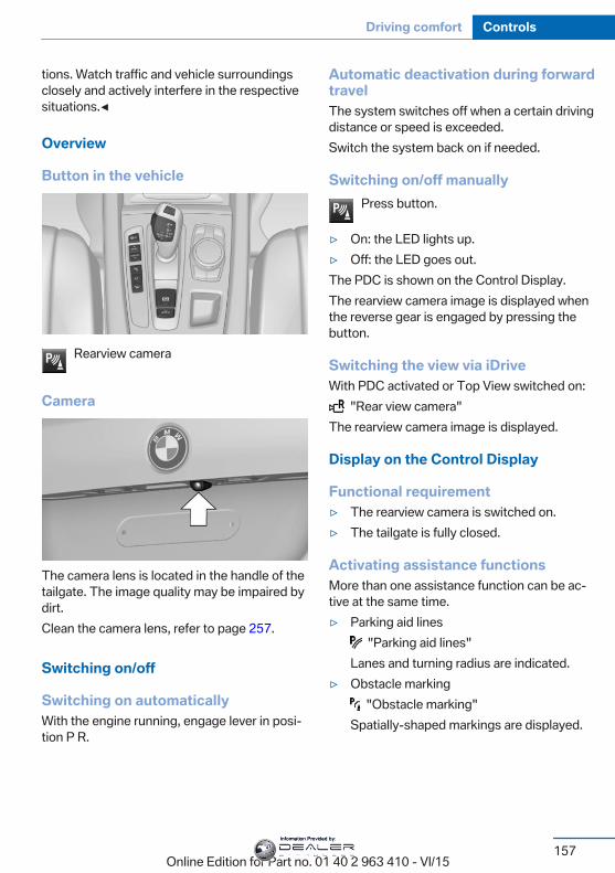
tions. Watch traffic and vehicle surroundingsclosely and actively interfere in the respectivesituations.◀
Overview
Button in the vehicle
Rearview camera
Camera
The camera lens is located in the handle of thetailgate. The image quality may be impaired bydirt.Clean the camera lens, refer to page 257.
Switching on/off
Switching on automaticallyWith the engine running, engage lever in posi‐tion P R.
Automatic deactivation during forwardtravelThe system switches off when a certain drivingdistance or speed is exceeded.Switch the system back on if needed.
Switching on/off manuallyPress button.
▷ On: the LED lights up.▷ Off: the LED goes out.The PDC is shown on the Control Display.The rearview camera image is displayed whenthe reverse gear is engaged by pressing thebutton.
Switching the view via iDriveWith PDC activated or Top View switched on:
"Rear view camera"The rearview camera image is displayed.
Display on the Control Display
Functional requirement▷ The rearview camera is switched on.▷ The tailgate is fully closed.
Activating assistance functionsMore than one assistance function can be ac‐tive at the same time.▷ Parking aid lines
"Parking aid lines"Lanes and turning radius are indicated.
▷ Obstacle marking "Obstacle marking"
Spatially-shaped markings are displayed.
Seite 157
Driving comfort Controls
157Online Edition for Part no. 01 40 2 963 410 - VI/15
Information Provided by:
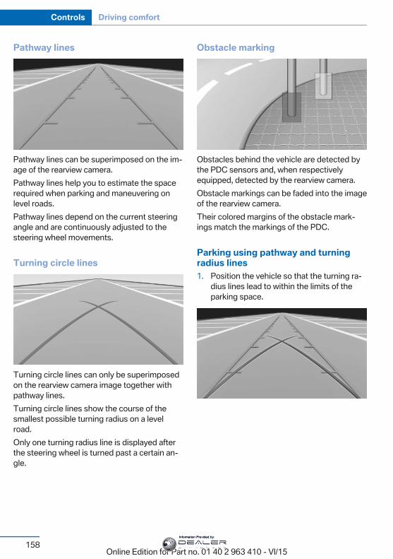
Pathway lines
Pathway lines can be superimposed on the im‐age of the rearview camera.Pathway lines help you to estimate the spacerequired when parking and maneuvering onlevel roads.Pathway lines depend on the current steeringangle and are continuously adjusted to thesteering wheel movements.
Turning circle lines
Turning circle lines can only be superimposedon the rearview camera image together withpathway lines.Turning circle lines show the course of thesmallest possible turning radius on a levelroad.Only one turning radius line is displayed afterthe steering wheel is turned past a certain an‐gle.
Obstacle marking
Obstacles behind the vehicle are detected bythe PDC sensors and, when respectivelyequipped, detected by the rearview camera.Obstacle markings can be faded into the imageof the rearview camera.Their colored margins of the obstacle mark‐ings match the markings of the PDC.
Parking using pathway and turningradius lines1. Position the vehicle so that the turning ra‐
dius lines lead to within the limits of theparking space.
Seite 158
Controls Driving comfort
158Online Edition for Part no. 01 40 2 963 410 - VI/15
Information Provided by:
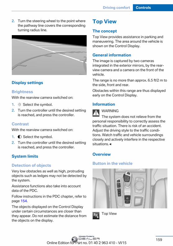
2. Turn the steering wheel to the point wherethe pathway line covers the correspondingturning radius line.
Display settings
BrightnessWith the rearview camera switched on:
1. Select the symbol.2. Turn the controller until the desired setting
is reached, and press the controller.
ContrastWith the rearview camera switched on:
1. Select the symbol.2. Turn the controller until the desired setting
is reached, and press the controller.
System limits
Detection of objectsVery low obstacles as well as high, protrudingobjects such as ledges may not be detected bythe system.Assistance functions also take into accountdata of the PDC.Follow instructions in the PDC chapter, refer topage 154.The objects displayed on the Control Displayunder certain circumstances are closer thanthey appear. Do not estimate the distance fromthe objects on the display.
Top ViewThe conceptTop View provides assistance in parking andmaneuvering. The area around the vehicle isshown on the Control Display.
General informationThe image is captured by two camerasintegrated in the exterior mirrors, by the rear‐view camera and a camera on the front of thevehicle.The range is no more than approx. 6.5 ft/2 m tothe side, front and rear.Obstacles within this range are thus displayedearly on the Control Display.
InformationWARNINGThe system does not relieve from the
personal responsibility to correctly assess thetraffic situation. There is risk of an accident.Adjust the driving style to the traffic condi‐tions. Watch traffic and vehicle surroundingsclosely and actively interfere in the respectivesituations.◀
Overview
Button in the vehicle
Top View
Seite 159
Driving comfort Controls
159Online Edition for Part no. 01 40 2 963 410 - VI/15
Information Provided by:
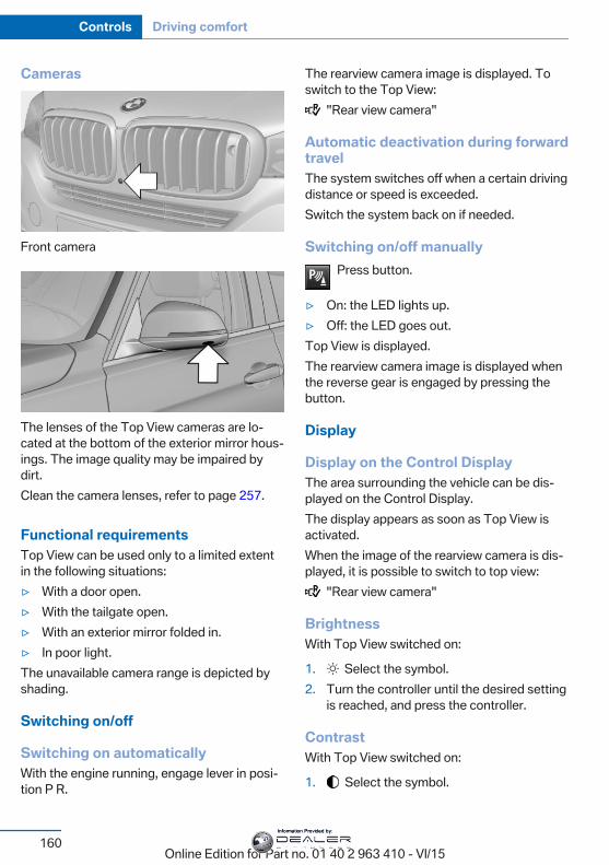
Cameras
Front camera
The lenses of the Top View cameras are lo‐cated at the bottom of the exterior mirror hous‐ings. The image quality may be impaired bydirt.Clean the camera lenses, refer to page 257.
Functional requirementsTop View can be used only to a limited extentin the following situations:▷ With a door open.▷ With the tailgate open.▷ With an exterior mirror folded in.▷ In poor light.The unavailable camera range is depicted byshading.
Switching on/off
Switching on automaticallyWith the engine running, engage lever in posi‐tion P R.
The rearview camera image is displayed. Toswitch to the Top View:
"Rear view camera"
Automatic deactivation during forwardtravelThe system switches off when a certain drivingdistance or speed is exceeded.Switch the system back on if needed.
Switching on/off manuallyPress button.
▷ On: the LED lights up.▷ Off: the LED goes out.Top View is displayed.The rearview camera image is displayed whenthe reverse gear is engaged by pressing thebutton.
Display
Display on the Control DisplayThe area surrounding the vehicle can be dis‐played on the Control Display.The display appears as soon as Top View isactivated.When the image of the rearview camera is dis‐played, it is possible to switch to top view:
"Rear view camera"
BrightnessWith Top View switched on:
1. Select the symbol.2. Turn the controller until the desired setting
is reached, and press the controller.
ContrastWith Top View switched on:
1. Select the symbol.
Seite 160
Controls Driving comfort
160Online Edition for Part no. 01 40 2 963 410 - VI/15
Information Provided by:
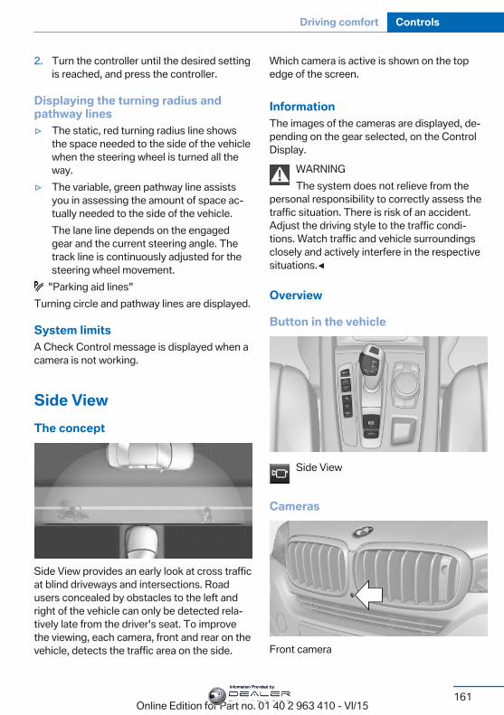
2. Turn the controller until the desired settingis reached, and press the controller.
Displaying the turning radius andpathway lines▷ The static, red turning radius line shows
the space needed to the side of the vehiclewhen the steering wheel is turned all theway.
▷ The variable, green pathway line assistsyou in assessing the amount of space ac‐tually needed to the side of the vehicle.The lane line depends on the engagedgear and the current steering angle. Thetrack line is continuously adjusted for thesteering wheel movement.
"Parking aid lines"Turning circle and pathway lines are displayed.
System limitsA Check Control message is displayed when acamera is not working.
Side ViewThe concept
Side View provides an early look at cross trafficat blind driveways and intersections. Roadusers concealed by obstacles to the left andright of the vehicle can only be detected rela‐tively late from the driver's seat. To improvethe viewing, each camera, front and rear on thevehicle, detects the traffic area on the side.
Which camera is active is shown on the topedge of the screen.
InformationThe images of the cameras are displayed, de‐pending on the gear selected, on the ControlDisplay.
WARNINGThe system does not relieve from the
personal responsibility to correctly assess thetraffic situation. There is risk of an accident.Adjust the driving style to the traffic condi‐tions. Watch traffic and vehicle surroundingsclosely and actively interfere in the respectivesituations.◀
Overview
Button in the vehicle
Side View
Cameras
Front camera
Seite 161
Driving comfort Controls
161Online Edition for Part no. 01 40 2 963 410 - VI/15
Information Provided by:
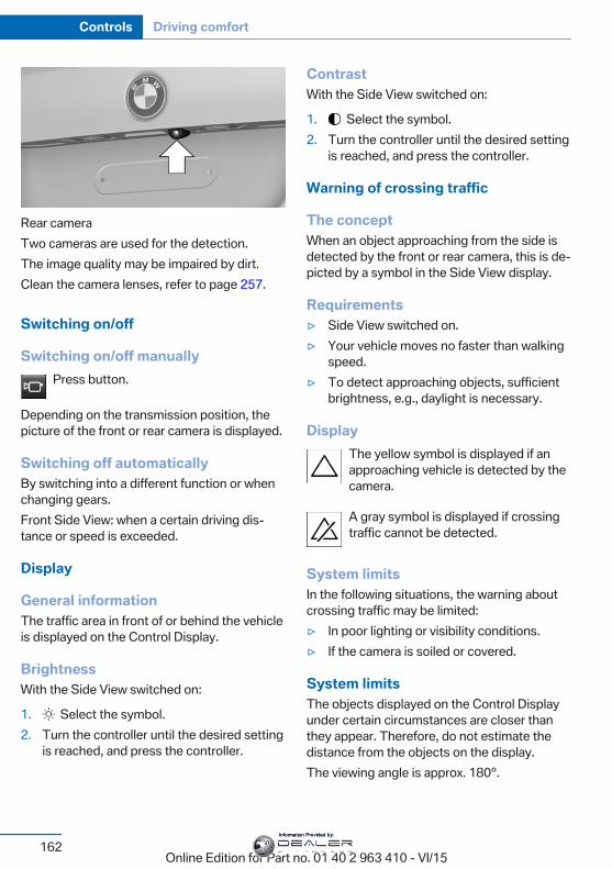
Rear cameraTwo cameras are used for the detection.The image quality may be impaired by dirt.Clean the camera lenses, refer to page 257.
Switching on/off
Switching on/off manuallyPress button.
Depending on the transmission position, thepicture of the front or rear camera is displayed.
Switching off automaticallyBy switching into a different function or whenchanging gears.Front Side View: when a certain driving dis‐tance or speed is exceeded.
Display
General informationThe traffic area in front of or behind the vehicleis displayed on the Control Display.
BrightnessWith the Side View switched on:
1. Select the symbol.2. Turn the controller until the desired setting
is reached, and press the controller.
ContrastWith the Side View switched on:
1. Select the symbol.2. Turn the controller until the desired setting
is reached, and press the controller.
Warning of crossing traffic
The conceptWhen an object approaching from the side isdetected by the front or rear camera, this is de‐picted by a symbol in the Side View display.
Requirements▷ Side View switched on.▷ Your vehicle moves no faster than walking
speed.▷ To detect approaching objects, sufficient
brightness, e.g., daylight is necessary.
DisplayThe yellow symbol is displayed if anapproaching vehicle is detected by thecamera.
A gray symbol is displayed if crossingtraffic cannot be detected.
System limitsIn the following situations, the warning aboutcrossing traffic may be limited:▷ In poor lighting or visibility conditions.▷ If the camera is soiled or covered.
System limitsThe objects displayed on the Control Displayunder certain circumstances are closer thanthey appear. Therefore, do not estimate thedistance from the objects on the display.The viewing angle is approx. 180°.
Seite 162
Controls Driving comfort
162Online Edition for Part no. 01 40 2 963 410 - VI/15
Information Provided by:
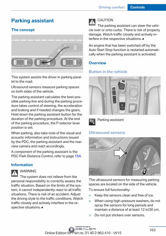
Parking assistantThe concept
This system assists the driver in parking paral‐lel to the road.Ultrasound sensors measure parking spaceson both sides of the vehicle.The parking assistant calculates the best pos‐sible parking line and during the parking proce‐dure takes control of steering, the accelerationand braking and if needed changes the gears.Hold down the parking assistant button for theduration of the parking procedure. At the endof the parking procedure, the P selector leverposition is set.When parking, also take note of the visual andacoustic information and instructions issuedby the PDC, the parking assistant and the rear‐view camera and react accordingly.A component of the parking assistant is thePDC Park Distance Control, refer to page 154.
InformationWARNINGThe system does not relieve from the
personal responsibility to correctly assess thetraffic situation. Based on the limits of the sys‐tem, it cannot independently react to all trafficsituations. There is risk of an accident. Adjustthe driving style to the traffic conditions. Watchtraffic closely and actively interfere in the re‐spective situations.◀
CAUTIONThe parking assistant can steer the vehi‐
cle over or onto curbs. There is risk of propertydamage. Watch traffic closely and actively in‐terfere in the respective situations.◀
An engine that has been switched off by theAuto Start Stop function is restarted automati‐cally when the parking assistant is activated.
Overview
Button in the vehicle
Parking assistant
Ultrasound sensors
The ultrasound sensors for measuring parkingspaces are located on the side of the vehicle.To ensure full functionality:▷ Keep the sensors clean and free of ice.▷ When using high-pressure washers, do not
spray the sensors for long periods andmaintain a distance of at least 12 in/30 cm.
▷ Do not put stickers over sensors.
Seite 163
Driving comfort Controls
163Online Edition for Part no. 01 40 2 963 410 - VI/15
Information Provided by:
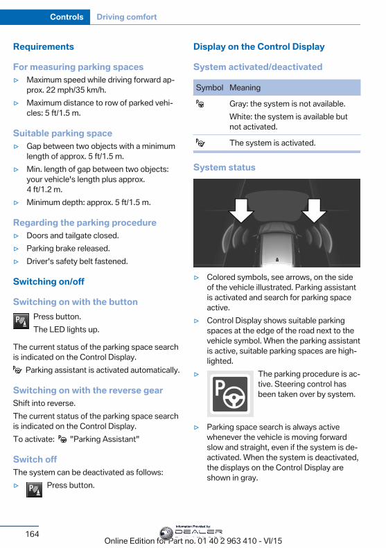
Requirements
For measuring parking spaces▷ Maximum speed while driving forward ap‐
prox. 22 mph/35 km/h.▷ Maximum distance to row of parked vehi‐
cles: 5 ft/1.5 m.
Suitable parking space▷ Gap between two objects with a minimum
length of approx. 5 ft/1.5 m.▷ Min. length of gap between two objects:
your vehicle's length plus approx.4 ft/1.2 m.
▷ Minimum depth: approx. 5 ft/1.5 m.
Regarding the parking procedure▷ Doors and tailgate closed.▷ Parking brake released.▷ Driver's safety belt fastened.
Switching on/off
Switching on with the buttonPress button.The LED lights up.
The current status of the parking space searchis indicated on the Control Display.
Parking assistant is activated automatically.
Switching on with the reverse gearShift into reverse.The current status of the parking space searchis indicated on the Control Display.To activate: "Parking Assistant"
Switch offThe system can be deactivated as follows:▷ Press button.
Display on the Control Display
System activated/deactivated
Symbol Meaning
Gray: the system is not available.White: the system is available butnot activated.
The system is activated.
System status
▷ Colored symbols, see arrows, on the sideof the vehicle illustrated. Parking assistantis activated and search for parking spaceactive.
▷ Control Display shows suitable parkingspaces at the edge of the road next to thevehicle symbol. When the parking assistantis active, suitable parking spaces are high‐lighted.
▷ The parking procedure is ac‐tive. Steering control hasbeen taken over by system.
▷ Parking space search is always activewhenever the vehicle is moving forwardslow and straight, even if the system is de‐activated. When the system is deactivated,the displays on the Control Display areshown in gray.
Seite 164
Controls Driving comfort
164Online Edition for Part no. 01 40 2 963 410 - VI/15
Information Provided by:
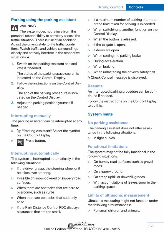
Parking using the parking assistantWARNINGThe system does not relieve from the
personal responsibility to correctly assess thetraffic situation. There is risk of an accident.Adjust the driving style to the traffic condi‐tions. Watch traffic and vehicle surroundingsclosely and actively interfere in the respectivesituations.◀
1. Switch on the parking assistant and acti‐vate it if needed.The status of the parking space search isindicated on the Control Display.
2. Follow the instructions on the Control Dis‐play.The end of the parking procedure is indi‐cated on the Control Display.
3. Adjust the parking position yourself ifneeded.
Interrupting manuallyThe parking assistant can be interrupted at anytime:▷ "Parking Assistant" Select the symbol
on the Control Display.▷ Press button.
Interrupting automaticallyThe system is interrupted automatically in thefollowing situations:▷ If the driver grasps the steering wheel or if
he takes over steering.▷ Possible on snow-covered or slippery road
surfaces.▷ When there are obstacles that are hard to
overcome, such as curbs.▷ When there are obstacles that suddenly
arise.▷ If the Park Distance Control PDC displays
clearances that are too small.
▷ If a maximum number of parking attemptsor the time taken for parking is exceeded.
▷ When switching to another function on theControl Display.
▷ When the button is released.▷ If the tailgate is open.▷ If doors are open.▷ When setting the parking brake.▷ During acceleration.▷ When braking.▷ When unfastening the driver's safety belt.A Check Control message is displayed.
ResumeAn interrupted parking procedure can be con‐tinued if needed.Follow the instructions on the Control Displayto do this.
System limits
No parking assistanceThe parking assistant does not offer assis‐tance in the following situations:▷ In tight curves.
Functional limitationsThe system may not be fully functional in thefollowing situations:▷ On bumpy road surfaces such as gravel
roads.▷ On slippery ground.▷ On steep uphill or downhill grades.▷ With accumulations of leaves/snow in the
parking space.
Limits of ultrasonic measurementUltrasonic measuring might not function underthe following circumstances:▷ For small children and animals.
Seite 165
Driving comfort Controls
165Online Edition for Part no. 01 40 2 963 410 - VI/15
Information Provided by:
▷ For persons with certain clothing, e.g.coats.
▷ With external interference of the ultra‐sound, e.g. from passing vehicles or loudmachines.
▷ When sensors are dirty, iced over, dam‐aged or out of position.
▷ Under certain weather conditions such ashigh relative humidity, rain, snowfall, ex‐treme heat or strong wind.
▷ With tow bars and trailer couplings of othervehicles.
▷ With thin or wedge-shaped objects.▷ With moving objects.▷ With elevated, protruding objects such as
ledges or cargo.▷ With objects with corners and sharp edges.▷ With objects with a fine surface structure
such as fences.▷ For objects with porous surfaces.Low objects already displayed, e.g., curbs, canmove into the blind area of the sensors beforeor after a continuous tone sounds.It can happen that parking spaces are detectedthat are not suitable or suitable parking spacesare not detected.
MalfunctionA Check Control message is displayed.The parking assistant failed. Have the systemchecked.
Seite 166
Controls Driving comfort
166Online Edition for Part no. 01 40 2 963 410 - VI/15
Information Provided by:
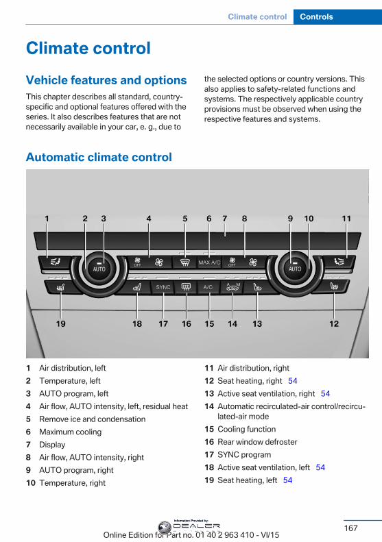
Climate controlVehicle features and optionsThis chapter describes all standard, country-specific and optional features offered with theseries. It also describes features that are notnecessarily available in your car, e. g., due to
the selected options or country versions. Thisalso applies to safety-related functions andsystems. The respectively applicable countryprovisions must be observed when using therespective features and systems.
Automatic climate control
1 Air distribution, left2 Temperature, left3 AUTO program, left4 Air flow, AUTO intensity, left, residual heat5 Remove ice and condensation6 Maximum cooling7 Display8 Air flow, AUTO intensity, right9 AUTO program, right10 Temperature, right
11 Air distribution, right12 Seat heating, right 5413 Active seat ventilation, right 5414 Automatic recirculated-air control/recircu‐
lated-air mode15 Cooling function16 Rear window defroster17 SYNC program18 Active seat ventilation, left 5419 Seat heating, left 54
Seite 167
Climate control Controls
167Online Edition for Part no. 01 40 2 963 410 - VI/15
Information Provided by:
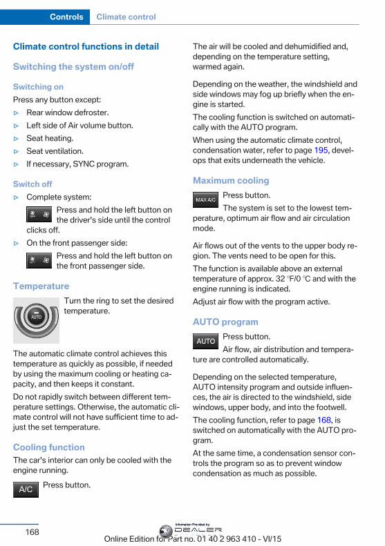
Climate control functions in detail
Switching the system on/off
Switching onPress any button except:▷ Rear window defroster.▷ Left side of Air volume button.▷ Seat heating.▷ Seat ventilation.▷ If necessary, SYNC program.
Switch off▷ Complete system:
Press and hold the left button onthe driver's side until the control
clicks off.▷ On the front passenger side:
Press and hold the left button onthe front passenger side.
TemperatureTurn the ring to set the desiredtemperature.
The automatic climate control achieves thistemperature as quickly as possible, if neededby using the maximum cooling or heating ca‐pacity, and then keeps it constant.Do not rapidly switch between different tem‐perature settings. Otherwise, the automatic cli‐mate control will not have sufficient time to ad‐just the set temperature.
Cooling functionThe car's interior can only be cooled with theengine running.
Press button.
The air will be cooled and dehumidified and,depending on the temperature setting,warmed again.
Depending on the weather, the windshield andside windows may fog up briefly when the en‐gine is started.The cooling function is switched on automati‐cally with the AUTO program.When using the automatic climate control,condensation water, refer to page 195, devel‐ops that exits underneath the vehicle.
Maximum coolingPress button.The system is set to the lowest tem‐
perature, optimum air flow and air circulationmode.
Air flows out of the vents to the upper body re‐gion. The vents need to be open for this.The function is available above an externaltemperature of approx. 32 ℉/0 ℃ and with theengine running is indicated.Adjust air flow with the program active.
AUTO programPress button.Air flow, air distribution and tempera‐
ture are controlled automatically.
Depending on the selected temperature,AUTO intensity program and outside influen‐ces, the air is directed to the windshield, sidewindows, upper body, and into the footwell.The cooling function, refer to page 168, isswitched on automatically with the AUTO pro‐gram.At the same time, a condensation sensor con‐trols the program so as to prevent windowcondensation as much as possible.
Seite 168
Controls Climate control
168Online Edition for Part no. 01 40 2 963 410 - VI/15
Information Provided by:
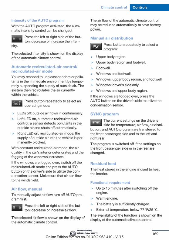
Intensity of the AUTO programWith the AUTO program activated, the auto‐matic intensity control can be changed.
Press the left or right side of the but‐ton: decrease or increase the inten‐
sity.
The selected intensity is shown on the displayof the automatic climate control.
Automatic recirculated-air control/recirculated-air modeYou may respond to unpleasant odors or pollu‐tants in the immediate environment by tempo‐rarily suspending the supply of outside air. Thesystem then recirculates the air currentlywithin the vehicle.
Press button repeatedly to select anoperating mode:
▷ LEDs off: outside air flows in continuously.▷ Left LED on, automatic recirculated-air
control: a sensor detects pollutants in theoutside air and shuts off automatically.
▷ Right LED on, recirculated-air mode: thesupply of outside air into the vehicle is per‐manently blocked.
With constant recirculated-air mode, the airquality in the car's interior deteriorates and thefogging of the windows increases.If the windows are fogged over, switch off therecirculated-air mode and press the AUTObutton on the driver's side to utilize the con‐densation sensor. Make sure that air can flowto the windshield.
Air flow, manualTo manually adjust air flow turn off AUTO pro‐gram first.
Press the left or right side of the but‐ton: decrease or increase air flow.
The selected air flow is shown on the display ofthe automatic climate control.
The air flow of the automatic climate controlmay be reduced automatically to save batterypower.
Manual air distributionPress button repeatedly to select aprogram:
▷ Upper body region.▷ Upper body region and footwell.▷ Footwell.▷ Windows and footwell.▷ Windows, upper body region, and footwell.▷ Windows: driver's side only.▷ Windows and upper body region.If the windows are fogged over, press theAUTO button on the driver's side to utilize thecondensation sensor.
SYNC programThe current settings on the driver'sside for temperature, air flow, air distri‐
bution, and AUTO program are transferred tothe front passenger side and to the left andright rear.The program is switched off if the settings onthe front passenger side or in the rear arechanged.
Residual heatThe heat stored in the engine is used to heatthe interior.
Functional requirement▷ Up to 15 minutes after switching off the
engine.▷ Warm engine.▷ The battery is sufficiently charged.▷ External temperature below 77 ℉/25 ℃.The availability of the function is shown on thedisplay of the automatic climate control.
Seite 169
Climate control Controls
169Online Edition for Part no. 01 40 2 963 410 - VI/15
Information Provided by:
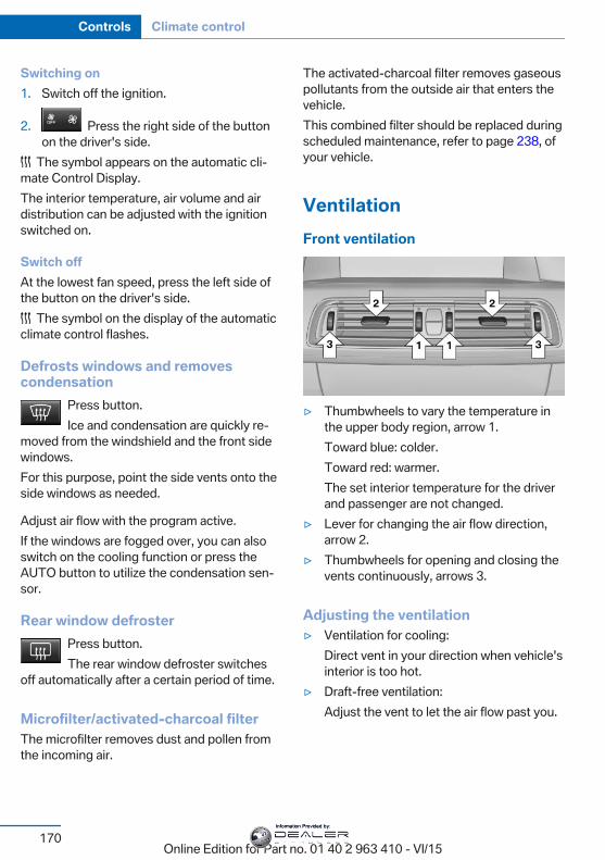
Switching on1. Switch off the ignition.
2. Press the right side of the buttonon the driver's side.
The symbol appears on the automatic cli‐mate Control Display.The interior temperature, air volume and airdistribution can be adjusted with the ignitionswitched on.
Switch offAt the lowest fan speed, press the left side ofthe button on the driver's side.
The symbol on the display of the automaticclimate control flashes.
Defrosts windows and removescondensation
Press button.Ice and condensation are quickly re‐
moved from the windshield and the front sidewindows.For this purpose, point the side vents onto theside windows as needed.
Adjust air flow with the program active.If the windows are fogged over, you can alsoswitch on the cooling function or press theAUTO button to utilize the condensation sen‐sor.
Rear window defrosterPress button.The rear window defroster switches
off automatically after a certain period of time.
Microfilter/activated-charcoal filterThe microfilter removes dust and pollen fromthe incoming air.
The activated-charcoal filter removes gaseouspollutants from the outside air that enters thevehicle.This combined filter should be replaced duringscheduled maintenance, refer to page 238, ofyour vehicle.
VentilationFront ventilation
▷ Thumbwheels to vary the temperature inthe upper body region, arrow 1.Toward blue: colder.Toward red: warmer.The set interior temperature for the driverand passenger are not changed.
▷ Lever for changing the air flow direction,arrow 2.
▷ Thumbwheels for opening and closing thevents continuously, arrows 3.
Adjusting the ventilation▷ Ventilation for cooling:
Direct vent in your direction when vehicle'sinterior is too hot.
▷ Draft-free ventilation:Adjust the vent to let the air flow past you.
Seite 170
Controls Climate control
170Online Edition for Part no. 01 40 2 963 410 - VI/15
Information Provided by:
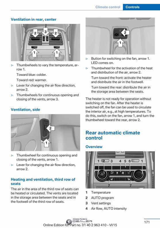
Ventilation in rear, center
▷ Thumbwheels to vary the temperature, ar‐row 1.Toward blue: colder.Toward red: warmer.
▷ Lever for changing the air flow direction,arrow 2.
▷ Thumbwheels for continuous opening andclosing of the vents, arrow 3.
Ventilation, side
▷ Thumbwheel for continuous opening andclosing of the vents, arrow 1.
▷ Lever for changing the air flow direction,arrow 2.
Heating and ventilation, third row ofseatsThe air in the area of the third row of seats canbe heated or circulated. The vents are locatedin the storage area between the seats and inthe footwell of the third row of seats.
▷ Button for switching on the fan, arrow 1.LED comes on.
▷ Thumbwheel for the activation of the heatand distribution of the air, arrow 2.Turn toward the front: activate the heaterand distribute the air in the footwell.Turn toward the rear: distribute the air inthe storage area between the seats.
The heater is not ready for operation withoutswitching on the fan. After the heater isswitched off, the fan can be used to circulatethe interior air, e.g., at high temperatures. Todo this, switch on the fan, arrow 1, and turn thethumbwheel toward the rear, arrow 2.
Rear automatic climatecontrolOverview
1 Temperature2 AUTO program3 Vent settings4 Air flow, AUTO intensity
Seite 171
Climate control Controls
171Online Edition for Part no. 01 40 2 963 410 - VI/15
Information Provided by:
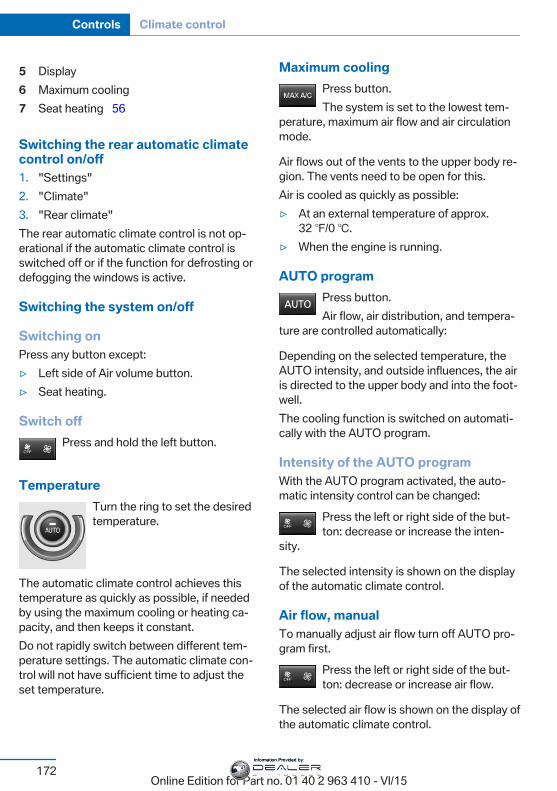
5 Display6 Maximum cooling7 Seat heating 56
Switching the rear automatic climatecontrol on/off1. "Settings"2. "Climate"3. "Rear climate"The rear automatic climate control is not op‐erational if the automatic climate control isswitched off or if the function for defrosting ordefogging the windows is active.
Switching the system on/off
Switching onPress any button except:▷ Left side of Air volume button.▷ Seat heating.
Switch offPress and hold the left button.
TemperatureTurn the ring to set the desiredtemperature.
The automatic climate control achieves thistemperature as quickly as possible, if neededby using the maximum cooling or heating ca‐pacity, and then keeps it constant.Do not rapidly switch between different tem‐perature settings. The automatic climate con‐trol will not have sufficient time to adjust theset temperature.
Maximum coolingPress button.The system is set to the lowest tem‐
perature, maximum air flow and air circulationmode.
Air flows out of the vents to the upper body re‐gion. The vents need to be open for this.Air is cooled as quickly as possible:▷ At an external temperature of approx.
32 ℉/0 ℃.▷ When the engine is running.
AUTO programPress button.Air flow, air distribution, and tempera‐
ture are controlled automatically:
Depending on the selected temperature, theAUTO intensity, and outside influences, the airis directed to the upper body and into the foot‐well.The cooling function is switched on automati‐cally with the AUTO program.
Intensity of the AUTO programWith the AUTO program activated, the auto‐matic intensity control can be changed:
Press the left or right side of the but‐ton: decrease or increase the inten‐
sity.
The selected intensity is shown on the displayof the automatic climate control.
Air flow, manualTo manually adjust air flow turn off AUTO pro‐gram first.
Press the left or right side of the but‐ton: decrease or increase air flow.
The selected air flow is shown on the display ofthe automatic climate control.
Seite 172
Controls Climate control
172Online Edition for Part no. 01 40 2 963 410 - VI/15
Information Provided by:
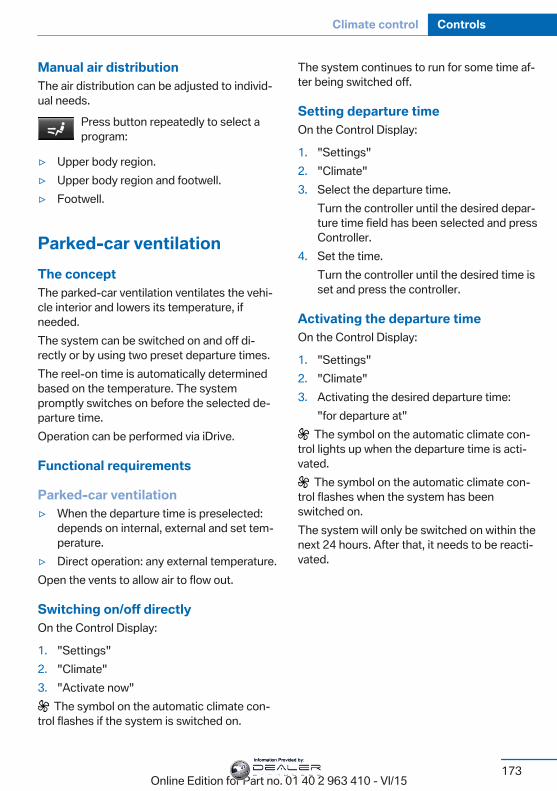
Manual air distributionThe air distribution can be adjusted to individ‐ual needs.
Press button repeatedly to select aprogram:
▷ Upper body region.▷ Upper body region and footwell.▷ Footwell.
Parked-car ventilationThe conceptThe parked-car ventilation ventilates the vehi‐cle interior and lowers its temperature, ifneeded.The system can be switched on and off di‐rectly or by using two preset departure times.The reel-on time is automatically determinedbased on the temperature. The systempromptly switches on before the selected de‐parture time.Operation can be performed via iDrive.
Functional requirements
Parked-car ventilation▷ When the departure time is preselected:
depends on internal, external and set tem‐perature.
▷ Direct operation: any external temperature.Open the vents to allow air to flow out.
Switching on/off directlyOn the Control Display:
1. "Settings"2. "Climate"3. "Activate now"
The symbol on the automatic climate con‐trol flashes if the system is switched on.
The system continues to run for some time af‐ter being switched off.
Setting departure timeOn the Control Display:
1. "Settings"2. "Climate"3. Select the departure time.
Turn the controller until the desired depar‐ture time field has been selected and pressController.
4. Set the time.Turn the controller until the desired time isset and press the controller.
Activating the departure timeOn the Control Display:
1. "Settings"2. "Climate"3. Activating the desired departure time:
"for departure at" The symbol on the automatic climate con‐
trol lights up when the departure time is acti‐vated.
The symbol on the automatic climate con‐trol flashes when the system has beenswitched on.The system will only be switched on within thenext 24 hours. After that, it needs to be reacti‐vated.
Seite 173
Climate control Controls
173Online Edition for Part no. 01 40 2 963 410 - VI/15
Information Provided by:
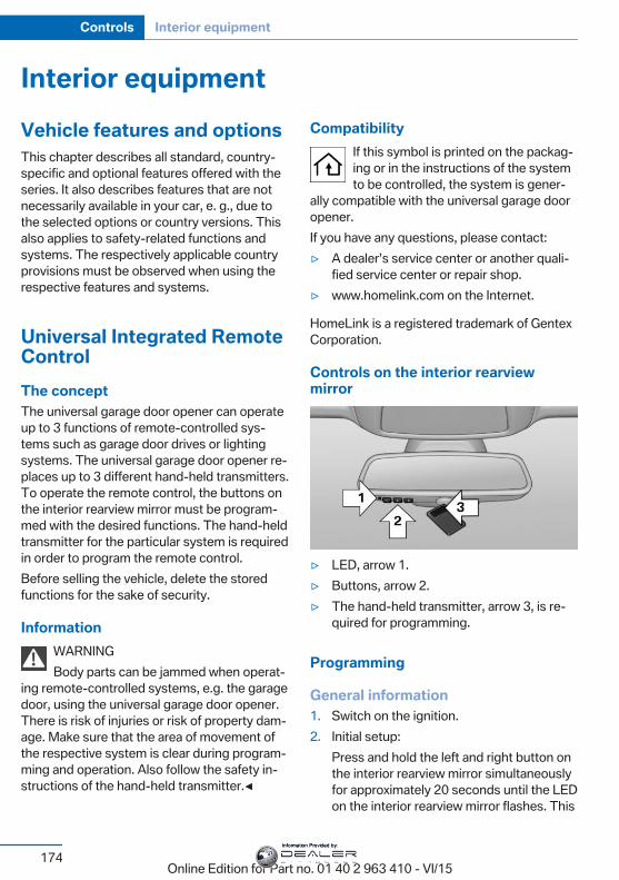
Interior equipmentVehicle features and optionsThis chapter describes all standard, country-specific and optional features offered with theseries. It also describes features that are notnecessarily available in your car, e. g., due tothe selected options or country versions. Thisalso applies to safety-related functions andsystems. The respectively applicable countryprovisions must be observed when using therespective features and systems.
Universal Integrated RemoteControlThe conceptThe universal garage door opener can operateup to 3 functions of remote-controlled sys‐tems such as garage door drives or lightingsystems. The universal garage door opener re‐places up to 3 different hand-held transmitters.To operate the remote control, the buttons onthe interior rearview mirror must be program‐med with the desired functions. The hand-heldtransmitter for the particular system is requiredin order to program the remote control.Before selling the vehicle, delete the storedfunctions for the sake of security.
InformationWARNINGBody parts can be jammed when operat‐
ing remote-controlled systems, e.g. the garagedoor, using the universal garage door opener.There is risk of injuries or risk of property dam‐age. Make sure that the area of movement ofthe respective system is clear during program‐ming and operation. Also follow the safety in‐structions of the hand-held transmitter.◀
CompatibilityIf this symbol is printed on the packag‐ing or in the instructions of the systemto be controlled, the system is gener‐
ally compatible with the universal garage dooropener.If you have any questions, please contact:▷ A dealer’s service center or another quali‐
fied service center or repair shop.▷ www.homelink.com on the Internet.
HomeLink is a registered trademark of GentexCorporation.
Controls on the interior rearviewmirror
▷ LED, arrow 1.▷ Buttons, arrow 2.▷ The hand-held transmitter, arrow 3, is re‐
quired for programming.
Programming
General information1. Switch on the ignition.2. Initial setup:
Press and hold the left and right button onthe interior rearview mirror simultaneouslyfor approximately 20 seconds until the LEDon the interior rearview mirror flashes. This
Seite 174
Controls Interior equipment
174Online Edition for Part no. 01 40 2 963 410 - VI/15
Information Provided by:
erases all programming of the buttons onthe interior rearview mirror.
3. Hold the hand-held transmitter for the sys‐tem to be controlled approx. 1 to 3 in/2.5 to8 cm away from the buttons of the interiorrearview mirror. The required distance de‐pends on the manual transmitter.
4. Simultaneously press and hold the buttonof the desired function on the hand-heldtransmitter and the button to be program‐med on the interior rearview mirror. TheLED on the interior rearview mirror will be‐gin flashing slowly.
5. Release both buttons as soon as the LEDflashes more rapidly. The LED flashingfaster indicates that the button on the inte‐rior rearview mirror has been programmed.If the LED does not flash faster after atleast 60 seconds, change the distance be‐tween the interior rearview mirror and thehand-held transmitter and repeat the step.Several more attempts at different distan‐ces may be necessary. Wait at least15 seconds between attempts.Canada: if programming with the hand-held transmitter was interrupted, holddown the interior rearview mirror buttonand repeatedly press and release thehand-held transmitter button for 2 sec‐onds.
6. To program other functions on other but‐tons, repeat steps 3 to 5.
The systems can be controlled using the inte‐rior rearview mirror buttons.
Special feature of the alternating-code wireless systemIf you are unable to operate the system afterrepeated programming, please check if thesystem to be controlled features an alternat‐ing-code system.Read the system's operating manual, or pressthe programmed button on the interior rear‐view mirror longer. If the LED on the interior
rearview mirror starts flashing rapidly and thenstays lit constantly for 2 seconds, the systemfeatures an alternating-code system. Flashingand continuous illumination of the LED will re‐peat for approximately 20 seconds.For systems with an alternating-code system,the universal garage door opener and the sys‐tem also have to be synchronized.Please read the operating manual to find outhow to synchronize the system.Synchronizing is easier with the aid of a sec‐ond person.To synchronize:
1. Park the vehicle within range of the re‐mote-controlled system.
2. Program the relevant button on the interiorrearview mirror as described.
3. Locate and press the synchronizing buttonon the system being programmed. Youhave approx. 30 seconds for the next step.
4. Hold down the programmed button on theinterior rearview mirror for approximately3 seconds and then release it. If necessary,repeat this step up to three times in orderto finish synchronization. Once synchroni‐zation is complete, the programmed func‐tion will be carried out.
Reprogramming individual buttons1. Switch on the ignition.2. Press and hold the interior rearview mirror
button to be programmed.3. As soon as the interior rearview mirror LED
starts flashing slowly, hold the hand-heldtransmitter for the system to be controlledapprox. 1 to 3 in/2.5 to 8 cm away from thebuttons of the interior rearview mirror. Therequired distance depends on the manualtransmitter.
Seite 175
Interior equipment Controls
175Online Edition for Part no. 01 40 2 963 410 - VI/15
Information Provided by:
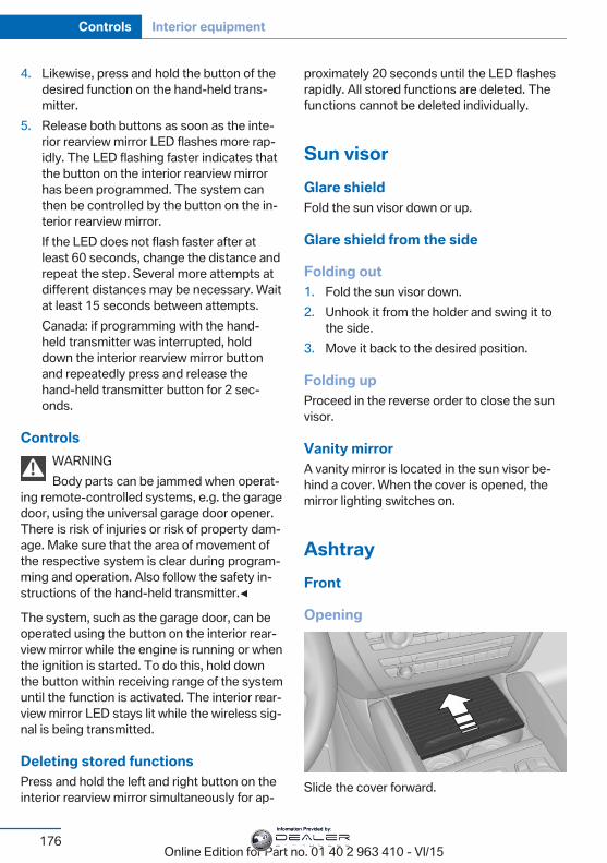
4. Likewise, press and hold the button of thedesired function on the hand-held trans‐mitter.
5. Release both buttons as soon as the inte‐rior rearview mirror LED flashes more rap‐idly. The LED flashing faster indicates thatthe button on the interior rearview mirrorhas been programmed. The system canthen be controlled by the button on the in‐terior rearview mirror.If the LED does not flash faster after atleast 60 seconds, change the distance andrepeat the step. Several more attempts atdifferent distances may be necessary. Waitat least 15 seconds between attempts.Canada: if programming with the hand-held transmitter was interrupted, holddown the interior rearview mirror buttonand repeatedly press and release thehand-held transmitter button for 2 sec‐onds.
ControlsWARNINGBody parts can be jammed when operat‐
ing remote-controlled systems, e.g. the garagedoor, using the universal garage door opener.There is risk of injuries or risk of property dam‐age. Make sure that the area of movement ofthe respective system is clear during program‐ming and operation. Also follow the safety in‐structions of the hand-held transmitter.◀
The system, such as the garage door, can beoperated using the button on the interior rear‐view mirror while the engine is running or whenthe ignition is started. To do this, hold downthe button within receiving range of the systemuntil the function is activated. The interior rear‐view mirror LED stays lit while the wireless sig‐nal is being transmitted.
Deleting stored functionsPress and hold the left and right button on theinterior rearview mirror simultaneously for ap‐
proximately 20 seconds until the LED flashesrapidly. All stored functions are deleted. Thefunctions cannot be deleted individually.
Sun visorGlare shieldFold the sun visor down or up.
Glare shield from the side
Folding out1. Fold the sun visor down.2. Unhook it from the holder and swing it to
the side.3. Move it back to the desired position.
Folding upProceed in the reverse order to close the sunvisor.
Vanity mirrorA vanity mirror is located in the sun visor be‐hind a cover. When the cover is opened, themirror lighting switches on.
AshtrayFront
Opening
Slide the cover forward.
Seite 176
Controls Interior equipment
176Online Edition for Part no. 01 40 2 963 410 - VI/15
Information Provided by:
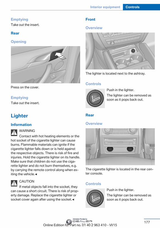
EmptyingTake out the insert.
Rear
Opening
Press on the cover.
EmptyingTake out the insert.
LighterInformation
WARNINGContact with hot heating elements or the
hot socket of the cigarette lighter can causeburns. Flammable materials can ignite if thecigarette lighter falls down or is held againstthe respective objects. There is risk of fire andinjuries. Hold the cigarette lighter on its handle.Make sure that children do not use the ciga‐rette lighter and do not burn themselves, e.g.by carrying the remote control along when ex‐iting the vehicle.◀
CAUTIONIf metal objects fall into the socket, they
can cause a short circuit. There is risk of prop‐erty damage. Replace the cigarette lighter orsocket cover again after using the socket.◀
Front
Overview
The lighter is located next to the ashtray.
ControlsPush in the lighter.The lighter can be removed assoon as it pops back out.
Rear
Overview
The cigarette lighter is located in the rear cen‐ter console.
ControlsPush in the lighter.The lighter can be removed assoon as it pops back out.
Seite 177
Interior equipment Controls
177Online Edition for Part no. 01 40 2 963 410 - VI/15
Information Provided by:
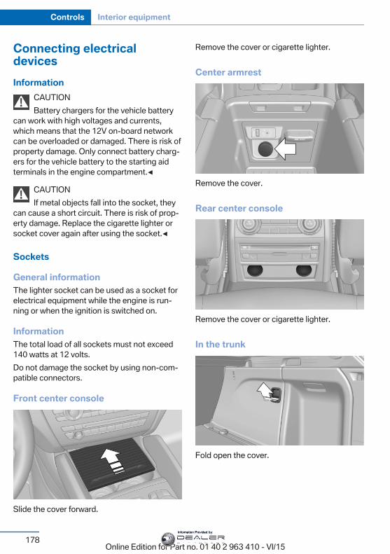
Connecting electricaldevicesInformation
CAUTIONBattery chargers for the vehicle battery
can work with high voltages and currents,which means that the 12V on-board networkcan be overloaded or damaged. There is risk ofproperty damage. Only connect battery charg‐ers for the vehicle battery to the starting aidterminals in the engine compartment.◀
CAUTIONIf metal objects fall into the socket, they
can cause a short circuit. There is risk of prop‐erty damage. Replace the cigarette lighter orsocket cover again after using the socket.◀
Sockets
General informationThe lighter socket can be used as a socket forelectrical equipment while the engine is run‐ning or when the ignition is switched on.
InformationThe total load of all sockets must not exceed140 watts at 12 volts.Do not damage the socket by using non-com‐patible connectors.
Front center console
Slide the cover forward.
Remove the cover or cigarette lighter.
Center armrest
Remove the cover.
Rear center console
Remove the cover or cigarette lighter.
In the trunk
Fold open the cover.
Seite 178
Controls Interior equipment
178Online Edition for Part no. 01 40 2 963 410 - VI/15
Information Provided by:
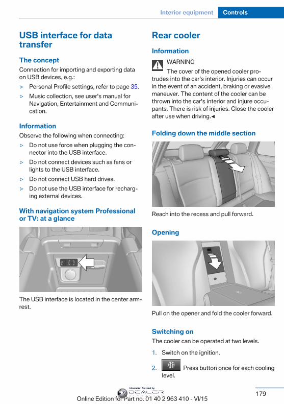
USB interface for datatransferThe conceptConnection for importing and exporting dataon USB devices, e.g.:▷ Personal Profile settings, refer to page 35.▷ Music collection, see user's manual for
Navigation, Entertainment and Communi‐cation.
InformationObserve the following when connecting:▷ Do not use force when plugging the con‐
nector into the USB interface.▷ Do not connect devices such as fans or
lights to the USB interface.▷ Do not connect USB hard drives.▷ Do not use the USB interface for recharg‐
ing external devices.
With navigation system Professionalor TV: at a glance
The USB interface is located in the center arm‐rest.
Rear coolerInformation
WARNINGThe cover of the opened cooler pro‐
trudes into the car's interior. Injuries can occurin the event of an accident, braking or evasivemaneuver. The content of the cooler can bethrown into the car's interior and injure occu‐pants. There is risk of injuries. Close the coolerafter use when driving.◀
Folding down the middle section
Reach into the recess and pull forward.
Opening
Pull on the opener and fold the cooler forward.
Switching onThe cooler can be operated at two levels.
1. Switch on the ignition.
2. Press button once for each coolinglevel.
Seite 179
Interior equipment Controls
179Online Edition for Part no. 01 40 2 963 410 - VI/15
Information Provided by:
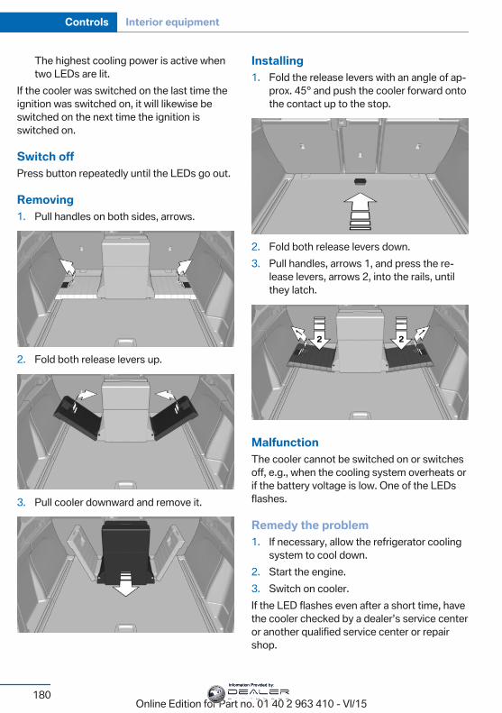
The highest cooling power is active whentwo LEDs are lit.
If the cooler was switched on the last time theignition was switched on, it will likewise beswitched on the next time the ignition isswitched on.
Switch offPress button repeatedly until the LEDs go out.
Removing1. Pull handles on both sides, arrows.
2. Fold both release levers up.
3. Pull cooler downward and remove it.
Installing1. Fold the release levers with an angle of ap‐
prox. 45° and push the cooler forward ontothe contact up to the stop.
2. Fold both release levers down.3. Pull handles, arrows 1, and press the re‐
lease levers, arrows 2, into the rails, untilthey latch.
MalfunctionThe cooler cannot be switched on or switchesoff, e.g., when the cooling system overheats orif the battery voltage is low. One of the LEDsflashes.
Remedy the problem1. If necessary, allow the refrigerator cooling
system to cool down.2. Start the engine.3. Switch on cooler.If the LED flashes even after a short time, havethe cooler checked by a dealer’s service centeror another qualified service center or repairshop.
Seite 180
Controls Interior equipment
180Online Edition for Part no. 01 40 2 963 410 - VI/15
Information Provided by:
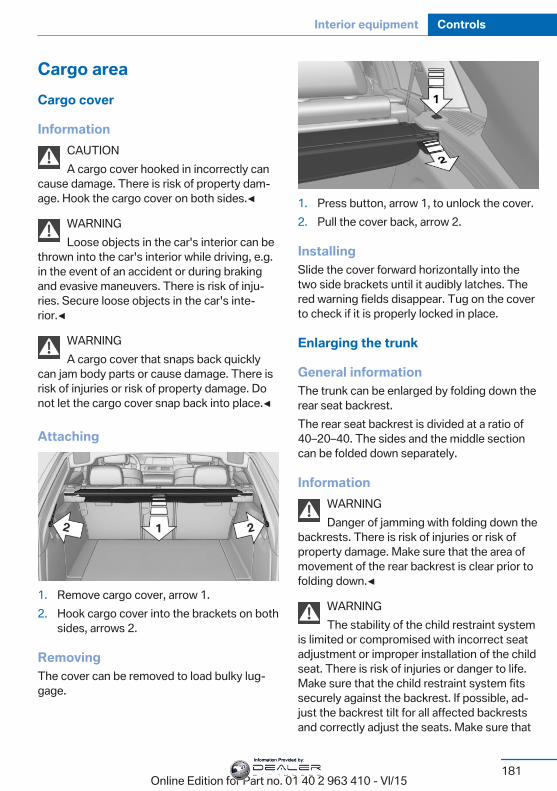
Cargo areaCargo cover
InformationCAUTIONA cargo cover hooked in incorrectly can
cause damage. There is risk of property dam‐age. Hook the cargo cover on both sides.◀
WARNINGLoose objects in the car's interior can be
thrown into the car's interior while driving, e.g.in the event of an accident or during brakingand evasive maneuvers. There is risk of inju‐ries. Secure loose objects in the car's inte‐rior.◀
WARNINGA cargo cover that snaps back quickly
can jam body parts or cause damage. There isrisk of injuries or risk of property damage. Donot let the cargo cover snap back into place.◀
Attaching
1. Remove cargo cover, arrow 1.2. Hook cargo cover into the brackets on both
sides, arrows 2.
RemovingThe cover can be removed to load bulky lug‐gage.
1. Press button, arrow 1, to unlock the cover.2. Pull the cover back, arrow 2.
InstallingSlide the cover forward horizontally into thetwo side brackets until it audibly latches. Thered warning fields disappear. Tug on the coverto check if it is properly locked in place.
Enlarging the trunk
General informationThe trunk can be enlarged by folding down therear seat backrest.The rear seat backrest is divided at a ratio of40–20–40. The sides and the middle sectioncan be folded down separately.
InformationWARNINGDanger of jamming with folding down the
backrests. There is risk of injuries or risk ofproperty damage. Make sure that the area ofmovement of the rear backrest is clear prior tofolding down.◀
WARNINGThe stability of the child restraint system
is limited or compromised with incorrect seatadjustment or improper installation of the childseat. There is risk of injuries or danger to life.Make sure that the child restraint system fitssecurely against the backrest. If possible, ad‐just the backrest tilt for all affected backrestsand correctly adjust the seats. Make sure that
Seite 181
Interior equipment Controls
181Online Edition for Part no. 01 40 2 963 410 - VI/15
Information Provided by:
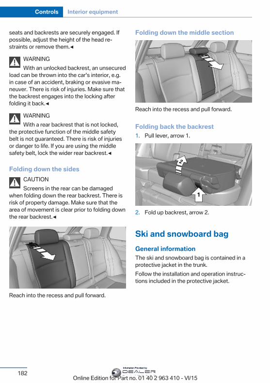
seats and backrests are securely engaged. Ifpossible, adjust the height of the head re‐straints or remove them.◀
WARNINGWith an unlocked backrest, an unsecured
load can be thrown into the car's interior, e.g.in case of an accident, braking or evasive ma‐neuver. There is risk of injuries. Make sure thatthe backrest engages into the locking afterfolding it back.◀
WARNINGWith a rear backrest that is not locked,
the protective function of the middle safetybelt is not guaranteed. There is risk of injuriesor danger to life. If you are using the middlesafety belt, lock the wider rear backrest.◀
Folding down the sidesCAUTIONScreens in the rear can be damaged
when folding down the rear backrest. There isrisk of property damage. Make sure that thearea of movement is clear prior to folding downthe rear backrest.◀
Reach into the recess and pull forward.
Folding down the middle section
Reach into the recess and pull forward.
Folding back the backrest1. Pull lever, arrow 1.
2. Fold up backrest, arrow 2.
Ski and snowboard bagGeneral informationThe ski and snowboard bag is contained in aprotective jacket in the trunk.Follow the installation and operation instruc‐tions included in the protective jacket.
Seite 182
Controls Interior equipment
182Online Edition for Part no. 01 40 2 963 410 - VI/15
Information Provided by:
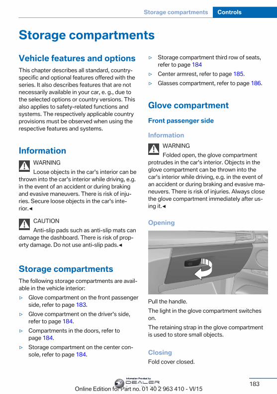
Storage compartmentsVehicle features and optionsThis chapter describes all standard, country-specific and optional features offered with theseries. It also describes features that are notnecessarily available in your car, e. g., due tothe selected options or country versions. Thisalso applies to safety-related functions andsystems. The respectively applicable countryprovisions must be observed when using therespective features and systems.
InformationWARNINGLoose objects in the car's interior can be
thrown into the car's interior while driving, e.g.in the event of an accident or during brakingand evasive maneuvers. There is risk of inju‐ries. Secure loose objects in the car's inte‐rior.◀
CAUTIONAnti-slip pads such as anti-slip mats can
damage the dashboard. There is risk of prop‐erty damage. Do not use anti-slip pads.◀
Storage compartmentsThe following storage compartments are avail‐able in the vehicle interior:▷ Glove compartment on the front passenger
side, refer to page 183.▷ Glove compartment on the driver's side,
refer to page 184.▷ Compartments in the doors, refer to
page 184.▷ Storage compartment on the center con‐
sole, refer to page 184.
▷ Storage compartment third row of seats,refer to page 184
▷ Center armrest, refer to page 185.▷ Glasses compartment, refer to page 186.
Glove compartmentFront passenger side
InformationWARNINGFolded open, the glove compartment
protrudes in the car's interior. Objects in theglove compartment can be thrown into thecar's interior while driving, e.g. in the event ofan accident or during braking and evasive ma‐neuvers. There is risk of injuries. Always closethe glove compartment immediately after us‐ing it.◀
Opening
Pull the handle.The light in the glove compartment switcheson.The retaining strap in the glove compartmentis used to store small objects.
ClosingFold cover closed.
Seite 183
Storage compartments Controls
183Online Edition for Part no. 01 40 2 963 410 - VI/15
Information Provided by:
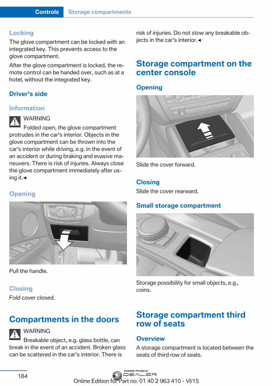
LockingThe glove compartment can be locked with anintegrated key. This prevents access to theglove compartment.After the glove compartment is locked, the re‐mote control can be handed over, such as at ahotel, without the integrated key.
Driver's side
InformationWARNINGFolded open, the glove compartment
protrudes in the car's interior. Objects in theglove compartment can be thrown into thecar's interior while driving, e.g. in the event ofan accident or during braking and evasive ma‐neuvers. There is risk of injuries. Always closethe glove compartment immediately after us‐ing it.◀
Opening
Pull the handle.
ClosingFold cover closed.
Compartments in the doorsWARNINGBreakable object, e.g. glass bottle, can
break in the event of an accident. Broken glasscan be scattered in the car's interior. There is
risk of injuries. Do not stow any breakable ob‐jects in the car's interior.◀
Storage compartment on thecenter consoleOpening
Slide the cover forward.
ClosingSlide the cover rearward.
Small storage compartment
Storage possibility for small objects, e.g.,coins.
Storage compartment thirdrow of seatsOverviewA storage compartment is located between theseats of third row of seats.
Seite 184
Controls Storage compartments
184Online Edition for Part no. 01 40 2 963 410 - VI/15
Information Provided by:
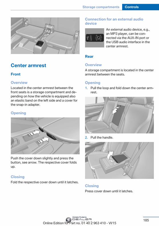
Center armrestFront
OverviewLocated in the center armrest between thefront seats is a storage compartment and de‐pending on how the vehicle is equipped alsoan elastic band on the left side and a cover forthe snap-in adapter.
Opening
Push the cover down slightly and press thebutton, see arrow. The respective cover foldsup.
ClosingFold the respective cover down until it latches.
Connection for an external audiodevice
An external audio device, e.g.,an MP3 player, can be con‐nected via the AUX-IN port orthe USB audio interface in thecenter armrest.
Rear
OverviewA storage compartment is located in the centerarmrest between the seats.
Opening1. Pull the loop and fold down the center arm‐
rest.
2. Pull the handle.
ClosingPress cover down until it latches.
Seite 185
Storage compartments Controls
185Online Edition for Part no. 01 40 2 963 410 - VI/15
Information Provided by:
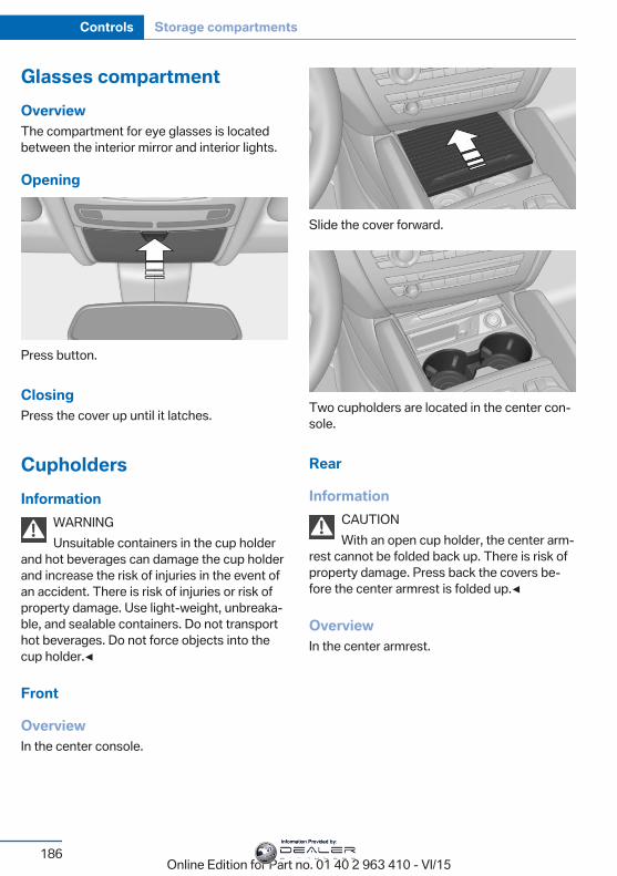
Glasses compartmentOverviewThe compartment for eye glasses is locatedbetween the interior mirror and interior lights.
Opening
Press button.
ClosingPress the cover up until it latches.
CupholdersInformation
WARNINGUnsuitable containers in the cup holder
and hot beverages can damage the cup holderand increase the risk of injuries in the event ofan accident. There is risk of injuries or risk ofproperty damage. Use light-weight, unbreaka‐ble, and sealable containers. Do not transporthot beverages. Do not force objects into thecup holder.◀
Front
OverviewIn the center console.
Slide the cover forward.
Two cupholders are located in the center con‐sole.
Rear
InformationCAUTIONWith an open cup holder, the center arm‐
rest cannot be folded back up. There is risk ofproperty damage. Press back the covers be‐fore the center armrest is folded up.◀
OverviewIn the center armrest.
Seite 186
Controls Storage compartments
186Online Edition for Part no. 01 40 2 963 410 - VI/15
Information Provided by:
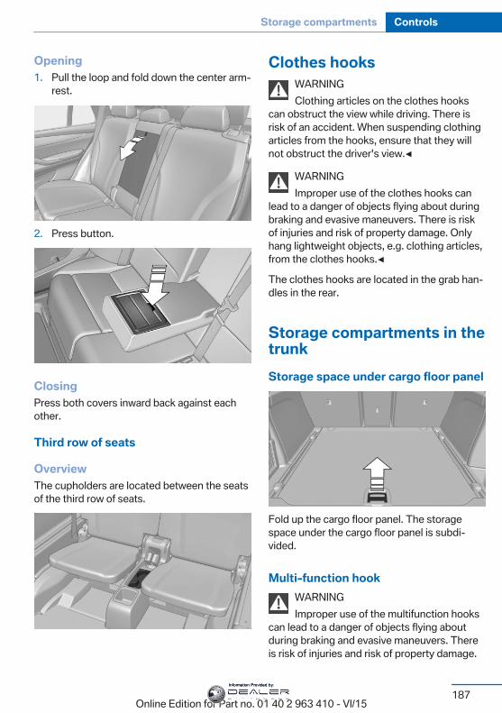
Opening1. Pull the loop and fold down the center arm‐
rest.
2. Press button.
ClosingPress both covers inward back against eachother.
Third row of seats
OverviewThe cupholders are located between the seatsof the third row of seats.
Clothes hooksWARNINGClothing articles on the clothes hooks
can obstruct the view while driving. There isrisk of an accident. When suspending clothingarticles from the hooks, ensure that they willnot obstruct the driver's view.◀
WARNINGImproper use of the clothes hooks can
lead to a danger of objects flying about duringbraking and evasive maneuvers. There is riskof injuries and risk of property damage. Onlyhang lightweight objects, e.g. clothing articles,from the clothes hooks.◀
The clothes hooks are located in the grab han‐dles in the rear.
Storage compartments in thetrunkStorage space under cargo floor panel
Fold up the cargo floor panel. The storagespace under the cargo floor panel is subdi‐vided.
Multi-function hookWARNINGImproper use of the multifunction hooks
can lead to a danger of objects flying aboutduring braking and evasive maneuvers. Thereis risk of injuries and risk of property damage.
Seite 187
Storage compartments Controls
187Online Edition for Part no. 01 40 2 963 410 - VI/15
Information Provided by:
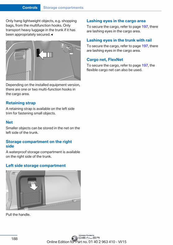
Only hang lightweight objects, e.g. shoppingbags, from the multifunction hooks. Onlytransport heavy luggage in the trunk if it hasbeen appropriately secured.◀
Depending on the installed equipment version,there are one or two multi-function hooks inthe cargo area.
Retaining strapA retaining strap is available on the left sidetrim for fastening small objects.
NetSmaller objects can be stored in the net on theleft side of the trunk.
Storage compartment on the rightsideA waterproof storage compartment is availableon the right side of the trunk.
Left side storage compartment
Pull the handle.
Lashing eyes in the cargo areaTo secure the cargo, refer to page 197, thereare lashing eyes in the cargo area.
Lashing eyes in the trunk with railTo secure the cargo, refer to page 197, thereare lashing eyes in the cargo area.
Cargo net, FlexNetTo secure the cargo, refer to page 197, theflexible cargo net can also be used.
Seite 188
Controls Storage compartments
188Online Edition for Part no. 01 40 2 963 410 - VI/15
Information Provided by:

Seite 189
Storage compartments Controls
189Online Edition for Part no. 01 40 2 963 410 - VI/15
Information Provided by:
Online Edition for Part no. 01 40 2 963 410 - VI/15
Information Provided by:
Driving tipsThis chapter provides you with information
useful in dealing with specific driving andoperating modes.
Online Edition for Part no. 01 40 2 963 410 - VI/15
Information Provided by:
Things to remember when drivingVehicle features and optionsThis chapter describes all standard, country-specific and optional features offered with theseries. It also describes features that are notnecessarily available in your car, e. g., due tothe selected options or country versions. Thisalso applies to safety-related functions andsystems. The respectively applicable countryprovisions must be observed when using therespective features and systems.
Breaking-in periodGeneral informationMoving parts need time to adjust to one an‐other (break-in time).The following instructions will help accomplisha long vehicle life and good efficiency.During break-in, do not use the Launch Con‐trol, refer to page 83.
Engine, transmission, and axle drive
Up to 1,200 miles/2,000 kmDo not exceed the maximum engine and roadspeed:▷ For gasoline engine 4,500 rpm and
100 mph/160 km/h.▷ For diesel engine 3,500 rpm and
93 mph/150 km/h.Avoid full load or kickdown under all circum‐stances.
From 1,200 miles/2,000 kmThe engine and vehicle speed can gradually beincreased.
TiresTire traction is not optimal due to manufactur‐ing circumstances when tires are brand-new;they achieve their full traction potential after abreak-in time.Drive conservatively for the first200 miles/300 km.
Brake systemBrakes require an initial break-in period of ap‐prox. 300 miles/500 km to achieve optimal per‐formance between brake discs and brakepads. Drive moderately during this break-in pe‐riod.
Following part replacementThe same break-in procedures should be ob‐served if any of the components above-men‐tioned have to be renewed in the course of thevehicle's operating life.
General driving notesClosing the tailgate
WARNINGAn open tailgate protrudes from the vehi‐
cle and can endanger occupants and othertraffic participants or damage the vehicle in theevent of an accident, braking or evasive ma‐neuvers. In addition, exhaust fumes may enterthe vehicle interior. There is risk of injuries orrisk of property damage. Do not drive with thetailgate open.◀
If driving with the tailgate open cannot beavoided:▷ Close all windows and the glass sunroof.▷ Greatly increase the air flow from the vents.▷ Drive moderately.
Seite 192
Driving tips Things to remember when driving
192Online Edition for Part no. 01 40 2 963 410 - VI/15
Information Provided by:
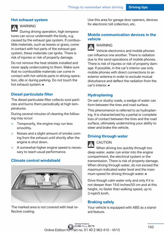
Hot exhaust systemWARNINGDuring driving operation, high tempera‐
tures can occur underneath the body, e.g.caused by the exhaust gas system. If combus‐tible materials, such as leaves or grass, comein contact with hot parts of the exhaust gassystem, these materials can ignite. There isrisk of injuries or risk of property damage.Do not remove the heat shields installed andnever apply undercoating to them. Make surethat no combustible materials can come incontact with hot vehicle parts in driving opera‐tion, idle or during parking. Do not touch thehot exhaust system.◀
Diesel particulate filterThe diesel particulate filter collects soot parti‐cles and burns them periodically at high tem‐peratures.During several minutes of cleaning the follow‐ing may occur:▷ Temporarily, the engine may run less
smoothly.▷ Noises and a slight amount of smoke com‐
ing from the exhaust until shortly after theengine is shut down.
▷ A somewhat higher engine speed is neces‐sary to reach usual performance.
Climate control windshield
The marked area is not covered with heat re‐flective coating.
Use this area for garage door openers, devicesfor electronic toll collection, etc.
Mobile communication devices in thevehicle
WARNINGVehicle electronics and mobile phones
can influence one another. There is radiationdue to the send operations of mobile phones.There is risk of injuries or risk of property dam‐age. If possible, in the car's interior use onlymobile phones with direct connections to anexterior antenna in order to exclude mutualdisturbance and deflect the radiation from thecar's interior.◀
HydroplaningOn wet or slushy roads, a wedge of water canform between the tires and road surface.This phenomenon is referred to as hydroplan‐ing. It is characterized by a partial or completeloss of contact between the tires and the roadsurface, ultimately undermining your ability tosteer and brake the vehicle.
Driving through waterCAUTIONWhen driving too quickly through too
deep water, water can enter into the enginecompartment, the electrical system or thetransmission. There is risk of property damage.When driving through water, do not exceed themaximum indicated water level and the maxi‐mum speed for driving through water.◀
Drive though calm water only and only if it isnot deeper than 19.6 inches/50 cm and at thisheight, no faster than walking speed, up to3 mph/5 km/h.
Braking safelyYour vehicle is equipped with ABS as a stand‐ard feature.
Seite 193
Things to remember when driving Driving tips
193Online Edition for Part no. 01 40 2 963 410 - VI/15
Information Provided by:
Applying the brakes fully is the most effectiveway of braking in situations needed.Steering is still responsive. You can still avoidany obstacles with a minimum of steering ef‐fort.Pulsation of the brake pedal and sounds fromthe hydraulic circuits indicate that ABS is in itsactive mode.In certain braking situations, the perforatedbrake discs can cause functional problems.However, this has no effect on the perform‐ance and operational reliability of the brake.
Objects in the movement area aroundpedals and floor area
WARNINGObjects in the driver's floor area can limit
the pedal distance or block a depressed pedal.There is risk of an accident. Stow objects inthe vehicle such that they are secured andcannot enter into the driver's floor area. Usefloor mats that are suitable for the vehicle andcan be safely attached to the floor. Do not useloose floor mats and do not layer several floormats. Make sure that there is sufficient clear‐ance for the pedals. Ensure that the floor matsare securely fastened again after they were re‐moved, e.g. for cleaning.◀
Driving in wet conditionsWhen roads are wet, salted, or in heavy rain,press brake pedal ever so gently every fewmiles.Ensure that this action does not endangerother traffic.The heat generated in this process helps drythe brake discs and pads.In this way braking efficiency will be availablewhen you need it.
HillsWARNINGLight but consistent brake pressure can
lead to high temperatures, brakes wearing outand possibly even brake failure. There is risk ofan accident. Avoid placing excessive stress onthe brake system.◀
WARNINGIn idle or with the engine switched off,
safety-relevant functions are restricted or notavailable anymore, e.g. braking effect of theengine or braking force and steering support.There is risk of an accident. Do not drive in idleor with the engine switched off.◀
Drive long or steep downhill gradients in thegear that requires least braking efforts. Other‐wise the brakes may overheat and reducebrake efficiency.You can increase the engine's braking effectby shifting down, going all the way to first gear,if needed.
Brake disc corrosionCorrosion on the brake discs and contamina‐tion on the brake pads are furthered by the fol‐lowing circumstances:▷ Low mileage.▷ Extended periods when the vehicle is not
used at all.▷ Infrequent use of the brakes.Corrosion will built up when the maximumpressure applied to the brake pads duringbraking is not reached - thus discs don't getcleaned.Corrosion buildup on the brake discs will causea pulsating effect on the brakes in their re‐sponse - generally that cannot be corrected.
Seite 194
Driving tips Things to remember when driving
194Online Edition for Part no. 01 40 2 963 410 - VI/15
Information Provided by:
Condensation under the parkedvehicleWhen using the automatic climate control,condensation water develops collecting under‐neath the vehicle.These traces of water under the vehicle arenormal.
Driving on poor roadsThe vehicle combines all-wheel drive with theadvantages of a normal automobile.
CAUTIONObjects in unpaved areas, e.g. stones or
branches, can damage the vehicle. There isrisk of property damage. Do not drive on un‐paved terrain.◀
For your own safety, for the safety of passen‐gers and of the vehicle, heed the followingpoints:▷ Become familiar with the vehicle before
starting a trip; do not take risks in driving.▷ Adjust the speed to the road surface con‐
ditions. The steeper and more uneven theroad surface, the slower the speed shouldbe.
▷ When driving on steep uphill or downhillgrades: add engine oil and coolant up tonear the MAX mark. Uphill and downhillgrades can be traveled up to no more than50 %.
▷ On steep downhill grades, use Hill DescentControl HDC, refer to page 140.Starting out is possible on uphill grades upto 32 %. The permissible side tilt is 50 %.
▷ Avoid that the chassis bottom coming incontact with the ground.The ground clearance is no more than 7.8inches/20 cm and can vary according tothe vehicle's load.
▷ When wheels continue to spin, depress theaccelerator so that driving stability control
systems can distribute the driving force tothe wheels. Activate DTC Dynamic Trac‐tion Control if available.
After a trip on poor roadsAfter a trip on poor roads, check wheels andtires for damage to maintain driving safety.Clear heavy soiling from the body.
Seite 195
Things to remember when driving Driving tips
195Online Edition for Part no. 01 40 2 963 410 - VI/15
Information Provided by:
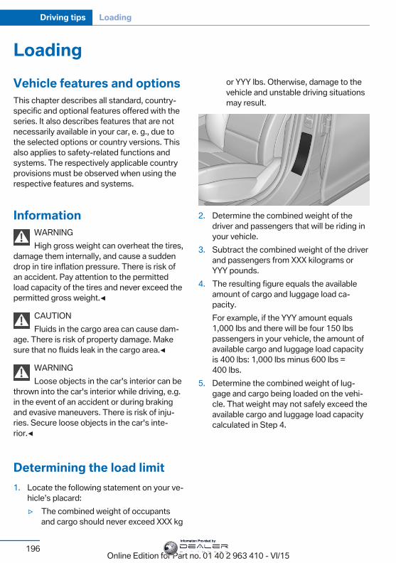
LoadingVehicle features and optionsThis chapter describes all standard, country-specific and optional features offered with theseries. It also describes features that are notnecessarily available in your car, e. g., due tothe selected options or country versions. Thisalso applies to safety-related functions andsystems. The respectively applicable countryprovisions must be observed when using therespective features and systems.
InformationWARNINGHigh gross weight can overheat the tires,
damage them internally, and cause a suddendrop in tire inflation pressure. There is risk ofan accident. Pay attention to the permittedload capacity of the tires and never exceed thepermitted gross weight.◀
CAUTIONFluids in the cargo area can cause dam‐
age. There is risk of property damage. Makesure that no fluids leak in the cargo area.◀
WARNINGLoose objects in the car's interior can be
thrown into the car's interior while driving, e.g.in the event of an accident or during brakingand evasive maneuvers. There is risk of inju‐ries. Secure loose objects in the car's inte‐rior.◀
Determining the load limit1. Locate the following statement on your ve‐
hicle’s placard:▷ The combined weight of occupants
and cargo should never exceed XXX kg
or YYY lbs. Otherwise, damage to thevehicle and unstable driving situationsmay result.
2. Determine the combined weight of thedriver and passengers that will be riding inyour vehicle.
3. Subtract the combined weight of the driverand passengers from XXX kilograms orYYY pounds.
4. The resulting figure equals the availableamount of cargo and luggage load ca‐pacity.For example, if the YYY amount equals1,000 lbs and there will be four 150 lbspassengers in your vehicle, the amount ofavailable cargo and luggage load capacityis 400 lbs: 1,000 lbs minus 600 lbs =400 lbs.
5. Determine the combined weight of lug‐gage and cargo being loaded on the vehi‐cle. That weight may not safely exceed theavailable cargo and luggage load capacitycalculated in Step 4.
Seite 196
Driving tips Loading
196Online Edition for Part no. 01 40 2 963 410 - VI/15
Information Provided by:
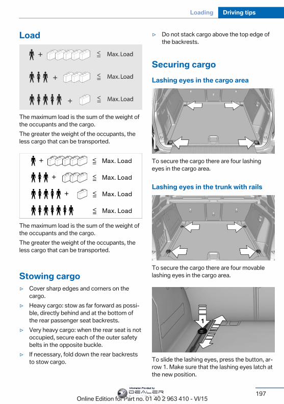
Load
The maximum load is the sum of the weight ofthe occupants and the cargo.The greater the weight of the occupants, theless cargo that can be transported.
The maximum load is the sum of the weight ofthe occupants and the cargo.The greater the weight of the occupants, theless cargo that can be transported.
Stowing cargo▷ Cover sharp edges and corners on the
cargo.▷ Heavy cargo: stow as far forward as possi‐
ble, directly behind and at the bottom ofthe rear passenger seat backrests.
▷ Very heavy cargo: when the rear seat is notoccupied, secure each of the outer safetybelts in the opposite buckle.
▷ If necessary, fold down the rear backreststo stow cargo.
▷ Do not stack cargo above the top edge ofthe backrests.
Securing cargoLashing eyes in the cargo area
To secure the cargo there are four lashingeyes in the cargo area.
Lashing eyes in the trunk with rails
To secure the cargo there are four movablelashing eyes in the cargo area.
To slide the lashing eyes, press the button, ar‐row 1. Make sure that the lashing eyes latch atthe new position.
Seite 197
Loading Driving tips
197Online Edition for Part no. 01 40 2 963 410 - VI/15
Information Provided by:
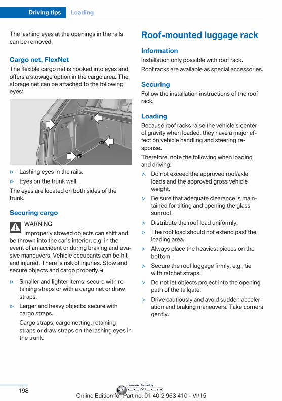
The lashing eyes at the openings in the railscan be removed.
Cargo net, FlexNetThe flexible cargo net is hooked into eyes andoffers a stowage option in the cargo area. Thestorage net can be attached to the followingeyes:
▷ Lashing eyes in the rails.▷ Eyes on the trunk wall.The eyes are located on both sides of thetrunk.
Securing cargoWARNINGImproperly stowed objects can shift and
be thrown into the car's interior, e.g. in theevent of an accident or during braking and eva‐sive maneuvers. Vehicle occupants can be hitand injured. There is risk of injuries. Stow andsecure objects and cargo properly.◀
▷ Smaller and lighter items: secure with re‐taining straps or with a cargo net or drawstraps.
▷ Larger and heavy objects: secure withcargo straps.Cargo straps, cargo netting, retainingstraps or draw straps on the lashing eyes inthe trunk.
Roof-mounted luggage rackInformationInstallation only possible with roof rack.Roof racks are available as special accessories.
SecuringFollow the installation instructions of the roofrack.
LoadingBecause roof racks raise the vehicle's centerof gravity when loaded, they have a major ef‐fect on vehicle handling and steering re‐sponse.Therefore, note the following when loadingand driving:▷ Do not exceed the approved roof/axle
loads and the approved gross vehicleweight.
▷ Be sure that adequate clearance is main‐tained for tilting and opening the glasssunroof.
▷ Distribute the roof load uniformly.▷ The roof load should not extend past the
loading area.▷ Always place the heaviest pieces on the
bottom.▷ Secure the roof luggage firmly, e.g., tie
with ratchet straps.▷ Do not let objects project into the opening
path of the tailgate.▷ Drive cautiously and avoid sudden acceler‐
ation and braking maneuvers. Take cornersgently.
Seite 198
Driving tips Loading
198Online Edition for Part no. 01 40 2 963 410 - VI/15
Information Provided by:
Saving fuelVehicle features and optionsThis chapter describes all standard, country-specific and optional features offered with theseries. It also describes features that are notnecessarily available in your car, e. g., due tothe selected options or country versions. Thisalso applies to safety-related functions andsystems. The respectively applicable countryprovisions must be observed when using therespective features and systems.
General informationYour vehicle contains advanced technology forthe reduction of fuel consumption and emis‐sions.Fuel consumption depends on a number of dif‐ferent factors.Carrying out certain measures, such as a mod‐erate driving style and regular maintenance,can influence fuel consumption and the envi‐ronmental impact.
Remove unnecessary cargoAdditional weight increases fuel consumption.
Remove attached partsfollowing useRemove auxiliary mirrors, roof or rear luggageracks which are no longer required followinguse.Attached parts on the vehicle impair the aero‐dynamics and increase the fuel consumption.
Close the windows and glasssunroofDriving with the glass sunroof and windowsopen results in increased air resistance andthereby reduces the range.
TiresGeneral informationTires can affect fuel consumption in variousways, e.g., tire size may influence fuel con‐sumption.
Check the tire inflation pressureregularlyCheck and, if needed, correct the tire inflationpressure at least twice a month and beforestarting on a long trip.Low tire inflation pressure increases rolling re‐sistance and thus raises fuel consumption andtire wear.
Drive away immediatelyDo not wait for the engine to warm-up whilethe vehicle remains stationary. Start drivingright away, but at moderate engine speeds.This is the quickest way of warming the coldengine up to operating temperature.
Look well ahead whendrivingAvoid unnecessary acceleration and braking.By maintaining a suitable distance to the vehi‐cle driving ahead of you.Driving smoothly and proactively reduces fuelconsumption.
Seite 199
Saving fuel Driving tips
199Online Edition for Part no. 01 40 2 963 410 - VI/15
Information Provided by:
Avoid high engine speedsAs a rule: driving at low engine speeds lowersfuel consumption and reduces wear.If necessary, observe the gear shift indicator ofthe vehicle, refer to page 96.
Use coastingWhen approaching a red light, take your footoff the accelerator and let the vehicle coast toa halt.For going downhill take your foot off the accel‐erator and let the vehicle roll.The flow of fuel is interrupted while coasting.
Switch off the engine duringlonger stopsSwitch off the engine during longer stops, e.g.,at traffic lights, railroad crossings or in trafficcongestion.
Auto Start/Stop functionThe Auto Start/Stop function of your vehicleautomatically switches off the engine during astop.If the engine is switched off and then restartedrather than leaving the engine running con‐stantly, fuel consumption and emissions arereduced. Savings can begin within a few sec‐onds of switching off the engine.In addition, fuel consumption is also deter‐mined by other factors, such as driving style,road conditions, maintenance or environmentalfactors.
Switch off any functions thatare not currently neededFunctions such as seat heating and the rearwindow defroster require a lot of energy and
reduce the range, especially in city and stop-and-go traffic.Switch off these functions if they are notneeded.The ECO PRO driving program supports theenergy conserving use of comfort features.These functions are automatically deactivatedpartially or completely.
Have maintenance carriedoutHave vehicles maintained regularly to achieveoptimal vehicle efficiency and service life.BMW recommends that maintenance work beperformed by a BMW dealer’s service center.For information on the BMW MaintenanceSystem, refer to page 238.
ECO PROThe conceptECO PRO supports a driving style that saveson fuel consumption. For this purpose, the en‐gine control and comfort features, e. g. the cli‐mate control output, are adjusted.Under certain conditions the engine is auto‐matically decoupled from the transmission inthe D selector lever position. The vehicle con‐tinues traveling with the engine idling to re‐duce fuel consumption. Selector lever positionD remains engaged.In addition, context-sensitive instructions aredisplayed to assist with an optimized fuel con‐sumption driving style.The achieved extended range is displayed inthe instrument cluster as bonus range.
OverviewThe system includes the followingEfficientDynamics functions and displays:▷ ECO PRO bonus range, refer to page 201.
Seite 200
Driving tips Saving fuel
200Online Edition for Part no. 01 40 2 963 410 - VI/15
Information Provided by:
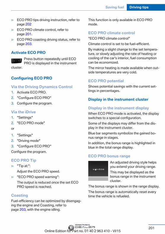
▷ ECO PRO tips driving instruction, refer topage 202
▷ ECO PRO climate control, refer topage 201.
▷ ECO PRO coasting driving status, refer topage 203.
Activate ECO PROPress button repeatedly until ECOPRO is displayed in the instrument
cluster.
Configuring ECO PRO
Via the Driving Dynamics Control1. Activate ECO PRO.2. "Configure ECO PRO"3. Configure the program.
Via the iDrive1. "Settings"2. "ECO PRO mode"or
1. "Settings"2. "Driving mode"3. "Configure ECO PRO"Configure the program.
ECO PRO Tip▷ "Tip at:":
Adjust the ECO PRO speed.▷ "ECO PRO speed warning":
The output is reduced once the set ECOPRO speed is reached.
CoastingFuel-efficiency can be optimized by disengag‐ing the engine and Coasting, refer topage 203, with the engine idling.
This function is only available in ECO PROmode.
ECO PRO climate control"ECO PRO climate control"Climate control is set to be fuel-efficient.By making a slight change to the set tempera‐ture, or slowly adjusting the rate of heating orcooling of the car's interior, fuel consumptioncan be economized.The mirror heating is made available when out‐side temperatures are very cold.
ECO PRO potentialShows potential savings with the current set‐tings in percentages.
Display in the instrument cluster
Display in the instrument displayWhen ECO PRO mode is activated, the displayswitches to a special configuration.Some of the displays may differ from the dis‐play in the instrument cluster.Blue bar segments symbolize the gained bo‐nus range in stages.In addition, the bonus range is highlighted inblue in the total range display.
ECO PRO bonus rangeAn adjusted driving style helpsyou extend your driving range.This may be displayed as thebonus range in the instrumentcluster.
The bonus range is shown in the range display.The bonus range is automatically reset everytime the vehicle is refueled.
Seite 201
Saving fuel Driving tips
201Online Edition for Part no. 01 40 2 963 410 - VI/15
Information Provided by:
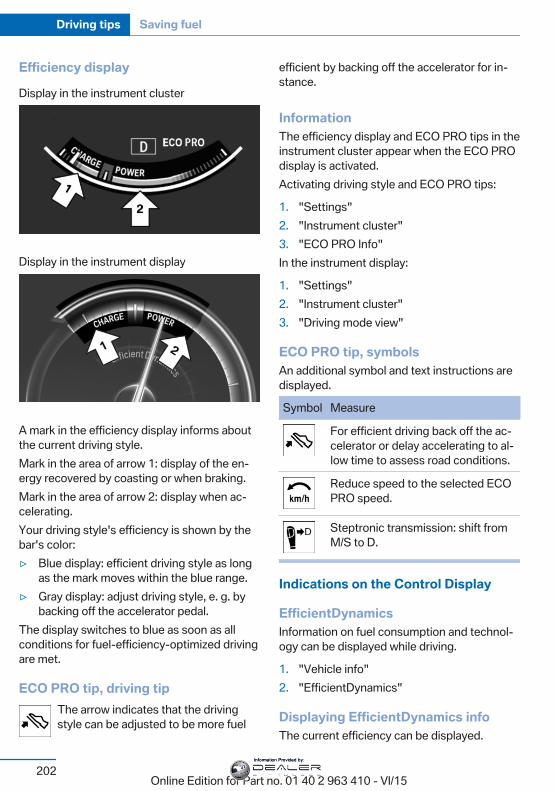
Efficiency displayDisplay in the instrument cluster
Display in the instrument display
A mark in the efficiency display informs aboutthe current driving style.Mark in the area of arrow 1: display of the en‐ergy recovered by coasting or when braking.Mark in the area of arrow 2: display when ac‐celerating.Your driving style's efficiency is shown by thebar's color:▷ Blue display: efficient driving style as long
as the mark moves within the blue range.▷ Gray display: adjust driving style, e. g. by
backing off the accelerator pedal.The display switches to blue as soon as allconditions for fuel-efficiency-optimized drivingare met.
ECO PRO tip, driving tipThe arrow indicates that the drivingstyle can be adjusted to be more fuel
efficient by backing off the accelerator for in‐stance.
InformationThe efficiency display and ECO PRO tips in theinstrument cluster appear when the ECO PROdisplay is activated.Activating driving style and ECO PRO tips:
1. "Settings"2. "Instrument cluster"3. "ECO PRO Info"In the instrument display:
1. "Settings"2. "Instrument cluster"3. "Driving mode view"
ECO PRO tip, symbolsAn additional symbol and text instructions aredisplayed.
Symbol Measure
For efficient driving back off the ac‐celerator or delay accelerating to al‐low time to assess road conditions.
Reduce speed to the selected ECOPRO speed.
Steptronic transmission: shift fromM/S to D.
Indications on the Control Display
EfficientDynamicsInformation on fuel consumption and technol‐ogy can be displayed while driving.
1. "Vehicle info"2. "EfficientDynamics"
Displaying EfficientDynamics infoThe current efficiency can be displayed.
Seite 202
Driving tips Saving fuel
202Online Edition for Part no. 01 40 2 963 410 - VI/15
Information Provided by:
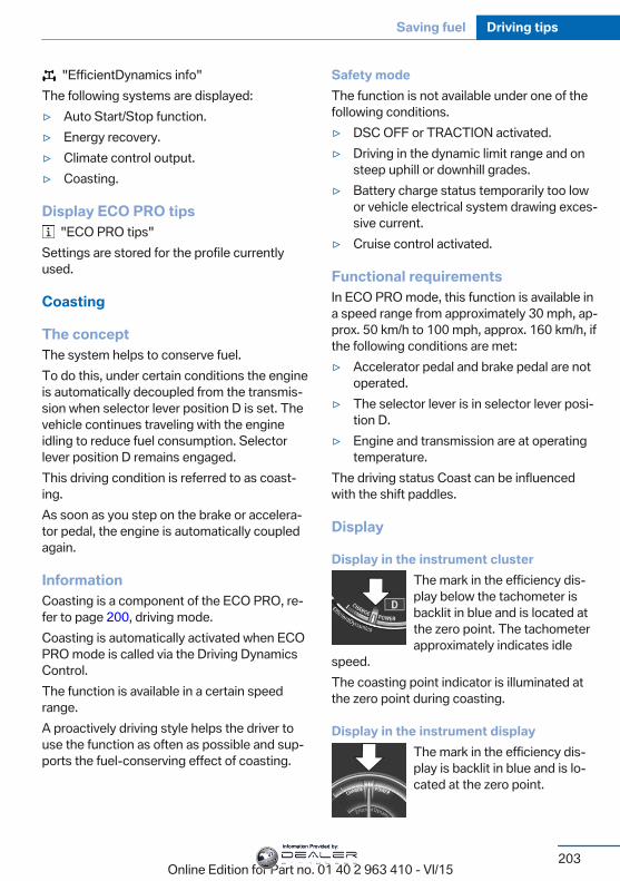
"EfficientDynamics info"The following systems are displayed:▷ Auto Start/Stop function.▷ Energy recovery.▷ Climate control output.▷ Coasting.
Display ECO PRO tips "ECO PRO tips"
Settings are stored for the profile currentlyused.
Coasting
The conceptThe system helps to conserve fuel.To do this, under certain conditions the engineis automatically decoupled from the transmis‐sion when selector lever position D is set. Thevehicle continues traveling with the engineidling to reduce fuel consumption. Selectorlever position D remains engaged.This driving condition is referred to as coast‐ing.As soon as you step on the brake or accelera‐tor pedal, the engine is automatically coupledagain.
InformationCoasting is a component of the ECO PRO, re‐fer to page 200, driving mode.Coasting is automatically activated when ECOPRO mode is called via the Driving DynamicsControl.The function is available in a certain speedrange.A proactively driving style helps the driver touse the function as often as possible and sup‐ports the fuel-conserving effect of coasting.
Safety modeThe function is not available under one of thefollowing conditions.▷ DSC OFF or TRACTION activated.▷ Driving in the dynamic limit range and on
steep uphill or downhill grades.▷ Battery charge status temporarily too low
or vehicle electrical system drawing exces‐sive current.
▷ Cruise control activated.
Functional requirementsIn ECO PRO mode, this function is available ina speed range from approximately 30 mph, ap‐prox. 50 km/h to 100 mph, approx. 160 km/h, ifthe following conditions are met:▷ Accelerator pedal and brake pedal are not
operated.▷ The selector lever is in selector lever posi‐
tion D.▷ Engine and transmission are at operating
temperature.The driving status Coast can be influencedwith the shift paddles.
Display
Display in the instrument clusterThe mark in the efficiency dis‐play below the tachometer isbacklit in blue and is located atthe zero point. The tachometerapproximately indicates idle
speed.The coasting point indicator is illuminated atthe zero point during coasting.
Display in the instrument displayThe mark in the efficiency dis‐play is backlit in blue and is lo‐cated at the zero point.
Seite 203
Saving fuel Driving tips
203Online Edition for Part no. 01 40 2 963 410 - VI/15
Information Provided by:
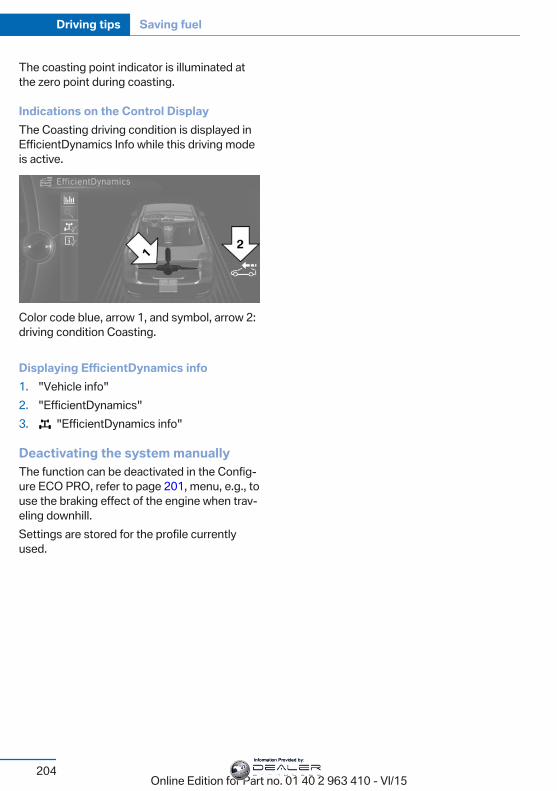
The coasting point indicator is illuminated atthe zero point during coasting.
Indications on the Control DisplayThe Coasting driving condition is displayed inEfficientDynamics Info while this driving modeis active.
Color code blue, arrow 1, and symbol, arrow 2:driving condition Coasting.
Displaying EfficientDynamics info1. "Vehicle info"2. "EfficientDynamics"3. "EfficientDynamics info"
Deactivating the system manuallyThe function can be deactivated in the Config‐ure ECO PRO, refer to page 201, menu, e.g., touse the braking effect of the engine when trav‐eling downhill.Settings are stored for the profile currentlyused.
Seite 204
Driving tips Saving fuel
204Online Edition for Part no. 01 40 2 963 410 - VI/15
Information Provided by:

Seite 205
Saving fuel Driving tips
205Online Edition for Part no. 01 40 2 963 410 - VI/15
Information Provided by:
Online Edition for Part no. 01 40 2 963 410 - VI/15
Information Provided by:
MobilityIn order to always ensure your mobility, you will
find important information on operating fluids,wheels and tires, maintenance and Roadside
Assistance in the following.
Online Edition for Part no. 01 40 2 963 410 - VI/15
Information Provided by:
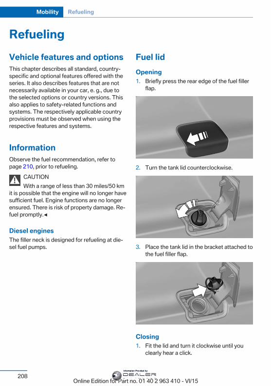
RefuelingVehicle features and optionsThis chapter describes all standard, country-specific and optional features offered with theseries. It also describes features that are notnecessarily available in your car, e. g., due tothe selected options or country versions. Thisalso applies to safety-related functions andsystems. The respectively applicable countryprovisions must be observed when using therespective features and systems.
InformationObserve the fuel recommendation, refer topage 210, prior to refueling.
CAUTIONWith a range of less than 30 miles/50 km
it is possible that the engine will no longer havesufficient fuel. Engine functions are no longerensured. There is risk of property damage. Re‐fuel promptly.◀
Diesel enginesThe filler neck is designed for refueling at die‐sel fuel pumps.
Fuel lidOpening1. Briefly press the rear edge of the fuel filler
flap.
2. Turn the tank lid counterclockwise.
3. Place the tank lid in the bracket attached tothe fuel filler flap.
Closing1. Fit the lid and turn it clockwise until you
clearly hear a click.
Seite 208
Mobility Refueling
208Online Edition for Part no. 01 40 2 963 410 - VI/15
Information Provided by:
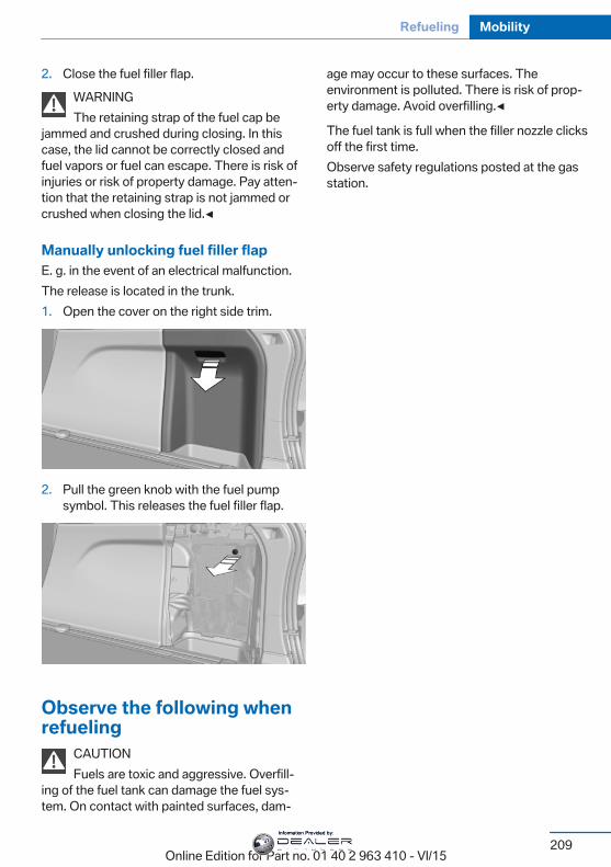
2. Close the fuel filler flap.WARNINGThe retaining strap of the fuel cap be
jammed and crushed during closing. In thiscase, the lid cannot be correctly closed andfuel vapors or fuel can escape. There is risk ofinjuries or risk of property damage. Pay atten‐tion that the retaining strap is not jammed orcrushed when closing the lid.◀
Manually unlocking fuel filler flapE. g. in the event of an electrical malfunction.The release is located in the trunk.1. Open the cover on the right side trim.
2. Pull the green knob with the fuel pumpsymbol. This releases the fuel filler flap.
Observe the following whenrefueling
CAUTIONFuels are toxic and aggressive. Overfill‐
ing of the fuel tank can damage the fuel sys‐tem. On contact with painted surfaces, dam‐
age may occur to these surfaces. Theenvironment is polluted. There is risk of prop‐erty damage. Avoid overfilling.◀
The fuel tank is full when the filler nozzle clicksoff the first time.Observe safety regulations posted at the gasstation.
Seite 209
Refueling Mobility
209Online Edition for Part no. 01 40 2 963 410 - VI/15
Information Provided by:
FuelVehicle features and optionsThis chapter describes all standard, country-specific and optional features offered with theseries. It also describes features that are notnecessarily available in your car, e. g., due tothe selected options or country versions. Thisalso applies to safety-related functions andsystems. The respectively applicable countryprovisions must be observed when using therespective features and systems.
Fuel recommendationGeneral informationDepending on the region, many gas stationssell fuel that has been customized to winter orsummer conditions. Fuel that is available inwinter helps make a cold start easier, e.g.
InformationCAUTIONEven fuels that conform to the specifica‐
tions can be of low quality. This may cause en‐gine problems, for instance poor engine start-up behavior, poor handling and/or poorperformance. There is risk of property damage.In case of engine problems, switch gas sta‐tions or use a brand name fuel with a higheroctane rating.◀
GasolineFor the best fuel efficiency, the gasolineshould be sulfur-free or very low in sulfur con‐tent.Fuels that are marked on the gas pump as con‐taining metal must not be used.
CAUTIONEven small amounts of wrong fuel or
wrong fuel additives can damage the fuel sys‐tem and the engine. Furthermore, the catalyticconverter is permanently damaged. There isrisk of property damage. Do not refuel or addthe following in the case of gasoline engines:▷ Leaded gasoline.▷ Metallic additives, e.g. manganese or iron.Do not press the Start/Stop button after refuel‐ing the wrong fuel. Contact a dealer’s servicecenter or another qualified service center or re‐pair shop.◀
Fuels with a maximum ethanol content of10 %, i. e., E10, may be used for refueling.Ethanol should satisfy the following qualitystandards:US: ASTM 4806–xxCAN: CGSB-3.511–xxxx: comply with the current standard in eachcase.
CAUTIONWrong fuels can damage the fuel system
and the engine. There is risk of property dam‐age. Do not use a fuel with a higher ethanolpercentage than recommended or one withother types of alcohol, e.g. M5 to M100.◀
Recommended fuel gradeBMW recommends AKI 91.
Minimum fuel gradeBMW recommends AKI 89.
CAUTIONFuel that does not comply with the mini‐
mum quality can compromise engine functionor cause engine damage. There is risk of prop‐
Seite 210
Mobility Fuel
210Online Edition for Part no. 01 40 2 963 410 - VI/15
Information Provided by:
erty damage. Do not fill with fuel that does notcomply with the minimum quality.◀
If you use gasoline with this minimum AKI Rat‐ing, the engine may produce knocking soundswhen starting at high outside temperatures.This has no effect on the engine life.
CAUTIONThe use of poor-quality fuels may result
in harmful engine deposits or damage. Addi‐tionally, problems relating to drivability, start‐ing and stalling, especially under certain envi‐ronmental conditions such as high ambienttemperature and high altitude, may occur.If drivability problems are encountered, we rec‐ommend switching to a high quality gasolinebrand and a higher octane grade — AKI num‐ber — for a few tank fills. To avoid harmful en‐gine deposits, it is highly recommended topurchase gasoline from Top Tier retailers.Failure to comply with these recommendationsmay result in the need for unscheduled main‐tenance.◀
DieselCAUTIONEven small amounts of wrong fuel or
wrong fuel additives can damage the fuel sys‐tem and the engine. There is risk of propertydamage.Observe the following for diesel engines:▷ Use only Ultra-Low Sulfur Diesel. Maxi‐
mum content of biodiesel: 5 %, B5.▷ Do not use rapeseed methyl ester RME.▷ Do not use biodiesel above 5 %, B5.▷ Do not use gasoline.▷ No diesel additives.Do not press the Start/Stop button after refuel‐ing the wrong fuel. Contact a dealer’s servicecenter or another qualified service center or re‐pair shop.◀
Low-Sulfur DieselThe engine of your BMW is designed for dieselwith low sulfur content:Ultra-Low Sulfur Diesel ASTM D 975-xx.xx: comply with the current standard in eachcase.Use only Ultra-Low Sulfur Diesel.The fraction of biodiesel in the fuel must notexceed 5%, referred to as B5. Do not use gas‐oline. If you do fill the tank with the wrong fuel,e.g., gasoline, do not start the engine as thismay damage the engine.In the case of incorrect refueling, contact adealer’s service center or another qualifiedservice center or repair shop or Roadside As‐sistance.If the fuel pump nozzle does not fit in the fillerpipe of your BMW, please check to ensure thatyou are refueling at a diesel fuel pump that isequipped with a diesel fuel pump nozzle.In the event the Ultra-Low Sulfur Diesel fuelcannot be fully inserted into the fuel filler neck,please contact BMW Roadside Assistance forinstructions on how to add fuel.For more information on Roadside Assistance,refer to Owner's Manual for Navigation, Enter‐tainment and Communication.
BMW Advanced DieselThe conceptBMW Advanced Diesel reduces nitrogen ox‐ides in the diesel emissions by injecting Dieselexhaust fluid into the exhaust system. A chem‐ical reaction takes place inside the catalyticconverter that minimizes nitrogen oxides.The vehicle has two tanks, the active tank andthe passive tank. The active tank can be refil‐led in the engine compartment. BMW recom‐mends that the passive tank is filled up by thedealer’s service center within the course ofregular maintenance.
Seite 211
Fuel Mobility
211Online Edition for Part no. 01 40 2 963 410 - VI/15
Information Provided by:
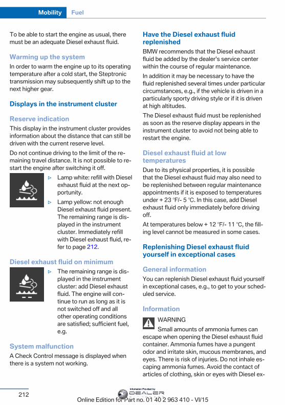
To be able to start the engine as usual, theremust be an adequate Diesel exhaust fluid.
Warming up the systemIn order to warm the engine up to its operatingtemperature after a cold start, the Steptronictransmission may subsequently shift up to thenext higher gear.
Displays in the instrument cluster
Reserve indicationThis display in the instrument cluster providesinformation about the distance that can still bedriven with the current reserve level.Do not continue driving to the limit of the re‐maining travel distance. It is not possible to re‐start the engine after switching it off.
▷ Lamp white: refill with Dieselexhaust fluid at the next op‐portunity.
▷ Lamp yellow: not enoughDiesel exhaust fluid present.The remaining range is dis‐played in the instrumentcluster. Immediately refillwith Diesel exhaust fluid, re‐fer to page 212.
Diesel exhaust fluid on minimum▷ The remaining range is dis‐
played in the instrumentcluster: add Diesel exhaustfluid. The engine will con‐tinue to run as long as it isnot switched off and allother operating conditionsare satisfied; sufficient fuel,e.g.
System malfunctionA Check Control message is displayed whenthere is a system not working.
Have the Diesel exhaust fluidreplenishedBMW recommends that the Diesel exhaustfluid be added by the dealer’s service centerwithin the course of regular maintenance.In addition it may be necessary to have thefluid replenished several times under particularcircumstances, e.g., if the vehicle is driven in aparticularly sporty driving style or if it is drivenat high altitudes.The Diesel exhaust fluid must be replenishedas soon as the reserve display appears in theinstrument cluster to avoid not being able torestart the engine.
Diesel exhaust fluid at lowtemperaturesDue to its physical properties, it is possiblethat the Diesel exhaust fluid may also need tobe replenished between regular maintenanceappointments if it is exposed to temperaturesunder + 23 ℉/- 5 ℃. In this case, add Dieselexhaust fluid only immediately before drivingoff.At temperatures below + 12 ℉/- 11 ℃, the fill‐ing level cannot be measured in some cases.
Replenishing Diesel exhaust fluidyourself in exceptional cases
General informationYou can replenish Diesel exhaust fluid yourselfin exceptional cases, e.g., to get to your sched‐uled service.
InformationWARNINGSmall amounts of ammonia fumes can
escape when opening the Diesel exhaust fluidcontainer. Ammonia fumes have a pungentodor and irritate skin, mucous membranes, andeyes. There is risk of injuries. Do not inhale es‐caping ammonia fumes. Avoid the contact ofarticles of clothing, skin or eyes with Diesel ex‐
Seite 212
Mobility Fuel
212Online Edition for Part no. 01 40 2 963 410 - VI/15
Information Provided by:
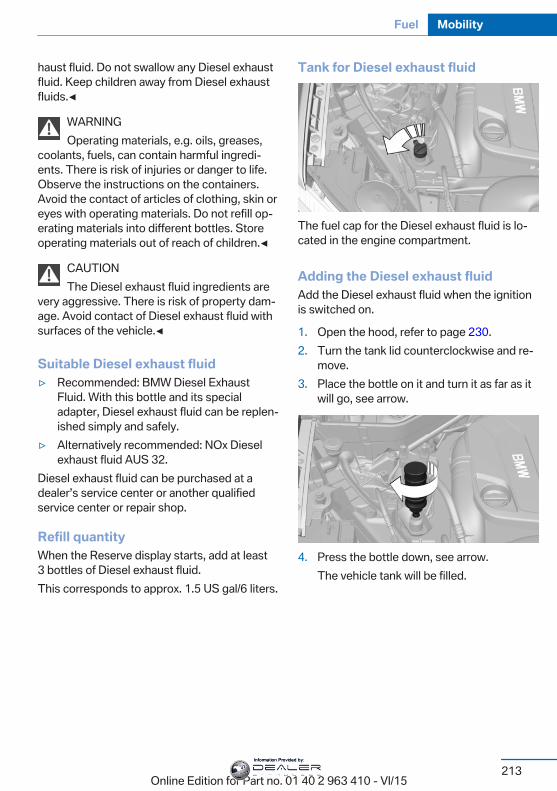
haust fluid. Do not swallow any Diesel exhaustfluid. Keep children away from Diesel exhaustfluids.◀
WARNINGOperating materials, e.g. oils, greases,
coolants, fuels, can contain harmful ingredi‐ents. There is risk of injuries or danger to life.Observe the instructions on the containers.Avoid the contact of articles of clothing, skin oreyes with operating materials. Do not refill op‐erating materials into different bottles. Storeoperating materials out of reach of children.◀
CAUTIONThe Diesel exhaust fluid ingredients are
very aggressive. There is risk of property dam‐age. Avoid contact of Diesel exhaust fluid withsurfaces of the vehicle.◀
Suitable Diesel exhaust fluid▷ Recommended: BMW Diesel Exhaust
Fluid. With this bottle and its specialadapter, Diesel exhaust fluid can be replen‐ished simply and safely.
▷ Alternatively recommended: NOx Dieselexhaust fluid AUS 32.
Diesel exhaust fluid can be purchased at adealer’s service center or another qualifiedservice center or repair shop.
Refill quantityWhen the Reserve display starts, add at least3 bottles of Diesel exhaust fluid.This corresponds to approx. 1.5 US gal/6 liters.
Tank for Diesel exhaust fluid
The fuel cap for the Diesel exhaust fluid is lo‐cated in the engine compartment.
Adding the Diesel exhaust fluidAdd the Diesel exhaust fluid when the ignitionis switched on.
1. Open the hood, refer to page 230.2. Turn the tank lid counterclockwise and re‐
move.3. Place the bottle on it and turn it as far as it
will go, see arrow.
4. Press the bottle down, see arrow.The vehicle tank will be filled.
Seite 213
Fuel Mobility
213Online Edition for Part no. 01 40 2 963 410 - VI/15
Information Provided by:
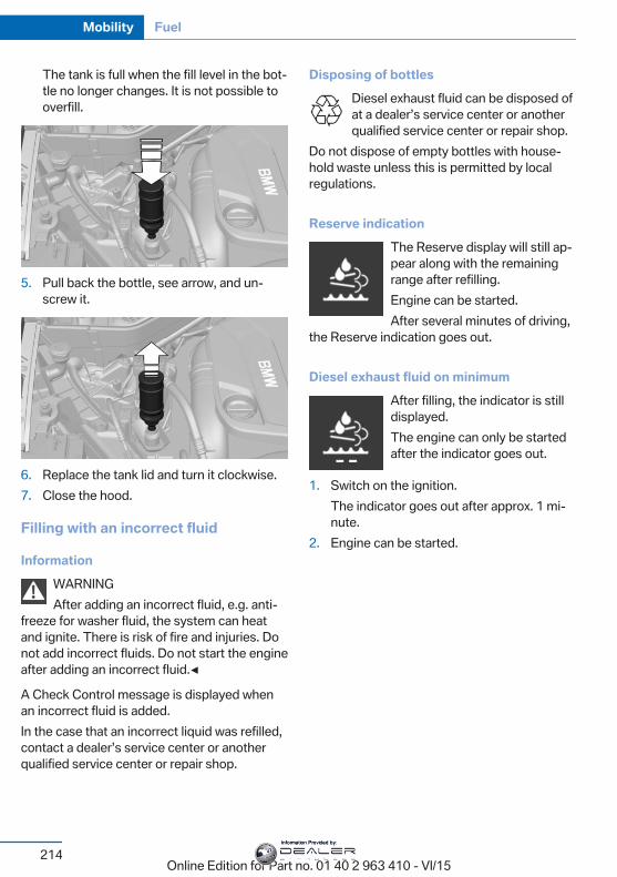
The tank is full when the fill level in the bot‐tle no longer changes. It is not possible tooverfill.
5. Pull back the bottle, see arrow, and un‐screw it.
6. Replace the tank lid and turn it clockwise.7. Close the hood.
Filling with an incorrect fluid
InformationWARNINGAfter adding an incorrect fluid, e.g. anti‐
freeze for washer fluid, the system can heatand ignite. There is risk of fire and injuries. Donot add incorrect fluids. Do not start the engineafter adding an incorrect fluid.◀
A Check Control message is displayed whenan incorrect fluid is added.In the case that an incorrect liquid was refilled,contact a dealer’s service center or anotherqualified service center or repair shop.
Disposing of bottlesDiesel exhaust fluid can be disposed ofat a dealer’s service center or anotherqualified service center or repair shop.
Do not dispose of empty bottles with house‐hold waste unless this is permitted by localregulations.
Reserve indicationThe Reserve display will still ap‐pear along with the remainingrange after refilling.Engine can be started.After several minutes of driving,
the Reserve indication goes out.
Diesel exhaust fluid on minimumAfter filling, the indicator is stilldisplayed.The engine can only be startedafter the indicator goes out.
1. Switch on the ignition.The indicator goes out after approx. 1 mi‐nute.
2. Engine can be started.
Seite 214
Mobility Fuel
214Online Edition for Part no. 01 40 2 963 410 - VI/15
Information Provided by:
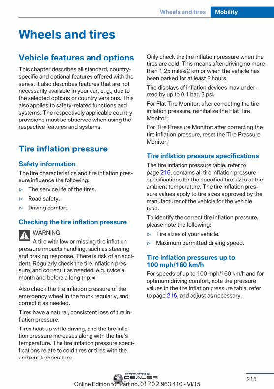
Wheels and tiresVehicle features and optionsThis chapter describes all standard, country-specific and optional features offered with theseries. It also describes features that are notnecessarily available in your car, e. g., due tothe selected options or country versions. Thisalso applies to safety-related functions andsystems. The respectively applicable countryprovisions must be observed when using therespective features and systems.
Tire inflation pressureSafety informationThe tire characteristics and tire inflation pres‐sure influence the following:▷ The service life of the tires.▷ Road safety.▷ Driving comfort.
Checking the tire inflation pressureWARNINGA tire with low or missing tire inflation
pressure impacts handling, such as steeringand braking response. There is risk of an acci‐dent. Regularly check the tire inflation pres‐sure, and correct it as needed, e.g. twice amonth and before a long trip.◀
Also check the tire inflation pressure of theemergency wheel in the trunk regularly, andcorrect it as needed.Tires have a natural, consistent loss of tire in‐flation pressure.Tires heat up while driving, and the tire infla‐tion pressure increases along with the tire'stemperature. The tire inflation pressure speci‐fications relate to cold tires or tires with theambient temperature.
Only check the tire inflation pressure when thetires are cold. This means after driving no morethan 1.25 miles/2 km or when the vehicle hasbeen parked for at least 2 hours.The displays of inflation devices may under-read by up to 0.1 bar, 2 psi.For Flat Tire Monitor: after correcting the tireinflation pressure, reinitialize the Flat TireMonitor.For Tire Pressure Monitor: after correcting thetire inflation pressure, reset the Tire PressureMonitor.
Tire inflation pressure specificationsThe tire inflation pressure table, refer topage 216, contains all tire inflation pressurespecifications for the specified tire sizes at theambient temperature. The tire inflation pres‐sure values apply to tire sizes approved by themanufacturer of the vehicle for the vehicletype.To identify the correct tire inflation pressure,please note the following:▷ Tire sizes of your vehicle.▷ Maximum permitted driving speed.
Tire inflation pressures up to100 mph/160 km/hFor speeds of up to 100 mph/160 km/h and foroptimum driving comfort, note the pressurevalues in the tire inflation pressure table, referto page 216, and adjust as necessary.
Seite 215
Wheels and tires Mobility
215Online Edition for Part no. 01 40 2 963 410 - VI/15
Information Provided by:
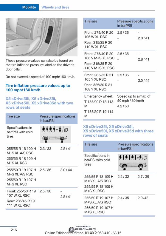
These pressure values can also be found onthe tire inflation pressure label on the driver'sdoor pillar.
Do not exceed a speed of 100 mph/160 km/h.
Tire inflation pressure values up to100 mph/160 km/h
X5 sDrive35i, X5 xDrive35i,X5 xDrive50i, X5 xDrive35d with tworows of seats
Tire size Pressure specificationsin bar/PSI
Specifications inbar/PSI with coldtires
255/55 R 18 109 HM+S XL A/S RSC255/55 R 18 109 HM+S XL RSC
2.3 / 33 2.8 / 41
255/50 R 19 107 HM+S XL A/S RSC255/50 R 19 107 HM+S XL RSC
2.5 / 36 3.0 / 44
Front: 255/50 R 19107 W XL RSCRear: 285/45 R 19111 W XL RSC
2.5 / 36-
-2.8 / 41
Tire size Pressure specificationsin bar/PSI
Front: 275/40 R 20106 W XL RSCRear: 315/35 R 20110 W XL RSC
2.5 / 36-
-2.8 / 41
Front: 275/40 R 20106 V M+S XL RSCRear: 315/35 R 20110 V M+S XL RSC
2.5 / 36-
-2.8 / 41
Front: 285/35 R 21105 Y XL RSCRear: 325/30 R 21108 Y XL RSC
2.5 / 36-
-3.0 / 44
Emergency wheel:T 155/90 D 18 113MT 155/80 R 19 114M
Speed up to a max. of50 mph / 80 km/h4.2 / 60
X5 sDrive35i, X5 xDrive35i,X5 xDrive50i, X5 xDrive35d with threerows of seats
Tire size Pressure specificationsin bar/PSI
Specifications inbar/PSI with coldtires
255/55 R 18 109 HM+S XL A/S RSC255/55 R 18 109 HM+S XL RSC
2.2 / 32 2.7 / 39
255/50 R 19 107 HM+S XL A/S RSC255/50 R 19 107 HM+S XL RSC
2.4 / 35 2.9 /42
Seite 216
Mobility Wheels and tires
216Online Edition for Part no. 01 40 2 963 410 - VI/15
Information Provided by:
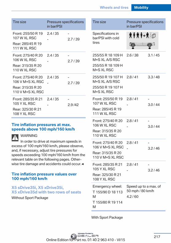
Tire size Pressure specificationsin bar/PSI
Front: 255/50 R 19107 W XL RSCRear: 285/45 R 19111 W XL RSC
2.4 / 35-
-2.7 / 39
Front: 275/40 R 20106 W XL RSCRear: 315/35 R 20110 W XL RSC
2.4 / 35-
-2.7 / 39
Front: 275/40 R 20106 V M+S XL RSCRear: 315/35 R 20110 V M+S XL RSC
2.4 / 35-
-2.7 / 39
Front: 285/35 R 21105 Y XL RSCRear: 325/30 R 21108 Y XL RSC
2.4 / 35-
-2.9 /42
Tire inflation pressures at max.speeds above 100 mph/160 km/h
WARNINGIn order to drive at maximum speeds in
excess of 100 mph/160 km/h, please observe,and, if necessary, adjust tire pressures forspeeds exceeding 100 mph/160 km/h from therelevant table on the following pages. Other‐wise tire damage and accidents could occur.◀
Tire inflation pressure values over100 mph/160 km/h
X5 sDrive35i, X5 xDrive35i,X5 xDrive35d with two rows of seatsWithout Sport Package
Tire size Pressure specificationsin bar/PSI
Specifications inbar/PSI with coldtires
255/55 R 18 109 HM+S XL A/S RSC255/55 R 18 109 HM+S XL RSC
2.6 / 38 3.1 / 45
255/50 R 19 107 HM+S XL A/S RSC255/50 R 19 107 HM+S XL RSC
2.8 / 41 3.3 / 48
Front: 255/50 R 19107 W XL RSCRear: 285/45 R 19111 W XL RSC
2.8 / 41-
-3.0 / 44
Front: 275/40 R 20106 W XL RSCRear: 315/35 R 20110 W XL RSC
2.8 / 41-
-3.0 / 44
Front: 275/40 R 20106 V M+S XL RSCRear: 315/35 R 20110 V M+S XL RSC
2.8 / 41-
-3.2 / 46
Front: 285/35 R 21105 Y XL RSCRear: 325/30 R 21108 Y XL RSC
2.8 / 41-
-3.2 / 46
Emergency wheel:T 155/90 D 18 113MT 155/80 R 19 114M
Speed up to a max. of50 mph / 80 km/h4.2 / 60
With Sport Package
Seite 217
Wheels and tires Mobility
217Online Edition for Part no. 01 40 2 963 410 - VI/15
Information Provided by:
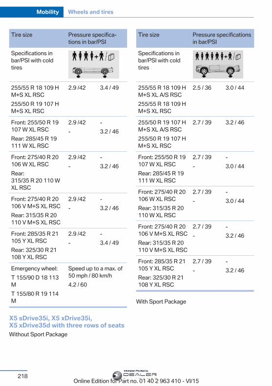
Tire size Pressure specifica‐tions in bar/PSI
Specifications inbar/PSI with coldtires
255/55 R 18 109 HM+S XL RSC255/50 R 19 107 HM+S XL RSC
2.9 /42 3.4 / 49
Front: 255/50 R 19107 W XL RSCRear: 285/45 R 19111 W XL RSC
2.9 /42-
-3.2 / 46
Front: 275/40 R 20106 W XL RSCRear:315/35 R 20 110 WXL RSC
2.9 /42-
-3.2 / 46
Front: 275/40 R 20106 V M+S XL RSCRear: 315/35 R 20110 V M+S XL RSC
2.9 /42-
-3.2 / 46
Front: 285/35 R 21105 Y XL RSCRear: 325/30 R 21108 Y XL RSC
2.9 /42-
-3.4 / 49
Emergency wheel:T 155/90 D 18 113MT 155/80 R 19 114M
Speed up to a max. of50 mph / 80 km/h4.2 / 60
X5 sDrive35i, X5 xDrive35i,X5 xDrive35d with three rows of seatsWithout Sport Package
Tire size Pressure specificationsin bar/PSI
Specifications inbar/PSI with coldtires
255/55 R 18 109 HM+S XL A/S RSC255/55 R 18 109 HM+S XL RSC
2.5 / 36 3.0 / 44
255/50 R 19 107 HM+S XL A/S RSC255/50 R 19 107 HM+S XL RSC
2.7 / 39 3.2 / 46
Front: 255/50 R 19107 W XL RSCRear: 285/45 R 19111 W XL RSC
2.7 / 39-
-3.0 / 44
Front: 275/40 R 20106 W XL RSCRear: 315/35 R 20110 W XL RSC
2.7 / 39-
-3.0 / 44
Front: 275/40 R 20106 V M+S XL RSCRear: 315/35 R 20110 V M+S XL RSC
2.7 / 39-
-3.2 / 46
Front: 285/35 R 21105 Y XL RSCRear: 325/30 R 21108 Y XL RSC
2.7 / 39-
-3.2 / 46
With Sport Package
Seite 218
Mobility Wheels and tires
218Online Edition for Part no. 01 40 2 963 410 - VI/15
Information Provided by:
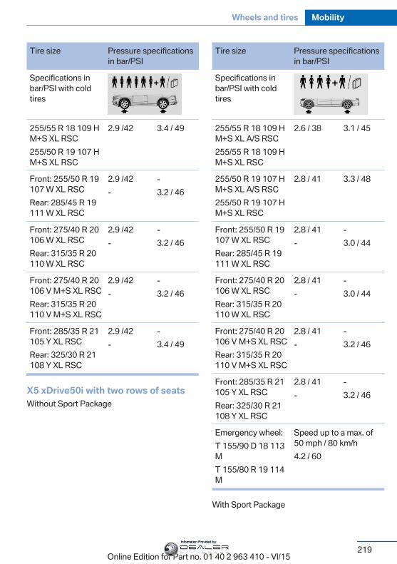
Tire size Pressure specificationsin bar/PSI
Specifications inbar/PSI with coldtires
255/55 R 18 109 HM+S XL RSC255/50 R 19 107 HM+S XL RSC
2.9 /42 3.4 / 49
Front: 255/50 R 19107 W XL RSCRear: 285/45 R 19111 W XL RSC
2.9 /42-
-3.2 / 46
Front: 275/40 R 20106 W XL RSCRear: 315/35 R 20110 W XL RSC
2.9 /42-
-3.2 / 46
Front: 275/40 R 20106 V M+S XL RSCRear: 315/35 R 20110 V M+S XL RSC
2.9 /42-
-3.2 / 46
Front: 285/35 R 21105 Y XL RSCRear: 325/30 R 21108 Y XL RSC
2.9 /42-
-3.4 / 49
X5 xDrive50i with two rows of seatsWithout Sport Package
Tire size Pressure specificationsin bar/PSI
Specifications inbar/PSI with coldtires
255/55 R 18 109 HM+S XL A/S RSC255/55 R 18 109 HM+S XL RSC
2.6 / 38 3.1 / 45
255/50 R 19 107 HM+S XL A/S RSC255/50 R 19 107 HM+S XL RSC
2.8 / 41 3.3 / 48
Front: 255/50 R 19107 W XL RSCRear: 285/45 R 19111 W XL RSC
2.8 / 41-
-3.0 / 44
Front: 275/40 R 20106 W XL RSCRear: 315/35 R 20110 W XL RSC
2.8 / 41-
-3.0 / 44
Front: 275/40 R 20106 V M+S XL RSCRear: 315/35 R 20110 V M+S XL RSC
2.8 / 41-
-3.2 / 46
Front: 285/35 R 21105 Y XL RSCRear: 325/30 R 21108 Y XL RSC
2.8 / 41-
-3.2 / 46
Emergency wheel:T 155/90 D 18 113MT 155/80 R 19 114M
Speed up to a max. of50 mph / 80 km/h4.2 / 60
With Sport Package
Seite 219
Wheels and tires Mobility
219Online Edition for Part no. 01 40 2 963 410 - VI/15
Information Provided by:
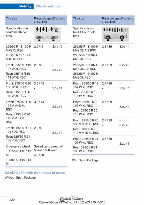
Tire size Pressure specificationsin bar/PSI
Specifications inbar/PSI with coldtires
255/55 R 18 109 HM+S XL RSC255/50 R 19 107 HM+S XL RSC
2.9 /42 3.4 / 49
Front: 255/50 R 19107 W XL RSCRear: 285/45 R 19111 W XL RSC
2.9 /42-
-3.4 / 49
Front: 275/40 R 20106 W XL RSCRear: 315/35 R 20110 W XL RSC
3.0 / 44-
-3.5 / 51
Front: 275/40 R 20106 V M+S XLRSCRear: 315/35 R 20110 V M+S XLRSC
3.0 / 44-
-3.5 / 51
Front: 285/35 R 21105 Y XL RSCRear: 325/30 R 21108 Y XL RSC
2.9 /42-
-3.4 / 49
Emergency wheel:T 155/90 D 18 113MT 155/80 R 19 114M
Speed up to a max. of50 mph / 80 km/h4.2 / 60
X5 xDrive50i with three rows of seatsWithout Sport Package
Tire size Pressure specificationsin bar/PSI
Specifications inbar/PSI with coldtires
255/55 R 18 109 HM+S XL A/S RSC255/55 R 18 109 HM+S XL RSC
2.5 / 36 3.0 / 44
255/50 R 19 107 HM+S XL A/S RSC255/50 R 19 107 HM+S XL RSC
2.7 / 39 3.2 / 46
Front: 255/50 R 19107 W XL RSCRear: 285/45 R 19111 W XL RSC
2.7 / 39-
-3.0 / 44
Front: 275/40 R 20106 W XL RSCRear: 315/35 R 20110 W XL RSC
2.7 / 39-
-3.0 / 44
Front: 275/40 R 20106 V M+S XL RSCRear: 315/35 R 20110 V M+S XL RSC
2.7 / 39-
-3.2 / 46
Front: 285/35 R 21105 W XL RSCRear: 325/30 R 21108 W XL RSC
2.7 / 39-
-3.2 / 46
With Sport Package
Seite 220
Mobility Wheels and tires
220Online Edition for Part no. 01 40 2 963 410 - VI/15
Information Provided by:
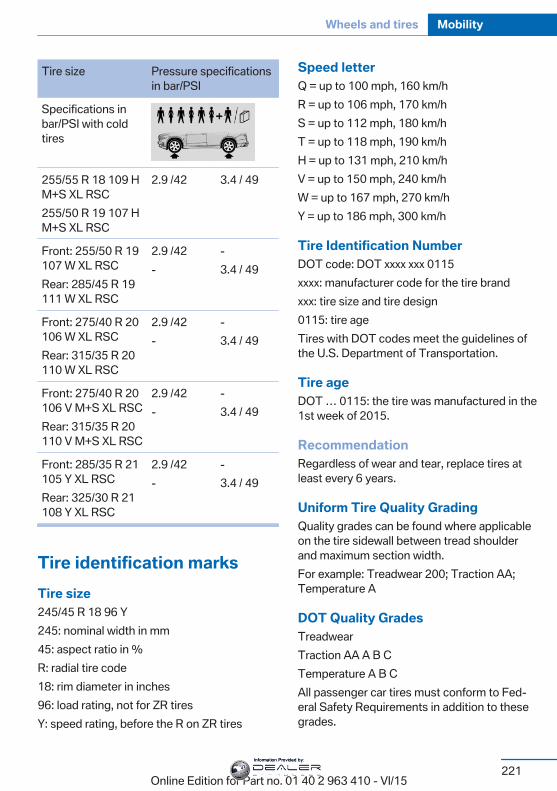
Tire size Pressure specificationsin bar/PSI
Specifications inbar/PSI with coldtires
255/55 R 18 109 HM+S XL RSC255/50 R 19 107 HM+S XL RSC
2.9 /42 3.4 / 49
Front: 255/50 R 19107 W XL RSCRear: 285/45 R 19111 W XL RSC
2.9 /42-
-3.4 / 49
Front: 275/40 R 20106 W XL RSCRear: 315/35 R 20110 W XL RSC
2.9 /42-
-3.4 / 49
Front: 275/40 R 20106 V M+S XL RSCRear: 315/35 R 20110 V M+S XL RSC
2.9 /42-
-3.4 / 49
Front: 285/35 R 21105 Y XL RSCRear: 325/30 R 21108 Y XL RSC
2.9 /42-
-3.4 / 49
Tire identification marksTire size245/45 R 18 96 Y245: nominal width in mm45: aspect ratio in %R: radial tire code18: rim diameter in inches96: load rating, not for ZR tiresY: speed rating, before the R on ZR tires
Speed letterQ = up to 100 mph, 160 km/hR = up to 106 mph, 170 km/hS = up to 112 mph, 180 km/hT = up to 118 mph, 190 km/hH = up to 131 mph, 210 km/hV = up to 150 mph, 240 km/hW = up to 167 mph, 270 km/hY = up to 186 mph, 300 km/h
Tire Identification NumberDOT code: DOT xxxx xxx 0115xxxx: manufacturer code for the tire brandxxx: tire size and tire design0115: tire ageTires with DOT codes meet the guidelines ofthe U.S. Department of Transportation.
Tire ageDOT … 0115: the tire was manufactured in the1st week of 2015.
RecommendationRegardless of wear and tear, replace tires atleast every 6 years.
Uniform Tire Quality GradingQuality grades can be found where applicableon the tire sidewall between tread shoulderand maximum section width.For example: Treadwear 200; Traction AA;Temperature A
DOT Quality GradesTreadwearTraction AA A B CTemperature A B CAll passenger car tires must conform to Fed‐eral Safety Requirements in addition to thesegrades.
Seite 221
Wheels and tires Mobility
221Online Edition for Part no. 01 40 2 963 410 - VI/15
Information Provided by:
TreadwearThe treadwear grade is a comparative ratingbased on the wear rate of the tire when testedunder controlled conditions on a specified gov‐ernment test course. For example, a tiregraded 150 would wear one and one-half, 1 g,times as well on the government course as atire graded 100. The relative performance oftires depends upon the actual conditions oftheir use, however, and may depart signifi‐cantly from the norm due to variations in driv‐ing habits, service practices and differences inroad characteristics and climate.
TractionThe traction grades, from highest to lowest,are AA, A, B, and C.Those grades represent the tire's ability tostop on wet pavement as measured undercontrolled conditions on specified governmenttest surfaces of asphalt and concrete. A tiremarked C may have poor traction performance.The traction grade assigned to this tire isbased on straight-ahead braking traction tests,and does not include acceleration, cornering,hydroplaning, or peak traction characteristics.
TemperatureThe temperature grades are A, the highest, B,and C, representing the tire's resistance to thegeneration of heat and its ability to dissipateheat when tested under controlled conditionson a specified indoor laboratory test wheel.Sustained high temperature can cause the ma‐terial of the tire to degenerate and reduce tirelife, and excessive temperature can lead tosudden tire failure. The grade C correspondsto a level of performance which all passengercar tires must meet under the Federal MotorVehicle Safety Standard No. 109. Grades BandA represent higher levels of performance onthe laboratory test wheel than the minimum re‐quired by law.
WARNINGThe temperature grade for this tire is es‐
tablished for a tire that is properly inflated andnot overloaded. Excessive speed, underinfla‐tion, or excessive loading, either separately orin combination, can cause heat buildup andpossible tire failure.◀
RSC – Run-flat tiresRun-flat tires, refer to page 225, are labeledwith a circular symbol containing the lettersRSC marked on the sidewall.
M+SWinter and all-season tires with better coldweather performance than summer tires.
Tire treadSummer tiresDo not drive with a tire tread depth of less than0.12 in/3 mm.There is an increased danger of hydroplaning ifthe tire tread depth is less than 0.12 in/3 mm.
Winter tiresDo not drive with a tire tread depth of less than0.16 in/4 mm.Below a tread depth of 0.16 in/4 mm, tires areless suitable for winter operation.
Seite 222
Mobility Wheels and tires
222Online Edition for Part no. 01 40 2 963 410 - VI/15
Information Provided by:
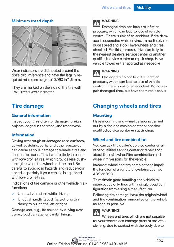
Minimum tread depth
Wear indicators are distributed around thetire's circumference and have the legally re‐quired minimum height of 0.063 in/1.6 mm.
They are marked on the side of the tire withTWI, Tread Wear Indicator.
Tire damageGeneral informationInspect your tires often for damage, foreignobjects lodged in the tread, and tread wear.
InformationDriving over rough or damaged road surfaces,as well as debris, curbs and other obstaclescan cause serious damage to wheels, tires andsuspension parts. This is more likely to occurwith low-profile tires, which provide less cush‐ioning between the wheel and the road. Becareful to avoid road hazards and reduce yourspeed, especially if your vehicle is equippedwith low-profile tires.Indications of tire damage or other vehicle mal‐functions:▷ Unusual vibrations while driving.▷ Unusual handling such as a strong ten‐
dency to pull to the left or right.Damage can, e. g., be caused by driving overcurbs, road damage, or similar things.
WARNINGDamaged tires can lose tire inflation
pressure, which can lead to loss of vehiclecontrol. There is risk of an accident. If tire dam‐age is suspected while driving, immediately re‐duce speed and stop. Have wheels and tireschecked. For this purpose, drive carefully tothe nearest dealer’s service center or anotherqualified service center or repair shop. Havevehicle towed or transported as needed.◀
WARNINGDamaged tires can lose tire inflation
pressure, which can lead to loss of vehiclecontrol. There is risk of an accident. Do not re‐pair damaged tires, but have them replaced.◀
Changing wheels and tiresMountingHave mounting and wheel balancing carriedout by a dealer’s service center or anotherqualified service center or repair shop.
Wheel and tire combinationYou can ask the dealer’s service center or an‐other qualified service center or repair shopabout the right wheel/tire combination andwheel rim versions for the vehicle.Incorrect wheel and tire combinations impairthe function of a variety of systems such asABS or DSC.To maintain good handling and vehicle re‐sponse, use only tires with a single tread con‐figuration from a single manufacturer.Following tire damage, have the original wheeland tire combination remounted on the vehicleas soon as possible.
WARNINGWheels and tires which are not suitable
for your vehicle can damage parts of the vehi‐cle, e. g. due to contact with the body due to
Seite 223
Wheels and tires Mobility
223Online Edition for Part no. 01 40 2 963 410 - VI/15
Information Provided by:
tolerances despite the same official size rating.There is risk of an accident.◀
Recommended tire brands
For each tire size, the manufacturer of your ve‐hicle recommends certain tire brands. Thesecan be identified by a star on the tire sidewall.
New tiresTire traction is not optimal due to manufactur‐ing circumstances when tires are brand-new;they achieve their full traction potential after abreak-in time.Drive conservatively for the first200 miles/300 km.
Retreaded tiresThe manufacturer of your vehicle does not rec‐ommend the use of retreaded tires.
WARNINGRetreated tires can have different tire
casing structures. With advanced age the serv‐ice life can be limited. There is risk of an acci‐dent. Do not use retreated tires.◀
Winter tiresWinter tires are recommended for operating onwinter roads.Although so-called all-season M+S tires pro‐vide better winter traction than summer tires,they do not provide the same level of perform‐ance as winter tires.
Maximum speed of winter tiresIf the maximum speed of the vehicle is higherthan the permissible speed for the winter tires,then a respective symbol is displayed in yourfield of vision. The plate is available from adealer’s service center or another qualifiedservice center or repair shop.With mounted winter tires, observe and adhereto the permissible maximum speed.
Run-flat tiresIf you are already using run-flat tires, for yourown safety you should replace them only withthe same kind. No spare tire is available in thecase of a flat tire. A dealer’s service center oranother qualified service center or repair shopwill be glad to answer additional questions atany time.
Rotating wheels between axlesDifferent wear patterns can occur on the frontand rear axles depending on individual drivingconditions. The tires can be rotated betweenthe axles to achieve even wear. A dealer’sservice center or another qualified service cen‐ter or repair shop will be glad to answer addi‐tional questions at any time. After rotating,check the tire pressure and correct if needed.Rotating the tires is not permissible on vehi‐cles with different tire sizes or rim sizes on thefront and rear axles.
StorageStore wheels and tires in a cool, dry place withas little exposure to light as possible.Always protect tires against all contact with oil,grease and fuels.Do not exceed the maximum tire inflation pres‐sure indicated on the side wall of the tire.
Seite 224
Mobility Wheels and tires
224Online Edition for Part no. 01 40 2 963 410 - VI/15
Information Provided by:
Run-flat tiresLabel
RSC label on the tire sidewall.The wheels consist of tires that are self-sup‐porting, to a limited degree, and possibly spe‐cial rims.The support of the sidewall allows the tire toremain drivable to a restricted degree in theevent of a tire inflation pressure loss.
Follow the instructions for continued drivingwith a flat tire.
Changing run-flat tiresFor your own safety, only use run-flat tires. Nospare tire is available in the case of a flat tire. Adealer’s service center or another qualifiedservice center or repair shop will be glad to an‐swer additional questions at any time.
Mobility SystemThe conceptWith the Mobility System, minor tire damagecan be sealed quickly to enable continuedtravel. To accomplish this, sealant is pumpedinto the tires, which seals the damage from theinside.The compressor can be used to check the tireinflation pressure.
Information▷ Follow the instructions on using the Mobi‐
lity System found on the compressor andsealant container.
▷ Use of the Mobility System may be ineffec‐tive if the tire puncture measures approx.1/8 in/4 mm or more.
▷ Contact a dealer’s service center or an‐other qualified service center or repairshop if the tire cannot be made drivable.
▷ If possible, do not remove foreign bodiesthat have penetrated the tire.
▷ Pull the speed limit sticker off the sealantcontainer and apply it to the steeringwheel.
▷ The use of a sealant can damage the TPMwheel electronics. In this case, have theelectronics checked at the next opportu‐nity and have them replaced if needed.
DANGERIf the exhaust pipe is blocked or ventila‐
tion is insufficient, harmful exhaust gases canenter into the vehicle. The exhaust gases con‐tain carbon monoxide, an odorless and color‐less but highly toxic gas. In enclosed areas, ex‐haust gases can also accumulate outside ofthe vehicle. There is danger to life. Keep theexhaust pipe free and ensure sufficient ventila‐tion.◀
StorageThe Mobility System is located behind the leftside trim in the trunk.
Seite 225
Wheels and tires Mobility
225Online Edition for Part no. 01 40 2 963 410 - VI/15
Information Provided by:
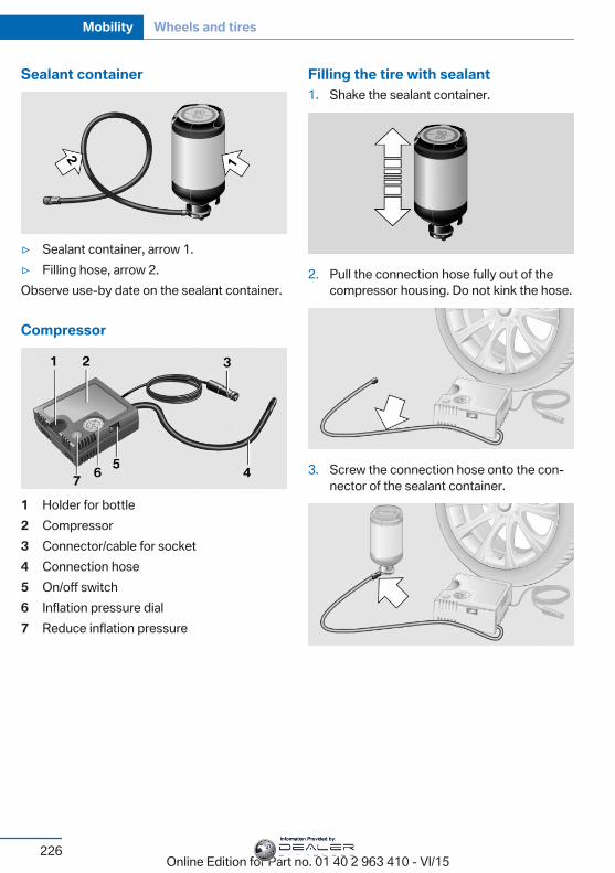
Sealant container
▷ Sealant container, arrow 1.▷ Filling hose, arrow 2.Observe use-by date on the sealant container.
Compressor
1 Holder for bottle2 Compressor3 Connector/cable for socket4 Connection hose5 On/off switch6 Inflation pressure dial7 Reduce inflation pressure
Filling the tire with sealant1. Shake the sealant container.
2. Pull the connection hose fully out of thecompressor housing. Do not kink the hose.
3. Screw the connection hose onto the con‐nector of the sealant container.
Seite 226
Mobility Wheels and tires
226Online Edition for Part no. 01 40 2 963 410 - VI/15
Information Provided by:
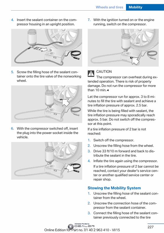
4. Insert the sealant container on the com‐pressor housing in an upright position.
5. Screw the filling hose of the sealant con‐tainer onto the tire valve of the nonworkingwheel.
6. With the compressor switched off, insertthe plug into the power socket inside thevehicle.
7. With the ignition turned on or the enginerunning, switch on the compressor.
CAUTIONThe compressor can overheat during ex‐
tended operation. There is risk of propertydamage. Do not run the compressor for morethan 10 min.◀
Let the compressor run for approx. 3 to 8 mi‐nutes to fill the tire with sealant and achieve atire inflation pressure of approx. 2.5 bar.While the tire is being filled with sealant, thetire inflation pressure may sporadically reachapprox. 5 bar. Do not switch off the compres‐sor at this point.If a tire inflation pressure of 2 bar is notreached:
1. Switch off the compressor.2. Unscrew the filling hose from the wheel.3. Drive 33 ft/10 m forward and back to dis‐
tribute the sealant in the tire.4. Inflate the tire again using the compressor.
If a tire inflation pressure of 2 bar cannot bereached, contact your dealer’s service cen‐ter or another qualified service center orrepair shop.
Stowing the Mobility System1. Unscrew the filling hose of the sealant con‐
tainer from the wheel.2. Unscrew the connection hose of the com‐
pressor from the sealant container.3. Connect the filling hose of the sealant con‐
tainer previously connected to the tire
Seite 227
Wheels and tires Mobility
227Online Edition for Part no. 01 40 2 963 410 - VI/15
Information Provided by:
valve with the available connector on thesealant container.This prevents leftover sealant from escap‐ing from the container.
4. Wrap the empty sealant container in suita‐ble material to avoid dirtying the trunk.
5. Stow the Mobility System back in the vehi‐cle.
Distributing the sealantImmediately drive approx. 5 miles/10 km to en‐sure that the sealant is evenly distributed in thetire.Do not exceed a speed of 50 mph/80 km/h.If possible, do not drive at speeds less than12 mph/20 km/h.
To correct the tire inflation pressure1. Stop at a suitable location.2. Screw the connection hose of the com‐
pressor directly onto the tire valve stem.3. Insert the connector into the power socket
inside the vehicle.4. Correct the tire inflation pressure to
2.5 bar.▷ Increase pressure: with the ignition
turned on or the engine running, switchon the compressor.
▷ To reduce the pressure: press the but‐ton on the compressor.
Continuing the tripDo not exceed the maximum permissiblespeed of 50 mph/80 km/h.Reinitialize the Flat Tire Monitor.Reinitialize the Tire Pressure Monitor.Replace the nonworking tire and the sealantcontainer of the Mobility System as soon aspossible.
Snow chainsFine-link snow chainsThe manufacturer of your vehicle recommendsuse of fine-link snow chains. Certain types offine-link snow chains have been tested by themanufacturer of the vehicle and recommendedas road-safe and suitable.Information regarding suitable snow chains isavailable from a dealer’s service center or an‐other qualified service center or repair shop.
UseUse only in pairs on the rear wheels, equippedwith the tires of the following size:▷ 255/55 R 18.▷ 255/50 R 19.Follow the snow chain manufacturer's instruc‐tions.Make sure that the snow chains are alwayssufficiently tight. Retighten as needed accord‐ing to the chain manufacturer's instructions.Do not initialize the Flat Tire Monitor aftermounting snow chains, as doing so may resultin incorrect readings.Do not initialize the Tire Pressure Monitor aftermounting snow chains, as doing so may resultin incorrect readings.When driving with snow chains, briefly activateDynamic Traction Control if needed.
Maximum speed with snow chainsDo not exceed a speed of 30 mph/50 km/hwhen using snow chains.
Seite 228
Mobility Wheels and tires
228Online Edition for Part no. 01 40 2 963 410 - VI/15
Information Provided by:
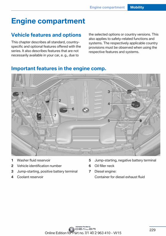
Engine compartmentVehicle features and optionsThis chapter describes all standard, country-specific and optional features offered with theseries. It also describes features that are notnecessarily available in your car, e. g., due to
the selected options or country versions. Thisalso applies to safety-related functions andsystems. The respectively applicable countryprovisions must be observed when using therespective features and systems.
Important features in the engine comp.
1 Washer fluid reservoir2 Vehicle identification number3 Jump-starting, positive battery terminal4 Coolant reservoir
5 Jump-starting, negative battery terminal6 Oil filler neck7 Diesel engine:
Container for diesel exhaust fluid
Seite 229
Engine compartment Mobility
229Online Edition for Part no. 01 40 2 963 410 - VI/15
Information Provided by:
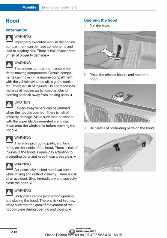
HoodInformation
WARNINGImproperly executed work in the engine
compartment can damage components andlead to a safety risk. There is risk of accidentsor risk of property damage.◀
WARNINGThe engine compartment accommo‐
dates moving components. Certain compo‐nents can move in the engine compartmentwith the vehicle switched off, e.g. the coolerfan. There is risk of injuries. Do not reach intothe area of moving parts. Keep articles ofclothing and hair away from moving parts.◀
CAUTIONFolded-away wipers can be jammed
when the hood is opened. There is risk ofproperty damage. Make sure that the wiperswith the wiper blades mounted are foldeddown onto the windshield before opening thehood.◀
WARNINGThere are protruding parts, e.g. lock
hook, on the inside of the hood. There is risk ofinjuries. If the hood is open, pay attention toprotruding parts and keep these areas clear.◀
WARNINGAn incorrectly locked hood can open
while driving and restrict visibility. There is riskof an accident. Stop immediately and correctlyclose the hood.◀
WARNINGBody parts can be jammed on opening
and closing the hood. There is risk of injuries.Make sure that the area of movement of thehood is clear during opening and closing.◀
Opening the hood1. Pull the lever.
2. Press the release handle and open thehood.
3. Be careful of protruding parts on the hood.
Seite 230
Mobility Engine compartment
230Online Edition for Part no. 01 40 2 963 410 - VI/15
Information Provided by:
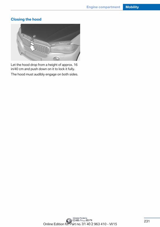
Closing the hood
Let the hood drop from a height of approx. 16in/40 cm and push down on it to lock it fully.The hood must audibly engage on both sides.
Seite 231
Engine compartment Mobility
231Online Edition for Part no. 01 40 2 963 410 - VI/15
Information Provided by:
Engine oilVehicle features and optionsThis chapter describes all standard, country-specific and optional features offered with theseries. It also describes features that are notnecessarily available in your car, e. g., due tothe selected options or country versions. Thisalso applies to safety-related functions andsystems. The respectively applicable countryprovisions must be observed when using therespective features and systems.
General informationThe engine oil consumption is dependent onthe driving style and driving conditions.The engine oil consumption can increase inthe following situations, for example:▷ Sporty driving style.▷ Break-in of the engine.▷ Idling of the engine.▷ With use of engine oil types that are not
approved.Therefore, regularly check the engine oil levelafter refueling.The vehicle is equipped with electronic oilmeasurement.The electronic oil measurement has two meas‐uring principles:▷ Status display▷ Detailed measurement
Electronic oil measurementStatus display
The conceptThe engine oil level is monitored electronicallywhile driving and shown on the Control Dis‐play.If the engine oil level reaches the minimumlevel, a check control message is displayed.
RequirementsA current measured value is available after ap‐prox. 30 minutes of driving. During a shortertrip, the status of the last, sufficiently long tripis displayed.With frequent short-distance trips, regularlyperform a detailed measurement.
Displaying the engine oil levelOn the Control Display:
1. "Vehicle info"2. "Vehicle status"3. "Engine oil level"
Engine oil level display messagesCAUTIONA too low engine oil level causes engine
damage. There is risk of property damage. Im‐mediately add engine oil.◀
Take care not to add too much engine oil.CAUTIONToo much engine oil can damage the en‐
gine or the catalytic converter. There is risk ofproperty damage. Do not add too much engineoil. Have too much engine oil siphoned off by adealer’s service center or another qualifiedservice center or repair shop.◀
Seite 232
Mobility Engine oil
232Online Edition for Part no. 01 40 2 963 410 - VI/15
Information Provided by:
Different messages appear on the display de‐pending on the engine oil level. Pay attentionto these messages.If the engine oil level is too low, within the next125 miles/200 km Add engine oil, refer topage 233.
Detailed measurement
The conceptIn the detailed measurement the engine oillevel is checked and displayed via a scale.Gasoline engine:If the engine oil level reaches the minimumlevel, a check control message is displayed.Diesel engine:If the engine oil level reaches the minimumlevel or an overfilling is detected, a check con‐trol message is displayed.During the measurement, the idle speed is in‐creased somewhat.
Requirements▷ Vehicle is on level road.▷ Steptronic transmission: selector lever in
selector lever position N or P and accelera‐tor pedal not depressed.
▷ Engine is running and is at operating tem‐perature.
Performing a detailed measurementIn order to perform a detailed measurement ofthe engine oil level:
1. "Vehicle info"2. "Vehicle status"3. "Measure engine oil level"4. "Start measurement"The engine oil level is checked and displayedvia a scale.Time: approx. 1 minute.
Adding engine oilInformation
CAUTIONA too low engine oil level causes engine
damage. There is risk of property damage.Add engine oil within the next125 miles/200 km.◀
CAUTIONToo much engine oil can damage the en‐
gine or the catalytic converter. There is risk ofproperty damage. Do not add too much engineoil. Have too much engine oil siphoned off by adealer’s service center or another qualifiedservice center or repair shop.◀
WARNINGOperating materials, e.g. oils, greases,
coolants, fuels, can contain harmful ingredi‐ents. There is risk of injuries or danger to life.Observe the instructions on the containers.Avoid the contact of articles of clothing, skin oreyes with operating materials. Do not refill op‐erating materials into different bottles. Storeoperating materials out of reach of children.◀
General informationOnly add engine oil when the message is dis‐played in the instrument cluster. The quantityto be added is indicated in the message dis‐played in the instrument cluster.Switch off the ignition and safely park the vehi‐cle before engine oil is added.
OverviewThe oil filler neck is located in the engine com‐partment, refer to page 229.
Opening the oil filler neck1. Opening the hood, refer to page 230
Seite 233
Engine oil Mobility
233Online Edition for Part no. 01 40 2 963 410 - VI/15
Information Provided by:
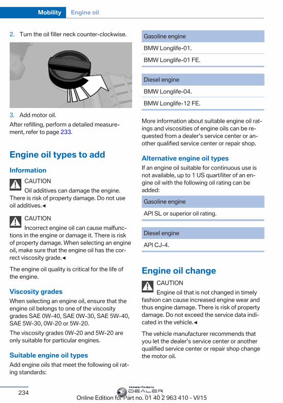
2. Turn the oil filler neck counter-clockwise.
3. Add motor oil.After refilling, perform a detailed measure‐ment, refer to page 233.
Engine oil types to addInformation
CAUTIONOil additives can damage the engine.
There is risk of property damage. Do not useoil additives.◀
CAUTIONIncorrect engine oil can cause malfunc‐
tions in the engine or damage it. There is riskof property damage. When selecting an engineoil, make sure that the engine oil has the cor‐rect viscosity grade.◀
The engine oil quality is critical for the life ofthe engine.
Viscosity gradesWhen selecting an engine oil, ensure that theengine oil belongs to one of the viscositygrades SAE 0W-40, SAE 0W-30, SAE 5W-40,SAE 5W-30, 0W-20 or 5W-20.The viscosity grades 0W-20 and 5W-20 areonly suitable for particular engines.
Suitable engine oil typesAdd engine oils that meet the following oil rat‐ing standards:
Gasoline engine
BMW Longlife-01.
BMW Longlife-01 FE.
Diesel engine
BMW Longlife-04.
BMW Longlife-12 FE.
More information about suitable engine oil rat‐ings and viscosities of engine oils can be re‐quested from a dealer’s service center or an‐other qualified service center or repair shop.
Alternative engine oil typesIf an engine oil suitable for continuous use isnot available, up to 1 US quart/liter of an en‐gine oil with the following oil rating can beadded:
Gasoline engine
API SL or superior oil rating.
Diesel engine
API CJ-4.
Engine oil changeCAUTIONEngine oil that is not changed in timely
fashion can cause increased engine wear andthus engine damage. There is risk of propertydamage. Do not exceed the service data indi‐cated in the vehicle.◀
The vehicle manufacturer recommends thatyou let the dealer’s service center or anotherqualified service center or repair shop changethe motor oil.
Seite 234
Mobility Engine oil
234Online Edition for Part no. 01 40 2 963 410 - VI/15
Information Provided by:
Seite 235
Engine oil Mobility
235Online Edition for Part no. 01 40 2 963 410 - VI/15
Information Provided by:
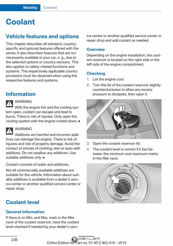
CoolantVehicle features and optionsThis chapter describes all standard, country-specific and optional features offered with theseries. It also describes features that are notnecessarily available in your car, e. g., due tothe selected options or country versions. Thisalso applies to safety-related functions andsystems. The respectively applicable countryprovisions must be observed when using therespective features and systems.
InformationWARNINGWith the engine hot and the cooling sys‐
tem open, coolant can escape and lead toburns. There is risk of injuries. Only open thecooling system with the engine cooled down.◀
WARNINGAdditives are harmful and incorrect addi‐
tives can damage the engine. There is risk ofinjuries and risk of property damage. Avoid thecontact of articles of clothing, skin or eyes withadditives. Do not swallow any additives. Usesuitable additives only.◀
Coolant consists of water and additives.Not all commercially available additives aresuitable for the vehicle. Information about suit‐able additives is available from a dealer’s serv‐ice center or another qualified service center orrepair shop.
Coolant levelGeneral informationIf there is no Min. and Max. mark in the fillerneck of the coolant reservoir, have the coolantlevel checked if needed by your dealer’s serv‐
ice center or another qualified service center orrepair shop and add coolant as needed.
OverviewDepending on the engine installation, the cool‐ant reservoir is located on the right side or theleft side of the engine compartment.
Checking1. Let the engine cool.2. Turn the lid of the coolant reservoir slightly
counterclockwise to allow any excesspressure to dissipate, then open it.
3. Open the coolant reservoir lid.4. The coolant level is correct if it lies be‐
tween the minimum and maximum marksin the filler neck.
Seite 236
Mobility Coolant
236Online Edition for Part no. 01 40 2 963 410 - VI/15
Information Provided by:
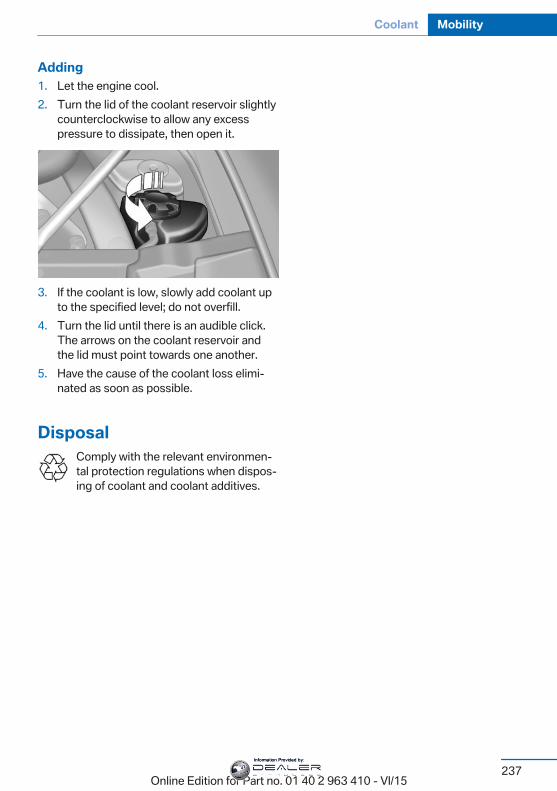
Adding1. Let the engine cool.2. Turn the lid of the coolant reservoir slightly
counterclockwise to allow any excesspressure to dissipate, then open it.
3. If the coolant is low, slowly add coolant upto the specified level; do not overfill.
4. Turn the lid until there is an audible click.The arrows on the coolant reservoir andthe lid must point towards one another.
5. Have the cause of the coolant loss elimi‐nated as soon as possible.
DisposalComply with the relevant environmen‐tal protection regulations when dispos‐ing of coolant and coolant additives.
Seite 237
Coolant Mobility
237Online Edition for Part no. 01 40 2 963 410 - VI/15
Information Provided by:
MaintenanceVehicle features and optionsThis chapter describes all standard, country-specific and optional features offered with theseries. It also describes features that are notnecessarily available in your car, e. g., due tothe selected options or country versions. Thisalso applies to safety-related functions andsystems. The respectively applicable countryprovisions must be observed when using therespective features and systems.
BMW maintenance systemThe maintenance system indicates requiredmaintenance measures, and thereby providessupport in maintaining road safety and the op‐erational reliability of the vehicle.In some cases scopes and intervals may varyaccording to the country-specific version. Re‐placement work, spare parts, fuels and lubri‐cants and wear materials are calculated sepa‐rately. Further information is available from adealer’s service center or another qualifiedservice center or repair shop.
Condition Based ServiceCBSSensors and special algorithms take into ac‐count the driving conditions of your vehicle.Based on this, Condition Based Service recog‐nizes the maintenance requirements.The system makes it possible to adapt theamount of maintenance corresponding to youruser profile.Detailed information on service requirements,refer to page 95, can be displayed on the Con‐trol Display.
Service data in the remote controlInformation on the required maintenance iscontinuously stored in the remote control. Thedealer’s service center can read this data outand suggest an optimized maintenance scopefor your vehicle.Therefore, hand the service advisor the remotecontrol with which the vehicle was driven mostrecently.
Storage periodsStorage periods during which the vehicle bat‐tery was disconnected are not taken into ac‐count.If this occurs, have a dealer's service center oranother qualified service center or repair shopupdate the time-dependent maintenance pro‐cedures, such as checking brake fluid and, ifnecessary, changing the engine oil and the mi‐crofilter/activated-charcoal filter.
Service and WarrantyInformation Booklet for USmodels and Warranty andService Guide Booklet forCanadian modelsPlease consult your Service and Warranty In‐formation Booklet for US models and Warrantyand Service Guide Booklet for Canadian mod‐els for additional information on service re‐quirements.The manufacturer of your vehicle recommendsthat maintenance and repair be performed by adealer’s service center or another qualifiedservice center or repair shop. Records of regu‐lar maintenance and repair work should be re‐tained.
Seite 238
Mobility Maintenance
238Online Edition for Part no. 01 40 2 963 410 - VI/15
Information Provided by:
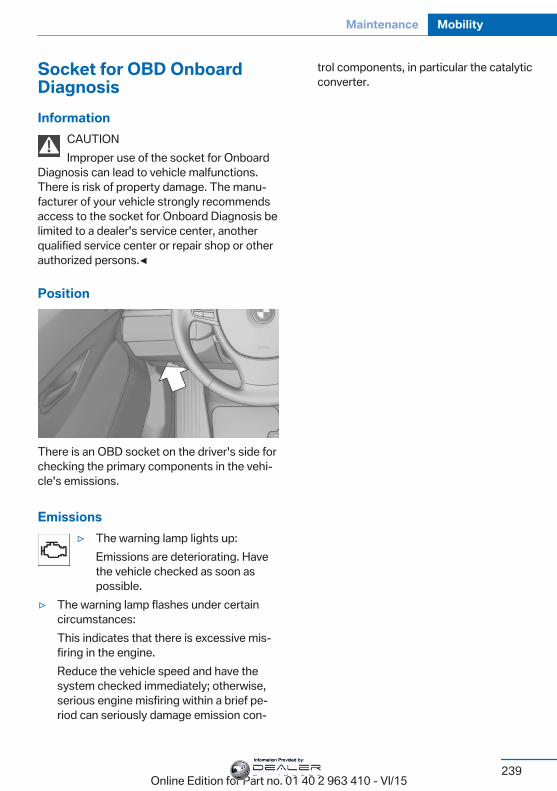
Socket for OBD OnboardDiagnosisInformation
CAUTIONImproper use of the socket for Onboard
Diagnosis can lead to vehicle malfunctions.There is risk of property damage. The manu‐facturer of your vehicle strongly recommendsaccess to the socket for Onboard Diagnosis belimited to a dealer's service center, anotherqualified service center or repair shop or otherauthorized persons.◀
Position
There is an OBD socket on the driver's side forchecking the primary components in the vehi‐cle's emissions.
Emissions▷ The warning lamp lights up:
Emissions are deteriorating. Havethe vehicle checked as soon aspossible.
▷ The warning lamp flashes under certaincircumstances:This indicates that there is excessive mis‐firing in the engine.Reduce the vehicle speed and have thesystem checked immediately; otherwise,serious engine misfiring within a brief pe‐riod can seriously damage emission con‐
trol components, in particular the catalyticconverter.
Seite 239
Maintenance Mobility
239Online Edition for Part no. 01 40 2 963 410 - VI/15
Information Provided by:
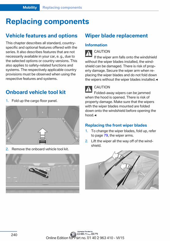
Replacing componentsVehicle features and optionsThis chapter describes all standard, country-specific and optional features offered with theseries. It also describes features that are notnecessarily available in your car, e. g., due tothe selected options or country versions. Thisalso applies to safety-related functions andsystems. The respectively applicable countryprovisions must be observed when using therespective features and systems.
Onboard vehicle tool kit1. Fold up the cargo floor panel.
2. Remove the onboard vehicle tool kit.
Wiper blade replacementInformation
CAUTIONIf the wiper arm falls onto the windshield
without the wiper blades installed, the wind‐shield can be damaged. There is risk of prop‐erty damage. Secure the wiper arm when re‐placing the wiper blades and do not fold downthe wipers without the wiper blades installed.◀
CAUTIONFolded-away wipers can be jammed
when the hood is opened. There is risk ofproperty damage. Make sure that the wiperswith the wiper blades mounted are foldeddown onto the windshield before opening thehood.◀
Replacing the front wiper blades1. To change the wiper blades, fold up, refer
to page 79, the wiper arms.2. Lift the wiper all the way off of the wind‐
shield.
Seite 240
Mobility Replacing components
240Online Edition for Part no. 01 40 2 963 410 - VI/15
Information Provided by:
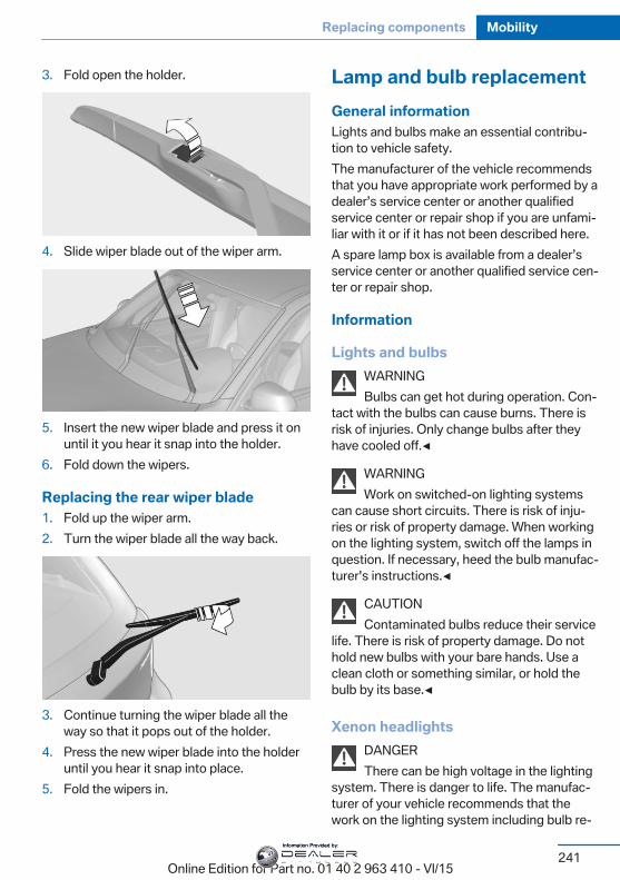
3. Fold open the holder.
4. Slide wiper blade out of the wiper arm.
5. Insert the new wiper blade and press it onuntil it you hear it snap into the holder.
6. Fold down the wipers.
Replacing the rear wiper blade1. Fold up the wiper arm.2. Turn the wiper blade all the way back.
3. Continue turning the wiper blade all theway so that it pops out of the holder.
4. Press the new wiper blade into the holderuntil you hear it snap into place.
5. Fold the wipers in.
Lamp and bulb replacementGeneral informationLights and bulbs make an essential contribu‐tion to vehicle safety.The manufacturer of the vehicle recommendsthat you have appropriate work performed by adealer’s service center or another qualifiedservice center or repair shop if you are unfami‐liar with it or if it has not been described here.A spare lamp box is available from a dealer’sservice center or another qualified service cen‐ter or repair shop.
Information
Lights and bulbsWARNINGBulbs can get hot during operation. Con‐
tact with the bulbs can cause burns. There isrisk of injuries. Only change bulbs after theyhave cooled off.◀
WARNINGWork on switched-on lighting systems
can cause short circuits. There is risk of inju‐ries or risk of property damage. When workingon the lighting system, switch off the lamps inquestion. If necessary, heed the bulb manufac‐turer's instructions.◀
CAUTIONContaminated bulbs reduce their service
life. There is risk of property damage. Do nothold new bulbs with your bare hands. Use aclean cloth or something similar, or hold thebulb by its base.◀
Xenon headlightsDANGERThere can be high voltage in the lighting
system. There is danger to life. The manufac‐turer of your vehicle recommends that thework on the lighting system including bulb re‐
Seite 241
Replacing components Mobility
241Online Edition for Part no. 01 40 2 963 410 - VI/15
Information Provided by:
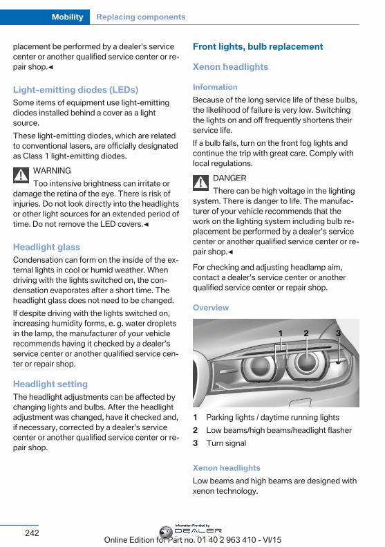
placement be performed by a dealer’s servicecenter or another qualified service center or re‐pair shop.◀
Light-emitting diodes (LEDs)Some items of equipment use light-emittingdiodes installed behind a cover as a lightsource.These light-emitting diodes, which are relatedto conventional lasers, are officially designatedas Class 1 light-emitting diodes.
WARNINGToo intensive brightness can irritate or
damage the retina of the eye. There is risk ofinjuries. Do not look directly into the headlightsor other light sources for an extended period oftime. Do not remove the LED covers.◀
Headlight glassCondensation can form on the inside of the ex‐ternal lights in cool or humid weather. Whendriving with the lights switched on, the con‐densation evaporates after a short time. Theheadlight glass does not need to be changed.If despite driving with the lights switched on,increasing humidity forms, e. g. water dropletsin the lamp, the manufacturer of your vehiclerecommends having it checked by a dealer’sservice center or another qualified service cen‐ter or repair shop.
Headlight settingThe headlight adjustments can be affected bychanging lights and bulbs. After the headlightadjustment was changed, have it checked and,if necessary, corrected by a dealer’s servicecenter or another qualified service center or re‐pair shop.
Front lights, bulb replacement
Xenon headlights
InformationBecause of the long service life of these bulbs,the likelihood of failure is very low. Switchingthe lights on and off frequently shortens theirservice life.If a bulb fails, turn on the front fog lights andcontinue the trip with great care. Comply withlocal regulations.
DANGERThere can be high voltage in the lighting
system. There is danger to life. The manufac‐turer of your vehicle recommends that thework on the lighting system including bulb re‐placement be performed by a dealer’s servicecenter or another qualified service center or re‐pair shop.◀
For checking and adjusting headlamp aim,contact a dealer’s service center or anotherqualified service center or repair shop.
Overview
1 Parking lights / daytime running lights2 Low beams/high beams/headlight flasher3 Turn signal
Xenon headlightsLow beams and high beams are designed withxenon technology.
Seite 242
Mobility Replacing components
242Online Edition for Part no. 01 40 2 963 410 - VI/15
Information Provided by:
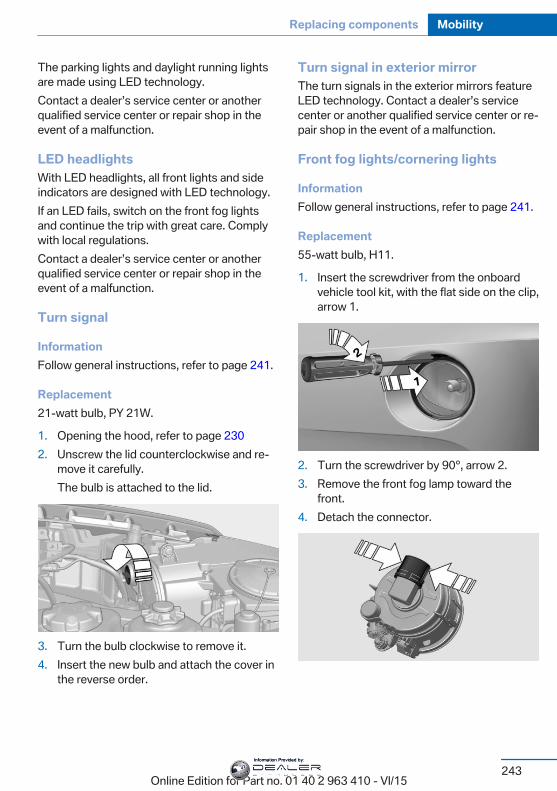
The parking lights and daylight running lightsare made using LED technology.Contact a dealer’s service center or anotherqualified service center or repair shop in theevent of a malfunction.
LED headlightsWith LED headlights, all front lights and sideindicators are designed with LED technology.If an LED fails, switch on the front fog lightsand continue the trip with great care. Complywith local regulations.Contact a dealer’s service center or anotherqualified service center or repair shop in theevent of a malfunction.
Turn signal
InformationFollow general instructions, refer to page 241.
Replacement21-watt bulb, PY 21W.
1. Opening the hood, refer to page 2302. Unscrew the lid counterclockwise and re‐
move it carefully.The bulb is attached to the lid.
3. Turn the bulb clockwise to remove it.4. Insert the new bulb and attach the cover in
the reverse order.
Turn signal in exterior mirrorThe turn signals in the exterior mirrors featureLED technology. Contact a dealer’s servicecenter or another qualified service center or re‐pair shop in the event of a malfunction.
Front fog lights/cornering lights
InformationFollow general instructions, refer to page 241.
Replacement55-watt bulb, H11.
1. Insert the screwdriver from the onboardvehicle tool kit, with the flat side on the clip,arrow 1.
2. Turn the screwdriver by 90°, arrow 2.3. Remove the front fog lamp toward the
front.4. Detach the connector.
Seite 243
Replacing components Mobility
243Online Edition for Part no. 01 40 2 963 410 - VI/15
Information Provided by:
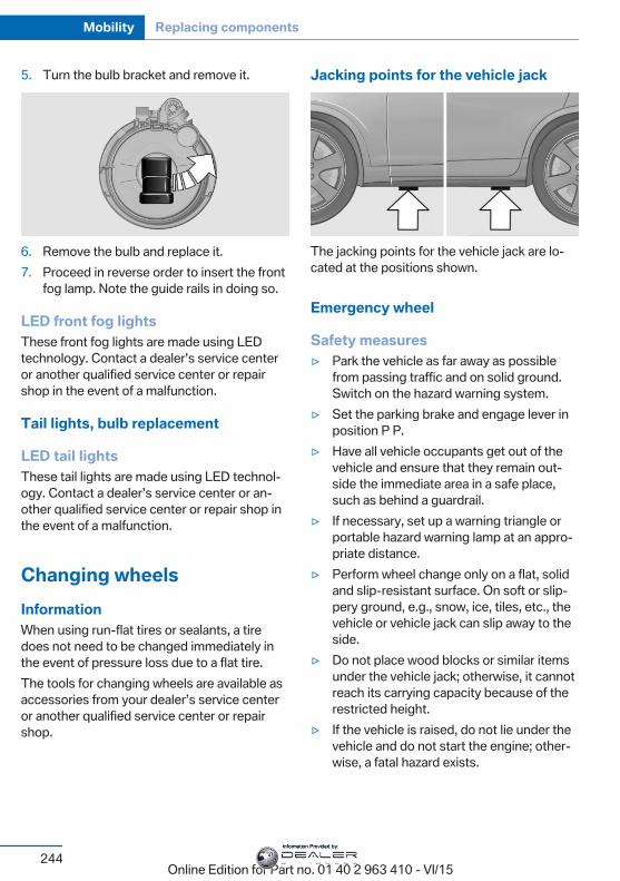
5. Turn the bulb bracket and remove it.
6. Remove the bulb and replace it.7. Proceed in reverse order to insert the front
fog lamp. Note the guide rails in doing so.
LED front fog lightsThese front fog lights are made using LEDtechnology. Contact a dealer’s service centeror another qualified service center or repairshop in the event of a malfunction.
Tail lights, bulb replacement
LED tail lightsThese tail lights are made using LED technol‐ogy. Contact a dealer’s service center or an‐other qualified service center or repair shop inthe event of a malfunction.
Changing wheelsInformationWhen using run-flat tires or sealants, a tiredoes not need to be changed immediately inthe event of pressure loss due to a flat tire.The tools for changing wheels are available asaccessories from your dealer’s service centeror another qualified service center or repairshop.
Jacking points for the vehicle jack
The jacking points for the vehicle jack are lo‐cated at the positions shown.
Emergency wheel
Safety measures▷ Park the vehicle as far away as possible
from passing traffic and on solid ground.Switch on the hazard warning system.
▷ Set the parking brake and engage lever inposition P P.
▷ Have all vehicle occupants get out of thevehicle and ensure that they remain out‐side the immediate area in a safe place,such as behind a guardrail.
▷ If necessary, set up a warning triangle orportable hazard warning lamp at an appro‐priate distance.
▷ Perform wheel change only on a flat, solidand slip-resistant surface. On soft or slip‐pery ground, e.g., snow, ice, tiles, etc., thevehicle or vehicle jack can slip away to theside.
▷ Do not place wood blocks or similar itemsunder the vehicle jack; otherwise, it cannotreach its carrying capacity because of therestricted height.
▷ If the vehicle is raised, do not lie under thevehicle and do not start the engine; other‐wise, a fatal hazard exists.
Seite 244
Mobility Replacing components
244Online Edition for Part no. 01 40 2 963 410 - VI/15
Information Provided by:
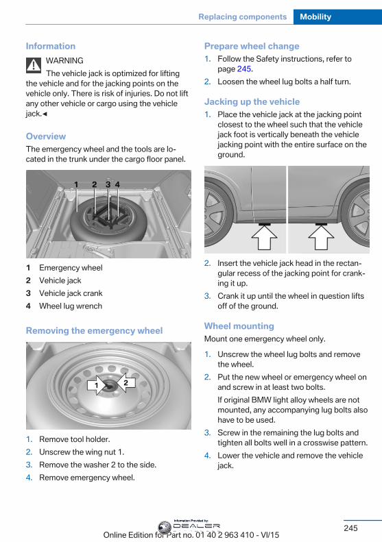
InformationWARNINGThe vehicle jack is optimized for lifting
the vehicle and for the jacking points on thevehicle only. There is risk of injuries. Do not liftany other vehicle or cargo using the vehiclejack.◀
OverviewThe emergency wheel and the tools are lo‐cated in the trunk under the cargo floor panel.
1 Emergency wheel2 Vehicle jack3 Vehicle jack crank4 Wheel lug wrench
Removing the emergency wheel
1. Remove tool holder.2. Unscrew the wing nut 1.3. Remove the washer 2 to the side.4. Remove emergency wheel.
Prepare wheel change1. Follow the Safety instructions, refer to
page 245.2. Loosen the wheel lug bolts a half turn.
Jacking up the vehicle1. Place the vehicle jack at the jacking point
closest to the wheel such that the vehiclejack foot is vertically beneath the vehiclejacking point with the entire surface on theground.
2. Insert the vehicle jack head in the rectan‐gular recess of the jacking point for crank‐ing it up.
3. Crank it up until the wheel in question liftsoff of the ground.
Wheel mountingMount one emergency wheel only.
1. Unscrew the wheel lug bolts and removethe wheel.
2. Put the new wheel or emergency wheel onand screw in at least two bolts.If original BMW light alloy wheels are notmounted, any accompanying lug bolts alsohave to be used.
3. Screw in the remaining the lug bolts andtighten all bolts well in a crosswise pattern.
4. Lower the vehicle and remove the vehiclejack.
Seite 245
Replacing components Mobility
245Online Edition for Part no. 01 40 2 963 410 - VI/15
Information Provided by:
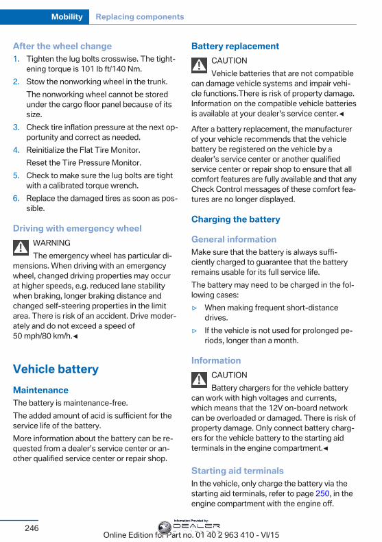
After the wheel change1. Tighten the lug bolts crosswise. The tight‐
ening torque is 101 lb ft/140 Nm.2. Stow the nonworking wheel in the trunk.
The nonworking wheel cannot be storedunder the cargo floor panel because of itssize.
3. Check tire inflation pressure at the next op‐portunity and correct as needed.
4. Reinitialize the Flat Tire Monitor.Reset the Tire Pressure Monitor.
5. Check to make sure the lug bolts are tightwith a calibrated torque wrench.
6. Replace the damaged tires as soon as pos‐sible.
Driving with emergency wheelWARNINGThe emergency wheel has particular di‐
mensions. When driving with an emergencywheel, changed driving properties may occurat higher speeds, e.g. reduced lane stabilitywhen braking, longer braking distance andchanged self-steering properties in the limitarea. There is risk of an accident. Drive moder‐ately and do not exceed a speed of50 mph/80 km/h.◀
Vehicle batteryMaintenanceThe battery is maintenance-free.The added amount of acid is sufficient for theservice life of the battery.More information about the battery can be re‐quested from a dealer’s service center or an‐other qualified service center or repair shop.
Battery replacementCAUTIONVehicle batteries that are not compatible
can damage vehicle systems and impair vehi‐cle functions.There is risk of property damage.Information on the compatible vehicle batteriesis available at your dealer's service center.◀
After a battery replacement, the manufacturerof your vehicle recommends that the vehiclebattery be registered on the vehicle by adealer’s service center or another qualifiedservice center or repair shop to ensure that allcomfort features are fully available and that anyCheck Control messages of these comfort fea‐tures are no longer displayed.
Charging the battery
General informationMake sure that the battery is always suffi‐ciently charged to guarantee that the batteryremains usable for its full service life.The battery may need to be charged in the fol‐lowing cases:▷ When making frequent short-distance
drives.▷ If the vehicle is not used for prolonged pe‐
riods, longer than a month.
InformationCAUTIONBattery chargers for the vehicle battery
can work with high voltages and currents,which means that the 12V on-board networkcan be overloaded or damaged. There is risk ofproperty damage. Only connect battery charg‐ers for the vehicle battery to the starting aidterminals in the engine compartment.◀
Starting aid terminalsIn the vehicle, only charge the battery via thestarting aid terminals, refer to page 250, in theengine compartment with the engine off.
Seite 246
Mobility Replacing components
246Online Edition for Part no. 01 40 2 963 410 - VI/15
Information Provided by:
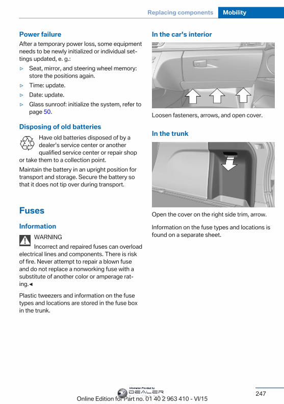
Power failureAfter a temporary power loss, some equipmentneeds to be newly initialized or individual set‐tings updated, e. g.:▷ Seat, mirror, and steering wheel memory:
store the positions again.▷ Time: update.▷ Date: update.▷ Glass sunroof: initialize the system, refer to
page 50.
Disposing of old batteriesHave old batteries disposed of by adealer’s service center or anotherqualified service center or repair shop
or take them to a collection point.Maintain the battery in an upright position fortransport and storage. Secure the battery sothat it does not tip over during transport.
FusesInformation
WARNINGIncorrect and repaired fuses can overload
electrical lines and components. There is riskof fire. Never attempt to repair a blown fuseand do not replace a nonworking fuse with asubstitute of another color or amperage rat‐ing.◀
Plastic tweezers and information on the fusetypes and locations are stored in the fuse boxin the trunk.
In the car's interior
Loosen fasteners, arrows, and open cover.
In the trunk
Open the cover on the right side trim, arrow.
Information on the fuse types and locations isfound on a separate sheet.
Seite 247
Replacing components Mobility
247Online Edition for Part no. 01 40 2 963 410 - VI/15
Information Provided by:
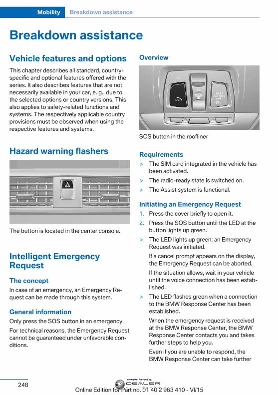
Breakdown assistanceVehicle features and optionsThis chapter describes all standard, country-specific and optional features offered with theseries. It also describes features that are notnecessarily available in your car, e. g., due tothe selected options or country versions. Thisalso applies to safety-related functions andsystems. The respectively applicable countryprovisions must be observed when using therespective features and systems.
Hazard warning flashers
The button is located in the center console.
Intelligent EmergencyRequestThe conceptIn case of an emergency, an Emergency Re‐quest can be made through this system.
General informationOnly press the SOS button in an emergency.For technical reasons, the Emergency Requestcannot be guaranteed under unfavorable con‐ditions.
Overview
SOS button in the roofliner
Requirements▷ The SIM card integrated in the vehicle has
been activated.▷ The radio-ready state is switched on.▷ The Assist system is functional.
Initiating an Emergency Request1. Press the cover briefly to open it.2. Press the SOS button until the LED at the
button lights up green.▷ The LED lights up green: an Emergency
Request was initiated.If a cancel prompt appears on the display,the Emergency Request can be aborted.If the situation allows, wait in your vehicleuntil the voice connection has been estab‐lished.
▷ The LED flashes green when a connectionto the BMW Response Center has beenestablished.When the emergency request is receivedat the BMW Response Center, the BMWResponse Center contacts you and takesfurther steps to help you.Even if you are unable to respond, theBMW Response Center can take further
Seite 248
Mobility Breakdown assistance
248Online Edition for Part no. 01 40 2 963 410 - VI/15
Information Provided by:
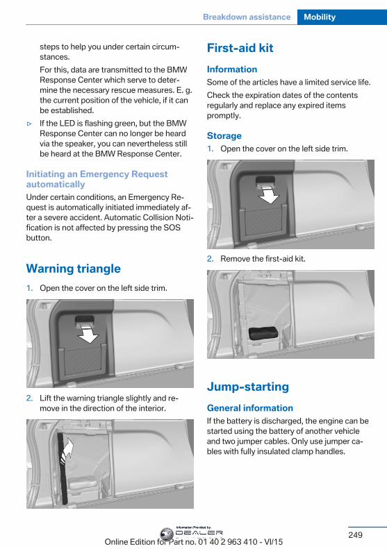
steps to help you under certain circum‐stances.For this, data are transmitted to the BMWResponse Center which serve to deter‐mine the necessary rescue measures. E. g.the current position of the vehicle, if it canbe established.
▷ If the LED is flashing green, but the BMWResponse Center can no longer be heardvia the speaker, you can nevertheless stillbe heard at the BMW Response Center.
Initiating an Emergency RequestautomaticallyUnder certain conditions, an Emergency Re‐quest is automatically initiated immediately af‐ter a severe accident. Automatic Collision Noti‐fication is not affected by pressing the SOSbutton.
Warning triangle1. Open the cover on the left side trim.
2. Lift the warning triangle slightly and re‐move in the direction of the interior.
First-aid kitInformationSome of the articles have a limited service life.Check the expiration dates of the contentsregularly and replace any expired itemspromptly.
Storage1. Open the cover on the left side trim.
2. Remove the first-aid kit.
Jump-startingGeneral informationIf the battery is discharged, the engine can bestarted using the battery of another vehicleand two jumper cables. Only use jumper ca‐bles with fully insulated clamp handles.
Seite 249
Breakdown assistance Mobility
249Online Edition for Part no. 01 40 2 963 410 - VI/15
Information Provided by:
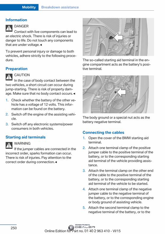
InformationDANGERContact with live components can lead to
an electric shock. There is risk of injuries ordanger to life. Do not touch any componentsthat are under voltage.◀
To prevent personal injury or damage to bothvehicles, adhere strictly to the following proce‐dure.
PreparationCAUTIONIn the case of body contact between the
two vehicles, a short circuit can occur duringjump-starting. There is risk of property dam‐age. Make sure that no body contact occurs.◀
1. Check whether the battery of the other ve‐hicle has a voltage of 12 volts. This infor‐mation can be found on the battery.
2. Switch off the engine of the assisting vehi‐cle.
3. Switch off any electronic systems/powerconsumers in both vehicles.
Starting aid terminalsWARNINGIf the jumper cables are connected in the
incorrect order, sparks formation can occur.There is risk of injuries. Pay attention to thecorrect order during connection.◀
The so-called starting aid terminal in the en‐gine compartment acts as the battery's posi‐tive terminal.
The body ground or a special nut acts as thebattery negative terminal.
Connecting the cables1. Open the cover of the BMW starting aid
terminal.2. Attach one terminal clamp of the positive
jumper cable to the positive terminal of thebattery, or to the corresponding startingaid terminal of the vehicle providing assis‐tance.
3. Attach the terminal clamp on the other endof the cable to the positive terminal of thebattery, or to the corresponding startingaid terminal of the vehicle to be started.
4. Attach one terminal clamp of the negativejumper cable to the negative terminal ofthe battery, or to the corresponding engineor body ground of assisting vehicle.
5. Attach the second terminal clamp to thenegative terminal of the battery, or to the
Seite 250
Mobility Breakdown assistance
250Online Edition for Part no. 01 40 2 963 410 - VI/15
Information Provided by:
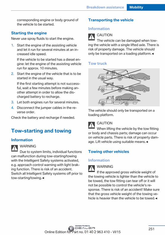
corresponding engine or body ground ofthe vehicle to be started.
Starting the engineNever use spray fluids to start the engine.
1. Start the engine of the assisting vehicleand let it run for several minutes at an in‐creased idle speed.If the vehicle to be started has a diesel en‐gine: let the engine of the assisting vehiclerun for approx. 10 minutes.
2. Start the engine of the vehicle that is to bestarted in the usual way.If the first starting attempt is not success‐ful, wait a few minutes before making an‐other attempt in order to allow the dis‐charged battery to recharge.
3. Let both engines run for several minutes.4. Disconnect the jumper cables in the re‐
verse order.Check the battery and recharge if needed.
Tow-starting and towingInformation
WARNINGDue to system limits, individual functions
can malfunction during tow-starting/towingwith the Intelligent Safety systems activated,e.g. approach control warning with light brak‐ing function. There is risk of an accident.Switch all Intelligent Safety systems off prior totow-starting/towing.◀
Transporting the vehicle
InformationCAUTIONThe vehicle can be damaged when tow‐
ing the vehicle with a single lifted axle. There isrisk of property damage. The vehicle shouldonly be transported on a loading platform.◀
Tow truck
The vehicle should only be transported on aloading platform.
CAUTIONWhen lifting the vehicle by the tow fitting
or body and chassis parts; damage can occuron vehicle parts. There is risk of property dam‐age. Lift vehicle using suitable means.◀
Towing other vehicles
InformationWARNINGIf the approved gross vehicle weight of
the towing vehicle is lighter than the vehicle tobe towed, the tow fitting can tear off or it willnot be possible to control the vehicle's re‐sponse. There is risk of an accident! Make surethat the gross vehicle weight of the towing ve‐hicle is heavier than the vehicle to be towed.◀
Seite 251
Breakdown assistance Mobility
251Online Edition for Part no. 01 40 2 963 410 - VI/15
Information Provided by:
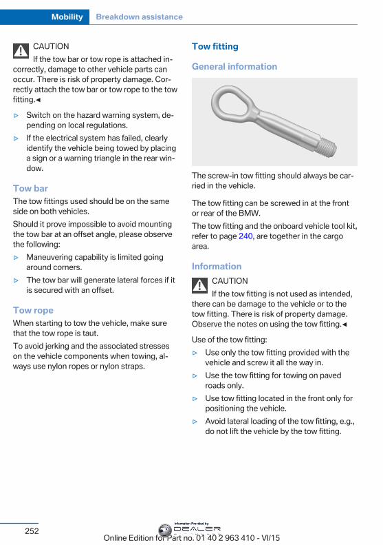
CAUTIONIf the tow bar or tow rope is attached in‐
correctly, damage to other vehicle parts canoccur. There is risk of property damage. Cor‐rectly attach the tow bar or tow rope to the towfitting.◀
▷ Switch on the hazard warning system, de‐pending on local regulations.
▷ If the electrical system has failed, clearlyidentify the vehicle being towed by placinga sign or a warning triangle in the rear win‐dow.
Tow barThe tow fittings used should be on the sameside on both vehicles.Should it prove impossible to avoid mountingthe tow bar at an offset angle, please observethe following:▷ Maneuvering capability is limited going
around corners.▷ The tow bar will generate lateral forces if it
is secured with an offset.
Tow ropeWhen starting to tow the vehicle, make surethat the tow rope is taut.To avoid jerking and the associated stresseson the vehicle components when towing, al‐ways use nylon ropes or nylon straps.
Tow fitting
General information
The screw-in tow fitting should always be car‐ried in the vehicle.
The tow fitting can be screwed in at the frontor rear of the BMW.The tow fitting and the onboard vehicle tool kit,refer to page 240, are together in the cargoarea.
InformationCAUTIONIf the tow fitting is not used as intended,
there can be damage to the vehicle or to thetow fitting. There is risk of property damage.Observe the notes on using the tow fitting.◀
Use of the tow fitting:▷ Use only the tow fitting provided with the
vehicle and screw it all the way in.▷ Use the tow fitting for towing on paved
roads only.▷ Use tow fitting located in the front only for
positioning the vehicle.▷ Avoid lateral loading of the tow fitting, e.g.,
do not lift the vehicle by the tow fitting.
Seite 252
Mobility Breakdown assistance
252Online Edition for Part no. 01 40 2 963 410 - VI/15
Information Provided by:
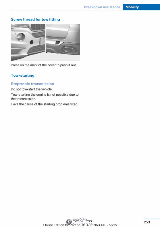
Screw thread for tow fitting
Press on the mark of the cover to push it out.
Tow-starting
Steptronic transmissionDo not tow-start the vehicle.Tow-starting the engine is not possible due tothe transmission.Have the cause of the starting problems fixed.
Seite 253
Breakdown assistance Mobility
253Online Edition for Part no. 01 40 2 963 410 - VI/15
Information Provided by:
CareVehicle features and optionsThis chapter describes all standard, country-specific and optional features offered with theseries. It also describes features that are notnecessarily available in your car, e. g., due tothe selected options or country versions. Thisalso applies to safety-related functions andsystems. The respectively applicable countryprovisions must be observed when using therespective features and systems.
Car washesGeneral informationRegularly remove foreign objects such asleaves in the area below the windshield whenthe hood is raised.Wash your vehicle frequently, particularly inwinter. Intense soiling and road salt can dam‐age the vehicle.
Steam blaster and high-pressurewasher
InformationCAUTIONWhen cleaning with high-pressure wash‐
ers, components can be damaged due to thepressure or temperatures being too high.There is risk of property damage. Maintain suf‐ficient distance and do not spray too long con‐tinuously. Follow the user's manual for thehigh-pressure washer.◀
Distances and temperature▷ Maximum temperature: 140 ℉/60 ℃.▷ Minimum distance from sensors, cameras,
seals: 12 in/30 cm.
▷ Minimum distance from glass sunroof:31.5 inches/80 cm.
Automatic car washes
InformationNote the following:▷ Give preference to cloth car washes or
those that use soft brushes in order toavoid paint damage.
▷ Make sure that the wheels and tires are notdamaged by the transport mechanisms.
▷ Fold in the exterior mirrors; otherwise, theymay be damaged, depending on the widthof the vehicle.
▷ Deactivate the rain sensor, refer topage 78, to avoid unintentional wiper acti‐vation.
▷ In some cases, an unintentional alarm canbe triggered by the interior motion sensorof the alarm system. Follow the instruc‐tions on avoiding an unintentional alarm,refer to page 47.
CAUTIONToo high guide rails in car washes can
damage body parts. There is risk of propertydamage. Avoid car washes with guide railshigher than 4 in/10 cm.◀
Different types of tiresCAUTIONThe vehicle might be too large for the car
wash. There is risk of property damage. Beforedriving into the car wash, make sure that thevehicle is not too large.◀
Seite 254
Mobility Care
254Online Edition for Part no. 01 40 2 963 410 - VI/15
Information Provided by:
Before driving into a car washIn order to ensure that the vehicle can roll in acar wash, take the following steps:
1. Drive into the car wash.2. Engage selector lever position N.3. Deactivating Automatic Hold, refer to
page 75.4. Release the parking brake.5. Switch the engine off.
In this way, the ignition remains switchedon, and a Check-Control message is dis‐played.
CAUTIONSelector lever position P is automati‐
cally engaged when the ignition isswitched off. There is risk of property dam‐age. Do not switch ignition off in carwashes.◀
The vehicle cannot be locked from the outsidewhen in selector lever position N. A signalsounds when an attempt is made to lock thevehicle.To start the engine:
1. Depress the brake pedal.2. Press the Start/Stop button.Pressing the Start/Stop button without step‐ping on the brake turns the ignition off.
Selector lever positionSelector lever position P is engaged automati‐cally:▷ When the ignition is switched off.▷ After approx. 15 minutes.
Headlights▷ Do not rub dry and do not use abrasive or
acidic cleansers.▷ Soak areas that have been dirtied e. g.,
from insects, with shampoo and wash offwith water.
▷ Thaw ice with de-icing spray; do not use anice scraper.
After washing the vehicleAfter washing the vehicle, apply the brakesbriefly to dry them; otherwise, braking actioncan be reduced and corrosion of the brakediscs can occur.Completely remove all residues on the win‐dows, to minimize loss of visibility due tosmearing and to reduce wiper noises andwiper blade wear.
Vehicle careCar care productsThe manufacturer of your vehicle recommendsusing car care and cleaning products fromBMW.
WARNINGCleansers can contain substances that
are dangerous and harmful to your health.There is risk of injuries. When cleaning the in‐terior, open the doors or windows. Only useproducts intended for cleaning vehicles. Fol‐low the instructions on the container.◀
Vehicle paintRegular care contributes to driving safety andvalue retention. Environmental influences inareas with elevated air pollution or natural con‐taminants, such as tree resin or pollen can af‐fect the vehicle's paintwork. Tailor the fre‐quency and extent of your car care to theseinfluences.Aggressive substances such as spilled fuel, oil,grease or bird droppings, must be removed im‐mediately to prevent the finish from being al‐tered or discolored.
Leather careRemove dust from the leather often, using acloth or vacuum cleaner.
Seite 255
Care Mobility
255Online Edition for Part no. 01 40 2 963 410 - VI/15
Information Provided by:
Otherwise, particles of dust and road grimechafe in pores and folds, and lead to increasedwear and premature degradation of the leathersurface.To guard against discoloration, such as fromclothing, provide leather care roughly everytwo months.Clean light-colored leather more frequently be‐cause soiling on such surfaces is substantiallymore visible.Use leather care products; otherwise, dirt andgrease will gradually break down the protectivelayer of the leather surface.Suitable care products are available from adealer’s service center or another qualifiedservice center or repair shop.
Upholstery material careVacuum regularly with a vacuum cleaner.If upholstery is very dirty, e.g., with beveragestains, use a soft sponge or microfiber clothwith a suitable interior cleaner.Clean the upholstery down to the seams usinglarge sweeping motions. Avoid rubbing thematerial vigorously.
CAUTIONOpen Velcro® fasteners on articles of
clothing can damage the seat covers. There isrisk of property damage. Ensure that any Vel‐cro® fasteners are closed.◀
Caring for special components
Light-alloy wheelsWhen cleaning the vehicle, use only neutralwheel cleaners having a pH value from 5 to 9.Do not use abrasive cleaning agents or steamjets above 140 ℉/60 ℃. Follow the manufac‐turer's instructions.Aggressive, acidic or alkaline cleaning agentscan destroy the protective layer of adjacentcomponents, such as the brake disk.
Chrome surfacesCarefully clean components such as the radia‐tor grille or door handles with an ample supplyof water, possibly with shampoo added, partic‐ularly when they have been exposed to roadsalt.
Rubber componentsEnvironmental influences can cause surfacesoiling of rubber parts and a loss of gloss. Forcleaning, use only water and suitable careproducts, the manufacturer of your vehicle rec‐ommends original BMW care products.Treat especially worn rubber parts with rubbercare agents at regular intervals. When cleaningrubber seals, do not use any silicon-containingcar care products in order to avoid damage ornoises.
Fine wood partsClean fine wood facing and fine wood compo‐nents only with a moist rag. Then dry with asoft cloth.
Plastic componentsThese include:▷ Imitation leather surfaces.▷ Roofliner.▷ Lamp lenses.▷ Instrument cluster cover.▷ Matt black spray-coated components.▷ Painted parts in the interior.Clean with a microfiber cloth.Dampen cloth lightly with water.Do not soak the roofliner.
CAUTIONCleansers that contain alcohol or sol‐
vents, such as lacquer thinners, heavy-dutygrease removers, fuel, or such, can damageplastic parts. There is risk of property damage.Clean with a microfiber cloth. Dampen clothlightly with water.◀
Seite 256
Mobility Care
256Online Edition for Part no. 01 40 2 963 410 - VI/15
Information Provided by:
Safety beltsDirty belt straps impede the reeling action andthus have a negative impact on safety.
WARNINGChemical cleansers can destroy the
safety belt webbing. Missing protective effectof the safety belts. There is risk of injuries ordanger to life. Use only a mild soapy solutionfor cleaning the safety belts.◀
Use only a mild soapy solution, with the safetybelts clipped into their buckles.Do not allow the switchs to retract the safetybelts until they are dry.
Carpets and floor matsWARNINGObjects in the driver's floor area can limit
the pedal distance or block a depressed pedal.There is risk of an accident. Stow objects inthe vehicle such that they are secured andcannot enter into the driver's floor area. Usefloor mats that are suitable for the vehicle andcan be safely attached to the floor. Do not useloose floor mats and do not layer several floormats. Make sure that there is sufficient clear‐ance for the pedals. Ensure that the floor matsare securely fastened again after they were re‐moved, e.g. for cleaning.◀
Floor mats can be removed from the car's inte‐rior for cleaning.If the floor carpets are very dirty, clean with amicrofiber cloth and water or a textile cleaner.To prevent matting of the carpet, rub back andforth in the direction of travel only.
Sensor/camera lensesTo clean sensors and camera lenses, use acloth moistened with a small amount of glassdetergent.
Displays/Screens/protective glass ofthe Head-up Display
CAUTIONChemical cleansers, moisture or fluids of
any kind can damage the surface of displaysand screens. There is risk of property damage.Clean with a clean, antistatic microfiber cloth.◀
CAUTIONThe surface of displays can be damaged
with improper cleaning. There is risk of prop‐erty damage. Avoid pressure that is too highand do not use any scratching materials.◀
Clean with a clean, antistatic microfiber cloth.Clean the protective glass of the Head-up Dis‐play using a microfiber cloth and commerciallyavailable dish-washing soap.
Long-termWhen the vehicle is shut down for longer thanthree months, special measures must betaken. Further information is available from adealer’s service center or another qualifiedservice center or repair shop.
Seite 257
Care Mobility
257Online Edition for Part no. 01 40 2 963 410 - VI/15
Information Provided by:
Online Edition for Part no. 01 40 2 963 410 - VI/15
Information Provided by:
ReferenceThis chapter contains the technical data and an
index that will quickly take you to the informationyou need.
Online Edition for Part no. 01 40 2 963 410 - VI/15
Information Provided by:
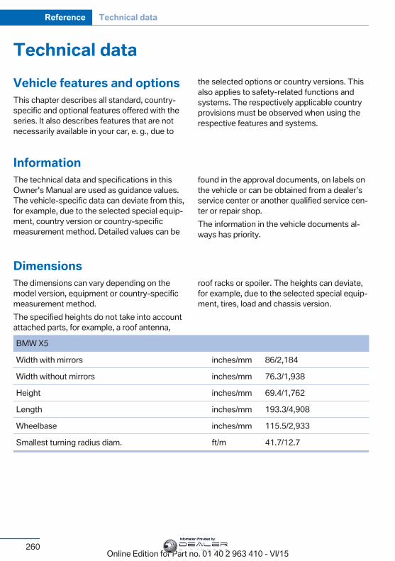
Technical dataVehicle features and optionsThis chapter describes all standard, country-specific and optional features offered with theseries. It also describes features that are notnecessarily available in your car, e. g., due to
the selected options or country versions. Thisalso applies to safety-related functions andsystems. The respectively applicable countryprovisions must be observed when using therespective features and systems.
InformationThe technical data and specifications in thisOwner's Manual are used as guidance values.The vehicle-specific data can deviate from this,for example, due to the selected special equip‐ment, country version or country-specificmeasurement method. Detailed values can be
found in the approval documents, on labels onthe vehicle or can be obtained from a dealer’sservice center or another qualified service cen‐ter or repair shop.The information in the vehicle documents al‐ways has priority.
DimensionsThe dimensions can vary depending on themodel version, equipment or country-specificmeasurement method.The specified heights do not take into accountattached parts, for example, a roof antenna,
roof racks or spoiler. The heights can deviate,for example, due to the selected special equip‐ment, tires, load and chassis version.
Seite 260
Reference Technical data
260Online Edition for Part no. 01 40 2 963 410 - VI/15
BMW X5
Width with mirrors inches/mm 86/2,184
Width without mirrors inches/mm 76.3/1,938
Height inches/mm 69.4/1,762
Length inches/mm 193.3/4,908
Wheelbase inches/mm 115.5/2,933
Smallest turning radius diam. ft/m 41.7/12.7
Information Provided by:
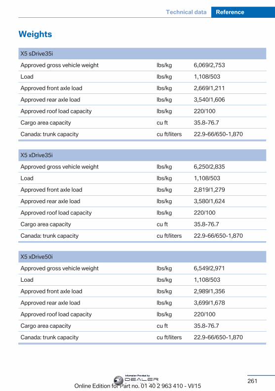
Weights
Seite 261
Technical data Reference
261Online Edition for Part no. 01 40 2 963 410 - VI/15
X5 sDrive35i
Approved gross vehicle weight lbs/kg 6,069/2,753
Load lbs/kg 1,108/503
Approved front axle load lbs/kg 2,669/1,211
Approved rear axle load lbs/kg 3,540/1,606
Approved roof load capacity lbs/kg 220/100
Cargo area capacity cu ft 35.8-76.7
Canada: trunk capacity cu ft/liters 22.9-66/650-1,870
X5 xDrive35i
Approved gross vehicle weight lbs/kg 6,250/2,835
Load lbs/kg 1,108/503
Approved front axle load lbs/kg 2,819/1,279
Approved rear axle load lbs/kg 3,580/1,624
Approved roof load capacity lbs/kg 220/100
Cargo area capacity cu ft 35.8-76.7
Canada: trunk capacity cu ft/liters 22.9-66/650-1,870
X5 xDrive50i
Approved gross vehicle weight lbs/kg 6,549/2,971
Load lbs/kg 1,108/503
Approved front axle load lbs/kg 2,989/1,356
Approved rear axle load lbs/kg 3,699/1,678
Approved roof load capacity lbs/kg 220/100
Cargo area capacity cu ft 35.8-76.7
Canada: trunk capacity cu ft/liters 22.9-66/650-1,870
Information Provided by:
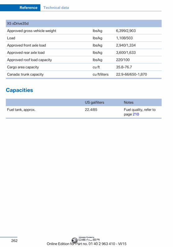
Capacities
US gal/liters Notes
Fuel tank, approx. 22.4/85 Fuel quality, refer topage 210
Seite 262
Reference Technical data
262Online Edition for Part no. 01 40 2 963 410 - VI/15
X5 xDrive35d
Approved gross vehicle weight lbs/kg 6,399/2,903
Load lbs/kg 1,108/503
Approved front axle load lbs/kg 2,940/1,334
Approved rear axle load lbs/kg 3,600/1,633
Approved roof load capacity lbs/kg 220/100
Cargo area capacity cu ft 35.8-76.7
Canada: trunk capacity cu ft/liters 22.9-66/650-1,870
Information Provided by:

AppendixAny updates to the Owner's Manual of the ve‐hicle are listed here.
Seite 263
Appendix Reference
263Online Edition for Part no. 01 40 2 963 410 - VI/15
Information Provided by:
Everything from A to ZIndexAABS, Antilock Brake Sys‐
tem 137 ACC, Active Cruise Control
with Stop & Go 145 Acceleration Assistant, refer
to Launch Control 83 Accessories and parts 7 Activated-charcoal filter 170 Active Blind Spot Detec‐
tion 133 Active Cruise Control with
Stop & Go, ACC 145 Active Protection 135 Active roll stabilization 141 Active seat ventilation,
front 54 Active Steering 141 Adaptive brake assistant 137 Adaptive brake lights, see
Brake force display 135 Adaptive Light Control 106 Additives, oil 234 Adjustments, seats/head re‐
straints 52 After washing vehicle 255 Airbags 109 Airbags, indicator/warning
light 110 Air circulation, refer to Recir‐
culated-air mode 169 Air, dehumidifying, see Cool‐
ing function 168 Air distribution, manual 169 Air flow, automatic climate
control 169 Air outlets, see ventila‐
tion 170 Air pressure, tires 215 Alarm system 45
Alarm, unintentional 47 All around the center con‐
sole 16 All around the roofliner 17 All around the steering
wheel 14 All-season tires, see Winter
tires 224 All-wheel-drive 139 Alternating-code hand-held
transmitter 175 Alternative oil types 234 Ambient light 108 Animal detection, see Night
Vision 127 Antifreeze, washer fluid 80 Antilock Brake System,
ABS 137 Anti-slip control, see
DSC 138 Approved axle load 261 Arrival time 99 Ashtray 176 Ashtray, front 176 Ashtray, rear 177 Assistance when driving
off 137 Assist system, see Intelligent
Safety 118 Attentiveness assistant 135 AUTO H button 74 AUTO H button, refer to Au‐
tomatic Hold 74 AUTO intensity 169 Automatic car wash 254 Automatic climate con‐
trol 167 Automatic Cruise Control
with Stop & Go 145 Automatic Curb Monitor 62
Automatic deactivation,Front-seat passenger air‐bags 111
Automatic headlight con‐trol 105
Automatic Hold 74 Automatic locking 45 Automatic recirculated-air
control 169 Automatic Soft Closing,
doors 40 Automatic tailgate 41 Automatic transmission, see
Steptronic transmission 80 AUTO program, automatic cli‐
mate control 168 AUTO program, intensity 169 Auto Start/Stop function 71 Average fuel consumption 98 Average speed 98 Axle loads, weights 261
BBackrest curvature, see Lum‐
bar support 53 Backrest, seats 52 Backrest, width 54 Bad road trips 195 Band-aids, see First-aid
kit 249 Bar for tow-starting/
towing 251 Battery replacement, vehicle
battery 246 Battery replacement, vehicle
remote control 35 Battery, vehicle 246 Belts, safety belts 57 Beverage holder, cu‐
pholder 186
Seite 264
Reference Everything from A to Z
264Online Edition for Part no. 01 40 2 963 410 - VI/15
Information Provided by:
Biodiesel 211 Blinds, sun protection 48 BMW Advanced Diesel 211 BMW Assist, see user's
manual for Navigation, En‐tertainment and Communi‐cation
BMW Driver’s Guide App 6 BMW Homepage 6 BMW Internet page 6 BMW maintenance sys‐
tem 238 Bonus range, ECO PRO 201 Bottle holder, see Cu‐
pholder 186 Brake assistant 137 Brake assistant, adaptive 137 Brake discs, break-in 192 Brake force display 135 Brake lights, adaptive 135 Brake lights, brake force dis‐
play 135 Brake pads, break-in 192 Braking, hints 193 Breakdown assistance 248 Break-in 192 Brightness of Control Dis‐
play 101 Bulb replacement 241 Bulb replacement, front 242 Bulb replacement, rear 244 Bulbs and lights 241 Button, RES 148 Button, Start/Stop 69 Bypassing, see Jump-start‐
ing 249
CCalifornia Proposition 65
Warning 8 Calling up mirror adjust‐
ment 45 Calling up seat adjust‐
ment 45
Calling up steering wheel ad‐justment 45
Camera lenses, care 257 Camera, rearview cam‐
era 157 Camera, Side View 161 Camera, Top View 160 Can holder, see Cu‐
pholder 186 Car battery 246 Car care products 255 Care, displays 257 Care, vehicle 255 Cargo 196 Cargo area 181 Cargo area, enlarging 181 Cargo area, storage compart‐
ments 187 Cargo cover 181 Cargo, securing 197 Cargo straps, securing
cargo 197 Car key, see Remote con‐
trol 34 Carpet, care 257 Car wash 254 Catalytic converter, see Hot
exhaust system 193 CBS Condition Based Serv‐
ice 238 CD/Multimedia, see user's
manual for Navigation, En‐tertainment and Communi‐cation
Center armrest 185 Center console 16 Central locking system 40 Central screen, see Control
Display 18 Changes, technical, see Own
Safety 7 Changing parts 240 Changing wheels 244 Changing wheels/tires 223 Chassis number, see vehicle
identification number 10
Check Control 89 Checking the engine oil level
electronically 232 Checking the oil level elec‐
tronically 232 Children, seating position 64 Children, transporting
safely 64 Child restraint fixing sys‐
tem 64 Child restraint fixing system
LATCH 66 Child restraint fixing systems,
mounting 65 Child safety locks 68 Child seat, mounting 65 Child seats 64 Chrome parts, care 256 Cigarette lighter 177 Cleaning displays 257 Climate control 167 Climate control wind‐
shield 193 Clock 94 Closing/opening via door
lock 39 Closing/opening with remote
control 37 Clothes hooks 187 Coasting 203 Coasting with engine decou‐
pled, coasting 203 Coasting with idling en‐
gine 203 Cockpit 14 Cold starting, refer to Starting
the engine 70 Combination switch, refer to
Wiper system 77 Combination switch, see Turn
signals 76 Comfort Access 43 COMFORT program, Driving
Dynamics Control 143 Compact wheel, see Emer‐
gency wheel 244
Seite 265
Everything from A to Z Reference
265Online Edition for Part no. 01 40 2 963 410 - VI/15
Information Provided by:
Compartments in thedoors 184
Compass 99 Compressor 225 Condensation on win‐
dows 170 Condensation under the vehi‐
cle 195 Condition Based Service
CBS 238 Confirmation signal 45 ConnectedDrive, see user's
manual for Navigation, En‐tertainment and Communi‐cation
ConnectedDrive Services Connecting electrical devi‐
ces 178 Continued driving with a flat
tire 114, 117 Control Display 18 Control Display, settings 100 Controller 19 Control systems, driving sta‐
bility 137 Convenient opening with the
remote control 38 Coolant 236 Coolant level 236 Coolant temperature 93 Cooler 179 Cooling function 168 Cooling, maximum 168 Cooling system 236 Cornering light 106 Corrosion on brake discs 194 Cosmetic mirror 176 Courtesy lamps during un‐
locking 37 Courtesy lamps with the vehi‐
cle locked 38 Cruise control 151 Cruise control, active with
Stop & Go 145 Cruise Control, refer to Active
Cruise Control 145
Cruising range 94 Cupholder 186 Current fuel consumption 94
DDamage, tires 223 Data, technical 260 Date 94 Daytime running lights 106 Defrosting, see Windows, de‐
frosting 170 Dehumidifying, air 168 Deleting personal data 24 Deletion of personal data 24 Departure time, parked-car
ventilation 173 Destination distance 99 Diesel exhaust fluid, at low
temperatures 212 Diesel exhaust fluid, having
refilled 212 Diesel exhaust fluid, on mini‐
mum 212 Diesel exhaust fluid, replen‐
ishing yourself 212 Diesel fuel 211 Diesel particulate filter 193 Digital clock 94 Dimensions 260 Dimmable exterior mirrors 62 Dimmable interior rearview
mirror 63 Direction indicator, see Turn
signals 76 Display, electronic, instru‐
ment cluster 85 Display in windshield 101 Display lighting, see Instru‐
ment lighting 108 Displays 86 Displays, cleaning 257 Disposal, coolant 237 Disposal, vehicle battery 247 Distance control, see
PDC 154
Distance to destination 99 Divided screen view, split
screen 23 Door lock 39 Door lock, see Remote con‐
trol 34 Doors, Automatic Soft Clos‐
ing 40 Downhill control 140 DPC, see Dynamic Perform‐
ance Control 137 Drink holder, third row of
seats 187 Drive mode 142 Drive-off assistant 137 Drive-off assistant, see
DSC 138 Driving Dynamics Con‐
trol 142 Driving instructions, break-
in 192 Driving notes, general 192 Driving on bad roads 195 Driving stability control sys‐
tems 137 Driving tips 192 DSC Dynamic Stability Con‐
trol 138 DTC Dynamic Traction Con‐
trol 139 Dynamic Performance Con‐
trol DPC 137 Dynamic Stability Control
DSC 138 Dynamic Traction Control
DTC 139
EECO PRO 200 ECO PRO, bonus range 201 ECO PRO display 200 ECO PRO displays 87 ECO PRO driving mode 200 ECO PRO mode 200
Seite 266
Reference Everything from A to Z
266Online Edition for Part no. 01 40 2 963 410 - VI/15
Information Provided by:
ECO PRO Tip - driving in‐struction 202
EfficientDynamics 202 Electronic displays, instru‐
ment cluster 85 Electronic oil measure‐
ment 232 Electronic Stability Program
ESP, see DSC 138 Emergency detection, remote
control 35 Emergency release, fuel filler
flap 209 Emergency release, parking
brake 75 Emergency Request 248 Emergency start function, en‐
gine start 35 Emergency unlocking, trans‐
mission lock 83 Emergency wheel 244 Energy Control 94 Energy recovery 95 Engine, automatic Start/Stop
function 71 Engine, automatic switch-
off 71 Engine compartment 229 Engine compartment, work‐
ing in 230 Engine coolant 236 Engine idling when driving,
coasting 203 Engine oil 232 Engine oil, adding 233 Engine oil additives 234 Engine oil change 234 Engine oil filler neck 233 Engine oil temperature 93 Engine oil types, alterna‐
tive 234 Engine oil types, suitable 234 Engine start during malfunc‐
tion 35 Engine start, jump-start‐
ing 249
Engine start, refer to Startingthe engine 70
Engine stop 70 Engine temperature 93 Entering a car wash 254 Equipment, interior 174 Error displays, see Check
Control 89 ESP Electronic Stability Pro‐
gram, see DSC 138 Exchanging wheels/tires 223 Exhaust system 193 Exterior mirror, automatic
dimming feature 62 Exterior mirrors 61 External start 249 External temperature dis‐
play 93 External temperature warn‐
ing 93 Eyes for securing cargo 197
FFailure message, see Check
Control 89 False alarm, see Unintentional
alarm 47 Fan, see Air flow 169 Filler neck for engine oil 233 Fine wood, care 256 First-aid kit 249 Fitting for towing, see Tow fit‐
ting 252 Flat tire, changing
wheels 244 Flat Tire Monitor FTM 116 Flat tire, Tire Pressure Moni‐
tor TPM 112 Flat tire, warning
lamp 113, 117 Flooding 193 Floor carpet, care 257 Floor mats, care 257 Folding back rear seat back‐
rests 181
Fold-out position, wiper 79 Foot brake 193 Front airbags 109 Front center armrest 185 Front cupholder 186 Front-end collision warning
with braking function 122 Front-end collision warning
with City Braking func‐tion 119
Front fog lamps, , LED, bulbreplacement 244
Front fog lights 107 Front fog lights/cornering
lights, bulb replace‐ment 243
Front lights 242 Front-seat passenger airbags,
automatic deactivation 111 Front-seat passenger airbags,
indicator lamp 111 Front seats 52 FTM Flat Tire Monitor 116 Fuel 210 Fuel consumption, see Aver‐
age fuel consumption 98 Fuel filler flap 208 Fuel gauge 93 Fuel lid 208 Fuel quality 210 Fuel recommendation 210 Fuel, tank capacity 262 Fuse 247
GGarage door opener, see Uni‐
versal Integrated RemoteControl 174
Gasoline 210 Gear change, Steptronic
transmission 81 Gear shift indicator 96 General driving notes 192 Glare shield 176 Glasses compartment 186
Seite 267
Everything from A to Z Reference
267Online Edition for Part no. 01 40 2 963 410 - VI/15
Information Provided by:
Glass sunroof, refer to Panor‐amic glass sunroof 49
Glove compartment 183 Gross vehicle weight, ap‐
proved 261
HHandbrake, see Parking
brake 73 Hand-held transmitter, alter‐
nating code 175 Hazard warning flashers 248 HDC Hill Descent Con‐
trol 140 Head airbags 109 Headlight control, auto‐
matic 105 Headlight courtesy delay fea‐
ture 105 Headlight flasher 77 Headlight glass 242 Headlights 242 Headlights, care 255 Head restraints 52 Head restraints, front 58 Head restraints, rear 59 Head-up Display 101 Head-up Display, care 257 Heavy cargo, stowing 197 High-beam Assistant 106 High beams 77 High beams/low beams, see
High-beam Assistant 106 Hill Descent Control
HDC 140 Hills 194 Hill start assistant, see Drive-
off assistant 137 Holder for beverages 186 Homepage 6 Hood 230 Horn 14 Hot exhaust system 193 HUD Head-up Display 101 Hydroplaning 193
IIce warning, see External
temperature warning 93 Icy roads, see External tem‐
perature warning 93 Identification marks, tires 221 Identification number, see ve‐
hicle identification num‐ber 10
iDrive 18 Ignition key, see Remote con‐
trol 34 Ignition off 69 Ignition on 69 Indication of a flat
tire 113, 117 Indicator and alarm lamps,
see Check Control 89 Indicator lamp, see Check
Control 89 Individual air distribution 169 Individual settings, see Per‐
sonal Profile 35 Inflation pressure, tires 215 Inflation pressure warning
FTM, tires 116 Info display, refer to On-
Board computer 98 Information 6 Initialize, Tire Pressure Moni‐
tor TPM 113 Initializing, Flat Tire Monitor
FTM 116 Instrument cluster 85 Instrument cluster, electronic
displays 85 Instrument display, multifunc‐
tional 86 Instrument lighting 108 Integrated key 34 Integrated Owner's Manual in
the vehicle 29 Intelligent Emergency Re‐
quest 248 Intelligent Safety 118
Intensity, AUTO pro‐gram 169
Interior equipment 174 Interior lights 108 Interior lights during unlock‐
ing 37 Interior lights with the vehicle
locked 38 Interior motion sensor 46 Interior rearview mirror, auto‐
matic dimming feature 63 Internet page 6 Interval display, service re‐
quirements 95 Interval mode 78
JJacking points for the vehicle
jack 244 Joystick, Steptronic transmis‐
sion 81 Jump-starting 249
KKey/remote control 34 Keyless Go, see Comfort Ac‐
cess 43 Key Memory, see Personal
Profile 35 Kickdown, Steptronic trans‐
mission 81 Knee airbag 110
LLabel on recommended
tires 224 Lamp in the exterior mirror,
see Active Blind Spot De‐tection 133
Lamp replacement 241 Lamp replacement, front 242 Lamp replacement, rear 244 Lane departure warning 131
Seite 268
Reference Everything from A to Z
268Online Edition for Part no. 01 40 2 963 410 - VI/15
Information Provided by:
Lane margin, warning 131 Language on Control Dis‐
play 101 Lashing eyes, securing
cargo 197 LATCH child restraint sys‐
tem 66 Launch Control 83 Leather, care 255 LED headlights, bulb replace‐
ment 243 LEDs, light-emitting di‐
odes 242 Letters and numbers, enter‐
ing 25 Light 104 Light alloy wheels, care 256 Light control 106 Light-emitting diodes,
LEDs 242 Lighting 104 Lights and bulbs 241 Light switch 104 Load 197 Loading 196 Lock, door 39 Locking/unlocking via door
lock 39 Locking/unlocking with re‐
mote control 37 Locking, automatic 45 Locking, settings 44 Lock, power window 48 Locks, doors, and win‐
dows 68 Low beams 104 Low beams, automatic, see
High-beam Assistant 106 Lower back support 53 Lower tailgate 43 Low-Sulfur Diesel 211 Luggage rack, see Roof-
mounted luggage rack 198 Lumbar support 53
MMaintenance 238 Maintenance require‐
ments 238 Maintenance, service require‐
ments 95 Maintenance system,
BMW 238 Make-up mirror 176 Malfunction displays, see
Check Control 89 Malfunction, self-leveling sus‐
pension 142 Manual air distribution 169 Manual air flow 169 Manual brake, see Parking
brake 73 Manual mode, Steptronic
transmission 82 Manual operation, door
lock 39 Manual operation, exterior
mirrors 62 Manual operation, fuel filler
flap 209 Manual operation, Park Dis‐
tance Control PDC 155 Manual operation, parking
brake 75 Manual operation, rearview
camera 157 Manual operation, Top
View 160 Marking, run-flat tires 225 Master key, see Remote con‐
trol 34 Maximum cooling 168 Maximum speed, display 96 Maximum speed, winter
tires 224 Measurement, units of 101 Medical kit 249 Memory for seat, mirrors,
steering wheel 60 Menu, EfficientDynamics 202
Menu in instrument clus‐ter 97
Menus, operating, iDrive 18 Menus, refer to iDrive operat‐
ing concept 20 Messages, see Check Con‐
trol 89 Microfilter 170 Minimum tread, tires 223 Mirror 61 Mirror memory 60 Mobile communication devi‐
ces in the vehicle 193 Mobility System 225 Modifications, technical, see
Own Safety 7 Moisture in headlight 242 Monitor, see Control Dis‐
play 18 Mounting of child restraint
systems 65 Moving sun visor 176 Multifunctional instrument
display 86 Multifunction steering wheel,
buttons 14
NNavigation, see user's manual
for Navigation, Entertain‐ment and Communication
Neck restraints, front, seeHead restraints 58
Neck restraints, rear, seeHead restraints 59
Neutral cleaner, see wheelcleaner 256
New wheels and tires 223 Night Vision 127 Night Vision device, see Night
Vision 127 Nylon rope for tow-starting/
towing 251
Seite 269
Everything from A to Z Reference
269Online Edition for Part no. 01 40 2 963 410 - VI/15
Information Provided by:
OOBD Onboard Diagnosis 239 OBD, see OBD Onboard Di‐
agnosis 239 Object detection, see Night
Vision 127 Obstacle marking, rearview
camera 158 Octane rating, see Recom‐
mended fuel grade 210 Odometer 93 Office, see user's manual for
Navigation, Entertainmentand Communication
Offroad trips 195 Oil 232 Oil, adding 233 Oil additives 234 Oil change 234 Oil change interval, service
requirements 95 Oil filler neck 233 Oil types, alternative 234 Oil types, suitable 234 Old batteries, disposal 247 On-board computer 98 On-board computer, refer to
On-board computer 98 Onboard monitor, see Control
Display 18 Onboard vehicle tool kit 240 Opening/closing via door
lock 39 Opening and closing 34 Opening and closing, without
remote control 39 Opening and closing, with re‐
mote control 37 Operating concept, iDrive 18 Optional equipment, standard
equipment 7 Outside air, refer to Auto‐
matic recirculated-air con‐trol 169
Overheating of engine, seeCoolant temperature 93
Own Safety 7
PPaint, vehicle 255 Panoramic glass sunroof 49 Parallel parking assistant 163 Park Distance Control
PDC 154 Parked-car ventilation 173 Parked vehicle, condensa‐
tion 195 Parking aid, see PDC 154 Parking assistant 163 Parking brake 73 Parking lights 104 Parking with Automatic
Hold 74 Particulate filter 193 Parts and accessories 7 Passenger side mirror, tilting
downward 62 Pathway lines, rearview cam‐
era 158 PDC Park Distance Con‐
trol 154 Pedestrian detection, see
Night Vision 127 Pedestrian warning with city
braking function 125 Personal Profile 35 Personal Profile, exporting
profiles 36 Pinch protection system,
glass sunroof 50 Pinch protection system, win‐
dows 48 Plastic, care 256 Power failure 247 Power windows 47 Prescribed engine oil
types 234 Pressure, tire air pres‐
sure 215
Pressure warning FTM,tires 116
Profile, see Personal Pro‐file 35
Programmable memory but‐tons, iDrive 24
Protective function, glasssunroof 50
Protective function, win‐dows 48
Push-and-turn switch, seeController 19
RRadiator fluid 236 Radio-operated key, see Re‐
mote control 34 Radio ready state 69 Radio, see user's manual for
Navigation, Entertainmentand Communication
Rain sensor 78 Rapeseed-oil methyl ester
RME 211 Rear automatic climate con‐
trol 171 Rear center armrest 185 Rear cooler 179 Rear drink holder 186 Rear lights 244 Rear seats 55 Rear ventilation, third row of
seats, ventilation, third rowof seats 171
Rearview camera 156 Rearview mirror 61 Rear window defroster 170 Recirculated-air mode 169 Recommended fuel
grade 210 Recommended tire
brands 224 Refueling 208 Remaining range 94 Remote control/key 34
Seite 270
Reference Everything from A to Z
270Online Edition for Part no. 01 40 2 963 410 - VI/15
Information Provided by:
Remote control, malfunc‐tion 39
Remote control, univer‐sal 174
Replacement fuse 247 Replacing parts 240 Replacing wheels/tires 223 Reporting safety malfunc‐
tions 10 RES button 148 RES button, see Active
Cruise Control, ACC 145 RES button, see Cruise con‐
trol 151 Reserve warning, see
Range 94 Reset, Tire Pressure Monitor
TPM 113 Residual heat, automatic cli‐
mate control 169 Retaining straps, securing
cargo 197 Retreaded tires 224 RME rapeseed-oil methyl es‐
ter 211 Roadside parking lights 105 Roller sunblinds 48 RON recommended fuel
grade 210 Roofliner 17 Roof load capacity 261 Roof-mounted luggage
rack 198 Rope for tow-starting/
towing 251 RSC Run Flat System Com‐
ponent, see Run-flattires 225
Rubber components,care 256
Run-flat tires 225
SSafe braking 193
Safety belt reminder for driv‐er's seat and front passen‐ger seat 58
Safety belts 57 Safety belts, care 257 Safety Package, see Active
Protection 135 Safety switch, windows 48 Safety systems, airbags 109 Saving fuel 199 Screen, see Control Dis‐
play 18 Screwdriver, see Onboard ve‐
hicle tool kit 240 Screw thread, refer to Screw
thread for tow fitting, screwthread for tow fitting 253
Sealant 225 Seat belts, see Safety
belts 57 Seat heating, front 54 Seat heating, rear 56 Seating position for chil‐
dren 64 Seat, mirror, and steering
wheel memory 60 Seats 52 Seats, front 52 Seats, rear 55 Seat ventilation, front 54 Selection list in instrument
cluster 97 Selector lever, Steptronic
transmission 81 Self-leveling suspension, air
suspension 141 Self-leveling suspension,
malfunction 142 Sensors, care 257 Service and warranty 8 Service requirements, Condi‐
tion Based ServiceCBS 238
Service requirements, dis‐play 95
Services, ConnectedDrive
SET button, see ActiveCruise Control, ACC 145
SET button, see Cruise con‐trol 151
Settings, locking/unlock‐ing 44
Settings on Control Dis‐play 100
Settings, storing for seat, mir‐rors, steering wheel 60
Shift paddles on the steeringwheel 83
Shift point indicator 88 Shoulder support 54 Side airbags 109 Side View 161 Signaling, horn 14 Signals when unlocking 45 Sitting safely 52 Size 260 Ski and snowboard bag 182 Slide/tilt glass roof 49 Smoker's package 176 Snow chains 228 Socket, OBD Onboard Diag‐
nostics 239 Sockets, see Connecting
electrical devices 178 Soot particulate filter 193 SOS button 248 Spare fuse 247 Spare tire, see Emergency
wheel 244 Speed, average 98 Speed limit detection, on-
board computer 99 Speed limiter, display 96 Speed Limit Information 96 Speed warning 100 Split screen 23 SPORT+ - program, Dynamic
Driving Control 143 Sport displays, torque dis‐
play, performance dis‐play 99
Seite 271
Everything from A to Z Reference
271Online Edition for Part no. 01 40 2 963 410 - VI/15
Information Provided by:

SPORT program, driving dy‐namics 143
Sport program, transmis‐sion 82
Stability control systems 137 Start/stop, automatic func‐
tion 71 Start/Stop button 69 Start function during malfunc‐
tion 35 Starting the engine 70 Status control display,
tires 113 Status information, iDrive 23 Status of Owner's Manual 7 Steering, Active Steering 141 Steering wheel, adjusting 63 Steering wheel heating 63 Steering wheel memory 60 Steptronic Sport transmis‐
sion, see Steptronic trans‐mission 80
Steptronic transmission 80 Stopping the engine 70 Storage compartment on the
center console 184 Storage compartments 183 Storage compartments, loca‐
tions 183 Storage compartment third
row of seats 184 Storage, tires 224 Storing the vehicle 257 Suitable engine oil types 234 Summer tires, tread 222 Sun visor 176 Supplementary text mes‐
sage 92 Surround View 156 Suspension settings 142 Switch for Dynamic Driving
Control 142 Switch, refer to Cockpit 14 Symbols 6 Symbols in the status field 23
SYNC program, automatic cli‐mate control 169
TTachometer 93 Tailgate, automatic 41 Tailgate via remote con‐
trol 38 Tail lights 244 Technical changes, see Own
Safety 7 Technical data 260 Telephone, see user's manual
for Navigation, Entertain‐ment and Communication
Temperature, automatic cli‐mate control 168
Temperature display for ex‐ternal temperature 93
Temperature, engine oil 93 Terminal, starting aid 250 Text message, supplemen‐
tary 92 Theft alarm system, see
Alarm system 45 Thermal camera, see Night
Vision 127 Thigh support 53 Third row of seats 56 Tilt alarm sensor 46 Time of arrival 99 Tire damage 223 Tire identification marks 221 Tire inflation pressure 215 Tire inflation pressure moni‐
tor, see FTM 116 Tire Pressure Monitor
TPM 112 Tires, changing 223 Tire sealant 225 Tires, everything on wheels
and tires 215 Tires, run-flat tires 225 Tire tread 222
Tone, see user's manual forNavigation, Entertainmentand Communication
Tool 240 Top View 159 Total vehicle weight 261 Touchpad 21 Tow fitting 252 Towing 251 Tow lug, see Tow fitting 252 Tow-starting 251 TPM Tire Pressure Moni‐
tor 112 Traction control 139 TRACTION, driving dynam‐
ics 139 TRACTION program, Dy‐
namic Driving Control 143 Transmission lock, electronic
unlocking 83 Transmission, see Steptronic
transmission 80 Transporting children
safely 64 Tread, tires 222 Triple turn signal activa‐
tion 77 Trip odometer 93 Trip on-board computer 99 Trip recorder, see Trip odom‐
eter 93 Turning circle lines, rearview
camera 158 Turn signals, operation 76
UUnintentional alarm 47 Units of measurement 101 Universal remote control 174 Unlock button, Steptronic
transmission 81 Unlocking/locking via door
lock 39 Unlocking/locking with re‐
mote control 37
Seite 272
Reference Everything from A to Z
272Online Edition for Part no. 01 40 2 963 410 - VI/15
Information Provided by:
Unlocking, settings 44 Unpaved roads, cross-coun‐
try trips 195 Updates made after the edito‐
rial deadline 7 Upholstery care 256 USB interface 179
VVanity mirror 176 Variable steering 141 Vehicle battery 246 Vehicle battery, replac‐
ing 246 Vehicle, break-in 192 Vehicle care 255 Vehicle features and op‐
tions 7 Vehicle identification num‐
ber 10 Vehicle jack 244 Vehicle paint 255 Vehicle storage 257 Vehicle wash 254 Ventilation 170 Ventilation, see Parked-car
ventilation 173 Venting, see ventilation 170 Vent, see ventilation 170 Vertical Dynamic Control 141 VIN, see vehicle identification
number 10 Voice activation system 26
WWarning and indicator lamps,
see Check Control 89 Warning displays, see Check
Control 89 Warning lamp in the exterior
mirror, see Active Blind SpotDetection 133
Warning messages, seeCheck Control 89
Warning triangle 249 Warranty 7 Washer fluid 80 Washer nozzles, wind‐
shield 79 Washer system 77 Washing, vehicle 254 Water on roads 193 Weights 261 Welcome lamps during un‐
locking 37 Welcome lights 105 Wheel cleaner 256 Wheels, changing 223 Wheels, everything on wheels
and tires 215 Wheels, Flat Tire Monitor
FTM 116 Wheels, Tire Pressure Moni‐
tor TPM 112 Window defroster, rear 170 Windows, powered 47 Windshield, climate con‐
trol 193 Windshield washer fluid 80 Windshield washer noz‐
zles 79 Windshield washer sys‐
tem 77 Windshield washer system,
see washer/wiper sys‐tem 77
Windshield wiper 77 Winter storage, care 257 Winter tires, suitable
tires 224 Winter tires, tread 222 Wiper 77 Wiper blades, replacing 240 Wiper fluid 80 Wiper, fold-out position 79 Wiper system 77 Wood, care 256 Word match concept, naviga‐
tion 25
Wrench, see Onboard vehicletool kit 240
XxDrive 139 Xenon headlights, bulb re‐
placement 242
Seite 273
Everything from A to Z Reference
273Online Edition for Part no. 01 40 2 963 410 - VI/15
Information Provided by:

Information Provided by:
More about BMW
bmwusa.comThe Ultimate
Driving Machine®
01 4
0 2
963
410
ue
*BL296341000V*
Online Edition for Part no. 01 40 2 963 410 - VI/15
Information Provided by:
Top Related