


Languages
Pages
Legal

Balance Technology Inc bull 7035 Jomar Drive Whitmore Lake MI 48189 bull 734-769-2100 bull USA wwwbalancetechnologycom
P R E C I S I O N M E A S U R E M E N T A N D T E S T I N G E Q U I P M E N T A N D S E R V I C E S
The Basics of Balancing 202
Gary K Grim
John W Haidler
Bruce J Mitchell
Copyright copy 2014 Balance Technology Inc
Do not Distribute or Duplicate without the Authorized
Written Consent of BTI (Balance Technology Inc)
Balance Technology Inc bull 7035 Jomar Drive Whitmore Lake MI 48189 bull 734-769-2100 bull USA wwwbalancetechnologycom
P R E C I S I O N M E A S U R E M E N T A N D T E S T I N G E Q U I P M E N T A N D S E R V I C E S
About Us
Headquartered near Ann Arbor Michigan (USA)
Balance Technology Inc BTI is a thriving
Precision Measurement and Testing company
with a strong domestic and international presence
Since 1968 BTI has set the standard in industrial
Precision Measurement amp Testing systems With
13000 plus systems shipped worldwide our team
approach to customer satisfaction and technical
innovations has forged our reputation as an
industry leader and trusted partner
BTI engineers and manufactures a complete line of industrial precision measurement and testing
equipment including static and dynamic balancing equipment dimensional gages mass centering
equipment eddy current crack detection systems surface finish measurement equipment NVH
equipment (noise vibration and harshness) functional test stands spinners motor testers and
resonant frequency measurement systems We also engineer and manufacture specialized test
systems including torque-to-turn backlash end play and destructive test equipment
Additionally BTIrsquos unique ability to combine the aforementioned technologies into one fully
integrated system enables our clients to reduce capital expenditures increase product quality and
minimize floor space requirements
Let our staff of over 50 engineers design a custom solution for your specific requirements
Furthermore our commercial Measurement amp Testing Services Group (M amp T Services) can assist
with everything from prototype testing RampD work master certification to running small to medium
production runs
Our service department is available 24 hours a day 365 days a year We
also offer remote diagnostics for ldquoreal timerdquo software updates
BTI World Headquarters
All our equipment is engineered amp manufactured in the USA
Page 3 of 28
Balance Technology Inc bull 7035 Jomar Drive Whitmore Lake MI 48189 bull 734-769-2100 bull USA wwwbalancetechnologycom
P R E C I S I O N M E A S U R E M E N T A N D T E S T I N G E Q U I P M E N T A N D S E R V I C E S
Page 4 of 28
Balance Technology Inc bull 7035 Jomar Drive Whitmore Lake MI 48189 bull 734-769-2100 bull USA wwwbalancetechnologycom
P R E C I S I O N M E A S U R E M E N T A N D T E S T I N G E Q U I P M E N T A N D S E R V I C E S
What we dohellip
We engineer custom equipment for all your Precision Measurement amp Testing Needs
Page 5 of 28
Balance Technology Inc bull 7035 Jomar Drive Whitmore Lake MI 48189 bull 734-769-2100 bull USA wwwbalancetechnologycom
P R E C I S I O N M E A S U R E M E N T A N D T E S T I N G E Q U I P M E N T A N D S E R V I C E S
THE BASICS OF BALANCING 202
Gary K Grim
John W Haidler
Bruce J Mitchell Jr
Why Balance Rotating components experience significant quality and performance improvements
when balanced Balancing is the process of aligning a principal inertia axis with the geometric axis of
rotation through the addition or removal of material By doing so the centrifugal forces are reduced
minimizing vibration noise and associated wear
Virtually all rotating components experience significant improvements when balanced Consumers
throughout the global market continue to demand value in the products they purchase They demand
performance - smaller lighter more efficient more powerful quieter smoother running and longer
lasting Balancing can contribute to each of these and is one of the most cost effective means of
providing value to the consumer
FUNDAMENTAL TERMS
For a better understanding of balancing it is necessary to have an understanding of its terminology
and its fundamental concepts For additional terminology see ISO 1925 Mechanical Vibration ndash
Balancing - Vocabulary
MASS CENTER
The center of mass is the point about which the total mass of a rigid body is equally distributed It is
useful to assume that all the mass is concentrated at this one point for simple dynamic analyses A
force vector that acts through this point will move the body in a straight line with no rotation
according to Newtonrsquos second law of motion F = mmiddota The sum of all forces acting on a body F
cause a body to accelerate at a rate a proportional to its mass m
Page 6 of 28
Balance Technology Inc bull 7035 Jomar Drive Whitmore Lake MI 48189 bull 734-769-2100 bull USA wwwbalancetechnologycom
P R E C I S I O N M E A S U R E M E N T A N D T E S T I N G E Q U I P M E N T A N D S E R V I C E S
CENTER OF GRAVITY
For normal commercial balancing applications the mass center and the center of gravity occur at the
same point This does not hold true for applications involving a non-uniform gravitational field
however the scale of most balancing applications is very small with respect to gradients in the
earthrsquos gravitational field and the terms are synonymous
AXIS OF ROTATION
The axis of rotation is the true centerline of rotation ndash the instantaneous line about which a part
rotates It is also referred to as the shaft axis or the geometric axis The axis of rotation is generally
determined by geometric features on the rotor or by its support bearings The quality of the mounting
datums greatly influence the ability to balance a part Non-circular surfaces non-flat surfaces
irregular or loose bearings all allow or cause variations in the position of the rotation axis Any
variation of the axis appears to be motion of the mass center with respect to the axis and contributes
to non-repeatability
PRINCIPAL INERTIA AXIS
The mass moment of inertia is the rotational counterpart of mass and is a measure of mass
distribution about an axis For a particle it is the product of mass times the square of the distance
from the axis to the particle I = mmiddotrsup2 For a rigid body it is an integral I = int rsup2middotdm Since the mass
moment of inertia is calculated with respect to an arbitrarily specified axis it can have just about any
value depending on the axis chosen It turns out that all rigid bodies have at least one set of axes
about which the body is perfectly balanced These axes are known as the principal axes They are
mutually orthogonal and have their origin at the mass center There are corresponding principal
moments of inertia for each
In balancing it is useful to describe the central principal axis as the principal axis that is most closely
in line with the axis of rotation It is also known as the balance axis or the mass axis A rotor with an
axis of rotation that is not coincident with the central principal axis has unbalance The magnitude of
unbalance will be a function of the angle between the axes and the distance of the origin (mass
center) from the axis of rotation
Page 7 of 28
Balance Technology Inc bull 7035 Jomar Drive Whitmore Lake MI 48189 bull 734-769-2100 bull USA wwwbalancetechnologycom
P R E C I S I O N M E A S U R E M E N T A N D T E S T I N G E Q U I P M E N T A N D S E R V I C E S
CENTRIFUGAL FORCE
A particle made to travel along a circular path generates a centrifugal force directed outward along
the radial line between the center of rotation and the particle As the particle rotates about the center
point so does the centrifugal force
Centrifugal force is an inertia force and is actually the bodyrsquos reaction to an externally applied force
For circular motion the external force is known as centripetal force The centripetal force acts on the
particle in a radially inward direction They both have the same magnitude but differ in the direction of
action
Similarly a rotor with mass center slightly displaced form the axis of rotation will generate centrifugal
force This is the force associated with static unbalance The shaft supports counteract the forces of
unbalance ndash the externally applied centripetal force
It should be noted here that the quantity mr is known as unbalance and that centrifugal force is the
product of unbalance and angular velocity squared While unbalance force (Fcentrifugal) increases
rapidly with speed the unbalance quantity itself (mr) does not change at all
r
m
Fcentrifugal = mmiddotrmiddotω2
ω
Fcentrifugal Fcentrifugal
Fcentripetal
Page 8 of 28
Balance Technology Inc bull 7035 Jomar Drive Whitmore Lake MI 48189 bull 734-769-2100 bull USA wwwbalancetechnologycom
P R E C I S I O N M E A S U R E M E N T A N D T E S T I N G E Q U I P M E N T A N D S E R V I C E S
With rigid bodies the unbalance remains the same although an increase in speed causes an increase
in force The increased force will in turn cause increased motion depending on the stiffness of the
shaft or the shaft supports Force increases exponentially as the square of the change in speed
Twice the speed equates to four times the force and four times the motion
F = mmiddotrmiddotω2 = Umiddotω2
Unbalance force for various unbalances are depicted in the following chart
It should be noted that system flexibility limits the growth of centrifugal force This is discussed in
greater detail in a later section MOTION OF UNBALANCED PARTS
U = 1 in oz
U = 1 in oz
U = 1000 g mm
U = 100 g mm
Page 9 of 28
Balance Technology Inc bull 7035 Jomar Drive Whitmore Lake MI 48189 bull 734-769-2100 bull USA wwwbalancetechnologycom
P R E C I S I O N M E A S U R E M E N T A N D T E S T I N G E Q U I P M E N T A N D S E R V I C E S
MOMENT AND COUPLE
A couple is a system of two parallel forces equal in magnitude and acting in opposite directions A
couple causes a moment or torque proportional to the distance between the parallel forces Its effect
is to cause a twisting or turning motion
The net moment is determined by summing the moment of all forces about any point on the body
ΣM = Fd
In this case the moment or couple acts in a clockwise direction The moment of a couple is
expressed in units of forcedistance Frequently used units include inchmiddotpounds (inlbs) footmiddotpounds
(ftlbs) and Newtonmiddotmeters (Nm)
This unrestrained body will rotate in a clockwise direction about its mass center
Page 10 of 28
Balance Technology Inc bull 7035 Jomar Drive Whitmore Lake MI 48189 bull 734-769-2100 bull USA wwwbalancetechnologycom
P R E C I S I O N M E A S U R E M E N T A N D T E S T I N G E Q U I P M E N T A N D S E R V I C E S
This body is restrained at one point and will rotate in a clockwise direction about that point
A body restrained at two points will not rotate at all The reaction forces at the points of constraint will
be equal and proportional to the distance between the constraints The reaction forces form a
counteracting couple
For the restrained rotor sumM = 0 = Fmiddotd - Rmiddots and R = Fmiddot(ds) The restraining forces R would
correspond to bearing reactions for an applied couple of Fmiddotd It is interesting to note that for s=d the
reaction forces will have the same magnitude as the couple forces For sgtd the reaction forces will
be smaller For sltd the reaction forces will be larger potentially much larger if sltltd This case is a
good illustration of the forces associated with couple unbalance
Page 11 of 28
Balance Technology Inc bull 7035 Jomar Drive Whitmore Lake MI 48189 bull 734-769-2100 bull USA wwwbalancetechnologycom
P R E C I S I O N M E A S U R E M E N T A N D T E S T I N G E Q U I P M E N T A N D S E R V I C E S
WEIGHT AND MASS
The units of weight and mass are often used interchangeably and somewhat loosely in balancing
This is generally acceptable provided the balance computer displays units that are consistent or
easily converted to those of the weights in use or the scale used to make the weights The distinction
between weight and mass becomes an issue when calculating unbalance force It should be
understood that weight and force have the same units Newtons (N) in the metric system and pounds
(lbs) in the English system Mass has the units of grams (g) or kilograms (kg) in the metric system
and slugs in the English system
Slugs are generally avoided in favor of expression in fundamental units
1 slug = 1 lbmiddotsec2ft = 0833 lbmiddotsec2in
In the metric system
F = mmiddotrmiddotω2
F force in Newtons
m mass in kilograms
r radius in meters
ω angular velocity in radianssec
In the English system
F = (wg)middotrmiddotω2
F force in pounds
w weight in pounds
g acceleration of gravity is 386 insec2
r radius in inches
ω angular velocity in radianssec
To convert revolutions per minute (rpm) into radianssec multiply by 1047 (2π60)
Page 12 of 28
Balance Technology Inc bull 7035 Jomar Drive Whitmore Lake MI 48189 bull 734-769-2100 bull USA wwwbalancetechnologycom
P R E C I S I O N M E A S U R E M E N T A N D T E S T I N G E Q U I P M E N T A N D S E R V I C E S
TYPES OF UNBALANCE
The location of the mass center and the principal inertia axes are determined by the distribution of
mass within the part Unbalance exists when the axis of rotation is not coincident with a principal
inertia axis
It is important to draw a distinction between unbalance and balance correction Unbalance is a mass
property It becomes a characteristic of the part when an axis of rotation is defined Balance
correction is a means to alter the mass properties to improve the alignment of the axis of rotation with
the mass center andor the central principal axis Both can be expressed as weights and radii and
have shared terminology This section discusses unbalance as a mass property
STATIC UNBALANCE
A condition of static unbalance exists when the mass center does not lie on the axis of rotation Static
unbalance is also known as Force Unbalance As defined static unbalance is an ideal condition it
has the additional condition that the axis of rotation be parallel to the central principal axis ndash no
couple unbalance
Page 13 of 28
Balance Technology Inc bull 7035 Jomar Drive Whitmore Lake MI 48189 bull 734-769-2100 bull USA wwwbalancetechnologycom
P R E C I S I O N M E A S U R E M E N T A N D T E S T I N G E Q U I P M E N T A N D S E R V I C E S
Static unbalance has the units of weightmiddotlength or masslength and is expressed
U = wmiddotr or U = mmiddotr
where w is weight (or m is mass) and r is the effective radius of the weight Common units of static
unbalance are inmiddotoz or gmiddotmm
Another convenient expression of static unbalance is the total weight of the workpiece w times the
distance between the mass center and the axis of rotation e
U = wmiddote
As discussed earlier a workpiece is in static balance when the mass center lies on the axis of
rotation When this condition exists the part can spin on the axis with no inertial forces that is to say
without generating centrifugal force Even parts intended for static applications such as speedometer
pointers or analog meter movements benefit from being in static balance in that the force of gravity
will not create a moment greater at one angle than at another which causes them to be non-linear
Static unbalance can be corrected with a single weight Ideally the correction is made in the plane of
the mass center and is sufficient to shift the mass center onto the axis of rotation It is important to
align the correction with the initial unbalance to move the mass center directly towards the axis of
rotation
Static unbalance can be detected on rotating or non-rotating balancers
Page 14 of 28
Balance Technology Inc bull 7035 Jomar Drive Whitmore Lake MI 48189 bull 734-769-2100 bull USA wwwbalancetechnologycom
P R E C I S I O N M E A S U R E M E N T A N D T E S T I N G E Q U I P M E N T A N D S E R V I C E S
COUPLE UNBALANCE
Is a specific condition that exists when the central principal axis of inertia is not parallel with the axis
of rotation Couple unbalance is often presented as dynamic unbalance in engineering classes
however this term is defined otherwise by ISO 1925 and is reserved for the more general case of
combined static and couple unbalance As defined couple unbalance is an ideal condition It carries
the additional condition that the mass center lie on the axis of rotation ndash no static unbalance
Couple unbalance has the units of weightmiddotlength2 or massmiddotlength2 and is expressed as
U = wmiddotrmiddotd or U = mmiddotrmiddotd
where w is a weight (or m is mass) r is the effective radius of the weight and d is the couple arm
Units for couple unbalance are ozmiddotin2 or gmiddotmm2
Page 15 of 28
Balance Technology Inc bull 7035 Jomar Drive Whitmore Lake MI 48189 bull 734-769-2100 bull USA wwwbalancetechnologycom
P R E C I S I O N M E A S U R E M E N T A N D T E S T I N G E Q U I P M E N T A N D S E R V I C E S
Couple unbalance appears as the off-diagonal terms in the inertia matrix for a rigid body This is an
indication that the inertial axes are not aligned with the principal axes It can be expressed as a
vector with direction perpendicular to the plane of the radius vector and the couple arm vector This is
the axis about which the couple acts and is 900 or normal to the plane in which balance correction
should be made
Couple correction requires that two equal weights be added to the workpiece 180 apart in two
correction planes The distance between these planes is called the couple arm The location of the
correction planes is arbitrary provided the product of wrd matches the unbalance
Whereas static unbalance can be measured with a non-rotating balancer couple unbalance can only
be measured on a rotating balancer
DYNAMIC UNBALANCE
The most general case of unbalance in which the central principal axis is not parallel to and does not
intersect the axis of rotation
Dynamic unbalance is also referred to as two plane unbalance indicating that correction is required
in two planes to fully eliminate dynamic unbalance A two plane balance specification is normally
expressed in terms of wmiddotr per plane and must include the axial location of the correction planes to be
complete Dynamic unbalance captures all the unbalance which exists in a rotor
This type of unbalance can only be measured on a rotating balancer since it includes couple
unbalance
Page 16 of 28
Balance Technology Inc bull 7035 Jomar Drive Whitmore Lake MI 48189 bull 734-769-2100 bull USA wwwbalancetechnologycom
P R E C I S I O N M E A S U R E M E N T A N D T E S T I N G E Q U I P M E N T A N D S E R V I C E S
Since dynamic unbalance is a combination of static and couple unbalance and since static and
couple unbalance have different units there are no unique units for dynamic unbalance It can be
expressed as static and couple or in terms of the balance corrections required
QUASI-STATIC UNBALANCE
A special form of dynamic unbalance in which the static and couple unbalance vectors lie in the same plane The central principal axis intersects the axis of rotation but the mass center does not lie on the axis of rotation
This is the case where an otherwise balanced rotor is altered (weight added or removed) in a plane
some distance from the mass center The alteration creates a static unbalance as well as a couple
unbalance Conversely a rotor with quasi-static unbalance can be balanced with a single correction
of the right magnitude in the appropriate plane
Page 17 of 28
Balance Technology Inc bull 7035 Jomar Drive Whitmore Lake MI 48189 bull 734-769-2100 bull USA wwwbalancetechnologycom
P R E C I S I O N M E A S U R E M E N T A N D T E S T I N G E Q U I P M E N T A N D S E R V I C E S
BALANCE CORRECTION
Up to this point unbalance has been discussed primarily as a mass property ndash the mass distribution
about the axis of rotation This section discusses methods of correcting unbalance These correction
methods are recipes for re-distributing a rotorrsquos mass so as to better align the central principle inertia
axis with the axis of rotation The two most common methods employed for rigid rotors are Right-
Left and Force-Couple A balance computer will normally display balance corrections in one or both
of these methods When calculated correctly both methods will have identical effects on a rigid rotor
Any condition of unbalance can be corrected by applying or removing weight at a particular radius
and angle The magnitude of a balance correction is correctly stated in terms of a weight w at a
radius r The product of weight and radius are unbalance U
U = wmiddotr
The strategic addition or removal of weight redistributes the mass altering the mass properties to
better align the mass center and the central principal axis with the axis of rotation
RIGHT-LEFT CORRECTION
Right-Left correction is a two-step process Two balance corrections are made in pre-defined left and
right planes The balance computer calculates and displays four values amount and angle for the left
plane and amount and angle for the right plane
FORCE-COUPLE CORRECTION
Force-Couple correction is a four step process Four balance corrections are made in pre-defined left and right planes The balance computer calculates and displays four values amount and angle for a force correction and amount and angle for a couple correction The force correction should be divided by two and applied at the same angle in both the left and right planes The couple correction should be made in the left plane at the angle specified and in the right plane at an angle 180ordm from that displayed This is the convention employed by BTI and is common in the industry The force and couple corrections can be combined with proper addition of the correction vectors Add left plane force and couple correction vectors for an equivalent single left plane correction and do the same for the right plane Force-Couple can also be interpreted as a three step process when the location of the rotorrsquos mass center is known The entire force correction can be made in the plane that contains the mass center without generating additional couple unbalance The couple correction can then be made in any two planes as described above since the couple correction generates no additional force unbalance
Page 18 of 28
Balance Technology Inc bull 7035 Jomar Drive Whitmore Lake MI 48189 bull 734-769-2100 bull USA wwwbalancetechnologycom
P R E C I S I O N M E A S U R E M E N T A N D T E S T I N G E Q U I P M E N T A N D S E R V I C E S
WEIGHT ADDED AND WEIGHT REMOVED
Balance corrections can be accomplished by adding or removing weight This article discusses
balance corrections in terms of weight addition The reader should recognize that the terms are
somewhat interchangeable and that the same correction can be made by removing weight at an
angle 180ordm opposite the weight add
A balance computer will normally allow the user to select lsquoweight addrsquo or lsquoweight removersquo depending
on the correction technique When weight remove is displayed the correction values (magnitude and
angle) are representative of part unbalance
UNITS OF UNBALANCE
Balance corrections are normally specified as a weight added or removed at a radius The weight or
mass units can be any convenient units of measure The most commonly used weight units are
ounces (oz) or occasionally pounds (lbs) and the most common mass units are grams (g) or
kilograms (kg) The capacity and accuracy of the weighing equipment available must be taken into
account to ensure that weight precision is sufficient to the task Occasionally the weight units
Newtons (N) are specified but for practical use must be converted to a more common weight scale
unit Length units usually correspond to the manufacturerrsquos standard drawing length units Most
commonly these are inches (in) or millimeters (mm) The most common combinations used to specify
unbalance are ouncemiddotinches (ozmiddotin) grammiddotinches (gmiddotin) grammiddotmillimeters (gmiddotmm) grammiddotcentimeters
(gmiddotcm) and kilogrammiddotmeters (kgmiddotm) The order in which the units are expressed is not important 1
inmiddotoz = 1 ozmiddotin
Conversions for mass weight and length are readily available The most commonly used balance
conversion is between inmiddotoz and gmiddotmm
1 inmiddotoz = 720 gmiddotmm
This can be verified with the following conversions
1 lb = 16 oz = 454 grams
1 inch = 254 mm
Page 19 of 28
Balance Technology Inc bull 7035 Jomar Drive Whitmore Lake MI 48189 bull 734-769-2100 bull USA wwwbalancetechnologycom
P R E C I S I O N M E A S U R E M E N T A N D T E S T I N G E Q U I P M E N T A N D S E R V I C E S
MOTION OF UNBALANCED PARTS
What is the effect of unbalance on a rotating part At one extreme if the rotor mounts are rigid the
forces exerted at the bearing supports can be very high and potentially damaging The forces are a
function of the unbalance They are the centrifugal forces described earlier At the other extreme
with flexible mounts the part is loosely constrained and may exhibit large amplitudes of
displacement The amplitude of vibration is proportional to unbalance and limited by the distance
between the mass center and the axis of rotation Most applications are a combination of both
Amplitude Ratio and Frequency Ratio are non-dimensional measures of displacement and speed
respectively Frequency Ratio is speed with respect to the systems natural frequency both
expressed in similar units ie rpm Hz radsec Amplitude Ratio is displacement x with respect to
the unbalanced mass eccentricity e from U = mmiddote At low speeds displacement is small with respect
to the mass center offset It increases slowly as the centrifugal force increases At higher speeds
more than twice the natural frequency displacement varies little with speed or damping and
approaches a limit of the unbalanced mass eccentricity At speeds near resonance (ωωn = 1)
displacement can be very large and varies greatly with the damping ratio ζ = ccc
0
1
2
3
4
5
6
0 1 2 3
Frequency Ratio (ωωn)
ζ = 1
ζ = 5
ζ = 9
Am
plit
ud
e R
atio
(m
middotxU
)
Page 20 of 28
Balance Technology Inc bull 7035 Jomar Drive Whitmore Lake MI 48189 bull 734-769-2100 bull USA wwwbalancetechnologycom
P R E C I S I O N M E A S U R E M E N T A N D T E S T I N G E Q U I P M E N T A N D S E R V I C E S
Consider an unbalanced thin disc mounted on a simple spring suspension The motion time history
varies in magnitude and phase depending on the speed at which the disc rotates
At very low speeds (less than half the resonant frequency of the spring mass system) the unbalance
of the disc generates centrifugal forces that are relatively small They are counteracted by spring
forces and only cause small deflections of the suspension spring The displacement and force
vectors are in phase ndash ie the displacement occurs in the same direction of the instantaneous
centrifugal force The part is adequately constrained and rotates about the geometric axis as the axis
oscillates back and forth
At higher speeds the unbalance forces become large enough to cause significant deflection
At speeds near resonance the centrifugal and spring forces change their relative phase and no longer counteract each other At resonance they are 90ordm out of phase and the amplitude of motion can get very large - even larger than displacements at higher speeds The only resisting force is due to mechanical damping When the damping is low the amplitude of vibration becomes very large Historically some balancers operated near resonance to increase output and gain sensitivity However performance in this region can be non-linear and unpredictable With the great improvements of present day electronics transducer outputs have improved and this region is typically avoided
Page 21 of 28
Balance Technology Inc bull 7035 Jomar Drive Whitmore Lake MI 48189 bull 734-769-2100 bull USA wwwbalancetechnologycom
P R E C I S I O N M E A S U R E M E N T A N D T E S T I N G E Q U I P M E N T A N D S E R V I C E S
At speeds above resonance the phase between centrifugal force and displacement continues to change and becomes 180ordm The rate of change depends on the amount of damping lightly damped systems will change phase quickly heavily damped systems very slowly A phase angle of 180ordm indicates that displacements occur in the opposite direction of the centrifugal force At speeds more than twice the resonant frequency the spring suspension is unable to force rotation about a geometric axis and the part rotates about its own mass center In this example the spring applies a relatively small force to the rotor F = kmiddote This force is countered by a small displacement δ in the opposite direction The small eccentricity creates a counteracting centrifugal force The equivalent spring rate for the force associated with eccentricity is mmiddotωsup2 It is typically much stiffer than the spring so small eccentricities cause very large centrifugal forces
This condition occurs depending on the speed with respect to the system natural frequency It is not
a phenomenon that is limited to very high speeds For a system with a low natural frequency a soft
suspension this may occur at a relatively low speed
Peak displacement Xp is equal to the center of mass eccentricity e and therefore Xp = e
Unbalance U can be calculated by multiplying peak displacement Xp by the part weight W
U = Xp middot W or Xp = U W
Consistent units must be used ie if unbalance is in inoz then peak displacement is in inches and
weight is in ounces A balancer operating within this principle behaves as a soft suspension
balancer
Page 22 of 28
Balance Technology Inc bull 7035 Jomar Drive Whitmore Lake MI 48189 bull 734-769-2100 bull USA wwwbalancetechnologycom
P R E C I S I O N M E A S U R E M E N T A N D T E S T I N G E Q U I P M E N T A N D S E R V I C E S
A part that has length along the rotating axis has a similar response when independently supported
at both ends With speeds below resonance (in a hard suspension) the force generated by
centrifugal force divides between the two suspension points just as a simple static load divides
between two fulcrum points With speeds above resonance (in a soft suspension) the part tends to
spin about the central principal axis The peak displacement at any point along the part equals the
distance between the central principal axis and the geometric axis
It should be noted that there may be several resonant speeds For a rigid rotor in a soft suspension
there will normally be two prominent resonances or natural modes of vibration that correspond to
those of a simple spring mass system with two degrees of freedom For a rotor with mass center
between the bearing supports the modes are easily recognized as one in which right and left
displacements are in phase and one in which they arenrsquot When the mass center is not between the
bearings the two modes still exist but their phasing is less easily recognized Additional resonances
will occur depending on the relative mass and stiffness of other elements in the system
Page 23 of 28
Balance Technology Inc bull 7035 Jomar Drive Whitmore Lake MI 48189 bull 734-769-2100 bull USA wwwbalancetechnologycom
P R E C I S I O N M E A S U R E M E N T A N D T E S T I N G E Q U I P M E N T A N D S E R V I C E S
BALANCING EQUIPMENT
Balancing machines fall into two major classes ndash those that spin the workpiece and those that donrsquot
These are known as dynamic and static balancers respectively A dynamic balancer is also known as
a centrifugal balancer Dynamic balancers are further separated into two distinct classes ndash soft
bearing and hard bearing balancers This distinction is made according to the relative stiffness of the
measuring system Each is discussed further below
Static balancers depend totally upon the force of gravity to detect unbalance Consequently they are
only sensitive to static unbalance and are completely unable to detect couple unbalance A dynamic
balancer with 2 sensing elements is required to sense couple unbalance
STATIC BALANCERS
Static balancers do not spin the part and do not depend on centrifugal force to measure unbalance
Their operation is based on gravity generating a downward force at the mass center The downward
force causes the part to gently rotate or roll until the mass center is down and at its lowest point In
this way the location of the heavy spot is identified and corrections can be made This type of
balancing is often done on level ways or rollers Typically with level way balancing the unbalance
amount is not known with precision and the part is corrected by trial and error until the part no longer
rotates Although extremely time consuming this method is effective at minimizing static unbalance
It is possible to measure unbalance amount on a level way balancer by rotating the heavy spot up
90deg and measuring the moment or torque required to keep the heavy spot at 90deg The torque
measured is equivalent to unbalance
F = w = mmiddotg Fmiddote = Rmiddotr
Page 24 of 28
Balance Technology Inc bull 7035 Jomar Drive Whitmore Lake MI 48189 bull 734-769-2100 bull USA wwwbalancetechnologycom
P R E C I S I O N M E A S U R E M E N T A N D T E S T I N G E Q U I P M E N T A N D S E R V I C E S
Most modern static balancers measure parts with the parts rotational axis in a vertical orientation
directly over a pivot point This type of gage can quickly sense both amount and angle of unbalance
Gravity acting on an offset center of mass creates a moment on the part and tilts the gage These
balancers can be divided into two types depending on the characteristics of the pivot ndash those with
free pivots and those with stiff pivots
Static balancers with free pivots offer little or no resistance to the downward force of gravity on the
mass center Gravity draws the mass center down to a point directly below the pivot center as a
simple pendulum with two degrees of freedom For stability it is necessary that the mass center of
the workpiece and tooling together be below the pivot point The distance the mass center is below
the pivot point determines the sensitivity of the balancer This distance is often set up by an
adjustable counterweight connected to the tooling below the pivot
With no part on a leveled set of tooling the tool is balanced and the mass center lies directly below
the pivot point When an unbalanced part is placed on the tooling it causes the mass center to raise
and shift away from the vertical centerline in the direction of the unbalance The moment caused by
gravity on the new mass center causes the tooling to tilt until the new mass center lies at a point
directly below the pivot As it tilts the moment arm and consequently the moment itself are reduced
to zero The amount of tilt is measured and is proportional to the amount of unbalance Sensitivity is
heavily dependent upon the weight of the part
θ
Page 25 of 28
Balance Technology Inc bull 7035 Jomar Drive Whitmore Lake MI 48189 bull 734-769-2100 bull USA wwwbalancetechnologycom
P R E C I S I O N M E A S U R E M E N T A N D T E S T I N G E Q U I P M E N T A N D S E R V I C E S
Simple static balancers may use bubble levels to indicate unbalance For more precision two LVDTs
oriented at 90deg to each other are employed to measure stem deflection The pivot itself takes many
forms pivot point in a socket a ball on an anvil a small diameter flexure in tension hydraulic and
pneumatic spherical bearings Each has problems associated with keeping the pivot friction free yet
protected well enough to prevent damage The mechanical point contact systems must be
mechanically protected to prevent flat spots on the ball deformation of the pivot point or indentations
in the socket or anvil Wire flexures are delicate and can be easily bent or broken if not protected
Spherical bearings must be kept perfectly clean to prevent drag
Stiff pivot balancers overcome most of these problems With this type of balancer the pivot is a post
or stem that acts as a spring flexure The moment due to unbalance bends the post a small amount
and the tilt is measured to determine the amount of unbalance Travel stops are employed to prohibit
overstressing the flexure With a stiff pivot balancer the calibration is not affected by part weight and
the balancer is accurate simple and extremely rugged
θ
Page 26 of 28
Balance Technology Inc bull 7035 Jomar Drive Whitmore Lake MI 48189 bull 734-769-2100 bull USA wwwbalancetechnologycom
P R E C I S I O N M E A S U R E M E N T A N D T E S T I N G E Q U I P M E N T A N D S E R V I C E S
DYNAMIC BALANCERS
Dynamic balancers rely on the effects of centrifugal force to detect unbalance They are capable of
detecting all forms of unbalance ndash static couple dynamic or quasi-static The distinction between soft
and hard bearing is made based on the natural frequency of the suspension and the relative speed of
operation Those balancers operating at speeds below the natural frequency of the suspension
(usually less than half) are classified as hard and those operating at speeds above the natural
frequency are classified as soft (usually more than double)
0
1
2
3
4
5
6
0 1 2 3
Am
plit
ud
e R
atio
(m
middotxU
)
Frequency Ratio (ωωn)
Soft
Bearing
Hard
Bearing ζ = 1
ζ = 5
ζ = 9
Page 27 of 28
Balance Technology Inc bull 7035 Jomar Drive Whitmore Lake MI 48189 bull 734-769-2100 bull USA wwwbalancetechnologycom
P R E C I S I O N M E A S U R E M E N T A N D T E S T I N G E Q U I P M E N T A N D S E R V I C E S
SOFT SUSPENSION DYNAMIC BALANCERS
Soft suspension balancers are also referred to as soft bearing balancers The soft suspension
balancer operates above the resonant frequency of the balance suspension and measures the
displacement associated with unbalance With this type of balancer the part is force free in the
horizontal plane and rotates about the central principal axis The amplitude of vibration is measured
at the bearing points to determine the amount of unbalance
The most significant drawback to the soft suspension is the requirement to recalibrate for each
unique part Left and right bearing outputs are heavily influenced by the total weight of the workpiece
and its mass distribution Calibration requires that weights be alternately placed in the right and left
correction planes Each weight normally causes vibration at both supports The ratio of amplitudes
can be used to quantify the crosstalk between planes or their independence This is known as the
correction plane interference ratio or plane separation Plane separations of 1001 can be achieved
with some difficulty Each calibration is speed dependent and unique to the part used for calibration
Page 28 of 28
Balance Technology Inc bull 7035 Jomar Drive Whitmore Lake MI 48189 bull 734-769-2100 bull USA wwwbalancetechnologycom
P R E C I S I O N M E A S U R E M E N T A N D T E S T I N G E Q U I P M E N T A N D S E R V I C E S
DYNAMIC HARD SUSPENSION BALANCERS
Dynamic suspension balancers are also referred to as hard bearing balancers The hard suspension
balancer operates at speeds below the suspension resonant frequency and measures the force
generated by the spinning rotor The amplitude of vibration is very small and the centrifugal forces
potentially very large
While the calibration procedure is much the same as for a soft suspension the calibration is much
more robust and maintains accuracy over a wide range of part weights It can be adjusted or
corrected for speed variations It is normally only necessary to calibrate the force measurement once
typically by the machine manufacturer at their facility Plane separation of 1001 are common
Using the force measurement and an accurate speed measurement the balance computer
calculates the corrections at the support bearing planes or translates them to any other two planes on
the workpiece The location of these various planes are entered relative to the bearing planes by the
operator when the balancer is set up for a particular part
Hard suspension balancers employ rigid work supports and are typically easier and safer to use
Tooling can be configured to hold almost any type of part and there is no restriction that the mass
center lie between cradles as there often is with soft suspensions Accuracy is primarily a function of
the quality of the master part and repeatability is normally limited by the quality of the part datums
and the workholding tooling
QUASI-HARD or QUASI-SOFT SUSPENSION BALANCERS
In between hard and soft suspensions is a class of balancers known as Quasi-Hard or Quasi-Soft
These balancers use natural resonance to amplify output and take advantage of a mechanical gain to
boost sensitivity Performance in this region can be non-linear and unpredictable Precise speed
control is required to preserve amount and angle accuracy as both change rapidly at resonance With
more modern electronics transducer outputs can be processed with adequate gain and this region is
typically avoided for the benefit of a more stable operating range

Balance Technology Inc bull 7035 Jomar Drive Whitmore Lake MI 48189 bull 734-769-2100 bull USA wwwbalancetechnologycom
P R E C I S I O N M E A S U R E M E N T A N D T E S T I N G E Q U I P M E N T A N D S E R V I C E S
About Us
Headquartered near Ann Arbor Michigan (USA)
Balance Technology Inc BTI is a thriving
Precision Measurement and Testing company
with a strong domestic and international presence
Since 1968 BTI has set the standard in industrial
Precision Measurement amp Testing systems With
13000 plus systems shipped worldwide our team
approach to customer satisfaction and technical
innovations has forged our reputation as an
industry leader and trusted partner
BTI engineers and manufactures a complete line of industrial precision measurement and testing
equipment including static and dynamic balancing equipment dimensional gages mass centering
equipment eddy current crack detection systems surface finish measurement equipment NVH
equipment (noise vibration and harshness) functional test stands spinners motor testers and
resonant frequency measurement systems We also engineer and manufacture specialized test
systems including torque-to-turn backlash end play and destructive test equipment
Additionally BTIrsquos unique ability to combine the aforementioned technologies into one fully
integrated system enables our clients to reduce capital expenditures increase product quality and
minimize floor space requirements
Let our staff of over 50 engineers design a custom solution for your specific requirements
Furthermore our commercial Measurement amp Testing Services Group (M amp T Services) can assist
with everything from prototype testing RampD work master certification to running small to medium
production runs
Our service department is available 24 hours a day 365 days a year We
also offer remote diagnostics for ldquoreal timerdquo software updates
BTI World Headquarters
All our equipment is engineered amp manufactured in the USA
Page 3 of 28
Balance Technology Inc bull 7035 Jomar Drive Whitmore Lake MI 48189 bull 734-769-2100 bull USA wwwbalancetechnologycom
P R E C I S I O N M E A S U R E M E N T A N D T E S T I N G E Q U I P M E N T A N D S E R V I C E S
Page 4 of 28
Balance Technology Inc bull 7035 Jomar Drive Whitmore Lake MI 48189 bull 734-769-2100 bull USA wwwbalancetechnologycom
P R E C I S I O N M E A S U R E M E N T A N D T E S T I N G E Q U I P M E N T A N D S E R V I C E S
What we dohellip
We engineer custom equipment for all your Precision Measurement amp Testing Needs
Page 5 of 28
Balance Technology Inc bull 7035 Jomar Drive Whitmore Lake MI 48189 bull 734-769-2100 bull USA wwwbalancetechnologycom
P R E C I S I O N M E A S U R E M E N T A N D T E S T I N G E Q U I P M E N T A N D S E R V I C E S
THE BASICS OF BALANCING 202
Gary K Grim
John W Haidler
Bruce J Mitchell Jr
Why Balance Rotating components experience significant quality and performance improvements
when balanced Balancing is the process of aligning a principal inertia axis with the geometric axis of
rotation through the addition or removal of material By doing so the centrifugal forces are reduced
minimizing vibration noise and associated wear
Virtually all rotating components experience significant improvements when balanced Consumers
throughout the global market continue to demand value in the products they purchase They demand
performance - smaller lighter more efficient more powerful quieter smoother running and longer
lasting Balancing can contribute to each of these and is one of the most cost effective means of
providing value to the consumer
FUNDAMENTAL TERMS
For a better understanding of balancing it is necessary to have an understanding of its terminology
and its fundamental concepts For additional terminology see ISO 1925 Mechanical Vibration ndash
Balancing - Vocabulary
MASS CENTER
The center of mass is the point about which the total mass of a rigid body is equally distributed It is
useful to assume that all the mass is concentrated at this one point for simple dynamic analyses A
force vector that acts through this point will move the body in a straight line with no rotation
according to Newtonrsquos second law of motion F = mmiddota The sum of all forces acting on a body F
cause a body to accelerate at a rate a proportional to its mass m
Page 6 of 28
Balance Technology Inc bull 7035 Jomar Drive Whitmore Lake MI 48189 bull 734-769-2100 bull USA wwwbalancetechnologycom
P R E C I S I O N M E A S U R E M E N T A N D T E S T I N G E Q U I P M E N T A N D S E R V I C E S
CENTER OF GRAVITY
For normal commercial balancing applications the mass center and the center of gravity occur at the
same point This does not hold true for applications involving a non-uniform gravitational field
however the scale of most balancing applications is very small with respect to gradients in the
earthrsquos gravitational field and the terms are synonymous
AXIS OF ROTATION
The axis of rotation is the true centerline of rotation ndash the instantaneous line about which a part
rotates It is also referred to as the shaft axis or the geometric axis The axis of rotation is generally
determined by geometric features on the rotor or by its support bearings The quality of the mounting
datums greatly influence the ability to balance a part Non-circular surfaces non-flat surfaces
irregular or loose bearings all allow or cause variations in the position of the rotation axis Any
variation of the axis appears to be motion of the mass center with respect to the axis and contributes
to non-repeatability
PRINCIPAL INERTIA AXIS
The mass moment of inertia is the rotational counterpart of mass and is a measure of mass
distribution about an axis For a particle it is the product of mass times the square of the distance
from the axis to the particle I = mmiddotrsup2 For a rigid body it is an integral I = int rsup2middotdm Since the mass
moment of inertia is calculated with respect to an arbitrarily specified axis it can have just about any
value depending on the axis chosen It turns out that all rigid bodies have at least one set of axes
about which the body is perfectly balanced These axes are known as the principal axes They are
mutually orthogonal and have their origin at the mass center There are corresponding principal
moments of inertia for each
In balancing it is useful to describe the central principal axis as the principal axis that is most closely
in line with the axis of rotation It is also known as the balance axis or the mass axis A rotor with an
axis of rotation that is not coincident with the central principal axis has unbalance The magnitude of
unbalance will be a function of the angle between the axes and the distance of the origin (mass
center) from the axis of rotation
Page 7 of 28
Balance Technology Inc bull 7035 Jomar Drive Whitmore Lake MI 48189 bull 734-769-2100 bull USA wwwbalancetechnologycom
P R E C I S I O N M E A S U R E M E N T A N D T E S T I N G E Q U I P M E N T A N D S E R V I C E S
CENTRIFUGAL FORCE
A particle made to travel along a circular path generates a centrifugal force directed outward along
the radial line between the center of rotation and the particle As the particle rotates about the center
point so does the centrifugal force
Centrifugal force is an inertia force and is actually the bodyrsquos reaction to an externally applied force
For circular motion the external force is known as centripetal force The centripetal force acts on the
particle in a radially inward direction They both have the same magnitude but differ in the direction of
action
Similarly a rotor with mass center slightly displaced form the axis of rotation will generate centrifugal
force This is the force associated with static unbalance The shaft supports counteract the forces of
unbalance ndash the externally applied centripetal force
It should be noted here that the quantity mr is known as unbalance and that centrifugal force is the
product of unbalance and angular velocity squared While unbalance force (Fcentrifugal) increases
rapidly with speed the unbalance quantity itself (mr) does not change at all
r
m
Fcentrifugal = mmiddotrmiddotω2
ω
Fcentrifugal Fcentrifugal
Fcentripetal
Page 8 of 28
Balance Technology Inc bull 7035 Jomar Drive Whitmore Lake MI 48189 bull 734-769-2100 bull USA wwwbalancetechnologycom
P R E C I S I O N M E A S U R E M E N T A N D T E S T I N G E Q U I P M E N T A N D S E R V I C E S
With rigid bodies the unbalance remains the same although an increase in speed causes an increase
in force The increased force will in turn cause increased motion depending on the stiffness of the
shaft or the shaft supports Force increases exponentially as the square of the change in speed
Twice the speed equates to four times the force and four times the motion
F = mmiddotrmiddotω2 = Umiddotω2
Unbalance force for various unbalances are depicted in the following chart
It should be noted that system flexibility limits the growth of centrifugal force This is discussed in
greater detail in a later section MOTION OF UNBALANCED PARTS
U = 1 in oz
U = 1 in oz
U = 1000 g mm
U = 100 g mm
Page 9 of 28
Balance Technology Inc bull 7035 Jomar Drive Whitmore Lake MI 48189 bull 734-769-2100 bull USA wwwbalancetechnologycom
P R E C I S I O N M E A S U R E M E N T A N D T E S T I N G E Q U I P M E N T A N D S E R V I C E S
MOMENT AND COUPLE
A couple is a system of two parallel forces equal in magnitude and acting in opposite directions A
couple causes a moment or torque proportional to the distance between the parallel forces Its effect
is to cause a twisting or turning motion
The net moment is determined by summing the moment of all forces about any point on the body
ΣM = Fd
In this case the moment or couple acts in a clockwise direction The moment of a couple is
expressed in units of forcedistance Frequently used units include inchmiddotpounds (inlbs) footmiddotpounds
(ftlbs) and Newtonmiddotmeters (Nm)
This unrestrained body will rotate in a clockwise direction about its mass center
Page 10 of 28
Balance Technology Inc bull 7035 Jomar Drive Whitmore Lake MI 48189 bull 734-769-2100 bull USA wwwbalancetechnologycom
P R E C I S I O N M E A S U R E M E N T A N D T E S T I N G E Q U I P M E N T A N D S E R V I C E S
This body is restrained at one point and will rotate in a clockwise direction about that point
A body restrained at two points will not rotate at all The reaction forces at the points of constraint will
be equal and proportional to the distance between the constraints The reaction forces form a
counteracting couple
For the restrained rotor sumM = 0 = Fmiddotd - Rmiddots and R = Fmiddot(ds) The restraining forces R would
correspond to bearing reactions for an applied couple of Fmiddotd It is interesting to note that for s=d the
reaction forces will have the same magnitude as the couple forces For sgtd the reaction forces will
be smaller For sltd the reaction forces will be larger potentially much larger if sltltd This case is a
good illustration of the forces associated with couple unbalance
Page 11 of 28
Balance Technology Inc bull 7035 Jomar Drive Whitmore Lake MI 48189 bull 734-769-2100 bull USA wwwbalancetechnologycom
P R E C I S I O N M E A S U R E M E N T A N D T E S T I N G E Q U I P M E N T A N D S E R V I C E S
WEIGHT AND MASS
The units of weight and mass are often used interchangeably and somewhat loosely in balancing
This is generally acceptable provided the balance computer displays units that are consistent or
easily converted to those of the weights in use or the scale used to make the weights The distinction
between weight and mass becomes an issue when calculating unbalance force It should be
understood that weight and force have the same units Newtons (N) in the metric system and pounds
(lbs) in the English system Mass has the units of grams (g) or kilograms (kg) in the metric system
and slugs in the English system
Slugs are generally avoided in favor of expression in fundamental units
1 slug = 1 lbmiddotsec2ft = 0833 lbmiddotsec2in
In the metric system
F = mmiddotrmiddotω2
F force in Newtons
m mass in kilograms
r radius in meters
ω angular velocity in radianssec
In the English system
F = (wg)middotrmiddotω2
F force in pounds
w weight in pounds
g acceleration of gravity is 386 insec2
r radius in inches
ω angular velocity in radianssec
To convert revolutions per minute (rpm) into radianssec multiply by 1047 (2π60)
Page 12 of 28
Balance Technology Inc bull 7035 Jomar Drive Whitmore Lake MI 48189 bull 734-769-2100 bull USA wwwbalancetechnologycom
P R E C I S I O N M E A S U R E M E N T A N D T E S T I N G E Q U I P M E N T A N D S E R V I C E S
TYPES OF UNBALANCE
The location of the mass center and the principal inertia axes are determined by the distribution of
mass within the part Unbalance exists when the axis of rotation is not coincident with a principal
inertia axis
It is important to draw a distinction between unbalance and balance correction Unbalance is a mass
property It becomes a characteristic of the part when an axis of rotation is defined Balance
correction is a means to alter the mass properties to improve the alignment of the axis of rotation with
the mass center andor the central principal axis Both can be expressed as weights and radii and
have shared terminology This section discusses unbalance as a mass property
STATIC UNBALANCE
A condition of static unbalance exists when the mass center does not lie on the axis of rotation Static
unbalance is also known as Force Unbalance As defined static unbalance is an ideal condition it
has the additional condition that the axis of rotation be parallel to the central principal axis ndash no
couple unbalance
Page 13 of 28
Balance Technology Inc bull 7035 Jomar Drive Whitmore Lake MI 48189 bull 734-769-2100 bull USA wwwbalancetechnologycom
P R E C I S I O N M E A S U R E M E N T A N D T E S T I N G E Q U I P M E N T A N D S E R V I C E S
Static unbalance has the units of weightmiddotlength or masslength and is expressed
U = wmiddotr or U = mmiddotr
where w is weight (or m is mass) and r is the effective radius of the weight Common units of static
unbalance are inmiddotoz or gmiddotmm
Another convenient expression of static unbalance is the total weight of the workpiece w times the
distance between the mass center and the axis of rotation e
U = wmiddote
As discussed earlier a workpiece is in static balance when the mass center lies on the axis of
rotation When this condition exists the part can spin on the axis with no inertial forces that is to say
without generating centrifugal force Even parts intended for static applications such as speedometer
pointers or analog meter movements benefit from being in static balance in that the force of gravity
will not create a moment greater at one angle than at another which causes them to be non-linear
Static unbalance can be corrected with a single weight Ideally the correction is made in the plane of
the mass center and is sufficient to shift the mass center onto the axis of rotation It is important to
align the correction with the initial unbalance to move the mass center directly towards the axis of
rotation
Static unbalance can be detected on rotating or non-rotating balancers
Page 14 of 28
Balance Technology Inc bull 7035 Jomar Drive Whitmore Lake MI 48189 bull 734-769-2100 bull USA wwwbalancetechnologycom
P R E C I S I O N M E A S U R E M E N T A N D T E S T I N G E Q U I P M E N T A N D S E R V I C E S
COUPLE UNBALANCE
Is a specific condition that exists when the central principal axis of inertia is not parallel with the axis
of rotation Couple unbalance is often presented as dynamic unbalance in engineering classes
however this term is defined otherwise by ISO 1925 and is reserved for the more general case of
combined static and couple unbalance As defined couple unbalance is an ideal condition It carries
the additional condition that the mass center lie on the axis of rotation ndash no static unbalance
Couple unbalance has the units of weightmiddotlength2 or massmiddotlength2 and is expressed as
U = wmiddotrmiddotd or U = mmiddotrmiddotd
where w is a weight (or m is mass) r is the effective radius of the weight and d is the couple arm
Units for couple unbalance are ozmiddotin2 or gmiddotmm2
Page 15 of 28
Balance Technology Inc bull 7035 Jomar Drive Whitmore Lake MI 48189 bull 734-769-2100 bull USA wwwbalancetechnologycom
P R E C I S I O N M E A S U R E M E N T A N D T E S T I N G E Q U I P M E N T A N D S E R V I C E S
Couple unbalance appears as the off-diagonal terms in the inertia matrix for a rigid body This is an
indication that the inertial axes are not aligned with the principal axes It can be expressed as a
vector with direction perpendicular to the plane of the radius vector and the couple arm vector This is
the axis about which the couple acts and is 900 or normal to the plane in which balance correction
should be made
Couple correction requires that two equal weights be added to the workpiece 180 apart in two
correction planes The distance between these planes is called the couple arm The location of the
correction planes is arbitrary provided the product of wrd matches the unbalance
Whereas static unbalance can be measured with a non-rotating balancer couple unbalance can only
be measured on a rotating balancer
DYNAMIC UNBALANCE
The most general case of unbalance in which the central principal axis is not parallel to and does not
intersect the axis of rotation
Dynamic unbalance is also referred to as two plane unbalance indicating that correction is required
in two planes to fully eliminate dynamic unbalance A two plane balance specification is normally
expressed in terms of wmiddotr per plane and must include the axial location of the correction planes to be
complete Dynamic unbalance captures all the unbalance which exists in a rotor
This type of unbalance can only be measured on a rotating balancer since it includes couple
unbalance
Page 16 of 28
Balance Technology Inc bull 7035 Jomar Drive Whitmore Lake MI 48189 bull 734-769-2100 bull USA wwwbalancetechnologycom
P R E C I S I O N M E A S U R E M E N T A N D T E S T I N G E Q U I P M E N T A N D S E R V I C E S
Since dynamic unbalance is a combination of static and couple unbalance and since static and
couple unbalance have different units there are no unique units for dynamic unbalance It can be
expressed as static and couple or in terms of the balance corrections required
QUASI-STATIC UNBALANCE
A special form of dynamic unbalance in which the static and couple unbalance vectors lie in the same plane The central principal axis intersects the axis of rotation but the mass center does not lie on the axis of rotation
This is the case where an otherwise balanced rotor is altered (weight added or removed) in a plane
some distance from the mass center The alteration creates a static unbalance as well as a couple
unbalance Conversely a rotor with quasi-static unbalance can be balanced with a single correction
of the right magnitude in the appropriate plane
Page 17 of 28
Balance Technology Inc bull 7035 Jomar Drive Whitmore Lake MI 48189 bull 734-769-2100 bull USA wwwbalancetechnologycom
P R E C I S I O N M E A S U R E M E N T A N D T E S T I N G E Q U I P M E N T A N D S E R V I C E S
BALANCE CORRECTION
Up to this point unbalance has been discussed primarily as a mass property ndash the mass distribution
about the axis of rotation This section discusses methods of correcting unbalance These correction
methods are recipes for re-distributing a rotorrsquos mass so as to better align the central principle inertia
axis with the axis of rotation The two most common methods employed for rigid rotors are Right-
Left and Force-Couple A balance computer will normally display balance corrections in one or both
of these methods When calculated correctly both methods will have identical effects on a rigid rotor
Any condition of unbalance can be corrected by applying or removing weight at a particular radius
and angle The magnitude of a balance correction is correctly stated in terms of a weight w at a
radius r The product of weight and radius are unbalance U
U = wmiddotr
The strategic addition or removal of weight redistributes the mass altering the mass properties to
better align the mass center and the central principal axis with the axis of rotation
RIGHT-LEFT CORRECTION
Right-Left correction is a two-step process Two balance corrections are made in pre-defined left and
right planes The balance computer calculates and displays four values amount and angle for the left
plane and amount and angle for the right plane
FORCE-COUPLE CORRECTION
Force-Couple correction is a four step process Four balance corrections are made in pre-defined left and right planes The balance computer calculates and displays four values amount and angle for a force correction and amount and angle for a couple correction The force correction should be divided by two and applied at the same angle in both the left and right planes The couple correction should be made in the left plane at the angle specified and in the right plane at an angle 180ordm from that displayed This is the convention employed by BTI and is common in the industry The force and couple corrections can be combined with proper addition of the correction vectors Add left plane force and couple correction vectors for an equivalent single left plane correction and do the same for the right plane Force-Couple can also be interpreted as a three step process when the location of the rotorrsquos mass center is known The entire force correction can be made in the plane that contains the mass center without generating additional couple unbalance The couple correction can then be made in any two planes as described above since the couple correction generates no additional force unbalance
Page 18 of 28
Balance Technology Inc bull 7035 Jomar Drive Whitmore Lake MI 48189 bull 734-769-2100 bull USA wwwbalancetechnologycom
P R E C I S I O N M E A S U R E M E N T A N D T E S T I N G E Q U I P M E N T A N D S E R V I C E S
WEIGHT ADDED AND WEIGHT REMOVED
Balance corrections can be accomplished by adding or removing weight This article discusses
balance corrections in terms of weight addition The reader should recognize that the terms are
somewhat interchangeable and that the same correction can be made by removing weight at an
angle 180ordm opposite the weight add
A balance computer will normally allow the user to select lsquoweight addrsquo or lsquoweight removersquo depending
on the correction technique When weight remove is displayed the correction values (magnitude and
angle) are representative of part unbalance
UNITS OF UNBALANCE
Balance corrections are normally specified as a weight added or removed at a radius The weight or
mass units can be any convenient units of measure The most commonly used weight units are
ounces (oz) or occasionally pounds (lbs) and the most common mass units are grams (g) or
kilograms (kg) The capacity and accuracy of the weighing equipment available must be taken into
account to ensure that weight precision is sufficient to the task Occasionally the weight units
Newtons (N) are specified but for practical use must be converted to a more common weight scale
unit Length units usually correspond to the manufacturerrsquos standard drawing length units Most
commonly these are inches (in) or millimeters (mm) The most common combinations used to specify
unbalance are ouncemiddotinches (ozmiddotin) grammiddotinches (gmiddotin) grammiddotmillimeters (gmiddotmm) grammiddotcentimeters
(gmiddotcm) and kilogrammiddotmeters (kgmiddotm) The order in which the units are expressed is not important 1
inmiddotoz = 1 ozmiddotin
Conversions for mass weight and length are readily available The most commonly used balance
conversion is between inmiddotoz and gmiddotmm
1 inmiddotoz = 720 gmiddotmm
This can be verified with the following conversions
1 lb = 16 oz = 454 grams
1 inch = 254 mm
Page 19 of 28
Balance Technology Inc bull 7035 Jomar Drive Whitmore Lake MI 48189 bull 734-769-2100 bull USA wwwbalancetechnologycom
P R E C I S I O N M E A S U R E M E N T A N D T E S T I N G E Q U I P M E N T A N D S E R V I C E S
MOTION OF UNBALANCED PARTS
What is the effect of unbalance on a rotating part At one extreme if the rotor mounts are rigid the
forces exerted at the bearing supports can be very high and potentially damaging The forces are a
function of the unbalance They are the centrifugal forces described earlier At the other extreme
with flexible mounts the part is loosely constrained and may exhibit large amplitudes of
displacement The amplitude of vibration is proportional to unbalance and limited by the distance
between the mass center and the axis of rotation Most applications are a combination of both
Amplitude Ratio and Frequency Ratio are non-dimensional measures of displacement and speed
respectively Frequency Ratio is speed with respect to the systems natural frequency both
expressed in similar units ie rpm Hz radsec Amplitude Ratio is displacement x with respect to
the unbalanced mass eccentricity e from U = mmiddote At low speeds displacement is small with respect
to the mass center offset It increases slowly as the centrifugal force increases At higher speeds
more than twice the natural frequency displacement varies little with speed or damping and
approaches a limit of the unbalanced mass eccentricity At speeds near resonance (ωωn = 1)
displacement can be very large and varies greatly with the damping ratio ζ = ccc
0
1
2
3
4
5
6
0 1 2 3
Frequency Ratio (ωωn)
ζ = 1
ζ = 5
ζ = 9
Am
plit
ud
e R
atio
(m
middotxU
)
Page 20 of 28
Balance Technology Inc bull 7035 Jomar Drive Whitmore Lake MI 48189 bull 734-769-2100 bull USA wwwbalancetechnologycom
P R E C I S I O N M E A S U R E M E N T A N D T E S T I N G E Q U I P M E N T A N D S E R V I C E S
Consider an unbalanced thin disc mounted on a simple spring suspension The motion time history
varies in magnitude and phase depending on the speed at which the disc rotates
At very low speeds (less than half the resonant frequency of the spring mass system) the unbalance
of the disc generates centrifugal forces that are relatively small They are counteracted by spring
forces and only cause small deflections of the suspension spring The displacement and force
vectors are in phase ndash ie the displacement occurs in the same direction of the instantaneous
centrifugal force The part is adequately constrained and rotates about the geometric axis as the axis
oscillates back and forth
At higher speeds the unbalance forces become large enough to cause significant deflection
At speeds near resonance the centrifugal and spring forces change their relative phase and no longer counteract each other At resonance they are 90ordm out of phase and the amplitude of motion can get very large - even larger than displacements at higher speeds The only resisting force is due to mechanical damping When the damping is low the amplitude of vibration becomes very large Historically some balancers operated near resonance to increase output and gain sensitivity However performance in this region can be non-linear and unpredictable With the great improvements of present day electronics transducer outputs have improved and this region is typically avoided
Page 21 of 28
Balance Technology Inc bull 7035 Jomar Drive Whitmore Lake MI 48189 bull 734-769-2100 bull USA wwwbalancetechnologycom
P R E C I S I O N M E A S U R E M E N T A N D T E S T I N G E Q U I P M E N T A N D S E R V I C E S
At speeds above resonance the phase between centrifugal force and displacement continues to change and becomes 180ordm The rate of change depends on the amount of damping lightly damped systems will change phase quickly heavily damped systems very slowly A phase angle of 180ordm indicates that displacements occur in the opposite direction of the centrifugal force At speeds more than twice the resonant frequency the spring suspension is unable to force rotation about a geometric axis and the part rotates about its own mass center In this example the spring applies a relatively small force to the rotor F = kmiddote This force is countered by a small displacement δ in the opposite direction The small eccentricity creates a counteracting centrifugal force The equivalent spring rate for the force associated with eccentricity is mmiddotωsup2 It is typically much stiffer than the spring so small eccentricities cause very large centrifugal forces
This condition occurs depending on the speed with respect to the system natural frequency It is not
a phenomenon that is limited to very high speeds For a system with a low natural frequency a soft
suspension this may occur at a relatively low speed
Peak displacement Xp is equal to the center of mass eccentricity e and therefore Xp = e
Unbalance U can be calculated by multiplying peak displacement Xp by the part weight W
U = Xp middot W or Xp = U W
Consistent units must be used ie if unbalance is in inoz then peak displacement is in inches and
weight is in ounces A balancer operating within this principle behaves as a soft suspension
balancer
Page 22 of 28
Balance Technology Inc bull 7035 Jomar Drive Whitmore Lake MI 48189 bull 734-769-2100 bull USA wwwbalancetechnologycom
P R E C I S I O N M E A S U R E M E N T A N D T E S T I N G E Q U I P M E N T A N D S E R V I C E S
A part that has length along the rotating axis has a similar response when independently supported
at both ends With speeds below resonance (in a hard suspension) the force generated by
centrifugal force divides between the two suspension points just as a simple static load divides
between two fulcrum points With speeds above resonance (in a soft suspension) the part tends to
spin about the central principal axis The peak displacement at any point along the part equals the
distance between the central principal axis and the geometric axis
It should be noted that there may be several resonant speeds For a rigid rotor in a soft suspension
there will normally be two prominent resonances or natural modes of vibration that correspond to
those of a simple spring mass system with two degrees of freedom For a rotor with mass center
between the bearing supports the modes are easily recognized as one in which right and left
displacements are in phase and one in which they arenrsquot When the mass center is not between the
bearings the two modes still exist but their phasing is less easily recognized Additional resonances
will occur depending on the relative mass and stiffness of other elements in the system
Page 23 of 28
Balance Technology Inc bull 7035 Jomar Drive Whitmore Lake MI 48189 bull 734-769-2100 bull USA wwwbalancetechnologycom
P R E C I S I O N M E A S U R E M E N T A N D T E S T I N G E Q U I P M E N T A N D S E R V I C E S
BALANCING EQUIPMENT
Balancing machines fall into two major classes ndash those that spin the workpiece and those that donrsquot
These are known as dynamic and static balancers respectively A dynamic balancer is also known as
a centrifugal balancer Dynamic balancers are further separated into two distinct classes ndash soft
bearing and hard bearing balancers This distinction is made according to the relative stiffness of the
measuring system Each is discussed further below
Static balancers depend totally upon the force of gravity to detect unbalance Consequently they are
only sensitive to static unbalance and are completely unable to detect couple unbalance A dynamic
balancer with 2 sensing elements is required to sense couple unbalance
STATIC BALANCERS
Static balancers do not spin the part and do not depend on centrifugal force to measure unbalance
Their operation is based on gravity generating a downward force at the mass center The downward
force causes the part to gently rotate or roll until the mass center is down and at its lowest point In
this way the location of the heavy spot is identified and corrections can be made This type of
balancing is often done on level ways or rollers Typically with level way balancing the unbalance
amount is not known with precision and the part is corrected by trial and error until the part no longer
rotates Although extremely time consuming this method is effective at minimizing static unbalance
It is possible to measure unbalance amount on a level way balancer by rotating the heavy spot up
90deg and measuring the moment or torque required to keep the heavy spot at 90deg The torque
measured is equivalent to unbalance
F = w = mmiddotg Fmiddote = Rmiddotr
Page 24 of 28
Balance Technology Inc bull 7035 Jomar Drive Whitmore Lake MI 48189 bull 734-769-2100 bull USA wwwbalancetechnologycom
P R E C I S I O N M E A S U R E M E N T A N D T E S T I N G E Q U I P M E N T A N D S E R V I C E S
Most modern static balancers measure parts with the parts rotational axis in a vertical orientation
directly over a pivot point This type of gage can quickly sense both amount and angle of unbalance
Gravity acting on an offset center of mass creates a moment on the part and tilts the gage These
balancers can be divided into two types depending on the characteristics of the pivot ndash those with
free pivots and those with stiff pivots
Static balancers with free pivots offer little or no resistance to the downward force of gravity on the
mass center Gravity draws the mass center down to a point directly below the pivot center as a
simple pendulum with two degrees of freedom For stability it is necessary that the mass center of
the workpiece and tooling together be below the pivot point The distance the mass center is below
the pivot point determines the sensitivity of the balancer This distance is often set up by an
adjustable counterweight connected to the tooling below the pivot
With no part on a leveled set of tooling the tool is balanced and the mass center lies directly below
the pivot point When an unbalanced part is placed on the tooling it causes the mass center to raise
and shift away from the vertical centerline in the direction of the unbalance The moment caused by
gravity on the new mass center causes the tooling to tilt until the new mass center lies at a point
directly below the pivot As it tilts the moment arm and consequently the moment itself are reduced
to zero The amount of tilt is measured and is proportional to the amount of unbalance Sensitivity is
heavily dependent upon the weight of the part
θ
Page 25 of 28
Balance Technology Inc bull 7035 Jomar Drive Whitmore Lake MI 48189 bull 734-769-2100 bull USA wwwbalancetechnologycom
P R E C I S I O N M E A S U R E M E N T A N D T E S T I N G E Q U I P M E N T A N D S E R V I C E S
Simple static balancers may use bubble levels to indicate unbalance For more precision two LVDTs
oriented at 90deg to each other are employed to measure stem deflection The pivot itself takes many
forms pivot point in a socket a ball on an anvil a small diameter flexure in tension hydraulic and
pneumatic spherical bearings Each has problems associated with keeping the pivot friction free yet
protected well enough to prevent damage The mechanical point contact systems must be
mechanically protected to prevent flat spots on the ball deformation of the pivot point or indentations
in the socket or anvil Wire flexures are delicate and can be easily bent or broken if not protected
Spherical bearings must be kept perfectly clean to prevent drag
Stiff pivot balancers overcome most of these problems With this type of balancer the pivot is a post
or stem that acts as a spring flexure The moment due to unbalance bends the post a small amount
and the tilt is measured to determine the amount of unbalance Travel stops are employed to prohibit
overstressing the flexure With a stiff pivot balancer the calibration is not affected by part weight and
the balancer is accurate simple and extremely rugged
θ
Page 26 of 28
Balance Technology Inc bull 7035 Jomar Drive Whitmore Lake MI 48189 bull 734-769-2100 bull USA wwwbalancetechnologycom
P R E C I S I O N M E A S U R E M E N T A N D T E S T I N G E Q U I P M E N T A N D S E R V I C E S
DYNAMIC BALANCERS
Dynamic balancers rely on the effects of centrifugal force to detect unbalance They are capable of
detecting all forms of unbalance ndash static couple dynamic or quasi-static The distinction between soft
and hard bearing is made based on the natural frequency of the suspension and the relative speed of
operation Those balancers operating at speeds below the natural frequency of the suspension
(usually less than half) are classified as hard and those operating at speeds above the natural
frequency are classified as soft (usually more than double)
0
1
2
3
4
5
6
0 1 2 3
Am
plit
ud
e R
atio
(m
middotxU
)
Frequency Ratio (ωωn)
Soft
Bearing
Hard
Bearing ζ = 1
ζ = 5
ζ = 9
Page 27 of 28
Balance Technology Inc bull 7035 Jomar Drive Whitmore Lake MI 48189 bull 734-769-2100 bull USA wwwbalancetechnologycom
P R E C I S I O N M E A S U R E M E N T A N D T E S T I N G E Q U I P M E N T A N D S E R V I C E S
SOFT SUSPENSION DYNAMIC BALANCERS
Soft suspension balancers are also referred to as soft bearing balancers The soft suspension
balancer operates above the resonant frequency of the balance suspension and measures the
displacement associated with unbalance With this type of balancer the part is force free in the
horizontal plane and rotates about the central principal axis The amplitude of vibration is measured
at the bearing points to determine the amount of unbalance
The most significant drawback to the soft suspension is the requirement to recalibrate for each
unique part Left and right bearing outputs are heavily influenced by the total weight of the workpiece
and its mass distribution Calibration requires that weights be alternately placed in the right and left
correction planes Each weight normally causes vibration at both supports The ratio of amplitudes
can be used to quantify the crosstalk between planes or their independence This is known as the
correction plane interference ratio or plane separation Plane separations of 1001 can be achieved
with some difficulty Each calibration is speed dependent and unique to the part used for calibration
Page 28 of 28
Balance Technology Inc bull 7035 Jomar Drive Whitmore Lake MI 48189 bull 734-769-2100 bull USA wwwbalancetechnologycom
P R E C I S I O N M E A S U R E M E N T A N D T E S T I N G E Q U I P M E N T A N D S E R V I C E S
DYNAMIC HARD SUSPENSION BALANCERS
Dynamic suspension balancers are also referred to as hard bearing balancers The hard suspension
balancer operates at speeds below the suspension resonant frequency and measures the force
generated by the spinning rotor The amplitude of vibration is very small and the centrifugal forces
potentially very large
While the calibration procedure is much the same as for a soft suspension the calibration is much
more robust and maintains accuracy over a wide range of part weights It can be adjusted or
corrected for speed variations It is normally only necessary to calibrate the force measurement once
typically by the machine manufacturer at their facility Plane separation of 1001 are common
Using the force measurement and an accurate speed measurement the balance computer
calculates the corrections at the support bearing planes or translates them to any other two planes on
the workpiece The location of these various planes are entered relative to the bearing planes by the
operator when the balancer is set up for a particular part
Hard suspension balancers employ rigid work supports and are typically easier and safer to use
Tooling can be configured to hold almost any type of part and there is no restriction that the mass
center lie between cradles as there often is with soft suspensions Accuracy is primarily a function of
the quality of the master part and repeatability is normally limited by the quality of the part datums
and the workholding tooling
QUASI-HARD or QUASI-SOFT SUSPENSION BALANCERS
In between hard and soft suspensions is a class of balancers known as Quasi-Hard or Quasi-Soft
These balancers use natural resonance to amplify output and take advantage of a mechanical gain to
boost sensitivity Performance in this region can be non-linear and unpredictable Precise speed
control is required to preserve amount and angle accuracy as both change rapidly at resonance With
more modern electronics transducer outputs can be processed with adequate gain and this region is
typically avoided for the benefit of a more stable operating range
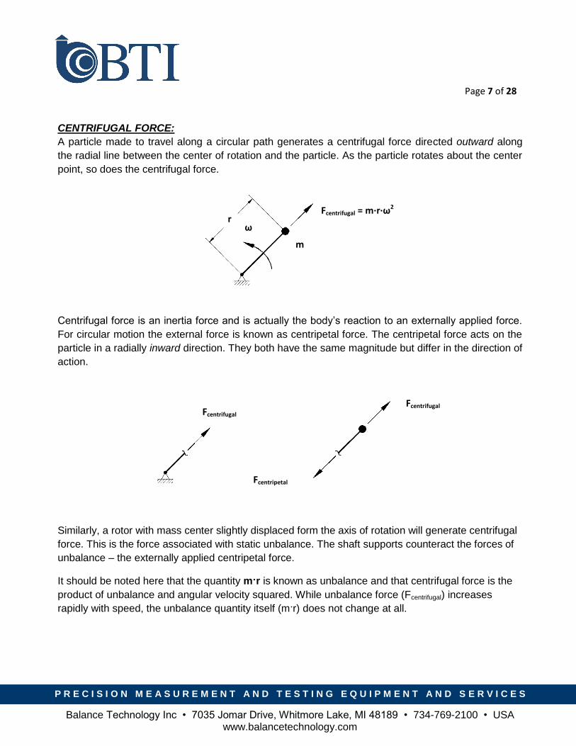
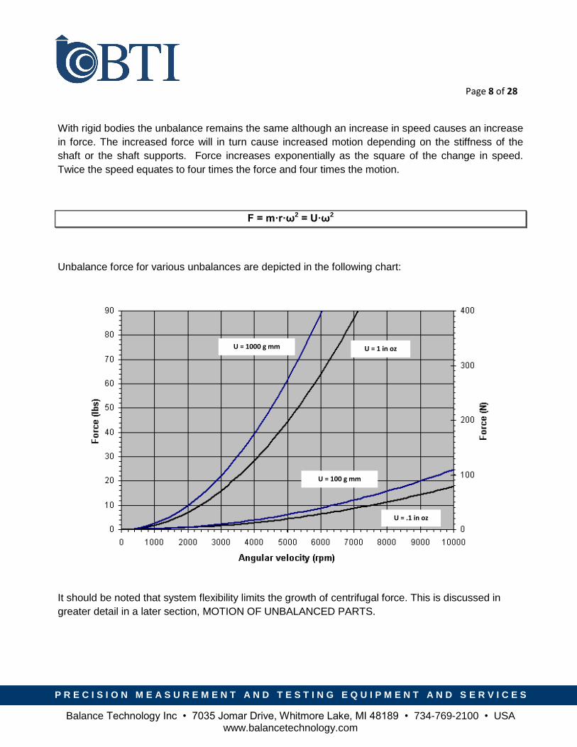
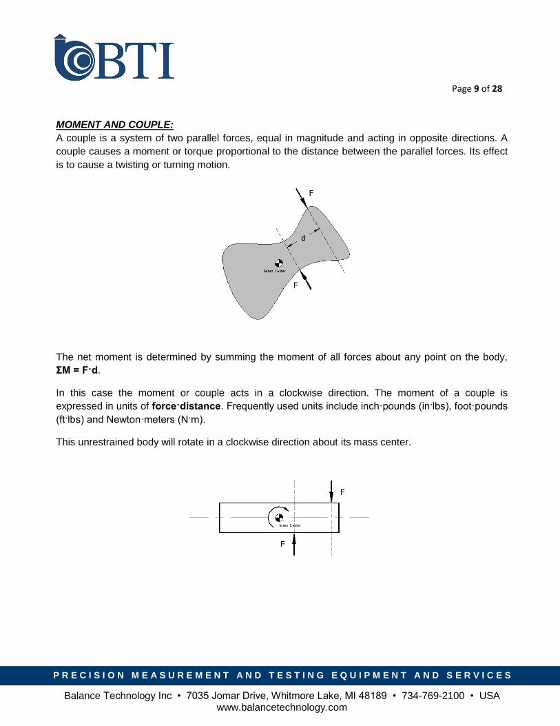
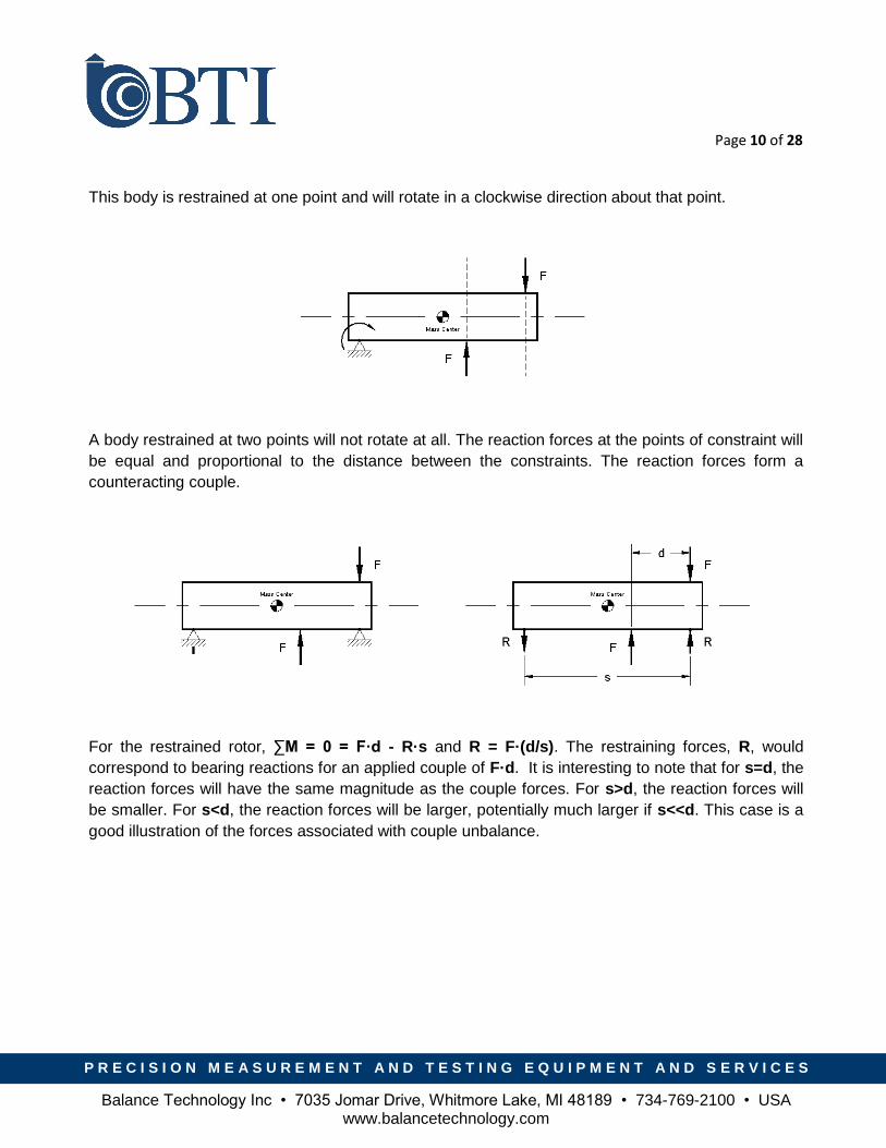
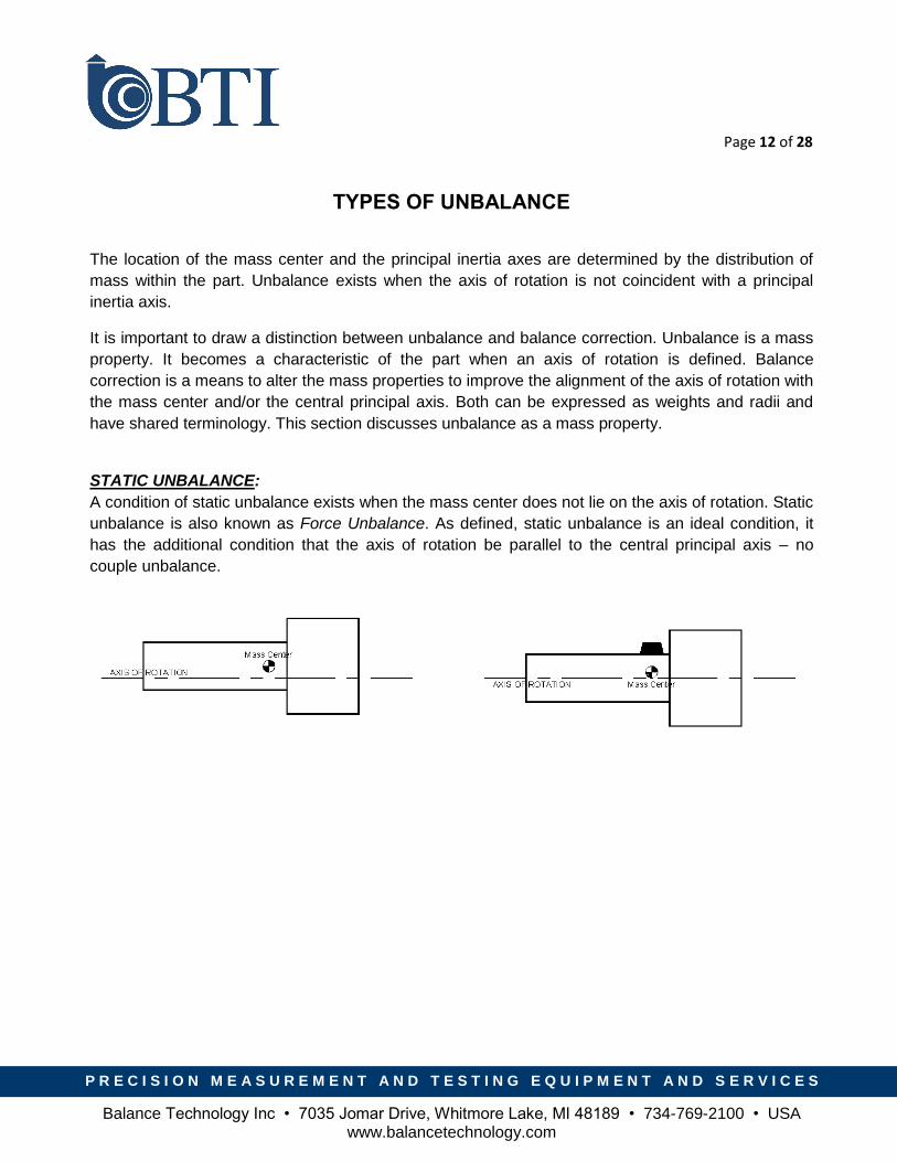
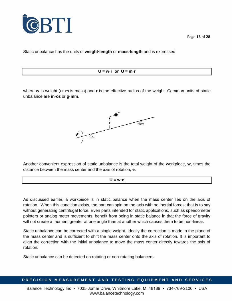
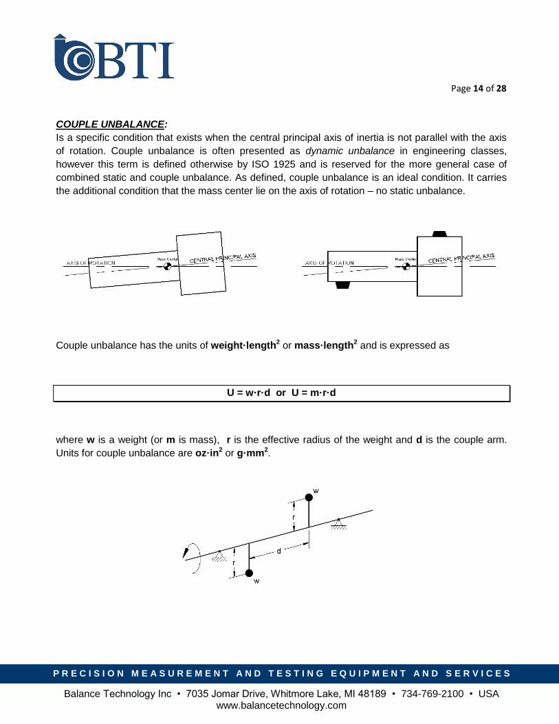
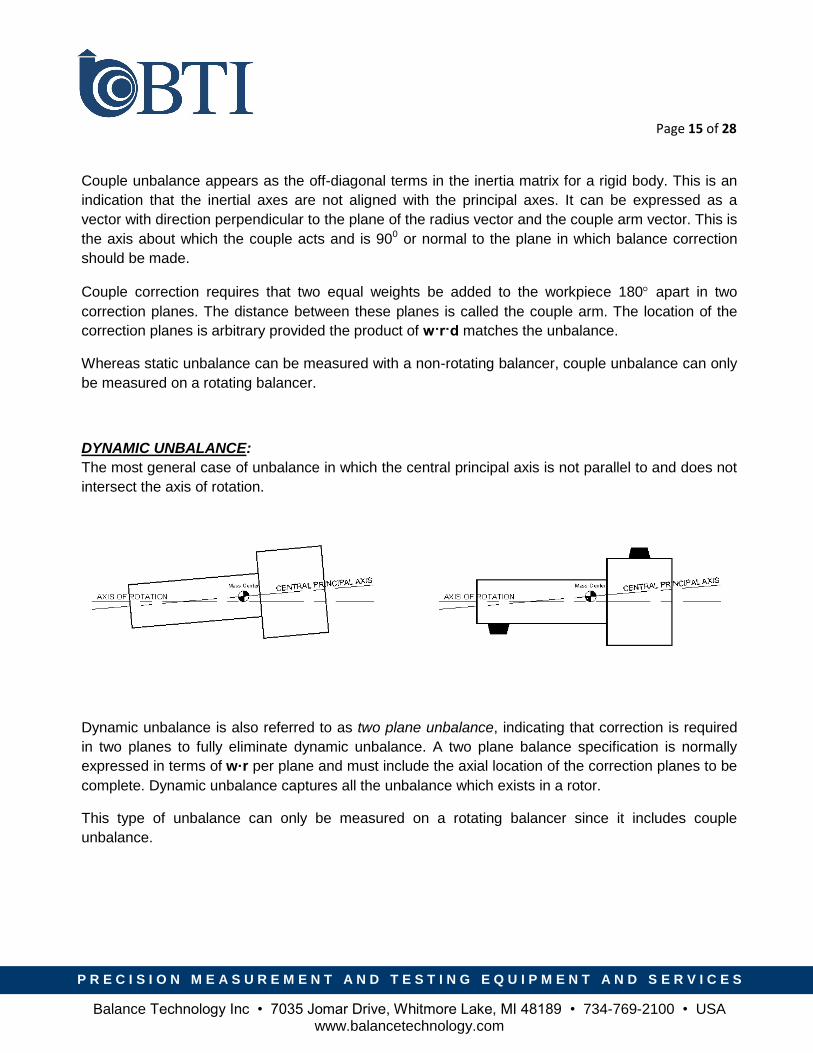
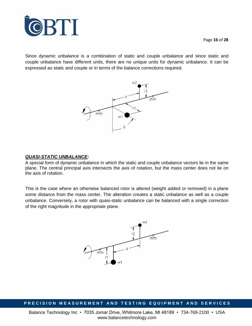
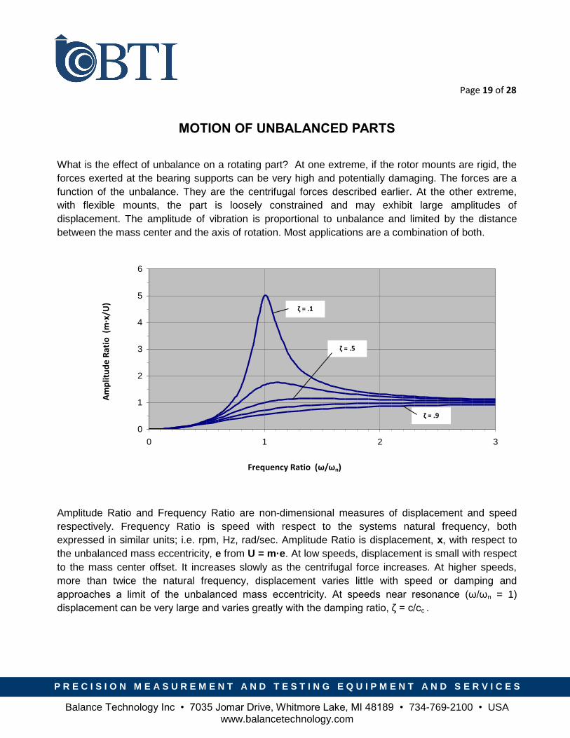
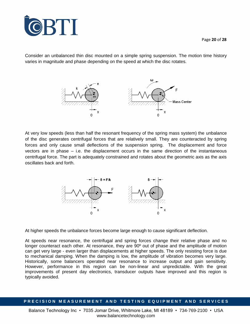
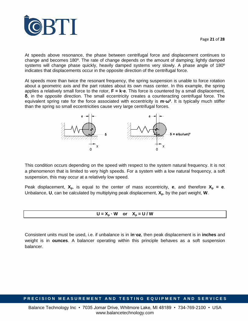
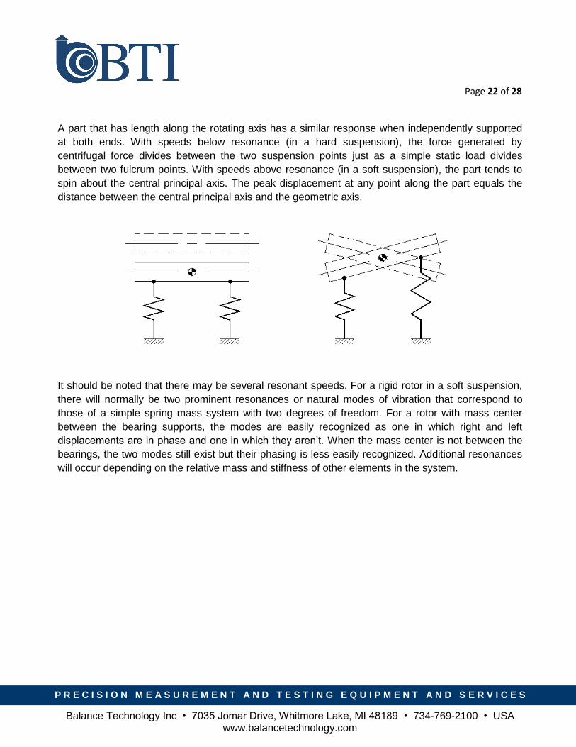
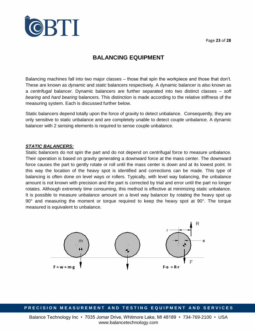
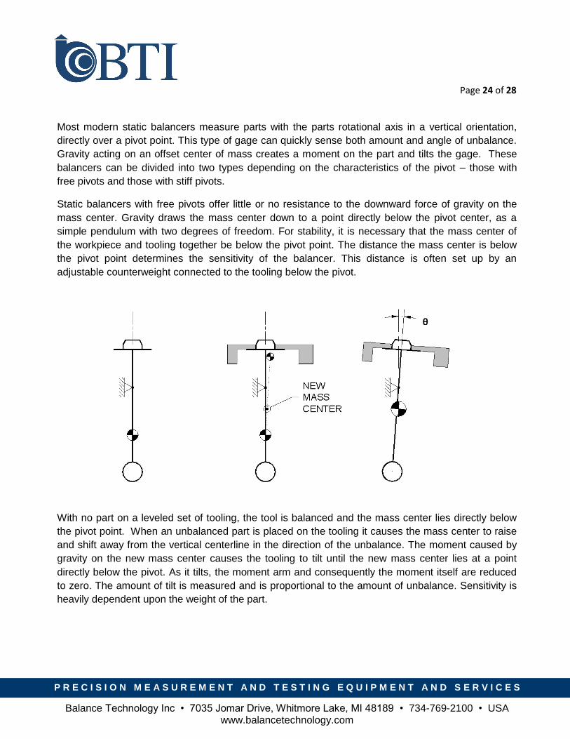
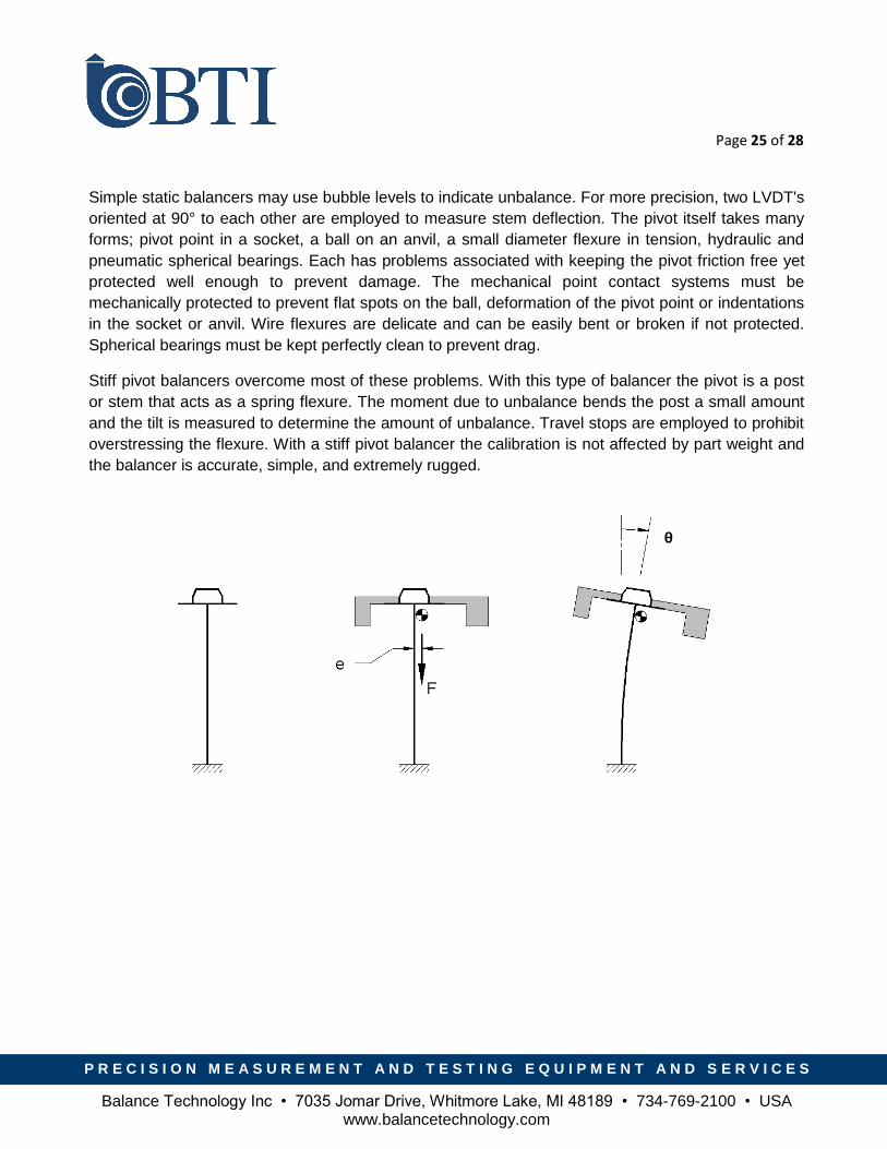
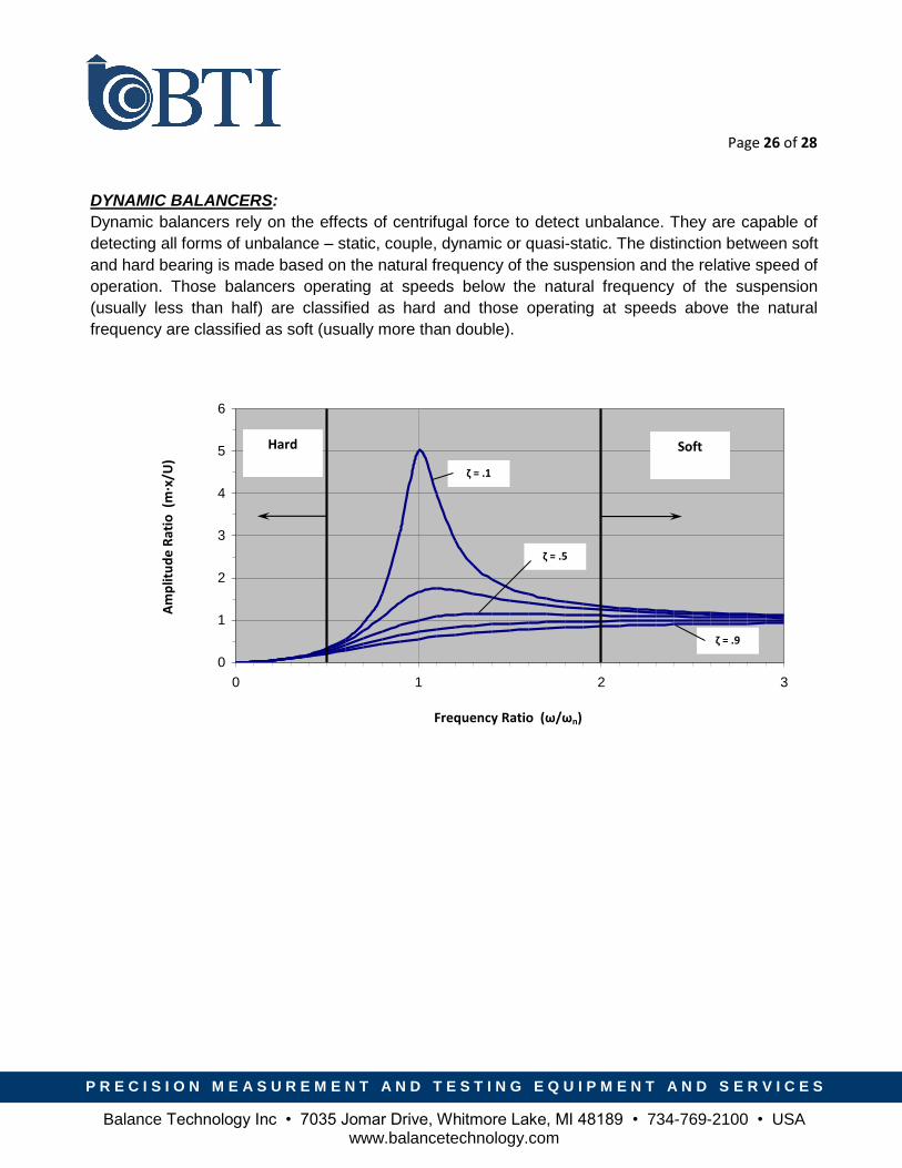
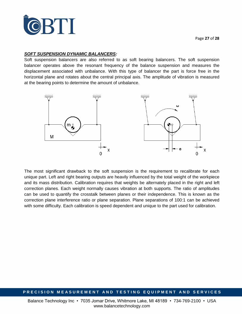
Top Related